SAFETY PRECAUTIONS CONCERNING MOUNTING, DEMOUNTING AND OPERATION
WARNING
Tire and rim servicing can be dangerous, and should be performed only by trained personnel using proper tools and procedures. Failure to comply with these procedures may result in faulty positioning of the tire and/or rim, and cause the assembly to burst with explosive force, suffi cient to cause serious physical injury or death.
DEMOUNTING
1. BEFORE DEMOUNTING
• Always exhaust all air from a single tire and from both tires of a dual assembly prior to removing any wheel components such as nuts and rim clamps.
• A broken rim part under pressure can blow apart and cause serious injury or death.
• Make sure to remove valve core to exhaust all air from the tire. Remove both cores from a dual assembly. (When you remove the wheel lugs, if the tire is still under pressure, the assembly may fly apart.)
• Check the valve stem by running a piece of wire through the stem to make sure it is not plugged. (Foreign material may clog the valve stem during deflation or ice may form as the air leaves the tire, clogging the valve stem.)
2. DURING DEMOUNTING
• Demounting tools apply pressure to rim flanges to unseat tire beads, and keep your fingers clear. Always stand to one side and hold the tool with one hand when you apply hydraulic pressure. (If the tool slips off, it can fly with enough force to cause serious injury or death.)
• Do not use tools in the vicinity of the flange butt weld.
3. AFTER DEMOUNTING
• Clean rims and repaint to stop detrimental effects of corrosion and facilitate checking and tire mounting. Be very careful to clean all dirt and rust from the lock ring and gutter. This is important to secure the lock ring in its proper position. A filter on the air inflation equipment to remove the moisture from the air line helps prevent corrosion. The filter should be checked periodically to see that it is working properly. (Parts must be clean for a proper fit - particularly the gutter section which holds the lock ring in its proper position.)
MOUNTING
1. BEFORE MOUNTING
• Check rim components for cracks. Replace all cracked, badly worn, damaged and severely rusted component with new parts of the same size and type. When a components is in doubt, replace it. (Parts that are cracked, damaged or excessively corroded are weakened. Bent or repaired parts may not engage properly.)
• Do not, under any circumstance, attempt to rework, weld, heat or braze any rim component that is cracked, broken or damaged. Replace with a new part that is not cracked, broken or damaged and which is of the same size and type. (Heating may weaken a part to extent that it is unable to withstand forces of inflation or operation.)
• Check type of rim and make sure all parts of such rim are being assembled properly. Follow instruction manual of rim or ask your distributor if you have any doubts.(Mismatched parts may appear to fi t, but when the tire is inflated they may fly apart with explosive force.)
• Mixing parts of one type rim with those of another is potentially dangerous. Always check rim with manufacturer for approval.
• Remove rust, dirt and other foreign matter from the rim surface, particularly on the bead seats and O-ring slot.
• Clean the inside of the tire.
• Make sure tube and flap are correct and not damaged for tube type tires.
• Always prepare a new O-ring for tubeless tires.
• Do not reinflate a tire that has been run flat or has been run
at 80% or less of its recommended operating pressure, or when there is obvious or suspected damage to the tire or wheel components. (Components may have been damaged or dislocated during the time the tire was run flat or seriously under-inflated.)
2. DURING MOUNTING AND INFLATION
• Do not try to seat rings or other components by hammering while tire is inflated or partially inflated.
• Double check to make sure all components are properly seated prior to inflation.
• Do not inflate tire before all components are properly in place. Place in safety cage or use a restraining device and inflate to approximately 0.35 kg/ cm2 (5 psi), recheck components for proper assembly. Observe that O-ring does not roll out of its groove. If assembly is not performed properly, deflate and correct. Never hammer or an inflated on partially inflated tire/rim assembly. If assembly is correct at approximately 0.35 kg/cm2 (5 psi), continue to inflate fully to seat the tire beads.
• Never sit or stand in front of a tire and rim assembly that is being inflated. Always use a clip-on chuck with a sufficient length of hose to permit the person inflating the tire to stand clear of the potential trajectory of the wheel components, and use an in-line valve with gauge or a pressure regulator preset to a desired value when inflating a tire. When a tire is in a restraining device, do not lean any part of your body or equipment on or against the restraining device. (If parts are improperly installed they may fly apart with explosive force.)
• Never attempt to weld on an inflated tire/rim assembly or on a rim assembly with a deflated tire. (Heat from welding will cause a sudden, drastic increase in pressure, resulting in an explosion with the force of a bomb. Deflated tires can catch fi re inside the air chamber.)
3. AFTER INFLATION
• Make sure no air leakage can be suspected, especially in tubeless tires.
OPERATION
• Do not use under-inflated tires.
• Do not bleed or reduce air pressure to compensate for the increase in pressure resulting from operation.
• Do not use under-size rims. Use recommended rim for the tire.
• Do not overload or over-inflate tire/rim assemblies. Check for adequate rim strength if special operating conditions are required. (Excessive overload can cause damage to the tire and rim assembly.)
• Never run a vehicle on one tire of a dual assembly. (The carrying capacity of the single tire and rim is dangerously exceeded, and operating a vehicle in this manner can result in damage to the rim and tire or cause a tire fi re.)
• Never use a tube in a tubeless tire/rim assembly where the rim is suspected of air leakage. (Loss of air pressure through fatigue cracks or other fractures in a tubeless rim warns you of a potential rim failure. This safety feature is lost when tubes are used with leaking rims. Continued use may cause the rim to burst with explosive force.)
• Always inspect rims and wheels for damage during tire checks. (Early detection of potential rim failure may prevent serous injury.)
• Never add or remove an attachment or otherwise modify a rim (Especially by heating, welding or brazing) unless the tire has been removed and approval has been received from the rim manufacturer. (Modification or heating of a rim or one of its parts may weaken it so that it cannot withstand forces created by inflation or operation.)
• Never mount bias tire and radial tire on the same axle. Follow vehicle manufacturer’s recommendation.
• Never use tire under unintended service conditions for the tire. Please consult YOKOHAMA if vehicle operation requires specialized tire fitment.

Specifications subject to change without notice.
GET YOUR JOB DONE ANYWHERE IN THE WORLD
OFF-THE-ROAD TIRES HANDBOOK
03, 2023 Made in Japan. ©2023 by THE YOKOHAMA RUBBER CO., LTD. CE297 CMS-OO 01

1
TRA Classification of OFF-THE-ROAD TIRES ........2 Tread Pattern .........................................................2 Tread Thickness 3 Construction of OFF-THE-ROAD TIRES.................3 Tire Marking(Radial) .............................................4 Size Identification and Aspect Ratio 4 Tire Specification Code .........................................5 Tires by Type of Vehicle ........................................6 Load Index 8 Speed Symbol 9 Conversion Table: Star Mark to Ply Rating..........9 Radial : Application Earthmover 10 Loader & Dozer .............................................11 Grader .............................................................12 Mobile Crane 12 Industrial ........................................................12 Radial : Technical Data TRA Code : E,L,G 14 Application : Mobile Crane ...........................18 TRA Code : IND ...............................................20 Appendix(Radial) 22 Bias : Application Earthmover .....................................................24 Loader & Dozer 25 Grader .............................................................28 Tire Roller .......................................................28 Industrial 29 Bias : Technical Data TRA Code : E,L,G .............................................30 TRA Code : C 44 TRA Code : IND 44 Appendix(Bias) ...............................................48 Inflation Pressure 50 Load .....................................................................51 Speed ...................................................................51 Proper Matching of Dual-Tires 52 Road Surface Maintenance ................................53 Tire Problems and Major Causes ........................53 Instructions for Operations 54 Tire Appearance Check-up .................................54 Measuring Tread Wear .......................................55 Ton-Kilometer-Per-Hour (Ton-Mile-Per-Hour) 56 Load-and-Carry Operation of Front-End Loaders 58 Protecting Tires on Vehicle in Highway Drive-Away.......................................59 Handling of Tires ................................................62 Safety Precautions for Demounting 62 Safety Precautions for Mounting ......................63 Safety Precautions for Operation ......................64 Tire Storage 65 How to Reduce Tire Costs ..................................65 Outline of OFF-THE-ROAD TIRES 1 YOKOHAMA OFF-THE-ROAD TIRES 2 Tire Maintenance 3 Tubes and Flaps 66 Rims......................................................................66 Valves ...................................................................68 O-rings 72 Combination Tables ............................................74 Rims, Valves & O-rings 4 Earthmover Data 76 Conversion Tables ...............................................79 Approximate Weight of Materials .....................81 Miscellaneous Data 5
Table of Contents
Outline of OFF-THE-ROAD TIRES
TRA Classification of OFF-THE-ROAD TIRES
YOKOHAMA OFF-THE-ROAD TIRES are classified as follows by the Tire and Rim Association (TRA).
Outline of OFF-THE-ROAD TIRES
Tread Thickness
According to the Tire and Rim Association (TRA), there are three general classifi cations for tread thickness for OFF-THE-ROAD TIRES : regular, deep and extra deep. Deep and extra deep are 1.5 and 2.5 times thicker than regular, respectively. The thicker treads have greater cut and wear resistance. Although thicker treads give greater wear and cut resistance, they also generate and retain more heat. Accordingly, work conditions for thick tread tires should be thoroughly evaluated to prevent heat separation and other heat related damage. Deep and extra deep tread tires have almost the same overall diameter which is larger than regular tread tires. When replacing regular tread tires with deep or extra deep tread tires, the larger overall diameters of the thicker tread tires should be taken into consideration.
Construction of OFF-THE-ROAD TIRES
Caution: Never replace a tire mounted on a vehicle with any tire designed for a different type of vehicle. For example, you should never place an earthmover tire on a loader
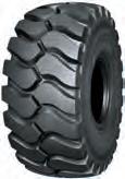
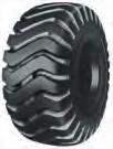
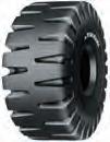
Tread Pattern
The tread pattern is designed to produce varying degrees of traction, cut resistance, flotation, wear and heat resistance. Selection of the proper OFF-THE-ROAD TIRES depends on the job and the conditions.
For example, different tread patterns are used to produce maximum traction or flotation on sand, mud and rock. There are five basic tread patterns: rock, traction, block, rib and smooth.

The steel breaker tire has steel cord breakers that give it very high cut resistance. It is specially useful where sharp rock is a problem, and is applicable to loader, dozer, dump truck and occasionally earthmover type tires. The adhesiveness between the steel cord and rubber is, however, more susceptible to heat damage than that of nylon cord and rubber. Accordingly, steel breaker tires should not be subjected to conditions where heat generation is great. Because of the difficulty involved in retreading steel breaker tires, they should not be used for jobs where more easily retreaded tires can be used.

2 3 1 1
Steel Breaker
PatternTraction PatternBlock Pattern Rib Pattern Smooth
Rock
Steel Breakers(Bias Tires)
Belt Carcass Inner Liner Bead Wire Chafer Sidewall Tread Breaker Tread Sidewall Carcass Bead Inner Steel Breaker Diagram E-3 G-2/G-3 L-2/L-3 SH-3 IND-3 E-4 L-4/L-4S SH-4 IND-4 L-5/L-5S IND-5 Vehicles TRA Code Tire Type Vehicles image Earthmover E-3Regular Tread E-4Deep Tread Subterranean Haulage SH-3Regular Tread SH-4Deep Tread Loader & Dozer L-2Traction Regular Tread L-3 Regular Tread L-4Deep Tread L-5Extra Deep Tread L-4SSmooth Deep Tread L-5SSmooth Extra Deep Tread Grader G-2Traction Regular Tread G-3 Regular Tread Compactor C-1Smooth Tread Mobile Crane -Industrial IND-3 IND-4 IND-5 Regular Tread Deep Tread Extra Deep Tread
Structural Diagram of OFF-THE-ROAD RADIAL TIRES
Structural Diagram of OFF-THE-ROAD BIAS
TIRES
Tire Marking(Radial)

Tire Specification Code Size Identification and Aspect Ratio
Widths of narrow and wide base tires of the same diameter are shown below:


4 5 1 1
Outline of OFF-THE-ROAD TIRES Outline of OFF-THE-ROAD TIRES
Brand Name Tread Pattern Name Tire Specification Code Serial Number Tire Sizer Star Mark / Load Index & Speed Symbol Tubeless or Tube Type Tire Specification Code Special Code
Narrow Base Tires Wide Base Tires 13.00 15.5 14.00 17.5 16.00 20.5 18.00 23.5 21.00 26.5 24.00 29.5 27.00 33.5 30.00 37.5 Code Type Specification CUT PROTECTED Cut Resistance Type REGULAR Regular (Standard) Type HEAT RESISTANT Heat Resistance Type Code Specification FOR SDC RIM Semi-Drop Center Rim Use Only STEEL BREAKERSteel Breaker For Bias Tires WIDE STEEL BREAKERWide Steel Breaker For Bias Tires Code Type II Specification CP-SSpecial Cut Resistance Type CP-C Cut Resistance Type RE-R Regular (Standard) Type RE-TRegular (Standard) Type With Heat Resistant HR-H Heat Resistance Type HR-VSpecial Heat Resistance Type Positioning Map of Tire Specification Code
Outline of OFF-THE-ROAD TIRES
Tires by Type of Vehicle
YOKOHAMA OFF-THE-ROAD TIRES are also classified by type of vehicle and application suitable for usage.
Dump Trucks
(TRA Codes E-3, E-4)
Since dump trucks must travel under heavy load at high speeds over relatively long distances, tires for dump trucks must have high heat and wear resistance. High resistance to cuts is sometimes also necessary.


Scrapers
(TRA Codes E-3)
Scraper tires, of which the wide base type is most common, should have the same properties as those for dump trucks. Superior flotation and traction are also occasionally required.
Outline of OFF-THE-ROAD TIRES
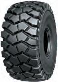
Tire Dozers
(TRA Codes L-2, L-3, L-4 and L-5)
Since a dozer is used not only for dozing and leveling, but sometimes for pushing a motor scraper, tires with better traction than loader tires are necessary. Other requirements vary widely depending on job conditions.

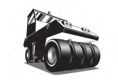
Tire Rollers
(TRA Code C-1)
Tire rollers use wide tread tires that uniformly distribute weight because of their primary use in compacting road surfaces.

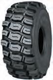
Motor Graders
(TRA Codes G-2 and G-3)
The motor grader, which is used for road leveling, clearing and snow removal, needs tires that provide high traction and directional stability. Other characteristics depend on job requirements.
Subterranean Haulage Trucks
(TRA Code SH-3 and SH-4)


Subterranean Haulage trucks run on narrow and poor road surfaces. In addition, it is difficult to change vehicle sizes larger, so they are used under high speeds and high loads conditions for efficient haulage. Therefore, the tires must have cut and heat resistance, and durability.
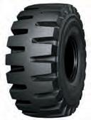
Front-End Loaders
(TRA Codes L-2, L-3, L-4, L-5, L-4S and L-5S)
Since front-end loaders operate on rough ground, cut and wear resistance are vital and the tires must provide stability for the loader body. Flotation and traction properties may also be necessary, depending on the working conditions. In certain cases, such as the wet and rough conditions of underground mines, the L-4S and L-5S with smooth treads are used because of their high wear and cut resistant properties.


Rubber Tired Gantry Crane(RTG) (TRA
Codes IND-3 and IND-4)
Rubber tired gantry cranes are special cranes mainly used to load and unload containers at seaport areas. These tires require abrasion resistance and durability.

Straddle Carriers
(TRA Code IND-3 and IND-4)
Straddle carriers are special vehicles that are mainly used at seaport areas to carry ocean-going freight containers. These tires require extra heavy-duty performance, and wear and heat resistance, because straddle carriers operate continuously and turn frequently.

Towing Tractors
(TRA Code IND-3)
Towing tractors are used to move large aircraft. Thus, these tires mainly require extra traction.
6 7 1 1
Outline of OFF-THE-ROAD TIRES
Load Index
The Load Index is a international numerical code associated with the maximum load a tire can carry at the speed indicated by its Speed Symbol under service specified conditions.
Outline of OFF-THE-ROAD TIRES
Speed Symbol
The Speed Symbol indicates the speed at which the tire can carry a load corresponding to its Load Index under service specified conditions.
Conversion Table: Star Mark to Ply Rating
*Star Mark: The load capacity of a tire is indicated by the Star Mark in case of radial tire.
8 9 1 1
YOKOHAMA OFF-THE-ROAD TIRES


YOKOHAMA OFF-THE-ROAD TIRES


ApplicationTechnical Data Radial Appendix 10 11 2 2
Tire SizeStar Mark TRA Code Pattern E-3E-3E-3E-3E-4E-4E-4E-4E-4E-4E-4E-4 RT31RT32RB31RL31RT41RL45RB41RB42RB42ARL42RL47RL47A Type T/LT/LT/LT/LT/LT/LT/LT/LT/LT/LT/LT/L 14.00R25NHS ☆☆☆ ● 16.00R25 ☆☆ ● 18.00R33 ☆☆ ●●● 24.00R35 ☆☆ ●●● 27.00R49 ☆☆ ● ● 33.00R51 ☆☆ ● ● 17.5R25 ☆☆ ●● 20.5R25 ☆☆ *● ●● 23.5R25 ☆☆ ● ● *● ● 750/65R25 ☆☆ ● 26.5R25 ☆☆ *● ● ●● 29.5R25 ☆☆ ● ●● 37.25R35 ☆☆ ●● Tire SizeStar Mark TRA Code / Pattern L-3L-3L-3L-4L-4L-5L-5L-5S L-2 RT31RB31RL31RT41RL45RL51RL52R69 MYX S01 Type T/LT/LT/LT/LT/LT/LT/LT/LT/LT/L 18.00R25 ☆☆ ● 17.5R25 ☆ ●● ● ● 20.5R25 ☆ *● ●● ● ● 23.5R25 ☆ ●● *● ● ● 750/65R25 ☆ ● 26.5R25 ☆ *● ● ●● ● 29.5R25 ☆ ● ●● ● 875/65R29 ☆ ●
L-3+,Tread Depth 125% level
: L-3+,Tread Depth 125% level
*
*
&
Traction Rock Heat Resistance NHS Not for highway service T/L Tubeless Type T/L : Tubeless Type RT31 RT31 RT32 RB31 RB31 RL31 RB41 RB42A RL31 RL45 RL45 RL51 RT41 RT41 RL42 Traction Rock Heat Resistance RB42 RL52 R69 RL47 RL47A
Radial : Application Radial : Application Earthmover Loader
Dozer


ApplicationTechnical Data Radial Appendix 12 13 2
Grader * The tread design for both 17.5R25 and 20.5R25 are slightly different. TG Tractor-Grade tire. Not for highway service. NHS Not for highway service T/T Tube Type T/L Tubeless Type Mobile Crane Tire Size Star Mark LI/SS Pattern RB01 RB03 RS01 Type T/T T/L T/T T/L T/L 14.00R24NHS ☆☆☆ ● 325/95R24161E ● 385/95R25170E ● ● ● 385/95R25170F ● ● 445/95R25177E ● 445/95R25174F ● 505/95R25183E ● 525/80R25176F ● Industrial Tire Size Star Mark LI/SS TRA Code / Pattern IND-4IND-4IND-4 RL43RR41RR42 Type T/T T/L T/L 14.00R24NHS ☆☆☆ ● 16.00R25 ☆☆☆ ● 16.00R25202A5 ● 480/95R25206A5 ● Tire SizeStar Mark TRA Code / Pattern G-2 G-2 G-2 RT21 * MYX S01 RS02 Type T/L T/L T/L 14.00R24TG ☆ ● ● 17.5R25 ☆ ● 20.5R25 ☆ ●
YOKOHAMA OFF-THE-ROAD TIRES Radial : Application
ApplicationTechnical Data Radial Appendix 14 15 2 2 YOKOHAMA OFF-THE-ROAD TIRES YOKOHAMA OFF-THE-ROAD TIRES
: Technical Data TRA Code : E,L,G TG : Tractor-Grade tire. Not for highway service. NHS : Not for highway service • Type T/T Tube Type T/L : Tubeless Type • Specification Code CP Cut Protected REG : Regular HR Heat Resistant CPUG : Cut Protected for Underground • PSI × 0.0703 = kg/cm2 POUND × 0.4536 = kg PSI × 6.895 = kPa Tire SizePattern Star Mark Type TRA Code or Application Inflated Dimensions Static Loaded Radius Static Loaded Width Groove Depth TKPHTMPHSpecTube Size Rim Size Flange Height Tire SizePattern Application Max Speed Tire Load Limits at Various Cold Inflation Pressures Overall Diameter Overall Width km/h mph T/ TT/L mminchmminchmminchmminchmm1/32 14.00R24TG RT21 ☆ - ○ G-2 134653.035614.062124.443317.024.631 ----8.00TG 14.00R24TG RT21 RS02 Grader kPa 200225250275300325350 375 psi29333640444751 54 RS02 134853.136214.361024.042016.523.630 40 kg2240243026502800300032503350 3650 ☆1 25 lbs4940536058406150660071507400 8050 ☆1 14.00R25NHSRB41 ☆☆☆ - ○ E-4140555.339315.565225.743117.038.04811982REG -10.00-1.5 14.00R25NHSRB41 Earthmover kPa 450475500525550575600625650675700725750775 800 psi65697376808387919498102105109112 115 50 kg40004125437545004625475050005150530054505600571058305940
☆3
13400☆3
○
160110REG -11.25-2.0 16.00R25RB41 Earthmover kPa 450475500525550575600625650675 700 psi65697376808387919498 102 12485CP 50 kg5150545056005800600063006500670069007100 7300 ☆2 30 lbs11400120001230012800132001390014300148001520015700 16100☆2 18.00R25R69 ☆☆ - ○ L-5S167365.950019.776029.957122.585.0107--CPUG-13.00-2.5 18.00R25R69 Loader & Dozer kPa 525550575600625650675700725750775800 825 psi76808387919498102105109112116 120 10 kg112001180012150125001285013200136001400014500150001500015500 16000 ☆2 5 lbs247002600026800276002830029100300003090032000331003310034200 35300☆2 18.00R33 RB42 ☆☆ - ○ E-4 187073.650720.085733.756922.455.370 13593CP-S -13.00-2.5 18.00R33 RB42 RB42A RL42 Earthmover kPa 450475500525550575600625650675 700 168115CP 250171HR psi65697376808387919498 102 RB42A 187573.851120.185333.656822.455.370 13593CP-S 168115CP 50 kg7750800085008750900092509750100001030010600 10900 ☆2 250171HR RL42 185573.050219.885933.856422.250.063 13593CP-S 30 lbs17100176001870019300 198002040021500220002270023400 24000☆2 168115CP 250171HR 24.00R35 RB42 ☆☆ - ○ E-4 217085.465625.897838.574529.3 63.580 253173CP-S -17.00-3.5 24.00R35 RB42 RL42 Earthmover kPa 450475500525550575600625650675 700 277190CP 304208REG psi65697376808387919498 102 422289HR RB42A 218085.866626.298038.674829.4 253173CP-S 277190CP 50 kg13200136001400014500155001600016500170001750018000 18500 ☆2 304208REG 422289HR RL42 216685.365025.697838.574929.558.774 253173CP-S 30 lbs29100300003090032000342003530036400375003860039700 40800☆2 277190CP 422289HR 27.00R49 RB42 ☆☆ - ○ E-4 2683105.673528.9122048.083032.773.793 350240CP-S -19.50-4.0 27.00R49 RB42 RL47A Earthmover kPa 450475500525550575600625650675 700 430295CP 535367REG psi65697376808387919498 102 615422HR RL47A 2669105.173528.9121347.883032.766.584 370254CP-S 50 kg19500200002060021800224002300023600250002575026500 27250 ☆2 454311CP 565387REG 30 lbs43000441004540048100494005070052000551005680058400 60000☆2 650446HR 33.00R51 RB42 ☆☆ - ○ E-4 3061120.592036.2138054.3102140.291.0115 480329CP-S -24.00-5.0 33.00R51 RB42 RL47A Earthmover kPa 450475500525550575600625650675 700 600411CP 680466REG psi65697376808387919498 102 805550HR RL47 3055120.392036.2137554.1103040.688.0111 470322CP-S 50 kg27250290003000030750325003350034500355003650037500 38750 ☆2 590404CP 670459REG 30 lbs60000640006600068000715007400076000785008050082500 85500☆2 790541HR
Radial
6050
30 lbs880091009650990010200105001100011400117001200012300125001280013100
16.00R25RB41 ☆☆ -
E-4153260.345017.770627.850019.745.157
☆ L-3147658.153020.965825.961024.033.843--
Loader & Dozer kPa 400425450475 500 RL31 ☆☆ E-3149658.953621.168627.057122.535.14413593
16100☆2
58.853421.067526.659023.230.138
CP-24.00-3.0
ApplicationTechnical Data Radial Appendix 16 17 2 2 YOKOHAMA OFF-THE-ROAD TIRES YOKOHAMA OFF-THE-ROAD TIRES Radial : Technical Data TRA Code : E,L,G *1 E-3+, L-3+, Tread Depth 125% level • Type T/T Tube Type T/L : Tubeless Type • Specification Code CP Cut Protected REG : Regular HR Heat Resistant CPUG : Cut Protected for Underground • PSI × 0.0703 = kg/cm2 POUND × 0.4536 = kg PSI × 6.895 = kPa Tire SizePattern Star Mark Type TRA Code or Application Inflated Dimensions Static Loaded Radius Static Loaded Width Groove Depth TKPHTMPHSpecTube Size Rim Size Flange Height Tire SizePattern Application Max Speed Tire Load Limits at Various Cold Inflation Pressures Overall Diameter Overall Width km/h mph T/ TT/L mminchmminchmminchmminchmm1/32 17.5R25 RB31 ☆☆ - ○ E-3134853.144217.462324.548619.131.03913190 CP -14.00-1.5 17.5R25 RB31 RL31 RL52 Earthmover kPa 275300325350375400425450475500 525 psi40444751545862656973 76 ☆ L-3134853.144217.460723.950019.731.039-- 50 kg3350355037504000412543754625475050005150 5450 ☆2 30 lbs74007850825088009100965010200105001100011400 12000☆2 RL31 ☆☆ E-3134252.844517.562224.548619.131.94012485 Loader & Dozer kPa 400425450475 500 ☆ L-3134252.844517.561724.348919.331.940 psi 58626569 73 10 kg 6000615065006700 7100 ☆1 RL52 ☆ L-5140055.146518.363825.151820.470.088 5 lbs 13200136001430014800 15700☆1 MYX S01 ☆ G-2133452.544517.561024.049519.527.234MYX SO1 Grader
kPa 125150175200225250275 300 psi18222529333640 44 40 kg1850212023602650290030753350 3650 ☆1 25 lbs4080468052005840640068007400 8050☆1
10
1 5
☆1 20.5R25 RT31 ☆☆ - ○ *1 E-3149058.753521.167626.658623.140.75113995 CP -17.00-2.0 20.5R25 RT31 RB31 RL31
RB31 ☆☆
L-2133452.544517.560023.651020.127.234 Loader & Dozer kPa 400425450475 500 psi58626569 73
kg6000615065006700 7100 ☆
lbs13200136001430014800 15700
RL52 Earthmover kPa 275300325350375400425450475500 525 psi40444751545862656973 76 ☆ *1 L-3149058.753521.165825.961024.040.751-50 kg4375475050005300560058006150650067006900 7300 ☆2
E-3147658.153020.967626.658623.133.843153105 30 lbs9650105001100011700123001280013600143001480015200
☆
1
L-5155061.055721.970427.762524.678.098 5 lbs
☆1 MYX S01 ☆ G-21494
MYX SO1 Grader kPa
300 psi18222529333640 44 40 kg2430280031503450387541254375 4625☆1 25 lbs5360615069507600855091009650 10200☆1 L-21494 58.853421.065525.861024.030.138 Loader & Dozer kPa 400425450475 500 psi58626569 73 10 kg8000825087509000 9500 ☆1 5 lbs17600182001930019800 20900☆1 23.5R25 RT31 ☆☆ - ○ E-3160063.061224.172028.367226.535.845175120 CP -19.50-2.5 23.5R25 RT31 RB31 RL31 RT41 Earthmover kPa 275300325350375400425450475500 525 ☆ L-3160063.061224.170327.769427.335.845-- psi40444751545862656973 76 RB31 ☆☆ E-3160063.061224.172028.367226.535.945168115 50 kg5600600065006700710075007750825085009000 9250 ☆2 ☆ L-3160063.061224.170327.769427.335.945-30 lbs12300132001430014800157001650017100182001870019800 20400☆2 RL31 ☆☆ *1 E-3160163.062624.672028.366526.240.751146100
RT31 RB31 RL31 RT41 RL51 Loader &
400425450475
RT41
E-4161463.560623.972828.767426.554.068
psi 58626569
10 kg 10300106001120011500 12150 ☆1 ☆
5 lbs 22700234002470025400
☆1 RL51 ☆
psi 58626569 73
L-3149658.953621.167326.559523.435.144 10 kg 8000825087509000 9500 ☆
RL52 ☆
17600182001930019800 20900
125150175200225250275
☆ *1 L-3160163.062624.670327.768226.940.751--
Dozer kPa
500
☆☆
13995
73 12384CPUG
L-4161463.560623.970827.969127.254.068-- CP
26800
L-5165865.362124.474029.169427.378.399--
750/65R25RT31 ☆☆ - ○ E-3162063.874329.373028.781732.243.755225154
750/65R25RT31 Earthmover kPa 275300325350375400425450 475 psi4044475154586265 69 50 kg690073007750825087509250975010300 10600 ☆2 30 lbs1520016100171001820019300204002150022700 23400☆2 ☆ L-3162063.874329.370727.883532.943.755-Loader & Dozer kPa 400425450 475 psi 586265 69 10 kg 132001360014500 15000 ☆1 5 lbs 291003000032000 33100☆1
505/95R25RB01183E- 〇 Mobile Crane 160563.251520.373929.156622.325.232----13.00-2.5
505/95R25RB01183E
km/h0Creep51030405060
ApplicationTechnical Data Radial Appendix 18 19 2 2 YOKOHAMA OFF-THE-ROAD TIRES YOKOHAMA OFF-THE-ROAD TIRES Radial : Technical Data TRA Code : E,L,G Application : Mobile Crane *1 E-3+, L-3+, Tread Depth 125% level • Type T/T Tube Type T/L : Tubeless Type • Specification Code CP Cut Protected REG : Regular HR Heat Resistant CPUG : Cut Protected for Underground NHS : Not for highway service • PSI × 0.0703 = kg/cm2 POUND × 0.4536 = kg PSI × 6.895 = kPa Tire SizePattern Star Mark LI/SS Type TRA Code or Application Inflated Dimensions Static Loaded Radius Static Loaded Width Groove Depth TKPHTMPHSpecTube Size Rim Size Flange Height Tire SizePattern Star Mark LI/SS kPa psi Tire Load Limits at Various Speeds Overall Diameter Overall Width T/ TT/Lmminchmminchmminchmminchmm1/32 325/95R24RB03161E ○Mobile Crane 124549.032812.958122.936014.21924--- 325/95R24 8.50V 325/95R24RB03161E km/h0Creep51030405060 70 8090100 900 mph Stationary Creep3520253035 43 505562 130 kg14010113801008087406010574054605180 4625(161E) 379532402775 lbs3080025100220001920013200126001200011400 10200(161E) 840072006100 14.00R24NHSRB01 ☆☆☆ ○Mobile Crane 135353.338415.162524.642416.722.528--- 14.00R24/25 10.00W 14.00R24NHSRB01 ☆☆☆ km/h0Creep51040 45 50 900 mph Stationary Creep3525 28 30 130 kg163001320011700101006800 6500☆3 6200 lbs3590029100258002230015000 14300☆3 13700 385/95R25 RB01 170E - ○ Mobile Crane 135353.338415.162924.842016.522.528 ----10.00-1.5 385/95R25 RB01 RB03 RS01 170E km/h0Creep51030405060 70 8090100 mph Stationary Creep3520253035 43 505562 170F kg182001480013100113007800740071006700 6000(170E) 490042003600 RB03 170E 135253.237714.863324.941416.323.830 900 lbs4010032600289002490017200163001570014800 13200(170E) 1080093007900 170F RB01 RB03 170F 130 km/h 0Creep5103040506070 80 90100 mph Stationary Creep352025303543 50 5562 RS01170E 135053.135013.862824.741716.42430 kg 15000---126001080075006900670066006300 6000(170F) 56005100 lbs 33100 27800238001650015200148001460013900 13200(170F) 1230011200 445/95R25RB01 177E - ○ Mobile Crane 148558.544517.569027.248719.223.329----11.25-2.0 445/95R25RB01 177E km/h0Creep51030405060 70 8090100 mph Stationary Creep3520253035 43 505562 kg221201796015910138009490905086108180 7300(177E) 600051004400 900 lbs48800 39600 351003040020900200001650016300 16100(177E) 13200112009700 174F 174F 130 km/h0Creep5103040506070 80 90100 mph Stationary Creep352025303543 50 5562 kg16800---141001210084007700750074007000 6700(174F) 63005700 lbs37000 31100267001850017000165001630015400 14800(174F) 1390012600
70 8090100 800 mph Stationary Creep3520253035 43 505562 116 kg265002150019100165001140010900103009800 8750(183E) 720061005300 lbs5840047400421003640025100240002270021600 19300(183E) 159001340011700 525/80R25RB03176F- ○ Mobile Crane 147458.054421.468627.058122.93139----17.00-2.0 525/80R25RB03176F km/h0Creep5103040506070 80 90100 700 mph Stationary Creep352025303543 50 5562 102 kg17800---149001280089008200800078007500 7100(176F) 67006000 lbs39400 32900283001970018100177001720016600 15700(176F) 1480013260 Tire SizePattern Star Mark Type TRA Code or Application Inflated Dimensions Static Loaded Radius Static Loaded Width Groove Depth TKPHTMPHSpecTube Size Rim Size Flange Height Tire SizePattern Application Max Speed Tire Load Limits at Various Cold Inflation Pressures Overall Diameter Overall Width km/h mph T/ TT/L mminchmminchmminchmminchmm1/32 26.5R25 RT31 ☆☆ - ○ *1E-31731 68.166826.377830.674829.445.657182125 CP -22.00-3.0 26.5R25 RT31 RB31 RT41 RL45 Earthmover kPa 275300325350375400425450475500 525 ☆ *1L-31731 68.166826.376029.976530.145.657-- psi40444751545862656973 76 RB31 ☆☆ E-31732 68.267526.678530.974429.338.849182125 50 kg7100750080008500900095009750103001060011200 115002☆2 ☆ L-31732 68.267526.676330.076029.938.849-30 lbs15700165001760018700198002090021500227002340024700 254002☆2 RT41 ☆☆ E-41732 68.267526.678130.774029.160.176 160110 14398CPUG RT31 RB31 RT41 RL45 RL52 Loader & Dozer kPa 400425450475 500 ☆ L-41732 68.267526.675729.876130.060.176-CP psi 58626569 73 RL45 ☆☆ E-41760 69.367526.679631.374429.360.176160110 10 kg 12850132001400014500 150001☆1 ☆ L-41760 69.367526.677630.676930.360.176-5 lbs 28300291003090032000 331001☆1 RL52 ☆ L-51784 70.269727.480031.573729.096121-29.5R25 RB31 ☆☆ - ○ E-31850 72.876029.983132.784233.14860270185 CP -25.00-3.5 29.5R25 RB31 RT41 RL52 Earthmover kPa 275300325350375400425450475500 525 psi40444751545862656973 76 ☆ L-31850 72.876029.980631.786634.14860-50 kg85009250975010300109001150011800125001285013600 140002☆2 RT41 ☆☆ E-41865 73.476029.984633.383332.86582 204140 182125CPUG 30 lbs18700204002150022700240002540026000276002830030000 309002☆2 ☆ L-41865 73.476029.983332.885533.76582--CP Loader & Dozer kPa 400425450475 500 RL45 ☆☆ E-41901 74.877030.386033.985033.56582 204140 CP 204140 psi 58626569 73 ☆ L-41901 74.877030.384033.187334.46582--CP 10 kg 15500160001700017500 180001☆1 RL52 ☆ L-51923 75.778931.185533.788835.0105132--CP 5 lbs 34200353003750038600 397001☆1 875/65R29RT41 ☆ - ○ L-41880 74.086734.1803.731.696237.96076--CP -27.00-3.5 875/65R29RT41 Loader & Dozer kPa 400425450 475 psi 586265 69 10 kg 185001950020600 21200☆1 5 lbs 408004300045400 46700☆1 37.25R35 RT31 ☆☆ - ○ E-3 237593.596838.1105041.3106041.75569 364249CP-S -31.00-4.0 37.25R35 RT31 RT32 Earthmover kPa 275300325350375400425450475500 525 565387REG psi40444751545862656973 76 RT32 273093.396838.1105041.3106041.75569 422289CP-S 50 kg14500155001650017500185001950020600212002240023000 23600 653448REG 30 lbs32000342003640038600408004300045400467004940050700 52000
Radial : Technical Data
RR42202A5 149058.742816.966026.049819.65063
km/h0Creep510152025
1000 mph Stationary Creep35101215
145 kg22300198001800016700161001570015500
lbs49200437003970036800355003460034200
km/h0Creep510202535
1000 mph Stationary Creep35121522
145 kg16500165001650016500150001500013875
lbs36400364003640036400331003310030600
km/h0Creep510202535
1000 mph Stationary Creep35121522
145 kg18700187001870018700170001700015725
lbs41200412004120041200375003750034700
20 21 ApplicationTechnical Data Radial Appendix 2 2
OFF-THE-ROAD TIRES
YOKOHAMA OFF-THE-ROAD TIRES YOKOHAMA
TRA Code : IND • Type T/T Tube Type T/L : Tubeless Type NHS : Not for highway service • PSI × 0.0703 = kg/cm2 POUND × 0.4536 = kg PSI × 6.895 = kPa Tire SizePattern Star Mark LI/SS Type TRA Code or Application Inflated Dimensions Static Loaded Radius Static Loaded Width Groove Depth TKPHTMPHSpecTube Size Rim Size Flange Height Tire SizePattern Star Mark LI/SS kPa psi Tire Load Limits at Various Speeds Overall Diameter Overall Width T/ TT/Lmminchmminchmminchmminchmm1/32 14.00R24NHSRL43 ☆☆☆ ○ -IND-4 137954.3 375 (365) 14.8 (14.4) 61024.0 431 (421) 17.0 (16.6) 48.061--- 14.00R24 10.00W (9.00V) 14.00R24NHSRL43 ☆☆☆ Load Wheel
1000 mph Stationary Creep35101215 145 kg18000160001450013500130001270012500
Steer Wheel
mph Stationary Creep35101215
16.00R25 RR41 ☆☆☆ - ○ IND-4 149959.042316.765625.849719.652.466 ----11.25-2.0
km/h0Creep510152025
lbs39700353003200029800287002800027600
km/h0Creep510152025 1000
145 kg14400128001160010800104001020010000 lbs31700282002560023800229002250022000
16.00R25
RR41 ☆☆☆
RR42202A5
480/95R25RR42206A5- ○ IND-4 155561.247318.668126.854221.35063----13.00-2.5
480/95R25RR42206A5
YOKOHAMA OFF-THE-ROAD TIRES
Appendix(Radial)
Haulage Service (OFF-THE-ROAD for Dump Trucks & Scrapers)
50 KPH (30 MPH) Maximum Speed Distance: Up to 4 km (2.5 miles) one way
NOTES 1. Bold face figures denote maximum load for symbols shown.
2. For 65 km/h (40 mph) maximum speed, the loads must be reduced 12% with no change in inflation pressure.
3. When haul length exceeds 4 km one way, consult your YOKOHAMA service representative.
Slow Speed Service (OFF-THE-ROAD for Loaders & Dozers)
10 KPH (5 MPH) Maximum speed Distance: Up to 76 m (250 feet) one way
NOTES 1. Bold face figures denote maximum load for symbols shown.
2. On front tires for front end loaders, it is permissible to increase inflation pressure up to 100 kPa (15 psi) above that shown in the table with no increase in load.
3. For tire load limits at various speeds:
Max. Speed % Load Change From
MPH Table
YOKOHAMA OFF-THE-ROAD TIRES
Highway Service (OFF-THE-ROAD for Mobile / Wheeled Cranes)
Size Conversion Table
NOTES: Bold face figures denote maximum load for symbols shown.
Industrial Service (OFF-THE-ROAD for Smooth Floors & Runways Use)
NOTES 1. Industrial Vehicle
Consists of usage on vehicles such as counterbalanced lift trucks, container handlers, straddle carriers, aircraft tow tractors, log stackers and rough terrain trucks.
2. Smooth Floors and Runways
These are defined as paved or protected operating surfaces which are free of undulations, obstructions or discontinuities.
3. Creep
This is movement of equipment at very slow speed (not over 60 m (200 feet) in 30 minutes). During creep motion, loads on the tires are very high and consideration must be given to the type of surface over which the equipment is traveling.
Check maximum air pressure requirements of rims and wheels to ensure ability to accommodate correct air pressure of tire.
4. Creep
This is movement of equipment at very slow speed (not over 60 m (200 feet) in 30 minutes). During creep motion, loads on the tires are very high and consideration must be given to the type of surface over which the equipment is traveling.
Tractor & Grader Service (OFF-THE-ROAD)
40 KPH (25 MPH) Maximum speed Distance: Unlimited
NOTES 1. Bold face figures denote maximum load for symbols shown.
2 For maintenance work on established highways, inflation pressures may be increased 50% if desired with no increase in loads.
3 For slope and ditching service, inflation pressures should be increased 15 psi (100 kPa) with no increase in load rating. For extreme conditions, consult tire and rim manufacturers for additional recommended operating requirements.
4. For tire load limits at various speeds with no increase in inflation pressure:
ApplicationTechnical Data Radial Appendix 22 23 2 2
Stationary +60% Creep +30% 4 km/h (2 1/2 mph) +15% 10 km/h (5 mph) No Change 15 km/h (10 mph) -13% 25 km/h (15 mph) -20% Max. Speed % Change To Loads In Table 40 km/h (25 mph) No Change 50 km/h (30 mph) -9% 60 km/h (35 mph) -18% 65 km/h (40 mph) -27% Metric Inch 325/95R24 12.00R24 385/95R24,25 14.00R24,25 445/95R25 16.00R25 505/95R25 18.00R25 525/80R25 20.5R25
5


ApplicationTechnical Data Bias Appendix 24 25 2 2 YOKOHAMA OFF-THE-ROAD TIRES YOKOHAMA OFF-THE-ROAD TIRES Bias : Application Bias : Application Earthmover Loader & Dozer : Both nylon breaker construction and steel breaker construction available s : Steel breaker construction only : Both nylon breaker construction and steel breaker construction available s : Steel breaker construction only Traction Rock Cut Resistance Heat Resistance Traction Rock Cut Resistance Heat Resistance NHS Not for highway service T/T Tube Type T/L Tubeless Type TG Tractor-Grade tire. Not for highway service. T/T Tube Type T/L : Tubeless Type NHS Not for highway service Tire Size TRA Code / Pattern E-3 E-3E-4E-4E-4 E-4 Y67 Y565Y523Y523UY567Y67E Ply Rating &Type T/TT/LT/LT/LT/LT/L T/L 10.00-20NHS 14◀ ,24◀ 11.00-20NHS 14 12.00-20NHS 16,18◀ ,24s,28s 14.00-20NHS 32 12.00-24NHS 16 14.00-24NHS 20,24,28 14.00-25NHS 24s 20◀ ,24 16.00-25 24◀ ,2824◀ ,28◀ ,32 24,28 18.00-25 32 32 32 18.00-33 32 32 32 21.00-35 36◀ ,40 24.00-35 36,42◀ ,48 24.00-49 42 27.00-49 48◀ 33.00-51 58 50◀ ,58 36.00-51 6650,58 40.00-57 68,76 68 20.5-27 28 23.5-25 32 26.5-25 26 29.5-25 28,34,36 29.5-29 28,34 34s 33.25-29 26,32 ◀ 29.5-35 34 33.25-35 32,38 37.25-35 30,36 ◀ 37.5-39 44,52 ◀ Tire Size TRA Code / Pattern L-2 L-2 L-3 L-3 L-3 Y103 Y548 Y67 Y526K Y575 Ply Rating &Type T/TT/LT/TT/LT/TT/LT/TT/LT/TT/L 12.5/70-16 6 6 10-16.5NHS 44,6 13.5-20 14 42×17-20 10 17.5/65-20 10 10 16.9-24 1010,121010,1210◀ 10◀ 18.4-24 1010 10 12.00-24NHS 16,20 13.00-24TG 16s 13.00-24NHS 18 14.00-24TG 1212 12,1612◀ ,16 14.00-24NHS 24 15.5-25 1212 1212 17.5-25 12,1612,1612,1612,1612◀ ,1612◀ ,16 1212,16 20.5-25 12,1612,1612,16,2012,16,2012,16,2016,2016◀ ,2012,16,2012,16,20 23.5-25 16 12,16,2416◀ ,20,2416s,2016◀ ,20◀ 16,2016,20,24 26.5-25 2416,20,24,26,28 2016,20,24,28 29.5-25 22,28,38 22◀ ,28,34s Y523 Y523U Y567 Y565 Y67 Y67E Y69 Y69U Y69K Y524Z Y524 Y525 Y103/Y580H Y67/Y582H Y545 Y526K Y575/Y583H Y67E


This section provides excellent cut resistance. ApplicationTechnical Data Bias Appendix 26 27 2 2 YOKOHAMA OFF-THE-ROAD TIRES YOKOHAMA OFF-THE-ROAD TIRES Bias : Application Bias : Application Loader & Dozer Loader & Dozer Loader & Dozer Special Construction of Y69U NHS Not for highway service T/T Tube Type T/L Tubeless Type NHS Not for highway service T/T Tube Type T/L : Tubeless Type ** Y524 with side protector : Both nylon breaker construction and steel breaker construction available s : Steel breaker construction only : Both nylon breaker construction and steel breaker construction available s : Steel breaker construction only Buttress Shoulder Profile Special Reinforcement (Wavy Side +ZEON Super Composite) ZEON Super Composite Steel Breaker Construction Tire Size TRA Code / Pattern L-2 L-2 L-3 L-3 Y580H Y581H Y582H Y583H Ply Rating &Type T/T T/L T/L T/T T/L T/L 13.00-24 10,12 10,12 12 14.00-24TG 12 ◆ 12 ◆ 16 ◆ 12 ◆ ,16 ◆ 17.5/65-20 10 10 16.9-24 10,12 10,12 10 18.4-24 10 17.5-25 12 ◆ 12 12,16 12,16 20.5-25 12,16 12,16 23.5-25 16 Tire Size TRA Code / Pattern L-4S L-5S L-5S L-5S Y69U Y69 Y69K Y69U Ply Rating &Type T/T T/T T/L T/L T/T T/L 12.00-20NHS 22s 12.00-24NHS 16s 16,20 16s 14.00-24NHS 20,24 18.00-25 2824,28,3228s,32 28s,32s 17.5-25 16,20,24,28 20s,28s 20.5-25 16,28 23.5-25 28 20 26.5-25 28,32,3632,36 28s,32s 29.5-29 34,40◀ 35/65-33 42s Tire Size TRA Code / Pattern L-4 L-4 L-5 L-5 L-5 L-5 Y67E Y545 Y524 **Y524**Y524ZY525 Ply Rating &Type T/L T/L T/L T/L T/L T/T 12.00-24NHS 20 17.5-25 12 20.5-25 12,16,20 23.5-25 16◀ ,20◀ ,2416,20,24 26.5-25 20,24,26,32 20,24,26,28,32◀ 29.5-25 22,28 22,28◀ 29.5-29 28 28,34s 35/65-33 24s,30s,36s,42s 24s,30s,36s,42s,48s 36s,42s 40/65-39 36s,56s 45/65-45 58s 46s ,58s 38s ,58s
◆ Both loader and grader use available


ApplicationTechnical Data Bias Appendix 28 29 2 2 YOKOHAMA OFF-THE-ROAD TIRES YOKOHAMA OFF-THE-ROAD TIRES Bias : Application Bias : Application Grader Tire Roller Industrial NHS : Not for highway service T/T : Tube Type T/L Tubeless Type : Both nylon breaker construction and steel breaker construction available s : Steel breaker construction only TG Tractor-Grade tire. Not for highway service. NHS Not for highway service T/T Tube Type T/L Tubeless Type Tire Size TRA Code / Pattern G-2 G-2 G-3 Y103 Y548Y581H Y67 Ply Rating &Type T/T T/L T/T T/T T/T T/L 11.00-20 12 12.00-24TG 12 13.00-24TG 10,1210,12 12 12 14.00-24TG 10,12,14,16,2010,12,1610,12,14,16,2012,14,16,2016 16 16.00-24TG 12 12,16 17.5-25 12 Tire Size TRA Code Pattern C-1 Y69 Ply Rating &Type T/T 7.50-16NHS 6 9.00-20NHS 10 11.00-20NHS 14 14/70-20NHS 12 15.0-20NHS 16 Tire Size TRA Code / Pattern IND-3IND-3IND-3IND-3IND-3IND-3IND-4IND-4IND-4IND-4 Y92Y67Y69Y69PSY505Y573Y523Y523UY69Y505E Ply Rating &Type T/TT/TT/LT/TT/TT/LT/TT/LT/LT/LT/LT/TT/LT/L 11.00-20NHS 16◀ ,18 12.00-20NHS 18,20 20 12.00-24NHS 20 18 20 20 20 13.00-24NHS 18,20 14.00-24NHS 24,2824,2828 2828 14.00-25NHS 24◀ 16.00-25 2828,32,36 28,3228,32 36 18.00-25 3636,40 36,40 36,4040 21.00-25 36,40 40 24.00-29 42 18.00-33 36,40◀ 40 40 21.00-35 40 24.00-35 42,48 42 27.00-49 42 33.00-51 58 36.00-51 58,72 40.00-57 68s,76 17.5-25 36 29.5-25 34 29.5-29 40 33.25-35 44 37.5-39 60
Bias : Technical Data
42×17-20Y10310-
4180 5 lbs50705390570060006280657068307160748077908090838086608940 9220
300
psi262932353841 44
10kg274029153080324033953545 3690
8130
ApplicationTechnical Data Bias Appendix 30 31 2 2 YOKOHAMA OFF-THE-ROAD TIRES YOKOHAMA OFF-THE-ROAD TIRES
TRA Code : E,L,G • Type T/T : Tube Type T/L : Tubeless Type SB Steel breaker construction • Specification Code CP : Cut Protected REG : Regular HR Heat Resistant CP-S : Cut Protected-S RE-R : Regular-R HR-H Heat Resistant-H CP-C : Cut Protected-C RE-T Regular-T HR-V Heat Resistant-V TG : Tractor-Grade tire. Not for highway service. NHS : Not for highway service * On front tires for front-end loaders. • PSI × 0.0703 = kg/cm2 POUND × 0.4536 = kg PSI × 6.895 = kPa Tire SizePattern Ply Rating Type TRA Code Inflated Dimensions Static Loaded Radius Static Loaded Width Groove Depth TKPHTMPHSpecTube Size Rim Size Flange Height Tire SizePattern Application Max Speed Tire Load Limits at Various Cold Inflation Pressures T/TT/L Overall Diameter Overall Width km/h mph SB– SB– mminchmminchmminchmminchmm1/32 12.5/70-16 Y103 6--- ○ L-2 86033.931612.438915.332913.0 21.727 ----10LB 12.5/70-16 Y103 Y548 Loader & Dozer PR (6) kPa 120 140 160 180 200 psi17 20 23 26 29 Y548 85533.732112.638815.333713.321.827 10kg1050 1145 1240 1330 1410 5 lbs2310 2520 2730 2930 3110 *10-16.5NHSY103 4- ○ - ○ L-277230.427510.835013.828611.3 18.824--10-16.5 8.25 *10-16.5NHSY103 Loader & Dozer PR (4) (6) kPa 210 240 280 310 psi 30 35 40 45 6--- ○ - 10kg 1250 1370 1480 1590 5 lbs 2760 3020 3260 3500 *13.5-20Y10314- ○ --L-2107542.334413.548319.0 36814.523.429---13.5-2011.00TG *13.5-20Y103 Loader & Dozer PR (14) kPa 180200220240260280300325350375400425450475 500 psi2629323538414447515458626569 73 10kg23002445258527202850298031003250339535353670380039304055
○ --L-2107842.441616.448219.0 43217.0 22.628---42×17-2014.00TG 42×17-20Y103 Loader & Dozer PR (10) kPa 180200220240260280
24.731 ----W14L 17.5/65-20 Y103 Y580H Y548 Y581H Loader & Dozer PR (10) kPa 120140160180200220 240 Y580H 109743.244217.449219.446018.124.731 psi 1720 23262932 35 Y548
10kg213023302520270028753040
Y581H
5 lbs470051405560595063406700 7040 *18.4-24 Y103 10 - ○ - ○ L-2 137254.0 47718.861224.151820.4 30.839 18.4-24 W16L *18.4-24 Y103 Y580H Y548 Loader & Dozer PR (10) kPa 120140160180200 220 Y580H--- ○ 137254.0 47718.860423.850619.9 30.839 - psi1720232629 32 10kg27653025327035053725 3940 Y548--- ○ 138954.549519.562624.752420.635.445 - 5 lbs61006670721077308210 8690 *16.9-24 Y10310- ○ - ○ L-2 129250.945017.758222.948018.928.436 16.9-24 W15L Y580H 10--○ 129250.945017.758222.948018.928.53612--Y548 10- ○ - ○ 130051.244817.659623.547618.734.143 16.9-24 12--- ○Y581H 10--- ○ 130051.244817.659623.547618.734.14312--- ○ Y6710 ○○○○ L-3 129551.0 44217.458823.147218.628.436 16.9-24 Y582H10--- ○ 129551.0 44217.459123.347018.528.436*16.9-24 Y103 Y580H Y548 Y581H Y67 Y582H Loader & Dozer PR (10) (12) kPa 120140160180200220 240 260 280 psi172023262932 35 38 41 10kg230025202725292031053280 3455 3620 3780 5 lbs507055606010644068507230 7620 7980 8330
5 lbs604064306790714074807820
17.5/65-20 Y103 10--- ○ L-2 109743.244217.448919.345918.1
110043.344217.449119.346718.424.831
3195
110043.344217.450119.745718.024.831
ApplicationTechnical Data Bias Appendix 32 33 2 2 YOKOHAMA OFF-THE-ROAD TIRES YOKOHAMA OFF-THE-ROAD TIRES
TRA Code : E,L,G • Type T/T : Tube Type T/L : Tubeless Type SB Steel breaker construction • Specification Code CP : Cut Protected REG : Regular HR Heat Resistant CP-S : Cut Protected-S RE-R : Regular-R HR-H Heat Resistant-H CP-C : Cut Protected-C RE-T Regular-T HR-V Heat Resistant-V TG : Tractor-Grade tire. Not for highway service. NHS : Not for highway service • PSI × 0.0703 = kg/cm2 POUND × 0.4536 = kg PSI × 6.895 = kPa Tire SizePattern Ply Rating Type TRA Code Inflated Dimensions Static Loaded Radius Static Loaded Width Groove Depth TKPHTMPHSpecTube Size Rim Size Flange Height Tire SizePattern Application Max Speed Tire Load Limits at Various Cold Inflation Pressures T/TT/L Overall Diameter Overall Width km/h mph SB– SB– mminchmminchmminchmminchmm1/32 10.00-20Y67 14 ○○ --E-3106041.728011.0 49819.629511.620.426---10.00-207.50V 10.00-20Y67 Earthmover PR (14)(24) kPa 260280300325350375400425450475 500850 psi38414447515458626569 73123 24 50kg1685176018301920200520852170224523202395 24703370 30 lbs3710388040304230442046004780495051105280 54507430 11.00-20 Y10312- ○ --G-2110743.0 30312.0 50819.732112.721.928 ---11.00-208.00V 11.00-20 Y103 Grader PR (10) (12) kPa 140 160 180 200 220 240 260 280 300 325 350 375 psi20 23 26 29 32 35 38 41 44 47 51 54 40kg1175 1275 1365 1450 1535 1615 1690 1765 1840 1925 2010 2095 25 lbs2590 2810 3010 3200 3380 3560 3730 3890 4060 4240 4430 4620 Y6714- ○ --E-3110043.329511.651020.131012.224.931 Y67 Earthmover PR (14) kPa 260 280 300 325 350 375 400 425 450 475 psi38 41 44 47 51 54 58 62 65 69 50kg1830 1910 1990 2085 2180 2270 2355 2440 2525 2605 30 lbs4030 4210 4390 4600 4810 5000 5190 5380 5570 5740 12.00-20NHS Y67 16- ○ E-3 113544.732512.853321.0 34013.425.532 ---12.00-208.50V 12.00-20NHS Y67 Y69U Earthmover PR (16) (18) (24) (28) kPa 425 450 475 500 525 550 575 600 625 650 675 700 725 750 775 18 ○○ psi62 65 69 73 76 80 83 87 91 94 98 102 105 109 112 24 ○ 50kg2800 2900 3000 3075 3150 3250 3350 3450 3550 3650 3750 3750 3875 4000 4000 28 ○ 114445.0 32212.751620.334713.725.532 30 lbs6150 6400 6600 6800 6950 7150 7400 7600 7850 8050 8250 8250 8550 8800 8800 Y69U22 ○ ---L5-S118046.532612.855721.934413.557.072 Loader & Dozer PR (18) (20) (22) kPa 750 775 800 825 850 875 900 925 psi 109 112 116 120 123 127 131 134 10kg 5800 5800 6000 6150 6150 6300 6500 6500 5 lbs 12800 12800 13200 13600 13600 13900 14300 14300 14.00-20NHSY6732- ○ --E-3125049.238615.258323.0 40115.827.535--- 14.00-2010.00WI 14.00-20NHSY67 Earthmover PR (32) kPa 500 525 550 575 600 625 650 675 700 725 750 psi73 76 80 83 87 91 94 98 102 105 109 50kg4250 4375 4500 4625 4750 4875 5000 5150 5150 5300 5450 30 lbs9350 9650 9900 10200 10450 10750 11000 11350 11350 11700 12000 12.00-24TGY10312- ○ --G-2122348.131212.356122.1 34213.526.834 11.00/12.00-24 8.00TG 12.00-24TGY103 Grader PR (12) kPa 125 150 175 200 225 250 275 300 psi18 22 25 29 33 36 40 44 40kg1450 1600 1750 1900 2000 2120 2240 2360 25 lbs3200 3520 3860 4180 4400 4680 4940 5200 12.00-24NHS Y67 16 - ○ E-3 123048.430512.0 575 22.6 330 13.0 26.4 33 8.50V 12.00-24NHS Y67 Earthmover PR (16) (20) kPa 275 300 325 350 375 400 425 450 475 500 525 550 20 psi40 44 47 51 54 58 62 65 69 73 76 80 16 L-3 559 22.0 340 13.4 26.4 33 50kg2500 2575 2725 2800 3000 3075 3150 3250 3350 3450 3550 3650 20 30 lbs5520 5680 6000 6150 6600 6800 6950 7150 7400 7600 7850 8050 Y52520 L-5128050.433013.0 596 23.5 360 14.2 58.2 74 Y67 Y525 Y69 Y69U Loader & Dozer PR (16) (20) Y69 16 L-5S128050.433313.1604 23.8 356 14.0 54.8 69 kPa 475 500 525 550 575 600 625 650 675 700 725 750 775 800 825 20 psi69 73 76 80 83 87 91 94 98 102 105 109 112 116 120 Y69U 16 ○ L-4S125449.432812.9590 23.2 348 13.7 43.3 55 10kg5000 5150 5300 5450 5600 5600 5800 6000 6150 6150 6300 6500 6700 6700 6900 16 L-5S127550.233213.1602 23.7 351 13.8 55.6 70 5 lbs11000 11400 11700 12000 12300 12300 12800 13200 13600 13600 13900 14300 14800 14800 15200 13.00-24TG Y103 10 - ○ - ○ G-2 128050.434513.657622.738315.127.034 13.00-24/25 8.00TG 13.00-24TG Y103 Y580H Y67 Y582H Grader PR (10) (12) kPa 125150175200 225 250275 300 12 psi18222529 33 3640 44 Y580H 10 128050.434513.659123.337114.627.034 40kg1700190020602240 2360 25002650 2725 12 25 lbs3740418045404940 5200 55205840 6000 Y67 12- ○ - ○ G-3 128050.4 33413.1 58623.135814.1 27.9 35 Y67 Loader & Dozer PR (12) (16) (18) kPa 375400425 450 475500525550575 600 625650 675 16-- ○ - 128850.7 36614.4 57822.838315.1 27.9 35 - psi545862 65 6973768083 87 9194 98 Y582H12--- ○ 128050.4 33413.1 59723.536514.4 27.9 35 10kg500052255415 5600 58005975615061806340 6500 66556810 6965 13.00-24Y6718- ○ --L-3128050.4 34813.7 57822.838315.1 27.9 35 13.00-24/25 13.00-24 5 lbs110201152011940 12350 1279013170135601362013980 14330 1467015010 15350
Bias : Technical Data
105109112116120 123
10kg 62857500 7750800082508250 8500 87508750900092509250 9500
5 lbs 1390016500 17100176001820018200 18700 193001930019800 2040020400 20900
14.00-24NHSY67
16.00-24TG Y103 Y67
Earthmover PR (20) (24) (28)
kPa 400425450 475 500525550 575 600625 650
psi586265 69 737680 83 8791 94
50kg425043754500 4625 475048755000 5150 53005450 5600
30 lbs935096509900 10200 105001070011000 11400 1170012000 12300
Grader PR (12) (16)
kPa 125150175200 225 250275
ApplicationTechnical Data Bias Appendix 34 35 2 2 YOKOHAMA OFF-THE-ROAD TIRES YOKOHAMA OFF-THE-ROAD TIRES Bias : Technical Data TRA Code : E,L,G • Type T/T : Tube Type T/L : Tubeless Type SB Steel breaker construction • Specification Code CP : Cut Protected REG : Regular HR Heat Resistant CP-S : Cut Protected-S RE-R : Regular-R HR-H Heat Resistant-H CP-C : Cut Protected-C RE-T Regular-T HR-V Heat Resistant-V NHS : Not for highway service • PSI × 0.0703 = kg/cm2 POUND × 0.4536 = kg PSI × 6.895 = kPa Tire SizePattern Application Max Speed Tire Load Limits at Various Cold Inflation Pressures km/h mph 14.00-24TG Y103 Y580H Y548 Y581H Y67 Y582H Grader PR (10)(12) (14) (16) (20) kPa 225250 275 300 325 350 375400425 450 psi 3336 40 44 47 51 545862 65 40kg 28003075 3250 3450 3550 3650 380039504090 4230 25 lbs 61506800 7150 7600 7850 8050 840087009000 9350 Y103 Y580H Y67 Y582H Y69 Loader & Dozer PR (12)(16) (20) (24) kPa 425575 600625650675 700 725750775800825 850 psi 6283 87919498 102
300 psi18222529 33 3640 44 40kg2650300032503450 3650 40004250 4500 25 lbs5840660071507600 8050 88009350 9900 14.00-25NHSY67 Earthmover PR (24) kPa 300325350375400425450475500525550 575 psi4447515458626569737680 83 50kg35503750387540004250437545004625475048755000 5150 30 lbs785082508550880093509650990010200105001070011000 11400 16.00-25 Y67 Y523 Earthmover PR (24) (28) (32) kPa 300 325 350 375 400 425 450 475 500 525 550 575 600 625 650 psi44 47 51 54 58 62 65 69 73 76 80 83 87 91 94 50kg4625 4875 5000 5300 5450 5600 5800 6000 6300 6500 6500 6700 6900 7100 7300 30 lbs10200 10700 11000 11700 12000 12300 12800 13200 13900 14300 14300 14800 15200 15700 16100 18.00-25 Y67 Y523 Earthmover PR (32) (40) kPa 350375400425450475500525550 575 600625650675 700 psi5154 58626569737680 83 87919498 102 50kg650069007100730075007750800082508500 8750 9000925095009500 9750 30 lbs143001520015700161001650017100176001820018700 19300 19800204002090020900 21500 Y69 Y69K Y69U Loader & Dozer PR (28) (32) kPa 375475500525550575600625 650 675700725 750 psi5469737680838791 94 98102105 109 10kg1000011500118001215012500128501320013600 13600 140001450014500 15000 5 lbs2200025400260002680027600283002910030000 30000 309003200032000 33100 Tire SizePattern Ply Rating Type TRA Code Inflated Dimensions Static Loaded Radius Static Loaded Width Groove Depth TKPHTMPHSpecTube Size Rim Size Flange Height T/TT/L Overall Diameter Overall Width SB– SB– mminchmminchmminchmminchmm1/32 14.00-24TG Y103 10- ○ - ○ G-2134152.837514.8 60423.840916.128.536 14.00-24/25 8.00TG (14PR Max.), 10.00VA 12- ○ - ○ 14- ○ 16- ○ - ○ 20- ○ Y580H 10○○ G-2 134152.8 37514.8 60423.840916.128.536 12 ○○ Y548 10- ○ 134052.836414.360823.940616.026.734 12- ○ 14- ○ 16- ○ 134052.738415.162624.642616.826.734 20- ○ Y581H 12○ 134052.837314.760823.940616.027.835 14 ○ 16 ○ 134052.837314.762624.639915.727.835 20 ○ Y10312- ○ - ○ L-2 133952.737514.859523.444217.428.536 10.00VA 10.00W Y580H12- ○ - ○ 134152.837514.859523.442016.528.536 Y6716- ○ - ○ G-3 135153.237314.762424.638815.327.735 8.00TG (14PR Max.), 10.00VA Y582 12--- ○ 13475336514.463224.540616.027.735 16 - ○ 134753.037514.8 63124.940215.8 27.735 ○ 62924.840415.9 Y67 12- ○○○ L-3 134352.9 37514.8 60423.841616.427.735 10.00VA (12PR), 10.00W 16- ○ - ○ Y582H 12--- ○ 134753.036514.460123.742216.627.735 16 - ○ 134753.037514.8 61224.141516.3 27.735 ○ 61124.041716.4 14.00-24NHS Y67 20 - ○ E-3134553.0 38015.0 62424.640816.127.735 9565CP 10.00W 24 28 24 L-3134452.9 38315.1 60423.841616.4 27.735 Y69 20 - ○ --L-5S136553.7 38015.0 65425.739315.5 63.179 24 16.00-24TG Y10312- ○ --G-2146557.7 44517.564625.449419.434.243 ---16.00-24/2510.00VA Y67 12- ○ G-3147558.1 445 17.568627.0 46718.434.343 16- ○ - ○ 14.00-25NHSY6724 ○ E-3134553.0 38015.0 624 24.6 408 16.1 27.7 35 6746CP 14.00-24/2510.00-1.5 ○ ○ 10975REG 16.00-25 Y67 24 ○○○○ E-3147558.144517.568627.0 46718.434.343 12485CP16.00-24/25 11.25-2.0 28 - ○ 32 - ○ 13995REGY523 24 ○ E-4154060.644517.472428.546718.459.37510270CP 28 18.00-25 Y6732 - ○ - ○ E-3159963.0 52020.5 73428.9 54021.3 38.5 49 160110CP18.00-25 13.00-2.5 Y523 32 ○ E-4165265.0 51720.4 77230.4 54121.3 61.3 77 13995CP40 Y69 24 ○ L-5S 165165.0 53321.0 75129.6 57122.5 83.4 104 28 - ○ - ○ 18.00-25 32 ○Y69K 28 ○○ 170066.9 52020.5 78530.9 55521.9 84.1 106 32 ○ Y69U 28 ○167065.7 536 21.1 78030.7 57122.5 84.1 106 32 ○ -
24.00-49Y523
33.00-51 Y523 Y567
Earthmover PR (42)
kPa 400425450475500525550 575
psi58626569737680 83
50kg 170001800018500190001950020000
psi404447515458626569 73 7680 83
50kg165001700018000190001950020600212002180022400 23000 2360024300 25000
30 lbs364003750039700419004300045400467004810049400 50700 5200053600 55100
Earthmover PR (50) (58)
kPa 275300325350375400425450475 500 525550 575
psi404447515458626569 73 7680 83
ApplicationTechnical Data Bias Appendix 36 37 2 2 YOKOHAMA OFF-THE-ROAD TIRES YOKOHAMA OFF-THE-ROAD TIRES
TRA Code : E,L,G • Type T/T : Tube Type T/L : Tubeless Type SB Steel breaker construction • Specification Code CP : Cut Protected REG : Regular HR Heat Resistant CP-S : Cut Protected-S RE-R : Regular-R HR-H Heat Resistant-H CP-C : Cut Protected-C RE-T Regular-T HR-V Heat Resistant-V • PSI × 0.0703 = kg/cm2 POUND × 0.4536 = kg PSI × 6.895 = kPa Tire SizePattern Application Max Speed Tire Load Limits at Various Cold Inflation Pressures km/h mph 18.00-33 Y67 Y523 Y523U Earthmover PR (32) kPa 450475500525550 575 psi6569737680 83 50kg875090009250975010000 10300 30 lbs1930019800204002150022000 22700 21.00-35Y523 Earthmover PR (36) (40) kPa 375 400 425 450 475 500 525 550 575 600 625 psi54 58 62 65 69 73 76 80 83 87 91 50kg10300 10900 11200 11500 11800 12150 12500 12850 13200 13600 14000 30 lbs22700 24000 24700 25400 26000 26800 27600 28300 29100 30000 30900
Earthmover PR (36)
425 450 475 500 525 550 575 600 625 650 psi58
80
94
15500
Bias : Technical Data
24.00-35Y523
(42) (48) kPa 400
62 65 69 73 76
83 87 91
50kg14000 14500 15000 15500
16000 16500 17000 17500 18000 18500 30 lbs30900 32000 33100 34200 34200 35300 36400 37500 38600 39700 40800
20600
45400
PR
575
30 lbs 375003970040800419004300044100
27.00-49Y523 Earthmover
(42) (48) kPa 275300325350375400425450475 500 525550
Y523 Earthmover PR
kPa 350375400425 450 475500 525 550575 600 psi51545862 65 6973 76 8083 87 50kg32500345003550036500 37500 3875040000 41250 4250043750 45000 30 lbs71500760007850080500 82500 8550088000 91000 9350096500 99000 40.00-57 Y523 Y567 Earthmover PR (68) (76) kPa 350375400425450 475500525 550 575600 625 psi5154586265697376 80 8387 91 50kg4125043750450004625048750500005150053000 54500 5600058000 58000 30 lbs910009650099000102000107500110000113500117000 120000 123500128000 128000 Tire SizePattern Ply Rating Type TRA Code Inflated Dimensions Static Loaded Radius Static Loaded Width Groove Depth TKPHTMPHSpecTube Size Rim Size Flange Height T/TT/L Overall Diameter Overall Width SB– SB– mminchmminchmminchmminchmm1/32 18.00-33 Y6732 ○ E-3180070.952020.584033.155421.841.152190130CP-C -13.00-2.5 Y52332 ○ E-4185072.851820.486934.254221.356.271153105CP-C Y523U32 ○ E-4187873.952020.587434.454521.567.0 84146100CP-C 21.00-35Y523 36 ○○ E-4204580.559023.295137.462324.563.280 190130CP-C -15.00-3.0 219150RE-R 40 ○ 190130CP-C 219150RE-R 24.00-35Y523 36 ○ E-4217585.668727.0 99039.0 71028.0 64.6 81 226155CP-C -17.00-3.5 ○ 263180RE-R 42 ○ 175120CP-S ○○ 226155CP-C ○ 263180RE-R ○ 321220HR-H 48 ○ 226155CP-C 24.00-49Y52342 ○ E-4252999.665525.8 118446.669727.4 64.6 81277190CP-C - 17.00-3.5 27.00-49Y52348 ○○ E-42679105.574829.4 124549.079131.1 71.3 90 263180CP-S - 19.50-4.0 ○○ 336230CP-C ○○ 387265RE-R ○○ 452310HR-H ○○ 496340HR-V 33.00-51 Y52358 ○ E-43039119.692736.5 140455.398538.8 82.7 104 430295CP-C - 24.00-5.0 Y567 50 ○○ 516354CP-C ○○ 613420RE-R 58 ○○ 516354CP-C ○ 664455RE-T 36.00-51 Y56566 ○ E-33200126.0 104541.1146057.5110043.351.865730500RE-T - 26.00-5.0 Y523 50 E-43198125.9 104040.9147658.1109042.992.2116481330CP-C 58 40.00-57 Y523 68 ○ E-4 3551139.8112744.4162463.9120047.292.8117 657450RE-T - 29.00-6.0 76 657450RE-T 788540HR-V Y56768 3544139.5112744.4162163.8120047.292.8117 613420CP-C 717491RE-R 945648HR-V
50kg236002430025750272502800029000300003150032500 33500 3450035500 35500 30 lbs520005360056800600006150064000660006950071500 74000 7600078500 78500 36.00-51 Y565
(50) (58) (66)
ApplicationTechnical Data Bias Appendix 38 39 2 2 YOKOHAMA OFF-THE-ROAD TIRES YOKOHAMA OFF-THE-ROAD TIRES
TRA Code : E,L,G • Type T/T : Tube Type T/L : Tubeless Type SB Steel breaker construction • Specification Code CP : Cut Protected REG : Regular HR Heat Resistant CP-S : Cut Protected-S RE-R : Regular-R HR-H Heat Resistant-H CP-C : Cut Protected-C RE-T Regular-T HR-V Heat Resistant-V • PSI × 0.0703 = kg/cm2 POUND × 0.4536 = kg PSI × 6.895 = kPa * For slope and ditching service, inflation pressure should be increased 15 psi with no increase load rating. Tire SizePattern Application Max Speed Tire Load Limits at Various Cold Inflation Pressures km/h mph *15.5-25 Y103 Y67 Loader & Dozer PR (12) kPa 225 250 275 300 325 350 375 400 psi33 36 40 44 47 51 54 58 10kg4000 4250 4500 4750 4875 5150 5300 5600 5 lbs8800 9350 9900 10500 10700 11400 11700 12300 *17.5-25 Y103 Y580H Grader PR (12) kPa 125 150 175 200 psi18 22 25 29 40kg2120 2360 2575 2900 25 lbs4680 5200 5680 6400 Y103 Y580H Y548 Y581H Y67 Y582H Y575 Y583H Y67E Y69 Y69U Loader & Dozer PR (12) (16) (20)(24)(28) kPa 350 375 400 425 450 475 500 525 550 575 700 825 psi 51 54 58 62 65 69 73 76 80 83 102 120 10kg 6150 6300 6700 6900 7100 7300 7500 7750 8000 8250 9250 10000 5 lbs 13600 13900 14800 15200 15700 16100 16500 17100 17600 18200 20400 22000 *20.5-25 Y67 Earthmover PR (28) kPa 175 200 225 250 275 300 325 350 375 400 425 450 475 psi25 29 33 36 40 44 47 51 54 58 62 65 69 50kg4125 4500 4875 5150 5450 5800 6000 6300 6500 6700 7100 7300 7500 30 lbs9100 9900 10750 11400 12000 12800 13200 13900 14300 14800 15700 16100 16500 Y103 Y548 Y67 Y582H Y526K Y575 Y583H Y524 Y69 Loader & Dozer PR (12) (16) (20) (28) kPa 250 275 300 325 350 375 400 425 450 525 625 psi 36 40 44 47 51 54 58 62 65 76 91 10kg 6700 7100 7500 7750 8250 8500 8750 9250 9500 10300 11500 5 lbs 14800 15700 16500 17100 18200 18700 19300 20400 20900 22700 25400 Tire SizePattern Ply Rating Type TRA Code Inflated Dimensions Static Loaded Radius Static Loaded Width Groove Depth TKPHTMPHSpecTube Size Rim Size Flange Height T/TT/L Overall Diameter Overall Width SB– SB– mminchmminchmminchmminchmm1/32 *15.5-25 Y103 12 - ○ - ○ L-2130051.240515.957522.643317.025.532 ---15.5-2512.00-1.3 Y67 - ○ - ○ L-3130051.240515.958923.243317.028.035 *17.5-25 Y103 12 ○ G-2 136453.743517.1 62024.446018.127.03414.00-1.5 12 - ○ - ○ L-2 59923.647718.827.034 17.5-25 16 - ○ - ○ Y580H12 ○ G-2 134853.134917.7 61624.347718.82734 L-2 59523.448719.22734 Y548 12 - ○ - ○ L-2136553.745417.961024.048619.133.242 16 Y581H12 ○ L-2136953.944617.661024.048219.033.242Y67 12 ○○○○ L-3135653.444317.460023.648319.030.338 17.5-25 16 - ○ - ○ Y582H 12 ○ L-3135653.444317.460924.048118.930.33816 ○ Y575 12 - ○○○ L-3134052.843517.159523.447318.630.238 17.5-25 16 ○Y583H 12 ○ L-3134052.843517.159623.548118.930.238 16 ○ Y67E12 ○ L-4139054.744317.463725.147418.745.057 Y69 16 ○ L-5S139054.743016.964925.645417.969.087 20 - ○ - ○ 17.5-25 24 ○28 ○ Y69U 20 ○L-5S140055.145217.865825.947318.669.087 28 ○*20.5-25 Y103 12 ○ L-2148058.354021.364725.558323.031.54017.00-2.0 16 Y548 12○ - ○ L-2150959.455121.767026.459023.233.843 20.5-25 16 20 -Y67 28 ○ E-3149058.752220.669027.254021.333.44210975HR12 - ○ - ○ L-3149859.052820.865125.657822.833.442 20.5-25 16 - ○ - ○ 20 - ○ - ○ Y582H 12 ○ L-3149859.051620.366626.256222.133.442 16 ○ Y526K 16 - ○○○ L-3148658.554221.367726.757722.734.944 20 - ○ - ○ Y575 12 - ○○○ L-3149558.953220.966326.157422.632.741 16 - ○○○ 20 - ○ - ○ Y583H 12 ○ L-3149558.953220.966526.257822.832.74116 ○ Y524 12 ○ L-5155861.353921.272128.457522.680.3101 16 20 Y69 16 ○ L-5S154560.854021.371428.156422.281.0102 28
Bias : Technical Data
ApplicationTechnical Data Bias Appendix 40 41 2 2 YOKOHAMA OFF-THE-ROAD TIRES YOKOHAMA OFF-THE-ROAD TIRES
Technical Data TRA Code : E,L,G • Type T/T : Tube Type T/L : Tubeless Type SB Steel breaker construction • Specification Code CP : Cut Protected REG : Regular HR Heat Resistant CP-S : Cut Protected-S RE-R : Regular-R HR-H Heat Resistant-H CP-C : Cut Protected-C RE-T Regular-T HR-V Heat Resistant-V • PSI × 0.0703 = kg/cm2 POUND × 0.4536 = kg PSI × 6.895 = kPa * For slope and ditching service, inflation pressure should be increased 15 psi with no increase load rating. * Not fixed yet and YOKOHAMA will inform when available Tire SizePattern Application Max Speed Tire Load Limits at Various Cold Inflation Pressures km/h mph *23.5-25 Y67 Earthmover PR (32) kPa 175 200 225250275300325350375400425450 475 psi25 29 33 36 4044475154586265 69 50kg53005800 6150 6500 69007300775080008250875090009250 9500 30 lbs1170012800 13550 143001520016100171001760018200198001980020400 20900 Y103 Y67 Y582H Y526K Y575 Y545 Y524 Y69 Loader & Dozer PR (12) (16) (20) (24)(28) kPa 225 250 275 300 325350 375 425 475 550 psi 33 36 40 44 4751 54 62 69 80 10kg 8000 8500 9000 9500 1000010600 10900 11800 1250013600 5 lbs 17600 18700 19800 20900 2200023400 24000 26000 2760030000 26.5-25 Y67 Earthmover PR (26) kPa 175 200 225 250 275 300 325 psi25 29 33 36 40 44 47 50kg6700 7300 7750 8250 8750 9250 9500 30 lbs14750 16100 17100 18200 19300 20400 20900 Y67 Y575 Y545 Y524 Y69 Y69K Y69U Loader & Dozer PR (16) (20)(24)(26)(28)(32)(36) kPa 275 300 350 400 450 475 550 625 psi 40 44 51 58 65 69 80 91 10kg 11500 12150 13200 14000 15000 15500 17000 18500 5 lbs 25350 26800 29100 30900 33100 34200 37500 40800 29.5-25 Y67 Earthmover PR (28) (34)(36) kPa 175 200 225 250 275 300 325 350 375 400 425 psi25 29 33 36 40 44 47 51 54 58 62 50kg8000 8750 9250 10000 10600 10900 11500 12150 12500 13200 13600 30 lbs17600 19300 20400 22000 23400 24000 25400 26800 27600 29100 30000 Y67 Y575 Y545 Y524 Loader & Dozer PR (22) (28) (34)(38) kPa 250 275 300 325 350 375 400 425 450 475 500 525 600 psi36 40 44 47 51 54 58 62 65 69 73 76 87 10kg12850 13600 14500 15000 16000 16500 17000 17500 18500 19000 19500 20000 21800 5 lbs28300 30000 32000 33100 35300 36400 37500 38600 40800 41900 43000 44100 48100 Tire SizePattern Ply Rating Type TRA Code Inflated Dimensions Static Loaded Radius Static Loaded Width Groove Depth TKPHTMPHSpecTube Size Rim Size Flange Height T/TT/L Overall Diameter Overall Width SB– SB– mminchmminchmminchmminchmm1/32 *23.5-25 Y10316 ○ L-2161463.559723.568627.068026.836.045---19.50-2.5 Y67 32 ○ E-3160163.058022.874529.361624.342.453146100HR 12 - ○ L-3161063.460523.870927.963625.042.453 23.5-25 16 - ○○○ 20 ○ 24 - ○ - ○ Y582H16 ○ L-3160563.259623.565625.865725.842.453 Y526K 16 ○ - ○○ L-3160163.062624.671128.066226.140.551 20 - ○○○ Y575 16 ○○○○ L-3160563.261524.270827.964525.442.253 20 - ○○○ 24 ○Y545 16 ○○ L-4167966.162924.876029.966026.056.071 20 ○○ 24 ○ Y524 16 ○ L-5168065.662024.476430.166226.188.0111 20 24 Y69 20 ○ L-5S 1645.0 64.8 600.0 23.674929.563525.093.2117 28 - ○ 23.5-25 26.5-25 Y67 26 ○ E-3 1730 68.1 700 27.6778 30.6732 28.844.9 57 153105REG22.00-3.0 16 ○ L-31745 68.7 694 27.3765 30.1738 29.144.9 57 20 ○ 26.5-25 24 - ○ - ○ 26 ○ - 28 ○ Y575 16 ○ L-31740 68.5 690 27.2770 30.3733 28.942.8 54 20 - ○○○ 26.5-25 24 ○ ○ 28 ○Y545 20 ○ L-41786 70.3 704 27.7800 31.5764 30.168.4 86 24 26 32 Y524 20 ○ L-51808 71.2 696 27.4820 32.3722 28.497.1 122 24 - ○ 26 ○ 28 ○ 32 ○○ Y69 28 ○ L-5S1798 70.8 690 27.2798 31.4731 28.886.2 109 32 36 Y69K 32 ○ L-5S1790 70.5 695 27.4825 32.5723 28.590.6 114 36 Y69U 28 ○ - L-5S1803 71.0 717 28.2837 33.0 739 29.1 90.8 114 32 29.5-25 Y67 28 ○ E-3 187673.977630.682232.482632.549.662 160110REG -25.00-3.5 175120HR 34 175120HR 36 188274.177330.484733.379831.449.662--HR 22 L-3 187673.977630.680331.683532.949.662 28 38 186573.477330.483933.078931.149.662 Y575 22 ○○ L-3185573.076530.181332.083032.749.162 28 ○○ 34 ○○ Y545 22 ○ L-4190074.878530.984733.384233.173.192 28 34 Y524 22 ○ L-5190875.1 77430.586834.2 82532.5110.9 140 28 ○○
Bias :
ApplicationTechnical Data Bias Appendix 42 43 2 2 YOKOHAMA OFF-THE-ROAD TIRES YOKOHAMA OFF-THE-ROAD TIRES
TRA Code : E,L,G • Type T/T : Tube Type T/L : Tubeless Type SB Steel breaker construction • Specification Code CP : Cut Protected REG : Regular HR Heat Resistant CP-S : Cut Protected-S RE-R : Regular-R HR-H Heat Resistant-H CP-C : Cut Protected-C RE-T Regular-T HR-V Heat Resistant-V • PSI × 0.0703 = kg/cm2 POUND × 0.4536 = kg PSI × 6.895 = kPa * Not fixed yet and YOKOHAMA will inform when available Tire SizePattern Application Max Speed Tire Load Limits at Various Cold Inflation Pressures km/h mph 26.5-29Y67 Earthmover PR (26) kPa 175 200 225 250 275 300 325 psi25 29 33 36 40 44 47 50kg7100 7750 8250 8750 9250 9750 10300 30 lbs15700 17100 18200 19300 20400 21500 22700 29.5-29 Y67 Y67E Earthmover PR (28) (34) kPa 175200225250275300 325 350375 400 psi252933364044 47 5154 58 50kg8500925010000106001120011800 12150 1285013200 14000 30 lbs187002040022000234002470026000 26800 2830029100 30900 Y67E Y524 Y69K Loader & Dozer PR (28) (34)(40) kPa 300325350375400 425 450475500 525625 psi4447515458 62 656973 7691 10kg1550016000170001750018000 19000 195002000020600 2120023600 5 lbs3420035300375003860039700 41900 430004410045400 4670052000 33.25-29Y67 Earthmover PR (26) (32) kPa 175 200 225 250 275 300 325 psi25 29 33 36 40 44 47 50kg10300 11200 12150 12850 13600 14000 15000 30 lbs22700 24700 26800 28300 30000 30900 33100 29.5-35Y67 Earthmover PR (34) kPa 175 200 225 250 275 300 325 350 375 400 psi25 29 33 36 40 44 47 51 54
12150 12850 13600
24050 25400 26800 28300 30000 30900
Bias : Technical Data
58 50kg9250 10000 10900 11500
14000 14500 15000 30 lbs20400 22050
32000 33100
PR (32) (38) kPa 175 200 225 250 275 300 325 350 375 400 psi25 29 33 36 40 44 47 51 54 58 50kg11200 12150 12850 14000 14500 15500 16000 17000 17500 18000 30 lbs24700 26800 28300 30900 32000 34200 35300 37500 38600 39700 37.25-35Y67 Earthmover PR (30) (36) kPa 175 200 225 250 275 300 325 psi25 29 33 36 40 44 47 50kg13600 14500 15500 16500 17500 18500 19500 30 lbs30000 32000 34200 36400 38600 40800 43000 37.5-39Y67 Earthmover PR (44) (52) kPa 200 225 250 275 300 325 350 375 400 425 450 475 psi29 33 36 40 44 47 51 54 58 62 65 69 50kg16000 17500 18500 19500 20600 21200 22400 23000 24300 25000 25750 26500 30 lbs35300 38600 40800 43000 45400 46700 49400 50700 53600 55100 56800 58400 35/65-33 Y545 Y524 Y524Z Y69K Loader & Dozer PR (24) (30) (36)(42)(48) kPa 350 375 400 425 450 475 500 525 625 725 psi 51 54 58 62 65 69 73 76 91 105 10kg 19000 19500 20000 21200 21800 22400 23000 23600 26500 28000 5 lbs 41900 43000 44100 46700 48100 49400 50700 52000 58400 61700 40/65-39Y524 Loader & Dozer PR (36) (56) kPa 275 300 325 350 375 400 425 450 475 550 625 725 psi40 44 47 51 54 58 62 65 69 80 91 105 10kg22400 23600 25000 25750 27250 27250 29000 30000 30750 33500 35500 38750 5 lbs49400 52000 55100 56800 60000 60000 64000 66000 68000 74000 78500 85500 45/65-45 Y545 Y524 Y524Z Loader & Dozer PR (38) (46) (56) kPa 350375400 425 450475500 525 550575 675 psi515458 62 656973 76 8083 98 10kg345003550037500 38750 400004125042500 43750 4500046250 50000 5 lbs760007850082500 85500 880009100093500 96500 99000102000 110000 Tire SizePattern Ply Rating Type TRA Code Inflated Dimensions Static Loaded Radius Static Loaded Width Groove Depth TKPHTMPHSpecTube Size Rim Size Flange Height T/TT/L Overall Diameter Overall Width SB– SB– mminchmminchmminchmminchmm1/32 26.5-29Y6726 ○ E-3183472.2 691 27.282932.672328.540.851182125REG-22.00-3.0 29.5-29 Y67 28 ○ E-3 194776.776830.2876 34.5 806 31.7 49.6 62197135REG -25.00-3.5 34 ○○ 195276.977030.387634.5 80631.7 62168115CP Y67E 34 ○ - E-4 202479.777230.491436.0 82532.549.699 *-*-CP 28 ○ L-4 Y524 28 ○ L-5204080.377130.491436.0 83132.7 106.3134 34 ○Y69K 34 ○ L-5S201979.578230.893836.9 82032.3 107.7136 40 ○○ 33.25-29Y67 26 ○ E-3206981.5 833 32.892436.487334.445.858212145CP-27.00-3.5 32 ○○ 29.5-35Y6734 ○ E-3212083.577630.696538.0
33.25-35Y67 32 ---○ E-3224888.585333.6100339.589835.447.159 226155CP -27.00-3.5 38 263180REG 37.25-35Y67 30 ---○ E-3239894.496738.1106041.7101039.850.664 277190CP -27.00-3.5 36 --○○ 277190CP 328225REG 37.5-39Y67 44 ---○ E-3250798.793036.6113744.8101540.0 53.868 321220CP -32.00-4.5 52 --○○ 321220CP 385264REG 35/65-33 Y545 24 --○L-4208382.0 90235.595237.592536.462.879 ----28.00-3.5 30 36 42 Y524 24 L-5207581.7 90035.495237.593336.796.2121 30 36 42 48 Y524Z 36 L-5207581.7 90035.495237.593336.796.2121 42 Y69K42 L-5S207081.590435.696738.192636.596.2121 40/65-39Y524 36 --○ - L-5240494.6 1025 40.4116946.0 106742.0 105.7133----32.00-4.0 56 45/65-45 Y54558 --○L-42730107.5115045.3124048.8120547.470.389 ----36.00-4.5 Y524 46 L-5 2740107.9118046.5 126049.6 123048.4 115.0 145.0 58 Y524Z 38 L-5 58
33.25-35Y67 Earthmover
81932.239.550248170REG-25.00-3.5
Bias : Technical Data
14.00-25NHSY6724 - ○○○ IND-3136353.737314.762724.742816.927.735
9.00-20NHSY69
11.00-20NHSY69
14/70-20NHSY69
15.0-20NHSY69
4170
Compactor PR (10)
kPa 240260280300325350375400425450475500 525
psi353841444751545862656973 76
10 kg229524052515261527402865298030953210331534253530 3630
5 lbs506053005540576060406320657068207080731075507780 8000
Compactor PR (14)
kPa 300325350375400425450475500525550575600625 650
psi4447515458626569737680838791 94
10 kg32153370352036653805394540804210433544654585470548254940 5055
5 lbs709074307760808083908700899092809560984010110103701064010890 11140
Compactor PR (12)
kPa 240260280300325350375400425 450
psi353841444751545862 65
10 kg277529053035316033103460360037403875 4005
5 lbs612064006690697073007630794082508540 8830
Compactor PR (16)
kPa 400450500550600650 700
psi586573808794 102
10 kg332535653790401042154420 4615
5 lbs73307860836088409290974010170
189609250825074506950670065506450
12.00-20NHS Y67 1890010450930084007850755073507250
209901240011050100009300895087508650 Y505E20900 10300 9250 7750
2084015300136001235011500110501080010650
24100017100152001380012850123501205011900
28100018000160001450013500130001270012500
13.00-24NHSY67
18750902072156885663064358775702060455460
20825954076307180701068059280742563905775
ApplicationTechnical Data Bias Appendix 44 45 2 2 YOKOHAMA OFF-THE-ROAD TIRES YOKOHAMA OFF-THE-ROAD TIRES
TRA Code : C TRA Code : IND (kg) • PSI × 0.0703 = kg/cm2 POUND × 0.4536 = kg PSI × 6.895 = kPa • Type T/T Tube Type T/L Tubeless Type SB : Steel breaker construction • Specification Code CP Cut Protected REG Regular HR : Heat Resistant CP-S : Cut Protected-S RE-R Regular-R HR-H : Heat Resistant-H CP-C : Cut Protected-C RE-T : Regular-T HR-V : Heat Resistant-V NHS Not for highway service (kg) Tire SizePattern Ply Rating Type TRA Code Inflated Dimensions Static Loaded Radius Static Loaded Width Groove Depth Tube Size Rim Size Flange Height Overall Diameter Overall Width T/TT/L SB–SB– mminchmminchmminchmminchmm1/32 7.50-16NHSY696 - ○ C-181532.12218.738715.22359.3--7.50-166.00GS 9.00-20NHSY6910 - ○ C-1101940.126410.447318.628911.4--9.00-207.00T 11.00-20NHSY6914 - ○ C-1110343.432012.648719.234413.5--11.00-208.00V 14/70-20NHSY6912 - ○ C-196538.036914.545918.137414.7--14/70-2011.00TG 15.0-20NHSY6916 - ○ C-196037.835013.845818.035514.0--15.0-209.00V Tire SizePattern Ply Rating Type TRA Code Inflated Dimensions Static Loaded Radius Static Loaded Width Groove Depth Tube Size Rim Size Flange Height Overall Diameter Overall Width T/TT/L SB–SB– mminchmminchmminchmminchmm1/32 11.00-20NHSY67 16 ○○ IND-3109343.029211.549719.532012.625.03111.00-208.00V 18 - ○ 12.00-20NHS Y67 18 - ○ IND-31144 45.032212.751620.334713.725.532 12.00-208.50V 20 Y505E20 IND-4115445.432612.851920.435213.933.542 12.00-24NHS Y6720 - ○ IND-3124048.831812.555822.035013.826.433 11.00/12.00-24 8.50V Y50520 IND-3124048.831812.557022.434813.728.236 Y69 18 IND-3123848.733213.157422.638615.226.333 20 IND-5129250.934213.557022.437914.929.737 Y505E20 IND-4124449.031912.655822.035313.933.542 13.00-24NHSY67 18 - ○ IND-3129050.835213.960623.937014.627.93513.00-249.00V 20 14.00-24NHS Y92
14.00-24/25 10.00W 28 Y67 20 - ○
24 - ○ 28 - ○ - ○ T/T:10.00W T/L:10.00VA Y50528 - ○ - ○ IND-3136753.839415.561924.442416.733.843
10.00-1.5 Tire Size Pattern Industrial PR for Smooth Floors & Runways Use I.P.(kPa) 0 km/h (0 mph) Creep 4 km/h (2.5 mph) 10 km/h (5 mph) 15 km/h (10 mph) 20 km/h (12 mph) 25 km/h (15 mph)
24 - ○ IND-3135653.437714.863224.940015.733.542
IND-3136053.539415.561224.142016.527.735
11.00-20NHSY67 168708800780070506600635062006100
Y505E20900
Y67 Y505 Y69
2099011050985089008300800078007700
900082506900 12.00-24NHS
18900117001040094508800845082508150
below ✻
13.00-24NHS See Characteristics
14.00-24/25NHS Y92 Y67 Y505
for Smooth Floors & Runways Use Tire Size Pattern Industrial PR I.P.(kPa) Maximum Load at Various Maximum Speeds Fork Lift Truck Industrial Vehicles Load Wheels Steering Wheels 40 km/h25 km/h 30 km/h 35 km/h 40 km/h10 km/h25 km/h 40 km/h50 km/h
(kg) ✻
Tire Size Pattern Application Max Speed Tire Load Limits at Various Cold Inflation Pressures km/h mph 7.50-16NHSY69 Compactor PR (6) kPa 240260280300325350375 400 psi35384144475154 58 10 kg1405147015351600167517501820 1890 5 lbs3100324033803530369038604010
40 Y6940 IND-4177970.060123.779831.464025.256.271
24.00-29Y6742
186573.4
20.986934.254221.356.271
188274.1 525 20.787434.454521.567.084
Y6940 ○ 186873.551420.284333.256522.258.774
21.00-35Y6740 ○ IND-3200478.9 580 22.893536.862224.542.0 53-15.00-3.0
24.00-35 Y67 42 ○ IND-3214084.367226.595237.572628.648.361 -17.00-3.5
48 Y52342 IND-4217085.467326.596037.874329.364.681
27.00-49Y52342 ○ IND-42671105.275729.8117046.186233.971.390-19.50-4.0
33.00-51Y52358 ○ IND-43056120.393436.8141455.798338.782.7104-24.00-5.0
36.00-51Y523 58 ○ IND-43198125.9104040.9137954.3115045.392.2116-26.00-5.0
IND-43584141.1114345.0156761.7127150.092.8117-29.00-6.0 76
17.5-25Y57336---
29.5-29Y6740--- ○ IND-3197077.678030.786033.982032.349.662-25.00-3.5
33.25-35Y6744--- ○
18.00-25 Y67 Y523 Y69 Y505E
21.00-25 Y67 Y69
2890020700184001670015550149501460014400
32100022500200001810016900163001590015600
36100024500218001970018400177001730017000
3290027000240002175020250195001905018750
36100028800256002320021600208002030020000
40100030600272002470023000221002160021300
3687034200304002755025650247002415023750
4099037100329502985027800268002615025750
24.00-29Y674290047700424003845035800344503365033150
18.00-33 Y523 Y523U Y69
36100033300296002685025000240502350023150
40100035500315002860026600256002500024600
21.00-35Y674099043750389003525032800316003085030400
24.00-35 Y67 Y523
4290052200464004205039150377003685036250
48100055350492004460041500400003905038450
27.00-49Y5234281072000640005800054000520005080050000
33.00-51Y52358900110700984008920083050799507810076900
36.00-51Y523 5881012780011360010295095850923009015088750
721000144000128000116000108000104000101600100000
40.00-57Y523 68870166500148000134150124900120250117500115650
76960180000160000145000135000130000127000125000
17.5-25Y57336100018550165001495013900134001310012900
29.5-25Y673463036000320002900027000260002540025000
29.5-29Y674075042500378003420031900307003000029500
33.25-35Y674472055350492004460041500400003905038450
37.5-39Y676090081000720006530060800585005720056300
ApplicationTechnical Data Bias Appendix 46 47 2 2 YOKOHAMA OFF-THE-ROAD TIRES YOKOHAMA OFF-THE-ROAD TIRES
TRA Code : IND • Type T/T : Tube Type T/L : Tubeless Type SB Steel breaker construction • Specification Code CP : Cut Protected REG : Regular HR Heat Resistant CP-S : Cut Protected-S RE-R : Regular-R HR-H Heat Resistant-H CP-C : Cut Protected-C RE-T Regular-T HR-V Heat Resistant-V • PSI × 0.0703 = kg/cm2 POUND × 0.4536 = kg PSI × 6.895 = kPa * Not fixed yet and YOKOHAMA will inform when available. (kg) (kg) Tire SizePattern Ply Rating Type TRA Code Inflated Dimensions Static Loaded Radius Static Loaded Width Groove Depth Tube Size Rim Size Flange Height Overall Diameter Overall Width T/TT/L SB–SB– mminchmminchmminchmminchmm1/32 16.00-25 Y67 28 - ○ - ○ IND-3149058.744817.666826.348819.234.343 16.00-24/25 11.25-2.0 32 ○36 ○ Y69PS32 - ○ - ○ IND-3147057.9 424 16.465825.945718.0 43.85516.00-24/25 Y52336 ○ IND-4154060.644317.472428.546718.459.37518.00-25 Y67 32 - ○ - ○ IND-3162063.851420.272228.455121.738.549 18.00-25 13.00-2.5 36 - ○ - ○ 40 ○Y523 32 ○ IND-4165265.051720.477230.454121.361.377 36 40 Y69 36 ○ IND-4165165.0540 21.274829.455721.958.774 40 Y505E40 ○ IND-4167065.752220.674129.256422.264.081 21.00-25 Y67 36 ○ IND-3177870.0
-15.00-3.0
Bias : Technical Data
598 23.577230.463925.240.651
○ IND-3197077.664325.383032.773829.143.755-17.00-3.5 18.00-33 Y523 36 ○ IND-4
530
-13.00-2.5 40 ○○ Y523U40 ○
○ Tire SizePattern Ply Rating Type TRA Code Inflated Dimensions Static Loaded Radius Static Loaded Width Groove Depth Tube Size Rim Size Flange Height Overall Diameter Overall Width T/TT/L SB–SB– mminchmminchmminchmminchmm1/32
72 40.00-57Y523 68 ○ -
○ IND-3136253.644217.461324.145618.014.018-14.00-1.5
29.5-25Y6734--- ○ IND-3187673.976530.1*-*-*-*-49.662-25.00-3.5
IND-3227889.785433.699039.092336.347.159-27.00-3.5
IND-3253699.896037.8*-*-*-*-53.868-32.00-4.5
SizePattern Industrial PR for Smooth Floors & Runways Use I.P.(kPa) 0 km/h (0 mph) Creep 4 km/h (2.5 mph) 10 km/h (5 mph) 15 km/h (10 mph) 20 km/h (12 mph) 25 km/h (15 mph)
37.5-39Y6760--- ○
Tire
Tire SizePattern Industrial PR for Smooth Floors & Runways Use I.P.(kPa) 0 km/h (0 mph) Creep 4 km/h (2.5 mph) 10 km/h (5 mph) 15 km/h (10 mph) 20 km/h (12 mph) 25 km/h (15 mph)
16.00-25 Y67 Y69PS Y523
YOKOHAMA OFF-THE-ROAD TIRES
Appendix(Bias)
Haulage Service (OFF-THE-ROAD for Dump Trucks & Scrapers)
50 KPH (30 MPH) Maximum Speed Distance: Up to 4 km (2.5 miles) one way
Narrow Base Bias Ply Tires
NOTES 1. Figures in parentheses denote ply rating for which bold face loads and inflations are maximum.
2. For 65 km/h (40 mph) maximum speed, the loads must be reduced 15% with no change in inflation pressure.
3. When haul length exceeds 4 km one way, consult your YOKOHAMA service representative.
Wide Base Bias Ply Tires
NOTES 1. Figure in parentheses denote ply rating for which bold face loads and inflations are maximum.
2. For 65 km/h (40 mph) maximum speed, the loads must be reduced 17% with no change in inflation pressure.
3. When haul length exceeds 4 km one way, consult your YOKOHAMA service representative.
Slow Speed Service (OFF-THE-ROAD for Loaders & Dozers)
10 KPH (5 MPH) Maximum Speed Distance: Up to 76 meters (250 feet) one way
Narrow Base Bias Ply Tires
65 Series Bias Ply Tires
Wide Base Bias Ply Tires
NOTES 1 Figures in parentheses denote ply rating for which bold face loads and inflations are maximum.
2 On front tires for front end loaders, it is permissible to increase inflation pressure up to 15 psi that shown in the table with no increase in load.
3 For tire load limits at various speeds:
Max. Speed % Load Change From 5 MPH Table Stationary +60%
Creep +30%
4 km/h (2 1/2 mph) +15%
10 km/h (5 mph) No Change
15 km/h (10 mph) -13%
25 km/h (15 mph) -20%
ETC Bias Ply Tires(10-16.5, 13.5-20, 16.9-24, 18.4-24)
NOTES 1. Figures in parentheses denote ply rating for which load and inflation pressure are maximum.
2. Consult your YOKOHAMA service representative for data concerning front end loaders or shovels used in load and carry service.
3. It is permissible to increase inflation pressure up to 15 psi that shown in table with no increase of load.
4. For tire load limits at various speeds:
Max. Speed % Load Change From 5 MPH Table Stationary +60%
Creep +30%
4 km/h (2 1/2 mph) +15%
10 km/h (5 mph) No Change
15 km/h (10 mph) -13%
25 km/h (15 mph) -20%
Tractor and Grader Service (OFF-THE-ROAD for Motor Graders)
40 KPH (25 MPH) Maximum Speed Distance: Unlimited
Narrow Base Bias Ply Tires
Wide Base Bias Ply Tires
NOTES 1 Figures in parentheses denote ply rating for which loads and inflation pressure are maximum.
2 For maintenance work on established highways, inflation pressure may be increased 50% if desired with no increase in load.
3 For tire load limits at various speeds with no increase in inflation pressure:
Max. Speed % Load Change From Table
40 km/h (25 mph) No Change
50 km/h (30 mph) -9%
60 km/h (35 mph) -18%
65 km/h (40 mph) -27%
Compactor Vehicle Service (OFF-THE-ROAD for Tire Rollers)
10 KPH (5 MPH) Maximum Speed
Industrial Service (OFF-THE-ROAD for Smooth Floors & Runways Use)
NOTES 1. Industrial Vehicle
Consists of usage on vehicles such as counterbalanced lift trucks, container handlers, straddle carriers, aircraft tow tractors, log stackers and rough terrain trucks.
2. Smooth Floors and Runways
These are defined as paved or protected operating surfaces which are free of undulations, obstructions or discontinuities.
3. Creep
This is movement of equipment at very slow speed (not over 60 m (200feet) in 30 minutes). During creep motion, loads on the tires are very high and consideration must be given to the type of surface over which the equipment is traveling.
Check maximum air pressure requirements of rims and wheels to ensure ability to accommodate correct air pressure of tire.
For steer wheel loads on lift trucks, multiply the load by 0.8.
ApplicationTechnical Data Bias Appendix 48 49 2 2
YOKOHAMA OFF-THE-ROAD TIRES
OFF-THE-ROAD TIRES are very expensive, therefore it is very important to use them under proper conditions. It cannot be overemphasized to have a good maintenance program for obtaining the best tire performance.
Inflation Pressure
Proper inflation pressure is essential to get the best performance from tires. Optimum traction, flotation, and load endurance can only be obtained if the proper inflation pressure is maintained. Both over-inflation and under-inflation shorten tire life and can result in tire failures. Proper inflation pressure depends on the vehicle, ground conditions, load, speed, and other factors.
Under-inflation
Excessive heat generation from increased deflection may cause separation.
Excessive tire deflection causes cords to fatigue.
Rapid wear due to excessive tread movement against road surface.
Sidewalls are more susceptible to cutting and rupture.
Radial cracks can form in the upper sidewall. Cracks in the inner liner can occur.
Over-inflation
Increased ground contact pressure at centerline results in rapid wear there.
Reduced protection of cords against shocks may lead to impact breaks.
Excessive pressure is exerted on the beads, increasing the potential for bead burst.
Riding comfort deteriorates leading to driver fatigue.
Tire slippage due to reduced traction causes wear issues.
Tendency for the tire to be cut is increased.
Caution:
In the course of operation, the air pressure rises in correlation to air temperature.
The amount of increase varies depending on operation.
This is extremely important in continuous operations.
If heat generated results in an air pressure rise of 25% in bias tires, the cold inflation pressure should be checked.
If heat generated results in an air pressure rise of 20% in radial tires, the cold inflation pressure should be checked.
If cold inflation pressure is accurate, travel speed and/or load must be reduced.
Otherwise, overheating may cause separations. Tires should not be bled to compensate for the increase in pressure.
Valves should always be capped. This keeps mud and dust out of the valve core and protects the air seal.
Load Speed
Overloading shortens tire life and increases the chance of early tire failure. For the best tire performance, the maximum recommended load should not be exceeded. If the load exceeds the specified capacity of the tire, a tire with a higher ply rating should be used.
Excessive traveling speeds produce abnormally high internal temperatures in tires. A vehicle has two speed limitations: the actual maximum speed that the vehicle can attain and the average operating speed that the vehicle can sustain. The average sustainable operating speed is limited by the tires' Ton-Kilometer-PerHour (TKPH) rating (refer to page 56).
Speed and Load Relation (according to TRA)
The load capacity of a tire is influenced by the maximum speed of the vehicle as follows:
Results of Overloading
Excessive heat generation causes separation.
Excessive tire deflection causes broken cords.
Rapid wear due to excessive tread movement against road surface.
Bead failure due to excessive bead movement.
Risk of bursting due to increased cord tension.
Under-inflation Proper Over-inflation Pressure and Tire Life (General Relationship) Inflation Pressure and Tire Temperature Load and Tire Life Load and Tire Temperature 50 51 3
Tire
3 Tire Maintenance
Maintenance
VehicleMaximum Speed Variation In Load Capacity Bias TireRadial Tire Loaders and Dozers Stationary 160% 160% Creep 130% 130% 2 1/2 mph 4 km/h)115% 115% 5 mph (10 km/h)100% 100% 10 mph (15 km/h)87% 87% 15 mph (25 km/h)80% 80% VehicleMaximum Speed Variation In Load Capacity Bias TireRadial Tire Dump Trucks and Scrapers 30 mph (50 km/h)100% 100% 40 mph (65 km/h) Narrow Base 85%Narrow Base 88% Wide Base83%Wide Base88%
Proper Matching of Dual-Tires
It is essential that dual-tires have the same overall diameter. Otherwise, the one with the larger diameter will carry most of the load and will be prone to damage and wear. If the difference in outer diameters is extremely large, the smaller tire slips and scrapes along the ground, causing the center of the tread to wear quickly. Naturally, the larger tire will be prone to excessive heat generation from overloading.
The allowable difference in dual-tire pair diameters is shown in the table blow.
In no case should a difference in diameters be corrected by adjusting inflation pressure.
Road Surface Maintenance
The maintenance of road surfaces is one of the most important factors in determining the life of a tire. Bumps, check holes, rocks and so on cut and wear tires. Even bursting can result. Of particular importance is the maintenance of loading and dumping areas because the chances of damage at these places are great. Road and ground conditions there have a large effect on the productivity of the vehicles.


Caution:
Radial tires should never be matched with bias tires. It is recommended to match tires from the same manufacturer.
Diameter Measuring Methods
Use a 1-inch x 2-inch wooden stud.
Use a rubber cord across the dual tires.
Use a steel tape to measure the circumference of each tire.
Tire Problems and Major Causes
Any aberrations causing tire problems should be promptly repaired. The following is a list of tire problems and causes


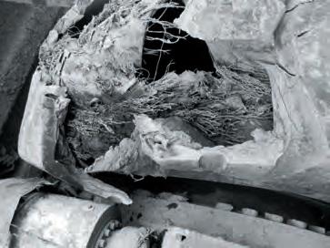
52 53 3 3
Tire Maintenance Tire Maintenance
NOTES: NHS is not for highway service. Good Condition Tread Separation Sidewall Cut Heat Separation Poor Condition
Instructions for Operations Tire Appearance Check-up
Even if tires and roads are properly maintained, tire life can be seriously shortened by improper use. The following are musts for maximum efficiency.
General:
Avoid abrupt starts and stops.
Do not operate on road shoulders.
Reduce speed on turns.
Do not turn wheels while stationary.
Do not spin tires.
Maintain proper inflation pressure.
Remove any objects, such as rocks which get stuck in the tread or between dual tires.
Check tires, rims and valves regularly for any abnormalities.
Repair any damaged tires immediately.
Avoid rocks at loading and dumping areas.
Avoid running over oil or grease spills.
Loader Operating:
Keep loading areas clear of rocks and other obstacles.
Avoid spilling load around the tires.
Avoid over-loading.
Load to the center of the dump truck's decks.
Motor Scraper Operating: Operating under Ambient Temperatures below -40°C:
Prevent tires from slipping when loading.
Avoid cornering when the pusher is in operation.
In order to prevent tire troubles, it is helpful to make routine visual check-ups of the tire, rim, valve, inflation pressure, etc. Make inspections for the following and carry out any procedure recommended.
Tire Tread:
Remove foreign matter from the tread.
Repair any damage reaching the carcass.
If separation exists, remove tire and examine if repair is necessary.
If damage reached carcass, remove tire and repair.
If cuts or chips reach carcass, repair.
Cracks in tread groove may be source of air leakage; check inflation pressure.
Uneven wear may be caused by improper inflation pressure. Rotate tires if necessary.
Damage from contact with vehicle should be avoided. Alter body parts if possible. Repair any tire damage if necessary.
Oil or grease on tire should be washed off.
Shoulder and Sidewall:
Repair any cuts reaching the carcass.
Identify cause of cracks e.g. from under-inflation, overloading, ozone or cut growth and repair if necessary.
Wash off oil or grease spots.
Valve:
Replace valve or valve parts if leakage exists from valve core, deflection of stem or extension.
Ensure valve cap is in position.
Dual Tires:
Remove any foreign object stuck between duals.
Repair stone ejector if bent or out of position.
Inflation Pressure:
Adjust if not proper.
Detect location and repair if leakage exists.
Rim:
Replace if deformation or cracks exist.
Measuring Tread Wear
Tread wear can be determined by comparing the remaining groove depth with that of a new tire. There are special marks indicating where the groove depth should be measured for most YOKOHAMA OFF-THE-ROAD TIRES. For rock or traction patterns, the indicators are located one-fourth of the tread width from the shoulders. Rib pattern tires don’t have indicators. The tread depth of rib pattern tires should be measured at the locations specified below.
The average of the figures obtained by measuring the groove depths for both the inside and outside of the tire should be used.


Tread Wear Indicator Three locations circumferentially around tire RB01 RB03 RS01 RR41 Y92 Four locations circumferentially around tire 54 55 3
3 Tire Maintenance Tire Maintenance
THE
Normal Example of tread wear indicators for typical OFF-THE-ROAD TIRES.
Consult
YOKOHAMA RUBBER CO., LTD.
Rib Pattern Tires
Tires with unique tread wear indicator locations
Ton-Kilometer-Per-Hour (Ton-Mile-Per-Hour)
Rating materials and adhesives used in tires are especially vulnerable to damage from high temperatures which limit the amount and type of usage for tires. This is especially true for OFF-THE ROAD TIRES for dump trucks and scrapers where high internal temperatures are not uncommon, because rapid dissipation of heat is hindered by the thick tire construction. Various conditions also influence the limits of use for OFF-THE-ROAD TIRES. TKPH is the measure of usage that normally indicates the limits of use under average working conditions.
Operating TKPH
Operating TKPH is computed to compare actual use with the tire's TKPH rating. The operating TKPH is calculated in the following manner by observation and measurement of actual operation.
Operating TKPH = (average tire load in metric tons) × (average speed in kilometers per hour)
Where,
Average tire load = 1/2 [(load on tire when vehicle is empty) + (load on tire when vehicle is laden)]
Average speed = (round trip distance) × (number of trips per shift) ÷ (total hours of operation per shift*)
* Exclude for calculation between shifts
For actual computation and reference this data should be collected:
Vehicle empty:
Load on front axle ÷ number of tires = tons/tire
Load on rear axle ÷ number of tires = tons/tire
Vehicle loaded:
Load on front axle ÷ number of tires = tons/tire
Load on rear axle ÷ number of tires = tons/tire
Payload = tons
Round trip distance = kilometers
Number of trips per day = times
Number of shifts per day hours of each shift
Number of shifts times
(including inspection hours, lunch hours and rest hours.)
Actual maximum speed in operation kilometers/hour
Use of TKPH Rating
With the formula described above, the operating TKPH required for a particular job can be computed and OFFTHE-ROAD TIRES which satisfy the requirement can be selected. Operating TKPH should always be less than the tire's TKPH rating. The real factor limiting tire usage is heat. TKPH measurements and ratings are only tools used to construct guidelines so that tires do not overheat. As previously started, these guidelines are constructed assuming average operating conditions. Under some conditions it is possible for more heat to be generated than would normally be expected at a given operating TKPH level. This should be kept in mind when operating TKPH approaches the tire's TKPH rating to prevent heat damage.
TMPH (Ton-Mile-Per-Hour)
Care should be taken when converting from TKPH, since TMPH uses the short ton (2,000 lbs) and mileage (1 km = 0.621 miles) and TKPH uses the metric ton (2,204.6 lbs or 1.1023 short tons). To convert TKPH to TMPH, divide TKPH by 1.459 (TMPH = TKPH ÷ 1.459).
Adjusting TKPH for Ambient Temperature
Materials, reinforcements and adhesives used in tires are vulnerable to damage from high temperatures which limit the amount and type of usage for tire. This is especially true for OFF-THE-ROAD TIRES for dump trucks and scrapers where high internal temperatures are common, because heat dissipation is hindered by the thick tire constructions. Various conditions also influence the limits of use for OFF-THE-ROAD TIRES. The “Operating TKPH” is the measure of work required from an OFF-THE-ROAD TIRE under specific conditions. The Operating TKPH should not exceed the tire's rated TKPH.
Operating TKPH is adjusted in the following manner by observation and measurement of actual operation.
Adjusted Operating TKPH = Kt × Kg × Operating TKPH
Kt : adjustment coefficient for temperature
Kg : adjustment coefficient for grade
Kt : adjustment coefficient for temperature
The TKPH tire ratings are based on an ambient temperature of 38°C (100°F). The Operating TKPH must be adjusted to compensate for a reduced or increased rate of heat dissipation to the ambient air.
For Bias Tires with maximum yearly temperature exceeding 38°C (100°F):
Kt = 77
77 + (38 − Tc)
Kt = adjustment coefficient for temperature
Tc = maximum yearly temperature in centigrade
Tc = (5 ÷ 9) × (Tf − 32)
Tf = maximum yearly temperature in fahrenheit
For Bias Tires with maximum yearly temperature less than 38°C (100°F):
Kt = 77
77+ 1 2 × (38 − Tc)
For Radial Tires with maximum yearly temperature exceeding 38°C (100°F):
Kt = 55 55+ (38 − Tc)
For Radial Tires with maximum yearly temperature less than 38°C (100°F):
Kt = 55 55+ 1 2 × (38 − Tc)
Kg : adjustment coefficient for grade
The grade of a haul road transfers load from one axel to the other of a typical haul truck. Use the chart on the following slide to determine Kg in the case of downhill loaded drive.
Mines should be designed so that the maximum grade does not exceed 10%.
TKPH of Steel Breaker
A TKPH rating is not given for steel breaker tires. However, the TKPH capability can be estimated by multiplying the TKPH rating of a comparable tire of standard construction by 0.7.
Adjustment Coefficient for Grade GradeFront KgRear Kg -1% 1.01 1.00 -2% 1.02 0.99 -3% 1.02 0.98 -4% 1.03 0.98 -5% 1.04 0.97 -6% 1.05 0.97 -7% 1.06 0.96 -8% 1.06 0.96 -9% 1.07 0.95 -10% 1.08 0.95 −1%: Downhill 1%
56 57
Tire
Tire Temperature & TKPH Rating How to get grade ?
3 3 Tire Maintenance
Maintenance
Tires
Hours per shift hours
Ambient temperature High ºC/Average ºC
distance
Dumping Area Altitude − Loading Area Altitude
from customer 2. V-Box study Consult THE YOKOHAMA RUBBER CO.,LTD.
Grade = Height Difference* ÷ One-way
*
How to get the Height difference? 1. Hearing
Load-and-Carry Operation of Front-End Loaders Protecting Tires on Vehicle in Highway Drive-Away
In loading and grading operetions with loaders and dozers, tire heat does not pose a large problem because the average operating speed is very low compared with dump trucks and scrapers. However, for load-and-carry operations the average operating speed is higher and tire temperature may become an important factor. This is especially important for the L-5 and L-5S tires which have a very thick tread. In this case, operation must be limited by the following charts. If the use of L-5 tires is too limiting, L-4 tires are an alternative.
Load & Carry Guidelines for Bias Tires
Because of the special extra-heavy construction of OFF-THE-ROAD TIRES, special precautions must be observed to protect these expensive tires when the vehicle is driven on the highway for delivery, or moved by an operator to a new job site. If the precautions are not observed, excessive tire heat may develop and the tire may fail prematurely. Always consult the vehicle or tire manufacturer for specific information before starting out on a trip. Vehicles in transit should be accompanied by responsible personnel in a pilot car to enforce the following precautions and maintain a check on equipment. This is good insurance for a large investment. The following precautions apply to tires on all vehicles in transit, driven or towed. Check the following guidelines and consult YOKOHAMA.
* When tires designed for dig and load vehicles are used in load-and-carry operations, the haul distance must be limited to 76 meters one way and maximum speed to 10kph (5 mph) Load and Pressure
Speed & Load Recommendations for Load & Carry Operations
Empty vehicles before starting.
Instructions for use of drive-away tables:
1) Determine the load each tire will carry
2) Using the table, select the inflation pressure shown for the load determined. This is the pressure required for drive-away service.
3) Ignore tire ply rating when determining driveaway load and pressure conditions.
Check inflation pressure before starting out each day and adjust to pressure recommended for highway drive-away by vehicle manufacturer
Do not drive or tow vehicles using tires with 'dry ballast' in highway drive-away.
Do not reduce inflation pressure by bleeding tires during highway drive-away. During highway driveaway pressure build-up in tires is normal.
Maximum Highway Speed
Regular Tread Tires (E-3)
Narrow Base 50 kph (30 mph)
Wide Base 30 kph (20 mph)
Average operating speed
(Running Distance ÷ (Running Hours + Stop Hours)) should be under the speed obtained by the following equation:
YOKOHAMA recommends the following mode of operation:
Stop for a 30-minute cooling period after each 2 hours of sustained operation.
A one-hour minimum stop period should be observed after every four hours of operation.
DrivingStopDriving StopDriving Stop
The following is an example for driving a vehicle on the highway for delivery:
1) Vehicle model: YOKO 155 (155 m-ton)
2) Tire size: 36.00-51 66PR E-3
3) Temperature: 10ºC~38ºC (50ºF~100ºF)
4) Tire load: Empty before starting, load on front tire 29.5 m-ton (32.5 s-ton)
5) Inflation pressure: 515 kPa (75 psi)
6) Maximum speed: 50 kph (30 mph)
7) Average speed:
Where narrow base and wide base tires are mixed on a vehicle, use the guidelines specified for wide base tires.
Deep Tread (E-4) & Special Compound Tires
Do not drive vehicles equipped with deep tread (E-4) and special compound tires over the highway unless the proposed trip is reviewed and approved by qualified YOKOHAMA personnel.
Extra Deep Tread Tires
Do not under any circumstances move extra deep tread tires over the highway.
8) Recommended Operation Mode:
YOKOHAMA Pattern Code TRA Code Tire Spec Ton-MileageAverage Speed TMPHTKPHMPHKPH Y565E-3 RE-T50073012.3119.80 HR-V60087514.7723.73 YOKOHAMA Pattern Code TRA Code Tire Spec *Speed V) MPH KPH Y565E-3 RE-T16.92 27.22 HR-V20.31 32.63 2H Driving 0.5H Stop 2H Driving 1H Stop 2H Driving 0.5H Stop 2H Driving 1H Stop Speed V) Speed (V Speed V) Speed (V) 58 59 3 3
Tire
Tire Maintenance
Maintenance
Operation Mode
Speed = *Speed = Average Speed × = Average Speed × (5.5 ÷ 4) 0.8 is a safety coefficient. × 0.8 Tire TKPH Driving Hours + Stop Hours Tire Load (M-Ton) Driving Hours TRA Code Air Pressure for Front Tires Maximum One Way Distance Average Work day Speed ~29” ~33” ~45” L-3 Standard A.P. +100kPa (+15psi) 610m (2000ft.)11km/h (7 mph) – –L-4 244m (800ft.) 9km/h (6 mph)7km/h (4 mph)5km/h (3 mph) * L-5 76m (250ft.) 7km/h (4 mph)5km/h (3 mph)3km/h (2 mph) Max. Speed % Load Change From 5MPH Table 10km/h (5 mph) No Change 15km/h (10 mph) –13% 25km/h (15 mph) –20%
2H0.5H2H1.0H2H0.5H
Protecting Tires on Vehicle in Highway Drive-Away
Load and Inflation Pressure Table for Transit (as recommended by the TRA)
Narrow Base Earthmover Tires in Drive-Away Service Only
50 KPH (30 MPH) Maximum speed
Wide Base Earthmover Tires in Drive-Away Service Only
50 KPH (30 MPH) Maximum speed
* Tire size designation will include"R"(Radial Ply) or "-"(Diagonal or Bias Ply)
**Not available from THE YOKOHAMA RUBBER CO.,LTD.
NOTES: Figures are subjected to change without prior notice.
* Tire size designation will include"R"(Radial Ply) or "-"(Diagonal or Bias Ply)
**Not available from THE YOKOHAMA RUBBER CO.,LTD.
NOTES: Figures are subjected to change without prior notice.
60 61 3 3 Tire Maintenance Tire Maintenance
PSI × 0.0703 = kg/cm POUND × 0.4536 = kg PSI × 6.895 = kPa
Handling of Tires Safety Precautions for Mounting Safety Precautions for Demounting
Improper handling of tires can lead to damage, especially to the beads. Therefore, it is necessary to prevent excess pressure from being exerted on the beads.
When using a forklift to lift a tire: Mounting
Lay the tire vertically across the fork, or
Use a round fork at least six-inches in diameter. Do not insert a flat type fork within the tire.
When lifting tires by crane:
Use a wide nylon or rubber sling.
Do not hook the tire beads.
Do not use a rope sling.
Safety Precautions
WARNING
Tire and rim servicing can be dangerous, and should be performed only by trained personnel using proper tools and procedures. Failure to comply with these procedures may result in faulty positioning of the tire and/or rim, and cause the assembly to burst with explosive force, sufficient to cause serious physical injury or death.
Demounting
1. Before Demounting
Always exhaust all air from a single tire and from both tires of a dual assembly prior to removing any wheel components such as nuts and rim clamps. A broken rim part under pressure can blow apart and cause serious injury or death.
Make sure to remove valve core to exhaust all air from the tire. Remove both cores from a dual assembly. (When you remove the wheel lugs, if the tire is still under pressure, the assembly may fly apart.)
Check the valve stem by running a piece of wire through the stem to make sure it is not plugged. (Foreign material may clog the valve stem during deflation or ice may form as the air leaves the tire, clogging the valve stem.)
2. During Demounting
Demounting tools apply pressure to rim flanges to unseat tire beads, and keep your fingers clear Always stand to one side and hold the tool with one hand when you apply hydraulic pressure. (If the tool slips off, it can fly with enough force to cause serious injury or death.)
Do not use tools in the vicinity of the flange butt weld.
3. After Demounting
Clean rims and repaint to stop detrimental effects of corrosion and facilitate checking and tire mounting. Be very careful to clean all dirt and rust from the lock ring and gutter. This is important to secure the lock ring in its proper position. A filter on the air inflation equipment to remove the moisture from the air line helps prevent corrosion. The filter should be checked periodically to see that it is working properly. (Parts must be clean for a proper fit - particularly the gutter section which holds the lock ring in its proper position.)
1. Before Mounting
Check rim components for cracks. Replace all cracked, badly worn, damaged and severely rusted components with new parts of the same size and type. When a component is in doubt, replace it. (Parts that are cracked, damaged or excessively corroded are weakened. Bent or repaired parts may not engage properly.)
Do not, under any circumstance, attempt to rework, weld, heat or braze any rim component that is cracked, broken or damaged. Replace with a new part that is not cracked, broken or damaged and which is of the same size and type. (Heating may weaken a part to extent that it is unable to withstand forces of inflation or operation.)
Check type of rim and make sure all parts of such rim are being assembled properly. Follow instruction manual of rim or ask your distributor if you have any doubts.(Mismatched parts may appear to fit, but when the tire is inflated they may fly apart with explosive force.)
Mixing parts of one type rim with those of another is potentially dangerous. Always check rim with manufacturer for approval.
Remove rust, dirt and other foreign matter from the rim surface, particularly on the bead seats and O-ring slot.
Clean the inside of the tire
Make sure tube and flap are correct and not damaged for tube type tires.
Always prepare a new O-ring for tubeless tires. Do not reinflate a tire that has been run flat or has been run at 80% or less of its recommended operating pressure, or when there is obvious or suspected damage to the tire or wheel components. (Components may have been damaged or dislocated during the time the tire was run flat or seriously under-inflated.)
2. During Mounting and Inflation
Do not try to seat rings or other components by hammering while tire is inflated or partially inflated
Double check to make sure all components are properly seated prior to inflation. Do not inflate tire before all components are properly in place. Place in safety cage or use a restraining device and inflate to approximately 0.35 kg/cm2 (5 psi), recheck components for proper assembly. Observe that O-ring does not roll out of its groove. If assembly is not performed properly, deflate and correct. Never hammer on an inflated on partially inflated tire/rim assembly. If assembly is correct at approximately 0.35 kg/cm2 (5 psi), continue to inflate fully to seat the tire beads. Never sit or stand in front of a tire and rim assembly that is being inflated. Always use a clip-on chuck with a sufficient length of hose to permit the person inflating the tire to stand clear of the potential trajectory of the wheel components, and use an in-line valve with gauge or a pressure regulator preset to a desired value when inflating a tire. When a tire is in a restraining device, do not lean any part of your body or equipment on or against the restraining device. (If parts are improperly installed they may fly apart with explosive force.)
Never attempt to weld on an inflated tire/rim assembly or on a rim assembly with a deflated tire. (Heat from welding will cause a sudden, drastic increase in pressure, resulting in an explosion with the force of a bomb. Deflated tires can catch fire inside the air chamber.)
3. After Inflation
Make sure no air leakage can be suspected, especially in tubeless tires.
Good Good Bad Good Bad Bad 62 63 3 3
Tire Maintenance
Tire Maintenance
Safety Precautions for Operation
Operation
Do not use under-inflated tires.
Do not bleed or reduce air pressure to compensate for the increase in pressure resulting from operation. Do not use under-size rims. Use recommended rim for the tire.
Do not overload or over-inflate tire/rim assemblies. Check for adequate rim strength if special operating conditions are required. (Excessive overload can cause damage to the tire and rim assembly.)
Never run a vehicle on one tire of a dual assembly. (The carrying capacity of the single tire and rim is dangerously exceeded, and operating a vehicle in this manner can result in damage to the rim and tire or cause a tire fire.)
Never use a tube in a tubeless tire/rim assembly where the rim is suspected of air leakage. (Loss of air pressure through fatigue cracks or other fractures in a tubeless rim warns you of a potential rim failure. This safety feature is lost when tubes are used with leaking rims. Continued use may cause the rim to burst with explosive force.)
Always inspect rims and wheels for damage during tire checks. (Early detection of potential rim failure may prevent serous injury.)
Never add or remove an attachment or otherwise modify a rim (Especially by heating, welding or brazing) unless the tire has been removed and approval has been received from the rim manufacturer. (Modification or heating of a rim or one of its parts may weaken it so that it cannot withstand forces created by inflation or operation.)
Never mount bias tire and radial tire on the same axle. Follow vehicle manufacturer's recommendation.
Never use tire under unintended service conditions for the tire. Please consult YOKOHAMA if vehicle operation requires specialized tire fitment.
Tire Storage How to Reduce Tire Costs
In general, tires should be removed from the rim, cleaned, and stored in a cool, dry room. They should be stored in an upright position, not horizontally, so that the proper space between the beads will be maintained. Make sure that the tire is not deformed by any external pressure exerted on it.
Avoid the following when storing tires:
Direct sunlight. Ozone.
Oil and grease.
High temperatures and humidity.
If tires must be stored outside, cover them with a tarpaulin for protection. If a vehicle is stored with tires mounted, rest the vehicle on blocks to relieve the load on the tires. Deflate the tires and cover them. Rotate the tires once a month to prevent permanent deformation, if the vehicle cannot be rested on blocks. Tools for Mounting and Demounting Tires
The following are all portable tools, and can be used both horizontally and vertically.


Select the proper tire for the job:
Tire size.
Ply rating.
Tire specification.
Maintain a tire record
Keep a tire card for each tire.
Analyze scrap tires.
Carry out good tire maintenance:
Perform regular inflation pressure checks.
Regularly inspect tire appearance.
Ensure proper matching of dual tires.
Prevent oil saturation.
Prevent high temperature and humidity.
Prevent wavy condition.
Keep haul road, loading and dumping area clean.
Provide good drainage.
Maintain good job conditions:
Do not overload.
Avoid excessive speed.
Train operator.
Bad Good 64 65 3 3
Tire Maintenance Tire Maintenance
Hydraulic tire remover (tire push type) and bead wedges. Commonly used for 25 inch rims. Hydraulic tire remover (tire push type) in operation Hydraulic tire remover (rim flange push type). Commonly used for 33 inch or larger rims. Hydraulic tire remover (rim flange push type) in operation Tire handler
Tube type tires employ tubes to retain air under pressure within the carcass. The flap is a liner which is placed between the rim and tube to protect the tube from damage by the rim and beads. The size of the tube and flap are usually indicated by the size of tire for which they can be used, without regard for the ply rating. For example, a 23.5-25 size tube or flap can be used with a tire of 23.5 inch width and a diameter of 25 inches. Some tubes and flaps can be used for more than one size of tire. For example, a size 13.00-24 and 13.00-25.
Storage of Tubes and Flaps
Tubes and flaps should be cleaned and all of the air expelled before storage. They should always be stored in a dry, cool place. The tubes should be packed lightly when storing to prevent the metal valve stems from causing damage.
Valves for Tube Type Tires
The type of valve used for a tube type tire depends on the type of rim it is mounted to. Therefore, when purchasing tubes, proper attention should be given to the valve type.
Tubes and Flaps Rims
Normally, a rim is composed of a rim base, two side flanges (or side rings), bead seat band and lock ring. On some smaller size rims, parts may be joined. For tubeless tires, an O-ring is also used.
Type of Rims
Tires can function properly only when they are mounted on the right rim. There are four basic types of rims for OFF-THE-ROAD TIRES: flat base, full tapered bead seat, semi-drop center and drop center.
Flat Base Type Rims
There are two sub-classifications of interchangeable flat base type rims as shown below. A tire which fits on one kind of flat base rim will fi t on all flat base rims of the same width and diameter. These rims are used for relatively small tube type OFF-THE-ROAD TIRES.
Rim Identification
Rims are normally identified by a three-part code consisting of rim width (inches), flange shape (alphabetical) and rim diameter (inches). A flat base rim example would be: 9.00 V x 24. This follows the nomenclature of tire size with the addition of the flange identification, in this case. The code for full tapered bead seat rims does not indicate the flange shape, but some indicate flange height in inches. An example would be 17.00 x 252.0, where 2.0 is the flange height in inches.
Full Tapered Bead Seat Rims
Most large-wheeled construction machinery employ full tapered bead seat rims. These rims have a 5º taper in the bead seat which strengthens the rim/bead binding. Additionally, a fine groove called "knurling" lines the bead surface to prevent further slippage. Flat base rims have a looser fit and some slippage may occur under quick acceleration if used on the same large-wheeled vehicle. Almost all rims with diameters over 25" are full tapered bead seat types. Wide base variations are also available.
Drop Center Rims (DC)
The drop center rim also has a 5º-inclined bead seat, but with a deeply depressed center (dropped rim center) section for easier tire mounting. Most DC rims are used on small loaders.
Semi-Drop Center Rims (SDC)
This rim has a 5º-inclined bead seat and a depressed center. It is abbreviated as the "SDC" rim. Most SDC rims for OFF-THE-ROAD TIRES have diameters of 20" or 24". They are used on graders and loaders, and are identified by the marking on the tire sidewall: "For SDC RIM" or "For SDC RIMS".
Caution with Wheel Use
Wheel defects such as cracks or corrosion can lead to air leakage, causing among other dangers, deteriorated traction and braking performance. Service life of the tire will degrade, also. More importantly, safe operation of the vehicle will be jeopardized.
Do not use wheels with defects such as corrosion or cracks.
Do not use rims for tubeless application that have been welded, have rust or have air leakage. Do not use wheels with cracks, breakage or rust erosion on the nut seat of the wheel.
Do not use wheels if packing gutters are deformed by rust.
Do not re-use O-rings.
66 67 4 4 Rims, Valves & O-rings Rims, Valves & O-rings
Valves
Valves for OFF-THE-ROAD TIRES are of two types, tube or rim valves and are available in three makes: standard bore, large bore and air/water. Tube valves are for tube type tires and rim valves are for tubeless type tires.
Tube Valves
(1) Standard Bore Tube Valves
This valve has an opening to accommodate a standard valve core. This type of valve is mainly used for tires smaller than 14.00-24.
(2) Large Bore Tube Valves
More air is required to fill larger tires. To decrease the filling time, a large bore valve can be utilized due to its increased internal diameter. This type of valve is used for wide base and narrow base tires with tread widths larger than 15.5 and 16.00, respectively. The large bore valve is also called a "jumbo valve", for which the third letter of its part number stands for.
(3) Air/Water Tube Valves
A liquid compound (normally a calcium chloride solution) can be injected into a tube with this valve. Two types are available, the TR218A and TR220A.
Rim Valves
(1) Standard Bore Rim Valves
This is the rim valve counterpart to the standard bore tube valve explained on the opposite page.
(2) Large Bore Rim Valves
This is a rim valve with a large valve core, corresponding to the large bore tube valve. There are three types available.
Valve Core: TRCa (short core only)
* Recommended torque at installation: 70-80 inch-pound
68 69 4 4 Rims, Valves & O-rings Rims, Valves & O-rings
Rim Valves
(3) Air/Water Rim Valves
This is a rim valve with a core housing, corresponding to its tube valve type explained previously. There are four types of these valves available: TR618A, TR621A, TR622A and TR623A.
TR618A Dimensions
(4) Super Large Bore Rim Valves
Super large bore rim valves have an internal diameter
50% larger than large bore valves which makes air inflation easier and faster.
TRL850 Length (Swivel Type) Dimensions
(5) Caution with Tubeless Air Valves
Whenever the tubeless tire is demounted and changed, the tubeless air valve (rim valve) must be replaced with a new one, regardless of appearance.
TR621A, TR622A and TR623A Dimensions
TRL890 Length (Turret Type) Dimensions
Extension
Semi-flexible Extension
NOTES: Valves for inside dual-pair tire are equipped with a supplemental valve extension to facilitate air inflation. The extension is made of brass which is apt to nicks, scratches and dents. Care is required when (de)mounting, and storage should be in a clean, moisture free area.
70 71 4 4
Rims, Valves
Rims, Valves & O-rings
& O-rings
O-rings
Rims for tubeless OFF-THE-ROAD TIRES require the use of an O-ring. Also referred to as a "seal ring" or "gasket", the O-ring forms an air-tight seal between separate parts of the rim. It must be used properly. It is very important to note that even if rim diameters are the same, different size O-rings may be necessary depending on the type of rim used.
O-ring Structure
SDC: semi-drop center rim TB: tapered bead seat rim
O-ring identification
OR 3 25 T Type of rim (Full tapered bead seat rim)
Rim diameter (Bead diameter in inches)
Cross section diameter O-ring (in eights of an inch)
Indicates that the ring is for OFF-THE-ROAD TIRES
Caution with O-rings
Do not use used or damaged O-rings.
Clean rim and then lubricate with vegetable oil before mounting the O-ring.
Take caution not to damage O-ring with tire lever.
Avoid twisting.
Keep spare O-rings on hand for emergencies. A 20% backup rate is recommended.
4 4
Valves & O-rings Rims, Valves & O-rings 72 73
Rims,
O-ring No. Rim Tire Section Diameter Inside Circumference mm inch mm inch OR224TG 24” SDC 24” rim diameter 6.7 0.26 1768 69.61 OR225T 25” SDC 14.00-25 and under 6.7 0.26 1802 70.94 25” TB 17.5-25 and under 20.5-25(use 17.00×25-1.7
OR325T 25” TB 16.00-25 and over 20.5-25(use 17.00×25-2.0 rim)and over 9.8 0.39 1800 71.06 OR329T 29” TB 29” rim diameter 9.8 0.39 2127 83.74 OR333T 33” TB 33” rim diameter 9.8 0.39 2447 96.34 OR335T 35” TB 35” rim diameter 9.8 0.39 2560100.79 OR339T 39” TB 39” rim diameter 9.8 0.39 2868112.91 OR345T 45” TB 45” rim diameter 9.8 0.39 3311130.35 OR349T 49” TB 49” rim diameter 9.8 0.39 3572140.63 OR451T 51” TB 51” rim diameter 12.7 0.5 3666144.33 OR457T 57” TB 57” rim diameter 12.7 0.5 4103161.54
rim)
Combination Tables
OFF-THE-ROAD TIRES, Tube, Flap and O-ring Combination Table
OFF-THE-ROAD TIRES, Tube, Flap and O-ring Combination Table
The valve sizes for tubes and rims shown in tables (p.74-75) correspond with the conventional standards of TRA,JATMA, etc.
74 75 4 4
Rims,
Rims, Valves & O-rings
Valves & O-rings
PSI × 0.0703 = kg/cm POUND × 0.4536 = kg PSI × 6.895 = kPa PSI × 0.0703 = kg/cm2 POUND × 0.4536 = kg PSI × 6.895 = kPa
Tire Size Tube Size Valve Size Flap Size O-ring Size Tube Valve Rim Valve 9.00-20 9.00-20 TR175A,TR76A 8.25/9.00 R 20 10.00-20 11.1/10.00 R)20TR78A,TR76A 10.00/11.1 R 20 11.00-20 11.00-20 TR78A,TR76A 11.00/12.00 R 20 12.00-20 12.00-20 TR78A,TR76A 11.00/12.00 R 20 14.00-20 14.00-20 TR179A,JS179 13/80,13.00/14.00/15.0 R 20 12.00-24 11.00/12.00 R)24TR78A,TR77A TR618A,TR503A10.00/11.00/12.00-24 13.00-24 13.00-24/25TR77A,JS179A TR618A,TR503A13.00/14.00-24/25 OR224TG 14.00R24 14.00 R)24/25JS179 TR618A 13.00/14.00-24/25 OR224TG 14.00-24 14.00-24/25TR77A,TR175A,TR179ATR618A,TR503A13.00/14.00-24/25 OR224TG 16.00-24 16.00-24/25JSJ1175B,JSJ1175TR618A,TR503A16.00/18.00-24/25 OR224TG 14.00R25 14.00-24/25TR77A,TR175A,TR179ATR508,TR650 13.00/14.00-24/25 OR225T 14.00-25 14.00-24/25TR77A,TR175A,TR179ATR508,TR650 13.00/14.00-24/25 OR225T 16.00R25 TRJ650,TRJ670,TRJ690 OR325T 16.00-25 16.00-24/25JSJ1175B,JSJ1175TRJ650,TRJ670,TRJ69016.00/18.00-24/25 OR325T 18.00R25 TRJ650,TRJ670,TRJ690 OR325T 18.00-25 18.00-24/25JSJ1175B,JSJ1175CTRJ650,TRJ670,TRJ69016.00/18.00-24/25 OR325T 21.00-25 21.00-24/25JSJ1175 TRJ650,TRJ670,TRJ69021.00-24/25*15.5/17.5-25OR325T 24.00-25 24.00-25 JSJ1175 TRJ650,TRJ670,TRJ69020.5/24.00-25 OR325T 24.00-29 TRJ650,TRJ670,TRJ690 OR329T 18.00R33 TRJ650,TRJ670,TRJ690 OR333T 18.00-33 TRJ650,TRJ670,TRJ690 OR333T 21.00-35 TRJ650,TRJ670,TRJ690 OR335T 24.00R35 TRJ650,TRJ670,TRJ690 OR335T 24.00-35 TRJ650,TRJ670,TRJ690 OR335T 24.00-49 TRJ650,TRJ670,TRJ690 OR349T 27.00R49 TRJ650,TRJ670,TRJ690 OR349T 27.00-49 TRJ650,TRJ670,TRJ690 OR349T 30.00-51 TRJ650,TRJ670,TRJ690 OR451T 33.00R51 TRJ650,TRJ670,TRJ690 OR451T 33.00-51 TRJ650,TRJ670,TRJ690 OR451T 36.00-51 TRJ650,TRJ670,TRJ690 OR451T 40.00-57 TRL870,TRL850 OR457T Tire Size Tube Size Valve Size Flap Size O-ring Size Tube Valve Rim Valve 12.5/70-16 TR575,TR415 10-16.5 10-16.5 TR15 TR575 17.5/65-20 17.5/65-20 TR218A TR618A 14/70-20 14/70-20 TR179A 14/70-20 13.5-20 13.5-20 TR78A 13.5-20 15.0-20 15.0-20 TJ179W 15.0-20 42×17-20 42×17-20 TR179A 42×17-20 16.9-24 16.9-24 TR218A TR618A 18.4-24 18.4-24 TR218A TR618A 750/65R25 TRJ650,TRJ670,TRJ690 OR325T 15.5-25 15.5-25 JSJ1175B,JSJ1175TRJ650,TRJ670,TRJ69015.5/17.5-25 OR225T 17.5R25 TRJ650,TRJ670,TRJ690 OR225T 17.5-25 17.5-25 JSJ1175B,JSJ1175TRJ650,TRJ670,TRJ69015.5/17.5-25 OR225T 20.5R25 TRJ650,TRJ670,TRJ690 OR325T/OR225T 20.5-25 20.5-25 JSJ1175B,JSJ1175TRJ650,TRJ670,TRJ69020.5-25 OR325T/OR225T 23.5R25 TRJ650,TRJ670,TRJ690 OR325T 23.5-25 23.5-25 JSJ1175B,JSJ1175TRJ650,TRJ670,TRJ69023.5-25 OR325T 26.5R25 TRJ650,TRJ670,TRJ690 OR325T 26.5-25 26.5-25 JSJ1175 TRJ650,TRJ670,TRJ69026.5-25 OR325T 29.5R25 TRJ650,TRJ670,TRJ690 OR325T 29.5-25 TRJ650,TRJ670,TRJ690 OR325T 875/65R29 TRJ650,TRJ670,TRJ690 OR329T 26.5-29 TRJ650,TRJ670,TRJ690 OR329T 29.5-29 TRJ650,TRJ670,TRJ690 OR329T 33.25-29 TRJ650,TRJ670,TRJ690 OR329T 35/65-33 TRJ650,TRJ670,TRJ690 OR333T 29.5-35 TRJ650,TRJ670,TRJ690 OR335T 33.25-35 TRJ650,TRJ670,TRJ690 OR335T 37.25R35 TRJ650,TRJ670,TRJ690 OR335T 37.25-35 TRJ650,TRJ670,TRJ690 OR335T 37.5-39 TRJ650,TRJ670,TRJ690 OR339T 40/65-39 TRJ650,TRJ670,TRJ690 OR339T 45/65-45 TRJ650,TRJ670,TRJ690 OR345T 325/95R24 325/95(R)24TR77A,TR78A,JS179 325/95R24 385/95R25 TRJ650 OR225T 445/95R25 TRJ650,TRJ670,TRJ690 OR325T 480/95R25 TRJ650,TRJ670,TRJ690 OR325T 505/95R25 TRJ650,TRJ670,TRJ690 OR325T 525/80R25 TRJ650,TRJ670,TRJ690 OR325T
Earthmover Data
Formulas and Rules
The following are useful formulas and rules of thumb:
Production, hourly = Load (BCY)/Cycles × Cycles/hr
= Load (BM3)/Cycles × Cycles/hr
Load factor (L.F.) =
Usable pull (traction limitation) = Coeffective of traction × Weight on drivers = Coeffective of traction × (Total weight × % on drivers)
Pull required = Rolling resistance + Grade resistance = Total resistance
Load (bank measure) = Loose cubic yards (LCY) × L.F. = Loose cubic meters (LM3) × L.F.
Cycles per hour =
Load (bank measure) =
Rolling resistance factor = 40 lbs/ton + (30 lbs/ton/inch × inches)
20
+ (15 kg/ton/2.5 cm × cm)
Rolling resistance = 2% of GVW* + 1.5% of GVW × inch of tire penetration = 2% of GVW + 0.6% of GVW × cm of tire penetration
*GVW = Gross Vehicle Weight
Grade resistance factor (GR factor) = 20 lbs/ton × % of grade = 10 kg/ton × % of grade
Grade resistance = GR factor (lbs/ton) × GVW (tons) = GR factor (kg/ton) × GVW (tons)
Grade resistance = 1% of GVW × % of grade
Rolling Resistance (%) = 2% + 1.5% per inch of tire penetration = 2% + 0.6% per cm of tire penetration
76 77 5 5
Miscellaneous Data Miscellaneous Data
Total resistance = Rolling resistance (lbs or kg) + Grade resistance (lbs or kg)
=
kg/ton
Load
(L.F.)
Load factor (L.F.) = Bank cubic yards (BCY) Weight of Load 60 minutes Bank cubic meters (BM3) 100% Loose cubic yards (LCY) Bank density Total cycle time (minutes) Loose cubic meters (LM3) 100% + % of swell
(S.F.)
Bank cubic
factor
=
Shrinkage factor
= Compacted cubic yards (CCY)
yards (BCY)
Density = Weight/Unit volume
(%) = % of grade
grade (%) = PR (%) + GR (%) Total cycle time = Fixed time + Variable time Fixed time: Refer to respective machine production section. Variable time = Total haul time + Total return time Adjusted productivity = Hourly productivity × Efficiency factor Compacted cubic meters (CM3) Bank cubic meters (BM3) Travel time = Distance (ft) Speed (ft/min) Travel time = Distance (m) Speed (m/min) No. of units requires = No. of scrapers a pusher will load = Hourly production required Unit hourly production Scraper cycle time Unit hourly production
Shrinkage factor (S.F.) =
Grade
Effective
Earthmover Data Conversion Tables
Various tire sizes and inflation pressures will greatly reduce or increase the above figures. The quantities given are sufficiently accurate for estimating purposes when specific information on performance of particular equipment on given soil conditions is not available. See other Earthmoving Data Section tables for additional information. Metric to Standard (UK, US, etc.)
Approximate Coefficient of Traction Factors
*Varies with moisture content, grain, size, degree of compactness, etc. Tests must be made to determine exact material characteristic.
Swell-Voids-Load Factor Table
1 km = 1,000 m 1m = 100 cm 1 cm = 10 mm 1 km2 = 100 Ha
1 Ha = 10,000 m2 1 m2 = 10,000 cm2 1 cm2 = 100 mm2
1 m3 = 1,000 liters 1 liters = 1,000 cm3
1 metric ton = 1,000 kg 1 quintal = 100 kg 1 kg = 1,000 g
1 Cal = 427 kgm = 0.0016 CVH = 0.00116 KWH
1 kg/cm2 = 98.066 kPa Torque unit: 1 CV = 75 kgm/sec
1 kg/cm2 =0.97 atmosph 1 bar = 100 kPa
Standard (UK, US, etc.) to Metric
*Semi-skeleton shoes = .27
Swell-Voids-Load Factor Table
1 mile = 1,760 yds 1 yd = 3 ft 1 ft = 12 in 1 sq mile = 640 acres
1 acre = 43,560 sq ft 1 sq ft = 144 sq in 1 cu ft = 7.48 gal
1 gal = 231 cu in = 4 quarts liq 1 quart = 32 fl oz 1 fl oz = 1.80 cu in
1 sh ton = 2,000 lbs 1 lg ton = 2,240 lbs 1 lb = 16 oz, avdp.
1 BTU = 778 ft lb = 0.000393 HPH = 0.000293 KWH
1 HP = 550 ft lb/sec 1 atmosph = 14.7 psi
78 79 5 5
Miscellaneous Data Miscellaneous Data
Typical Rolling Resistance Factors Material* Swell Percentage & Load Factors Inches to Millimeters Millimeters to Inches
*Varies with moisture content, grain, degree of compactness, etc. Tests must be made to determine exact material characteristics.
80 81
Weight
Materials* Pounds to Kilograms Kilograms to Pounds Miles Per Hour to Kilometers Per Hour Kilometers Per Hour to Miles Per Hour Temperature (Centigrade to Fahrenheit) Grade in Degrees to Grade in Percent Inflation Pressure (kg/cm2 to lbs/in2) R: Rock, E: Earth
Conversion Tables Approximate
of
5 5 Miscellaneous Data Miscellaneous Data
