
1 GEORGIA INSTITUTE OF TECHNOLOGY YINING ANNIE CHEN PORT FOLIO 2020 | 2023 ART | SPACE | FORM
POINT, LINE, PLANE- FROM TWO DIMENSION TO THREE DIMENSION MUSIC HOUSE- MODELS FUSION MOTIF
DIGITAL DRAWING- SPACE COMPLEX
DIGITAL DRAWING- MATHEMATIC FORM
PARAMETRIC BUILDING SYSTEM- CASE STUDY OF TOKYO AOYAMA
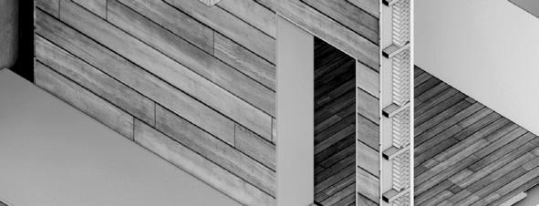


FORM EVOLUTION- GRASSHOPPER ANIMATION
WIND PAVILLION-VR INTERACTION IN DESIGN
DRAGONBOT- CREATE MICROCLIMATE ABOVE THE HINMAN COURTYARD
BUZZ STATION- BUS STOP ON GEORGIA TECH CAMPUS OFFICE BUILDING CONSTRUCTION IN BOSTON- ARCHITECTURE STRUCTURE MEP
EXPERIENTIAL INTIMACY- A PLAY WITH VIRTUAL REALITY HOLOLENS REBAR REVIVAL- TRASH TO TREASURE
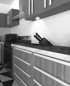
KITCHEN SAFETY OF OLDER ADULTS- ELDERS’ UNIVERSAL KITCHEN RESEARCH
BREAKING THE BOX- CONFINED SPACE X REBELLIOUS MOVEMENT

CONTENTS CONTENTS TABLE OF TABLE OF 01 03 04 05 06 02 ART | SPACE | FORM ART | SPACE | FORM 01. STUDIO ARCHITECTURE PROJECT 02. DIGITAL PROGRAMMING 03. STRUCTURE &TECHNOLOGY 04. CONSTRUCTION & FABRICATION 05. RESEARCH &DESIGN PRODUCT 06. INTERDISCIPLINARY ARTS WORK CATAGORIES 01 02 03 04 05 06
4- 6 7- 9 26- 27 28- 77 84- 85 86-91 78- 79 80-83 11 12- 13 14- 17 18- 19 20- 21 22- 25
p. 04 p. 11 p. 26 p. 78 p. 84 p. 86
FROM TWO DIMENSION TO THREE DIMENSION
Course: Core Studio I
Instructor: Charles Rudolph Fall 2020
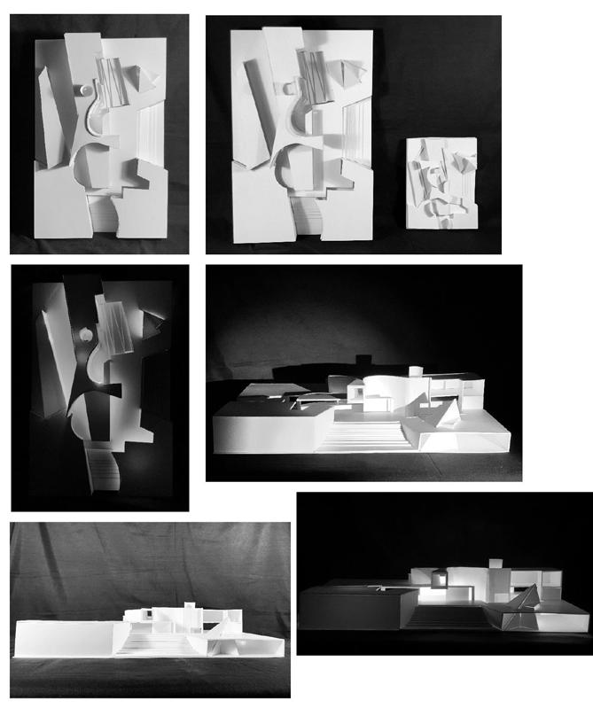
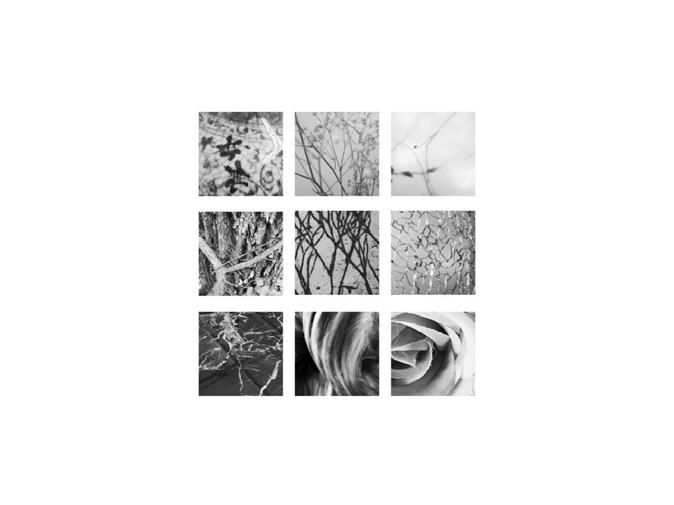
This exercise begins a sequence of exploratory activities in abstraction involving photography, drawing, and modelmaking. Each part of the sequence will derive from the one before it and apply both translations, which include a photo to sketch, drawing to model, and iteration, which involves making multiples). In each step of the sequence of design explorations. The following conditions are present in work:
DIFFERENCE / REPETITION FIGURE / FIELD CENTER / EDGE MOVEMENT / STASIS TENSION / REPOSE OPEN / CLOSED
The exploration involves selecting three photos from the group of nine and undergoing a translation process into a line-based drawing, one for each image. The media used for the pictures is a soft drawing pencil. Each illustration is 6” x 6” square on Bristol paper. Experiment using the iterative method, using tracing paper in overlays to test visual and compositional ideas. Use various lines’ values to achieve depth, transition, variety, etc. Experiment with compositions refers to the list of “dualities”.
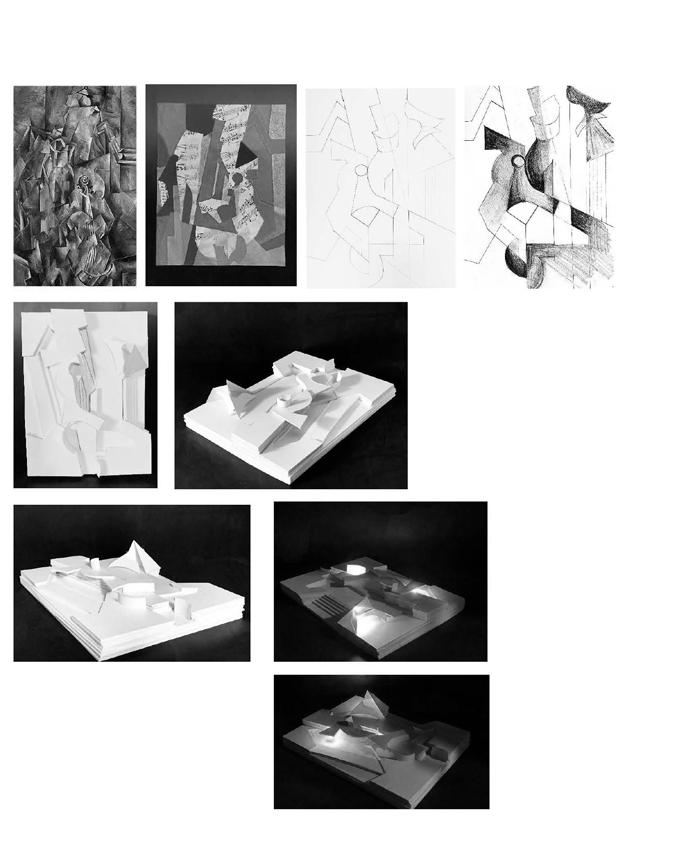


The final stage is a translation from two-dimensional drawings to three- dimensional model. Transforming the abstractions of lines and spaces on the flat paper surface to the construction of characters that shape space is a step into architecture–although the critical dialogue of abstraction is maintained and intensified.
PHOTOGRAPHY, DRAWING, MODEL #2 PAINTING AS SITE
POINT, LINE, PLANE 4 5
POINT, LINE, PLANE
PHOTOGRAPHY, DRAWING, MODEL #1
THE SOLUTION TO “KIT OF PARTS”
This corner park aims to provide a seggregated and tranquil space in the center of downtown city. The outside high wall ensures the pri-vate-intimate interior space. All long and thin kit of parts functions for tectonic use. The paths which lead to the center activity spaces are narrow just so the a sense of mystery is increased when travers-ing through the paths. An open large courtyard in the center is open for public gathering, and two smaller chambers for priviate gathering are parallel to each other. The pavillion-like structures casts a good amount of shades and shelters for visitors.
MUSIC HOUSE
MODELS FUSION MOTIF
Course: Core Studio


Instructor: Charles Rudolph Fall 2020
Brief Introduction
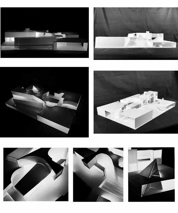
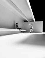
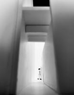
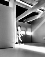
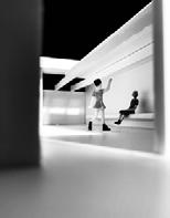
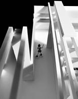
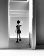
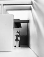
This project combines previous models No. 2 and 3, and the site is Lancaster Community Park, Millersville Pike, Lancaster, PA, 1.5 miles and 8 minutes driving to Fulton Theatre for the final design. The model for the corner park is to be rotated 90 degrees. The “ground” becomes a vertical wall. The wall is altered but remains a structural entity that supports stairs and floors. The House negotiates the given forms and spaces of the site. The House aims to provide a comfortable living space for Broadway actors/actresses to spend their vacations, hold after-parties, and socialize with his/her friends.


The highlight of the House is an interior stage at the negative four level and an outdoor stage on the ground level connected by a circulation through the backstage. The backstage in between the circulation is a versatile space that could function as a place for make-up, storage, socializing, and a transitional space to the upper level.


MODEL #3 KIT OF PARTS

POINT, LINE, PLANE 6 7
INTERIOR, EXTERIOR RENDERS


MUSIC HOUSE MUSIC HOUSE 8 9
ELEVATION, SECTION NE SW NW SE
PROJECTIVE GEOMETREY DIGITAL DRAWING
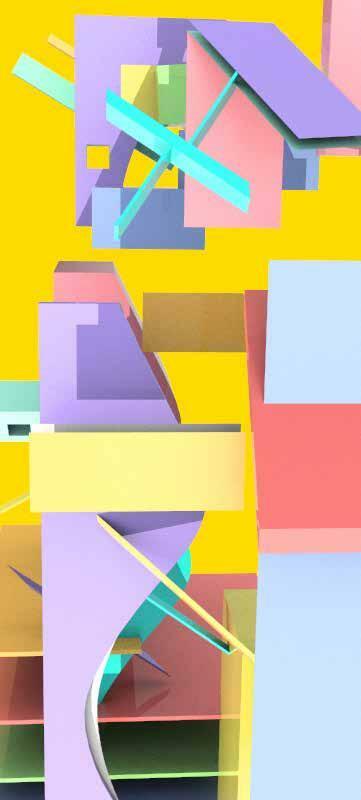


Motif: Libeskind “Micromegas” Drawing
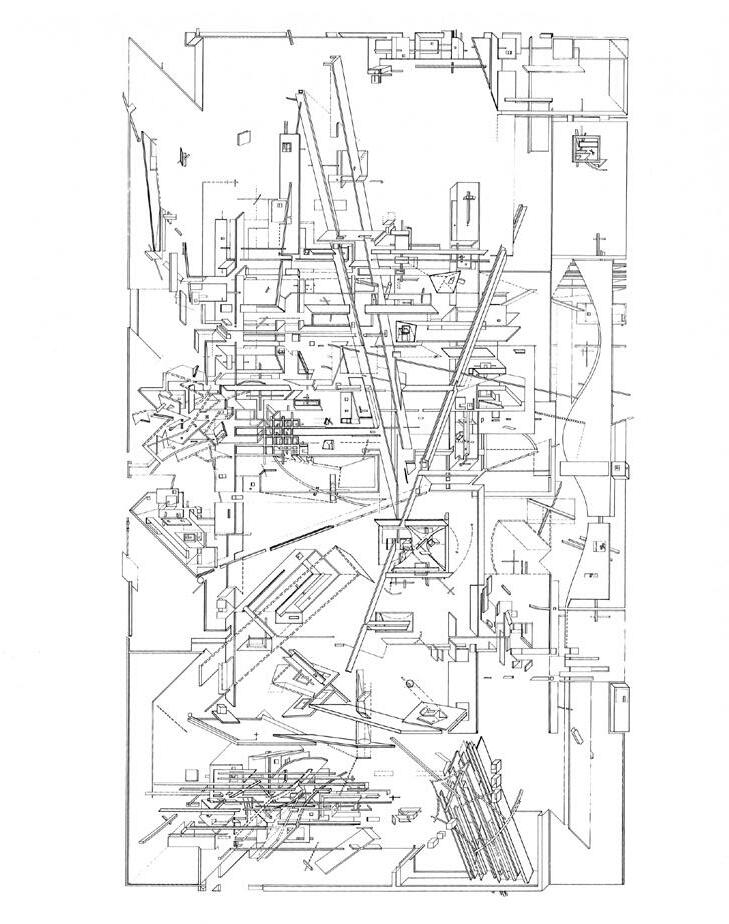
SPACE COMPLEX
Course: Media and Modeling
Instructor: Harris Dimitropoulos
Spring 2020
BASIC IS BASIC LINE DRAWINGPLAN, ELEVATION REBAR REVIVAL PROJECTIVE GEOMETRY 10 11
SURFACE CURVATURE ANALYSIS- A FLYING KITE TRIANGULAR WAVING

A square is deformed into a ripply surface.This dynamic surface resembles a flying kite- the kite flies on a windy day. The colors vary with the degree of curvature, and the highest degree of curvature on the kite is colored in blue.
MATHEMATIC FORMS I
Course: Media and Modeling II
Instructor: James Park
Spring 2020
In contrast to the soft surface of the kite, a sharp hollow pentagonal ring is morphed into the surface. By virtue of the wavy surface, the shape of the pentagon becomes dutile.The blue and orange seggregate the surface into a “hot zone” and a “cold zone”.
In contrast to the soft surface of the kite, a sharp hollow triangular ring is morphed into the surface. By virtue of the wavy surface, the shape of the triangle becomes dutile.The color gradient from orange to yellow is harmoniously displayed on the structure.
Calla Lily symbolizes magnificant beauty. It is exquisite: even when it is full-blown, its outer petal strives upward.
Construct Point
X: ((a*cos(u))*sin(v))
Y: ((a*sin(u))*sin(v))
Z: (a*(cos(v)+log(tan((0.5*v)))))+(b*u)
This is a Turbo blade spinning in a fluctuating motion. The motion trail of the sharp rim creates a drapery pattern.

Construct Point
X: v*cos(u)
Y: v*sin(u)
Z: a*cos(b*u-v)
Nature produces elegant and organic geometry. A small creature has a marvelous universe and its center.
Construct Point
X: (1+cos(u/2)*sin(v)-sin(u/2)*sin(2*v))*cos(u)
Y: (1+cos(u/2)*sin(v)- sin(u/2)*sin(2*v))*sin(u)
Z: sin(u/2)*sin(v)+ cos(u/2)*sin(2*v)
MATHEMATIC FORMS II
Course: Media and Modeling II
Instructor: James Park
Spring 2020
CALLA LILY DUCTILE PENTAGON TURBO BLADE IN MOTION MOON SNAIL
PROJECTIVE GEOMETRY PROJECTIVE GEOMETRY 12 13
PARAMETRIC BUILDING SYSTEM

PRADA AOYAMA CASE STUDY
Course: Media and Modeling III
Instructor: James Park
Location: Shanghai, China
Collaborator:
Yining Chen- Elevation Presentation+ Diagrid Analysis
Richard Fridy- Plan Presentation+ Interior Structure

Patricia Rangel- Section Presentation+
Shanghai Jiading Jiaxi Blower Limited Company (Manufacturer)
Spring 2020
This project aims first to explore the animation plugin in grasshopper, then flex an intricate Spatial Instrument in GH, utilizing dynamic analytical approaches for geometric construction and parametric operation. The limit of digital volume is 25m x 25m x 25m. In the volume, develop operable mechanisms that afford numerous modes of a variable input, relational hierarchies, dataflow logic, and behavioral differences. The required operations, approaches, and components are Global Values (Set and Get) and State GateDispatch.

Parametric Design Variation- Prada Tokyo Aoyama
Projection lines traced between the segments described before frame the forms of the vertical chases that extend through the building.
in the facade and the other reaching the middle of the opposite facade.
Chen A SEGMENT
Prada Aoyama Tokyo Herzog de Meuron Structure Analysis
CHASES
Annie
Each facade of the building split into nearly-
VERTICAL
EXTRUDED DIAMONDS
touching
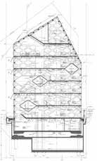
FLOOR PLATES that relate to the edges of the diamond extrusions. 6—B 8—E 4—E 6—F 5—I 3—E 1—G 1—G 2—I 4—11 E 1 F I 10 2 C G J 11 3 6 DD H K 4 7 5 8 1 6 EAST SECTION Scale 1 250 EAST SECTION WEST SECTION When examining the two full oors of the building there 2:5 ratio terms of the diamond height of the 2nd and 5th oor. The light blue shaded area represent the sections of the east-facing wall that contains celiling height two diamonds. As portion of the total area of the wall, the quantity oor space that contains two diamond height ceilings approximately 40% or 2:5 ratio. The vertical wall ratios have strong 2: ratio on the section facing east. When the mullions at the ceiling points are extruded down to their opposite wall, clear 2:5 ratio seen on the oor and along the northern and southern walls the structure. The pattern the cantilvered oors from vertical perspective goes 2-4-2-4 in terms of diamond height dimension. In terms horizontal diamond length against the eartern wall the sequence follows 3-5-3-3 pattern. With the nal length falling across span of six diamonds as opposed seven in the rst three cantilevered oors. As seen by these diagrams of the east and west elevation and sections, in the entirety of the building, only the second oor able maximizes the entire surface area of the building’s footprint. The fourth oor because of the third tunnel cantilevered on the east wall, though appears complete on the west wall. The fth oor, although not cantilevered, takes up smaller footprint due to the angle the roof. Therefore the 2:5 ratio exhibits itself once again by by establishing center of stability on the second seven levels. FULL FLOOR WALL AREA Ratios Unit of Measurement CANTILEVERED FLOORS Ratios VERTICAL WALL Ratios (2) 4H 4H (2) 5H 7L 2L 3L (5) 10H (5) 10H 2H W H=2750 mm L=3200 mm Wall with 2 Diamond Height 40% 7L 5L
side
seam
14 15
- The centroid of Tunnel 1 is at the oor height 2H; the centroid of Tunnel 2 at the oor height 6H; the centroid of Tunnel 3 is at the oor height 8H. The distance ratio between the ground level and the centroid of these three tunnels are 2: 4: 2.
- Both Tunnel 1 and 2 begin from SPREAD 1 and ends at SPREAD 3, and both the distance from the beginning centroid to the end centroid of these two tunnels are 8L.
- Tunnel 3, unlike Tunnel 1 or 2, starts from SPREAD 1 and ends at Spread 5 which is adjacent to Spead 1 on the building, on the spread the distance from the beginning centroid to the end of the centroid is 17 L.
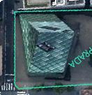
- According to the SPREAD, Each tunnel has a point hitting a corner of the building, Tunnel 1 hits the corner of the North and West facade (SPREAD 2&3), Tunnel hits the corner of the East and North facade (SPREAD 1&2), Tunnel 3 hits the South-West and South facade (SPREAD 4&5).


- From the observation of the glass types on the surface where all tunnels begin and end, most of the glasses are buble glass (to outside), therefore the visitors who traverse through the tunnel could see the outside world.
- Most glass panels on SPREAD 5 and partial glass panels on SPREAD 1 are smoky glasses, those are the facades for where the staircases locate inside the building.

seen by these diagrams of the east and west elevation and sections, in the entirety of the building, only the second oor able maximizes the entire surface area the building’s footprint. The fourth oor because the third tunnel cantilevered on the east wall, though appears complete on the west wall. The fth oor, although not cantilevered, takes up smaller footprint due to the angle of the roof. Therefore the 2:5 ratio exhibits itself once again by establishing center of stability on the second of seven levels.
- Most of the openable glasses are on SPREAD 1, 2 and 3. The ones on the vertical walls are re escapes. All the re escapes locate on the oors with height of 4H, 6H, 8H and 10H, the distance ratio between these oors are 2: 2: 2.

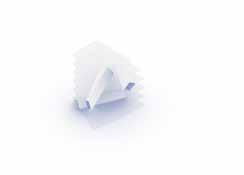
of the massing the roof line that connects all the vertex heights to one of its two ends.

Inputs: —Diagrid Lines —Edges of Vertical Chases or alignment)
Parametric
Overview:
This system, still in progress, creates horizontal tunnels that function similarly to the vertical chases.
Instead of referencing the structural diagrid nodes and producing extrudable shapes through projection lines, the tunnels are extruded from the steel diagrid itself. Tunnels are varied by assigning differing start and end panels. Floor slabs are, in turn, trimmed by the intersections produced by these tunnels.
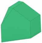
Input: Unfolded elevation with folding edges







Input
Step 1: Make the the first triangular set of points, set the gap length on the horizontal axis as 3200mm, and the gap length on the vertical axis as 2750mm. The number of horizontal intervals is 23, the number of vertical in-tervals 9.

is 9.
Step 2: Create the second set of points as Step 1. Move them 1600mm to the right, then 1375mm up.
Step 2: Create the second set of points as Step 1. Move them 1600mm to the right, then 1375mm up.
Step 3: Connect the first set of points with the second in an one-to-two relationship.
Step 4: Connect the second set of points with the first in an one-to-two relationship.
Step 5: Turn off the points and get only the diagrids.
Step 3: Connect the first set of points with the second in an one-totwo relationship, Step 4: Connect the second set of points with the first in an one-totwo relationship, Step 5: Turn off the points and get only the diagrids.
Variation: Roof Collage
Final Step: Project the diagrids onto the building.
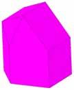
All diagrids are in rhombic shape which has the identical length of side. One diagrid, as module, determines the massing of the building in terms of the amount and size of it. The ratio of the shorter diagonal length of one rhombus to the longer diagonal lenght is always 2: 3.2. In the manner of the generative process illustrated above, the diagrds could keep expanding horizontally/ vertically to fit variety of massing (the prerequisite is that the massing changes in the unit of modules.) In all design variations, the diagrids expand in the horizontal direction in response to the length of the Nothern and Western Walls.
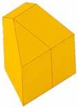


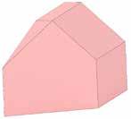
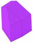
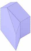
All diagrids are in rhombic shape which has the identical length of side. One diagrid, as module, determines the massing of the building in terms of the amount and size of it. The ratio of the shorter diagonal length of one rhombus to the longer diagonal lenght always 2: 3.2. In the manner of the generative process illustrated above, the diagrds could keep expanding horizontally/ vertically to fit variety of massing (the prerequisite is that the massing changes in the unit of modules.) In all design variations, the diagrids expand in the horizontal direction in response to the length of the Nothern and Western Walls.
3L L=3200mm H=2000mm DIMENSION ANALYSIS ON FACADES AND FLOOR HEIGHTS 1:400 12H Tunnel Tunnel Tunnel 2H 6H 8H 10H 1:400 GEOMETRY ANALYSIS 1:1000 ELEVATION SPREAD EAST NORTH WEST SOUTH WEST SOUTH 2H 4H 6H 8H 10H 1:400 GLASS TYPE ANALYSIS FLAT GLASS SMOKY GLASS SMOKY GLASS (OPENABLE) BUBLE GLASS (TO INSIDE) BUBLE GLASS (TO OUTSIDE) SMOKY BUBLE GLASS (TO OUTSIDE) >> escapes/ outlet air opening recooling >> About of the cladding >> About of the cladding >> most them are distributed on facades next other buildings (maintaining privacy) >> Only ground oor (shopping windows) FLAT GLASS (OPENABLE)
LENGTH HEIGHT HEIGHT
SPREAD SPREAD 3% 3% <1% 11% 9% 2% <1% <1% This diagram estimates the proportion of each type of geometry on extorior wall of the building. Most of the glass panels are rhombic, on the edge of each spread, the rhombics are cut into di erent shapes triangles. The base of the massing the oor plan of this building. And the oor plan strategically begins with dot on the ground that sits in the corner of an alley and sidewalk in Tokyo, Japan. From that point, architects Herzog de Meuron make deliberate Variation + rhomboid length MASSING OF VERTICAL CHASES IN CONSTRUCTED BUILDING SECTION DETAIL OF DIAGRID PANEL, SHOWING THICKNESS THAT HIDES STANDARD W-FLANGE EXO-STRUCTURE. MASSING VARIATION THAT SPREADS CHASES MORE EVENLY THROUGH THE FLOOR PLATE MASSING VARIATION THAT AIMS TO PRODUCE INSIDE CORNERS, STILL ONLY USING THE SAME PARAMETRIC LOGIC. Variation + rhomboid length CRITICAL AXES BASE SHAPES FILLET EDGES AXIS VARIATIONS HORIZONTAL TUNNELS
ORIGINAL SLABS SLAB VAR. Design Variations — Rich Fridy Design Variations Variation 4+7 rhomboid lengths NW Walls Variation 3: 7+4 rhomboid lengths NW Walls Variation 9+3 rhomboid lengths NW Walls Variation 5: 5+3 rhomboid lengths NW Walls Variation 1: 6+11 rhomboid lengths NW Walls
DIAGRID Points Lines Diagrids
SECONDARY SYSTEM-
EAST SECTION Scale 1 250 EAST SECTION WEST SECTION When examining the two full oors the building there 2:5 ratio terms the diamond height the 2nd and 5th oor. The light blue shaded area represent the sections the east-facing wall that contains ceiling height two diamonds. As portion the total area the wall, the quantity of oor space that contains two diamond height ceilings approximately 40% or 2:5 ratio. The vertical wall ratios have strong ratio on the section facing east. When the mullions the ceiling points are extruded down to their opposite wall, clear 2:5 ratio seen on the oor and along the northern and southern walls the structure. The pattern the cantilevered oors from vertical perspective goes 2-4-2-4 terms of diamond height dimension. In terms of horizontal diamond length against the eastern wall the sequence follows 3-5-3-3 pattern. With the nal length falling across span six diamonds opposed seven in the rst three cantilevered oors.
FULL FLOOR WALL AREA Ratios Unit of Measurement CANTILEVERED FLOORS Ratios VERTICAL WALL Ratios (2) 4H 4H (2) 5H 5L 2L 5L 3L 3L 3L 10H 10H 2H E W H=2000 mm L=3200 mm Wall with Diamond Height 40% 7L 98° 6 + 11 rhomboid lengths variable walls + rhomboid lengths variable walls + rhomboid lengths variable walls 4 + 7 rhomboid lengths variable walls + rhomboid lengths variable walls + rhomboid lengths variable walls 5 + rhomboid lengths variable walls 9 + 6 rhomboid lengths variable walls + rhomboid lengths variable walls 3 4 5 6 7 8 9 10 11 WALL (PLAN- NE) WALL LENGTHS RHOMBOID MODULES 3 45 67 8 9 onnect the vertices the intersection these two circles closest to plan-E. The lines connecting these points will form the nal two walls the building, Connecting all the lines will create the oor plan of the Prada Ayoama building Tokyo, Japan. Draw a line that is seven rhomboid lengths plan-north and reorient to be 98 degrees from original line.
zero degrees, four rhomboid lengths along the site boundary at plan-S. Begin with dot at the plan-SW. The base of the massing the oor plan of this building. And the oor plan strategically begins with dot on the ground that sits in the corner of an alley and sidewalk in Tokyo, Japan. From that point, architects Herzog de Meuron make deliberate move that slightly shifts two equal-distant parallel lines. The vertex of those lines then determine the length and angle of the corresponding walls that became the main entrance and plaza the Prada Aoyama building. The second most important piece
7L L=3200mm H=2000mm DIMENSION ANALYSIS ON FACADES AND FLOOR HEIGHTS 1:400 12H Tunnel Tunnel Tunnel 10H 1:400 GEOMETRY ANALYSIS 1:1000 ELEVATION SPREAD EAST NORTH WEST SOUTH WEST SOUTH 2H 10H 1:400 GLASS TYPE ANALYSIS FLAT GLASS SMOKY GLASS SMOKY GLASS (OPENABLE) BUBLE GLASS (TO INSIDE) BUBLE GLASS (TO OUTSIDE) SMOKY BUBLE GLASS (TO OUTSIDE) >> escapes/ outlet air opening recooling >> About 20 % the cladding >> About % the cladding >> most them are distributed on facades next to other buildings (maintaining privacy) >> Only ground oor (shopping windows) FLAT GLASS (OPENABLE) - The centroid of Tunnel the oor height 2H; the centroid of Tunnel the oor height 6H; the centroid Tunnel the oor height 8H. The distance ratio between the ound lev and the centroid of these three tunnels are 2. -Both Tunnel and begin from SPREAD and ends SPREAD 3, and both the distance from the beginning centroid to the end centroid of these two tunnels are 8L. - Tunnel unlike Tunnel 1 or 2, starts from SPREAD 1 and ends at Spread 5 which adjacent Spead 1 on the building, on the spread the distance from the beginning centroid to the end of the entroid is 17 L. -According the SPREAD, Each tunnel has point hitting corner the building, Tunnel hits the corner the North and West facade (SPREAD 2&3), Tunnel hits the corner of the East and Nor facade (SPREAD 1&2), Tunnel hits the South-West and South facade (SPREAD 4&5). LENGTH HEIGHT HEIGHT -From the observation of the glass types on the surface where tunnels begin and end, most the glasses are buble glass outside), therefore the visitors who traverse through the tunnel could see the outside world. -Most glass panels on SPREAD and partial glass panels on SPREAD are smoky glasses, those are the facades for where the staircases loca inside the building. -Most of the openable glasses are on SPREAD 1, and The ones on the vertical walls are escapes. All the re escapes locat on the oors with heigh of 4H, 6H, 8H and 10H, the distance ratio between these oors are 2. - This diamond shape occurs most equently and all them ar on the vertical alls. - These two strands iangles re ec on each other - This diamond shape occurs second frequently and all of them on facade of hombic roof. - This diamond shape occurs third frequently and all them are on facade rhombic roof. - This diamond shape occurs second frequently and all of them ar on facade of hombic roof. SPREAD SPREAD 58% 11% 3% 3% <1% 11% 9% 2% <1% <1% This diagram estimates the proportion of each type of geometry on extorior wall of the building. Most of the glass panels are rhombic, on the edge of each spread, the rhombics are cut into di erent shapes of triangles. Design Variations Variation 2: 4+7 rhomboid lengths NW Walls Variation 7+4 rhomboid lengths NW Walls Variation 4: 9+3 rhomboid lengths NW Walls Variation 5: 5+3 rhomboid lengths NW Walls Variation 1: 6+11 rhomboid lengths NW Walls Final Step: Project the diagrids onto the building. SECONDARY SYSTEM- DIAGRID Points Lines Diagrids Input Input: Unfolded elevation with folding edges. Step 1: Make the the first triangular set of points, set the gap length on the horizontal axis as 3200mm, and the gap length on the vertical axis as 2750mm. The number of horizontal intervals 23, the number of vertical intervals
Procedure by drawing line at
Diagrids- Annie Chen Diagrids- Annie Chen
Massing- Patricia Rangel
Plan Rich Fridy 16 17
Section- Patricia Rangel
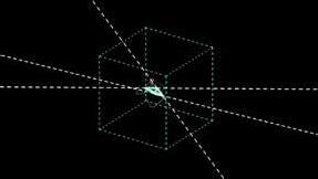
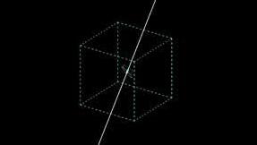
SPATIAL INSTRUMENT GRASSHOPPER ANIMATION







Course: Media and Modeling III
Instructor: Keith Kaseman
Location: Shanghai, China Spring 2020
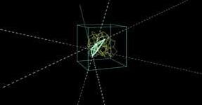
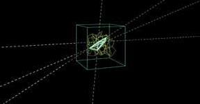
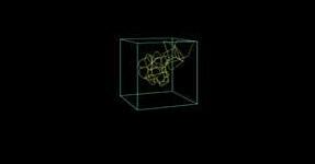
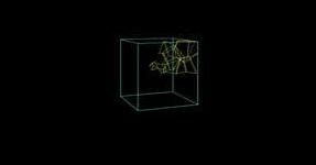
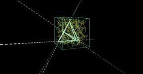
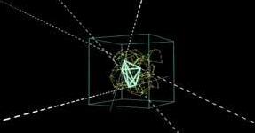
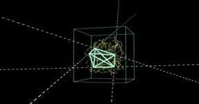
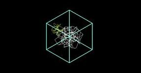
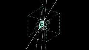
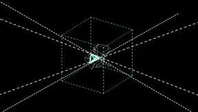
This project aims first to explore the animation plugin in grasshopper, then flex an intricate Spatial Instrument in GH, utilizing dynamic analytical approaches for geometric construction and parametric operation. The limit of digital volume is 25m x 25m x 25m. In the volume, develop operable mechanisms that afford numerous modes of a variable input, relational hierarchies, dataflow logic, and behavioral differences. The required operations, approaches, and components are Global Values (Set and Get) and State GateDispatch.


SPATIAL INSTRUMENT 18 19 FILM A ROTATING CUBE
GROWTH KNIT VORONOI A BATTLE FILM B FILM C FILM D
DIAGNOL
TEST ANIMATION BREATHING MESH
Course: Media and Modeling III
Instructor: Keith Kaseman
Collaborator: Jiayong Lu, Botao Li, Yining Chen (Form Design)


Location: Georgia Institute of Technology
Spring 2020
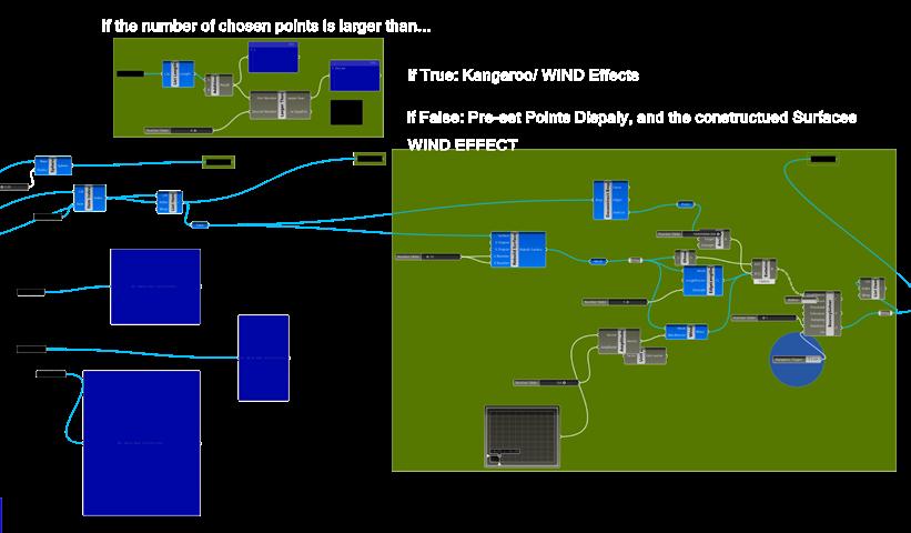
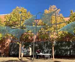
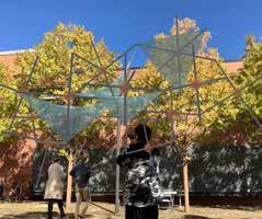
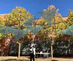
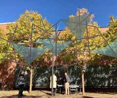
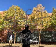
This project tasks to develop, demonstrate, and document an interactive spatial system in real space and at full scale within the volume defined by the Hinman Courtyard. Utilizing Fologram for phones, the collaborative operability of the system uses three synced parameters (live on phones) along with device tracking on more than one phone. The operable spatial systems are free-floating architectural frameworks – spaceframes and canopy structures.




1 6 7 8 9 10 2 3 4 5
MONTAGES
The following constraints and techniques are to be employed:
• Primary curves to be 1 degree; fillets and controlled blend curves
• Global Variables, Stream Gates, State Gates, and Stream Filter operations

WIND PAVILLION OPERATIONAL SPATIAL SYSTEM WIND PAVILLION 20 21
• All geometry visible within Fologram on phones for a live demonstration to be synced grasshopper objects (no visible Rhino geometry!), and a reset button
DRAGONBOT
CREATE “MICROCLIMATE” ABOVE THE COURTYARDE
Course: Media and Modeling III
Instructor: Keith Kaseman, William S. Reynolds
Location: 723 CherrySt NW, Atlanta, GA
Team: Yining Chen, Patricia Rangel, Shrutam Prabhu
Responsibility: Wings Design
Fall 2021
The Hinman Research Building of Georgia Institute of Technology was originally designed as a research facility in 1939. It was later adapted to include graduate-level architecture studios, computer labs, and interdisciplinary research labs.
As the former dean of the College of Architecture, Alan Balfour said, “Hinman is the perfect union of the past, present, and future of architectural research and education at Georgia Tech.” The building carries all the talents and witnesses the birth of great inspirations and works. The back courtyard of the Hinman Building is a crucial area for the students to socialize, repose, and refresh.
The Dragonbot aims to create a recreational space for the users and visitors of the Hinman Building. The inspiration comes from the shape and movements of dragonfly wings. The hightech metallic giant installation consists of a prime arm carrying tiny wings fluttering in the air. With the fluttering wings, the Dragonbot creates a breeze and shades above the courtyard during mid-summer time. The designers envision further tech development on the wings to provide heat during winter.

GRASSHOPPER DEFINITION- PRIMARY MEMBER BEAM ROTATION


Set the point on the lower Hinge Joint as the Centroid and set the Amplitude/ Rotation angles of the Primary Member


Deconstruct the rotated Primary Members, and list out all the vertices. Move the vertices in a fixed amplitude to confirm the thickness of each member


Make surfaces of the Primary Member out of all the edges. The volume of the rotated Primary Member is later synced with Fologram

GRASSHOPPER DEFINITION- FLUTTERING SEQUENCE SETTING


The flutter movement is controlled by several variants including Unit Vector (Direction), Fluttering Domain (the range of movement), Fluttering/ Rotation Pattern (in the designed script, the mathematic expression is fixed as sine), and Shift Sequence
The way of fluttering on both sides of the wing is identical
INSTALLATION
& MOVE SEQUENCE
PEDESTALS- CONCRETE 2 8 9 3 4 10 11 12 5 6
WINGS
HINGE JOINTS
PRIMARY
FLUTTERSHIFT SEQUENCE NO. 06
SUPPORTS
PRIMARY MEMBER- BEAM
SURFACE CURVES
JUNCTION SUPPORT
FLUTTERSHIFT SEQUENCE NO. 12
TENSION CABLES
FLUTTERSHIFT SEQUENCE NO. 0
FLUTTERINGSHIFT SEQUENCE NO. 18
DRAGONBOT
Connect all the vertices and create the edges of the rotated Primary Member 22 23
FORM INTERVENTION

Matt Anderson, Director of Communications at Olson Kundig Architects, said, “Ultimately, truly timeless architecture is inseparable from the place; its authenticity derives from its context, allowing it to remain relevant.”

Though highly technical and futuristic, this project intends to reflect a growing desire for more subtle, harmonious interventions with surrounding hardscapes.
The shiny metallic color, the subtleness of mechanical details, and the unique shape of the machine make it a landmark near the Hinman building. As water waves under the impact of the wind, it is constantly dancing with the branches and leaves of the cinnamon trees. From the observation above the courtyard, the curvature of the Dragonbot resonates with the surrounding cinnamon trees. The edge of the Dragonbot maintains its organic form, and the space segregated by the installation and circulation also mimics the shape of the surrounding nature.
ELEVATION: PRIMARY MEMBER BEAM ROTATION 10ft 10ft DRAGONBOT DRAGONBOT 24 25
0 15° 30°
BUZZ STATION
BUS STOP ON GEORGIA TECH CAMPUS
Course: Construction Technology I
Instructor: Charles Rudolph
Fall 2020
INITIAL IDEA
The project aims to provide shelter, seating, and social distancing (to prevent COVID-19) for waiting for passengers on the campus of Georgia Tech. BUZZ, the school mascot, inspires the shape of a beehive/ hexagon. The hexagon develops into an octahedral space and other three-dimensional spaces which connect to it on edge. Each room is segregated from one another.


BUZZ STATION 26 27


28 29


30 31


32 33


34 35


36 37


38 39


40 41


42 43


44 45


46 47


48 49


50 51


52 53


54 55


56 57


58 59


60 61


62 63


64 65


66 67


68 69


70 71


72 73


74 75


76 77
BASIC IDEA- BOOT ROTATION
The boot rotation is the primary motif and key to initiating the design. In other words, this gesture highlights the central axis— the inclination of the structure. During the design progress, the designers put on the holo lenses, rotated the boots, and synchronized the rotation on the laptop. Afterward, the boots are fixed at an angle, and designers can explore different connections between the nodes.
EXPERIENTIAL INTIMACY
A PLAY WITH VR BY HOLOLENS
SIMULTANEOUS MANUFACTURE
Course: Advanced Production
Instructor: Keith Kaseman, William S. Reynolds
Location: 723 CherrySt NW, Atlanta, GA
Team: Yining Chen, Moath Rabahbah, Jiayong Lu, Sophie Myers, Bhoomika Taneja
Responsibility: Hololens Design Progress+ Manufacture
Spring 2022
DESIGN PROCESS- DIGITAL FABRICATION


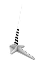


The project aims to integrate various design tools, including laptops, holo lenses, and boots. These three main incentives determine the configuration of the project. The design process demands several team members operate simultaneously. The holo lenses need to be connected to the grasshopper script on the laptop and the QR Code from the boots, so they can accurately capture the hand gestures and locate the two structures and the nodes on them to initiate the design process.

HINMAN GATE- SUMMER


The silver rebar gate sits sturdily in the courtyard, with the breeze dabbing and birds chirping. The summer is hot, and the coldness of the color on the rebars and the holographic plastic sheets cools down the fever. The sheets are iridescent: they shine brightly, as the green cinnamon leaves shine under the sun. Everything is in crazy colors— the trees, the gate, the shadows, like a midsummer fantasy in the backyard.

MANUFACTURE PROCESSREBARS CUTTING AND WELDING
EXPERIENTIAL INTIMACY 79 78
The rapid advancement of urbanization and the dramatic rise of the urban population lead to a drastic increment in the output of municipal solid waste. The nation’s waste has exceeded 250 million tons, with an average annual compound growth rate of 2.1%. Therefore, the government tends to treat this garbage quickly and effectively to prevent the garbage siege phenomenon and severe air, water, and soil pollution.
As an industry representative, Liming Resources dedicates to reusing all accessible sources to protect the urban environment. Liming Resources officially launched the research on waste and nutrients in July 2019. Based on the systematic analysis of the nutrient composition, the researchers analyzed pollution characteristics of the biogas residue from the anaerobic fermentation of food waste in the region and the ability of partial biogas residue to be carbonized and used as a biochar base fertilizer. The agricultural safety of biogas residue and the effect of biochar and carbon-based fertilizer on improving the fertility of farmland soil were studied.
This collaborative project with Shanghai Liming Resources Recovery Co. Ltd focuses on recycling methods of constructive and domestic waste in Shanghai. Eventually, with the research data and documentaries of the research process, these dumped materials are reformed and reconstructed into an interesting, monumental, and natural lab for future experimentation on reproducing fertilizers from the residue of incinerated domestic waste.
REBAR REVIVAL

TRASH TO TREASURE
Course: Material Diversion

Instructor: Debora Mesa Molina
Location: Shanghai, China
Collaborator: Shanghai Liming Resources Reuse Co., Ltd. (Client)
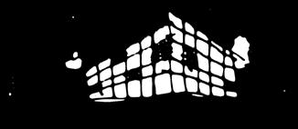
Shanghai Jiading Jiaxi Blower Limited Company (Manufacturer)
Spring 2021
Due to an increment in urban reconstruction, the city will abandon more wasted constructive materials like rebars. The large-scale sculptural piece could be constructed on a riverbank or coast to celebrate the re-bloom of the material in our daily life. LED light tubes are attached to the framing. The recovered rebars accompany the city’s revival- both old and new materials are included and utilized. When night comes, the city is still wide awake. The lights on the rebar monument and the city lights twinkle in the darkness. With great lighting, the monument functions as a lighthouse gallery introducing the magic of recycling to the citizens. The lights are on from early morning to late night. The celebration of the old material on the water in the city is always on.


REBAR REVIVAL 81 80
INTRODUCTION MATERIAL REUSING AND DESIGN IN THE FUTURE
XL PERGOLA H.A.B.O.R. IN THE FUTURE
Field Trip and Material Hunting
This project involves field trips, resource gathering and selection, and industry collaboration. Visiting the Resource Company to browse the recycling progress and products could inspire the use of material, and understanding the industry’s ultimate goal could promote an ideal project built for this environmentally friendly space. The final selected material is a colossal rebar piece disassembled from a vast machine- it primarily functioned as a filter that sorts the waste.
Material Gathering and Transportation Oxyacetylene Rebar Cutting on Site
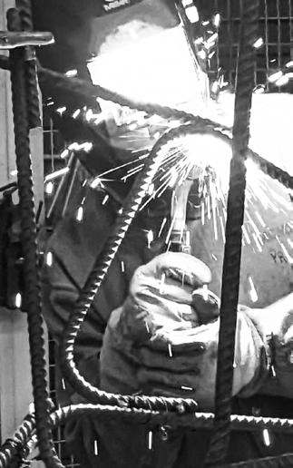
After several design experimentations, including sketching and modeling, the pieces are cut into designated sizes on-site for the intended design and more accessible transportation. Two process gasses, Oxygen (O2) and Acetylene (C2H2), were mixed in the oxygen-acetylene torch. Separate compressed gas cylinders stored both gases. The gases were mixed at the correct proportions and ignited. Gas valves on the torch were adjusted precisely to the volume flow of the gasses. With the help of an additional oxygen blast trigger, the nozzle released extra oxygen. The supplemental O2 reacted with the metal to produce iron oxide and process heat, which is essential for the cutting process.
Shapes+ Body Exploration

This process tests a series of explorations of the shape and accessibility of furniture. Use sizes to categorize the sitting prototypes: Small, Medium, Large, and Extra Large. After a bunch of installation and testing with the body, decide on prototypes to use in the final design.


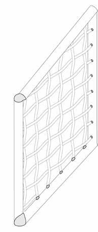


Framing + Facializing
Installation- Wielding
On-site Installation

A. Progress of Rebar Meshes Welding to the Rebar Frame (Electrowelding)
Lay the piece flatly on the ground due to safety concerns. The progress produces many sparks and flames, so gloves and goggles are required.
B. Steel Slots Welding & Installation of Acrylic Panels (Gas Shielded Welding) Mosiac the acrylic panels to the welded frames while the piece stands straight up. Use a ladder during the installation of the components at higher levels.

After the pergola is complete, it is transported back to the Liming Resources as an educational, artistic piece. This project’s construction could happen in different places. Designers could transform it into a public gallery in the city center or make it into a monumental structure in the suburban area, an evidence representing human intrusion into nature in this prosperous industrialized era.

C2H2 biomass O2 DISCOVERY TO PRACTICE
Use the rebar to construct the framing of the pergola.
Cut the rebar meshes to fit in the frames.
Weld all the rebars into the standing pergola.
REBAR REVIVAL REBAR REVIVAL 82 83
Install the acrylic pieces to the frame.
KITCHEN SAFETY FOR OLDER ADULTS
INTRODUCTION
WHY SHOULD WE CARE ABOUT KITCHEN DESIGN FOR THE ELDERS
The level of functional independence is determined by the level of functional limitation, which means the restrictions on basic mental and physical actions (Stuck et al., 1999, p. 445-446). According to Figure 1, the functional capacity starts to decrease from adult life to older age. Therefore is important to consider levels of functional independence- whether the client lives with a wheelchair or caregiver- when designers are designing for different clients, especially for the elders. Some physical illness and mental discoordination have impeded he elderly from fully interacting with their environment because they lose functional independence. For example, the common disease osteoarthritis causes stiffness and decreases the older ’s range of motion, and some of them will have difficulties walking or even standing (Stuck et al., 1999, p. 445-446); cognition impairment like dementia could cause difficulties reading, understanding, or expressing. With the malfunctioning body the interaction with the surroundings will be challenging (Parke et al., 2013, p. 1206). Additionally, other major risk factors like falling could exasperate the functional status decline, and community-living persons who are 65 years or older have experienced at least one fall annually (Fahlström et al., 2018, p. 575). may seem surprising that so many people fall in their own kitchen, yet some of the seemingly most innocent rooms in the home can actually be he most dangerous (Parnes, F 2009, p.01 In this poster, the research tends to reduce the risk of falling and maintain independence for the elders in the kitchen design.

METHODOLOGY
The poster integrates study that intends to examine different parts in the kitchen that could cause the accident of falling, starting by observing the journey map of an elder’s one day in the kitchen. According to the journey map, plan mind map is drawn in order to analyze and collect design problems in the kitchen. From the plan mind map, set of elements are highlighted, including the layout, flooring, grab bars and lighting according to the collected information. Next in the design opportunities, each of the highlights will be parrelly layed out and discussed with more etailed researched information and design variations. At last, system map will conclude the work flow of design for the kitchen regarding different levels of functional independence.
FLOW CHART
JOURNEY MAP + PLAN MIND MAP

GRANDMOTHER’S ONE DAY IN HER APARTMENT
DESIGN OPPORTUNITY
1. GENERAL KITCHEN LAYOUT COMPARISON STOVE+ FRIDGE+ SINK+ (DINING)
kitchen’s layout and design plays a crucial role its function and safety. The useful design suggestion related to risk of falling are:
Stoves should be installed where they won’t present a work-flow or traffic hazard. placed too close to doorway anyone entering the kitchen may accidentally knock pot off the stove, brush their skin against the heated metal, or even catch their sleeve on fire.
- The refrigerator and stove should be kept far enough from one another that anyone transferring hot things from the oven will not run into someone else who is getting food from the refrigerator
(Kitchen Safety at the Center Kitchen Design, 2022, online From the observation of the popular kitchen plan, most of the ayouts are not friendly enough for the wheelchair because challenging make lots of turns in a confined space. According to the circulation presented, is hypothesized that the single wall and L-shaped kitchen could be the most friendly layout for users with wheelchairs.
SYSTEM MAP
2. DIFFERENT KINDS OF GRAB BARS
Grab bars could significantly reduce the risk of falling (Burfield, 2019, online). From the collected information about grab bars, the suction grab bar is least friendly to the uses due to its instability.

These grab bars are installed securely to the wall with mounting screws and anchors (Hall, 2022, online).
3. INCREASE LIGHTING

- Lighting a kitchen layers eliminates shadows and helps ensure safe work surface. The key to lighting in layers is to install light fixtures in a variety of places, including the ceilings, under cabinets, inside cabinets, over kitchen islands and in the form of pendant lighting.
- Install Different Types of Lighting. Installing different types of lighting is another way to light in layers. Different types light fixtures point light different directions, which ultimately helps ensure kitchen surfaces are properly lit.
- Make the Most of Natural Lighting. Multiple windows, skylight and large windows in the kitchen will maximize natural light. And most of the kitchen lighting should be pendant lighting.
Additionally, eco-friendly and efficient to use dimmable CFLs and LEDs. (Kitchen Safety at the Center Kitchen Design, 2022, online

DESIGN OPPORTUNITY
One of the most common injuries in the kitchen caused by slipping and falling. When people are cooking with slippery substances like oils and water, it’s inevitable that some of them will get on the floor. Slip resistance is vital because grease, spills and even wet food can cause nasty fall. Therefore, installing non-slip flooring the kitchen is recommended.
Some good slip-resistant flooring choices are laminate, textured tile and soft-glazed ceramic tile. Some types of synthetic material, cork, vinyl planks and laminate are all nonslip. The floor should support promote the ease of trave-the right flooring allows clients to move quickly, even they are using wheelchair, walker or cane. If the kitchen has tile flooring, a throw rug with non-skid backing good idea, especially around areas that get wet often.
(Kitchen Safety the Center of Kitchen Design, 2022, online

Other Factors to Consider
Adjustable clamps fit the grab bar base tightly over the rim of the bathtub, providing stability when getting in and out of the tub (Hall, 2022, online).
Affordability: the choosen material should fit the budget without compromising on quality and durability.
Maintenance: elder people do not want to spend too much time on cleaning. Try to find flooring material that’s easy to clean and doesn’t require regular treatment to maintain it.
Comfort: Softer flooring puts less pressure on users’ joints, so they won’t have as much pain as they walk. Avoid materials that retain heat or cold because they could be uncomfortable for users’ feet.
Health concerns: users have allergies or other respiratory conditions, the dust and allergens in the air can trigger symptoms. Consider the best flooring to prevent allergies so their house can be safe and comfortable.
(Best Flooring for Older Adults, 2022, online)
Course: Health Care Design of the Future
Instructor: Yousef Bushehri
Fall 2022
These grab bars attach to the wall with suction cups and are best used as temporary measure, such as when traveling or while recovering from certain surgeries or injuries. Suction grab bars are generally used to assist with balance and not intended support your full body weight. These bars should only be installed on nonporous surface, such as tile—never on drywall (Hall, 2022, online).
These grab bars fold-down or flip-up when not in use save space in tight areas, such as beside the toilet or sink (Hall, 2022, online).
Free-standing grab bars are often floorto-ceiling tension bars located beside the tub or shower to assist with exiting and entering. Another type is a toilet enclosure with stand-alone rails and a safety base to help with sitting down and standing up (Hall, 2022, online).
Figure 3. Grab Bars. Retrieved October 20, 2022, https://www.forbes. com/health/healthy-aging/best-grab-bars/
CONCLUSION
According to the journey map, the elders could spend a lot of ime in kitchen in their every-day life, and according to all the collected information, kitchen is a room where contains lots of safety threats that could cause elders to fall when they are spending their time in there. Therefore it is important for designers to be aware of these latent threats and reduce the risk of falling in the kitchen. In order to achieve this goal the designer could improve the general kitchen layout, add grab bars to necessary places in the kitchen, increase lighting in the kitchen, and choose non-slippery flooring. By the observation of different layouts, the single wall and L shaped layout could be most the friendly for the wheelchair users. All the grab bars expect for suction bar are efficient to reduce the risk of falling. From researching about types of fixtures, there are five different types of lights that could be combined to increase lighting. At last, the material of flooring in the kitchen should be abrasive enough to prevent falling. With all the information a system map is designed, the stronger the functional independence, the wider range of propriate design options are given to the designer According to different independence situations, different design elements are chosen from the list. And there could be further study about the accessibility to different devices and different appliance dimensions for different levels of independence.
6:00 A.M. 7:00 A.M. 8:00 A.M. 9:00 A.M. 10:00 A.M. 11:00 A.M. 12:00 P.M. 1:00 P.M. 2:00 P.M. 3:00 P.M. 4:00 P.M. 5:00 P.M. 6:00 P.M. 7:00 P.M. 8:00 P.M. 9:00 P.M. WAKE UP FROM BED + MORNING ABLUTIONS 6:00 6:35 A.M. 6:35 7:45 A.M. 7:45 8:50 A.M. 8:50 9:55 A.M. 9:55 11:05 A.M. 11:05 A.M.- 12:20 P.M. 12:20 1: 20 P.M. 1: 20 2: 35 P.M. 2: 35 4:00 P.M. 4:00 5: 00 P.M. 5: 00 6: 10 P.M. 6: 10 7: 20 P.M. 7: 20 8: 20 P.M. 8: 20 9:00 P.M. BREAKFAST PREPERATION TAKE MEDICINE TIME RANGE SPENT IN KITCHEN FLOOR PLAN OF MY GRANDPARENTS’ APARTMENT WITH TRAVEL ROUTINE RELATED TO KITCHEN LIGHTING CONDITION RUG POSITION FLOOR FINISH RAIL/ HANDLE DESIGN KITCHEN LAYOUT (EFFICIENT WORKFLOW) ONLINE CHAT WITH FAMILY/ FRIEND HOT TEA GROCERY SHOPPING GROCERY MANAGEMENT + LUNCH PREPERATION + TAKE MEDICINE ONLINE CHAT WITH FAMILY/ FRIEND + TAKE MEDICINE ONLINE CHAT WITH FAMILY WATCH TELEVISION BED TIME FLAT CLEANING AFTERNOON TEA WATCH TELEVISION TAKE SHOWER+ NAP DINNER PREPERATION + SOCIAL (NEIGHBOR/ FAMILY) CLEAN UP + TAKE MEDICINE + HOT TEA POTENTIAL PROBLEM EVALUATION REFRIGERATOR KITCHEN DINING TABLE LIVING ROOM BEDROOM BEDROOM BATHROOM CLOSET CLOSET SINK REFRIGERATOR RUG SINK PATH INSIDE OF KITCHEN DINING ROOM TO KITCHEN OTHER ROOMS TO KITCHEN POTENTIAL SLIPPERY SURFACE POTENTIAL FALLING AREA DUE TO LACK OF LIGHTING Slippery surfaces will increase the possibility of falling. (Aging in Place Ideas for Common Areas, 2022) Lacking of grab bars on slippery surface could increase the possibility of falling.(Burfield, 2019) Unsecured rugs could cause tripping or falling. (Aging in Place Ideas for Common Areas, 2022) The layout, especially the placement of stove which affects the work-flow, could increase the possibility of falling.(Kitchen Safety at the Center of Kitchen Design, 2022) Lighting essential for safe environment. Low lighting causes less clear vision, and increase the chance tripping. Adequate fixtures in every room necessary. (Aging in Place Ideas for Common Areas, 2022) 1. GENERAL KITCHEN LAYOUT COMPARISON STOVE+ FRIDGE+ SINK+
kitchen’s layout and design plays a crucial role its function and safety. The useful design suggestion related to risk of falling are: - Stoves should be installed where they won’t present a work-flow or traffic hazard. placed too close to doorway anyone entering the kitchen may accidentally knock pot off the stove, brush their skin against the heated metal, or even catch their sleeve on fire.
(DINING)
2. DIFFERENT KINDS OF GRAB BARS Grab bars could significantly reduce the risk of falling (Burfield, 2019, online). From the collected information about grab bars, the suction grab bar is least friendly to the uses due to its instability. 3.
- Lighting a kitchen layers eliminates shadows and helps ensure safe work surface. The key to lighting in layers is to install light fixtures in a variety of places, including the ceilings, under cabinets, inside cabinets, over kitchen islands and in the form of pendant lighting. - Install Different Types of Lighting. Installing different types of lighting is another way to light in layers. Different types light fixtures point light different directions, which ultimately helps ensure kitchen surfaces are properly lit. - Make the Most of Natural Lighting. Multiple windows, skylight and large windows in the kitchen will maximize natural light. And most of the kitchen lighting should be pendant lighting. Additionally, eco-friendly and efficient to use dimmable CFLs and LEDs.
INCREASE LIGHTING
4. FLOORING
Figure 1. Functional Capacity by Age Retrieved October 20, 2022, https://longevity.stanford.edu/mobility-division/
One of the most common injuries in the kitchen caused by slipping and falling. When people are cooking with slippery substances like oils and water, it’s inevitable that some of them will get on the floor. Slip resistance is vital because grease, spills and even wet food can cause nasty fall. Therefore, installing non-slip flooring the kitchen is recommended. Some good slip-resistant flooring choices are laminate, textured tile and soft-glazed ceramic tile. Some types of synthetic material, cork, vinyl planks and laminate are all nonDESIGN OPPORTUNITIES RESEARCH INTRO TIMELINE (CASE STUDY) PLAN DRAWING (INITIAL INSIGHT) MIND MAP (EVALUATION) connected DESIGN OPPORTUNITIES (DETAILS) SYSTEM MAP (FINAL DESIGN) CONCLUSION (FINAL INSIGHT) parallel These grab bars are installed securely to the wall with mounting screws and anchors (Hall, 2022, online). SINK REFRIGERATOR SINK REFRIGERATOR SINK SINK REFRIGERATOR SINK STOVE SINGLE-WALL KITCHEN GALLERY KITCHEN PENINSULA KITCHEN U-SHAPED KITCHEN ISLAND KITCHEN L-SHAPED KITCHEN PATH INSIDE OF KITCHEN DINING ROOM TO KITCHEN OTHER ROOMS TO KITCHEN POTENTIAL SLIPPERY SURFACE POTENTIAL FALLING AREA DUE TO LACK OF LIGHTING affects the work-flow, could increase the possibility of falling.(Kitchen Safety at the Center of Kitchen Design, 2022)
-
4. FLOORING
Bathtub-mounted
Suction Folding Free-standing
CONCLUSION (FINAL INSIGHT)
Figure 4. Different types of light bulbs and lamps Retrieved October 20, 2022,https://happyhiller.com/blog/indoor-interior-lighting-guide/
Figure 5. Comparision between different lamps Retrieved October 20, 2022,https://happyhiller.com/blog/indoor-interior-lighting-guide/
Figure 5. Comparision between different lamps Retrieved October 20, 2022,https://happyhiller.com/blog/indoor-interior-lighting-guide/
Figure 2. Popular Kitchen Layout Retrieved October 20, 2022, https://redhousecustombuilding.com/kitchen-design-101-part-1-kitchen-layout-design/
ELDERS’ UNIVERSAL KITCHEN RESEARCH KITCHEN SAFETY FOR OLD ADULTS 84 85
CONFINED SPACE X REBELLIOUS MOVEMENT
Georgia Tech with Savannah College of Art and Design
SARAH COLLINS (Instructor)
YUAN TIAN (Fashion Design)


YINING CHEN (Set Design)
PARKER ASEL (Model)
LYCORIS YAN (Photography)
Fall 2022
In the 1948 film Red Shoes, Peggy, the ballerina, is painfully torn between her career and love. The story is a tragedy. The red shoes are a piece of attraction worn by the protagonist, symbolizing feminine ambition. In the old days, women were not allowed to have career desires. Therefore, in Andersen’s fairy tale, the gods punished the heroine by making her lose her feet for wanting the red shoes. This project aims to show a modern, feminine attitude toward the old story. It intends to exhibit the softness and power of females when pursuing dreams and living life, like a ballet dancer dancing to her music and like her toes in ballerinas, shiny and bright outside, pain and persistence inside.

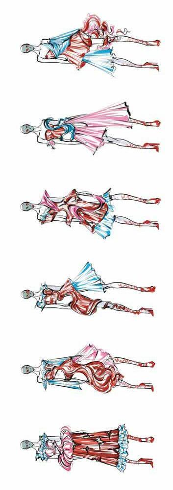
INITIAL CONCEPT | RED SHOES SKETCH OF FASHION DESIGNER AND SET DESGINER

86
Movement Code: PHYSAREALM
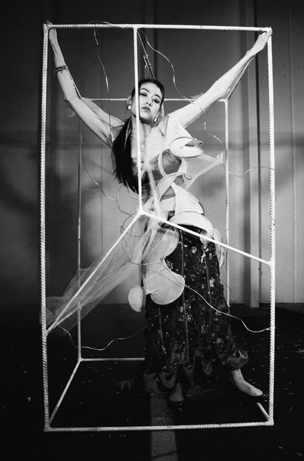
To resonate with the concept of women’s ambition and desire towards their voice and choice in society, along with their gentile yet strong spirit to survive, the condition of the space intends to depict growing and struggling gestures inside of a defined and confined “box. “ The exterior shape conveys minimal space for the development of the body whereas the vigorous geometry, within the strength accumulated inside of the box, suggests a possibility of breaking through the confined shape and growing with freedom.

DANCER #001
DANCER #007
DANCER #002
DANCER #008
DANCER #003
DANCER #009
DANCER #004
DANCER #010

DANCER #005
DANCER #011
is one of the easiest eukaryotic microbes to grow in culture, and it is a model organism for many studies involving amoeboid movement and cell motility. It uses the shortest path to find its food. In grasshopper, the forms of Physarum mimic the dancers’ movements and grow vigorous in the “box.”

Physarum
SPATIAL CONCEPT | WILD GROWTH

DANCER- SPACE INTERACTION
DANCER #006
DANCER #012
Arabesque Soubresaut Temps Levé Glissade Assemble
GT X SCAD
GROWTH + DESIGN VARIATIONS 89 88 GT X SCAD DRAFT
FORM DRIVER | PHYSAREALM WILD
The final set involves a section of the design for model and photo shooting. Both fashion design and set designer determine the selection of units to fit the shooting scene and final looks better.
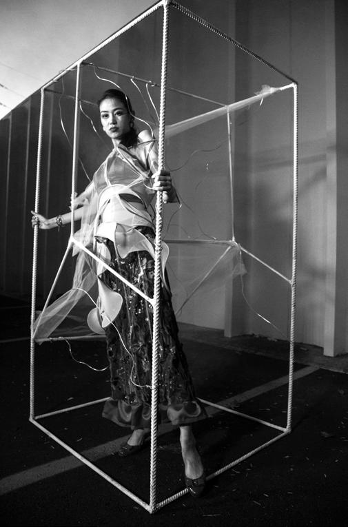


GROW GROW
THRIVE THRIVE
DANCE DANCE
90 91 FINAL LINE-UP GT X SCAD
PRODUCTION PLAN | A SECTION FINAL INSTALLATION HUNTHUNT


