XLOCK Smart


PACKAGING UNIT
(PAGE 3)
OVERVIEW
(PAGES 4-5)
DIMENSIONS
(PAGE 6)
TECHNICAL SPECIFICATIONS
(PAGE 7)
RELAY
(PAGE 8-11)
POWER SUPPLY
(PAGE 12)
CABLE CLAMPS
(PAGE 13)
ASSEMBLY (PAGES 14 - 16)
XLOCK APP
(PAGE 17)
GENERAL INFORMATION
(PAGE 18)

Standard content
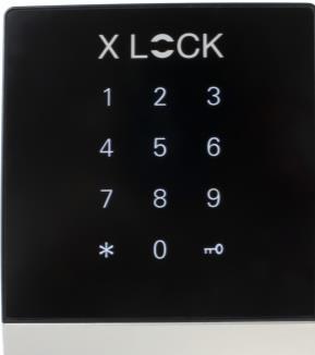
1) Smart Wall Reader SWR01
2) Flush-mounted mounting frame

Optional
3) XLOCK Timer relays

4) XLOCK Relay
5) XLOCK relay app controlled

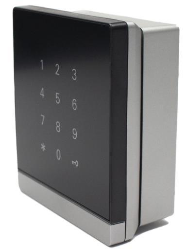
6) Smart Wall Reader SWR02


7) Surface mounted mounting frame

8) XLOCK Relay box
9) Netzteil 9V DC


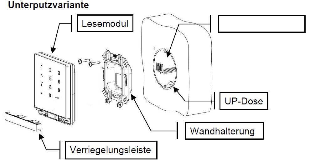
Reading module
Connection cable
Cavity wall socket
Flush-mounted mounting frame
Locking bar
Reading module

Connection cable
Locking bar
Aufputzdose
Surface mounted mounting frame

Flush-mounted version


Surface mounted variant


Dimensions (HxWxD)
Flush-mounted
Aufputz 101 x 88 x 35 mm 101 x 88 x 41 mm
Weight
Flush-mounted
Aufputz 140 g 160 g
Operating temperature -25˚C bis +60˚C
Humidity 20% to 75% relative humidity, non-condensing
Compatible with RFID ISO14443a, Mifare® Classic & Desfire, PIN Code, XLOCK App, XLOCK Gateway, XLOCK Cloud
IP-Code Front side (in mounted state) IP 54 - The reader is suitable for direct outdoor mounting
Input 9V DC - Netzteil
Number of Users Pin code, BLE/NFC tag: up to 200 users, smartphone number unlimited
Read range • < 25mm with XLOCK cards, other cards or transponders may have shorter or modified read range.
• Up to 15m with Bluetooth Low Energy
Signal elements Backlit glass surface as keypad, loudspeaker for acoustic signalization, 1 output for the XLOCK relay box
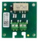
The relay box is an optionally available accessory for the wall reader. It is equipped with a 3V DC relay. Ideally suited for the control of electronic devices which open with a short potentialfree contact. For example: garage doors, barriers, motor locks, wired furniture locks, automatic doors, etc.

The connection in the relay box contained relay board is made via a 4-pole screw terminal according to the table below.
A maximum cable length of 5 meters with a cable cross-section of min. AWG 24 (approx. 0.2 mm²) and max. AWG 16 (approx. 1.3 mm²) must be observed!


Installation example. The relay box should be placed in a secured area.

Installation:

The Hensel junction box is fixed to the wall with two screws, wiring/connection according to terminal assignment on page 8. If necessary, cut out the cable duct wall of the junction box at the perforated surface and use the supplied insertion plugs for proper cable routing. Fix the cables with the cable ties supplied = strain relief.

The time-controlled relay is also an optionally available accessory for the wall reader. With this relay, a time delay can be defined in which the relay makes a potential-free contact. The default setting is 5 seconds (mode: P-4).

The duration can be changed as follows: Press Set key for a long time, select P-4 with the UP/DOWN keys and confirm with SET. "OP" starts flashing, with the UP/DOWN keys the desired time (0.1 seconds - 999 minutes) can now be set. To confirm, press SET for a long time, the display stops flashing. The settings have been accepted.

The APP controlled relay is an accessory for the XLOCK wall reader SWR01. With this relay the unlocking time or the toogle mode or the passage mode can be defined via the XLOCK APP in the settings of the wall reader. The relay switches a potential-free contact. Fields of application: Electric door openers, garage doors, barriers, motor locks, wired furniture locks, automatic doors, etc.
APPRELAIS with 12VDC power supply
A cavity wall box with Ø 68 mm and 60 mm (diagonal) device screw spacing is ideal for wall reader flush mounting. A mounting depth of 35 mm is sufficient.
Important: Before connecting the electronics, the polarity and voltage must be checked! A +9V DC power supply is correct. If the voltage is too high or the polarity is incorrect, the wall reader will be destroyed. There is no guarantee/warranty for this error.
Tip: If -9V DC is displayed on the meter, the poles are reversed.

Connect cable clamps - see picture.
The cables are now prepared.

Attention! „Top“ Pay attention to the labelling!
The flush-mounted mounting frame screw onto the cavity wall box,
Tip: The label "Top" shows the mounting direction – see photo.

Attach the cables of the wall reader to the clamps.
Attention: Note the poles: On the wall reader, the black cable is the negative pole, and the red cable is the positive pole.


The Smart wall reader is now completely installed. With a swipe over the number field, the wall reader is "woken up" and can be linked to our XLOCK app for approx. 5 seconds.


Tip: If the reading field switches off too quickly, simply wake it up again (*key press).
The exact procedure is described in the App Guide - click here or scan QR code:

The wall reader is not 100% waterproof (IP 54 ) and therefore requires a rain cover in unprotected locations. We have a rain cover as an optional accessory - see photo. If the wall reader still gets wet, it must be dried off quickly.
Optional ! Please order separately.
XLOCK Rain cover for wall reader SWR01
XL-RS-SWR01
Stainless steel housing as rain cover for the SWR01 wall reader. The rain cover is screwed onto the wall reader with the mounting holes.

The rain cover protects the wall reader from above and from the side.
Optional ! Please order separately.
With the wireless key, the lock can be unlocked over a distance of up to 20 meters - cable-free


XLOCK BLE
Wireless key


Optional ! Please order separately. Further


The normal reading distance depends on the respective reading system, the installation environment and the data carrier design. If the reader is mounted directly on metal, the reading distance may be slightly reduced. The following is a list of points that reduce the reading distance:
• „Shading" or shielding of the data carrier by metal, e.g. EC card in a wallet, key fob on a key ring.
• Not optimal coupling, i.e. the antenna surface of the data carrier is perpendicular (90°) to the antenna surface of the reader.
• Data carrier itself; key fob (small active antenna surface - "bad" resonance of the data carrier) - Combination ID card (e.g. LEGIC® / inductive, Mifare/Inductive etc.)
• Metal in the "active" effective area of the HF field. The transmitting energy is attenuated. This point is particularly relevant when installing the reader components in metal front panels (also metal columns, etc.).
The readers can interfere with each other or be negatively influenced by other systems and sources of interference. The readers can still interfere with each other at a distance of approx. two to three times the reading distance. High-energy interference sources in the range of the modulation and carrier frequencies can also interfere with the transmission.
When supplying power to the readers (especially over long distances), ensure that the cable cross-section is sufficient. Since the current consumption of the individual systems is partly pulse-shaped, short-term voltage drops cannot be detected with a conventional multimeter (digital or analogue). However, these voltage drops can cause a "POWER-ON-RESET" at the reader component, which can lead to communication problems. When dimensioning the power supply and the wire crosssections of the cabling, the maximum current consumption must therefore be taken into account. It is essential to ensure that the input voltage (measured at the reader) corresponds to the technical specifications of the reader.
Do not use sharp objects (rings, fingernails, etc.) on the unit!
Do not use corrosive or plastic-decomposing liquids such as petrol, turpentine, nitro etc. for cleaning. Harsh cleaning agents can damage or discolour the surface. Do not use cleaning agents that work on a mechanical basis (e.g. scouring powder, scouring sponge).
Clean with a soft, damp microfibre cloth. Only use clear water.
