
Previous Screen
Product: WHEEL LOADER
Model: 980H WHEEL LOADER MHG
Configuration: 980H Wheel Loader MHG00001-UP (MACHINE) POWERED BY C-15 Engine
Disassembly and Assembly
980H Wheel Loader Power Train
Torque Converter (Freewheel Stator) - Disassemble
SMCS - 3101-015
Disassembly Procedure
Table 1
Required Tools
Forcing Screw
3/8 - 16 x 3 in
Start By:
A. Separate the torque converter from the transmission and from the output transfer gears. Refer to Disassembly and Assembly, "Torque Converter from Transmission, Output Transfer Gears - Separate" for the machine that is being serviced.
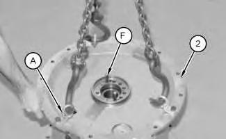
1. Place the torque converter housing assembly (2) on wood blocks.
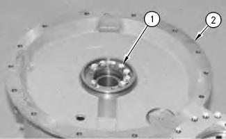
Illustration 1 g00503225
2. Remove bolts (1) and the washers from torque converter housing assembly (2) .
Illustration 2 g01111329
3. Install Tooling (A) to torque converter housing assembly (2) , as shown. Attach a suitable lifting device to Tooling (A) . The weight of housing assembly (2) is approximately 120 kg (265 lb).
4. Use Tooling (F) to loosen housing assembly (2) from the torque converter.
5. Remove housing assembly (2) from the torque converter.
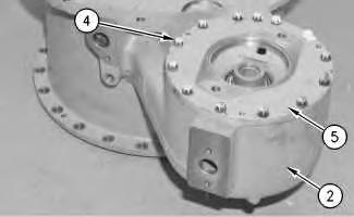
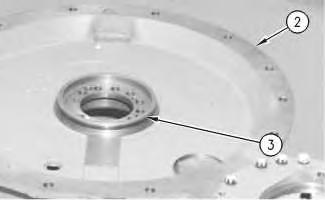 Illustration 3 g00871317
6. Remove O-ring seal (3) from torque converter housing assembly (2) .
Illustration 4 g00871318
7. Remove bolts (4) and the washers from pump adapter (5) and torque converter housing assembly (2) .
Illustration 3 g00871317
6. Remove O-ring seal (3) from torque converter housing assembly (2) .
Illustration 4 g00871318
7. Remove bolts (4) and the washers from pump adapter (5) and torque converter housing assembly (2) .
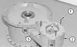

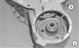 Illustration 5
g00871264
8. Use Tooling (F) to remove pump adapter (5) from torque converter housing assembly (2) .
Illustration 6
g00871319
9. Use tooling (C) to remove bearing cup (6) , O-ring seal (8) , and shims (7) from pump adapter (5) . See illustration 13 for Tooling (C) .
Illustration 7
g00871326
Illustration 5
g00871264
8. Use Tooling (F) to remove pump adapter (5) from torque converter housing assembly (2) .
Illustration 6
g00871319
9. Use tooling (C) to remove bearing cup (6) , O-ring seal (8) , and shims (7) from pump adapter (5) . See illustration 13 for Tooling (C) .
Illustration 7
g00871326
10. Remove pump drive gear (9) from torque converter housing assembly (2) .
11. Use Tooling (B) to remove bearing cones (10) from each side to pump drive gear (9) .


9
12. Use Tooling (C) to remove bearing cup (11) from torque converter housing assembly (2) . See illustration 13 for Tooling (C) .
Illustration 8 g00871451 Illustration g00871333Illustration 10
g01112900
13. Remove bolt (12) and the washer from torque converter housing assembly (2) .
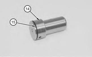
14. Use Tooling (F) to push shaft assembly (14) out of torque converter housing assembly (2) .
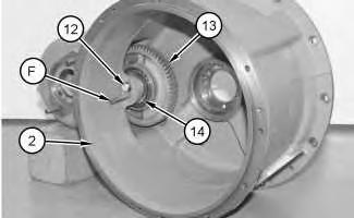
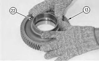
15. Remove idler gear (13) from torque converter housing assembly (2) .
Illustration 11
g01112903
16. Remove O-ring seal (15) from shaft assembly (14) .
Illustration 12 g00871365
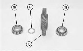
17. Remove bearing cone (16) , bearing cone spacer (17) , and bearing cone (18) from idler gear (13) .
Illustration 13 g00871366
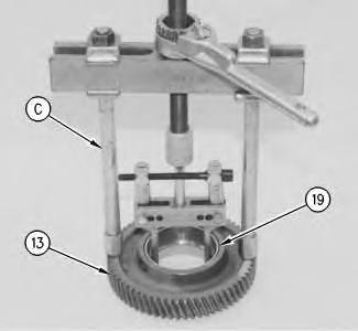
18. Use Tooling (C) to remove bearing cup (19) from idler gear (13) .

14 g00871367
19. Remove bearing cup spacer (20) from idler gear (13) .
Illustration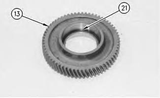
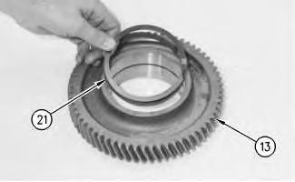
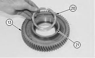
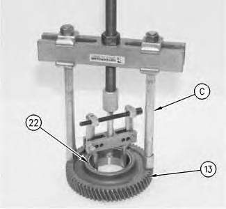 Illustration 15
g00871368
20. Remove retaining ring (21) from idler gear (13) .
Illustration 16
g00871369
21. Use Tooling (C) to remove bearing cups (22) from idler gear (13) .
Illustration 15
g00871368
20. Remove retaining ring (21) from idler gear (13) .
Illustration 16
g00871369
21. Use Tooling (C) to remove bearing cups (22) from idler gear (13) .
Illustration 17 g00871370
22. Remove studs (23) from torque converter housing assembly (2) .


Illustration 18 g00871267
23. Remove retaining ring (24) and bearing carrier (25) from the carrier assembly.
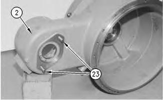
Illustration 19 g01112906
24. Remove bearing carrier (25) .
25. Remove O-ring seal (26) from bearing carrier (25) .
26. Remove seal ring (27) from ring carrier (28) .
27. Use Tooling (D) and a press to remove ring carrier (28) from bearing carrier (25) .

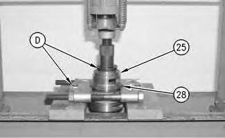
 Illustration 20 g00871269
Illustration 21 g00871273
Illustration 20 g00871269
Illustration 21 g00871273
Illustration 22
g00871274
28. Remove retaining ring (29) from bearing carrier (25) .
Illustration 23 g00871275
29. Use Tooling (D) and a press to remove inner bearing (30) from bearing carrier (25) .

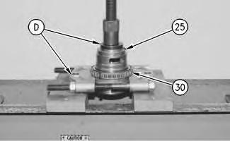
Illustration 24
g01112907
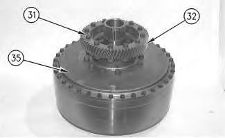
30. Remove bolts (31) and the washers from drive gear (32) .
31. Remove drive gear (32) .
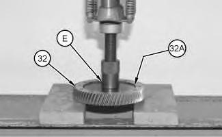
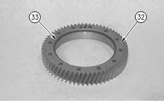
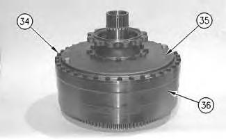 Illustration 25 g01112910
32. Use Tooling (E) and a press to remove the outer bearing race (32A) (not shown) from drive gear (32) .
Illustration 26 g00871278
33. Remove retaining ring (33) from drive gear (32) .
Illustration 27 g00871279
Illustration 25 g01112910
32. Use Tooling (E) and a press to remove the outer bearing race (32A) (not shown) from drive gear (32) .
Illustration 26 g00871278
33. Remove retaining ring (33) from drive gear (32) .
Illustration 27 g00871279
34. Remove bolts (34) and the washers from drive flange (35) and rotating housing (36) .
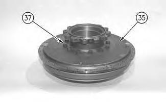
 Illustration 28 g00871281
35. Use bolts (34) as forcing screws to remove drive flange (35) from rotating housing (36) . The weight of drive flange (35) is 23 kg (51 lb).
Illustration 29 g00871282
36. Remove bolts (37) from drive flange (35) .
Illustration 28 g00871281
35. Use bolts (34) as forcing screws to remove drive flange (35) from rotating housing (36) . The weight of drive flange (35) is 23 kg (51 lb).
Illustration 29 g00871282
36. Remove bolts (37) from drive flange (35) .
Illustration 30 g00871283
37. Remove drive flange (35) from impeller (38) .

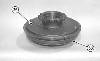
Illustration 31
g00871284
38. Position impeller hub (39) on wood blocks.
39. Remove impeller (38) from impeller hub (39) . Illustration

40. Remove thrust bearing (40) and race (40A) (not shown) from carrier assembly (41) .
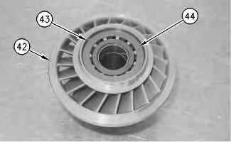
41. Remove carrier assembly (41) and stator (42) as a unit from rotating housing (36) .

42. Remove snap ring (43) from stator (42) . Remove plate (44) from stator (42) .
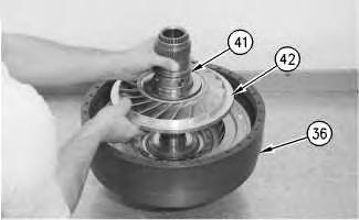 Illustration 33
g00870211
Illustration 34
g00870212
Illustration 33
g00870211
Illustration 34
g00870212
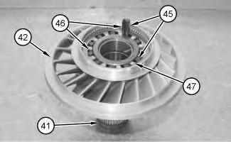
Illustration 35
43. Remove 11 freewheel rollers (45) and 11 freewheel springs (46) from freewheel cam (47) . Remove stator (42) from carrier assembly (41) .
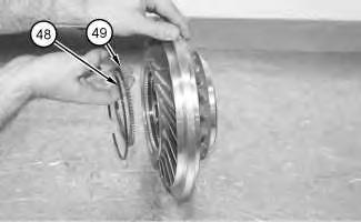
Illustration 36
44. Remove retaining ring (48) . Remove plate (49) .
45. Use Tooling (E) and a hydraulic press in order to remove freewheel cam (47) from stator (42) .
Note: If necessary, heat the stator to a maximum temperature of 135 °C (275 °F) for approximately 15 minutes.
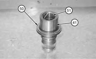
Illustration 37
46. Remove thrust bearing (50) from carrier assembly (41) . Remove sleeve bearing (51) from carrier assembly (41) .
Illustration 38
g01112919
47. Remove thrust bearing race (52) and the thrust bearing.
Illustration 39
g00870286
48. Remove turbine (53) and turbine hub (54) as a unit from rotating housing (36) .
Illustration 40
g01112920
49. Remove bolts (55) and the washers that hold turbine (53) to hub (54) .
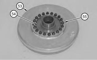


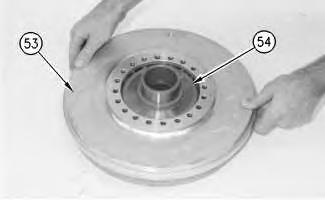
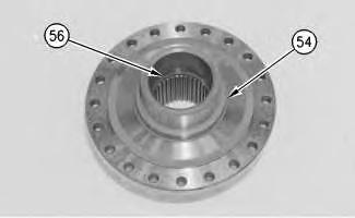
 Illustration 41
g00870755
50. Remove hub (54) from turbine (53) .
Illustration 42
g00870288
51. Remove retaining ring (56) from turbine hub (54) .
Illustration 41
g00870755
50. Remove hub (54) from turbine (53) .
Illustration 42
g00870288
51. Remove retaining ring (56) from turbine hub (54) .
Illustration 43 g01112924
52. Remove two races (57) and thrust bearing (58) .
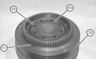
Illustration 44 g00870291
53. Remove bolts (59) and the washers from cover assembly (60) .
54. Remove cover assembly (60) from rotating housing (36) .
55. Remove ring seal (61) from rotating housing (36) .
Illustration 45 g00870294
56. Remove sleeve bearing (62) from cover assembly (60) . Copyright 1993 - 2021 Caterpillar Inc.


Previous Screen
Product: WHEEL LOADER
Model: 980H WHEEL LOADER MHG
Configuration: 980H Wheel Loader MHG00001-UP (MACHINE) POWERED BY C-15 Engine
Disassembly and Assembly
980H Wheel Loader Power Train
Torque Converter (Freewheel Stator) - Assemble
SMCS - 3101-016
Assembly Procedure Table 1
Required Tools
Note: Cleanliness is an important factor. Before assembly, thoroughly cleaned in cleaning fluid. Allow the parts to air dry. Wiping cloths or rags should not be used to dry parts. Lint may be deposited on the parts which may cause later trouble. Inspect all parts. If any parts are worn or damaged, use new parts for replacement.
Note: Apply oil to all of the bearings before assembly.
g01112937
1. Use Tooling (H) to install sleeve bearing (62) in cover assembly (60) . Sleeve bearing (62) must be even with the outside surface of cover assembly (60) .
g03337064
2. Install ring seal (61) to rotating housing (36) .
3. Install cover assembly (60) to rotating housing (36) .
4. Install bolts (59) and the washers to cover assembly (60) . Tighten the bolts to a torque of 30 ± 5 N·m (22 ± 4 lb ft).
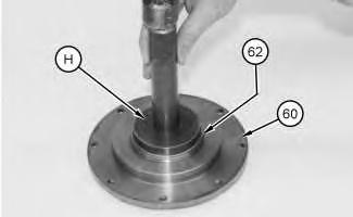 Illustration 1
Illustration 2
Illustration 1
Illustration 2
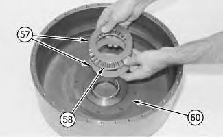
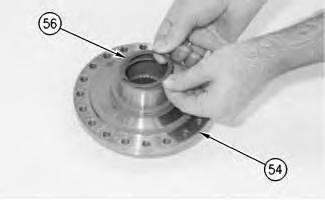 Illustration 3
g00870744
5. Install races (57) and thrust bearing (58) to cover assembly (60) .
Illustration 4
g00870748
6. Install retaining ring (56) in turbine hub (54) .
Illustration 5
g00870755
7. Install turbine (53) on hub (54) .
Illustration 3
g00870744
5. Install races (57) and thrust bearing (58) to cover assembly (60) .
Illustration 4
g00870748
6. Install retaining ring (56) in turbine hub (54) .
Illustration 5
g00870755
7. Install turbine (53) on hub (54) .
Illustration 6
g00870757
8. Install bolts (55) and the washers to turbine (53) . Tighten the bolts to a torque of 50 ± 7 N·m (37 ± 5 lb ft).

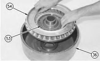

Illustration 7
g00870759
9. Install hub (54) and turbine (53) as a unit to rotating housing (36) .
Illustration 8
g00870760
10. Install thrust bearing race (52) and the bearing to the turbine hub (54) .
Illustration 9
g01112941
11. Use Tooling (H) and a hydraulic press in order to install sleeve bearing (51) to carrier assembly (41) . Install thrust bearing (50) to carrier assembly (41) .

Illustration 10
g01112915
Illustration 11
g01112913
12. Use Tooling (H) and a hydraulic press in order to install freewheel cam (47) to stator (42) .
13. Install plate (49) to stator (42) . Install retaining ring (48) to stator (42) .
Note: If necessary, heat stator (42) to a maximum temperature of 135 °C (275 °F). Install the cam with the IMPELLER SIDE facing downward. Continue with the installation until freewheel cam (47) contacts the retaining ring (not shown).
14. Install stator (42) to carrier assembly (41) . Install freewheel springs (46) and freewheel rollers (45) to freewheel cam (47) . Always install new freewheel springs (46) and freewheel rollers (45) . Install freewheel springs (46) with the maximum number of loops in freewheel springs (46) to the outside of freewheel cam (47) . Use the orientation of stator (42) in Illustration 11 in reference to the following statement: Stator (42) should turn freely in the clockwise direction. Stator (42) should not turn freely in the counterclockwise direction.
Illustration 12
g00870421
15. Install plate (44) to stator (42) . Install snap ring (43) to stator (42) .
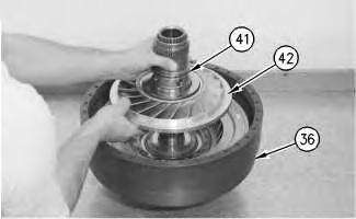
 Illustration 13
g00870422
16. Install carrier assembly (41) and stator (42) as a unit to rotating housing (36) .
Illustration 14
g00870762
17. Install thrust bearing (40) and race (40A) (not shown) to the carrier assembly (41) .
Illustration 15
g00870994
18. Position impeller hub (39) on a wood block.
Illustration 13
g00870422
16. Install carrier assembly (41) and stator (42) as a unit to rotating housing (36) .
Illustration 14
g00870762
17. Install thrust bearing (40) and race (40A) (not shown) to the carrier assembly (41) .
Illustration 15
g00870994
18. Position impeller hub (39) on a wood block.
 19. Install impeller (38) on impeller hub (39) .
Illustration 16 g00870995
20. Install drive flange (35) on impeller (38) .
Illustration 17 g00871000
21. Install bolts (37) on drive flange (35) . Tighten the bolts to a torque of 80 ± 10 N·m (60 ± 7 lb ft).
19. Install impeller (38) on impeller hub (39) .
Illustration 16 g00870995
20. Install drive flange (35) on impeller (38) .
Illustration 17 g00871000
21. Install bolts (37) on drive flange (35) . Tighten the bolts to a torque of 80 ± 10 N·m (60 ± 7 lb ft).
Illustration 18
g00871001
22. Install drive flange (35) on rotating housing (36) . The weight of drive flange (35) is approximately 23 kg (51 lb).
23. Install bolts (34) and the washers to drive flange (35) . Tighten the bolts to a torque of 30 ± 5 N·m (22 ± 4 lb ft).
g00871003
24. Install retaining ring (33) in the groove of drive gear (32) .
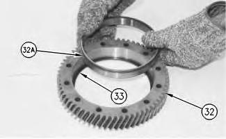
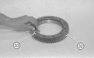 Illustration 19
Illustration 20 g00870829
25. Use the proper equipment to handle outer bearing race (32A) . Lower the temperature of outer bearing race (32A) .
26. Install outer bearing race (32A) in drive gear (32) . Make sure that outer bearing race (32A) contact retaining ring (33) .
Illustration 21 g00870763
27. Install drive gear (32) on drive flange (35) .
28. Install bolts (31) and the washers on drive gear (32) . Tighten the bolts to a torque of 50 ± 7 N·m (37 ± 5 lb ft).
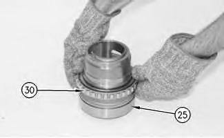
Illustration 22 g00871006
29. Use the proper equipment to handle inner bearing (30) . Heat inner bearing (30) to a maximum temperature of 135 °C (275 °F). Install inner bearing (30) on bearing carrier (25) .
Illustration 23
g00871007
30. Install retaining ring (29) in the groove of bearing carrier (25) .
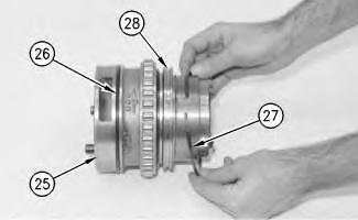

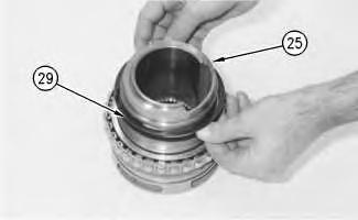
Illustration 24
g00871009
31. Use the proper equipment to handle ring carrier (28) . Heat ring carrier (28) to a maximum temperature of 135 °C (275 °F). Install ring carrier (28) on bearing carrier (25) .
Illustration 25
g00871012
Thank you very much for your reading. Please Click Here. Then Get COMPLETE MANUAL.NOWAITING

NOTE:
If there is no response to click on the link above, please download the PDF document first and then clickonit.
32. Install seal ring (27) on ring carrier (28) .
33. Install O-ring seal (26) on bearing carrier (25) .
Illustration 26
34. Install bearing carrier (25) in drive flange (35) .
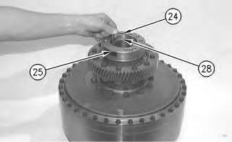
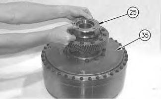
Illustration 27
35. Install retaining ring (24) and bearing carrier (25) on carrier assembly (28) .
g00871014 g00871015g00872709
36. Install studs (23) in torque converter housing assembly (2) . Tighten the studs to a torque of 100 ± 15 N·m (74 ± 11 lb ft).
g00872711
Illustration 28
Illustration 29
37. Install retaining ring (21) in the groove of idler gear (13) .
Illustration 30 g00872713
38. Use the proper equipment to handle bearing cup (22) . Lower the temperature of bearing cup (22) . Install bearing cup (22) in idler gear (13) .
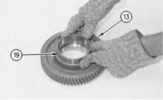
Illustration 31
39. Flip idler gear (13) to the opposite side. Install bearing cup spacer (20) in idler gear (13) . The notch in bearing cup spacer (20) must be aligned with retaining ring (21) .
Illustration 32
40. Use the proper equipment to handle bearing cup (19) . Lower the temperature of bearing cup (19) . Install bearing cup (19) in idler gear (13) .
 g00872715
g00872716
g00872715
g00872716