
Service
Previous Screen
Product: EXCAVATOR
Model: 311B EXCAVATOR 9MR
Configuration: 311B TRACK-TYPE EXCAVATOR 9MR00001-UP (MACHINE) POWERED BY 3064 ENGINE
Disassembly and Assembly
311B, 312B & 312B L EXCAVATORS MACHINE SYSTEMS
Swing Drive
SMCS - 4559-010; 5459-017

Remove & Install Swing Drive
Start By:
a. remove swing motor
Fluid Spillage Containment
Care must be taken to ensure that the fluids are contained during performance of the inspection, the maintenance, the testing, the adjusting and the repair of the machine. Be prepared to collect the fluid with suitable containers before opening any compartment or disassembling of the any components containing fluids. Refer to the "Tools And Shop Products Guide", NENG2500 for the tools and the supplies suitable to collect and contain any of the fluids in Caterpillar machines. Dispose of the fluids according to local regulations and mandates.
1. Thoroughly clean around the mounting area of the swing drive prior to removal.
2. Drain the oil from the swing drive into a suitable container. The capacity of the swing drive is 2.8 liters (.7 U.S. gal).
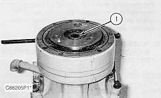
3. Remove 12 bolts (2) and the washers that hold swing drive (1) in position.
4. Fasten Tooling (A) and a hoist to the swing drive as shown.
5. Remove swing drive (1) from the machine. The weight of the swing drive is 98 kg (215 lb).
NOTE: The following steps are for the installation of the swing drive.
6. Thoroughly clean the mating surface of the main frame and swing drive housing.
7. Put 5P-3931 Anti-Seize Compound on location pin (3) in the main frame.
8. Put 1U-8846 Gasket Maker on the mating surface of the main frame and swing drive housing.
NOTE: During the installation, the locating pin for the swing drive may come out of the swing drive housing.
9. Fasten Tooling (A) and a hoist to swing drive (1). Put the swing drive in its original position on the main frame. If locating pin (3) comes out of the swing drive housing, it can be reinstalled with a hammer after the swing drive is in place.
10. Put 9S-3263 Thread Lock on the threads of 12 bolts (2). Install the 12 bolts and the washers that hold the swing drive in place.

NOTE: Refer to the topic "Lubricant Viscosities and Refill Capacities" in the "Operation & Maintenance Manual" for the proper filling procedure and the proper levels for the hydraulic oil system and swing drive.
11. After the installation of the swing motor, fill the hydraulic oil tank and the swing drive with oil to the correct levels.
End By:
a. install swing motor
Disassemble & Assemble Swing Drive
Start By:
a.

 remove swing drive
1. Install the swing drive on a suitable stand.
2. Remove sun gear (1) from the swing drive.
3. Remove carrier assembly (2) from the ring gear.
remove swing drive
1. Install the swing drive on a suitable stand.
2. Remove sun gear (1) from the swing drive.
3. Remove carrier assembly (2) from the ring gear.
4. Disassemble carrier assembly (2). Drive spring pin (3) into planetary shaft (4) with a hammer and a punch.
5. Remove planetary shaft (4), two thrust washers (5), and planetary gear (7) from the carrier. Remove bearing (6) from the planetary gear. Remove spring pin (3) from planetary shaft (4) with a hammer and a punch.


6. Remove the other two planetary gears from the carrier as in Steps 4 and 5.

7. Remove sun gear (8) from the carrier.
8. Remove snap ring (9) from sun gear (8).
9. Remove O-ring seal (10). Remove ring gear (11) from the swing housing.
10. Remove bolt (12) from the end of the pinion shaft.
11. Put the swing housing and the pinion shaft on its side as shown. Put an alignment mark on the cage and swing housing for assembly purposes. Remove eight bolts (13) and the washers that hold the cage with the pinion shaft to the swing housing.

NOTICE
To prevent damage to the pinion shaft during the removal with a press, put wood blocks under components.


12. Put the swing casing and the pinion shaft in a press as shown. Put wood blocks under the pinion shaft. Press the pinion shaft and the cage out of the swing housing as a unit. Remove carrier assembly (14). Remove the O-ring seal from the swing housing.
13. Remove retainer (15) from carrier assembly (14).
14. Remove bearing (16) from carrier assembly (14).
15. Disassemble carrier assembly (14). Drive spring pin (17) into planetary shaft (18) with a hammer and a punch.
16. Remove planetary shaft (18), two thrust washers (20), and planetary gear (19) from the carrier. Remove bearing (21) from the planetary gear. Remove spring pin (17) from planetary shaft (18) with a hammer and a punch.


17. Remove the other two planetary gears from the carrier as in Steps 15 and 16.

18. Remove spacer (22) from the pinion shaft by hand.

19. Remove shim (23) from the pinion shaft.
20. Remove pinion shaft (26) from bearing (24) and cage (25) with a press as shown. If necessary, remove the oil seal from the cage.


21. If necessary, remove two bearing races (27) from the swing housing. Remove drain pipe (28).
NOTE: The following steps are for the assembly of the swing drive.
22. Make sure all of the parts of the swing drive are thoroughly clean and free of dirt and debris prior to assembly.
23. If removed, install two bearing races (27) in the swing housing. Install drain pipe (28).
NOTE: Do not install the oil seal in cage (25) at this time.
24. Install cage (25) and bearing (24) on pinion shaft (26). Put spacer (23) over the pinion shaft.
25. Install spacer (22) over the pinion shaft.
26. Make sure the mating surfaces of the cage and the swing housing are clean and free of dirt and debris. Put a bead of 1U-8846 Gasket Maker on the mating surface of the cage. Install the cage with the pinion shaft in the swing housing. Make sure the alignment marks made on each component during disassembly line up with each other. Install bolts (13) and the washers that hold the cage and pinion shaft to the swing housing. Tighten the bolts to a torque of 33 ± 3.5 N·m (24 ± 2 lb ft).
27. Put a thin coat of clean SAE 30 weight oil on bearing (16). Install bearing (16) in the swing housing with a plastic hammer. Make sure the bearing is seated against the counterbore in the swing casing.
28. Assemble carrier assembly (14).
a. Put clean SAE 30 weight oil on bearing (21).
b. Install bearing (21) in planetary gear (19).
c. Install a thrust washer (20) on each side of the planetary gear.
d. Install the planetary gear and the thrust washers in the carrier.
e. Install planetary shaft (18) in carrier (14) and through planetary gear (19).
f. Make sure the spring pin hole in the planetary shaft is in alignment with the spring pin hole in the carrier.
g. Install spring pin (17) in the carrier and into the planetary shaft.
h. Install the spring pin until it is 2 to 3 mm (.078 to .118 in) below the outside surface of the carrier, and with the split in the spring pin facing toward the top or the bottom of the carrier. To prevent the spring pin from falling out, make a stake mark on each side of the spring pin hole in the carriage. Each stake mark should be approximately 1.5 mm (.10 in) from the spring pin hole.
29. Install the remaining planetary gears in carrier (14) as in Step 28.
30. Install retainer (15) to carrier (14).
31. Use two persons to install carrier assembly (14) over the end of the pinion shaft. Make sure the carrier assembly is completely seated. It may be necessary to use a press to seat the carrier assembly.

32. Install bolt (12) to the pinion shaft. Tighten the bolt to a torque of 314 ± 20 N·m (230 ± 15 lb ft).
33. Using bolt (12) check the bearing rolling torque. The bearing rolling torque should be 3.14 ± 1.26 N·m (2 ± 1 lb ft). If the bearing rolling torque is not within specification, spacers (22) and/or (23) need to be changed. Refer to the Specifications for 311B, 312B and 312B L Excavators, Hydraulic Systems for spacer part numbers and thicknesses.
34. When the proper bearing rolling torque is reached the following needs to be done.

35. Disassemble the swing drive, and install the oil seal in cage (25). Put a thin coat of 5P-0960 Multipurpose Grease on the sealing lip.
36. Reassemble the swing drive. Follow steps 23 thru 32.
37. Apply 9S-3263 Thread Lock on the threads of bolts (13). Tighten the bolts to a torque of 33 ± 3.5 N·m (24 ± 2 lb ft).
38. Apply 9S-3263 Thread Lock on the threads of bolts (12). Tighten the bolts to a torque of 314 ± 20 N·m (230 ± 15 lb ft).
39. Install the O-ring seal on the swing housing.
40. Install ring gear (11) in its original position on the swing housing. Put O-ring seal (10) on the ring gear.
41. Install snap ring (9) on sun gear (8).
42. Assemble carrier assembly (2).
a. Put clean SAE 30 weight oil on bearing (6).
b. Install bearing (6) in planetary gear (7).
c. Install a thrust washer (5) on each side of the planetary gear.
d. Install the planetary gear and the thrust washers in carrier (2).
e. Install planetary shaft (4) in carrier (2) and through planetary gear (7).
f. Make sure the spring pin hole in the planetary shaft (4) is in alignment with the spring pin hole in the carrier.
g. Install spring pin (3) in the carrier and into the planetary shaft.
h. Install the spring pin until it is 2 to 3 mm (.078 to .118 in) below the outside surface of the carrier, and with the split in the spring pin facing toward the top or bottom of the carrier.
i. To prevent the spring pin from falling out, make a stake mark on each side of the spring pin hole in the carrier.
j. Each stake mark should be approximately 1.5 mm (.10 in) from the spring pin hole.
43. Install the other two planetary gears in carrier (2) as in Step 42.
44. Use two persons to install carrier assembly (2) in the ring gear. Make sure the carrier assembly is not tilted after installation.
45. Install sun gear (1) in carrier assembly (2).
NOTE: Refer to the topic "Lubricant Viscosities and Refill Capacities" in the "Operation & Maintenance Manual" for the proper filling procedure and the proper levels for the swing drive.
46. Fill the swing drive with clean oil prior to installation of the swing motor.
End By: a. install swing drive
Copyright 1993 - 2020 Caterpillar Inc. All Rights Reserved. Private Network For SIS Licensees.
Previous Screen
Product: EXCAVATOR
Model: 311B EXCAVATOR 9MR
Configuration: 311B TRACK-TYPE EXCAVATOR 9MR00001-UP (MACHINE) POWERED BY 3064 ENGINE
Disassembly and Assembly
311B, 312B & 312B L EXCAVATORS MACHINE SYSTEMS
Undercarriage Frame Assembly
SMCS - 4150-010
Remove & Install Undercarriage Frame Assembly
Start By:
a. remove bucket
Fluid Spillage Containment
Care must be taken to ensure that the fluids are contained during performance of the inspection, the maintenance, the testing, the adjusting and the repair of the machine. Be prepared to collect the fluid with suitable containers before opening any compartment or disassembling of the any components containing fluids. Refer to the "Tools And Shop Products Guide", NENG2500 for the

tools and the supplies suitable to collect and contain any of the fluids in Caterpillar machines. Dispose of the fluids according to local regulations and mandates.

1. Position the machine on a level surface. Dimension "X" is equal to 907 mm (36 in).
2. Position drain plug (1) for each final drive in the position shown. Drain the oil from each final drive into a suitable container. The capacity of each final drive is 2.5 to 2.6 liters (.6 to .7 U.S. gal).
3. Remove bolts (2) and cover (3) from each final drive.
When sun gear (4) is removed from each final drive, the brakes for the machine are inoperable. The machine is free to move. To prevent movement of the machine, put wood blocks in front of and behind each track assembly.


4. Remove sun gear (4) from each final drive.
5. Temporarily reinstall cover (3) back on each final drive.
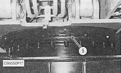
6. Loosen, but do not remove bolts (5) that hold the undercarriage frame assembly to the upper structure. Swing the upper structure to gain access to all of the bolts.

7. Remove right hand boom cylinder (6) from the machine. Refer to the topic "Remove & Install Boom Cylinders" in this module. Put caps in the hydraulic lines that connect to the right hand boom cylinder.
8. Start the machine. Raise the boom until the center of the pin bore for the bucket-to-stick pin joint is approximately 907 mm (36 in) off the floor.

NOTICE
Do not lower the boom after Tooling (A) has been installed in place of the right hand boom cylinder.
9. Adjust the length of Tooling (A), and install it in place of the right hand boom cylinder. Install the five bolts, the washers and the nuts to hold the link group together.
NOTICE
Do not position Tooling (B) under the counterweight of the machine. Position it only under the main frame.

11. Install Tooling (B) under the main frame at the rear of the machine as shown.


 10. Install Tooling (B) under the stick as shown.
12. Remove four hose assemblies (7) from the swivel joint.
13. Remove two hose assemblies (8) and (9) from the swivel joint.
10. Install Tooling (B) under the stick as shown.
12. Remove four hose assemblies (7) from the swivel joint.
13. Remove two hose assemblies (8) and (9) from the swivel joint.
14. Remove locking bolt (11) from the swivel joint.
15. Loosen hose clamp (10).
16. Disconnect grease tube assembly (12) from the block on the frame of the upper structure.
17. Remove all bolts (5) that hold the upper structure to the undercarriage frame assembly.


During the removal, the upper structure must be kept in a level position at all times.
18. Raise the upper structure off of the undercarriage frame assembly with tooling (B) in 13 mm (.5 in) increments. Raise the upper structure until it is above swivel joint group (13). Adjust the height of Tooling (B) at the same time to keep the upper structure level. The weight of the upper structure is approximately 726 kg (16,000 lb).
NOTE: The boot on the swivel joint group is very flexible. This will allow the swivel joint to slide thru it as the upper structure is being raised.

19. Fasten a chain to the rear of the undercarriage frame assembly (14). Pull the undercarriage frame assembly out from under the upper structure with a lift truck. Check the clearance between the upper structure and the swivel joint during the removal procedure. The weight of the undercarriage frame assembly is approximately 5000 kg (11,000 lb).
NOTE: The following steps are for the installation of the undercarriage frame assembly.
20. Make sure the mating surfaces of the upper structure and undercarriage frame assembly are thoroughly clean and free of dirt and debris.
21. Install two suitable size guide bolts (15) in the mounting bolt holes in the upper structure and the undercarriage frame assembly as shown. Install the guide bolts 180 degrees apart.
22. Put a coat of 1U-8846 Gasket Maker on the mating surface of the swing gear and bearing of the undercarriage assembly. Put 5P-3931 Anti-Seize Compound in the locating dowel hole in the undercarriage frame assembly.
23. Using a lift truck, move undercarriage frame assembly (14) in position under the upper structure. Block the undercarriage frame assembly so it can not move.
NOTICE
When the upper structure is installed, do not damage the tooth contact surfaces of the pinion shaft and the swing gear and bearing. Keep the upper structure level as it is being lowered into position.
24. Remove the pins from the tubes of Tooling (B). Lower the upper structure down in 13 mm (.15 in) increments with Tooling (B). Align the guide bolts in the upper structure with the bolt holes in the undercarriage frame assembly. Move the undercarriage frame assembly to obtain proper alignment.
25. As the upper structure is being lowered, check the alignment of the pinion shaft with the swing gear and bearing. Also, check the alignment of the dowel in the upper structure with the dowel hole in the swing gear and bearing.

26. Put a coat of 9S-3262 Thread Lock Component on the threads of all bolts (5) that hold the upper structure to the undercarriage frame assembly. Install all bolts (5) and tighten the bolts that are easily accessible to a torque of 270 ± 40 N·m (200 ± 30 lb ft).
27. Connect grease tube assembly (12) to the block on the front of the upper structure.
28. Reinstall clamp (10) over swivel boot. Reinstall two hose fittings (8) and (9) in swivel joint group.
29. Reinstall lock bolt (11) in the swivel group.
30. Connect four hose assemblies (7).
31. Remove Tooling (A) from the machine.
NOTE: Refer to the topic "Lubricant Viscosities and Refill Capacities" in the "Operation & Maintenance Manual" for the proper filling procedure and the proper levels for the hydraulic oil system.
32. Fill the hydraulic oil tank with oil to the correct level.
33. Start the machine, and straighten it out.
34. Reinstall right hand boom cylinder (6). Refer to the topic "Remove & Install Boom Cylinders" in this module.
35. Remove Tooling (B) from under the rear of the machine.
36. Remove Tooling (B) from under the stick.
37. Install the remainder of bolts (5). The machine can be rotated to the left or right to make access to all bolts (5) easier. Tighten the bolts to a torque of 270 ± 40 N·m (200 ± 30 lb ft).
38. Remove cover (3) from each final drive.
39. Install sun gear (4) in each final drive.
40. Make sure the machined surface of the ring gear in the final drive and cover (3) is thoroughly clean, free of dirt and debris and is dry. Put a bead of 1U-8846 Gasket Maker around the machined surface of the ring gear. Put cover (3) in its original position on the ring gear.
41. Put 9S-3263 Thread Lock on the threads of bolts (2) that hold cover (3) in position. Install bolts (2) and the washers that hold the cover. Tighten the bolts to a torque of 29 ± 2 N·m (22 ± 2 lb ft).
NOTE: Refer to the topic "Lubricant Viscosities and Refill Capacities" in the "Operation & Maintenance Manual" for the proper filling procedure and the proper levels for each of the hydraulic drives.
42. Fill each final drive with oil to the correct level.
End By:
a. install bucket
Previous Screen
Product: EXCAVATOR
Model: 311B EXCAVATOR 9MR
Configuration: 311B TRACK-TYPE EXCAVATOR 9MR00001-UP (MACHINE) POWERED BY 3064 ENGINE
Disassembly and Assembly
311B, 312B & 312B L EXCAVATORS MACHINE SYSTEMS
Swing Gear & Bearing
SMCS - 7063-010

Remove & Install Swing Gear & Bearing
Start By:
a. remove undercarriage frame assembly

1. Put an alignment marks on the swing gear and bearing and the undercarriage frame assembly for assembly purposes. Remove bolts (2) and the spacers that hold swing gear and bearing (1) to the undercarriage frame assembly.
2. Fasten Tooling (A) and a hoist to the swing gear and bearing as shown. The bolts and the spacers used to hold the upper structure to the undercarriage frame assembly can be used to install Tooling (A).
3. Remove the swing gear and bearing. The weight of the swing gear and bearing is 171 kg (376 lb).
Typical Example
4. Tape over the sealing surfaces of the dust seals, the inner race and the outer race. This will prevent cleaning solvent from entering the cross sections of the dust seals. Thoroughly clean the swing gear and bearing.
5. Remove dust seals (3) and (4) from the outer and the inner races of the swing gear and bearing.
6. Clean the sealing grooves of the inner and the outer races with fine grit sandpaper; then use a cleaning solvent to clean the seal grooves. Make sure the seal grooves are thoroughly clean and dry prior to installing new dust seals.
NOTE: The following steps are for the installation of the swing gear and bearing.
7. Lay a new dust seal (3) in the outer race to determine the required length. Cut the new seal approximately 1 cm (.4 in) shorter than the required length. Cut the seal at a 90 degree angle. Use a file to smoothen the cross section cut of the seal.
8. Install new dust seal (3) in the outer race using 8T-9021 Adhesive. Make sure to put adhesive on the 90 degree cross section of the seal. Install the seal with the lip facing as shown in Illustration C30014P1.
9. Install a new dust seal (4) in the inner race. Follow the same procedure as in Steps 7 and 8.

10. Lubricate the swing gear and the bearing with grease.
11. Clean the mating surfaces for the swing gear and bearing on the undercarriage frame assembly. Put 1U-8846 Gasket Maker on the mating surface. Fasten Tooling (A) and a hoist to swing gear and bearing (1), and put it in position on the undercarriage frame assembly. Make sure the stamp mark "S" on the inner race is positioned as shown, relative to the undercarriage frame assembly and the stopper on the outer race.

12. Put a thin coat of 2P-2506 Thread Lubricant on the threads of bolts (2). Install the spacers and bolts (2) that hold the swing gear and bearing to the undercarriage frame assembly. Tighten the bolts to a torque of 270 ± 40 N·m (200 ± 30 lb ft). If desired, Tooling (B) can be used to tighten the bolts.
End By:


 3. Remove two bolts (1) and the washers that secure plate (2). Remove plate (2).
6. Remove two bolts (6) and the washers that secure cover (7) to the machine. Remove cover (7).
3. Remove two bolts (1) and the washers that secure plate (2). Remove plate (2).
6. Remove two bolts (6) and the washers that secure cover (7) to the machine. Remove cover (7).


 View From Under Machine


 13. Loosen two hose clamps (17), and remove hose (18) from the hydraulic oil tank.
14. Disconnect electrical connector (19). Remove three wire ties (20) from the side of the hydraulic oil tank.
15. Remove bolts (21) and the washers that secures p-clamp (22) to the side of the hydraulic oil tank.
View From Under Machine
16. Remove six bolts (23) and the washers that secure that hydraulic oil tank to the frame.
13. Loosen two hose clamps (17), and remove hose (18) from the hydraulic oil tank.
14. Disconnect electrical connector (19). Remove three wire ties (20) from the side of the hydraulic oil tank.
15. Remove bolts (21) and the washers that secures p-clamp (22) to the side of the hydraulic oil tank.
View From Under Machine
16. Remove six bolts (23) and the washers that secure that hydraulic oil tank to the frame.


 frame of the machine.
20. Install P-clamp (22) and bolt (21) that secures it.
frame of the machine.
20. Install P-clamp (22) and bolt (21) that secures it.


 26. Install side cover (10) and three bolts (9).
27. Install bolt (8).
28. Install front cover (7) and two bolts (6) that secure it.
29. Install support (5) and three bolts (4) that secure it.
30. Install two bolts (3) that secure the governor motor control to support (5).
26. Install side cover (10) and three bolts (9).
27. Install bolt (8).
28. Install front cover (7) and two bolts (6) that secure it.
29. Install support (5) and three bolts (4) that secure it.
30. Install two bolts (3) that secure the governor motor control to support (5).


