
Previous Screen
Product: WHEEL LOADER
Model: 926 WHEEL LOADER 8NB
Configuration: 926E WHEEL LOADER 8NB01542-02451 (MACHINE) POWERED BY 3204 ENGINE
Disassembly and Assembly
926 WHEEL LOADER VEHICLE SYSTEMS
Hydraulic Pump
SMCS - 5055-010; 5055-015; 5055-016
Remove And Install Hydraulic Pump
START BY:
a. remove cab right side lower shroud
To prevent personal injury, release the pressure from the hydraulic system before any hoses are disconnected or removed.
1. Drain the oil from the hydraulic tank. The capacity of the hydraulic tank is 53 liter (14 U.S. gal.).
2. Remove right side rear fender.
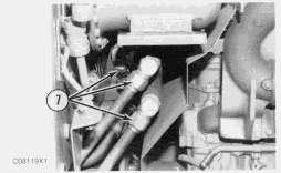
3. Disconnect clip (1) that holds the wiring harness to the support.
4. Remove strip (2).
5. Remove tubes (3).

6. Thoroughly clean the tube connections at the hydraulic pump to prevent dirt entry into the hydraulic pump.
7. Disconnect tubes (4), (5) and (6) at the hydraulic pump.


8. Remove the bolts that hold hydraulic pump (7) to the engine. Use two persons, and remove the pump. The weight of the pump is 30 kg (66 lb.).
9. Put protective covers in the hydraulic openings.
NOTE: The following steps are for installation of the hydraulic pump.
10. Remove the protective covers, and install a new O-ring seal on the hydraulic pump.
11. Be sure the O-ring seals are in place in tubes (4), (5) and (6).
12. Install the hydraulic pump.
13. Install the right side rear fender.
14. Fill the hydraulic system with oil to the correct level. See the Maintenance Guide.

END BY:
a. install cab right side lower shroud
Disassemble Hydraulic Pump
START BY:
a. remove hydraulic pump
1. For correct assembly of the parts, the pump rotation is in a clockwise direction as seen from the shaft end (drive end) of the hydraulic pump. Mark the relative position of the pump sections before disassembly.


NOTE: The pictures that follow show a pump with different orientation and rotation from the one used on 926 Wheel Loaders. However, the service procedure is the same.
2. Remove four bolts (1) that hold cover (2) to cover (3). Remove cover (2) and the cartridge assembly from the pump as a unit.

NOTE: Make a note of the direction of the arrows at locations (X) and (Y) and the location of bolts (4) for assembly purposes. Arrows at locations (X) and (Y) show the direction of pump rotation.
3. Remove cartridge assembly (5) and O-ring seal (6) from cover (2).
4. Remove seal ring (8) from the cartridge assembly.
5. Remove O-ring seal (7) and the back-up ring from the cartridge assembly.


 6. Remove bolts (4) and cover (9) from the cartridge.
7. Remove seals (10) and the retainers from cover (9).
8. Remove plate (11) from the cartridge.
9. Remove ring (13) and rotor assembly (12) from plate (14) as a unit.
10. Remove rotor assembly (12) from ring (13).
6. Remove bolts (4) and cover (9) from the cartridge.
7. Remove seals (10) and the retainers from cover (9).
8. Remove plate (11) from the cartridge.
9. Remove ring (13) and rotor assembly (12) from plate (14) as a unit.
10. Remove rotor assembly (12) from ring (13).
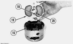
11. Remove vanes (16) and inserts (15) from the rotor.
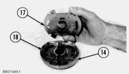
12. Remove plate (17) from end plate (14).
13. Remove seals (18) and the retainers from the end cover.
14. Remove bolts (19) and cover (20) from body assembly (21).


15. Remove cartridge assembly (22) and O-ring seal (25) from body assembly (21).
NOTE: Make a note of the direction of the arrows (23) nearest the bolts and the direction of the arrow (24) on the ring for assembly purposes.
16. Do Steps 4 through 13 again for the disassembly of cartridge (22).
17. Remove spiral snap ring (27), and remove the shaft assembly from the body.
18. Remove snap ring (28) from shaft (26).
19. Use tooling (A) and a press to remove shaft (26) from bearing (27).


20. Remove washer (29) and two lip-type seals (30) from the body.
21. Inspect all parts for wear or damage, and make replacements if necessary. If any parts with alignment marks are replaced, put new marks in the same location on the new parts.
Assemble Hydraulic Pump
1. Put clean oil on all parts at assembly.
NOTE: For correct assembly of all parts, the pump rotation is in a clockwise direction as seen from the shaft end (drive end) of the hydraulic pump.
2. Use tooling (A), and install lip-type seal in body (1). Install the seal with the lip down as shown.
3. Turn body (1) over, and install the lip-type seal with tooling (A). Install the seal with the lip up toward the cartridge assembly as shown.
4. Use tooling (B) and a press to install bearing (3) on shaft (2).


5. Install snap ring (4) that holds bearing (3) on the shaft.
6. Protect the seal lip with shim stock or plastic, and put washer (6) and shaft assembly (5) in position in body (1). Remove the shim stock or plastic.
7. Install spiral ring (7) that holds shaft assembly (5) in body (1).
NOTE: When vanes (15) are installed correctly, the rear edge of each vane is next to the balance opening (slot) in the rotor. The leading edge of each vane faces the direction of pump rotation (arrow).
10. Install inserts (14) and vanes (15) in rotor (13). The sharp edge of the vanes must be in the same direction as the arrow on the chamfer of ring (12). Each vane (15) must move freely in its slot in the rotor. Each insert (14) must move freely in its vane (15).


11. Put a large rubber band around rotor (13) to hold the vanes and inserts in the rotor.
 8. Put O-ring seals (8) in position in plastic retainers (9). Install seal assemblies on end plate (10) with the O-ring seal toward the end plate.
9. Put plate (11) in position on the end plate with the brass side up toward the rotor.
8. Put O-ring seals (8) in position in plastic retainers (9). Install seal assemblies on end plate (10) with the O-ring seal toward the end plate.
9. Put plate (11) in position on the end plate with the brass side up toward the rotor.
12. Put rotor assembly (17) in position on plate (11) as shown. Be sure the sharp edge of the vanes and the arrow on the chamfer of the ring are in the same direction.

13. Put ring (12) in position on plate (11) and end plate (10) as shown. The arrow on the chamfer of ring (12) must be in the same direction as the rotation of the rotor.
14. Put plate (16) in position on the cartridge assembly. Make sure the brass side of the plate is toward the rotor assembly. Also, make sure the notches on the outside diameter of plate (16) are in alignment with the notches on plate (11) and the chamfers on ring (12).
15. Put O-ring seals (18) in position in plastic retainers (20). Install seal assemblies on plate (19) with the O-ring seal toward plate (16).
16. Put plate (19) in position on the cartridge assembly as shown.
17. Install bolts (21) that hold plate (19) on the cartridge assembly. Install the bolts in the holes nearest to the arrows on the plate that show the direction of pump rotation.
18. Install O-ring seal (24); then back-up ring (25) on the end plate of cartridge assembly (22).

19. Install seal ring (23) on the end plate of cartridge assembly (22).
20. Install cartridge assembly (22) on the shaft assembly.
21. Install O-ring seal (28) in body assembly (1).
NOTE: Dowels (27) in the cartridge assembly must be aligned with the holes in cover (26).
22. Install cover (26) on body assembly (1). Use the original marks for alignment.

23. Install the bolts that hold the cover to the body, and tighten them to a torque of 95 ± 14 N·m (70 ± 10 lb.ft.).


24. Do Steps 8 through 16 again for the assembly of cartridge (30).
25. Install cartridge assembly (30) in cover (29).
26. Install O-ring seal (32) in cover (29).
NOTE: Dowels (31) in the cartridge assembly must be aligned with the holes in cover (26).
27. Put cartridge assembly (30) and cover (29) in position on cover (26) as a unit. Use the original marks for alignment.
28. Install bolts (33) that hold cover (29) to the cover, and tighten them to a torque of 61 ± 7 N·m (45 ± 4 lb.ft.).

END BY:
a. install hydraulic pump
Copyright 1993 - 2021 Caterpillar Inc.
All Rights Reserved. Private Network For SIS Licensees.
Sat Feb 20 17:11:34 UTC+0800 2021
Previous Screen
Product: WHEEL LOADER
Model: 926 WHEEL LOADER 8NB
Configuration: 926E WHEEL LOADER 8NB01542-02451 (MACHINE) POWERED BY 3204 ENGINE
Disassembly and Assembly

926 WHEEL LOADER VEHICLE SYSTEMS

Hydraulic Tank
SMCS - 5056-011; 5056-017
Remove And Install Hydraulic Tank
1. Remove the hood.
2. Remove the engine compartment doors.
To prevent personal injury, stop the engine, lower the bucket to the ground, move the control levers backward and forward to release the pressure in the hydraulic system. Slowly loosen the cap to release any pressure in the hydraulic tank. Let the hydraulic oil become cool before any lines are disconnected in the hydraulic system.
3. Drain the oil from the hydraulic tank. The capacity of the hydraulic tank is 53 liter (14 U.S. gal.).
4. Disconnect wire harness (1) from the hydraulic tank.


5. Remove the bolts and nuts that hold plate (2) to the hydraulic tank. Move plate (2) off the studs.
6. Disconnect hoses (3), (4) and (5) at the fittings on the hydraulic tank.

7. Fasten tooling (A), and a hoist to the hydraulic tank. The weight of the hydraulic tank is 104 kg (230 lb.).
8. Remove support (6).
9. Disconnect tube assemblies (7) at the fittings on the hydraulic tank.
10. Remove bolts (8) that hold the hydraulic tank to the support.
11. Lift hydraulic tank (9) straight up. Be careful not to damage the cab while removing the hydraulic tank.
12. Put protective covers over the hydraulic openings.
13. Remove the protective plugs, and install the hydraulic tank in the reverse order of removal. Tighten bolts (8) that hold the hydraulic tank to the support to a torque of 135 ± 15 N·m (100 ± 11 lb.ft.).


14. Fill the hydraulic tank to the correct level. See the Maintenance Guide.
15. Install the engine compartment doors.
16. Install the hood.
Disassemble And Assemble Hydraulic Tank
START BY:
a. remove hydraulic tank
1. Remove elbows (1), (2), (3) and (4) from the hydraulic tank. 2. Remove plate (5).3. Remove cover (6) and filter element (7).
4. Remove oil filter bypass valve (8).
5. Remove strainer (9) and strainer (10).
6. Inspect all parts, and replace as necessary. See Wheel Loader Hydraulic System Specifications for filter bypass valve spring data.
NOTE: The sight glass can be removed if necessary. Tighten the screws to a torque of 24 ± 3 N·m (18 ± 2 lb.ft.).
7. Tighten the filter element bolt to a torque of 56 ± 3 N·m (41 ± 2 lb.ft.).
8. Thoroughly clean the mating surfaces of the hydraulic tank and plate (5).
9. Assemble the hydraulic tank components in the reverse order as disassemble.

10. Peel the tape from a 300 cm (118 in.) piece of 3G4090 Sealant. Apply the sealant, adhesive side down to the hydraulic tank. Apply sealant (11) to the area of the tank flange between the inside edge of the flange and the holes. Overlap the ends of the sealant bead around a bolt hole as shown.
11. Install plate (5) on the hydraulic tank.

END BY:

Previous Screen
Product: WHEEL LOADER
Model: 926 WHEEL LOADER 8NB
Configuration: 926E WHEEL LOADER 8NB01542-02451 (MACHINE) POWERED BY 3204 ENGINE
Disassembly and Assembly
926 WHEEL LOADER VEHICLE SYSTEMS
Air Dryer
SMCS - 4285-010; 4285-015; 4285-016
Remove And Install Air Dryer
To prevent possible personal injury, make sure all the pressure is released from the air system before any lines are disconnected.
1. Disconnect two tube assemblies (1) and hose assembly (2).

2. Disconnect wire assembly (3).
3. Remove the two U-bolts, and remove air dryer (4).
NOTE: The following steps are for the installation of the air dryer.
4. Put the air dryer in position, and install two U-bolts (5). Tighten the nuts on the U-bolts to a torque of 25 ± 7 N·m (18 ± 5 lb.ft.).
5. Connect wire assembly (3). Tighten the nut holding the wire to 0.50 ± 0.05 N·m (4 ± 0.4 lb.in.).
6. Connect hose assembly (2) and two tube assemblies (1).


 15. Install two seals (28) on purge plate (26). Install desiccant spring (25), purge plate (26), seal washer (29), center shaft (27) and seal washer (29).


