WAVE SPRING TECHNOLOGY ADVANCES TO SATISFY TODAY’S APPLICATIONS
MOTION SYSTEM
HANDBOOK
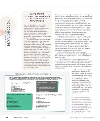
Piloting grooves or other geometry helps the wave spring stays in place. Distance between surfaces inducing load defines axial working cavity — and working spring height. This is where the spring’s material cross-section affects overall design. More specifically, the factors dictating suitable wavespring design include application load; bore geometry, shaft, According to Sanjeev Rivera of Lee ID, and OD; working height; and spring material to withstand Spring, there are some industry environmental factors. Other general guidelines are that the moves towards design miniaturization. wave-spring number of turns must be between two and 20; Wave springs excel here, thanks to express the number of waves per turn in half-turn increments; the way they deliver a given spring minimum radial wall is three times wire thickness; and force in significantly reduced space. maximum radial wall is 10 times the wire thickness. So designers can reduce finished Reconsider working height for a moment: Designs must assemblies’ size and weight through use avoid situations that compress a wave spring to solid. That’s of wave springs. because as a wave spring approaches a height at which it Wave springs have also benefitted from new availability of raw materials becomes solid (with the various turns contacting or wave turns and end configurations. Design flattened) loads increase exponentially and even become engineers should consider these designs unpredictable. These loads in turn can induce the spring wherever applications are subject to to take a set or relax. Magnitude of relaxation depends on weight or space restrictions. Designers load and other application conditions. In any case, material should understand that wave springs in deformation wll degrade spring performance. a sense act as stacked wave washers in More specifically, if a spring is going into a static series configuration — but without any application, ensure that percent stress at working height is less worries about maintaining alignment. than 100% because springs can take a set or lose length loss That’s because the wave-spring design under high stress. maintains alignment on its own. Unique wave-spring variations such as nested If a spring is going into a dynamic application, ensure and interlaced wave springs also exist percent stress at working height is less than 80% because again to incorporate advanced fatigue and — springs can take a set if subject to higher stress. If work load-rating characteristics. Application height per turn is less than twice the wire thickness, the spring of these geometries really depends on operates in a nonlinear range … and actual loads may exceed the assembly at hand. calculated loads. Most manufacturers only test standard wave at the loads and work heights specified in literature. FORMULAS FOR SPECIFYING A WAVE SPRING Usually they publish work heights that are the lowest recommended Here are basic formulas to narrow down the wave spring type, shape and size that best suit an application. Note that wave springs are helping today’s push toward design miniaturization. Smaller designs need shorter and smaller for a given spring … though diameter wave springs. That’s spurred some developers to make wave springs less than 0.250 in. in diameter. other heights maybe possible. But contact the manufacturer for Fatigue stress ratio x = (s - s1/(s - s2) 2 2 Operating stress S = (3πPDm)/4bt N analysis of spring characteristics at Where: Where: alternate heights. Manufacturers s = Material tensile strength S = Operating stress P = Load, lb s1 = Calculated operating stress at lower can sometimes help OEMs design Dm = Mean diameter, in. working height (not to exceed s) wave springs for applications b = Radial width of material, in. s2 = Calculated operating stress at t = Thickness of material, in. that cannot adhere to normal upper working height N = Number of waves per turn guidelines. Deflection f = ((PKZDm3)/(Ebt3N4)) x (ID/OD) Spring rate R = (P/f) = (Ebt3N4)/(KZDm3) x (ID/OD) Where: f = Deflection, in. P = Load, lb K = Multiple wave factor Dm = Mean diameter, in. Z = Number of turns E = Modulus of elasticity b = Radial width of material, in. t = Thickness of material, in. N = Number of waves per turn
166
DESIGN WORLD — MOTION
wave springs — Motion System Handbook 8-17 V3.LE.indd 166
: Where: R = Spring rate, lb/in. P = load, lb f = Deflection, in. b = Radial width of material, in. t = Thickness of material, in. N = Number of waves per turn K = Multiple wave factor Dm = Mean diameter, in. Z = Number of turns
8 • 2017
Here are some formulas to identify the most suitable wavespring type, size, and shape for an application. In fact, smaller designs and miniature wave springs (with diameters to less than 0.250 in.) along with material advancements are driving new applications for wave-springs that are more advanced than ever.
motioncontroltips.com | designworldonline.com
8/21/17 8:27 AM