














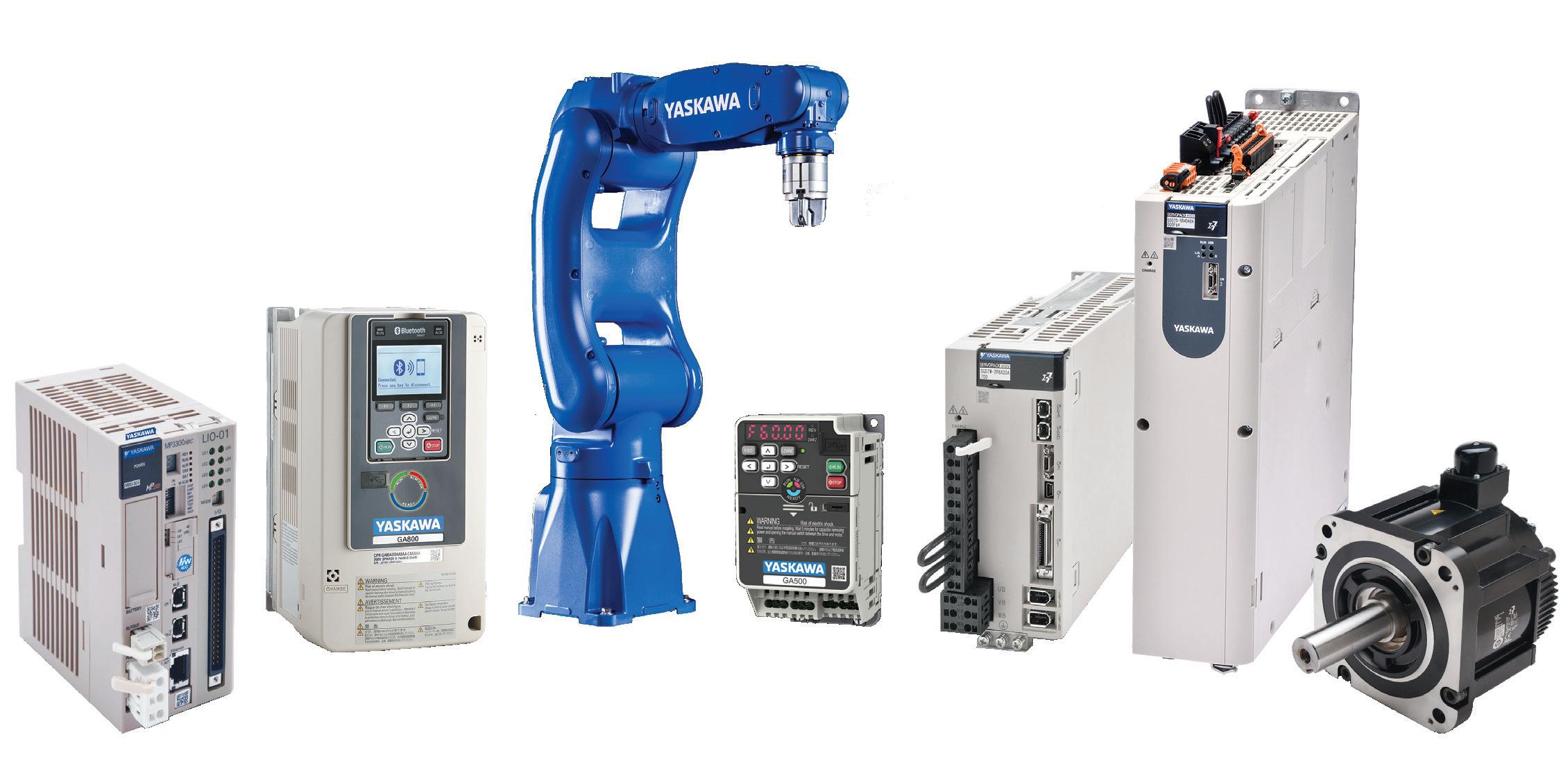
The quality of Yaskawa products is second to none, but Yaskawa Quality goes beyond that. It’s the total experience of purchasing Yaskawa products and working with people.
that






The quality of Yaskawa products is second to none, but Yaskawa Quality goes beyond that. It’s the total experience of purchasing Yaskawa products and working with people.
that


NEW! More WAGO Eco2 Series DC Power Supplies starting at $62.00


WAGO Eco2 series power supplies offer performance and value, featuring high efficiency and a compact design. These economical power supplies provide reliable operation and long service life for a variety of applications, such as industrial automation, machine control, and robotics.
• Universal 90-264 VAC input voltage
• 24 VDC adjustable output
• 30, 60, 120, and 240 Watt models
• UL approved for Class 1, Div 2 hazardous locations
AchieVe PSA Series DC Power Supplies starting at $25.50
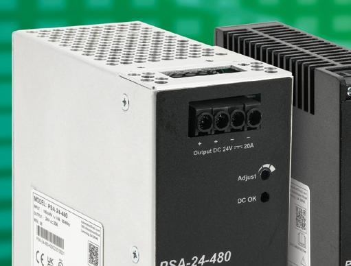
AchieVe PSA series value power supplies offer prices well below the competition and are ideal for price-sensitive users who require basic yet reliable power output for general industrial applications. Their overcurrent protection is designed to operate in constant current mode, making the PSA series suitable for inductive and capacitive loads.
• Universal 85-264 VAC/120-375 VDC input voltage
• 12, 24, or 48 VDC adjustable output options
• 75, 120, 240, and 480 Watt models
• Rugged plastic or aluminum housings

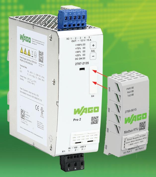


WAGO Pro2 Series DC Power Supplies starting at $185.00
WAGO Pro2 series performance power supplies combine a compact design with intelligent load management to deliver reliable, fail-safe DC power, reducing energy losses, saving cabinet space, and maximizing energy efficiency. The free configuration software includes long-term monitoring for preventative maintenance and service, preventing costly downtime.
• Models with outputs up to 40A/960W
• 120, 220, 240, or 480 VAC input voltage options
• 12, 24, and 48 VDC output options
• Single- and three-phase models
• Free configuration and monitoring software
WAGO Pro2 Communication Modules starting at $71.00
WAGO Pro2 communication modules easily snap into place as an add-on to Pro2 power supplies, allowing connectivity to PLCs for programming and monitoring, providing accessibility to select features and real-time data, and supporting the following protocols:
• Modbus RTU with (2) RS-485 (RJ45) ports
• EtherNet/IP with (2) Ethernet 10/100 Base-T (RJ45) ports
• IO-Link with (1) 3-position removable terminal port
• Modbus TCP/IP and UDP/IP with (2) Ethernet 10/100 Base-T (RJ45) ports Also Available




















Quite a few years ago, I recorded a video for our publication’s YouTube channel entitled, “What is your engineering degree worth?” The video really took off, eventually racking up more than 150,000 views, and it’s still going today. The video delved into the cost of an engineering degree here in the United States, and what some studies were saying about the value of that degree, when multiplied out over a 40-year career.
In polite society, the question, “How much do you make?” isn’t one that’s often heard at dinner parties — nor around the office. But no matter the occupation, people are genuinely interested in what others earn and where they stand in comparison. If only we had more data.
So, I’m happy to announce that for the first time, Engineering.com, along with this publication and several other respected engineering brands, have joined forces to produce a comprehensive salary survey to shine a light on what today’s engineers are earning. Including disciplines such as mechanical, electrical, and aerospace, this inaugural study (covering professionals in the U.S. and Canada) sets the stage for a better understanding of how the industry is evolving — and what engineers value most in their careers.
With data gathered from nearly 600 full-time engineers, our survey reveals more than just basic salary figures. It explores benefits preferences, vacation norms,
job roles, and career trajectories, offering insights into the professional engineering landscape. It also raises important questions about workforce sustainability, with a significant portion of respondents nearing retirement age and relatively few early-career engineers represented.
What do engineers prioritize in compensation packages? How prevalent are bonuses and retirement contributions? What does the average career path look like regarding discipline, job function, and level of responsibility? These are just a few of the issues emerging from this year’s results.
The full report offers data for engineers navigating career choices and for employers looking to attract and retain top technical talent. And best of all, it’s free to access. Visit bit.ly/4mAAVdJ to check it out for yourself. DW


Paul
J. Heney • VP, Editorial Director pheney@wtwhmedia.com
On X (formerly Twitter) @wtwh_paulheney
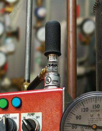
NEMA 12
For large heat loads up to 5,600 Btu/hr.
• Enclosure remains dust-tight and oil-tight
• Measures 8" (203mm) high
• Mounts top, side or bottom
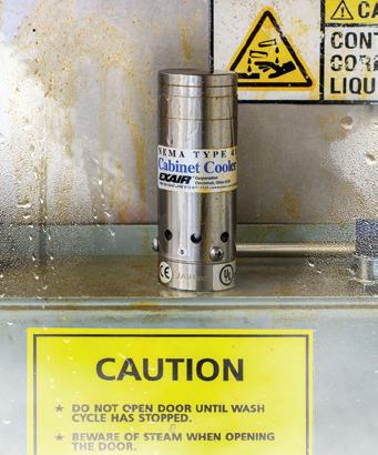
NEMA 4 and 4X
For heat loads up to 5,600 Btu/hr.
• Enclosure remains dust-tight, oil-tight and splash resistant
• Suitable for wet locations where coolant spray or washdown can occur
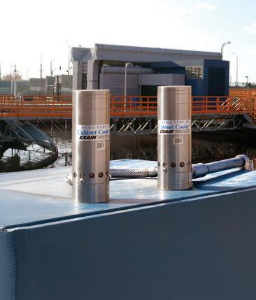
For NEMA 4X applications available for heat loads up to 5,600 Btu/hr.
• Resists harsh environments not suitable for Type 303/304SS
• Ideal for food and chemical processing, pharmaceutical, foundries, heat treating and other corrosive environments
• Less expensive to purchase than refrigerant A/C units

• Less expensive to operate than refrigerant A/C units
• Quicker to install than heat exchangers and refrigerant A/C units
• Little to no maintenance
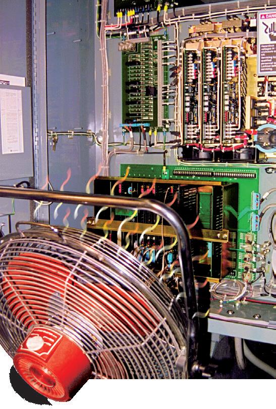

• More reliable in dirty, hot, or remote environments than alternative cooling products
Not affected by machine vibration which can cause
Ambient temperature does not affect performance like it will with alternative cooling products

Hazardous Location and ATEX
For use with classified enclosure purge and pressurization systems. Available for classified environments up to 5,600 Btu/hr.
• Maintain NEMA 4/4X integrity
• For hazardous/explosive environments
• CE compliant
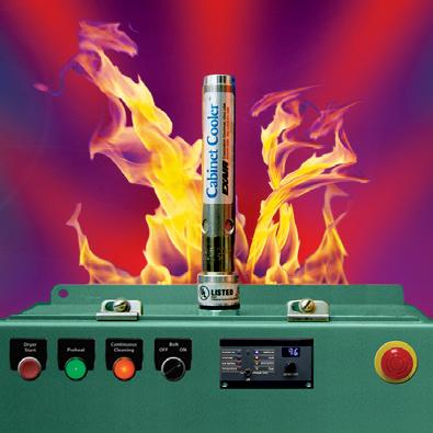
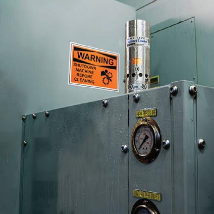
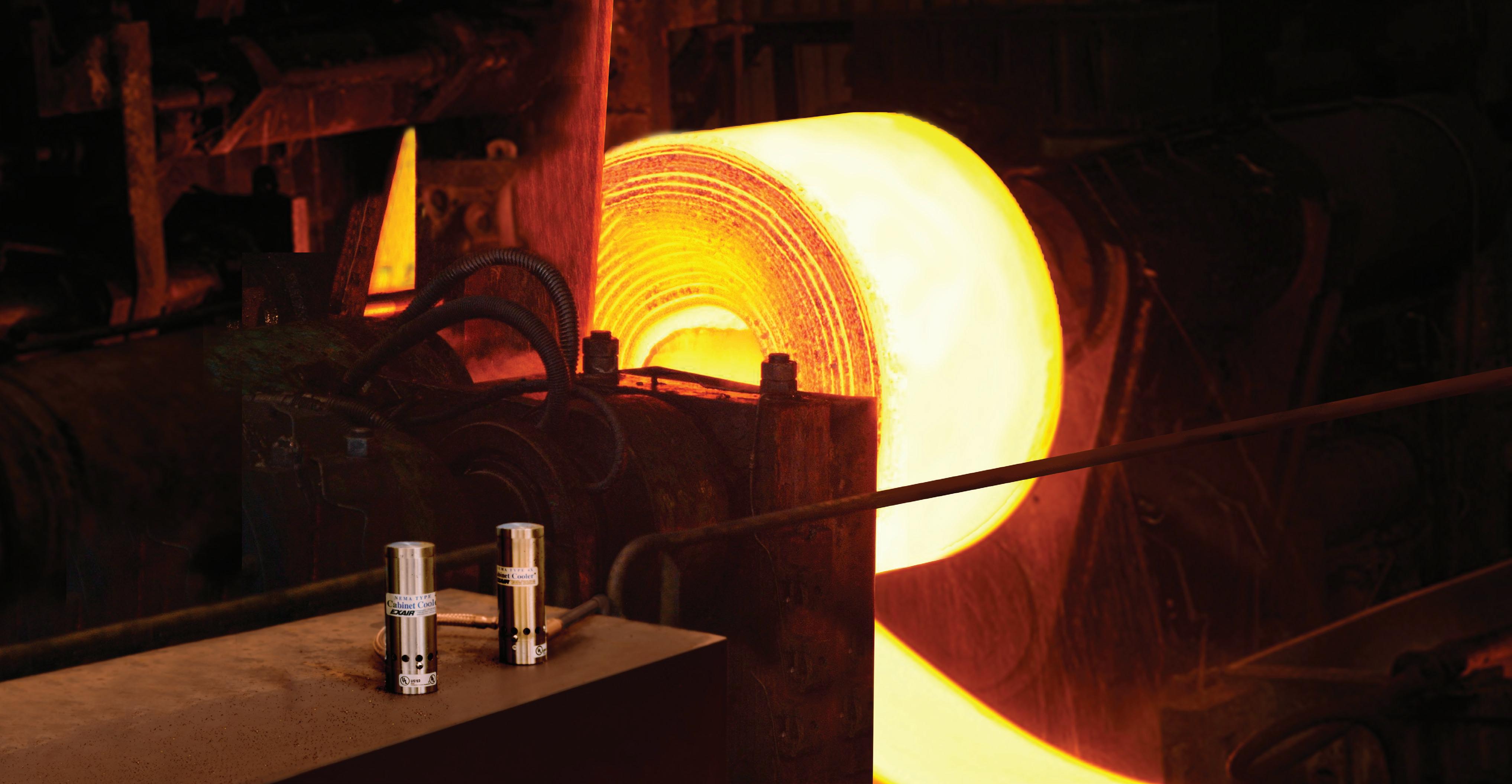
For NEMA 12, 4 and 4X applications. Available for heat loads in many capacities up to 5,600 Btu/hr.
• Suitable for ambients up to 200°F (93°C)
• Ideal for mounting near ovens, furnaces, and other hot locations
Keep a slight positive pressure on the enclosure to keep dirt from entering through small holes or conduits. For use in non-hazardous locations.
• Uses only 1 SCFM in purge mode
• For heat loads up to 5,600 Btu/hr.
• NEMA 12, 4 and 4X
Stop electronic downtime with an EXAIR Cabinet Cooler System! The complete line of low cost Cabinet Cooler Systems are in stock and can ship today. They mount in minutes through an ordinary electrical knockout and have no moving parts to wear out. Thermostat control to minimize compressed air use is available for all models. All Cabinet Coolers are UL Listed, UL Classified and /or CE Compliant.


MOTION CONTROL
Using motion controls in autonomous robotics
A new AMR uses a precision controller-drive to accurately mark construction sites with building details.
LINEAR MOTION
With a few best practices, machine builders can design automation systems that increase equipment availability, performance, and elevate product quality.
Pillars of Production: How engineers
PCBs are the backbone of electronic systems that support every industry and application. Here is how to optimize them.
“Thread galling” occurs during the installation of bolts and nuts where the bolts are twisting off and/or the bolt’s threads are seizing to the nut’s threads.
Imagine staking your trucking fleet, manufacturing floor robots, or irrigation system on the integrity of the polyethylene (PE) tubes linking their components.
Packaging strategies for aircraft components
Matching high-torque applications with the right servo coupling demands careful consideration of several factors, including torque and misalignment capabilities, speed requirements, and spatial constraints.
Matching high-torque applications with the right servo coupling demands careful consideration of several factors.
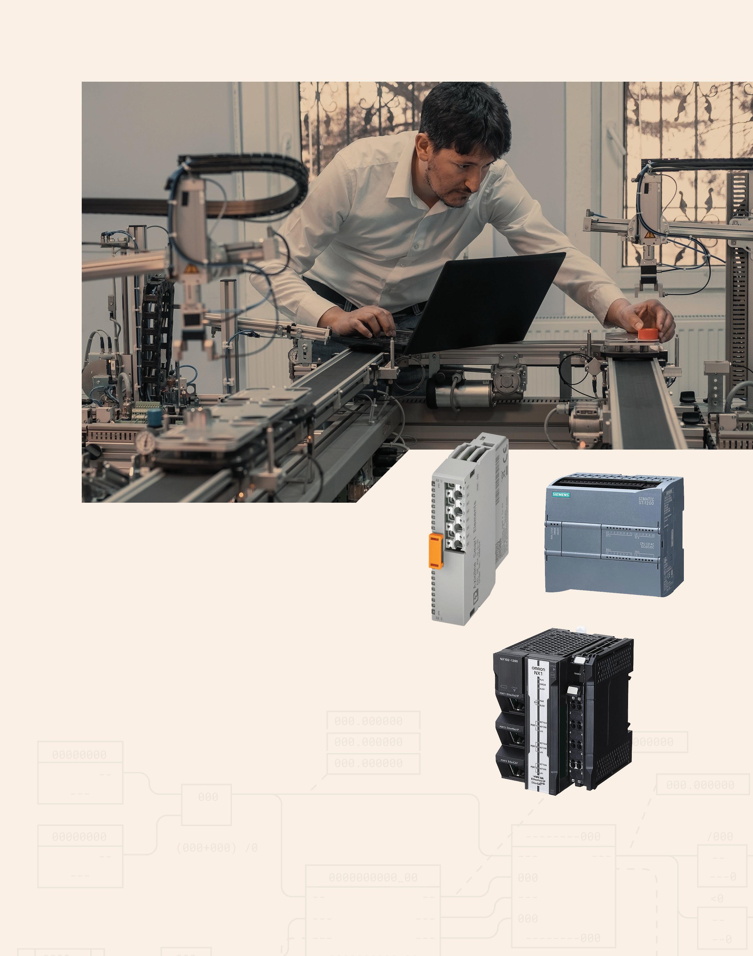
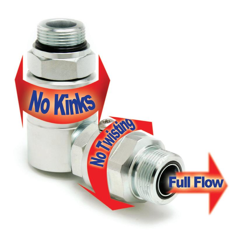
and adapters combine to
and
EDITORIAL
VP, Editorial Director Paul J. Heney pheney@wtwhmedia.com
Editor-in-Chief Rachael Pasini rpasini@wtwhmedia.com
Managing Editor Mike Santora msantora@wtwhmedia.com
Executive Editor Lisa Eitel leitel@wtwhmedia.com
Senior Editor Miles Budimir mbudimir@wtwhmedia.com
Senior Editor Mary Gannon mgannon@wtwhmedia.com
PRINT CREATIVE SERVICES
VP, Creative Director Matthew Claney mclaney@wtwhmedia.com
Art Director Allison Washko awashko@wtwhmedia.com
AUDIENCE DEVELOPMENT
Director, Audience Growth Rick Ellis rellis@wtwhmedia.com
Audience Growth Manager Angel Tanner atanner@wtwhmedia.com
DIGITAL MARKETING
VP, Operations Virginia Goulding vgoulding@wtwhmedia.com
Digital Marketing Manager Taylor Meade tmeade@wtwhmedia.com
PRODUCTION SERVICES
Customer Service Manager Stephanie Hulett shulett@wtwhmedia.com
Customer Service Rep Tracy Powers tpowers@wtwhmedia.com
Customer Service Rep JoAnn Martin jmartin@wtwhmedia.com
Customer Service Rep Renee Massey-Linston renee@wtwhmedia.com
Customer Service Rep Trinidy Longgood tlonggood@wtwhmedia.com
DIGITAL PRODUCTION
Digital Production Manager Reggie Hall rhall@wtwhmedia.com
Digital Production Specialist Nicole Johnson njohnson@wtwhmedia.com
Digital Design Manager Samantha King sking@wtwhmedia.com
Marketing Graphic Designer Hannah Bragg hbragg@wtwhmedia.com
Digital Production Specialist Elise Ondak eondak@wtwhmedia.com
WEB DEVELOPMENT
Web Development Manager B. David Miyares dmiyares@wtwhmedia.com
Senior Digital Media Manager Patrick Curran pcurran@wtwhmedia.com
Front End Developer Melissa Annand mannand@wtwhmedia.com
Software Engineering Manager David Bozentka dbozentka@wtwhmedia.com









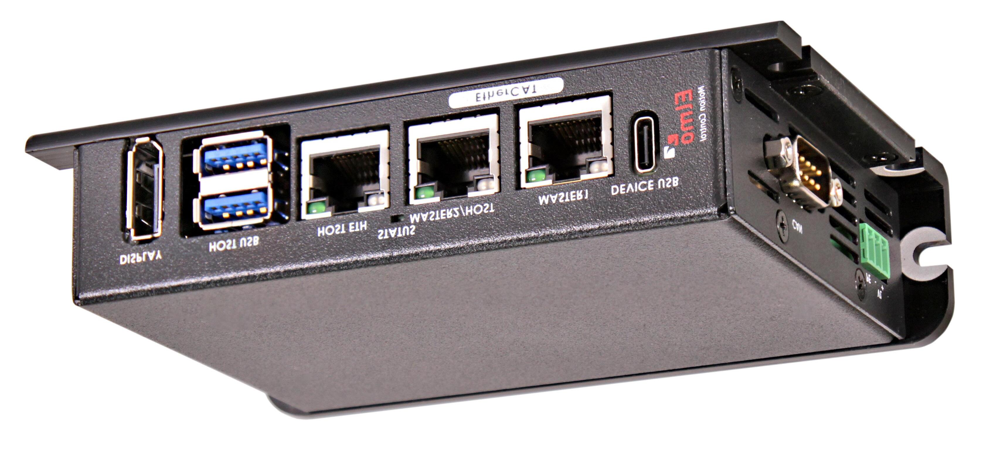
Modern packaging processes are highly automated, fast, and require precise coordination between various machine components. Multi-axis motion controllers ensure these components move together precisely, even at high speeds, to avoid jams, misalignments, or product damage. They can also handle coordinated motion in multiple dimensions.
Elmo Motion Control recently introduced its Titanium Maestro multiaxis motion controller and showcased the product at Automate 2025 in Detroit. It is designed to support complex automation systems such as those in robotics, semiconductor manufacturing, and packaging equipment.
The controller is built around a quad-core 1.9 GHz processor and supports synchronized control of up to 256 motion axes. This high axis count makes it suitable for large or distributed systems where multiple motors must be controlled in coordination. It uses EtherCAT communication, with cycle
times as low as 100 μsec, which helps maintain precise timing and synchronization among connected devices.
From a hardware perspective, the Titanium Maestro is enclosed in a fanless, passively cooled chassis. This design choice reduces the need for maintenance and minimizes contamination risks in sensitive environments. Passive cooling also eliminates moving parts like fans, which can wear out over time.
The controller offers multiple programming options, including support for C++, Python, and graphical development environments. It also includes motion functions such as electronic gearing, CAM profile generation (ECAM), and kinematic transformations for managing systems such as SCARA and delta robots. These features help users configure the controller for a variety of mechanical setups without needing extensive custom programming.
In terms of applications, the Titanium Maestro is used in environments where multiple motors must work together precisely. In robotic systems, it manages coordinated motion between joints and actuators. In semiconductor tools, it can control positioning stages used for wafer handling or inspection. In packaging machinery, it can synchronize conveyors, cutting devices, and actuators involved in labeling and sealing processes.
Elmo also provides development tools and diagnostics to assist with integration and maintenance. These include utilities for simulating motion, adjusting performance parameters, and monitoring system behavior during operation. The intention of these is to reduce setup time and assist in troubleshooting. DW
Elmo
Motion Control www.elmomc.com
Off-highway equipment manufacturers use electric filters in electrified machinery to manage electrical noise, voltage irregularities, or signal integrity, especially in rugged, highinterference environments.
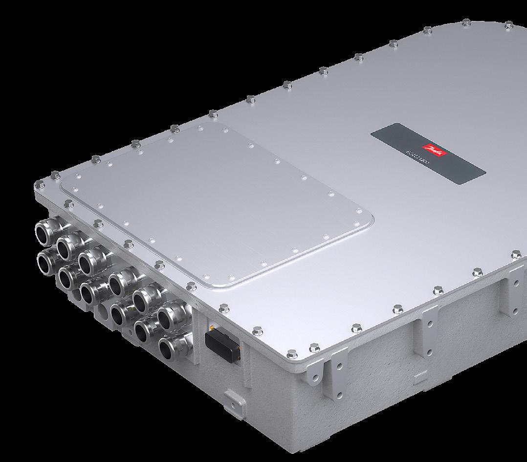
Danfoss Power Solutions launched the Editron ECLCL1200B-350, a heavy-duty LCL electric filter specifically designed for off-highway applications. The LCL1200B electric filter is a compact, mobile-grade solution for fully electric, high-power machinery that pulls power from the ac grid rather than batteries. Applications include drilling equipment, material handling equipment, grid-connected excavators, and other tethered electric machinery.
The filter is designed to be used with the EC-C1200-450-L electric converter. Together, the two components create a grid connection, ensuring compliance with standards. The ECC1200 converts ac power from the grid to provide dc power for the machine, while the filter reduces electromagnetic interference, improving power quality and maintaining system reliability. The combination of components is bidirectional, meaning that it can take power from the grid and feed power back to the grid.
Alternative electric filters are primarily industrial solutions designed for stationary applications, requiring additional measures to provide the same level of protection in harsh conditions. The filter’s compact design also makes it a better fit for mobile machinery, saving space and reducing weight.
The new electric filter can withstand high levels of mechanical vibration and shock, while its ingress protection ratings of IP6K9K and IP67 protect from moisture and dust. Rated for up to 560 Vac and 50/60 Hz, the LCL1200B filter is compatible with European and U.S. three-phase power supplies. All components are rated for 300 ARMS and 250 kVA. The filter is designed for operating altitudes of up to 4,000 m.
Danfoss Power Solutions • www.danfoss.com
WHITTET-HIGGINS manufactures quality oriented, stocks abundantly and delivers quickly the best quality and largest array of adjustable, heavy thrust bearing, and torque load carrying retaining devices for bearing, power transmission and other industrial assemblies; and specialized tools for their careful assembly.
Visit our website–whittet-higgins.com–to peruse the many possibilities to improve your assemblies. Much technical detail delineated as well as 2D and 3D CAD models for engineering assistance. Call your local or a good distributor.
Stick-slip motor stages, also known as inertial piezo stages or slipstick actuators, are precision motion devices that use the stick-slip effect to achieve nanoscale or microscale linear movement. Stick-slip inertia motors operate on a principle similar to the classic tablecloth trick, using piezoelectric actuators driven by a modified sawtooth voltage signal from dedicated control electronics. During the slow expansion phase, the actuator gradually moves a runner forward. When the actuator contracts rapidly — within microseconds — the runner’s inertia prevents it from following, resulting in net forward motion. A symmetrical motor configuration ensures consistent performance in both forward and reverse directions.
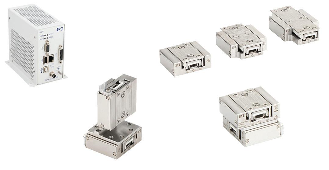
Physik Instrumente (PI) introduced the B-421 BIX nanopositioning stages as compact, high-precision linear positioning systems designed for
reliable, accurate motion in extremely space-constrained environments. Equipped with integrated linear encoders with 6-nm position resolution and dual-phase piezo inertia motors (stick-slip motors), BIX stages are backlash-free with a minimum incremental motion of 0.01 microns per step.
The BIX series uses two miniature piezo stacks, manufactured in-house by PI’s piezo ceramics division, PI Ceramic. The biphase inertia drive technology aims to provide higher drive and holding forces, increased velocity, and extended operational lifetime.
The BIX linear stage design supports multi-axis configurations and travel ranges of up to 32 mm, making these miniature nanopositioning stages suitable for high-precision motion applications, such as bionanotechnology, super-resolution microscopy, metrology, life sciences,
spectroscopy, micro-assembly, photonics, semiconductor manufacturing, and interferometry.
The E-881 BIX piezo motor controller is designed for highperformance control of low-voltage, two-phase stick-slip piezo motors, enabling smooth, precise motion with nanometer resolution. It features integrated encoder feedback and digital servo control electronics and is compatible with PI’s PIMikroMove software. USB and TCP/IP interfaces support communication. Additional features include programmable digital outputs and a built-in data recorder. The controller has an extensive set of drivers for use with C, C++, C#, NI LabVIEW, MATLAB, Python, and a virtual startup emulator for testing without hardware. DW
C o m p a c t D e s i g n I H i g h P r e c i s i o n I I n c r e a s e d P r o d u c t i v i t y


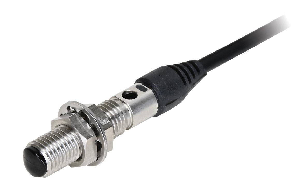
For industrial equipment, the intersecting trends of increasing automation and reduced installation space mean that designers need compact and high-performance technologies for discrete sensing applications. General-purpose sensors simply do not fit, and other technologies such as fiber optic devices are more costly and require separate amplifiers which complicate installation requirements. Even as acceptable form factors shrink, there remains an escalating need for better accuracy, detection distances, and response times.
To meet these needs, IDEC has added the SA1N series of subminiature PE sensors to its product lineup. The SA1N sensors are available in two versions: a barrel-mount fiber-
type diffuse-reflective infrared LED style, secured with M6 nuts through a mounting hole; and a block-type convergent-reflective red LED style, secured with two mounting holes located at a 14-mm pitch
Both versions are all-in-one devices with built-in amplifiers and sensitivity adjustment control. The barrel-mount version has a 3 to 50 mm sensing range, while the block-type can detect over a 5 to 30 mm sensing range. Both models are available in NPN or PNP light-on configurations, and both provide a rapid 0.5 msec maximum response time.
The sensors each come with flexible 2-m pigtail wiring, functioning at standard 24 Vdc with minimal current draw. They operate over a wide -25 to 55° C temperature range. The barrel-
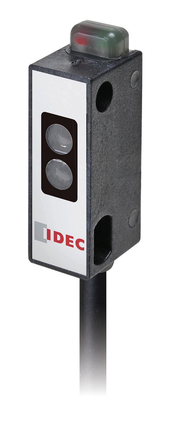
mount version uses a stainless-steel housing and plastic encapsulation to achieve an IP67 rating, while the blocktype is rated at IP64.
Many types of production line equipment and manufacturing machinery in the food and beverage and medical industries require positive presence detection of machine components and product positioning or counting. IDEC’s SA1N series of subminiature PE sensors fit into the limited space available for these types of applications, providing accuracy and performance in compact barrel and block form factors. DW
IDEC • www.us.idec.com







the versatility of our pellet-fed additive manufacturing materials, which can play a key part in new approaches to producing architectural components. We foresee many innovative applications for 3D printing in this space.”
LNP THERMOCOMP compounds can be formulated to meet specific engineering attributes, including strength, stiffness, specific gravity for weight management, or a solid feel, heat and chemical resistance, flow properties, and dimensional stability. DW
SABIC • sabic.com

SABIC collaborated with Branch Technology to develop lightweight panels to restore the exterior of the Pathfinder, an early test article for the National Aeronautics & Space Administration (NASA) space shuttle orbiter. The restored Pathfinder is displayed at the U.S. Space & Rocket Center museum in Huntsville, Ala.

• EDITED BY MIKE SANTORA

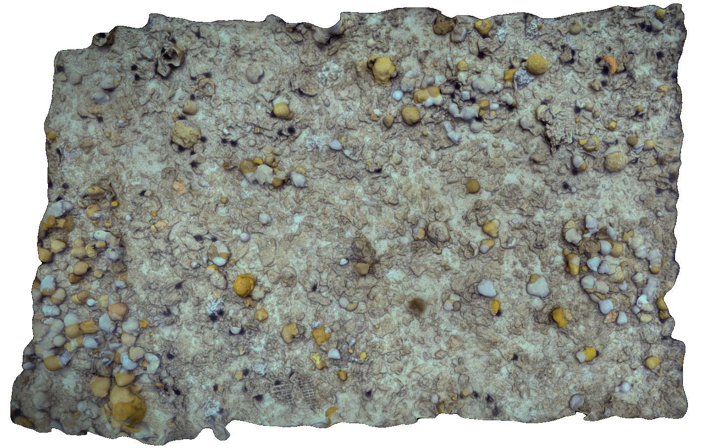
Navigation and autonomous systems company Advanced Navigation recently collaborated with marine consultancy O2 Marine to reveal an explicit visual depiction of Hall Bank — a small, nearshore reef in Southwest Australia (32°S)[1], located well beyond the typical latitudinal range for coral reefs.
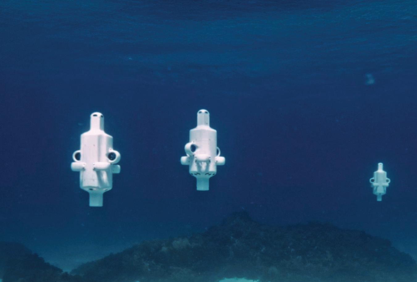
Using Hydrus, a micro hovering autonomous underwater vehicle (AUV), the teams conducted a detailed survey of the reef, capturing geo-referenced high-resolution imagery and 4K video in parallel. The data showed severe coral bleaching and fragmentation, laying bare a hidden yet escalating crisis at one of the world's southernmost reefs.
O2 Marine’s ambition lies in aiding businesses to accelerate efforts in marine environmental assessment
Advanced Navigation’s Hydrus unveils effects of coral bleaching at
and monitoring, marine fauna, and oceanography. This necessitates the use of advanced technology to collect data and insights for knowledge-sharing in a cost-effective way.
“To truly understand the extent of coral bleaching, we need highresolution, spatially accurate data that captures both the scale and the fine detail of change beneath the surface,” said Claudio Del Deo, Co-Managing Director at O2 Marine.
The data gathered from Hydrus was used to generate a 3D digital twin of the Hall Bank seabed. The model revealed a barren seafloor filled with pale, lifeless corals, documenting the shrinking coral formations.
This comes at a time when both of Australia’s two world heritage-listed reefs — Ningaloo and the Great Barrier Reef — were simultaneously hit by coral bleaching in March 2025, driven by an intense marine heatwave that drove sea
surface temperatures up to 4°C above the summer average[2].
“Unlike traditional underwater vehicles, Hydrus’s compact design, fleet deployability, and ability to gather professional grade data, allow us to monitor reefs at a scale and frequency previously unattainable. This level of detail is essential for informing conservation strategies and building the baseline needed for long-term reef recovery,” added Del Deo at O2 Marine.
As we expand our conservation efforts globally, Hydrus is proving to be an indispensable part of our toolkit, enabling actionable insights that will guide both immediate responses and future restoration.”
The Hall Bank site — regarded as a rare and valuable example of highlatitude reef resilience[1] — was an
ideal deployment area for Hydrus. Its ability to support extensive coral cover in cold, turbid waters makes it a vital natural lab for studying climate adaptation. Hosting a unique mix of tropical, subtropical, and temperate coral species, it offers critical insights into species range shifts and reef development under changing ocean conditions[3].
The mission involved the simultaneous deployment of three Hydrus units, each executing coordinated transects and lawnmower survey patterns across different sections of the reef.
This approach enabled comprehensive spatial coverage, ensuring overlapping, high-resolution data capture across the site. By flying precise, parallel tracks, the AUV was able to systematically map the reef’s structure and condition, capturing the fine-scale changes in coral health
that are often missed by traditional survey methods.
Speaking to the mission’s success, Alec McGregor, Senior AI Engineer at Advanced Navigation, said, “Collecting high-quality ocean data has traditionally been slow, costly, and resource-intensive, where sending divers or ROVs below 50 meters in depth can run into tens or even hundreds and thousands of dollars. That simply doesn’t scale, especially when time-sensitive data is needed across large or remote areas.
This AUV changes the equation. At just 15.4 lb, it can be deployed by a single person, without the need for support vessels or complex logistics. This mission is a powerful example of what’s possible when cutting-edge robotics meets urgent environmental challenges. Hydrus puts critical data into the hands of scientists and marine operators faster, more safely,

Our cords are proudly made in America with the finest raw materials and thoroughly tested—no overseas agendas or shipping. And, they come with 1-week U.S. lead times, and same-day shipping on stocked products. In a world where international supply chains are unreliable and pricing changes by the week, isn’t it time for some stability? Scheduled and blanket ordering are available to lock in your price for 1 year while having cords shipped at intervals. Welcome home!
Toll-Free Phone: (800) 662-2290
E-mail: info@interpower.com
Business Hours: 7 a.m.–5 p.m. CST Order Online! www.interpower.com

As a global leader in pump technology, we specialize in providing customized solutions to meet your unique needs.
From design and production to distribution, we deliver high-performance diaphragm pumps and systems for handling both gases and liquids.


Find your perfect pump solution – contact us today!

and more affordably — enabling smarter, more timely decisions for conservation and climate adaptation.”
Continuing to drive the drone revolution underwater
Today, ocean temperatures continue to rise, mass coral bleaching events are becoming more frequent. Yet only 26.1% of the ocean floor has been explored[4].
To unlock the ocean’s mystery and open it up for further scientific discovery, Advanced Navigation is appealing to the goals of the Seabed 2030 initiative[5] and the overarching United Nations “Ocean Decade” development plan[6], by working with partners to map the ocean floor.
This mission builds on Hydrus’s growing track record of underwater discovery and documentation — from coral reefs to shipwrecks. In 2024, Hydrus spotted a 64-meter shipwreck[7] — more than twice the size of a blue whale, the largest marine animal — scattered across the seafloor in the Indian Ocean. Together with Curtin University HIVE, Advanced Navigation was able to rebuild a high-resolution replica of the wreck using the data gathered by Hydrus. The model now sits with the Western Australian Museum’s public archive, and can be seen in life-size form at the Curtin University HIVE on their immersive Cylinder display. DW
Advanced Navigation www.advancednavigation.com
1. Thomson, D.P., & Frisch, A. J. (2010). Extraordinarily high coral cover on a nearshore high-latitude reef in south-west Australia. Coral Reefs, 29, 923-927.
2. Richards, Z. (2025). Synchronised bleaching: Ningaloo and the Great Barrier Reef are bleaching in unison for the first time. The Conversation.
3. Ross, C. L., French, B., Lester, E. K., Wilson, S. K., Day, P. B., Taylor, M. D., & Barrett, N. (2021). Coral Communities on Marginal High-Latitude Reefs in West Australian Marine Parks. Diversity, 13(11), 554.
4. National Oceanic and Atmospheric Administration (2024). How much of the ocean has been explored? NOAA Office of Ocean Exploration and Research.
5. Seabed 2030. Seabed 2030 website.
6. UNESCO. United Nations Decade of Ocean Science for Sustainable Development (2021-2030). UNESCO website.
7. Advanced Navigation (2024). Hydrus Plunges Into Rottnest Ships Graveyard, Investigating Maritime Mysteries. Advanced Navigation website.

Not a big fan of U.S. foreign trade deficits? Do you like American-made quality with FAST shipping without waiting on overseas port strikes or delays? Interpower cords are made in and shipped from the U.S. heartland where traditional values and work ethics still prevail. Interpower cord sets provide the correct amperages and voltages and ready to use out of the box. Cords are tested at every stage of their manufacture. 1-week U.S. lead times, and same-day shipping on stocked products.
Toll-Free Phone: (800) 662-2290
E-mail: info@interpower.com
Business Hours: 7 a.m.–5 p.m. CST Order Online! www.interpower.com ® ®
• EDITED BY MIKE SANTORA
CONTACT Software is testing how Artificial Intelligence (AI) can significantly accelerate the modernization of German waterways. The solution aims to reduce the effort required to search for information by 60%.
Germany’s waterway infrastructure is in considerable need of modernization, as a look at the structure reveals: 80% of the locks are over 50 years old, with 33% even exceeding 100 years of age (as of 2023). At the same time, there is a lack of experts to carry out the urgently needed measures. Another critical issue: those responsible spend a significant amount of time searching for archive information. In the HyProTwin project, CONTACT Software and partners are developing an AI-based solution to relieve their workload and implement projects more efficiently.
Until now, archive data such as construction or maintenance plans for infrastructure buildings had to be painstakingly researched from various
sources. The quality of this information varies greatly, from structured data to partially outdated scanned documents. The search accounts for up to 25% of the total project effort. Together with the German Federal Waterways Engineering and Research Institute (BAW) and the Institute for Numerical Methods and Informatics in Civil Engineering (IIB) at the Technical University of Darmstadt, CONTACT aims to reduce this figure to less than 10%.
The partners are developing a hybrid AI approach to interpret archive data and make it searchable. It combines symbolic AI, which works with established rules and logical structures, and subsymbolic AI, which learns patterns from large amounts of data. CONTACT’s CIM Database PLM serves as the project’s data backbone, as it is already successfully used for data and process management by the German Federal Waterways and Shipping Administration (WSV). The AI models are directly integrated into the platform.
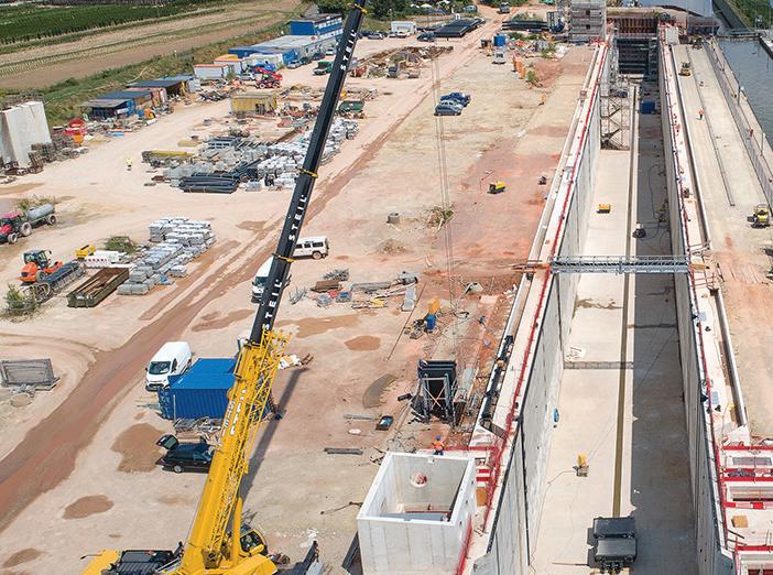
Germany’s waterway infrastructure is in considerable need of modernization, as a look at the structure reveals: 80% of the locks are over 50 years old, with 33% even exceeding 100 years of age (as of 2023).
HyProTwin automatically consolidates the scattered information into digital twins of the buildings. This enables users to quickly find all relevant documents with a single search query, make informed decisions, and optimize planning – for example, regarding environmental emissions. By rating the search results, they also continuously train the AI models.
Although HyProTwin focuses on waterway structures, it also offers potential for other infrastructure areas. “The approach can also significantly accelerate projects in domains such as road or rail transport,” said Christoph Funk, Senior Consultant at CONTACT Software. The three-year project is funded by the German Federal Ministry of Transport (BMV). DW
CONTACT Software contact-software.com
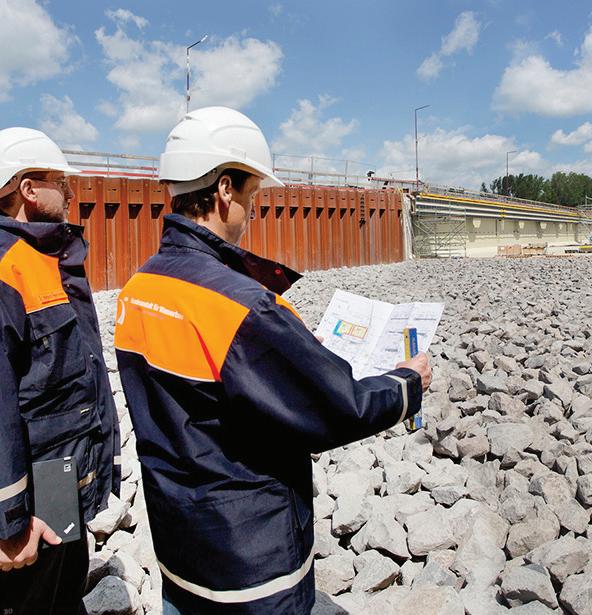
For infrastructure projects, archive data such as building and maintenance plans are essential, yet often time-consuming to find.
Bundesanstalt für Wasserbau
EDITED BY MIKE SANTORA
3D Systems recently announced that the Company is collaborating with researchers from Penn State University and Arizona State University on two projects sponsored by NASA. The projects are intended to enable alternatives to current thermal management solutions. Severe temperature fluctuations in space can damage sensitive spacecraft components, resulting in mission failure. By combining applications expertise with 3D Systems’ additive manufacturing solutions comprising Direct Metal Printing (DMP) technology, tailored materials, and Oqton’s 3DXpert software, the teams are engineering sophisticated thermal management solutions for the demands of next-generation satellites and space exploration.
The project, led by researchers with Penn State University, Arizona State University, and the NASA Glenn Research Center1 in collaboration with 3D Systems’ Application Innovation Group (AIG) has resulted in processes to build embedded hightemperature passive heat pipes in heat rejection radiators that are additively manufactured in titanium. These heat pipe radiators are 50% lighter per area with increased operating temperatures compared with current state-of-theart radiators, allowing them to radiate heat more efficiently for high power systems. Additionally, a project led by researchers at Penn State University and NASA Glenn Research Center2 with 3D Systems’ AIG yielded a process to additively manufacture one of the first functional parts using nickel titanium (nitinol) shape memory alloys that can be passively actuated and deployed when heated. This passive shape memory alloy (SMA) radiator is projected
to yield a deployed-to-stowed area ratio that is 6× larger than currently available solutions, enabling future highpower communications and science missions in restricted CubeSat volume. When deployed on spacecraft, such as satellites, these radiators can raise operating power levels and reduce thermal stress on sensitive components, preventing failures and prolonging satellite lifespan.
Traditionally, heat pipes have been manufactured with complex processes to form porous internal wick structures
that passively circulate fluid for efficient heat transfer. Using Oqton’s 3DXpert software, the Penn State/Arizona State/ NASA Glenn/3D Systems project team embedded an integral porous network within the walls of the heat pipes, avoiding subsequent manufacturing steps and resulting variability. Monolithic heat pipe radiators were manufactured in titanium and nitinol on 3D Systems’ DMP technology. The titanium-water heat pipe radiator prototypes were successfully operated at temperatures of 230°C and weigh 50% less (3 kg/m2
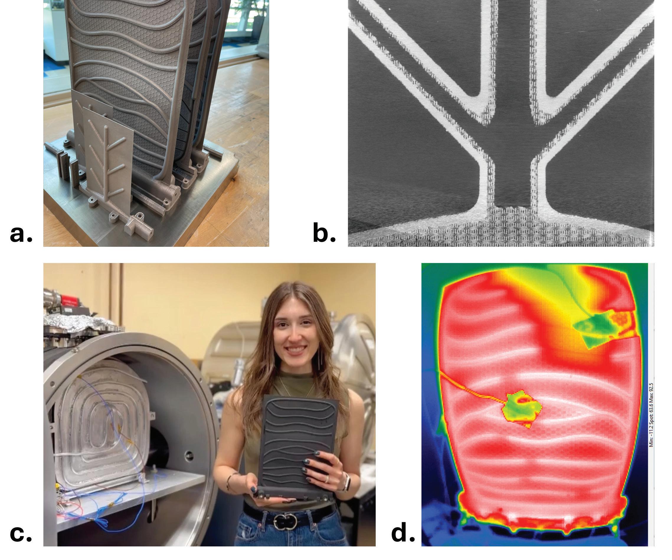
FIGURE 1: a. Additively manufactured high-temperature titanium thermal radiator prototypes with embedded branching heat pipe networks (75×125 and 200×260 mm panels); b. X-ray CT scan of radiator, showing internal porous wicking layer for passive fluid circulation.; c. Penn State University PhD candidate, Tatiana El Dannaoui, installing radiator prototype in thermal vacuum test facility to simulate space environment operation.; d. Thermal image of heat-pipe radiator operating in vacuum chamber. Penn State University
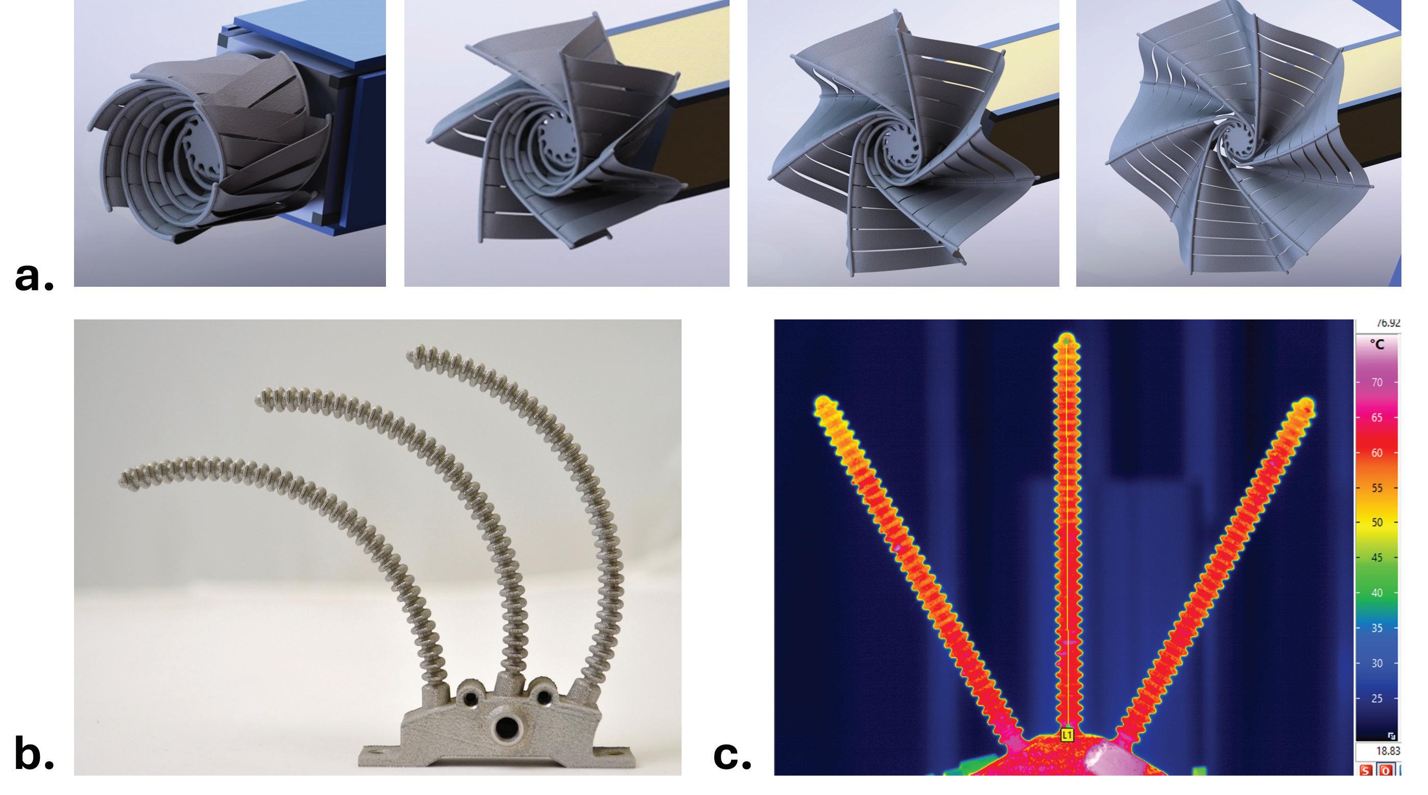
FIGURE 2: a. Concept for additively manufactured shape-memory-alloy (SMA) radiator with radial heat pipe branches deploying from compact stowed form.; b. Prototype SMA demonstrator with highly compliant bellows heat pipe arms.; c. Thermal image of SMA branching bellows heat pipe, showing nearly isothermal operation. Penn State University
versus over 6 kg/m2), meeting NASA goals for heat transfer efficiency and reduced cost to launch for space-based applications.
The Penn State/NASA Glenn/3D Systems team is also pushing the boundaries of what is possible with metal AM by developing a process to 3D print passively deployed radiators with shape memory alloys. The chemistry of these materials can be tuned to change shape with application of heat. SMAs can withstand repeated deformation cycles without fatigue and exhibit excellent stress recovery. The team again used 3DXpert to design the deployable spoke structure of the radiator. This was then 3D printed in nitinol (NiTi), a nickel-titanium shape memory alloy, using 3D Systems’ DMP technology. When affixed to a spacecraft such as a satellite, this device can be passively actuated and deployed when heated by fluid inside, thus removing the need for motors or other conventional actuation in space. The passive shape
memory alloy radiator developed by the team offers transformative advances with projected deployed-to-stowed area ratio that is 6× larger than what is currently considered state-of-the-art (12× versus 2×) and 70% lighter (<6 kg/m2 versus 19 kg/m2).
“Our long-standing R&D partnership with 3D Systems has enabled pioneering research for the use of 3D printing for aerospace applications,” said Alex Rattner, associate professor, The Pennsylvania State University. “The collective expertise in both aerospace engineering and additive manufacturing is allowing us to explore advanced design strategies that are pushing the boundaries of what is considered state-of-the-art. When we complement this with the software capabilities of 3DXpert as well as the low oxygen environment in 3D Systems’ DMP platform, we can produce novel parts in exotic materials that enable dramatically improved performance.”
According to Research and Markets3, the global market for additive
manufacturing in the aerospace industry was estimated at $1.2 billion in 2023 and is projected to reach $3.8 billion by 2030. Additive manufacturing is making a significant impact by enabling the production of airworthy parts with reduced weight and improved performance. In the last decade alone, 3D Systems has worked alongside aerospace industry leaders to produce more than 2,000 structural titanium or aluminum alloy components for space flight, and over 200 critical passive RF flight parts. There are currently more than 15 satellites in orbit with 3D Systems-produced flight hardware on board. DW
3D Systems • 3dsystems.com
1 NASA STMD 80NSSC22K0260 (https://tfaws.nasa.gov/wp-content/uploads/ TFAWS2024-PT-3.pdf)
2 NASA 80NSSC23M0234 • (https://govtribe.com/ award/federal-contract-award/cooperativeagreement-80nssc23m0234)
3 Revolutionizing Aerospace: How Additive Manufacturing is Set to Transform the Industry by 2030 (January 2025).





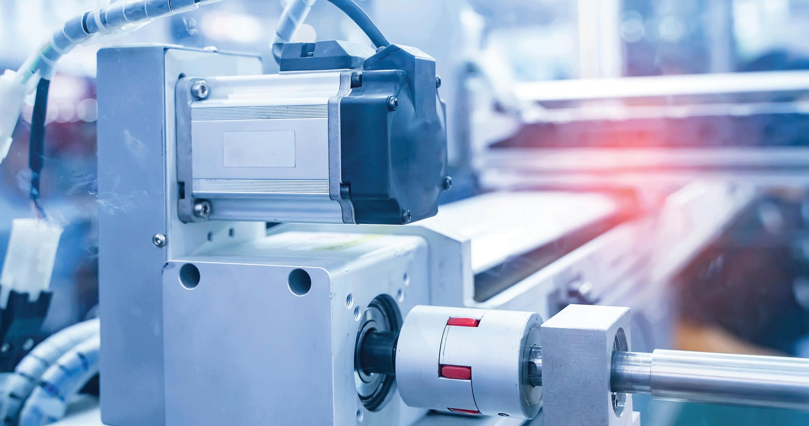

















The construction industry is under pressure. Labor shortages, rising material costs, and the demand for speed and precision are pushing builders to seek automated solutions that boost efficiency, safety, and sustainability.
In most cases, plans are marked in physical spaces using old-fashioned means: Depending on the site, personnel might use a total station (a surveying instrument integrating several measurement tools) or perhaps just tape measures and chalk lines to mark where things go. The approach largely unchanged from those used centuries ago. Huge stacks of blueprint hard copies detailing each floor and system are slowly yielding to digital communications, but information is still manually communicated onsite, explained Dusty Robotics principal engineer Mike Thompson. So too often, a building’s 3D model isn’t what gets built. As various trades lay out their plans, mistakes and outdated information often lead to incorrect layouts, rework, and delays.
So, California startup Dusty Robotics designed an autonomous mobile robot (AMR) called the FieldPrinter 2 to independently map and mark 3D building designs onto 2D construction building floors with 0.0625-in. accuracy. With it, construction teams no longer have to constantly check their laptops, iPads, and paper plans to know what must be built and where.
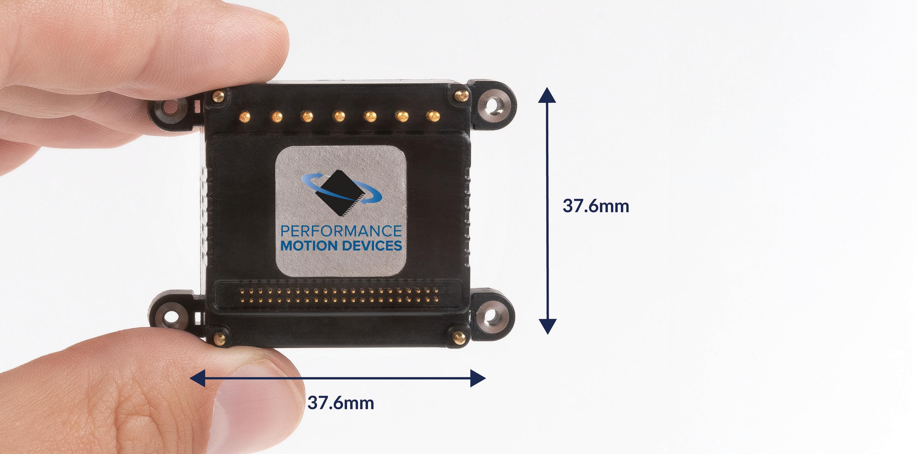
Core to the AMR’s function are two off-the-shelf motion controller-drives from Performance Motion Devices — ION/CME N-series components — that provide control and power for the AMR’s two front wheels … more specifically, the two BLDC motors driving the wheels. The AMR’s rear wheel has no active drive.
Together with a suite of onboard sensors that provide precise location information (including trackers, encoders, and inertial measurement unit gyroscopes) the controller-drives position the robot. “We want continuous motion between all the objects that we print,” said Ryan Dimick, controls
engineer for Dusty Robotics. The system must allow for constant profile changes as the robot switches between navigating and printing.”
In fact, the new FieldPrinter 2 AMR improves on a previous iteration with the help of the PMD controller-drives. The first iteration’s use of another vendor’s motion controllers created challenges for Dusty’s developers, including an inability to understand and rectify errors sans workarounds. The new controller-drive solution addresses these issues and fits into the existing platform.
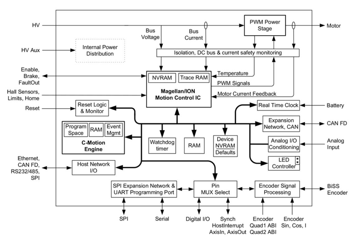
More specifically, the PCB-mountable single-axis controller imparts highperformance motion control, network connectivity, and amplification for an all-inone drive with a built-in processor. So, the robot can download and run code. Plus, the controller-drives give Dusty Robotics visibility and customizability. “When we ran into an issue, it was always something we could fix,” Dimick said. “We overcame any latencies we had in the past and really set our own timing characteristics for the motors and motor control.” For example, Dusty wanted to be able to modify the control loop and field-oriented control loop parameters, Dimick added.
“[Dimick] is constantly pulling data into spreadsheets, graphing it, and looking at
all the inputs and outputs to the motor controller — and understanding what small tweaks we need,” Thompson explained. “That ability to bring graphs into alignment with his expectations — that was a big challenge before.”
Dimick added, “We’re working on a millisecond-level time scale. Getting information very quickly is important for
Powered by a drive and controls from Performance Motion Devices, Dusty Robotics’ AMR maps buildings designs for construction. Shown here is the ION/CME N-series motion-control drive that imparts the Dusty design with the control needed for precision automated operation. The N-Series is a compact, PCB-mountable single-axis controller that provides highperformance motion control, network connectivity, and amplification (delivering up to 1 kW of power) from a tiny 37.6 x 37.6 x 16.8 mm footprint. In fact, this is smaller than a Gen 1 AirPods case for — yet delivers unmatched function and power. The drive’s power and computing density were key reasons it was applied in the space-limited robot design.
all the tuning and high-level controls, and we were not able to reach that prior to PMD.”
Dusty Robotics closely collaborated with the controller-drive supplier to resolve challenges. “Anytime I was integrating the controller into the product and had questions, they were quick to jump on a call, and they even
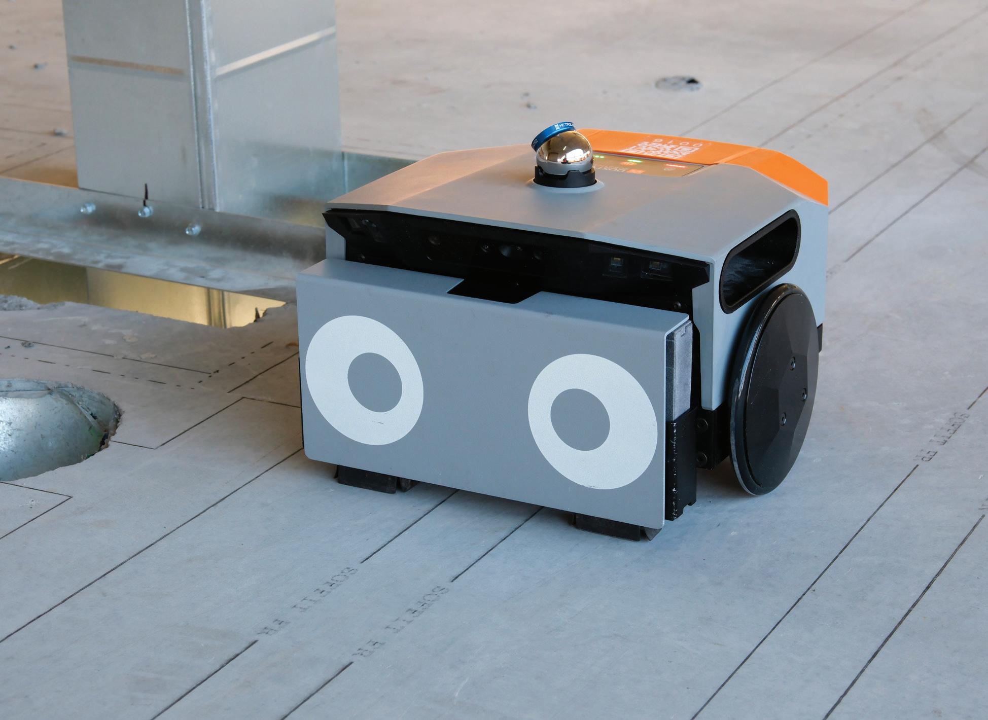
PMD’s ION/CME N-series motion control drive is instrumental to the robot’s position accuracy. PMD’s N-series drives also give the engineers essential insight and access to internal control parameters to customize and troubleshoot the design.

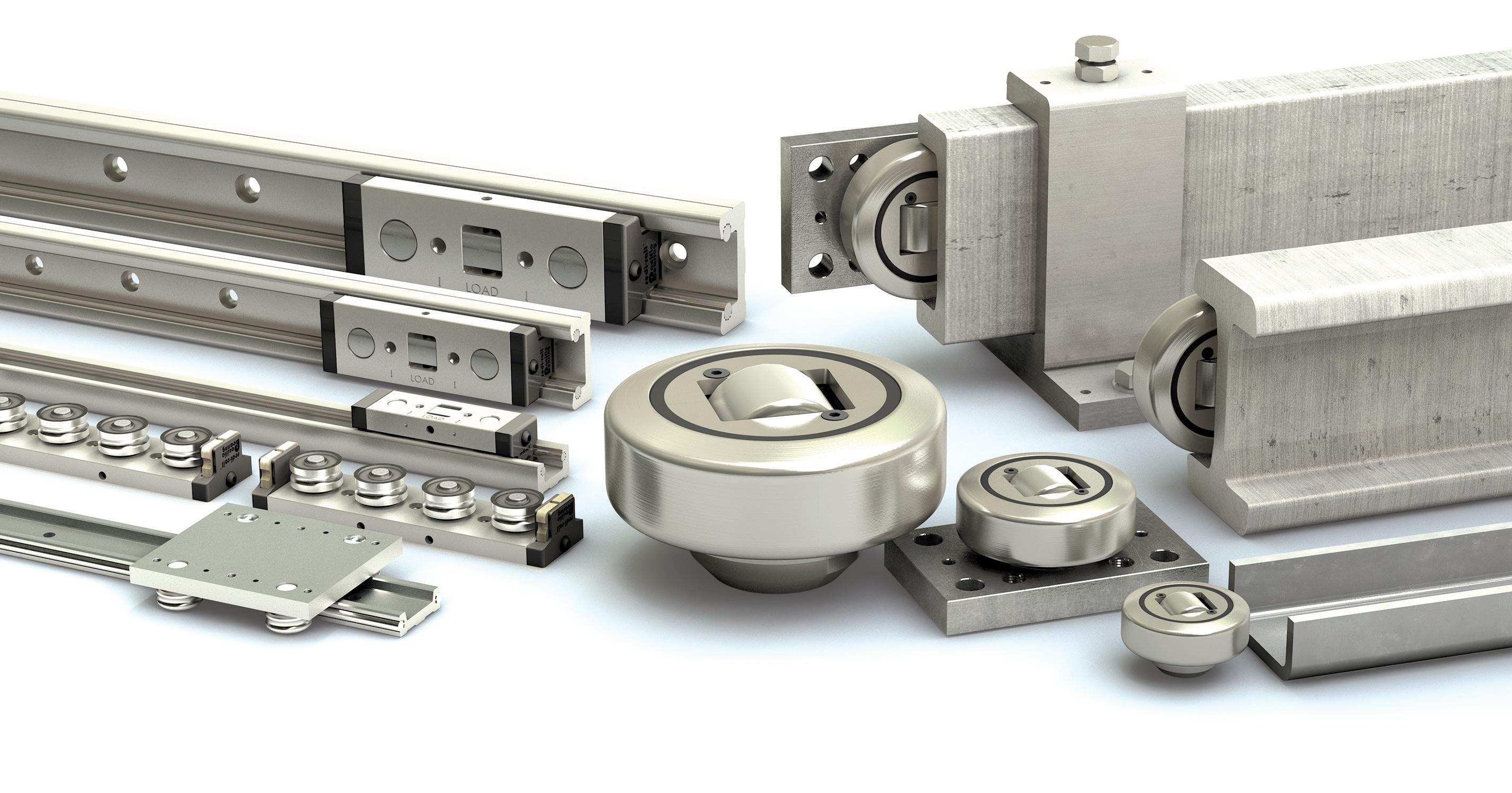
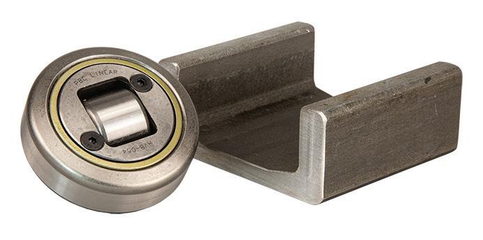
Precision aluminum rails with hardened steel races ensure a lightweight design without sacrificing strength. Gothic arch rollers with sealed double-row ball bearings provide high load capacity and reliable operation in contaminated environments. The carriages come standard with 3-rollers or can be upgraded to a 4-roller or 5-roller carriage. Patented preload adjustment allows for adjustments without the need for disassembly.
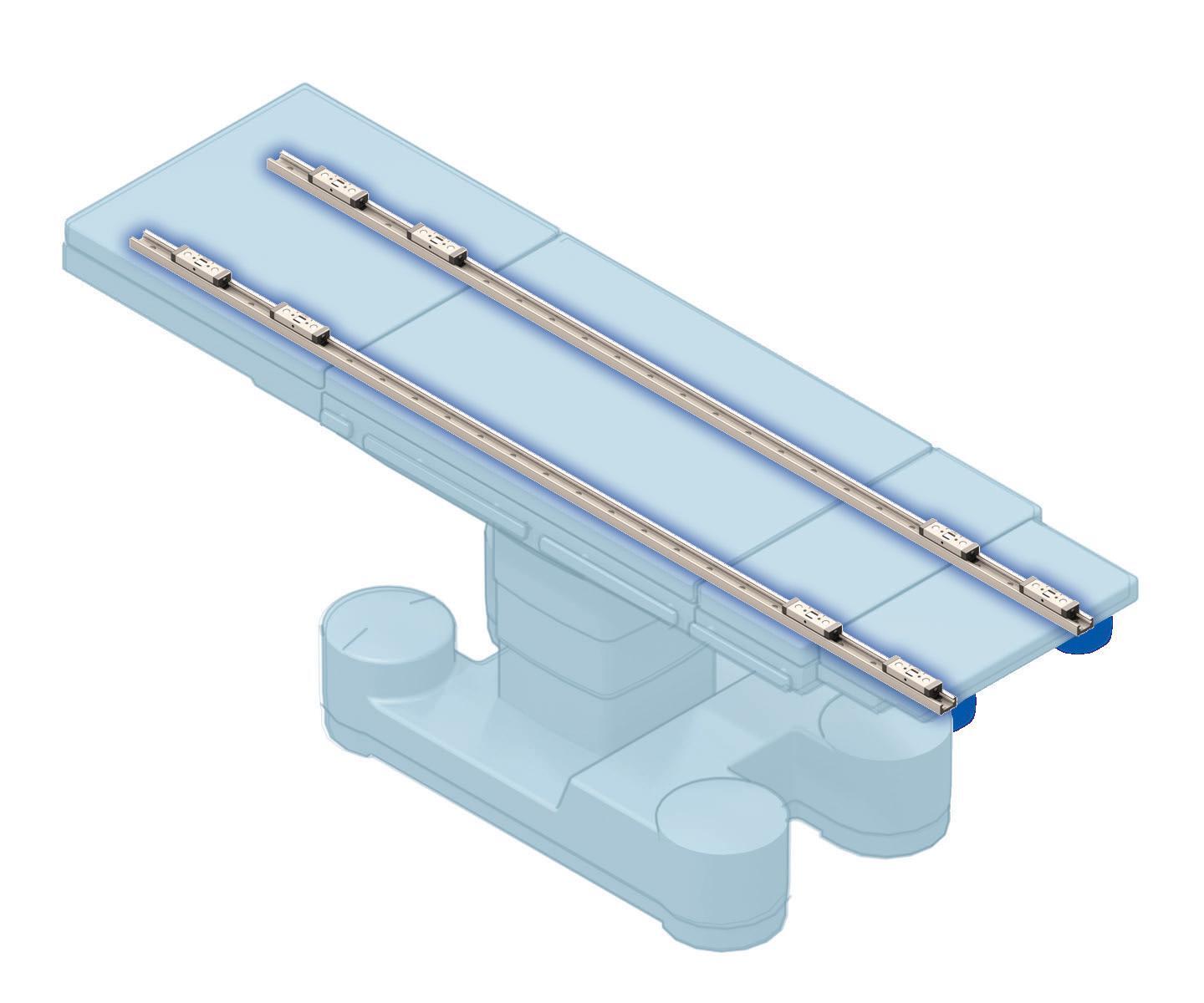

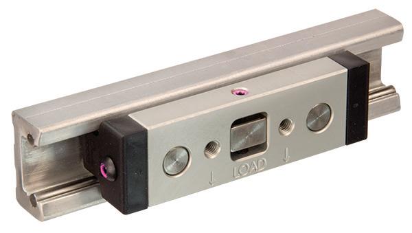
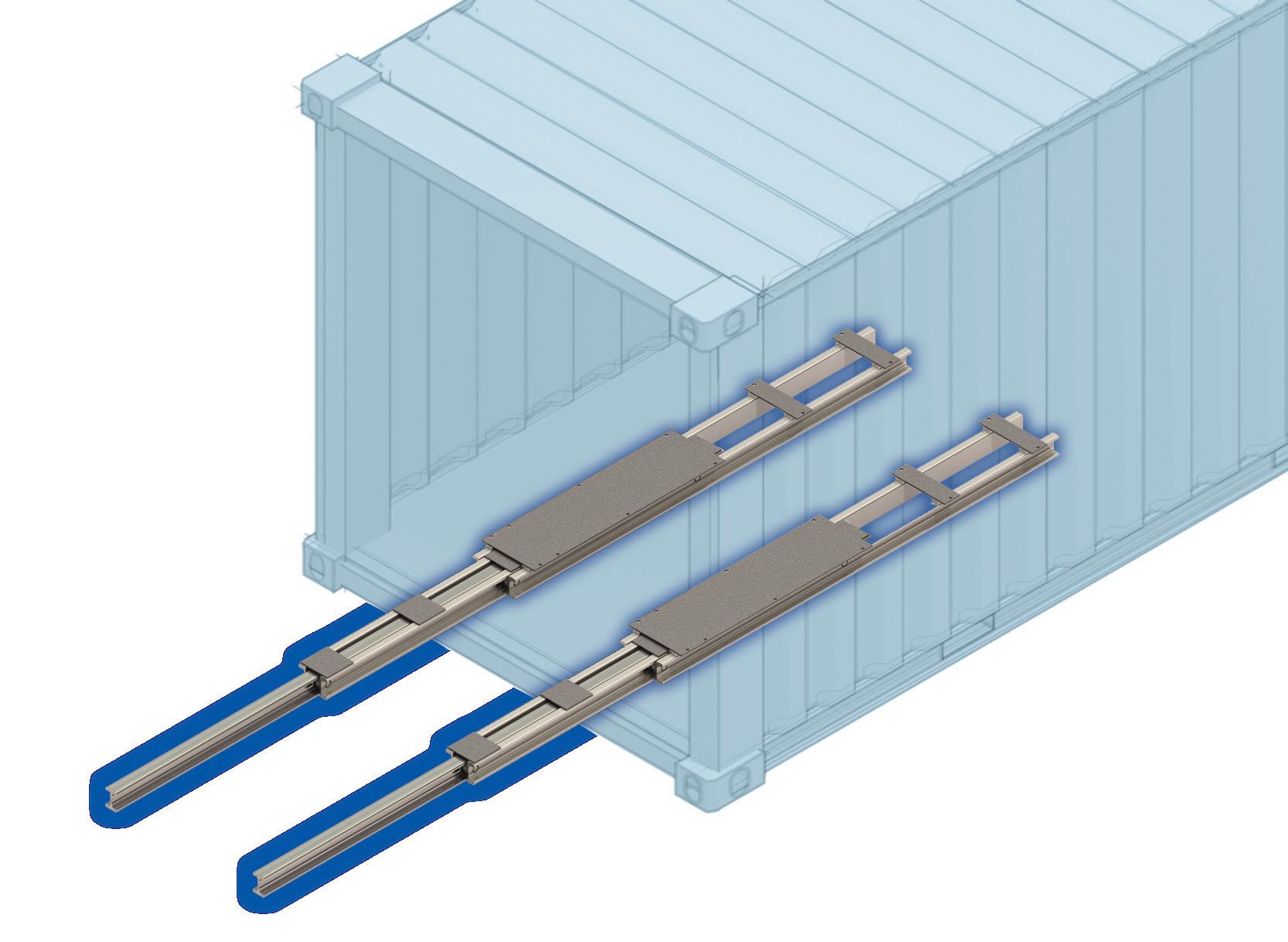
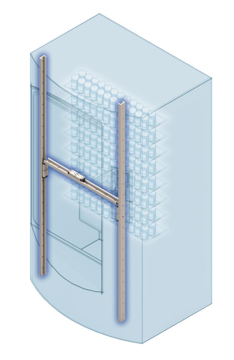
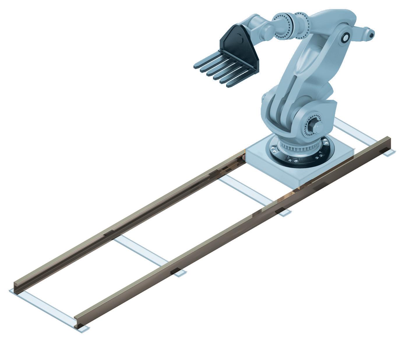
Built for extreme high-load capacities and industrial strength handling, the Hevi-Rail system is easy to mount, align and use. High radial and axial load capacities ensure a long and productive life under continuous use. Available in a range of sizes from the smallest 52.5 mm diameter HVB-053 bearing to the largest 149 mm diameter HVB-063 bearing making the Hevi-Rail a perfect solution for heavy load and lift applications.
released a custom debug version for me to temporarily use for diagnosing an issue,” said Dimick. This collaboration also informed the AMR manufacturer’s industrial-communication choice. The controller-drive supports communication via Ethernet, CAN, RS-232, RS-485, and serial peripheral interface. Dusty wanted certain communications coming in a slightly later version of the controllerdrive. “So, we waited, and I think we were one of the first to really use it. Then we helped [the supplier] debug the firmware, and they quickly returned new versions for us to use.”
The Dusty FieldPrinter 2 has a laser tracker that continuously reports AMR position — but often the tracker doesn’t have a view of the robot, so operation is blind. But the controller-drive (in conjunction with the robot’s sensors) keeps the AMR on track.
“When the robot is printing within a blind spot, not visible to the tracker, it’s relying on the inertial measurement unit and encoders that are coming through the controller. It’s relying on all the
other sensors for five, 10, 15 seconds of continuous printing,” Thompson explained. “Then, when it comes out of the blind spot, it tells the tracker exactly where it is. We need to give that tracker the accuracy so it can very quickly and precisely acquire the signal.”
Here, sub-millisecond timing precision helps the AMR handle blind spots so common at cluttered jobsites. “That information and smooth predictable motion lets the AMR accurately estimate its location and continue printing without line-of-sight to the laser tracker,” said Dimick. This blind-spot printing is the biggest improvement of the new AMR version.
The controller-drive can also apply an electronic brake to the AMR’s motors. A bit of Dusty’s own software, running on one of the controller’s chips, serves as a watchdog. If it loses communication to the robot, it powers down the motors.
As the company name implies, Dusty’s AMR must operate in dirty environments and in all kinds of weather — in the Arizona sun and the
14th floor of a Chicago building under construction when it’s -20° F … and with unknown obstacles and spotty internet connectivity. Unlike competing solutions that leave sensitive electronics exposed, the controller-drive used in the FieldPrinter 2 comes standard with an enclosed package to protect internal components.
Future iterations of the robot could see higher levels of integration. “PMD provides a pathway for us,” Thompson said. They provide the controllers themselves and can open their controllers and give us access to the independent parts to let us create a highly integrated solution, he added. “It’s something that we haven’t really pursued but lets us preserve the investment that the engineers have made … and still make the system faster and lighter than it is today.” DW
Water-resistant Sorbothane provides reliable shock and vibration protection in wet or high-humidity environments.
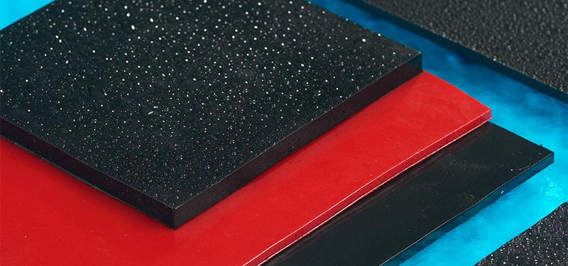
What was initially developed as an insole to improve running shoes has become a critical material in engineering design. Sorbothane, a viscoelastic polyurethane, is now widely used to manage shock, vibration, and acoustic disturbances across various industries, including aerospace, transportation, electronics, medical devices, and many others.
“Sorbothane behaves like a fluid under load but retains enough elasticity to return to its original shape,” explains David Church, president of Sorbothane, Inc. “This duality allows it to dampen energy across multiple axes, unlike foams or rubbers, which tend to function in only one direction or break down over time.”
Foams, being cellular, often degrade with use. Gels, on the other hand, are typically stiffer and less forgiving under impact.
Compared to synthetic rubbers, Sorbothane offers broader flexibility, especially in multi-axis applications. Its dense composition means it doesn't suffer the same structural fatigue, making it particularly well-suited to long-term vibration isolation.
Creep resistance, or a material’s ability to maintain form under prolonged pressure, remains a critical feature. “We test Sorbothane specimens under a weight for two hours,” shares Church. “If the material continues to deform after that, it’s considered to be creeping. Ours stops, holding its shape, which is key to long-term durability.”
Of course, not all design challenges are static. Environmental conditions play a significant role.
“Temperature, humidity, and exposure to water can all influence performance,” says Church. “We engineered a water-resistant variant about 10 years ago specifically for highhumidity or washdown applications. UV exposure isn’t a problem, but degassing can be a factor in some aerospace uses.”
For applications where off-gassing is a concern, the company recommends evaluating material sensitivity early in the design process and reaching out for guidance if needed.
For high-frequency vibration, Sorbothane offers an effective damping solution. “Shape factor is everything,” says Church. “When dialed in correctly, you can achieve up to 95% isolation. Higher frequencies are easier to address. It's the low frequencies that challenge every designer — and in those cases, more weight helps.”
To support fine-tuning, the company provides several free Online Design Calculators on its website. These tools help determine ideal geometries and durometers for vibration, shock, or load conditions.
“We see around 500 users a month,” shares Church. “Our own engineers use them constantly. You can run scenarios for discs, washers, squares, and even strips, to see how they’ll perform in realworld applications.”
That focus on practical solutions extends to prototyping. For thinner parts, Sorbothane is often die-cut from sheet stock. For more complex geometries, engineers can send in aluminum or even 3D-printed molds for casting.
“We’re always working to expand what’s possible,” says Church. “Over the last few years, we’ve developed venting systems that allow for more intricate mold designs, with some that nearly mimic injection molding, despite being a cast material.”
One of the more recent requests? A non-tacky version. “Sorbothane is naturally tacky, which helps in some applications but hinders in others,” he says. “We can coat it to make it non-tacky, but we’re exploring a way to achieve that directly from the mold without adding cost.”
The company is also collaborating with a local university to develop finite element analysis (FEA) models of the material, with the goal of giving design engineers better tools for predicting Sorbothane’s behavior in simulations.
From wearable tech to isolating satellite batteries, Sorbothane continues to prove adaptable. “Sharp corners and thin walls still present challenges,” notes Church. “But if we’re brought in early during the design stage, we can help overcome those with guidance on geometry and wall thickness.”
For engineers unsure where to start, Church offers a simple reminder: “Most people come to us after trying other materials that didn’t work. We encourage them to come to us first. We’re here to help, and more often than not, we can solve the issue.” DW

By following a few best practices, machine builders can design automation systems that increase equipment availability, achieve new levels of performance, and elevate product quality.
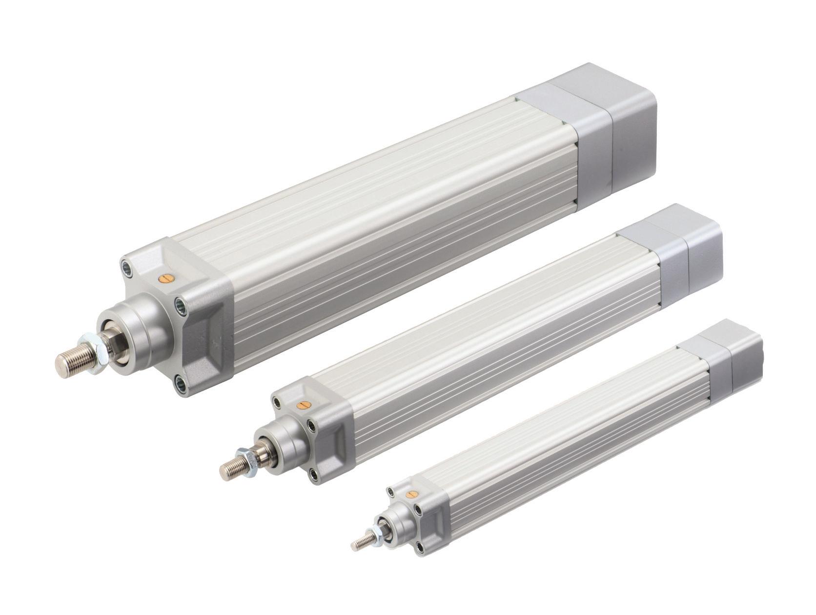
AVENTICS Series SPRA electric rod-style linear actuators offer enhanced load capacity, accuracy, and reliability that helps to maximize productivity.

As more manufacturers digitally transform and automate their production lines, they are gaining a clearer picture of their operations and machine health. And those that connect their assets to powerful software platforms are also gaining the ability to better track key performance indicators (KPIs) such as overall equipment effectiveness (OEE).
OEE measures the efficiency and effectiveness of a production process. Expressed as a percentage, it’s calculated based on three factors: availability, performance, and quality. The OEE values of today's manufacturers can fall within a wide range, with 40% and under considered below average and 85% and higher considered above average. The higher the value, the more efficient and productive a company is.
To help manufacturers raise their OEE values, it's critical that automation system designers create systems that are as reliable, fast, and accurate as possible. Given their many benefits, there’s little surprise that designers


are increasingly incorporating electric linear actuators to achieve high-throughput, high-precision automation.
Electric linear actuators provide fast and accurate movement of materials and products in a versatile system that can easily scale to meet changing demands. With continued technology advancements, these actuators can meet challenging performance requirements, offering heavy payload capacities, precise repeatability, and high speeds.
Choosing an optimal system for a specific application requires a deep understanding of the options available. Manufacturers of electric linear actuators offer a wide range of models for both single-axis and multi-axis applications. These actuators use a range of designs and motion components to serve different load, accuracy, and speed characteristics.
To navigate the many options available and find the most effective electric linear actuator for optimizing OEE, motion system designers and engineers can leverage several strategies to streamline the process.

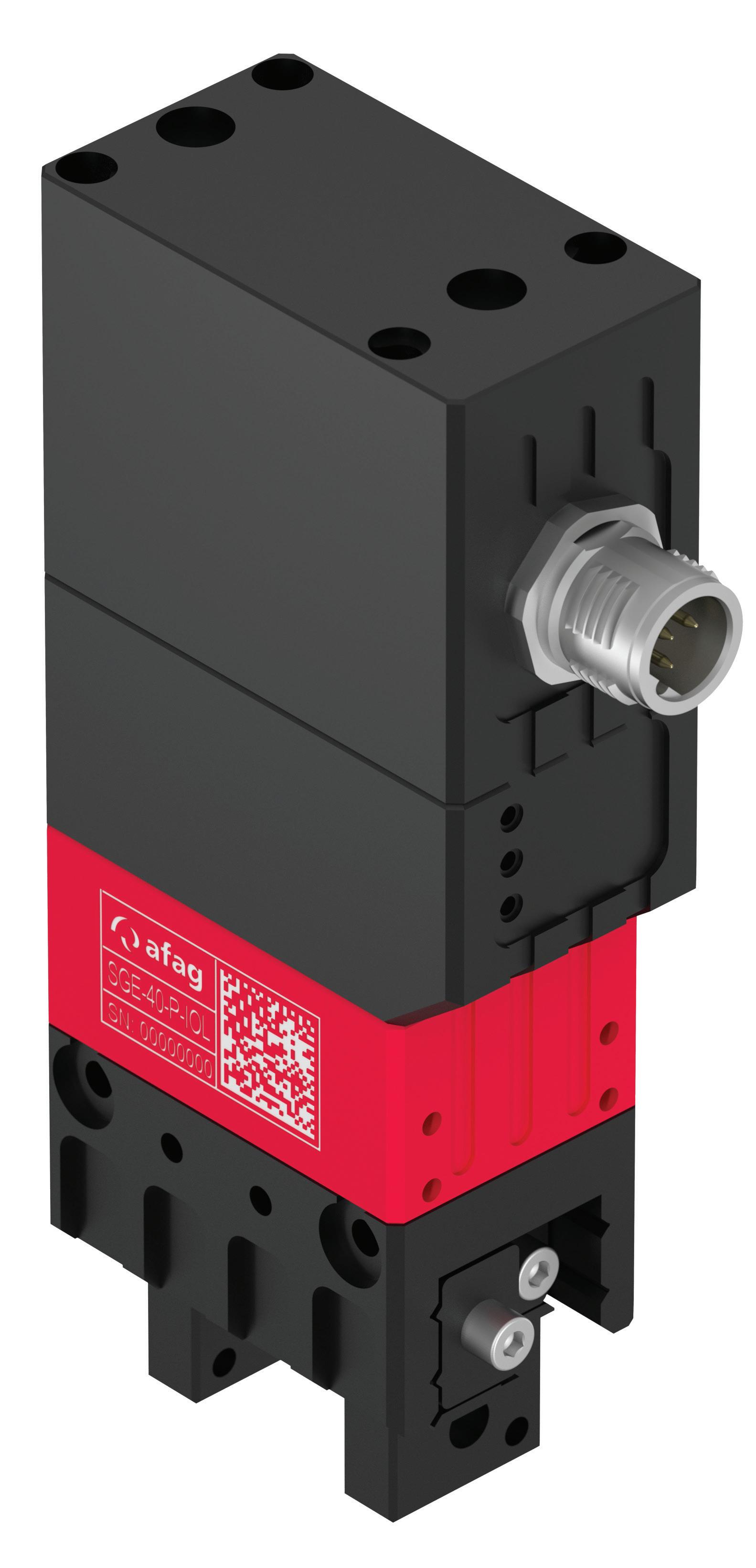
The AVENTICS SGE-40-PIOL smart electric gripper can grip up to eight different workpieces. It provides fourstage adjustable gripper force through IO-Link for easy adjustments to sensitive workpieces. Emerson
In general, electric linear actuators can be easily categorized according to their drive mechanics. There are three broad categories of electric linear actuators: toothed belt-driven actuators, screw drive or spindle drives, and linear motor actuators.
Each has specific speed, load bearing, accuracy, and other functional characteristics that guide actuator selection, based on specific manufacturing requirements.
• Toothed belt-driven actuators: A belt-driven actuator has an electric drive that powers a toothed rotator at one end of the module. This model converts rotary motion to linear motion by means of a toothed timing belt connected between two pulleys at either end of the drive.
Belt-driven modules work well when the linear sequence calls for medium repeatability, approximately 0.05 mm in motion, although higher repeatability can be supported with the use of integrated direct measuring system sensors.
Typically, they can support moving mediumsized loads up to 300 kg. They can also work well with larger strokes and sequences requiring a motion velocity greater than 5 m/ sec. Available in a wide range of profile sizes and lengths, belt-driven linear modules are well-suited for building multi-axis systems such as pick-and-place and Cartesian motion systems suitable for packaging applications.
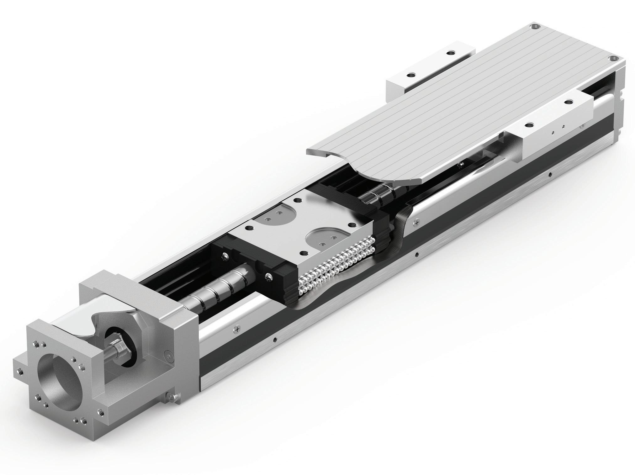
• Spindle or screw drive actuators: In these systems, a spindle or screw in the center of the actuator converts the rotary motion to linear motion to move the load. They provide high rigidity and low deflection, enabling greater endpoint accuracy with each duty cycle for applications requiring approximately 0.02 mm repeatability.
These actuators support low to medium dynamics for applications requiring velocities up to 1.5 m/sec. Their strength and rigidity also make them highly suited for placement and pressing applications where high force is needed, such as securely inserting an
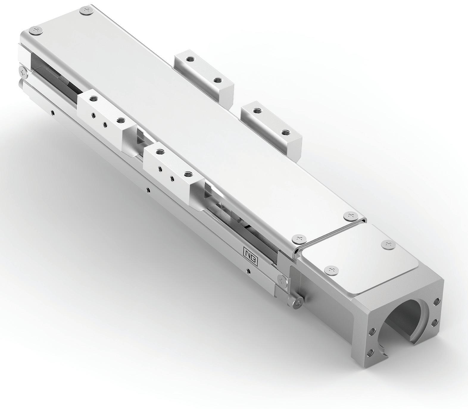
Why our single axis ball screw slide guide bests the competition:
Circuits positioned closer to base for more stability
Four ball circuits (not just two) for moreload and accuracy
Single, U-shaped rigid steel rail and base can be one-end supported
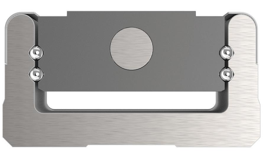
Balls have 4, not just 2, points-of-contact to guide block and rail for optimum stability

electric component into a larger assembly like an electric vehicle battery. They’re also a good choice for vertical applications.
• Direct drive actuators: In these modules, the belt or spindle is replaced with an electric linear motor that moves the module’s carriage directly, rather than converting rotary to linear motion. They support high endpoint accuracy, up to 0.01 mm, in part because the force is directly implemented at the moving part (carriage) with no elastic components in between (e.g., the rubber toothed belt). This level of accuracy is ideal for improving quality during the manufacturing of drug delivery systems such as auto injectors.
This direct control also makes complex start/stop, forward/ backward motion sequences possible by programming the linear motor controller. It also supports the broadest range of velocities up to 10 m/sec, as well as slow and constant movement — which can be a requirement for moving delicate electronics or other products that are susceptible to damage (e.g., laser applications or printing to achieve a consistent result).
Direct drive actuators are often available in compact sizes, making them a good option for
manufacturers that need to conserve valuable floor space without sacrificing performance.
Create an application requirement profile
Every automation machine and production line has unique operational and performance requirements, including the unique specifications for linear motion and transport. To determine which linear actuation system will best meet the needs of an application, automation system designers should create an application requirement profile to guide actuator selection.
First, clearly define what task each actuator must perform in a machine or production line. That requires defining the motion profile for each actuator — and in some complex automated assembly systems, different process steps will call for different actuators with specific capabilities.
A linear actuator motion profile defines key parameters such as load weight, moving mass and motion dynamics like speed and acceleration. Moving mass includes the material or component being moved, along with the total mass of the actuator, cabling, integrated measuring devices, end gripper,s and other elements that make up the total load to be moved.
The stroke must also be defined: the distance the load must be moved and with what force. This last parameter is
especially important if an actuator needs to firmly place or insert a component into a larger assembly. When assessing the force, it’s important to factor in the direction of movement.
Along with these factors, defining the duty cycle is critical for selecting the most reliable actuator based on the expected long-term performance. For example, there are now modules available that are qualified for 40 million duty cycles, which can help with rapid, high-throughput motion sequences. Within the duty cycle, pause times must also be considered. There is a big difference between actuators that move constantly and actuators that only move during one shift.
Once defined, the requirement profile gives automation designers the critical criteria for choosing the optimal electric linear actuator for each part of a new machine or assembly line. It’s also important to note that in some motion control applications, pneumatic actuators or electropneumatic hybrid systems may provide an equally efficient and costeffective solution.
For example, when combining multiple belt-driven linear actuators into a Cartesian handling system for a pickand-place application, pneumatics may be the most efficient way to actuate the gripper at the end of the Z-axis module in the system.
In a centralized motion system, electric linear actuators are connected by cables to a central control cabinet. With this approach, automation designers must specify a compatible actuator, motor and drive, then engineer a central cabinet solution. This results in a complex system with extensive cabling that can lack the flexibility and scalability needed to meet changing demands.
A decentralized automation approach eliminates the need for a control cabinet and extensive wiring. Controls, the motor and drive are all integrated with
Italian machine builders lead the way in machine and process innovation.
Machines Italia’s Fall 2025 issue will focus on how technology-focused innovations makes Italian machinery a standout in the market; how Italian machine builders are overcoming industry challenges through new/innovative/creative design applications and design solutions on their machinery and lines; how Italian innovation in machinery can help drive down organizations’ operating costs; and how Italian OEMs are working in a collaborative way with end users to bring new innovations and new transformative processes to industries. This issue will seek to place special emphasis on what makes Italian machinery uniquely superior in the market and how Italian machinery and solutions are being used in new, innovative ways to solve old industry challenges.
For more details and to read the digital edition, visit machinesitalia.org


the actuator. Using a modular approach, these systems are pre-commissioned and designed to work together.
Electric linear actuators with integrated controllers that support industrial communication protocols like IO-Link can streamline design, accelerate integration, and power process monitoring capabilities. By transmitting critical data in real time to edge devices, these systems can contribute to control operations and further advance OEE improvement.
Without the limitations of a central control cabinet, these modular linear actuators can improve flexibility and scalability, letting engineers add new equipment without the need to overhaul the cabinet. Additionally, many of these modular handling systems also reduce internal moving mass, leading to lower energy consumption and higher process reliability.
The benefits of these decentralized systems extend beyond flexibility, reliability, and ease of use. There
are control-integrated electric linear actuators available today that can provide payload capacities of up to 300 kg, repeatability of ±0.05 mm, speeds up to 5 m/sec, and acceleration up to 120 m/sec2. This level of performance and accuracy can significantly elevate overall production line productivity.
The precise, consistent motion of linear actuators make them ideal for improving OEE values for companies in a wide range of industries. Powered by electroservo drives and motors and connected to production system PLCs, electric linear actuators can provide more agile and flexible control of critical motion factors such as speed, cycle time, endpoint accuracy, and repeatability.
Navigating the broad range of electric linear actuator options to design an optimal automation system can seem
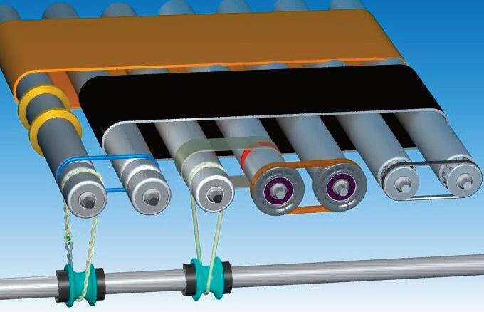
« Abuse Resistant Belts work where others fail.
« Super Strong Joints are virtually unbreakable.
« High Tension Belts move heavier loads.
« HEHT black belts double capacity.
« Low cost, highly efficient, elastic flat belts.
l
l
overwhelming. But it’s important for system designers to remember that they’re not on their own. Working with an experienced automation technology and software provider can offer engineers the support to quickly identify the most effective solution for their application.
To find one, it's important to assess the depth and breadth of the product portfolio, as well as the tools and services they can offer. Access to a broad range of electric and pneumatic linear actuators as well as accessories, sensors, hardware and software can offer greater design flexibility.
Providers at this level often offer online selection, configuration, and ordering tools that streamline the design process. Using these intuitive tools, system designers can quickly select and configure modules based on application and performance requirements. DW
IN INDUSTRIAL SETTINGS, machines are exposed to vibrations and shocks that can damage the equipment, disrupt operation and compromise the safety of human operators. Industries ranging from aerospace and manufacturing to medical devices rely on an effective isolation solution to address these challenges.
Sorbothane offers a versatile material for various application needs including shock absorption, vibration isolation, gasket sealing, space-efficient acoustic absorption and more. David Church, President of Sorbothane, Inc., spoke with Design World to discuss the unique properties of Sorbothane Performance Material in attenuating shock and vibration.
DW: For our readers who may not be familiar with Sorbothane, tell us a bit about the company and what you do?
DC: Sorbothane Inc. is the manufacturer of a unique material called Sorbothane, which is used in applications involving shock and vibration. We have been in operation for over 40 years, with our headquarters located in Kent, Ohio. Our decades of experience applying Sorbothane to medical devices,
shipping and packaging materials have yielded effective results that isolate shock and vibration issues through the design of the shape factor.
DW: What products do you offer to industrial customers seeking solutions for shock and vibration?
DC: We offer over 600 standard industrial products for customers to choose from. However, as the complexity of every industry increases, many customers require a custom design. We’re distinctive in the business because 80 percent of our designs are custom. Our material allows us to create various shapes, thicknesses and durometers to meet application-specific needs.
DW: What makes Sorbothane Performance Material unique in terms of its shock and vibration damping properties?
DC: Sorbothane is classified as a viscoelastic material that exhibits fluid (viscous) and solid (elastic) properties. It’s a thermoset, polyether-based polyurethane material that combines shock absorption, good memory, vibration damping and vibration isolation. While many alternatives offer
one of these properties, Sorbothane exhibits all of them in a stable and longlasting material.
Essentially, the Sorbothane material absorbs energy from shock or vibration and converts it into heat to help dissipate that energy. Depending on the application, Sorbothane can absorb up to 94.7% shock energy and over 50% vibration energy.
DW: What are the key factors companies should consider when selecting a shock and vibration solution?
DC: Key design considerations depend on the application. Customers should assess factors such as the required frequency, the magnitude of shock loads and any space constraints. From there, we collaborate to provide a tailored solution. We also offer engineering guides and design calculators to help customers meet shock and vibration specifications. DW
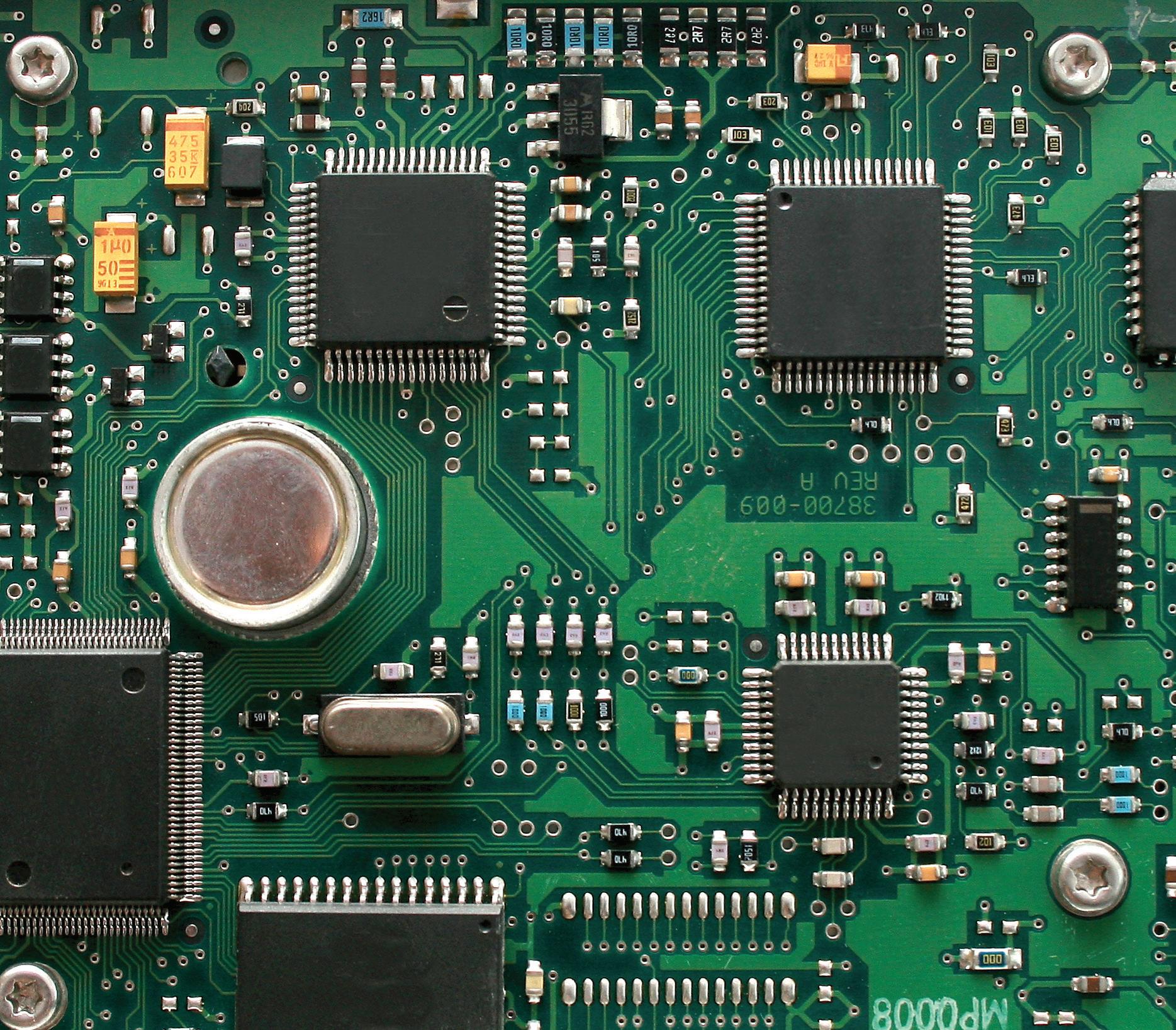
1. A PCB with multiple integrated circuits (ICs), passive components, and interconnections that enable highperformance electronic systems. sundesigns
AHARON ETENGOFF CONTRIBUTOR
PCBs are the backbone of electronic systems that support every industry and application. To optimize design and production, engineers must prioritize layout solvability, performance, and manufacturability at every stage.
Aprinted circuit board (PCB) provides the mechanical foundation, electrical interconnections, and signal routing for electronic devices and systems (Figure 1). By enabling compact, reliable, and high-performance circuit integration, PCBs support various industrial, medical, and consumer applications in data centers and at the intelligent edge.
This article discusses the three pillars of effective PCB design and production, exploring the initial design phase and explaining how fabrication transforms PCB designs into physical boards. It also highlights the placing and soldering of
components in PCB assembly, the verification of functionality and reliability during PCB testing, and key design and manufacturing considerations that span the entire process.
As shown in Figure 2, electronic engineers typically focus on three key priorities throughout the PCB design and production stages.
• Layout solvability: addresses complex packaging challenges, confirming components are optimally placed
and routed within design parameters.
• Performance: ensures signal integrity, power distribution, and thermal management meet electrical and reliability requirements.
• Manufacturability: integrates design for manufacturability (DFM), design for assembly (DFA), and design for testability (DFT) processes to maximize PCB manufacturing yields and minimize production costs.
Notably, checklists play a critical role in verifying compliance throughout PCB design and assembly. The checklist’s contents span internal guidelines to industry standards such as Institute for Printed Circuits (IPC) specifications, supplier-provided requirements, and customer-defined criteria.
The PCB design phase defines customer requirements, establishes a foundation
for reliability, and forms the basis of an initial checklist. Engineers assess key system-level electrical parameters, such as current limits, operating voltages, signal types, and capacitance constraints. Additional considerations cover impedance characteristics, shielding requirements, and major circuit component selection.
The mechanical input stage defines physical features, such as board outlines, mounting and tooling holes, slots, cavities, and component locations. Engineers also identify keep-ins, keepouts, and height restrictions to ensure mechanical compatibility. Afterward, as shown in Figure 3, they perform schematic verification to confirm that the circuit design matches the intended functionality and logic.
A design rule check (DRC) then uses EDA tools to validate trace widths, spacing, clearances, and other critical constraints against design requirements.
Subsequent design stage checks include:
• Component placement: optimizes layout for signal integrity, thermal performance, and manufacturability. Proper placement reduces noise, improves heat dissipation, and simplifies assembly.
• Signal integrity analysis: simulates high-speed and radio frequency (RF) signals to mitigate crosstalk, reflections, and electromagnetic interference (EMI). Proper signal routing ensures all traces reference a continuous ground plane to minimize noise.
• Power distribution network (PDN): verifies power and ground layer coupling, decoupling capacitor placement, and low-impedance power delivery. Balancing power integrity with signal routing involves tradeoffs, requiring thorough analysis to maintain design intent.


BAYCABLE, with over 20 years of experience partnering with leading semiconductor equipment OEMs, collaborates closely with customers' engineering teams during product development to deliver custom, application-specific interconnect solutions that meet the semiconductor industry's strict copy exact standards and ensure repeatability, reliability, and performance in demanding environments —leveraging our expertise in designing and fabricating high-power, molded power distribution assemblies using BAYCABLE-manufactured cable, from 50 AWG to over an inch in diameter, with tailored material selection and configurations to address flex life, chemical resistance, temperature extremes, and complex integration of power, signal, fiber, tubes, and structural elements



Design For:
DFSolvability
DFPerformance
DFManufacturability
Skill set to solve the placement and route of our circuit. Often with complex High Density Interconnect (HDI) and master this on your CAD Tool.
Signal Integrity/EMC
Power Delivery Thermal
THE RESULT: Maximum placement and routing density, optimum electrical performance and efficient, defect-free manufacturing.
• DFM analysis: verifies compliance with industry standards and best practices to maximize yield and minimize production costs. Key manufacturability constraints include minimum trace widths via structures and solder mask clearances.
The fabrication stage transforms PCB designs into physical boards. Engineers first verify Gerber file accuracy, ensuring proper layer alignment, drill file integrity, and overall design consistency. They then document specifications to ensure the manufacturing process matches design intent and requirements. Additional fabrication stage checks span:
• Layer registration: confirms precise alignment of multilayer stacks to prevent misregistration, which can lead to connectivity failures or impedance inconsistencies.
• Material quality: ensures the PCB substrate meets required thermal and electrical performance specifications, such as dielectric constant, loss tangent, and coefficient of thermal expansion.
• Solder mask and surface finish:
verifies uniform solder mask application and consistent surface finish, including hot air solder leveling (HASL) and electroless nickel immersion gold (ENIG). This protects exposed copper, prevents oxidation, and confirms reliable solderability.
• Via quality: checks that vias are properly plated and, if required, filled to maintain robust interlayer electrical connections and mechanical reliability, reducing the risk of open circuits or premature failure.
One of the first steps in PCB assembly is solder paste deposition, where automated machinery applies solder paste onto designated pads before component placement and soldering. Once this stage is complete, engineers place and solder components onto the fabricated board, verifying orientation and ensuring proper alignment of polarized components such as diodes, capacitors, and integrated circuits (ICs). They also inspect solder joint integrity, confirming joints are smooth, shiny, and free of cracks, voids, or bridging.
DFX (DFM) all considerations producing high yield and lower cost
FIGURE 2. Electronic engineers must balance three key priorities to achieve optimized PCB design and production. Siemens EDA
Additional assembly stage checks cover:
• Pick-and-place accuracy: ensures automated assembly machines precisely position components on designated pads, preventing misalignment that could impact electrical performance or manufacturability.
• Thermal profiling: optimizes the reflow soldering process to prevent thermal damage to components while ensuring strong, reliable solder joints.
• Cleaning and coating: removes flux residues, and if required, a conformal coating is applied to protect the board from moisture, dust, and environmental contaminants that could degrade performance.
Testing confirms the assembled PCB meets all functional and reliability requirements, whether using flying probe or bed-of-nails methodologies. Electrical testing evaluates continuity and isolation, verifying proper connections and the absence of shorts to prevent unintended signal paths. Functional testing then confirms the PCB operates as intended
under normal conditions, assessing power distribution, signal integrity, and component interactions. Additional testing protocols include:
• Boundary scan testing: uses the Joint Test Action Group (JTAG) standard to diagnose connectivity issues in inaccessible pins and verify IC functionality without physical test probes.
• Environmental testing: subjects the PCB to temperature cycling, vibration, and humidity exposure to evaluate durability and long-term reliability under real-world conditions.
• In-circuit testing (ICT): analyzes individual components and their
electrical connections within the assembled board, identifying faulty solder joints, missing components, or incorrect values.
Comprehensive documentation and close collaboration with external suppliers are essential throughout PCB design and production. Documentation encompasses schematics, bills of materials (BOMs), fabrication drawings, assembly instructions, and test procedures. Each document must be accurate, up-todate, and aligned with the intended design. Compliance with industry
standards — such as IPC-2221 for design, IPC-A-600 for fabrication, and IPC-A-610 for assembly — ensures quality and consistency across the PCB lifecycle. DW

SCAN THE QR CODE FOR A LIST OF REFERENCES USED IN THIS ARTICLE
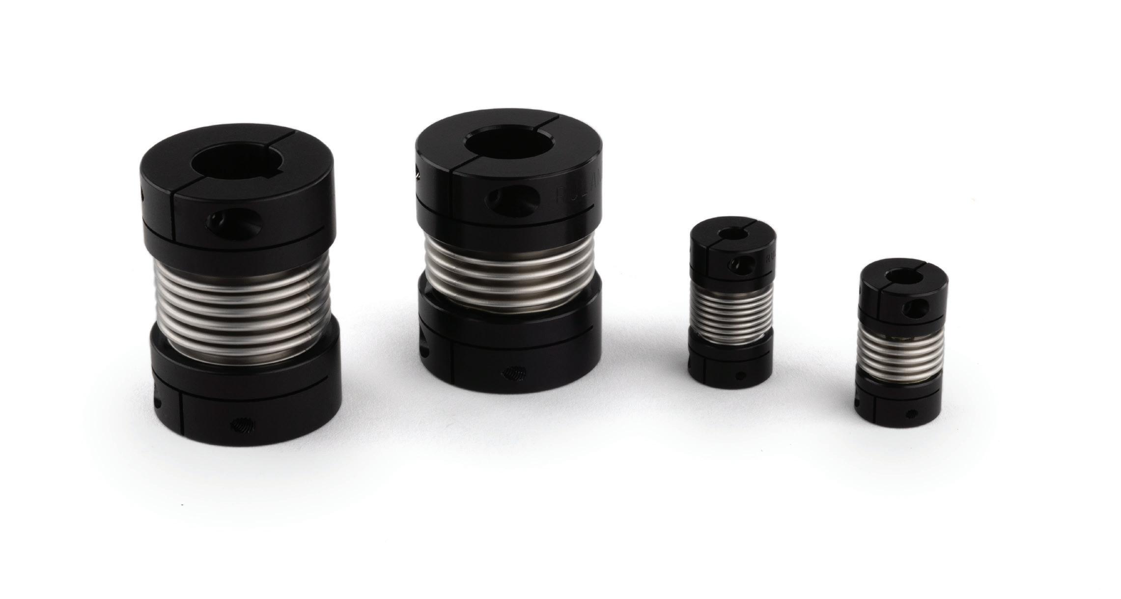
This article provides a comprehensive comparison of coupling styles, shedding light on the critical attributes of each coupling type and guiding you toward the right fit for your application's specific demands. Bellows couplings have the highest torque and torsional stiffness capabilities of these flexible couplings at the expense of misalignment. They are comprised of two aluminum hubs and a flexible center element called a bellows. The thin walls of the stainless-steel bellows flex while remaining rigid under torsional loads,
giving bellows couplings high rigidity to transmit position accurately in the most demanding applications. Bellows couplings are designed for applications requiring precise rotation and dynamic motion, making them a suitable choice for the most demanding servo-driven applications.
Functionally, disc couplings are close to bellows couplings but have slightly more misalignment capabilities at the expense of torque and stiffness. They are available in single- and doubledisc styles. The single disc style is

aluminum hubs, a center spacer, and two sets of disc springs. This
speed capabilities. This combination of performance characteristics makes them a suitable interchange
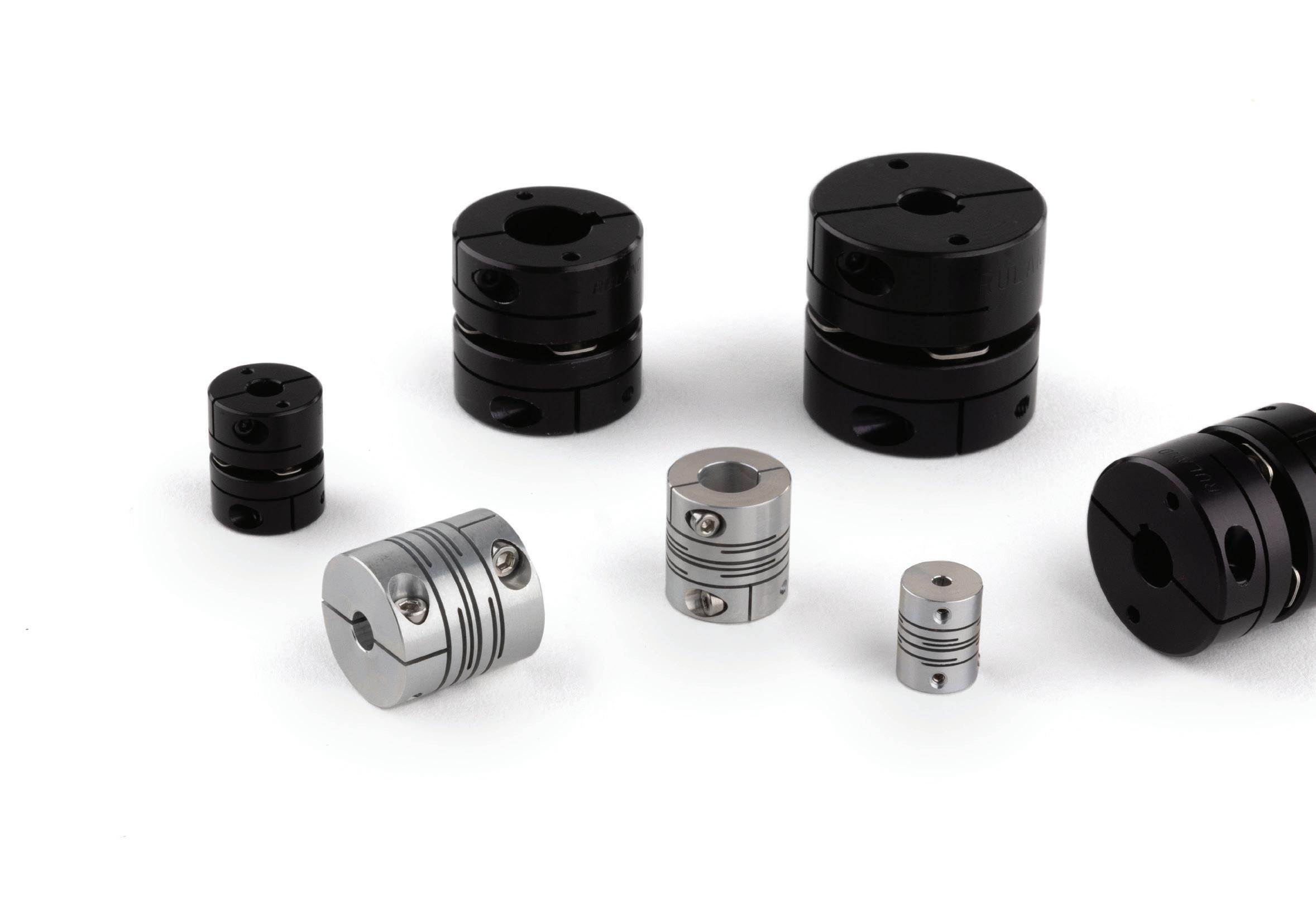
for couplings such as single disc, which has misalignment and speed limitations. Slit couplings come in long and short styles. Short styles have higher stiffness, while long ones have increased misalignment capabilities. Speed is a primary differentiator with slit couplings compared to the other high-torque couplings. Bellows and disc couplings max at 10,000 rpm. Slit couplings, in comparable bore sizes, have speed capabilities up to 30,000 rpm.
The chart for torque comparison of similarly sized couplings helps select the right coupling type and style, giving an idea of how the couplings stack up against each other. There can be variations depending on the outer diameter size of the coupling.
When selecting a high-torque coupling, it is critical to understand all factors to make the right choice. Each
coupling style brings its own set of strengths and weaknesses, tailored to meet specific high-torque challenges. Bellows couplings provide Ruland servo couplings’ best size-for-size torque capabilities with limited misalignment capabilities. Disc couplings have higher misalignment than bellows couplings
DATORKER® STRAIN WAVE GEARS
Available in Standard, Heavy Load, and Lightweight Configurations. Offering High Precision, Efficiency, Torsional Rigidity, and Low Starting Torque.
CROSSED ROLLER BEARINGS
Lightweight And Compact Design. Easy to Install and Maintenance. Varieties of Bearing Types and Sizes for Solution.
with slightly reduced torque capabilities. Slit couplings have better misalignment and can fit in more confined spaces than a disc or bellows coupling. Choosing the proper coupling allows the system to maximize its performance. DW Ruland • ruland.com
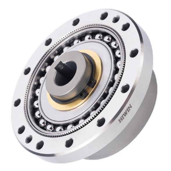
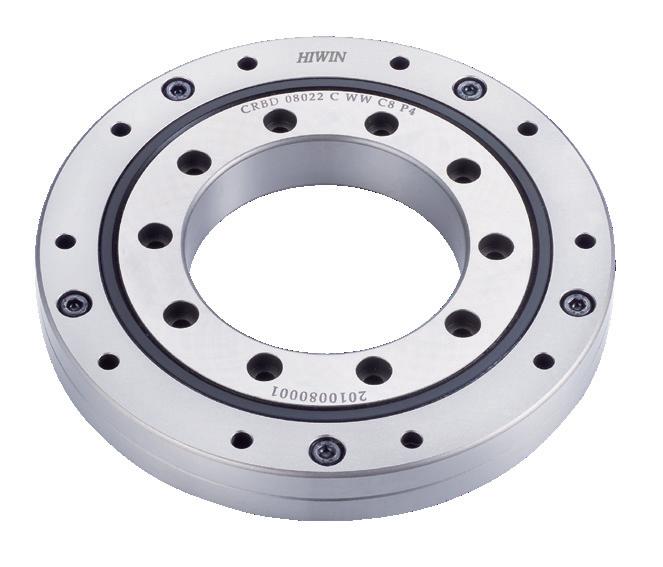
12455 Jim Dhamer Dr. Huntley, IL 60142
Phone: (877) 804-4946
Fax: (847) 827-2291

Our engineers are available to assist in finding the ideal solution to your application. Contact us for details.
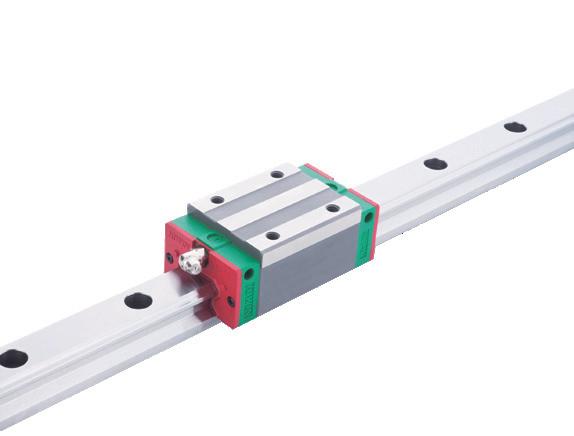
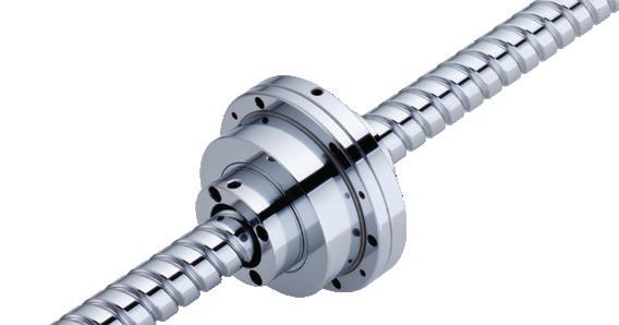
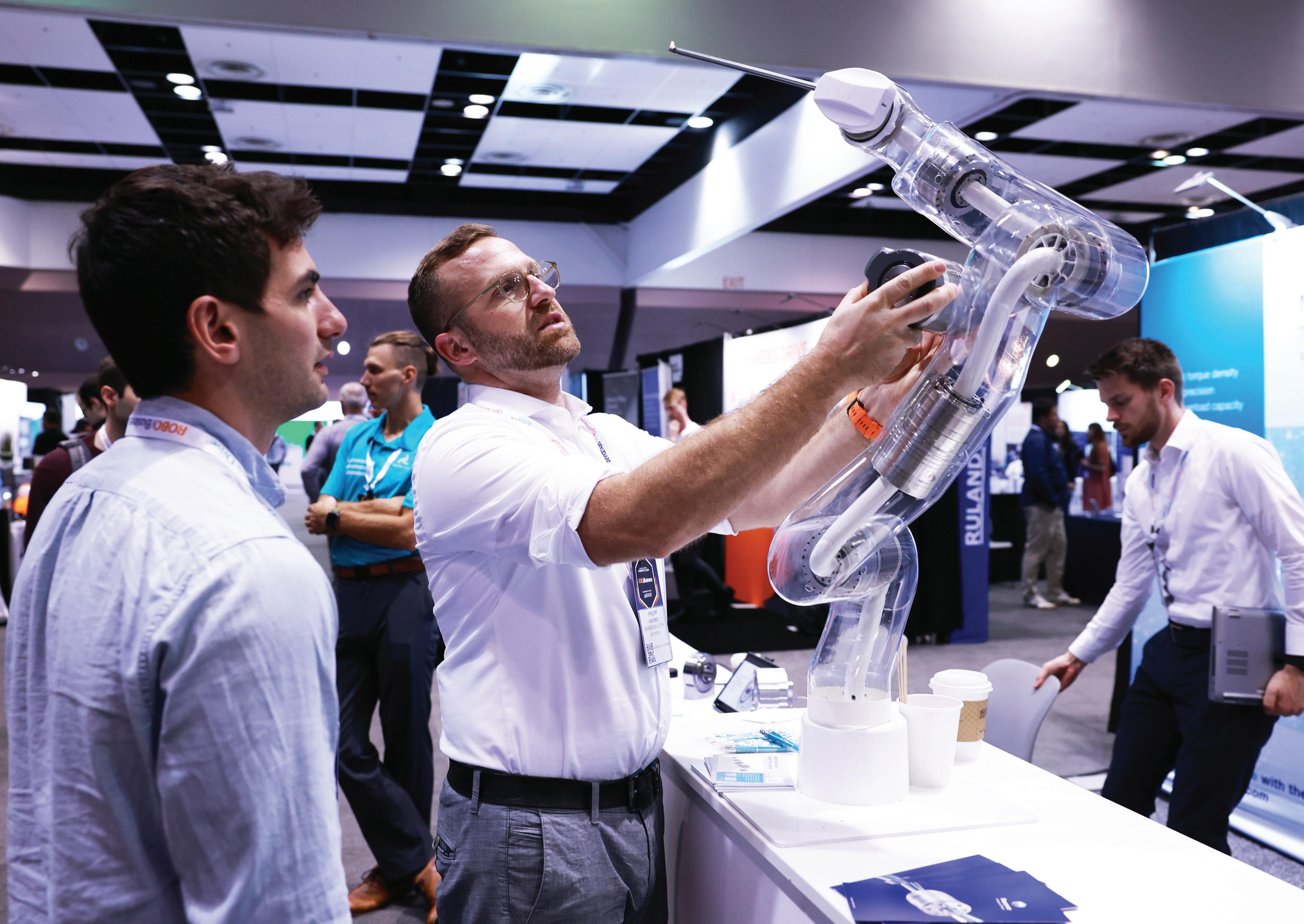

“Thread galling” or “cold welding,” as the term is often called, occurs during the installation of bolts and nuts where the bolts are twisting off and/or the bolt’s threads are seizing to the nut’s threads.
Thread galling seems to be most prevalent with fasteners made of stainless steel, aluminum, titanium and other alloys which self-generate an oxide surface film for corrosion protection. During the tightening of the fastener, pressure builds between the sliding contacting thread surfaces and breaks down the protective oxide coatings.
Possibly the coatings are wiped off and interface metal high points shear,
friction increases, and the fasteners lock together. This cumulative clogging-shearing-locking action causes increasing adhesion. Galling leads to fusing and seizing — the actual freezing together of threads because of the heat generated. If tightening is continued, the fastener can be twisted off or its threads stripped out.
Four suggestions to minimize thread galling in stainless steel fasteners:

1. Use coarse threads with 2A-2B fit instead of fine threads. UNC coarse threads have a greater thread allowance than UNF fine threads and are more tolerant to abuse during handling.
2. Slowing down the installation RPM speed will frequently reduce or sometimes completely solve the problem. As heat from friction increases during installation with too rapid RPM, so does the
tendency for occurrence of threads galling. In general, a stainless steel bolt of a given size should be driven slower than a steel bolt of the same size. Slow down the wrench speed!
3. Lubricating the internal and/ or external threads frequently eliminates thread galling. Suggested lubricants should contain substantial amounts of molybdenum disulfide (moly), graphite, mica, or talc. Some proprietary extreme pressure waxes may also be effective. However, you must be aware of the end use of the fasteners before settling on a lubricant. Stainless steel in certain environments precludes the use of some lubricants, for example the food processing equipment industry. In application, if the problem is repetitive, try to supply fasteners with a pre-applied lubrication to eliminate future galling problems. Also note; that the use of lubricants will change the torque-tension relationship.
4. Using different stainless alloy grades for the bolt and nut reduces thread galling. The key here is the mating of materials having different hardness’ numbers. Different stainless steel alloys work-harden at different rates. Try using type 316 stainless and 304 stainless for
your components and increase the likelihood of eliminating thread galling in the application.
Thread roughness is another factor affecting thread galling in stainless steel fastener applications. Rolled threads offer a smoother surface than cut threads. The rougher the threads flanks, the greater the likelihood of thread galling. Although it may seem the bolt is the problem because it is breaking and the cause of the problem; in reality it is the internal threaded fastener, the nut. This is because the bolt has smooth rolled threads from the rolled threading process.
Internal threads are always cut threads, producing rougher thread flanks than the bolts they mate with. The reason thread galling problems are inconsistent is probably due largely to the inconsistencies in the tapping operation. Rougher than normal internal threads may be the result of the use of dull taps or the tapping operation may have been done at an inappropriately high RPM.
Knowledge of knowing why thread galling occurs and how to remedy it can save you a customer. Don’t panic, try the suggestions from above. One, or a combination of these, will most likely solve the problem. DW
what does galling look like?
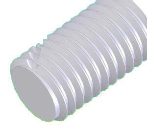

Galling occurs when threads are damaged by material sticking and getting torn off.
EDITED BY MIKE SANTORA
How do you know if your PE parts are going to live up to a manufacturer’s specs? After all, every company claims quality. How do you prove it?
Milford Center, Ohio-based Advanced Technology Products (ATP) had spent three decades answering this question with a manual testing apparatus that essentially boiled down to a roughly foot-long stretch of tubing, a hand pump, an analog pressure gauge, and someone watching and saying, “That sort of looked like pressure fell off when the tube burst at…500 psi? Eh, call it 510.” ATP wasn’t cutting corners. There simply wasn't a better QC testing option available. ATP had always published a working tube pressure in its catalog, stating either
Imagine staking your trucking fleet, manufacturing floor robots, or irrigation system on the integrity of the polyethylene (PE) tubes linking their components.
a 3:1 or 4:1 safety factor, depending on the specific part. (For example, a PE tube rated for 100 psi would be able to sustain 300 or 400 psi under given conditions.) ATP and their customers grew more concerned about safety test data reliability and began to explore options to better record and capture burst pressure data. ATP became ISO certified in 2023, and ISO standards were also a factor driving this search. If customers had service questions about their tubing, ATP needed a more streamlined, accurate way to investigate issues. In short, the testing tech that sufficed for ATP yesterday would not get the firm to where it needed to go tomorrow.
ATP reached out to Indianapolis-based Flodraulic USA to help devise a new pressure testing apparatus. The result, as shown in the image below, is a fivestation, safety-sealed, stainless-steel stand with five independent water test cells. Each cell can test one tube. All five can pump either air or water. Four can accommodate up to 1000 psi of water pressure while the fifth, which also includes temperature control, can reach up to 3600 psi.
With the station designed, the next challenge became how to control the various pressures and temperatures across the test cells. Flodraulic reached out to Advanced Industrial Products
(AIP, also based in Plain City, Ohio) and Delta Motion in Battle Ground, Washington. The group ultimately settled on Delta’s RMC200 motion controller, configured with the 20L CPU/power supply, CV8 (eight control outputs), A8 (eight analog inputs), and the D24 I/O module. Flodraulic built the rest of the panel, from power supply to relays to the AutomationDirect touchscreen operator interface.
With this HMI, users select which pump/test chamber they want to use. They then set target pressure, rampup time/rate, and heat (for the fifth tank). The ramp time applies five minutes of sustained pressure in the tube to better resemble in-service rather than fresh-off-the-roll tubing (much like stretching a balloon before inflating it). The system also requires that each chamber be sealed and locked before operation can begin. Delta’s RMCTools captures all the resulting data, including the exact burst pressure, and compiles it for easy reference and analysis.
Flodraulic selected Delta Motion’s RMC200 for several reasons. AIP’s tube testing system needed to control up to eight axes, and, according to Flodraulic, the RMC200 offered the best multi-axis support combined with a compact form factor, low cost, high build quality, and suitable digital I/O connectivity for monitoring.
It also helped that Delta has hundreds of sample programs freely available to all users. AIP perused Delta’s collection and found the one closest to its own needs. From there, it was simply a matter of tweaking the instructions for ATP’s specific use case.
“We had to control five Airoyal pumps and integrate those with five proportional regulators,” said AIP owner Mike Joyce. “Those integrated with another six pressure transmitters we had. And, of course, we had to record all that data. With the Delta, we could do all that plus plot everything. When the tube burst, it would display on the screen so ATP could write it down, and they could plot it out to show the customer exactly what the pressure was at that moment of failure. You can do all this through RMCTools.”
“It was a unique machine that had never been done before,” said Flodraulic’s Chris Hart. “Everyone had to learn as we went. It took a year to get the machine ready for
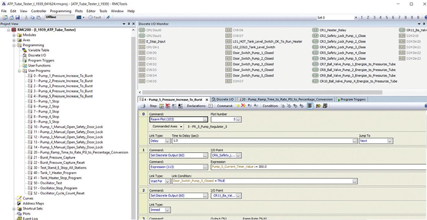
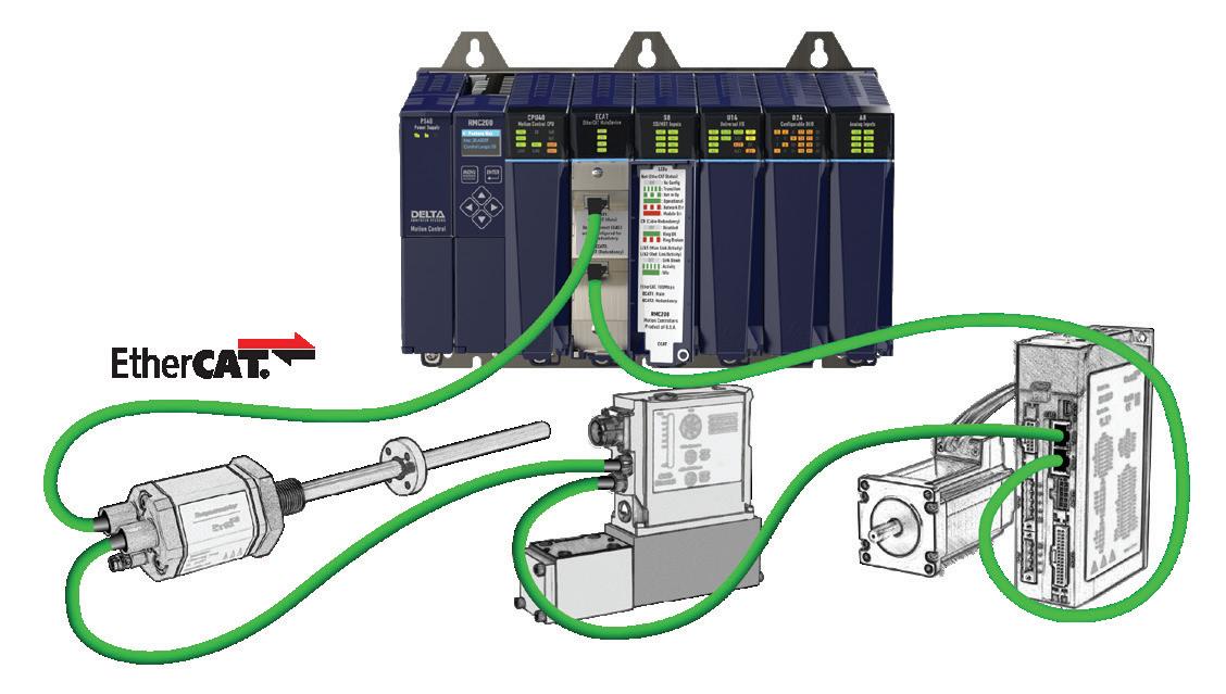
programming, but the programming at the end took less than a week — maybe twenty hours. That’s a day for the HMI programming, three for the Delta RMC programming, and a day or so to get the customer up and running.”
When ATP runs a tubing lot for a customer, the company cuts off a certain amount, tests a portion for pre-shipping QC, and then keeps the remaining section. This way, if the user ever has a problem with that tubing, ATP can simply retest it. This gives ATP a secondary means to follow up on queries after the initial qualification.
This new capability has already paid off. For example, ATP had a customer running hot water (which changes the burst pressure) through the wrong tubing. Not surprisingly, the tubing failed prematurely. Retesting allowed them to identify and replicate the issue, then go back to the customer with a chance to help and educate them in how to use the product more effectively.
The success of its tube tester opens several doors for ATP. For starters, the company can now qualify its products to customers. This not only gives bulletproof, repeatable, evidence supporting its quality claims, it puts the burden of comparison on ATP’s competitors — and ATP notes that it doesn’t know of anyone else delivering this level of product durability range, especially with the ability to back those claims up with hard data.
“We can now guarantee that we’re well over spec and not running into production issues throughout ATP’s range of tubing,” said Joyce. “The other good thing with Delta is that since we’re plotting the data, we can save any of those plots and give the customer something to refer to later before they put it into a new use. They don’t even have to ask us. They already know how their tubing will perform in that new role.”
ATP’s tube testing capabilities are central to the company’s commitment to
Flodraulic selected Delta Motion’s RMC200 for several reasons. AIP’s tube testing system needed to control up to eight axes, and, according to Flodraulic, the RMC200 offered the best multi-axis support combined with a compact form factor, low cost, high build quality, and suitable digital I/O connectivity for monitoring.
improving safety. The enhanced testing process also enables ATP’s sales and service teams to confidently address customer inquiries. For example, while ATP rates its tubes at 75° F, customers may ask how the tubes perform in 220or 250° environments or under specific conditions like kinks in the tubing. With their advanced testing system, ATP can now provide clear, definitive answers to these questions.
This unique combination of clever programming, best-in-class motion control, and a commitment to accuracy and safety, now gives ATP a better option when customers demand proof of quality claims. Before, answers might have boiled down to approximation and “we checked, trust us.” Now, hard data and precision makes all the difference and is improving safety for ATP. DW
Flodraulic USA’s five-station, safety-sealed, stainlesssteel stand with five independent water test cells.
ATP and their customers grew more concerned about safety test data reliability and began to explore options to better record and capture burst pressure data. Delta Motion


For over 120 years, Bodine has delivered highquality, high-performance gearmotor and drive solutions. From its first motor in 1905 to today’s solar-powered systems, the company continues to help customers solve complex motion control challenges with innovation and reliability.



In a perfect world, companies make all the right choices to avoid the corrosion issues that can hinder an operation upon delivery. But that’s not always the way things go. To protect your organization from these kind of preventable challenges, Cortec Corporation encourages manufacturers to choose a simple but effective packaging strategy based on Vapor phase Corrosion Inhibitors.
Corrosion dangers during shipping and storage
Shipping and storage are vulnerable times for aircraft components, especially when they take place in a hot, humid environment or undergo fluctuating temperatures during export. These provide ideal conditions for corrosion to form as moisture condenses on metal surfaces inside packages and heat accelerates the corrosion process. Manufacturers and end
users may be left with corrosion damage and stains that mar appearances and call component integrity into question.
Effective protection minus greasy rust preventatives
VpCI packaging methods rely on Vapor phase Corrosion Inhibitors to eliminate corrosion in a way that keeps aircraft components dry and ready-to-use. As long as the aircraft component remains enclosed with a sufficient supply of Vapor phase Corrosion Inhibitors, it will be protected by a corrosion inhibiting layer that adsorbs on the metal surfaces. Once the component is removed from the packaging, this molecular layer begins to dissipate on its own — no cleaning of messy rust preventatives typically required. Vapor phase Corrosion Inhibitors come in a variety of forms, from VpCI film and paper to emitters and fogging fluid.

Before an airplane is assembled, its components must be manufactured and shipped to the assembly plant and sometimes stored. This critical period can lead to the uneventful arrival and installation of a propeller or engine… or it can lead to headaches and setbacks from corroded components.
VpCI packaging can take many different shapes depending on the component type and shipping or storage parameters. The following are a few possible packaging scenarios.
Propellers can be protected by wrapping CorShield VpCI-146 paper (a USDA Certified Biobased Product) around sensitive areas and heat shrinking each propeller in VpCI-126 Shrink Film before shipping to the customer.
Special crates and frames used to hold engines in place for transport can be lined with a VpCI-126 gusseted bag before placing the engine inside. Desicorr VpCI Pouches with a combination of desiccant and Vapor phase Corrosion Inhibitors can be added to the bag for dual moisture absorption
Avionics that play such a major role in aviation today may need protection against ESD (electrostatic discharge) damage as well as corrosion. For this purpose, electronics manufacturers can package avionics in EcoSonic VpCI-125 HP Permanent ESD Film & Bags.
and active corrosion inhibition. For engines heading to especially hot, humid regions, a light spray of EcoAir 337 can be added for extra corrosion protection just before the package is closed.
Avionics that play such a major role in aviation today may need protection against ESD (electrostatic discharge) damage as well as corrosion. For this purpose, electronics manufacturers can package avionics in EcoSonic VpCI-125 HP Permanent ESD Film & Bags, which contain both corrosion inhibitors and an inherently static dissipative component.
Of special note among recent applications, Lake Engineering Solutions reported in 2024 that a global aviation leader in the UK had enhanced its packaging process by adopting CorPak VpCI-126 Bubble Bags powered by Nano-VpCI. This improvement
streamlines the protection of parts against corrosion and mechanical damage, allowing the OEM to use one packaging material instead of two (regular bubble bags + VpCI-126 bags). Additionally, Lake Engineering helped a UK division of another of the world’s largest aerospace manufacturers reduce their plastic footprint by implementing Eco Wrap (certified “OK Compost INDUSTRIAL” by TÜV Austria) the previous year. After testing it with their logistics team, the OEM decided to use it as a direct replacement for the LDPE stretch wrap they had been using for internal shipment of components. By implementing packaging strategies such as those suggested above, aircraft component manufacturers can eliminate corrosion problems during shipping and storage, develop peace of mind and happy customers, and sometimes even find ways to improve their environmental profile. DW
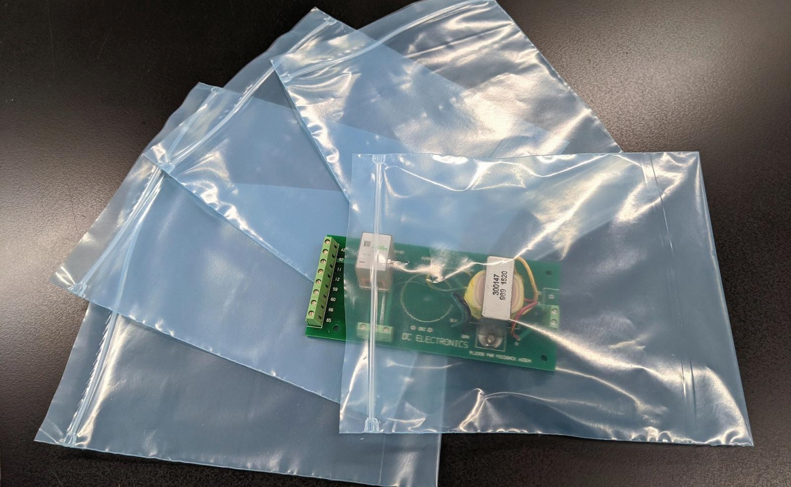
Emerson • emerson.com

Emerson has announced the release of PAC Machine Edition (PME) 10.6, the integrated development environment software used to configure and manage control system devices, including PACSystems programmable logic controllers (PLCs), QuickPanel human-machine interfaces (HMIs), and more. This update is the latest and most advanced version, elevating the user experience with a significant leap forward in capabilities, including simulation, data monitoring enhancements, optimized connectivity, and programming efficiency.
PACSystems Simulator is a newly incorporated component, empowering users to easily write, test, and troubleshoot control logic on a PLC emulator. This can be done before purchasing new control hardware to speed development and ensure the correct selections
are made. The Simulator is seamlessly integrated within PME and is easy to set up, and fast to enable with just one button. Users benefit from the ability to continuously test code throughout development, minimizing risks and accelerating project implementation.
An all-new data monitor component empowers developers to quickly diagnose and resolve logic issues using plotted data, whether the data is sourced from a physical PLC or the Simulator. With advanced configuration options for visualizing and analyzing data in a modernized display, and the ability to save and retrieve monitor configurations, users can gain insights into system dynamics, detect root causes of anomalies rapidly, and uncover trending conditions. DW
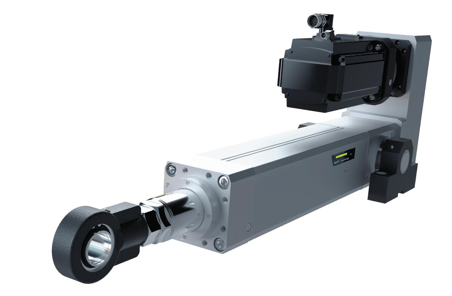
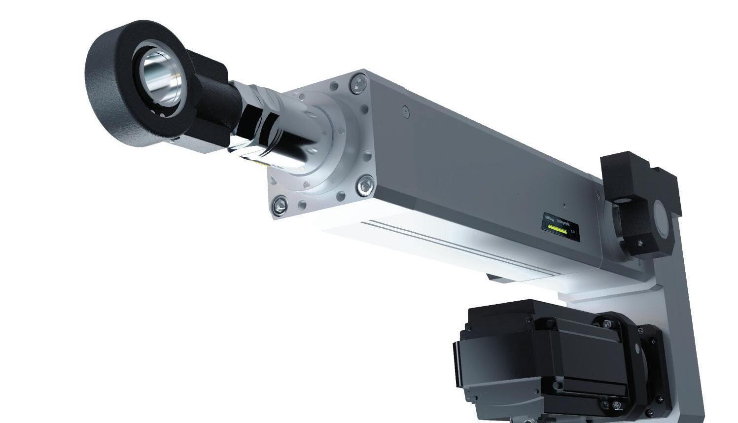
Bosch Rexroth • boschrexroth-us.com
Whether it’s pressing, forming, riveting, tensioning, positioning or testing, there are numerous processes in which linear movements with high forces must be performed precisely and energy-efficiently. As such, Bosch Rexroth is expanding the electromechanical cylinders in the EMC-HP high-power series to include sizes 190 and 220. These sizes can be implemented in heavy-duty applications with high axial forces of up to 250 kN in a precise and dynamic manner using a direct drive or a parallel spur gear configuration. An integrated sensor and display package provides a lubrication recommendation or oil temperature
(depending on the version) to ensure maximum productivity. As part of the digital quick selection, an oil bath can also be selected as a lubrication option for continuous load applications.
The new sizes meet the highest requirements of power density, precision, and dynamics, which are required in the calendaring process in battery production, wood panel pressing, and sheet metal forming. The EMC-HP portfolio has protection class IP 65 and can provide strokes of up to 1,500 mm in length. DW
AutomationDirect has added Laumas precisionengineered load cells, transmitters, and accessories that deliver reliable performance in industrial weighing and force measurement applications. The FCAL series high-precision bending beam load cells are suitable for low- to mid-capacity systems. CTL series load cells are designed for both tension and compression, with strong linearity. The CBL series low-profile compression load cells are perfect for space-limited applications. Laumas load cell transmitters provide reliable signal conversion for precise monitoring and control. Single-
channel models offer a 4–20 mA output and support Modbus RTU. Multi-channel models provide I/O for functions such as batching, taring, and alarming, and support Modbus TCP, EtherNet/IP, or a built-in web server for remote access. The Laumas Instrument Manager software optimizes multi-channel transmitters by enabling PC-based setup, real-time monitoring, and calibration, simplifying installation and reducing downtime. DW
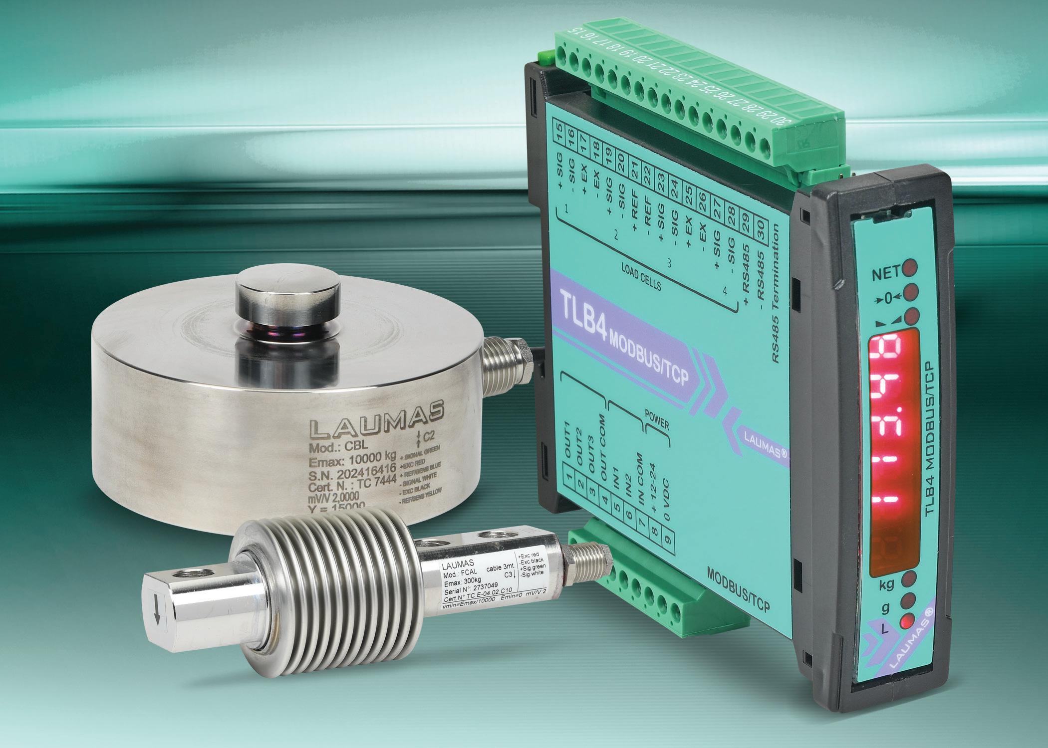
Freudenberg Sealing Technologies • fst.com
Material and sealing company Freudenberg Sealing Technologies has developed a new, highly compatible elastomer material. In the rapidly growing electric vehicle market, improved battery performance with shorter charging times, maximum temperature resistance, and a longer battery life are key factors for success. To meet these demands, OEMs in Europe and the United States need materials that also comply with stricter national and international environmental standards. Freudenberg Sealing Technologies has successfully developed a high-performance elastomer material that outperforms thermoplastics in the event of thermal runaway and takes battery applications in e-mobility to an entirely new level.
The development of new battery materials prioritizes sustainability as well as economic aspects. In general, the longer a battery can be used, the more sustainable the electric vehicles become. The new sealing material from Freudenberg contributes to this goal.
When used in customer projects, the new material has been able to improve the performance-relevant leakage rate of the battery cells by an order of magnitude — resulting in a tenfold improvement compared to conventional thermoplastic seals. In addition, process engineering has optimized manufacturing techniques to such a degree that it is possible to produce these high-performance battery cell seals in large series. DW
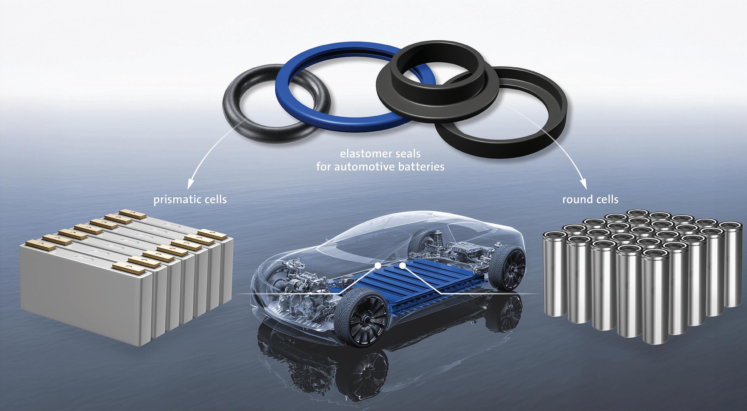
Applied Motion Products • applied-motion.com

The Applied Motion Products STF Stepper Drives and SSDC StepSERVO Drives are now UL Certified by Underwriters Laboratories. The drives now meet stringent safety standards with certification, reducing risks of electrical hazards, fire, or component failures. The STF Stepper Drives are DC-powered microstepping drives that control two-phase, bipolar step motors. They feature advanced current control and an anti-resonance algorithm that electronically dampens motor and system resonances, enhancing motor smoothness and usable torque across a wide speed range. Additionally, the drive incorporates electronic torque ripple smoothing and microstep emulation, significantly reducing motor noise and vibration for optimal performance.
The SSDC StepSERVO Drives are closedloop versions of our proven, high-performance microstepping step motor drives. By integrating closed-loop servo control algorithms and pairing them with StepSERVO Motors equipped with highresolution encoders, these drives enable StepSERVO systems that outperform traditional step motor solutions. Benefits include up to 50% higher peak torque, smoother and quieter operation, and reduced power consumption, delivering superior efficiency and performance. DW
The WES Series stainless steel gear unit is a compact, hygienic drive solution that runs cool — even under continuous operation. Unlike worm gear units that overheat, the WES Series integrates SPIROPLAN right-angle gearing, ensuring smooth, reliable performance without excessive heat buildup.
Designed for food, beverage, and other hygienic applications, the WES Series is corrosionresistant, easy to clean, and rated for high-pressure washdowns.
Key advantages:
Compact and efficient
No cooling fan, no hygiene risk — suitable for clean environments.
Always runs cool — safe and reliable
SPIROPLAN gearing minimizes friction, reducing heat compared to worm gear units. No burn hazards, ensuring worker and product safety.
Hygienic and washdown-ready
Rated for aggressive cleaning agents and washdown environments. Seamless, smooth surface prevents bacteria buildup.
Durable and low maintenance
High-efficiency gearing and lubrication systems extend service life. Lightweight, compact design for easy integration into processing lines.
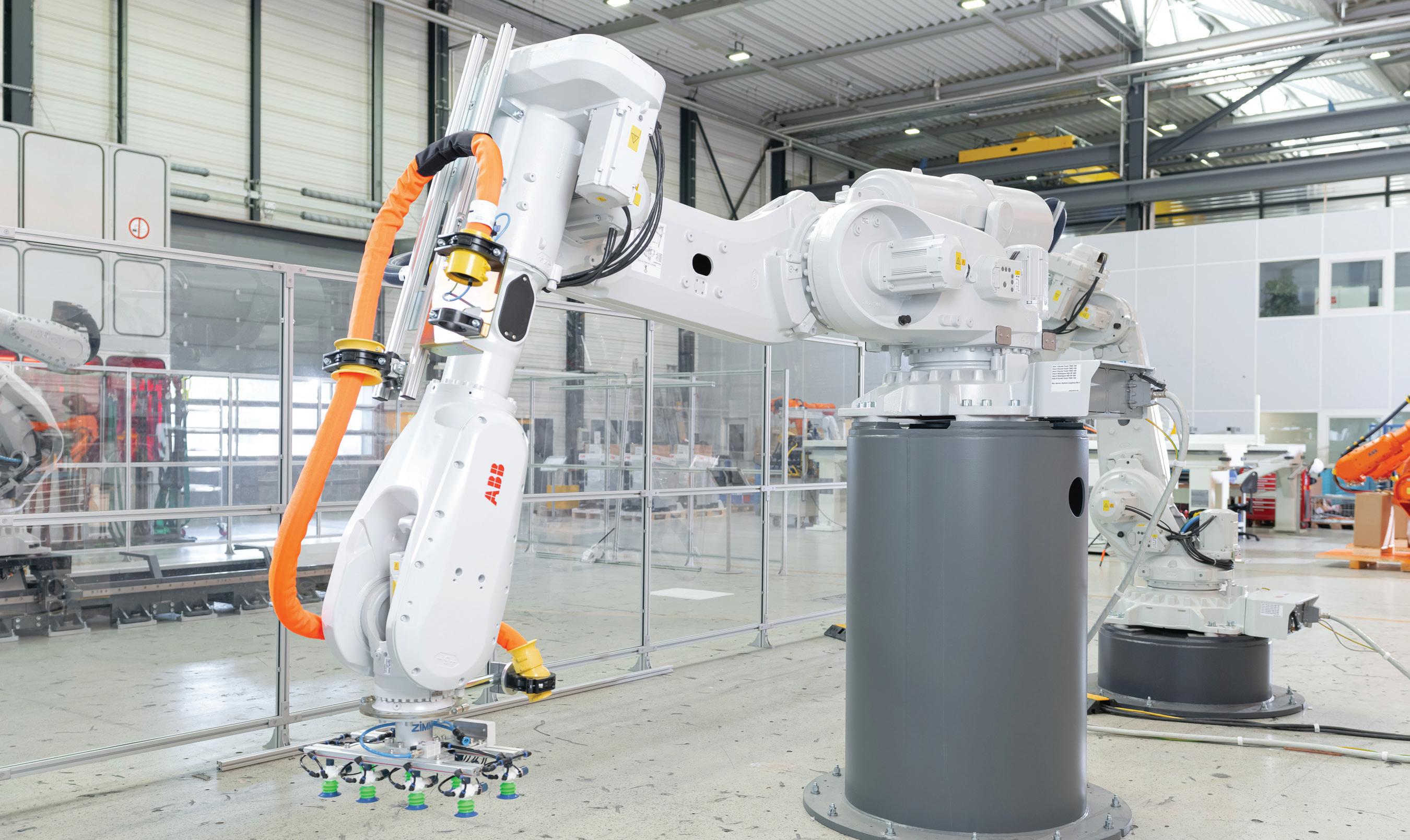
ABB Robotics is expanding its large robot portfolio with the launch of the IRB 6730S, IRB 6750S, and IRB 6760. The introduction of these new robots, alongside the wider portfolio of next generation robots launched since 2022, now means the company can offer its users a comprehensive lineup of industrial robots and variants. The lineup of 11 next-generation robot families, comprising 60 variants, offers users new levels of flexibility and choice as well as class-leading performance and sustainability benefits.
The IRB 6730S and IRB 6750S are both shelfmounted robots and have been designed to support an increase in robot density in the production line. Capable of handling industry-leading payloads of up to 350 kg, the shelf robots can be installed at a height (or on a second floor) and can work with floor-mounted robots to maximize productivity.
In addition, the robots provide excellent full vertical and horizontal motion to increase downward reach,
making them suitable to optimize the space for die casting, injection molding, and spot welding for use in automotive, foundry, construction, and general manufacturing industries.
The new IRB 6760, a member of ABB’s latest generation of press tending robots, is the highest performance solution to date for mid-sized press lines. When combined with ABB’s carbon-fiber tooling boom, it can boost production output to a market-leading rate of up to 15 strokes per minute or 900 parts per hour.
The IRB 6760 press tending robot is recommended for automotive, electronics and general manufacturing industries.
All three new robots are powered by OmniCore, ABB’s advanced controllers for automation, delivering a 20% reduction in energy consumption and class-leading performance. For example, the IRB 6750S in conjunction with an OmniCore controller can deliver path accuracy down to 0.9 mm. DW
Ryan Ashdown rashdown@wtwhmedia.com 216.316.6691
Jami Brownlee jbrownlee@wtwhmedia.com 224.760.1055
Mary Ann Cooke mcooke@wtwhmedia.com 781.710.4659
Mike Francesconi
Publisher Courtney Nagle cseel@wtwhmedia.com 440.523.1685
CEO Matt Logan mlogan@wtwhmedia.com
CFO Ken Gradman kgradman@wtwhmedia.com 773-680-5955


By Mark Jones
Mining ended almost 2,000 years ago at Rennes. The abandoned quarry created by the Roman miners provided an easy place to dispose of unwanted stuff. Archaeologists are giddy about what they are finding in what became an ancient dump near the French city of Rennes. Discarded items found at the Rennes quarry outlived their usefulness 1,800 years ago. Today, they are an exciting trove of First and Second Century artifacts. They also remind us of our long tradition of burying what we no longer want. An abandoned hole is an opportunity. In Rennes, it is proving a great boon for archaeologists. Love Canal is a very different story.
The story of Love Canal is a story of opportunistically turning an abandoned hole into a dump. The hole was created by William T. Love, attempting to build an industrial utopia. The Niagara region is blessed with an abundance of water. It is also blessed with an escarpment, creating steep cliffs. Water, gravity, and a steep drop are a great recipe for producing hydroelectric power. The canal would have diverted water to a hydroelectric site. Love’s dream would never become reality as he ran out of money. However, others did succeed in harnessing hydropower there. Abundant power attracted electricity-intensive industry, like chemicals and metals. At the time Love’s steam shovels were digging, no one could have predicted they were playing a role in creating a future Superfund site.
The excavated area proved enticing to the Hooker Electrochemical Co. and the city of Niagara Falls. It was
an already excavated landfill site. The city used it for municipal waste. Hooker began disposing of chemical waste into Love Canal starting in the 1940s. Hooker ultimately purchased the landfill and continued using it until 1953. Lurking in Hooker’s waste were compounds whose health impacts hadn’t been investigated at the time they were buried.
Electricity is used in the production of chlorine. Hooker turned chlorine into a mix of inorganic and organic products. Chlorine is a promiscuous reagent, reacting with many things in reactions that can be hard to control. This leads to the production of byproducts that are frequently undesirable.
Hooker made chlorophenols, made from chlorobenzenes, made from chlorinating benzene. In the process, 2,3,7,8-tetrachlorodibenzo-p-dioxin (TCDD) is a byproduct, as are many other things. Dioxins are a class of chemical compounds. TCDD is a particularly persistent, toxic compound. Dioxin contamination at Love Canal is shorthand for TCDD contamination. There are many chemicals disposed of at Love Canal that are problematic. Dioxin tops the list; persistent and toxic at low levels, TCDD’s toxicity came into focus only after disposal at Love Canal had ended.
Regrettably, the land was sold and developed. Houses and schools were built on the land. Residents and schoolchildren were exposed to leaking chemicals, eventually forcing a large


remediation effort. Love Canal led to the enactment of the Comprehensive Environmental Response, Compensation and Liability Act of 1980. This is the Superfund law.
Viewed through today’s eyes, it seems crazy to bury wastes with high levels of TCDD. Such wastes would be incinerated today. It turns out, that is ultimately what happened at Love Canal. Collected sewers and sediment were incinerated to destroy the TCDD (a task made more challenging due to dilution and mixing). The rest was capped and entombed.
We’ve learned a little since the late 1970s. You might think we’ve learned that burial is not the solution for disposing of waste. Landfilling is, according to the EPA, the number one way we deal with hazardous waste. Liquids, like the drums that filled Love Canal, are no longer landfilled, but problematic solids are. PFAS concerns now mean some municipalities are landfilling biosolids, as one example. Sealed, capped, and managed, burial is still an option.
I can’t imagine future archaeologists getting very excited by a hazardous waste landfill. Unlike Rennes, there won’t be pottery and figurines. But like Rennes, we are still shoving stuff we don’t want into holes in the ground. DW
