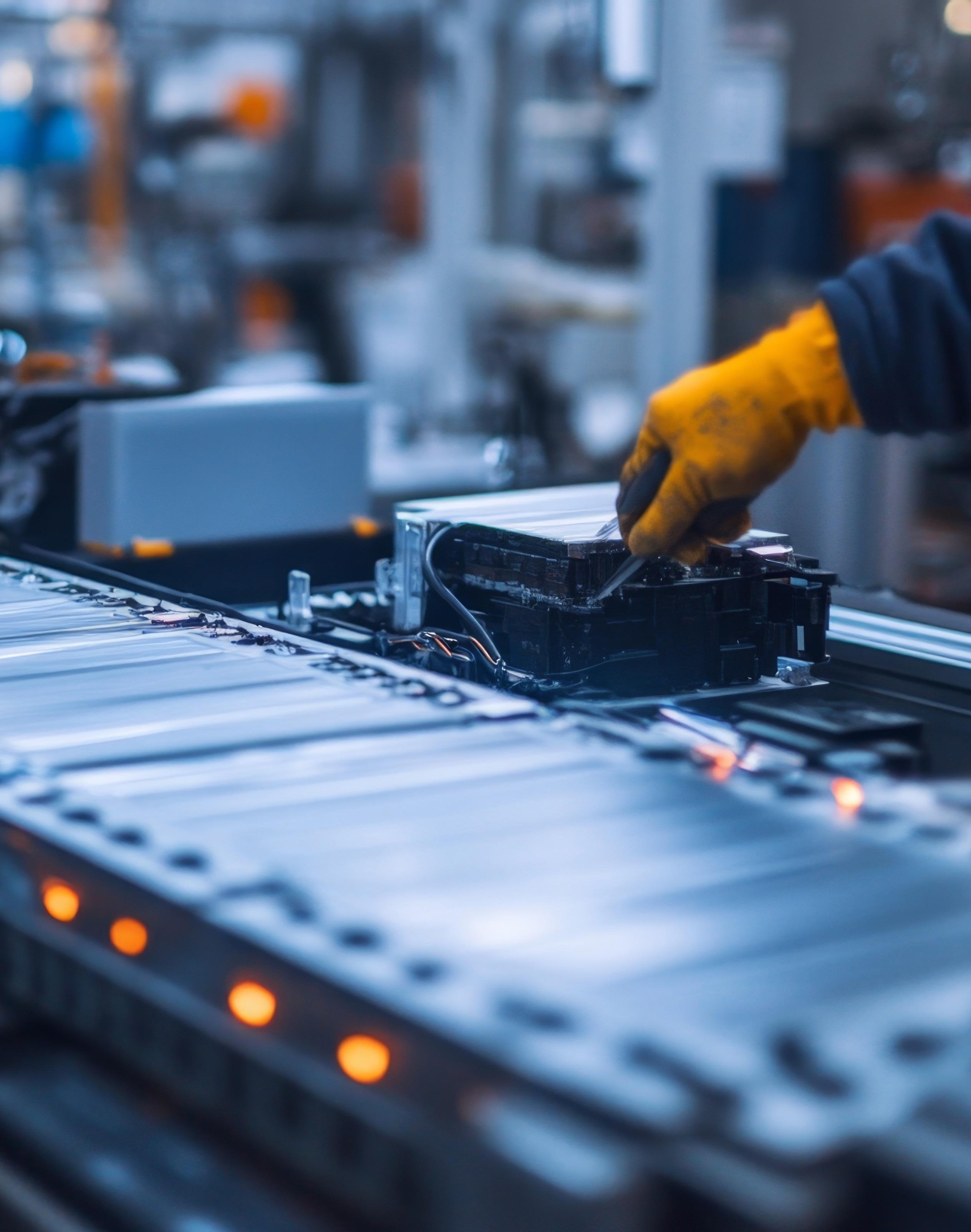

How evolving demands are driving innovations in EV battery safety
DR. CHRISTOPHER NEUMANN
Requirements for electric vehicles (EVs) are continually evolving.
With consumer expectations for longer ranges and shorter charging times increasing, it’s no wonder that battery developers are focusing on higher battery capacities (kWh), higher capacity per battery weight (kWh/kg), and faster charging solutions.
Despite significant progress in this field, challenges remain, particularly in the repeatability and standardization of testing methods. Mobility suppliers worldwide are actively addressing these challenges by refining testing procedures and developing new materials that enhance the safety of EV batteries.
In some cases, minor modifications to existing materials are sufficient. The requirements for media and temperature resistance for EV batteries are often even lower than those for applications in vehicles with internal combustion engines
ICE). In other cases, new materials and components (such as 2D thermal barrier mats, flame barrier profiles, and heat shields) are being used that are new to the automotive industry and come with new sets of requirements.
Evolving battery requirements
Although EVs experience fewer fire accidents compared to traditional combustion engine vehicles (1.2 fires per 10,000 EVs compared to 7.3 fires per 10,000 ICE vehicles), battery safety remains a priority due to the increasing energy densities and faster charging requirements. One critical concern is the risk of thermal runaway, where a single cell’s failure can trigger a chain reaction in neighboring cells, leading to a chain reaction (thermal propagation).
While new battery designs, active monitoring systems, and temperature control can mitigate these risks, the

materials used to contain these reactions are vital to enhancing vehicle safety. These include flame-retardant materials that ensure the vehicle interior is protected in the event of a thermal runaway of individual cells or the entire battery.
This is where it becomes apparent that existing methods for testing the thermal barrier properties of individual materials are insufficient, making them unreliable for characterizing these properties.
Proven and adapted test methods
As with ICE vehicles, all components and materials for EVs must meet precise specifications for basic mechanical parameters, such as hardness, tensile strength, and elongation at break. In addition, the maximum extent to which these properties may change over a certain period under normal application temperatures is typically also specified.
DIRECTOR GLOBAL MATERIAL DEVELOPMENT, DYNAMIC SEALING • FREUDENBERG SEALING TECHNOLOGIES





Several established standard test methods have not yet been used in testing elastomer and plastic-based materials in ICE vehicles, but have long been used in other industries. These methods can be transferred relatively easily to materials for e-mobility applications.
Examples of these tests are thermal conductivity at different temperatures, dielectric strength and creep resistance, and a basic flammability rating (such as UL94 V or H). Nevertheless, adaptations to these established test methods for EV applications are often necessary.
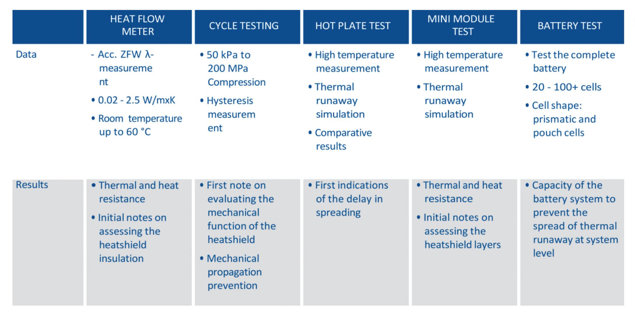
For instance, the heat flow meter and mechanical cycle testing are two tests used to characterize heat shields. Both are adaptations of existing test methods. The heat flow meter test checks thermal conductivity under different compression loads and temperatures. This allows insulation properties and heat flow between the cells to be mapped at different compression levels or phases of cell breathing and battery service life.
The cycle test is an adaptation of classic fatigue or relaxation/hysteresis measurements and provides hysteresis of compressive force during and after different load cycles with constant data recording.
Measuring a material’s dielectric strength is also a common practice. In the development of fire protection materials for busbars, the electrical properties of the material are measured after exposure to fire. This involves investigating how well a material remains insulated after a fire to prevent short circuits that could lead to further hazards.
Testing the thermal barrier properties
It’s important that new test methods are developed and standardized for material behavior during a thermal runaway. This applies to materials and components with direct and indirect exposure to flames and particles. So far, a distinction has been made between three main categories: flame contact testing, pyrotechnic testing, and heat-only testing.
Figures 2 and 3 show test complexity, safety requirements, costs, and relevance for the application increasing from left to right. The tests range from material tests and component testing to testing a complete battery.
Ultimately, the behavior of a complete battery system is directly relevant to passenger safety. So, it’s essential to test
the suitability of individual components and materials at the battery system level to meet high safety standards.
It’s also worth noting that these tests are relatively new to the automotive industry. Therefore, it’s not surprising that both the tests and specific test conditions vary considerably depending on the manufacturer, battery technology, and design, and are still being optimized.
Tests with flames and cold particles.
The torch test, torch & grit test (TaG), and pyrotechnical test are particularly significant for developing materials with direct exposure to flames or flame and particles. In the torch test, a defined flame (1,000° to 1,500° C) is aimed directly at the sample to evaluate a material’s flame and temperature resistance depending on its thickness. The TaG test supplements this with a cyclic change between flame and blasting with defined, cold particles. The most important result of both tests is the burn-through time for relative material evaluation. Almost all test providers also measure a temperature curve.
Experts in the field have carried out extensive torch and TaG tests, both internal and with various external test
FIGURE 2. The functional tests of materials with direct flame contact and with or without particle contact.




3. The functional test of heat protection materials without direct exposure to flames or hot particles.
providers, for numerous materials. While advancements in measurement methods have been made, results still show some variability in burn-through times, with occasional deviations in repeatability and maximum values.
The temperature curve would provide a deeper understanding of the different phases of material changes and degradation processes. Unfortunately, no current test method or test facility with sufficient repeatability can be used beyond comparative tests to support the formulation and development of material composition. This is due to different, nonstandardized test procedures and setups.
Examples are the various methods and locations of temperature measurement, differences in sample holders and the “flamed” sample cutouts, and the type of detection of the burn-through of the samples.
Pyrotechnic tests. In contrast to torch and TaG tests, the pyrotechnic test simultaneously exposes the sample material to flames and hot particles. This is similar to the conditions created during a direct venting event of a battery.
However, as this test only lasts 20 seconds, it provides considerably less information and no temperature curves. To ensure that the fireworks are as consistent as possible, stage fireworks are used to burn relatively evenly for safety reasons.
Nevertheless, the results are not sufficiently reproducible. They fail to provide the depth and detail required for comprehensive material development. As a result, pyrotechnic tests are only suitable for obtaining quick feedback on a material’s basic fire protection properties.
Testing under heat. Materials only exposed to heat but not direct flames are often tested using hot plates or hot oven tests. Although testing materials before and after heat exposure is wellestablished, temperatures (ranging from 400° to 800° C) are considerably higher than those typically encountered in the automotive industry. When the preheated oven is opened to load the sample, the temperature inevitably drops, and not all ovens can regain the required test temperature within the limited timeframe.
Additionally, the positioning of the sample (whether on a grate or a solid metal surface) affects the results as it
alters the heat transfer rate into the material. The hot plate test is crucial for evaluating components inside and outside the battery that are not directly exposed to open flames.
Both new test methods and new materials are still under development and need further improvement in terms of their properties and reliability, presenting a challenge and an opportunity for the automotive industry.
In conclusion, the ongoing development of EVs requires new materials and test methods that meet increasing industry requirements. Although significant progress has already been made, there is still room for improvement in test repeatability and standardization. The development of safe and efficient flame-retardant materials is crucial to the success of electromobility.
Through continuous research and development, the mobility industry can ensure that the batteries of the next generation will not only be more powerful but also safer. EV
FIGURE



extend the lifespan of EV batteries How electrolyte additives can
RAKESH KUMAR, PHD • CONTRIBUTOR
Electrolyte additives can support the life of electric vehicle (EV) batteries by stabilizing the electrode-electrolyte interfaces and mitigating the adverse side reactions that cause battery degradation over time.
One way electrolyte additives help is by facilitating the formation of a stable solid electrolyte interphase (SEI) layer on the anode’s surface. This layer is significant because it keeps the anode safe from constant reactions with the electrolyte, which can use up lithium-ion (Li-ion) and cause the capacity to drop. A well-formed SEI layer is electrically insulating but allows for the efficient transport of Li-ions.
Similarly, electrolyte additives can contribute to the formation of a stable cathode electrolyte interface (CEI) layer on the cathode’s surface. The CEI layer helps to prevent the dissolution of transition metal ions from the cathode material. It also reduces parasitic reactions between the cathode and the electrolyte, especially at high operating voltages.
How VC improves sodium-ion battery capacitance
Vinylene carbonate (VC) is a common electrolyte additive used in EV batteries, which forms a stable SEI layer on the anode. This layer protects the anode from continuous electrolyte decomposition and allows efficient Li-ion transport. VCs can be more flexible, which is beneficial for anodes that experience volume changes during charging and discharging.
Figure 1 illustrates the effect of VC on the electrochemical performance of sodium-ion TiO2 nanosheet anodes. It compares the performance of the electrolyte additive before and after cycling.
The bar graphs (a-d) illustrate how capacitive and diffusion-controlled contributions to the electrochemical processes change before and after cycling at different scan rates (from 0.1 to 10 mV/s).
Before cycling, at the lowest scan rate (0.1 mV/s), the capacitive contribution increases from 30% without VC to 51% with VC. In the same way, after cycling,
the capacitive contribution goes from 8% without VC to 63% with VC at the slowest scan rate, showing a significant improvement in the stability and reactions on the electrode surface.
Graphs (e–f) show cyclic voltammograms (CV) with a scan rate of 1 mV/s. They clearly show the capacitive (shaded area) and total current contributions after cycling, highlighting the changes from adding VC. It visually shows the capacitive contribution, revealing a higher contribution with VC (87%) than without VC (37%). This difference highlights how VC stabilizes the SEI, reduces diffusion-controlled resistance, and enables superior electrochemical performance.
VC clearly improves the performance and stability of the electrolyte in EV batteries. It does this by helping to create a stable and strong SEI layer, which leads to higher capacitive contributions, better cycle stability, and lower internal resistance.
How VC and FEC benefit Li-ions Fluoroethylene carbonate (FEC) is another common and significant electrolyte additive used in the Li-ion batteries found
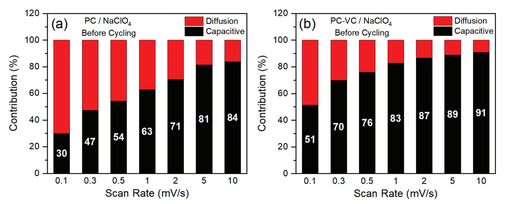
FIGURE 1.

in EVs. FEC works so well as an electrolyte additive because it breaks down more quickly in the first few cycles. It forms protective interfacial layers that stabilize the electrodes and the electrolyte, ultimately leading to a longer and more reliable lifespan for EV batteries.
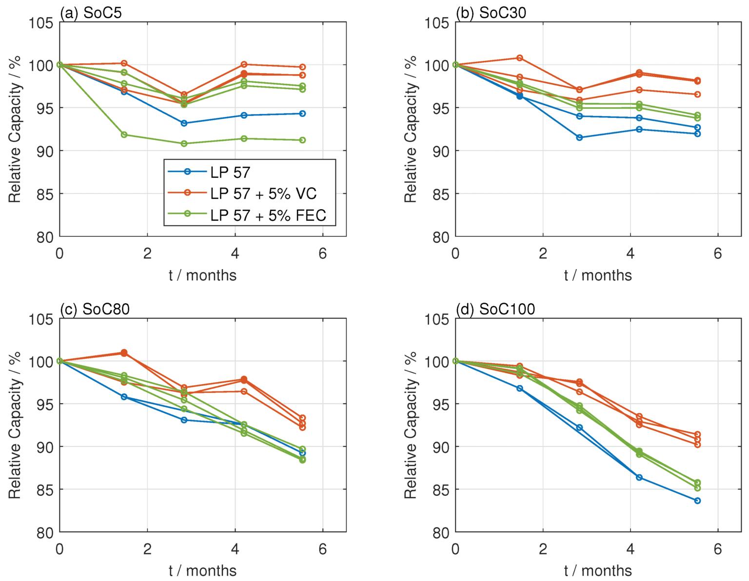
Figure 2 shows battery capacity retention under floating state-of-charge (SoC) conditions, highlighting how electrolyte additives, specifically VC and fluoroethylene carbonate (FEC), affect Liion battery lifespan over a shorter storage duration (six months).
At the lower SoC levels, capacity loss is relatively moderate, but differences emerge quickly between electrolytes.
VC additive consistently shows superior performance with minimal capacity degradation. FEC additive generally performs better than the additive-free electrolyte (LP57) at low SoCs but is less effective than VC.
At higher SoC levels, accelerated capacity fade is observed due to the stress of maintaining batteries at high-voltage levels. Batteries without additives experience the most significant degradation. VC additive improves capacity retention, clearly outperforming FEC and the additive-free electrolyte. The FEC additive also shows improvement over LP57 but performs worse than VC, which is particularly evident at 100% SoC.
VC demonstrates clear potential to enhance EV battery lifespan under stressful operating conditions where batteries are kept at high states of charge. However, FEC’s effectiveness diminishes noticeably as SoC increases, highlighting a limitation in protecting batteries in high-voltage storage scenarios.
Effect of sulfur-containing compounds in Li-ion batteries
Sulfur-containing additives generally have lower lowest unoccupied molecular orbital (LUMO) energy levels, making them more prone to electrochemical reduction than organic carbonates. This preferential reduction leads to a stable SEI film on the negative electrode.
FIGURE 1 CONTINUED. The impact of the VC additive on electrolyteelectrode interfacial stability in sodium-ion batteries. MDPI
Examples of sulfur-containing compounds used as SEI formers include 1,3-propane sultone (PS), 1,3-propanediol cyclic sulfate (PCS), prop-1-ene-1,3sultone (PES), 1,3,2-dioxathiolane-2,2dioxide (DTD), and ethylene sulfite (ES).
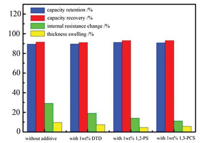
Figure 3 illustrates the influence of different electrolyte additives— specifically DTD, 1,2-PS, and 1,3-PCS (each at 1 wt%) — on battery cells’ performance and structural stability, focusing on four critical parameters.
When observed without additives, there was a high internal resistance change and noticeable thickness swelling, suggesting significant structural stress and degradation. It also had slightly lower capacity retention and recovery compared to additive-enhanced electrolytes.
With additives (DTD, 1,2-PS, 1,3PCS), improved capacity retention and recovery (approaching or reaching 100%) demonstrate enhanced battery longevity and cycling stability. Significantly reduced internal resistance changes indicate better electrode-electrolyte interfaces, lower degradation, and improved efficiency. Reduced thickness swelling implies enhanced structural integrity and less internal stress.
Specific electrolyte additives (DTD, 1,2PS, 1,3-PCS) enhance battery performance, longevity, and safety by stabilizing battery internal structures, minimizing degradation, and maintaining battery capacity.
Effect of other electrolyte additives Phosphorus atoms in polyphosphonates act as trapping agents for hydrogen radicals, a key component in combustion processes. This naturally flame-retardant quality makes fires from electrolyte
leakage or thermal runaway far less likely. Copolymers with flame-retardant phosphonate units maintain ionic conductivity (~10⁻⁵ S cm ¹) and stability in a broad electrochemical window (0.5–4.5 V vs. Li⁺/Li), and at elevated temperatures.
• The industry’s lowest DCR for greatest efficiency
• Current ratings up to 14.8 A with soft saturation
• Wide inductance range from 0.10 to 4.5 µH
• Industry-leading 80 V voltage rating — suitable for wide VIN DC-DC converters
FIGURE 2. The influence of electrolyte additives (VC and FEC) on Li-ion battery capacity retention under floating SoC storage conditions. MDPI
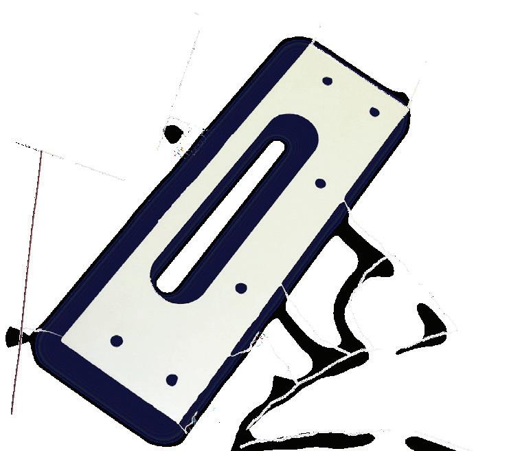
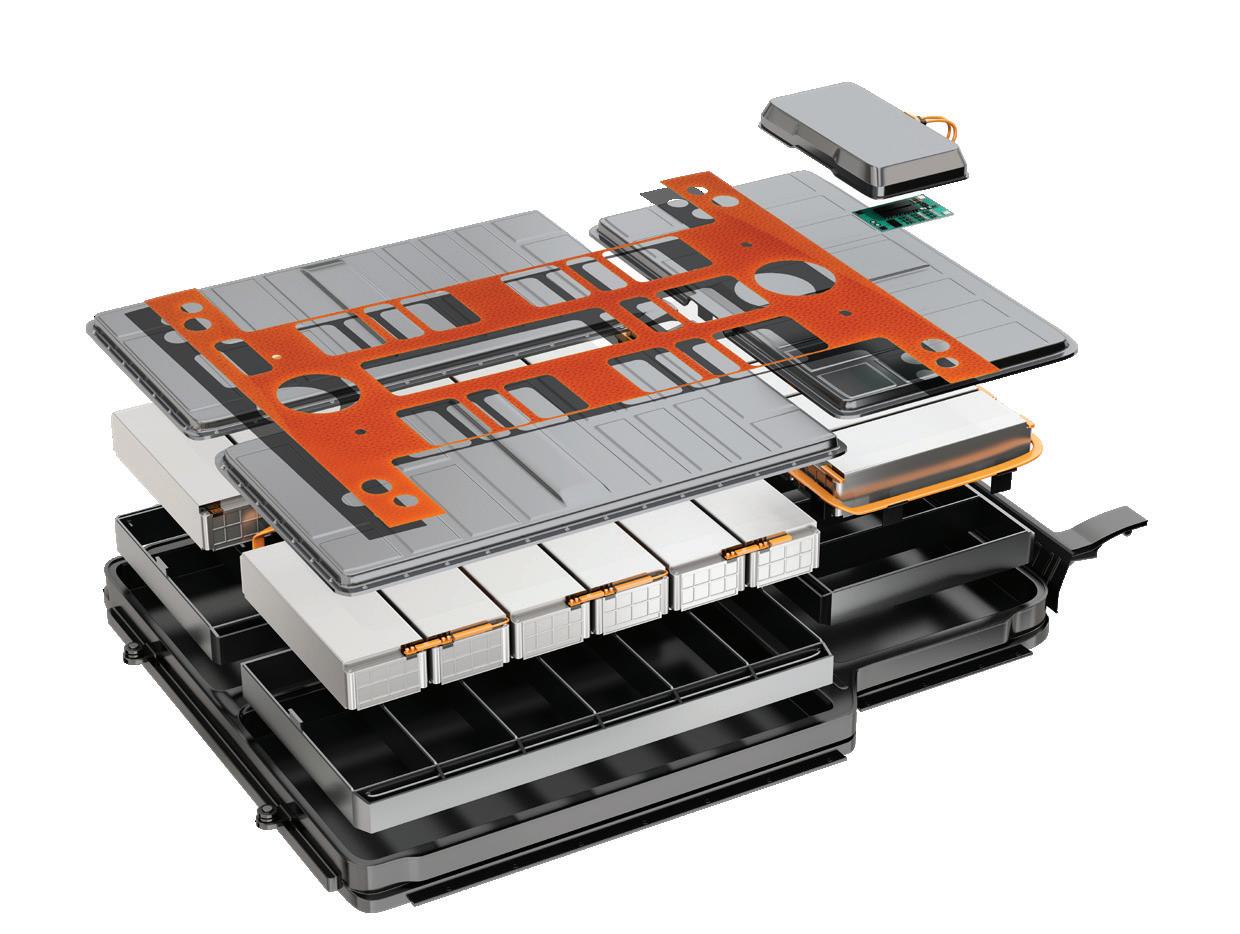
Battery Assembly Materials
Adhesive Tapes, Polymer Films, Silicone, Foam


PSA Adhesive Bonding
→ Transfer Adhesive, Double Coated Adhesive
→ Custom Die Cutting, Slitting, Sheeting
→ Polymer Film Adhesive Lamination
→ Zone Adhesive Lamination
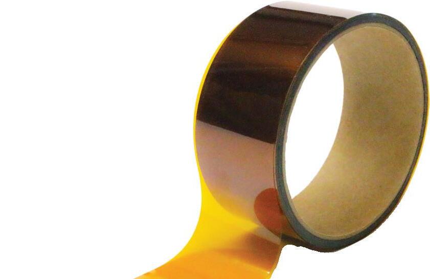
Polymer Film Insulation
→ Cell Separation
→ Dielectric Film Insulation
→ Barrier Films
→ Slot Liner Insulation
→ Wire & Cable Wrapping

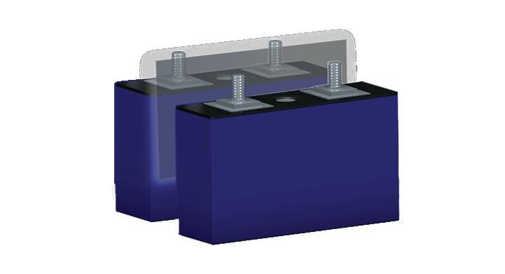
Silicone Rubber Sealing
→ Solid, Foam, Sponge Rubber
→ Adhesive Backed Silicone
→ Flame Retardant, High Temp., Thermally
Conductive, Reinforced

Lithium bis(trifluoromethanesulfonyl)imide (LiTFSI) is chemically and thermally stable with a high decomposition temperature, improving battery durability by limiting electrolyte breakdown. Dual-salt systems (e.g., LiTFSI–LiODFB) show better thermal stability than LiPF6. However, LiTFSI alone can corrode aluminum current collectors above 3.7 V. LiPO₂F₂ is another effective additive that improves cycling stability of Li-rich cathodes. By promoting a stable CEI film, it suppresses electrolyte breakdown at high voltages and reduces transition-metal dissolution (two primary cathode failure modes), leading to longer lifespan.
The disadvantages of additives
While electrolyte additives extend battery life, they also present challenges. Some degrade in storage (VC), generate excess gas or toxic byproducts (EC, PS, DTD), or raise impedance and stability issues at high voltage (PES, ES).
Despite these drawbacks, VC, FEC, and sulfurcontaining compounds remain among the most effective options for improving Li-ion and sodiumion battery performance, and ongoing research continues to refine their stability and safety. EV
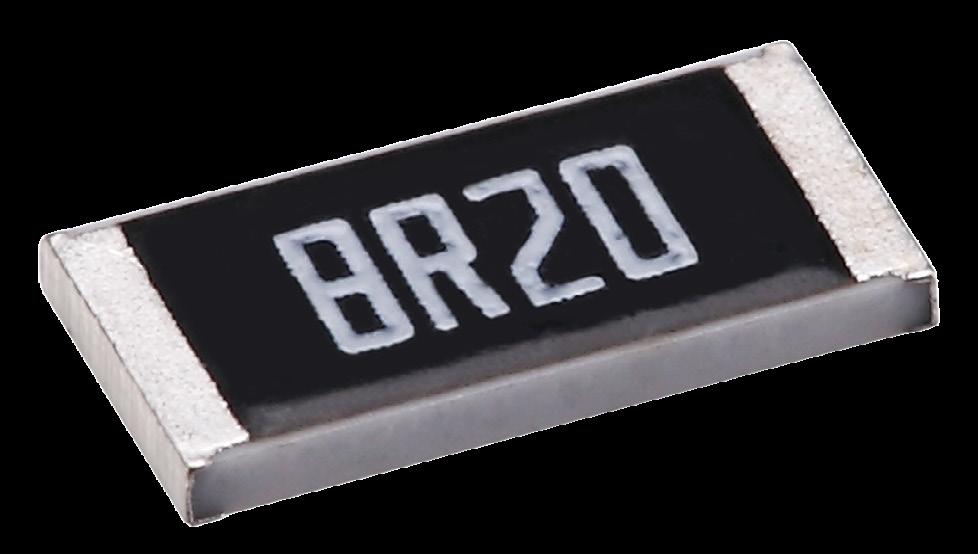
Viking Tech America Corporation is a manufacturer of passive components, including resistors, inductors, capacitors, and supercapacitors. As a global leader in thin film production, we support many ODM and OEM customers with high-reliability components that meet the highest standards such as AR..A Series
AR..A Series Benefits
• Available in sizes from 0201 to 2512.
• Tight tolerances of 0.01% to 0.1% for precision in critical designs.
• Low TCRs from 5ppm to 50ppm.
• Resistance range of 10 to 1MO.
• Suitable for applications in automotive applications, medical devices, testing equipment, and communication devices.

Viking Tech America Corporation
4 Executive Circle Ste 140 Irvine, CA 92614
+949-398-5228
sales@vikingamerica.com www.vikingamerica.com
FIGURE 3. Electrolyte additives’ (DTD, 1,2-PS, 1,3-PCS) effect on battery-cell capacity retention, recovery, internal resistance, and thickness swelling. Wiley
