The biggest players in manufacturing convened at the ARC Industry Leadership Forum, and they were all-in on AI.




























The biggest players in manufacturing convened at the ARC Industry Leadership Forum, and they were all-in on AI.


The biggest players in manufacturing convened at the ARC Industry Leadership Forum, and they were all-in on AI.


The biggest players in manufacturing convened at the ARC Industry Leadership Forum, and they were all-in on AI.


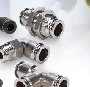





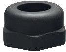
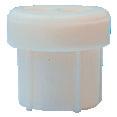
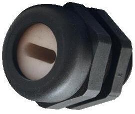
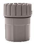
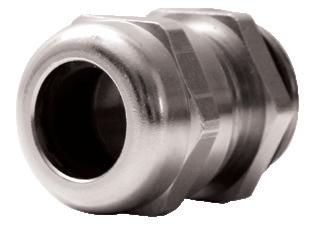
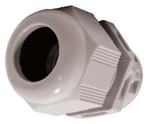
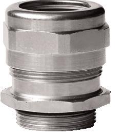
starting at $4.00/5 pk. (PLUG532)

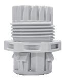
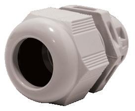
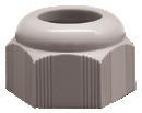
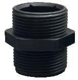
NITRA pneumatic push-to-connect fittings are easily installed and work well with flexible tubing to make sealed connections.
• Threaded connections available with NPT, G-thread, and BSPT R-thread types
• Union-style fittings
• Available in thermoplastic, nickel-plated brass, or stainless steel bodies


starting at $23.00 (7001000100U)





Metal Work is a trusted name in pneumatic components, and we now carry several valve types, including toggle and axial lever manual valves, push-pull manual valves, mechanically operated air valves (mechanical limit switch valves), pushbutton air valves, air pilot valves, and solenoid valves. Configuration and port sizes include 3-port, 3-way, 2-position, and 5-port, 4-way, 2- or 3-position valves.





• Configuration options include male straight (hex and round body), bulkhead female, long male elbow, tee reducers, and much more
• High working pressure and temperature
• Threaded elbow and tee fitting bodies can be rotated after installation
• Coils sold separately for solenoid valves in voltages from 12 VDC to 220 VAC
• Solenoid valves are available in internally and externally piloted versions
• Externally piloted valves allow a comprehensive pressure range and control pressures down to amfull vacuum



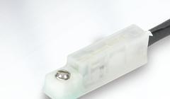
starting at $15.50 (CPS9D-AP-A)

NITRA cylinder position switches are compact purpose-built switches designed to detect the position of a cylinder.

• Electronic solid state switch output
• GMR sensing technology
• LED switch status indication
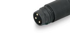
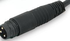
• Integral 0.15m cable with M8 snap-fit connector or 3-meter wire leads
• Come with either 45 or 90 degree cable
• 5-28 VDC operating voltage
• NEMA 6 / IP67 rating
• CE, RoHS, REACH approvals






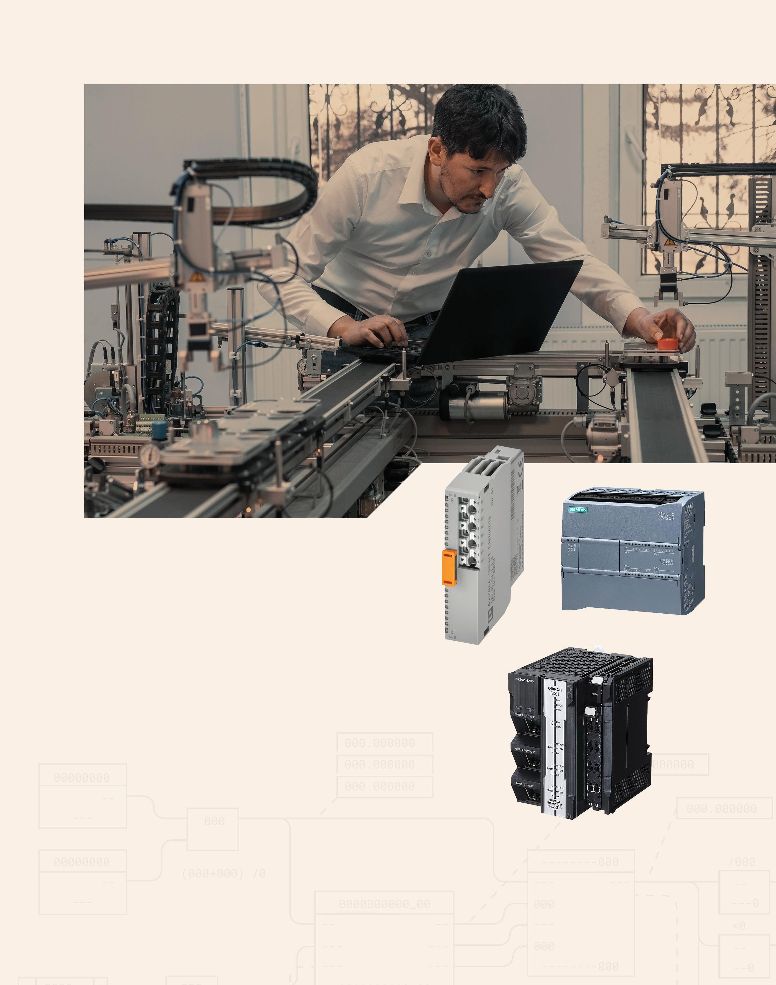
Partnerships have been a recurring theme at the industry events I’ve attended thus far this year. Many organizations understand the need for manufacturers, academia, and government to work collaboratively to understand where we’re at, where we need to go, and how to get there. Technology is catching up to fulfill our visions for the future, and the elephant in the room is driving innovation’s pace.
Everyone is concerned about the workforce gap, and many are scrambling to figure out how to increase automation, optimize human capability and performance, and entice younger workers to join their teams. And despite diminishing DEI requirements and practices nationwide, many individuals and companies still recognize the need to broaden their workforce and attract people with different perspectives.
At a recent event hosted by NextFlex and Ohio TechNet at Lorain County Community College, the speakers emphasized the workforce trend of skills-based hiring. They anticipate employers such as the U.S. Department of Defense will increasingly seek job-ready students trained in specific technologies and disciplines. In response, colleges are working closely with industries and government agencies to learn what skills they need and devise corresponding curricula, hands-on training, and certification programs to fill the gap.
“What have the last ten years taught us?” said Brynt Parmeter, chief talent management officer at the U.S. Department of Defense. “There's no single institution, no one school, company, or government agency that can do this
alone, and it takes partnerships. It takes building these ecosystems where ideas can flow and students can connect with industry mentors, where education aligns with the demands of the real world.”
But how do you get students to enroll in such programs, let alone fill the gaps? Dan Gamota, executive director of NextFlex, believes nurturing the future workforce begins well before the college years. NextFlex developed the FlexFactor program to introduce K-12 students to advanced technology and automation and has already engaged more than 6,800 students across Ohio.
“A lot of times it starts at the kitchen table. We, as parents, need to let our children know that things will change … When you go home today and you talk to your children, talk about FlexFactor, talk about how Ohio is the beginning of the resurgence of manufacturing,” said Gamota. “AI is here … Digital twin is coming … Autonomous is here … It's the ability to have individuals oversee all these operations, the technicians necessary to design them, and the engineers to help support them. There's a huge gap.”
The message is clear: talk to your kids, talk to each other, and join partnerships to expand solution sets, broaden your net, and attract more individuals who are ready to get to work. DW

Rachael Pasini
rpasini@wtwhmedia.com
linkedin.com/in/rachaelpasini
The MTB Series is a belt driven, profile rail linear actuator that has a number of sizes with some design configuration availability to meet high loads and stroke length.
MTBs are fully enclosed systems that perform at speeds up to 3000 mm per/second. With the addition of the MTB 105 linear actuator, the series now can move a static load of 7500 N and with a thrust capacity of 2750 N.

MAX
MAX

Applications:
Packaging and Assembly Automation
Cartesian Multi-axis Gantry Systems
Pick & Place Gantries
Automated Door Systems
Manufacturing Equipment Motion


Knowing
These companies represent the best and brightest, and they reflect the continued vision, integrity, and creativity of their design (and manufacturing) engineers.
We think they deserve recognition from you, too. Vote online for one or more of the companies listed through October.

EDITORIAL
VP, Editorial Director Paul J. Heney pheney@wtwhmedia.com
Editor-in-Chief Rachael Pasini rpasini@wtwhmedia.com
Managing Editor Mike Santora msantora@wtwhmedia.com
Executive Editor Lisa Eitel leitel@wtwhmedia.com
Senior Editor Miles Budimir mbudimir@wtwhmedia.com
Senior Editor Mary Gannon mgannon@wtwhmedia.com
PRINT CREATIVE SERVICES
VP, Creative Director Matthew Claney mclaney@wtwhmedia.com
Art Director Allison Washko awashko@wtwhmedia.com
AUDIENCE DEVELOPMENT
Director, Audience Growth Rick Ellis rellis@wtwhmedia.com
Audience Growth Manager Angel Tanner atanner@wtwhmedia.com

DIGITAL MARKETING
VP, Operations Virginia Goulding vgoulding@wtwhmedia.com
Digital Marketing Manager Taylor Meade tmeade@wtwhmedia.com
PRODUCTION SERVICES
Customer Service Manager Stephanie Hulett shulett@wtwhmedia.com
Customer Service Rep Tracy Powers tpowers@wtwhmedia.com
Customer Service Rep JoAnn Martin jmartin@wtwhmedia.com
Customer Service Rep Renee Massey-Linston renee@wtwhmedia.com
Customer Service Rep Trinidy Longgood tlonggood@wtwhmedia.com
DIGITAL PRODUCTION
Digital Production Manager Reggie Hall rhall@wtwhmedia.com
Digital Production Specialist Nicole Johnson njohnson@wtwhmedia.com
Digital Design Manager Samantha King sking@wtwhmedia.com
Marketing Graphic Designer Hannah Bragg hbragg@wtwhmedia.com
Digital Production Specialist Elise Ondak eondak@wtwhmedia.com
WEB DEVELOPMENT
Web Development Manager B. David Miyares dmiyares@wtwhmedia.com
Senior Digital Media Manager Patrick Curran pcurran@wtwhmedia.com
Front End Developer Melissa Annand mannand@wtwhmedia.com
Software Engineering Manager David Bozentka dbozentka@wtwhmedia.com




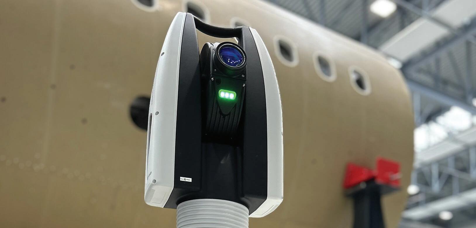
As production increases in aerospace and other large-structure industries, the need for overnight or in-process inspection is growing. Hexagon’s Manufacturing Intelligence division has introduced the Leica Absolute Tracker ATS800 designed for high-mix, large-structure manufacturing environments. This new laser tracker supports unattended scanning, realtime tracking, and subassembly alignment, with digital traceability. It is designed to assist with tasks such as fuselage integration or composite inspection without disrupting production workflows.
With ranges of up to 40 m, the ATS800 captures detailed data on features such as edges, holes, slots, and threads without physical contact or close-proximity scanning. It can be mounted in any orientation — even upside down — and deployed on AMRs, gantries, lifts, rails, and robot arms. It can
then be embedded into complex robotic workflows, enabling automated feature measurement, dynamic part tracking, and closed-loop process control in real time. Whether integrated with a fixed station lift-and-rail combination, or patrolling large assemblies on an AMR, it provides a versatile metrology solution for lights-out inspection or continuous quality assurance.
For example, the ATS800 will be powering Hexagon’s latest Presto Quality Stations, where it is combined with high-speed two-axis positioning to automate the inspection of automotive chassis features. Using long range, reflectorless scanning, multiple complex features are inspected with only single axis movement on a vertical lift or horizontal rail, reducing cycle times and increasing repeatability and throughput.
The new laser tracker includes FeatureDetect, an automatic feature recognition function that identifies
key part geometries without manual programming, helping to lower operator workload and improve efficiency in both automated and manual inspection tasks. FeatureDetect operates from CAD data or independently, using the tracker’s built in high-resolution panoramic camera. This wide aspect live image feed allows the system to recognize features directly from the physical part, accelerating setup and streamlining inspection.
The system also uses Hexagon’s TruePoint Interferometer, a measurement engine designed to reduce noise and maintain accuracy on a range of surface types and angles. For mobile applications, Hexagon’s PowerLock technology helps maintain continuous measurement by quickly reacquiring reflectors in motion. DW

While some automation solutions aim to fill workforce gaps, other solutions, such as fleet telemetry, are geared toward helping people optimize their systems and equipment. According to Steven LaFevers, VP of global emerging technology at Hyster, “Fleet managers and forklift operators are pushed to do more with less … But the right tools can make their jobs easier by helping crews to work more efficiently and get the most out of their equipment.”
Fleet telemetry in material handling refers to the use of sensors, software, and communication technology to collect, transmit, and analyze data from material handling equipment, such as forklifts, pallet jacks, and automated guided vehicles, in real time.
The Hyster Tracker telemetry solution, known as wireless monitoring, is now a standard feature on the company’s electric and internal combustion engine counterbalanced lift trucks and select stand-up lift trucks. Wireless monitoring tracks lift truck utilization, impacts, location, and diagnostic trouble codes. The technology allows operations to schedule and track preventive maintenance and better understand their total cost of fleet operations.
“The goal with making wireless monitoring standard is to equip more operations with the insights that can help them extend the life of their trucks and reduce avoidable damage, downtime, and costs,” said LaFevers.
Hyster Tracker provides real-time fleet telemetry monitoring through dashboards that visualize data. Data is stored on a cloud-based portal that can be accessed 24/7 through any internet enabled device. With wireless monitoring, operations can track utilization proficiency of operators and equipment; monitor engine, transmission, hydraulic, and electronic functions; receive safety notifications in real time; gain visibility into the location of lift trucks and operators and their activity; and see real-time impact alerts. DW
Hyster www.hyster.com
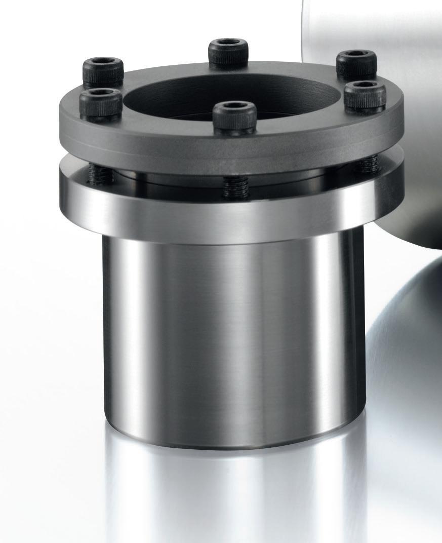
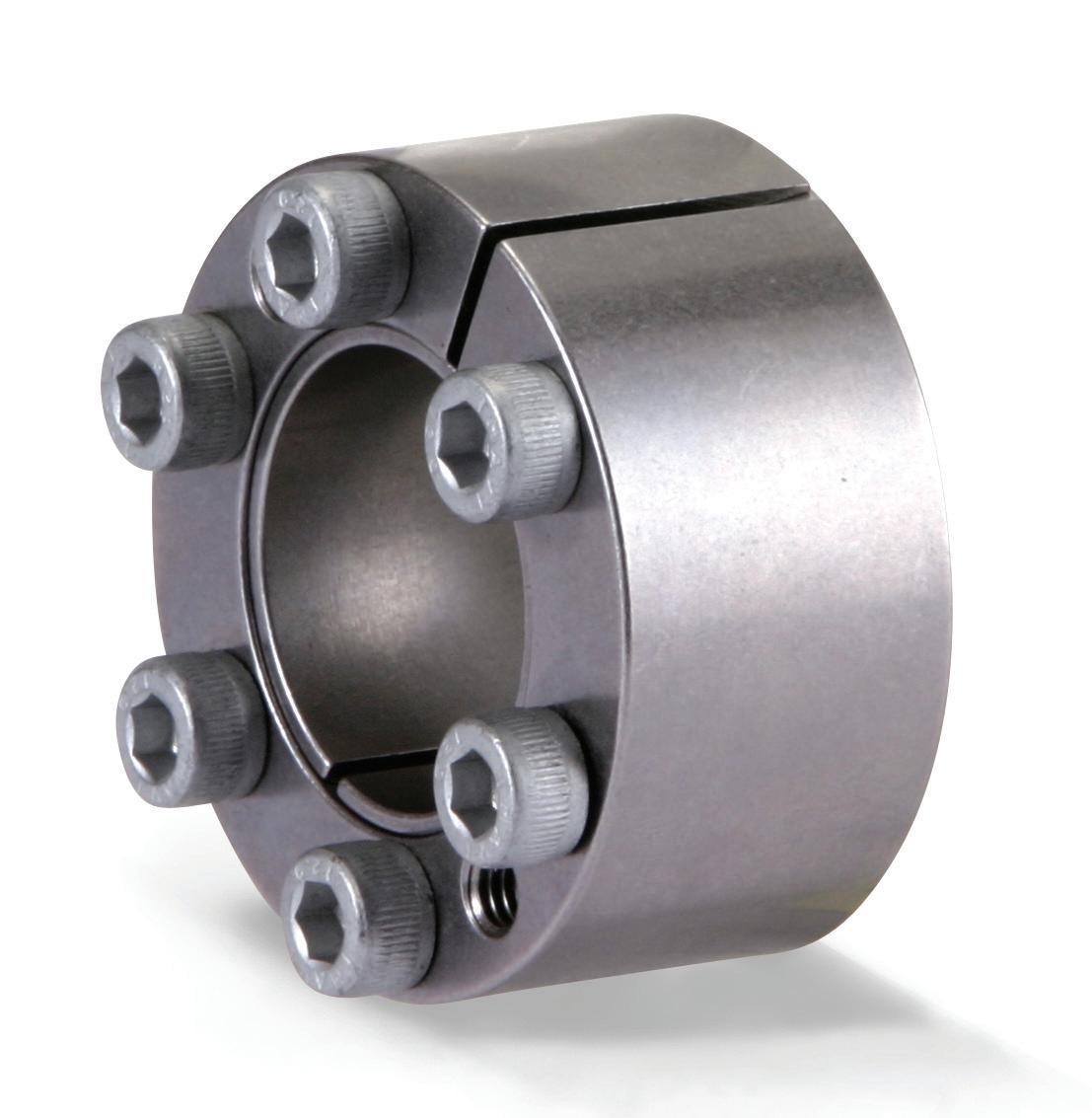
WHITTET-HIGGINS manufactures quality oriented, stocks abundantly and delivers quickly the best quality and largest array of adjustable, heavy thrust bearing, and torque load carrying retaining devices for bearing, power transmission and other industrial assemblies; and specialized tools for their careful assembly.
Visit our website–whittet-higgins.com–to peruse the many possibilities to improve your assemblies. Much technical detail delineated as well as 2D and 3D CAD models for engineering assistance. Call your local or a good distributor.

Energy density, weight, and endurance are important parameters for military applications and directly impact mission success. OEMs seek components and solutions that increase range and payload capacity without increasing weight to reduce the total system cost. Such solutions allow operators to fly longer missions while minimizing additional batteries, fuel, or equipment.
Amprius Technologies launched a new lithium-ion battery, its most energydense SiCore cell with 450 Wh/kg and 950 Wh/L. The 450 Wh/kg SiCore cell has a proprietary silicon anode material system, which the company claims delivers up to 80% more energy than conventional lithium-ion cells with graphite anodes. This enhanced
energy density translates to extended flight time, greater range, and improved system-level performance within a compact, lightweight design.
Engineers designed the new cell for extreme conditions across wide temperature ranges and mission-critical environments to meet aviation and defense application requirements. It is suitable for high-altitude platform stations (HAPS), medium-altitude platform stations (MAPS), and uncrewed aerial vehicles (UAVs).
The company expects to begin mass production of the 450 Wh/kg SiCore in the near term through its global manufacturing partners. It is currently under evaluation with plans to advance into qualification with leading aviation and defense customers preparing for
commercial deployment. This quarter, the company expects to achieve UN38.3 certification, which is required for the safe air transport of lithium-ion batteries, allowing Amprius to begin volume shipments shortly afterward.
Amprius introduced its SiCore platform in January 2024, debuting its silicon anode cells engineered for high energy and power in a single format. With the latest 450 Wh/kg cell, the company aims to support high-demand applications across electric aviation, defense, and mobility markets. DW
Amprius www.amprius.com
Precision machining is crucial for developing superiorquality products and systems, necessitating technology solutions with advanced hardware and software. Siemens introduced the Sinumerik Machine Tool Robot (MTR) with an intelligent control system that enables industrial robots to function like machine tools. The new technology enables precise path applications, including machining hard materials such as steel, which require higher cutting forces and damping. The Sinumerik MTR is suitable for aerospace, defense, automotive, and other high-precision robotic applications, such as postprocessing 3D-printed metal parts. It is also suitable for applications without process forces, such as waterjet and laser cutting.

The new industrial robot is controlled by Sinumerik One, Siemens’ digital-native CNC, which includes a digital twin for simulating and testing workflows in a virtual environment. Sinumerik One is also part of Siemens Xcelerator, the company’s open digital business platform.
The first partners to integrate the MTR into their robots are Autonox and Danobat. Numerous industries worldwise use Autonox’s robots as machining solutions using dedicated CNC robotic mechanisms. Danobat is an international consortium that offers MTR robots with payload capacities from 220 kg and a 2.6-m reach to 520 kg with a 3.6-m reach. These robots combine the accuracy and stability of a machine tool with the agility and flexibility of a six-axis robot, creating new manufacturing opportunities for industries such as aerospace, e-mobility, and energy.
The Sinumerik MTR expands Siemens’ Sinumerik Run MyRobot/ Direct Control solution with new functions and robot types. Run MyRobot integrates robots into Sinumerik CNC controls, aiming to improve precision and productivity without putting extra onus on the machinist. The idea is to expand a machine’s capability by integrating robots for more autonomous manufacturing. DW

• EDITED BY MIKE SANTORA
The biggest players in manufacturing convened at the ARC Industry Leadership Forum, and they were all-in on AI.
There is a lingering sentiment among the manufacturing community that the trends towards AI, digitalization and digital transformation (collectively referred to as Industry 5.0) are nothing more than marketing hype designed to sell new products and software.
Nothing could be further from the truth.
Granted, any new trend will always have an element of bandwagon business from marginal players and hype-riders looking to benefit from the latest trends.
One of the best ways to distinguish between an over-hyped trend and something with substance is to watch who is watching it. A great place to see that in action was at the recent ARC Industry Leadership Forum, which took place in Orlando, Fla. February 10-13.
This year’s event was almost entirely focused on AI, digital transformation and Industry 5.0 in manufacturing. It attracted more than 600 attendees representing some of the biggest companies in the manufacturing sector.
Indeed, the top 30 of these attending companies with publicly available financial numbers had a combined 2023 market cap of $4.22 trillion. If this market cap were a country, it would
rank as the 4th largest economy in the world, just behind Germany ($4.5 trillion GDP) and ahead of Japan ($4.20 trillion GDP). Most of these companies were users undergoing significant digital transformation initiatives.
The fact that these industrial heavyweights are already fully invested in implementing AI and digital strategies shows the scale of the opportunity, and the huge strategic risk of ignoring it— we’re talking Blockbuster Video-level strategic risk.
But the question remains: where do you begin, especially if you don’t have the capital and assets of these massive multinational businesses?

Siemens Electronics Factory Erlangen (GWE) in Erlangen, Germany combines Digital Twins, simulations, artificial intelligence and real production data to analyze countless scenarios and optimize material flows, reduce energy consumption, and boost productivity. Siemens
“Speed and adaptability will be the key drivers to continuing success. You need to adapt to all these challenges, which are continuously coming at you faster. If you’re standing still, you’re almost moving backwards.”
Mathias Oppelt • Siemens Digital Industries
Everywhere, all at once
In the current state of things, engineering leaders can be easily overwhelmed with all the trends and challenges thrown at them. Mathias Oppelt, vice-president of customerdriven innovation at Siemens Digital Industries (Siemens is certainly a technology vendor, but also manufactures its products using the latest smart manufacturing principles), hears about this from his customers daily and summed it up nicely during his session at the ARC Forum:
“You need to act more sustainably; you need to have higher transparency across your value chain. Have you thought about your workforce transformation yet? There’s a lot of people retiring in the next couple of years and there’s not many people coming back into the into the workforce. You still must deal with cost efficiency and all the productivity measures, while also driving energy efficiency. And don’t forget about your competition — they will still be there. And then there’s all that new technology coming up, artificial intelligence, large language models, ChatGPT — and on it goes, all of that all at once.”
Sound familiar?
Even with all these challenges, everything must now be done at speed. “Speed and adaptability will be the key drivers to continuing success. You need to adapt to all these challenges, which are continuously coming at you faster. If you’re
standing still, you’re almost moving backwards.” Oppelt said.
The answer is simple, offered Oppelt with a wry smile: just digitally transform. The crowd, sensing his sarcasm, responded with nervous laughter. It was funny, but everyone understood it was also scary, because no one really knows where to start.
Bite the bullet, but take small bites
“The continuous improvement engineers out there know how risky it can be to bite off more than the organization can chew or to try to drive more change than it can manage,” said Doug Warren, senior vice president of the Monitoring and Control business for Aveva, a major industrial software developer based in Cambridge, U.K.
“It helps to take bite-sized pieces, and maybe even use the first bite to drive some incremental benefit or revenue to fund the next bite and then the next bite. You can sort of see this this self funding approach emerge, assuming the business objectives and the metrics tied to those business objectives show results.”
Warren is puzzled by how slow a number of industrial segments have been to fully embrace digitalization and digital transformation, saying that “…it seems like everyone has at least dipped a toe or a foot into the water,” but the number of organizations that are doing it at scale across the whole

Trade deals making you reassess suppliers worldwide? You don’t have to pay for rising imports and overseas shipping at questionable ports. Interpower cords are made in and shipped from the U.S. heartland where traditional values and work ethics still prevail. Interpower cord sets provide the correct amperages and voltages so reconfiguration is not needed out of the box. Cords are tested at every stage of their manufacture. 1-week U.S. lead times, and same-day shipping on stocked products.
Toll-Free Phone: (800) 662-2290
E-mail: info@interpower.com
Business Hours: 7 a.m.–5 p.m. CST Order Online! www.interpower.com ®

enterprise is lower than most people would guess.
“The level of technological advancement doesn’t come as a big surprise, and where we go from here won’t be a big surprise. The trick will be how fast you get past the proof-of-concept and into full-scale deployment,” he said.
From Warren’s perspective, if you’re not taking advantage of the digitalization process to fundamentally change the way you’re doing work, then you’re probably not getting as much value.

“To just digitize isn’t enough. How do we change those work processes? How do we inject more efficiency into work processes to take advantage of the technological advancements you are already investing in? That’s the special sauce,” he said, conceding that it’s difficult because people typically prefer routine and structure. “That’s probably got a lot to do with the lack of real speed of adoption, because you still have to overcome the way you’ve always done it.”
Warren says a good way to look at it is like a more nuanced version of the standard continuous improvement initiatives companies have been
“Continuous improvement is incremental changes over time, where digital transformation provides at least an impetus for more of a step change in the way we perform work, whatever that work
One of the main points of hesitation towards full scale implementation of digital transformation or AI initiatives is the perceived newness of it and the uncertainty or risk associated with the perception of so-called “bleeding edge”
The thing is, none of this is all that new. The concept of the neural network was developed in the 1940s and Alan Turing introduced his influential Turing
Test in 1950. The first AI programs were developed in the early 1960s. If you are a chess enthusiast, you’ve certainly played against AI opponents for the last 20 years. Most popular video games have had story lines fuelled by AI-powered non-playercharacters (NPCs) for almost as long.
What has changed over the last few decades is the amount of computing power available, the democratized access to that compute power through the cloud, and the speed provided by the latest advances in chips.
This growth of available computational power and technology can now be applied to all the improvements organizations have been trying to achieve with continuous improvement. And they are proving to be most effective when combined with the extensive knowledge found within companies.
“Industry definitely provides complexities because it’s not just AI and machine learning (ML). There’s also domain knowledge, so it’s really a hybrid approach,” said Claudia Chandra, chief product officer for Honeywell Connected Industrials based in San Francisco.
Chandra earned a Ph.D. in artificial intelligence and software engineering from UC Berkeley 25 years ago and has spent her career working with data, AI, edge platforms and analytics.
“I’m not for just AI/ML on its own. It’s really the domain knowledge that needs to be incorporated along with (AI’s) first principles. The accuracy would not be there without that combination, because data alone won’t get you there,” Chandra said.
“That tribal knowledge needs to be codified, because that gets you there faster and might complement what’s in the data. So, digitization is the precursor to AI/ML — you need
to collect the data first in order to get to AI/ML,” she said, reiterating that it must be a step-by-step process to reduce risk.
Chandra says companies that have taken these incremental steps towards digitalization and embrace the cloud or even more advanced tech such as AI/ML will find that their digital transformation is no longer a behemoth with all the pain and risk that go with it. Plus, any vendor with a good understanding of the technology will provide at least a starting point — including pre trained models — so companies don’t have to start from scratch. “But ultimately, as you train it more, as you use it more, it will get better with the data that’s specific to your company,” she said. Certainly, the success of any AI-enabled digital transformation initiative is all about the underlying data and training the AI appropriately to get the required accuracy. But it takes several steps to set the conditions for value generation: Commit to a project; start small with the right use case; and be persistent and diligent with the data. Once you get a small victory, put the value and the experience towards the next project. With such an approach, you will soon learn why AI and Industry 5.0 are here to stay—and so will your competition. DW

Tired of calculating extra costs when ordering overseas? Interpower cords and cord sets come with 1-week U.S. lead times; and sameday shipping on in-stock products. In a world where international supply chains are unreliable, and pricing changes by the week, isn’t it time for some stability? Interpower cords are thoroughly tested after each stage of manufacturing. Scheduled and blanket ordering are available to lock in your price for 1 year while having cords shipped at intervals. Why wait?
Toll-Free Phone: (800) 662-2290
E-mail: info@interpower.com
Business Hours: 7 a.m.–5 p.m. CST Order Online! www.interpower.com
• EDITED BY MIKE SANTORA

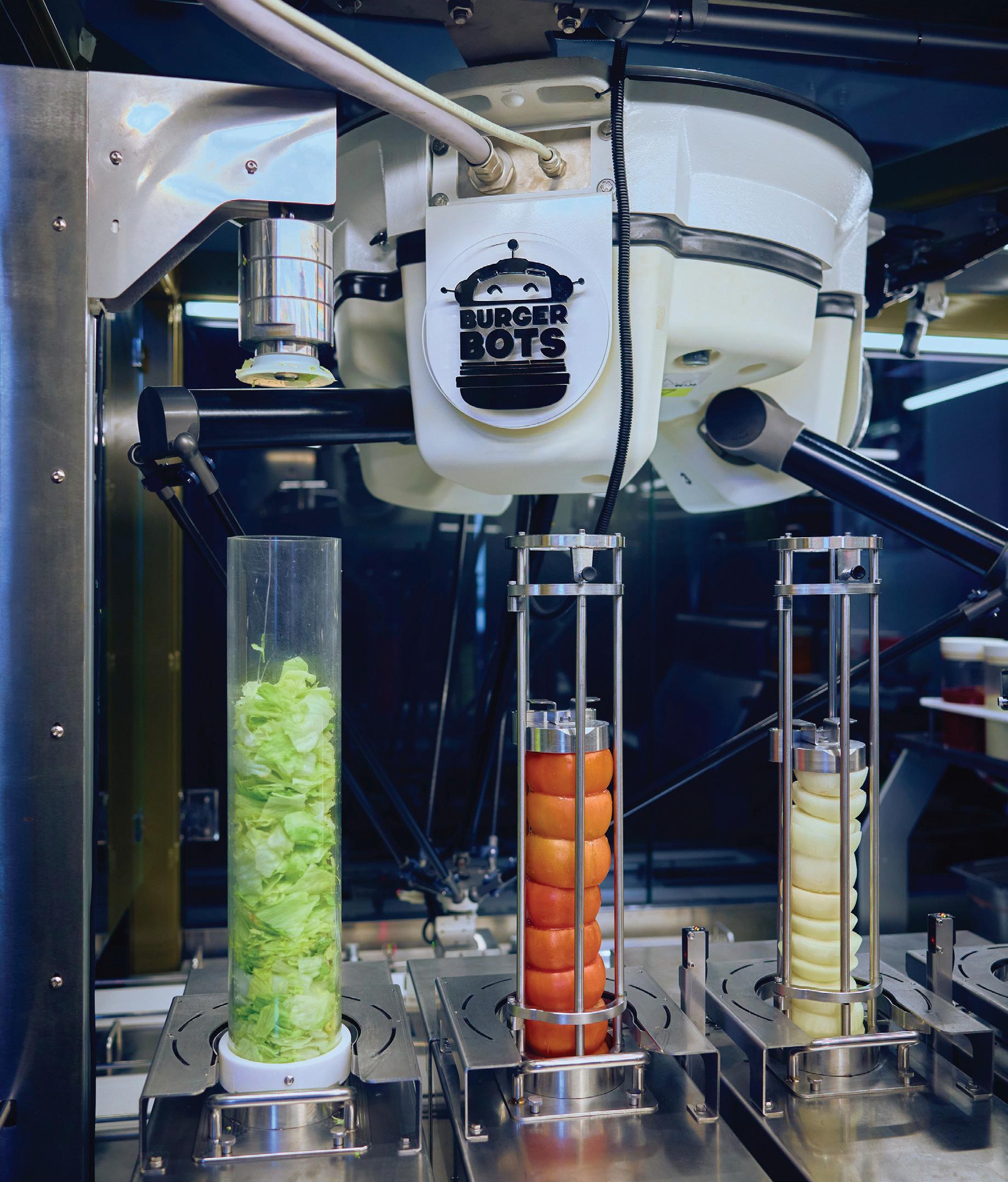
ABB Robotics is serving up the future of fast food with BurgerBots — a new restaurant concept launched in Los Gatos, California. Designed to deliver perfectly cooked, made-to-order burgers every time, the automated kitchen uses ABB’s IRB 360 FlexPicker and YuMi collaborative robot to assemble meals with precision and speed, while accurately monitoring stock levels and freeing staff to focus on customer experience.
“Integrating ABB robots with the BurgerBots restaurant concept demonstrates the incredible potential for automation beyond the factory floor,” said Marc Segura, President of ABB Robotics Division.“The food service industry is dynamic and demanding, and our technology brings industrial-grade consistency, efficiency,
and reliability to this space. When we asked the hospitality industry, 89% of managers and 73% of workers said they are open to the integration of robotics to automate tasks within their operations. By taking over repetitive and timeconsuming tasks, robots allow staff to focus on what matters most — creating memorable dining experiences.”
The compact robotic cell is a food automation first, seamlessly integrating two types of robots with an intelligent inventory monitoring system. As each order is received, a freshly cooked burger patty is placed onto a bun inside a burger box. This box is then positioned on a conveyor shuttle, which is tagged with a QR code. As it moves along the conveyor, the IRB 360 FlexPicker hygienically performs high-speed topping selection, guided
by the data stored in the QR code. Next, the YuMi steps in to collaborate on the final assembly of the burger. The entire process takes just 27 seconds per burger.
ABB’s robot controller also integrates seamlessly with non-robotic systems, enabling real-time ingredient inventory tracking — onions, tomatoes, lettuce. and condiments — ensuring smooth operations and efficient kitchen management.
One of the greatest challenges facing restaurant owners today is attracting and retaining staff. High turnover, rising labor costs, and the repetitive nature of backof-house roles continue to put pressure on hospitality businesses. Automation presents an opportunity not just to fill labor gaps, but to make foodservice jobs more sustainable and appealing


by reducing tedious tasks and improving workflows.
Supporting this shift in mindset, a recent survey commissioned by ABB Robotics found that 67% of hospitality workers agreed that robotics and automation should be used to reduce the amount of dull, dirty, dangerous work humans are doing in the hospitality industry. While 63% agreed that the idea of robotics making their job easier is exciting, 65% agreed that they would welcome robots in their workplace if it meant a safer work environment.
BurgerBots is the brainchild of entrepreneur Elizabeth Truong, who sees the Los Gatos location as the first step in a broader commercial rollout. “The vision was to bring consistency, transparency, and efficiency to food service. For restaurant owners, it means better visibility of food costs, more accurate forecasting and — ultimately — better decision making. In the next five years, I believe that most restaurants will have some form of robotic automation, whether it’s back-of-house preparation, assembly, or even front-of-house service. It will become less of a novelty and more of a necessity.”
BurgerBots is the latest in several innovations in the food service industry supported by robotic technology. ABB’s collaboration with RoboEatz on ARK — an autonomous robotic kitchen capable of preparing hundreds of meals with minimal human intervention — showcases the potential for high-efficiency, hygienic, and customizable food prep. Meanwhile, ABB is powering Makr Shakr’s robotic bartenders, that will soon be expertly mixing drinks in venues around the world. Together, these applications demonstrate how robotics is transforming hospitality with speed and consistency.
The first BurgerBots cell is now open and operating at Breaking Dawn/First Born restaurant in downtown Los Gatos, California. DW

EDITED BY MIKE SANTORA •
With ambitious renewable energy targets, Europe is undertaking a massive energy infrastructure overhaul. The EU aims to generate at least 42.5% of its energy from renewables by 2030, but some countries are aiming much higher. Germany is targeting 80% of its power from renewable sources by 2030 and 100% by 2035.
The energy transition will require significant investments in both generation and transmission infrastructure. The SuedLink project, for example, will see the construction of a 700-kilometer transmission line delivering wind-generated electricity from northern to southern Germany.
Horizontal directional drilling (HDD) equipment will be crucial for laying this new underground transmission
infrastructure, and manufacturers such as AT-Boretec are investing to ensure their equipment is ready to perform. The German manufacturer produces a complete range of HDD products, including drilling rigs, trucks, tools, and mixing and recycling systems. The MT60, the latest addition to AT-Boretec’s lineup, is the company’s largest horizontal drill rig with a drilling distance of up to 600 meters, depending on the type. With this launch, the company now offers HDD rigs in performance classes from 11 to 60 tons, with models for normal soils as well as rock.
Drilling rigs are among the more control-intensive machines in the offhighway industry. The operator must
select and carefully monitor many machine functions, from rod handling to pressure, rotation, mud pump power, and much more. The displays on these machines are the primary humanmachine interface, enabling the operator to control every aspect of the drilling process.
AT-Boretec wanted to upgrade its HDD rigs with larger displays to improve ease of use for the operator, and to better and more easily visualize the vast amount of information the machines generate. The company was also on the hunt for a new supplier due to hardware problems with the incumbent product. Operators in the field were frustrated with the display’s touch capabilities. The device’s poor responsiveness ultimately impacted productivity, as navigating

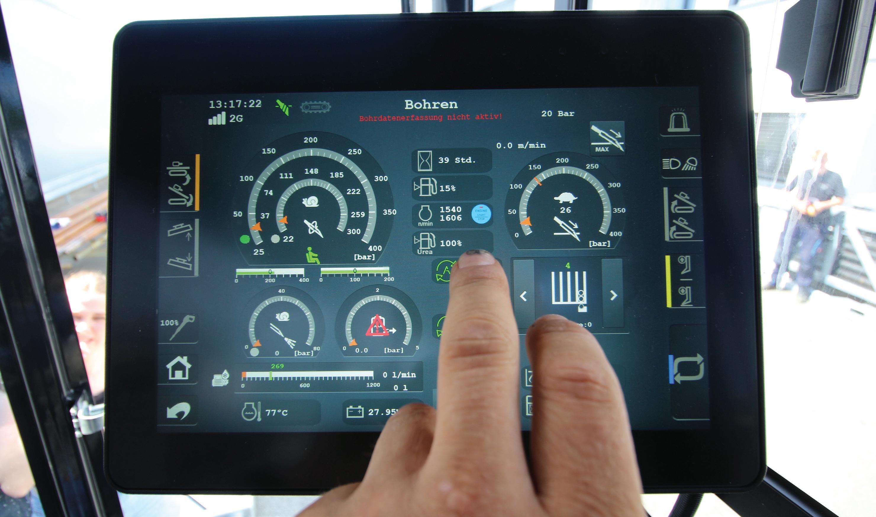
The Danfoss DM1200 display — a 12-in. fully configurable display designed for off-highway machinery.
The
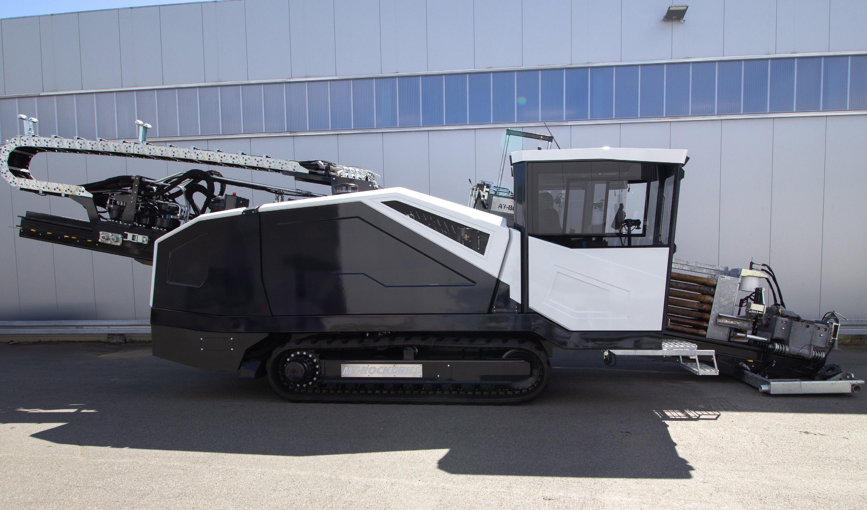
through menus and making selections took an unnecessarily long time.
The incumbent display’s touch responsiveness also lengthened commissioning time, which was compounded by challenges with the control software. AT-Boretec uses multiple types of diesel engines, electric motors, pumps, and hydraulic components in its different models, and it was a struggle to consolidate all options into a single program. This made software customization for different machine configurations a timeconsuming ordeal. In essence, a new program had to be developed for every machine that left its production line.
AT-Boretec worked with its electronics integrator partner, ProCon automatic systems GmbH & Co. KG, to evaluate potential solutions. ProCon specializes in the development and production of electronic systems for a variety of machinery, including agriculture,
construction, municipal, and forestry, and various industrial applications. ProCon recommended the Danfoss DM1200 display, a 12-in. fully configurable display designed for off-highway machinery. The DM1200 met the four application-critical criteria, which were outstanding touch responsiveness, even for operators wearing gloves; fast and reliable processing hardware to retrieve and visualize information from the CAN networks; a wide viewing angle; and a fast frame rate to display video feeds coming from the machines’ front and rear cameras.
Also standard in new machines is the Danfoss HMR CAN Rotary, which complements the touchscreen display by providing efficient screen navigation and operation of machine functions through intuitive button control. The display works together with the HMR to ensure an ergonomic operator experience.
“The decision for the DM1200 display was due to the quality and technical
features, as well as the good advice, support, and long-standing collaboration with ProCon,” said Andreas Willmes, operations development manager at AT-Boretec.
ProCon worked with AT-Boretec to design and program the display content according to their needs. Using the Danfoss PLUS+1 platform, ProCon designed new parameter-based software to enable the selection of all machine variants and options on the display, thus allowing the use of a single program across all its machines. During commissioning, technicians can select the specific engine or motor, mud pump, hydraulic system, pressure capabilities, levels of drilling rod storage, and other variables directly on the display. Today, approximately 230 parameters are selectable through the display, which effectively customizes the software to the machine and its components.
The initiative has delivered significant cost savings and efficiency improvements. Machine commissioning
time has been significantly reduced from seven or eight days, a result of the display’s touch responsiveness, speed, simplification of menus and navigation, and the PLUS+1 software.
“In the past, commissioning was a long run because you always needed to develop a new program for the display. Now, thanks to PLUS+1 software programming, you have the parameters to get everything done, and it's much, much faster,” said Kevin Herth, managing director at ProCon.
The display’s touch capabilities and viewing angle have vastly improved the operator experience. And with field-adjustable machine parameters, operators have more control over machine performance.
The Danfoss display also improved fault diagnostics, which can deliver cost savings for customers through faster, easier service and reduced downtime. Errors and faults show in clear text on the display, in addition to red lights alerting the operator to a problem. The display makes it easy for the operator to see, at a glance, what the fault is and where it’s coming from.
The overwhelmingly positive feedback from customers highlights the overall success of the project, including significant improvements in operational efficiency, user friendliness, machine performance, and cost efficiency.
“In the field, the customers really like it a lot because they have no problems with the display, even in harsh conditions such as direct sunlight. It's working flawlessly,” Herth added.
ProCon and AT-Boretec’s collaboration continues today. Development work on new options and functions is constant, with new software versions released about once a month. Herth
said the company is always bringing new ideas his way, with the next major update being the ability to display videos and images on the screen. With integrated infotainment features including a file viewer and media player, the Danfoss DM1200 remains a perfect fit for the application.
“Before the introduction of the DM1200, we faced the challenge of offering a technological advances or further development for our customers that is also scalable for us as manufacturers in the future,” Willmes remarked. “By implementing the DM1200 in our HDD drilling rigs, we have achieved a significant increase in flexibility and are well-prepared for the future regarding new projects. In collaboration with ProCon, we have succeeded excellently in this project.”
Laying thousands of kilometers of new transmission lines will be no easy task. But HDD rigs, including AT-
Boretec’s new MT60, will help ensure the work is carried out efficiently and with minimal disruption. Productivity will be key to meeting timelines, and with the help of ProCon’s engineering expertise and Danfoss’ robust components, ATBoretec has ensured its machines are up to the task and ready to help Europe accomplish its energy transition. DW
Danfoss • www.danfoss.com
• www.energy.ec.europa.eu/ topics/renewable-energy/ renewable-energy-directivetargets-and-rules/renewableenergy-targets_en
• www.www.jacobs.com/projects/ Germany-SuedLink
“By implementing the DM1200 in our HDD drilling rigs, we have achieved a significant increase in flexibility and are well-prepared for the future regarding new projects.”
Andreas Willmes • AT-Boretec

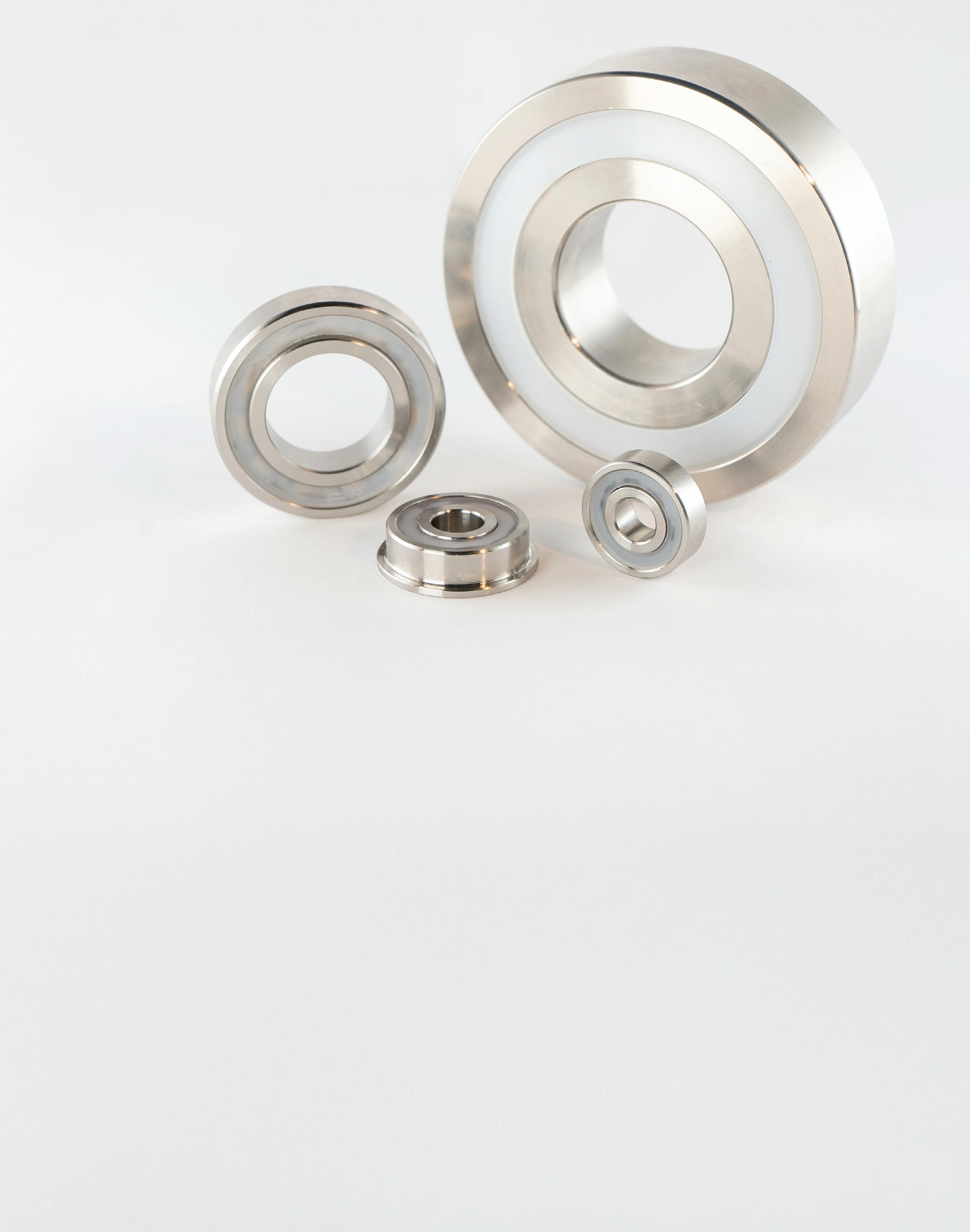
Marine grade 316 stainless steel ball bearings are available in a range of sizes, accommodating shaft diameters from 3 to 50 mm. These highquality bearings are specifically designed to excel in challenging marine environments, making them a top choice for various applications both above and below the waterline.
Chris Johnson Managing Director SMB Bearings
Knowing the causes of noise and vibration in bearings better prepares you for how to handle it, and maintain optimal ball bearing performance.
Noise and vibration in ball bearings threaten precision and safety in critical systems, costing manufacturers billions annually in maintenance and lost productivity. As demand from medical, aerospace, and industrial sectors drives the 120.98 billion USD global bearings market towards a compound annual growth rate (CAGR) of 9.5 % by 2030, tackling these challenges
has never been more urgent. Here, we explore the causes of noise and vibration and share strategies to ensure optimal ball bearing performance in critical applications.
According to the report, “An Overview of Bearing Vibration Analysis”, from Schaeffler UK Limited, increased vibration levels in bearings can have detrimental effects on machinery performance. The
report reveals that excessive vibration is a leading cause of premature bearing failure, with up to 30 % of failures linked to poor vibration management. This can lead to significant equipment damage and downtime.
Contamination is one of the most common causes of bearing noise and vibration, as even microscopic particles like dust or moisture can infiltrate a
bearing and disrupt the smooth motion of its rolling elements. This disruption creates irregularities that amplify vibrations and operational noise. Poor lubrication might worsen these issues, as insufficient or inappropriate lubrication can increase friction, heat generation, and wear in the bearing.
Misalignment of the bearing, either during installation or operation, also contributes to vibration, as uneven loads cause stress on the bearing components. Additional factors like material defects, surface roughness, or excessive preload can further degrade performance — particularly in applications requiring silent operation. Across all sectors, whether medical, aerospace, or industrial, these challenges demand a consistent approach to mitigation.
The consequences of noise and vibration are especially pronounced in industries and applications where precision and reliability are essential. Take medical imaging systems such as magnetic resonance imaging (MRI) and computed tomography (CT) scanners, for instance. Even minor vibrations can distort the images and potentially compromise the accuracy of medical diagnoses. For example, a slight vibration in an MRI scanner could blur the imaging, leading to an unclear or delayed diagnosis.
Bearings in these applications must also operate silently and in non-magnetic environments because noise interferes with sensitive diagnostic equipment and magnetic materials can disrupt the strong magnetic fields generated by MRI machines.
This necessitates the use of advanced materials, like ceramics, which are non-magnetic, lightweight, and resistant to wear. These properties ensure smooth, quiet operation and prevent interference with the imaging process, making them suitable for precision medical applications.
In the aerospace sector, bearings are subjected to extreme loads and speeds, which makes vibration control essential for safety and performance. Jet engine bearings, for example, must endure significant thermal and mechanical stress. Let’s say the engine is running at approximately 10,000 rotations per minute (rpm), with the turbine reaching temperatures of up to 1,200 °C. At the same time, the jet engine’s components are expected to support consistent balance and minimize vibration to ensure the engine performs efficiently.
Avionics systems also rely on ultraquiet bearings to avoid disrupting the accuracy of sensitive navigation and control instruments. Despite the varied applications, the same underlying principles apply; reducing vibration, managing heat, and ensuring alignment are non-negotiable.
To tackle noise and vibration, bearings need proper lubrication, precise alignment, advanced materials like ceramics, and designs resistant to contamination.
For an effective barrier against contamination, shielded or sealed bearings are a good choice; delivering an extended lifespan and maintaining consistent performance. For applications like food processing equipment, stainless steel bearings with rubber contact seals are commonly used to resist moisture and particulate ingress.
Proper lubrication also plays a vital role in damping noise and reducing wear. Advanced greases, designed for low-noise applications, can be formulated to meet the specific demands of high-speed, hightemperature or chemically challenging environments. Surgical robots, for instance, often use specialized





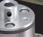






• Electromagnetic (or EM) brakes are electrically actuated but are specifically designed to halt & hold torque mechanically.
• Options to engage or disengage mechanical components.
• For high-performance demands
• Standard and modifiedstandard brakes available.
lubricants that ensure both silent operation and biocompatibility.
Next, precision in mounting and alignment is equally important. Misaligned bearings not only generate excessive noise but also suffer from uneven stress distribution, which accelerates wear. Precision mounting fixtures and alignment tools can help ensure that shafts and housing are perfectly aligned, reducing vibration and improving operational longevity.
The role of bearing design in noise and vibration control extends beyond material choice. In applications like CNC machines, where precision is critical, vibration-dampening housings can minimize the transmission of noise to surrounding structures. Bearings with non-contact seals eliminate rubbing, further reducing noise in high-speed machinery. In mining conveyors or heavy industrial equipment, split bearings
simplify maintenance while reducing the risk of misalignment, ensuring consistent performance in demanding environments.
Proactively diagnosing noise and vibration issues is another key element of an effective maintenance strategy. Tools such as accelerometers and laser vibrometers allow engineers to detect anomalies in bearing performance, enabling timely interventions. Ultrasonic detection devices, which identify highfrequency sound waves generated by faulty bearings, are particularly effective for diagnosing early-stage contamination.
In applications where precision and reliability are paramount, addressing the challenges of noise and vibration in ball bearings is a technical necessity. These issues stem from various mechanical factors, such as contamination, poor lubrication, misalignment and material defects, all of which are entirely manageable with the right combination
of preventative measures, advanced materials and proactive maintenance strategies.
By employing precision shielded or sealed bearings, choosing applicationspecific lubricants, and ensuring precise alignment during installation, engineers can significantly reduce noise and vibration while extending the lifespan of their equipment.
Whether in a medical imaging system, a jet engine or a CNC machine, the stakes are high and the margins for error are slim. The impact of bearing noise and vibration may go far beyond inconvenience but with targeted interventions, these challenges can be transformed into opportunities for improved efficiency and performance. DW SMB Bearings www.smbbearings.com

Miniaturization makes motion designs small — and in many cases, also makes them faster and more efficient.
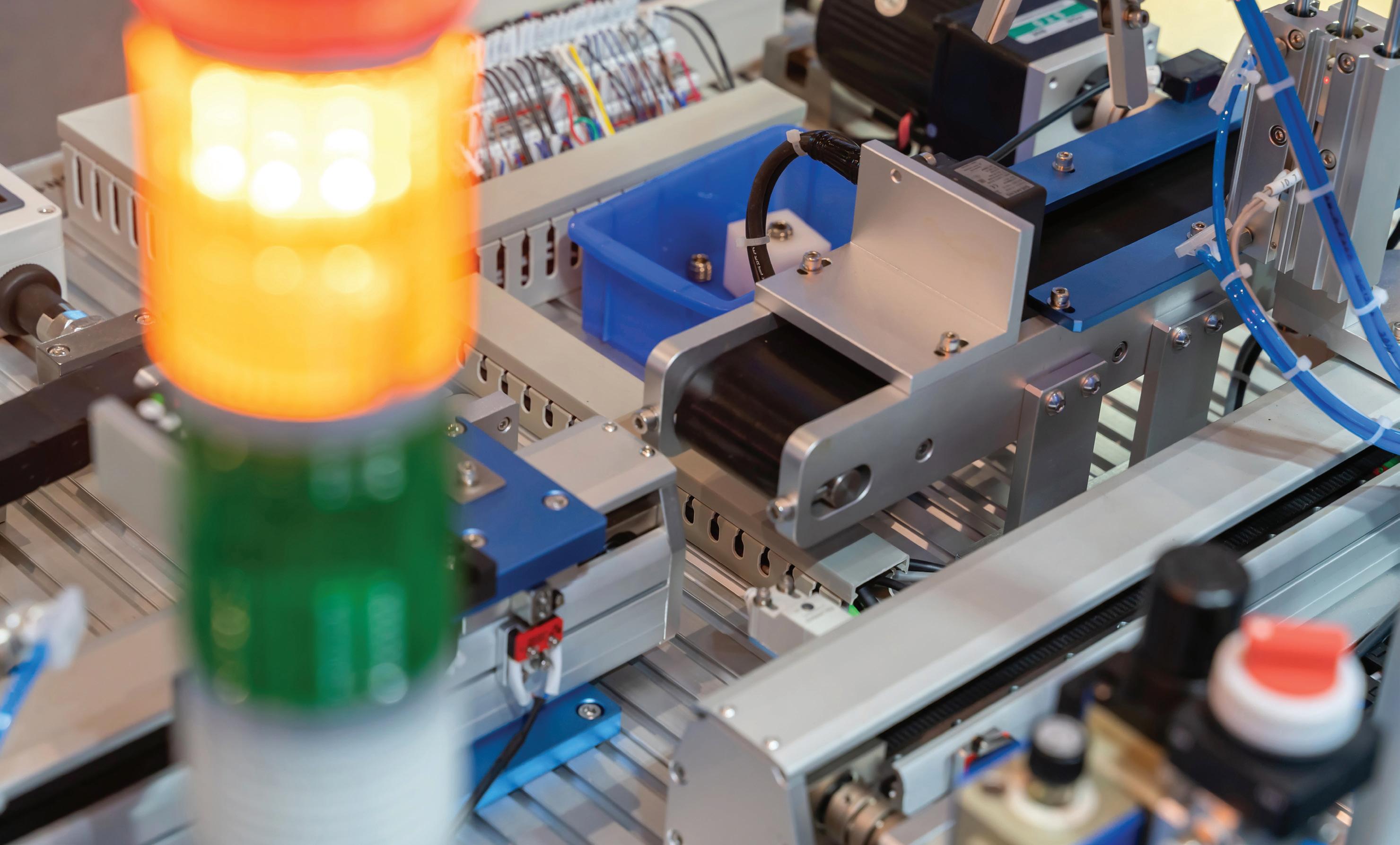
The first article in this series covered the trend of miniaturization in motion systems, especially for medical devices, aerospace designs (such as satellites), and manufacturing robotics (especially autonomous mobile variations). Miniature motors, linear actuators, and MEMS especially are enabling advancements in small-scale automation. Now, let’s consider how
miniature serial kinematics — specifically Cartesian systems — feature specialty linear components.
Considering miniature linear guides
What is the basic distinction between standard and miniature profiled-rail linear guides? It’s the width of the guide rail. Profiled rails with a width of 15 mm or
robotics include tiny cross-roller and ball-bearing linear guides (down to 3 and 2 mm across) with plastic cages and anti-cage-creep mechanisms. These are much like those in larger guides to maintain smooth and precise operation.
less (and the carriages that fit on them) are generally considered miniature by manufacturers. However, some manufacturers also produce 15-mm rail guides in standard versions.
Besides rail width, the basic construction of the carriage (or runner block) also differs. Most standard-sized carriages use four rows of balls … two on each side of the carriage. But because

of their compact dimensions, miniature versions use only two rows of balls — one row on each side of the carriage. This means that miniature profiled rail carriages have relatively lower load and moment capacities than would be expected of four-row carriages.
To help counter the loss of two ball rows, miniature guides typically use gothic arch raceway geometry, which provides four points of contact between the balls and the raceway. This ballraceway geometry gives the carriage the same load capacity in all four directions — downward, lift-off, and side loading — and provides relatively high moment load capacities.
In addition, not all miniature guides incorporate retainers to secure the balls in the carriage. That’s important to know when assembling and disassembling miniature rail and carriage assemblies.
Another difference between standard and miniature profiled rail guides concerns materials. Standard profiled rail guides and carriages are made primarily from steel, but many miniature standards come in stainless or corrosion-resistant steel for both the guide rail and carriage … and in some cases, even the balls and recirculation pieces. This is especially beneficial in applications where corrosion resistance is necessary due to handling of chemicals, occasional exposure to
water or high humidity, and industryspecific requirements for stainless-steel materials, such as those for food and packaging and medical industries.
Manufacturers also take different approaches to sealing for standard and miniature profiled rail guides and carriages. For standard versions, manufacturers often focus on ways to keep fine dust and fluid out of the carriage and to retain lubrication as efficiently as possible. Miniature components are different — they’re
often in electronics, semiconductor, and medical applications where environments are often quite clean. Sometimes they’re even in cleanrooms. So, miniature profiled rail carriages are typically offered with different sealing options and — the option to omit the seals altogether.
For those applications that require protection, some miniature guides have end-cap seals with lubrication reservoirs that protect working surfaces and reduce maintenance intervals.
Another difference is that miniature linear guides also have limited preload and accuracy class options. Because of the small size of the balls in miniature versions, preload is typically limited to 1 or 2% of the dynamic load capacity. that’s in contrast with traditionally sized linear guides allowing 8% to even 13%. Light preload or actual clearance (with slight play between carriage and rail) are most common.
Miniature profiled rails are typically offered in normal and high accuracy classes. Some manufacturers offer socalled precision variations to serve as the highest accuracy class. In contrast standard profiled rail assemblies are also offered in super-precision and ultraprecision accuracy classes.
However, there are caveats when selecting miniature linear bearings. Miniature profiled-rail linear guides must

often deliver long-term accuracy to within just a couple μm or even better in some cases. As mentioned, a lot of these slides are mere millimeters wide though strokes can range from just a few millimeters to a couple meters.
Miniature guides are engineered to deliver especially high power density. when destined for axes associated less with processing workpieces and more with the transport of items. The transport is usually into and through machines for medical and packaging designs; semiconductor manufacture; office automation; and laboratory and test and measurement.
The price-performance ratio quantifies a design’s performance level for a given price. Often, a lower price-toperformance ratio indicates a highervalue component. However, when this value is expressed as a cost-benefit ratio, the term expresses quantified performance divided by price. Then, larger values are better. For example, miniature guides on semiconductormanufacturing equipment might deliver high speed and precision for wire bonding. Here, of utmost importance is
that the machine’s inaccessible linear axes operate for thousands of strokes without relubrication. Thanks to lowfriction seal lips doing double duty, some such designs exhibit minimal lubrication consumption as well.
Plus, bottom seals on the carriage of some miniature linear components can prevent environmental particulate (such as iron shavings or dust) from entering the ball runners from below. that too can extend life. with this option, lubrication pads along with the carriage seals effectively contain the grease lubricant.
There are two other factors that make the design of many miniature guides slightly different than that of traditionally sized guides. miniature guides are less forgiving of mounting error — especially when employed in twin-rail arrangements. Also, allowable preload is limited to a few micrometers … so zero preload or even slight clearance is often suitable to extend guide life.
Ballscrews range from large-diameter screws with large leads for machine tools to screws with diameters and fine leads
for optical and medical applications. However, no industry standard classifies what screws are miniature. That said, most manufacturers designate ballscrews as miniature if they have a screw diameter smaller than 16 mm. others go ahead and include these 16mm screws in their so-called “miniature” product lines.
To further segment the range of sizes, screws with a diameter that is smaller than 6 mm are sometimes called subminiature or ultra-miniature.
To be clear, ballscrews labelled “compact” are generally those with a ball nut using internal recirculation. that makes for a smaller outer diameter. however — these compact designs are often screw products with diameters up to 25 mm — much larger than miniature ballscrews.
Miniature ballscrews can come with nuts in many of the same styles as standard ball nuts including flanged, cylindrical (also called compact or slim), or with a threaded end for easy mounting into a carriage or table. Ball recirculation can be done inside the ball nut or with external recirculation methods.

Miniature systems are common in cleanrooms, so must often satisfy the stringent requirements of such settings.
Lead accuracies and preload classes also follow the same designations regardless of the screw diameter. sizing parameters such as L10 life calculations, buckling load, and critical speed are also the same for miniature and standard ballscrews. Miniature ballscrews (just like standard versions) can be manufactured by rolling or grinding. Screw diameters below 8 mm are commonly produced by grinding … although some manufacturers offer rolled screws as small as 6 mm in diameter.
In some miniature screw sizes, the diameter of the screw is too small to accommodate an appropriately sized end bearing. So to address this, manufacturers can friction weld a large journal onto the screw end to serve as a support bearing.
Besides small diameters, miniature screws offer very fine leads. some have leads of just 0.5 mm — so every rotation of the screw produces 0.5 mm of travel. This is essential for positioning semiconductor wafers, optical equipment, and elements inside medical-dispensing equipment.
Because miniature screws use tiny balls to carry the load, the preload options are limited. With most products, a

Due to their small leads, miniature ballscrews can execute very fine movements … and in vertical applications, these small leads can prevent backdriving.
Many motors, actuators, and electromechanical systems for nanopositioning and miniature machinery are ultimately designated for specialty workcells that run in cleanrooms. Cleanroom requirements also tend to override or supersede other requirements.
The level of cleanliness of a cleanroom is determined by the number of particles of six size ranges present in a volume of air. The current and most accepted standard is ISO 14644 which defines cleanrooms on a scale from 1 to 9 with 9 being worst.
Each ISO classification has a corresponding level in the now-legacy
U.S. FS 209e level that nevertheless remains in use.
What’s tricky is that moving parts (including miniature components) tend to wear and shed particles. The other source of particles in cleanrooms is people. Of course, most motion involves some friction between sliding or rolling surfaces — whether from linear bearings, rotary bearings, or meshing gears. To minimize friction from linear guides, choose rolling contact rather than sliding contact and when possible, avoid systems with high preload.
For example, a non-preloaded miniature rail guide using two rows of recirculating balls will emit far fewer particles than a preloaded standard guide with four rows of recirculating balls. Plus, the linear guide can be left with lowfriction or even noncontact seals. DW

This miniature ballscrew from Steinmeyer allows application-specific backlash or preload and customized nut geometry. Specialty lubricants (and wipers) or lubricant-free designs are possible. Application-specific accuracy classes include those for positioning applications (P0 to P5) and transportation applications (T5 to T10).

While others race to the moon and back, the Faroe Islands space program takes a bold new step in space exploration — without ever leaving Earth.
One of the world’s largest bearing manufacturers SKF, and ocean energy developer Minesto are launching a space program to harness the Moon’s energy by leveraging the power of the tides. This space program aims to use the resources we already have right here on Earth.
“Imagine a future powered by the tides of the Moon. This unique project dares to dream big and is exploring the potential of renewable tidal energy. At SKF we are proud to be a part of this down-to-earth project that aligns with our values and our ambition to create a more sustainable world,” said Annika Ölme, CTO & SVP, Technology Development, SKF.
Over the past year, SKF and Minesto have been working on tidal energy using
tidal kites in the Atlantic Sea outside the Faroe Islands. The mission is to harness the Moon’s power for predictable and renewable energy. After its successful launch into the ocean, the tidal kite called LUNA is flying underwater, invisibly and silently harvesting energy from the Moon — no matter the weather. Today, only a few of the countries with favorable tidal current conditions are beginning to use the full potential of moon generated energy — the most predictable renewable energy source on the globe.
“For us, as a tech development company to work with a global industrial company such as SKF is both a learning experience and an inspiration,” said Martin Edlund, CEO of Minesto. “We estimate there are at least 3000 more
“Faroe Islands” out there qualifying for our space program — if they all join, moon energy could replace all coal power capacity currently under development globally.”
The established tidal energy facility — a moon energy base — will kick off the Faroe Islands Space Program, firmly grounded on Earth. The kite Luna has a rated power of 1.2 MW, enough to power 200 villas with electricity for one year. The next goal is to implement a new 200 MW tidal energy facility. This could meet 40% of the expected electricity needs in 2030, providing green electricity to the small, remote island nation’s 50,000 people and 70,000 sheep. Unlocking the power of the tides is a joint work together with power company Sev.
“Our vision is to reach 100% renewable electricity generation by 2030 and we believe that tidal power may prove to become a vital part of this journey,” said Hákun Djurhuus, CEO of the Faroese electricity company Sev. SKF was brought on board to design the bearing and sealing systems for the rudders and elevators of the kites. The SKF software system calculates, for example, bearing rating life and estimates CO2 emissions, which makes it possible to compare different solutions not only from a technical perspective but also from a sustainability point of view.
“Collaboration across industries is essential for progress. Together with Minesto, we are demonstrating how technology and innovation can drive the
transition to renewable energy,” said Annika Ölme.
By framing it as a space program (that never leaves earth), the partners aim to emphasize the importance of exploring how we can harness the Moon's energy to generate renewable energy through tidal forces — amidst a new space race where many are discussing the potential of extracting resources from space and other planets. DW
SKF • www.skf.com


• According to the International Energy Agency, 80% of global electricity currently comes from fossil fuels.
• By 2050, ocean energy could potentially provide a substantial portion of the energy mix. Ocean energy is local, renewable and tides are predictable, which makes it the perfect partner to more established renewables like wind and solar.
• Ocean energy Europe estimates that ocean energy can provide 10% of Europe’s electricity and create 400,000 skilled jobs by 2050.

Robert Davis
Senior Application Engineer — Bearings
Regal Rexnord

Exploded view of
Maintaining equipment integrity is crucial across a wide range of industries and manufacturing applications. It’s especially important to keep bearings in good working order, since they minimize friction between moving parts, allowing for smooth and efficient operation of machinery.
Reduction of friction helps conserve energy and lessens the wear and tear on components. It also enables the high speeds and heavy load capacities often required in demanding environments, ultimately ensuring productivity and longevity of the equipment.
Maintaining reliable bearing operation depends on multiple factors, including proper part selection, handling, installation, and maintenance. If you are experiencing bearing wear in your applications, it’s important to understand the types of bearing wear to determine the possible causes and how best to prevent it.
Short bearing life is most often the result of issues related to lubrication, contamination, installation, misalignment, shaft lock, or other application factors. The need for rigorous cleaning processes in certain industries also presents a significant challenge to equipment longevity and can accelerate bearing wear and tear that leads to premature failure.
Wear can occur from a single cause or from multiple causes, so be sure to consider all the possible reasons. It may take experience to correctly identify and resolve the root cause, especially when multiple types of wear are present.
This list of common types of bearing wear covers typical forms that can occur, along with frequent causes and tips for prevention.
Frosting: Also known as micro-spalling, it is a common form of wear that is typically observed in bearings over time. The frosted appearance can be due to adhesive or abrasive wear to the material surface caused by insufficient lubrication film thickness and/or fine contamination. Continued use may result in surface-initiated spalling.
• Possible causes: Inadequate lubricant properties; lubrication breakdown; ineffective relubrication; and contamination
• How to prevent it: Review lubrication selection; review re-lubrication frequency, amount and procedure; review seal selection
Surface Initiated Spalling: Metal fatigue that develops at a material surface that has worn, deformed, or been damaged. The metal flaking that occurs is a secondary form of wear due to stress concentrations at existing wear locations.
• Possible causes: Wear or debris denting; brinelling or false brinelling; inadequate lubricant properties; ineffective re-lubrication
• How to prevent it: Determine initial source of wear; refer to appropriate prevention for source of wear; review lubrication selection; review re-lubrication frequency, amount, and procedure
Fretting: This form of wear is initially an adhesive wear between two surfaces in contact (such as the inner ring bore and shaft) experiencing movement or vibration. As the surfaces wear, continued movement or vibration results in adhesive and abrasive wear. Oxidation or corrosion may occur on the worn surfaces.
• Possible causes: Vibration; minute relative movement of surfaces; excess clearance between bearing and mating components
• How to prevent it: Reduce system vibration and imbalance; review shaft and housing fit-up
Loss of Lock: Scratching, gouging, and general wear observed in the bore of an inner ring and outside diameter of a shaft are indications of loss of lock.
Often, the set screw tips will also be worn. Fretting wear can sometimes be present on the surfaces and a precursor form of wear prior to the loss of lock.
• Possible causes: Improper tightening of locking mechanism; shafting undersized, worn, or damaged; hardened or stainless shafting reducing set screw penetration or holding; frequent start stop operation
• How to prevent it: Ensure proper installation; use calibrated torque wrench; verify shaft tolerance, replace worn shafting; consider alternate locking mechanism
Misalignment: Wear present on the raceways traveling from side to side due to improper alignment at installation or machine operating characteristics. Static misalignment creates a fixed skew between the inner and outer rings. Dynamic misalignment creates a variable skew due to system imbalances.
• Possible causes: Shaft or housing misalignment; uneven mounting surfaces; frame distortion or flexure;


bent or deflecting shaft; system imbalance
• How to prevent it: Review alignment at installation; mounting surfaces should be clean and flat; replace damaged shafting; review bearing selection
Corrosion: Deterioration of material properties due to a chemical reaction. The rate and type of corrosion depends on many factors such as material, chemical, temperature, and contact method. Proper bearing selection should balance corrosion resistance with material strength, durability, sealing, and lubrication.
• Possible causes: Insufficient sealing; inadequate lubricant properties; ineffective re-lubrication; material selection
• How to prevent it: Review seal selection; shield or cover bearing to minimize contact with moisture; review lubrication and bearing selection; review re-lubrication frequency, amount and procedure
Here are some key best practices to follow that help operations identify and prevent bearing wear in industrial applications for optimized performance and life. Regular monitoring of system parameters can help identify bearing wear early.
• Regular inspection: Implement a routine inspection schedule to check for signs of wear, such as noise, vibration, and increased temperature.
• Proper lubrication: Ensure bearings are adequately lubricated with the correct type and amount of lubricant. Regularly check and replenish lubricant levels.
• Effective sealing: Use high-quality seals and replace them as needed to prevent contaminant ingress. Look for bearings with advanced sealing technology, which are especially helpful for bearings in washdown environments.
• Product selection: Choose bearings made from corrosion-resistant materials, such as stainless steel, for applications involving exposure to corrosive substances. Also look for bearings that are specifically
Sealmaster bearings from Regal Rexnord.
engineered to withstand high pressure and high temperatures for applications where those are used.
• Correct installation: Proper installation is crucial to prevent premature wear. Follow manufacturer guidelines for mounting, alignment, and preload.


• Vibration and temperature monitoring: Implement vibration monitoring systems to detect early signs of bearing damage. Also, monitor bearing temperature to identify overheating, which can indicate lubrication issues or excessive wear.
• Training: Train personnel on proper handling, installation, and maintenance procedures to minimize the risk of damage.
Understanding the causes of bearing wear and implementing preventive measures can help operations significantly extend bearing life, reduce downtime, and improve overall operational efficiency. Choosing the right bearing for the application and adhering to best practices for maintenance are essential for ensuring reliable performance and minimizing total cost of ownership. DW
Regal Rexnord • regalrexnord.com

ALSO INSIDE: The role of multiphysics simulation in next-gen electric motors
WHERE IMDS, RCMS, AND RCDS FIT INTO EV SYSTEMS
JEFF SHEPARD • CONTRIBUTOR

Insulation monitoring devices (IMDs) are used in ungrounded high-voltage applications to ensure electrical safety, prevent accidents, and ensure reliable operation by continuously monitoring insulation resistance for early fault prediction.
A residual current monitor (RCM) is the corresponding device used in grounded systems. In contrast, residual current devices (RCDs) protect against hazards such as fires or electrocution in AC-powered applications, such as electric vehicle (EV) chargers.
In EVs, IMDs ensure safety by continuously measuring the insulation resistance between the high-voltage (HV) system and the vehicle chassis. The foundational IEC standard for IMDs is IEC 61557-8, which addresses electrical safety in low-voltage distribution systems with voltages up to 1 and 1.5 kVDC.
While the standard was developed for information technology (IT) equipment in applications like data centers, the voltage limits also apply to other applications, including EV drivetrains.
The drivetrain encompasses not only the EV’s motor but also the entire high-voltage architecture that delivers and controls power from the battery to the wheels (Figure 1).
This includes:
• The HV battery pack (typically 400 or 800-V systems)
• Inverter(s) that convert DC battery power to AC for the motor
• The electric motor(s)
• Associated power electronics and cables
Since this system carries high-voltage electricity (up to 1,000 to 1,500 Vdc), insulation integrity is critical for safety and performance. A breakdown in insulation between the high-voltage (HV) system and the vehicle chassis could lead to electrical faults, shock hazards, or thermal events.
EV chargers, especially DC fast charging systems, operate at similar voltage levels and are tightly integrated with the

Coilcraft offers a wide range of voltage-rated power inductors that assure the safe, reliable operation of your designs.
Coilcraft voltage-rated inductors support applications such as high-voltage DC-DC and AC-DC power supplies, industrial and home automation controls, appliances, and automotive, including electric vehicles (EVs).
Our XEL and XGL Families of molded power inductors offer operating voltage ratings from 60 V to 120 V, and many of our
LPS and MSS Family inductors are suitable for 400-volt operation or higher.
Our new MSS1514V Series offers an 800 V rating in a 15.5 x 15.5 mm footprint, with excellent current handling and low DCR.
Learn more about operating voltage ratings for inductors and see our full line-up at www.coilcraft.com/ HighVoltage.
drivetrain’s HV system. Proper insulation and continuous monitoring across the charger and vehicle-side systems are essential for end-to-end safety and compliance with international standards.
For example, standards UL 2232 for EV chargers and IEC 61851 for EV DC fast chargers explicitly refer to IEC 61557. IEC 60204-1, which deals with the safety of electrical equipment in machines, also refers to IEC 61557.
Working principle
IMDs apply a low-voltage signal to the HV system and measure the resulting current flow through the insulation to the ground. In addition to ensuring safety, IMDs enhance system reliability.
For example, excessive voltage can damage the winding insulation and reduce the lifespan of motors. An IMD alerts operators to potentially harmful conditions, allowing the system to be shut down before a critical value is reached (Figure 2).
2. An IMD can issue a warning alarm before the critical shutdown value is reached.
Aktif Elektroteknik

In EVs, this protection is vital to the safe operation of traction motors and inverters, which are core elements of the high-voltage drivetrain. IMDs help prevent propulsion loss or thermal failure under dynamic load conditions by continuously
monitoring insulation integrity in these components.
It’s worth noting that insulation monitoring is also vital to the safe and reliable operation of marine and aerospace systems, renewable energy installations, battery energy storage systems, low-voltage industrial motors, and more.


Monitoring current RCMs are designed to protect against excessive leakage currents in grounded electrical systems. They continuously monitor the difference between the current flowing in and out of a circuit to identify leakage current.
They provide data for system monitoring, potentially triggering alarms or other actions without immediately shutting down the power. If the leakage current reaches a critical level, the RCM will trip and disconnect the circuit (Figure 3). RCMs can be designed to monitor AC or DC flows.
The primary standard for residual current monitors (RCMs) is IEC 62020, which applies to applications up to 440 VAC and rated currents not exceeding 125 A. The standard details the requirements for two types of RCMs. Type A RCMs detect AC and pulsating DC residual currents in general-purpose applications.
Type B RCMs are designed for applications with electronic loads, variable-speed drives, and other systems where smooth DC currents must be monitored. They can also monitor AC and pulsating DC currents.

Electric vehicle drivetrains operate at elevated voltages (typically between 400 and 1,500 VDC), making insulation integrity critical. Any part of the drivetrain losing insulation to the vehicle chassis could pose a severe electrical hazard or lead to vehicle malfunction.
Insulation monitoring devices (IMDs) ensure safety by constantly monitoring the resistance between HV components and the chassis ground.
IMDs are used in EVs to:
■ Continuously check that the insulation between the HV components and the vehicle chassis remains within safe resistance limits.
■ Detect early signs of degradation or fault conditions before they become dangerous.
■ Trigger alerts or system shutdowns in the event of a fault.
■ Support compliance standards, aligning with IEC 61557-8, which sets safety requirements for ungrounded low-voltage DC systems (up to 1.5 kV) — applicable to most modern EV architectures.
In summary, the HV system in an EV drivetrain is the electrical backbone that drives the vehicle, and IMDs monitor its safety in real time. Without IMDs, an undetected insulation fault in the HV drivetrain could result in serious safety risks or system failures.

In the EV charging environment — particularly AC-powered residential or workplace chargers — RCMs provide an essential layer of fault detection between the power source and the vehicle's onboard systems, enhancing overall charging safety.
An RCD, also known as a ground fault circuit interrupter (GFCI), quickly shuts off power in case of an earth fault or leakage current. It doesn’t provide any monitoring. It simply detects imbalances in the current flowing through the circuit and trips if a predetermined number of current leaks to the ground, preventing electric shock and protecting from fires.
In residential settings, RCDs are often used as standalone protection devices. In industrial and commercial applications, they can be used with RCMs to provide more reliable system operation.
IEC 60755 covers general safety requirements for RCDs, including those intended for AC systems (IEC 60755:2017) and DC systems (IEC 60755-1:2022).
RCDs are classified by their sensitivity to different types of residual currents, including:
• AC is for general-purpose use and detects sinusoidal AC residual currents.
• A for equipment with electronic components detects sinusoidal AC and pulsating DC residual currents.
• F is used with frequency-controlled speed drives and detects sinusoidal AC residual currents, pulsating DC residual currents, and smooth DC residual currents.
• B is used for specific three-phase applications, including EV chargers and solar photovoltaic systems. It detects smooth DC residual currents in addition to AC and pulsating DC.
• S has a time delay to ensure selectivity between devices and cannot be used for life protection.
Summary
IMD, RCM, and RCD support electrical safety and system reliability across many high and low-voltage applications, each governed by separate IEC standards.
In electric vehicles, IMDs are essential for monitoring insulation integrity in high-voltage drivetrains, while RCDs and RCMs enhance safety in AC-powered or grounded charging systems. These devices help prevent faults, support reliable performance, and ensure compliance with global safety requirements. EV
VIGNESH GURUSAMY • SENIOR APPLICATION ENGINEER • COMSOL, INC
Electric motors play a vital role in electrifying transportation systems. They enable vehicle operation and work as generators during regenerative braking. E-motors with high power density and efficiency enable the maximum distance to be traveled on a single charge.
Achieving high power density and efficiency in e-motors is a standard design goal. Modeling and simulation can be used to ensure that these requirements, among others, are met. Here, we’ll first briefly cover different motor types and the approaches for modeling them.
Modeling various motor types
Several types of electric motors are used in automotive applications. Radial flux motors are the most commonly used type. However, axial motors are becoming
increasingly popular since they’re compact and well-suited for in-wheel applications.
Another popular type of motor is the linear motor, which is used in transportation systems that employ magnetic levitation techniques. These three motor types can be modeled with fully coupled multiphysics modeling capabilities.
Linear motors can be effectively modeled in 2D, while 3D is more suitable when end-winding effects are of interest. Due to their geometric structure, axial motors are typically modeled in 3D. An equivalent 2D design can be modeled by rolling out the cross-section parallel to the axis of rotation. Radial flux motors can also be modeled in 2D and 3D, with the 2D model being the most common.
Some effects, such as rotor skew,
cannot be accurately reproduced in plain 2D, but 2.5D provides a good approximation. In 2.5D modeling, multiple 2D cross-sections corresponding to various skewing angles can be modeled together to achieve results similar to those of 3D modeling with only a small fraction of the computational effort.
Typically, 3D modeling is only used to capture multiphysics effects that are extremely hard to capture in 2D and to verify the accuracy of existing 2D models.
Multiphysics modeling of e-motors Electric motors operate through electromagnetic fields, mechanical forces, heat transfer, and other physical phenomena. To fully understand them, a multiphysics simulation is required.
By building finite element models incorporating multiphysics effects, performance is more closely aligned with real-world applications, and designs can be optimized early in product development.

One of the primary steps in modeling an e-motor is computing the electromagnetic fields. This computation must examine the machine’s electromagnetic torque for electrical excitation. Additionally, electromagnetic losses obtained from this type of simulation can be used with a heat transfer model to calculate the rise in temperature.
The primary effect of temperature on the electromagnetic analysis can be considered by including temperature-dependent material properties, such as linearized resistivity. This will result in a two-way coupled multiphysics model. Similarly, different multiphysics
phenomena can be modeled by coupling a wide range of relevant physics phenomena, as shown in Figure 1.
Electrothermal modeling
Modeling electromagnetic motors involves modeling the stator and rotor geometry, which includes laminated electrical steel, permanent magnets, and multiphase windings. The primary results from the electromagnetics analysis are torque, electromagnetic losses, and efficiency, which can be obtained as a function of torque and speed.
Some of the losses of interest are the eddy current losses in the permanent magnets and the iron losses in the laminated steel, a soft magnetic material with nonlinear B-H characteristics.
The eddy current losses can be computed based on the electrical conductivity of the magnets. The iron losses in steel can be computed using standard loss models, such as Steinmetz
or Bertotti, or obtained from a loss data curve that provides losses as a function of magnetic flux density and frequency.
Since many of these loss models are frequency-dependent (meaning different harmonics contribute to the loss differently), simulation data in the time domain is converted to the frequency domain using the Fast Fourier Transform (FFT).
Based on the computed loss, an electrothermal model can determine the motor’s temperature rise. The increase in temperature affects the material properties of copper windings and permanent magnets, which can be modeled as a function of temperature. This results in a fully coupled electrothermal model.
Figure 2 shows an efficiency map obtained from a fully coupled electrothermal model. It shows a reduction in peak torque with an increase in speed due to the rise in temperature of the permanent magnets. Modifying the
design to improve the efficiency at critical operating points increases the vehicle’s driving range.
Coupling electromagnetics with structural analysis
Electromagnetic forces in the air gap between the stator and the rotor can cause the stator and motor housing to vibrate, resulting in acoustic noise.
To better understand a motor’s structural and acoustic behavior, the electromagnetic stator forces can be used as an excitation in a structural mechanics model, resulting in stress and strain. The mechanical vibrations can then be coupled with pressure acoustics to determine the noise.
Figure 3 shows the von Mises stress on a stator due to electromagnetic forces and the resulting acoustic noise levels. This type of multiphysics analysis is essential for understanding an electric vehicle’s (EV’s) noise, vibration, and harshness behavior.


Partial discharge measurements for the electric motors’ long life. NOW YOU CAN FIND IT!
The standard electrical tests are not enough to identify all types of failure. Marposs’ E.D.C. partial discharge measurements allow the detection of all latent defects that could generate failures in e-motors. For your electric vehicles’ safety choose Marposs E.D.C. testing system.

The traditional transient method can be used for electromagnetic analysis when modeling highly inductive devices such as electric motors. However, using this method to compute steady-state results requires solving for multiple electrical cycles.
To simplify the computation of a steady state, the time-periodic formulation can be used instead, which solves the steadystate results directly. In this approach, the electromagnetic field is solved for all times at once, and periodicity is imposed in time. The time-periodic formulation is particularly well-suited for periodic systems with anharmonic properties. This can be because of a non-harmonic excitation or a nonlinear material property.
Apart from directly finding steady-state conditions, the time-periodic method simplifies the coupling of electromagnetics with other physics. Since the time constant of an electromagnetic model is extremely small compared to heat transfer, the traditional transient approach would need to continue the electromagnetic simulation until nominal thermal conditions have been reached. This may require many electrical cycles.
With the time-periodic approach, the fully coupled physics phenomena can be solved in one go, with the electromagnetics model solving for the time-periodic conditions and the thermal model solving for the thermal steady-state conditions. This results in a significant reduction in computation time.
To summarize, the time-periodic approach is well-suited for multiphysics problems.
E-motor design optimization
An electric motor is typically designed to meet specific performance requirements. Obtaining the design parameters that result in higher power density and efficiency is crucial for EVs, making the optimization study essential in the design process.
Different optimization methods can be used, including parameter optimization, shape optimization, and topology optimization. Each method requires defining an objective function and a set of constraints. The objectives and constraints can be defined based on a single physics or multiphysics phenomenon.


For example, you could define an objective as maximizing the average torque the motor develops while constraining the volume of permanent magnets and stress on the rotor bridge in an interior permanent magnet motor.
In parameter optimization, optimal dimensions can be determined for various motor geometry parameters (such as magnet thickness and width, back iron thickness, etc.), given a specific set of objective functions and constraints. Shape optimization finds the optimal shape of a surface or a part. Figure 4 shows how the surface of an interior magnet rotor can be optimized to minimize the torque ripple.
Ultimately, topology optimization optimizes the material distribution, enabling the reduction of weight without compromising performance.
These methods can easily incorporate objectives based on multiple physics to find an optimal design for multiphysics machines.
Designing efficient, cost-effective motors is key to improving EV range and lowering costs. Multiphysics simulation helps engineers model real-world behavior and optimize designs faster, supporting quicker, more competitive product development. EV

High Voltage
Coilcraft’s MSS1514V high-voltage power inductors are rated at 800 V, doubling the voltage capacity of comparable parts.

Scan the QR code for more
www.coilcraft.com/en-us/products/power/shieldedinductors/ferrite-drum/mss-mos/mss1514v/


mk North America displayed its shuttle system for simple pick-and-place operations. It’s capable of moving small boxes and parcels for packaging and is made possible through a collaboration between mk and Igus’ Rbtx platform. Sarah Wynn

Sarah Wynn • Senior Editor
From pick-and-place to robotic add-ons, mk North America’s design to order conveyors fit into any facility.
When it comes to conveyor systems, one size does not fit all. From the layout to the load capacity and even the material choice based on the environment, manufacturers need the ability to modify the material handling machine to meet specific needs.
Known for its customizable solutions, mk North America showcased a wide range of material handling systems for packaging at Automate 2025 in Detroit.
The company, headquartered in Bloomfield, Connecticut, displayed three adaptable offerings at the show, including a shuttle system with robotic elements, a flexible chain conveyor for medium-sized goods, and a recirculating pallet system.
“One thing we pride ourselves on is the design to order based on what the
customer needs, building out exactly the cell and system our customers want in their facility,” said Michael Zampano, mechanical project engineer at mk North America, in an interview with Packaging OEM.
To assist machine builders and manufacturers with the smooth integration of its equipment, mk North America also offers design and support services.
The company’s shuttle system is designed for simple pick-and-place operations. It’s capable of moving small boxes and parcels in packaging and e-commerce environments, and is made
possible through a collaboration between mk and Igus’ Rbtx platform.
It features mk’s flat belt conveyor feeding the shuttle, which includes the company’s LZR timing belt and an internal drive roller. From there, the box moves down a plastic modular belt conveyor, which features a streamlined design and is resistant to wear and tear.
“The beauty of this design is that it’s showing off three different material handling solutions,” said Scott Blais Jr., mk’s sales and development manager, during a live demo.
The system also offers sustainability benefits by reducing energy consumption.
“It’s an energy-efficient machine, it’s recycling air right now from the environment,” explained Blais. “As long

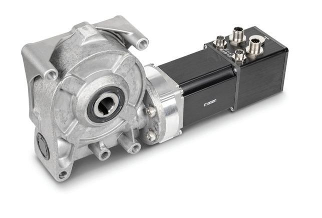

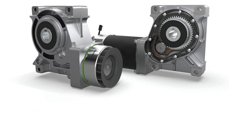


as you can power the robot, you can get the air.”


It can be integrated seamlessly into existing lines and typically takes three to four weeks to commission.
In addition, mk displayed its recirculating pallet system, the SPU 2040, which works in any application where two machines need to be combined.


Custom conveyor integration with Igus Blais noted that mk and Igus have a long-standing relationship. Through that partnership, they’re able to provide customizable conveyors with robotic capabilities.
“The beautiful part about what Rbtx and Igus are doing, in conjunction with our conveyors, is that if you’re a creative mind, or an engineering mind, the world is your oyster,” said Blais.
Also featured was mk’s VersaFlex AP10 pallet conveyor, engineered for mediumduty pallet-handling applications.
“VersaFlex is our tabletop chain conveyor system that we offer pallet systems and general conveyance for packaging, small parts, and even finished parts,” said Zampano.
It features a stop setup with singulation and lift-and-locate technology, as it can properly align with machine operations and various setups.
“This is for applications where parts are not massive, but still have a little bit of weight,” said Zampano. “This system can handle up to 60 pounds per pallet.”
“The unique thing about this is that it allows the pallets to recirculate on the underside of the conveyor and return to the operator pick station without needing a separate return conveyor for the pallet,” said Cory Santor, inside sales manager at mk North America.
It’s available in two different chain widths, which are selected based on the specific pallet size.
“This saves a lot of space in your footprint, not needing any type of return track,” said Santor. “It’s done through the use of pneumatic stops and lift and locate.”
The company said it can also be used to slash downtime in a facility.
“The operator has the chance to quickly load and go do something else, compared to asynchronous operation, where they would have to place a part each time,” said Santor. “The conveyor indexes up the position, allowing them to load and move about the facility to do other operations.”
It features easy integration, doesn’t require a PLC, and has a positioning accuracy of plus or minus 0.2 millimeters. This system tends to take about 10 weeks to commission.
6/6
• ULTEM® PEI
• Mylar®
• PVDF
• UHMW


The company showcased VersaFlex with a racetrack loop to highlight the variety of positions machine builders can utilize, along with different turn orientations.
“This is basically a turnkey system,” said Santor. “It can be brought into a facility without needing extra equipment.”
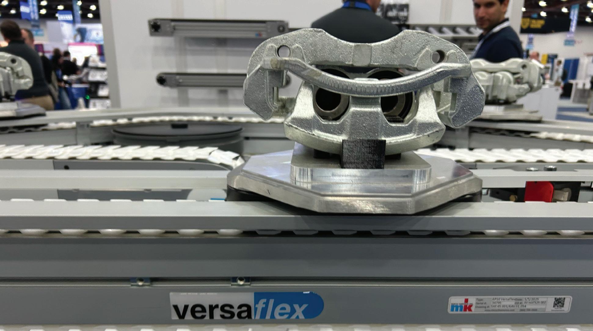
Sarah Wynn

Working with machine builders mk collaborates with machine builders and OEMs to provide the correct machine for their specific needs, and the company guides the customer to the proper solution for their project.
“When it comes to OEMs, I think we’re a fantastic partner because we have such a large breadth of product offerings. We can a la carte the solution to meet their unique machinery and equipment,” Blais said.
To keep operators updated with information about mk’s equipment, the company uses QR codes on each machine so users can access data by using their smartphones.
“There’s a QR code that brings you right to the product page on our website, including all the documentation you need for service, along with the drawings themselves and any other wiring or mk-related documents you may need,” said Zampano.
It’s part of a transformation in packaging that’s shifting the industry towards digital, including the adoption of 2D barcodes that are similar to the QR codes mk uses on its machines.
Except for the cobot on display, all mk’s equipment featured at Automate was assembled using their own aluminum extrusion profiles.
“We have a 27-year relationship with an extruder in the Northeast – very strong ties,” said Blais. “Maybe the most impressive thing is that we stock the most common 40% of those profiles and do all cutting in-house. From initial concept to shipment, everything comes right out of Connecticut.”
The company says it transforms these raw materials into fully automated assemblies, deployed in systems across North America. OEM

« Ultra-Drive belts on standard rollers move 350+ lb boxes
« Super Strong Joints are virtually unbreakable.
« Low cost, highly efficient, elastic flat belts
« High Tension Belts move heavier loads
« HEHT black belts double capacity.
l High precision Reasonable price
l Easy to install. Zero downtime.

Stephanie Neil • Editorial Director
Amcor teams up with Dassault Systèmes to create lightweight, recyclable packaging that maintains performance.

If you’ve had a sports drink or opened a pill bottle, chances are, you’ve held a plastic container designed and produced by Amcor Rigid Packaging. Chances are, too, that the plastic bottles — which Amcor produces for food, beverage, healthcare, and home and personal care products — have been designed with sustainability in mind.
Amcor, a global provider of packaging solutions for consumer and healthcare products, is focused on making packaging that is lighter weight, recyclable, and reusable. It is also committed to increasing the amount of post-consumer recycled (PCR) material in its products to meet consumer demands.
Brands face increasing pressure to adopt packaging that not only protects
and promotes products but also aligns with sustainability goals. Given shifts in consumer buying habits and minimum recycled content legislation enacted in several states – and more on the horizon –customers continue to request responsible packaging.
“Customers across all segments are looking to increase post-consumer recycled content,” said Brad Philip, principal design engineer at Amcor Rigid Packaging. “There is also a strong focus in the home care and beverage industries on reducing the weight of existing packaging. Our team has spent the past decade using advanced technology to engineer new containers. These optimized designs perform better than previous versions while using less material.”
Many times, a customer will come to Amcor with an idea to reduce materials or increase PCR in existing packaging, and it is up to Amcor’s industrial designers and engineers to turn that concept into reality.
The material redesign requires a lot of physical changes as it is up against a huge number of environmental variations, from temperature to altitude. Rather than engineering and immediately building a physical prototype, which can be time consuming and costly, Amcor uses Dassault Systèmes software to simulate the dynamic aspects of the package and anticipate how different shapes will react in the lifespan of that container.
“We design and redesign that container several times before we make that initial prototype,” Philip said.


Connecting the design landscape
Amcor has been using Dassault Systèmes Catia computer-aided design (CAD) software for a long time. And, historically, it required exporting out a file to bring it into the computer-aided engineering (CAE) software to run testing on it. It’s a good process that allows the design engineers to iterate, but when there are a dozen or more designs to test, and additional software involved, it can complicate the process.
Recently, Amcor upgraded to Dassault’s 3DExperience platform that connects processes and acts as a single version of the truth.
“We’re currently operating on the 3DExperience platform, which integrates CAD and finite element analysis simulation environments into a unified workflow,” said Philip. “With the addition of automated design iteration tools, we can now programmatically modify CAD geometry, run finite element analyses, and evaluate performance metrics in a closed-loop system. The
“With this generative approach, we’re now exploring design spaces at a vastly higher resolution. Our most recent project processed over 80 million design permutations. It’s a paradigm shift from selecting the best option among a handful of manually created models to algorithmically identifying the most efficient solution from a virtually infinite design landscape.”
BRAD PHILIP • AMCOR RIGID PACKAGING
solver interprets simulation outputs and iteratively converges on an optimal design configuration.”
TRANSMISSION-PART CONVEYING


Philip said that in the past they have manually evaluated four to twelve design variants per project. “With this generative approach, we’re now exploring design spaces at a vastly higher resolution. Our most recent project processed over 80 million design permutations. It’s a paradigm shift from selecting the best option among a handful of manually created models to algorithmically identifying the most efficient solution from a virtually infinite design landscape.”
of business consulting for the CPG and retail industries, the evolution from deploying separate design modules that weren’t integrated to a platform that brings together all the CAE applications, structural 3D design, and simulation workflows is a way to automate the process.
“And, you can leverage the computing power in the cloud to do these really robust optimization routines and generate more predictive outcomes that are going to be closer to the real physical world,” Wodar explained.
However, you still need to develop the methods and models that come from feeding historical testing data into the system in order to model the real world with better accuracy.
Warranty Against Manufacturing Defects
• Very Clean Operation
• Eliminates Tensioning Devices
• Exceptional Abrasion Resistance
In the case of a product with millions of variations, the Dassault software can run 24/7, nonstop in the cloud over the course of several days, exploring the design space to accurately know whether a design provides the performance required.
At Amcor, they’ve been conducting these kinds of tests for over 15 years, so it has been an intuitive exercise to run the software. “But we are finding ways of exploring what its capabilities are,” Philip said, noting they’ve been running these powerful tools on actual projects — and even existing products — to see if they’ve missed anything related to the optimization of the geometry on the actual container. This is a way to make sure that the newer, lightweight container can survive the palletization, the shipping, and the different physical challenges that the container will experience.
“So that’s really the advantage,” Philip said. “We can make a lightweight container that performs as well as the previous generation…It’s a new generation of design that is coming online, and we are at the forefront of that.” OEM


According to Ray Wodar, Dassault Systèmes’ director

Engineered for high-performance and durability, our heat-sealing tapes ensure a seamless release, making them perfect for a wide range of packaging applications. Tapes include skived PTFE or PTFE coated substrates due to their release properties, extreme temperature resistance, and chemical resistance.

Specialized materials include Rulon® bearing tape, a conformable self-lubricating substrate or TFL, a PTFE laminate, that has more durability and a longer cycle life compared to traditional coated PTFE materials. Different types of adhesive options are available to maximize adhesion or remove cleanly. Increase productivity and profitability by creating packaging efficiencies, such as longer production operating times, maintenance reduction and repair intervals, faster heat-sealing capability, platen protection, higher-quality seals, and lower operating costs.

KHK USA offers the broadest selection of stock metric gearing in North America. Designed for use in industrial automation applications, conveyor systems, packaging equipment, robotics, and general machinery applications, KHK’s selection of spur gears, helical gears, internal ring gears, gear racks, bevel gears, screw gears, worms & wormwheels, ratchets & pawls, gear couplings, right-angle gearboxes, and gear lubrication systems are available in various materials and sizes. KHK’s website offers free 3D CAD models for all gear products, complete product specifications, and 24/7 shopping. With KHK USA, stock gears are delivered from stock, with no minimum order or credit card surcharges.
khk usa inc.
259 Elm Place, Mineola NY 11501 516-248-3850
www.khkgears.us

CS Hyde Company 39655 N. Illinois 83 Lake Villa, IL 60046
www.cshyde.com


Nasal vaccine devices could one day be used to prevent COVID-19, avian flu, RSV, HPV, norovirus and hepatitis B.

In 2024, the FDA approved a nasal spray as the first at-home influenza vaccination, allowing adults to vaccinate themselves or someone in their care without a needle jab or a trip to the pharmacy.
Intranasal vaccines are in development for RSV, HPV, norovirus, hepatitis B and avian flu. A nasal drop vaccination for COVID-19 is already approved and in use
in India, and researchers are evaluating whether a nasal spray might be a more effective method of preventing COVID infections than those drops or the intramuscular injections that are approved in the U.S.
There have also been promising developments with antibodies or peptides delivered via nasal sprays to protect people from infections or to treat them.
To learn more about nasal vaccine devices and how they’re designed, we spoke with Aptar Pharma VP of Scientific Affairs Julie Suman, who’s been working in the nasal space for more than 20 years.
The COVID-19 pandemic “jump-started the need to consider multiple routes of vaccinations [for] multiple shots on goal,” Suman said. “We are excited about the opportunities for intranasal vaccination.”
Nasal vaccine devices have the potential to offer more convenient and more effective protection against a variety of viruses.
By Jim Hammerand • Managing Editor • Medical Design & Outsourcing

Why is there so much more attention now on nasal vaccine devices?
Suman: “One of the reasons why nasal became so attractive is the concept of mucosal immunity that would potentially limit the spread of the virus. So not only could you develop the ability to fight the infection yourself, you would not necessarily be shedding the virus and infecting others. In addition, with
COVID it’s generally thought that the virus deposits in the nose and interacts with those ACE receptors and then will translocate to the lungs, so if we can stop it in the nasal cavity the person would have a better outcome, preventing that disease from evolving into a full-blown infection.”
What exactly is mucosal immunity?
Suman: “There’s two mechanisms of
immunity. Systemic is when you get your shots, it’s circulating in the bloodstream, and different type of antibodies will fight the virus.
The nose will generate a different type of antibody that’s sitting around waiting to interact: an IgA (immunoglobulin A) antibody, versus IgG (immunoglobulin G) when you get a systemic immunization. Different types of antibodies get
generated from those routes of administration, and it’s thought that IgA — mucosal — is key for preventing the spread of infection. … There is significant immune tissue in the nasal cavity that can induce that immune response, so it has the opportunity to be used for for more than than respiratory viruses.”
How do sprays activate that response?
Suman: “Generally, the spray will deposit in the nasal cavity and interact with the lymphoid tissue in the back of the nasal cavity called the NALT (nasal-associated lymphoid tissue). There are also dendritic cells in the nasal epithelium that allow the vaccine to interact. The dendritic cells are throughout the nasal cavity and the NALTs in the back. When we administer our sprays, we want to target those regions in the nasal cavity.”
Do you need to design nasal vaccine devices specifically to hit those targets?
Suman: “We want to make sure we’re controlling the droplet size and the shape of the spray, if you will. How the person uses it can also play a role, depending on how the device operates. But generally, you want to aim the device in that target region. What we don’t want to do is aim the vaccine toward the roof of the nasal cavity. There was a case maybe 15 years ago where a component of a nasal vaccine entered the brain through the olfactory region and caused unwanted side effects, so the general school of thought is we don’t want to really hit that region of the nose with a vaccine.”
Does droplet size matter, and can you control that?
Suman: “The size of the droplets will determine whether they would deposit in the nose or the lung. If you want to deposit droplets in the lung, they have to be smaller than 5 microns. In the nose, the droplets are generally larger
than that. … In the orifice of the device, there are mechanisms for generating the droplet size so the device itself will work with the fluid to produce the different sizes of droplets. That’s a very important part of our design process and control process to make sure that we’re delivering appropriate and reproducible droplet sizes.”
Are there pediatric design considerations?
Suman: “We want to make sure that it’s comfortable for a child to use, because their noses are smaller, and some of the devices you’ll see are indicated for children and even neonates. … It depends on the shape of the nozzle itself. And an adult is going to be upright when getting a vaccine, but that might not be the case with a child. You might be cradling them. So we’ll look at things like how the orientation of your head or the child’s head may affect where the product would distribute in the nose.”

Where Precision Meets Possibility.

What’s the advantage of sprays versus droppers for nasal vaccines?
Suman: “I’m not sure that a dropper will work with Western regulations, because it’s a little more challenging to monitor the dose or control the dose with a dropper, compared to sprays that are metered so we know we’re giving a very specific volume — which equates to the dose — when we spray it. Droppers are certainly a more cost-positive solution for developing countries, but I don’t know that we’d see droppers in the Western world.”
Besides safety and efficacy, what sort of regulatory considerations are there for nasal drug delivery devices?
Suman: “There are guidelines on human factors. Can the person or the medical practitioner understand how to use the device? Can they use it correctly? We have a company in our portfolio called Noble that does human factors studies and helps produce instructions for use that our pharma companies can incorporate into their packaging and labeling. There are requirements around the materials and biocompatibility. These devices are injection molded, so there’s criterion around quality. … There are also FDA guidelines for quality control tests they want to see. We look at the shape of the spray, the size of the droplets. Certainly, dose reproducibility is No. 1. Compatibility of the formulation with the device itself is also important.”
How are nasal delivery devices sterilized?
Suman: “Everybody has a different process to sterilize a device. Some people use steam, some use gamma radiation. When we throw in a biologic or vaccine, that becomes trickier because the sterilization process can damage the molecule itself and maybe render it ineffective. The interesting thing about nasal is that from a regulatory standpoint, there is no FDA guidance that says a nasal spray must be sterile. So there’s not an obligation. However, customers may want for various reasons to have a sterile product. … Anybody who’s in this space is probably having that conversation with their pharma [customer].”

Combining conventional Swiss machining with laser processing is a cost-effective alternative to multi-operational manufacturing. This single machine platform allows Cadence to perform several processes in just one step which reduces part handling and improves its precision.
This game changing technology combines CNC machining, laser cutting, laser drilling, laser marking, and laser welding. Additional benefits include rapid prototyping, higher quality, and significant cost savings. LaserSwiss machining provides endless possibilities for new product development!


Cadence, Inc. 9 Technology Drive, Staunton, VA sales@cadenceinc.com www.cadenceinc.com
Tel: 540-248-2200 | Fax: 540-248-4400
Nitto Kohki’s DC motor-driven air compressors and vacuum pumps are ideal for applications requiring exceptionally reliable air flow, pressure or vacuum performance. Featuring oil-free operation, a single moving part, low noise, and low vibration, this line of linear air compressors comes in 12V and 24V models. Other benefits include:
• Very low power consumption
• Self-cooling design
• Exceptional service life (rated at 10,000 hours)
• Easy maintenance
Ideal for demanding applications in the medical device and laboratory equipment industry, including dialysis machines, blood separators, blood analyzers, incubators, heart assist devices and more.
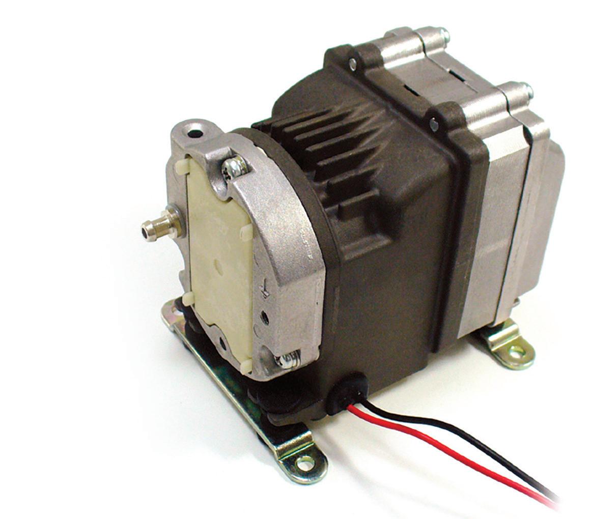
NITTO KOHKI U.S.A., INC. 46 Chancellor Drive Roselle, IL 60172
Toll Free: (800) 843 6336
Phone: (630) 924 8811
Fax: (630) 924 0808
E-mail: info-pumps@nittokohki.com www.nittokohki.com
Ryan Ashdown rashdown@wtwhmedia.com 216.316.6691
Jami Brownlee
jbrownlee@wtwhmedia.com 224.760.1055
Mary Ann Cooke mcooke@wtwhmedia.com 781.710.4659
Mike Francesconi mfrancesconi@wtwhmedia.com 630.488.9029
Jim Powers
jpowers@wtwhmedia.com 312.925.7793
Publisher Courtney Nagle cseel@wtwhmedia.com 440.523.1685
CEO
Matt Logan mlogan@wtwhmedia.com
CFO
Ken Gradman kgradman@wtwhmedia.com 773-680-5955


DESIGN WORLD does not pass judgment on subjects of controversy nor enter into dispute with or between any individuals or organizations.
DESIGN WORLD is also an independent forum for the expression of opinions relevant to industry issues. Letters to the editor and by-lined articles express the views of the author and not necessarily of the publisher or the publication. Every effort is made to provide accurate information; however, publisher assumes no responsibility for accuracy of submitted advertising and editorial information. Non-commissioned articles and news releases cannot be acknowledged. Unsolicited materials cannot be returned nor will this organization assume responsibility for their care.
DESIGN WORLD does not endorse any products, programs or services of advertisers or editorial contributors. Copyright © 2025 by WTWH Media, LLC. No part of this publication may be reproduced in any form or by any means, electronic or mechanical, or by recording, or by any information storage or retrieval system, without written permission from the publisher.
Subscription Rates: Free and controlled circulation to qualified subscribers. Non-qualified persons may subscribe at the following rates: U.S. and possessions: 1 year: $125; 2 years: $200; 3 years: $275; Canadian and foreign, 1 year: $195; only US funds are accepted. Single copies $15 each. Subscriptions are prepaid, and check or money orders only.
Subscriber Services: To order a subscription or change an address visit our website at: www.designworldonline.com
POSTMASTER:
By Mark Jones


Each month, I email this column to the editor of Design World. It is the way we communicate and the way I communicate with many others. So, an article quantifying the human mortality cost of email signatures caught my attention. I dug in, curious to find how email leads to death.
The paper, “The unexpected reason firms should institute policies to remove email signatures: Quantifying human mortality costs of email signaturebased reputation signaling” by Joshua M. Pearce, is a detailed estimation of greenhouse gas emissions caused by pronouns in an email signature. The analysis was done for Canada. The “1,000-ton rule” was used to estimate people killed, a person per year for Canadian pronouns.
I’d never heard of the 1,000-ton rule. Investigating it led to some sobering realizations and introduced me to some strange new units. The 1,000-ton rule asserts, “A future person is killed every time 1,000 tons of fossil carbon are burned.” Something I do today — burn carbon — leads to a death. Lots of assumptions go into this, not the least of which is defining death. Everyone will eventually die, and the likelihood of death increases with age. The 1,000-ton rule uses premature death. It links emissions today with someone, somewhere in the future, dying sooner than they otherwise would have had it not been for today’s emissions. It relies on estimating the number of
temperature-related deaths globally in the future, deaths that would have been delayed at 2020 temperatures. Deaths below the expected age today would be characterized as premature, a future person killed.
I made the mistake of checking my own life expectancy. Six years from now was the first answer retrieved from the internet. Not the answer I wanted. Thankfully, the Social Security Administration provides a Longevity Visualizer. It provided a more comforting 19 year estimate and provided a visualization of the skewedleft distribution of death by age. Some people die at the center of the distribution, but nearly 50% of all deaths are premature. Nearly 50% live longer than average. There is a lot of slop.
On top of the slop in the definition of a death, there is slop in the estimation of future temperatures. At best, the 1,000-ton rule is an order of magnitude or so estimate.
Every byte we send takes energy. Energy comes from burning fuels, releasing carbon. The tiny, tiny impact of a signature on an individual email, when multiplied by the number of emails bearing pronouns, becomes significant. Only 15% of Canadians put pronouns in email signatures, yet this adds up to a future death per year by application of the 1,000-ton rule.
The 1,000-ton rule is for carbon emissions. That’s 3,700 tons of CO2. Data on per capita emissions across
my lifetime indicate I’m responsible for lifetime emissions of 1,230 tons of CO2, 335 tons of carbon. I’m strangely relieved my emissions haven’t killed a future person yet. Based on my life expectancy, I will not make 1,000 tons in my lifetime. Further, all of my outgoing email activity is a near negligible part of my footprint, an email signature even less. Incoming email, dominated by mail I don’t really want and rarely read, still isn’t a big part of my personal footprint, but it is far more significant.
Pearce’s paper points out inclusion of any number of other things, like useless FAX numbers, long disclaimers and logos all come at some cost. Nearly 50% of all emails are spam. Given the numbers used by Pearce, global spam is responsible for at least 259 million tons of CO2 emissions and is going to be responsible for over 70,000 future deaths per year.
The mortality cost of email signatures reminds us that even small actions have consequences. Small things add up. Reputation signaling in email signatures feels like a strange place to start. There are so many other things wrong with the email ecosystem. If I were granted the ability to fix one thing with email, pronouns in email signatures would be pretty far down my list. Spam is a bigger target. It is a current scourge and, as the analysis of email signatures indicates, will have consequences long after it is deleted. DW


Designing efficient systems involves much more than simply understanding a few basic principles. There is a true art to balancing the specific requirements of an application in order to achieve the desired goals in the best possible way. Help us understand the unique needs of your application and together, we’ll develop something that surpasses what any of us could have done alone.
Contact your distributor to learn more, or visit clippard.com to request a free catalog and capabilities brochure.


