Design Portfolio
Willie Joe Leidolf
“The word, the right word, the apt word, it’s the opposable thumb of the mind. It is not important that I be noticed, but that my work be noticed. The engine of genius is endurance. Happiness; it’s a sales pitch. Doing right, the rock.”
-Mr. Canon
Lo-Fab
Fabrication Design
Vera Iconica
Residential Experience
Montessori
Digital Workflow
Architectural Workshop
Higher Education Experience
Orphaned Oil Wells
Master’s Thesis Bike Shelters
Faure Halvorsen Residential Experience Villa Savoye Theory Objects Modeling 01 04 05 10 11 14 15 18 19 24 25 26 27 28 29 32 33 36
Design + Build
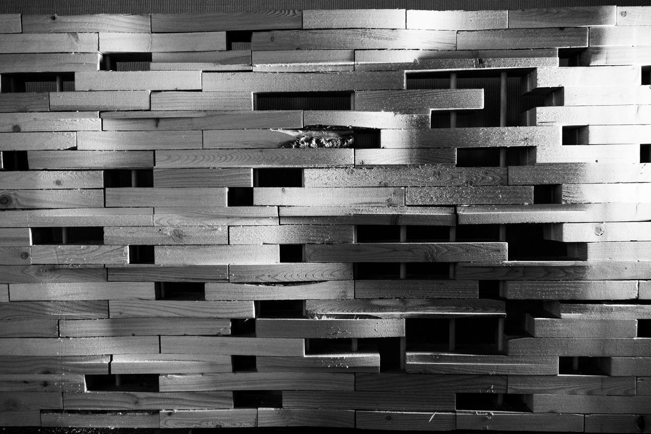
Lo-Fab Fabrication Design
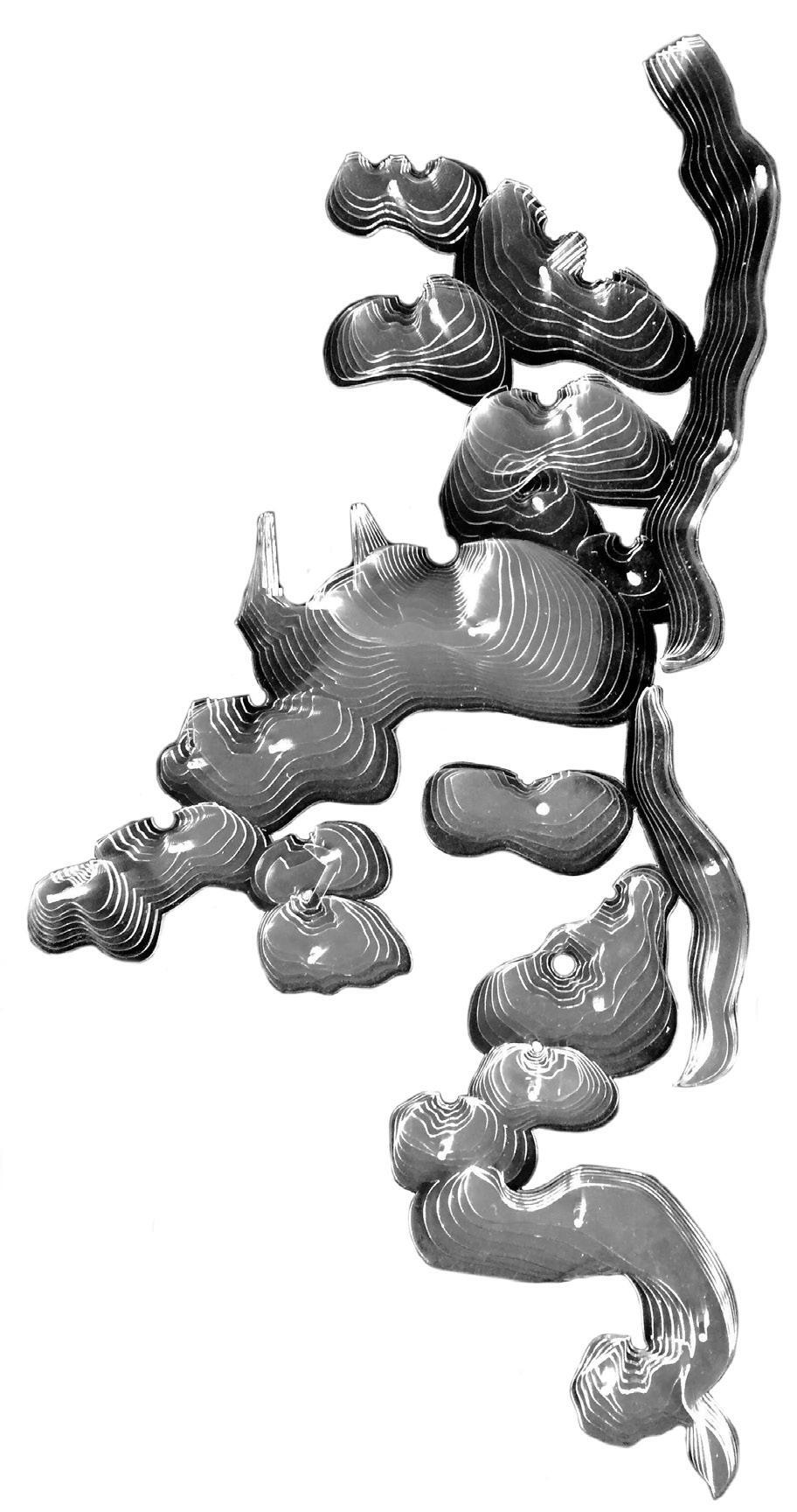
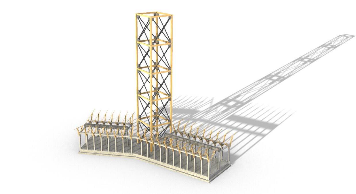
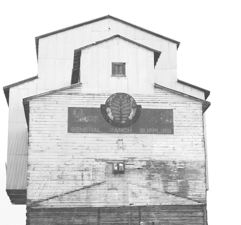
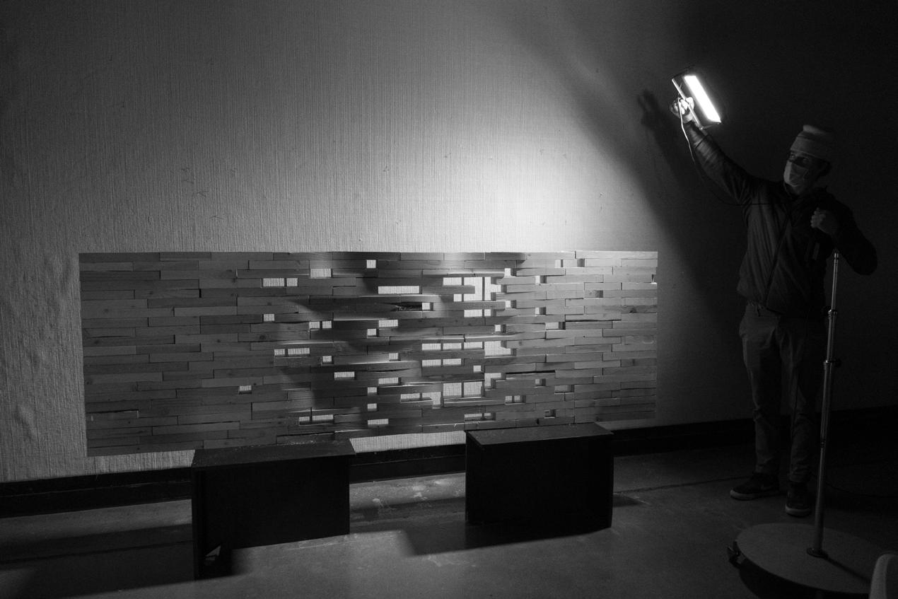
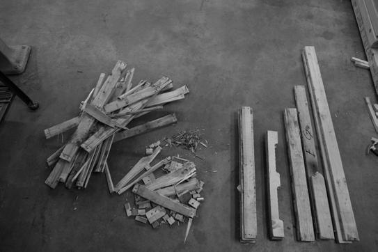
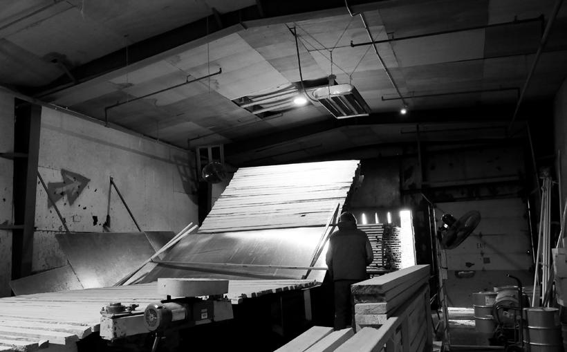
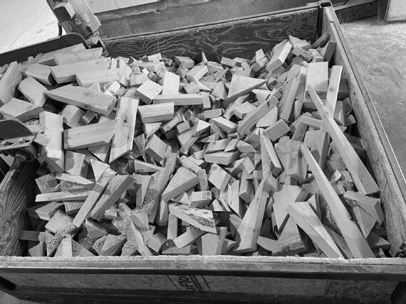
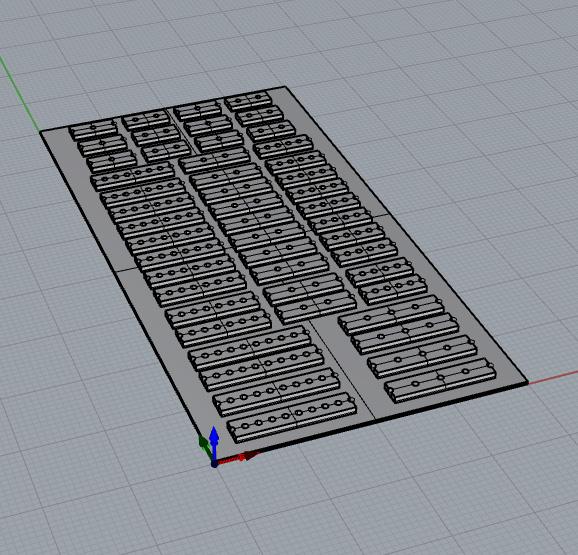
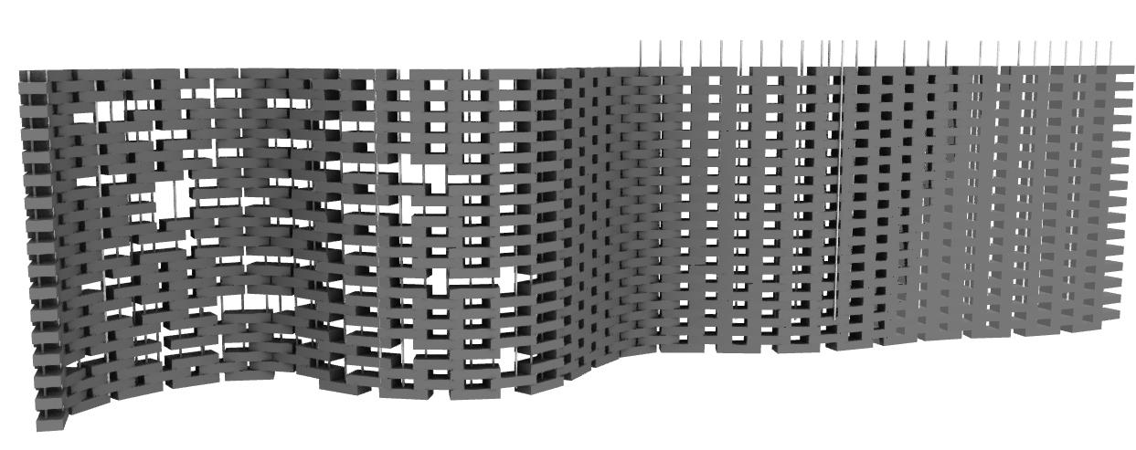
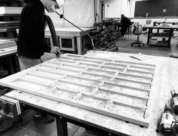
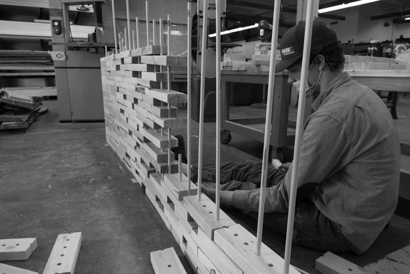
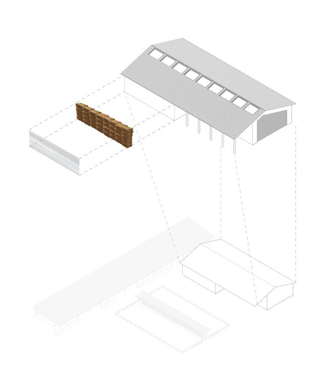
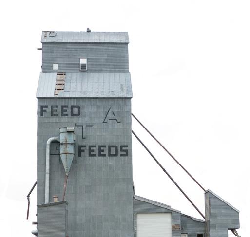
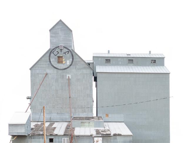
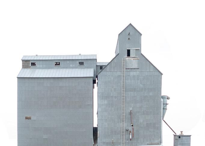
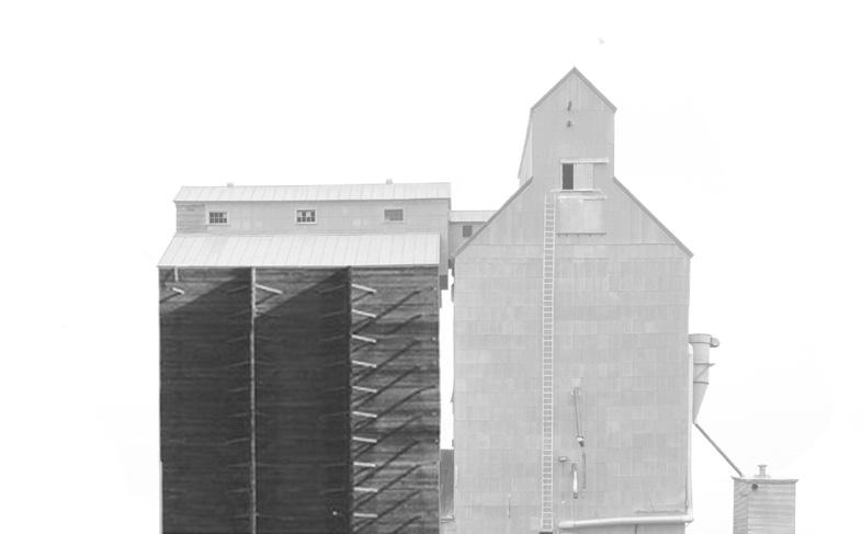
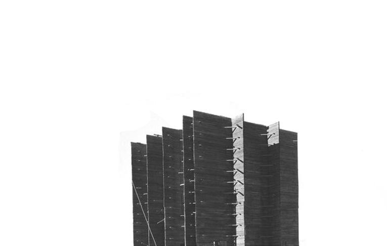
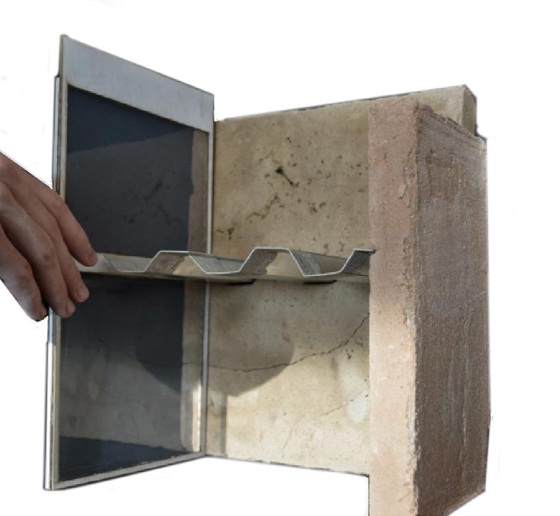
During a ‘locally fabricated’ studio conducted by MASS Principal Architect and Montana native Sarah Mohland, vernacular construction, and sourcing were researched to combat what we dubbed ‘fast architecture.’ After this stage, we attempted our scaled-down physical manifestation of lo-fab and its potential. To do this, I focused on the historic vernacular architecture of grain elevators in rural Montana, constructed using a method called ‘cribbing,’ which is the stacking of 2x4s. To attempt to re-invent this inherently beautiful method more sustainability, I sourced waste wood 2x4 scrap from a local truss factory, stacked them in a gradient pattern, and dowel laminated the resulting wall to connect them without carbon-intensive metal fasteners, making it easy to reconstruct. Finally, to add interest and bring it into the 21st century, CNC technology to intensified the gradient and bring depth. The result was an easyto-understand, carbon-negative low-fab partition wall/rain screen.
02
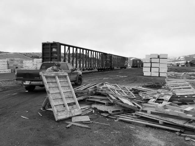
Trial + Error 01
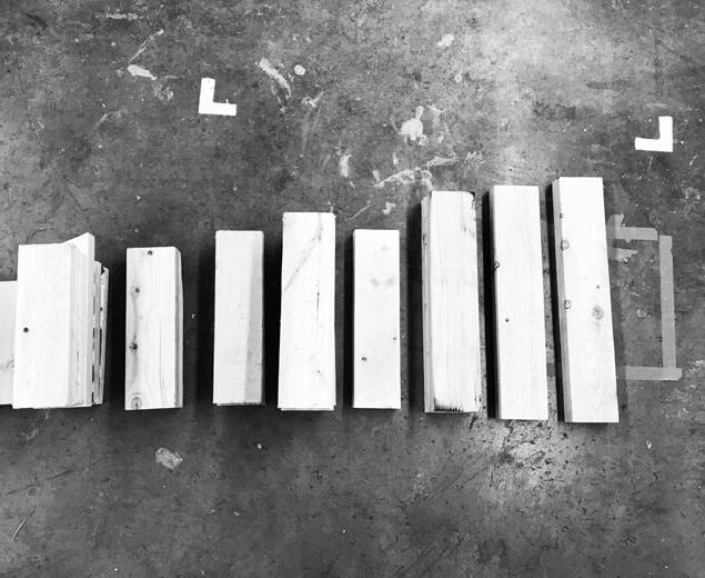
Pallets are collected and disassembled to use as a material source. Due to the time needed to remove the nails, the locally sourced waste material is deemed unusable.
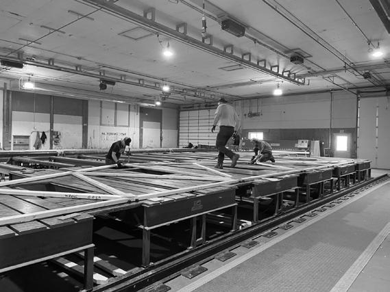
Local Source 02
A consistent source of waste 2x4 material was identified at local truss manufacturing plant, Kenyon Noble.
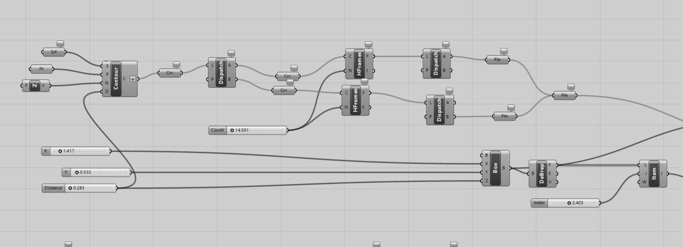
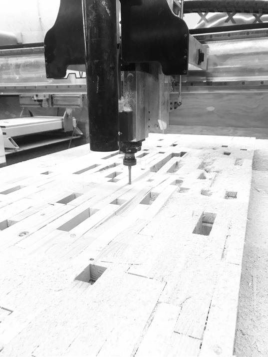
Once dimensions of our material was decided, parametric design was used to play with possibilities at a faster pace. Eventually, this led to exploration of CNC milling technology.
Grasshopper 03

CNC Milling
A template was created that allowed for a factory-like production of standardized pieces of 2x4. In addition, precise holes were drilled to allow for dowel lamination.
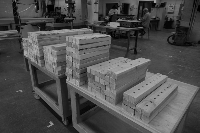
Kit of Parts 05
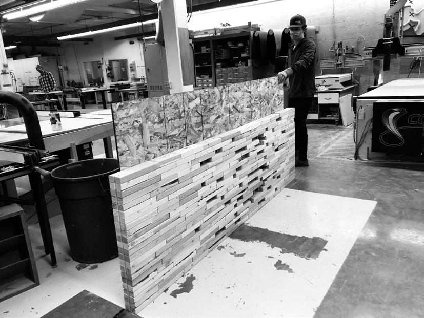
Combined with wooden dowels, the stud cutoffs formed a ‘kit of parts’ that could be easily assembled without glue or fasteners to a degree of customization.
06
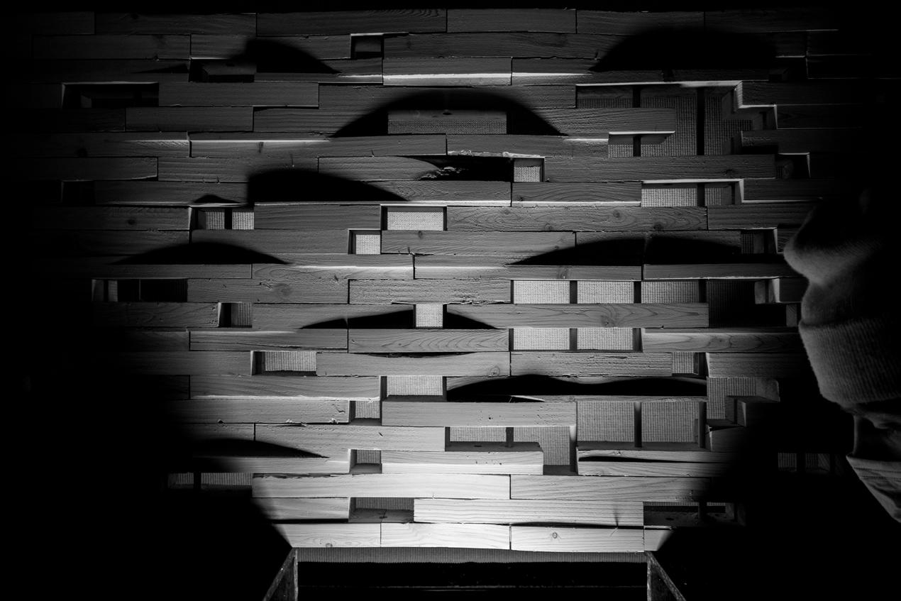
Final Touches
Once put together, the wall assembly was then drilled into plywood and placed back into the CNC to add aesthetic interest by playing with light and curves.
04
04

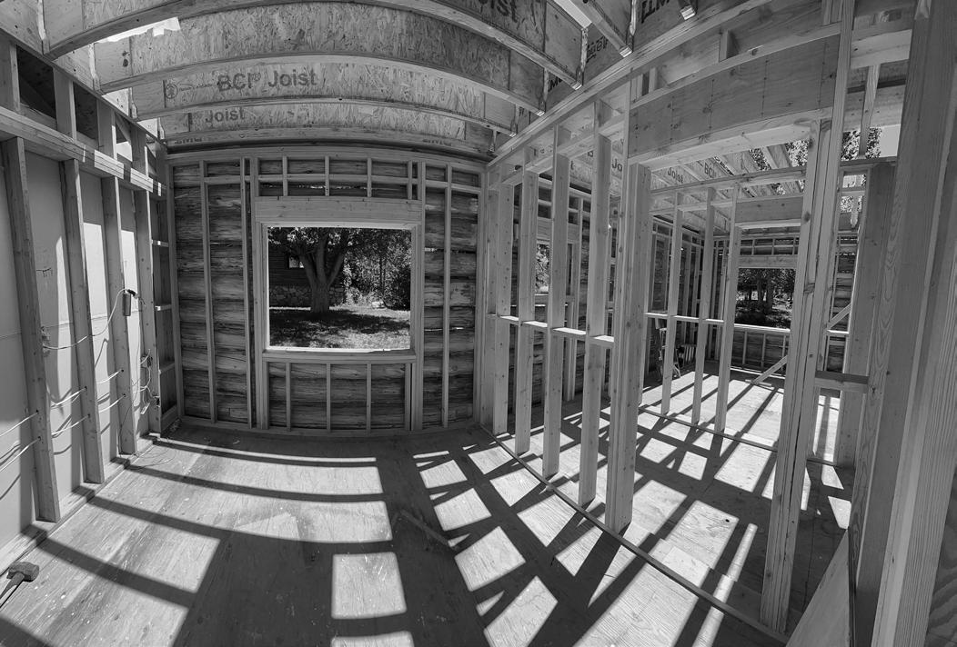
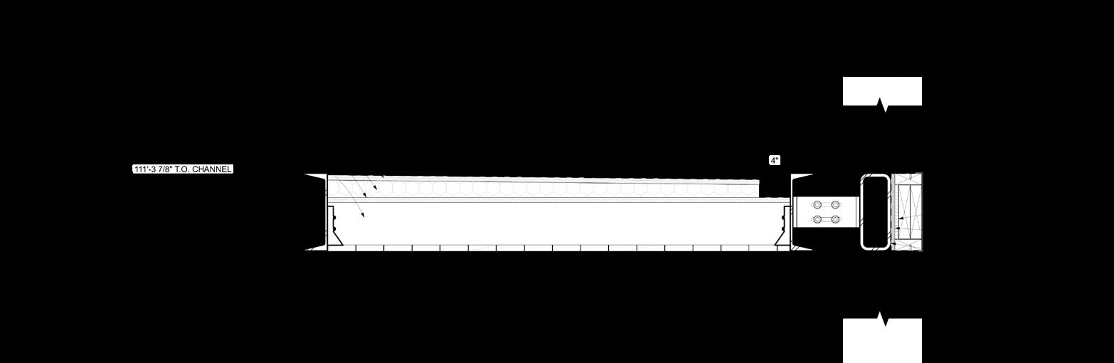
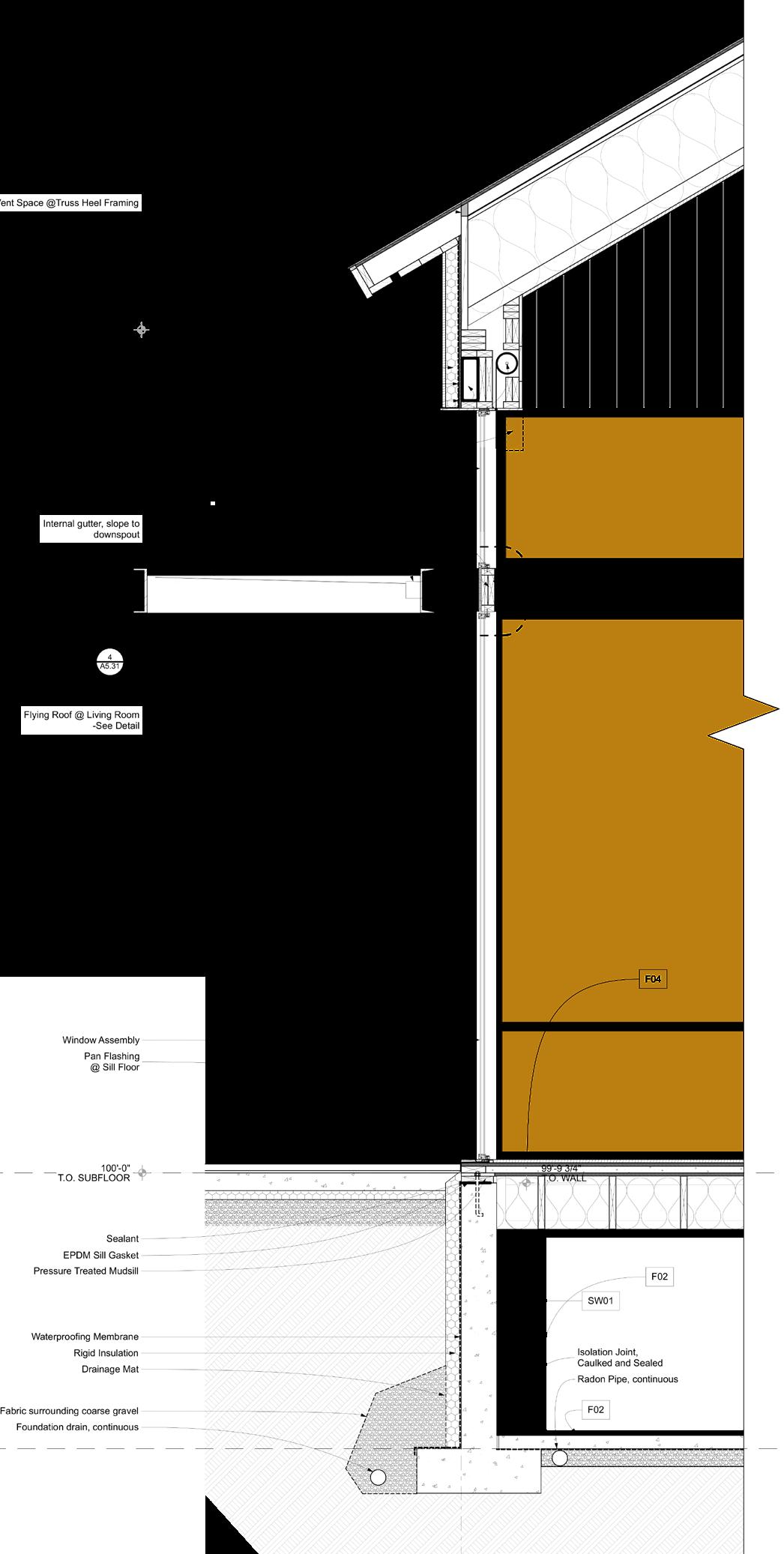
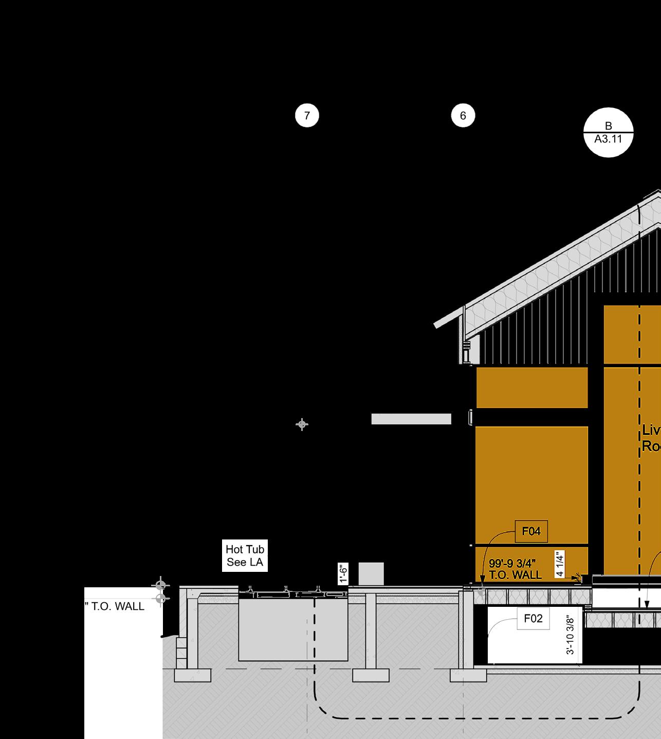
Vera Iconica Professional Experience
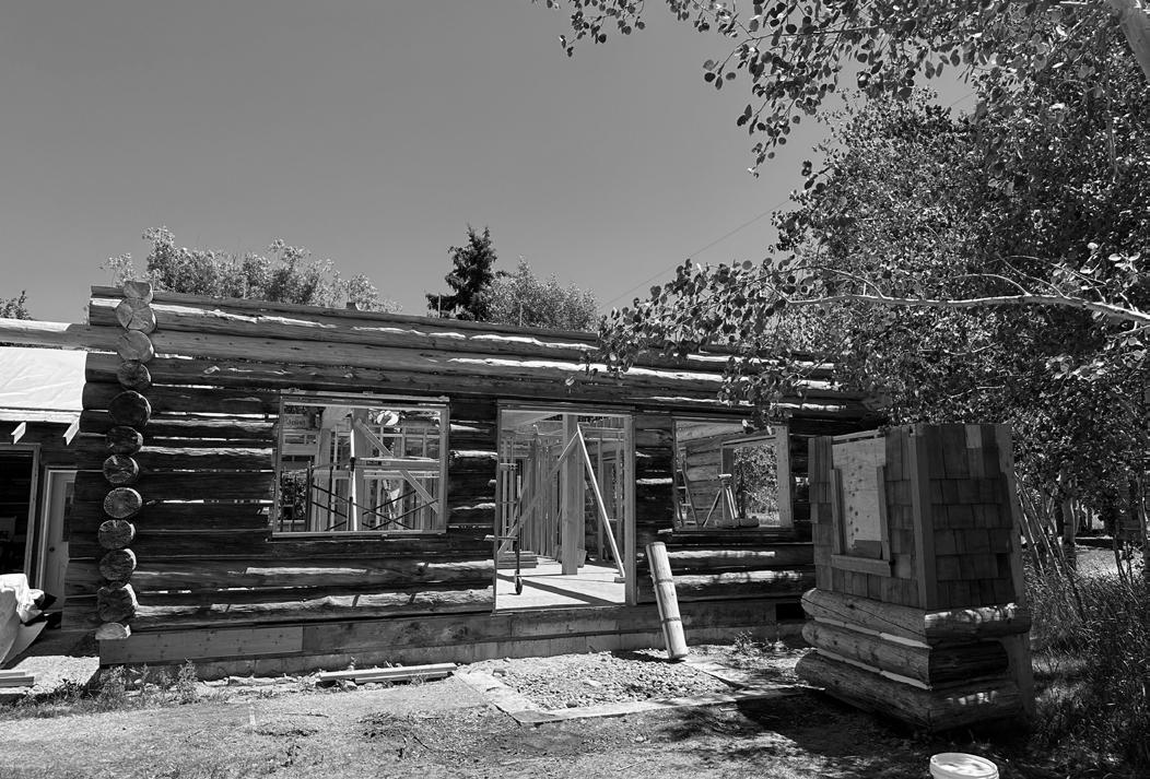
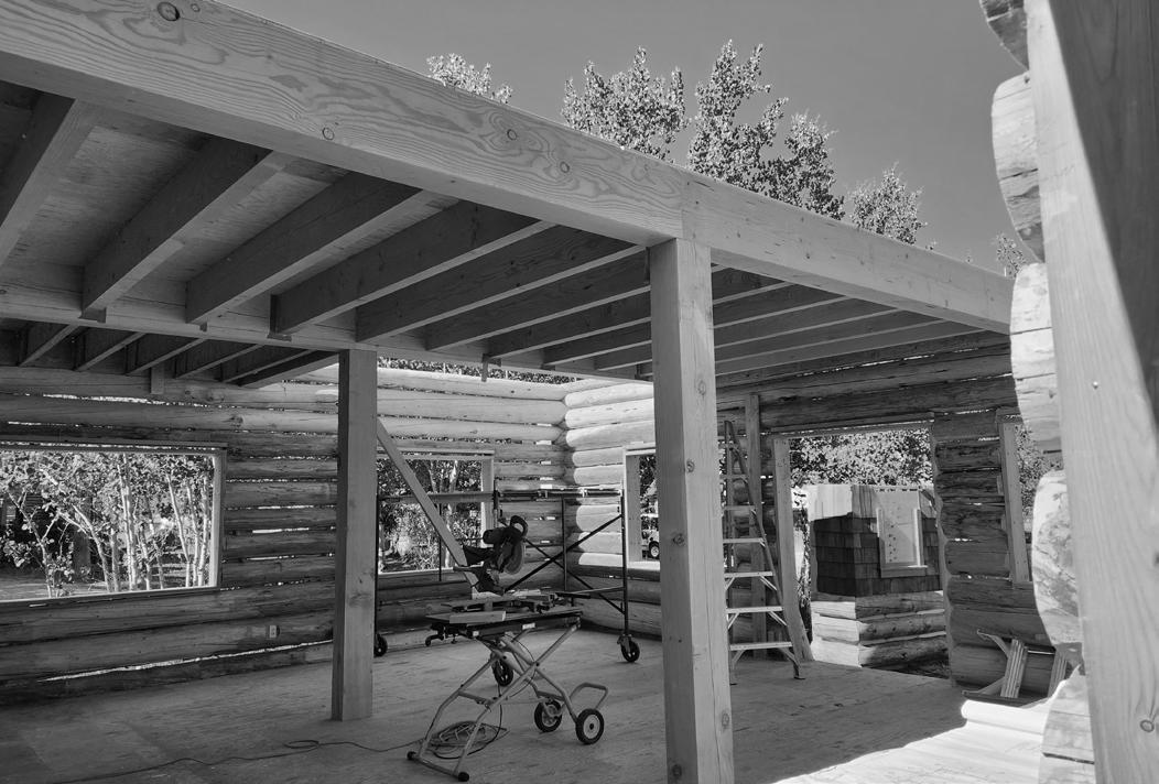
While at Vera Iconica Architecture, I worked on several residential projects of varying scales, budgets, and types. The following spreads show two opposing ends of that spectrum, with images highlighting a grasp of construction documentation and administration.
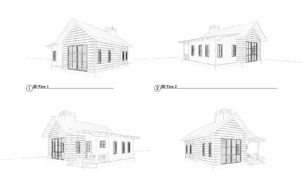
Project A exemplifies careful navigation of a second story addition to an existing log cabin. This project brought forth countless challenges in terms of structural engineering and the implementation of new building technologies to vernacular ones. Perhaps my proudest design input on this project was realized during the CA phase, when it was decided any removed logs be utilized as stair treads leading to the added second story.
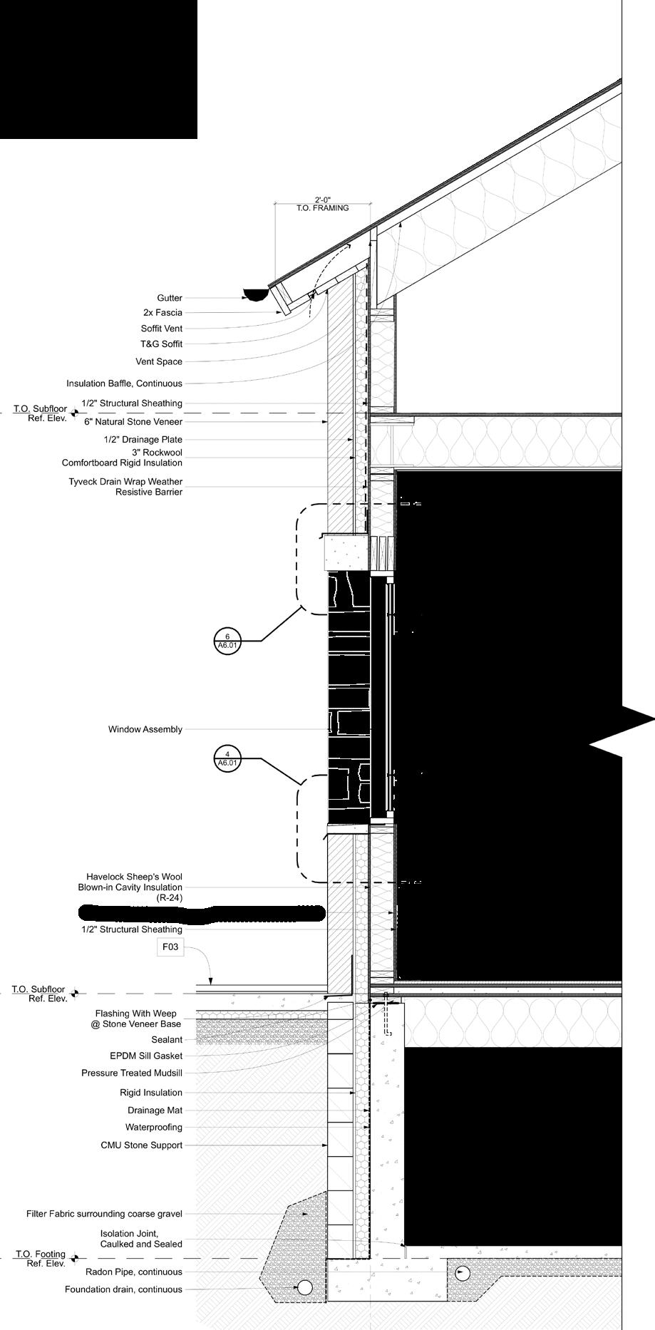
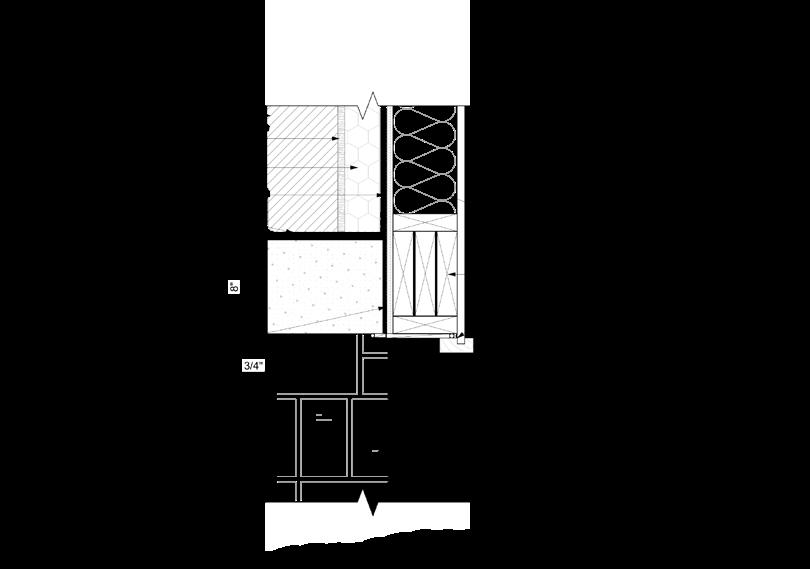
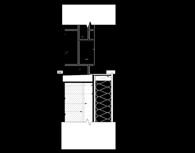
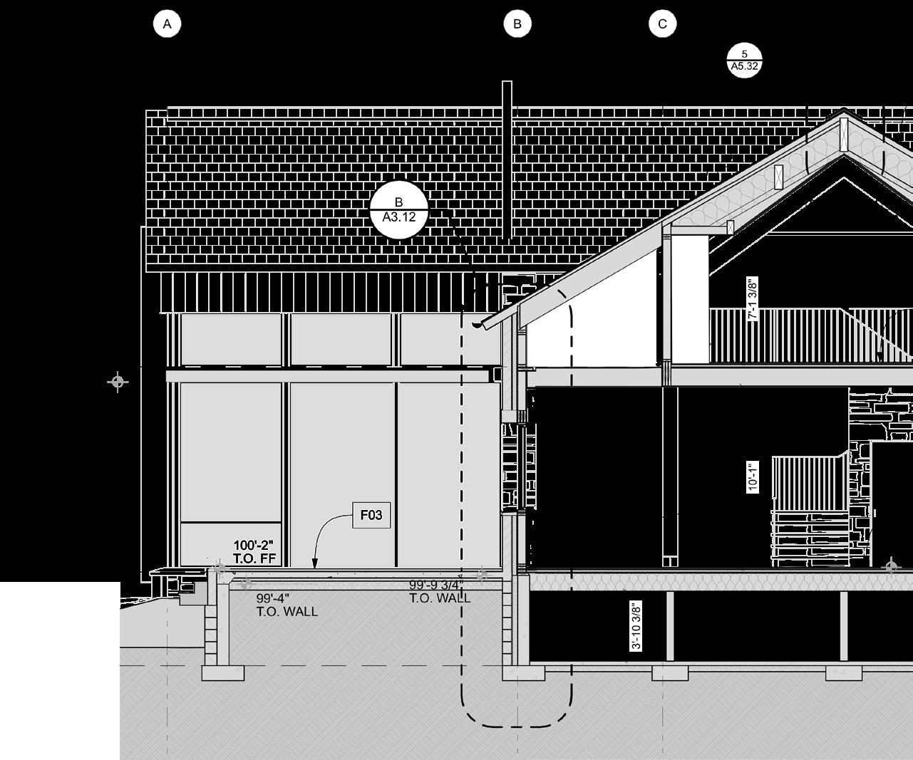
Project B, while being a single family residence, required the expertise of a commercial project. With 23 sections total, much of the detailing was centered around the steel space-frames supporting the double height center hall space which were coupled by extruded steel awnings suspended over walkways. While conducting a structural model of the project, I was able to work with civil engineers to detailing concealed gutters within the awnings in order to provide freedom for landscape design opportunities.
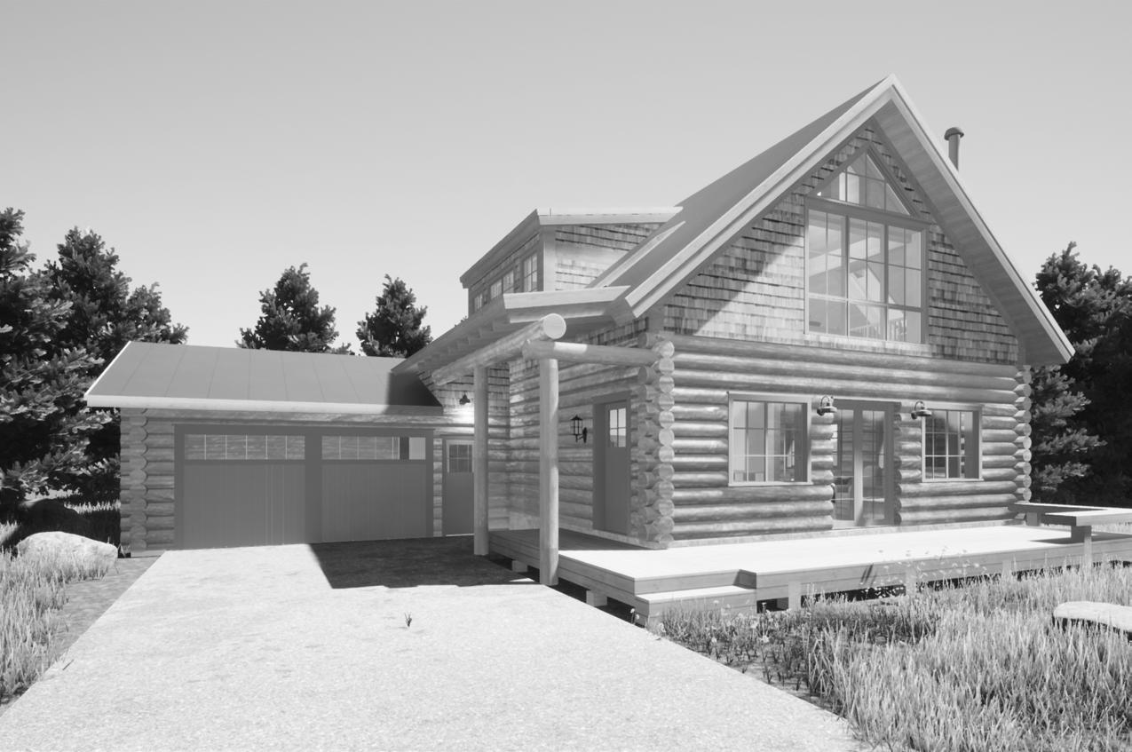
Project A
Type: Log Renovation, Residential
Size: ~1,700 Sq. Feet
Location: Jackson, Wyoming
Team Size: 4
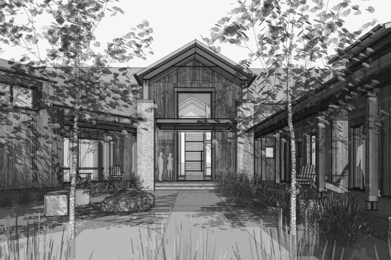
Project B
Type: New Construction, Residential Size: ~11,000 Sq. Feet
Location: Jackson, Wyoming
Team Size: 7
06
Project A
EXTER OR MATER AL KEY NOTESE T R OR O N H & NEW C NK NG S NG 3 CED R S AK S F SH 1 HR R R T RDA T RE T D T N CO OR 2 - T D F SC C DAR F N H T N OLOR 3 - BDGU TE S AL - ROUN GU TE S DOWNS OUT N SH COPP RDE K X LA KA Y L OW CE AR ECK NG F SH UN N SHE & W NDOWS AND OORS A UM N M C AD WOOD N H NT R ORDO GL S R EX ER OR - C AD S RRA P C C AT N GR EN 5 WA N COT E S NG S ONE F N S E S NG TO REMA NE T R OR - C AD CO OR TO M TC ROO NG CO UMN LOG POS RE S RUC URA F SH MA CH EX T NG OG N H1 1 1 1 1 1 2 91S O-3 4 B O E M2R C R E GH0- LE R1 - F T O W DOW W--P E-11 - 5 81 6 - V F T O W N OW 7 -3 O GH F X UREO W NDOWS57 1S OA 4D H - 4 SOUTH ELEVATION - 3 WEST ELEVAT ON 0 8 - 5 GARAGE ELEVATION ROOFING STA ND NG SEAM BONDERIZED METAL EXTER OR MATERIAL PALETTE S D NG CEDAR SHAKE W TH L FET ME STA N S D NG EX ST NG LOG W TH NEW WH TE CH NK NG W TH COPPER L GHT F XTURE WA NSCOT EX ST NG TUMBLED STONE W NDOWS PAT NA GREEN TR M SHEET TITLE DES PROJECT NO DRAWN BY COPYR GHT MARK DATE A2 DOCUMENTAT O V WL CT DD D g 2020-01 P 1 6 2 P C ns MOW b 2M 9770 N Bu EXTER OR ELEVA WE KELLY WELL RENOV Kr st Onz 9770 N B d Ke WY 30 262-22k k@g Ve a con 680 S C h PO Box 793 Ja kso WY 307-2 1-1 h @ 9 3 2 1 4 1-O E M-3 O-3 H G a8 - 3 4 V DOO-W --1 CR W P E GR E---R- 2 NORTH ELEVATION - 1 EAST ELEVAT ON W R SHEET T TLE DESCR PT ON PROJECT NO DRAWN BY CHK D BY COPYR GHT MARK DATE A2 01 DOCUMENTAT ON SETS V A h WL CT CH SS g p 2020-014 P S 1 1 0 2 P g Add d # Con uc o Do umen 9 70 N B dge Lan Ke y WY 3011 EXTER OR ELEVAT ONS - NORTH & EAST KELLY CABIN WELLNESS RENOVATION K i O k & B t Y g 97 0 N B g L Ke y WY 8 011 2 2-225-985 o @ a o V I A h 80 S C h S # 01 PO B x 479 ac son WY 830 1 307-201-16 2 @ d EXTER OR MATER AL KEY NOTES D G E S NG LOG N SH STA N CO OR - CL AN D W O MO EX ER OR O F N SH & N W CH K NG D G C DAR SHA ES N H H F RE RE ARD NT T EA ED S A NOOF STAND NG S AM M T L F N S BO DER ZEOF T ONGU & GROOV CE AR F SH S A N CO OR - T DMB R RA T RS DOUG AS F R E TR CT N H T N COL R - BD W N OW AN DOOR L M NUM LA WOOD F N SH N ER OR-LA H N B EA ME A N SH TO M T H ROO NGEX ER OR - CL D COLO TO MA CH OOF NG COL M OG P ST R TR CTU A N H M T H E S NG LOG1 4 6 9 3 5 6 3 2 1-0 O O- 2 B A- 0 T U U E H Gg G0 - F T O DOOR9 1 1-B--9 T O A-6R e F h G5 g W - 2 NORTH ELEVAT ON - 1 EAST ELEVATION ROOF NG STA ND NG SEAM BONDER ZED METAL EXTER OR MATER AL PALETTE S DING CEDAR SHAKE W TH L FET ME STA N S DING EX ST NG LOG W TH NEW WHITE CH NK NG W TH COPPER L GHT FIXTURE WA NSCOT EX ST NG TUMBLED STONE WINDOWS PATINA GREEN TR M SHEET T TLE DES PROJECT NO DRAWN BY COPYR GHT MARK DATE A2 DOCUMENTAT O V WL CT DD D g 2020-01 P 1 2 P C s M oOW b 2M 9770 N Bu EXTERIOR ELEVA EA KELLY WELL RENOV Kr st Onz 9770 N B d Ke WY 830 262-22 -9 k k@g Ve a con 680 S Cac e PO Box 793 Ja s 307- 01-1 h @ d 1 2 3 3 1 4----H G d11T O W DOWSM A B C D--O AMS GH G d0-DA 0A 5 A &D S AL 1 - 4 SOUTH ELEVATION S AL 1 - 3 WEST ELEVATION SC L -0 5 GARAGE ELEVATION SHEET T TLE DESCR PT ON PROJECT NO DRAWN BY CHK D BY COPYR GHT MARK DATE A2 02 DOCUMENTAT ON SETS V a c n a A h e u WL CT CH SS DD 8 Des g De e opmen 2020-014 Pe m Se P g Add #2 2 2 2 C D 977 N B dg L Ke y WY 83 11 EXTERIOR ELEVATIONS - SOUTH & WEST KELLY CABIN WELLNESS RENOVATION C EN Kr st Onz k & Bar on Young 9770 N B dg L K WY 830 1 -kko z k@gm c m AR H EC Ve a con ca A ch ec ure nc 680 S C h S #101 PO B 4793 J k WY 83001 -che sea@ve a con ca c m

08
Project B
10
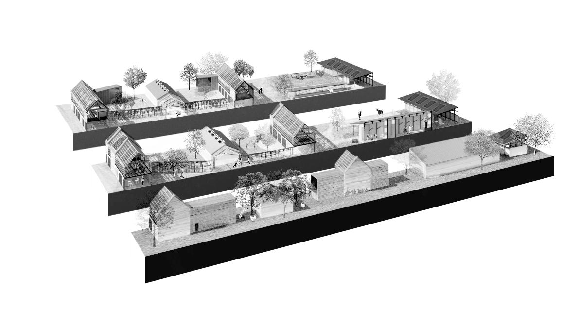
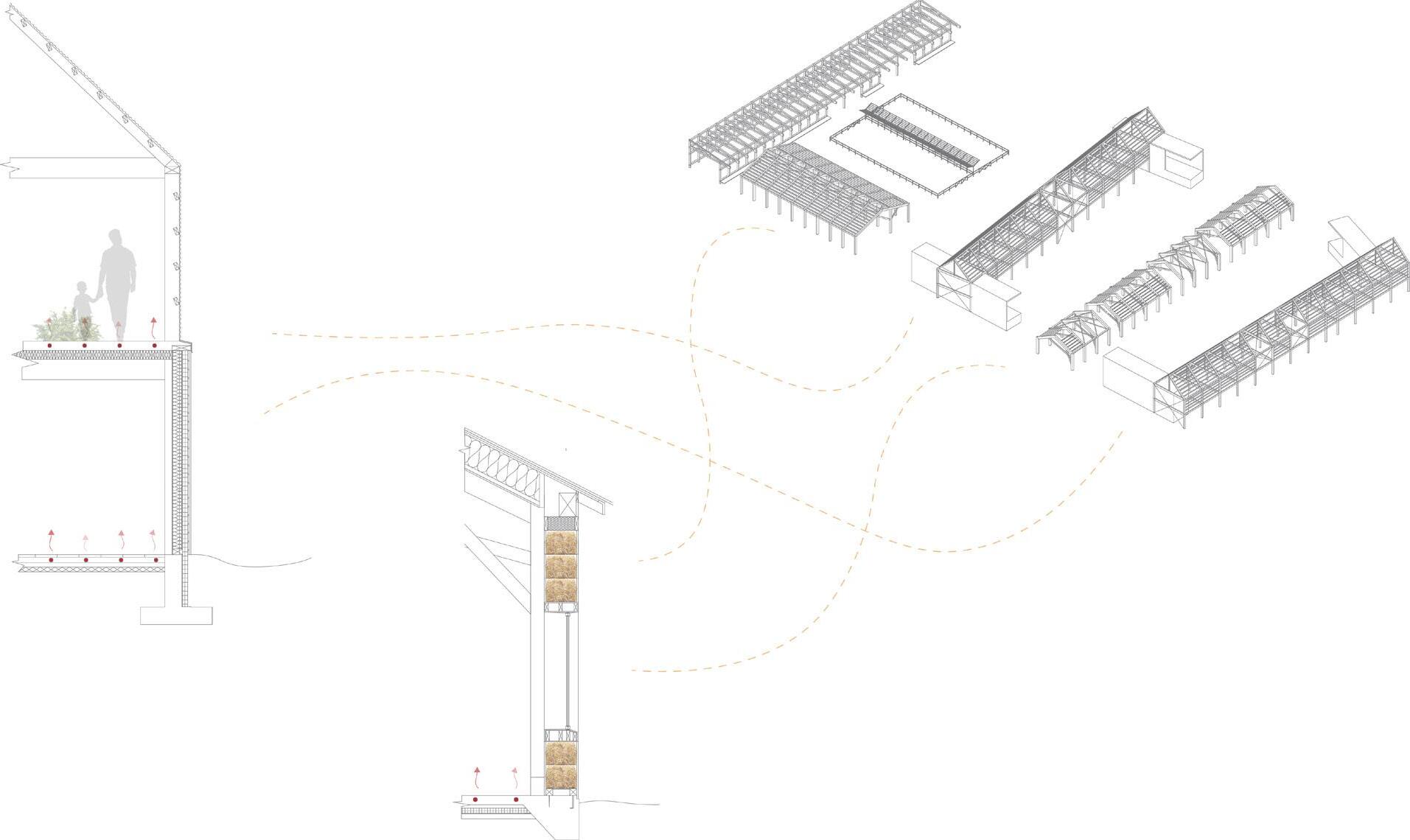
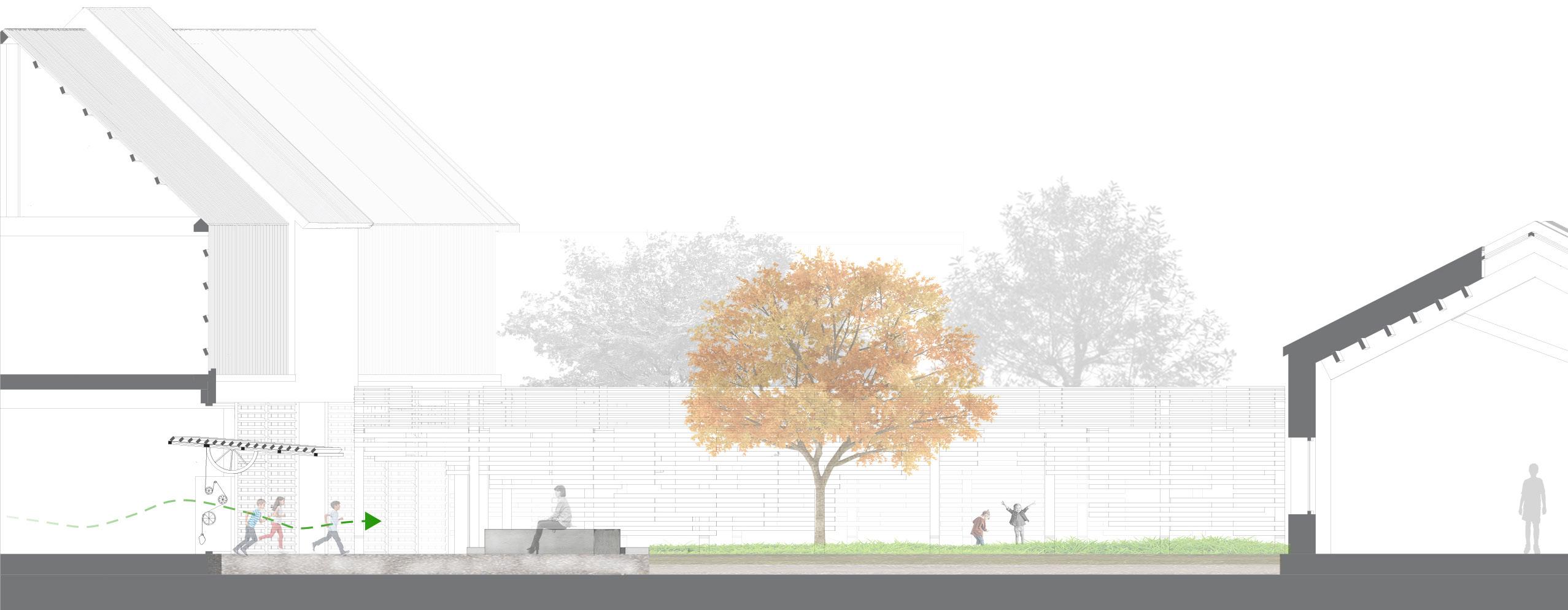
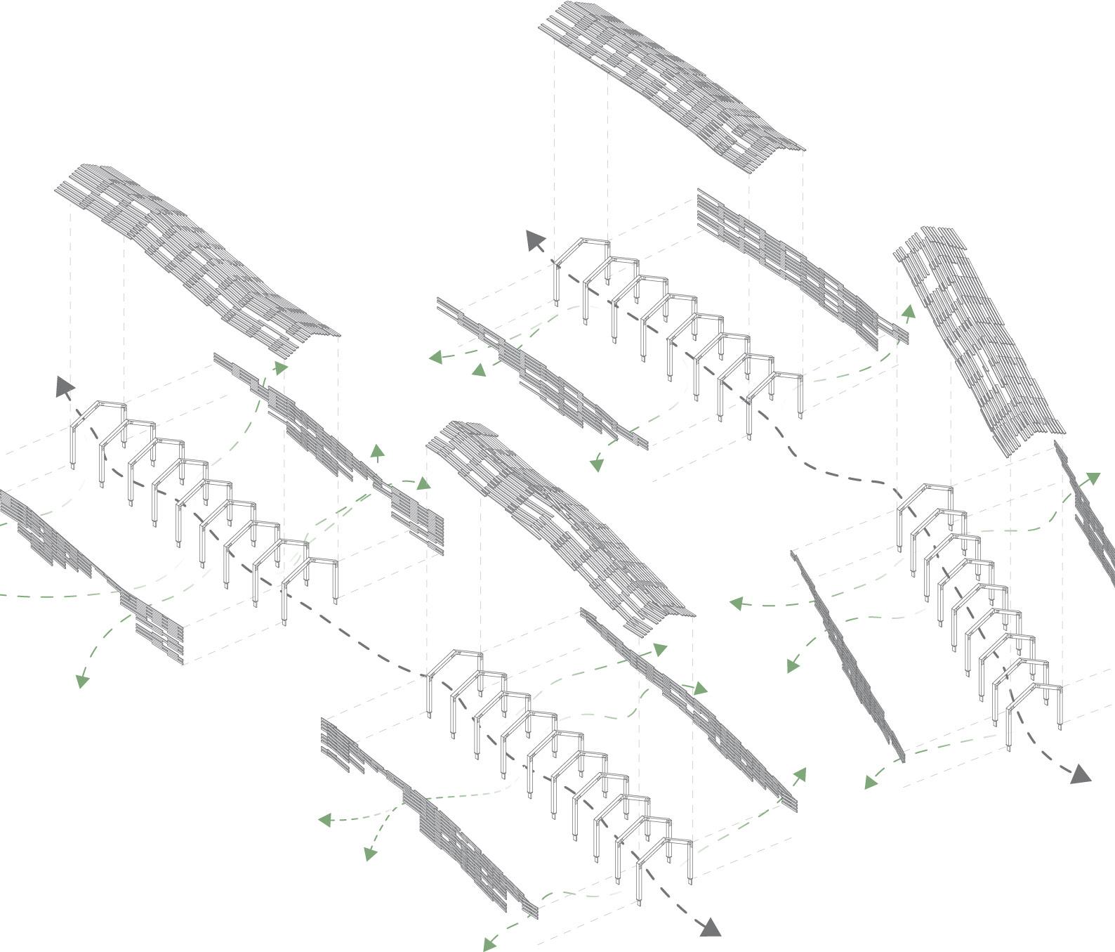
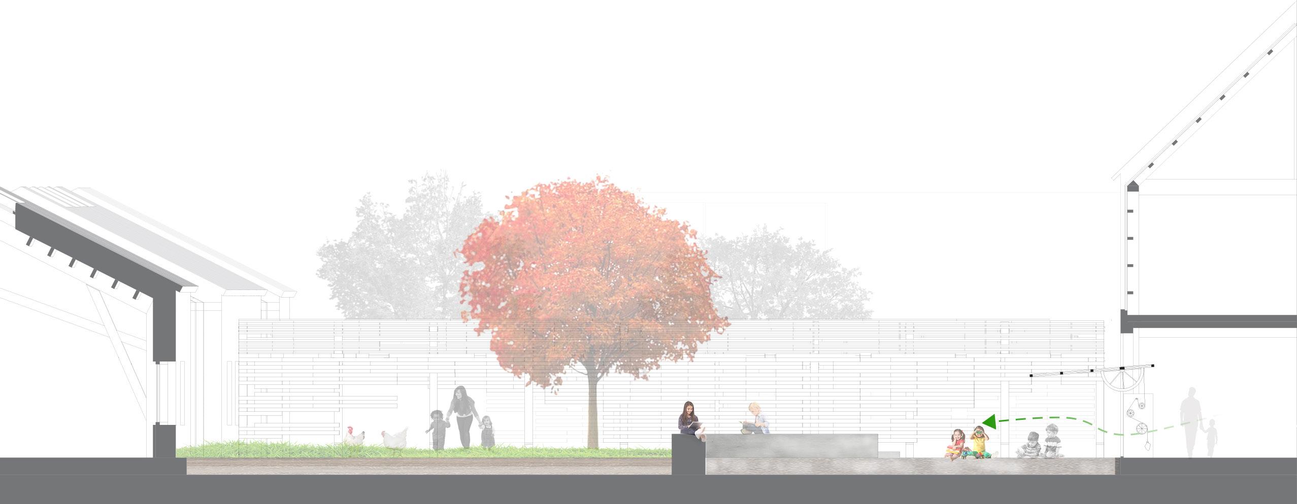
Montessori Digital Workflow
Within the Montessori education system exists an instilled importance of respect for the environment, self-reliance, and observation. These values are paralleled by the ecology of the Western homestead. By studying and manifesting traditional typologies, we can better learn to synchronize an educational facility with its surroundings in a way that is conducive to the installment of these values. When done successfully, a more sustainable built environment will be created. This project, completed during a Master’s studio, aims to embody these ideals.
12
14
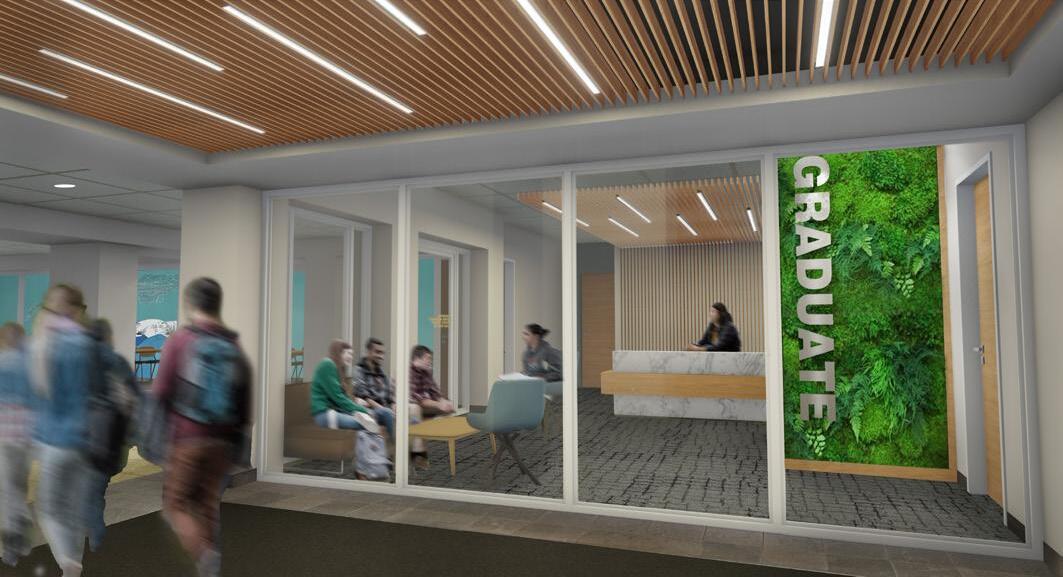
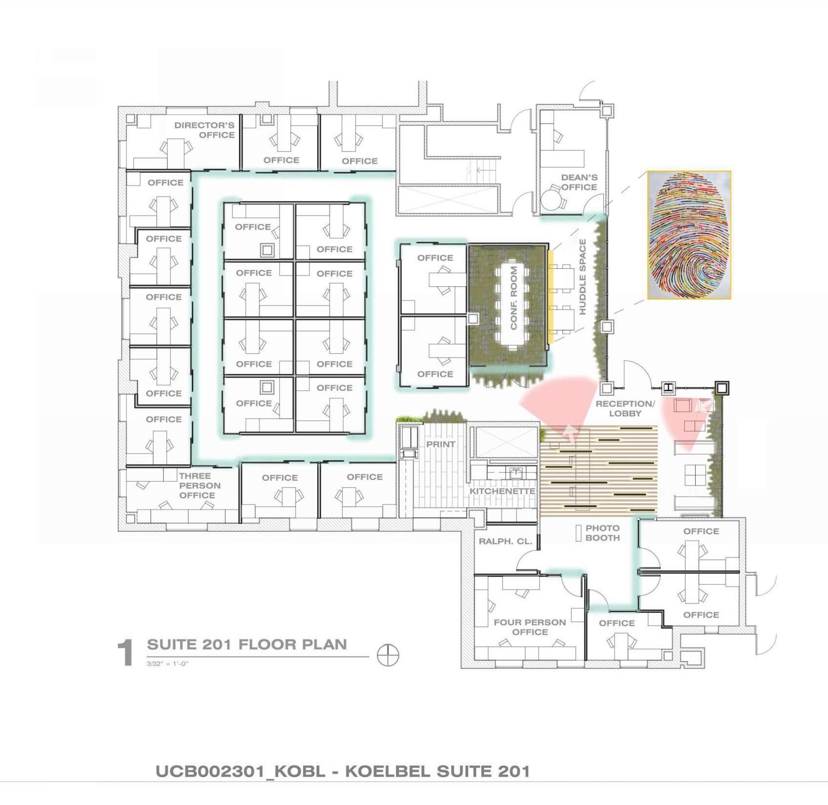
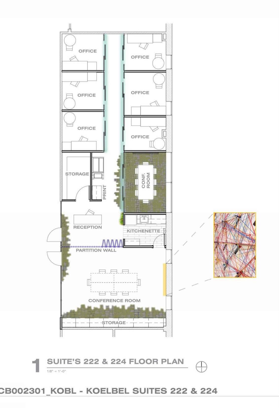
Koelbel Renovations
Architectural Workshop
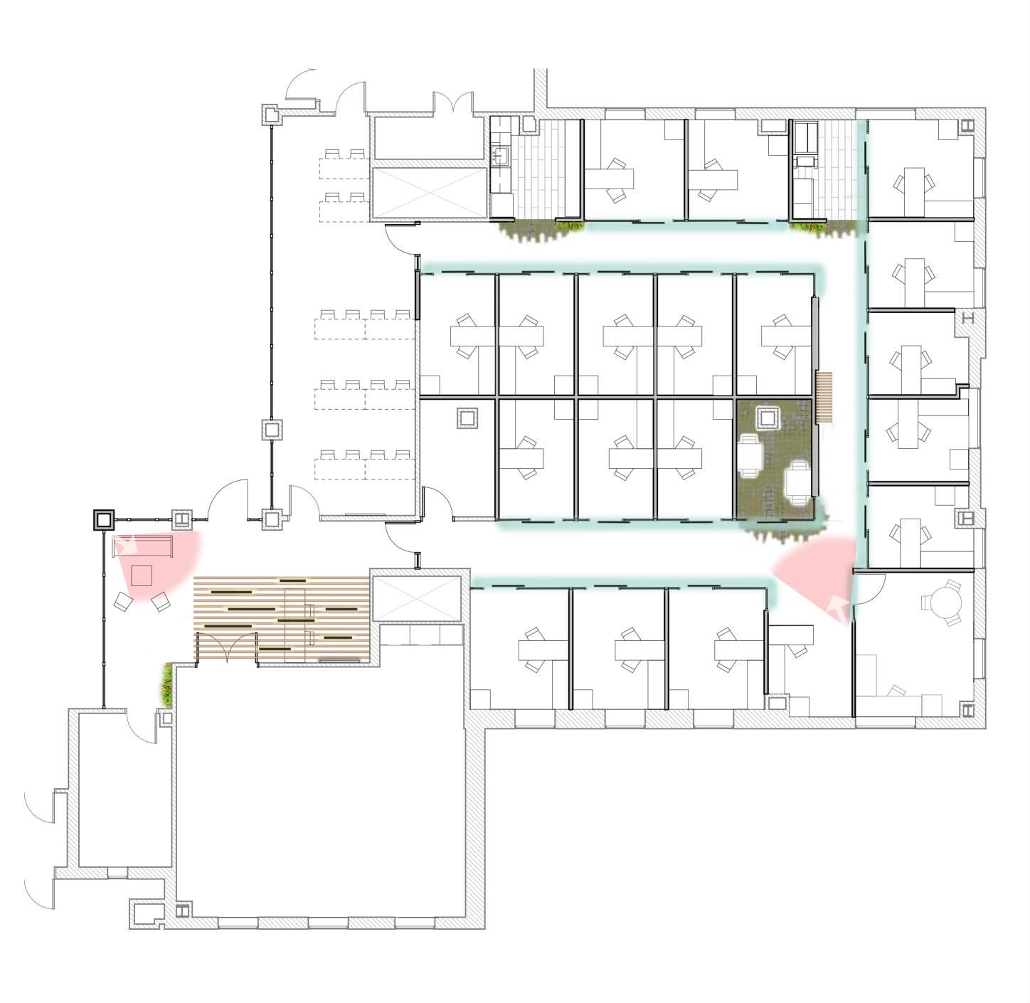
In my time at Architectural Workshop I’ve had the pleasure of expanding my experience into higher education with a plethora of the firm’s working being with the University of Colorado. These projects come mainly in the form of renovations which require careful navigation of both local building codes and University building standards. The main project I’ve been tasked with is the renovation of both the Graduate and Undergraduate office spaces in Koelbel Hall. Currently nearing construction, I’ve had the opportunity to be involved in a variety of tasks ranging from on-site surveying and schematic design to 100% CD’s.
The following images showcase a code plan conducted for the building, as well as of schematic design plans created for a client presentation and their transition into construction documentation.


CONTACTS: UNIVERSITY OF COLORADO AT BOULDER RESEARCH LABORATORY NO.2 1540 30TH STREET, 3RD FLOOR, BOULDER, COLORADO 80309 PROJECT MANAGER: JENNIFER O'NEILL PH: 303-591-6460 BUILDING OWNER: ARCHITECT: MECHANICAL: KALAMATH ST. DENVER, CO 80223 PH: 303-788-1717 CONTACT: MARK BOWERS (PIC) KEVIN BECK (PM) INTERIOR DESIGNER: BE.STUDIO 3000 LAWRENCE STREET -SUITE 138 DENVER, CO 80205 PH: 303-947-7473 CONTACT: CHRISTY KREHBIEL ELECTRICAL: SHAFFER BAUCOM 3900 S. WADSWORTH BLVD. SUITE 600 LAKEWOOD, CO 80235 PH: 303-986-8200 CONTACT: GARY SHAFFER (PIC) CHRISTOPHER CIPRIANI (PM) SHAFFER BAUCOM LAKEWOOD, CO 80235 PH: 303-986-8200 CONTACT: JAY H McCABE SHAFFER BAUCOM 3900 S. WADSWORTH BLVD. SUITE 600 LAKEWOOD, CO 80235 PH: 303-986-8200 CONTACT: CHRISTOPHER CIPRIANI (PM) PLUMBING: ACOUSTICAL ENGINEER: 5420 WARD ROAD ARVADA, CO 80002 PH: 719-602-9059 CONTACT: ANDY BURKART, CTS-D LOCATION: PROJECT LOCATION PROJECT NO.: DRAWN BY: CHECKED BY: PNOTFORCONSTRUCTION RELIMINARY ARCHITECTURAL WORKSHOP DENVER, COLORADO PROJECT NUMBER: UCB001025 2310KS JAN 2024 WL KB KOELBEL REMODELSUITES 200, 201, 222 & 224 UNIVERSITY OF COLORADO BOULDER G-001 COVER SHEET, PROJECT INFORMATION 75% CONSTRUCTION DOCUMENTS 03-29-2024 UCB001025_KOBL -KOELBEL SUITES 200, 201, 222 & 224 COLORADO BOULDER DATEDESCRIPTION 02-16-24SCHEMATIC DESIGN REVIEW 03-29-2475% CONSTRUCTION DOCUMENTS
ARCHITECTURAL WORKSHOP, LLC. ALL RIGHTS RESERVED ©


LEGEND: EXIT EGRESS NO WORK THIS AREA 1 HR FIRE RATED 2 HR FIRE RATED AREA OF WORK SMOKE EXHAUST BOUNDARY 756 SF OCC: A-3 CLASSROOM 49 189 SF OCC: B* ACC. TO B 13 391 SF OCC: B* ACC. TO B 27 117 SF OCC: B* ACC. TO B 8 862 SF OCC: B BUSINESS 6 4060 SF OCC: B BUSINESS 28 152 SF OCC: S STORAGE 1 4642 SF OCC: B BUSINESS 31 34 OCC 5 1 REQD 36 PROV 34 OCC 5.1" REQD 48" PROV. 23 OCC 3 45 REQD 4 PROV 22 OCC 3 3 REQD 36 PROV 15 OCC 2.25" REQD 36" PROV. 2 OCC 4 0 REQD 3 PROV 59 SF OCC: S STORAGE 1 89 SF OCC: S STORAGE 1 AREA OF WORK CODE STUDY KEY A-3 B B* S AREA OF WORK ORIGINAL BUSINESS SCHOOL TYPE 3A CONSTRUCTION WOOD FRAMED INTERIOR PARTITIONS 2008 BUILDING ADDITION CONSTRUCTED AS TYPE 2A, BUT NO FIREWALL PROVIDED BETWEEN EXISTING AND NEW CORR CR220 OCC 62 55 REQD O 4 6 OCC 6 9 REQD 2 PROV 458 OCC 68.7" REQD 72" PROV. OCC. OCC. OCC. OCC. OCC. OCC. OCC. OCC. OCC. 197 OCC 3 4 REQD 57 PROV 115-3 "OVERALLDIAGONALDISTANCEREQDEXTSEPERATION 115-3 X13=38-5 39-6EXITSEPERATIONPROVIDED 10311 OVERALLDIAGONALDISTANCEREQDEXTSEPERATION 10311 X1/3 = 347 45-10 EXITSEPERATIONPROVIDED OCC: B BUSINESS 794 SF 8 OCC. OCC: B BUSINESS 442 SF 30 OCC. OCC: B BUSINESS 702 SF 36 OCC. OCC: B BUSINESS 705 SF 36 OCC. OCC: B BUSINESS 288 SF 20 OCC. OCC: S STORAGE 108 SF 1 OCC. OCC: B BUSINESS 197 SF 14 OCC. OCC: A-3 ASSEMBLY 982 SF 50 OCC. OCC: A-3 ASSEMBLY 982 SF 50 OCC. OCC: A-3 ASSEMBLY 1343 SF 68 OCC. OCC: B BUSINESS 424 SF 22 OCC. OCC: B BUSINESS 253 SF 17 OCC. OCC: B BUSINESS 715 SF 48 OCC. OCC: B BUSINESS 254 SF 17 OCC. OCC: S STORAGE 114 SF 1 OCC. OCC: S STORAGE 114 SF 1 OCC. OCC: B BUSINESS 2195 SF 22 OCC. OCC: B BUSINESS 7782 SF 78 OCC. OCC: B BUSINESS 397 SF 20 OCC. OCC: B BUSINESS 475 SF 24 OCC. OCC: S SERVICE 211 SF 1 OCC. OCC: B BUSINESS 1253 SF 13 OCC. OCC: B BUSINESS 374 SF 25 OCC. OCC: A-3 ASSEMBLY 1175 SF 79 OCC. OCC: B BUSINESS 365 SF 25 OCC. OCC: A-3 ASSEMBLY 3894 SF 260 OCC. NON COLOR CODED OCCUPANCIES ARE TAKEN FROM PREVIOUS RECORD DOCUMENTS PROVIDED BY UNIVERSITY. CORRIDOR LENGTH = 36' < 50' 242 OCC 3 63 REQD 36 PROV STA R EGRESS 220 OCC 44 REQD 4 PROV 66 SF OCC: S STORAGE 1 OCC. *** CONTRACTOR TO PROVIDE MAXIMUM OCCUPANT LOAD SIGN FOR CLASSROOM TO LIMIT OCCUPANCY BASED ON EGRESS LIMITATIONS. CU PM TO PROVIDE APPROPRIATE INFORMATION TO CENTRAL SCHEDULING FOR CLASSROOM SIZES BASED ON EGRESS LIMITATIONS. *** OCC. PROJECT NO.: DRAWN BY: PNOTFRELIMINA ARCHITECTURAL WORKSHOP PROJECT NUMBER: UCB001025 BUILDING CODE: KOBL 2310KS WL KOELBEL SUITES 200, 224 UNIVERSITY OF COLORADO G-004 BUILDING CODE DATEDESCRIPTION 02-16-24SCHEMATIC 03-29-2475% 16


REF. M N O P Q R 3.3 3.4 3.5 3.8 4 4' 5 5.5 OFFICE 208W OFFICE 208T OFFICE 208R OFFICE 208P OFFICE 208N OFFICE 208M OFFICE 208L DEAN'S OFFICE 208K OFFICE 208F OFFICE 208D OFFICE 208B OFFICE 208G OFFICE 208E OFFICE 208C STORAGE 208A OFFICE 208Y OFFICE 208X OFFICE 208V OFFICE 208U OFFICE 208Z CLASSROOM 204 AV CLOSET 202 RECEPTION 200 STUDENT STUDY 206 MECH 210 208B 208D 208F 208L 208M 208N 208P 208R 208U 208V 208X 208Y 208Z 208G 208E 208C 208W 208T TEAM ROOM 208H EX 5.9 EX 14 9 TYP. 14 14 14 14 14 14 14 14 3 3 3 TYP. 9 TYP. 9 TYP. 9 TYP. 9 9 9 TYP. 9 6 EX 17 HMF 18 EX 208A 11 14 8 1 TYP. E 2 D B 2 C 2 5 PRINT 208S A TYP. 1 TYP. 1 TYP. ASSIST. OFFICE 208J KITCHEN 208AA CORR CR200 A-402 9 208H A.1 B.1 D.1 HMD 208K HME 206A 2 2 TYP. TYP. 3 13 13 13 13 13 14 TYP. A-401 A-401 A-401 4 A-504 A-502 6 10' 4 7/8" 10' 7/8" 7' 7" 10' 1/8" 9' 10 7/8" 10' 7/8" 9' 1/8" 8 1/4" 7 7/8" 8' 7/8" 14' 1/2" 1' 3" 9' 4" 9' 8 1/4" 8' 7 5/8" 12' 2" 12' 0" 4' 11 7/8" 12' 3/4" 10' 0" 3' 7 5/8" 1' 8" 7' 11 1/4" 7' 10 7/8" 7' 10 7/8" 7' 10 7/8" 7' 10 1/4" 3' 9 1/8" 2' 0" 2' 2 1/8" 7' 10 7/8" 7' 10 7/8" 7' 10 7/8" 2' 1/4" 2' 0" 3' 9" 12' 1/2" 5' 1/4" ALIGN ALIGN ALIGN ALIGN ALIGN ALIGN 1A 1A 1A 1A 1A 1A 1A 1A 1A 1A 1A 1A 1A 1A 1B 1B 1A 1A 1A 1A CORRIDOR CR208A CORRIDOR CR208 CORRIDOR CR208B 2 13 13 13 A-504 22 12' 7/8" 12' 1/8" 10' 6" 25 2 13 2 13 1 1 25 1C A-402 13 GENERAL NOTES: 1. DO NOT SCALE DRAWINGS. DIMENSIONS GOVERN. ANY DISCREPANCIES IN DRAWINGS AND/OR EXISTING CONDITION SHOULD BE BROUGHT TO THE IMMEDIATE ATTENTION OF THE ARCHITECT FOR CLARIFICATION. 2. THE ARCHITECT DISCLAIMS ANY RESPONSIBILITIES AND KNOWLEDGE OF ASBESTOS. THE OWNER ACCEPTS ALL RESPONSIBILITY FOR REMOVAL AND DISPOSAL OF ASBESTOS IF DISCOVERED. 3. ALL WORK SHALL BE IN COMPLIANCE WITH LIFE SAFETY 4. ALL WORK SHALL BE IN COMPLIANCE WITH UCB STANDAR UNLESS OTHERWISE NOTED. 5. ALL ABANDONED WIRING, CONDUITS, OR MISC. MEP MUS REMOVED. 6. ALL NEW CONSTRUCTION SHALL NOT BLOCK ACCESS TO EXISTING COMMUNICATION OUTLETS, CABLE TRAYS, PULL BOXES, GUTTERS, ETC. 7. NEW CONSTRUCTION MUST ALIGN WITH EXISTING WALLS AND/OR ELEMENTS. WALL AND CEILING TEXTURES MUST MATCH AND BE BLENDED TO MEET OWNERS AND ARCHITECTS APPROVAL. 8. DOORS IN STUD WALLS THAT ARE NOT SPECIFICALLY LOCATED, PROVIDE A HINGE SIDE JAMB DIMENSION OF 4" FROM DOOR OPENING TO ADJACENT WALL. ALL DOORS TO HAVE KING STUDS (2X) BOTH SIDES. 9. PROVIDE BLOCKING IN THE WALL AS REQUIRED TO SECURE COUNTERTOPS, CABINETRY, DEMOUNTABLE GLASS WALLS, AND SHELVING. 10. ALL DIMENSIONS ARE FROM FACE OF STUD, CABINETS, ROUGH OPENINGS OR CENTERLINE OF GRID UNLESS NOTED OTHERWISE. 11. ALL INTERIOR WALLS TO BE WALL TYPE 1 UNLESS OTHERWISE NOTED. 12. SUBMIT MILLWORK SHOP DRAWINGS AND FINISH SUBMITTALS TO ARCHITECT FOR APPROVAL BEFORE FABRICATION OR INSTALLATION. 13. ALL ROUGH AND FINISH CONSTRUCTION SHALL BE IN COMPLIANCE WITH GOVERNING CODES AND REGULATIONS AS A MINIMUM STANDARD. KEY NOTES: 2 3 4 5 NEW METAL STUD FRAME WALL, RE: WALL TYPES, PROVIDE SOUND BATT INSULATION IN ALL FLOOR TO CEILING WALLS TYP. AT ALL OFFICES. KI LIGHTLINE GLAZING SYSTEM WITH 1/2" TEMPERED GLAZING AND VINYL WINDOW FILM. VINYL WINDOW FILM TO BE PROVIDED BY CONTRACTOR, FURNITURE SYSTEM TO BE UNDER SEPARATE CONTRACT WITH CU, COORDINATE R.O. SIZES WITH CONTRACTOR PRIOR TO WALL FABRICATION. RE INTERIOR ELEVATIONS, WINDOW SCHEDULE, AND FINISH SCHEDULE FOR ADDITIONAL INFORMATION. EXISTING WINDOW SHADE AND SILLS TO REMAIN, PROTECT DURING CONSTRUCTION, TYPICAL THROUGHOUT SUITE UNLESS NOTED OTHERWISE. CONTRACTOR PROVIDED AND INSTALLED GE ENERGY STAR 17.5 CU. FT. TOP-FREEZER REFRIGERATOR MODEL #:GTE18GCXXXX FINISH: TBD OWNER PROVIDED, CONTRACTOR INSTALLED XEROX ALTALINK B8145 PRINTER. EXISTING WOOD WALL VENEER AND MARKERBOARDS TO REMAIN, PROTECT DURING CONSTRUCTION. 6 1 CEILING ASSEMBLY, RE: INTERIOR ELEVATIONS, DETAILS, AND ELECTRICAL DRAWINGS FOR ADDITIONAL INFORMATION. EXISTING CASEWORK TO REMAIN, PROTECT DURING CONSTRUCTION. MOSS WALL PENDING CU REVIEW, RE: FINISH SCHEDULE, INTERIOR ELEVATIONS, AND DETAILS FOR ADDITIONAL INFORMATION. NEW OFFICE SIGNAGE WINDOW FILM PENDING CU REVIEW, RE: FINISH SCHEDULE, INTERIOR ELEVATIONS, DETAILS AND WINDOW SCHEDULE FOR ADDITIONAL INFORMATION. 10 11 12 13 EXISTING WINDOW STOREFRONT TO REMAIN, PREP FOR NEW PAINT, RE: INTERIOR FINISH SCHEDULE FOR ADDITIONAL INFORMATION. NEW HOLLOW METAL STOREFRONT AND WATER CURTAIN FIRE SPRINKLER SYSTEM 5'-0" O.C. MAX, TO COMPLY WITH IBC 2021 SECTION 404.6 RE: WINDOW SCHEDULE AND FIRE PROTECTION DRAWINGS FOR ADDITIONAL INFORMATION. NEW SOLID SURFACE FLOATING WATERFALL COUNTERTOP, RE: DETAILS 9/ A-503 AND 2/ A-504 AND FINISH SCHEDULE FOR ADDITIONAL INFORMATION. 17 18 19 RELOCATED EXISTING WALL MOUNTED LIGHT FIXTURE. PROVIDE DOOR STOP TO PREVENT DOOR FROM DAMAGING FIXTURE, RE: ELECTRICAL DRAWINGS FOR ADDITIONAL INFORMATION. RELOCATED FIRE EXTINGUISHER AND CABINET. PROVIDE A FLUSH MOUNTED, FIRE RATED FLOOR BOX, FOR OWNER PROVIDED FURNITURE SYSTEM, RE: ELECTRICAL DRAWINGS FOR ADDITIONAL INFORMATION. 24 25 26 NEW FRAMED WALL EXISTING DOOR TO REMAIN EX NEW DOOR XXXX NO WORK EXISTING FRAMED WALL LEGEND: CASEWORK CASEWORK OVERHEAD KEY PLAN: SUITE 200 PROJECT NO.: INITIAL DATE: DRAWN BY: CHECKED BY: PNOTFORCONSTRUCTION RELIMINARY ARCHITECTURAL WORKSHOP DENVER, COLORADO ARCHITECTURAL WORKSHOP, LLC. ALL RIGHTS RESERVED © PROJECT NUMBER: UCB001025 BUILDING CODE: KOBL 430 2310KS JAN 2024 WL KB UNIVERSITY OF COLORADO BOULDER A-101 SUITE 200 CONSTRUCTION PLAN 3/16" = 1'-0" 1 SUITE 200 CONSTRUCTION PLAN DATEDESCRIPTION 02-16-24SCHEMATIC DESIGN REVIEW 03-29-2475% CONSTRUCTION DOCUMENTS DEAN'S OFFICE 11'-10" X 14'-5" OFFICE 8'-3"X10'-6" OFFICE 8'-3"X10'-0" OFFICE 8'-3"X10'-0" OFFICE 8'-8"X10'-6" KITCHENETTE OFFICE 7'-6"X12'-0" OFFICE 7'-6"X12'-0" MECH CLASSROOM RECEPTION AV ROOM OFFICE 7'-6"X12'-0" OFFICE 7'-6"X12'-0" OFFICE 7'-6"X12'-0" TEAM ROOM 7'-6"X12'-0" OFFICE 7'-6"X12'-0" OFFICE 7'-6"X12'-0" OFFICE 10'-0"X10'-0" DIRECTOR'S OFFICE 9'-6"X12'-0" OFFICE 7'-6"X12'-0" OFFICE 9'-6"X12'-0" OFFICE 9'-6"X12'-0" DIRECTOR'S OFFICE 9'-9"X10'-6" DIRECTOR'S OFFICE 10'-0"X10'-0" PRINT STORAGE STORAGE 7'-6"X12'-0" DEAN'S ASSISTANT 8'-4"X10'-7" 3/32" = 1'-0" 1 GRAD SUITE 200 FLOOR PLAN STORAGE OFFICE KITCH. DIRECT. OFFICE DEAN’S OFFICE LOBBY/RECEPTION CLASSROOM OFFICE DIRECTOR’S OFFICE DEAN’S ASSIST. SUITE 200 FLOOR PLAN 1 3/32” = 1’-0” BENCH AV/IT CLOSET OFFICE OFFICE OFFICE OFFICE OFFICE OFFICE OFFICE OFFICE OFFICE OFFICE OFFICE OFFICE OFFICE TEAM ROOM Key Wall Mural Wood Slat Ceiling Carpet Accent Moss Wall Window Film View Cone LVT Floor OFFICE 02.09.2024 UCB002301_KOBL KOELBEL SUITE RENO 222 & 224 PLAN .1 .5 .9 OFFICE 201AA OFFICE 201V OFFICE 201T OFFICE 201BB OFFICE 201CC OFFICE 201R OFFICE 201DD OFFICE 201P OFFICE 201W OFFICE 201U OFFICE 201S OFFICE 201N DIRECTOR'S OFFICE 201X OFFICE 201K THREE PERSON OFFICE 201L OFFICE 201M OFFICE 201Y 201Y 201Z 201M 201N 201S 201U 201W 201K 201J 201P 201R 201T 201V 201X 201L F G H J L J.1 J.2 1 1 14 14 14 14 14 14 14 2 3 3 9 TYP. 9 9 1 TYP. 9 TYP. 1 TYP. 2 9 TYP. 1 TYP. 2 2 2 2 13 13 13 13 13 13 TYP. TYP. TYP. CORRIDOR CR201F CORRIDOR CR201D CORRIDOR CR201E 16' 6 7/8" 11' 7/8" 8' 0 5/8" 4 7/8" 6 1/8" 8' 7/8" 8' 8 7/8" 8 7/8" 8' 1/4" 8' 10" 10' 2 7/8" 10' 4 1/4" 4' 10 1/2" 9' 4" 11' 4 7/8" 16' 10 1/4" 1 3/8" 4' 5" 8' 7/8" 8' 7/8" 7/8" 4 7/8" 4' 3/8" 2 1/4" 9' 4" 2 3 TYP. ALIGN ALIGN 1A 1A 1A 1A 1A 1A 1A 1A 1A 1A 1A 1A 1A 1A 1A 1A 1A KEY NOTES: NEW METAL STUD FRAME WALL, RE: WALL TYPES, PROVIDE SOUND BATT INSULATION IN ALL FLOOR TO CEILING WALLS TYP. AT ALL OFFICES. KI LIGHTLINE GLAZING SYSTEM WITH 1/2" TEMPERED GLAZ AND VINYL WINDOW FILM. VINYL WINDOW FILM TO BE PROVIDED BY CONTRACTOR, FURNITURE SYSTEM TO BE UNDER SEPARATE CONTRACT WITH CU, COORDINATE R.O. SIZES WITH CONTRACTOR PRIOR TO WALL FABRICATION. RE INTERIOR ELEVATIONS, WINDOW SCHEDULE, AND FINISH SCHEDULE FOR ADDITIONAL INFORMATION. EXISTING WINDOW SHADE AND SILLS TO REMAIN, PROTECT DURING CONSTRUCTION, TYPICAL THROUGHOUT SUITE UNLESS NOTED OTHERWISE. CONTRACTOR PROVIDED AND INSTALLED GE ENERGY STAR 17.5 CU. FT. TOP-FREEZER REFRIGERATOR MODEL #:GTE18GCXXXX FINISH: TBD OWNER PROVIDED, CONTRACTOR INSTALLED XEROX ALTALINK B8145 PRINTER. EXISTING WOOD WALL VENEER AND MARKERBOARDS TO REMAIN, PROTECT DURING CONSTRUCTION. ARCHITECTURAL WORKSHOP, LLC. ALL RIGHTS RESERVED © aw SUITE 201 PLAN

REF. M N O P Q R 1.3 1.5 1.9 2.1 2.3 2.5 2.6 UP OFFICE 201FF OFFICE 201J KITCHEN 201F RALPHIE' CL. 201E FOUR PERSON OFFICE 201F OFFICE 201C OFFICE 201B OFFICE 201A OFFICE 201Z RECEPTION 201 201AA 201BB 201CC 201DD CONFERENCE ROOM 201G OFFICE 201H 201EE 201H OFFICE 201EE A-412 3 201E HMG HMP 201G P.1 P N N.1 M.1 M K.1 K K.2 EX STAIR ST205 EX 201A 201B HMJ HMK 201C HML 201FF HMN EX 201D HMM 14 8 14 14 14 14 1 1 3 14 1 1 TYP. 17 9 TYP. 15 9 TYP. 18 18 19 19 2 9 TYP. 17 2 2 2 13 13 13 13 13 13 13 13 13 TYP. TYP. TYP. TYP. A-411 1 9 A-503 A-502 11 A-502 11 12 A-502 CORRIDOR CR201C CORRIDOR CR201B CORRIDOR CR201A 6' 2" 1' 7 1/8" 1' 1/8" 18' 1/4" 16' 0 3/4" 12' 9 3/4" 6' 7/8" 12' 6 1/4" 7' 7/8" 5' 11 7/8" 7' 3/8" 14' 6 1/4" 9' 6 1/8" 11' 4 1/4" 4' 1/8" 11' 0 5/8" 4' 1/2" 10' 1/4" 10' 3 7/8" 11 3/8" 4' 6 1/8" 4' 6 5/8" 11' 2 7/8" 10' 2 7/8" 4' 1/4" 17' 7/8" 7' 11 7/8" 23 24 9 TYP. 17 EX 201 ST205 1 13 2 13 TYP. 2 13 TYP. 2 13 2 8 9 TYP. ALIGN ALIGN ALIGN 1A 1A 1A 1A 1A 1A 1A 1A 1A 1A 1A 1A 1A 1C 2 ALIGN ALIGN ALIGN ALIGN A-504 2 13 9 9 TYP. 9 TYP. 3 GENERAL NOTES: 1. DO NOT SCALE DRAWINGS. DIMENSIONS GOVERN. ANY DISCREPANCIES IN DRAWINGS AND/OR EXISTING CONDITION SHOULD BE BROUGHT TO THE IMMEDIATE ATTENTION OF THE ARCHITECT FOR CLARIFICATION. 2. THE ARCHITECT DISCLAIMS ANY RESPONSIBILITIES AND KNOWLEDGE OF ASBESTOS. THE OWNER ACCEPTS ALL RESPONSIBILITY FOR REMOVAL AND DISPOSAL OF ASBESTOS IF DISCOVERED. 3. ALL WORK SHALL BE IN COMPLIANCE WITH LIFE SAFETY 4. ALL WORK SHALL BE IN COMPLIANCE WITH UCB STANDAR UNLESS OTHERWISE NOTED. 5. ALL ABANDONED WIRING, CONDUITS, OR MISC. MEP MUS REMOVED. 6. ALL NEW CONSTRUCTION SHALL NOT BLOCK ACCESS TO EXISTING COMMUNICATION OUTLETS, CABLE TRAYS, PULL BOXES, GUTTERS, ETC. 7. NEW CONSTRUCTION MUST ALIGN WITH EXISTING WALLS AND/OR ELEMENTS. WALL AND CEILING TEXTURES MUST MATCH AND BE BLENDED TO MEET OWNERS AND ARCHITECTS APPROVAL. 8. DOORS IN STUD WALLS THAT ARE NOT SPECIFICALLY LOCATED, PROVIDE A HINGE SIDE JAMB DIMENSION OF 4" FROM DOOR OPENING TO ADJACENT WALL. ALL DOORS TO HAVE KING STUDS (2X) BOTH SIDES. 9. PROVIDE BLOCKING IN THE WALL AS REQUIRED TO SECURE COUNTERTOPS, CABINETRY, DEMOUNTABLE GLASS WALLS, AND SHELVING. 10. ALL DIMENSIONS ARE FROM FACE OF STUD, CABINETS, ROUGH OPENINGS OR CENTERLINE OF GRID UNLESS NOTED OTHERWISE. 11. ALL INTERIOR WALLS TO BE WALL TYPE 1 UNLESS OTHERWISE NOTED. 12. SUBMIT MILLWORK SHOP DRAWINGS AND FINISH SUBMITTALS TO ARCHITECT FOR APPROVAL BEFORE FABRICATION OR INSTALLATION. 13. ALL ROUGH AND FINISH CONSTRUCTION SHALL BE IN COMPLIANCE WITH GOVERNING CODES AND REGULATIONS AS A MINIMUM STANDARD. NEW FRAMED WALL EXISTING DOOR TO REMAIN EX NEW DOOR XXXX NO WORK EXISTING FRAMED WALL LEGEND: CASEWORK CASEWORK OVERHEAD KEY PLAN: SUITE 201 PROJECT NO.: INITIAL DATE: DRAWN BY: CHECKED BY: PNOTFORCONSTRUCTION RELIMINARY ARCHITECTURAL WORKSHOP DENVER, COLORADO PROJECT NUMBER: UCB001025 BUILDING CODE: KOBL 430 2310KS JAN 2024 WL KB UNIVERSITY OF COLORADO BOULDER A-111 SUITE 201 CONSTRUCTION PLAN 3/16" = 1'-0" 1 SUITE 201 CONSTRUCTION PLAN DATEDESCRIPTION 02-16-24SCHEMATIC DESIGN REVIEW REF. REF. E F G G' H A-422 3 STORAGE 224A OFFICE 224E OFFICE 224H OFFICE 224D OFFICE 224J OFFICE 224G OFFICE 224F SUITE 224 224 SUITE 222 222 CONFERENCE ROOM 224C 224D 224CC 224F 224E 224G 224B R S 224C 224J 224H KITCHENETTE 224B PRINT 224B Q 15 9 TYP. 7 7 1 14 14 14 3 3 3 1 TYP. 1 TYP. 1 9 18 13 2 TYP. TYP. 9 9 TYP. 9 13 20 15 A-121 2 A-121 3 22' 10 3/4" 8' 5/8" 1/8" 7' 1/8" 13' 7/8" 7' 7/8" 17' 1/16" 8' 1/4" 8' 7/8" 5 7/8" 10' 6 7/8" 10' 1/2" 16' 11 3/8" 6' 5/8" 9' 0" 4' 3/4" 9' 2 1/4" HMQ 2 13 18 ALIGN ALIGN ALIGN 1A 1A 1A 1A 1A 1A 1A A-422 6 224A 222A 8 A-501 3 A-501 222C 13 25 25 DISCREPANCIES IN DRAWINGS AND/OR EXISTING CONDITION SHOULD BE BROUGHT TO THE IMMEDIATE ATTENTION OF THE /OR RESPONSIBILITY FOR REMOVAL AND DISPOSAL OF ASBESTOS CODE. D T BE 7. NEW CONSTRUCTION MUST ALIGN WITH EXISTING WALLS AND/OR ELEMENTS. WALL AND CEILING TEXTURES MUST MATCH AND BE BLENDED TO MEET OWNERS AND ARCHITECTS APPROVAL. 8. DOORS IN STUD WALLS THAT ARE NOT SPECIFICALLY LOCATED, PROVIDE A HINGE SIDE JAMB DIMENSION OF 4" FROM DOOR OPENING TO ADJACENT WALL. ALL DOORS TO HAVE KING STUDS (2X) BOTH SIDES. 9. PROVIDE BLOCKING IN THE WALL AS REQUIRED TO SECURE COUNTERTOPS, CABINETRY, DEMOUNTABLE GLASS WALLS, AND SHELVING. 10. ALL DIMENSIONS ARE FROM FACE OF STUD, CABINETS, ROUGH OPENINGS OR CENTERLINE OF GRID UNLESS NOTED OTHERWISE. 11. ALL INTERIOR WALLS TO BE WALL TYPE UNLESS OTHERWISE NOTED. 12. SUBMIT MILLWORK SHOP DRAWINGS AND FINISH SUBMITTALS TO ARCHITECT FOR APPROVAL BEFORE FABRICATION OR INSTALLATION. 13. ALL ROUGH AND FINISH CONSTRUCTION SHALL BE IN COMPLIANCE WITH GOVERNING CODES AND REGULATIONS AS A MINIMUM STANDARD. NEW FRAMED WALL EXISTING DOOR TO REMAIN EX NEW DOOR XXXX NO WORK EXISTING FRAMED WALL LEGEND: CASEWORK CASEWORK OVERHEAD EXISTING WOOD WALL VENEER AND MARKERBOARDS TO REMAIN, PROTECT DURING CONSTRUCTION. 6 NEW OFFICE SIGNAGE WINDOW FILM PENDING CU REVIEW, RE: FINISH SCHEDULE, INTERIOR ELEVATIONS, DETAILS ND WINDOW SCHEDULE FOR ADDITIONAL INFORMATION. 13 CONSTRUCTION, PATCH AND REPAIR DRYWALL AS REQUIRED OWNER PROVIDED TELEVISION, CONTRACTOR INSTALLED ON FRIGIDAIR MODEL GMBS3068AF WITH ASSOCIATED TRIM KIT COLOR STAINLESS STEEL, RE: ELEC. DWGS. FOR ADDITIONAL NAL H NEW SOLID SURFACE FLOATING WATERFALL COUNTERTOP, RE: DETAILS 9/ A-503 AND 2/ A-504 AND FINISH SCHEDULE FOR ADDITIONAL INFORMATION. 19 RECEPTION DESK (FURNITURE) UNDER A SEPARATE CONTRACT, COORDINATE FLOOR CORE LOCATION WITH FURNITURE VENDOR, RE: ELECTRICAL DRAWINGS FOR ADDITIONAL INFORMATION NEW CASEWORK, RE: INTERIOR ELEVS, FINISH SCH., AND DETAILS FOR ADDITIONAL INFORMATION. EXISTING WINDOW ROLLER SHADE TO BE SPLIT TO ACCOMMODATE NEW OFFICE LAYOUT. RELOCATED FIRE VALVE AND RECESSED CABINET. RE: PLUMBING DRAWINGS FOR ADDITIONAL INFORMATION. RELOCATED EXISTING WALL MOUNTED LIGHT FIXTURE. PROVIDE DOOR STOP TO PREVENT DOOR FROM DAMAGING FIXTURE, RE: ELECTRICAL DRAWINGS FOR ADDITIONAL INFORMATION. RELOCATED FIRE EXTINGUISHER AND CABINET. PROVIDE A FLUSH MOUNTED, FIRE RATED FLOOR BOX, FOR OWNER PROVIDED FURNITURE SYSTEM, RE: ELECTRICAL DRAWINGS FOR ADDITIONAL INFORMATION. 20 21 22 23 24 25 26 G 4' 5 A-422 2 1 A-422 5 7 21 4 12 9 TYP. 14 222B 16 9' 2 3/4" 2' 3/4" 3' 0" 2' 1/4" 7' 1/4" KITCHENETTE 224B 2 A-501 7 A-501 5 A-501 8 A-501 A-503 7 5 A-503 SIM. 1 1 TYP. ALIGN 1A 1A 1A 1A A-422 4 5 21 7 2' 6 1/4" 10' 7" SUITE 224 224 1 TYP. 1A 4 A-501 1 A-504 KEY PLAN: SUITES 222 & 224 PROJECT NO.: INITIAL DATE: DRAWN BY: CHECKED BY: PNOTFORCONSTRUCTION RELIMINARY ARCHITECTURAL WORKSHOP DENVER, COLORADO ARCHITECTURAL WORKSHOP, LLC. ALL RIGHTS RESERVED © 2310KS JAN 2024 WL KB KOELBEL REMODELSUITES 200, 201, 222 & A-121 SUITES 222 & 224 CONSTRUCTION PLAN 1/4" = 1'-0" 1 SUITES 222 & 224 CONSTRUCTION PLAN 3/8" = 1'-0" 2 SUITES 222 & 224 KITCHENETTE ENLARGED PLAN 3/8" = 1'-0" 3 SUITES 222 & 224 PRINT ENLARGED PLAN DATEDESCRIPTION 02-16-24SCHEMATIC DESIGN REVIEW 03-29-2475% CONSTRUCTION DOCUMENTS aw SUITE 222 & 224 PLAN 18

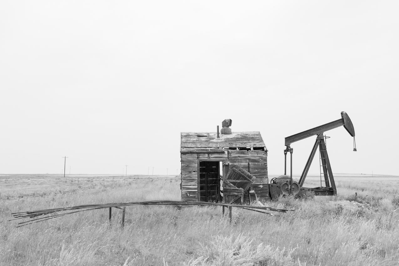
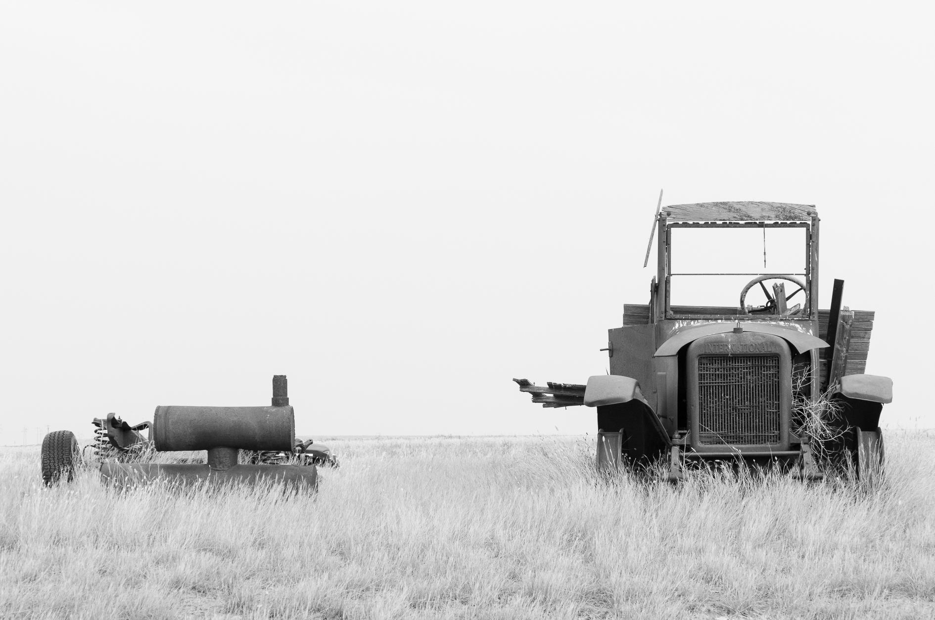
Orphaned Wells
Master’s Thesis
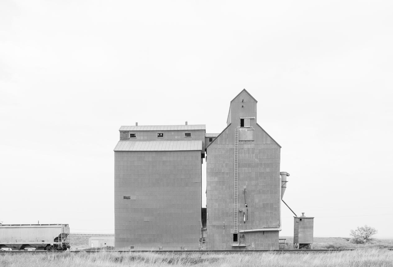
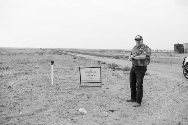
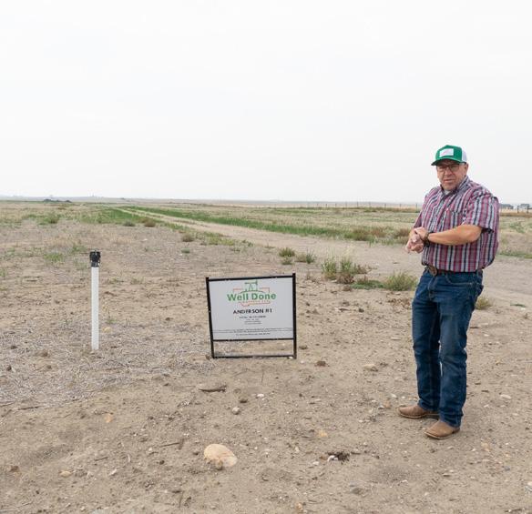
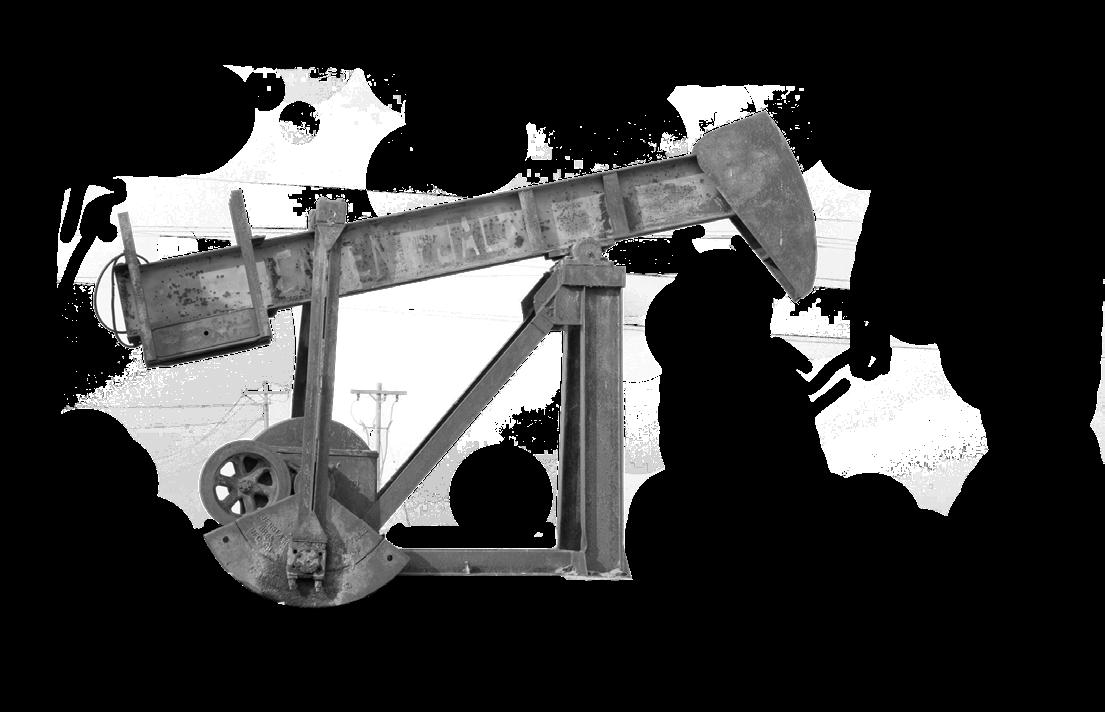
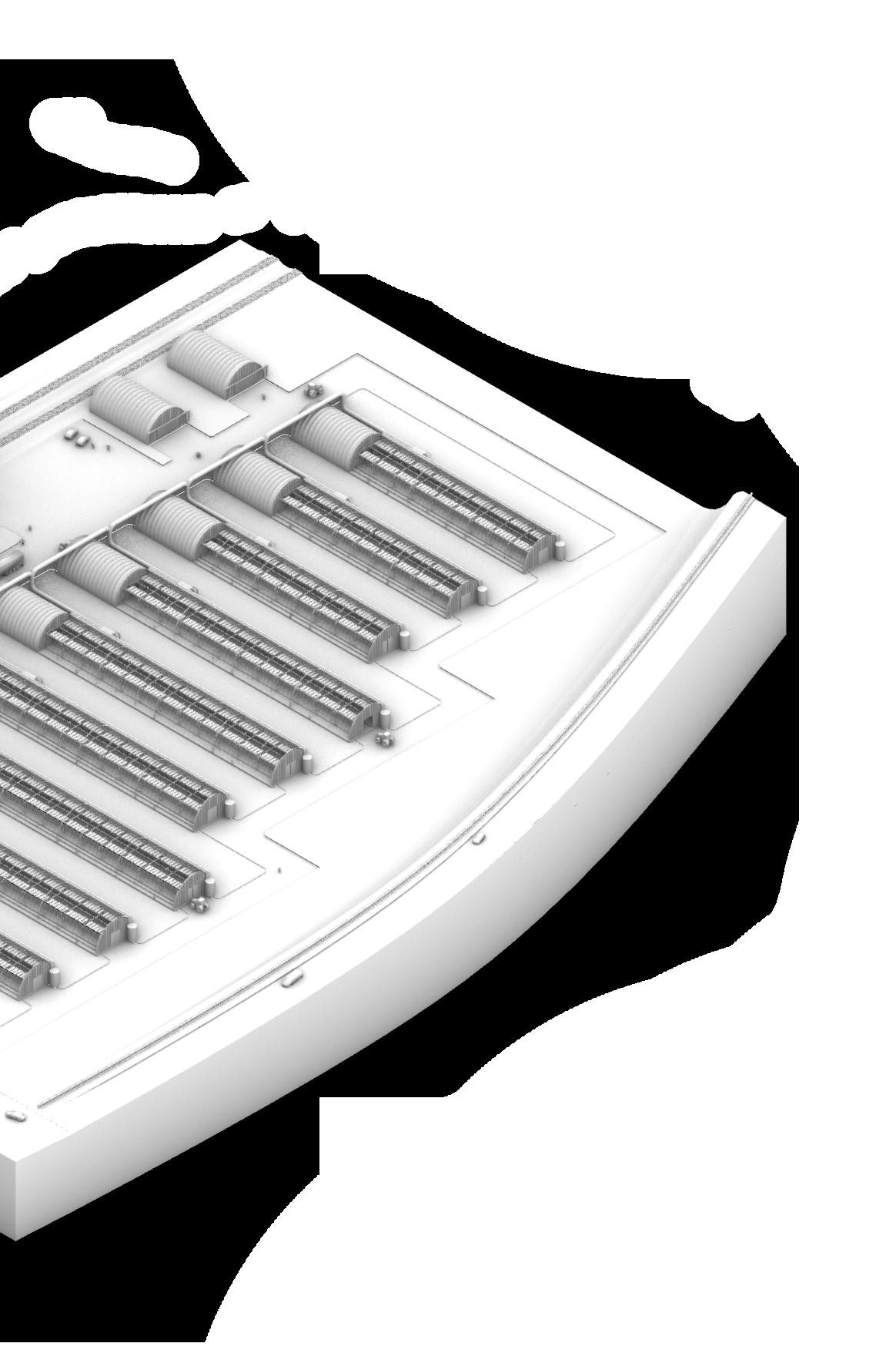
‘Orphaned oil wells’ are wells owned by oil and gas companies that have since gone bankrupt. These wells have been left largely uncapped, meaning methane is constantly released from the ground into the atmosphere via well pipe. This project works locally with the Well Done Foundation, a nonprofit dedicated to capping these wells, to explore ways to move beyond the status quo to turn a negative into a positive. After several months researching, mapping and photographing the wells, an architectural solution was born.
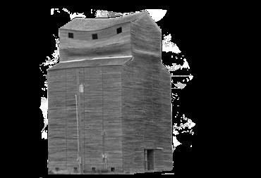
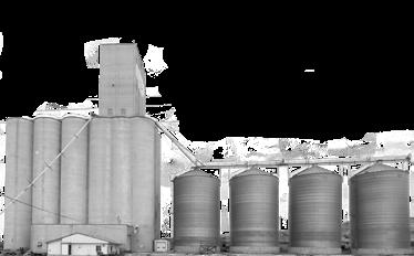
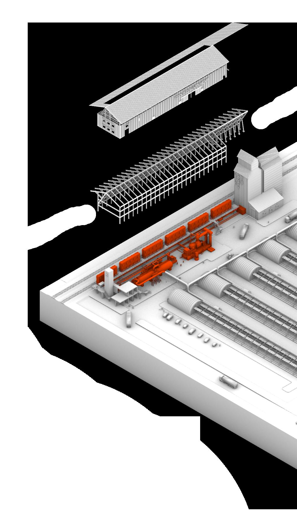
Emphasizing place making and program, it was decided based on historical heating practices that a small portion of the well emission in Toole County, Montana could be transported and utilized as a power source. These emissions would then be stored in now abandoned grain elevators before powering carbon capture fans through co-generation. After being removed from the atmosphere, the C02 would be used to facilitate hemp growth before allowing the plants to redistribute the gas into the ground. The hurd of the hemp would then be used in hempcrete to sustainability cap the remaining orphaned oil wells. Finally, the byproducts of the hemp would be sold to provide economic incentive and transported via rail throughout Montana.
20
Research + Mapping
There are 2.15 million unplugged abandoned wells in the U.S. in 31 states
That is the equivalent of:
1.29 million home’s electricity use for one year
1.54 million passenger vehicles drive for one year
The current well capping status quo presented by Well Done Foundation founder Curtis Schuck:
Combined, they emit 7.11 MMT co2e each year
7.85 billion lbs of coal burned
STEP THREE
02 03
Locating Through Shale Xp Excavation + Debris Removal Capping With Hempcrete
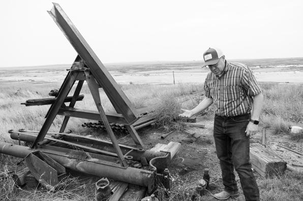
Hemp hurd is mixed with slurry and water to create “hempcrete,” which is used to surround the pipe. The hempcrete is biodegradable, crack resistant, and better suited
Contribute to the Study of Architecture Demonstrate
Research and Analysis
There are 2.15 million unplugged abandoned wells in the U.S. in 31 states across the country
one year
of
emit 7.11
year
1.54 million passenger vehicles drive for
798 million gallons
gasoline consumed Combined, they
MMT co2e each
of: 7.85 billion lbs of coal burned PRIORITIES 1.
critical architectural thinking 1.A Propose a solution to a problem 1.B Yield a new insight 1.C Introduce a new Process 1.A.1 Identify current challenges facing the field of architecture 1.A.3 Determine which local issues take precedent 1.A.2 Further our understanding of a problem 1.A.4 Conduct Research on the issue 1.A.5 Conduct Research on the issue 1.A.6 Offer ways to mitigate the problem through design 1.B.1 Explore a new topic 1.B.2 Combine topics previously unexplored together 1.B.3 Apply theories from different disciplines to expand the understanding of architecture 1.B.4 Develop a new approach to a typology 1.B.5 Apply an existing idea to a new location or context 1.C.1 Identify how new or improved processes of design can allow for innovations in problem solving 1.C.2 Integrate new technologies 1.C.3 Offer new modes of design thinking 1.C.4 Develop new methods of production 1.C.5 Bring new collaborations between fields 1.C.6 Find new ways to communicate design ideas 1.C.7 Create new approaches to working with particular groups/ stakeholders PROCESSES 2.
Identifying and Understanding 2.A Working with nonprofits in the community 2.B Looking towards precedents 2.C Developing site analysis 2.A.1 The “Well Done Foundation” which works towards capping orphaned oil wells 2.A.2 Oil companies go bankrupt, abandon wells after failing to pay deposit, leave wells uncapped 2.A.3 2-3 million uncapped oil wells in the United States constantly leaking methane and C02 2.A.6 Wells sterilize the ground, cost an average of $76,000 to reclaim ($30,000$1,000,000) 2.A.5 Each well leaks equivalent of 1500 cars driving non-stop annually 2.A.7 Highest density of wells found in Toole County, Montana 2.A.4 Alone, it would take Well Done 150,000 years to cap American wells at it’s current pace 2.A.8 Well pipes are cut, surrounded in hempcrete, and monitored to cap 2.B.1 climeworks carbon capture in Zurich, Switzerland 2.B.3 Engineering carbon capture plant in British Columbia 2.B.2 Lavender fields in coal country 2.B.4 “Orca” carbon capture plant in Reykjavik, Iceland 2.C.1 Highest density of wells found in Oilmont, Montana 2.C.2 Neighboring communities/ ghost towns of Shelby, Kevin, and Sunburst 2.C.3 Geological survey data from University of Montana 2.C.4 Well lease data and locations from oil database ShaleXP 2.C.5 US census data for local economy data 2.C.6 Historic accounts and background of the Great Northern Railroad 2.C.7 Natural systems data using 3d modeling with COVE tool INTERVENTIONS 3. Adapting Waste Emissions Creating a positive from a negative 3.A Redirecting Emissions 3.B Burning Emissions for Carbon Capture 3.C Captured Carbon used for byproducts 3.A.1 Rather than pouring concrete, pipe the gas to towns in Toole, County 3.A.2 Number of wells directed Dependant of size of grain elevator/ community 3.A.2 Store gas within unused, abandoned grain elevators 3.A.2 Establish program based of amount of gas each is able to store 3.B.1 Modular cogenerators (CHPs) used to create heat and electricity from gases 3.B.2 Modular carbon fan grid captures emissions from uncapped wells west of site 3.B.1 Compressed C02 stored within grain elevator or added program 3.B.1 Compressed C02 used in the creation of a byproduct for economic incentive 3.C.1 Create a closed loop system in which facilities communicate 3.C.2 Byproducts created based on needs of each community 3.C.3 Shelby, Montana creates biogas from anaerobic digester for agricultural equipment 3.C.4 Kevin, Montana creates Fertilizer for surrounding farmlands 3.C.5 Sunburst, Montana creates hemp for hempcrete to sustainably cap remaining wells 3.C.6 Carbon products are sold to create economic incentive 3.C.7 Byproducts and waste are able to be distributed and used by each facility 3.C.8 Jobs lost by oil industry are recreated 3.C.9 Sunburst, Montana focused on as example
access
well,
pipe.
That’s the equivalent
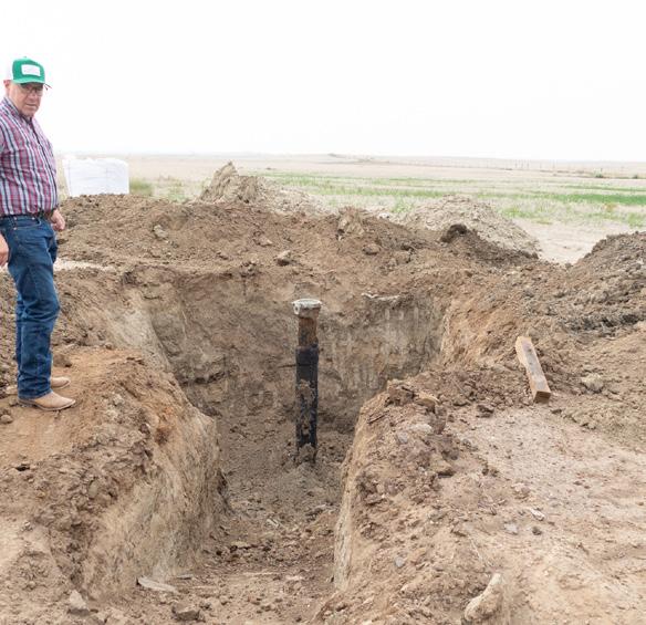
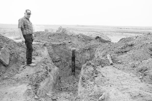
Permission is granted by landowners to
the
and 5’x5’x5’ hole is dug around the
The pipe is then filled with special concrete developed by researchers at Montana State University and Montana Tech.
01
25-101-05612 Shelton U.S. 22(-) Queen City Oil C0. Dry Hole 1926-05-03 Queen City Oil Co. Oil U.S. 18(-) Queen City Oil Co. Oil Corey 7(-) Corey 25-101-08868 1925-07-04 Corey Corey Oakley & Hayes Corey 1 Whitman-Sunburst Corey Corey 6(-) 25-101-08864 1926-04-19 Oil Gas 1925-05-13 Corey U.S. 19(-) Queen City Oil C0. Oil Queen City Oil C0. Oil 1948-12-24 Queen City Oil Co. Oil 25-101-08914 1927-07-01 Queen City Oil Co. U.S. 12(-) Queen City Oil Co. Federal 4 25-101-8912 Queen City Oil Co. 1925-05-20 25-101-08905 Norem Oakley & Hays Gas Norum 1(+) 25-101-08909 1926-05-28 Glenrock Oil Company 1923-12-12 Norum 1(+) 1925-07-03 Oil Oil 1924-09-07 Corey 6 Crumley-Sunburst Dry Hole Corner Oil Company Dry Hole Norum 4(+) Yealy, L.J. Gas Sunburt Oil Refining Co. Sunburt Oil & Refining Co. Dry Well Sunburt Oil & Refining Co. Oil Kipling Energy Incorporated Oil Govt. Storme 7 Corey 1(+) Govt. Storme 1(Van Meer Oil Corp. Govt. Storme 25-101-05554 1948-04-27 25-101-05554 Corey Newton McMurray Oil Corey Crumley-Sunburst Dry Hole Federal 4-2 Montana Pacific Oil Gas Co. Oil 25-101-22482 Kipling Energy Incorporated 1983-07-07 25-101-08825 Govt. Storme 3 Govt. Storme Oil Corey 3 25-101-08841 Corey Corey Crumley-Sunburst Corey A-1 Oakley Hays 25-101-08840 Corey Corey 2 Corey Corey 2 Crumley-Sunburst Corey Whitman-Sunburst 25-101-11354 Crumley-Sunburst Dry Hole 1925-09-11 25-101-22187 1981-08-31 1924-07-21 Queen City Oil 1924-06-19 Federal 4-4 25-101-08875 U.S. 8(-) Corey 3X(-) Johnson Oil Oil 25-101-08871 Dry Hole 1924-10-18 Queen City Oil Co. Oil 25-101-05588 Dry Hole 1949-10-07 25-101-08877 U.S. 5(-) U.S. 6(-) Queen City Oil Co. Queen City Oil C0. Oil KEVIN-SUNBURST OIL FIELD SUNBURST, MT Population: 360 2.03 sq miles Elevation: 3,369 SHELBY, MONTANA Population: 3,297 5.96 sq miles Elevation: 3,079 NORTHERN RAILROAD U.S H I G H W A Y 15 HIGHEST DENSITY OF ORPHANED WELLS IN MONTANA G R E A T N O R T H E R N R A I L R O A D OILMONT, MONTANA G R E A T 2,500’ 5,000’ 10,000’ 20,000’ KEVIN, MONTANA Population: 139 0.36 sq miles Elevation: 3,330 2 1 3 TOOLE COUNTY, MONTANA Population: 5,324 1,915 sq miles 363 Farms Covering 1,094,910 Acres Farmland By Use Cropland: 67% Pastureland: 31% Share Of Land By Type Crops: 80% Livestock: 20% CHOSEN SITE: 22
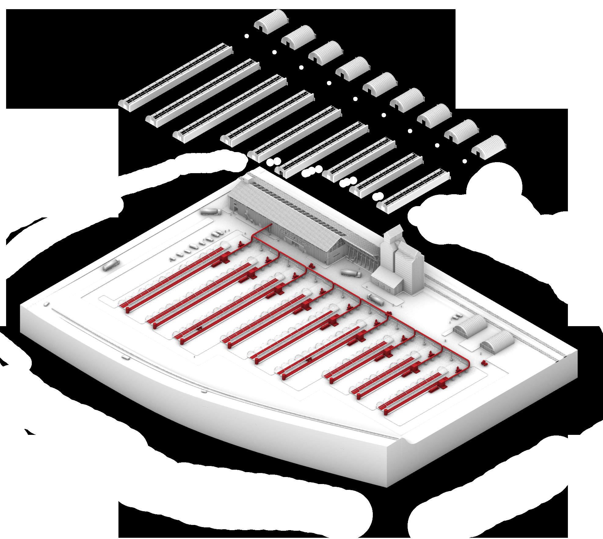
Response + Intervention
Piping, Storing, and Converting Waste Emissions at Grain Elevator Sites In Order to Power Carbon Capture Fans and Facilitate Hemp Growth for Create Hempcrete Needed For Capping Nearby Wells
Methane Storage
Waste methane is piped from Oilmont, Mt and stored within re-purposed grain elevators in Toole County
Stored methane is converted to electricity through co-generation in order to power carbon capture fans
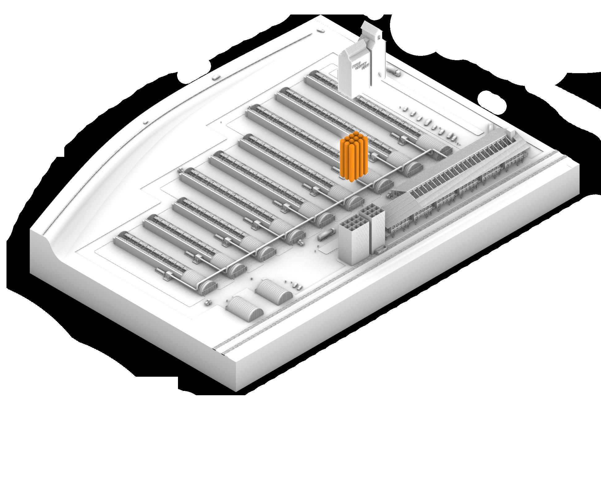
48’ 36’ 36’ 90’ 66’ 90’ 30’ 12’ 12’ 12’ 12’ 30’ 60’ 12’x12’x90’ = 12,960 X12 12’ 12’ 12’ 12’ 12’ 12’ 01 12,960
Carbon Capture 02
Hemp for Hempcrete 03
Captured carbon is distributed to greenhouses to facilitate the growth of hemp and the creation of hempcrete to cap remaining wells
24
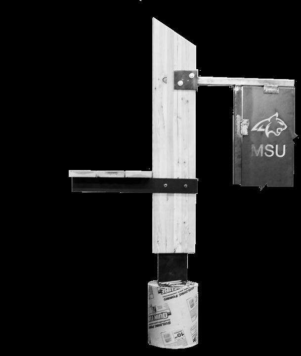
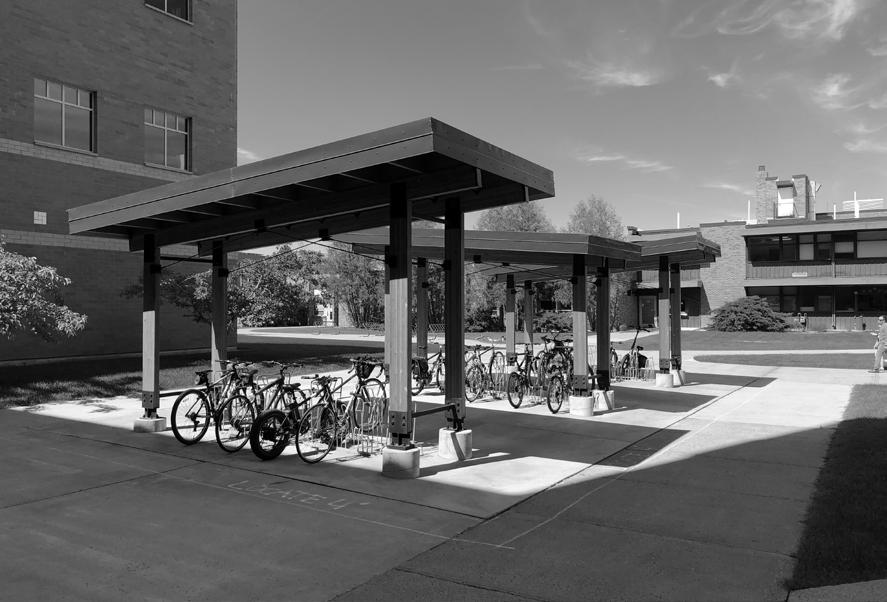
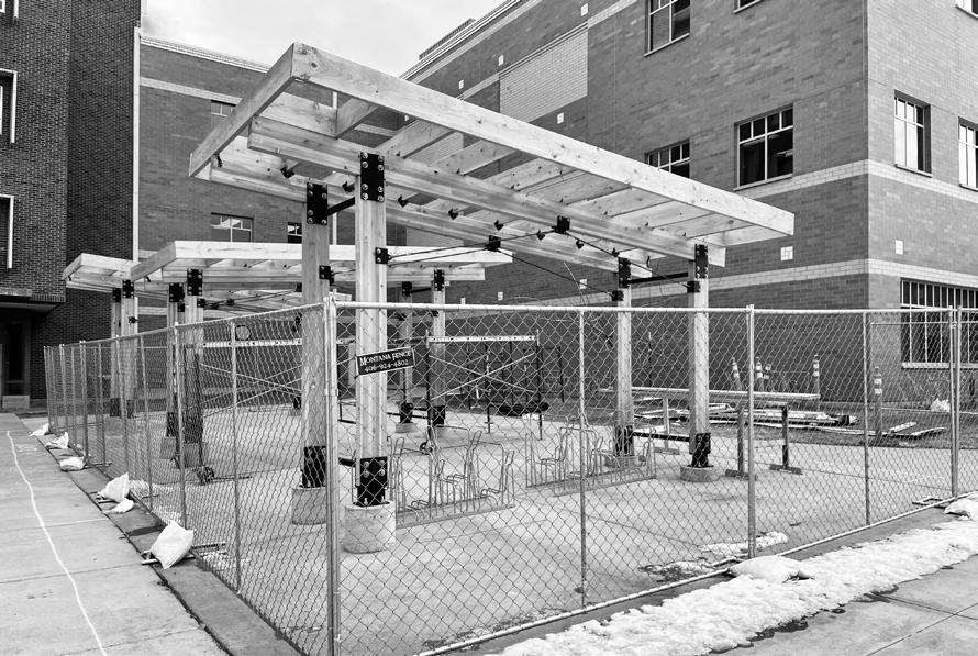
Bike Shelters
Design + Build
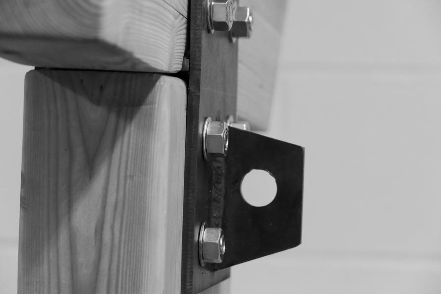
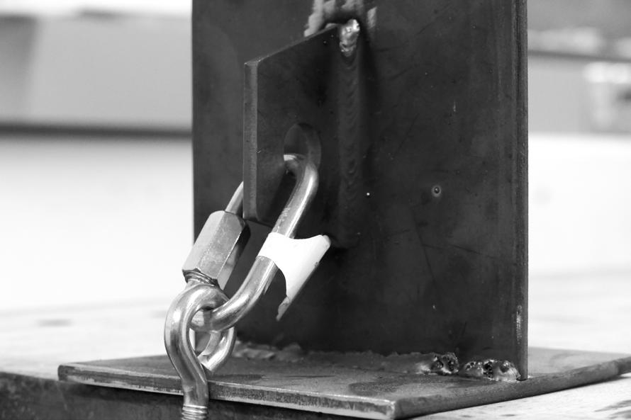
The Bike Shelters were a design/build project conducted by Montana State University M.Arch candidates taking place over two semesters by team of students in the M.Arch program at Montana State University. The process entailed everything from physical hand welded details to permit submittal with the City of Bozeman. Every drawing shown has was to be reviewed by engineers, faculty, and the city and is currently under construction by the students outside of Cobleigh Hall on MSU’s Campus.
The project provides much needed bicycle storage on campus, as well as protection from snow without jeopardizing the safety and security of the student population. Throughout the project we managed to remain below the budget of $25,000 for materials, with each shelter costing an estimated $4,000. If the shelters prove successful, the CD set will have continued use as a template for future structures across campus.
BIKE SHELTER
2 1/2" 2" 4 7/8" 2 1/2" 2" 4 7/8" 3 5/8" 3/8" PLATE STEEL STEEL STEEL 9 1/2" 1/4"3 5/8"1/4" 9" 3/8" 5 1/4" 3/8" 1/4" CORNER FILLET WELD 1/4" CORNER BEAD WELD 1/4" CORNER FILLET WELD 3/4"X8" EPOXIED ANCHOR BOLT 3/4" BOLT 2"X2"X1/4" TUBE STEEL SIMPSON H1 STRONGTIE 8d NAILS OR #9X1.5" SCREWS
BOLTS 1/4" PAINTED PLATE STEEL
P.T. RAFTER 2' O.C. 29 GA. STEEL CORRUGATED ROOFING 3.5"X9.5" GLULAM BEAM 3.5"X9.5" GLULAM COLUMN SIMPSON H2.5A STRONGTIE 8d NAILS OR #9X1.5" SCREWS BOTH SIDES OF BEAM -TYP. 1/2" BOLTS 2" #10 SELF TAPPING GALVANIZED/STAINLESS SCREW 16" O.C. 2"X2"X1/4" TUBE STEEL PAINTED FLASHING 1/2"-20 REVERSE THREADED DEEP DRAWER ADJUSTABLE YOKE END T.O. PIER 100'-0" B.O. COLUMN 100'-6" 2"X2"X1/4" TUBE STEEL PAINTED 1/4" PLATE STEEL PAINTED 3/4" BOLTS 3/8" PLATE STEEL PAINTED DRILL AND EPOXY 3/4" ANCHOR BOLT W/HILTI HY-200 AND 8" EMBEDMENT 3/8" PLATE STEEL PAINTED B.O. FOOTING 95'-0" #4 BAR -TYP. 3" 3" 9 3/4" 1'-0" 1'-0" 1'-0" 5 1/4" 3" MIN. 4'-0" MIN. DEPTH BELOW GRADE 1/4" PLATE STEEL 3/8" PLATE STEEL 1/2" BOLTS 1/2" THREADED ROD 1/2"-20 DEEP DRAWER ADJUSTABLE YOKE END 1/2" CLEVIS PIN 7" 1 1/8"7"1 1/8" #4 BAR -TYP. 9 1/4" R 1 1/2 " 2" MIN. COVER FOR STIRRUPS FLASHING DESIGN: REVISION NO. DATE KEY PLAN -(NTS) SHEET NUMBER DRAWING TITLE SCALE DATE ISSUANCE CHEEVER HALL 127, BOZEMAN, MONTANA 59715 406-994-6654 www.arch.montana.edu/ 1" = 1'-0" A8.0 4/13/2021 DESIGN DEVELOPEMENT BIKE SHELTER MONTANA STATE UNIVERSITY Cobleigh Hall, 119 Bozeman, MT 59717 DETAILS 8" 8" 1 1/4"5 1/2"1 1/4" 1 1/4"5 1/2"1 ø 13/16" ø 13/16" ø 13/16" ø 13 16" ø 13/16" ø 13/16" ø 13/16" ø 13/16 1/4" PLATE STEEL 1/4" PLATE STEEL ø 13/16 ø 13/1 ø 13/16" ø 13/16" ø 13/16" ø 13/16" 7 1/2" 1/4" 3 3/4" 2" 1 1/2" ø 9/16" ø 9/16 ø 9 16 ø 9/16" 4 1/4" 4 1/4" 5" 1" 3" 1" 1"3 1/4" 3 1/4"1" 3/4" BOLT 1/4" PLATE STEEL 1/4" FILLET WELD 1/4" PLATE STEEL 1/4" PLATE STEEL 1/2"-20 REVERSE THREADED STEEL TIE ROD 1/2" BOLTS 1/4" PLATE STEEL 3/8" PLATE STEEL 1/2"-20 REVERSE THREADED DEEP DRAWER ADJUSTABLE YOKE END 1/4" BEAD WELD 1/4" FILLET WELD INT. 1/4" BEAD 1/4" FILLET 1/2"-20 THREADED DEEP DRAWER ADJUSTABLE 1/2"-20 THREADED STEEL TIE 3/8" PLATE 1/4" PLATE 1/2" BOLTS 1/2" BOLTS 8" 8" 1" 3" 7" 3" 1" 1 1/4"5 1/2"1 1/4" 1 1/4"5 1/2"1 1/4" ø 13/16" ø 13/16" ø 13/16" ø 13/16 ø 13/16" ø 13/16" ø 13/16" ø 13/16" 1/4" PLATE STEEL 1/4" PLATE STEEL 8" 3 5/8" 1/4" PLATE STEEL ø 13/16 ø 13/16 ø 13/16" ø 13/16" ø 13/16" ø 13/16" ø 13/16" ø 13/16" 7 1/2" 1/4" 3 3/4" 2" 1 1/2" 3/4" 8" 3/4" 1/4" -TYP. COLUMN TOP RELIEF CUT FOR HORIZONTAL PLATE AT TOP OF COLUMN ø 9/16" ø 9/16 ø 9/16" ø 9/16" ø 9/16" 2 1/2" 1 1/2" 1 1/2" 3 5/8" 4 1/4" 4 1/4" 5" 1" 3" 1" 1"3 1/4" 3 1/4"1" 1 1/4"1 1/4" 5" 1 3/8" 1" 1" 4 1/4" 4 1/4" 6" 4 25/32" 6" 3 5/8" 6" DESIGN: REVISION NO. DATE KEY PLAN -(NTS) DRAWING TITLE SCALE DATE ISSUANCE CHEEVER HALL 127, BOZEMAN, MONTANA 59715 406-994-6654 www.arch.montana.edu/ 3" = 1'-0" 4/13/2021 DESIGN DEVELOPEMENT
MONTANA STATE UNIVERSITY
Hall, 119
MT 59717 FABRICATION DETAILS 3/4" BOLT 1/4" PLATE STEEL 1/4" FILLET WELD 1/4" PLATE STEEL 1/4" PLATE STEEL 1/4" PLATE STEEL 3/8" PLATE STEEL 1/2"-20 REVERSE THREADED STEEL TIE ROD 1/2" BOLTS 1/4" PLATE STEEL 3/8" PLATE STEEL
REVERSE THREADED DEEP DRAWER ADJUSTABLE YOKE END 1/4" BEAD WELD 1/4" FILLET WELD INT. 1/4" BEAD WELD 1/4" FILLET WELD INT. 1/2"-20 THREADED DEEP DRAWER ADJUSTABLE YOKE END 1/2"-20 THREADED STEEL TIE ROD 3/8" PLATE STEEL 1/4" PLATE STEL 1/2" BOLTS 1/2" BOLTS 26
3/4"
2X10
Cobleigh
Bozeman,
1/2"-20

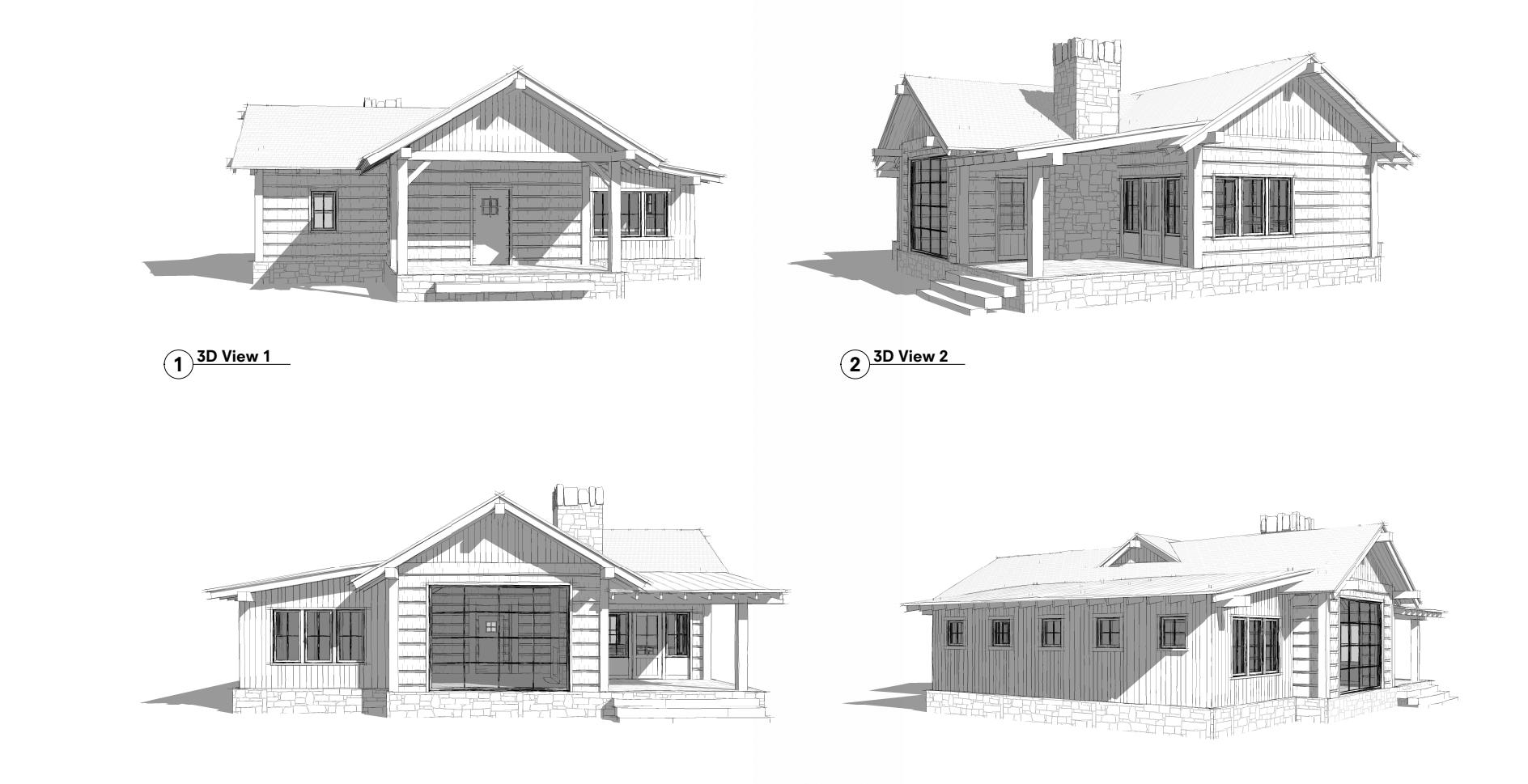
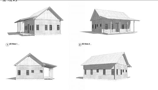
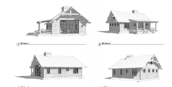
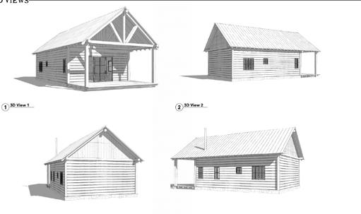
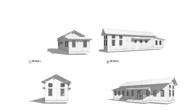
Faure Halvorsen
Internship
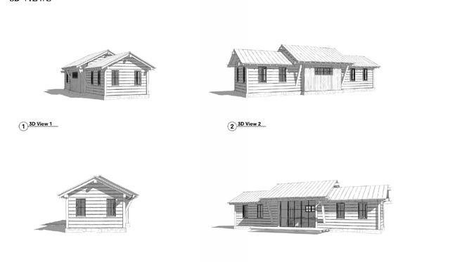
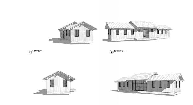
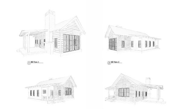
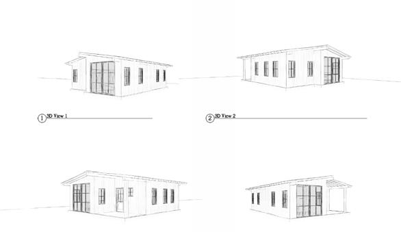
At Faure Halvorsen Architects as an Intern, I experienced both commercial and residential projects, both collaboratively and independently. Looking back, the most enjoyable and educational aspect of these projects would have to be a small fishing shack on the Jefferson River. Designed to be a guest house, the highly iterative and personal project was the first in which I was granted complete responsibility of schematic one-on-one design with the client. Under strict budgeting and square footage constraints, we worked alongside a clienthired general contractor. While frustrating at times, the fast pace and intimacy of the project, in addition to the opportunity for relative independence, proved to be a great and exciting learning experience. Featured are several of the iterations of the shack, each resulting from changing concepts and budgeting - the largest of these iterations being the design that ultimately was chosen and constructed.
28
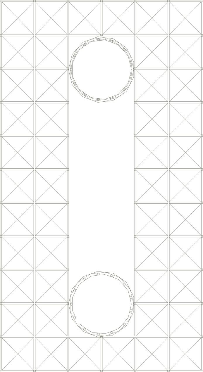
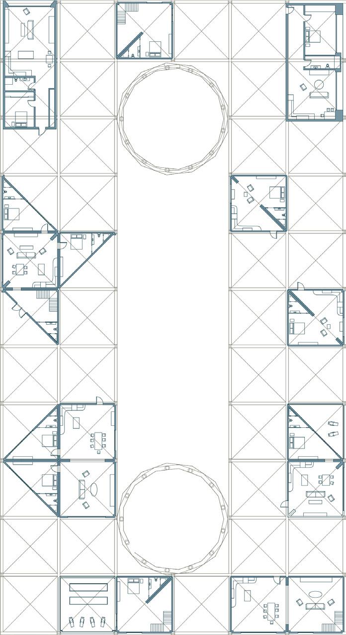
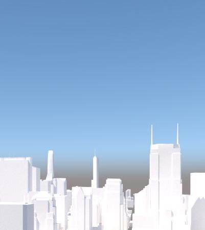
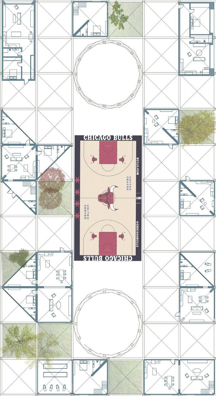
Villa Chicago Theory
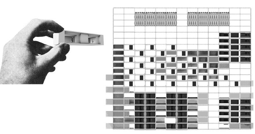
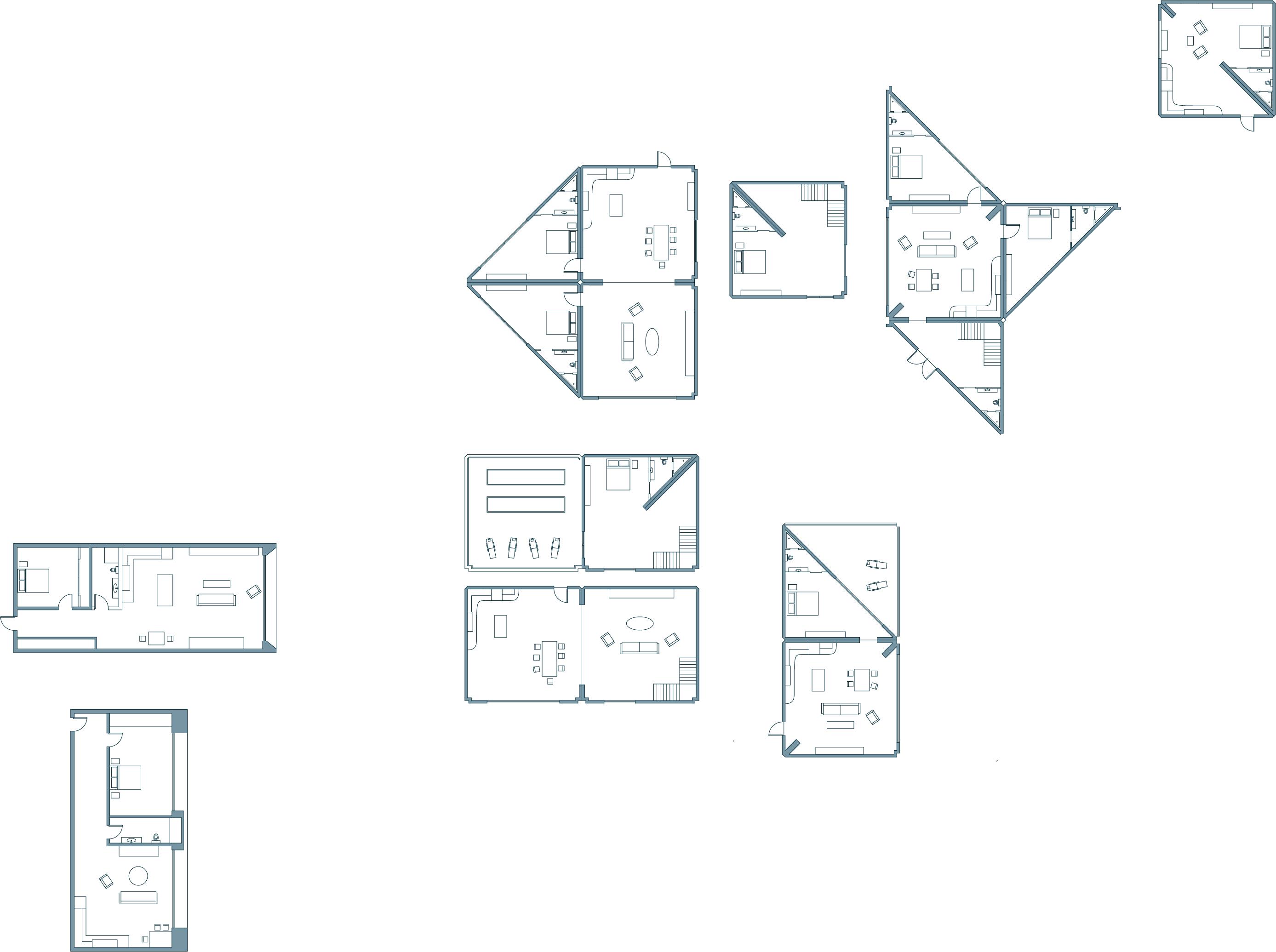
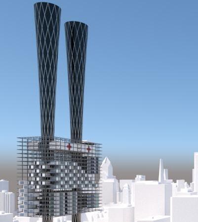
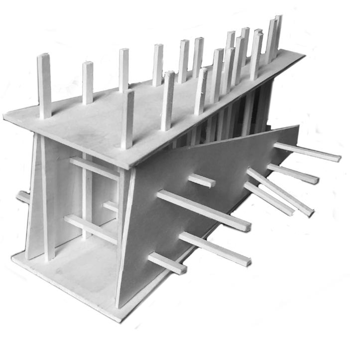
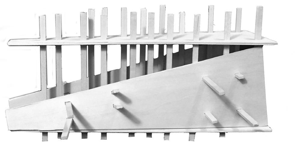
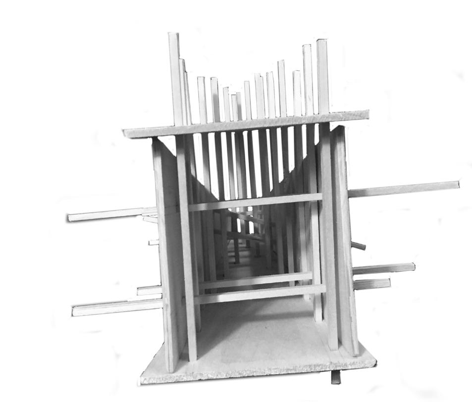
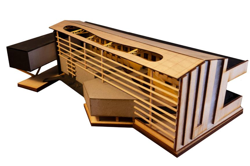
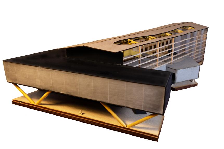
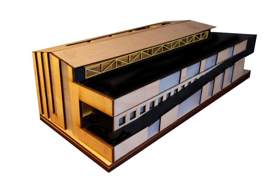
Inspired by the life work of the late Yona Friedman and his vision of ‘mobile architecture’ this studio project was completed in collaboration with Adrian Smith + Gordon Gill Architects during the beginning of the pandemic. Taking inspiration from works such as Le Corbusier’s ‘Dom-Ino’ House and Kisho Kurokawa’s Nakagin Capsule Tower, the overwhelming scale of the program drove me to experiment with the concepts of modularity, ‘space frames,’ and pre-fabrication during uncertain times which called for flexibility.
To the right are plans of a series of modules which are further complimented by images studying their designs playful integration into a steel frame grid. The suspension of this grid into the air by two cores is then used to examine reclamation of the urban ground level.
30
32
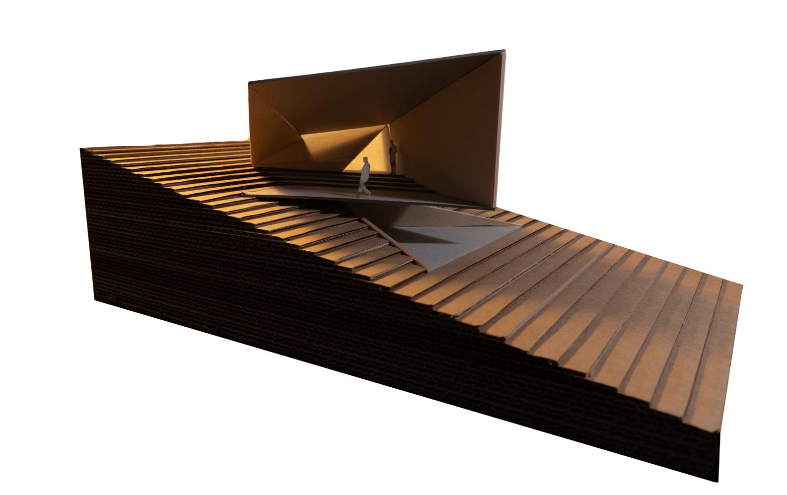
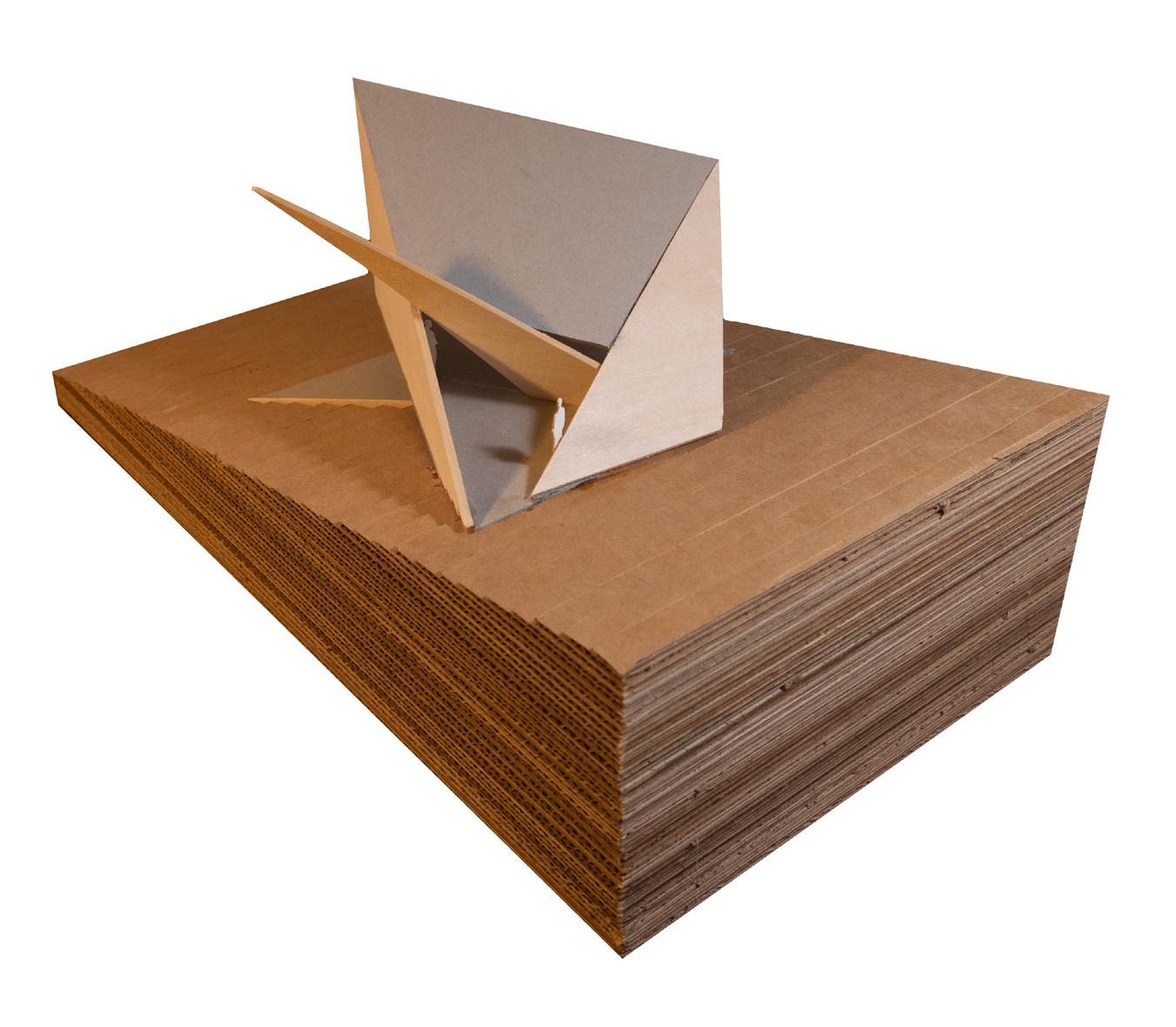
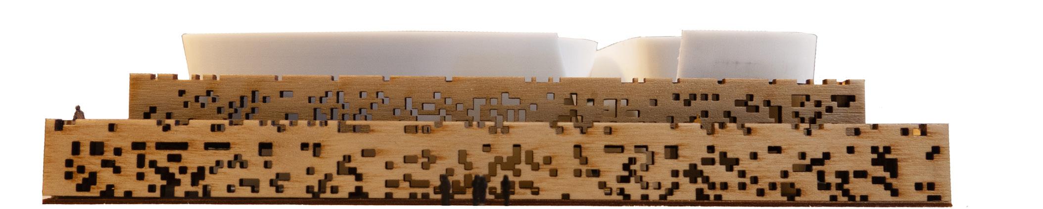
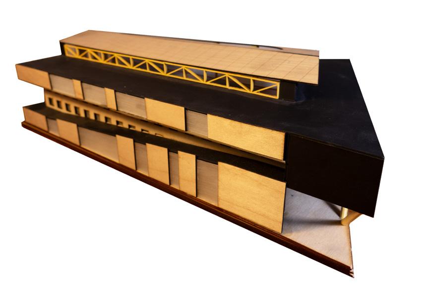
Objects Miscellaneous
My preferred method of communicating ideas throughout my education has always been the physical model. Apart from helping to formulate a better sense of scale and spatial quality, the progression of study models towards a final product documents a tactile and clear design progression. The following images showcase designs completed in various studios as well as an evolution in craft, playfulness, and construction.
34
36

williamleidolf@gmail.com (571) 232-9539
www.linkedin.com/in/williamleidolf1997/
