
CUT


CUT


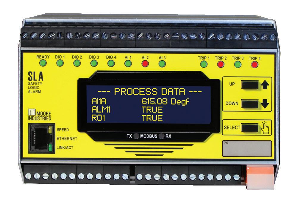
In the world of process safety, selecting and deploying logic solvers can feel like navigating a maze when burdened by complex programming, extensive documentation, and strict equipment ‘restrictions in use’. The Moore Industries SIL 3 capable SLA Multifunctional and Multiloop Logic Solver simplifies the path, removing these obstacles.
Designed with simplicity in mind, the SLA combines dynamic alarming and monitoring capabilities with powerful logic functions with a no-nonsense FDT/DTM simple and user-friendly programming interface. This makes configuring, simulating, testing and documenting a breeze — no complicated safety PLC-type programming is required.
Whether deploying a single SIF (Safety Instrumented Function) or solving a more intricate shutdown strategy, the SLA’s intuitive programming interface reduces engineering time and complexity. With 16 internal alarms and 17 I/O points on board, the SLA is suitable for tackling or augmenting any safety instrumented system (SIS) needs.
From emergency shutdown systems to alarm voting schemes, the SLA helps to provide the confidence needed when safety is on the line. Designed for the field and built with rugged Moore Industries reliability, it’s ready to perform in tough environments without the concerns that often arise with safety logic solvers destined for the comfort of control rooms.
With the SLA, you don’t just manage safety logic — you master it. Because in a maze of complexity, the straightest path is simple logic that works.


Now we are entering an age of artificial intelligence — with a mixture of hope and trepidation — we have to see the upside of what AI can do for our industrial systems.
Many ICS vendors and others are now actively promoting the use of AI in various areas, but the application that has advanced the most would have to be predictive maintenance. Not only can AI assists in the assessment of failure and maintenance prediction, but now generative AI can help make technically complex knowledge more accessible to operators and maintenance staff. Having a conversational assistant that can access site and plant history and relevant technical documentation not only speeds up time to problem resolution, but also helps to overcome the challenge of generational change in technical staff, as experienced engineers and technicians leave the profession.
I expect that before long, AI will also creep further into process instrumentation itself. We already have instrumentation that has built-in smart self-verification, reducing calibration effort — an example described in our article on magnetic flow meters. An instrument that has AI embedded and can self-adjust and warn of maintenance requirements may not be too far down the track.
Across both the IT and OT worlds, AI is also playing a huge role in issues of cybersecurity, but no matter how good AI gets at detecting and limiting cyber attacks, it will never be a replacement for good IT/OT network design that puts in place the necessary controls and roadblocks to prevent the spread of malicious activity. Guidance can be found in IEC 62443 as described in our final feature article this issue.
As always more detailed daily news and new automation products can be found on processonline.com.au, and by subscribing to our bi-weekly email newsletter.
Glenn Johnson Editor pt@wfmedia.com.au

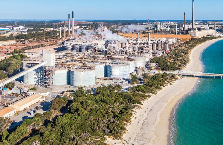
Alcoa has announced that it will permanently close its Kwinana alumina refinery in Western Australia. The company says it has undertaken numerous studies and analyses since curtailment to determine the future of the refinery, including restart and closure. Multiple factors led to the decision to permanently close the refinery, including the age of the facility, scale and operating costs, market conditions and bauxite grade challenges.
“Alcoa operated the Kwinana refinery for a number of years in a challenging environment and made the difficult decision to permanently close the facility after unsuccessfully exploring multiple options for a sustainable path to restarting,” said Matt Reed, Executive Vice President and Chief Operations Officer for Alcoa. “We appreciate the dedication and support of our Kwinana employees, contractors and suppliers who have made a major contribution to Western Australia’s economic development and prosperity over more than six decades.”
ARENA has announced over $12 million in funding to trial and demonstrate low emission technologies for process heat, reducing the reliance on natural gas for large manufacturers. Among those receiving funding are McCain Foods, Sugar Australia and Blackmores.
ARENA CEO Darren Miller said ARENA support through programs like the Industrial Transformation Stream remains vital in increasing the adoption of clean technologies in manufacturing.
“Achieving Australia’s emissions reduction goals requires that our energy-intensive industries and manufacturers develop and execute clear strategies to integrate renewable energy into their operations,” said ARENA CEO Darren Miller.
McCain Foods will implement two interconnected heat recovery systems at its Ballarat potato processing site: one system to recover high-temperature heat from condensate to decrease boiler demand, and a second to capture lower temperature fryer exhaust heat to produce hot water, which is then upgraded to steam.
Sugar Australia’s project aims to replace traditional natural gas evaporators with an electrically driven MVR system.
Blackmores plans to reduce emissions and energy consumption by replacing a natural gas boiler with a high-efficiency heat pump and a hot water buffer tank, and use renewable electricity and refrigeration condensate water as a heat source.
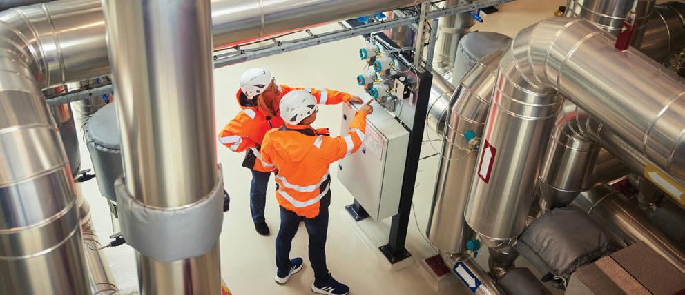
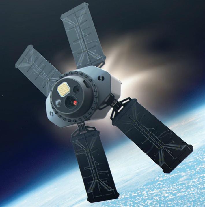
The NSW Government has announced a partnership with Australian space technology business Space Machines Company to establish Bradfield as a manufacturing hub for critical space infrastructure like satellites.
The Rapid Australian Production & Integration for Distributed Space (RAPID) agreement aims to bring advanced space technology manufacturing to Western Sydney. Space Machines Company will commence high-value manufacturing projects at the Advanced Manufacturing Readiness Facility (AMRF) this year, with the aim to develop hyperscale production capability to produce satellites that are used to repair other satellites in long-term orbit.
It’s expected the AMRF will support Space Machines Company to initially produce more than 30 units annually, with production expected to scale up to hundreds of units per year by 2030.
The government says it is also exploring opportunities for Space Machines Company at Bradfield’s second building and looking at establishing a dedicated hyperscale satellite production facility in Bradfield City.
The RAPID agreement also prioritises the development of a shared roadmap to build sovereign space manufacturing capability, open new market opportunities, and align with the strategic objectives of both the Australian and NSW Governments.

Generative AI can play a transformative role in predictive maintenance by providing deeper insights and advanced solutions.
Artificial intelligence (AI) has revolutionised various industries by enhancing efficiency and optimising processes. A key area where AI demonstrates significant potential is factory maintenance. Through their use in predictive maintenance, AI systems can anticipate and prevent machinery breakdowns, thereby reducing downtime and operational costs. In addition, the latest advancements in generative AI (GenAI) have made it easier than ever for factories to streamline their operations and overcome the daily challenges that prevent organisations reaching optimal efficiency.
Maintenance teams encounter numerous challenges that hinder their efficiency. Many team members are not data scientists and often struggle to interpret complex data, particularly when pressed for time or without access to expert guidance. Language barriers and the retirement of experienced engineers exacerbate the problem, leading to a loss of critical knowledge. Furthermore, the skills shortage and frequent job changes among the younger workforce make retaining and sharing knowledge increasingly difficult. Data is often inaccessible or difficult to reference, creating barriers to collaboration across multiple locations.
How generative AI addresses the challenges

GenAI addresses maintenance challenges by simplifying workflows and enhancing decision-making processes. It eliminates the need for team members to be data scientists, as the AI provides clear, actionable insights. Its user-friendly interface allows staff to ask questions directly, enabling quick, informed maintenance decisions.
Generative AI can play a transformative role in predictive maintenance, as large language models (LLMs) are designed to embed expert knowledge and provide insights based on vast datasets. Their impact can be broken down into two key areas:
• Expert knowledge integration: GenAI systems integrate extensive domain knowledge from reliability engineering and condition monitoring to provide detailed diagnostic insights. These AI models can process large volumes of historical records (and time series data in the future) to identify patterns and predict failures with minimal human intervention.
• Scalable solutions: By automating data analysis and diagnosis, GenAI enables predictive maintenance solutions to scale across multiple assets and industries.
GenAI is revolutionising predictive maintenance, addressing traditional challenges and paving the way for innovative solutions in the industry. >>
GenAI based on large language models –like ChatGPT – plays a significant role in understanding and processing textual data, which has traditionally been a challenge for machine learning and statistical techniques focused on numerical data, such as time series data from sensors. However, textual information often holds valuable insights into maintenance practices. This ability to derive meaningful information from minimal text input is beneficial, given that maintenance records are typically brief and lacking detail.
Leveraging minimal data for maximum impact
A common concern among organisations is the perceived lack of data to benefit from AI-driven predictive maintenance. However, even small amounts of data or brief maintenance records can provide substantial insights. Many organisations have a wealth of data within their controllers and existing systems that can be utilised effectively. The key is to harness this data, even if it is minimal, to start building an understanding of machine conditions and failure modes.
GenAI has proven impressive in its ability to infer detailed information from limited text. This means that organisations do not need to overhaul their maintenance processes or produce extensive reports for every maintenance ticket. Short and concise descriptions can be sufficient for AI to surface valuable knowledge and provide actionable insights.
The practical applications of generative AI in predictive maintenance are vast. One of the primary benefits is the ability to enhance prescriptive maintenance and knowledge capture. When a maintenance case is raised, AI can provide evidence and prescriptive guidance based on historical data patterns and past cases.
This includes potential root causes and recommended actions, with links to historical cases for further reference. This approach ensures that maintenance staff have access to relevant information without needing to sift through extensive records manually.
This aspect of AI involves providing actionable recommendations based on data analysis. For instance, when a sensor detects an anomaly, AI can correlate this data with past cases, identify potential causes, and suggest specific maintenance actions. This process reduces downtime and prevents minor issues from escalating into major problems.
Knowledge capture
AI can help in capturing and organising institutional knowledge, which is crucial as experienced technicians retire. By analysing maintenance records, AI can identify common issues and effective solutions, creating a repository of knowledge that can be accessed by less experienced staff.
Virtual maintenance assistance
GenAI-powered virtual maintenance assistance tools help teams make betterinformed maintenance decisions by using
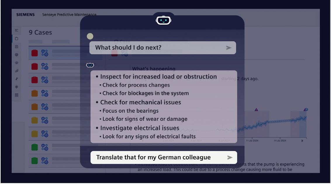
data to form in-depth knowledge of assets, provide instant answers to questions and retain all knowledge forever.
Virtual maintenance assistance tools can also potentially translate information into multiple languages and consolidate the knowledge of all maintenance staff. Capturing learnings as part of a team’s everyday workflow, they become an additional expert team member and a single source of truth — as well as learning and referencing all data sources, surfacing information when needed and bringing colleagues into the conversation seamlessly.
One of the latest developments in generative AI within predictive maintenance is conversational functionality integrated into PdM platforms. This feature will allow users to make ad hoc queries in natural language, enabling them to ask for summaries of maintenance activities or other specific information about an asset. The AI copilot will gather and summarise this information, making it easier for users to get the insights they need without navigating through multiple screens and records.
In the longer term, research is being conducted on applying the fundamental technologies of large language models to time series data. This approach shows promise in enhancing anomaly detection and forecasting, potentially leading to more accurate and reliable predictive maintenance systems.
Enhanced anomaly detection
By applying language model techniques to time series data, AI can improve its ability to detect anomalies. This involves not just recognising when data deviates from the norm but understanding the context and likely causes of such deviations. This can lead to faster and more accurate diagnoses of potential issues.
Advanced forecasting
AI can also enhance forecasting capabilities, predicting when a machine is likely to require maintenance based on historical data and current operating conditions. This proactive approach allows for better planning and resource allocation, ultimately leading to more efficient operations.
Sustainability in predictive maintenance extends beyond immediate operational benefits to encompass broader environmental and resource management goals:
• Upstream and downstream impacts: Predictive maintenance can help minimise waste throughout the entire supply chain, from production processes to product disposal.
• Resource efficiency: By optimising maintenance schedules and reducing equipment failures, predictive maintenance helps conserve resources and reduce the environmental impact of manufacturing processes.
• Remote monitoring: Digital and cloud-based solutions enable remote monitoring of equipment, reducing the need for onsite inspections and lowering the carbon footprint associated with maintenance activities.
Predictive maintenance, driven by advanced data analytics and AI technologies, represents a significant step forward in both operational efficiency and sustainability. By leveraging time series data, condition indicators and generative AI, businesses can achieve more accurate predictions, reduce downtime and support environmental sustainability.
One critical aspect of integrating generative AI into predictive maintenance is addressing
security and privacy concerns. Organisations are justifiably worried about their data being inadvertently exposed or used inappropriately. To mitigate these concerns, AI systems can be configured to operate within a secure cloud environment, where learning is turned off to prevent data from being shared or used outside the organisation.
Another layer of security involves anonymising data before it is processed by AI. This means removing or obfuscating personally identifiable information and other sensitive details, reducing the risk of data breaches.
As AI technologies become more prevalent, regulatory frameworks are essential to ensure their responsible use. Key regulatory considerations include:
• Transparency and accountability: Ensuring that AI-generated insights are clear and understandable, with transparency about the sources of data and the limitations of AI recommendations.
• Human oversight: AI systems should support human decision-making rather than replace it. Clear guidelines are necessary for how humans should interpret and act on AI-generated insights
• Ethical use of data: Regulations must ensure that data is used ethically and responsibly, protecting user privacy and ensuring that AI systems are not misused for harmful purposes.
THE BEST INDUSTRIAL CYBER DEFENCE STRATEGY IS TO PRESENT A UNIFIED FRONT AGAINST THREATS TO IT AND OT ASSETS BY ESTABLISHING A CONVERGED SOC THAT PROTECTS THESE ONCE SEPARATE TECHNOLOGY ENVIRONMENTS IN A HOLISTIC MANNER.
Generative AI is set to bring a radical shift in how predictive maintenance is conducted. By leveraging AI’s ability to process and understand both numerical and textual data, organisations can gain deeper insights and more effectively maintain their assets.
The focus on delivering value, ensuring security and maintaining usability will drive the successful integration of AI into predictive maintenance systems, ultimately leading to more efficient and reliable operations.
The future of predictive maintenance lies in the seamless integration of generative AI, which promises not only to enhance current practices but also to open new avenues for innovation and efficiency. As organisations continue to explore and adopt these technologies, the landscape of maintenance will undoubtedly evolve, bringing about a new era of precision and reliability in industrial operations.
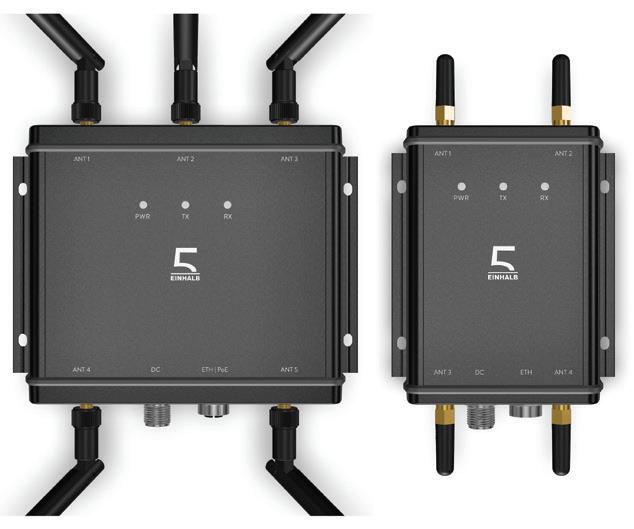
The German BlitzFunk is a real-time WLAN system with zero-latency roaming for high-mobility applications.
TE Automation Pty Ltd
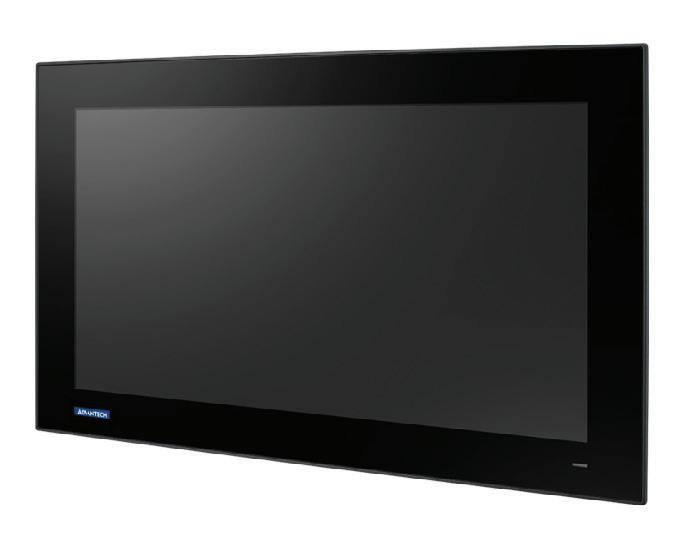
The SPC-618WE RPL is an explosion-proof touch panel computer with both IECEx/ATEX Zone and Class I Division II (C1D2) certifications.
Advantech Australia Pty Ltd
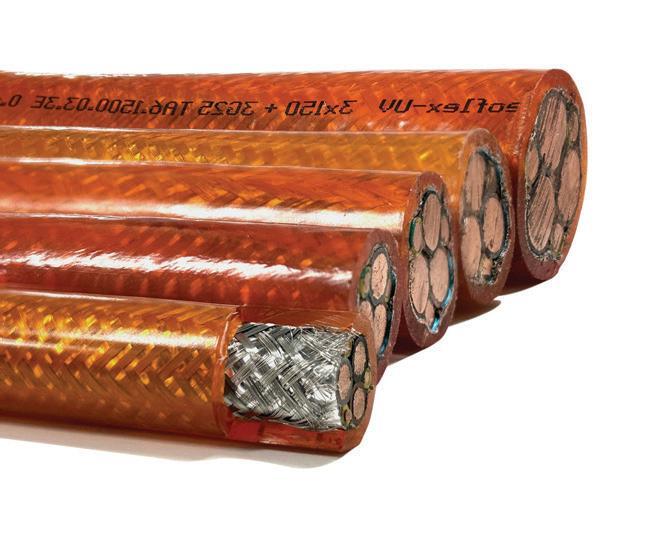
The Treoflex TA6 EMC-UV cable from Treotham is a highperformance motor cable designed for variable-frequency drive (VFD) applications.
Treotham Automation Pty Ltd
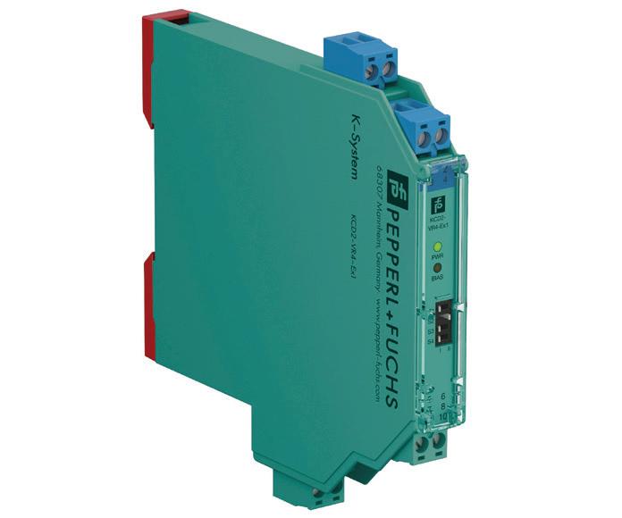
The KCD2-VR4-Ex1 isolated barrier is designed for use in real-time condition monitoring of machine bearings in hazardous areas. Pepperl+Fuchs (Aust) Pty Ltd
Southern Water, which serves more than four million customers in the water-scarce south-east of England, has been working towards a 15% leakage reduction by 2025 and a long-term plan to more than halve leakage by 2050 through a combination of new technologies and enhanced monitoring.
In November 2020, Southern Water began a project with technology company Ovarro to undertake targeted leakage reduction in 40 district metered areas (DMAs) across its region of Kent, Sussex, Hampshire and the Isle of Wight.
To achieve its goals, Southern Water deployed Ovarro’s LeakNavigator to enhance leak detection. The solution integrates Enigma acoustic loggers, the LeakInsight analytics platform, and expert analysis. Ovarro assisted by planning logger networks, supporting installations and analysing data to identify leaks, generating actionable points of interest (POIs).
About 1650 loggers, primarily the Enigma3-BB hydrophone sensor, were installed due to their easy deployment in meter boxes and effectiveness in detecting leaks on plastic pipes. Southern Water said that LeakNavigator’s tailored approach and advanced technology addressed the challenges of plastic pipelines, providing accurate, efficient and scalable leak detection.

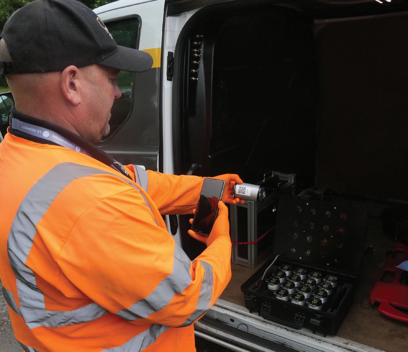
In the early weeks of the project, approximately 12 leaks were detected per month. Knowing the figure could be improved, Ovarro analyst Chris Mould reassessed each DMA and set specific individual filters using the LeakInsight software.
Additional training in the system and POI follow-up process was also given to leakage technicians onsite.
“Having used Ovarro leakage products for a number of years, we were confident that LeakNavigator would deliver good results in the DMAs we were targeting,” said Phil Tapping, Regional Operations Leakage Manager at Southern Water. “After some initial training and guidance, the overall end-to-end process was straightforward, and we are pleased with the outcomes to date.”
Following the training, technicians began to find more leaks, much faster — rising from around 12 per month to approximately 130 — and they gained greater confidence in the accuracy of the POIs. Up to July 2024, a total of 1170 leaks and 66 burst mains had been found.
An overall conversion rate of 80% was recorded for category 1 alerts, for which the data indicated a strong likelihood of a leak being found. Leakage in 35 of the 47 DMAs had reduced, with an overall reduction of 51 m3 in water loss across all DMAs. This equates to 204 ML per day of water being saved. Targets in 16 DMAs had been met, with the project ongoing. In June 2024, two further large leaks were picked up by the system, both on communication pipes. The first repair saw the nightline reduce from 15 m3 per day to nine. The second repair brought
a further reduction which took the DMA nightline down to 3 m3 per day.
During the project, there were some significant successes. In April 2024, LeakNavigator detected two main bursts in one DMA in the town of Andover in Hampshire, where leakage had been increasing for approximately 12 months. Earlier attempts to pinpoint the leak had proved challenging — in part due to a pressure-reducing valve emitting constant sound and an oval-shaped water main pipeline that reverberated all sound waves.
On following up the POIs, with close guidance from Ovarro’s analysts, technicians found two large bursts, one on a plastic pipe and one on metal, both likely to have been running since at least January 2024. Following repairs, the nightline figure for the DMA reduced by 13.5 m3/h.
Using previous methods of leak detection, the leaks were likely to have continued to go undetected until they became visible at the ground’s surface.
“Key to the success of this project has been close communications between Ovarro, our client Southern Water, and the technicians who are following the LeakNavigator process in the field every day,” Mould said.
“We are aiming to reduce leakage by 53% by 2050 — a target greater than the 50% reduction set by the government. New technology, like LeakNavigator, is a key part of our strategy,” Tapping said.
Ovarro
ovarro.com
Bill Sholette*
Condensation, build-up, obstructions and silt can cause difficulties in making reliable level measurements in lift station wet wells.
Lift stations pump water and wastewater from a lower to higher elevation to compensate for topographical changes. Most processing facilities are fed by gravity flow of the water and wastewater, so in locations where a change in elevation prevents gravity feed, lift stations pump the water to a higher elevation to increase the hydraulic head in order to provide reliable gravity flow into the facility.
Water level in the lift station wet well or reservoir needs to be monitored to provide input to the pump (Figure 1), which pumps water out when it reaches a pre-determined level. The level measurement also turns off the pump at a minimum level to prevent run-dry damage.
Wet wells can be a difficult environment for instrumentation due to the high humidity and condensation typically present. Heavy coatings and vapours can be found in sewage wet wells, which are capable of coating or corroding mechanical level measurement devices and leaving them inoperable. In these situations, technologies that do not contact the material being measured should be considered.
Historically, level measurement in lift station wet wells has utilised several technologies, including floats, submersible
hydrostatic instruments and non-contact ultrasonic instruments. These technologies can be effective when properly selected and maintained, so let’s take a look at each and consider the positive and negative points.
For decades, float switches have been used for wet well level measurement. The advantages of float switches are low cost and simple operation. Typically, two or more floats are used, with one acting as a
high-level pump-on and another float acting as a low-level pump-off indication. While floats have advantages in cost and simplicity, they can fall short in several ways.
Depending on the type of float, the linkage or cable tether can foul or hang up. Floats can sometimes also leak causing a loss of buoyancy. In wastewater applications, build-up on the float can cause it to sink. When using floats for wet well applications, regular maintenance is extremely important to ensure proper operation.
Level switches are often used as a high-level back-up for a continuous level
transmitter to indicate if the level reaches a point where the well is close to overflowing. Since the high-level switch is only reached in ‘upset’ conditions, floats work fairly well as a high-level switch.
In contrast, submersible hydrostatic level transmitters operate on the head pressure of the water. A diaphragm in the transmitter is subjected to the water column on one side and referenced to atmosphere on the other side. Increases and decreases in level deform the diaphragm and cause changes in a capacitance bridge circuit, which is then converted to an output.
Submersible transmitters have several advantages. Firstly, they can be preselected for the applicable range of level measurement: for example, the transmitter may be ranged from 0 to 10 m of water, and since they are pre-ranged, no calibration is required. Submersible transmitters also have no moving parts to hang up or wear out. Still, it is important to make sure the diaphragm does not become clogged with silt or other solids as clogging will affect accuracy. A heavy build-up can prevent the diaphragm from reacting to changes in water level. When using submersible transmitters in applications where silt or solids are present, it is necessary to choose a transmitter able to tolerate these applications. A transmitter designed for water with solids will have a cover over the diaphragm that allows for easy cleaning, but it is important not to damage the diaphragm when cleaning.
WET WELLS CAN BE A DIFFICULT ENVIRONMENT FOR INSTRUMENTATION
DUE TO THE HIGH HUMIDITY AND CONDENSATION TYPICALLY PRESENT.
Ultrasonic instruments are another common technology used to measure wet well water level. Ultrasonic instruments operate based on the time of flight (ToF) principle: an acoustic pulse is sent to the surface of the water being measured and reflected back. The time it takes to reach the water and return provides the distance to the water, which is then converted into a level signal. One of the big advantages of ultrasonic level devices is that they are non-contact: the transducer sending the acoustic pulse does not come in contact with the water, providing a cleaner application for sewage wet wells.
However, ultrasonic instruments are also not immune to problems. The humid conditions in a wet well can cause condensation to form on the face of
the transducer, which can attenuate the acoustic energy, limiting the range. In some cases, it can even cause a near-field fault. Confusing acoustic reflections caused by structures in the wet well such as ladders, pump columns, cables, etc, must also be taken into consideration and avoided or mapped out if the ultrasonic device being used offers this feature.
Another concern is splashing on the transducer, which can leave residue able to attenuate the acoustic energy, requiring cleaning. In sewage wet wells, where methane can be present, ultrasonic instruments experience another problem: the speed of sound is faster in methane than it is in air. This will cause errors in the level measurement, resulting in the level appearing higher than it actually is.
A more recent trend in level measurement for lift station wet wells is the use of radar technology. In the past, radar transmitters were considered too expensive for use in wet wells, but recent developments in electronics have allowed for lower-cost offerings.
Radar transmitters offer a number of advantages over traditional wet well level technologies. First, like the ultrasonic instrument, radar is a non-contact technology using the time of flight measurement principle. With radar, an electromagnetic pulse is directed to the surface of the material being measured and the energy is reflected by the different dielectric constant of the water compared to air. Similar to ultrasonic instruments, the time taken to reach the water surface and the reflection to return are measured, providing a distance to the surface of the water which is then used to calculate the level.
Along with the advantages of noncontact measurement, the transmission of electromagnetic energy is not affected by vapours or steam in the air space above the water, which is a distinct advantage over ultrasonic level technology.
New radar antenna designs provide wetted parts of Teflon with a concave surface. These concave antennas are designed to shed condensation build-up on the antenna face, preventing attenuation of the electromagnetic signal. In sewage wet well applications, the Teflon helps to prevent material from adhering to the antenna when water splashes solids.
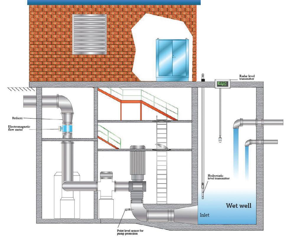
When selecting a radar unit for mounting inside a wet well vault it is important to remember the transmitter may experience submersion in extreme conditions. For this reason, selecting an encapsulated transmitter that meets IP68 (protected against temporary immersion) is recommended.
One of the great advances in new radar units is the simplicity of commissioning and mapping. With all modern radar transmitters, accessing the setup program can be made via Bluetooth and executed on a smart phone or tablet (Figure 2). This is a great advantage over older units that required commissioning through a pushbutton, an HMI interface or opening the housing and connecting a cable to a laptop with a modem.
In many cases the radar transmitter may be located in an installation that is difficult to access. This is particularly true of water and sewage wet wells where the radar may be inside a concrete vault. Trying to reach these units for access to the HMI or to connect a cable to a modem may require a confined space permit. With Bluetooth it is a simple matter of opening the access lid in most cases.
The latest radar technology also offers sophisticated mapping programs that allow the transmitter to ignore internal obstructions such as ladders, pump columns,
cables and baffles. While these mapping programs are sophisticated, they are much easier to implement than previous mapping programs from even a few years ago. If the wet well is empty or the level is at its lowest point, simply executing the mapping routine is all that is required. The radar transmitter does all the work. In situations where the tank is not empty, you need to determine where the level is and then map to a few centimetres above the actual level.
There are a number of ways to measure the water level in lift station wet wells. Selecting the technology able to provide the most reliable level measurement with the least maintenance should be the goal. While traditional technologies, such as submersible hydrostatic and ultrasonic instruments can provide a reliable measurement, the new lower-cost radar transmitters now available in the market should be considered for these applications. The advantages gained in performance and reliability along with the ease of commissioning are significant.
*Bill Sholette is the Northeast Region level product manager for Endress+Hauser USA. He is responsible for technology application and development of level products, and has published a number of white papers and articles pertaining to level instrumentation. Sholette received his certification in management and marketing at Villanova University.

Allied Telesis industrial Ethernet switches are built with IP30-rated metal enclosures, wide operating temperature ranges (-40°C to +75°C), and fanless, DIN-rail mountable designs, making them suitable for the physical challenges of industrial sites.
The switches feature Allied Telesis Autonomous Management Framework (AMF) and Ethernet Protection Switching Ring (EPSRing) to offer fault tolerance and rapid network recovery, with EPSRing providing sub-50 ms failover.
The range offers unmanaged models for simple installations up to Layer 3 managed switches, and supports Gigabit and 10-Gigabit uplinks, and PoE/PoE+ for powering field devices, as well as security features including IEEE 802.1X, port security and access control lists (ACLs). The switches also support Modbus/TCP, SNMP and industrial protocols like Profinet for integration into existing systems.
The AlliedWare Plus operating system offers a consistent interface across the switch range, enabling engineers to streamline configuration, monitoring and troubleshooting.
LAPP Australia Pty Ltd lappaustralia.com.au
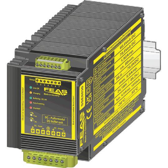
FEAS GmbH is expanding its SSE30 DC UPS series with the addition of the 60 V SSE6030 model, offering a supercapacitor solution for industrial 24, 48 and 60 V systems. The module is designed to enable uninterruptible power supply in demanding DC voltage applications.
The core feature of the SSE3060 is the complete elimination of batteries: supercapacitor technology allows maintenancefree operation in extreme environmental conditions (–30 to +55°C) and high power density in a compact design.
The SSE6030 stores 24.1 Wh (86.2 kJ) and typically offers 158 seconds of buffer time at 4 A current draw — sufficient for controlled shutdowns or emergency power switching. Due to its aluminium housing and full encapsulation, the SSE series offers a high degree of protection against environmental influences such as moisture, vibrations, etc, making it suitable for harsh industrial environments.
Automated Control Pty Ltd www.automatedcontrol.com.au


The Rosemount 3144S temperature transmitter offers a 0.05°C accuracy that is needed for processes that require the highest measurement performance. It is also available with an optional 20-year stability specification and a 20-year limited warranty.
Emerson’s ReadyConnect technology allows ease-of-use by enabling plug-and-play sensor configuration with a push of a button, eliminating the need to manually input sensor information and Callendar-Van Dusen coefficients, saving configuration and commissioning time.
An operator interface with a simplified, task-based menu and common navigation structure across host and configuration tools also allows further ease-of-use. Quick Service buttons provide local access to basic commissioning and maintenance tasks, such as viewing the current configuration, performing a loop test and rotating the display. Bluetooth wireless technology provides remote access to the device at distances up to 15 m for increased productivity, reliability and safety.
To address thermowell challenges, the Rosemount 3144S temperature transmitter expands the application coverage of Rosemount X-well Technology, Emerson’s non-intrusive measurement solution, which can now measure up to 650°C.
A Loop Integrity diagnostic performs continuous monitoring of the entire electrical loop to detect potential failures before they occur, while RTD Measurement Protection will seamlessly switch from a 4-wire to a 3-wire RTD sensor input configuration if one of the four sensor wires becomes broken, corroded or loose anywhere from the sensor element to the transmitter terminal connections.
Emerson www.emerson.com/au/automation
Colour sensors detect the colour of an object or print mark and compare it to a set reference value. They are a cost-effective and compact alternative to image processing systems and are suitable for many industries including mechanical engineering as well as the plastics, pharmaceutical and packaging industries.

The Leuze CRT 648 colour sensors are designed to be easy and intuitive to operate with a large, integrated LC display with keypad. The status of the switching outputs, a current colour value output or the signal quality can be displayed as selected. If different product variants are tested in one system, up to seven colour settings can be saved on the sensor and tested simultaneously. The large operating range opens up further possibilities. This means that one sensor can be used for different tasks, reducing the need for additional sensors and set-up times.
The CRT 648-32.G colour sensors are equipped with a polarisation filter to improve the reliability of detection on glossy objects. The evaluation of an object’s brightness, depending on its distance from the sensor, poses a further colour recognition challenge, so the CRT 648 colour sensors’ brightness evaluation with autocorrect provides distance-independent colour detection up to 65 mm.
Leuze electronic Pty Ltd www.leuze.com.au
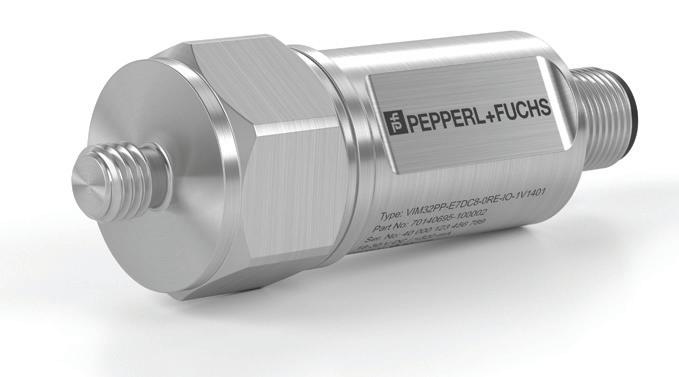
Pepperl+Fuchs has developed the VIM3 12 kHz vibration sensor, engineered to deliver precision in condition monitoring applications. With a sampling rate of 64 kHz, the sensor is capable of capturing up to 12,000 vibrations per second, resulting in 64,000 measurement points every second. The high resolution provides a basis for accurate FFT analysis.
Instead of relying on cyclical IO-Link transmission, the VIM3 12 kHz uses IO-Link BLOB (Binary Large Object) transfer to manage the large volume of data generated. The sensor records raw acceleration data and stores it in its internal memory before transmitting it in structured packets via IO-Link. This method prevents excessive loading of system RAM, enabling smooth data handling and consistent system performance, even with very large datasets.
The combination of high-speed sampling and efficient data transmission makes the VIM3 12 kHz a suitable tool for condition monitoring and predictive maintenance strategies.
Pepperl+Fuchs (Aust) Pty Ltd
www.pepperl-fuchs.com
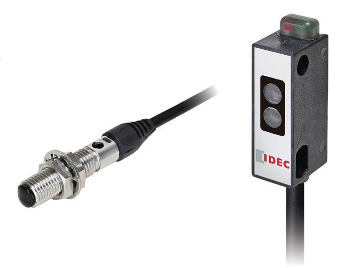
IDEC Corporation has expanded its photoelectric sensor range with the SA1N series of space-saving subminiature PE sensors.
For industrial equipment, the intersecting trends of increasing automation and reduced installation space mean that designers need compact and high-performance technologies for discrete sensing applications. General-purpose sensors simply don’t fit, and other technologies such as fibre optic devices are more costly and require separate amplifiers which complicate installation requirements.
The SA1N subminiature sensors are available in two versions: a barrel-mount fibre-type diffuse-reflective infrared LED style, secured with M6 nuts through a mounting hole; and a block-type convergent-reflective red LED sensor, secured with two mounting holes located at a 14 mm pitch.
Both versions are all-in-one devices with built-in amplifiers and sensitivity adjustment control. The barrel-mount version has a 3-50 mm sensing range, while the block-type can detect over a 5-30 mm sensing range. Both models are available in NPN or PNP light-on configurations, and both provide a rapid 0.5 ms maximum response time.
The sensors each come with flexible 2 m pigtail wiring, functioning at standard 24 VDC with minimal current draw. They operate over a wide -25°C to +55°C temperature range. The barrel-mount version uses a stainless steel housing and plastic encapsulation to achieve an IP67 rating, while the block-type is rated at IP64.
IDEC Australia Pty Ltd
www.idec.com/australia
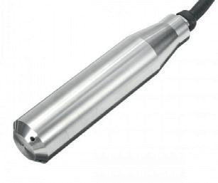
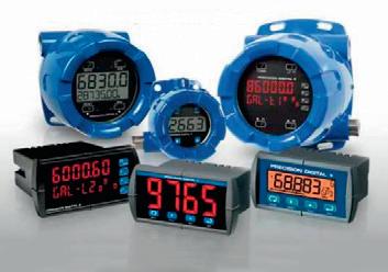
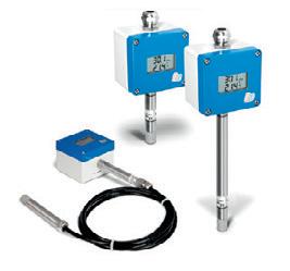
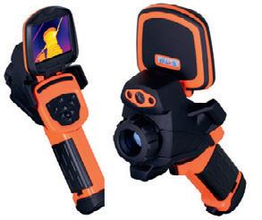
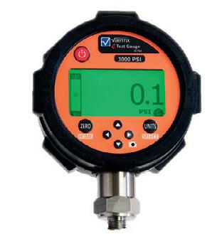
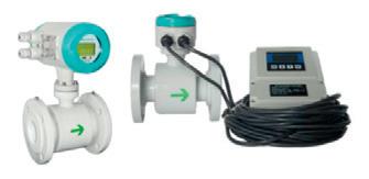
We specialise in Industrial Test & Measurement Sensors/Transducers: Pressure, Temperature, Laser Displacement, Flowmeters, Water Meters, Pneumatic Controls, Joysticks, Rotary Encoders, Accelerometers and LVDTs
Instrumentation: Dataloggers, DAQ Systems and Digital Display Units.

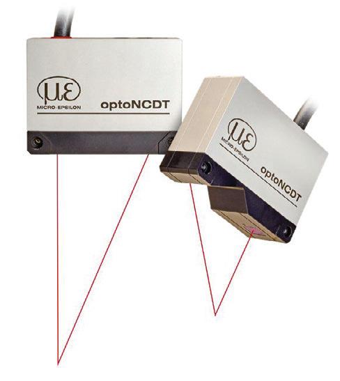
The optoNCDT 5500 laser displacement sensor from Micro Epsilon is a high-performance laser displacement sensor designed for precision measurement in dynamic applications. It is designed for high measurement speed and accuracy, making it a suitable choice for applications in demanding industrial environments.
The sensor is equipped with flexible connectivity options, including Ethernet, RS422, and analog outputs for integration into existing systems. Its web interface provides ready-made presets, making it easier to deploy and operate.
With a measuring rate of up to 75 kHz, the product is designed to provide reliable performance for fast-moving objects, and can achieve submicron accuracy and repeatability for applications requiring high precision. Intelligent algorithms enable stable measurement on challenging surfaces, including those with changing reflections and under ambient light up to 50,000 lux.
The IP67-rated aluminium housing provides durability in harsh environments, while the compact size and integrated controller simplify installation in tight spaces.
Bestech Australia Pty Ltd www.bestech.com.au
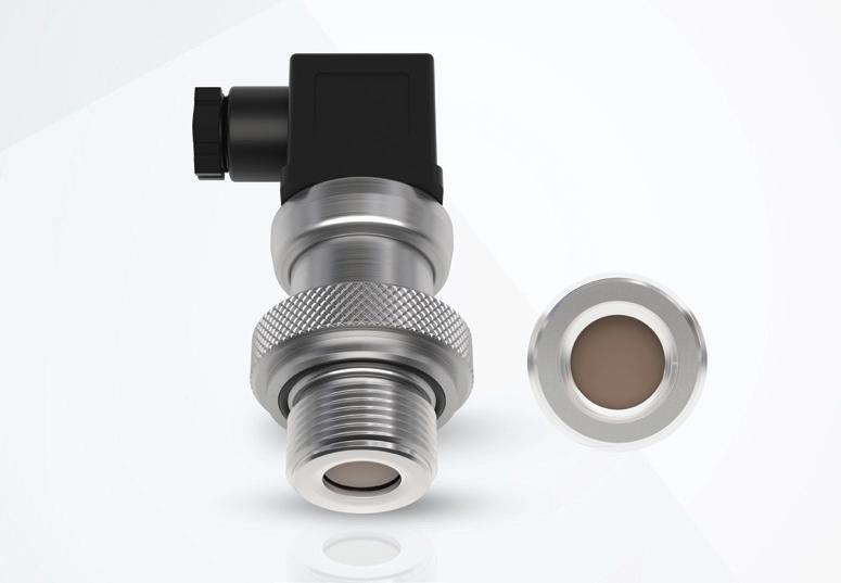
The Krohne OPTIBAR PC 1010 is an ultra-compact gauge pressure transmitter with a ceramic diaphragm, offering increased resistance to pressure surges, water hammer, abrasion and corrosion compared to metallic diaphragms. This makes the product suitable for water applications in which the jerky start-up of pumps can severely damage the stainless-steel measuring cell of conventional pressure transmitters.
For pump control in manholes prone to flooding, the pressure transmitter is available as an IP68 rated version designed to be waterproof. Due to its robust design, the pressure transmitter is suitable for long-term stable pressure and level measurement in many other industries as well as in factory automation. It is designed for simple applications with gases, vapours and liquids up to 40 bar and temperatures up to 125°C.
The dry capacitive measuring cell of the pressure transmitter works without filling oil, so leakage of filling oil into the process is not possible. The product is available with both a recessed and a frontflush ceramic diaphragm. The pressure transmitter is also available in an intrinsically safe version with ATEX/IECEx approval for use in Zone 0.
KROHNE Australia Pty Ltd www.krohne.com.au
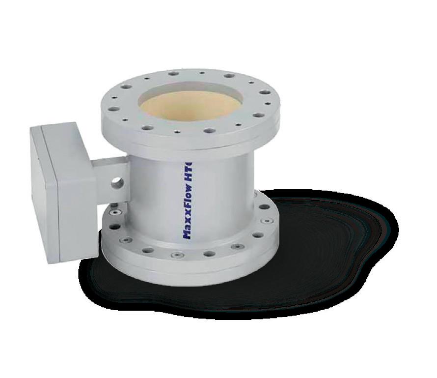
Electromagnetic flowmeter, designed to measure bulk material flows up to 300 t/h.
The meter has no mechanical parts in the flow, is 100% dustproof and erosion free because of ceramic inner pipe.
arbitrary mounting position (inclined/free fall) low headroom required easy to calibrate

Magnetic flow meters are often the best solution to measure flows of slurries, sludges and all manner of conductive liquids.
Amagnetic flow meter provides several advantages over many flow measurement alternatives, and it has certainly taken its place as one of the more common flow metering techniques, but a leading challenge for magnetic flow meters is the lack of an easy calibration method.
While experimenting with magnets and coils of wire in the early 1830s, Michael Faraday discovered he could create a voltage by moving a magnet through a conductive coil of wire (Figure 1).
Further experiments by Faraday and others would prove that the opposite was also true, so when a conductor was moved through a fixed magnet field, this would also generate a voltage.
Further testing showed the magnitude of voltage varied with the strength of the magnetic field, the speed of conductor or magnet movement, and the distance between the magnet and the conductor. Eventually Faraday’s law would be leveraged to create motors and generators, and it would spawn a wide range of related discoveries.
Perhaps not so obvious is the fact that Faraday’s experiments
also created a means to measure liquid flow in a pipe, for example a conductive liquid moving through a lined pipe (Figure 2). In this case the conductive liquid acts as the conductor moving through the fixed magnetic field crossing the pipe, creating a voltage across the electrodes. As the liquid velocity increases, the generated voltage rises. Note that the pipe must be lined with a nonconductive material to keep it from shorting the generated voltage signal to ground.
Magnetic flow meters have certain advantages over other flow meter technologies. Benefits of magnetic flow meters include:
• As full bore meters they create essentially no pressure drop.
• They can read flow in either direction.
• Turndown ratios of 100:1 or better are possible.
• They can operate in a wide range of pressures, temperatures and even a vacuum.
A wide variety of liner materials means that they are largely impervious to degradation or damage from most fluids, and the electrodes are typically very small — so even if an exotic material like platinum, nickel alloys or tantalum is required — they are relatively inexpensive, and they are an excellent choice for measuring flow of slurries and/or corrosive liquids. They are available in sizes up to 1.2 m or more.
• They are often more cost-effective than other flow measurement technologies, especially when full lifecycle costs are taken into account.
Magnetic flow meters do have limitations that are important to be aware of in certain applications, including:
• The fluid must be a conductive liquid, generally 5 µS/cm or higher.
• The meter cannot measure vapours or gases.
• Magnetic flow meters only work in pipes with full or nearly full flows.
• Magnetic flow meters can be installed in lined (non-conductive) pipes, though they usually require grounding rings for these applications.
• Magnetic flow meters are volumetric flow meters, and they cannot measure density or mass flow.
As mentioned above, magnetic flow meters are an excellent choice for slurry applications, including the very abrasive slurries found in mining applications. There are also meters for very demanding slurry applications, such as long fibres in pulp stock flows in pulp and paper applications, or sand and rocks in mining applications. These meters have an increased coil drive current and therefore a stronger magnetic field, providing increased induced voltage created when the conductive fluid passes through the magnetic field, which improves the signal-to-noise ratio. They can also provide users with the capability to change operating frequencies and signal processing methods, both useful because slurries tend to create a lot of process noise, and some frequencies work better than others.
Magnetic flow meters are also very common in water and wastewater applications and in corrosive service. They work well and generally have a long service life, except in very aggressive slurry applications, which can damage the liner. However, carefully selected
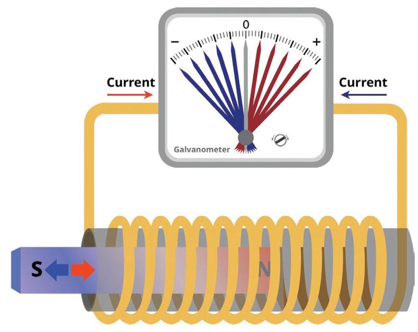
1: Faraday’s experiments in 1831 showed that moving a magnetic through a conductive coil of wire generated a voltage across the wires.
meter designs and liner materials can provide extended life even in these difficult environments.
When magnetic flow meters fail, the typical failure modes are somewhat limited. The meter may cease to operate correctly for any of these reasons:
• A less than full pipe will result in a low reading or no reading at all.
A pipe filled with a mix of gas and liquid can result in overreporting the liquid volume flow rate because the meter assumes the pipe is full of liquid.
• The electrodes can become coated with a non-conductive material, which blocks them from reading the voltage signal or reduces the voltage, resulting in a lower than actual reading.
• Conductive coatings can allow stray voltage signals to get picked up by the electrodes, causing false flow readings.
Coatings of any type can reduce the effective inside diameter of the pipe and lead to higher flow readings than actual values.
As a result, magnetic flow meters should be checked and have their performance verified on a routine basis. This is particularly true for mission-critical flow meters that must operate reliably and accurately to ensure smooth plant operations.
The pulsed nature of the magnetic field and resulting voltage creates a complicated signal that is not easily duplicated. As a result, calibration and testing of a magnetic flow meter is not straightforward. Typically, the only testing options include removing the meter from the line for flow testing or diverting the same flow through a check meter if the piping allows this configuration. Unfortunately, neither method is easily accomplished, so many magnetic flow meters get checked infrequently, if at all. Fortunately, modern magnetic flow meters offer smart meter verification that can verify that the magnetic flow meter is within calibration without needing to remove the meter from service.
Smart meter verification provides a review of the transmitter and sensor’s critical parameters, including coil inductance, coil resistance, electrode resistance, sensor voltage conversion and 4–20 mA output, as a means to document verification of calibration.

Baseline values for each of these measurements are recorded during initial commissioning and stored in the meter’s non-volatile memory. The meter can then either continuously check all the measurements as the meter operates, or tests can be manually initiated as required. Allowable deviations for each test are fully configurable, and individual tests can be disabled if necessary.
Meter signature capture
The first step for smart meter verification is to record baseline values such as coil resistance, coil inductance and electrode resistance. The baseline values provide a description of the magnetic behaviour of the transmitter and sensor. Based on Faraday’s law, the induced voltage measured on the electrodes is proportional to the magnetic field strength, therefore any changes in the magnetic field will result in a calibration shift of the sensor. Taking an initial sensor signature when the transmitter is installed establishes a baseline for future verification tests.
Ideally, this data should be captured during start-up and commissioning when the pipe is full of the typical process fluid and when there is no flow. This condition allows the most accurate measurement of the key sensor signature values.
It should be remembered however that electrode resistance cannot be measured if the pipe is empty, and measurements taken when process fluid is running through the meter will inject some signal noise.
Sensor health verification includes the resistance test data from the coil inductance and resistance test and data from an electrode resistance test. These tests are designed to check the health of the coil and electrode circuits.
Sensor calibration verification is done with the coil inductance and resistance test. Coil inductance is the key characteristic of the coils because it determines the magnetic field strength.
Coil inductance and resistance
A magnetic flow meter is dependent upon a consistent magnetic field to generate an accurate flow signal. This magnetic field is created by a pair of coils built into the top and bottom of the meter, which are energised with pulsed DC current. Any change in the performance of these coils will impact the flow reading.
Electrode resistance
If the pipe is full, the resistance across the electrodes will be a function of the process fluid conductivity and should fall within a consistent range. The electrode health check looks for significant deviations in the resistance between the electrodes. Very low resistance suggests the electrodes are shorted to ground, likely due to a damaged liner. Very high resistance suggests an empty
pipe, failed electrode, or possibly very heavy electrode coating. An advanced diagnostic check, discussed below, provides customisable alerts for electrode coating detection.
Transmitter and analog output check
A smart verification diagnostic simulates a voltage into the transmitter that mimics an actual flow velocity reading. When the simulated voltage is applied, the verification check compares the output of the transmitter and the analog output to confirm they match the expected values. This diagnostic effectively tests the ability of the transmitter to read a sensor voltage and accurately convert it to a 4–20 mA output scaled to flow.
Test initiation
Typically, any or all of the tests and checks listed above can be manually initiated. Additionally, the meter can be set up to continuously run the tests while it is in operation, and to generate an alert should a test fall out of specification, or to generate a report as required.
Magnetic flow meter diagnostic options include basic features such as empty pipe detection, reverse flow detection and grounding and wiring alarm, and additional diagnostics are offered as an option. Process diagnostics detect and warn of abnormal situations throughout the life of the meter related to:
• High process noise: Detects if there is a process condition causing an unstable or noisy reading that is not an actual flow variation, a common cause being slurry flow, such as pulp stock or mining slurries.
• Coated electrode detection: Provides a means of monitoring insulating coating build-up on the measurement electrodes, since build-up over time can lead to a compromised flow measurement.
Magnetic flow meters offer cost-effective and reliable flow measurement for a broad range of applications, but they have historically been difficult to calibrate without process interruption. That problem has been solved in modern magnetic flow meters with smart meter verification diagnostics. With this advancement, meter functionality from the sensor through the analog output can be fully tested without removing the meter from service. While testing with a full pipe and no flow is preferred, the meter can be tested to a very high degree of certainty even with flow moving through the pipe, providing testing options for mission-critical applications that cannot be interrupted.
ECD’s OIW80 oil-in-water analyser is designed to help detect oily water leaks quickly to help ensure effluent requirements are met to avoid shutdowns, fines and clean-ups.
The analyser’s fluorescence sensing technology identifies petrochemical leaks or spills and monitors treated effluent to help prevent drinking water pollution, protect ecosystems, reduce emergency shutdowns, product batch fouling, unplanned maintenance, regulatory corrective actions and fines.
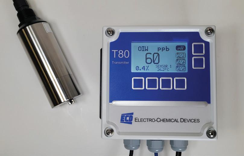
The OIW80 measures oil over a wide range of 0–15 ppm (mg/L) and can be factory preconfigured to measure oil in multiple ranges or easily set in the field. The analyser’s sensor operates over a broad temperature range from 5 to 45°C, quickly detecting leaks and alerting plant technicians.
Suitable for dirty plant environments, the analyser features a rugged sensor with a built-in wiper cleaning system that removes bio-solids and films that might cloud the sensor window’s visibility, reducing the need for unplanned manual checks by technicians and scheduled maintenance cleanings.
Corrosion-resistant stainless steel (standard) or optional titanium construction meets the IP68 water ingress standard. The sensor communicates with ECD’s T80 Universal Transmitter upon oil detection or ECD’s LQ800 Controller or directly with a control system (PLC) via the sensor’s serial communications.
AMS Instrumentation & Calibration Pty Ltd www.ams-ic.com.au
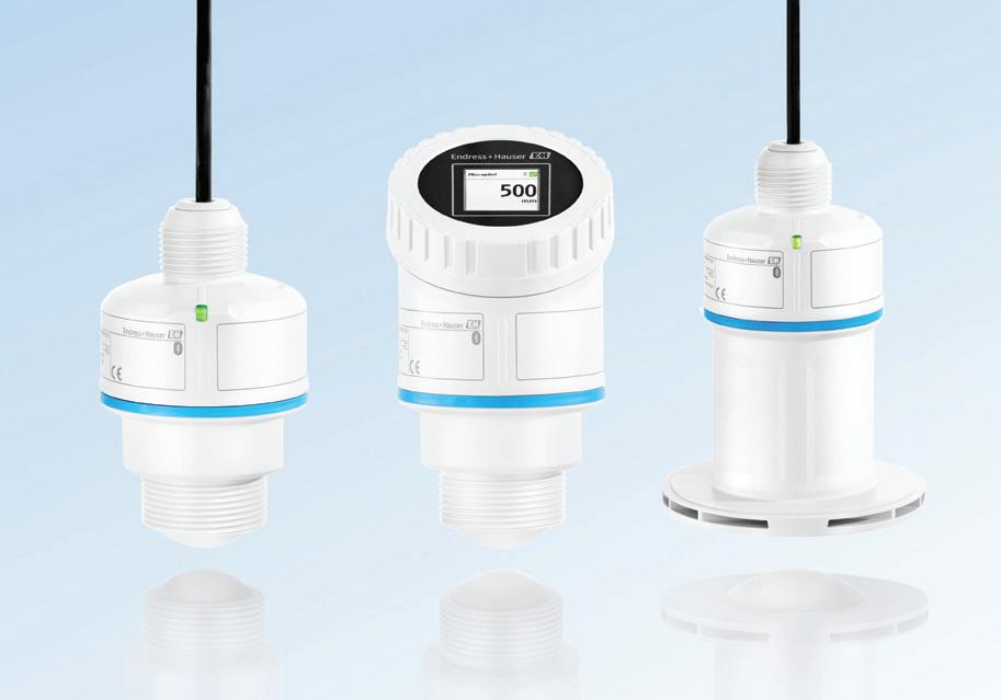
The Endress+Hauser Micropilot FMR10B, FMR20B and FMR30B radar level sensors are designed for continuous level measurement with 80 GHz radar technology for all main applications in the water and wastewater industry, as well as in basic applications in the mining, minerals and metals industry.
Designed for fast commissioning and easy operation, setup sequences with help texts and illustrations guide users through the process.
In addition, the devices can be operated via remote access through a smartphone or tablet or directly on the device by using the colour touch display. An integrated ‘It’s me’ function allows any measuring device to be identified in seconds, which is helpful when several measuring devices are being used in a system. When connecting to the device via Bluetooth, a flashing display (Micropilot FMR30B) or flashing LED (Micropilot FMR10B and FMR20B) gives a clear device identification. Those LEDs and the display also provide precise information on the status of each device during operation. In case of a malfunction, the LED colour changes, and the display also indicates the status. The Micropilot FMR30B, with its colour touch display, provides additional on-device control without opening the lid. With Heartbeat Verification, the functionality of the measuring devices can be evaluated at any time. Endress+Hauser’s Radar Accuracy Index (RAI), in combination with Heartbeat Technology verification, enables the traceable verification of the accuracy of the radar with a procedure certified and documented in accordance with ISO 9001.
Endress+Hauser Australia Pty Ltd www.au.endress.com
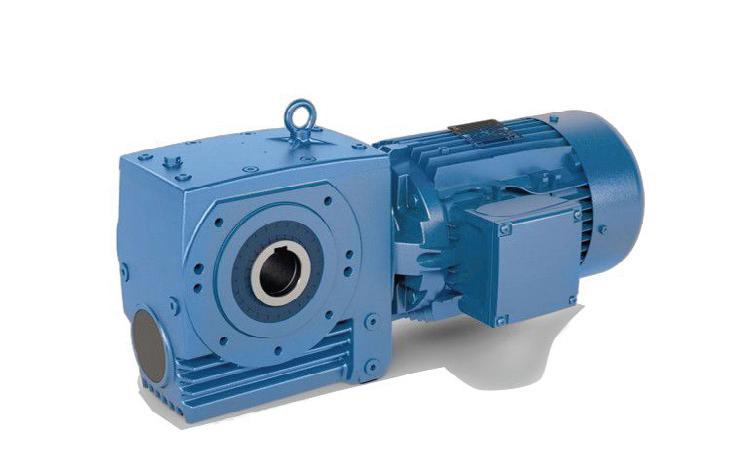
NORD Drivesystems has increased the maximum torque of its UNICASE worm gear units, achieving an increase in performance of 10–15% without changing the gear units’ outer dimensions. Higher performance can now be achieved without the need for adjusting existing configurations.
As the housing sizes remain unchanged, the worm gear units will still be available as a drop-in solution for maintenance works or repairs. To save costs and installation space, smaller sizes can be selected according to the application, resulting in more constructive freedom in machine and system design.
The dimensions have not changed, but in order to implement higher power ranges, NORD incorporated new worm shafts with larger bearing seats, as well as an additional reinforcement of the worm wheel itself. The current UNICASE worm gear unit series offers a power range from 0.12–15 kW, and torques between 90 and 3000 Nm. NORD says other advantages include smooth and quiet running, high overload capacity and robust design.
The UNICASE worm gear units in cast iron housings are available in application-specific versions: as hollow and solid shaft gear units, and for shaft, flange or foot mounting. The company’s electric motors can be added as an integrated solution. Motor mounting via an IEC/NEMA adapter is also possible.
NORD Drivesystems (Aust) Pty Ltd www.nord.com

ADLINK Technology has announced the launch of its SP2-MTL Series, a next-generation open-frame panel PC engineered to meet the growing demand for edge AI, in real-time, missioncritical and data-driven industrial environments.
Powered by the Intel Core Ultra H Series (Meteor Lake) processors, the SP2-MTL is designed to provide efficient, high-performance AI inference at the edge. To support more advanced workloads, the system offers flexible GPU expansion via NVIDIA MXM Type-A or PCI Express graphics cards, enabling scalable acceleration for applications such as machine vision, automated optical inspection (AOI), automated dispensing systems or pharmacy carousels.
Its open-frame architecture allows for integration into custom enclosures, equipment and public-facing terminals, significantly reducing design effort and time-to-market.
Full customisation support is available, including optical enhancements, mechanical design and function expansions. Certified for industrial safety, EMC compliance and shock and vibration resistance, it is purpose-built for harsh environments and mission-critical deployments.
ADLINK Technology Inc www.adlinktech.com

Mitsubishi Electric has announced its GOT3000 HMI, which is designed to support the manufacturing sector’s accelerating digital transformation with capabilities that enhance connectivity, usability and system integration.
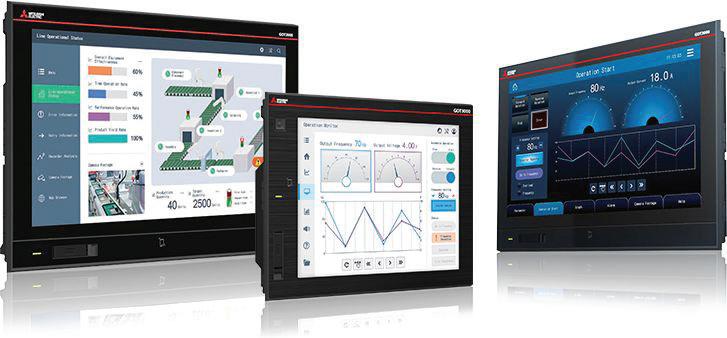
The product is designed to act not only as a machine interface but as a secure gateway between factory equipment and higher-level IT systems. By supporting international standards for industrial communication, such as OPC UA Client1 and OPC-UA Server and Cloud, it is designed to enable integration with higher-level information systems and a wide range of factory automation devices.
The device also includes a built-in web browser, allowing users to configure and monitor equipment without a PC, and supports communication features such as NFC contactless tag reading and USB-C connectivity. It also offers USB camera connectivity and built-in HDMI output, and is designed to support network camera connectivity in the future, further expanding its capabilities for real-time monitoring and system integration.
Secure remote access is enabled through encrypted communication, data encryption and built-in VPN capabilities, making it easier to manage multiple devices from a central location via the cloud.
Compatibility with Mitsubishi Electric’s MX Controller allows for system integration, streamlining communication between HMI and controller and reducing engineering overhead. This support for a wide variety of connectivity standards, including the CC-Link IE TSN industrial network, and legacy systems allows the GOT3000 to fit into a broad range of production environments.
A newly developed high-definition display that is capable of rendering up to 16 million colours is paired with a capacitive multi-touch touchscreen.
Mitsubishi Electric Australia www.mitsubishielectric.com.au

Metromatics has announced the local availability of the Acromag NT2710 stepper motor controller module, the latest addition to Acromag’s BusWorks NT Series of Ethernet I/O solutions.
The NT2710 provides six pulse train/logic outputs, six encoder inputs and four general-purpose digital I/O channels for stepper motor driver control. A wide range of commands allow for precise management of position, speed and direction, while linear, triangular, trapezoidal and S-Curve acceleration/deceleration profiling helps provide smoother movement and reduced mechanical stress in demanding applications.
Supporting Modbus TCP/IP, EtherNet/IP, and Profinet protocols, the NT2710 is designed to integrate seamlessly with PCs, PLCs and PACs. For IIoT environments, it also includes an OPC UA server, MQTT client and RESTful API, making it suitable for smart manufacturing, predictive maintenance, and remote monitoring systems.
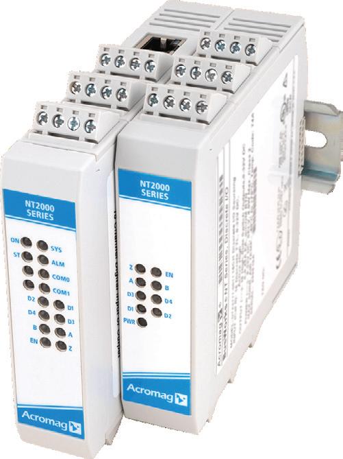
Designed for scalability, NTE Ethernet models offer dual RJ45 ports for communication plus stepper I/O channels. Users can expand the system by linking up to three NTX modules on the DIN rail bus, achieving control of up to 64 channels per Ethernet IP address. Other NT Series modules can also be combined to monitor or control voltage, current, temperature and discrete signals, enabling a fully integrated automation solution.
Typical applications for the NT2710 include machining, packaging, dispensing, positioning and printing systems, along with any industrial process requiring accurate motion control.
Metromatics Pty Ltd www.metromatics.com.au

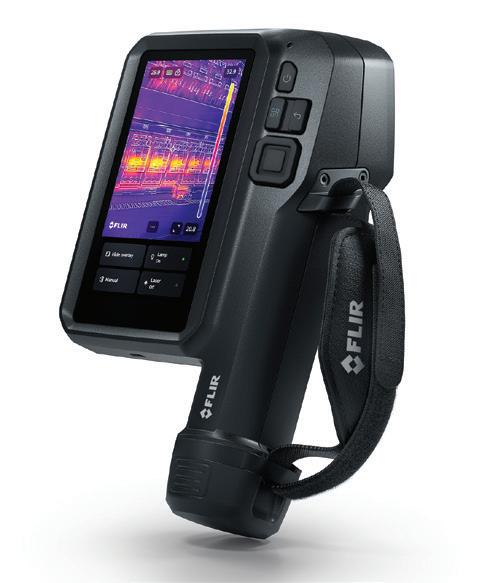
Flir has introduced the iXX-Series of app-enabled thermal cameras. Built on the company’s ACE platform, the iXX combines apps with a thermography inspection tool in order to enable scalable and connected condition monitoring. Direct integration with Flir’s Assetlink browser-based software automatically connects Flir radiometric images to an asset hierarchy structure to help speed up workflows.
According to Flir, around 60% of maintenance teams report a shortage of skilled thermographers. To help overcome this issue, intuitive, app-guided workflows on the iXX-Series aim to enable maintenance workers of any skill level to undertake efficient and secure inspections.
The camera comes with everything needed to get started, providing an onboarding app to help with successful adoption. The result is a shallow learning curve for less experienced users looking to perform expert-level inspections and accurately assess asset condition.
The product comes loaded with Assetlink browser-based software, which allows users to plan inspections, connect thermal images to asset data, and produce inspection reports with the goal of simplifying workflows, improving asset health and reducing reporting time. Furthermore, trend visualisation provides insight on asset condition not possible with a single snapshot, while dashboard data visualisation simplifies communication and improves operator understanding of condition monitoring programs.
Direct cloud integration takes place via Wi-Fi or LTE (certain models only) for immediate uploading, organisation and sharing of data, as well as seamless reporting and analysis. Operators can send and receive messages, emails and even video calls directly from the device to stay connected with their team.
Teledyne FLIR www.flir.com.au
INTERFACE WIRELESS LOAD PINS ARE DESIGNED TO DIRECTLY REPLACE EXISTING LOAD-BEARING PINS IN A CRANE’S HEADER BLOCK, PROVIDING A SIGNAL PROPORTIONAL TO THE MEASURED LOAD.
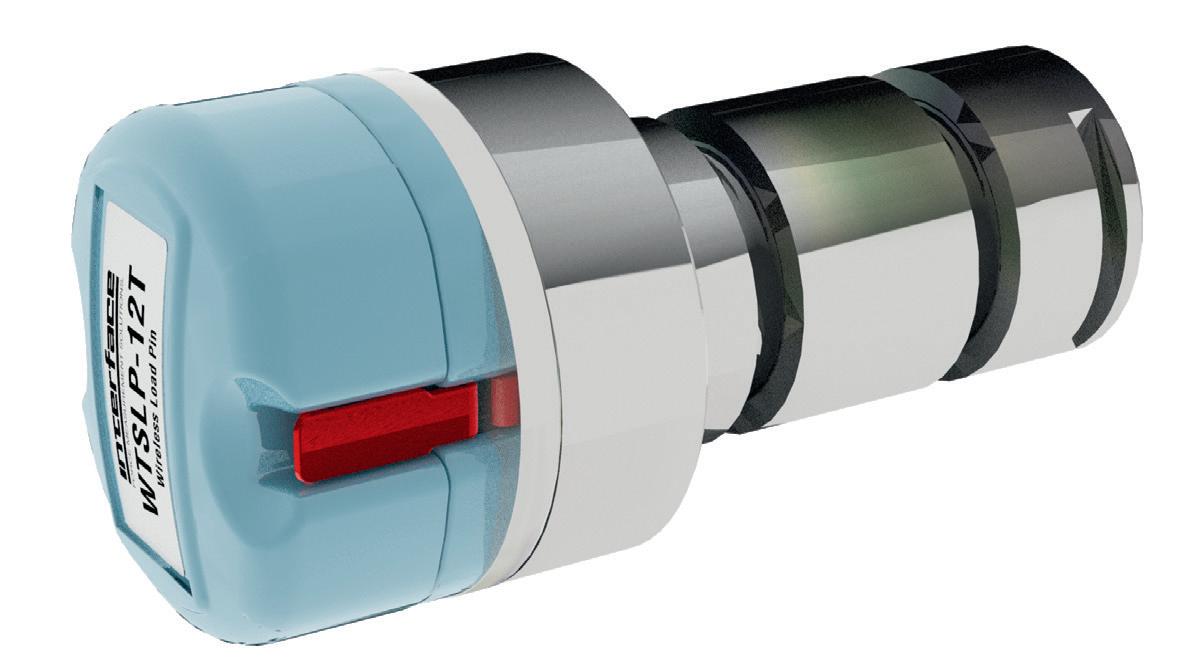
Gantry cranes are essential for various mobile and lifting applications in industrial and construction environments. A reliable weighing system is crucial to ensure the crane can safely handle heavy containers or loads, preventing failures and accidents.
A load pin, which often replaces a standard clevis or pivot pin, is a strain gauge sensor that measures the force applied across the device. The strain gauges are installed within a small bore through the centre of the pin. Interface load pins have been used in a wide variety of projects across many industries.
Load pins are a simple, but highly powerful sensor that provides data collection for accurate and frequent measurement. The load pin can replace a bolt, clevis, sheave, and an equaliser pin, as well as other load-bearing components to measure tensile and compression forces.
Machined from high tensile stainless steel, Interface load pins are suitable for exposed situations including seawater. Interface off er standard sizes of load pins between 500 kg to 1500 MT, and they are custom manufactured to meet specific dimensional requirements for each application.
The most commonly referenced applications for load pins are for overhead equipment like cranes and lifts. Through ingenuity of engineers and our customers, load pins are rapidly expanding in popularity for infrastructure, aerospace, maritime, agriculture, and industrial use cases. The load pins of today are used to test and measure force, load, and weight in a much larger variety of applications. They are also growing in demands due to their wireless capabilities for both short and long distances. This includes uses not only for cranes and lifting devices, as well as construction equipment, industrial machines, nautical craft and equipment, aerospace structural environments, and civil engineering applications.
Interface offers a range of sensor options for crane weighing and overload protection systems. These systems assist operators by providing real-time total weight data, preventing overload situations. Interface engineering experts has decades of experience delivering
measurement solutions for these systems, which have been installed in all types of hoists and cranes, including overhead travelling cranes, construction cranes, infrastructure project cranes, shipyard and port cranes, as well as marine and offshore cranes.
Interface Wireless Load Pins are designed to directly replace existing load-bearing pins in a crane’s header block, providing a signal proportional to the measured load without requiring any modifications to the crane. This allows the crane weighing and overload system to alert the operator of potential lifting hazards and assist with safe load management. Pre-set audible and visual alarms can also be integrated, along with triggers to shut down the crane if a lift exceeds the safe load limit.
Interface has a great deal of experience supplying ruggedised and standard use load pins for testing. The load pins are in high demand in the infrastructure industry not only due to their accuracy and reliability, but also due to the fact that Interface offer a myriad of communication channels through both wired and wireless solutions. As requirements are made to repair and rebuild public infrastructure resilience, equity, and safety for all users are key criteria in design and build stages. This is where Interface load pins are key to the solution, for durability, accuracy, quality, and ease of use.
For demanding environments such as oil rigs and FPSOs, Interface can supply ATEX- and IECEx-certified measurement sensors with both explosion-proof (Ex d) and intrinsically safe (Ex i) approvals. Interface also offer below-hook solutions for situations where permanent installation is not required or where using a load measuring pin isn’t feasible.

MIT engineers have designed a versatile interface that allows users to teach robots new skills in more intuitive ways. Currently, teaching a robot new skills usually requires coding expertise, but the experimental interface designed by the MIT researchers allows a robot to learn by demonstration.
The researchers’ more natural training strategy enables a person to lead a robot through a task in one of three ways: via remote control, such as operating a joystick to remotely manoeuvre a robot; by physically moving the robot through the motions; or by performing the task themselves while the robot watches and mimics.
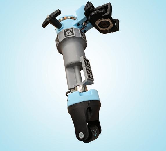
Learning-by-doing robots usually train in just one of these three demonstration approaches, but the MIT engineers have now developed a three-in-one training interface that allows a robot to learn a task through any of the three training methods. The interface is in the form of a handheld, sensor-equipped tool known as the ‘versatile demonstration interface’ (VDI), which can attach to many common collaborative robotic arms.
The researchers say the new interface offers increased training flexibility that could expand the type of users and ‘teachers’ who interact with robots. It may also enable robots to learn a wider set of skills.
“We are trying to create highly intelligent and skilled teammates that can effectively work with humans to get complex work done,” said Mike Hagenow, a postdoc at MIT in the Department of Aeronautics and Astronautics.
“We believe flexible demonstration tools can help far beyond the manufacturing floor, in other domains where we hope to see increased robot adoption, such as home or caregiving settings.”
The team’s new work builds on an emerging strategy in robot learning called ‘learning from demonstration’, in which training methods fall generally into the three main categories of teleoperation, kinaesthetic training and natural teaching.
“If we could bring together these three different ways someone might want to interact with a robot, it may bring benefits for different tasks and different people,” Hagenow said.
When the interface is attached to a robot, the entire robot can be controlled remotely,

and the interface’s camera records the robot’s movements, which the robot can use as training data to learn the task on its own. Similarly, a person can physically move the robot through a task, with the interface attached. The VDI can also be detached and physically held by a person to perform the desired task. The camera records the VDI’s motions, which the robot can also use to mimic the task when the VBI is reattached.
To test the attachment’s usability, the researchers set up an experiment where they asked volunteers at a manufacturing innovation centre to use the robot and all three of the interface’s training methods to complete two common manufacturing tasks: press-fitting and moulding. In press-fitting, the user trained the robot to press and fit pegs into holes, similar to many fastening tasks. For moulding, a volunteer trained the robot to push and roll a rubbery, dough-like substance evenly around the surface of a centre rod, similar to some thermo-moulding tasks. For each of the two tasks, the volunteers were asked to use each of the three training methods.
The researchers found the volunteers generally preferred the natural method over teleoperation and kinaesthetic training. The users, who were all experts in manufacturing, did offer scenarios in which each method might have advantages over the others. Teleoperation, for instance, may be preferable in training a
robot to handle hazardous or toxic substances. Kinaesthetic training could help workers adjust the positioning of a robot that is tasked with moving heavy packages. And natural teaching could be beneficial in demonstrating tasks that involve delicate and precise manoeuvres.
“We imagine using our demonstration interface in flexible manufacturing environments where one robot might assist across a range of tasks that benefit from specific types of demonstrations,” said Hagenow, who plans to refine the attachment’s design based on user feedback and will use the new design to test robot learning. “We view this study as demonstrating how greater flexibility in collaborative robots can be achieved through interfaces that expand the ways that end-users interact with robots during teaching.”

Theo Lai, Product Manager, Moxa
The goal of industrial cybersecurity is to enhance existing architectures with layered, pragmatic security measures.
Industrial networks are no longer isolated islands. The convergence of information technology (IT) and operational technology (OT) systems, driven by digital transformation, remote operations and data-driven decisionmaking, has fundamentally reshaped the cybersecurity landscape.
Historically, OT environments relied on physical isolation (air gapping) and perimeter defences to safeguard critical systems. However, the rise of ransomware, supply chain attacks and advanced persistent threats has exposed the limitations of this approach.
To address these challenges, cybersecurity strategies have evolved from perimeter-
based defences to a layered, identity-aware approach. Principles such as defence in depth and zero trust, while originating in IT, are now essential considerations for securing OT environments. Rather than assuming implicit trust based on network location, modern industrial networks require continuous verification of devices, users and traffic behaviours, ensuring that every interaction is explicitly authorised and monitored.
The IEC 62443 standard provides a comprehensive framework for securing industrial automation and control systems. It defines concepts such as zones, conduits and defence-in-depth strategies that guide the design of secure network architectures.
In this context, network architecture design becomes the foundation for practical security implementation, translating these principles into deployable strategies that align with operational realities.
Industrial network architectures have evolved in response to the breakdown of the traditional air gap model. Historically, OT environments relied on physical isolation from IT systems to maintain security. However, the need for digital transformation, operational efficiency needs and remote access has dissolved this separation. IT/OT convergence is no longer optional, driving the need for structured approaches to manage interconnectivity and security.
This evolution has led to three common architecture types: complete separation (Type 1); shared IT/OT platforms (Type 2); and full integration (Type 3). Each type reflects a different balance between isolation, operational integration and security strategy.
The evolution of architectures from Type 1 to Type 3 reflects a broader transformation in industrial network design. Initially, strict physical separation ensured security through isolation, but this limited scalability and operational flexibility. The emergence of shared IT/OT platforms (Type 2) addressed these limitations by enabling controlled service interactions through DMZs and segmented conduits.
As the digital transformation trend accelerates, full integration (Type 3) architectures have become prevalent, driven by the need for unified infrastructure and resource optimisation. This shift requires replacing physical boundaries with logical segmentation, dynamic access control and continuous monitoring to manage the expanded attack surface.
Type 1: complete separation
In traditional OT environments, IT and OT networks are designed to be independent and isolated systems. This separation is not a newly introduced security measure, but an inherent characteristic of how industrial control systems have been deployed
historically — prioritising reliability, availability and operational stability over connectivity.
However, with the acceleration of digital transformation, even isolated OT environments face new cybersecurity challenges. Threats now enter through alternative vectors such as portable media (USB drives), third-party maintenance connections and supply chain vulnerabilities. This has made it essential to reinforce the existing separation with additional security controls to ensure that isolation remains effective in a more connected world.
Type 1 architectures maintain the principle of physical or logical separation between IT and OT, with independent infrastructures for each domain. When crossdomain data exchange is required — such as sending telemetry data from OT to IT— controlled conduits are established using DPI firewalls and data diodes to enforce oneway, policy-governed communication.
Within the OT domain itself, internal segmentation is implemented using access control lists (ACLs) in Layer 2 and Layer 3 switches, limiting east–west traffic between devices or functional zones and reducing the risk of lateral movement in the event of an internal compromise. While Type 1 environments rarely adopt dynamic, identitybased access controls, basic measures such as disabling unused ports and hardening
critical devices remain essential. These controls uphold the principle of minimising the attack surface to ensure that the OT network remains resilient despite evolving threat landscapes.
As industrial operations become increasingly reliant on centralised management and streamlined maintenance, IT-hosted services — such as Active Directory, patch servers and asset management systems — are gradually being introduced into OT environments. This shared service model improves operational efficiency but also introduces new security challenges, particularly at the intersection of IT and OT domains.
To mitigate these risks, Type 2 architectures implement a layered segmentation strategy:
• A demilitarised zone (DMZ) is established to serve as a buffer, hosting intermediary services that mediate IT/OT interactions and preventing direct access from IT systems to OT assets.
• At the IT/OT boundary, DPI firewalls enforce cross-domain traffic policies, performing protocol-aware inspection and filtering unauthorised access attempts.
• Within the OT domain, internal segmentation is refined through ACLs and identity-based access controls.
Technologies such as network access control (NAC) are commonly used to
Micro-segmentation, dynamic access, behavioural analytics Boundary
with virtual segmentation at aggregation points
Internal segmentation
(L2/L3 switches)
+ NAC (identitybased control)
+ VLAN (basic segmentation) Dynamic control None (static network design) NAC dynamically adjusts access permissions
Visibility Requirement Necessary, but low frequency of change
Micro-segmentation and dynamic policies (behaviour/identity-based)
High visibility and anomaly detection as required core capabilities
PRINCIPLES SUCH AS DEFENCE IN DEPTH AND ZERO TRUST, WHILE ORIGINATING IN IT, ARE NOW ESSENTIAL CONSIDERATIONS FOR SECURING OT ENVIRONMENTS.

dynamically verify device identities, manage access scopes, and adapt policies based on compliance and operational context. This ensures that shared services remain functionally integrated while minimising lateral movement risks and maintaining segmentation integrity.
Rather than relying on a single perimeter, Type 2 architectures employ multiple layers of defence, ensuring that operational gains from IT/OT integration do not compromise the integrity of critical OT systems.
Type 3: full integration
With growing demands for centralised management, real-time data analysis and infrastructure efficiency, many organisations are adopting fully converged networks where IT and OT systems coexist on shared Layer 2/3 infrastructures.
In this architecture, physical segregation is replaced by logical segmentation, relying on VLANs, ACLs and dynamic policy enforcement to maintain operational integrity.
While convergence simplifies deployment and reduces infrastructure complexity, it significantly increases security challenges. The absence of clear network boundaries amplifies the risk of lateral movement, identity misuse and visibility gaps.
To address these challenges, Type 3 architectures deploy a combination of multilayered logical segmentation and
adaptive access control mechanisms. DPI firewalls continue to secure aggregation points, managing inter-domain traffic flows, but the primary defence shifts towards micro-segmentation, which enables finegrained isolation of devices, workloads and user sessions within a converged environment. Within this framework, NAC systems authenticate devices, assess compliance, and dynamically enforc security breach.
This comprehensive approach allows Type 3 architectures to maintain a robust security posture, aligning operational flexibility with cybersecurity best practices.
Network visibility and anomaly detection
Comprehensive visibility is essential for maintaining network security. Passive asset discovery, flow analysis and behaviour monitoring establish operational baselines. Anomaly detection identifies deviations indicative of compromise or policy violations, enabling swift response and containment.
Beyond the network: people, process and procedures
Technical controls are only part of the security equation. Effective cybersecurity also requires well-defined processes and trained personnel. This includes incident response planning, change management with security
validations, and continuous training for operators and engineers.
Defence in depth: a holistic security perspective
True resilience comes from a multilayered defence-in-depth strategy. This includes asset hardening, identity and access management, anomaly detection, and robust incident response processes.
Defence in depth ensures that even if one layer fails, others can mitigate the impact. Aligned with IEC 62443 principles, this approach is crucial for managing risks in increasingly interconnected IT/OT environments.
The goal of industrial cybersecurity is to enhance existing architectures with layered, pragmatic security measures. Type 1 focuses on enforced separation, Type 2 balances shared services with segmented control, and Type 3 demands pervasive micro-segmentation and dynamic policy enforcement.
System integrators must align security strategies with the state of their current networks, and apply IEC 62443 principles in a risk-informed manner to build resilient and secure industrial networks.
An increasing amount of electronic waste is not being properly disposed of, instead being discarded together with other waste. If the batteries in these products are damaged, they can cause fires at sorting plants. As part of the DangerSort project, researchers at the Fraunhofer Institute for Integrated Circuits IIS are using a sensor-based sorting system to remove hazardous items and make recycling plants safer.
More than 10,000 fires occur annually in German waste sorting plants, and around 80% of these fires are caused by lithium-ion batteries. Common in smartphones, electric toothbrushes and even singing greeting cards, these batteries are often disposed of together with packaging waste. They can be damaged and catch fire, particularly during the recycling process in sorting plants. The damage caused by this is estimated at around one billion euros a year.
The DangerSort project aims to reduce the risk of fire in sorting plants.
“We are developing a sensor-based sorting system that uses X-ray technology and artificial intelligence to detect hazardous lithium-ion batteries and separate them from the rest of the
waste stream at an early stage,” said Johannes Leisner, Head of the Sorting and Laboratory Systems group at the Development Center X-ray Technology at Fraunhofer IIS. “So far, there have been no preventive measures against fires caused by batteries — only solutions to combat them, such as improved fire extinguishing systems. The sensor-based technology could also make it easier to recycle batteries, closing their product life cycle.”
A prototype system set up at Fraunhofer IIS demonstrates the potential of the idea. A highspeed conveyor belt in the X-ray sorting system, which moves at speeds up to 3 m/s, transports the waste stream. An X-ray source above the conveyor belt operates like an airport luggage scanner and screens the material stream. This technology can also identify batteries installed in appliances or concealed by other waste. An X-ray detector mounted below the conveyor belt takes images at the speed of the conveyor, resulting in a continuous series of radiographs. The series of images is then evaluated.
“To do this, we are applying an AI system that is designed for particularly rapid image
processing and is normally used in autonomous driving applications,” Leisner said. “We have adapted and retrained it so that it can also analyse radiographs to specifically detect electrical appliances that contain lithium-ion batteries.”
Sorting is initiated based on the data collected. This information enables the control of compressed air valves that separate hazardous electrical appliances from the waste stream. Air nozzles measuring around 5 mm remove them from the belt and convey them into a separate chamber. The right timing between evaluating the radiograph and starting the nozzles is crucial for this process.
“It is difficult to detect and isolate different battery sizes during the separation process, as these can range from 10 kg e-bike batteries to button batteries,” Leisner said.
At the time of writing, the sorting system is still undergoing tests at Fraunhofer IIS and the plant is scheduled to be delivered to waste disposal company LOBBE for the first practical tests.
Fraunhofer Institute for Integrated Circuits IIS www.iis.fraunhofer.de/en.html

Ella Averill-Russell, IICA Sydney Branch Manager
For decades, water utilities have relied on fixed-interval preventive maintenance to keep pumps, valves and treatment equipment in service. Scheduled inspections and replacements helped avoid catastrophic breakdowns, but they also created inefficiencies: parts were often replaced too early, or failures still slipped through between intervals.
Predictive and condition-based maintenance (PdM/CBM) is now reshaping how utilities manage assets. By harnessing data from sensors, IoT connectivity and edge computing, operators can detect early warning signs of failure and act only when necessary. The pay-off is higher reliability, lower lifecycle costs and more resilient service delivery.
Condition-based maintenance starts with smarter measurement. Vibration sensors can reveal bearing wear or pump misalignment, acoustic devices detect leaks in pipelines, and pressure and flow sensors highlight hydraulic inefficiencies. Chemical probes monitor water quality and corrosion risks. Traditionally, these data streams flowed into SCADA systems, but transmitting raw, high-frequency information is expensive and unreliable, especially in remote pumping stations.
This is where edge AI proves critical. Compact processors installed directly at the asset can filter noise, run anomaly detection and trigger alerts in real time, even if communications are interrupted. By pairing IoT sensors with local intelligence, utilities can detect deviations within minutes instead of waiting for monthly inspections or operator observations.
Predictive analytics goes further by using machine learning to estimate the remaining useful life of assets. Rather than simply flagging a fault, models can forecast how long a component is likely to last. Maintenance can then be scheduled during low-demand periods, coordinated with other tasks, and completed without costly emergency callouts. Pump stations, pipeline networks and treatment plants are already benefiting: vibration monitoring prevents catastrophic bearing failures; acoustic and pressure data localise leaks and reduce non-revenue water; predictive dosing models optimise chemical use and extend membrane life.
As one industry leader observed, “For an industry under pressure from climate stress and aging infrastructure, predictive maintenance is not just an upgrade — it is a step change.”
Modern asset intelligence platforms are helping make this a reality. These systems integrate diverse sensor inputs into a single environment, apply predictive algorithms and prioritise maintenance according to risk. Just as importantly, they link analysis to field operations, enabling technicians to feed observations back into the system via mobile devices and create a continuous loop of learning. The result is a shift from spreadsheet-based planning to dynamic, data-driven decision-making.
The benefits are significant: extended asset life, reduced downtime and smarter capital planning. Some utilities report halving unplanned failures once predictive strategies are in place.
Challenges remain. Data quality must be assured, integration with legacy assets can be complex, and the workforce needs to adapt to AIdriven insights. Yet the momentum is clear. As sensors become cheaper and edge AI more capable, predictive maintenance will become the norm. For water utilities, it represents not just new technology but a cultural shift, from fixing assets when they fail to managing them proactively for resilience, efficiency and long-term value.
October
International Mining and Resources Conference + Expo (IMARC) 21–23 October 2025
ICC Sydney imarcglobal.com
Workplace Health & Safety Show 22–23 October 2025
The Dome, Sydney Olympic Park whsshow.com.au/whats-on-sydney
IICA Technology Expo Townsville 29 October 2025
The Ville Resort-Casino iica.org.au/Web/Web/Events/Event_Display. aspx?EventKey=IICATVQLD
All Energy Australia 29–30 October 2025
Melbourne Convention and Exhibition Centre www.all-energy.com.au/en-gb.html
Endress+Hauser APAC Summit 30 October 2025
Crown Perth
endress.azavista.com/w/event/67d75646d26e4f338a15ad09
November
IICA TÜV Functional Safety Engineer SIS Training — Brisbane 4–7 November 2025
The Sebel, Brisbane City iica.org.au/iCore/Events/Event_display. aspx?EventKey=BNESEPTTUV
IICA Technology Expo Launceston 11 November 2025
Country Club Tasmania, Prospect Vale iica.org.au/Web/Web/Events/Event_Display. aspx?EventKey=IICALAUN25
IICA Technology Expo Hobart 13 November 2025
Wrest Point Hotel iica.org.au/Web/Web/Events/Event_Display. aspx?EventKey=IICAHOBART
IICA Technology Expo Adelaide 26 November 2025
Ridley Centre, Adelaide Showgrounds iica.org.au/Web/Web/Events/Event_Display. aspx?EventKey=IICAADLD25
Modern manufacturing faces relentless pressure to improve efficiency, reduce downtime, and maximise productivity. Amid labour shortages, supply chain disruptions, and rising operational costs, manufacturers are turning to smarter maintenance strategies — particularly condition monitoring — to stay competitive. When reading a recent article by my colleague Tom Knauer, ‘From WWII Bombers to Smart Factories: The Data-Driven Evolution of Maintenance’1, I was a little surprised to learn that , the roots of this approach trace back to World War II, when the Royal Air Force (RAF) pioneered data-driven maintenance to keep bombers flying during the Battle of the Atlantic.
In 1942, the RAF’s Coastal Command faced an urgent challenge: German U-boats were sinking Allied ships faster than they could be protected. Long-range bombers were a key defence, but most were tied up in strategic bombing campaigns. To solve this, the RAF formed an Operational Research Section, to analyse both combat tactics and aircraft availability.
Their findings were perhaps counterintuitive: scheduled preventative maintenance — intended to increase reliability — was actually reducing aircraft availability. Maintenance bottlenecks, overservicing of low-risk components, and delays caused by rigid procedures led to fewer planes ready for missions. Even more surprising, component failures often increased shortly after maintenance. The RAF responded by shifting to a data-driven approach: extending maintenance intervals when justified, focusing on critical components, and allowing non-critical parts to ‘run to fail’.
This wartime innovation laid the foundation for today’s condition-based maintenance. In modern factories, smart sensors and IIoT technologies enable real-time monitoring of machine health indicators like vibration, temperature, and humidity.
Real-time data empowers manufacturers to make informed decisions rather than relying on guesswork. It reduces unplanned downtime, improves Overall Equipment Effectiveness (OEE), and minimises waste from poor-quality production. For example, a sensor detecting abnormal vibration can trigger an alert, allowing maintenance during planned downtime. With sensor and system capabilities advancing and costs reducing, the price of unplanned downtime and lost production now often far outweighs the investment in early warning technologies.
Moreover, condition monitoring supports strategic resource allocation. By identifying which assets truly need attention, manufacturers can optimise labour and inventory, avoiding unnecessary servicing and stockpiling of low-risk spare parts. This mirrors the RAF’s wartime insight: not all parts require equal attention, and over-maintenance can be as harmful as neglect.
In today’s industrial landscape, the shift from reactive to predictive maintenance is really a cultural transformation. Whether implemented in-house or outsourced, the key is ownership and control of data. Sensor-generated insights enable real-time action, often without the need for direct costly integration with control systems, however it is important to use data to identify and target key areas. Trying to cover everything at once often stalls progress. It's more effective to start small, focus on critical components, and expand gradually after early wins.
Securing a competitive advantage involves recognising and applying proven historical insights using today’s advanced technologies. The RAF’s data-driven approach helped win a war; today, it helps manufacturers win the battle for efficiency and productivity. By trusting real-time data over assumptions, companies can unlock smarter maintenance, better productivity — and a more sustainable future.

*Jim Wallace is Sales Director at Balluff AUNZ with over 30 years in the industry. He’s passionate about helping businesses improve with smart sensor tech, especially in condition monitoring and evaluation solutions.
Westwick-Farrow Media
A.B.N. 22 152 305 336 www.wfmedia.com.au
Head Office Unit 5, 6-8 Byfield Street, North Ryde
Locked Bag 2226, North Ryde BC NSW 1670
AUSTRALIA
ph: +61 2 9168 2500
Editor Glenn Johnson pt@wfmedia.com.au
Managing Editor Carolyn Jackson
Publishing Director/MD Janice Williams
Art Director/Production Manager Linda Klobusiak
Art/Production Marija Tutkovska
Circulation
Alex Dalland circulation@wfmedia.com.au
Copy Control
Ashna Mehta copy@wfmedia.com.au
Advertising Sales
Sandra Romanin – 0414 558 464 sromanin@wfmedia.com.au
Tim Thompson – 0421 623 958 tthompson@wfmedia.com.au
If you have any queries regarding our privacy policy please email privacy@wfmedia.com.au

Westwick-Farrow Media is committed to using environmentally responsible print services to produce our publications. This edition is made with a mixture of materials from FSC-certified forests, recycled materials, and/or FSC-controlled wood. While controlled wood doesn't come from FSC-certified forests, it mitigates the risk of the material originating from unacceptable sources . It is delivered in a totally degradable plastic wrapper. 1. Knauer T 2025, From WWII Bombers to
Information


