WEATHERGROOVE PANELS EXTERNAL

Weathertex 1
better choice, naturally
INSTALLATION MANUAL A
CLADDING
Weathertex 2 Contents Introduction 3 Accreditations 4 1 GENERAL INSTALLATION INFORMATION 5 1.1 Product Information 5 1.2 Fire Rated Wall Systems 6 1.3 Energy Efficiency 7 1.4 General Requirements 8-10 1.5 Painting: Pre-Primed 11 1.6 Staining: Natural Range 12 1.7 Maintenance 13 1.8 Cavity System 14-16 1.9 Physical Properties 17 2 WEATHERGROOVE PANELS 18 2.1 Weathergroove Panels 18 2.2 Accessories 19-20 2.3 Fasteners 21-23 2.4 Installation 24-26 MANUFACTURERS WARRANTY 27 To view and read all other Weathertex product installation manuals visit weathertex.com.au ALL OTHER WEATHERTEX PRODUCTS
Introduction
MADE IN AUSTRALIA
Family owned and manufactured in the Hunter region, NSW since 1939.
TRUSTED SUSTAINABLE
Weathertex voted #1 MOST TRUSTED brand in the building industry by Architecture & Design latest survey. Won SUPPLIER OF THE YEAR in the Australian Construction Awards. Better than zero carbon footprint with Third Party CredentialsGreenTag certification, PhD, PEFC. Low embodied energy.
DURABLE
Termite Resistant. Warranty tried and tested not to rot, split or crack for up to 25 years. Natural range is the only timber product in the market to provide a 10 year warranty. 1000 kg/m3 product density with a minimum 32MPa rating. Watertight – mechanical flashing and joining accessories mean that sealant control joints are seldom required.
SAFE
Low VOC. Meets Australian Building Standards. 100% natural product. CodeMark Australia certified - Weathergroove. No added silica, glues, resins or formaldehydes.
STYLISH CHOICES
A wide selection of profiles available in various styles, textures and sizes. Easy to incorporate the natural with primed profiles together to offer multiple design options. Curved walls can be achieved down to a minimum of 7m for Weathergroove.
VALUE FOR MONEY
No special tools required for cutting. Large panels and lower wastage costs on Weathergroove Range. Lightweight product - reduces labour costs.
QUICK & EASY INSTALLATION
Larger panels for quick installation. 9.5mm thickness and matching accessories across all products making it easier to mix multiple profiles within a project. Easier to paint than other materials on the market due to its smoother surface.
Weathertex 3
Accreditations
The CodeMark Certification Scheme (the Scheme) is a voluntary third-party building product certification scheme that authorises the use of new and innovative products in specified circumstances in order to facilitate compliance with Volumes One and Two of the NCC, also known as the Building Code of Australia or BCA.
CodeMark provides confidence and certainty to regulatory authorities and the market through the issue of a Certificate of Conformity, which is one of several options available for meeting the ‘evidence of suitability’ requirements of the BCA.
Our ‘Green’ Accreditations
A rigorous life-cycle evaluation has been conducted by Global GreenTag International to determine the ‘environmental performance’ of our products. We are proud to announce we have been the FIRST GLOBAL manufactured product to receive their highest Platinum certification for our Natural Range and a Gold certification for all our flat primed profiles.
2018 Supplier of the Year at the Australian Construction Awards. The industry relies on a number of stakeholders to keep projects moving. Supplier of the year is a company that provided quality, on time, every time.
A&D’s Most Trusted Brand Award x 2 consecutive wins (2016 & 2018). Architecture and Designs ‘Top Trusted Brand’ biennial survey reveals Australia’s top brands within the architecture, building, construction and design industries
Weathertex sources timber from sustainably managed forests and controlled sources audited under the Australian Forestry Standard (AFS) and Certified by PEFC: the world’s largest forest certification scheme.
Whether you are seeking timber cladding for a renovation, extension, new home, or commercial application, Weathertex weatherboards and architectural panels offer an endless variety of timber cladding solutions and styles.
A better choice, naturally.

NATURAL RANGE IS PLATINUM GREENTAG CERTIFIED.
PRIMED RANGE IS GOLD GREENTAG CERTIFIED.
THE FIRST MANUFACTURED PRODUCT GLOBALLY TO ACHIEVE PLATINUM GREENTAG™ CERTIFICATION
Weathertex 4
ISO 9001 Lic1864 SAI Global Promoting Sustainable Forest Management PEFC CERTIFIED RESPONSIBLE WOOD CERTIFIED This product is from sustainably managed forests and controlled sources. Promoting Sustainable Forest Management PEFC CERTIFIED RESPONSIBLE WOOD CERTIFIED This product is from sustainably managed forests and controlled sources.
1.1 Product Information
1.1.1 DIMENSIONS AND PACKAGING
1.1.2 NCC COMPLIANCE
Evidence of Suitability supporting the use of Weathertex to meet relevant Performance Requirements and Deemed-toSatisfy requirements are available. Please contact the Weathertex technical team (ph:1800 040 080) for relevant compliance documentation or visit our website - weathertex.com.au.
Weathertex 5 ARCHITECTURAL PANELS LENGTH (mm) WIDTH (mm) UNITS PER PACK CONTENTS m2 Weathergroove Panels 12 x 4 3660 1196 24 105.1 10 x 4 3050 1196 24 87.55 9 x 4 2745 1196 24 78.8
Weathergroove 75 Natural
1.2 Fire Rated Wall Systems
Weathertex has been assessed by an Accredited Testing Laboratory, that the attachment of Weathertex 9.5mm cladding systems detailed in Table 1.2.1 over plasterboard timber and steel plasterboard lined walls that has been either tested or assessed to achieve an FRL up to and including 90/90/90, would not detrimentally affect the FRL of the underlying wall system if testing in accordance with AS 1530.4:2014.
1.2.1 TABLE - ALLOWABLE FIXING OPTIONS OVER PLASTERBOARD FRL SYSTEMS
9.5mm Weathertex cavity system
20mm Pine batten cavity system
35mm Pine batten cavity system
45mm Pine batten cavity system
Steel top hat (min 0.55 BMT G550)
These fire rated wall systems are detailed by the relevant system manufacturer such as Knauf or CSR. Advice of the system manufacturer should be sought on the appropriate system for your project.
All walls must be designed for the applied loads. For load-bearing walls and walls subject to wind pressures, walls shall be designed to the appropriate Australian Standards or construction manuals. Designers should consider Axial Capacity Reduction (ACR) from charring or loss of steel strength due to heat. Guidance on structural design can be sought from the relevant FRL system manufacturer.
Standard installation requirements in this installation guide apply to the installation of the Weathertex external cladding component. Fastener lengths must be increased by the thickness of all packing materials used between the structural frame and Weathertex.
10mm standard plasterboard
16mm fire wet stop
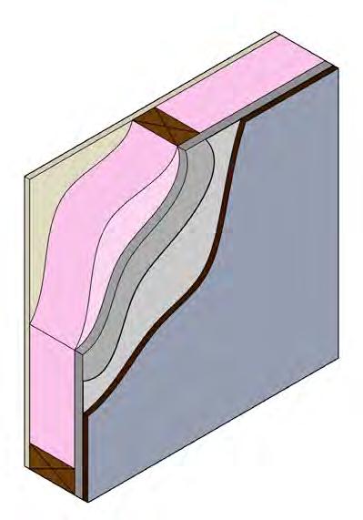
Insulation (Wall batts) Weathertex
Vapour permeable membrane
EXAMPLE FRL SYSTEM DESCRIPTION (60/60/60 Outside only)
EXTERNAL WALL SIDE
• Weathertex 9.5mm Cladding
• Vapour permeable membrane
• 1 layer 16mm FIRE WETSTOP
CAVITY INFILL:
• R2.5 GW Wall Batts
INTERNAL WALL SIDE
• 1 layer of 10mm STANDARD Plasterboard
Weathertex 6
UNDERLYING PLASTERBOARD SYSTEM CLADDING SYSTEM TIMBER FRAMING STEEL FRAMING Direct fix ✓ ✗
✓ ✗
✓ ✓
✓ ✓
✓ ✓
✓ ✓
1.3 Energy Efficiency
As is the case for all external lightweight cladding, Weathertex plays a small part in the thermal calculations. The following thermal rating examples are achieved using Weathertex standard systems with R2.0-R2.5 rated insulation. Higher R values can be achieved by using higher rated insulation, e.g. R2.7.
Weathertex 7
WALL CONFIGURATION RT (m2.K/W) EXTERNAL LINING FRAME INTERNAL LINING WINTER SUMMER Vapour Permeable Membrane Weathertex Cladding 90x45mm Timber Frame @ 600mm Centres R2.0 Batts 10mm Plasterboard 2.09 1.95 Vapour Permeable Membrane Weathertex Cladding 70x35mm Timber Frame @ 450mm Centres R2.0 Batts 10mm Plasterboard 1.98 1.89 Vapour Permeable Membrane 20mm Timber Cavity Batten Weathertex Cladding 90x45mm Timber Frame @ 600mm Centres R2.0 Batts 10mm Plasterboard 2.29 2.13 Vapour Permeable Membrane 20mm Timber Cavity Batten Weathertex Cladding 70x35mm Timber Frame @ 450mm Centres R2.0 Batts 10mm Plasterboard 2.20 2.09 Vapour Permeable Membrane 12mm Polystrene Thermal Break Weathertex Cladding 70x35mm Steel Frame @ 450mm Centres R2.0 Batts 10mm Plasterboard 1.74 1.68 Vapour Permeable Membrane 35mm Structural Timber Batten Weathertex Cladding 70x35mm Steel Frame @ 450mm Centres R2.0 Batts 10mm Plasterboard 1.93 1.84 16mm Fire Rated Plasterboard Vapour Permeable Membrane Weathertex Cladding 90x45mm Timber Frame @ 600mm Centres R2.5 Batts 10mm Plasterboard 2.73 2.59
1.4 General Requirements

The following installation instructions and guides are in addition to local and state regulations and the requirements of the National Construction Code (NCC). Weathertex provides construction detail drawings which should be used in conjunction with the instructions in this installation manual.
NOTE: All diagrams in this installation manual are for demonstration purposes only. Diagrams may omit some components for clarity.
Deviation from standard applications and requirements detailed in this Installation Manual or supplementary Weathertex Construction Details may void the manufacturer's product warranty. The product specific installation instructions in this manual are applicable to steel and timber frames for both direct fix and cavity systems. Preparation steps must be followed for direct fix to timber frame, ventilated cavity construction and steel frame construction.
1.4.1 STORAGE AND HANDLING
Weathertex products should be stored flat, under cover and on timber bearers spaced at maximum 600mm centres. When storing Weathertex outside, keep the stack clear of the ground and cover with waterproof materials to prevent water staining. NOTE: Weathertex factory stretch wrap is not designed to keep stored product weatherproof and should not be relied upon for primary weather protection.
Anodised aluminium products should be stored in a dry and flat position away from any potentially corrosive or incompatible materials. Timber or soft bearers at a distance no more than one metre apart should be used to support the product. Continuous exposure to moisture will promote corrosion. Metal edges and cut corners of the product can be sharp and may cause personal injury if not handled safely. Wear eye protection, gloves and protect skin when possible and when cutting avoid air borne metal fragments.
1.4.2 CUTTING AND WORKING WITH WEATHERTEX
Weathertex products are easy to cut and shape with a normal hand or power saw. Weathertex may be stacked two or three high for multiple cutting. Where required, edges may be trimmed with a smoothing plane or sandpaper. Holes are easily drilled with high speed drills or clean cutter bits. For best results break cut edges with a 2mm chamfer. Clean all dust from flashing as work progressed, as it may mix with water and create a brown runoff. Cut edges, holes and countersinks must be re-primed with a high quality tannin blocking exterior timber primer (water or solvent based). Excluding our Natural range.
The normal health and safety precautions should be taken when working with wood panel products. Machining equipment should be fitted with dust collection devices and used in well ventilated areas. Follow good hygienic and housekeeping practices. Wood dust can be vacuumed, shovelled or swept to avoid accumulation. If dust levels exceed Safe Work Australia Standards the wearing of a dust mask (AS 1715 and AS 1716) and safety glasses (AS 1337) is recommended. Storage and work areas should be adequately ventilated.
A Safety Data Sheet is available for download on the Weathertex website: weathertex.com.au
1.4.3 SITE, FOUNDATION AND FRAMING
Foundation design must comply with AS 2870 “Residential Slabs and Footings - Construction” and the National Construction Code (NCC). Timber or steel frames shall comply with the NCC. Where applicable, timber frames shall be constructed in accordance with Australian Standard 1684 - Residential Timber - Framed Construction. Steel frames must be erected in accordance with the manufacturer’s requirements. Frames shall be straight and true with studs at a maximum of 600mm centres. Timber shall be seasoned, as unseasoned timber is prone to shrinkage and can cause sheets and frames to move.
1.4.4 GROUND CLEARANCES
Lower framing timbers must be isolated from ground moisture by suitable damp-proof courses (DPC) or termite shielding. Similarly, cladding must not be placed in direct contact with masonry, brickwork or concrete. Where necessary, use strips of Alcor to isolate the materials. The bottom edge of Weathertex must be kept clear of surfaces in accordance with Table 1.4.4. Weathertex must not be installed in wet areas or where it comes in contact with standing water, and must allow for free flowing ventilation & drainage.
Weathertex 8
Product Impermeable ground2 Unsealed Ground3 Pre-Primed 50mm 150mm Natural 100mm 225mm
Table 1.4.4: Ground Clearance from base of cladding to Finished Floor Level1
1. Greater clearance may be required to comply with local building regulations, including but not limited to Termite Protection Provisions. For Termite Protection Provisions please see ‘Weathertex and Termite protection’ in section 1.4.9.
2. Impermeable ground (paved or concrete) The grade of adjacent finished ground must slope away from the building to avoid the possibility of water accumulation. Typically this is a minimum slope of 50mm over the first metre, however please refer to the minimum slope required from local building codes and regulations
3. Unsealed ground is any other case other than impermeable ground
1.4.5 MOISTURE MANAGEMENT AND FLASHING
Weathertex architectural panels are intended for use as internal and external cladding in standard stud wall systems. It is the responsibility of the Designer or Specifier to identify moisture related risks associated with any particular building design. Wall construction and design must effectively manage moisture, considering both the interior and exterior environments of the building, particularly in buildings that have a high risk of wind driven rain or are artificially heated or cooled. Adequate design of ventilation, flashings and moisture management systems must ensure that the wall cavity and the back of the Weathertex board will remain dry at all times.
In addition, all wall openings, penetrations, junctions, vertical and horizontal joins, connections, window heads, sills and jambs or other components, must incorporate appropriate NCC complying flashing for waterproofing to prevent moisture exposure on the back of the Weathertex. Flashing materials and methods must comply with the requirements of Weathertex, and where flashing materials are not specified by Weathertex refer to the Australian Standards &/or NCC. Failure to appropriately flash all penetrations will void the Weathertex Manufacturer’s Warranty.
On walls projecting from the roof line in upper storey construction, keep the bottom edge of Weathertex cladding 50mm clear of the lower storey roof claddings. Weatherproof with an approved flashing. For product specific details please refer to the relevant construction details on weathertex.com.au.
Unless specified flashing must have a minimum 15 degree fall away from the cladding, and the Weathertex must be installed with a minimum 10mm gap between the Weathertex and the flashing. Weathertex, under no circumstances permits the installation of the drip edge into any horizontal channel or accessory such as End Stops or U channels (slotted or unslotted).
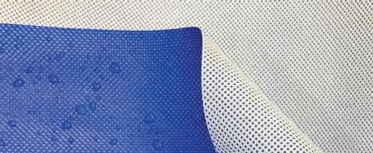
1.4.6 WALL SARKING REQUIREMENTS
Vapour permeable membrane must be used under all Weathertex external wall systems. The vapour permeable membrane allows for the controlled escape of vapour from within the building whilst restricting the ingress of liquid moisture. Weathertex recommends the use of Vapour permeable membrane in conjunction with the Weathertex Cavity Installation System to provide the best protection against condensation problems such as mould, timber rot, corrosion and loss of thermal resistance. Resources such as the ABCB Condensation Handbook and NATSPEC offer general information on condensation principles.
NOTE: Soft compressible products such as insulation installed directly between the front of the wall studs and Weathertex cladding is not compatible with Weathertex products and will void the product warranty.
Flammability index NOT MORE THAN 5
*sarking products are unsuitable if classed as a “Non-water Barrier” as per AS/NZS 4200.1 clause 5.3.5. and will void the Weathertex product warranty.
Weathertex 9
SARKING REQUIREMENTS FOR CLIMATE ZONES 2 - 8 Material Standard AS/NZS 4200.1
Standard AS 4200.2
Installation
MANDATORY PROPERTIES
Vapour Resistance Class 4 Water Barrier Passing AS/NZS 4201.4
1.4 General Requirements
1.4.7
RECOMMENDED VAPOUR PERMEABLE MEMBRANE PRODUCTS
The permeability and vapour resistance of materials should be considered in the context of their application. The designers/ architects/engineer should consider strategies to mitigate condensation risks in the design with relevance to local climate conditions. Suitable membrane products for moisture control in hot wet and humid conditions (Climate Zone 1) should be discussed with the membrane manufacturer.
Recommended accessories required for AS 4200.2 installation are Waterproofing tapes such as Bradford Enviroseal™ HighTack Adhesive Tape & Pro clima TESCON EXTORA® or equivalent, and Sill tapes such as Enviroseal™ Proctorwrap SLS Flexi Tape & Pro clima TESCON EXTOSEAL® or equivalent.


Product: Enviroseal Proctor Residential (RW) OR Commercial (CW)
Product: Ametalin VapourTech® Wall Residential & Commercial

1.4.8 CONSTRUCTION DETAILS
Product: Thermakraft Watergate Plus


Please refer to the Weathertex website for the complete suite of construction details for all products and applications. Scan QR code to view online.
1.4.9 WEATHERTEX AND TERMITE PROTECTION
The NCC specified the requirements for termite barriers. All of these requirements must be satisfied. Where the exposed slab edge is used as a part of the termite barrier system, a minimum of 75mm of the exposed slab edge must be visible to permit ready detection of termite entry.
Weathertex currently provides a warranty which protects against a variety of conditions including (but not exclusive of) the product supplied being fit for purpose, and will not rot, split or crack. In addition to this, Weathertex is warranted against termite attack, provided the following conditions are adhered to.
A termite mitigation plan complying with all local, state and federal requirements and best-practice guidelines must be in place and maintained from the time that the Weathertex is delivered to site and for the life of the product. Provided that the plan and its maintenance can be demonstrated, the normal Weathertex warranty at the time of purchase will apply to the Weathertex.
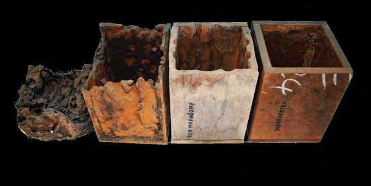
Samples removed from Termite Test after 2.5 years exposure
Weathertex 10 BLACKBUTT STANDARD HARDWOOD RED MAHOGANY WEATHERTEX
1.5 Painting: Pre-Primed
1.5.1 PRE-PRIMED PRODUCTS
PRIMER:
Weathertex factory primer is designed to be painted within 60 days of installation. Failure to do so can result in poor topcoat adhesion and will void warranty. Lightly sand any nibs or blemishes which have occurred during fixing. Cut edges, holes and countersinks must be re-primed with high quality tannin blocking exterior timber primer (water or solvent based). A spray primer is the most efficient method. It is also good practice to prime any timber mouldings, including corner stops and trims.
Trimtec aluminium accessories are protected by an anodised coating and can be left unpainted if desired. Due to their smooth surface, aluminium accessories should be etch primed if a topcoat is to be applied.
SURFACE PREPARATION - CLEANING & WASHING:
Clean surface of primed Weathertex products using a soft broom or soft lint-free cloth and wash down with sugar soap to remove salt, dirt, dust and grease or airborne contaminates. Do not vigorously scrub the surface nor use an abrasive or strong cleaning agent as you may burnish the paint surface and mark the primer finish. Wash down with fresh water and dry the surface with one final wipe using a soft dry lint-free cloth in the direction of the paint flow. Do not use high pressure washers as this can cause coating damage and water ingress into the wall cavity.
Not allowing the Weathertex to dry before painting is a common cause of paint failure. Failure to clean the surface may result in poor adhesion with topcoat and may void warranty.
1.5.2 PAINTING PRE-PRIMED PRODUCTS
PAINTING:
The primed surface of Weathertex products are suitable for the application of exterior grade water or solvent based topcoat paint systems. It is recommended to apply selected coating to a test area to confirm suitability. If compatibility of the selected topcoat is an issue, the surface may be primed with a suitable tannin blocking exterior primer per the coating manufacturer’s recommendation before painting. Contact the paint manufacturer for advice or information.
When top coating, apply a minimum of two coats of paint in accordance with the paint manufacturer instructions for mixing, film build, coverage and drying between coats. Temperature and wet weather will affect curing of coatings and consideration of site conditions at the time of painting is essential to ensure proper curing and adhesion. Paint additives may adversely affect the coating adhesion and durability and should only be used with the endorsement of the coating manufacturer.
PAINT COLOUR:
Weathertex hardboard products have 50 years proven durability in the harshest of climate zones. While there is no restriction on the vast array of colours to paint your home, it is important to understand the effect paint colours can have on the performance of construction products.
As Weathertex is a timber product, its dimensions will expand and contract with changes in moisture content. Dark paint colours can allow surfaces in warmer climates to become very hot in direct sunlight leading to loss of moisture and subsequent shrinkage of the panel. Selection of light paint colours with high Light Reflectance Values (LRV) will lead to better thermal efficiency of the building, improve the maintenance cycles of paint coatings and sealants while minimising the thermal expansion and contraction of all construction components. With darker paint colours we recommend prepainting the ends of the panel prior to installation of joining/corner accessories.


Weathertex 11
Painted PAINTING SPECIFICATIONS AT weathertex.com.au
Pre-primed (must be painted after installation)
1.6 Staining: Natural Range
1.6.1 NATURAL PRODUCTS
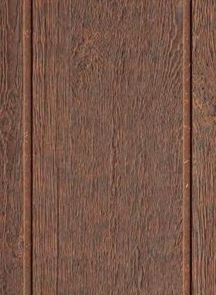
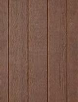
The Weathertex Natural Range are uncoated hardwood timber products that will fade to a rustic grey with UV exposure just like raw timber. Manufactured with a mixture of native Australian eucalypt species, the original colour and greying process can vary due to the seasonal variation of harvesting areas.
Weathertex Natural may be left raw to grey off, be stained with a quality decking stain to maintain the rich appearance of new timber / stained with a controlled erosion stain for timber to mimic greying off and maintained as per below.
NOTES:
1. Painting Natural range with a standard top coat (paint) finish or a clear coat will void the manufacturer’s warranty. If a top coat finish is to be applied, it must be onto Weathertex’s pre-primed products.
2. Varnishes, oils & clear coats are not suitable for external applications of Weathertex products. They do not provide adequate UV protection, their inflexibility can result in cracking/crazing and when externally exposed can cause irregular and blotchy surface aesthetics. It is the customer’s responsibility to confirm coating suitability from the coating manufacturer.
SURFACE PREPARATION - CLEANING & WASHING:
After installation, prepare the surface by removing dust and contaminants with an Oxalic Acid based timber cleaner solution. A soft broom or cloth may be used to gently scrub all surfaces. Wash down with fresh water and allow to completely dry. Not allowing the board to dry before coating is a common cause of coating failure. Failure to properly prepare the surface may result in poor adhesion and may void the coating manufacturer’s warranty. Never use high pressure washers as this can cause coating or even board damage and water ingress into the wall cavity.
1.6.2 STAINING NATURAL PRODUCTS
STAINING:
Apply 2-3 coats minimum of a recommended water based deck stain in accordance with the staining manufacturer’s application instructions. It is best to brush apply staining to ensure proper penetration into the woodsman featured surface. Cutting in should be performed after the first coat is applied to avoid a dry-line border in the finish. Weathertex Natural may also be left to lighten before staining for different colour results. Staining providers offer a wide range of colours that may be used and a test sample should always be performed to confirm colour expectations and performance before staining.
COATING WITH A CONTROLLED EROSION STAIN PRODUCT:
Apply a controlled erosion stain in a colour that is in accordance with the staining manufacturers instructions. Weathertex Natural may also be left to lighten before staining for different colour results. Staining providers offer a wide range of colours that may be used and a test sample should always be performed to confirm colour expectations and performance before staining.
WEATHERTEX LEFT NATURAL (UNCOATED):
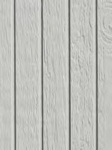
Left to weather naturally by the sun, the uncoated timber will lighten and “grey off” over time similar to raw hardwood. The degree and speed of colour change will depend on the intensity of UV and moisture exposure. The design of the installation must allow for consistency of sun & moisture exposure as shade lines caused by other features or differential moisture exposure will result in colour variation and inconsistent weathering patterns. When allowed to weather naturally some small black spots on the surface may become more visible. This is carbon which is inherent within raw timber and the manufacturing process. These small black spots are not mould and will not affect the performance or longevity of the product.
Unsealed Weathertex may be left unmaintained for a weathered look, or maintained by periodically cleaning with an Oxalic Based Deck cleaner. Periodic maintenance will ensure a more even finish and remove and surface contaminants.
NOTE: Natural Products are composed of unsealed natural hardwood timber which may occasionally exhibit tannin bleeding. Consideration must be taken if installing unsealed Weathertex products above porous or light coloured features.
Weathertex 12
1.7 Maintenance
Basic maintenance tasks include but are not limited to controlling vegetation and garden beds close to the installation, keeping gutters and pipes clear, addressing potential moisture damage due to overflows and replacement of penetrations, flashings and sealants used in installation as required.
Ground clearance maintenance is required to ensure clearances are maintained as per 1.4.4 and ensure there is no debris in contact with the bottom edge of the product.
To hold warranty on board edges, Weathertex recommends a detailed inspection report, showing removal of debris.
1.7.1 PRE-PRIMED PRODUCTS
The extent and nature of maintenance will depend on the geographical location and exposure of the installation. Regularly wash the painted surface with mild soapy water to remove dirt and grime to improve the performance of the coating. Never use high pressure washers as this can cause coating damage and water ingress into the wall cavity.
Thoroughly inspect topcoat paint work at the end of year 1 and repair areas of damage/coating breakdown according to the original paint specification or approved equivalent. Repeat inspection process at year 5 and based on the results of this condition survey make a decision on future maintenance actions, which may include touch up/repair of areas or a full re-coat
Generally, exterior surface coatings deteriorate by chalking rather than flaking. When repainting becomes necessary and the surface is unbroken, remove loose chalk by lightly sanding and follow the preparation steps above. Reapply new coatings in accordance with the paint manufacturer’s instructions.
1.7.2 STAINED NATURAL WEATHERTEX
The extent and nature of maintenance will depend on the geographical location and exposure of the installation to UV and moisture. Stained Weathertex must be periodically cleaned in accordance with the coating manufacturers maintenance instructions, which may be a yearly clean with an oxalic acid based timber cleaner. Do not use high pressure washers as this can cause coating damage and water ingress into the wall cavity.
Thoroughly inspect any coatings at the end of year 1 and repair areas of damage/coating breakdown. Repeat inspection process at year 3 and based on the results of this condition survey make a decision on future maintenance actions, which may include touch up/repair of areas or a full single coat.
Generally, semi-transparent decking stains and controlled erosion stains are softer and less UV resistant than regular exterior paint resulting in a 3 - 5 year recoating cycle. When re-coating becomes necessary follow the preparation and coating steps above. A darker / more opaque stain colour may be required in time to maintain the desired colour of the boards.
1.7.3 UNSEALED NATURAL WEATHERTEX
For unsealed Weathertex, the extent and nature of maintenance will depend on the geographical location and exposure of the installation to UV & moisture. It will also depend on the desired look of the unsealed product by the client. Unsealed Weathertex may be left unmaintained for a rustic faded unsealed timber look. We note that this may lead to dark markings from environmental conditions and lead to an inconsistent weathered look.
However, if you are after a more consistent weatherted look, we recommend a periodic clean with an oxalic acid based timber cleaner. Prepare the surface by removing dust and contaminants with an Oxalic Acid based timber cleaner solution in accordance with the timber cleaner manufacturers instructions. A soft broom or cloth may be used to gently scrub all surfaces. Wash down with fresh water and allow to completely dry.
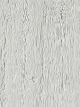
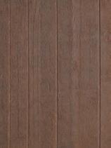
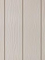
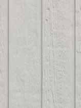
Recently built, this shows the beginning colour of Weathertex Natural boards.
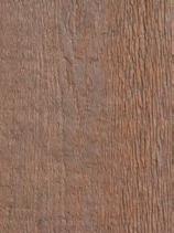
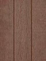
The board shows signs of lightening.
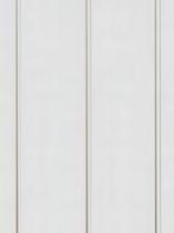
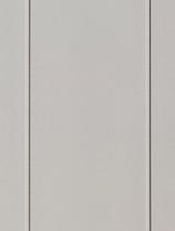
The boards are now very light, and are about to begin to be restored.
NOTE: Rate of fading may vary from above photos depending on environmental factors.
STAINING: Stain in the same direction that the boards run eg. Vertical for vertical cladding.
Weathertex 13
1.8 Cavity System
1.8.1 STEEL FRAMES
The following information applies to Weathertex installed on minimum 0.55 BMT steel frames. Installing Weathertex onto a steel frame is generally similar to installing Weathertex on a timber frame. There is however some differences of which the installer must be aware and the following section outlines the technical information unique to steel frame installation.
1.8.2 STEEL FRAME THERMAL BREAK REQUIREMENTS
The NCC has a mandatory requirement for Sole Occupancy Units of Class 2 buildings, Class 4 buildings, Class 10a buildings with a conditioned space and Class 1 buildings to meet Energy Efficiency Deem to Satisfy Requirements. It is also best practice to increase the energy efficiency of a building. In accordance with the NCC a rigid thermal break with R-value no less than 0.2 must be installed between the Weathertex external cladding and the metal framing members to separate both elements.
1.8.3 STEEL FRAME RECOMMENDED THERMAL BREAKS
A suitable membrane must be installed between the steel frame and battens; see section on Wall Sarking Requirements. The membrane must be held in place temporarily, using suitable fasteners or the timber battens (if applicable), before Weathertex is installed. Battens shall be wide enough to cover the face of the frame. For example if 90x45mm steel frame is chosen, the battens shall be 20x45mm at suitable length. Battens are to be installed over all studs. Below list of approved thermal breaks. Non-structural 20mm softwood timber battens — are easily installed to provide a suitable thermal break between Weathertex and a steel frame.
Final fixings will hold battens firmly in place but they must be temporarily fixed to the frame at 600mm centres before the cladding can be installed.
Alternative Rigid minimum R0.2 Thermal breaks—Extruded polystyrene strips, thermal break ventilated strips are an alternative to softwood timber battens for a thermal break solution. The extruded polystyrene strips shall be minimum 12mm deep. Nails or screws cannot be used to secure expanded polystyrene strips to the frame. Instead, double-sided adhesive tape or construction adhesive is suitable to hold the strips in place on the frame. Final fixings will hold extruded polystyrene strips firmly in place.
Structural 35-45mm timber battens—Structural H3 MGP10 timber battens can be structurally installed over the studs please contact Weathertex Customer Support team on 1800 040 080 or sales@weatertex.com.au for vertical structural batten attachment details.
1.8.4 STEEL FRAME FASTENERS
Appropriate fasteners must be used when installing onto steel frames. Stainless steel fasteners are not suitable for steel frame ceramic coated screws are a great alternative for our Natural product range. Alternatively structural timber battens can be installed over the frame to allow direct fix fastening. See the Fasteners Section and in relevant product section to select the correct fastener. Do not tap home under-driven gun Structnails as this can break the holding power of the fastener. Incorrectly shot nails should be removed and refastened at least 15mm away from the original fastener position.
1.8.5 TIMBER FRAME—CAVITY SYSTEM BENEFITS
To provide the best protection for your wall against moisture and mould related problems Weathertex highly recommends the use of a cavity fixing system. Fixing over the Weathertex cavity system provides the best defence for your internal lining, frame, insulation and cladding against sick home syndrome. A cavity system creates a space within the wall that allows airflow to remove any moisture that accumulates in this space either from wind driven rain or condensation.
1.8.6 TIMBER FRAME—CAVITY SYSTEM PREPARATION
Minimum requirements for fasteners must be followed when installing the Weathertex Cavity System. See the Fasteners Section when selecting appropriate fasteners. A suitable membrane must be installed between the timber frame and battens; see section on Wall Sarking Requirements. The membrane can be secured by the timber battens as they are installed along a wall. Care should be taken when installing bulk insulation to ensure the stud cavity is not over-filled. Over filling the stud cavity with bulk insulation will impinge in the cavity created by the cavity battens and hence reduce its effectiveness, and may void warranty.
Weathertex 14
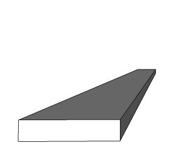
1.8.7 TIMBER FRAME WEATHERTEX CAVITY BATTENS
Cavity battens provide the separation between the membrane on the wall frame and the cladding. Weathertex provides and recommends the use of Weathertex Cavity Battens which are 1220 x 45 x 9.5mm, larger structural/non structural timber battens or vent strips. Check your local regulations and/or certifiers for recommended batten thickness. Cavity battens must be fastened to framework at a maximum of 600mm centres. Butt-join the stud battens leaving a 5mm gap.
When using cavity battens fastener lengths should be increased to accommodate the batten thickness. Refer to wind tables for further information. Refer to Weathertex Cavity Fix Construction Details when installing Weathertex cavity battens.
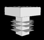
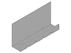
1.8.8 TIMBER AND STEEL FRAME CAVITY CLOSER
To protect against vermin and other material entering the cavity, the base of the cavity must be sealed using the Weathertex Large or Small Cavity Closer. A cavity closer must be installed at the base of the wall and above window heads and inter-storey flashings. The bottom of each batten is inserted into the cavity closer.
• Use 20mm Large Cavity Closer when using 20mm softwood timber thermal break battens (Steel Frame).
• Use 10mm Small Cavity Closer when using polystyrene thermal break strips (Steel Frame) and Weathertex cavity battens (timber Frame).
• Custom Cavity Closer are to be used for battens over 20mm with 3mm slots 20mm.
Fix the cavity closer to the base plate at 300mm centres. Butt-join cavity closers with max 2mm gap as required and ensure the closers are fixed in a straight, level line. It is important that the openings in the cavity closer are kept clear and unobstructed to allow free drainage and ventilation of the cavity.
12mm Polystyrene
Thermal Break Weathergroove
20-50mm
Small Cavity Closer
12mm Polystyrene
Thermal Break Weathergroove
20mm Pine
Thermal Break
9.5mm Cavity
Weathergroove
Weathergroove
Large Cavity Closer
20mm Pine
Thermal Break Weathergroove
1.8.9 TIMBER AND STEEL FRAME – HORIZONTAL SUPPORTS
Small Cavity Closer
9.5mm Cavity Batten Weathergroove
Horizontal battens are required to be installed over the noggins, base and top plates to allow for fastening of the panels, ensure proper drainage and ensure air pockets are not created. Horizontal battens must be installed flush with the front of the vertical battens. There are multiple options for horizontal supports.
• Timber batten/extruded polystyrene strips installed 50mm short each end of vertical stud on a 5 degree angle
• Small packers behind fasteners tilted at a minimum 5 degrees slope to allow drainage (see cavity spacer)
• Castellated Timber battens
• Ventilated battens
Weathertex 15
Batten
1.8 Cavity System
Ventilated battens—installed as per manufacturers instructions
1.8.10 STEP BY STEP
Step 4
Install chosen horizontal support (see section 1.8.9)
Timber Castellated batten
*Sarking and fasteners omitted for clarity 50mm 5o Angle
Cavity spacer installed on a minimum 5° angle with a 50mm gap between stud batten and spacer
Step 1: Install suitable membrane (see wall sarking requirements section 1.4.7
Step 2: Install cavity closer at base of wall (see section 1.8.8)
Step 3
Install chosen cavity battens on studs (see section 1.8.3)
Ensure required ground clearance is maintained (see section 1.4.4)
Once the wall has been battened out as per cavity construction details, Weathertex’s product specific standard fixing instructions shall be followed to install the cladding on to the frame.
Weathertex 16
1.9 Physical Properties
WEATHERTEX WEATHERBOARDS AND ARCHITECTURAL PANELS.
Weathertex weatherboards and architectural panels have been comprehensively tested to Australian and International Standards for verification of compliance to the Building Code of Australia.
MATERIAL DURABILITY PROPERTIES
The Product Specification Standard for Weathertex is AS/NZS1859.4 - Wet Processed Fibreboard for Exterior Conditions (HB.E).
THERMAL AND ACOUSTIC PROPERTIES
Where thermal and acoustically rated walls are required: Weathertex can be used as part of wall systems to meet your specific performance requirements. Thermal
Acoustic Properties (Rw) System Dependant
FIRE PROPERTIES
* A class 2,3 or 9c building with a rise in storeys of 2 may be of type C construction it requirements of C1.5 are satisfied.
MISCELLANEOUS PROPERTIES
Weathertex contains no silica, resins, binders or added formaldehydes and the results above confirm the amount naturally present in hardwood timber is negligible and well below the acceptance level of 1.0mg/L (E1).
Weathertex 17
PROPERTY STANDARD RESULT REQUIREMENT Dimensions AS NZS 4266.1 PASS ±2mm/m Density AS NZS 4266.1 1000 kg/m3 > 750 kg/m3 Surface Density (weight) 9.69kg/m2 Bending Strength AS NZS 4266.1 32 MPa > 20 MPa Modulus of Elasticity AS NZS 4266.1 4500 MPa > 2900 MPa Equilibrium Moisture Content AS NZS 4266.1 7.5% 7.5% ± 1% @ Factory gate Dimensional Stability –Hygro-Expansivity AS/NZS 4266.1 0.16% change in face dimensions over the range of 35%-80% relative humidity N/A Moisture Resistance AS NZS 4266.1 - 24 Hour submersion < 2% Swell 8% Max. < 6% Absorption 12.5% Max.
Classification AS/NZS 4266.16 Test Method:
mg/L
Formaldehyde
<0.07
– Emission Class Super EO
9.5MM COMPONENT
SYSTEM
Conductivity 0.22 W/mK
PROPERTY
VALUE WEATHERTEX
Thermal
Resistance 0.04 m2K/W
PROPERTY STANDARD RESULT REQUIREMENT Bushfire Attack Level (BAL) AS 3959 Up to and including BAL 19 BCA: Vol. 1 - G5.2 BCA: Vol. 2 - 3.10.5 Average Specific Extinction Area AS/NZS 3837 38.7 m2/kg BCA: Vol. 1 - C1.10 Material Group Number AS/NZS 5637.1 Group 3 BCA: Vol. 1 - C1.10 BCA: Vol. 1 - Spec C1.10 - 4 Early Fire Hazard Indices AS 1530.3 Ignitability : 12 Spread of Flame: 5 Heat Evolved : 4 Smoke Developed: 2 BCA: Vo1. 1 - C1.10 Fire Resistance Level (FRL) AS1530.4 Systems up to 120/120/120 available BCA: Vol. 1 - Spec C1.1 Combustibility BCA: Vol 1 - C1.1 Type C Compliant* BCA: Vol 1 - C1.1
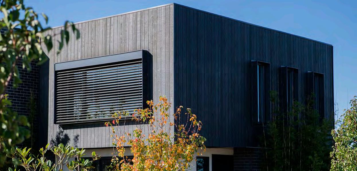
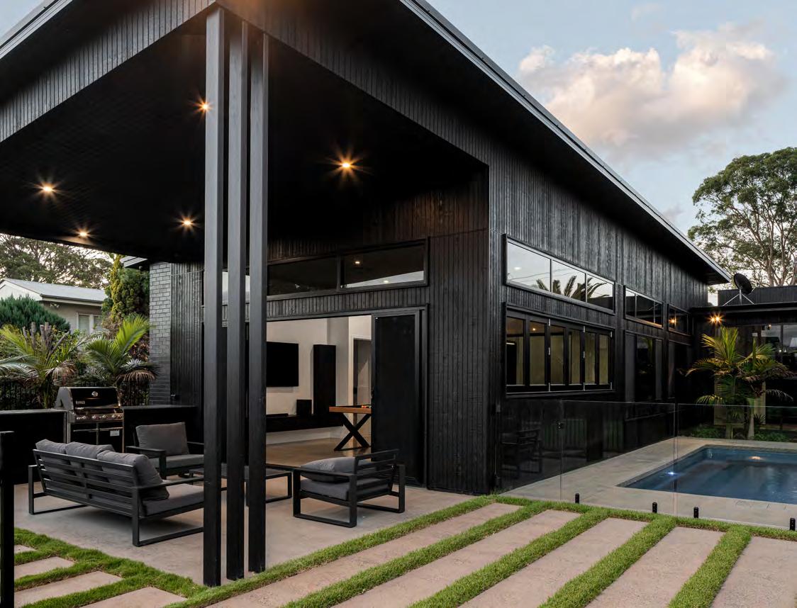
2.1 WEATHERGROOVE Panels
2.1.1 WEATHERGROOVE PANEL BENEFITS
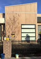
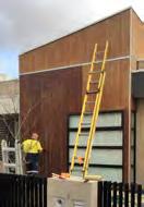
Weathergroove is the ideal choice for urban contemporary projects. It’s the tallest panel available in the Australian market, making this vertically grooved panel ideal for covering large areas in a short time and it’s versatility offers endless possibilities.
Features & Benefits
• Tallest panel size in Australia - 3.66m height.
• Off stud joining option enables minimal waste and less timber stud layout.
• Quick cost effective installation.
• Watertight mechanical joining system.
• Range of joining systems for various design options.
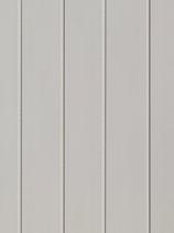
• Deep vertical lines for a bold expression.
• Universal edge which makes it possible to flip and reuse offcuts.
• Durable with 25 years warranty (pre-primed) and 10 years warranty (Natural).
2.1.2 WEATHERGROOVE PRODUCT RANGE
Thickness: All panels are 9.5mm thick Width: All panels are 1196mm wide
WEATHERGROOVE 75 SMOOTH
3660mm x 1196mm
WEATHERGROOVE 600 SMOOTH
3660mm x 1196mm
WEATHERGROOVE 300 NATURAL
3660mm x 1196mm
WEATHERGROOVE 75 WOODSMAN
3660mm x 1196mm

WEATHERGROOVE 1200 SMOOTH
3660mm x 1196mm 2745mm x 1196mm
WEATHERGROOVE 1200 NATURAL
3660mm x 1196mm
WEATHERGROOVE 150 SMOOTH
3660mm x 1196mm
3050mm x 1196mm
2745mm x 1196mm
WEATHERGROOVE 1200 WOODSMAN
3660mm x 1196mm
WEATHERGROOVE FUSION NATURAL
3660mm x 1196mm
WEATHERGROOVE 150 RUFF-SAWN
3660mm x 1196mm

WEATHERGROOVE FUSION SMOOTH
3660mm x 1196mm
WEATHERGROOVE 150 WOODSMAN
3660mm x 1196mm
3050mm x 1196mm
2745mm x 1196mm
WEATHERGROOVE 75 NATURAL
3660mm x 1196mm
WEATHERGROOVE 300 SMOOTH
3660mm x 1196mm
2745mm x 1196mm
WEATHERGROOVE 150 NATURAL
3660mm x 1196mm


Weathertex 18
Promoting Sustainable Forest Management PEFC CERTIFIED RESPONSIBLE WOOD CERTIFIED This product is from sustainably managed forests and controlled sources. Promoting Sustainable Forest Management PEFC CERTIFIED RESPONSIBLE WOOD CERTIFIED To view Weathertex product codes scan QR code.
2.2 Accessories
2.2.1 TRIMTEC
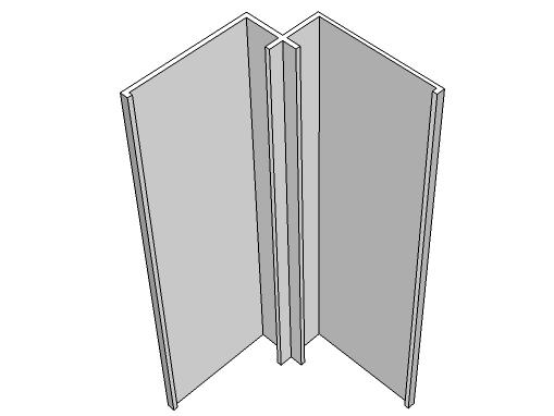
SMALL INTERNAL LF CORNER
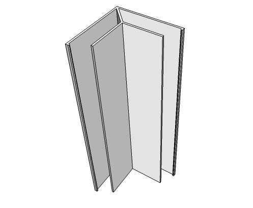
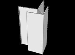
SMALL EXTERNAL LF CORNER
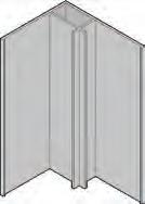
SMALL INTERNAL CORNER
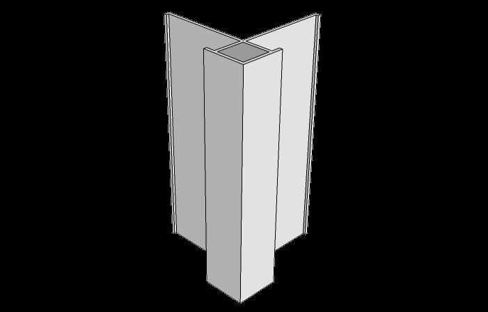
SMALL EXTERNAL CORNER
INTERNAL COMBO CORNER
a= Primelok/Classic
b= Weathergroove/Selflok/Rubix
EXTERNAL COMBO CORNER
b= Primelok/Classic
c= Weathergroove/Selflok/Rubix
L = 3660mm
a = 27mm
b = 11mm
c = 55mm
L = 3660mm
a = 27mm
b = 11mm
c = 31mm
L = 3660mm
a = 4mm
b = 11mm
c = 35mm
L = 3660mm
a = 17mm
b = 11mm
c = 35mm
L = 3660mm
a = 20.9mm
b = 10.7mm
c = 58.3mm
d = 48.3mm
e = 4mm
L = 3660mm
a = 27.3mm
b = 20.9mm
c = 10.7mm
d = 35mm
e = 45mm
Weathertex 19
ACCESSORIES *Made from anodised aluminium c a b PRODUCT PRODUCT IMAGE LINE DRAWING DIMENSION a b c
a c b a b c
c d a b e e d b c a
2.2 Accessories
2.2.2 TRIMTEC ACCESSORIES
WEATHERGROOVE JOINER
SMALL END STOP
SMALL Z FLASHING
For general horizontal joins
SMALL CORNER PLUG
Use with the Small external corner
L = 3660, 3050, 2745mm
a = 12mm
b = 5mm
c = 50mm
L = 3660mm
a = 27mm
b = 11mm
c = 45mm
L = 3670mm
a = 10mm
b = 10mm
c = 74mm
2.2.3 CAVITY WALL SYSTEM
L = 1830mm
a = Lrg 20mm = Sml 10mm
1220mm x 45mm
9.5mm thickness
For all cavity constructions
Weathertex 20
*Made
from anodised aluminium PRODUCT PRODUCT IMAGE LINE DRAWING DIMENSION
c b a
(Optional)
CAVITY CLOSER a
c b
a
b c
a
2.3 Fasteners
Refer to the Wind Tables below when selecting a fastener. For wind ratings above N4 and C2 please contact Weathertex Customer Support Team on (ph: 1800 040 080 or sales@weathertex.com.au). Installers must assure themselves that the appearance of the selected fastener is suitable for the intended use. Generally, head sizes in excess of 6mm or T and D head shaped nails may not produce a satisfactory finish on face fixed profiles.
• Ruff-sawn, woodsman & natural profiles - Stainless Steel ND Brad Nails using a Straight Bradder Nail Gun are recommended for direct fix timber. Ceramic Screws or suitably coated screws are required for steel frame with non-structural thermal breaks.
• Smooth profiles (can be used for Textured Weathertex) - 2.5mm Ring shank nails are recommended. Countersunk screws 2mm below the board surface & filled are recommended for completely concealed fixing of smooth profiles. Stainless Steel ND Brad Nails are not recommended for smooth profiles as they may create an undesirable surface finish.
2.3.1 RESIDENTIAL WIND TABLE - AS 4055 WIND CLASSIFICATION
Weathertex 21
*Reduce to 450mm centres for N3/C1 Weathergroove 75mm & Fusion MGP10 Timber Frame Fastener Type and Gauge Minimum Fastener Length Intermediate fastener stud and nogging maximum fastener spacing Wind Zone (Up to & including) Max Stud Spacing Centres Direct Fixed/Structural Cavity Batten Max 9.5mm cavity batten General Within 1200mm of building edges ND 14g Stainless Steel Brad Nail Finished Flush 38mm ND38 Stainless Steel Product Code:BM20053A & B20660 (Brad & Fuel pack) 50mm Paslode ND50 Stainless Steel Product Code:B20054A & B20665 (Brad & Fuel pack) 300mm N2 600mm 600mm N3/C1 600mm 450mm 150mm N3/C1 600mm 600mm* N4/C2 600mm 450mm ND 14g Stainless Steel Brad Nail Finished Flush 50mm Paslode ND50 Stainless Steel Product Code:B20054A & B20665 (Brad & Fuel pack) 300mm N2 600mm 600mm N3/C1 600mm 450mm N4/C2 600mm 300mm 150mm N3/C1 600mm 600mm* N4/C2 600mm 450mm 2.5mm Minimum Ring Shank Nail Natural - Stainless Steel PrimedGalvanised Finished Flush 40mm 50mm 300mm N3/C1 600mm 600mm* N4/C2 600mm 400mm 150mm N3/C1 600mm 600mm* N4/C2 600mm 450mm Treated Pine Screw Countersunk 2mm and filled see (2.3.4) 50mm Buildex Treated Pine 10g 8x50mm Countersunk Rib Head Screw Product Code: X503298 65mm 300mm N1 600mm 600mm N2 600mm 400mm 150mm N2 600mm 600mm N3/C1 600mm 450mm N4/C2 600mm 300mm Decorative Screw Finished Flush Bremick Vortex Decking Screw 5.9mmx50mm Bullet head Product Code: SMQC6500502 50mm 300mm N3/C1 600mm 600mm* N4/C2 600mm 450mm Decorative Screw Finished Flush 50mm Anchormark S2 Cladding Screw Product Code: SS-TTT 50mm 300mm N3/C1 600mm 600mm* N4/C2 600mm 450mm
2.3 Fasteners
2.3.2 RESIDENTIAL WIND TABLE - AS 4055 WIND CLASSIFICATION
G550
Steel
Iccons
0.75mm
0.75mm BMT Up to 12mm
Iccons Self drilling wafer coarse thread 10-16 x 40mm Finished Flush
2.3.3 COMMERCIAL WIND TABLE - AS/NZS 1170.2 WIND LOADS
Weathertex 22
Frame Extend fastener length when packing distance exceeds the following Fastener Maximum Stud Spacing Design Wind Pressure (Ultimate) kPa Maximum intermediate Stud & Nogging fastener spacing (mm) 300 200 150 MGP10 Timber Minimum Direct to frame 45 x 2.5mm Ring Shank Nail Paslode ND50 SS Product Code: B20054A & B20665 (Brad & Fuel pack) 600 1.5* 1.5* 1.5* 450 2 3.5 3.5 400 2.5 4 5 300 3.5 5 7 MGP10 Timber Minimum 10mm Batten Buildex Treated Pine 10g 8x50mm Countersunk Rib Head Screw Product Code: X503298 Pre Drilling required 600 1.5* 1.5* 450 1 1.5 2 400 1 2 2.5 300 1.5 2.5 3.5 0.55mm/G550 Steel Minimum Thickness 20mm Thermal Break SCROOZ 8g x 42mm FibreFix Cement Board Screw Product Code: FFSC0842T Pre Drilling required 600 1.5* 1.5* 1.5* 450 2 3.5 3.5 400 2.5 3.5 5 300 3.5 5 7 0.75mm/G550 Steel Minimum Thickness 12mm Thermal Break Iccons SD CSK COARSE C3 10-16 X 40mm screw Product Code: SDCSC1040C3 Pre Drilling required 600 1.5* 1.5* 1.5* 450 2 3 3.5 400 2 3 4.5 300 3 4.5 6 Note: Serviceability Limit State (SLS) wind pressures are limited to +1 kPa, -1.5 kPa for V2.2.1/FV1.1 Weatherproofing
kPa for Weathergroove 75mm & Fusion
*Reduce to 1
Steel
with Thermal Break
Frame
Frame thickness Thermal Break width increase fastener length for wider battens
Type,
and
Fastening Pattern Limitations Wind Zone (Up to & including) Max Stud Spacing Centres General Within Within 1200mm of building edges
BMT up to 20mm SCROOZ 8g x 42mm FibreFix Cement Board Screw Product Code: FFSC0842T Pre drilling required 300mm N2 600mm 600mm N3/C2 600mm 450mm N4/C2 600mm 300mm 150mm N3/C1 600mm 600mm* N4/C2 600mm 450mm
Fastener
Length
Gauge
0.55mm
BMT up
12mm
to
SD CSK COARSE C3 10-16 X 40mm Screw Product Code: SDCSC1040C3 Pre Drilling required 300mm N2 600mm 600mm N3/C1 600mm 450mm N4/C2 450mm 300mm 150mm N3/C1 600mm 600mm* N4/C2 600mm 450mm
Product Code: SDWAC1040C3 300mm N3/C1 600mm 600mm* N4/C2 600mm 450mm
Fastener & Wind Table Requirements and Recommendations
• Wind classification results have been conducted allowing for maximum packing distances specified in the tables. The fastener length must be increased to accommodate for the thickness of larger battens and/or additional packing materials to ensure the same penetration into the structural subframe.
• The above tables are relevant for on & off stud joining methods for timber and steel frames.
• All fasteners must be galvanised or suitably coated to resist corrosion for external application (Australian Standard AS 3566, Class 3 for screws). When installed in high corrosion zones such as coastal locations, fasteners (nails and screws) must be made of materials appropriate to the desired life of the system and geographical location. Stainless Steel Nails and Class 4 Screws may be necessary in these zones. The advice of the fastener supplier should be sought.
• For Natural range use stainless steel or suitably coated fasteners only. Galvanised nails are not permitted.
• The spans of the weatherboard shall be continuous spans of 2 spans or greater. Simply supported spans are not permitted.
• Span/150 serviceability limit state deflection criteria.
2.3.4 FASTENER FINISHES
Face fixed screw
Screw countersunk 2mm and filled
Flush fixed countersunk screw Face fixed nail Flush fixed nail Overdriven nail Under driven nail
2.3.5 FILLING 2MM COUNTERSUNK SCREW HOLES
(Recommended for Smooth Profiles only)
When countersinking screws, these must be pre-drilled countersunk 2mm below the board surface and filled with a high quality proprietary grade, flexible paintable filler.
When using a smart-bit style countersinking tool; the gauge of the screw must match the gauge of the tool to prevent movement issues. Screw holes should be spray primed after screwing with a solvent or water based primer and given adequate time to dry. Filler should be sanded and area re-primed prior to painting with a solvent or water based primer.
Weathertex recommends nail fixing when painting with dark paint colours (LRV 40% and lower) as dark colours lead to additional movement of construction components where filler may be prone to moving and becoming visible.
Failure of the product to hold its adhesive bond, is due to its inability to key to a surface. It is the responsibility of the builder/ installer to ensure that there is a good surface to bond to and the filler meets aesthetic expectations. Weathertex recommends a test area to confirm suitability.
*Refer to the Weathertex website for filler specifications, & please confirm with the filler manufacturer that the chosen filler is compatible with your specific project. **Non-flexible single pot & epoxy based fillers are not suitable and may crack and fail with movement of construction components.
Weathertex 23
2.4 INSTALL: Weathergroove
2.4.1 FRAME PREPERATION
The following product specific installation instructions are applicable for both direct fix (timber frame) and cavity fix (timber and steel frame). Installation instructions in this section are to be used in conjunction with information and requirements given in previous sections and all national and state building codes. Stud spacing to be selected by the building designer using the wind tables based on the wind classification to a maximum of 600mm. Sheet installed width nominally 1200mm.
2.4.1.1 OFF-STUD JOINING
Stud frame to be supported by flush noggings at maximum 750mm centres where an off stud join will occur. Check and straighten substructures as required.
Plan panel layout so off-stud joints occur approximately mid span between studs. The first panel may need to be a part panel.
If you are using horizontal joints you will need to ensure it is supported by a double or rotated noggings; please see z flashing details for additional frame requirements based on your choice of accessory.
For cavity installation see cavity systems (section 1.8). For direct fix install compatible wall sarking prior to installation, refer to AS 4200.2.
2.4.1.2 ON-STUD JOINING
Framing must be planned so all vertical joints occur on double studs or a rotated 90mm timber back block centred on the join.
Check and straighten sub-structures as required.
If you are using horizontal joints you will need to ensure it is supported by a double or rotated nogging; please see z flashing details for additional frame requirements based on your choice of accessory.
For cavity installation see cavity systems (section 1.8). For direct fix install compatible wall sarking prior to installation, refer to AS 4200.2.
2.4.2 BASE OF THE WALL
1. Establish a horizontal datum or base line at least 20mm below the base of the frame.
2. Install Alcor flashing for separation between Weathertex and masonry.
3. Install corners to the frame (note: Sarking must be installed first).
Suitable membrane (Refer to wall sarking requirements section 1.4.7)
Alcor flashing for separation from masonry
Datum
Ground clearance (Refer to general requirements section 1.4.4)
Weathertex 24
2.4.3 VERTICAL JOINING
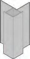
2.4.3.1 VERTICAL JOINING: ALUMINIUM WEATHERGROOVE JOINER
1. Inset the panel edge into the corner accessory, align the bottom edge with the datum and use a single fastener at a corner to temporarily hold the panel.
2. Adjust the panel so that the panel grooves are vertical before fixing off temporarily with a fastener at the opposite corner.
3. Slide the Weathergroove Joiner onto the rebated vertical joining edge and fasten off through the exposed back flange at the centre nogging with a flat head or screw (this will stop the joiner slipping after installation).
4. Install successive panels in the same way using the Weathergroove Joiner.
NOTES:
• Can be used on and off stud with all products.
• Do not fix through the Aluminium Weathergroove Joiner
• It is advisable to prepaint panel sides when using Weathergroove Joiners to avoid white lines either side of the Accessory after possible contraction of construction components in dry conditions.
• Only factory edges to be used in joiners
Weathergroove joiner (off stud)
Refer fastening
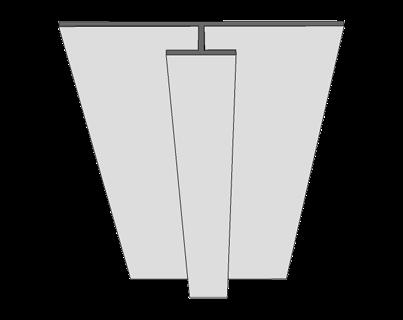
2.4.3.2 VERTICAL JOINING: ON STUD BUTT JOIN (NATURAL ONLY)
1. Install 100mm wide Alcor bitumen flashing over the sarking at each planned vertical joint.
2. Before installing the first panel, run a 5mm bead of suitable, flexible sealant along the length of the Alcor flashing to seal the edge of the Weathergroove panel.
3. It is standard to start at a corner with a cut panel to ensure the first joint is located on the planned double stud supports. Insert the cut edge into the corner accessory, align the bottom edge with the datum and use a single fastener at a corner to temporarily hold the panel.
4. Adjust the panel so that the grooves are vertically level before fixing off temporarily with a fastener at the opposite corner.
5. Weathergroove has a unique rebated edge that forms a regular groove when installed with an appropriate control gap. When joining panels, leave a 2mm gap in between panels to maintain the standard spacing of the grooves. Before installing the next panel, run a 5mm bead of suitable, flexible sealant along the length of the Alcor flashing to seal both edges of the Weathergroove panel.
NOTE: Natural products are composed of unsealed natural hardwood timber which may occasionally exhibit tannin bleeding. Consideration must be taken if installing unsealed Weathertex products above porous or light coloured features.
NOTE: Natural only - butt join not permitted with pre-primed.
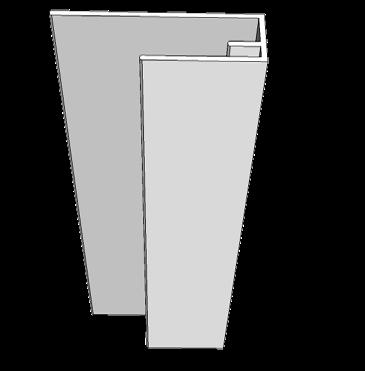
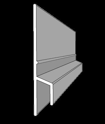
2.4.4 HORIZONTAL JOINING
Alcor flashing
Suitable sealant
Suitable membrane (section 1.4.7)
Refer fastening
Stainless steel fastenings
Alcor Flashing
Suitable sealant 2mm gap
Horizontal joins must be flashed using the Aluminium Z Flashing or Small Aluminium Z Flashing, refer to the Accessories Section. All horizontal joins must be supported by a double or rotated nogging minimum 70mm installed flush with the front of the frame. Install the accessory first before fastening off the top edge of panels. The standard Trimtec Z Flashing (instead of small Z Flashing) should be used where relevant between storeys to allow for frame settling and floor compression.
The top panels should be installed such that the bottom of these panels rest on the spacer bead of the z flashing. Install successive panels in the same way using the Z-flashing for horizontal joints.
NOTE: for natural Weathergroove ensure the Alcor flashing for the vertical join runs under the Z flashing.
Weathertex 25
2.4 INSTALL: Weathergroove
2.4.5 CONSTRUCTION DETAILS
Please refer to Weathertex Direct Fix Installation – Weathergroove, Drgs. of 15.04.20 (9 pages), and Weathertex 9.5mm Cavity Installation – Weathergroove, Drgs. 15.04.20 (9 pages) for details relevant to the Weathergroove Weatherproofing Appraisal.
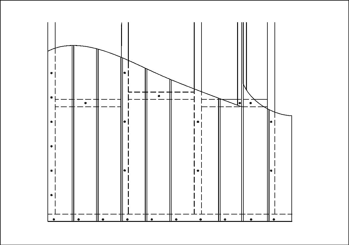
2.4.6 FASTENING
2.4.6.1 FASTENING: OFF STUD (JOINER ONLY)
Panels must be fastened at 150mm centres across the top and bottom of the panel and wall edge. All intermediate studs and noggings must be fastened in accordance with the appropriate fixing pattern and fastener installation requirements in section 2.3. Intermediate panel edges should be fastened to the nogging either side of the joint. For Cavity Systems these fastening points at noggins need to be packed with a piece of cavity batten to support the joint.
NOTES:
• Perimeter fixings should be a minimum of 12mm from the panel edge.
• Fasteners must not be placed in the panel grooves.
Fasten at noggings either side of joint
Fastening as per wind tables
150mm centre fastenings (top and bottom of panel and wall edge)
2.4.6.2 FASTENING: ON STUD (BUTT JOINS / ON STUD JOINERS)
Panels must be fastened at 150mm centres across the top and bottom of the panel and at studs along both vertical edges. All intermediate studs and noggings must be fastened in accordance with the appropriate fastener pattern and fastener installation requirements in section 2.3.
NOTE: Perimeter fastenings should be a minimum of 12mm from the panel edge and not be placed in the panel grooves.
Fastening as per wind tables
Fasten at 150mm centres along vertical joints
150mm centre fastenings (top and bottom of panel and wall edge)
Weathertex 26
OR OR
Panel to sit on top of nib
10mm minimum clearance
Weathergroove joiner (off stud)
2mm butt join (left open) back flashed
MANUFACTURER’S WARRANTY
1. Weathertex Pty Ltd A.B.N 67 084 713 986 (“Weathertex”) warrants that the Products supplied are of first quality, free from material defect in materials, design and workmanship, and in conformity with the technical specifications detailed in the published Weathertex Installation Guide that is current at the date of purchase. This statutory warranty applies for a period of 12 months from the date of purchase in addition to the following clauses.
2. Natural Board - Weathertex warrants that its Natural (Brown) Board Products will not rot, split or crack for a period of 10 (ten) years from the date of purchase when installed and maintained in accordance with Weathertex’s current published materials.
Pre Primed Classic Shingles Plus, EcoWall and Rubix Panel - Weathertex warrants that its EcoWall Products will not rot, split or crack for a period of 10 (ten) years from the date of purchase when installed and maintained in accordance with Weathertex’s current published materials.
Pre Primed Board - Weathertex warrants that its pre primed board Products will not rot, split or crack for a period of 25 (twenty-five) years from the date of purchase when prepared, installed and maintained in accordance with Weathertex’s current published materials.
3. A reference to Products in these warranty terms and conditions does not include accessory products listed “Accessories” in the Weathertex Price List (“Accessory Products”). Weathertex warrants that the Accessory Products will be free from defect in material and workmanship for a period of 7 years from the date of purchase. For the purposes of clarity, the warranties provided in clause 1 and 2 do not apply to Accessory Products.
4. The benefits to the purchaser given by the warranties set out in clauses 1 to 3 are in addition to other rights and remedies of the purchaser under Australian Consumer Law in relation to the Weathertex products and accessories.
CONDITIONS OF THE WARRANTY
5. The warranties provided in clauses 1, 2 and 3 are only available to the original purchaser (“Purchaser”) who provides Weathertex with proof of purchase and who makes the claim in writing within 30 days from the point in time when the defect becomes apparent or should have become apparent.
6. Weathertex will not be liable for any warranty claims made under clauses 1 and 2 if any of the following apply:
(a) the Products are not installed used or maintained in accordance with applicable instructions and/or specifications, including installation and site conditions provided by Weathertex (including the published Weathertex Installation Guide that is current at the date of purchase);
(b) the building in which the Products are installed does not comply with all relevant Building Codes and Regulations, Standards, and Council/Authority/Regulator requirements;
(c) the Purchaser has not complied with any service instructions which Weathertex may give or any subsequent request as to a modification of the Products which Weathertex may make from time to time in writing;
(d) the defect is caused by the use of materials, parts or accessory products that are not supplied, recommended, or approved by Weathertex;
(e) the Products are not maintained, prepared or installed by authorised installation contractors in circumstances where Weathertex has directed the Purchaser to ensure that the Products are maintained, prepared or installed by such authorised installation contractors; or
(f) the repair, rectification or replacement of the Products is required as a result of normal wear and tear or necessitated in whole or in part by the fault or negligence of any person other than Weathertex.
7. Further to clause 6 and without limiting clause 6, Weathertex under no circumstances will be liable for any claims, damages, or defects arising from or in any way attributable to:
(a) acts of God, fire, flood or other severe weather conditions or unusual climatic conditions;
(b) performance of paint/coatings applied to the Products;
(c) development of any algae, bacteria or fungi on the Products (whether on the exposed or unexposed surfaces);
(d) poor workmanship; or
(e) any other losses or damages (whether direct or indirect) including property damage or personal injury, consequential loss, economic loss or loss of profits arising in contract or negligence.
8. The Product is subject to natural variation in finish and presentation as a result of the manufacturing process. The purchaser / builder / installer must ensure the Product meets aesthetic expectations prior to installation. Subject to the terms and conditions of this warranty, after installation of the Product, Weathertex is not liable for claims arising from aesthetic surface variations if such variations were, or would upon reasonable inspection have been apparent prior to the installation.
REMEDIES
9. Should the Purchaser’s warranty claim made under clauses 1 and/or 2
be valid within the relevant warranty period, then the remedy provided by Weathertex will be limited to either of the following (where possible) as chosen by Weathertex:
(a) Weathertex replacing the Products provided the claim is accepted by Weathertex and subject to such replacement Products being available in the manufacturing inventory at the time the claim is accepted by Weathertex. Otherwise, Weathertex will provide such replacement Products when they become available.
(b) Weathertex repairing the Products provided the claim is accepted by Weathertex.
10. Should the Purchaser’s warranty claim made under clause 3 be valid, then the remedy provided by Weathertex will be limited to Weathertex replacing the Accessory Products provided the claim is accepted by Weathertex and subject to such replacement Accessory Products being available in the manufacturing inventory at the time the claim is accepted by Weathertex. Otherwise, Weathertex will provide such replacement Accessory Products when they become available.
11. The Purchaser is not entitled to any other remedies (that is apart from the remedies detailed in clauses 8 and 9) with respect to a warranty claim under clauses 1, 2 or 3.
12. This warranty cannot be relied upon by any other person and is not transferable.
13. Any replacement works will be conducted in accordance with the Building Codes and Regulations, Standards, and Council/Authority Regulator requirements applicable at the time of construction. Where the Building Codes and Regulations, Standards, and Council/ Authority Regulator requirements have changed after the Products were purchased, Weathertex will not be responsible for any costs associated with ensuring that the replacement works comply with the updated Building Codes and Regulations, Standards, and Council/Authority Regulator requirements.
14. Where an approved claim requires re-coating of the Products the Purchaser acknowledges and agrees to accept minor colour variations between the existing or original colour and the re-coated replacement Products or rectification areas.
15. Except as provided for in these terms and to the fullest extent permitted by law, all terms, statements, warranties and conditions whether express, implied, statutory or otherwise, relating to the Products, the Accessory Products, the subject matter of these terms or to these terms generally are excluded. Nothing contained herein excludes or modifies any rights the Purchaser may have under the Australian Competition and Consumer Act 2010 (or equivalent in other countries as determined by Weathertex in its sole discretion).
DISCLAIMER
16. Recommendations made by Weathertex are based on good building practice and are not a complete statement of all relevant data. As the installation of the Products is influenced by and relies on factors outside the control of Weathertex, Weathertex assumes no responsibility for works/ systems used in connection with the installation of the Products and their suitability to satisfy relevant Building Codes and Regulations, Standards, and Council/Authority /Regulator requirements.
17. Unless specifically stated otherwise, the warranties under clauses 1, 2 and 3 apply only to Weathertex products purchased and installed according to the Weathertex Installation Guide in Australia, New Zealand and the Weathertex International Installation Guide.
AUSTRALIAN CONSUMER LAW
18. Our goods come with guarantees that cannot be excluded under the Australian Consumer Law. You are entitled to a replacement or refund for a major failure and compensation for any other reasonably foreseeable loss or damage. You are also entitled to have the goods repaired or replaced if the goods fail to be of acceptable quality and the failure does not amount to a major failure.
MAKING WARRANTY CLAIMS
19. The claimant (being the Purchaser) must make all warranty claims in writing. The claimant must be the original purchaser of the Weathertex product and must retain the purchase receipt (in relation to the purchase of the product) as proof of purchase. Proof of purchase must be provided to Weathertex as part of the warranty claim.
Warranty claims (and claims for reasonable costs and expenses in making the claim as referred to in clause 18) can be addressed to Weathertex by post, fax or via e-mail as follows:
The Manager Weathertex Pty Ltd PO Box 21
Raymond Terrace NSW 2324
Phone 1800 040 080
Fax 1800 647 926
E-mail warranty@weathertex.com.au
20. Weathertex will respond to all warranty claims. This response may include an inspection by a Weathertex representative of the installed Product. The claimant will bear all costs and expenses of making the claim. However reasonable costs and expenses will be reimbursed to the claimant in the event that the claim is accepted by Weathertex.
As of 14th August 2020.
Weathertex 27

Weathertex 28 CONTACT WEATHERTEX FOR INFORMATION OR ADVICE 1800 040 080 | weathertex.com.au When specifying or installing Weathertex products, please make certain that you have the most current installation manual and technical information. To view the latest installation manual, scan the QR Code or visit weathertex.com.au Weathertex ® is made in Australia by Weathertex Pty Ltd ABN 67 084 713 986 PO Box 21, Raymond Terrace NSW 2324 UPDATED 22 ND AUGUST 2023 VERSION WC220823
Fusion Natural & Primelok Smooth NEWRELEASE WeathergrooveFusion
Weathergroove
