INCLUDES:
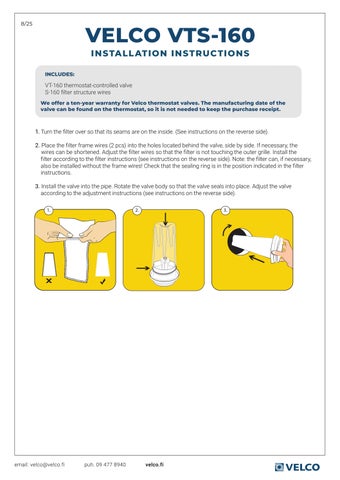
VELCO VTS-160
INSTALLATION INSTRUCTIONS
VT-160 thermostat-controlled valve
S-160 filter structure wires
We offer a ten-year warranty for Velco thermostat valves. The manufacturing date of the valve can be found on the thermostat, so it is not needed to keep the purchase receipt.
1. Turn the filter over so that its seams are on the inside. (See instructions on the reverse side).
2. Place the filter frame wires (2 pcs) into the holes located behind the valve, side by side. If necessary, the wires can be shortened. Adjust the filter wires so that the filter is not touching the outer grille. Install the filter according to the filter instructions (see instructions on the reverse side). Note: the filter can, if necessary, also be installed without the frame wires! Check that the sealing ring is in the position indicated in the filter instructions.
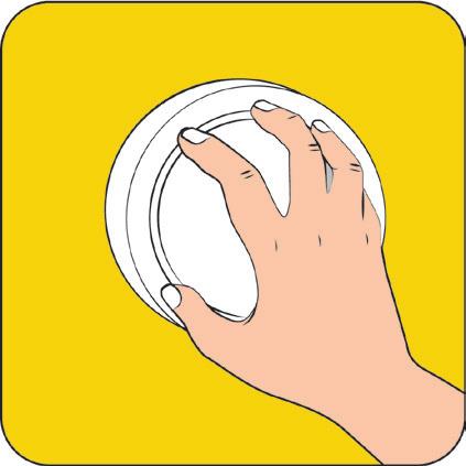
3. Install the valve into the pipe. Rotate the valve body so that the valve seals into place. Adjust the valve according to the adjustment instructions (see instructions on the reverse side).


-FILTER REPLACEMENT GUIDE
ALWAYS USE THE VELCO ORIGINAL FILTER TO ENSURE PROPERVENTILATION SYSTEM FUNCTIONALITY
The Velco VS-100 filter is made of high-quality Filtrete™ material developed by 3M. The Filtrete™ material uses exclusive 3-in-1 technology to pull in and trap unwanted particles, allowing cleaner air to flow through. Filtrete™ filters have an electrostatic charge that acts like a magnet to attract and capture microscopic allergens. Remember to changethe filter regularly. The filter must be changed when its surface is blackened, but at least once a year.
1. Take a grip from the valve body under the plate and carefully pull the valve out. Remove the dirty filter.
2. Ensure that the O-sealing ring is in the position indicated in the image.
3. Turn the filter inside out so that its seams are on the inside.

4. Thread the filter over the frame. Pull the filter over the sealing ring up to the valve body.
5. Push the excess filter fabric remaining above the valve into the gaps between the frame wires. Make sure the sealing ring is in place under the filter.
6. Place the valve back into position. Rotate the valve within the passage pipe to ensure a proper seal.
-VALVE ADJUSTMENT INSTRUCTIONS
IT IS IMPORTANT TO ADJUST THE VALVE ACCORDING TO THE INSTRUCTION BELOW TO ENSURE CONTINUOUS VENTILATION!
In Velco valves, there is a self-contained thermostat that adjusts the valve opening according to the outdoor temperature. Upon delivery, the valve is in the factory default setting. In the factory default setting, the valve disc is fully open at an outdoor temperature of +10 °C and closes as the temperature drops to -5 °C. To ensure continuous ventilation, adjust the plate during installation to prevent it from fully closing when the temperature falls below -5 °C.
1. The plate is in the factory default setting when you hear a click while turning it.

2. When the plate clicks, turn the plate at least half a turn counterclockwise to open it.

3. After turning the plate half a turn, the valve will not close as the temperature decreases but will remain slightly open by approximately 2mm.
NOTE: The minimum valve opening can be adjusted as needed. For instance, in a building without mechanical exhaust ventilation, it is recommended to turn the valve disc one full rotation counterclockwise from the click position.