No part of this document may be reproduced without the prior consent of the Client. This document is prepared in support of the Project.
David Bonnett Associates are not responsible for nor shall be liable for the consequences of any use made of this Report other than that for which it was prepared by David Bonnett Associates for the Client unless David Bonnett Associates provide prior written authorisation for such other use and confirms in writing that the Report is suitable for it. It is acknowledged by the parties that this Report has been produced solely in accordance with the Client’s brief and instructions and without any knowledge of or reference to any other parties’ potential interests in or proposals for the Project. Every effort has been made to acknowledge the source of photographs and illustrations; we apologise for any errors or omissions.
1. Introduction
1. Introduction
1.1
Purpose of the report
This Access Statement has been prepared by David Bonnett Associates (DBA) on behalf of Landsec Lewisham Limited (hereafter referred to as the ‘Applicant’) in support of a hybrid planning application for the redevelopment of Lewisham Shopping Centre (LSC) within the London Borough of Lewisham.
The description of the Development is:
Hybrid planning application for the comprehensive, phased redevelopment of land at Lewisham Shopping Centre and adjacent land, comprising:
Full planning application for (within Phase 1a) comprising the demolition of existing buildings, structures and associated works to provide a mixeduse development including the erection of a CoLiving building (Sui Generis) up to 23 storeys in height (Plot N1), and a residential building (Class C3) up to 15 storeys in height (Plot N2), associated residential ancillary spaces as well as town centre uses (Class E (a, b, c, d, e, f, g (i, ii)); and Sui Generis) together with public open space, public realm, amenity space and landscaping, car and cycle parking, highway works and the formation of new pedestrian and vehicle accesses, existing shopping centre interface works (the ‘Phase 1a Finish Works’), service deck modifications, servicing arrangements, site preparation works, supporting infrastructure works and other associated works.
Outline planning application (all matters reserved) for a comprehensive, phased redevelopment, comprising demolition of existing buildings, structures and associated works to provide a mixeduse development including:
• The following uses:
• Living Uses, comprising residential (Class C3) and student accommodation (Sui Generis);
• Town Centre Uses (Class E (a, b, c, d, e, f, g (i, ii)) and Sui Generis);
• Community and Cultural uses (Class F1; F2; and Sui Generis);
• Public open space, public realm, amenity space and landscaping works;
• Car and cycle parking;
• Highway works;
• Formation of new pedestrian and vehicular accesses, permanent and temporary vehicular access ramps, service deck, servicing arrangements and means of access and circulation within the site;
• Site preparation works;
• Supporting infrastructure works;
• Associated interim works;
• Meanwhile and interim uses and
• Other associated works.
The purpose of this report is to describe how the development has been designed with consideration and understanding of the principles of inclusive design and taking into account planning policy and guidance on inclusive design and access.
The Access Statement has assessed the detailed design of Plots N1 and N2 and the illustrative scheme for the outline component of the application. Further Access Statement would accompany the Reserved Matters application when they come forward.
Discussions relating to access have taken place throughout the pre-application process, covering access to, through and within the site.
Given the multi-leveled nature of the Proposed Development, ensuring access to those groups who need assistance has been central to the development of the masterplan. The Design Code sets out where in the masterplan that lifts must be provided to accommodate different access methods.
Details of the pre-application discussions are set out in Volumes 1, 2 and 3 of the DAS.
1.2 Method of review
The report describes the access provisions using a journey around the proposed development as follows:
• Arrival at the site;
• Approaches to the buildings;
• Entrance ways;
• Horizontal and vertical circulation;
• Access to facilities;
• Typical residential layouts; and
• The emergency evacuation strategy.
The statement does not describe or evaluate any part of the development that is used solely for inspection, repair or maintenance of any service or fitting, in accordance with Approved Document M. If a disabled person requires access to these areas as part of their work then their employer is expected to take all reasonable steps to ensure that there are no barriers to them carrying out their work. Any building adjustments that are required would be carried out at that time.
1.3 The standards
The current standards of the Approved Document Part M Volume 1 & 2 will be the applicable standards for the scheme in relation to access and inclusive design.
• The Building Regulations 2010, Approved Document M (Access to and use of buildings) Volume 1: Dwellings, HM Government, 2015 edition incorporating 2016 amendments. (Hereafter referred to as AD M Vol1).
• The Building Regulations 2010, Approved Document M (Access to and use of buildings) Volume 2: Building other than dwellings, HM Government, 2015 edition. Note: Amendments to AD M Volume 2 published in July 2020 take effect on 1 January, 2021 (Hereafter referred to as AD M Vol2).
1.4 Planning Policy context
1.4.1
National Policy
• National Planning Policy Framework (NPPF), Department for Levelling Up, Housing and Communities, September 2023
1.4.2 Development Plan
The current adopted Development Plan for the Site is comprised of:
• The London Plan: Spatial Development Strategy for Greater London, Mayor of London, March 2021.
The London Plan describes the expected standards of accessibility in all new developments in London.
POLICY D5: INCLUSIVE DESIGN
Development proposals should achieve the highest standards of accessible and inclusive design. They should:
1) be designed taking into account London’s diverse population
2) provide high quality people focused spaces that are designed to facilitate social interaction and inclusion
3) be convenient and welcoming with no disabling barriers, providing independent access without additional undue effort, separation or special treatment
4) be able to be entered, used and exited safely, easily and with dignity for all
5) be designed to incorporate safe and dignified emergency evacuation for all building users. In all developments where lifts are installed, as a minimum at least one lift per core (or more subject to capacity assessments) should be a suitably sized fire evacuation lift suitable to be used to evacuate people who require level access from the building.
Additional policies that aim to achieve the highest standards of accessible and inclusive design are:
• Local Development Plan, Lewisham Council, June 2011.
Policies that aim developments to achieve the highest standards of accessible and inclusive design are:
- Core Strategy Policy 1: Hosing provision, mix and affordability
- Core Strategy Policy 12: Open space and environmental assets
- Core Strategy Policy14: Sustainable movement and transport
- Core Strategy Policy15: High quality design for Lewisham
• Draft Lewisham Local Plan: Submission Version (January 2023), Lewisham Council.
Policies that aim developments to achieve the highest standards of accessible and inclusive design are:
- Policy QD2 Inclusive and safe design
- Policy HO5 High quality housing design
- Policy TR3 Healthy streets as part of healthy neighbourhoods
- Policy TR4 Parking
1.4.3 Other Material Considerations:
Mayoral Adopted Supplementary Planning Guidance (SPG) and London Plan Guidance (LPG):
• Large-scale purpose-built shared living, February 2024.
• Housing Design Standards, June 2023.
• Accessible London SPG, GLA, October 2014.
• The Planning for Equality and Diversity in London SPG, GLA, October 2007.
Mayoral Draft London Plan Guidance (LPG)
• Fire safety LPG (Draft), GLA.
1.5 Other references for inclusive design
Other documents referred to during the design of the scheme include:
• Housing Supplementary Planning Guidance, London Plan 2016 Implementation Framework, Mayor of London March 2016.
• Shaping Neighbourhoods Accessible London: Achieving an Inclusive Environment Supplementary Planning Guidance, London Plan 2011 Implementation Framework Mayor of London, October 2014.
• The Building Regulations 2010, Approved Document K (Protection from falling, collision and impact), HM Government, 2013 edition.
• British Standard 8300:2018 Design of an Accessible and Inclusive Built Environment, Part 1: External Environment - Code of Practice, Part 2: Buildings - Code of Practice, British Standards Institution, 2018.
• British Standard 9999:2017 Code of Practice for Fire Safety in the Design, Management and use of Buildings, British Standards Institution, 2017.
• Inclusive Mobility: A Guide to Best Practice on Access to Pedestrian and Transport Infrastructure, Department for Transport, December 2021.
• Inclusive Urban Design: A guide to creating accessible public spaces, David Bonnett Associates, BSI, 2013.
• London Cycling Design Standards, TfL, 2016.
• A Guide to Inclusive Cycling (second edition), Wheels for Wellbeing, 2019.
• Cycle Infrastructure Design: Local Transport Note 1/20, Department for Transport, 2020.
• The principles of inclusive design. CABE, 2006
• Designing for Accessibility, CAE/RIBA Publishing, 2012.
• Easy Access to Historic Buildings, Historic England, 2015.
Note:
DBA provides guidance and advice as access consultants. The consultancy does not officially approve designs, nor does it provide confirmation that a design complies with statutory standards. This remains the responsibility of the designers and the approvals authority.
1.6 Interpretation of the standards
Approved Documents M, K and BS 8300:2018 provide general access advice, but refer to other standards and regulations about specific aspects of buildings and their immediate surroundings. Therefore, several separately authored documents are referred to, including good practice guidance books written by specialists. Refer to Appendix 1 for more details.
There are no national regulatory controls governing extended external spaces and landscaping other than Best Practice Guidance. For primary routes and approaches to buildings Approved Documents M are taken as a bench mark for determining accessibility. With regards to streetscape and pavement design, guidance is provided by the Department for Transport’s Inclusive Mobility Guide and Transport Notes and BS8300:2018, Part 1: External Environments.
Access standards are in a continuing state of development because of changing expectations and legislation. The nature of these changing requirements and standards can result in anomalies and contradictions. Therefore it is important that access and inclusivity are considered and refined throughout the design process. The design of the scheme should seek to interpret these standards to provide the best possible level of inclusive design and this report describes situations and solutions where interpretation may be necessary.
1.7 The Equality Act
Statutory consents
When considering a reasonable adjustment to a physical feature , the Equality Act does not override the need to obtain consents such as planning permission, building regulations approval, listed building consent, scheduled monument consent and fire regulations. If the consent is not given, there is still a duty to consider a reasonable means of avoiding the feature.
Note that the Public Sector Equality duty requires public bodies to show evidence that they have considered how their decisions affect people with protected characteristics under the Equality Act.
Refer to Appendix 1 for further information.
Design standards
Service providers and public authorities carrying out their functions do not have to remove or alter a physical feature of a building for a period of 10 years from construction or installation if it accords with the relevant objectives, design considerations and provisions in Approved Document M. They may still need to consider a reasonable means of avoiding the feature if it presents a barrier to inclusion.
1.8 Management and maintenance
Once building works are complete, full accessibility will rely on effective facilities management.
Management items will range from provision of a good quality website, effective maintenance and staff training. Inspection of specialist devices and training of staff should become a regular element of facilities management. Access Management Plans can form part of a building operator’s on-going duties and will be required as part of the planning process.
1.9 Consultation
A number of parties have been consulted, during the design process, including community engagement.
For more information related to the public consultation process and outcomes refer to the Statement of Community Involvement.
1.10 Access aims
The Proposed Development is to be designed to be as inclusive as possible so that it can be comfortably and independently used by residents, people working in and visiting the development, and the wider community.
The Proposed Development has been designed in accordance the guidance in Part M standards and in line with the London Plan, and aims to incorporate the following access principles:
• To maximise access to all parts of the development, its facilities and services for people who are visitors and members of staff regardless of disability and as required by local, regional and national policy;
• To ensure that required standards for accessibility are met at the outset and as part of mainstream inclusive design wherever possible;
• To design inclusively, which means placing people at the heart of the design process and acknowledging diversity and difference;
• To address the anticipated, substantial increase of older people in proportion to the working-age population and their future needs;
• To meet the aims of the Equality Act (2010), where applicable.
1.11 Summary of access provisions
The key access provisions for the proposed development include:
• Inclusive environment - Proposals that considers the needs of all users including people with mobility impairments; people with vision impairments; people with neuro-diverse requirements; deaf people; older people; and small children.
• Public transport - excellent access to accessible public transport;
• Alternative means of access the site for people who cannot use public transport, such as the availability to be dropped off/picked up close to the entrances to the building;
• Accessible car parking - provision of Blue Badge bays for the three per cent of dwellings;
• Accessible cycle parking - provision of 5% of the cycle parking in the form of larger spaces that are able to accommodate larger, adapted cycles or bicycles used by disabled cyclists. Additionally, 20% of the provision will be in the form of Sheffield stands;
• Pedestrian routes - step-free approaches to all buildings, with suitable walking surfaces that are firm and smooth, and provision of resting areas at reasonable intervals;
• Landscape & Public realm - improved new public spaces that welcome the various users of the site, regardless their abilities or age;
BUILDINGS:
• Entrances - Direct and convenient approach at street level to all entrances;
• Circulation - Step-free access to all parts of the buildings, including terraces;
• Lifts - Access to all floors via at least two passenger lifts;
• Residential Amenities - All communal facilities have been designed to be inclusive and convenient to all;
• Toilets - Wheelchair-accessible sanitary facilities where sanitary accommodation is provided;
• Accessible housing - In line with the London Plan 2021, ten per cent of the dwellings of the total development will be designed to meet Building Regulation requirement M4(3) ‘wheelchair user dwellings’; and ninety percent of the dwellings of the total development will be designed to meet M4(2) ‘accessible and adaptable dwellings’;
• Emergency evacuation - Incorporation of an evacuation lift that will provide a safe and dignified means of escape for all on each core.
2. Sitewide Strategies
2. Sitewide strategies
2.1
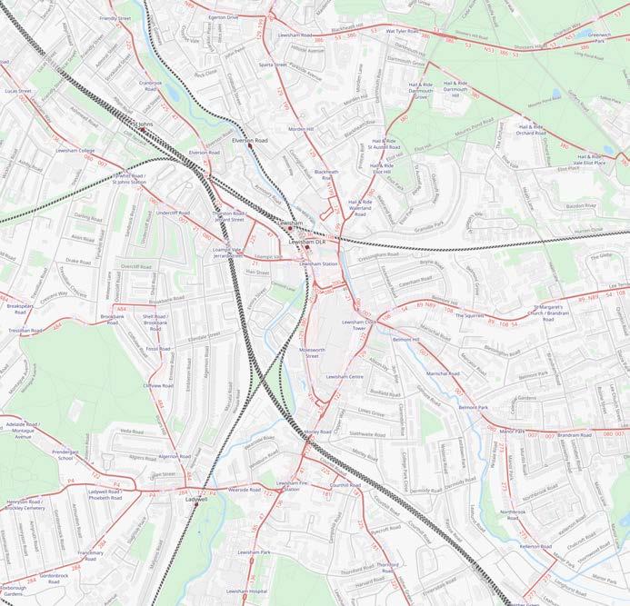
Site Context & Public transport connections
The proposed development site has a Public Transport Accessibility Level (PTAL) of 6b, which is defined as Excellent access to public transport.
The PTAL is an indication of the frequency, reliability and distance of public transport services close to a site; it does not take the accessibility of transport services into account. However, the PTAL is important to the access strategy because it is used to evaluate the reliance on cars that current and future users of the building are likely to have, with the implication that less reliance on cars corresponds to a greater reliance on public transport.
Buses
All areas of the development have convenient access to accessible public bus services. Bus services run along Lewisham High Street and Molesworth Street, with several bus stop in front of the site.
All London buses (except two ‘heritage’ routes) are accessible buses that ‘kneel’ to minimise height differences between the bus floor and pavement, and have ramps and space inside for wheelchair and pushchair users. However, not all disabled people can use them and therefore setting-down bays for taxis and private cars are essential.
Rail services
The nearest train station to the site is Lewisham Station at approximately 400m walking distance to the north. The station provides both DLR and Southeastern (National Rail) services. Lewisham Station has step-free access to all platforms.
Although the site is well connected to public transport services, the public transport is not accessible for all, and therefore the development should make the following provision for alternative means of access to the site, which are described in the following sections:
• suitable drop off points within 50 m distances form all entrances;
• accessible car parking close to the buildings they serve; and
• accessible cycle storage and storage/charging spaces for mobility scooters.
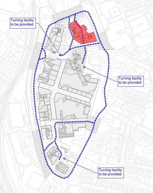
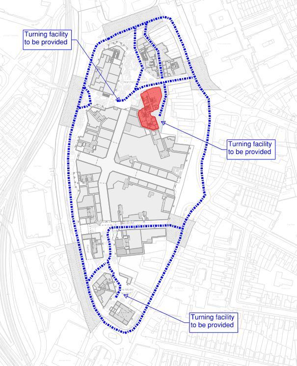
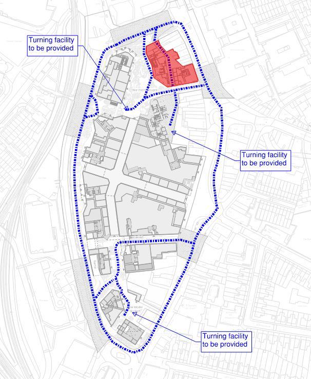
Fig.1 Transport Plan
2.2 Drop off points
Some residents and visitors will rely on community transport, taxis or minicabs, as a mean of transport. They should be able to be dropped-off/picked up close to the entrances. The Inclusive Mobility Guidance recommends that people should not walk more than 50 metres to approach the entrances.
Existing taxi ranks around the site are as follows:
• Lewis Grove, at 50m to the east;
• Albion Way, at 50m to the east;
• Lewisham Station, at 450m to the north.
These will continue to operate in line with the existing situation. Additionally, a new taxi/Blue badge dropoff area is provided on the southern servicing route.
Some entrances to retail units on the ground floor are at more than 50m from a vehicular route where people can be dropped-off/picked-up. Mitigations measures such as seating have been considered along pedestrian routes. For the shopping centre, it is assumed the entrance is considered the entrance to the mall rather the entrance to each retail unit. The shopping centre will include a rental service of mobility equipment, such as manual wheelchairs, power chairs and mobility scooters, so that people with restricted mobility can move around the site and enjoy the retail experience.
2.3 Car parking
2.3.1 Multi-storey Car Park
In line with local policies, the proposals are to remove the existing MSCP and provide only disabled car parking throughout the site for the residential use, on the basis that site is highly accessible by public transport.
Visitors/Residents to the development can use the car club spaces around the shopping centre. This is specially important for many disabled and elderly people who may rely on home-help and care staff.
2.3.2 Residential car parking
The London Plan 2021 Policy T6.1 Residential Parking requires a minimum 3% of the dwellings to have a designated disabled parking bay available from the outset, with an additional 7% of dwellings could be provided with one designated disabled parking bay if required in the future.
Because the Site is well served by accessible public transport, it has been considered that a provision of 3% residential parking across the masterplan is sufficient to meet the likely demand. Feedback from LBL and TfL has considered this approach acceptable.
Blue Badge parking for residents will be provided either at-grade or via consolidated car parks on the service deck. Consideration has been made to locate the M4(3) units within the buildings with direct access to car parks and in close proximity to residential cores.
2.3.3
Non-residential use car parking
Both the London Plan 2021 Policy T6.5 Nonresidential disabled persons parking and AD M Vol. 2, require that all non-residential elements should provide access to at least one on or off-street disabled persons parking bay.
Existing Blue Badge bay provision around the Site comprises 5 spaces on Molesworth Street car parking to the west of the Site, and 6 spaces on Clarendon Rise to the east of the Site. LSC MSCP currently provides 28 spaces, although only reaches 13 spaces occupied. Once the LSC MSCP is removed the remaining capacity would be 11 spaces across the town centre car parks.
Accessible car parking spaces will meet dimensional and other specifications as set out in AD M Vol.1 & 2 and local authority requirements.
All blue badge car parking bays, both within the Detailed and Outline Applications, will be fitted with active EV charging infrastructure.
Please refer to the Car Parking Management Plan by SLR for further information.
2.4 Cycle parking
Secure long-stay cycle parking are proposed for residential and commercial uses across the masterplan. Residential cycle parking is predominantly located at level 01 mezzanine with a small number of spaces at level 00 mezzanine. Long stay commercial cycle parking is located at grade inside buildings, while short stay commercial cycle parking is accommodate within Sheffield stands located within the public realm adjacent to dismount locations.
The proposed cycle parking provision will be in line with the London Plan with layouts designed in line with the London Cycling Design Standards (LCDS), including cycle parking spaces that can accommodate larger cycles, including adapted cycles for disabled people as follows:
• 5% of the total cycle spaces will be larger spaces;
• 20% of the total cycle spaces will be Sheffield stand types; and
• 75% of the total cycle spaces will be double stack stands.
Access to the mezzanine levels will be via dedicated cycle lifts where access is not available through the main lift cores, where the main lift cores provide insufficient redundancy for maintenance or downtime or where the main lifts are insufficiently sized for cycling. Cycle lifts will be minimum 1.2m by 2.3m, with a minimum door opening of 1000mm in line with TfL guidance, so that are able to accommodate all types of cycles. Consideration will be made
to reduce the number of doors cyclists need to negotiate along the route to the cycle stores. Routes to cycle facilities should be step-free and as short as possible to the lift cores.
2.5 Electric mobility scooters parking and mobility services
Consideration will be made to provide a covered and secured store for electric mobility scooters via a central hub as part of the estate management office, for residents/staff of the development who may rely on electric mobility scooters to move around and approach the buildings. The development will also consider other customer services such as rental services so that people with restricted mobility can move around the site and enjoy the retail experience.
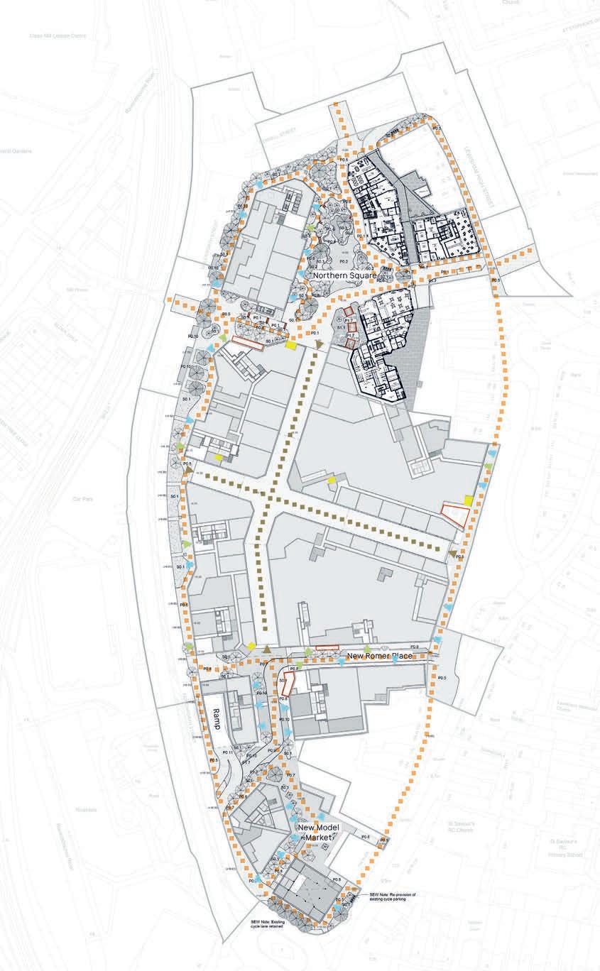
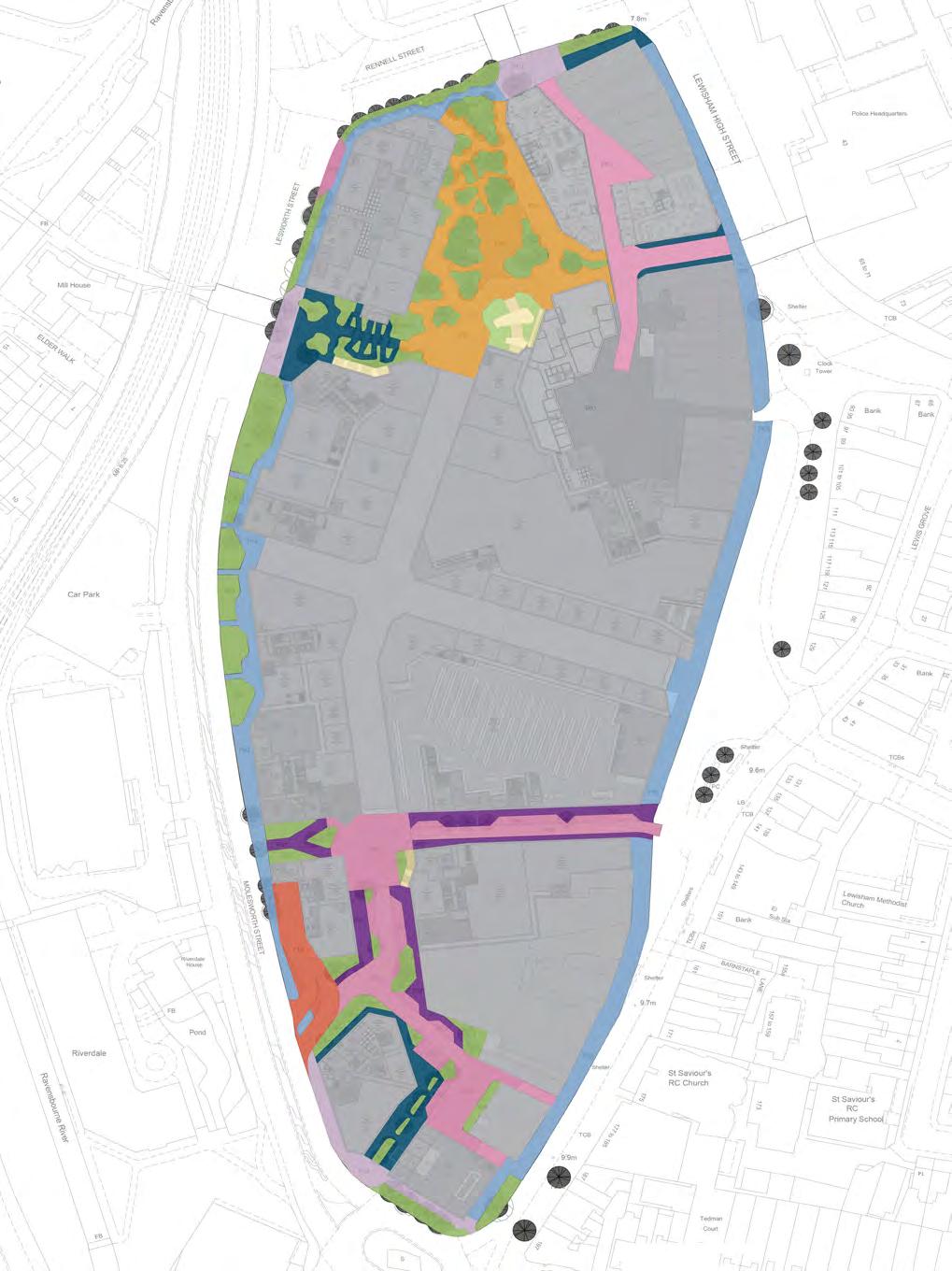
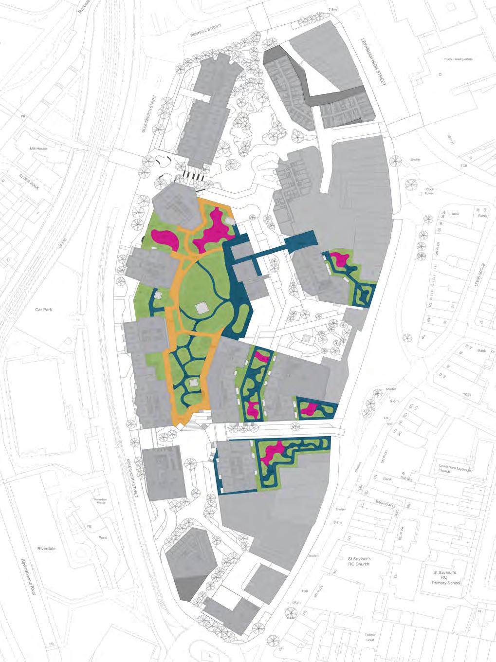
2.6 Public realm and Landscape proposals
All public realm and landscape areas have been carefully designed in consideration with the requirements of all users, regardless their abilities or age, so that they can be comfortably and independently used by residents, people working in and visiting the development, and the wider community.
The proposals are to increase permeability across the site by creating street-based routes and new open spaces. Main proposed connections will run north-south on the centre of the site, and additional connections will run east-west. New public open spaces are proposed at different levels with different uses and character: Northern Square, Eastern Square, and Sourthern Square at ground floor; The Street at first floor; and The Park on the second floor.
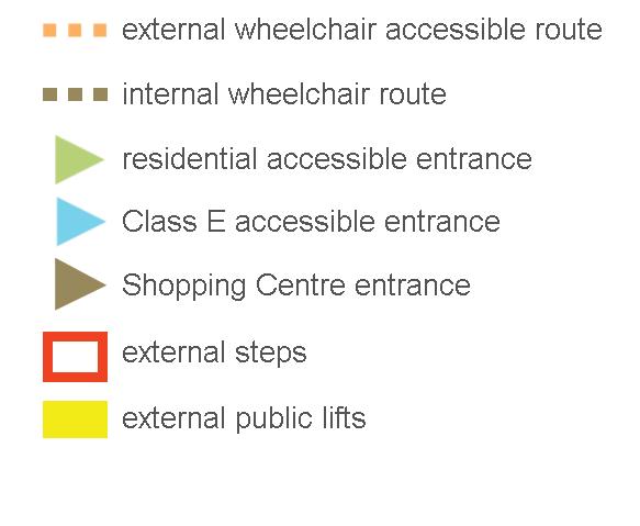
In line with good practice guidance from BS83001:2018, all new open spaces across the site have been designed as inclusive as possible, with access features including, but not limited to:
• Level or gently sloping routes for pedestrians, with gradients between 1:21 and 1:60, and level landing at every 500mm rise.
• Footpaths at least 1800mm wide, and where possible 2000mm wide, with walking surfaces that are firm and smooth.
• On Lewisham High Street and Molesworth Street, footways have raised kerbs with dropped kerbs and tactile paving on pedestrian crossings.
• Service roads are proposed to be a pedestrian first environment, but kerbs of 60mm are proposed around the vehicular route to ensure the safety and convenience for all users navigating these roads.
• Inclusion of greenery along Molesworth Street and Rennell Street footpaths to separate pedestrians from vehicles.
• Street furniture will be located outside access routes where possible so do not create barriers or hazards for people with impaired vision. And where street furniture is located within an access route, they will be clearly apparent and contrast visually with the background.
• There will be provision of resting areas at not more than 50m apart for people with limited mobility.
• Resting areas will provide a variety of seating options, including seating with armrests and backrests, seating with different seat height, seating that allows wheelchair users to transfer to a bench, and space for wheelchair users be integrated in the general seating provision.
• Seating will contrast visually with the background which it’s seen.
• Surface decoration that could be mistaken by steps, or very dark surfaces that may give the appearance of a hole to some people will be avoided.
• Lighting will be even, avoiding creating glare, pools of bright light or strong shadows.
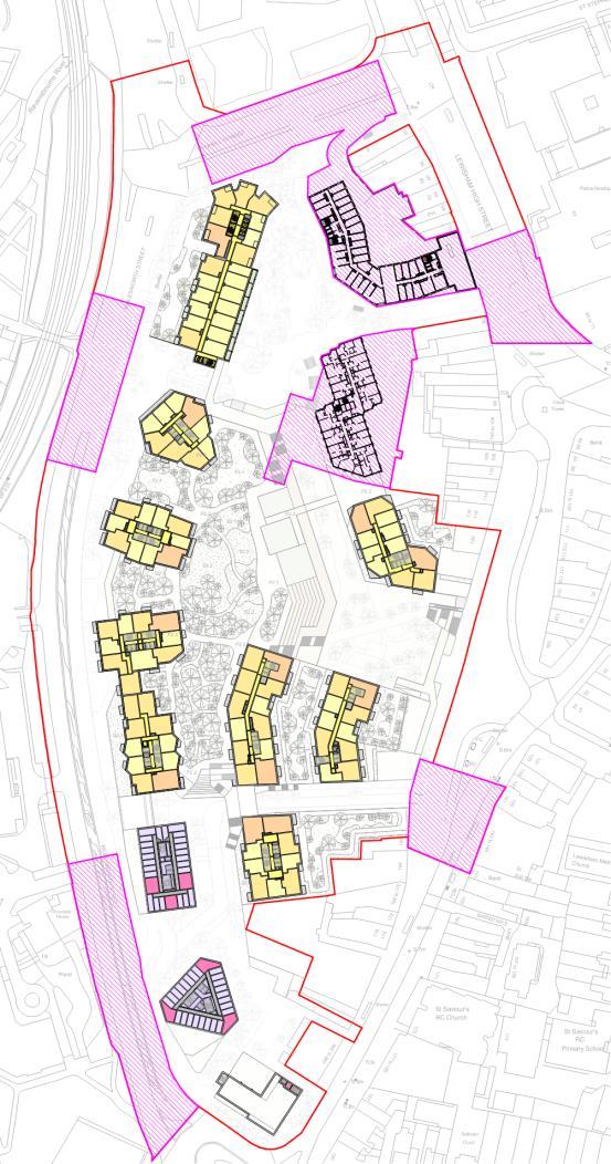
Fig.2 Pedestrian routes
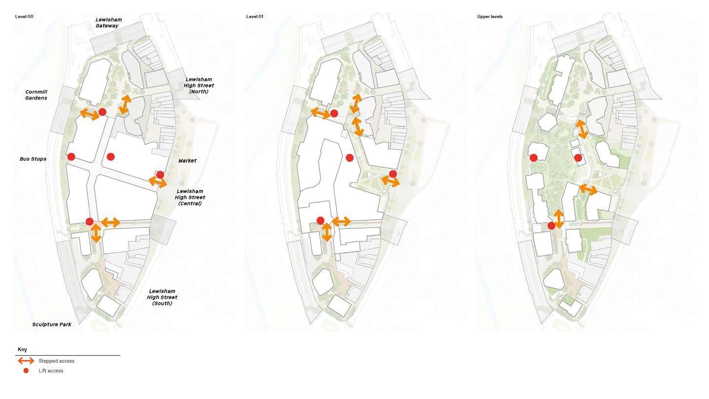
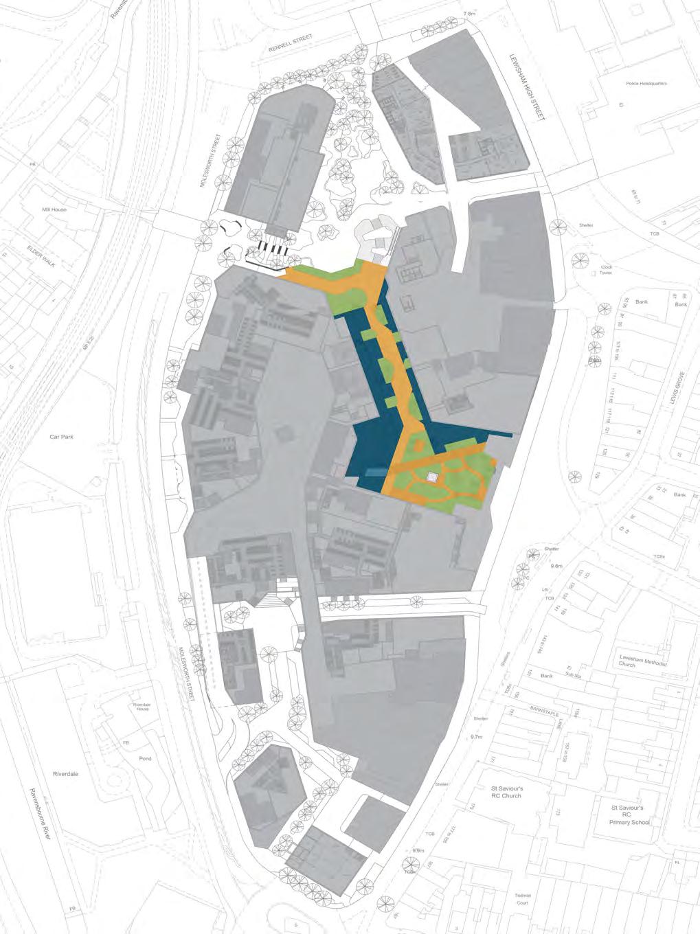
2.6.1 Vertical Access Strategy
The proposals are to create a multi level landscape that will connect the different public realm areas with existing areas outside the site. The Street is located at first floor and the Podium Park is at second floor.
Movement between levels will be via either stairs or public lifts located throughout the scheme to provide readily recognisable links from entry points into the development.
The provision and location of lifts have been carefully designed to aim that the experience and navigation through lift routes is as much similar as possible to stepped routes. Where possible lift access has been provided next to the stairs, but in some occasions, to optimise the lift provision, a lift core is accompanied by two stairs in close proximity. Public lifts will be easily recognisable and the wayfinding strategy will ensure that alternative step-free routes are indicated in all stepped routes.
Public lifts will exceed the minimum dimensions of 1100mm by 1400mm to accommodate several people and wheelchair users with large wheelchairs. There will be two lifts on each vertical core for resilience of the step-free routes.
Fig.3 Vertical access strategy
2.7 Sitewide public facilities
The Proposed Development aims to deliver the following public facilities to improve the experience of all users, specially disabled people.
• Meeting and information points. Informal meeting points, located at places such as junctions of pedestrian routes, near landmarks and at the entrances to key buildings or amenities. Meeting points will allow adequate space for people to congregate, rest and socialize without obstructing pedestrian or vehicular movement.
• Quiet space. A dedicated space for calm, tranquillity or contemplation, to benefit individuals that can feel sensory/neurological overload.
• Sanitary accommodation. Public toilets will be re-provided in phase 2 close to the new shopping centre entrance prior to the closure of the existing facilities. These will include a variety of facilities, including: unisex wheelchair-accessible toilets, WC for ambulant disabled people, a Changing Places toilet, and family toilets and facilities.
• Assistance dog toilets/spending areas
Provision to allow people who use assistance dogs to toilet their dogs in a safe and clean manner.
3. Outline element - Buildings
3. Outline element - Buildings
3.1 Inclusive Design principles of the buildings
This section outlines the approach to inclusive design for the buildings and how they will meet the relevant standards and regulations. The list is not intended to be an exhaustive list of compliance but a set of parameters that have informed the design at this stage.
Entrances
• Step-free access to all entrances and direct approaches clear of obstructions.
• Entrances are recessed for easy identification and provision of weather protection. Residential entrances are covered by at least 1200 x 1200mm.
• There is a 1500 x1500mm level landing in front of all entrances.
• Non-residential entrance doors provide a clear opening width of at least 1000mm. Residential doors provide a clear opening width of 850mm. Doors will be automated if the opening force exceeds 30N.
• All entrances will be designed to meet the guidance of AD M. Details to be developed at the appropriate stage.
Horizontal circulation
• There are no level changes across floorplates.
• Communal corridors will be 1500mm wide in line with the London Plan Housing Design Standards.
• Internal doors will be minimised, and where possible will be held-open. Doors will be automated if the opening force exceeds 30N.
• Doors in communal routes will have a clear opening width of 850 mm through a single leaf door, or one leaf of a double leaf door; and will have 300 mm clear space to the leading edge on the pull side of the doors and 200 mm clear space in the push side.
Vertical circulation
• Provision of at least two passenger lifts to access all floors.
• All car lifts will be at least 1100 mm x 1400 mm.
• There will be a clear landing of at least 1500 x 1500 mm in front of all lifts.
• Passenger lifts to be designed to meet the guidance of AD M and BS EN 81-70. Details to be developed at the appropriate stage.
• All new stairs (except those solely serving plant areas) to be designed to meet the requirements of Part K for ‘general access stair’. Details to be developed at the appropriate stage.
• Internal ramps will be avoided.
Access to terraces
• Step-free access to all terraces and balconies.
• Communal terraces to have a minimum width of 1800mm to allow two wheelchair user to cross each other. Private terraces to be minimum 1500mm wide.
• Doors to terraces to have accessible thresholds.
Communal amenities
• Any communal amenity provided for the benefit of residents and visitors will be accessible to all.
• Where appropriate, sanitary facilities will be provided to suit a wide range of users, including wheelchair-accessible WCs, and WC cubicles for ambulant disabled people.
• Access to refuse stores will be step-free.
Emergency egress
• In line with the London Plan 2021, evacuation lifts will be provided in all cores to provide a safe and dignified means of escape for all building occupiers.
• Provision of safe refuge spaces on each lift protected lobby to anyone in need of assistance to speak with building management staff.
3.2
Accessible Housing
The indicative scheme is for up to 1600 homes with 119 dwellings within Building N2 in the detailed component.
In line with the London Plan 2021, at least ten per cent of the dwellings will be designed to meet Building Regulation requirement M4(3) ‘wheelchair user dwellings’, and the rest will be designed to meet Building Regulation requirement M4(2) ‘accessible and adaptable dwellings’.
Wheelchair user dwellings will be distributed throughout the development, across type, size and level, as far as possible to ensure that:
• Wheelchair user units are not clustered together; and
• Wheelchair users have as much choice about the location and level of their home as anybody else, as far as possible.
The provision made to meet Building Regulation requirement M4(3) can be of two types:
• Wheelchair adaptable dwellings: the access provisions allow a simple adaptation of the dwelling to meet the requirements of occupants who use wheelchairs.
• Wheelchair accessible dwellings: the access provisions meet the requirements of occupants who use wheelchairs.
Wheelchair adaptable dwellings are intended to be capable of becoming wheelchair accessible through easy adaptations that do not require structural or service modifications, or moving walls. They have greater flexibility in their internal layout, such as bathroom or kitchen layouts.
Wheelchair accessible dwellings are intended to be readily usable by wheelchair users at the point of completion.
Wheelchair user dwellings will normally be designed as wheelchair accessible only where the local authority is responsible for allocating or nominating a person to live in that dwelling.
4. Detailed element - Phase 1a
Plot N1, Co-living Scheme
4. Detailed element - Phase 1a, Plot N1
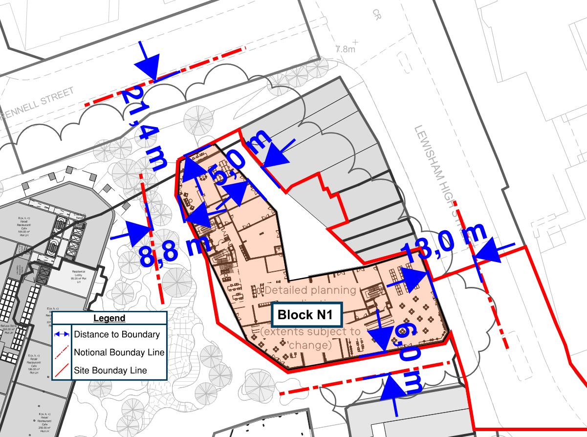
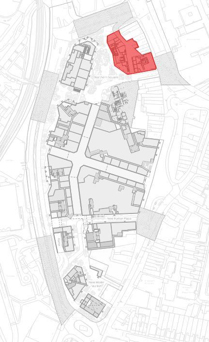
Plot N1 is part of Phase 1a and sits on the northeastern corner of the site, along Rennell Street and Lewisham High Street adjacent to Lewisham House and adjoining the new Northern Square public park. The north elevation faces the recently completed Lewisham Gateway development. A public route between N1 and Lewisham House offerd continuity of the new thoroughfare stretching from Lewisham’s railway and DLR stations across Rennell Street to the shopping centre.
4.1
Approach to the building
Main pedestrian route to the building entrance are either from the Northern Square or from Lewisham High Street via the new service road. Both routes are level.
Northern Square is a pedestrian only route with suitable ground surface and seating and planting along the route.
The service road have unobstructed, 1800mm-wide pavements on both sides of the vehicular route. Pedestrians will be separated from the carriageway with 60mm high kerbs with crossing that include tactile paving and dropped kerbs.
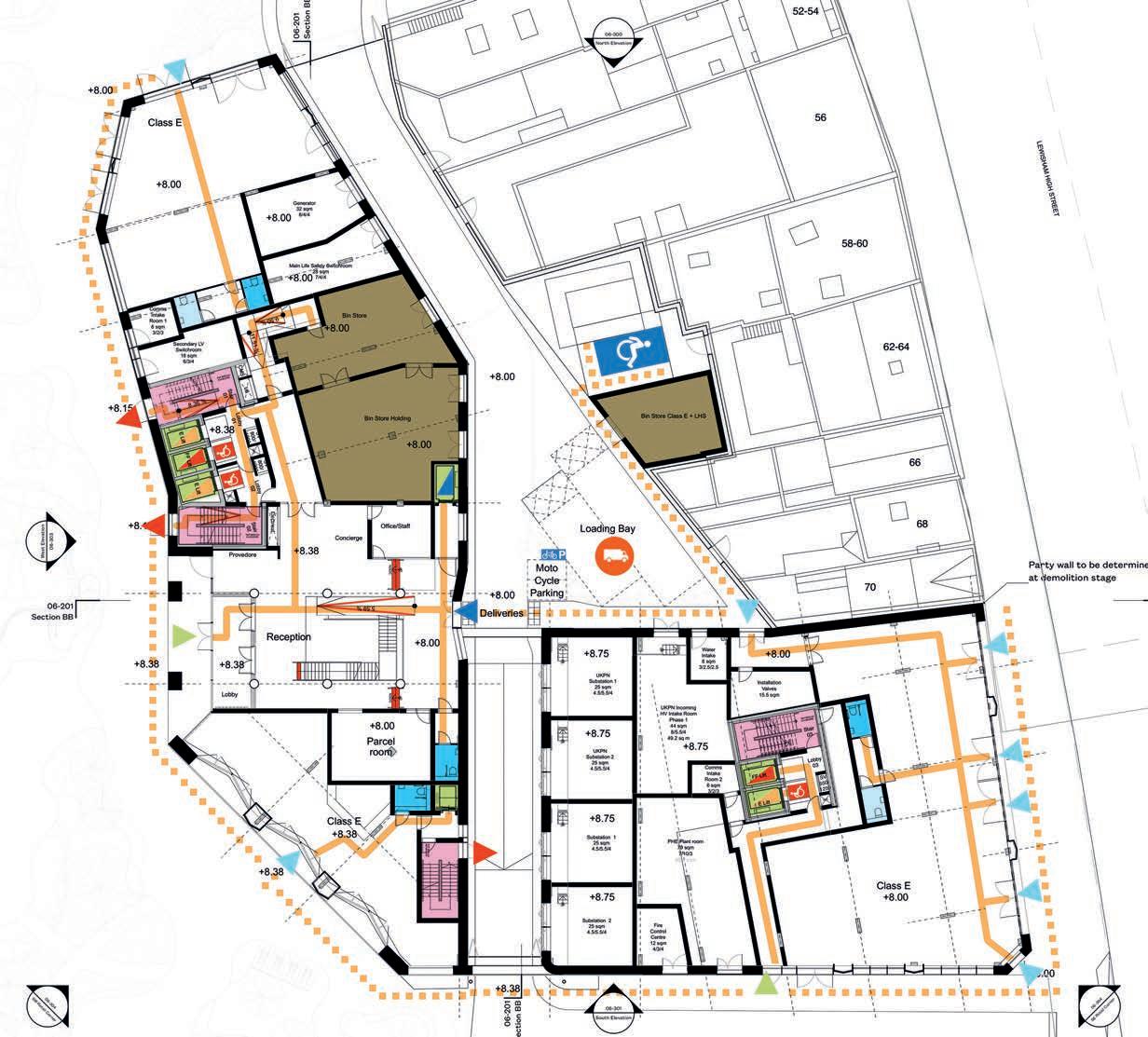
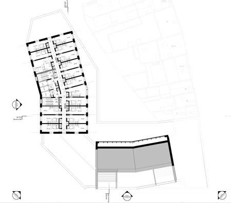
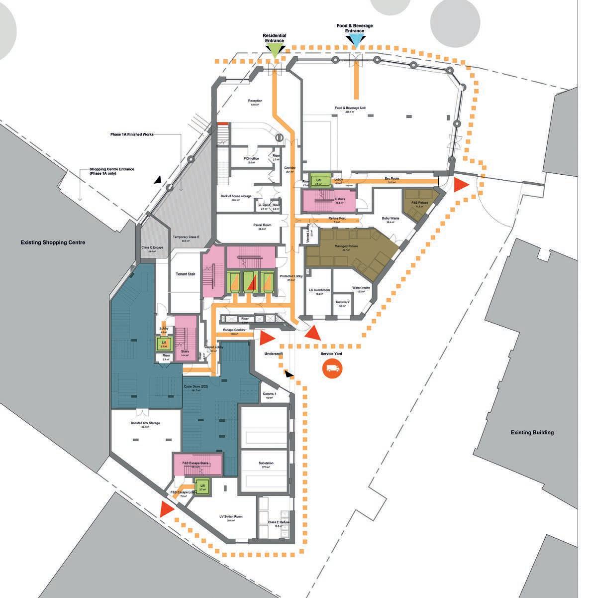
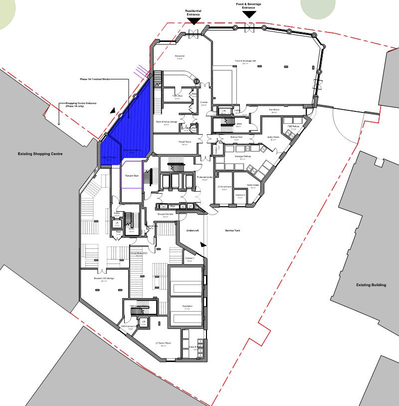
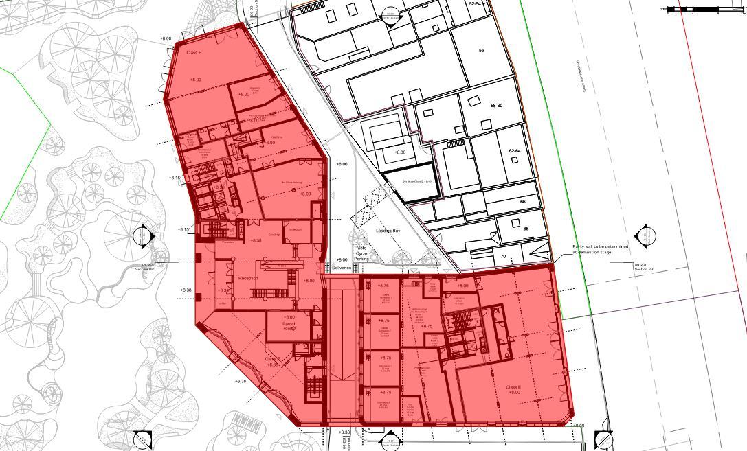
Fig.4 N1, Proposed Ground floor
4.2 Car parking and Drop-off point
Plot N1 will be car-free with the exception of the provision of 1 Blue Badge bays (BB) located at the rear of the building. Vehicular access to this bay is through the service road. A safe pedestrian route, including a pedestrian crossing, will be provided from the BB bay to the rear entrance of the building. The rear entrance into the building has been recessed to provide a landing before the pedestrian crossing where people can assess whether is safe to cross or not.
People who rely on community transport, taxis or minicabs as a mean of transport to the site, will be able to be dropped-off/picked-up on the service road at the south of the site at 50m from the main entrance to the building. Routes are level and with suitable width and ground surfaces.
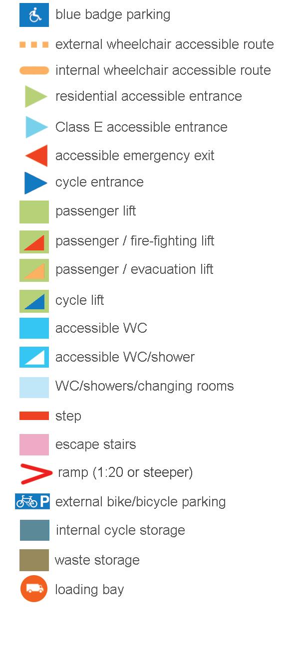
4.3 Cycle parking
A secured and covered cycle store is provided on level 00 Mezzanine accessed via a dedicated cycle lift. Proposed cycle is 1.2m wide by 2.3 m as recommended by LCDS. Access to the cycle lift at ground floor can be either be accessed from the main foyer or from the rear entrance to the building.
The proposed cycle parking provision will be in line with the London Plan with layouts designed in line with the London Cycling Design Standards (LCDS), including cycle parking spaces that can
accommodate larger cycles, including adapted cycles for disabled people as follows:
• 5% (18no.) of the total cycle spaces will be larger spaces;
• 20% (68no) of the total cycle spaces will be Sheffield stand types; and
• 75% (250no.) of the total cycle spaces will be double stack stands.
From the cycle stores, residents can access the their private units via the lift core located next to the cycle store.
4.4 Entrances
Main entrance into the building is from the Northern Square via a prominent and well defined entrance, with no obstructions on its approach that may present a hazard to visually impaired people. The entrance is covered with a large canopy which makes the entrance easily recognizable while providing a shelter space in front of the entrance. Columns within the entrance canopy will contrast visually with the background against which it´s seen, and has kept them outside the approach route to the entrance doors.
A secondary entrance is proposed at the rear of the building to provide direct access from the BB bays into the building. The entrance is recessed to provide a landing before the carriageway and to provide weather protection.
Both entrances have lobbies with sufficient length to allow wheelchair users with a companion to move safely from one door to the other. Entrance lobbies will have floor surfaces that do no impede the movement of wheelchair users and remove rainwater from shoes and wheelchairs to avoid potential slip hazards. Potential reflections that could cause discomfort to some people with visual impairments or sensory processing differences will be avoided. Necessary mitigations will be done at the appropriate design stage.
The three retail units on the ground floor have independent access from the street. Entrances will be covered if doors are manual.
All entrance doors will have a minimum 1000mm clear opening width through single-leaf doors and accessible thresholds. Entry systems such as video or audio entry systems, pass card systems and similar will be designed and located to be used by visitors and residents.
Further details such as manifestation and opening force, will be subject to detailed design and are expected to comply with AD M Vol.2 standards and guidance from BS8300.
4.5 Reception areas
A generous lobby is proposed at ground floor to welcome residents with some seating areas. Provision has been made for a reception desk on the main lobby, visible from the entrance.
Due to the level difference (380mm) between the main and the secondary entrance, the reception area has been placed at the same level as the main entrance, and two flight of steps and a ramp has been proposed to connect both levels/entrances. The proposed ramp has a gradient of 1:17 over a c. 7m length.
A wheelchair-accessible WC (AWC) is provided within the reception, close to the entrance, as required by AD M. A suitable sized internal lobby has been introduced to provide privacy to the AWC. The AWC has been designed in line with the recommendations of BS8300-2 with a width of 1700mm that accommodate a large number of wheelchair users. The AWC at ground floor will have right hand side transfer as most wheelchair users are right handed.
A parcel room is provided within the reception to be used by all residents. Details of the parcel room will be developed at a later stage, but sufficient space has been allowed so that the room is accessible to all including wheelchair users.
Details of the reception area will be developed at subsequent stages of design. These areas will be designed to meet AD M Vol.2 and best practice recommendations from BS8300-2 and PAS 6463 where appropriate, including, but not limited to, the provision of fixed hearing enhancement system(s) at reception and service desks and lower sections of desk / counter that are permanently accessible to wheelchair users.
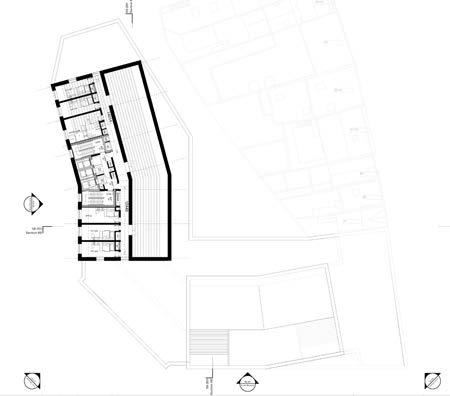
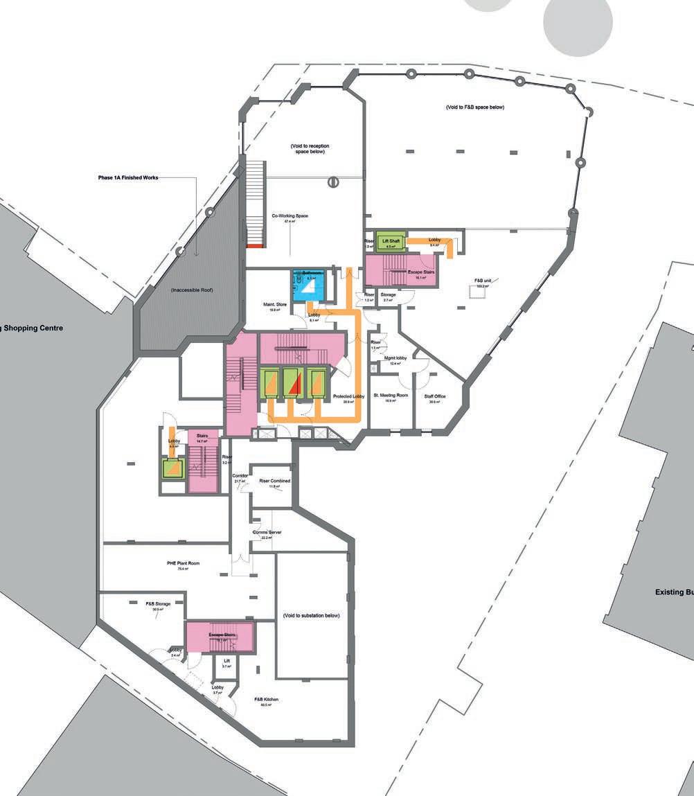
Fig.5 N1, Proposed Mezzanine
4.6 Horizontal circulation
Horizontal circulation on each floor is level with no level changes with the exception of the ground floor, as mentioned above.
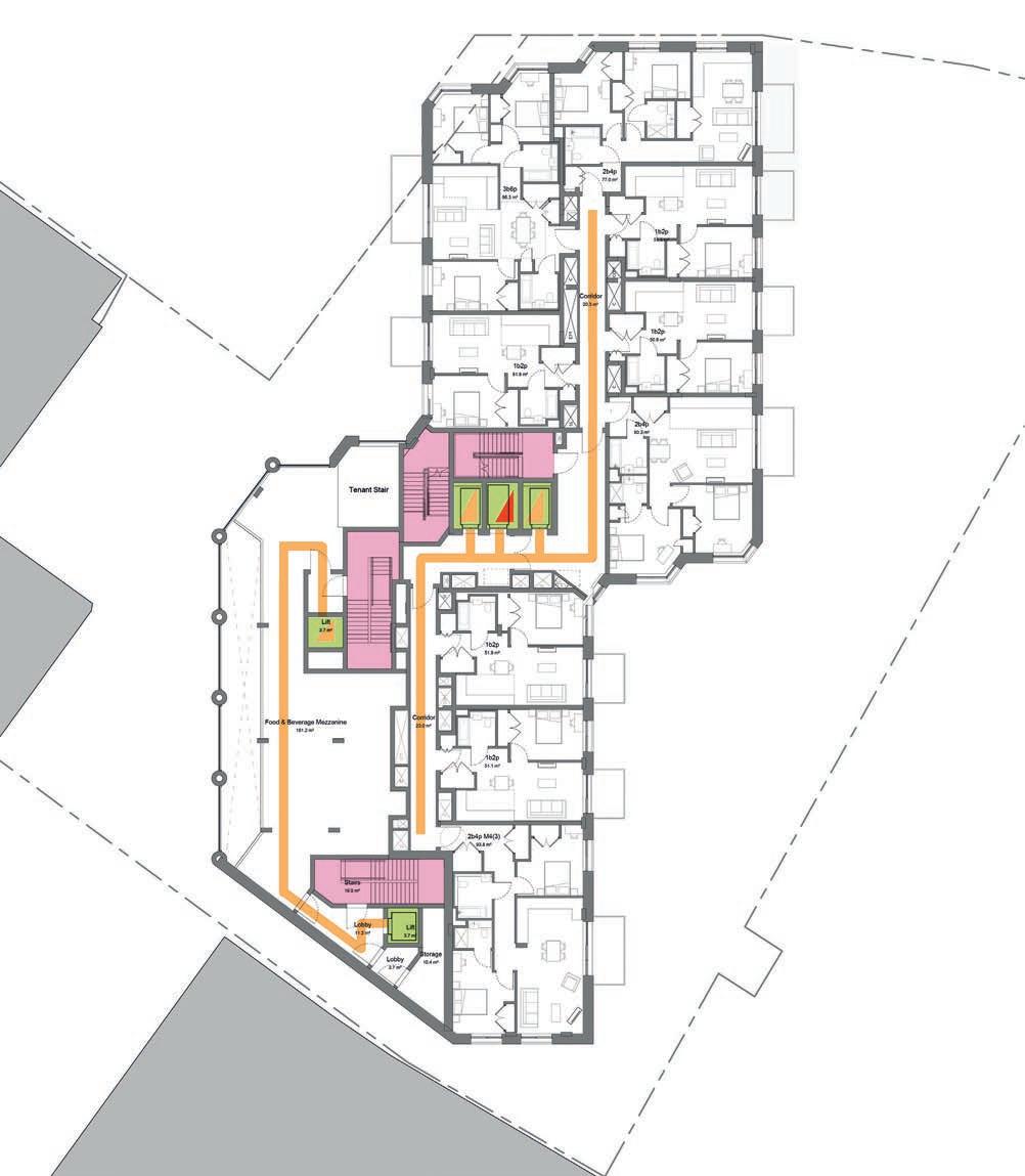
The typical accommodation floor plan (levels 02 to 08) is organised around a central corridor that gives access to all private units and connects the northern core with the southern core.
The central corridor is proposed 1500mm wide as per the Housing Design Standards LPG, with sections 1800mm wide where more people flow is expected: in front of both cores and at the central section of the corridor where the building turns and a communal lounge area is proposed. The lounge are will provide a break of the corridor to assist in navigating the space, and its window will provide natural daylight into the corridor.
Levels 09 to 20 follow the same accommodation with the floorplan reduced due to the building setbacks. On level 01, where all communal amenities are located, the same strategy for corridor width has been followed.
Consideration will be given to materials and finishes at the appropriate stage of design development in order to avoid the use of visually and acoustically reflective surfaces and the use of bold patterns that could create visual confusion or be mistaken for changes in level.
All internal doors will be designed to meet the guidance of AD M Vol.2 and will have a minimum
clear opening width of at least 800/825 mm depending on the approach, through a single leaf door, or one leaf of a double leaf door, unless power operated or held open. All internal doors will have an unobstructed space of at least 300 mm on the pull side of the door between the leading edge of the door and any return wall.
Further details such as vision panels, ironmongery and opening force, will be subject to detailed design and are expected to comply with AD M Vol.2 and follow the guidance from BS8300-2:2018 where practicable.
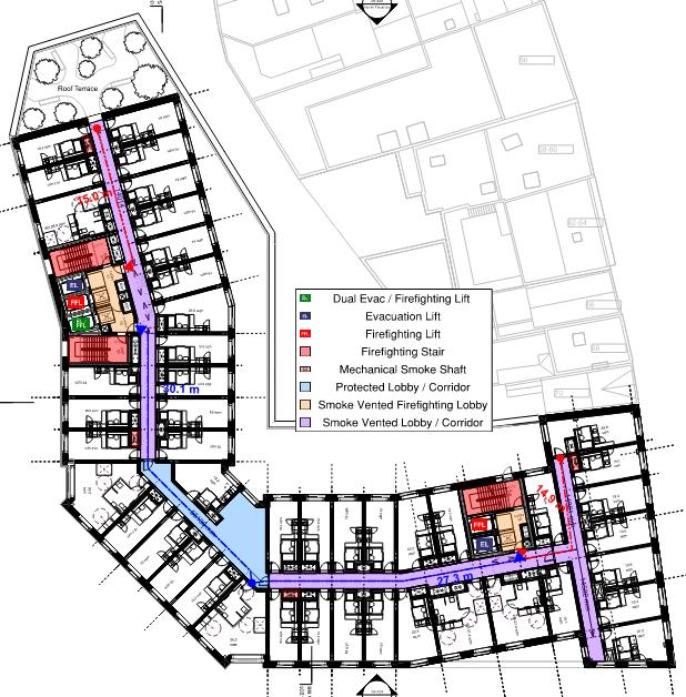
4.7 Vertical circulation
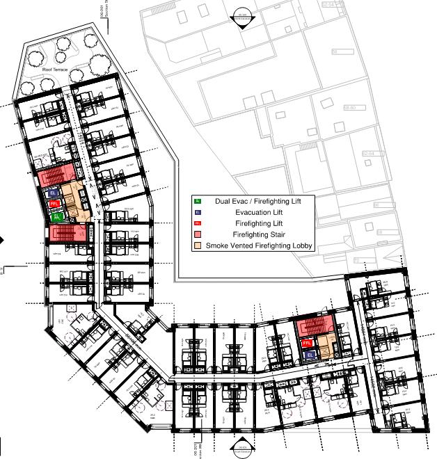
The northern core is comprised of three passenger lifts that provides access to all floors from ground floor to level 10, and two staircases. The southern core is comprised of two passenger lifts that provides access from ground floor to level 08, where the building stops on this side, and a staircase. Each core includes a fire-fighting lift and one/two evacuation lifts.
All proposed lifts have dimensions that exceed the minimum dimensions required by AD M Vol. 2 of 1100 mm wide by 1400 mm deep, so that can accommodate a wheelchair user and several other persons. All passenger lifts have a level landing of at least 1500x1500 mm in front of the lift doors. Details of the lifts will be developed at a later stage and are expected to follow the statutory guidance from AD M Vol. 2 and BS EN 81-70.
All stairs (except those solely serving plant areas) have been designed to meet the requirements of Part K for ‘general access stair’. Details of the stairs will be developed at a subsequent stage of design development, and are expected to meet the guidance of AD K and consider the good practice guidance from BS8300-2.
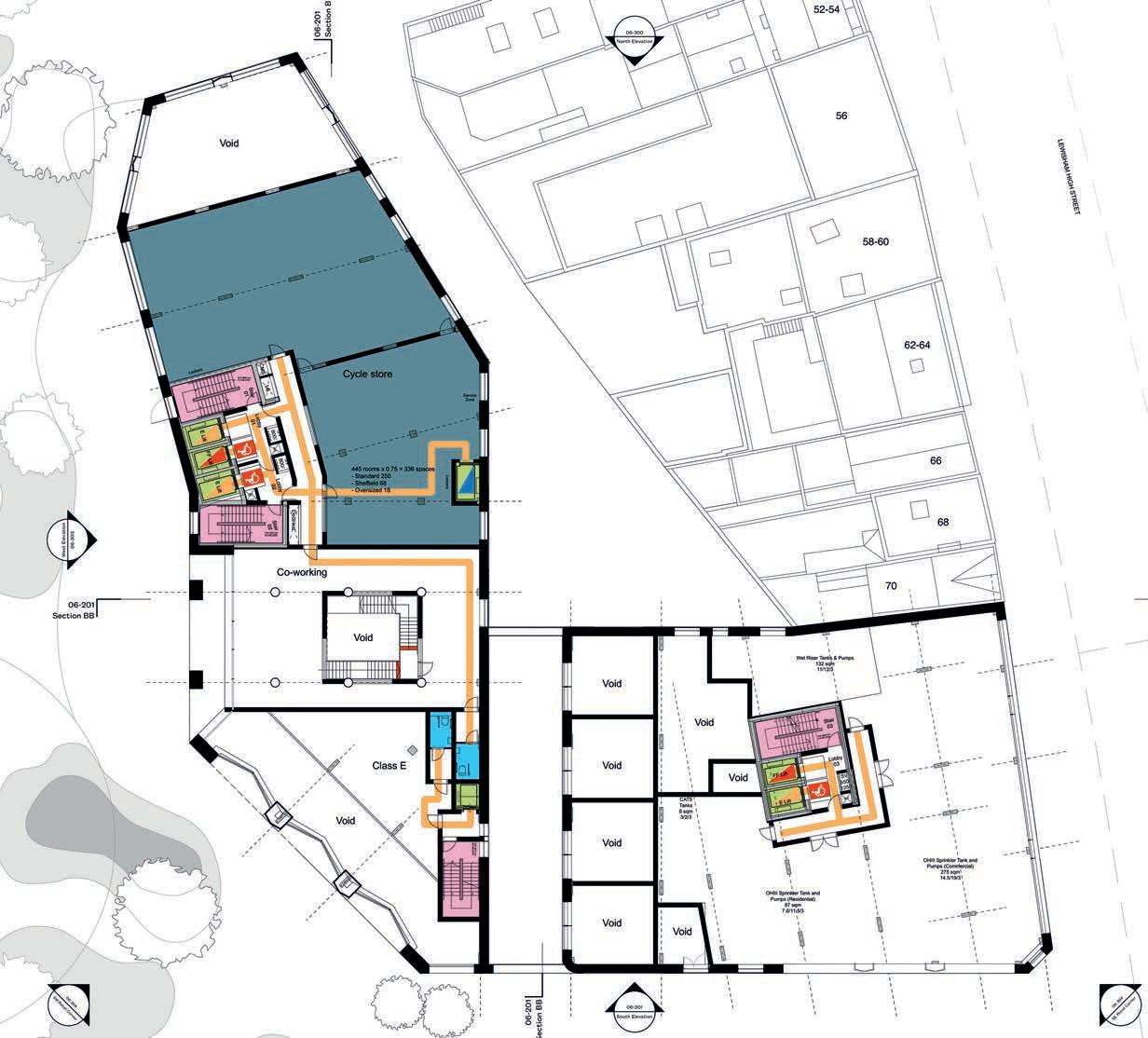
4.8 Communal facilities
Communal facilities have been provided as follows:
• Reception area at ground floor;
• Co-working at mezzanine level;
• Gym, lounge, cinema room, games rooms and laundry at level 01;and
• A shared cooking/dining rooms, lounge, private dining and game room on level 08.
Additionally, communal outdoor spaces are provided on level 02 and 08.
All communal facilities have been designed with regard to the requirements of all users, visitors, and staff, and to be as inclusive and convenient to all as possible, and follow the guidance from LSPBSL LPG.
A variety of sizes of amenity rooms with different finishes (materials, lighting, etc) will be provided for the benefit of people who experience sensory differences.
Sufficient manoeuvring space has been provided within all communal facilities to allow wheelchair users and people with mobility impairments to move conveniently within spaces.
All the kitchens will be designed to achieve the level of access required for wheelchair users by BS8300: 2009 12.1 and Approved Document M 4.13-4.16 (shared refreshment facilities).
Terraces will be further developed at the next stage of design development, including accessible terrace doors, thresholds, access route widths, and surfaces. The good practice guidance of BS 83001:2018, including provision of a variety of seating both fixed and movable, will be considered. Terrace fit-out will consider circulation and manoeuvring spaces.
The Screen room will include a permanent wheelchair space at the front row, and the potential to provide further wheelchair spaces by removing the furniture, which is intended to be loose furniture.
4.9 Sanitary provision
Sanitary provision has been provided in all floors where communal amenities are provided. On each sanitary accommodation core a unisex AWC has been included, and there will be a WC cubicle for use by ambulant disabled people.
Consideration has been made to provide choice of right and left-hand side transfer to the AWC at
alternate floors. AWC compartments will be designed in accordance with AD M Vol.2 and the best practice guidance in BS8300. Details will be subject to detailed design and developed at a later stage.
4.10 Refuse stores
The refuse store is located at ground floor accessed off the northern lift core. To allow level access from the service road into the refuse store, the store is 380mm lower than the internal ground floor level. A ramp has been proposed to provide internal stepfree access from the lift core to the refuse store for residents.
4.11 Signage
A consistent signage and wayfinding strategy will be developed at the relevant stage of design development. Good practice guidance, such as BS 8300:2018 and Sign Design Guide, will be considered.
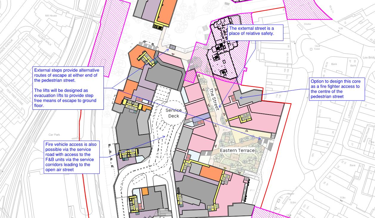
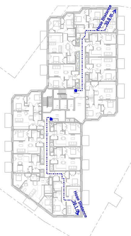
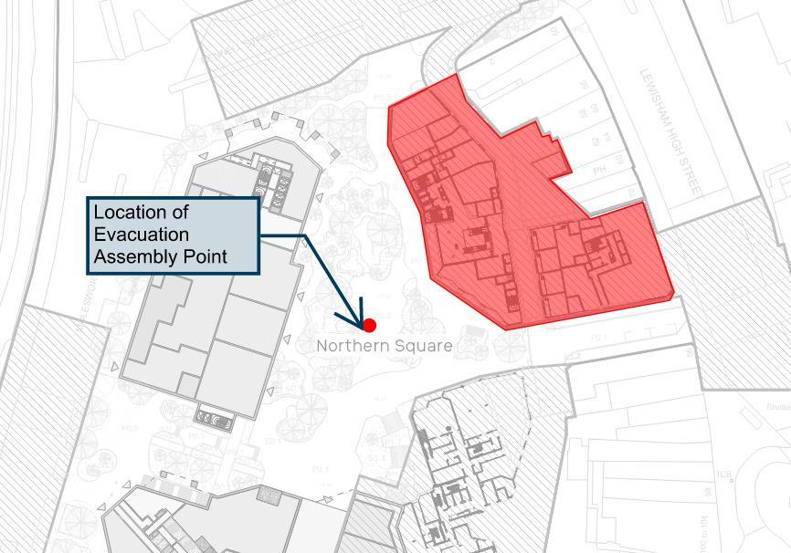
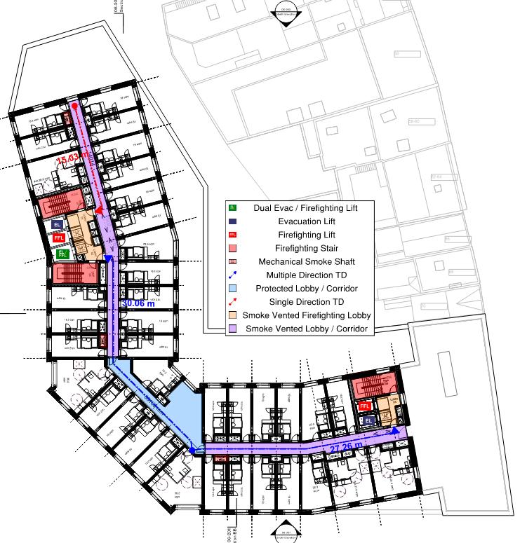
4.12 Emergency escape
Suitable means of escape provisions will be provided for all building occupiers including disabled people. In line with the London Plan 2021, evacuation lifts have been provided in both cores that will provide a safe and dignified means of escape for all building occupiers. Additionally, a safe space for someone
to wait for an evacuation lift is provide on each protected lift lobby.
Please refer to the Fire Safety Statement by Jensen Hughes for further information.
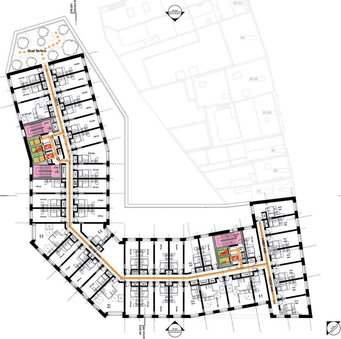
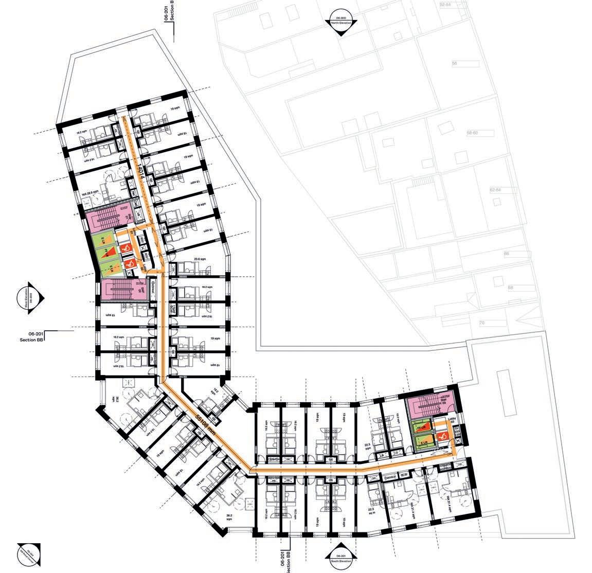
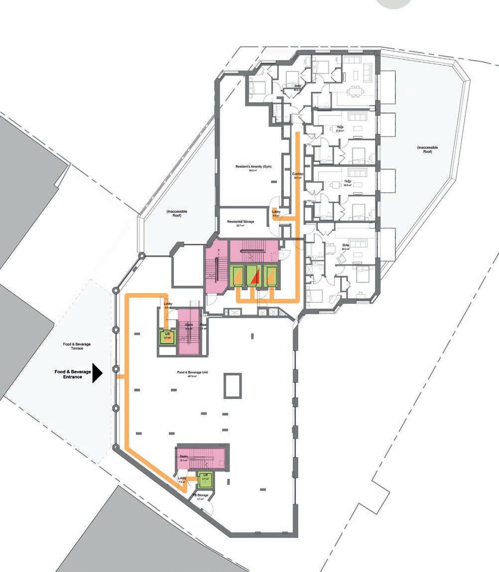
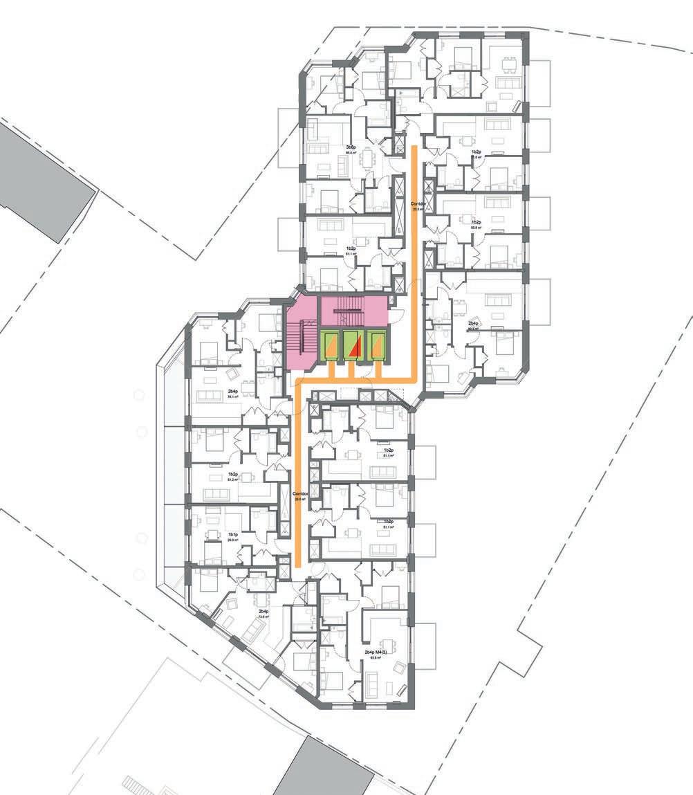
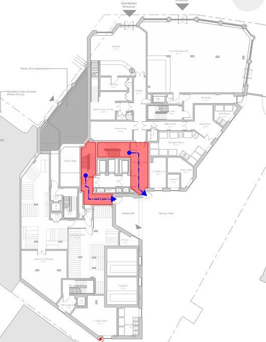
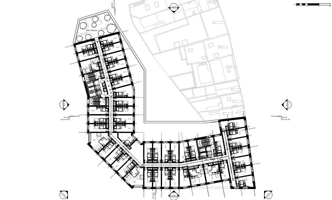
Fig.6 N1, Proposed Level 01
Fig.7 N1, Proposed Level 02
Fig.8 N1, Proposed Level 03-07
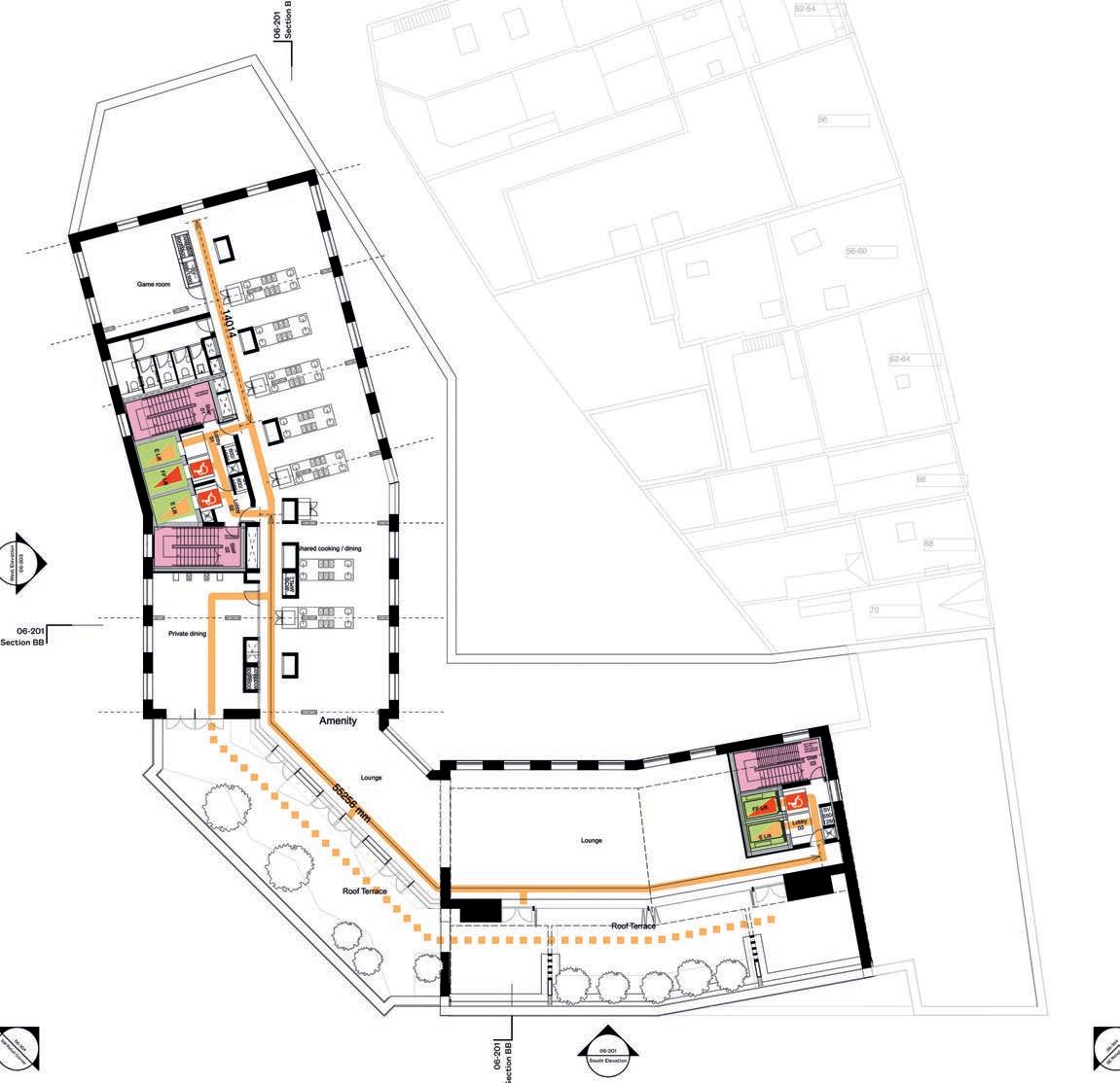
Fig.9 N1, Proposed Level 08
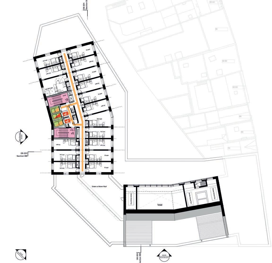
Fig.10 N1, Proposed Level 09
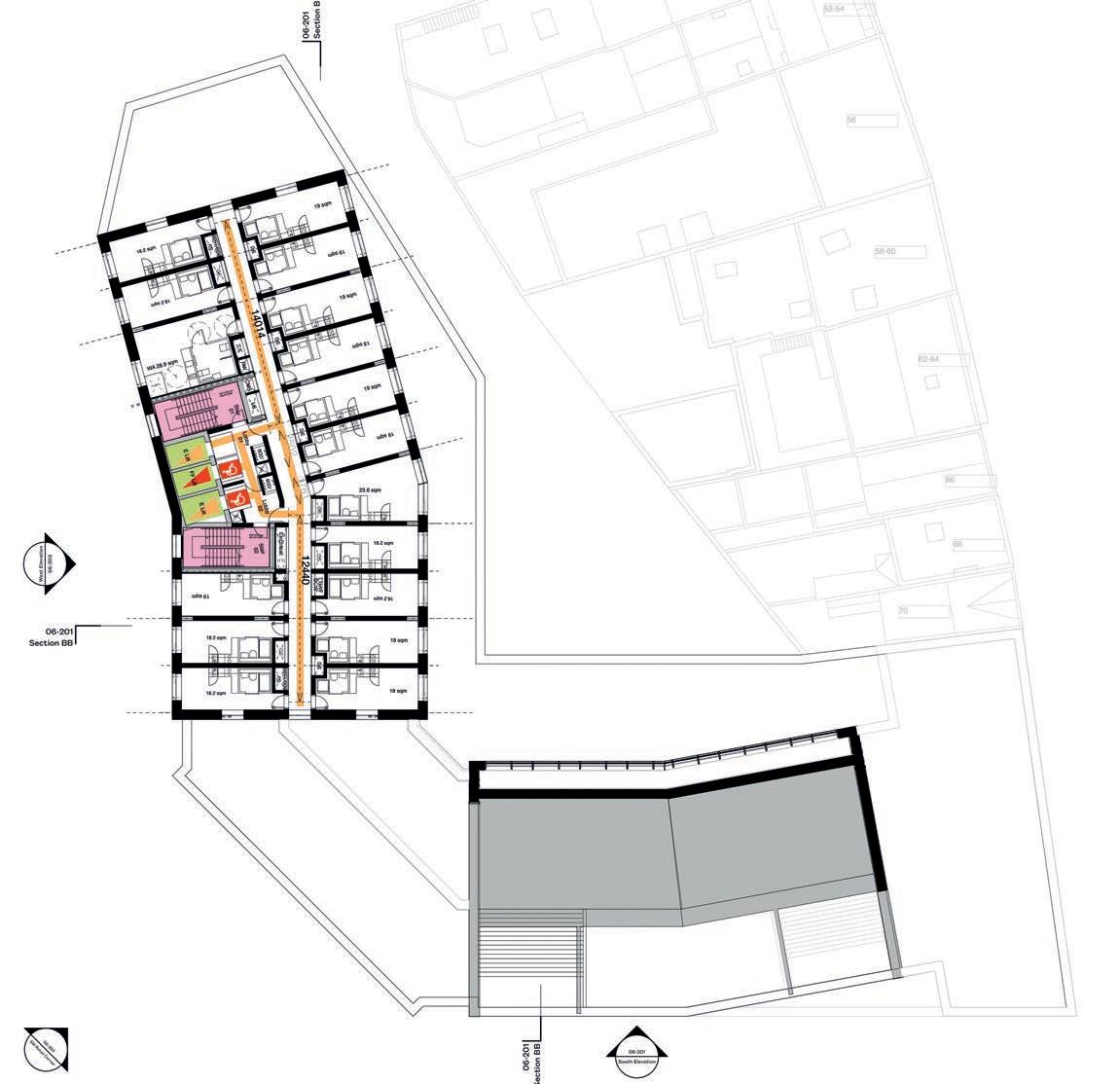
Fig.11 N1, Proposed Level 10-19
4.13
Wheelchair-Accessible units
The Proposed Development will provide 445 private units distributed from level 02 to 20, which 10% (46no. units) will be accessible units.
The accessible provision have been distributed as far as possible to provide a variety of locations and easy access from the lift core.
All private units will have step-free access from the lift core and will be accessible for other residents and disabled visitors. Visitors to the private units will have access to the accessible WCs located at ground, mezzanine, level 01 and 08, where communal amenities are provided.
All units will be designed to meet the guidance of AD M Vol.2 provisions 4.24 (a-f) for sleeping accommodation, including the provision of visual (and audible) fire alarm signals, wardrobe swing doors that open 180º, and controls for openable windows to be located 800-1000mm AFFL and be easily operable one-handed. Height, positioning, type, and tonal contrast of switches and sockets within all bedrooms will be designed to AD M Vol.2. Taps in all bedrooms will be easily operable onehanded using a closed fist.
Fig.12 Location of accessible units
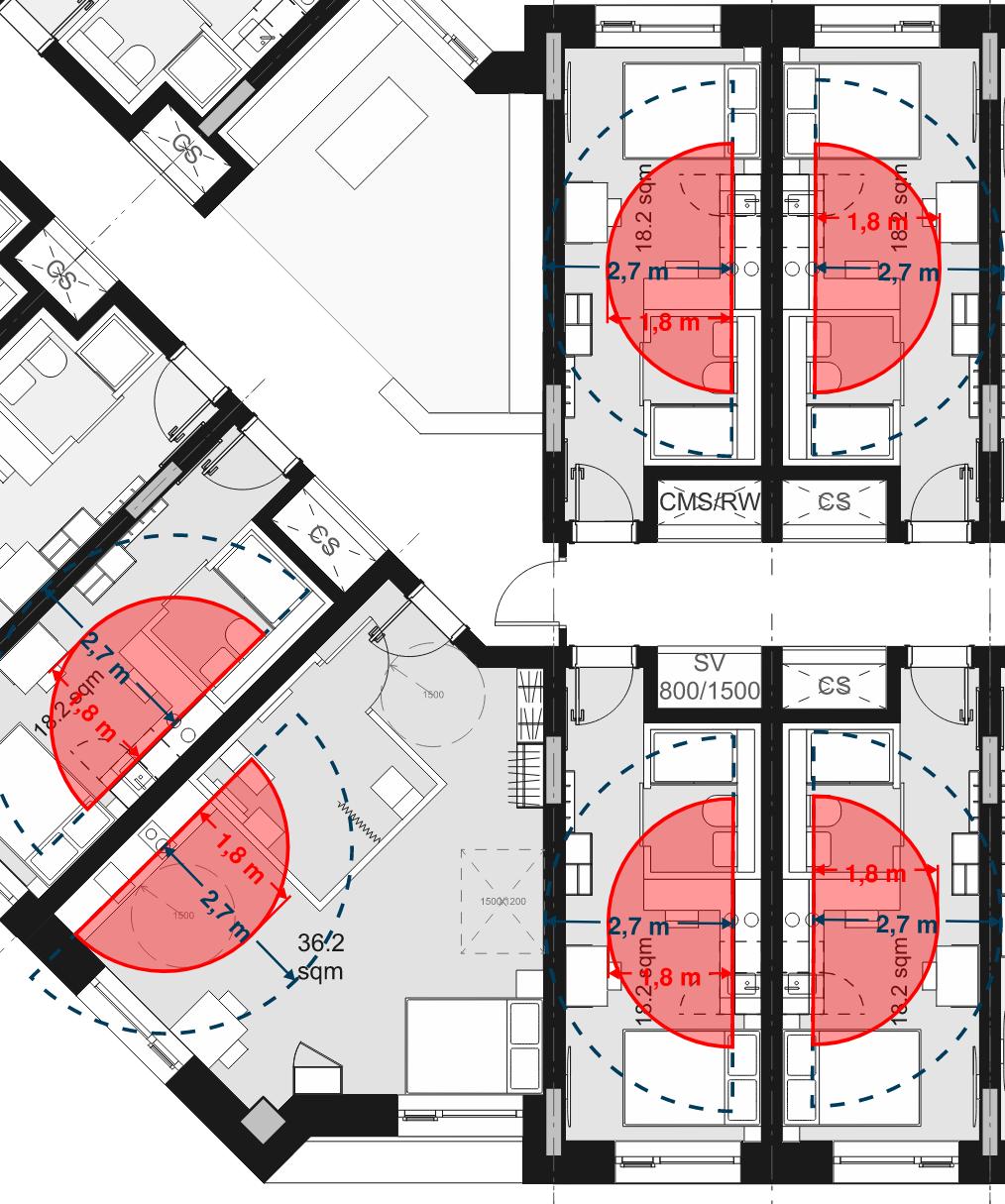
4.14
Wheelchair-Accessible unit layouts
The following features are the minimum access provisions required by Building Regulations requirement M1 for sleeping accommodation, which the proposed rooms have been designed to. Further design development will ensure full compliance with these standards:
1. Entrance doors - have a minimum clear opening width of 800mm and 300 mm nib on the leading edge.
2. Internal circulation - bedrooms allow wheelchair users to manoeuvre around and use the facilities in the room.
3. Internal doors - have a clear opening width of 800/825mm with a 300mm nib on the leading edge
4. Bed - bedrooms allow for a wheelchair user to manoeuvre at the side of a bed, then transfer independently to it.
5. Sanitary facilities - bedrooms have an en-suite wheelchair-accessible shower room.
6. Kitchenette - at least a part of the working surface - that includes a sink and a hob - is at 850mm above the floor with a clear space beneath at least 700mm above the floor.
7. Additionally, the accessible rooms will provide a wheelchair storage and transfer space - where a wheelchair user could change from an outdoor wheelchair to an indoor wheelchair if preferred.
4. Detailed element - Phase 1a Plot N2, Residential
5. Detailed element - Phase 1a, Plot N2
Plot N2 is part of Phase 1a and sits on the north-east of the site, to the west of the existing buildings facing Lewisham High Street. To the north, Plot N2 faces Plot N1, and a public route between both buildings provides permeability to the site through a new east -west connection.
5.1 Approach to the building
Main pedestrian route to the building entrance is from the Northern Square along a level route, from the north of the site or from the service road to the east.
The Northern Square is a pedestrian only route with suitable ground surface and seating and planting. The service road have unobstructed, 1800mm-wide pavements on both sides of the vehicular route. Pedestrians will be separated from the carriageway with 60mm high kerbs with crossing that include tactile paving and dropped kerbs.
5.2 Car parking and Drop-off point
Plot N2 will be car-free with the exception of the provision of 3 Blue Badge bays (BB) located at the rear of the building. Vehicular access to these bays is through the service road. A safe pedestrian route, will be provided from the BB bay to the rear entrance of the building.
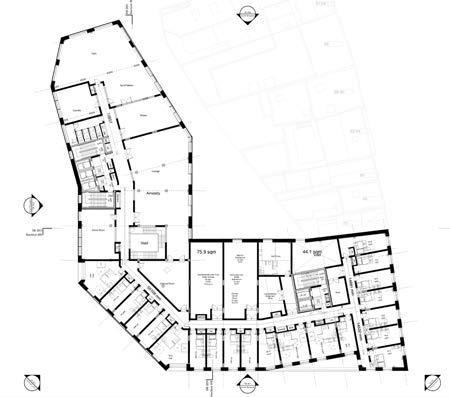
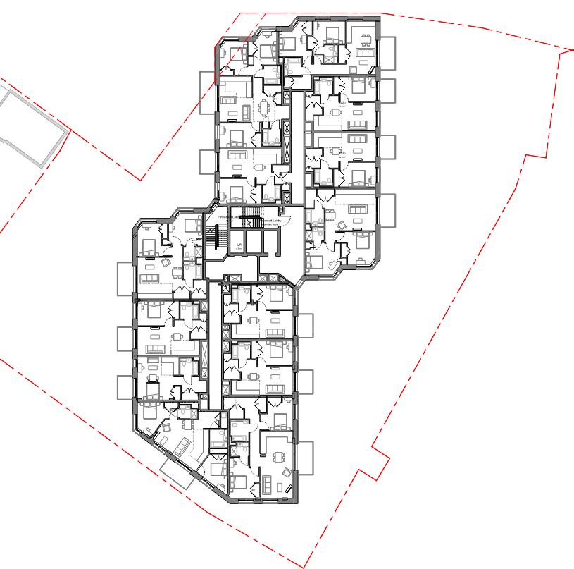
Fig.13 N2, Proposed Ground floor
A secondary entrance from the rear of the building has been proposed to provide direct access from the BB bays into the building. The rear entrance into the building has been recessed to provide a landing before the pedestrian crossing where people can assess whether is safe to cross or not.
People who rely on community transport, taxis or minicabs as a mean of transport to the site, will be able to be dropped-off/picked-up on the service road at the north of the site at c.45m from the main entrance to the building. Routes are level and with suitable width and ground surfaces.
5.3 Cycle parking
A secured and covered cycle store is provided at ground floor accessed from the main foyer or from the rear entrance to the building.
The proposed cycle parking provision will be in line with the London Plan with layouts designed in line with the London Cycling Design Standards (LCDS), including cycle parking spaces that can accommodate larger cycles, including adapted cycles for disabled people as follows:
• 5% of the total cycle spaces will be larger spaces;
• 20% of the total cycle spaces will be Sheffield stand types; and
• 75% of the total cycle spaces will be double stack stands.
From the cycle stores, residents can access the their dwellings via the lift core located in close proximity.
5.4 Entrances
Main entrance to Plot N1 is from the Northern Square via a recessed double-leaf swing door that makes the entrance readily apparent.
The entrance has a lobby with sufficient length to allow wheelchair users with a companion to move safely from one door to the other. The entrance lobby will have floor surfaces that do no impede the movement of wheelchair users and remove rainwater from shoes and wheelchairs to avoid potential slip hazards.
The F&B retail units on the ground floor have independent access from the street. Entrances will be covered if doors are manual.
Residential communal entrance will be designed in accordance with provisions in paragraph 3.14 of AD M Vol.1 including a level landing of at least 1500 mm by 1500 mm in front of the entrances outside, weather protection of at least 1200 mm depth, and provision of a 1500 mm turning circle inside the entrance area. All entrance doors will provide a clear opening width of at least 850 mm through one leaf in double-leaf doors, and a 300 mm nib on the leading of doors and a 200 mm nib on the following edge of doors.
Non-residential entrance doors will have a minimum 1000mm clear opening width through one leaf in double-leaf doors.
All thresholds to both, residential and non-residential entrances, are proposed accessible with details to be developed at a later stage.
Details of lighting, door opening force, floor surface and door entry controls will be developed at the next design stage following the guidance from AD M.
The residential entrance leads to lobbies from where residents and visitors can access the lift and stair.
Details of the reception area will be developed at subsequent stages of design. These areas will be designed to meet AD M Vol.2 and best practice recommendations from BS8300-2 and PAS 6463 where appropriate, including, but not limited to, the provision of fixed hearing enhancement system(s) at reception and service desks and lower sections of desk / counter that are permanently accessible to wheelchair users.
5.5 Horizontal circulation
Horizontal circulation on each floor is level with no level changes. The typical accommodation floor plan (levels 02 to 08) is organised around a central core that contains the lifts and stairs, and from which a central corridor to the north and to the south provides access to all dwellings. The central corridor is proposed 1500mm wide as per the Housing Design Standards LPG allowing sufficient space for wheelchair users to easily manoeuvre, and to pass in opposite directions.
Consideration will be given to materials and finishes at the appropriate stage of design development in order to avoid the use of visually and acoustically reflective surfaces and the use of bold patterns that could create visual confusion or be mistaken for changes in level.
Cross-corridors doors have been minimised and located only where necessary for fire protection reasons. All doors in communal routes have a clear opening width of 850 mm through a single leaf door, or one leaf of a double leaf door; and a 300 mm clear space to the leading edge on the pull side of the doors and 200 mm clear space in the push side.
Details of lighting, door opening force and finishes will be developed at the next design stage following the guidance from paragraph 3.9 of AD M Vol.1.
5.6 Vertical circulation
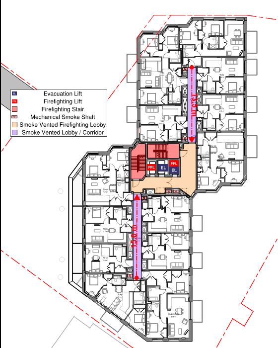
The central core is comprised of three passenger lifts and two staircases. One of the lifts is a fire fighting lift and the other two are evacuation lifts.
All lifts will be be designed in accordance with the provisions in paragraph 3.16 of AD M Vol.1. Proposed car lifts exceed the minimum required dimensions of 1100 mm wide by 1400 mm deep, and there is a landing of at least 1500 mm by 1500 mm in front of all lift entrances that is clear of door swings.
Details of landing and car controls, and ensuring compliance with the requirements of BS EN
81-70:2003 will be developed at the next design stage following the guidance in paragraph 3.16 of AD M Vol.1.
All stairs are to be designed in accordance with the provisions in paragraph 3.17 of AD M Vol.1 and the requirements of Part K for ‘general access stair’.
5.7 Refuse stores
A refuse store is located at ground floor with internal access from the lift lobby. The routes from the dwellings to the refuse store will be step-free and will be accessible to all residents including wheelchair users. The horizontal distance between any dwelling and its refuse collection point will be less than thirty metres to ensure compliance with Part H of the Building Regulations.
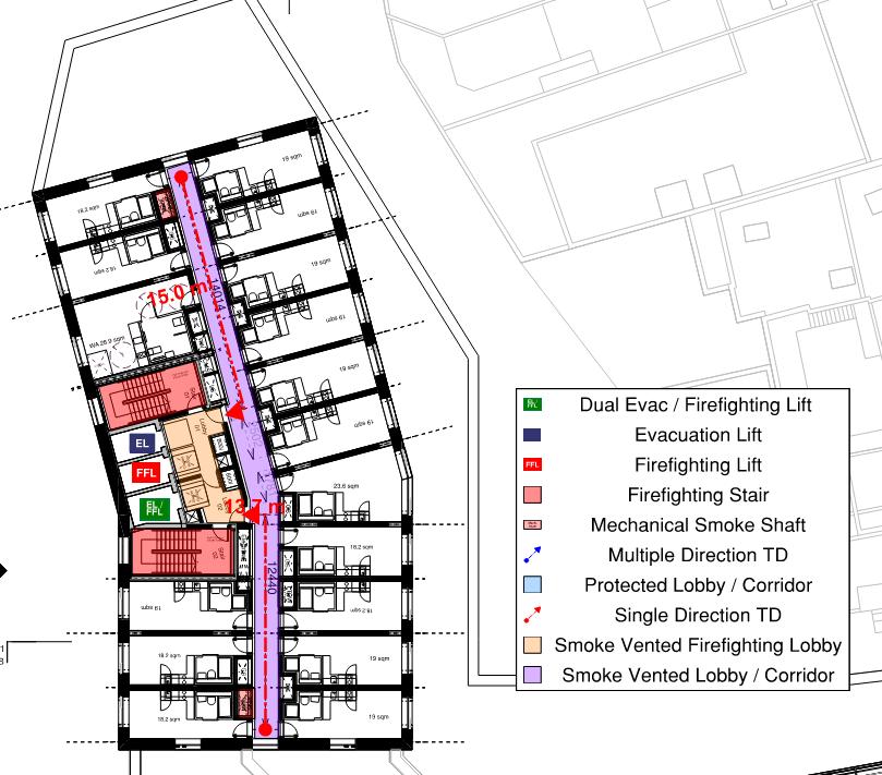
5.8 Emergency egress
Suitable means of escape provisions are provided for all residents including disabled people.
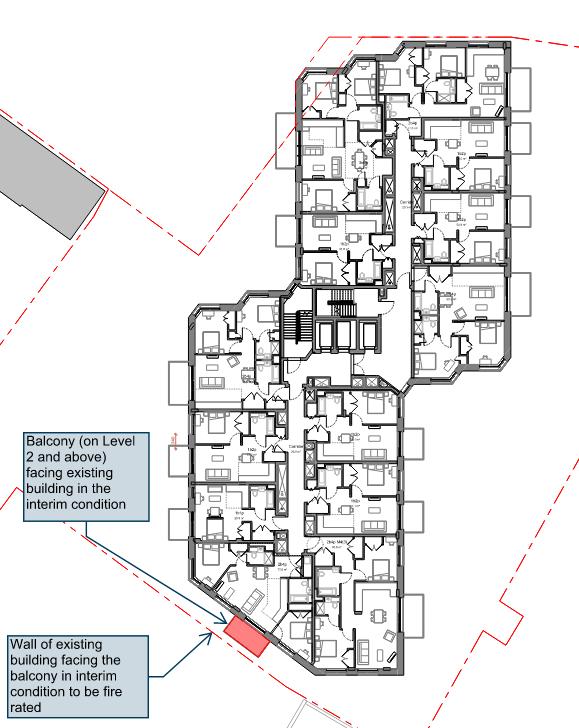
Normal provisions for residential buildings will apply to the development whereby only the residents of an affected unit will evacuate. Other units and their residents are protected as the dwellings themselves function as safe refuges.
In line with the London Plan 2021 Policy D5 (B5) evacuation lifts in separate fire-protected cores are proposed.
Please refer to the Fire Safety Statement by Jensen Hughes for further information..
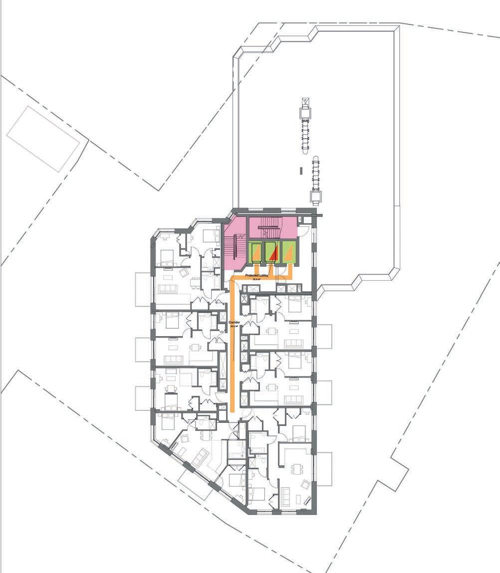
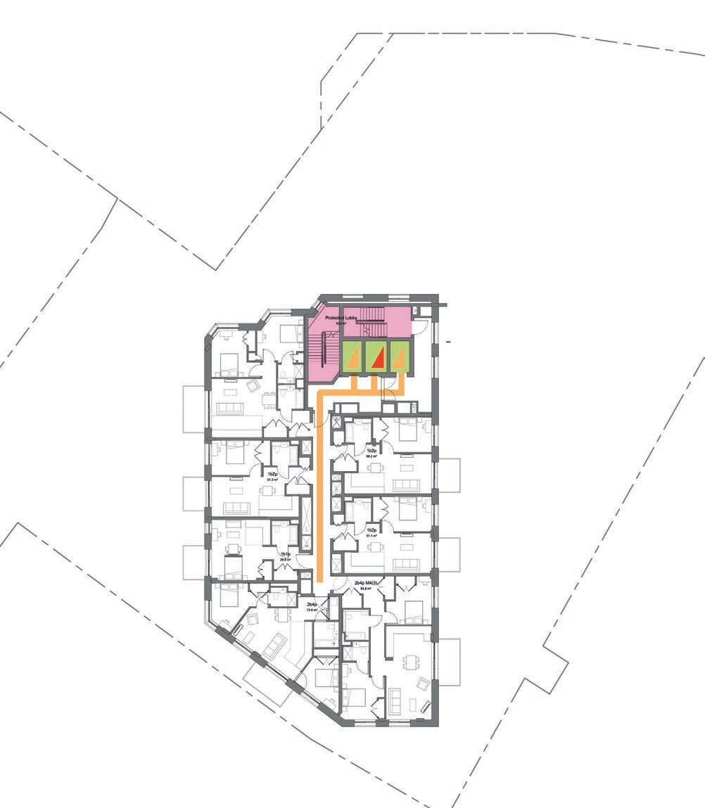
Fig.14 N2, Proposed Ground floor Mezzanine
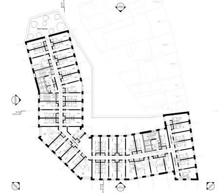
Fig.15 N2, Proposed First floor
Fig.16 N2, Proposed First floor Mezzanine
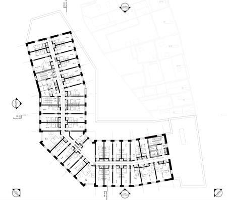
Fig.17 N2, Proposed Second floor
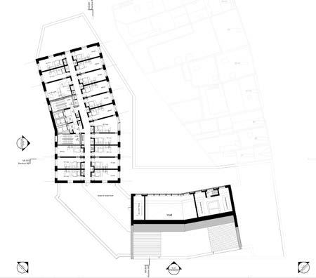
Fig.18 N2, Proposed Eight floor
Fig.19 N2, Proposed Tenth floor
5.9
Accessible Housing
Plot N2 will provide 119 dwellings distributed across 8 floors.
In line with the London Plan 2021, at least ten per cent of the dwellings will be designed to meet Building Regulation requirement M4(3) ‘wheelchair user dwellings’, and the rest will be designed to meet Building Regulation requirement M4(2) ‘accessible and adaptable dwellings’.
Wheelchair user dwellings have been distributed throughout the development, across type, size and level, as far as possible to ensure that:
• Wheelchair user units are not clustered together; and
• Wheelchair users have as much choice about the location and level of their home as anybody else, as far as possible.
The provision made to meet Building Regulation requirement M4(3) can be of two types:
• Wheelchair adaptable dwellings: the access provisions allow a simple adaptation of the dwelling to meet the requirements of occupants who use wheelchairs.
• Wheelchair accessible dwellings: the access provisions meet the requirements of occupants who use wheelchairs.
Wheelchair adaptable dwellings are intended to be capable of becoming wheelchair accessible through easy adaptations that do not require structural or service modifications, or moving walls. They have greater flexibility in their internal layout, such as bathroom or kitchen layouts.
Wheelchair accessible dwellings are intended to be readily usable by wheelchair users at the point of completion.
Wheelchair user dwellings will normally be designed as wheelchair accessible only where the local authority is responsible for allocating or nominating a person to live in that dwelling.
The proposed overall distribution is as follows:
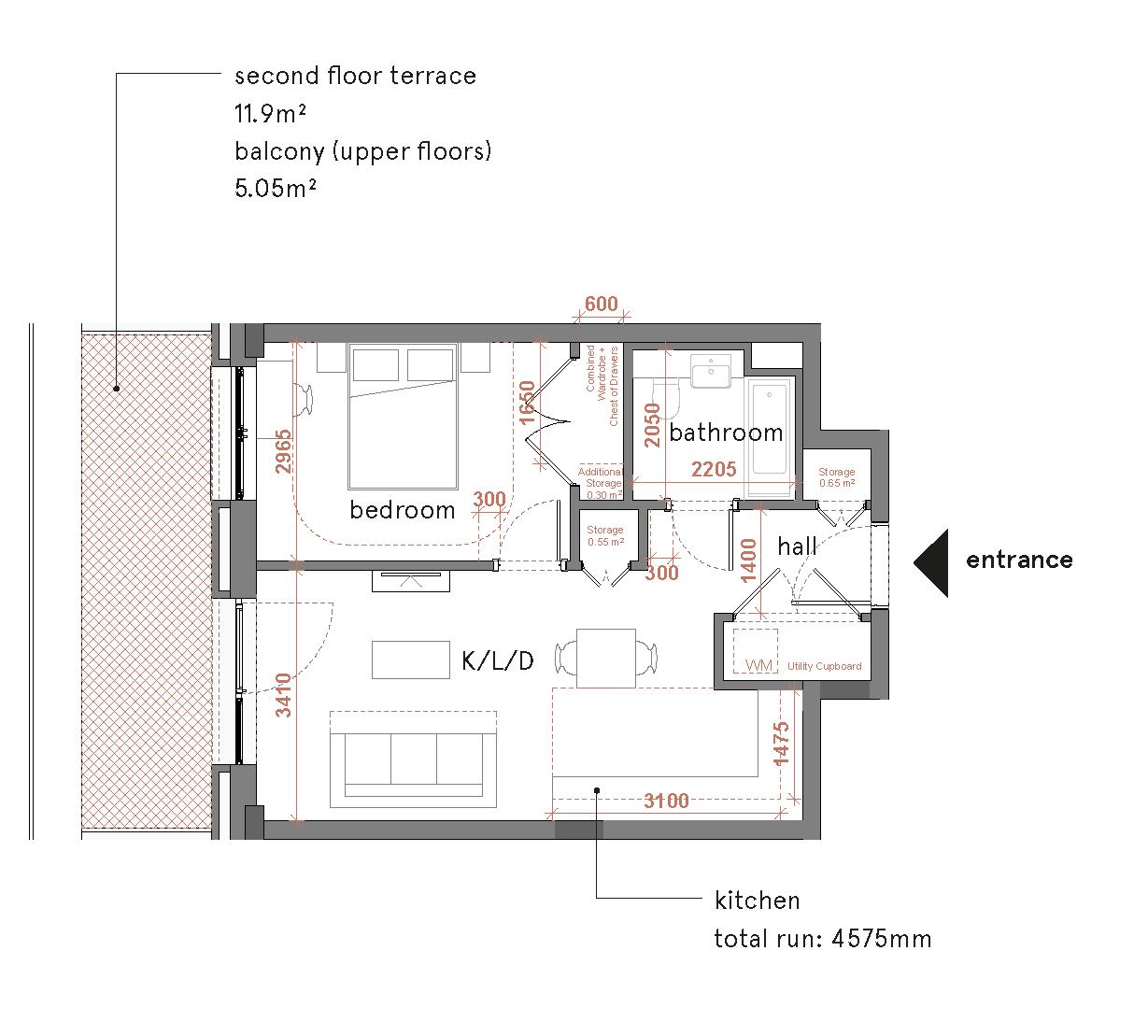
5.10
Typical M4(2) dwellings
The following features are the minimum access provisions required by Building Regulations requirement M4(2) ‘accessible and adaptable dwellings’, which the proposed dwellings have been designed. Further design development will ensure full compliance with these standards.
1. Private entrances - are covered as all dwellings are accessed from internal corridors, and have a level landing of minimum 1200x1200mm in front of entrance doors. Lighting is not yet detailed but is expected to be provided.
2. Private entrance doors - have a minimum clear opening width of 850mm, and 300 mm nib on the leading edge maintained 1200 mm beyond the door, and are not recessed by more than 200mm. All thresholds are accessible.
3. Doors to balconies - have a minimum clear opening width of 850mm, and 300 mm nib on the leading edge maintained 1200 mm beyond the door. Where sliding doors to the balcony are provided, a 300mm nib is provided on both sides. Doors are not recessed by more than 200mm and all thresholds are accessible.
4. Corridors - are generally 1050mm wide, and not less than 900mm wide in any case.
5. Internal doors - have a clear opening width of 750/775/800mm depending on their approach, with a 300mm nib on the leading edge.
6. Kitchens - have a 1200mm clear space in front of all kitchen units. Washing machine are located outside the kitchen area within the utility cupboard. A 1200mm clear space is provided in front of the washing machine.
7. Bedrooms - have a clear access route of 750mm from the doorway to the window. Main double bedrooms have a clear access zone of 750mm on both sides and the foot of the bed. Other double bedrooms have a clear access zone of 750mm on one side and the foot of the bed. Single bedrooms have a clear access zone of 750mm on one side of the bed.
8. Bathrooms - all dwellings have a bathroom that contains a WC, a basin and a potential level access shower that meet the provisions of Diagram 2.5 of AD M Vol.1. Doors to these bathrooms open outwards. Details of the potential level access shower will de developed at a later stage.
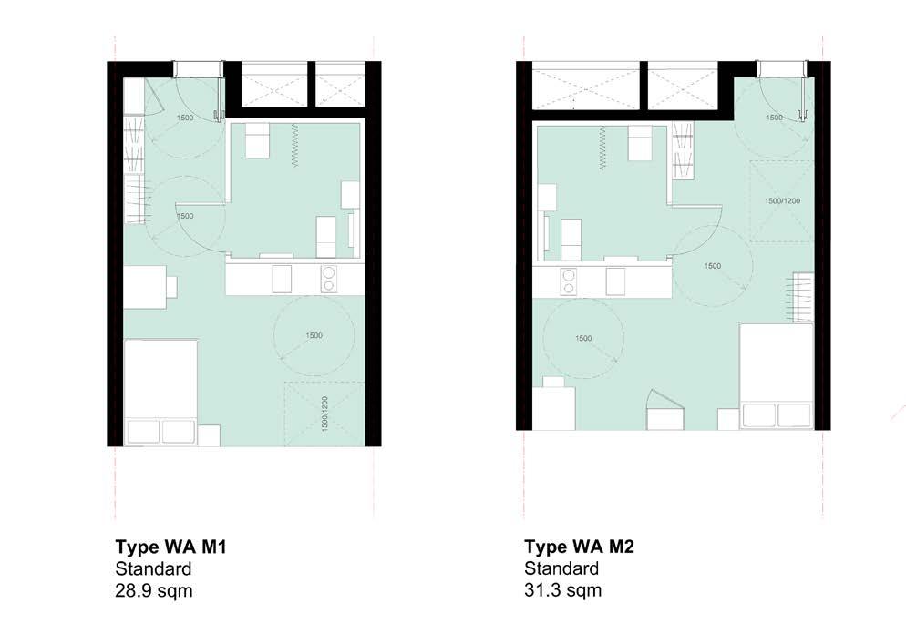
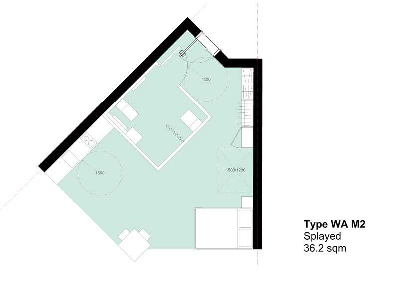
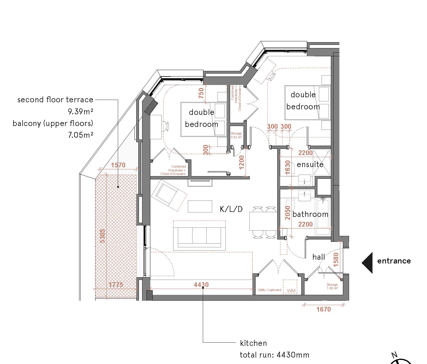
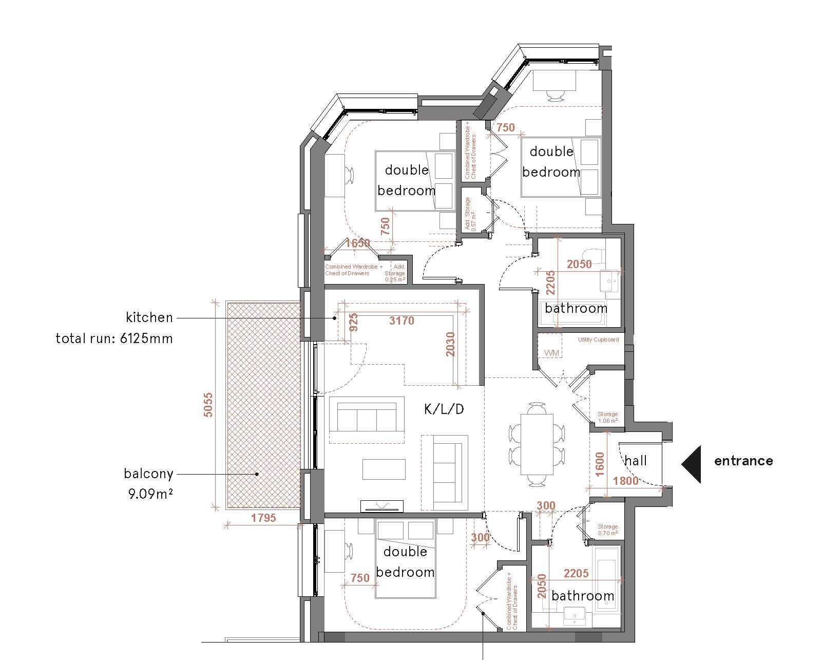
Fig.20 Typical 1B2P flat layout
Fig.21 Typical 2B4P flat layout
Fig.22 Typical 3B6P flat layout
5.11
Typical M4(3) dwellings
The following features are the minimum access provisions required by Building Regulations requirement M4(3) ‘wheelchair user dwellings’, which the proposed dwellings have been designed. Further design development will ensure full compliance with these standards.
1. Private entrance doors - have a minimum clear opening width of 850mm, and 300 mm nib on the leading edge maintained 1800 mm beyond the door. Entrance doors are not recessed by more than 200mm and all thresholds are accessible. A fused spur will be provided and detailed at the next design stage.
2. Doors to balconies - have a minimum clear opening width of 850mm, and 300 mm nib on the leading edge maintained 1800 mm beyond the door. Doors are not recessed by more than 200mm and all thresholds are accessible. Balconies have a minimum width of 1500mm.
3. Circulation - corridors are minimum 1050mm wide, and 1200mm where the approach to a doorway is not head-on, and internal doors have a clear opening width of 850mm, with a 300mm nib on the leading edge and a 200mm nib on the following edge.
4. Wheelchair storage and transfer space of 1100mm deep by 1700mm wide, accessed from a space 1200mm wide, located close to the entrance.
5. General built-in storage - is provided in accordance to Table 3.1 of AD M, Vol.1.
6. Living areas - All M4(3) dwellings are singlestorey and have the living area at the entrance storey. The minimum combined floor area for living, dining and kitchen space is in accordance to Table 3.2 of AD M, Vol.1.
7. Kitchens - have a 1500mm clear space in front of all kitchen units. The kitchen worktop length, including fittings and appliances, is in accordance to Table 3.3 of AD-M, Vol.1, and layouts demonstrate how the kitchen worktop can be easily enlarged to meet Table 3.4 of AD-M, Vol.1.
8. Main double bedroom - have a clear access zone of 1000mm on both sides and the foot of the bed, a clear access route of 750mm from the doorway to the window, and a clear access zone of 1000mm in front of all furniture. There is a 1200x1200mm manoeuvring space inside the doorway and on both sides of the bed. Minimum floor area of double bedrooms is 13.5m2 and have a width of at least 3m.
9. Other double bedroom have a clear access zone of 1000mm on one side and the foot of the bed, a clear access route of 750mm from the doorway to the window, and a clear access zone of 1000mm in front of all furniture. There is a 1200x1200mm manoeuvring space inside the doorway. Minimum floor area is 12.5m2 and have a width of at least 3m.
10. Bathrooms - all M4(3) dwellings have a bathroom that contains a WC, a basin and a level access shower that meet the provisions in Diagram 3.10 of AD M Vol.1, and layouts demonstrate how the bathrooms can be easily adapted in future to meet the provisions of Diagram 3.11 of AD M Vol. 1. Details of the level access shower will de developed at a later stage. Doors to these bathrooms open outwards.
11. Second WC that meet the provisions in Diagram 3.13 of AD M Vol.1.
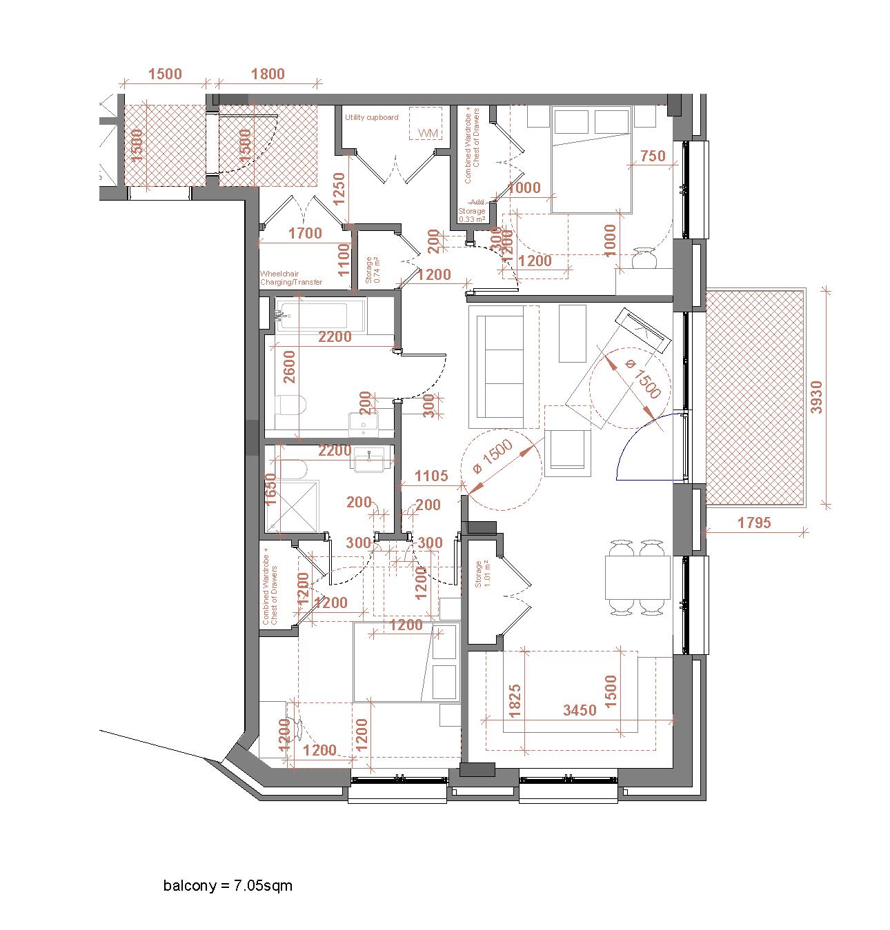
Fig.23 Typical 2B4P M4(3) flat layout
5. Appendix
Appendix 1 | References for inclusive design
Legislation
Equality Act 2010
The Equality Act 2010 (‘the Act’) combines and supersedes previous separate discrimination legislation (including the Disability Discrimination Act 1995 as amended (‘the DDA’) and the disability discrimination provisions of SENDA 2001 for England, Wales and Scotland. People are protected from discrimination and harassment based on ‘protected characteristics’; victimising anyone as a result of action taken in connection with the Act is also unlawful. There are nine different protected characteristics under the Act which have different levels of protection depending on the context (such as employment, provision of goods and services or the provision of education). This report focuses on the protected characteristic of disability; the definition of disability is essentially the same as under the DDA.
The types of discrimination that can arise in relation to disability are:
• Direct disability discrimination;
• Indirect disability discrimination;
• Treating disabled people unfavourably because of something arising in consequence of their disability without justification; and
• A failure to make reasonable adjustments for disabled people (‘the RA duty’). The RA duty works in different ways depending on who requests the reasonable adjustments to be made, for example an employee or a member of the public.
The Act also provides protection for people who are treated less favourably because of their relationship with a disabled person (such as a carer) or for people treated less favourably because they are mistakenly believed to be disabled. A disabled person can always be treated more favourably than a non-disabled person.
If an employer is a listed public authority (such as a local authority) they will be subject to the public sector equality duty. If the employer is not a public authority but carries out a public function as part of its work, it will be covered by the general part of the equality duty in relation to the exercise of that function.
The public sector equality duty seeks to promote equality from within an organisation and the general duty requires the organisation to have due regard to the need to:
• Eliminate discrimination, harassment, victimisation and any other conduct that is prohibited by the Act;
• Advance equality of opportunity between persons who share a relevant protected characteristic and those who do not; and
• Foster good relations between persons who share a protected characteristic and those who do not.
Due regard must be given to these three aims when undertaking procurement and to comply with procurement law, consideration must be given to the extent to which equality considerations are relevant and proportionate to the subject matter of the contract.
Most of the listed public authorities are also subject to the specific duty (which operates slightly differently in England and Wales). This involves reporting requirements to demonstrate compliance with the three aims of the general duty. The public sector equality duties are relevant both to the design and the management of the built environment.
The Reasonable Adjustment Duty and specific building provisions
The Equality Act does not contain any specific requirements for the built environment and therefore has no relevance to ‘compliance’ in respect of physical building standards.
Statutory Consents
When considering a reasonable adjustment to a physical feature, the Act does not override the need to obtain consents such as planning permission, building regulations approval, listed building consent, scheduled monument consent and fire regulations. If the consent is not given, there is still a duty to consider a reasonable means of avoiding the feature.
References
British Standards
• British Standard 8300:2018 Design of an accessible and inclusive built environment
Part-1: External Environment, Code of Practice
Part-2: Buildings, Code of Practice, British Standards Institution, 2018.
• BS 9999:2017 Code of practice for fire safety in the design, management and use of buildings, British Standards Institution, 2017.
• BS EN 81-28:2018, Safety rules for the construction and installation of lifts. Remote alarm on passenger and goods passenger lifts, British Standards Institution, 2018.
• BS EN 81-41:2010, Safety rules for the construction and installation of lifts. Special lifts for the transport of persons and goods. Vertical lifting platforms intended for use by persons with impaired mobility, British Standards Institution, 2010.
• BS EN 81-70:2018, Safety rules for the construction and installation of lifts. Particular applications for passenger and goods passenger lifts. Accessibility to lifts for persons including persons with disability, British Standards Institution, 2018.
• BS 5656-2:2004 Safety rules for the construction and installation of escalators and moving walks - covering disabled access, British Standards Institution, 2004.
• DD CEN/TS 15209:2008 Tactile paving surface indicators produced from concrete, clay and stone, British Standards Institution, 2008.
• BS 5395-1:2010 Stairs. Code of practice for the design of stairs with straight flights and winders,
• A Guide to Inclusive Cycling (second edition), Wheels for Wellbeing, 2019.
• Cycle Infrastructure Design: Local Transport Note 1/20, Department for Transport, 2020.
Signage, Lighting And Wayfinding
• The Colour, Light and Contrast Manual: Designing and Managing Inclusive Built Environments, Bright, K., Cook, G., Wiley-Blackwell, 2010.
• Sign Design Guide: a guide to inclusive signage, JMU and the Sign Design Guide, 2000.
Buildings
• Designing for Accessibility, CAE/RIBA Publishing, 2012.
• Inclusive Design Toolkit, Design Council, 2014.
• Building Sight: a Handbook of Building and Interior Design Solutions to Include the Needs of Visually Impaired People, Barker, Barrick and Wilson, RNIB/ HMSO, 1995.
Office And Commercial
• Workplace health, safety and welfare. Workplace (Health, Safety and Welfare) Regulations 1992. Approved Code of Practice L24, HSE Books ,1992.
• The Accessible Office: Designing the Inclusive Workplace, JMU Access Partnership, Royal National Institute of Blind People, 2005.
• Open for business: Taking the Risk out of 2004, Employers’ Forum on Disability, 2003.
LIGHTING ASSESSMENT
LEWISHAM SHOPPING CENTRE
Landsec Lewisham Limited
LEWISHAM SHOPPING CENTRE
Lighting Assessment
TYPE OF DOCUMENT (VERSION) PUBLIC
PROJECT NO. 70081637
OUR REF. NO. LSC-WSP-XX-XX-AS-SL-000001
DATE: OCTOBER 2024
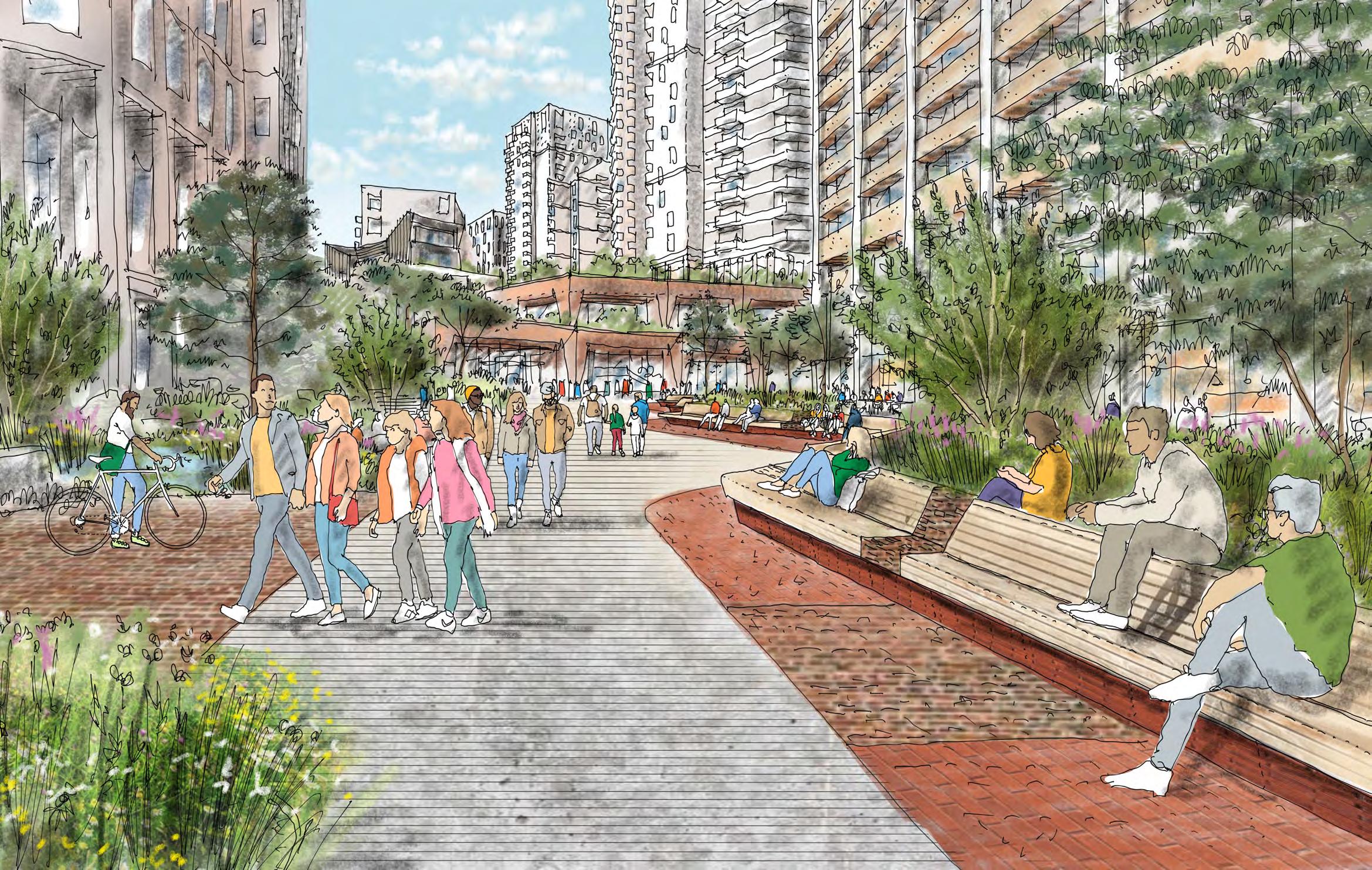
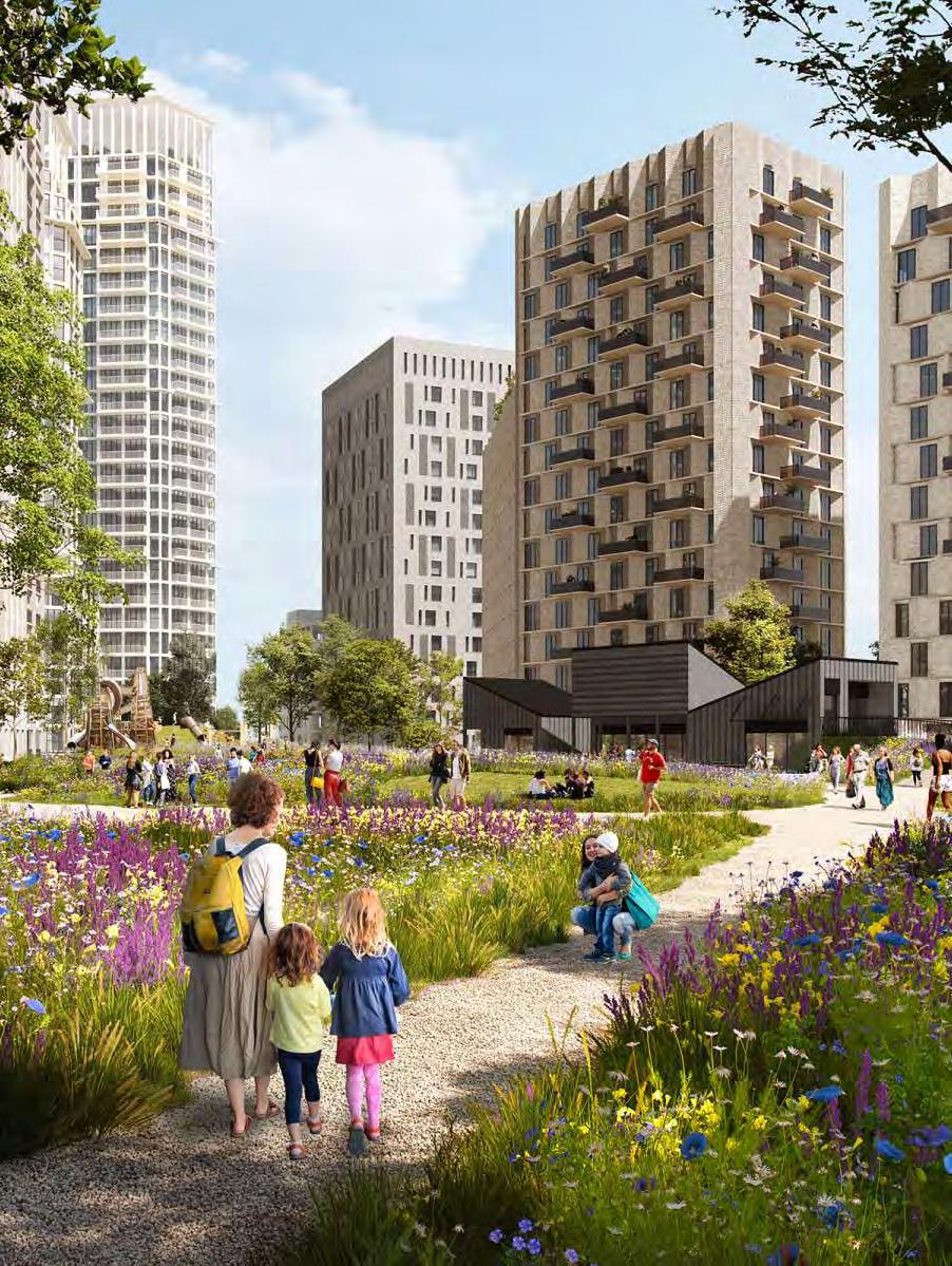
Illustrative Proposal | Provided by Studio Egret West
1. Introduction
1.1 The Site
A Hybrid Planning Application is being submitted for the Proposed Development, with Detailed Planning Permission sought for parts of Phase 1a (Plots N1, N2 and surrounding spaces), as well as shopping centre interface and highway access works; and Outline Planning Permission sought for the remainder of the scheme.
The Site currently comprises the Shopping Centre, which includes a range of retail units, a multi-storey car park, the 18-storey vacant former office building - Lewisham House, the vacant leisure box and Riverdale Hall, as well as commercial properties on the High Street.
1.2 Aim of the document
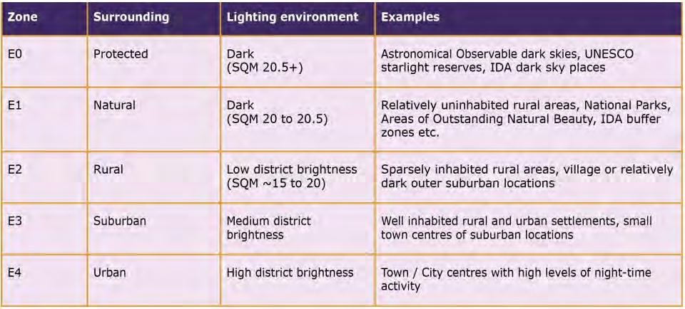
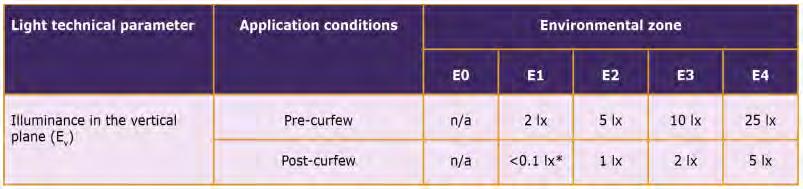
We have been appointed to provide a lighting assessment for the external illumination (only) of the proposed development which we have recommended a suitable strategy which is in keeping with the identified environmental zone.
This document outlines:
• Analysis of the lighting strategy.
• A description of the concept stage lighting control philosophy.
• Recommendations on colour temperature.
• Recommendations on optical control and the sensitivity of design in relation to the residential properties and neighbouring buildings.
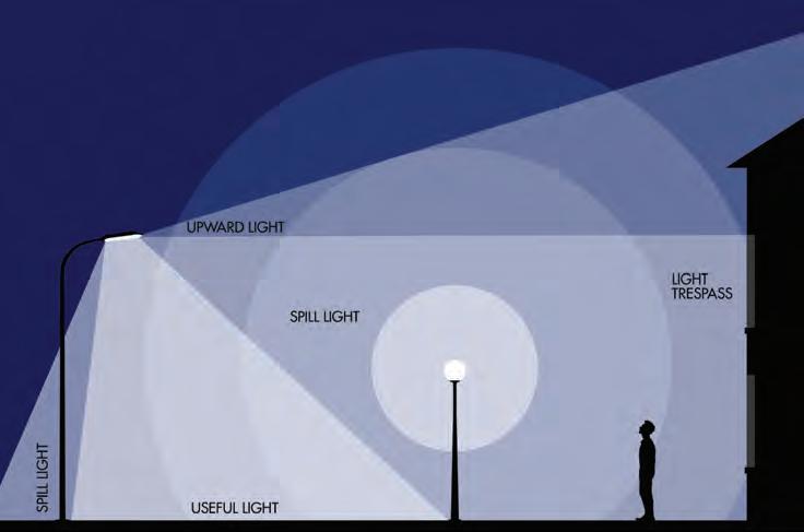
• Recommendations on obtrusive light & unwanted light pollution.
• Recommendations of illuminated signage.
• Overview of illumination levels.
Illustrative Proposal | Provided by Studio Egret West
2. Considerations
2.1 Challenges
Any proposed lighting strategy should acknowledge the various key design challenges which must be balanced within the overall scheme by offering technical lighting solutions throughout.
Security:
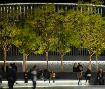
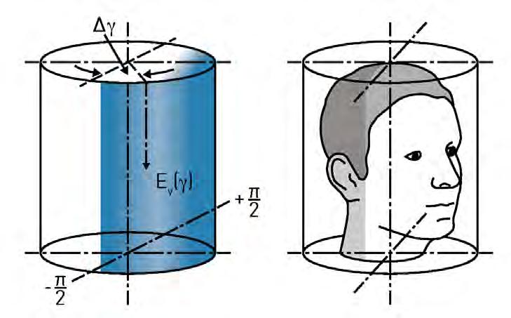
Well designed lighting can help maintain a safe and secure environment and will often deter crime and antisocial behaviour. Providing sufficient vertical illumination to aid CCTV surveillance and enhances facial recognition.
Safety:
Safety of users is paramount in any scheme, good lighting practices can help highlight potential hazards e.g. edges, and changes in levels. By illuminating these areas positively, helps from both a safety and wayfinding standpoint.
Accessibility:
All design should be fully inclusive and therefore special attention should be considered within the lighting scheme to provide a design which also offers elements suitable for the visually impaired, again with special attention to zones with potential hazards.
Flexibility:
Both the interior and exterior spaces should offer a ‘future-ready’ approach, by offering longevity to the design and the potential to expand should it need to in the future. Ensure that both the lighting control and infrastructure can be easily amended and/or removed is a key feature which needs to be addressed.
Sustainability:
Artificial light allows spaces to be utilised in the night-time environment, however careful considerations will be given to ensure that this is used sensitively throughout. By using luminaires which offer efficient light sources, offer circular economy where available and luminaires which have been designed with definite/substantial progress towards circularity. Through the
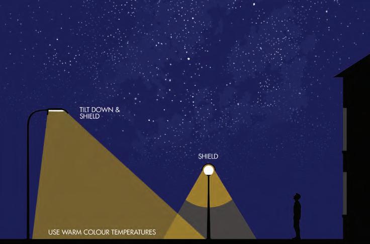
use of a dedicated intelligent lighting control system, this will limit the potential impact. A key factor within the lighting design is to protect the night-sky from light pollution. Placement, control and aiming will be controlled to avoid as much upward light as possible, whilst the lighting control system will ensure lighting is set at the appropriate levels throughout the day/night.
Maintenance:
Even though a key benefit of LEDs are their long lifespan, regular maintenance is required to ensure the longevity of fittings but to also maintain a consistent level of light, as lighting equipment can become dirty over time. Fitting placement or technical requirements such as hinged columns are a key element to avoid unwanted risk or disruption to the site.
2. Considerations
2.2 Qualities of Light
Lighting has often been seen as a way to extend the day, however the nighttime environment should be considered in its own right for its own unique qualities, which creates opportunities to use light to enhance and inform spaces by using the following tools.
Intensity:
How much light falls on a surface (illuminance) and how bright surfaces appear (luminance) are the main points of measuring within lighting design, so how luminaires are specified for their output is key to the design composition.
Colour:
Light and its colour and how it is used is fundamental, whether that is the hue/saturation of a coloured source or even in the subtleties of white light itself. This strategy outlines how colour should be used throughout and how it enhances the tone and texture of materials.
Scale:
Perception of space can be altered through light, spaces can feel smaller or larger dependant on the balance of light within the space, but also the scale and form factor of light fittings should also be carefully considered to fit within the overall architecture and the space.
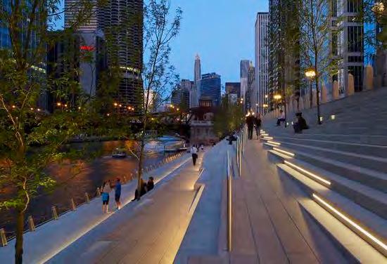
Verticality:
The use of vertically illuminated surfaces is extremely important and brings together a fully-rounded and positively lit space which offers comfort and enhances the feeling of safety to users.
Balance:
Through the careful composition of light, it’s intensity, contrast, colour and direction offers a space filled with life and a truly holistic approach to the space.
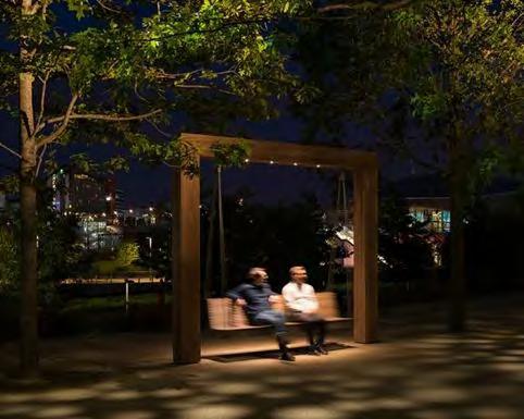
Darkness:
Spaces which are filled with a bright uniform level of light often appear cold and dull. The true balance is that of light and shade it creates depth, life and tone. It informs nuances within the architectural forms and landscape. Provides spaces within spaces allowing users to feel safe and offers areas to sit and dwell, removed from the busy open spaces into areas of contemplation.
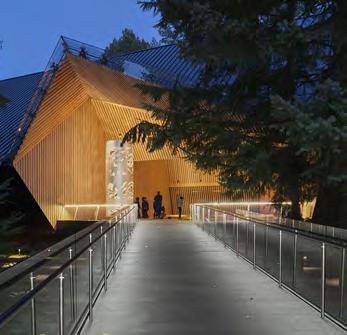
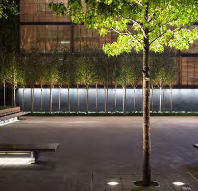
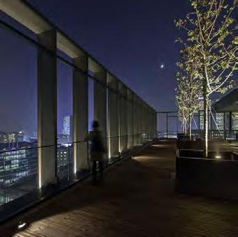
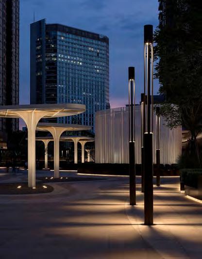
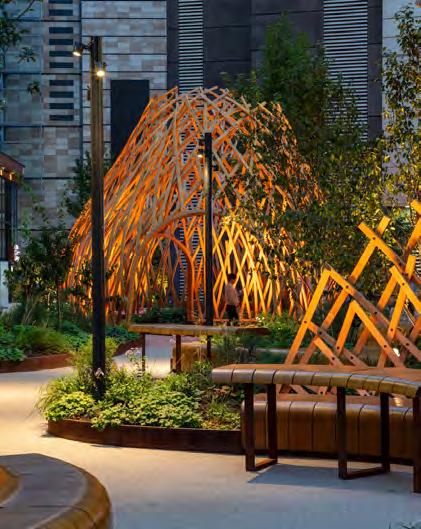
MF Pavilion, Mexico Audain Art Museum, CanadaJakobsbergsgatan, StockholmMunicipal Building, Rieti Wharf Green, Swindon Fintech Building, Milan
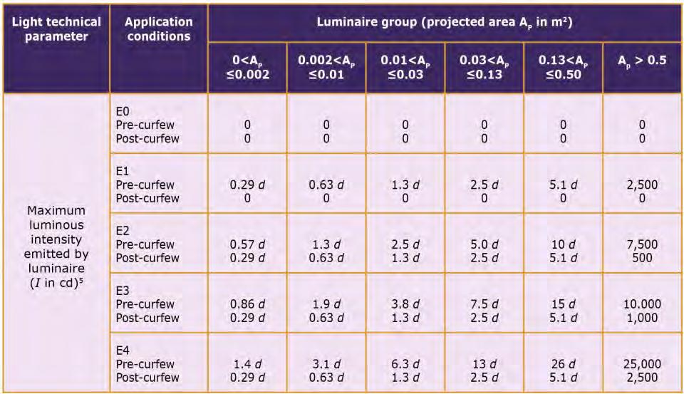
3. Lighting Criteria
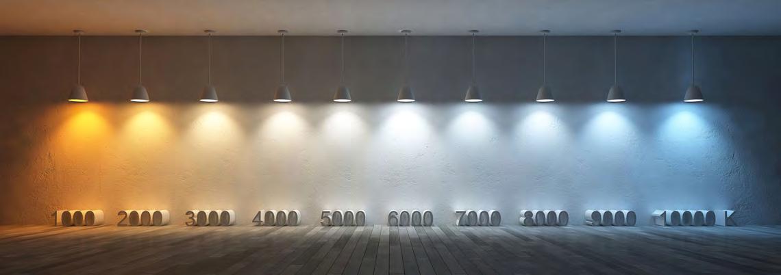
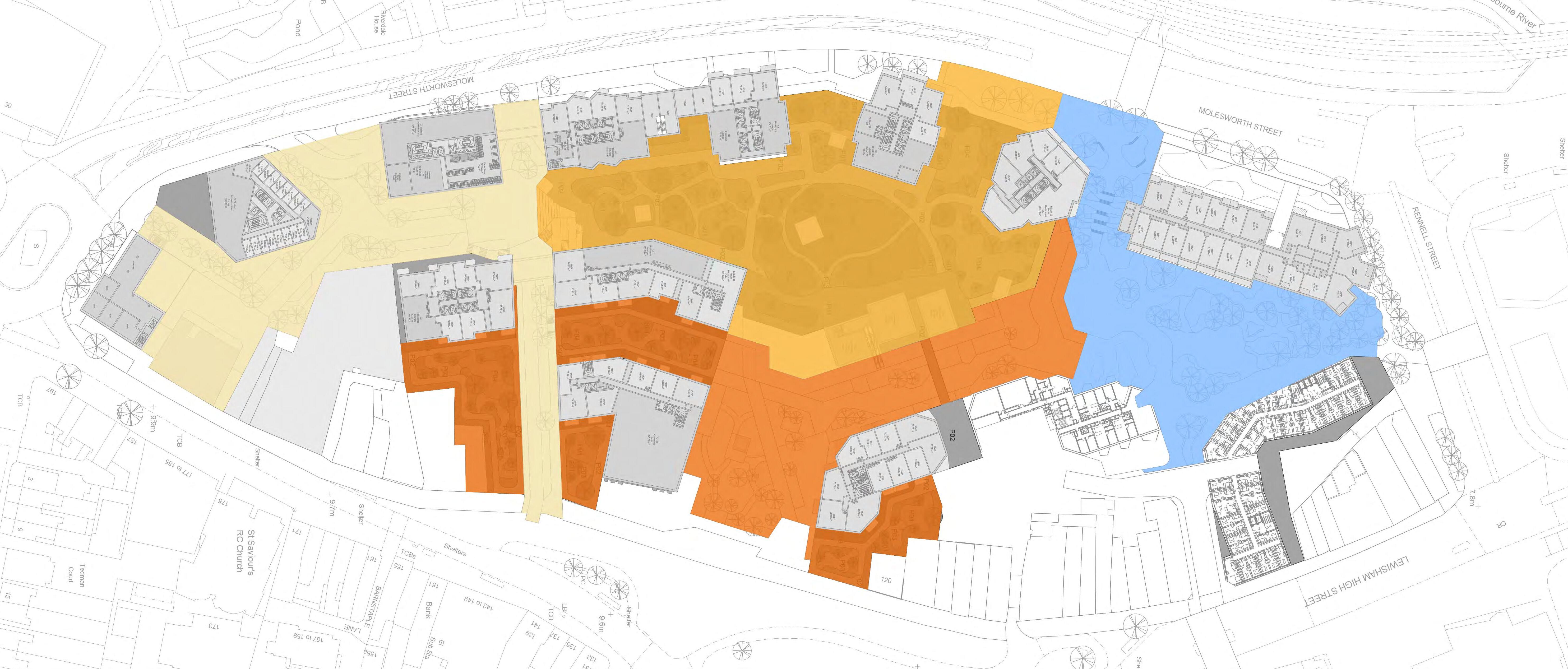
3.1 Colour Temperature
The colour temperature used within the scheme should not only provide the illuminance required for navigating the site but also enhance the material and surface quality.
When considering the project as a whole, in terms of materiality four key fundamental areas have been taken into consideration and is graphically shown in section 3.2.
Each environment has its own unique appearance and personality therefore, should be lit to play upon their juxtapositions and material quality but also convey a sense of belonging upon the overall environment.
By combining variations of white light, which occur naturally during the day. A subtle colour story is woven throughout, underpinning each of the areas qualities and culminating in a seamlessly blended sunset of light which can be viewed from within and also whilst looking down into the site.
Tuneable white lighting is also an option, this provides dynamic changes in the tone of white light which can change in tone over time. An option could be to use this at curfew to provide a subtle shift, together with dimming the intensity of light down to automatically move people on to their next journey and leave the public spaces until their next visit.
Examples of colour temperature, both in the natural environment and also within art projects and installations.
01. Time-lapse showing changes in colour throughout the day, Meg Orlinski.
02. Colour temperature diagram.
03. Halo Horizon, Mandalak.
04. The Weather Project, Olafur Eliasson.
The suggested colour temperature for each area is described as:
3000 Kelvin or cooler to provide a warm and inviting entry point.
2700 Kelvin or warmer to provide a smooth transition between the areas.
2500 Kelvin or warmer reducing the blue wavelength to be kind to fauna and flora.
2200 Kelvin to create a warm and welcoming environment.
Colour Temperature Plan, Background plan supplied by Studio Egret West
Colour Temperature Plan
3. Lighting Criteria
3.3 Retail Illumination & Signage
The retail environment and how this works with the overall site is key to how people move throughout the space.
Lighting from the internal areas will contribute to the overall light levels within the connecting exterior areas, therefore it is extremely important for this to be controlled and conform to relevant guidance. This will minimise any obtrusive light to the public realm, control glare and most importantly not compromise the safety of users.
The following criteria should be taken into consideration:
• Minimise visible light sources.
• Avoid glare from both direct and/or indirect light sources.
• Interior lighting switched off after hours, unless it forms part of a window display.
• Window display lighting is encouraged to remain on until curfew however, it should be set at a reduced output if possible.
• Colour temperature should be coordinated to be consistent throughout.
• High quality light sources to be utilised as standard to have a colour rendering index (CRI) value of 80 or greater.
The same criteria should apply to illuminated signage. The brightness should be considered for legibility but should also offer a level of control to allow for the reduction of light emitted as the environment changes.
As these elements form part of the overall look and feel of the site it is important that these are balanced to provide a holistic approach.
All illuminated shop fronts and signage should comply with relevant fit-out guidance and adhere to information outlined in the ILP guidance.
Precedent examples of various retail display windows and illuminated signage.
01. Externally lit signage.
Internally illuminated signage.
Edge lit letter, Product image.
Hermès window, Barcelona.
Martino Gamper, Prada, Milan.
3. Lighting Criteria
3.4 Light Pollution & Obtrusive Light
Light pollution, or obtrusive light, can create serious physiological and environmental problems. Light pollution can be classified as:
• Sky glow: The brightening of the night sky above the occupied area.
• Glare: The discomfort created by a light source in contrast to the background.
• Light trespass: The spill of light beyond the site boundary on which the light source is intended to be.
• Light ingress: The passage of light into properties from external light sources. Obtrusive light can be a problem for both humans and wildlife as well as a waste of energy and a contribution to CO2 emissions.
During the design phase of a lighting installation, consideration of the following measures to reduce the occurrence of obtrusive light is taken.
• Over-lighting: This can be avoided by conducting detail lighting calculations and selecting the correct lighting equipment for the correct application. Appropriate lighting controls can also ensure that light levels are kept within the desired limits.
• Luminaire technology: Careful consideration to the selection of the luminaires and light sources to minimise any unwanted light. Luminaires with a controlled light distribution will be utilised to ensure they illuminate only the intended areas.
• Luminaire aiming: All lighting equipment will be positioned to avoid uplight and carefully aimed towards the task area. This can be ensured during the commissioning stage.
The exterior illuminance levels are dependant upon the district brightness where the lighting is specified for. The district brightness is determined according to criteria described in the Institution of Lighting Professionals (ILP) guidance notes and requires knowledge of the local area.
Figure 2 | Good example of obtrusive light (Blinded by the Light? - Dark Skies Commission).
Figure 1 | Bad example of obtrusive light (Blinded by the Light? - Dark Skies Commission).
3.5 Obtrusive Light - Site Classification
The criteria used to provide a baseline for the impact of lighting on the surrounding environment are taken from the ILP GN01 2021: Guidance Notes on Obtrusive Lighting.
The five potential zones are detailed in Table 1. It is assumed that the development will fall into Zone 4 of the ILP Environmental Zone guidance. Limitations imposed upon the exterior lighting within an E4 Environmental Zone are provided in the adjacent tables, extracted directly from the ILP GN01 2021 Guidance. Further guidance on limitations and how these are calculated is provided in CIE 150:2017.
Table 2 | ILP Guidance Note GN01 2021 - Maximum values of upward light ratio (ULR) of luminaires
Table 3 | ILP Guidance Note GN01 2021 - Limits for luminous intensity of bright luminaires
Table 4 | ILP Guidance Note GN01 2021 - Maximum values of vertical illuminance on premises
3. Lighting Criteria
3.6 Safety & Security
The safety of pedestrians and staff is always a key design consideration therefore, a balanced approach must be taken when considering safety within the night-time environment. Many research papers have been developed to show that high levels of brightness don’t necessarily equal safe environments.
Areas that are illuminated with a blanket level of high output light such as underpasses or car parks have the tendency to make the public feel threat, this is due to the lack of nuance and focal points in the lighting design. This can have a negative effect on the space and deter people to explore further.
In order to create a safe environment, the various areas must be considered holistically. Lighting should be developed in layers offering good illumination both vertically and horizontally enriching the space, aiding wayfinding and providing focal points to offer spaces which allow the visitor to move unaided in a safe well balanced area. Successful lighting designs can draw the public into the area, well inhabited areas are naturally safer environments, drawing on the theory of safety in numbers.
The perception of light and how it is used also adds to safety. Adding lighting at a pedestrian scale offers clear facial recognition which again makes us feel safer.
Choosing where to add light and texture is a carefully woven composition which provides a lower level of light without having a large impact to the night sky and offering a safe night-scape.
Existing project imagery which features high-levels of design which improve the feeling of security afterdark.
01. Queen Elizabeth Park, London.
Chicago Riverwalk, Chicago.
King’s Cross Plaza, London.
3. Lighting Criteria
3.7 CCTV & Facial Recognition
Safety and security are intrinsic to the feeling of comfort and well-being within the site in both the daytime and the night-time environment. Providing a level of appropriate light and uniformity of light is essential for CCTV at night.
The quality of light used at night is fundamental to the operation of good imagery for CCTV. The following are aspects which will be closely considered for light placement and specification.
• High Colour Rendering (CRI) properties, 80 CRI or above.
• Shielded/deep recessed light sources where possible to minimise glare.
• Avoid direct light adjacent or in direct view of the camera lens.
• Vertical illuminance to provide accurate facial recognition.
• Luminaires mounted at pedestrian scale, and to provide good facial recognition.
• Ensure light coverage of area and avoid areas of darkness.
Horizontal illuminance is usually calculated on the floor level. However, this parameter does not take into consideration light landing on the vertical elements such as trees, buildings, signage and people.
Good vertical illumination is necessary to give the observer a bright and open spatial impression, to model the objects in the field of view, allow their identification hence to increase the feeling of safety particularly in the external environment at night.
The semi‐cylindrical illuminance, is the parameter which in lighting assesses the light falling on a semi‐cylinder which abstractly represents a person face. This allows the face identification of pedestrians approaching each other. This parameter is of extreme importance in with a higher crime risk area for the identification of people and objects.
Lighting is to be closely coordinated with the project security representative to ensure all necessary criteria is met and a maintenance strategy is in place to ensure this remains throughout the life of the project.
The lighting control system will have a dedicated security scene, which will be enabled to provide a lower consistent level of light throughout non-operational hours to ensure CCTV can capture images.
Semi cylindrical illuminance
3. Lighting Criteria
3.8 Lighting Controls
The lighting control system will be designed to optimise light levels required between sunset and late at night when most buildings are closed. The control system should consider energy savings when appropriate but also provide enough light for visual comfort and safety to attract visitors into the spaces.
All lighting elements located throughout the public realm will be controlled from a central location which makes it possible to group luminaires and/or pre-program a number of ‘scenes’ which can be activated at specific times to create a desired mood, aesthetic and light level across the site in conjunction with the building skin and interior illumination strategy.
As the landscape lighting is required after sunset, the control system should link to light sensors located at appropriate zones on the site. These should be mounted under open sky. Once the light levels drop under a certain value, preprogrammed luminaires within the landscape lighting system should switch on.
To promote sustainability and reduce energy usage additional use of time clocks could ensure that not all luminaires switch on at the same time or remain switched on during the complete night. It is envisaged that, when the buildings are in use, all functional and decorative lighting will be switched on but once the buildings close down, only light for safety and security (including CCTV coverage), evacuation and emergency, or dedicated loading and entrance/ exits areas should remain functioning.
The selection of appropriate luminaires should be discussed with the appropriate consultants, landscape architects, and client staff.
The lighting principles could be grouped and appointed to certain ‘light scenes (to be discussed with landscape architect):
Scene 1 | During Sunset
All functional circulation lighting will be activated.
Scene 2 | After Sunset/Evening
As this is the busiest time of the evening that the spaces will be populated and the night sets in, it is envisaged that all lighting could be switched on.
Scene 3 | At time of and/or After building closure
The decorative lighting will start fading, to alert the visitors the site is closing down. When all visitors have left, only the lighting for safety and security, evacuation and emergency, or dedicated loading and entrance/ exits areas remains functioning.
Scene 4 | Event Lighting
Event lighting should be considered when/where required and only used at the discretion of the centre management. Event lighting will over-ride Scene 3 until the event curfew when it will revert back.
3. Lighting Criteria
3.9 Circular Economy & Sustainability
When selecting luminaires for any lighting scheme, the manufacturers approach to the circular economy and re-purposing of their lighting fixtures should be considered by the lighting designer, including where they source luminaire materials, their location, how luminaires are shipped and C02 emissions.
By using criteria set-out in CIBSE TM66:2021 we can assess the specification for its compliance to circular economy.
Utilising the Circular Economy Assessment Method (CEAM) allows specifiers to engage with the manufacturer through the Circular Economy Assessment Method for manufacturing (CEAM-Make) which provides performance information and its supporting ecosystem in terms of circular economy.
The products are given a score from 0-4 (from ‘zero’ (0) to ‘hero’ (4) as outline in the table below, providing a clear assessment for specifiers.
0 No evidence No evidence has been seen. Any product, material or service displaying typical linear economy principals is to be allocated 0 marks.
1Some positive evidence Design elements have been considered, and evidence provided.
2 Positive evidence
3Excellent positive evidence
4 Outstanding
Design elements/attributes have been incorporated into the product or service offered.
Design elements/attributes have been incorporated into the product or service offered, and services align with circular economy goals.
Design elements/attributes and services align with circular economy goals and deliver ecological regeneration or are regenerative to communities or via social responsibility.
CEAM: evidence and action towards a circular economy - CIBSE TM66:2021
Score Evidence Action toward circular economy
4. Technical Assessment
The project lighting design criteria has been developed to lighting regulations and guidelines developed by the British Standards Institute (BSI), the Institute of Lighting Professionals (ILP) and the Society of Light and Lighting (SLL/ CIBSE) to ensure that the project conform to responsible energy use, appropriate light levels, visual comfort and are easily maintained.
The lighting will be designed using the following documents for guidance and best practice.
• BS EN 12464-1:2021: Light and Lighting - Lighting of Indoor work places.
• BS EN 12464-2:2014: Light and Lighting - Lighting of Outdoor work places.
• BS 5489-1:2020: Lighting of roads and public amenity areas.
• BS 8300-1:2018: Part 1 External Environment - Code of practice.
• BS 8300-2:2018: Design of an accessible and inclusive building environment.
• SLL Code for Lighting 2022.
• SLL Lighting Guide LG 06: The Exterior Environment (2016).
• SLL Lighting Guide LG 14: Control of Electric Lighting (2023).
• SLL Lighting Guide LG 16: Lighting for Stairs (2017).
• ILP GN01-21: Guidance Notes on Obtrusive Lighting.
• BREEAM UK New Construction 2018: Ene 03 External Lighting.
• ILP Professional Lighting Guide 05/22: The brightness of illuminated advertisements including digital display (2023)
The following illuminance plans have been created to show best practice illuminance and uniformity levels in relation to the current masterplan layout. The illuminance levels are given as guidance, to ensure that the relevant standards and guidance are followed. Implementation of the listed Standards and guidance remain relevant as the masterplan develops. As a result, the lighting scheme will be sensitive to it’s surroundings and provide the relevant levels of illuminance and uniformity for safety and security.
Primary Pedestrian Only Routes
Maintained Minimum 5lux, 0.25U₀ | BS EN 12464-2:2014
Secondary Pedestrian Only Routes
Maintained Minimum 5lux, 0.25U₀ | BS EN 12464-2:2014
Landscape Focal Points Pedestrian Only
Maintained Minimum 5lux, 0.25U₀ | BS EN 12464-2:2014
Entrance Gateways
Maintained Minimum 20lux, 0.40U₀ | BS EN 12464-2:2014
Boundary Pedestrian Route
Maintained Minimum 20lux, 0.40U₀ | BS EN 12464-2:2014
Pedestrian Route in Traffic Areas
Maintained Minimum 20lux, 0.40U₀ | BS EN 12464-2:2014
Dual Use Traffic Zone, Drop-off and Parking
Maintained Minimum 50lux, 0.40U₀ | BS EN 12464-2:2014
Stairs & Escalators
Maintained Minimum 50lux, 0.40U₀ | BS EN 12464-2:2014
Out of Scope
Primary Pedestrian Only Routes
Maintained Minimum 5lux, 0.25U₀ | BS EN 12464-2:2014
Secondary Pedestrian Only Routes
Maintained Minimum 5lux, 0.25U₀ | BS EN 12464-2:2014
Landscape Focal Points Pedestrian Only
Maintained Minimum 5lux, 0.25U₀ | BS EN 12464-2:2014
Primary Pedestrian Only Routes
Maintained Minimum 5lux, 0.25U₀ | BS EN 12464-2:2014
Secondary Pedestrian Only Routes
Maintained Minimum 5lux, 0.25U₀ | BS EN 12464-2:2014
Landscape Focal Points Pedestrian Only
Maintained Minimum 5lux, 0.25U₀ | BS EN 12464-2:2014
Play Areas
Maintained Minimum 20lux, 0.40U₀ | BS EN 12464-2:2014
Please Note:
All areas have been considered at their current use, should these change then the lighting levels will require re-evaluation. The uniformity levels will need to be coordinated with the security consultant at Stage 3 to ensure that the cameras can obtain quality analytics with 0.25U₀.
APPENDIX 3
FIRE STATEMENT
LEWISHAM SHOPPING CENTRE
Project Lewisham Shopping Centre - Masterplan
Report Title Outline Fire Strategy
Our Ref JL9662/R1/Issue 3
Project Lewisham Shopping Centre - Masterplan
Report Title Outline Fire Strategy
Report No JL9662/R1
Issue No Issue 3 Issue Date 18/10/2024
Date 02/09/2024 02/10/2024 18/10/2024 By PM AP EH
Checked EH EH PM
Approved NH PM PM
1.0 INTRODUCTION
2.0 LONDON PLAN 2021 – POLICY D12 FIRE SAFETY
3.0 QUALITATIVE DESIGN REVIEW
4.0 ACTIVE FIRE SAFETY SYSTEMS
5.0 SITEWIDE FIRE VEHICLE ACCESS
6.0 ENCLOSED SHOPPING CENTRE
7.0 PEDESTRIAN STREET AT LEVEL 1
8.0 SERVICE YARD
9.0 SECOND FLOOR COMMUNITY GARDEN
10.0 RESIDENTIAL BUILDINGS
11.0 STUDENT RESIDENTIAL
13.0 MUSIC VENUE
14.0 STRUCTURE AND COMPARTMENTATION
15.0 ROOFS, ELEVATIONS, AND EXTERNAL FIRE SPREAD
16.0 CONSTRUCTION PHASING
17.0 INFORMATION, LIMITATIONS AND ASSUMPTIONS
1.0 INTRODUCTION
1.1 Description of
Site
The Lewisham Shopping Centre development is a mixed use scheme on the site of the existing Lewisham Shopping Centre.
The existing shopping centre will be demolished and replaced over a number of phases with a new shopping centre alongside a number of separate buildings constructed either above or adjacent to the new centre. Figure 1 below shows a schematic of the site. For the purposes of this Strategy, the illustrative scheme has been considered.
The shopping centre will comprise a single storey covered mall at ground level comprising a mix of both retail and food and beverage units.
There will be an open air pedestrian street at podium level (Level 01) which will provide access to further food and beverage units. This podium is accessible from both the High Street and Molesworth Street by a series of external steps and lifts. There is also a service yard at Level 01.
There is an extensive park at Level 02 which can be accessed by residents directly from the stair cores serving their buildings as well by the public via external steps and lifts leading up from the pedestrian street at Level 01.
The buildings vary between four and 35 storeys high and are predominately residential
Building N3 is the existing Citibank Tower which will be extended and increased in height.
Building MV in the southernmost corner of the site will be a cultural facility / music venue.
Through a Hybrid planning application, detailed planning permission is being sought for Buildings N1 and N2 with outline planning permission being sought for the rest of the site.
Figure 1: Site Diagram and Plot Numbers
1.2 Purpose of this Report
This outline masterplan fire strategy describes the fire strategy principles that will be adopted for the site as a whole. It identifies the active and passive fire safety features, escape arrangements and firefighting access facilities that will be provided to satisfy both Building Regulations requirements and Policy D12 and D5(B5) of the London Plan
Separate Fire Safety Statements will be provided for N1 and N2 as part of the detailed proposals. The fundamental fire strategy principles will nevertheless be consistent across the entire site.
1.3 Approach to Fire Safety
The Building Regulations require buildings to be designed to achieve a reasonable standard of safety for occupants in and around the building. The following sections describe the fire strategy arrangements that will be provided in each of the buildings on the masterplan.
The fire strategy design approach draws from contemporary guidance including the Building Regulations Approved Document B Volumes 1 and 2 taking into account the most recent updates to these standards from earlier this year. Other guidance such as BS9991 and BS9999 will also be used to inform the fire strategy.
At the time of preparing this report it is recognised that the government are consulting on further changes to guidance and BS9991 is also due to be revised later this year. Emerging best practices have informed the design.
This is a very large and complex mixed use scheme. Careful attention needs to be paid to the interfaces particular between residential and non residential uses to ensure that an appropriate standard of safety is achieved. All residential buildings will be designed with a minimum of two escape stairs in line with emerging best practice and the design solution will also provide step free escape routes to ensure that all building users can escape in a dignified manner.
Due to the complexities of this scheme and the interfaces there will inevitably be some areas where it is not possible to comply with standard guidance or where complying with that guidance would result in a sub optimal standard of safety. In these instances fire engineering solutions will be explored to deliver the most effective fire safety solution.
The residential buildings are classified as HRBs. Many of the towers are also classified as tall or very tall buildings as they have floors more than 50m above Ground level. The intention is to commence a Qualitative Design Review (QDR) for the entire masterplan during the next design stage This will involve a variety of stakeholders both from the project and client teams as well as the regulators to ensure the adequacy of the overall safety case.
1.4 Declaration of Compliance
Jensen Hughes have been appointed to provide fire strategy advice on the masterplan. Jensen Hughes are a highly experienced team of specialist fire engineers that have been operating in the UK and Ireland for nearly 30 years (predominantly under the name JGA). The qualifications of the authors of this report are given below:
Report by Paul Macken MSCi, MIFE, and CEng
Checked by Eadwyne Henry MEng, AIFireE
Approved by Nick Harvey BEng (Hons) CEng MIFireE
2.0 LONDON PLAN 2021 – POLICY D12 FIRE SAFETY
3.0 QUALITATIVE DESIGN REVIEW
BS 9991 specifically addresses the approach to tall and very tall buildings in Section 0.7.
Figure 2: BS9991 Tall Building Guidance
The guidance recommends that a Qualitative Design Review (QDR) is be carried out for all buildings that have floors more than 50 m above ground. The QDR process will establish if any additional fire safety systems or features are needed as part of the overall safety case. It will involve a variety of stakeholders including the client, Building Control and/or new Building Safety Regulator (BSR), London Fire Brigade and the design team.
The QDR process will commence in the next design stage and will consider the entire site and not just those buildings that are classified as tall buildings. This will ensure consistency of the fire engineering design approach across the entire masterplan.
4.0 ACTIVE FIRE SAFETY SYSTEMS
4.1 Sprinklers
4.1.1
Apartment Buildings
All apartment buildings will be sprinklered Sprinklers are designed to control fires and restrict the maximum size the fire could grow to. They may even extinguish the fire. The risks and consequences of fire on residents’ safety are greatly reduced in sprinklered buildings.
Sprinklers will be provided in apartments in accordance with BS 9251 – 2021: Fire sprinkler systems for the domestic and residential occupancies – Code of practice. Sprinklers will be designed to Category 4.
The communal and ancillary residential areas will also be sprinklered. Some of the communal residential facilities may need to be served from the commercial standard sprinkler system (see 4.1.2) This will be developed in subsequent design stages.
The sprinkler system is to be designed as a life safety system. The design of the sprinkler systems is to be developed in consultation with an accredited sprinkler designer.
4.1.2 Commercial Areas
All commercial areas will be sprinklered. This includes shops, food and beverage units, offices, car parking, service yards and all other similar areas. Sprinklers provided to the commercial spaces will be in accordance with BS EN 12845 – 2015: Fixed firefighting systems Automatic sprinkler systems Design, installation and maintenance
The one exception to this would be the music venue which doesn’t require sprinklers to comply with Building Regulations guidance due to building height or compartment size. It is, however, recommended that this space be sprinklered if it is practical to do so.
4.2 Secondary Power Supply to Life Safety Systems
All life safety systems within the buildings will be provided with back-up power in line with the recommendations of BS 9991:2015 and BS 9999:2017.
4.3 Signage and Emergency Lighting
Signs will be provided on common escape routes and in accordance with the recommendations of BS 9991:2015 and BS ISO 3864-1:2011.
Floor identification signs and flat indicator signs will be provided to assist fire fighter wayfinding. These signs will be in accordance with Clause 15.13 and 15.14 of Approved Document B Volume 1 (2019 edition incorporating 2020 amendments).
Emergency lighting will be provided in accordance with BS 5266-1:2016.
5.0 SITEWIDE FIRE VEHICLE ACCESS
5.1 Site Wide Fire Vehicle Access
It is essential that fire vehicles can drive into and through the site to ensure that each building or area is readily accessible. Figure 3 below shows the illustrative ground floor plan and indicates the extent of fire vehicle access routes around and through the site.
Figure 3 – Site fire vehicle access routes
The roads and any pedestrianised areas will be designed for fire vehicle access based on the recommendations of the Approved Document B. The specifications for widths, clearances, and carrying capacity of roads are given in Figure 4 The landscape design within the pedestrianised areas needs coordination to ensure that the landscaping design adequately accommodates the required fire vehicle routes. This will be developed in more detail as the design progresses.
Fire fighting stairs, fire fighting lifts and fire mains will be provided in each of the residential buildings The shopping centre will also be provided with fire fighting stairs. Therefore, the vehicle access routes need to be suitable for a pump appliance. It is, however, anticipated that the main public roads would also be suitable for high reach appliance access also.
It is understood that the vehicles used by the London Fire Brigade require a higher load bearing capacity of 14 tonnes rather than the 12.5 tonnes given in the guidance in Figure 4
5.2 Dead-End Fire Vehicle Access
The fire vehicle access routes shown in Figure 3 are generally continuous providing a through route with the exception of a dead end condition to the rear of Building N2 A facility e.g. a hammerhead (see Figure 5) or similar will be provided to allow a fire vehicle to turn around.
It is possible that as the masterplan evolves that some further dead-end routes could be created.
In these situations, the fire vehicle access routes will be arranged such that fire vehicles do not have to reverse more than 20m. Any dead-end roads that exceed 20m in length will be provided with turning facilities in accordance with the guidance given in Figure 5
Figure 4 - Guidance on Fire Vehicle Route Specifications for Fire Vehicles
5.3 Fire Vehicle Access to and within Buildings
The fire fighting arrangements within buildings are discussed in the following sections for each of the uses.
The vehicle routes shown in Figure 3 do, however, provide suitable access to the building entry points enabling fire fighters to respond in an effective manner. This will, however, be monitored as the design develops and any necessary adjustments will be made on a building by building basis.
In the Illustrative Scheme, the primary cores to Buildings C2.1 and C2.2 are accessible from the pedestrian street at ground floor at the southern end of the shopping centre. The secondary cores from each building are not, however, accessible from ground and instead exit onto the first floor pedestrian street. This needs further review as fire vehicles are not able to access this first floor street.
This is the secondary core and neither building is especially tall (13 and 9 storeys respectively). On that basis it may be sufficient to provide wet risers and for fire fighters to use the external steps from the High Street to reach the building entry points at first floor level. This would involve a walking distance of up to 55 m but is justified by the fact that the building has wet risers and adequate hose cover is achieved from the primary core alone. If this is not acceptable then another option would be to utilise a transfer corridor at one of the lower levels with access being initially via the primary core.
5.4 Hydrants
The guidance in the Approved Document B states that if there is an existing fire hydrant within 100m of the building then additional fire hydrants are not required.
The location of existing hydrants is not known at the time of preparing this report. This is, however, a welldeveloped area and there will be existing fire hydrants in and around the site which are likely to be adequate. However, the exact location of the hydrants will be established in subsequent design stages in order to confirm that the existing arrangements satisfy the criteria in the Approved Document B.
If shortfalls are identified in fire hydrant provision, then new fire hydrants will be provided in accordance with the guidance in the Approved Document B e.g. such that they are within 90 m of the dry fire main inlets.
5.5 Bollards and Similar Features
Any bollards and similar features to protect against unwanted vehicle movement will need to be demountable to enable the fire service and other emergency services to access the site in line with routes given in Figure 3. The arrangements will need further development as the scheme progresses.
Figure 5 – Fire vehicle turning requirements
6.0 ENCLOSED SHOPPING CENTRE
6.1
Approach
The shopping centre fire strategy design will draw from the guidance available in BS9999. It should, however, be noted that this guidance is based on older guidance in the now withdrawn BS5588 Part 10, which is now over 30 years old and doesn’t necessarily reflect current best practice. Fire engineering solutions may be required to develop more efficient and effective fire safety solutions.
6.2 Escape Strategy for Ground Floor Covered Mall and Shops
The shops (with the exception of small kiosks) will be provided with at least two means of escape. One will be into the mall via the shop front entrance and another via a shared service/escape corridor to the rear.
The mall is the primary access route to the shops and consequently forms a critical part of the escape route system. It is the familiar route and therefore the route most likely to be used by shoppers during a fire evacuation.
The mall has a cruciform arrangement with main entrances into the two pedestrianised areas to the north and south as well as entrances onto Molesworth Street and the High Street. These four main entrances provide most of the escape capacity from the mall but this will be supplemented by shared service escape corridors where necessary to meet travel distance parameters as shown in Figure 6 below (typically < 90 m between adjacent mall exits)
Figure 6 – Ground Floor Mall and Escape Routes
The escape routes will be sized to deal with the calculated occupancy following the principles in BS9999. It is recognised that some of the shops are intended for higher occupancy uses e.g. Food and Beverage and this will be taken into account in the design of the escape routes.
The service/escape corridors will be sized to deal with the occupancy of the mall or largest shop escaping into them whichever is greater. An additional 500 mm will be added to the calculated escape width to allow for goods in transit. Service corridors will be at least 2 m wide but will not exceed 3 m wide. In some circumstances it is necessary to provide fire resisting lobbies between shops and service corridors. The service corridors will be further sized and developed in more detail in the subsequent stages.
The escape routes from the ground floor shopping centre are step free and consequently cater for all building users regardless of age or mobility.
Most of the shops have a mezzanine which will be accessed internally via a staircase. The shop mezzanines are currently designated for storage use and accessible only from within the shops with no public access. At least two stairs are likely to be required for escape from each mezzanine.
The strategy for mezzanine escape is to be reviewed further as it may be more efficient for one of the escape routes to be via a landlord service/escape corridor at mezzanine level itself. If this is pursued then stairs and evacuation lifts will be provided in strategic locations to provide step free escape from the mezzanine level.
The escape arrangements will be developed in more detail as the design progresses.
6.3 Smoke Control
Smoke control is provided in shopping centres to protect the mall as it is the most important part of the escape route system from the centre for the reasons discussed earlier in this report.
The most efficient method of smoke control is to allow smoke from a shop fire to flow into the mall where it will be extracted from common reservoirs as shown in the schematic below. The smoke control system is designed to contain the smoke in a reservoir and provide a clear layer allowing occupants to escape beneath the smoke
The smoke reservoirs are formed by the shop front fascia downstands and cross mall smoke reservoir screens constructed from either glazing or smoke curtains. Typically these reservoirs are limited to a maximum of 1,300 m2 and 60 m in length although larger reservoirs are possible subject to further technical analysis.
Preliminary analysis suggests the mall will need four to five smoke reservoirs. Each smoke reservoir will be provided with ducted smoke extract achieving 25 to 30 m3/s which is sufficient to achieve a 3 m clear layer in the mall for a sprinkler controlled fire in a shop. The design of the system needs to be coordinated with the ceiling design to ensure there is sufficient depth to the reservoir and adequate extract points. This will be developed in more detail in subsequent stages.
Replacement air for the smoke control system will be drawn by automatically opening the main entrance doors into the mall
6.4 Large Shops
Larger shops (> 1,300 m2) will need their own smoke control systems.
They may also need to be fire separated from the mall.
6.5 Fire Fighting Facilities
Figure 3 shows that almost the entire perimeter of the ground level shopping centre is accessible to fire vehicles. This would permit fire fighters to tackle fires in the shops from the rear using the service corridors.
Service corridors are, however, not the optimal place to fight shop fires from as they are small enclosed spaces which can rapidly fill with smoke. A better solution would be for fire fighters to tackle shop fires from the mall. This is a much larger space and is protected by a smoke control system designed to achieve a clear layer. The conditions fire fighters would be faced with in the mall would be significantly less challenging than those in a corridor.
To reflect this best practice is to provide fire mains in the corridors immediately behind the doors leading onto the mall to create a bridgehead for fire fighting from the mall
Additional fire mains will be provided in the rear corridors to supplement the routes via the mall and to ensure all areas are within 60 m hose cover.
6.6 Fire Alarm and Evacuation
The enclosed shopping centre will be provided with an automatic fire alarm system. Smoke detection will be provided to an L2 standard with detection provided in both the landlord areas and shops.
Voice alarm will be provided in the mall.
Larger shopping centres are often designed with a progressive or zonal evacuation strategy with the fire alarm zones aligned with the smoke reservoirs. This will be explored in more detail in due course.
6.7 Fire Control Room
A fire control room will be provided in the centre.
6.8
Interface with the Residential Buildings
There are a number of residential buildings which are situated on top of the shopping centre. These buildings will be separated from the residential by two hour fire resisting compartment walls and floors and are designed with separate means of escape.
7.0 PEDESTRIAN STREET AT LEVEL 1
7.1 Escape Strategy
There is an external pedestrian street at Level 1 which provides access to a variety of food and beverage units. This street is accessible via external steps, ramps, escalators, and lifts from the High Street and the pedestrianised area near Molesworth Street.
This is an external street so in many respects will perform in much the same manner as a traditional high street arrangement. Once occupants escape from the fire unit into the external space they are in a place of relative safety and are no longer at immediate risk from fire. Occupants can, however, continue their escape to ground level via the normal circulation routes at either end of this street. The lifts provided at each end will be designed as evacuation lifts to provide step free escape for occupants who may have difficulty using the steps.
The food and beverage units occupy space over two floors – first and mezzanine. Each unit will be provided with two routes of escape at each level The principle escape route at Level 01 will be via the shop front exiting into the open air pedestrian street. The secondary escape routes could be via stairs located within the unit itself or via the landlord service corridors leading to a landlord stair or both.
7.2 Fire Fighting Facilities
The pedestrian street at first floor is not accessible to fire vehicles. Fire fighters can park their vehicles on the High Street and Molesworth Street and use the external steps to reach this higher floor but this does not provide adequate access to the centre of the street.
Consequently, it will be necessary to provide fire fighting stairs to serve these F&B levels. This needs further development and will be coordinated with the servicing strategy as the arrangements for servicing and fire fighting are likely to require stairs and lifts in similar locations The intention would be to provide sufficient fire fighting stairs to achieve 60 m hose cover to all units.
Figure 7 – First Floor Pedestrian Street
Another option that will be explored is whether fire vehicles could also use the adjacent service road to access the first floor, similar to the arrangement in the existing shopping centre, where fire vehicle access is provided to the service deck above the shopping centre. From here the street is accessible via service corridors. Fire mains (either wet or dry) could be provided in these service corridors forming a bridgehead in much the same way as is proposed in the covered mall at ground. This approach may also prove beneficial to the second floor roof garden as discussed in Section 8.
7.3 Fire Alarm and Evacuation
The shops will be provided with their own fire alarm systems. As the shops face onto an external street a fire in one shop should not necessitate the immediate evacuation of any of the other shops.
It is, however, noted that shops will use the shared landlord escape routes in some instances and the entire street and associated F&B units do sit directly on top of the ground floor shopping centre. A significant fire in the shopping centre below may necessitate a wider evacuation. Therefore, it is proposed for the fire alarms to be linked with the shopping centre beneath to provide the functionality to evacuate some or all of the retail areas as required.
The fire alarm systems for the above ground retail units will be monitored in the control room.
8.0 SERVICE YARD
8.1 Escape and Fire Fighting
Two fire fighting cores will be needed to serve the first floor service yard. The most practical location for these is on the Molesworth Street side of the building as this is readily accessible to fire vehicles at ground level Figure 8 below gives indicative locations for these stairs but the exact position is subject to further design development.
These two stairs will also provide escape for occupants in the service road along with the service corridor routes which lead to the external retail street.
8.2 Smoke Control
The service yard is fully covered and will be provided with mechanical smoke extract designed to extract smoke at a rate of 10 air changes per hour.
The residential car parking located adjacent to the service yard will also be provided with smoke extract designed for 10 air changes per hour in accordance with current guidance. It may, however, be necessary to provide enhanced smoke extract to address emerging concerns over the risk of electrical vehicle fires. The need for enhanced smoke extract will be considered further as the design develops.
Figure 8 – Service Yard
8.3 Interface with Residential
There is both car parking and ancillary residential areas at this level surrounding the enclosed service yard. Residents using the car parks will access them via the service road.
The residential areas will be compartmented from the service yard by compartment walls achieving two hours fire resistance. The openings into the car parks will be provided with fire shutters which will close upon detection of fire in the service yard or car park to maintain compartmentation between the different uses
It is, however, recognised that even with these measures in place a fire in the service yard could still present a risk to the residential escape routes due to the indirect connection via the car park. To further protect the residential from a fire in the service yard it is proposed that one residential stair in each tower is designed not to connect to this level ensuring one of the stairs is completely separate at this level. This shouldn’t impact on escape from the residential car park as there are still multiple stairs which would be available for use. The fire strategy principles for the residential amenity areas is discussed in more detail in Section 10.5.
Occupants in the service yard will have their own separate means of escape and do not rely on escape via the residential areas and vice versa.
9.0 SECOND FLOOR COMMUNITY GARDEN
There is an extensive community roof garden at the second floor. This can be used by both the residents of the adjacent residential buildings as well as members of the wider community.
There are three diverse routes providing access to this roof garden and these same routes also provide a means of escape. The public lifts serving this floor will be designed as evacuation lifts to provide a step free means of escape.
Escape does not rely on the use of the residential cores although it is recognised that any residents could use those also if they prefer.
In the illustrative scheme, there are five community and F&B units accessible from this level. At least two means of escape will be needed from each unit. This could be via a combination of either exits directly onto the roof garden which is a place of relative safety or via stairs leading to the levels below exiting at either ground or potentially into the Level 1 pedestrian street which is also a place of relative safety.
The fire fighting access arrangements need further development. One option would be for fire vehicles use the service road from where they can access fire fighting stairs which serve this floor.
Figure 9 – Podium Garden
10.0 RESIDENTIAL BUILDINGS
10.1 Fire Alarm and Evacuation Strategy
10.1.1 Defend in Place / Stay Put Evacuation Strategy
Apartment buildings have traditionally been designed on a defend in place or stay put strategy with each apartment being provided with its own self-contained smoke alarm system.
The stay put strategy is based on the principle that a fire is contained in the flat of origin and the common escape routes are maintained relatively free from smoke and heat. This allows occupants in the other nonfire flats to remain in their own homes. For that reason, apartment buildings don’t usually have a common fire alarm system.
The defend in place strategy will be adopted for the apartments on all residential buildings across the site. However, full evacuation can be initiated by the Fire Brigade as required by using the Evacuation Alert System, see Section 10.1.3 below. The amenity spaces will, however, have a different strategy as discussed below.
10.1.2 Amenity Spaces and Ancillary Areas
The communal/ancillary areas such as residents lounge, gym, roof terraces etc will evacuate immediately upon smoke detection in any of the communal, ancillary, or other landlord areas of that residential building at any level.
10.1.3 Interface with the Retail Areas
A fire alarm activation in the retail or other non residential uses will not result in a full evacuation of the residential parts of the building and vice versa. However, the residential building management will be notified of a fire alarm activation in the non-residential areas.
10.1.4
Automatic Fire Detection and Alarm
All apartments will be provided with a LD1 automatic detection and alarm.
The communal areas and ancillary spaces at ground floor e.g. plant rooms, bin stores, amenity space, gym etc will be provided with minimum L3 automatic detection and alarm.
The common corridors providing access to the apartments on the upper floors will be provided with L5 smoke detection. This system will activate the corridor smoke control system and any associated smoke vents. The fire detection system in the corridors will also be used to raise the alarm in any ancillary and amenity spaces as well as on any roof terrace as these are designed for a simultaneous evacuation upon detection in communal areas.
Audible alarms and visual beacons will be provided on the roof terraces to alert occupants to a fire in the communal areas.
The systems will be designed and installed in line with the relevant part of BS 5839. The design of the systems will be developed in more detail after planning in consultation with an accredited fire alarm contractor.
10.1.5
Evacuation Alert System
An evacuation alert system will be provided to all residential buildings in accordance with BS 8629.
Evacuation alert systems are a facility that will enable the fire brigade to initiate a full building evacuation at their discretion.
10.2 Apartment Layouts
The apartments can either have a conventional cellular layout with the bedrooms and living room connected by a hallway or can be designed with open plan arrangements.
10.3 Escape from Communal Areas
10.3.1
Number of Stairs
All apartments buildings will be provided with at least two stairs in line with emerging best practice and guidance.
The smaller footprint buildings are designed with a central core arrangement. Other buildings are designed with a linear corridor with the stairs and lifts at either end of the corridor. The arrangements are shown in Figure 10.
All residential stairs are designed to exit to a place of safety either at ground floor level or in some cases such as buildings C2.1 and C2.2 one of the stairs will exit into open air street at first floor.
Figure 10 – Residential Buildings
10.3.2 Evacuation Lifts, Lobbies, and Refuges
Evacuation lifts will be provided in all residential buildings across the masterplan to ensure that all building users regardless of their mobility have a safe and dignified means of escape.
Typically the residential buildings have either three or four lifts to ensure there is resiliency in the design should a lift not be operational. Where three lifts are provided these will typically comprise one evacuation lift, one fire fighting lift and one dual purpose fire fighting and evacuation lift. Where four lifts are provided there will be two fire fighting lifts and two evacuation lifts.
The evacuation lifts will be accessed from a fire resisting lift lobby and will be designed to comply with the evacuation shaft concept given in the 2024 revision of the Approved Document B. Smoke management systems will be provided in the communal corridors designed to protect the lift lobby from smoke ingress.
Disabled refuges and associated communications are not normally required in residential buildings as these operate a defend-in-place evacuation strategy. However it is becoming common practice particularly in managed residential buildings to provide emergency communications in the lift lobbies to provide facility for residents to request assistance if they need it.
10.3.3 Communal Corridors and Smoke Control
The apartments in some of the buildings are accessed from dead end corridors. The single direction escape distance in these corridors do not exceed 15 m and complies with Building Regulations guidance.
The longer buildings such as N3, C2.1, and C2.2 have linear corridors with the stair/lift cores towards either end providing alternative routes of escape. Travel distances of up to 30 m to the nearest stair is acceptable in these buildings.
Smoke control systems will be provided in the communal corridors. The smoke control systems will be designed to protect the lift lobbies from smoke ingress. Where necessary the performance of the corridor smoke extract systems will be validated using computational fluid dynamics smoke modelling.
The exact solution will be developed in subsequent design stages but is likely to comprise a fan assisted smoke shaft in the corridor with inlet possibly via a natural smoke shaft located in the lift lobby as this will then encourage airflow from lobby into corridor which should better protect the lift lobby from smoke. Other solutions may be possible and will be explored in due course.
10.4 Fire Fighting Facilities
All of the apartment buildings have floors that are more than 18 m above ground level and will need to be provided with fire fighting stair and lift cores. These fire fighting stair and lift cores will comprise:
• Fire fighting stair at least 1.1m wide
• Smoke vented fire fighting lift lobby
• A fire-fighting lift located within the lift lobby
• Fire main either located in the stair or within the lift lobby (subject to input from the London Fire Brigade as to their preference)
• Smoke vent at the head of the fire fighting stair.
• Walls separating the fire fighting stair, lift and lobby from the accommodation will achieve two hours fire resistance.
Building Regulations guidance recommends that fire vehicles should be able to park within 18m and in sight of the inlet connection to the fire main. The inlet connection is typically located on the face of the building adjacent to the building entry point giving access to the stair and lift. The fire vehicle access routes discussed in Section 5 (see Figure 3) should readily achieve this for most of the buildings although some further work is needed in the case of Buildings C2.1 and C2.2 as discussed earlier in this report
The arrangements will, however, be monitored as the design develops and any necessary adjustments will be made on a case by case basis.
Wet risers instead of dry risers will be provided in buildings that have a top floor height exceeding 50m above vehicle access level. In this case, fire vehicle access will be provided to within 18m and in sight of the emergency replenishment of the suction tank for the main.
Wayfinding signage will be provided within the building to identify each floor in line with the recommendations in ADB Volume 1 in order to assist firefighting operations.
10.5 Amenity and Ancillary Areas
Each of the buildings will contain amenity spaces as well as the usual plant, storage, bin stores etc. Some of the buildings also have some associated car parking.
At least two escape routes will be provided from these amenity and ancillary areas designed to ensure the usual travel distance limitations are met.
It is recognised that some of these spaces may contain a higher fire loading than would normally be found in apartments. The design will consider these risks and provide suitable measures to protect the residential escape stairs. This may involve additional lobbies or specific smoke venting solutions.
Two specific areas of focus will be the car parks at Level 1 (as discussed in Section 8 given their connectivity to the service road) and the cycle stores at Level 1 mezzanine.
The car parks will be provided with smoke extract and it is proposed that at least one of the tower stairs is to be separated from this level to mitigate the risk of fire impacting both stairs
There are emerging concerns over the fire risk associated with electric bikes and scooters. These risks will need to be considered as the design develops and it may be necessary to introduce additional measures to mitigate the risk. For example, it may be prudent to design for only one stair in each tower to connect into these spaces to minimise the risk in the same fashion as proposed for the car parking
10.6 Interface with the Retail and Other Similar Areas
The residential areas will be compartmented from the retail and other similar areas by compartment walls and floors achieving two hours fire resistance.
The residential escape routes are solely for the use of the residential buildings and are not shared with any other use.
11.0 STUDENT RESIDENTIAL
There are two student residential buildings (S1 and S4) within the Illustrative Scheme . These can be designed like traditional apartment buildings with a defend in place strategy following the principles discussed in Section 10. However, some student residential operators prefer to have a simultaneous evacuation solution. At this stage the design is reasonably flexible and can accommodate either approach but this will need to be firmed up in due course.
13.0 MUSIC VENUE
The music venue (Building MV) is located to the south of the site. It comprises 3 or 4 storeys.
A minimum of two escape stairs with associated evacuation lifts will be needed. Additional stairs may, however, be required depending on the design occupancy for the space.
The stairs may need to be designed as fire fighting stairs if the top floor is more than 7.5 m above ground. Fire fighting lifts are not necessary as the building will be less than 18 m high.
14.0 STRUCTURE AND COMPARTMENTATION
14.1
Structure
The structure in most of the buildings will be designed to achieve two hours fire resistance The exception would be the music venue which only needs 60 min fire resisting structure as it is less than 18 m high.
14.2
Compartmentation
Compartment walls and floors will be provided to restrict fire spread within the buildings. This includes:
• All floors in residential buildings.
• All walls separating flats from one another and corridors.
• All floors and walls separating retail and other commercial spaces from residential areas.
• Walls separating retail tenants from each other and from service corridors.
• Fire fighting cores and any associated access corridors.
• Service Yard from all other areas.
The full specification of compartment walls and floors will be developed as the design progresses.
14.3 Ceiling and Wall Linings
The internal wall and ceiling linings will achieve the classifications based on guidance in the relevant volumes of the Approved Document B
14.4 Fire Stopping, Cavity Barriers and Protection of Openings
Measures will be provided to restrict unseen fire and smoke spread within cavities. Cavity barriers will be provided in accordance with the guidance in Sections 8 and 9 of the Approved Document B Volume 1 (residential) and Sections 9 and 10 of Volume 2 (non residential). This includes both internally within floor and ceiling voids and also any cavities in external walls where appropriate.
Openings and similar penetrations in external walls (e.g. for windows, doors etc) will also be provided with appropriate cavity barriers, cavity closers etc in order to achieve the required fire separation as set out in Building Regulations guidance.
Fire stopping will be provided accordance with the recommendations of Sections 8 and 9 of the Approved Document B Volume 1.
14.5 Methods, Products, Materials and Systems
The Building Regulations (Regulation 7) require that building work must be carried out in a workmanlike manner using adequate and proper materials.
Any materials, products or systems will be appropriate for the circumstances in which they are used using tested and certified products that are installed in accordance with the manufacturers design details and instructions and will achieve the minimum requirements of Building Regulation guidance documents.
15.0 ROOFS, ELEVATIONS, AND EXTERNAL FIRE SPREAD
15.1 External Wall Build-up
All residential buildings are defined as relevant buildings as they have floors more than 18m above ground. Consequently the external walls including those of the shopping centre (as by definition this is part of the same building) will be designed to comply with Regulation 7(2) and will be constructed using materials that are either Class A1 or A2-s1,d0 This includes specified attachments such as balconies.
There are specific exemptions noted in Regulation 7(3) and these will be followed as appropriate.
The Music Venue is less than 18m high and whilst not a relevant building it is recommended this be designed to the same standards and the external walls will be constructed from materials that are either Class A1 or A2s1,d0.
15.2 External Fire Spread via the Elevations
The Building Regulations require measures to be taken to minimise the risk of fire spread via the elevations across the site boundary to neighbouring buildings. This can be achieved by locating the building a sufficient distance from the site boundary or by constructing some or all of an elevation from fire resisting construction.
Each building elevation can incorporate some unprotected areas e.g. windows. The site boundary is normally used for the basis of the calculation to determine the permissible amount of unprotected areas in the façade However, where buildings adjoin a road or railway then it is usually acceptable for the relevant boundary to be taken to the centre line of the road for calculation purposes.
In the case where there is no defined site boundary such as for the towers on top of the shopping centre then the assessment will be carried out on a notional boundary located somewhere between the two buildings that works for both.
15.2.1 Residential Buildings
Apartments are separated from each other by compartment walls and floors and are usually well separated from opposing buildings. Because of this there are normally few, if any, restrictions on the amount of glazing to the residential elevations of buildings.
Figure 11 below is an extract from the Approved Document B and applies to apartments. It shows that the elevation of an apartment could be fully glazed (or otherwise unprotected) provided the distance to the relevant boundary is at least 6m. This can be reduced to 3m in the case of these buildings because the apartments will be sprinklered.
Figure 11 – Separation Distance for Residential
The residential towers are generally well separated from one another and from the site boundary or perimeter roads. Preliminary analysis shows that there will be few restrictions on the extent of unprotected areas in the apartments. The exception is south elevation of Building S3 which is approximately 1.7 m from the site boundary. In principle it can still have some reasonably large windows because it is sprinklered but this will need to be reviewed in further detail.
15.2.2 Retail and Similar Uses
Retail units present a greater risk of a severe fire due to the increased fire load and larger compartment sizes compared to residential apartments.
As a guide at this stage, the table below gives a good indication of the allowable percentage of glazing to the elevations of retail and similar accommodation based on the distance to the boundary, i.e. the site boundary or the mid-point of the road. Note that the percentages can be doubled as sprinklers are provided in the non residential uses
Where this table indicates that there are restrictions on the extent of glazing or other openings in an elevation, a more in-depth analysis can be carried out using the calculation methodology given in BR187. Because these analyses are specific to each building or shop, they are likely to show that the actual allowable area of glazing is greater than the simplistic approach above. The provision of sprinklers throughout the retail and other non residential uses will clearly assist
There are, however, some external walls which are very close to the boundary with neighbouring properties and these will likely require fire resisting party walls.
Figure 12 – Separation Distance for Commercial, Retail and Other Similar Spaces
15.3 Roofs
Roofs including any roof top terraces will achieve a BROOF (t4) classification. This is the highest classification for roof coverings given in Building Regulations guidance.
Roof terraces and other roofs that have the function of a floor will also be designed to achieve fire resistance from beneath.
16.0 CONSTRUCTION PHASING
The masterplan will be developed over a series of phases. The fire strategy implications of the construction phasing will be reviewed as the design progresses post planning. This will include the interim strategy when the first phases of the masterplan are constructed prior to the demolition of the existing shopping centre.
17.0 INFORMATION, LIMITATIONS AND ASSUMPTIONS
The information limitations and assumptions used in the preparation of this report are noted below: -
Drawings
This report is based on the SEW Illustrative Masterplan Drawings received on 15 October 2024.
Information
The following information was used for the preparation of this report:N/A
Building Regulations
This report considers building regulations, which deal with life safety. Property protection and insurance issues are not addressed in this report. Guidance on property protection and insurance requirements can be found in the document Approved Document B: Fire Safety (Volume 2) – Buildings other than dwellinghouses Incorporating Insurers’ Requirements for Property Protection, RIBA Publishing 2015
Other Limitations
Complying with the recommendations of this report will not guarantee that a fire will not occur.
Unless otherwise described in this report, the fire strategy assumes that the building design, the mechanical and electrical systems, construction methods and materials specifications will comply with current Building Regulations guidance, and relevant British Standards and Codes of Practice. The design of mechanical and electrical systems such as fire alarm and sprinklers is a specialist area. Fire Strategy recommendations are given in this report, however, the design and specifications need to be developed at the appropriate stage in consultation with the specialist designers of these systems.
This report has been prepared for the sole benefit, use and information of Landsec and the liability of Jeremy Gardner Associates Limited, its directors and employees in respect of the information contained in the report will not extend to any third party.
Issue 2 27/09/2024 AP EH NH Updated based on comments
Issue 3 02/10/2024 EH PM PM
Issue 4 18/10/2024 EH PM PM
Update to Masterplan fire vehicle access figure
Updated based on comments
1.0 INTRODUCTION
CONTENTS
2.0 LONDON PLAN 2021 – FIRE SAFETY STATEMENT
3.0 BUILDING SAFETY ACT 2022
4.0 CONSTRUCTION, PRODUCTS AND MATERIALS
5.0 EVACUATION STRATEGY
6.0 MEANS OF ESCAPE
7.0 ACTIVE FIRE SAFETY SYSTEMS
8.0 PASSIVE FIRE SAFETY MEASURES
9.0 ACCESS AND FACILITIES FOR THE FIRE SERVICE
10.0 MANAGEMENT
11.0 FUTURE DEVELOPMENT OF THE ASSET AND THE ‘GOLDEN THREAD’ OF INFORMATION
12.0 INFORMATION, LIMITATIONS AND ASSUMPTIONS
1.0 INTRODUCTION
1.1 Planning Description
Hybrid planning application for the comprehensive, phased redevelopment of land at Lewisham Shopping Centre and adjacent land, comprising:
Full planning application for (within Phase 1a) comprising the demolition of existing buildings, structures and associated works to provide a mixed-use development including the erection of a Co-Living building (Sui Generis) up to 23 storeys in height (Plot N1), and a residential building (Class C3) up to 15 storeys in height (Plot N2), associated residential ancillary spaces as well as town centre uses (Class E (a, b, c, d, e, f, g (i, ii); and Sui Generis) together with public open space, public realm, amenity space and landscaping, car and cycle parking, highway works and the formation of new pedestrian and vehicle accesses, existing shopping centre interface works (the ‘Phase 1a Finish Works’), service deck modifications, servicing arrangements, site preparation works, supporting infrastructure works and other associated works.
Outline planning application (all matters reserved) for a comprehensive, phased redevelopment, comprising demolition of existing buildings, structures and associated works to provide a mixed-use development including:
The following uses:
• Living Uses, comprising residential (Class C3) and student accommodation (Sui Generis);
• Town Centre Uses (Class E (a, b, c, d, e, f, g (i, ii)) and Sui Generis);
• Community and Cultural uses (Class F1; F2; and Sui Generis);
• Public open space, public realm, amenity space and landscaping works;
• Car and cycle parking;
• Highway works;
• Formation of new pedestrian and vehicular accesses, permanent and temporary vehicular access ramps, service deck, servicing arrangements and means of access and circulation within the site;
• Site preparation works;
• Supporting infrastructure works;
• Associated interim works;
• Meanwhile and interim uses and
• Other associated works.
1.2 Site Location and Description
The Lewisham Shopping Centre project is a mixed use redevelopment scheme on the site of the existing Lewisham Shopping Centre located in Lewisham, London (Molesworth St, London SE13 7HB). The Local Planning Authority is the London Borough of Lewisham.
The Lewisham Shopping Centre redevelopment comprises the demolition of the existing shopping centre and replacing it with a new shopping centre alongside a number of separate buildings constructed either above or adjacent to the new centre.
This Planning Gateway One Fire Statement covers only the Plot N2 comprising 119 residential units and 1,717 sqm GIA of commercial (Use Class E / Sui Generis) floorspace, for which Landsec is seeking full planning permission. The proposed description of development is provided in section 1.1 above.
The building comprises Ground Floor and 15 upper storeys including 2 levels of mezzanine at ground and first floor and Roof access at top The top storey height is 48.2m. The building will comprise primarily of residential accommodation but will have space allocated to other uses including amenity spaces, plant rooms, cycle store, storage rooms, and commercial spaces as follows:
• Ground level: commercial facilities (Use Class E / Sui Generis), reception space, cycle store, plant rooms and refuse store
• Level Mezzanine: commercial facilities (Use Class E / Sui Generis), Co-Working space, storage, staff facilities and plant rooms
• Level 01: commercial facilities (Use Class E / Sui Generis), residential accommodation, amenity space and storage
• Level 01 Mezzanine: commercial facilities (Use Class E / Sui Generis) and residential accommodation
• Levels 02 - 07: residential accommodation
• Level 08: residential accommodation
• Levels 09 - 11: residential accommodation
The building will be provided with two firefighting shafts with separate a firefighting lift and evacuation lift in the East core. The firefighting lift in the West core will be a dual-purpose firefighting / evacuation lift. Both firefighting shafts serve all storeys above the ground
As commercial accommodation will be provided to Ground Floor, Ground Floor Mezzanine, First Floor and First Floor Mezzanine of the building, these commercial areas will be entirely independent from the residential accommodation and will be served by independent stairs and exits, with no connection to the residential areas
1.3 Aim of Report
This Fire Statement has been prepared by Jensen Hughes on behalf of Landsec Lewisham Limited in support of an application in detail for the development of Plot N2 for Lewisham Shopping Centre Masterplan Project
Figure 1 - Building Height
The purpose of this Fire Statement is to demonstrate that fire safety has been considered at the earliest opportunity and that the requirements of Policies D5 and D12 as detailed in the London Plan 2021 have been addressed.
A separate Fire Statement has been produced to address the overall Lewisham Shopping Centre Masterplan (JH ref. JL9662/R1).
1.4 Relevant Guidance
The design draws from contemporary Building Regulations guidance including the following standards:
• BS 9991:2015, Fire safety in the design, management, and use of residential buildings – Code of practice (for residential areas and ancillary accommodation).
• BS 9999:2017, Fire safety in the design, management, and use of buildings. Code of practice (for the commercial).
Although not the principal guidance used to inform the design of the building, the design has taken into account new guidance within Approved Document B Volume 1 – Dwellings: 2019 edition incorporating the 2020 and 2022 amendments, March 2024 to address the introduction of sprinklers to residential buildings over 11m and 2 stairs in residential buildings over 18m.
Where there are aspects of the design which don’t comply with the recommendations of code guidance, alternative fire engineered solutions have been developed and are discussed in this report to support a more efficient design whilst still achieving the requisite standard of safety to meet the functional requirements of the Building Regulation.
1.5 Declaration
In accordance with the London Plan, the statement has been prepared and reviewed by fire engineers who are suitably qualified and competent professionals with the demonstrable experience to address the complexity of the design being proposed.
Jensen Hughes are a highly experienced team of specialist fire engineers that have been operating in the UK and Ireland for 30 years (predominantly under the name JGA). The qualifications of the author of this report are given below:
The report has been approved by Nick Harvey, BEng (Hons), CEng, MIFireE Nick Harvey is a Chartered Engineer through the Institution of Fire Engineers. Nick is the Managing Director of Jensen Hughes (England) and has over 20 years of experience in developing building Fire Strategies. He has extensive experience in fire strategies for residential buildings ranging from Private residential, Private Rented Sector, co-living, and Student Residential buildings. He has extensive experience in developing fire engineering solutions including fire and smoke and evacuation modelling for all range of building types, including extensively in residential buildings.
As part of Jensen Hughes, Nick can draw from the experience of other fire engineers in the UK and around the world, which will ensure the quality and the robustness of the fire strategy developed for the project.
Report by Antti Paavola, BEng,
Checked by Eadwyne Henry, MEng,
Approved by Nick Harvey BEng (Hons), CEng, MIFireE & Paul Macken MSci, CEng, MIFireE
2.0 LONDON PLAN 2021 – FIRE SAFETY STATEMENT
The purpose of a Fire Statement is to show how the requirements of the London Plan have been considered and addressed.
The tables below illustrates where the requirements of the relevant London Plan policies are specifically addressed:
Policy D12, Subsection A1(a)
Policy D12, Subsection A1(b)
Policy D12, Subsection A2
Policy D12, Subsection A3
Policy D12, Subsection A4
Policy D12, Subsection A5
Policy D12, Subsection A6
Incorporate appropriate features which reduce the risk to life and the risk of serious injury in the event of a fire, including appropriate fire alarm systems and passive and active fire safety measures
The building must be constructed in an appropriate way to minimize the risk of fire spread
Provide suitable and convenient means of escape, and an associated evacuation strategy for all building users
Develop a robust strategy for evacuation which can be periodically updated and published, and which all building users can have confidence in.
Provide suitable access and equipment for firefighting which is appropriate for the size and use of the development.
Table 1 - Policy D12 Subsection A Requirements
D12, Subsection B1
Policy D12, Subsection B2 Means of escape for all building users: suitably designed stair cores, escape for building users who are disabled or require level access, and associated evacuation strategy approach.
Policy D12, Subsection B3 Features which reduce the risk to life: fire alarm systems, passive /active fire safety measures and associated management and maintenance plans.
Policy D12, Subsection B4
Policy D12, Subsection B5
Policy D12, Subsection B6
Access for fire service personnel and equipment: how this will be achieved in an evacuation situation, water supplies, provision and position of equipment, firefighting lifts, stairs and lobbies, any fire suppression and smoke ventilation systems proposed, and the ongoing maintenance and monitoring of these.
How provision will be made within the curtilage of the site to enable fire appliances to gain access to the building.
Ensure that any potential future modifications to the building will take into account and not compromise the base build fire safety/ protection measures.
Table 2 - Policy D12 Subsection B Requirements
3.0 BUILDING SAFETY ACT 2022
The Building Safety Act was granted Royal Assent on 28 May 2022. This sets out a new regulatory framework which will cover the planning, design, construction and occupation of buildings. Compliance will be monitored by the new Building Safety Regulator (BSR), who is the new Building Control Authority for higher risk residential buildings (HRBs). HRBs are buildings comprising 7 or more storey or floor more than 18m above ground level. containing residential accommodation.
BSR became the new Building Control Authority on 1 October 2023. It is now necessary for relevant projects to submit for a building control approval application (Gateway 2). Approval will need to be granted before work can commence on site.
The new building control approval framework will require a range of information to be submitted for approval. This includes:
• Plans, details, specifications
• Construction control plan
• Fire and emergency file
• Building regulations compliance document
• Planning statement
• Change control plan
• Competence declaration
• Description of mandatory occurrence reporting system
During construction the BSR will carry out inspections at key milestones. Change control applications will need to be submitted and approved before those changes can be implemented. Upon completion of construction works the BSR will assess the application including as built information, carry out any final inspections and review the documentation given to the building owner (the Golden Thread of intormation). On approval the BSR will issue a completion certificate (Gateway 3).
Once the completion certificate is issued the building will need to be registered. It will not be possible to occupy a building until it is registered.
There are additional requirements for the Accountable Person once the building is occupied. The Accountable Person is responsible for the following:
• Assessing and managing safety risks
• Managing the building safety information (golden thread)
• Preparing the safety case report (and keeping it up to date)
• Engaging with residents
• Setting up a complaints procedure and a system of reporting of incidents.
4.0 CONSTRUCTION, PRODUCTS AND MATERIALS
4.1 Construction Materials
As required by the London Plan D12 B1, this section sets out the building’s construction method and products and materials used as summarised below.
ELEMENT
Construction Approach / Methodology
Building Structural Frame
External Wall Construction
Roof Construction
DESCRIPTION
The specific detailed design of the building regarding construction methods will be further developed as the scheme progresses.
Reinforced concrete frame, combination of studwork partitions and blockwork for internal walls
Non Combustible Brick (Regulation 7.2 compliant)
Non-combustible insulation (TBC)
Standard roof construction.
Table 4: Construction Methods & Primary Materials
The Building Regulations (Regulation 7) require that building work must be carried out in a workmanlike manner using adequate and proper materials. Any materials, products or systems are to be appropriate for the circumstances in which they are used with tested and certified products that are installed in accordance with the manufacturers design details and instructions.
Building materials will be required to achieve the minimum standard for fire resistance as outlined within section 8.0 for passive fire protection. All internal linings and external wall materials will achieve the minimum requirements of Building Regulation guidance documents, as discussed in Section 8.0
4.2 External Wall Construction
The residential building is considered as a “relevant building” in accordance with Regulation 7(4). Therefore, in accordance with Regulation 7(2), all materials forming part of the external wall systems including specified attachments such as balconies will achieve at least a European Classification A2-s1, d0. There are specific exemptions noted in Regulation 7(3) and these will be followed as appropriate.
Cavity Barriers and fire stopping will be provided at the junction of the internal compartment floors/walls within the external walls as set out in section 8.4 and 8.5.
4.3 External Fire Spread
Building methodologies will be designed with consideration to fire safety of the neighbouring building and adjacent areas.
The extent of unprotected area to the elevations will be determined using guidance and methods given in BR 187 taking into consideration the provision of sprinklers and the building’s proximity to the site boundary / surrounding roads.
Each elevation faces adjacent buildings Based on the high degree of internal compartmentation and provision of sprinklers throughout the development; it is not expected for significant areas of the building’s façades to require to be fire rated to mitigate the risk of external fire spread However, this will be further considered as the buildings design develops, to maintain compliance with Building Regulation’s guidance regarding external fire spread.
However, it is noted that the southern balconies in the interim condition are very close to the opposing existing building. Therefore, the wall of the existing building facing the balconies will be fire rated, as shown in Figure
3 In the final condition on completion of the entire masterplan, the balconies will not present an issue as the opposing buildings will be spaced further apart and each will be designed to consider external fire spread from each building elevation
Furthermore, the building is built up to the site boundary on the West side of the site. However, given the building overlooks the new public park provided as part of the development and the plot will all be under the same ownership, it is expected that there would be no limitation on the unprotected areas of the building Where the walls are shared or within 1m of the adjacent shopping centre, these will fully protected and achieve 2 hours fire resistance from each side separately
Figure 2 - Distances to Site Boundary and Notional Boundary
4.4 Roof Coverings
Roof materials, including the terraces, will achieve Broof (t4) classification throughout. This is in line with the recommendations of BS 9991
Figure 3 - Location of Balcony facing existing building in the interim condition
5.0 EVACUATION STRATEGY
5.1
Residential Areas
The residential accommodation areas i.e. sleeping accommodation will operate with a “defend in place” evacuation strategy. This means only the apartment where the alarm originated will evacuate initially, however, subsequent evacuation may occur through fire service notification if necessary. This strategy is in line with the guidance of BS 9991.
An evacuation alert system (EAS) designed to BS 8629 will be provided to the building, which will allow for the progressive evacuation of the residential building if required
5.2 Communal and Ancillary Areas
The communal areas/ancillary areas listed below will all evacuate upon detection in any of the common areas of the building. This includes evacuation of all common areas, such as:
• Bin/Bike Stores
• Plant Rooms.
• Amenity spaces including external amenity spaces i.e. roof pavilion and terrace
The detection of a fire within the ancillary spaces will not signal the evacuation of the residential units.
An evacuation alert system (EAS) designed to BS 8629 will be provided to the building. As these areas will be ancillary to the residential floors, the systems will be extended to the areas and will be connected to the residential alarm systems to allow for fire service use and coordination.
5.3 Non-Residential Commercial Areas
The commercial spaces located at Ground to First Floor Mezzanine will be independent of the rest of the building and will follow their own evacuation strategy. The units will evacuate immediately upon alarm in the unit; a fire alarm activation will not cause the evacuation of the rest of the building.
There will be a link from the non-residential area to building management to inform them of a fire alarm activation in the commercial areas and vice versa
5.4 Disabled Occupants
Residential buildings follow a stay-put evacuation strategy and for that reason guidance does not make any specific recommendation for the need for additional features to assist mobility impaired occupants from the building. However, the London Plan proposes that at least one lift per core should be an evacuation lift i.e. usable for mobility impaired escape; this is applicable to residential and non-residential buildings.
Firefighting lifts are designed to operate in a fire and potentially could be used by mobility impaired occupants who need to escape from the fire flat. However, once the fire brigade arrives on site, they will take control of the lift for operational firefighting activities. Therefore, a dedicated evacuation lift will be provided in addition to firefighting lift to the East firefighting shaft However, to provide added resilience for both firefighting and evacuation, the West shaft will be designed to include a single dual purpose firefighting/evacuation lift.
Occupants of reduced mobility can either use the evacuation lift to make their escape, or they can temporarily wait in the protected refuges. The emergency voice communication (EVC) systems will allow residents to communicate with onsite staff who could assist if necessary. Refuges will be located within the protected evacuation lift lobby, in line with BS 9991 guidance. These will give residents direct access to the evacuation lifts. The intention is to ensure that the evacuation lift lobbies remain relatively free of smoke during the escape period. This will be reviewed during the detailed design period.
5.5 Evacuation Assembly Point
A suitable place of assembly will be provided as part of the development. The location of the evacuation assembly points will be located in the public park provided as part of the overall masterplan, see Figure 4
Figure 4 - Evacuation Assembly Point for Plot N2
6.0 MEANS OF ESCAPE
6.1 Residential Apartments
6.1.1 Open-plan Apartments
The apartments will be designed with an open plan arrangement. To support the design, the following will be provided:
• Apartments will be provided with sprinklers and an LD1 automatic fire detection and alarm system.
• The cooking facilities will be located as remote as practicable from the entrance of units. These located such that the means of escape from the unit is not within 1.8m. This will allow a safe escape route to the occupants escaping a fire.
• The size of the open-plan flat will not exceed 16m×12m
This is in line with BS 9991 guidance.
Guidance recommends that where apartments exceed 8m x 4m, kitchens should be enclosed. However, it is proposed to provide open kitchens in apartments larger than these dimensions. The kitchen hobs will be located to be at least 1.8m from the escape route and located remote from the apartment entrance. The 1.8m separation distance from the escape route with a further 0.9m to the opposing wall is in line with emerging guidance for hob locations. Fire engineering analysis to support open plan layouts will be carried out as required after planning in secured.
6.2 Common Corridor/Lifts Lobby
Both stairs will be adjoined by a fire sterile firefighting lobby at each level, separated by self closing fire doors to divide the space into two separate fire fighting lobbies when closed. Each lobby will be provided with a
Figure 5 - Typical Open-Plan Apartment Layout
means of smoke venting, designed in line with BS 9991 requirements. The firefighting lobbies will serve the firefighting lifts and evacuation lift to the cores only.
Common corridors will be provided to separate apartments from the lift lobbies. This principle will be followed across the scheme, providing two fire door separation between the apartments and the protected stair lobbies / firefighting lobbies. Corridors approaching the lift lobbies will be provided with a ‘push-pull’ mechanical smoke venting system as well to minimise smoke spread into lift lobbies. All service risers are accessed from the corridors. The intention of the smoke control design will be to maintain relatively smoke clear conditions in the lift lobby during escape, and to maintain smoke clear conditions within the stairs during fire fighting.
The residential levels will in general be arranged so that the escape distances from the apartments to the door to the lift lobby are less than 15m. Typical common corridor and lift lobby arrangement is illustrated below.
6.3 Residential Stairs and Final Exits
Each level will be provided with access to at least two stair cores. Each stair will have a minimum clear width of 1.1m. Each stair will be provided with a 1m2 automatically opening vent at the head of the stair.
The stair cores in the building will exit to outside at ground level either direct to outside or via protected corridors. Protected corridors will not interface with non-residential areas. The final exits from the stairs are protected to the same standard as the stair on upper levels as recommended by BS 9991 guidance. Any connections to accommodation at ground floor will be via a smoke vented lobby.
From the ancillary areas, sufficient means of egress will be available via the stair cores and exits direct to outside to meet BS9991 guidance.
The ground level will be provided with escape routes leading directly to outside and/or via the protected lobbies / corridors.
Upper levels amenity spaces including external amenity areas have access at least to two separate stair cores that are provided with evacuation lifts. Level 08 external amenity space will be provided with access direct to lift lobbies. This is compliant with BS9991 guidance.
Roof top plant areas will be provided single escape route to west stair shaft. This is compliant with BS9991 guidance.
Travel distances within the amenity spaces / ancillary accommodation will be designed in accordance with Table 5 below:
Table 5 - Travel Distance Requirements in Ancillary Accommodation
6.5 Commercial Units
The travel distances within commercial units will comply with the BS 9999 recommendations, the travel distances will be determined once the end user has been confirmed.
Where a unit is provided with a single escape route the capacity will be limited to 60 occupants. Where the occupancy will exceed 60, multiple escape routes will be provided to meet the requirements of BS 9999. This will be further assessed as the design develops.
The commercial and residential areas will be completely fire separated from each other with no internal connection.
7.0 ACTIVE FIRE SAFETY SYSTEMS
7.1 Automatic Sprinkler System
The top floor height of the building is significantly greater than 11m above ground floor therefore sprinklers will be provided to meet the Building Regulations guidance.
For the residential units, a Type 4 residential sprinkler system will be provided and will be designed and installed in accordance with BS 9251
The non-residential ancillary, amenity areas and commercial units will be protected with a sprinkler system. However, where the design of the sprinkler system falls outside the scope of BS 9251, sprinkler coverage will be provided by a commercial sprinkler system designed in accordance with BS EN 12845.
7.2 Fire Detection and Alarm System
A summary of the fire alarm and detection system(s) are shown in Table below.
7.3
Table 6 - Automatic Fire Detection Provisions
Emergency Lighting and Signage
Emergency lighting will be provided in accordance with relevant code guidance, including the BS9991 and BS 5266-1.
Signage will be provided throughout the building and in accordance with the recommendations of relevant code guidance, including the BS 9991 and BS ISO 3864-1.
7.4 Secondary Power Supplies
A secondary source of power will be provided for all life safety systems in line with the BS 9991 guidance.
7.5 The method for secondary power supply will be confirmed as the design develops. Smoke Control System
The lift lobbies adjacent to the firefighting stairs / protected stair, as well as the corridors leading to these lobbies will be smoke vented. This will be achieved via a mechanically smoke shaft
Smoke shaft’s locations will meet the requirements stated in BS 9991 guidance.
Lift lobbies will be mechanically smoke vented with the inlet air being provided via the AOV on top of the stairs.
The corridors adjacent to the lift lobbies will also be mechanically smoke vented. Common corridors adjacent to the lift lobbies will be provided with push-pull smoke extraction system.
The smoke control strategy is shown in the figure 4 above. The detailed design of the smoke ventilation in corridors will be reviewed post planning in consultation with a specialist system supplier but the intention is to maintain the lift lobbies and the stairs as smoke clear environments.
7.6 Routine Inspection and maintenance of fire safety installations
Fire safety installations shall be maintained in accordance with the relevant British or European standards. An Inspection, maintenance and repair manual shall be part of the fire safety manual and incorporated in the building management plan.
8.0 PASSIVE FIRE SAFETY MEASURES
8.1 Interface with Shopping Centre
=Plot N2 will be separated from the shopping centre by 2 hours fire resisting party walls with no connections between the two buildings.
8.2 Structural Fire Resistance
The top floor of the building exceeds 30m. Therefore, elements of structure will provide 2 hours fire resistance to comply with the current BS 9991 guidance.
8.3 Compartmentation and Fire Doors
Fire-resisting walls and floors will be provided in accordance with the following table:
Compartment Floors (all floors will be designed as compartment floors)
Firefighting Shafts (including firefighting stairs, lift and lobby) from other accommodation
Within Firefighting Shaft (i.e. separation between firefighting stair, firefighting lobby and firefighting/evacuation lift)
Stair Final Exit Corridors
8.4
Separating Construction to Commercial Units
FD30S (FD30 for the firefighting/evacuation lift)
FD60 (‘s’ rated when opening into protected corridor or lobby)
N/A Life Safety Plant Rooms
Risk Plant Rooms
apartments
Amenity spaces (i.e. co-working or other communal spaces)
UKPN Substation 4 hours As required by the power supplier
1The dampers to the smoke shaft will be designed to achieve the same fire resistance as the shaft.
2 will be determined by the type of plant located within the plant room but will be at least 60 minutes with the doors achieving the same fire resistance period as the wall
NB – where compartmentation elements are shared, the partition/door will achieve the higher fire resistance period. This also applies to the ‘s’ rating on fire doors.
Table 7 - Fire Compartmentation and Fire Doors Requirements
Cavity Barriers
Cavity barriers will be provided within any external wall cavities, floor voids or ceiling voids in accordance with the guidance in Clause 19 of BS 9991.
8.5 Fire Stopping
Fire stopping will be provided to maintain the integrity of the fire separating elements in accordance with the recommendations of Section 24.4 of BS: 9991.
8.6 Internal Wall & Ceiling Linings
Any internal surface finishes (walls or ceilings) will be provided in line with the table below.
ROOM
Within circulation spaces
Rooms smaller than 4m2 (residential areas)
Rooms smaller than 30m2 (all other areas)
Other rooms
PERFORMANCE (EUROPEAN CLASS)
B-s3,d2
D-s3,d2
C-s3,d2
Table 8 - Wall & Ceiling Linings
9.0 ACCESS AND FACILITIES FOR THE FIRE SERVICE
9.1 Fire Vehicle Access
The access road will be suitable for a fire service pump appliance with a 3.7m clear width and 3.7m vertical clearance height. The load-bearing capacity to the access roads will be a minimum of 14 tonnes.
Fire Vehicle access will be provided within 18m of the fire main inlets, which will be located near the entrance point leading to the fire-fighting shaft/escape stair and visible from the fire appliance. The fire service access route, which allows access to the site, is indicated in the figure. As a fire vehicle will need to drive in more than 20m, turning facilities will be provided in line with Table 9
This is in line with the BS 9991 guidance
Vehicle access will provide within 45m hose cover of all points within the retail units at ground level. At upper levels of commercial units, fire mains will be provided so that hose distance from fire mains outlet to any part of the unit will be within 60m. This is compliant with BS9999 guidance.
Figure 8 - Fire Vehicle Access for Masterplan
Figure 9 – Indicative Access and Facilities for The Fire Service to Plot N2
9.2 Firefighting Facilities
The building has a top floor height of more than 18m and there are levels above 18m that have more than 900m2 storey size Therefore, in line with the recommendations of BS 9991, all levels will be served by two firefighting cores
All firefighting cores will be provided with the following:
• A dedicated firefighting lift located within 7.5m of the door to the stair on all floors
• Smoke vented firefighting lobby
• Firefighting stair at least 1.1m wide
• 2-hour fire resisting enclosure to the firefighting shaft with 1 hour fire resisting separation between the stair, lift and lobby within the firefighting shaft.
• Wet fire main with an outlet located within the stair enclosure on all floors
• 1m2 automatically opening vent at the head of the stairs.
9.3 Hose Coverage
Hose cover from the fire main outlet from both firefighting shafts is within the recommended limit of 60m from a firefighting shaft in a sprinklered building at 34.5m, see Figure 10
Vehicle access is provided within 45m hose cover of all points within the commercial units.
Figure 10 - Hose Coverage to Residential Areas
9.4 Firefighting Wayfinding Signage
A Premise Information Box (PIB) will be provided and suitably located for the building. The location of the PIB will be such that it is readily accessible for the fire service on their arrival; this will be confirmed as the design and management strategy develops.
9.5 External Water Supply
The location of existing hydrants is not known at the time of preparing this report. This is, however, a welldeveloped area and there will be existing fire hydrants in and around the site which may likely be adequate. However, the exact location of the hydrants will be established in subsequent design stages in order to confirm that the existing arrangements satisfy the criteria in the BS9991.
If there is an existing fire hydrant within 100m of each of the fire main inlets, then additional provisions will not be required. If shortfalls are identified in fire hydrant provision, then new fire hydrants will be provided in accordance with the guidance in the BS9991 e.g. such that they are within 90 m of the dry fire main inlets.
10.0 MANAGEMENT
Management procedures have not been developed at this stage of the project. However, any areas requiring a level of management and a management strategy will be provided as necessary. This will be developed at a later stage.
The building fire strategy document will form part of the building regulations application. This will also be used to inform any future alterations to the building to ensure that the fire safety measures, and strategy is not compromised.
The building owners will be responsible for implementing a management plan for the ongoing maintenance of the wet fire mains and provision of safe access routes to and within the buildings. These plans shall be in line with the requirements of the Regulatory Reform (Fire Safety) Order and relevant British Standards for the fire safety equipment.
11.0 FUTURE DEVELOPMENT OF THE ASSET AND THE ‘GOLDEN THREAD’ OF INFORMATION
In line with the recommendations for providing a ‘golden thread’ of information, digital records of core fire safety components during the design and construction phases will be provided. Records will be initiated by the relevant duty holders during the design and construction phase, on completion of work the records will be handed over to the building owners to maintain for the life of the building.
A Fire and Emergency File (FEF) will be established for this development to record relevant information throughout the design, construction and life of the building. This will be an ongoing process as the scheme is developed and built and will include this fire statement and subsequent fire strategies as outlines of the key fire safety design provisions of the building, including assumptions of fire loads, occupant characteristics, evacuation strategies, passive fire safety measures, active fire safety systems, fire safety equipment, key fire properties of building materials, access for fire and rescue services. As the design develops relevant documents shall be recorded including technical specifications and product datasheets, detailing specific information on the building materials, safety systems and equipment. On completion of construction the commissioning documents and the operation and maintenance manuals shall be recorded. Throughout the life of the building regular inspections and maintenance are required to ensure the fire strategy is upheld and fire safety systems are operational. Records of inspections, fire risk assessments and maintenance work shall be recorded.
The details of the information retention systems will be determined by the client.
Modification of the following elements of the building may adversely affect the original fire safety strategy:
• Fire detection and alarm systems
• Fire suppression systems
• Smoke clearance and control systems
• Increasing population, e.g., if further flats were provided in the future.
• Changing the use of the areas
• Escape routes
• Number and dimension of escape stairs
• Refuge areas
• Wall and ceiling linings
• Fire protection of the building structures
• Changing fire and smoke doors
• Changing, penetrating fire compartments, cavity barriers
• Increasing fire load in certain areas
• Creating, changing openings on the external envelope
• Changes in the external envelope of the building
• Changes in the environment of the building related to the fire service access points and parking.
12.0 INFORMATION, LIMITATIONS AND ASSUMPTIONS
The information limitations and assumptions used in the preparation of this report are noted below:
12.1 Drawings
This report is based on drawings issued to us. Dimensions have been taken from these drawings. The following drawings were used:
DRAWING NUMBER
634-ARC-N2-00-DR-A-20211
634-ARC-N2-0M-DR-A-20211
634-ARC-N2-01-DR-A-20211
634-ARC-N2-1M-DR-A-20211
634-ARC-N2-02-DR-A-20211
634-ARC-N2-03-DR-A-20211
634-ARC-N2-04-DR-A-20221
634-ARC-N2-05-DR-A-20221
634-ARC-N2-06-DR-A-20221
634-ARC-N2-07-DR-A-20221
634-ARC-N2-08-DR-A-20211
634-ARC-N2-09-DR-A-20211
634-ARC-N2-10-DR-A-20211
634-ARC-N2-11-DR-A-20211
634-ARC-N2-12-DR-A-20211
634-ARC-N2-13-DR-A-20211
634-ARC-N2-XX-DR-A-20416
DRAWING DESCRIPTION
Proposed Ground Floor
Proposed Ground Floor Mezzanine
Proposed First Floor
Proposed First Floor Mezzanine
Proposed Second Floor
Proposed Third Floor
Proposed Fourth Floor
Proposed Fifth Floor
Proposed Sixth Floor
Proposed Seventh Floor
Proposed Eight Floor
Proposed Ninth Floor
Proposed Tenth Floor
Proposed Eleventh Floor
Proposed Roof
Proposed Core Roof
Proposed Elevation - East 634-ARC-N2-XX-DR-A-20417
Proposed Elevation - North 634-ARC-N2-XX-DR-A-20419
Proposed Elevation - West 634-ARC-N2-XX-DR-A-20421
Proposed Elevation - South 634-ARC-ZZ-XX-DR-A-20501
634-ARC-ZZ-XX-DR-A-20502
12.2 Building Regulations
Proposed Section A 1.100
Proposed Section B 1.100
This report considers building regulations, which deal with life safety. Property protection and insurance issues are not addressed in this report. Guidance on property protection and insurance requirements can be found in the document Approved Document B: Fire Safety (Volume 2) – Buildings other than dwellinghouses Incorporating Insurers’ Requirements for Property Protection, RIBA Publishing 2015
12.3 Other Limitations
Complying with the recommendations of this report will not guarantee that a fire will not occur.
Unless otherwise described in this report, the fire strategy assumes that the building design, the mechanical and electrical systems, construction methods and materials specifications will comply with current Building Regulations guidance, and relevant British Standards and Codes of Practice. The design of mechanical and electrical systems such as fire alarm and sprinklers is a specialist area. Fire Strategy recommendations are given in this report, however, the design and specifications need to be developed at the appropriate stage in consultation with the specialist designers of these systems.
This report has been prepared for the sole benefit, use and information of Landsec and the liability of Jeremy Gardner Associates Limited, its directors and employees in respect of the information contained in the report will not extend to any third party.
Issue 4 18/10/2024 EH NH NH Updated Based on comments
1.0 INTRODUCTION
CONTENTS
2.0 LONDON PLAN 2021 – FIRE SAFETY STATEMENT
3.0 BUILDING SAFETY ACT 2022
4.0 QUALITATIVE DESIGN REVIEW
5.0 CONSTRUCTION, PRODUCTS AND MATERIALS
6.0 EVACUATION STRATEGY
7.0 MEANS OF ESCAPE
8.0 ACTIVE FIRE SAFETY SYSTEMS
9.0 PASSIVE FIRE SAFETY MEASURES
10.0 ACCESS AND FACILITIES FOR THE FIRE SERVICE
11.0 MANAGEMENT
12.0 FUTURE DEVELOPMENT OF THE ASSET AND THE ‘GOLDEN THREAD’ OF INFORMATION
13.0 INFORMATION, LIMITATIONS AND ASSUMPTIONS
1.0 INTRODUCTION
1.1 Planning Description
Hybrid planning application for the comprehensive, phased redevelopment of land at Lewisham Shopping Centre and adjacent land, comprising:
Full planning application (within Phase 1a) comprising the demolition of existing buildings, structures and associated works to provide a mixed-use development including the erection of a Co-Living building (Sui Generis) up to 23 storeys in height (Plot N1), and a residential building (Class C3) up to 15 storeys in height (Plot N2), associated residential ancillary spaces as well as town centre uses (Class E (a, b, c, d, e, f, g (i, ii)); and Sui Generis) together with public open space, public realm, amenity space and landscaping, car and cycle parking, highway works and the formation of new pedestrian and vehicle accesses, existing shopping centre interface works (the ‘Phase 1a Finish Works’), service deck modifications, servicing arrangements, site preparation works, supporting infrastructure works and other associated works.
Outline planning application (all matters reserved) for a comprehensive, phased redevelopment, comprising demolition of existing buildings, structures and associated works to provide a mixed-use development including:
The following uses:
• Living Uses, comprising residential (Class C3) and student accommodation (Sui Generis);
• Town Centre Uses (Class E (a, b, c, d, e, f, g (i, ii) and Sui Generis);
• Community and Cultural uses (Class F1; F2; and Sui Generis);
• Public open space, public realm, amenity space and landscaping works;
• Car and cycle parking;
• Highway works;
• Formation of new pedestrian and vehicular accesses, permanent and temporary vehicular access ramps, service deck, servicing arrangements and means of access and circulation within the site;
• Site preparation works;
• Supporting infrastructure works;
• Associated interim works;
• Meanwhile and interim uses and
• Other associated works.
1.2 Site Location and Description
The Lewisham Shopping Centre project is a mixed use redevelopment scheme on the site of the existing Lewisham Shopping Centre located in Lewisham, London (Molesworth St, London SE13 7HB). The Local Planning Authority is the London Borough of Lewisham.
The Lewisham Shopping Centre redevelopment comprises the demolition of the existing shopping centre and replacing it with a new shopping centre alongside a number of separate buildings constructed either above or adjacent to the new centre.
This Planning Gateway One Fire Statement covers only the Plot N1 comprising 445 residential co-living units and 780 sqm of flexible commercial (Use Class E / Sui Generis) floorspace, for which Landsec is seeking full planning permission. The proposed description of development is set out in Section 1.1 above.
The building comprises 23 storeys including rooftop plant and mezzanine level within ground floor. The occupied top storey height is 70.3m. The building will comprise primarily of residential accommodation but will have space allocated to other uses including amenity spaces, plant rooms, cycle store, storage rooms, and commercial spaces as follows:
• Ground level: commercial facilities (Use Class E), reception space, plant rooms and refuse store
• Level Mezzanine: amenity space, cycle store, plant rooms and commercial facilities (Use Class E)
• Level 01: residential accommodation, residential amenity and plant rooms
• Levels 02: residential accommodation, amenity space and external roof terrace
• Level 08: residential amenity spaces and external roof terrace
• Levels 09 – 19: residential accommodation
• Level 20: residential accommodation and external plant area
• Level 21: Internal and External plant
The building will be provided with three firefighting cores with an evacuation lift and firefighting lift in both cores. All firefighting shafts serve levels 00 – 08 and West firefighting shaft serves all storeys above the ground. In addition, west tower will be provided with protected escape stair with an evacuation lift.
The commercial accommodation provided at Ground Floor and Ground Floor Mezzanine will be entirely independent from the residential accommodation, with no internal connections, and will be served by independent exits direct to outside.
Figure 1 - Building Height
1.3 Aim of Report
This Fire Statement has been prepared by Jensen Hughes on behalf of Landsec Lewisham Limited in support of an application in detail for the development of Plot N1 for Lewisham Shopping Centre Project
The purpose of a Fire Statement is to demonstrate that fire safety has been considered at the earliest opportunity and that the requirements of Chapter 3, Policies D5 and D12 as detailed in the London Plan 2021 have been addressed.
1.4 Relevant Guidance
The design has been primarily based on the guidance within:
• BS 9991:2015, Fire safety in the design, management, and use of residential buildings – Code of practice (for residential areas and ancillary accommodation).
• BS 9999:2017, Fire safety in the design, management, and use of buildings. Code of practice (for the commercial).
Although not the principal guidance used to inform the design of the building, the design has taken into account new guidance within Approved Document B Volume 1 – Dwellings: 2019 edition incorporating the 2020 and 2022 amendments, March 2024 to address the introduction of sprinklers to residential buildings over 11m and 2 stairs in residential buildings over 18m.
Where there are aspects of the design which don’t comply with the recommendations of code guidance, alternative fire engineered solutions have been developed and are discussed in this report to support a more efficient design whilst still achieving the requisite standard of safety to meet the functional requirements of the Building Regulation.
1.5 Declaration
In accordance with the London Plan, the statement has been prepared and reviewed by fire engineers who are suitably qualified and competent professionals with the demonstrable experience to address the complexity of the design being proposed.
Jensen Hughes are a highly experienced team of specialist fire engineers that have been operating in the UK and Ireland for 30 years (predominantly under the name JGA). The qualifications of the author of this report are given below:
The report has been approved by Nick Harvey, BEng (Hons), CEng, MIFireE Nick Harvey is a Chartered Engineer through the Institution of Fire Engineers. Nick is the Managing Director of Jensen Hughes (England) and has over 20 years of experience in developing building Fire Strategies. He has extensive experience in fire strategies for residential buildings ranging from Private residential, Private Rented Sector, co-living, and Student Residential buildings. He has extensive experience in developing fire engineering solutions including fire and smoke and evacuation modelling for all range of building types, including extensively in residential buildings.
As part of Jensen Hughes, Nick can draw from the experience of other fire engineers in the UK and around the world, which will ensure the quality and the robustness of the fire strategy developed for the project.
Report by Antti Paavola, BEng,
Checked by Eadwyne Henry, MEng,
Approved by Nick Harvey BEng (Hons), CEng, MIFireE & Paul Macken, MSci, CEng, MIFireE
2.0 LONDON PLAN 2021 – FIRE SAFETY STATEMENT
The purpose of a Fire Statement is to show how the requirements of the London Plan have been considered and addressed. In additional to the London Plan itself, development of the design and the Fire Statement has considered the guidance in the GLA document, London Plan Guidance, Fire Safety, February 2022.
The tables below illustrates where the requirements of the relevant London Plan policies are specifically addressed:
Policy D12, Subsection A1(a)
D12, Subsection A1(b) Identify suitably positioned and unobstructed outside space appropriate for use as an assembly point
Policy D12, Subsection A2
Policy D12, Subsection A3
Policy D12, Subsection A4
Policy D12, Subsection A5
Policy D12, Subsection A6
Incorporate appropriate features which reduce the risk to life and the risk of serious injury in the event of a fire, including appropriate fire alarm systems and passive and active fire safety measures
The building must be constructed in an appropriate way to minimize the risk of fire spread
Provide suitable and convenient means of escape, and an associated evacuation strategy for all building users
Develop a robust strategy for evacuation which can be periodically updated and published, and which all building users can have confidence in.
Provide suitable access and equipment for firefighting which is appropriate for the size and use of the development.
Table 1: Policy D12 Subsection A Requirements
Policy D12, Subsection B1 Building’s construction: methods, products and materials used, including manufacturers’ details.
Policy D12, Subsection B2
Policy D12, Subsection B3
Policy D12, Subsection B4
Policy D12, Subsection B5
Policy D12, Subsection B6
Means of escape for all building users: suitably designed stair cores, escape for building users who are disabled or require level access, and associated evacuation strategy approach.
Features which reduce the risk to life: fire alarm systems, passive /active fire safety measures and associated management and maintenance plans.
Access for fire service personnel and equipment: how this will be achieved in an evacuation situation, water supplies, provision and position of equipment, firefighting lifts, stairs and lobbies, any fire suppression and smoke ventilation systems proposed, and the ongoing maintenance and monitoring of these.
How provision will be made within the curtilage of the site to enable fire appliances to gain access to the building.
Ensure that any potential future modifications to the building will take into account and not compromise the base build fire safety/ protection measures.
Table 2: Policy D12 Subsection B Requirements
& 9.0
3.0 BUILDING SAFETY ACT 2022
The Building Safety Act was granted Royal Assent on 28 May 2022. This sets out a new regulatory framework which will cover the planning, design, construction and occupation of buildings. Compliance will be monitored by the new Building Safety Regulator (BSR), who is the new Building Control Authority for higher risk residential buildings (HRBs). HRBs are buildings comprising 7 or more storey or floor more than 18m above ground level containing residential accommodation.
BSR became the new Building Control Authority on 1 October 2023. It is now necessary for relevant projects to submit for a building control approval application (Gateway 2). Approval will need to be granted before work can commence on site.
The new building control approval framework will require a range of information to be submitted for approval. This includes:
• Plans, details, specifications
• Construction control plan
• Fire and emergency file
• Building regulations compliance document
• Planning statement
• Change control plan
• Competence declaration
• Description of mandatory occurrence reporting system
During construction the BSR will carry out inspections at key milestones. Change control applications will need to be submitted and approved before those changes can be implemented. Upon completion of construction works the BSR will assess the application including as built information, carry out any final inspections and review the documentation given to the building owner (golden thread). On approval the BSR will issue a completion certificate (Gateway 3).
Once the completion certificate is issued the building will need to be registered. It will not be possible to occupy a building until it is registered.
There are additional requirements for the Accountable Person once the building is occupied. The Accountable Person is responsible for the following:
• Assessing and managing safety risks
• Managing the building safety information (golden thread)
• Preparing the safety case report (and keeping it up to date)
• Engaging with residents
• Setting up a complaints procedure and a system of reporting of incidents.
4.0 QUALITATIVE DESIGN REVIEW
4.1
Qualitative Design Review (QDR) Process
BS9991 set out recommendations for the approach to tall and very tall buildings as shown in the following figures.
Figure 2: BS9991 Tall Building Guidance
It mentions that the standard code compliant principles and approaches may not necessarily be adequate for tall buildings with floors more than 50m above ground and recommends that a Qualitative Design Review (QDR) is carried out on all such buildings
The QDR establishes if any additional fire safety systems or features are needed as part of the overall safety case. This safety case is to establish if the usual fire safety rules are appropriate or whether an engineered design with additional fire safety measures are needed due to the high-rise nature of these buildings. How the buildings will be managed, and the expectations of the client/end user will form a key part of this.
The building is considered a “very tall building” and a separate Building Safety Case report will be developed to support the proposed design and strategy approach for the building. This will be developed at a later stage based upon the principles set out within this report and will form part of a Qualitative Design Review (QDR) process following the principles of BS:7974 with engagement with key relevant stakeholders proposed.
A Qualitative Design Review (QDR) process will be undertaken with the approving authorities as the scheme progresses through RIBA Stage 3. This will include consultation on the proposed approach with the appropriate key stakeholders including the project design team, Building Control, the Fire Brigade, the client, buildings insurers and building management. This will establish the adequacy of the overall building safety case for the Plot N1 of Lewisham Shopping Centre masterplan
There are several life safety design principles that are incorporated into the design that enhance the overall building safety that include:
DESIGN PRINCIPLE
Stair Design
Smoke Extract
DESCRIPTION
All levels are provided with access to at least two firefighting shafts Levels 00 – 08 are served by three firefighting shafts. This exceeds the recommendations of BS9991.
All corridors approaching the lift lobbies will be provided with a means of smoke venting regardless of the
DESIGN PRINCIPLE
Firefighting and Evacuation Lifts
DESCRIPTION
corridor length to minimize smoke spread into lift lobbies in line emerging guidance
All shafts will be designed as firefighting shafts (2 located to the West side of the building serving all residential levels and 1 located to the East side serving up to Level 8) with firefighting lifts and evacuation lifts. One of the west firefighting shafts will be provided with dual-purpose firefighting / evacuation lift. The remaining two firefighting shafts will be provided with separate evacuation lifts and firefighting lift. See figure below.
Table 4: Design Enhancements
Figure 3 - Firefighting Stair & Lift Arrangements
4.2 Stakeholder Engagement
Throughout the development of the scheme, key stakeholders have been consulted at various points to ensure agreement of the fire strategy principles for designing the building.
5.0 CONSTRUCTION, PRODUCTS AND MATERIALS
5.1 Construction Materials
As required by the London Plan D12 B1, this section sets out the building’s construction method and products and materials used as summarised below.
ELEMENT
Construction Approach / Methodology
Building Structural Frame
External Wall Construction
DESCRIPTION
The specific detailed design of the building regarding construction methods will be further developed as the scheme progresses.
Reinforced concrete frame, combination of studwork partitions and blockwork for internal walls
Non Combustible brick wall (Regulation 7.2 compliant) Insulation and all other materials to be confirmed but will be Regulation 7.2 compliant
Roof Construction Standard roof construction.
Table 5: Construction Methods & Primary Materials
The Building Regulations (Regulation 7) require that building work must be carried out in a workmanlike manner using adequate and proper materials. Any materials, products or systems are to be appropriate for the circumstances in which they are used with tested and certified products that are installed in accordance with the manufacturers design details and instructions.
Building materials will be required to achieve the minimum standard for fire resistance as outlined within this statement for passive fire protection. All internal linings, external wall materials and roof coverings will achieve the minimum requirements of Building Regulation guidance documents, as discussed in Section 9.0
5.2 External Wall Construction
The residential building is considered as a “relevant building” in accordance with Regulation 7(4). Therefore, in accordance with Regulation 7(2), all materials forming part of the external wall systems including specified attachments such as balconies will achieve at least a European Classification A2-s1, d0. There are specific exemptions noted in Regulation 7(3) and these will be followed as appropriate.
Cavity Barriers and fire stopping will be provided at the junction of the internal compartment floors/walls within the external walls as set out in section 9.3 and 9.4
5.3 External Fire Spread
Building methodologies will be designed with consideration to fire safety of the neighbouring building and adjacent areas.
The extent of unprotected area to the elevations will be determined using guidance and methods given in BR 187 taking into consideration the provision of sprinklers and the building’s proximity to the site boundary / surrounding roads.
The notional site boundary to the Plot will be set in order to provide flexibility to the external façade and is shown indicatively below. This will be confirmed as the design develops. Based on the high degree of internal compartmentation and provision of sprinklers throughout the development; it is not expected for significant areas of the building’s façades to require to be fire rated to address external fire spread However, this will be further considered as the buildings design develops, to maintain compliance with Building Regulation’s guidance regarding external fire spread.
4 - Distances to Site Boundary and Notional Boundary
5.4 Roof Coverings
Roof materials, including the terraces, will achieve Broof (t4) classification . This is in line with the BS 9991 recommendation.
Figure
6.0 EVACUATION STRATEGY
6.1
Residential Areas
The residential accommodation areas i.e. sleeping accommodation will operate with a “defend in place” evacuation strategy. This means only the apartment where the alarm originated will evacuate initially, however, subsequent evacuation may occur through fire service notification if necessary. This strategy is in line with the guidance of BS 9991.
An evacuation alert system (EAS) designed to BS 8629 will be provided to the building, which will allow for the progressive evacuation of the residential building if required
6.2 Communal and Ancillary Areas
The communal areas/ancillary areas listed below will all evacuate upon detection in any of the common areas of the building. This includes evacuation of all common areas, such as:
• Bin/Bike Stores
• Plant Rooms.
• amenity spaces including external amenity spaces
• Communal kitchen area at Level 8.
The detection of a fire within the ancillary spaces will not signal the evacuation of the residential units.
An evacuation alert system (EAS) designed to BS 8629 will be provided to the building. As these areas will be ancillary to the residential floors, the systems will be extended to the areas and will be connected to the residential alarm systems to allow for fire service use and coordination.
6.3 Non-Residential Commercial Areas
The commercial spaces at ground level and ground level mezzanine will be independent of the rest of the building and will follow their own evacuation strategy. The units will evacuate immediately upon alarm in the unit; a fire alarm activation will not cause the evacuation of the rest of the building.
There will be a link from the non-residential area to building management to inform them of a fire alarm activation in the commercial areas and vice versa
6.4 Disabled Occupants
Residential buildings follow a stay-put evacuation strategy and for that reason guidance does not make any specific recommendation for the need for additional features to assist mobility impaired occupants from the building. However, the London Plan proposes that at least one lift per core should be an evacuation lift i.e. usable for mobility impaired escape; this is applicable to residential and non-residential buildings.
Firefighting lifts are designed to operate in a fire and potentially could be used by mobility impaired occupants who need to escape from the fire flat. However, once the fire brigade arrives on site, they will take control of the lift for operational firefighting activities. Therefore, dedicated evacuation lifts will be provided in addition to firefighting lifts However, to provide added resilience for both firefighting and evacuation, the one of the West firefighting shafts will be designed to include a single dual-purpose firefighting/evacuation lift.
All residential levels will be provided an evacuation lift within each core. Therefore, there should always be at least one evacuation lift available per core.
Occupants of reduced mobility can either use the evacuation lift to make their escape, or they can temporarily wait in the protected refuges. The emergency voice communication (EVC) systems will allow residents to communicate with onsite staff who could assist if necessary. Refuges will be located within the protected evacuation lift lobby, in line with BS 9991 guidance. These will give residents direct access to the evacuation lifts. The intention is to ensure that the evacuation lift lobbies remain relatively free of smoke during the escape period. This will be reviewed during the detailed design period.
6.5 Evacuation Assembly Point
A suitable place of assembly will be provided as part of the development. The location of the evacuation assembly points will be located in the Northern Square provided as part of the overall masterplan, see figure 5.
Figure 5 - Location of Evacuation Assembly Point
7.0 MEANS OF ESCAPE
7.1 Residential Apartments
7.1.1 Studio Apartments
The apartments will be designed as studios. To support the design, the following will be provided:
• Studios will be provided with sprinklers and an LD1 automatic fire detection and alarm system.
• Travel distances will be limited to 20m from the furthest point within the studio to the entrance door
• The cooking facilities will be located as remote as practicable from the entrance of units.
This is in line with BS 9991 guidance.
7.2 Common Corridor/Lift Lobbies
Each stair will be adjoined by a fire sterile firefighting lobby or protected lobby at each level. These lobbies will be provided with a means of smoke venting, designed in line with BS 9991 requirements. The firefighting lobbies will serve the firefighting lifts and evacuation lifts to the cores only.
Common corridors will be provided to separate apartments from the lift lobbies. This principle will be followed across the scheme, providing two fire door separation between the apartments and the protected stair lobbies / firefighting lobbies. Corridors approaching the lift lobbies will be provided with a ‘push-pull’ mechanical smoke venting system as well to minimise smoke spread into lift lobbies. All service risers are accessed from the corridors. The intention of the smoke control design will be to maintain relatively smoke clear conditions in the lift lobby during escape, and to maintain smoke clear conditions within the stairs during fire fighting.
The residential levels will in general be arranged so that the escape distances from the apartments to the door to the lift lobby are under 15m where only one escape route is available and under 60m where more than one
Figure 6 - Typical Studio Layout
escape route is available Multi-direction travel distance within unvented sections of common corridors will be within the 30m limit given in BS9991.
The maximum escape distance from the furthest apartment to the protected corridor leading into the lift lobby is 14 6m where single escape route is available and 27m where choice of escape available. This is illustrated below.
Figure 7 - Typical Common Corridor/Lifts Lobby Layout (Level 02)
Each level will be provided with access to at least two stair cores. Each stair will have a minimum clear width of 1.1m. Each stair will be provided with a 1m2 automatically opening vent at the head of the stair.
The stair cores in the building will exit to outside at ground level either direct to outside or via protected corridors. Protected corridors will not interface with non-residential areas. The final exits from the stairs are protected to the same standard as the stair on upper levels as recommended by BS 9991 guidance Any connections to amenity spaces and ancillary accommodation will be via a smoke vented lobby.
The distance within the corridor to outside from the stair exceeds the recommended 18m. However, this is proposed on the basis that there is an alternative shorter route to outside via the evacuation lift lobby.
From the ancillary areas, sufficient means of egress will be available via the stair cores and exits direct to outside to meet BS9991 guidance.
Upper levels amenity spaces have access at least to two separate stair cores that are provided with evacuation lifts.
Figure 10 - Final Exit from Stairs
The ground level will be provided with escape routes leading directly to outside and/or via the protected lobbies / corridors
There will be open stair connection from ground level to first level connecting amenity spaces to ground level reception space. Open stair will be separated from the protected escape corridors with 1 hour fire rated construction.
There will be a roof terrace at level 2 that is provided with a single direction of escape via the common corridor. This is proposed on the basis that the small size of the terrace will inherently limit occupant numbers to less than 60. It is also less than 11m above ground level, where escape via a single exit is compliant.
The roof terrace at Level 8 will be provided with escape via the amenity space into all three stairs. The combined capacity of the roof terrace and the amenity space will be limited to at least 220 people after discounting the largest exit However, this will be more detailed assessed as the scheme progresses.
Level 21 plant rooms will be served by single stair. This is compliant with BS9991 recommendations.
Travel distances within the amenity spaces / ancillary accommodation should be in accordance with the table below:
Table 6 - Travel Distance Requirements
7.5 Commercial Units
The travel distances within commercial units will comply with the BS 9999 recommendations, the travel distances will be determined once the end user has been confirmed.
Where a unit is provided with a single escape route the capacity will be limited to 60 occupants. Where the occupancy will exceed 60, multiple escape routes will be provided to meet the requirements of BS 9999. This will be further assessed as the design develops.
The commercial and residential areas will be completely fire separated from each other with no internal connection.
8.0
8.1
ACTIVE FIRE SAFETY SYSTEMS
Automatic Sprinkler System
The top floor height of the building is significantly greater than 11m above ground floor therefore sprinklers will be provided to meet the Building Regulations guidance.
For the residential units, a Type 4 residential sprinkler system will be provided and will be designed and installed in accordance with BS 9251
The non-residential ancillary, amenity areas and commercial units will be protected with a sprinkler system. However, where the design of the sprinkler system falls outside the scope of BS 9251, sprinkler coverage will be provided by a commercial sprinkler system designed in accordance with BS EN 12845.
8.2 Fire Detection and Alarm System
A summary of the fire alarm and detection system(s) are shown in Table below.
8.3
Table 7 - Automatic Fire Detection Provisions
Emergency Lighting and Signage
Emergency lighting will be provided in accordance with relevant code guidance, including the Approved Document B, BS9991 and BS 5266-1.
Signage will be provided throughout the building and in accordance with the recommendations of relevant code guidance, including the Approved Document B, BS 9991 and BS ISO 3864-1.
8.4
Secondary Power Supplies
A secondary source of power will be provided for all life safety systems in line with the BS 9991 guidance.
8.5
Smoke Control System
The lift lobbies adjacent to the firefighting stairs / protected stair, as well as the corridors leading to these lobbies will be smoke vented. This will be achieved via a mechanically smoke shaft.
Smoke shaft’s locations will meet the requirements stated in BS 9991 guidance.
Lift lobbies will be mechanically smoke vented with the inlet air being provided via the AOV on top of the stairs.
The corridors adjacent to the lift lobbies will also be mechanically smoke vented. Common corridors adjacent to the lift lobbies at residential levels will be provided with push-pull smoke extraction system.
The smoke control strategy is shown in Figure 8 above. The detailed design of the smoke ventilation in corridors will be reviewed post planning in consultation with a specialist system supplier but the intention is to maintain the lift lobbies and the stairs as smoke clear environments.
8.6 Routine Inspection and maintenance of fire safety installations
Fire safety installations shall be maintained in accordance with the relevant British or European standards. An Inspection, maintenance and repair manual shall be part of the fire safety manual and incorporated in the building management plan.
9.0 PASSIVE FIRE SAFETY MEASURES
9.1 Structural Fire Resistance
All the structural load bearing elements of construction will provide 2 hours of fire resistance to comply with the current BS 9991 guidance. This is applicable to buildings of any height over 30m.
9.2
Compartmentation and Fire Doors
Fire-resisting walls and floors will be provided in accordance with the following table:
Compartment Floors (all floors will be designed as compartment floors)
Firefighting Shafts (including firefighting stairs, lift and lobby) from other accommodation
Within Firefighting Shaft (i.e. separation between firefighting stair, firefighting lobby and firefighting/evacuation lift)
Stair Final Exit Corridors
Riser Shafts1
Separating Construction to Commercial Units
Safety Plant Rooms
between apartments and common areas
plant rooms
Non-Life Safety
UKPN Substation
FD30S (FD30 for the firefighting/evacuation lift)
FD60 (‘s’ rated when opening into protected corridor or lobby)
As required by the power supplier
1The dampers to the smoke shaft will be designed to achieve the same fire resistance as the shaft.
2 will be determined by the type of plant located within the plant room but will be at least 60 minutes with the doors achieving the same fire resistance period as the wall
NB – where compartmentation elements are shared, the partition/door will achieve the higher fire resistance period. This also applies to the ‘s’ rating on fire doors.
9.3
Table 8 - Fire Compartmentation and Fire Doors Requirements
Cavity Barriers
Cavity barriers will be provided within any external wall cavities or floor voids in accordance with the guidance in Clause 19 of BS 9991.
9.4
Fire Stopping
Fire stopping will be provided to maintain the integrity of the fire separating elements in accordance with the recommendations of Section 24.4 of BS: 9991.
9.5
Internal Wall & Ceiling Linings
Any internal surface finishes (walls or ceilings) will be provided in line with the table below.
ROOM
Within circulation spaces
Rooms smaller than 4m2 (residential areas)
Rooms smaller than 30m2 (all other areas)
Other rooms
PERFORMANCE (EUROPEAN CLASS)
B-s3,d2
D-s3,d2
C-s3,d2
Table 9: Wall & Ceiling Linings
10.0 ACCESS AND FACILITIES FOR THE FIRE SERVICE
10.1 Fire Vehicle Access
The access road will be suitable for a fire service pump appliance with a 3.7m clear width and 3.7m vertical clearance height. The load-bearing capacity to the access roads will be a minimum of 14 tonnes.
Fire Vehicle access will be provided within 18m of the fire main inlets and infill for wet risers, which will be located near the entrance point leading to the fire-fighting shaft/escape stair and visible from the fire appliance. There are no dead-end roads serving Plot N1. This is in line with the BS 9991 guidance.
Vehicle access will be provided within 45m hose cover of all points within the retail units at ground level. At upper levels of commercial units, fire mains will be provided so that hose distance from fire mains outlet to any part of the unit will be within 60m. This is compliant with BS9999 guidance.
The fire service access route, which allow access to the site, is indicated in Figure 11 and Figure 12
Figure 11 - Masterplan Fire Vehicle Access (Plot N1 highlighted in red)
10.2 Firefighting Facilities
The building have a top floor height of more than 18m and all levels above 18m of the building are below 900m2 Levels 00 - 08 are served by three firefighting cores and Levels 09 – 20 by two firefighting core (West tower)
All firefighting shafts will be provided with the following:
• A dedicated firefighting lift located within 7.5m of the door to the stair on all floors.
• Smoke vented firefighting lobby
• Firefighting stair at least 1.1m wide.
• 2-hour fire resisting enclosure to the firefighting shaft with 1 hour fire resisting separation between the stair, lift and lobby within the firefighting shaft.
• Wet fire main with an outlet located within the stair enclosure on all floors
• 1m2 automatically opening vent at the head of the stairs.
10.3 Hose Coverage
Hose cover from the fire main outlet is within the recommended limit of 60m from a firefighting shaft in a sprinklered building.
Vehicle access is provided within 45m hose cover of all points within the commercial units.
10.4
Firefighting Wayfinding Signage
A Premise Information Box (PIB) will be provided and suitably located for the building. The location of the PIB will be such that it is readily accessible for the fire service on their arrival; this will be confirmed as the design and management strategy develops.
10.5
External Water Supply
The location of existing hydrants is not known at the time of preparing this report. This is, however, a welldeveloped area and there will be existing fire hydrants in and around the site which may likely be adequate.
Figure 12 - Indicative Access and Facilities for The Fire Service
However, the exact location of the hydrants will be established in subsequent design stages in order to confirm that the existing arrangements satisfy the criteria in the BS9991.
If there is an existing fire hydrant within 100m of each of the fire main inlets, then additional provisions will not be required. If shortfalls are identified in fire hydrant provision, then new fire hydrants will be provided in accordance with the guidance in the BS9991 e.g. such that they are within 90 m of the fire main inlets
A suction tank will be provided for the wet fire mains serving the building. A vehicle parking position will be provided within sight of the inlet for the emergency replenishment of the suction tank for the fire mains
11.0 MANAGEMENT
Management procedures will be developed for the project. Any areas requiring a level of management and a management strategy will be provided as necessary. This will be developed at a later stage.
The building fire strategy document will form part of the building regulations application. This will also be used to inform any future alterations to the building to ensure that the fire safety measures, and strategy is not compromised.
The building owners will be responsible for implementing a management plan for the ongoing maintenance of the wet fire mains and provision of safe access routes to and within the buildings. These plans shall be in line with the requirements of the Regulatory Reform (Fire Safety) Order and relevant British Standards for the fire safety equipment.
12.0 FUTURE DEVELOPMENT OF THE ASSET AND THE ‘GOLDEN THREAD’ OF INFORMATION
In line with the recommendations for providing a ‘golden thread’ of information, digital records of core fire safety components during the design and construction phases will be provided. Records will be initiated by the relevant duty holders during the design and construction phase, on completion of work the records will be handed over to the building owners to maintain for the life of the building.
A Fire and Emergency File (FEF) will be established for this development to record relevant information throughout the design, construction and life of the building. This will be an ongoing process as the scheme is developed and built and will include this fire statement and subsequent fire strategies as outlines of the key fire safety design provisions of the building, including assumptions of fire loads, occupant characteristics, evacuation strategies, passive fire safety measures, active fire safety systems, fire safety equipment, key fire properties of building materials, access for fire and rescue services. As the design develops relevant documents shall be recorded including technical specifications and product datasheets, detailing specific information on the building materials, safety systems and equipment. On completion of construction the commissioning documents and the operation and maintenance manuals shall be recorded. Throughout the life of the building regular inspections and maintenance are required to ensure the fire strategy is upheld and fire safety systems are operational. Records of inspections, fire risk assessments and maintenance work shall be recorded.
The details of the information retention systems will be determined by the client.
Modification of the following elements of the building may adversely affect the original fire safety strategy:
• Fire detection and alarm systems
• Fire suppression systems
• Smoke clearance and control systems
• Increasing population, e.g., if further flats were provided in the future.
• Changing the use of the areas
• Escape routes
• Number and dimension of escape stairs
• Refuge areas
• Wall and ceiling linings
• Fire protection of the building structures
• Changing fire and smoke doors
• Changing, penetrating fire compartments, cavity barriers
• Increasing fire load in certain areas
• Creating, changing openings on the external envelope
• Changes in the external envelope of the building
• Changes in the environment of the building related to the fire service access points and parking.
13.0 INFORMATION, LIMITATIONS AND ASSUMPTIONS
The information limitations and assumptions used in the preparation of this report are noted below:
13.1 Drawings
This report is based on drawings issued to us. Dimensions have been taken from these drawings. The following drawings were used:
DRAWING NUMBER
LSCN1-MAE-ZZ-00-DR-06100
LSCN1-MAE-ZZ-MZ-DR-06150
LSCN1-MAE-ZZ-01-DR-06101
LSCN1-MAE-ZZ-02-DR-06102
LSCN1-MAE-ZZ-03-DR-06103
LSCN1-MAE-ZZ-08-DR-06108
LSCN1-MAE-ZZ-09-DR-06109
LSCN1-MAE-ZZ-10-DR-06110
LSCN1-MAE-ZZ-20-DR-06120
N1_Level 00
DRAWING DESCRIPTION
N1_Level 00_ Mezzanine
N1_Level 01
N1_Level 02
N1_Level 03-07
N1_Level 08 Amenity Floor
N1_Level 09
N1_Level 10-19
N1_Level 20
LSCN1-MAE-ZZ-21-DR-06121 N1_Level 21
LSCN1-MAE-ZZ-01-DR- 06122 N1_Roof
13.2 Building Regulations
This report considers building regulations, which deal with life safety. Property protection and insurance issues are not addressed in this report. Guidance on property protection and insurance requirements can be found in the document Approved Document B: Fire Safety (Volume 2) – Buildings other than dwellinghouses Incorporating Insurers’ Requirements for Property Protection, RIBA Publishing 2015
13.3 Other Limitations
Complying with the recommendations of this report will not guarantee that a fire will not occur.
Unless otherwise described in this report, the fire strategy assumes that the building design, the mechanical and electrical systems, construction methods and materials specifications will comply with current Building Regulations guidance, and relevant British Standards and Codes of Practice. The design of mechanical and electrical systems such as fire alarm and sprinklers is a specialist area. Fire Strategy recommendations are given in this report, however, the design and specifications need to be developed at the appropriate stage in consultation with the specialist designers of these systems.
This report has been prepared for the sole benefit, use and information of Landsec and the liability of Jeremy Gardner Associates Limited, its directors and employees in respect of the information contained in the report will not extend to any third party.
2. Description of proposed development including any change of use (as stated on the application form):
Hybrid planning application for the comprehensive, phased redevelopment of land at Lewisham Shopping Centre and adjacent land, comprising:
Full planning application (within Phase 1a) comprising the demolition of existing buildings, structures and associated works to provide a mixed-use development including the erection of a Co-Living building (Sui Generis) up to 23 storeys in height (Plot N1), and a residential building (Class C3) up to 15 storeys in height (Plot N2), associated residential ancillary spaces as well as town centre uses (Class E (a, b, c, d, e, f, g (i, ii)); and Sui Generis) together with public open space, public realm, amenity space and landscaping, car and cycle parking, highway works and the formation of new pedestrian and vehicle accesses, existing shopping centre interface works (the ‘Phase 1a Finish Works’), service deck modifications, servicing arrangements, site preparation works, supporting infrastructure works and other associated works.
Outline planning application (all matters reserved) for a comprehensive, phased redevelopment, comprising demolition of existing buildings, structures and associated works to provide a mixed-use development including:
The following uses:
• Living Uses, comprising residential (Class C3) and student accommodation (Sui Generis);
• Town Centre Uses (Class E (a, b, c, d, e, f, g (i, ii)) and Sui Generis);
• Community and Cultural uses (Class F1; F2; and Sui Generis);
• Public open space, public realm, amenity space and landscaping works;
• Car and cycle parking;
• Highway works;
• Formation of new pedestrian and vehicular accesses, permanent and temporary vehicular access ramps, service deck, servicing arrangements and means of access and circulation within the site;
• Site preparation works;
• Supporting infrastructure works;
• Associated interim works;
• Meanwhile and interim uses and
• Other associated works.
3. Name of person completing the fire statement (as section 15.), relevant qualifications and experience.
Report written by Antti Paavola, Fire Engineer, BEng
Report checked by Eadwyne Henry, Principal Fire Engineer, MEng
Report approved by Nick Harvey, Managing Director of Jensen Hughes, England, BEng (Hons), CEng, MIFireE.
Nick Harvey is a Chartered Engineer through the Institution of Fire Engineers. Nick is the Managing Director of Jensen Hughes (England) and has over 20 years of experience in developing building Fire Strategies. He has extensive experience in fire strategies for residential buildings ranging from Private residential, Private Rented Sector, co-living, and Student Residential buildings. He has extensive experience in developing fire engineering solutions including fire and smoke and evacuation modelling for all range of building types, including extensively in residential buildings.As part of Jensen Hughes, Nick can draw from the experience of other fire engineers in the UK and around the world, which will ensure the quality and the robustness of the fire strategy developed for the project.
4. State what, if any, consultation has been undertaken on issues relating to the fire safety of the development; and what account has been taken of this.
Nick is a Chartered Engineer through the Institution of Fire Engineers. Qualifications are BEng (Hons) CEng MIFireE. Membership number 33950.
Initial fire strategy review has been undertaken for this development by Jensen Hughes to identify the key fire strategy issues and ongoing input has been provided to assist the design team as they incorporate the fire strategy requirements into their specialist design.
The plans have been updated to reflect ongoing input, this will continue to be developed as the scheme progresses and discussion with approving authorities and the local fire and rescue services are undertaken.
Consultation with the approving authorities has not been undertaken to date.
5. Site layout plan with block numbering as per building schedule referred to in 6. Site layout plan is: inserted in the form
Figure 1 - Location of Plot N2 in the Lewisham Shopping Centre Masterplan
Figure 2 - Site Plan Ground Level
Figure 3 - Typical Upper Level
The principles, concepts and approach relating to fire safety that have been applied to the development
6. Building schedule
Site information
a) block no. as per site layout plan above b)
• block height (m)
• number of storeys excluding those below ground level
• number of storeys including those below ground level
proposed use (one per line)
location of use within block by storey
standards relating to fire safety/ approach applied
N2
1st to 11th
Building Height: 48.2 m
Ground Floor with 13 usable upper floors (including Ground floor Mezzanine and First floor Mezzanine), roof terrace and plant roof level
Amenity areas (including coworking and roof terrace)
Cycle Store Ground Floor BS9991 no balconies
Refuse store, residential ancillary
A2-s1, d0 or better simultaneous yes-
Floor
Commercial Unit (Use Class E) Ground Floor to First Floor Mezzanine BS9999 no balconies class A2-s1, d0 or better simultaneous yes- commercial sprinklers, full N/A non resi
Plant rooms
7. Specific technical complexities
Ground Floor + Ground Floor Mezzanine BS9991 no balconies
A2-s1, d0 or better simultaneous yes- residential sprinklers, full N/A non resi
The development comprises both residential apartments (from 1st to 11th floor) and commercial units at Ground to First floor Mezzanine. The commercial units will have no connections to the residential areas. There will be a roof terrace located at roof level.
Although the design has primarily considered guidance from BS 9991:2015 and BS 9999:2017, the decision has been taken for the building to comprise two stair cores to serve all upper levels in order to comply with the recommendations of the Approved Document B Volume 1: 2024, and to ensure the highest possible standards of fire safety in the building.
The evacuation of persons of restricted mobility will be considered from the upper floor levels of each building including the use of the lifts for evacuation. The lifts will either be dual purpose with firefighting lifts or standalone evacuation lifts. All evacuation lifts will be accessed from a lobby and not directly from the residential common corridor.
The top floor height exceeds 18m above ground and storey size is more than 900m2 above the 18m height. Therefore, both residential stairs will be designed as firefighting shaft. The East firefighting shaft will be provided with a dedicated firefighting lift and evacuation lift whereas the West firefighting shaft will be provided with a singular dual-purpose firefighting/evacuation lift. The lifts and stairs will be accessed from dedicated smoke vented firefighting lobbies.
Corridors approaching the lift lobbies will be provided with a ‘push-pull’ mechanical smoke venting system as well to minimise smoke spread into lift lobbies. All service risers are accessed from the corridors. The intention of the smoke control design will be to maintain relatively smoke clear conditions in the lift lobby during escape, and to maintain smoke clear conditions within the stairs during firefighting.
The residential apartments will evacuate based on a “stay put” approach. All residential amenity areas to evacuate simultaneously in the event of fire within these areas whilst the individual apartments would not evacuate immediately. Further evacuation of the building will be under the control of the building management or at the request of the Local Fire and Rescue Services. In the non-residential commercial units, occupants of the unit
will evacuate simultaneously for a confirmed fire in the unit. Other units will not need to evacuate immediately. Further evacuation of the building will be under the control of the building management or at the request of the Local Fire and Rescue Services.
Two means of escape will be provided from the residential roof terrace into lift lobbies.
It will be ensured that sufficient hose cover will be achieved to all areas within 60m of the wet fire main outlet at each residential floor level in line with the recommendations of BS 9991. Vehicle access will be provided within 45m hose cover of all points within the retail units at ground level. At upper levels of commercial units, fire mains will be provided so that hose distance from fire mains outlet to any part of the unit will be within 60m. This is compliant with BS9999 guidance.
All external walls will be designed in line with Regulation 7 of the Building Regulations and no combustible materials are proposed within the external wall construction.
All areas will be sprinklered throughout in line current sprinkler code guidance, i.e. BS:9251 (2021) or BS EN 12845.
8. Issues which might affect the fire safety of the development
The fire strategy has been developed to ensure that the requirements of the Building Regulations are met. The fire strategy will draw on guidance from BS9999 for the Commercial units and for the residential areas including ancillary accommodation will follow BS 9991.
The location of the cooking facilities within the apartments has been reviewed to ensure that it does not compromise occupants' escape from any apartment.
The internal layout of the commercial units will not be known at this stage and the fit-out fire strategy will be developed by each tenant as part of their own Building Regulations submission. However, the shell and core fire strategy including the distribution of exits is being developed to ensure that each commercial unit can be occupied based on a typical floor space factor of 2m²/person.
The residential stairs will also connect to the residential amenity areas and will be supported with the use of smoke vented lobbies.
9. Local development document policies relating to fire safety N/A
Emergency road vehicle access and water supplies for firefighting purposes
10. Fire service site plan
Fire Vehicle access across the masterplan is shown indicatively in Section 14.
All fire service access roads will be designed to be sufficient in terms of load bearing capacity and clearance widths and heights for a London Fire Service pump appliance. Fire Vehicle access will be provided within 18m and in sight of the fire main replenishments, which will be located on the face of building near the entrance point leading to the fire-fighting shaft and visible from the fire appliance. The residential stairs will be accessed via a dead-end road exceeding 20 meters in length and will therefore be provided with sufficient turning facilities. This is in line with the BS 9991 guidance.
Vehicle access is provided within 45m hose cover of all points within the commercial units (Use E class) at ground level. Each part of commercial units at upper levels will be within 60m from fire mains. This is compliant with Building Regulations guidance.
11. Emergency road vehicle access
The primary access point to the building will be via Rennell Street and Lewisham High Street.
Is the emergency vehicle tracking route within the site to the siting points for appliances clear and unobstructed? yes
12. Siting of fire appliances
The fire vehicles (pump appliances) will be able to park in front of the entrances to stair serving the building within 18m and in sight of the fire main replenishment. This is compliant with the parameters set out in Building Regulations guidance.
13. Suitability of water supply for the scale of development proposed
The location of existing hydrants is not known at the time of preparing this report. This is, however, a well-developed area and there will be existing fire hydrants in and around the site which may likely be adequate. However, the exact location of the hydrants will be established in subsequent design stages in order to confirm that the existing arrangements satisfy the criteria in the BS9991.
If there is an existing fire hydrant within 100m of each of the fire main inlets, then additional provisions will not be required. If shortfalls are identified in fire hydrant provision, then new fire hydrants will be provided in accordance with the guidance in the BS9991 e.g. such that they are within 90 m of the dry fire main inlets.
Nature of water supply: hydrant- public
Does the proposed development rely on existing hydrants and if so, are they currently usable / operable? don't know
14. Fire service site plan
Fire service site plan is: inserted in the form
Fire statement form
Application information
1. Site address line 1
Lewisham High Street
Site address line 2 Rennell Street
Site address line 3
Town Lewisham
County Greater London
Site postcode (optional) SE13 7HB
2. Description of proposed development including any change of use (as stated on the application form):
Hybrid planning application for the comprehensive, phased redevelopment of land at Lewisham Shopping Centre and adjacent land, comprising:
Full planning application (within Phase 1a) comprising the demolition of existing buildings, structures and associated works to provide a mixed-use development including the erection of a Co-Living building (Sui Generis) up to 23 storeys in height (Plot N1), and a residential building (Class C3) up to 15 storeys in height (Plot N2), associated residential ancillary spaces as well as town centre uses (Class E (a, b, c, d, e, f, g (i, ii)); and Sui Generis) together with public open space, public realm, amenity space and landscaping, car and cycle parking, highway works and the formation of new pedestrian and vehicle accesses, existing shopping centre interface works (the ‘Phase 1a Finish Works’), service deck modifications, servicing arrangements, site preparation works, supporting infrastructure works and other associated works.
Outline planning application (all matters reserved) for a comprehensive, phased redevelopment, comprising demolition of existing buildings, structures and associated works to provide a mixed-use development including:
The following uses:
• Living Uses, comprising residential (Class C3) and student accommodation (Sui Generis);
• Town Centre Uses (Class E (a, b, c, d, e, f, g (i, ii)) and Sui Generis);
• Community and Cultural uses (Class F1; F2; and Sui Generis);
• Public open space, public realm, amenity space and landscaping works;
• Car and cycle parking;
• Highway works;
• Formation of new pedestrian and vehicular accesses, permanent andtemporary vehicular access ramps, service deck, servicing arrangements and means of access and circulation within the site;
• Site preparation works;
• Supporting infrastructure works;
• Associated interim works;
• Meanwhile and interim uses and
• Other associated works.
3. Name of person completing the fire statement (as section 15.), relevant qualifications and experience. Report written by Antti Paavola, Fire Engineer
Report checked by Eadwyne Henry, Principal Fire Engineer
Report approved by Nick Harvey, Managing Director of Jensen Hughes, England.
Nick Harvey is a Chartered Engineer through the Institution of Fire Engineers. Nick has over 20 years of experience in developing building Fire Strategies. He has extensive experience in fire strategies for residential buildings ranging from Private residential, Private Rented Sector, co-living, and Student Residential buildings. He has extensive experience in developing fire engineering solutions including fire and smoke and evacuation modelling for all range of building types, including extensively in residential buildings. As part of Jensen Hughes, Nick can draw from the experience of other fire engineers in the UK and around the world, which will ensure the quality and the robustness of the fire strategy developed for the project. Nick is a Chartered Engineer through the Institution of Fire Engineers. Qualifications are BEng (Hons) CEng MIFireE. Membership number 33950.
4. State what, if any, consultation has been undertaken on issues relating to the fire safety of the development; and what account has been taken of this.
Initial fire strategy review has been undertaken for this development by Jensen Hughes to identify the key fire strategy issues and ongoing input has been provided to assist the design team as they incorporate the fire strategy requirements into their specialist design.
The plans have been updated to reflect ongoing input, this will continue to be developed as the scheme progresses and discussion with approving authorities and the local fire and rescue services are undertaken.
Consultation with the approving authorities has not been undertaken to date.
5.
Site layout plan with block numbering as per building schedule referred to in 6. Site layout plan is: inserted in the form
Figure 1 - Location of Plot N1 in Masterplan
Figure 2 - Site Plan Ground Level
Figure 3 - Typical Upper Level
The principles, concepts and approach relating to fire safety that have been applied to the development
6. Building schedule
Site information
a) block no. as per site layout plan above b)
• block height (m)
• number of storeys excluding those below ground level
• number of storeys including those below ground level c) proposed use (one per line)
location of use within block by storey
standards relating to fire safety/ approach applied
1st Floor to 07 and Floors 0920 BS9991
Building Height: 70.3 m
N1
Ground Floor with mezzanine level and 22 floors above the ground mezzanine level
Amenity areas (including roof terrace)
Ground Floor Mezzanine to 08, and Level 20 BS9991
Cycle Store Ground Floor Mezzanine BS9991 no balconies
Refuse store, residential ancillary Ground Floor to 01 BS9991 no
Commercial Unit (Use Class E) Ground Floor + Ground Floor Mezzanine BS9999 no balconies
7. Specific technical complexities
full N/A non resi
A2-s1, d0 or better simultaneous yes- commercial sprinklers, full N/A non resi Plant rooms Ground to 01, 21 and 22 Floor BS9991 no balconies
A2-s1, d0 or better simultaneous yes- residential sprinklers, full N/A non resi
The building contains three stair cores serving levels above the ground level. This decision has been taken in order to comply with recommendations of current Building Regulations guidance, and to ensure the highest possible standards of fire safety in the building.
The top floor height exceeds 18m above ground and storey size exceeds 900m2 above the 18m. Therefore, two of residential stairs in the building is required to be designed as firefighting shaft. Two stair cores will be designed as firefighting shafts including firefighting lifts which will be accessed from dedicated smoke vented lobbies
It will be ensured that sufficient hose cover will be achieved to all areas within 60m of the fire main outlet at each floor level in line with the recommendations of building regulation guidance.
Each core will have at least one lift suitable for evacuation. This will be in addition to the firefighting lift.
No green walls are proposed as part of the development. All external walls will be designed in line with Regulation 7 of the Building Regulations and no combustible materials are proposed within the external wall construction.
The development includes both residential and non-residential areas. All areas will be sprinklered throughout in line current sprinkler code guidance, i.e. BS:9251 (2021) or BS EN 12845.
As the building exceeds a height of 50m (West tower), wet fire mains will be provided. It is recognised that the recommendations in BS 9991 can be applied to buildings of any height. However, due to increased demands on the fire safety systems, means of escape, firefighting and the structural integrity for buildings over 50m in height, it is recommended that a qualitative design review (QDR) is undertaken in accordance with BS
7974:2019 Application of fire safety engineering principles to the design of buildings – Code of practice to determine whether the recommendations in BS 9991 are appropriate or whether enhancements above the minimum requirements are required. A QDR will be undertaken for the building after planning approval.
8. Issues which might affect the fire safety of the development
The fire strategy has been developed to ensure that the requirements of the Building Regulations are met. The fire strategy will draw on guidance from BS9999 for the Commercial units and for the residential areas including ancillary accommodation will follow BS 9991.
The location of the cooking facilities within the apartments has been reviewed to ensure that it does not compromise occupants' escape from any apartment. The internal layout of the commercial units will not be known at this stage and the fit-out fire strategy will be developed by each tenant as part of their own Building Regulations submission. However, the shell and core fire strategy including the distribution of exits is being developed to ensure that each commercial unit can be occupied based on a typical floor space factor of 2m²/person.
Smoke shaft’s locations will meet the requirements stated in BS 9991 guidance.
9. Local development document policies relating to fire safety
Emergency road vehicle access and water supplies for firefighting purposes
10. Fire service site plan
All fire service access roads will be designed to be sufficient in terms of load bearing capacity and clearance widths and heights for a London Fire Service pump appliance. Fire Vehicle access will be provided within 18m and in sight of the fire main inlets, which will be located on the face of building near the entrance point leading to the fire-fighting shaft and visible from the fire appliance. There are no dead-end roads exceeding 20 meters in length. This is in line with the BS 9991 guidance.
The building is more than 18m in height; therefore, building is provided with two firefighting shafts comprising the following:
• Firefighting stair at least 1100mm clear width.
• Firefighting lift opening within 7.5m of the entrance to the firefighting stair.
• A fire main outlet within the stair enclosure.
• Automatically opening vent at the head of the stair achieving at least 1m2 in cross-sectional area.
• 2 hours fire-resisting enclosure.
Standard guidance within Approved Document B Volume 1 was updated and recommends wayfinding signage be provided for the fire service in residential buildings exceeding a height of 11m. Wayfinding signage will be provided to assist the fire service in line with current guidance.
An Evacuation Alert System (EAS) will be provided for use by the fire and rescue service. This will be designed to BS 8629.
Vehicle access is provided within 45m hose cover of all points within the commercial units (Use E class) at ground level. This is compliant with Building Regulations guidance.
11. Emergency road vehicle access
The primary access point to the building will be via Rennell Street and Lewisham High Street.
Is the emergency vehicle tracking route within the site to the siting points for appliances clear and unobstructed?
yes
12. Siting of fire appliances
The fire vehicles (pump appliances) will be able to park in front of the entrances to stair serving the building within 18m and in sight of the fire main inlet. This is compliant with the parameters set out in Building Regulations guidance.
13. Suitability of water supply for the scale of development proposed
The location of existing hydrants is currently unknown. If there is an existing fire hydrant within 100m of each of the fire main inlets, then additional provisions will not be required. If there are no existing hydrants within 100m of each fire main inlets, then new hydrants shall be installed to be within 90m of the building.
A suction tank will be provided for the wet fire mains serving the building. A vehicle parking position will be provided within sight of the inlet for the emergency replenishment of the suction tank.
A maintenance regime for all active fire safety measures will be developed in due course.
Nature of water supply: hydrant- public
Does the proposed development rely on existing hydrants and if so, are they currently usable / operable? don't know
14. Fire service site plan
Fire service site plan is: inserted in the form
Figure 4 - Masterplan Fire Vehicle Access
Figure 5 - Plot N1 Fire Vehicle Access
APPENDIX 4
VENTILATION APPROACH
Typeofdocument(version)Public Projectno.70081637
Date:October2024
4th Floor 70 Chancery Lane London WC2A 1AF
Phone: +44 20 7337 1700 WSP.com
1 Introduction
Site Context
This document has been prepared in support of the hybrid planning application for the phased redevelopment of land at Lewisham Shopping Centre and adjacent land with Phase 1a including Plots N1 and N2 at the north in detail and outline for the remainder of the site. The development involves demolition of the existing buildings on the site and construction of a mixed-use development including a co-living building (Plot N1) and a residential building (Plot N2).
The plots and site boundary are shown in Figure 1.
This report covers the ventilation approach to the detailed areas of the development. For the Outline components of the development, the ventilation approach will be aligned with the approach set out in this report, and will be further considered at Reserved Matters Stage.
Plot N1
Plot N2
Outline
Aims and Objectives
This report examines key ventilation strategies as part of the proposed development, outlining the ventilation strategy, use of ventilation plant and main ventilation distribution.
2 ResidentialVentilation
All dwellings and studio apartments will be ventilated in accordance with Part F of the building regulations. Each dwelling and each studio room will be provided with a whole house Mechanical Ventilation with Heat Recovery (MVHR) ventilation system, consisting of individual MVHR system in each apartment/studio room. Opening windows will provide adequate purge ventilation.
Passive Ventilation
Dwellings will be provided with opening windows sized to provide purge ventilation in accordance with the Building Regulations Part F requirements. See also the separate energy assessment, including residential overheating assessment submitted as part of the planning documents.
Mechanical Ventilation
MVHR shall be installed to all dwellings, extracting air from the kitchen, bathrooms and utility rooms (where applicable) and supplying air to living spaces and bedrooms as to achieve air balance in the system.
Kitchens in building N2 will each additionally be provided with a recirculating type kitchen extract hood, located above the hob, including washable grease filter and carbon filter. These will not be connected to and will operate independently of the MVHR system.
The MVHR units provided in each dwelling will be provided with extract boost mode and summer bypass where in the summer time the MVHR units automatically bypass the heat recovery system. The ventilation boost function will be activated by a switch located in the kitchen and activation of the lighting within bathrooms.
Each dwelling MVHR system will generally consist of:
• MVHR unit in dwelling utility cupboard or dwelling ceiling void with boost facility to temporally increase the duty of the systems increasing air flow rates to aid dispersal of VOC odour, cooking odours and excess humidity, and summer bypass mode.
• Fresh air and exhaust ductwork from the dwelling façade to the MVHR unit, running above the false ceiling with insulation aligning with Building Regulations Part L requirements.
• Supply and extract ductwork connected to supply and extract grilles in the various spaces.
• Room supply and extract grilles or air valves.
• Inlet air and exhaust air grilles/louvers in the façade.
• System controls & necessary power supplies.
• Anti-vibration resilient mounting of the MVHR unit in any MVHR/Utility cupboards adjacent to bedrooms in accordance with the acoustic engineer’s specification.
• In-line attenuators on ductwork where required, in accordance with the acoustic engineer’s specification.
Ventilation rates shall be as prescribed by ‘System 4’ within the Building Regulations Approved Documents F volume 1.
The MVHR unit will be in an easily accessible location within a dedicated utility cupboard within each dwelling or within the ceiling void which would be accessed from kitchen/living room. There will be adequate space for inspection, maintenance, repair, replacement of the unit and its components such as filters.
Where ducts pass through floor slabs, fire rated partitions, external walls or any other structure that is deemed to be part of a fire compartment within the development, provision shall be made to maintain the fire separation.
3 Non-ResidentialVentilation
Plot N1 and N2 include shell and core retail spaces at the lower floors, as shown in drawings included in Appendix 1. Plot N1 and N2 also include residential amenity spaces, including co-working, gym, lounge and kitchen/dining rooms, as shown in drawings included in Appendix 1.
Retail Units
The retail units are designed as a shell and core for fit out by tenant. As part of the shell and core provision, louvres will be provided in the facade façade for the future ventilation units to discharge exhaust air and bring in inlet air.
Kitchen extract for the retail units will be arranged to discharge via the louvred façade openings, with kitchen ventilation equipment to be located within the shell and core area and installed as part of the fit out by the tenant.
The tenant kitchen extract system shall be provided with enhanced filtration within the retail demise to neutralise grease, odours and particulates.
Location of louvres and provision of kitchen extract air ductwork to roof level are shown in the drawings included in the appendix above.
Amenity Spaces
Passive Ventilation
Where amenity spaces benefit from access to the façade, they will be provided with manually operable opening windows.
Mechanical Ventilation
The amenity spaces will be provided with Mechanical Ventilation with Heat Recovery (MVHR) ventilation systems local to each space.
The MVHR units will be in easily accessible locations within the ceiling void. There will be adequate space for inspection, maintenance, repair, replacement of the unit and its components such as filters.
Ventilation rates shall be as prescribed by within the Building Regulations Approved Documents F.
The ductwork will terminate internally with diffuser grilles at ceiling level and externally with discharge/intake louvres located at high level above the ground floor at the front façade. The distance between intake and exhaust louvers will be maximised in order to avoid recirculation of air.
Sound attenuators shall be installed on all ductwork connected to the MVHR units in order to mitigate transmission of noise to both internal and external areas in line with project’s acoustic requirements.
Fire Collars, fire dampers and fire and smoke dampers shall be installed on all ducts where they pass through floor slabs, fire rated partitions, external walls or any other structure that is deemed to be part of a fire compartment within the development in line with fire strategy report. Access shall be provided in the ceiling void adjacent to all fire dampers/fire and smoke dampers to facilitate maintenance and periodic inspections.
Residents Kitchen
For the residents kitchen area on Level 8 of Building N1, domestic type kitchen extract hoods will be provided above each hob in addition to the MVHR system described above. The kitchen extract hoods will be ducted to louvred façade openings in the façade and will include washable grease filters.
The kitchen extract hoods will be manually operated by residents using the hobs.
The MVHR system in the space will be controlled such that the extract fans reduce their flow rate as the kitchen extract hoods are operated to ensure an air balance.
4 CommunalAreasVentilation
Ancillary Areas
Ancillary areas such as bike stores and plantrooms that fall outside the building thermal line will be naturally ventilated to outside via louvres
Ground floor ancillary areas such as bin stores, bike stores, caretaker’s office and market storage area that fall inside the building thermal line will be mechanically ventilated via MVHR units either dedicated to the space or shared with other spaces depending on the layout.
The MVHR units will be located at high level within the spaces served. There will be adequate space for inspection, maintenance, repair, replacement of the unit and its components such as filters.
Fire dampers will be installed on ducts where they pass through floor slabs, fire rated partitions, external walls or any other structure that is deemed to be part of a fire compartment within the development.
Corridors
Corridors and communal lobbies will be provided with mechanical smoke ventilation systems. The smoke ventilation systems will also mechanical ventilation, operating based on the internal temperature. Communal corridors are included in the separate overheating assessment to ensure these spaces are adequately ventilated to mitigate overheating risk.
Back up Generator Room
A life safety generator will be provided for back up electricity on failure of mains electricity to life safety systems in the building. The generator will be located within a dedicated plantroom within building N1 ground floor plantroom with the flue routed through a dedicated riser to the level 21 roof, discharging to meet the Clean Air Acts requirement.
Since the generator is proposed for emergency only, it will only be running during scheduled tests or in the event of a power failure.
Appendix 1 - Floor Plans
600mm high louvre above shopfront for retail ventilation systems.
600mm high louvre above shopfront for
N1 LEVEL 0 (GROUND) RETAIL
50% FA Louvres to plantroom doors and louvred panel above door, approx. 600mm high
50% FA Louvres to plantroom doors and louvred panel above door, approx. 600mm high
600mm high louvre above shopfront for retail ventilation systems.
ANCILLARY
400mm high louvre above amenity level windows for ventilation systems.
ANCILLARY
Facade connections for intake and exhaust to speed controlled MVHRs
Dedicated exhaust louvres for cooker unit canopies
N1 LEVEL 08
ANCILLARY
ANCILLARY
AMENITY
N2 LEVEL 0 (MEZZANINE)
Horizontal
RETAIL
AMENITY
N2 LEVEL 0 (GROUND)
4th Floor
70 Chancery Lane
London
WC2A 1AF
wsp.com
WSP UK Limited makes no warranties or guarantees, actual or implied, in relation to this report, or the ultimate commercial, technical, economic, or financial effect on the project to which it relates, and bears no responsibility or liability related to its use other than as set out in the contract under which it was supplied.