
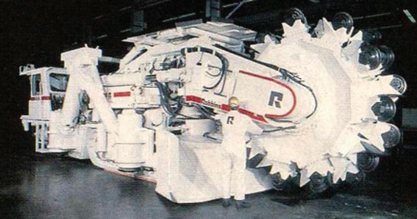
Robbins machine designed and developed to cut a rectangular profile in hard rock
Rectangular profile boring machine innovation


 Shani Wallis, TunnelTalk
Optimising the space to be excavated is a clear objective of the underground construction industry. Excavating unnecessary space is an expensive detraction from the overbreak caused by drill+blast excavation and also for TBM profiles destined for transport facilities or underground infrastructure that require flat inverts. Where the expense for drill+blast headings is in the back fill of overbreak required, for TBM headings it is for the transportation and disposal of the extra material excavated, the lining of the larger space than required and the backfilling of the invert space to create the necessary and required flat invert.
In a initiative lead by the mining industry - an industry that excavates many more kilometers of tunnel each year than the civil construction industry Robbins has developed


2022


a new hard rock mechanised excavation machine that achieves a flat invert in the first pass. The concept holds some promising prospects for underground civil engineering infrastructures that require a flat invert including networks of pedestrian passageways, networks of cable or utility pipelines, road and rail tunnels, parking complexes and many more.
If a circular, fullface rock TBM is used for the excavation, the flat floor must be created by secondary methods. These include:
• Completing a follow-on slashing operation to cut the bottom haunches of the circular profile using drill+blast or rock splitting

• Installing a precast floor deck
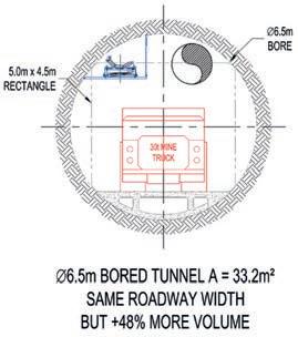
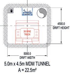
Figs 1 and 2. In comparison, a circular profile cuts up to 30% more rock to achieve a needed 5m wide x 4.5m high rectangular space
• Pouring concrete or backfilling the circular invert with crushed rock to create the floor or
• Setting a precast infill to create a space under the floor deck to house drainage pipes or operating support facilities, to help offset the penalty of over excavation to accommodate a flat road or rail deck.
These options may satisfy the need for a flat invert, but the resulting cross section is often still not the most efficient for the intended use.
In a comparison of a rectangular and a circular profile to create the same floor width of 5m, the circular profile has 30% more excavated area per lineal meter (Figs 1 and 2).
1
December
Direct by Design
New
Fig 3. New concept for rectangular hard rock excavation
Many types of rock excavation machines have been introduced over the years to cut a non-circular cross section with a flat bottom. Roadheaders have become more capable in recent years and in the 1980s, 1990s, Robbins developed its novel Mobile Miner concept. More recently different concepts with multi-partial face cutterheads on a single non-circular support frame have been trialed. Most of these however have been abandoned due to low productivity, high cutter wear, high maintenance needs, or concept limitations. If the need is for a flat invert, the most efficient excavation cross section is rectangular.
The MDM 5000 machine is based on traditional hard rock TBM concepts. It uses typical TBM disc cutters, applies forward thrust from grippers engaged against the parallel walls of the heading, has a support structure similar to an open type TBM system, and carries on it the necessary equipment to apply immediate support and carry out preexcavation injection cycles.

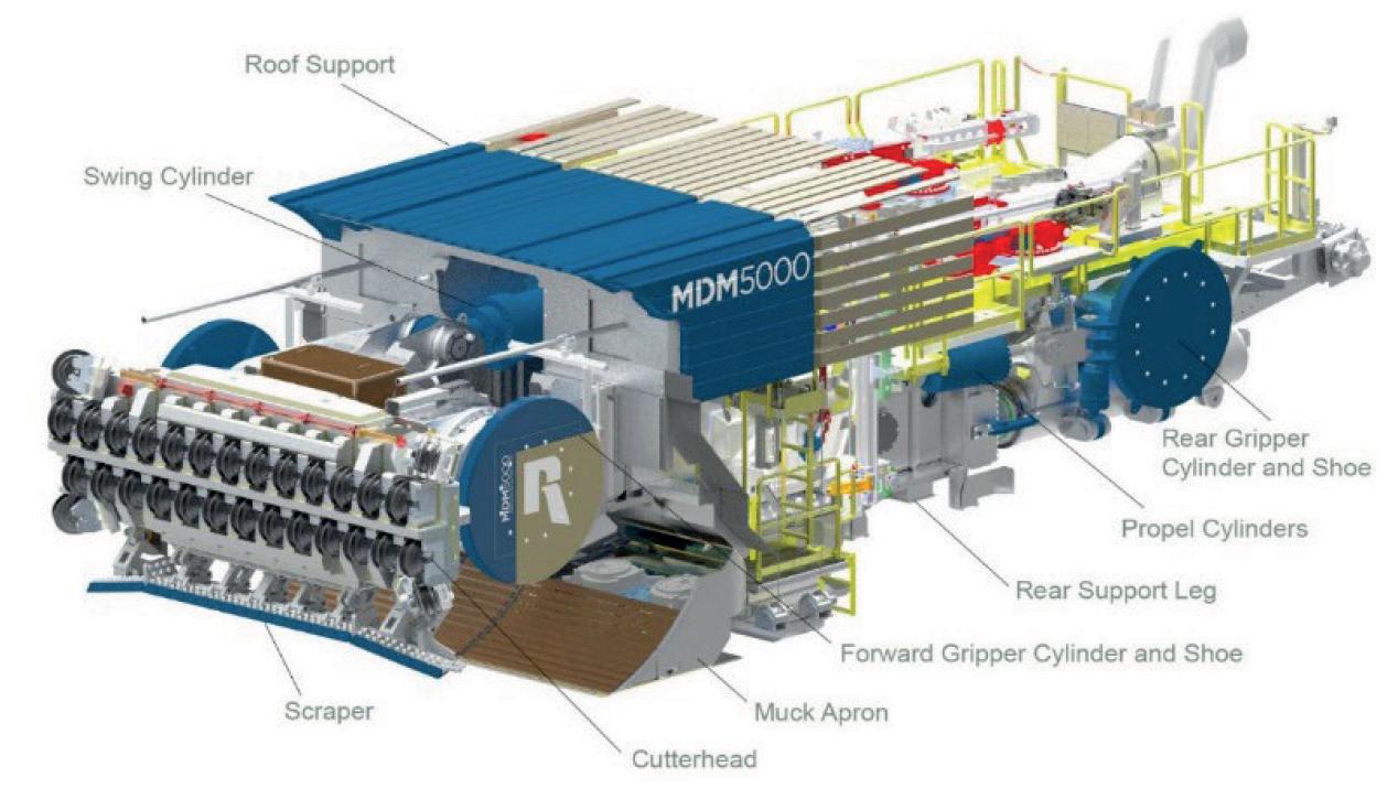
But the cutting geometry is completely different. The cutterhead is a row or bar of disc cutters that slews up and down on a horizontal axis held firmly by a robust front gripper cylinder located on this axis of rotation. This provides the stabilization and direct reaction of the cutting forces applied to the hard rock face. The grippers are anchored either side against the vertical walls of the cut profile (Fig 3).
Swinging the cutterhead about the horizontal axis allows the head to push the excavated muck rearwards and onto a muck transfer apron, much like on a roadheader but covering the full 5m width of the face. Twin loading wheels or propellers to each side of center push the muck towards the hopper in the center of the apron. A chain conveyor then pulls the muck from the hopper to the rear of the machine where a continuous haulage conveyor belt system takes over. The continuous haulage conveyor is mounted in the center of the crown and suspended by chains attached to the support pattern of roof bolts. The central position
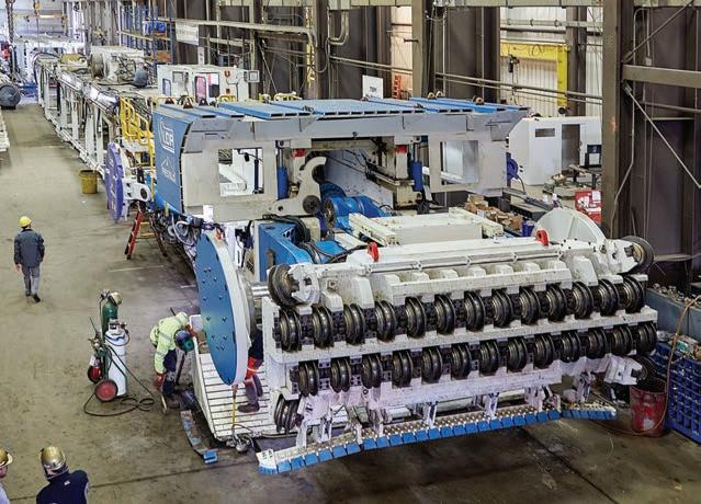
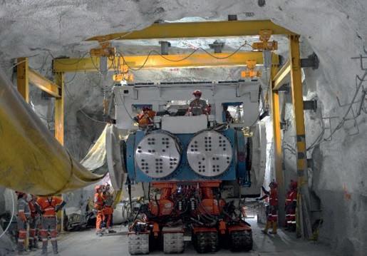
Left: Front view of the MDM showing the bar of disc cutters in the upper reach of the vertical slew, the side grippers and the muck apron; Right: Closeup of the curved face cut by two rows of 17in disc cutters
of the haulage conveyor allows it to be routed all the way forward to the discharge of the machine’s chain conveyor, doing away with the need for a separate transfer conveyor and additional transfer point.
Due to its configuration and the overhung cutterhead, the MDM is significantly frontend heavy. Counteracting the overhung weight and cutting forces results in a significant rear structure and machine length. The rear of the MDM has a main beam that mimics the main beam of a typical hard rock TBM and a rear set of grippers and thrust cylinders to advance the machine by skidding on its front fulcrum. The rear gripper and torque cylinders also provide for steering in much the same way as on a hard rock TBM.
Like other TBMs, the MDM tows a back-up system of gantries to carry power and control equipment, dust scrubber and ventilation systems, muck removal equipment, plus storage gantries for materials and supplies. It is not a lightweight, highly mobile mining machine like a roadheader or a continuous miner. It is a large machine with significant set-up and relocation times. It is a machine for longer headings at high productivity.
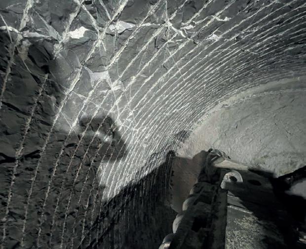
For immediate and effective rock support, the MDM, like regular TBMs, is equipped with a hydraulically operated roof shield that provides protection over the front gripper area. Wire mesh and rockbolts for support can be installed just aft of the roof shield.
Forward drill rigs drill holes for roof bolts and rear drill rigs drill the holes for bolt support of the side walls. The rear drills can also be turned forward and articulated to drill probe holes into the face, or arrays for spiling or preexcavation grouting.
Operating MDM and its performance
The first MDM machine manufactured is currently working on a project in Mexico where the concept was
developed specifically for its client, the Fresnillo silver mine. The need was for high production excavation of new roadways to develop new ore bodies.
TBMs have been used in the mining industry to achieve this purpose over the decades and most recently Robbins TBMs have been used for roadway development at the Stillwater Mine in Montana, USA, the Grosvenor coal mine to develop access drifts in Queensland, Australia, and in the 1980s to develop the spin roadway haulage system for the Selby coal mine in the UK. But their use has been limited and sporadic because the circular bore of the TBMs fail to meet the needed flat invert needed. TBMs are also difficult to mobilise and demobilise in a deep mine and they cannot easily negotiate sharp curves and steep gradients that are part of the standard mining plans.
Robbins was invited to Fresnillo by its owners to discuss plans to excavate a long 25km roadway of 5m wide to connect four ore bodies. The original thought was to bore the long tunnel with a 5m diameter hard rock TBM with a continuous conveyor system for muck haulage and a precast concrete slab to create a float roadbed. But Fresnillo remained eager to find a
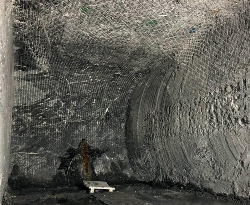
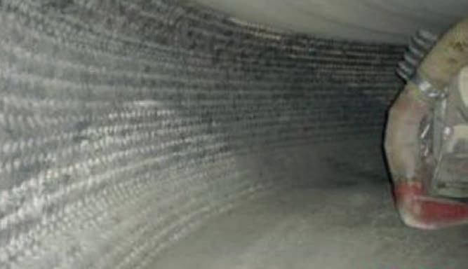
Left: Rear drill rigs for side wall bolting and drilling horizontal holes into and around the face for spiling pre-support or arrays for pre-excavation grouting; Right: Excavated MDM heading with wire mesh support across in roof and down the side walls The MDM 5000 machine gained international recognition as a Product/ Equipment Innovation Finalist in the 2022 ITA Brunel Awardsmechanical excavation tool to expedite excavation of developmental roadways with a flat invert in one pass to allow immediate use of the fleet of mine trucks and other rubber-tired equipment. Robbins and its agent Topo Machinery worked with the mine management and engineers to develop a suitable machine proposal and to provide deployment and day-to-day operation of the machine.
In addressing these needs, Robbins developed the MDM 5000, a name that stands for mine development machine and produces a rectangular cross section of 5m wide. When manufactured and delivered to site, the machine was transported from the surface to the

Innovation of its time
In the early 1980s, Robbins worked on the Mobile Miner concept in collaboration with the Mt Isa Mine in Queensland, Australia, to create the desired flat invert in a single excavation pass. The result was the MM 120- 3001. Based on the rotating wheel principle, all the disc cutters of the Mobile Miner were mounted on the circumference of a cutter wheel to attack the rock face in a drum-like fashion. The relatively thin wheel then slewed from side to side across the face from its central pivot on the body of the machine to cut a profile with a flat invert, a flat roof, a curved face and slightly curved walls.
While a machine was manufactured and put to work in the Mt Isa Mine, it failed to live up to full expectation and any further development by the mine was shelved. A significant weak point was the vulnerability of the pivot to absorb and withstand the high impact and apply the forces required for the slewing action of the cutter wheel across the face, particularly in very hard and in faulted and fractured rock.
-695m level in the mine via the existing ramp tunnel, an 8km long trip, within limited cross sections, on an undulating invert, on steep gradients, and through many sharp radius curves. The MDM was assembled as completely as possible on the surface, and transported down the ramp in three main modules: the cutterhead, the front main frame, and the rear gripper section. A special, tracked carrier was developed to transport the modules. It had multi-axis articulation so that the load could navigate obstructions in the access ramp.
At the end, a cavern only slightly larger than the 5m wide x 4.5m high dimensions of the MDM but long enough to accommodate the full MDM and backup system and
Rotation of the slewing perpendicular cutting head of the Mobile Miner excavated a rectangular profile
The concept however was never truly abandoned and there was a flurry of renewed interest in advancing the technology in the mid 2010s when mining conglomerate Rio Tinto entered into development partnerships with different manufacturers to inspire research and development of new machines.
The technology of a thin rotating wheel slewing around a central pivot but in a vertical rather than horizontal configuration is also the central
concept of modern mechanised shaft sinking machines for rock and hard rock applications. The new MDM machine by Robbins turns the concept on its side with the action of the horizontal cutter head bar of disc cutters slewing up and down vertically across the face with the ability to apply more force and absorb more cutter impact.
Reference
• Robbins Mobile Miner squares up to the task – TunnelTalk, Nov 1987
4
Left: Cutterhead module on the tracked transport carrier for the journey down the 8km long access ramp Right: Main frame module on transport crawlers arriving in the assembly chamber
5
History of mine development innovation
Fresnillo is one of the world’s oldest continuously operating mines and has been in operation for almost five centuries. The mine has a long history of embracing new technology. In 1838, an original Watts steam engine was brought from England to Mexico, skidded overland by teams of oxen and installed at the mine to provide dewatering. The engine is still displayed at the mine, proudly showcasing the mine’s heritage.
In efforts to develop new technology to provide Fresnillo with high excavation production and a flat invert, Robbins looked back to an earlier development by long time Robbins engineers John Gibson and Andy Anderson, who formed a new company after retirement and developed the Reef Mole. The machine was developed, built and worked in a platinum mine in South Africa to cut 1m high x 5m wide rectangular headings to follow the ore seam.
The cutting action was performed by a swinging, rather than a
rotating cutterhead, that was swung horizontally by hydraulic cylinders, to create the rectangular cut. Strong grippers locked the machine within the excavated reef to resist the significant cutting forces. The geometry of the machine was arranged so that the cutters swept across the semi-circular shaped face with nearly constant penetration to provide the most effective cutting action. A vacuum system removed the cut ore.
The Reef Mole cut effectively in the very hard rock of the platinum reef, but the machine was regarded as experimental by the mine and did not get priority for resources such as power, water, ventilation, haulage, and personnel - all of which are precious commodities in a deep operating mine. Though promising, the Reef Mole was never fully utilized by the mine and fell away due to lack on R&D attention and resource, until reviewed by Robbins at the start of the MDM development.
Face of a Reef Mole mining machine heading
the towed continuous conveyor payout cassette was excavated for assembly and launch of the machine. A local niche was cut into the crown to accommodate a manual hoist to lift on the roof shield, drills, and other appurtenant pieces.
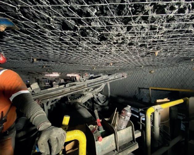
The MDM began work in late 2019, boring through geological conditions that comprise andesites and shales with quartz intrusions. The quartz intrusions defeated earlier attempts to excavate the roadways with heavy roadheaders. Support wire mesh was brought to the front of the machine in rolls long enough to cover the width of the roof, and down each side to about springline. The mesh rolls were 1.4m wide to provide overlap at each row of roof bolts. Roof bolt spacing was 1.24m to provide effective support in the anticipated conditions and corresponded to the spacing for the continuous haulage conveyor hanger chains.
After overcoming some early teething problems, the machine has produced a finished supported rectangular roadway at an average rate of 150m/month. As it has progressed the machine has successfully passed through zones of unstable ground and high inflows of water. Through zones of faulted rock, other traditional mining methods were also used to augment the MDM ground support capabilities.
As of July 2021, the MDM machine had excavated about 1.7km of 5m wide x 4.5m high roadway with better safety, greater consistency, and a finished roadway in one
pass. This exceeds drill+blast roadway excavation by a favorable margin.
In overall observation, comparisons with traditional, full face circular TBMs must be evaluated carefully. While there are still many benefits offered by the MDM, most prominently a flat roadbed, the cyclic, swinging action of the cutting head, the machine has lower productivity. The MDM is also not the lightweight, mobile rock excavation machine that the industry also now covets. Such a lightweight machine may be possible, and development will surely be undertaken due to the industry demands but such a machine will for sure have the penalty of decreased productivity.
For this advance in mechanized excavation innovation, the MDM is a high powered machine that tows its own support system and cute the rectangular profile that the client wants at better productivity, and under safer working conditions. n
TunnelTalk References
• Robbins Mobile Miner squares up to the task - Nov 1987
• TBM first for Australian coal seam access - Nov 2013
• TBM success signals coal access opportunity - Sep 2014
• TBMs versus roadheaders: an investment in speed at the Selby coal mine – UK Special Edition p37
6