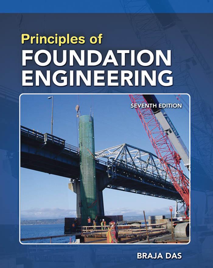
Principles of Foundation Engineering, SI
Seventh Edition
BRAJA M. DAS
Principles of Foundation Engineering, SI
Seventh Edition
Author Braja M. Das
Publisher, Global Engineering: Christopher M. Shortt
Senior Developmental Editor: Hilda Gowans
Editorial Assistant: Tanya Altieri
Team Assistant: Carly Rizzo
Marketing Manager: Lauren Betsos
Production Manager: Patricia M. Boies
Content Project Manager: Darrell Frye
Production Service: RPK Editorial Services, Inc.
Copyeditor: Shelly Gerger-Knecthl
Proofreader: Martha McMaster
Indexer: Braja M. Das
Compositor: Integra
Senior Art Director: Michelle Kunkler
Internal Designer: Carmela Pereira
Cover Designer: Andrew Adams
Cover Images:
Courtesy of ADSC : The International Association of Foundation Drillers, Dallas, Texas
D. B. M. Contractors, Inc., Federal Way, Washington
Image Permissions Researcher: Deanna Ettinger
Text Permissions Researcher: Katie Huha
Text and Image Permissions Researcher: Kristiina Paul
First Print Buyer: Arethea Thomas
©2011,2007 Cengage Learning
ALL RIGHTS RESERVED. No part of this work covered by the copyright herein may be reproduced, transmitted, stored, or used in any form or by any means graphic, electronic, or mechanical, including but not limited to photocopying, recording, scanning, digitizing, taping, web distribution, information networks, or information storage and retrieval systems, except as permitted under Section 107 or 108 of the 1976 United States Copyright Act, without the prior written permission of the publisher.
For product information and technology assistance, contact us at Cengage Learning Customer & Sales Support, 1-800-354-9706
For permission to use material from this text or product, submit all requests online at cengage.com/permissions Further permissions questions can be emailed to permissionrequest@cengage.com
Library of Congress Control Number: 2010922634
ISBN-13:978-0-495-66812-1
ISBN-10:0-495-66812-5
Cengage Learning
200 First Stamford Place, Suite 400 Stamford, CT 06902 USA
Cengage Learning is a leading provider of customized learning solutions with office locations around the globe, including Singapore, the United Kingdom, Australia, Mexico, Brazil, and Japan. Locate your local office at: international.cengage.com/region
Cengage Learning products are represented in Canada by Nelson Education Ltd.
For your course and learning solutions, visit www.cengage.com/engineering
Purchase any of our products at your local college store or at our preferred online store www.CengageBrain.com
To our granddaughter, Elizabeth Madison
This page intentionally left blank
This page intentionally left blank
This page intentionally left blank
1 Geotechnical Properties of Soil1
1.1 Introduction1
1.2 Grain-Size Distribution2
1.3 Size Limits for Soils5
1.4 Weight–Volume Relationships5
1.5 Relative Density10
1.6 Atterberg Limits15
1.7 Liquidity Index16
1.8 Activity17
1.9 Soil Classification Systems17
1.10 Hydraulic Conductivity of Soil25
1.11 Steady-State Seepage28
1.12 Effective Stress30
1.13 Consolidation32
1.14 Calculation of Primary Consolidation Settlement37
1.15 Time Rate of Consolidation38
1.16 Degree of Consolidation Under Ramp Loading44
1.17 Shear Strength47
1.18 Unconfined Compression Test52
References62 f r
1.19 Comments on Friction Angle,54
1.20 Correlations for Undrained Shear Strength, Cu 57
1.21 Sensitivity57
Problems58
2 Natural Soil Deposits and Subsoil Exploration64
2.1 Introduction64
Natural Soil Deposits 64
2.2 Soil Origin64
2.3 Residual Soil66
2.4 Gravity Transported Soil67
2.5 Alluvial Deposits68
2.6 Lacustrine Deposits70
2.7 Glacial Deposits70
2.8 Aeolian Soil Deposits71
2.9 Organic Soil73
2.10 Some Local Terms for Soils73
Subsurface Exploration 74
2.11 Purpose of Subsurface Exploration74
2.12 Subsurface Exploration Program74
2.13 Exploratory Borings in the Field77
2.14 Procedures for Sampling Soil81
2.15 Split-Spoon Sampling81
2.16 Sampling with a Scraper Bucket89
2.17 Sampling with a Thin-Walled Tube90
2.18 Sampling with a Piston Sampler92
2.19 Observation of Water Tables92
2.20 Vane Shear Test94
2.21 Cone Penetration Test98
2.22 Pressuremeter Test (PMT)107
2.23 Dilatometer Test110
2.24 Coring of Rocks113
2.25 Preparation of Boring Logs117
2.26 Geophysical Exploration118
2.27 Subsoil Exploration Report126 Problems126 References130
3 Shallow Foundations: Ultimate Bearing Capacity133
3.1 Introduction133
3.2 General Concept133
3.3 Terzaghi’s Bearing Capacity Theory136
3.4 Factor of Safety140
3.5 Modification of Bearing Capacity Equations for Water Table142
3.6 The General Bearing Capacity Equation143
3.7 Case Studies on Ultimate Bearing Capacity 148
3.8 Effect of Soil Compressibility153
3.9 Eccentrically Loaded Foundations157
3.10 Ultimate Bearing Capacity under Eccentric Loading—One-Way Eccentricity159
3.11 Bearing Capacity—Two-way Eccentricity165
3.12 Bearing Capacity of a Continuous Foundation Subjected to Eccentric Inclined Loading173
Problems177
References179
4
Ultimate Bearing Capacity of Shallow Foundations: Special Cases181
4.1 Introduction181
4.2 Foundation Supported by a Soil with a Rigid Base at Shallow Depth181
4.3 Bearing Capacity of Layered Soils:Stronger Soil Underlain by Weaker Soil190
4.4 Bearing Capacity of Layered Soil:Weaker Soil Underlain by Stronger Soil198
4.5 Closely Spaced Foundations—Effect on Ultimate Bearing Capacity200
4.6 Bearing Capacity of Foundations on Top of a Slope203
4.7 Seismic Bearing Capacity of a Foundation at the Edge of a Granular Soil Slope209
4.8 Bearing Capacity of Foundations on a Slope210
4.9 Foundations on Rock212
4.10 Uplift Capacity of Foundations213
Problems219
References221
5 Shallow Foundations: Allowable Bearing Capacity and Settlement223
5.1 Introduction223
Vertical Stress Increase in a Soil Mass Caused by Foundation Load 224
5.2 Stress Due to a Concentrated Load224
5.3 Stress Due to a Circularly Loaded Area224
5.4 Stress below a Rectangular Area226
5.5 Average Vertical Stress Increase Due to a Rectangularly Loaded Area232
5.6 Stress Increase under an Embankment236
5.7 Westergaard’s Solution for Vertical Stress Due to a Point Load240
5.8 Stress Distribution for Westergaard Material241
Elastic Settlement 243
5.9 Elastic Settlement of Foundations on Saturated Clay ( S 0.5)243
5.10 Settlement Based on the Theory of Elasticity245
5.11 Improved Equation for Elastic Settlement254
5.12 Settlement of Sandy Soil:Use of Strain Influence Factor258
5.13 Settlement of Foundation on Sand Based on Standard Penetration Resistance263
5.14 Settlement in Granular Soil Based on Pressuremeter Test (PMT)267
Consolidation Settlement 273
5.15 Primary Consolidation Settlement Relationships273
5.16 Three-Dimensional Effect on Primary Consolidation Settlement274
5.17 Settlement Due to Secondary Consolidation278
5.18 Field Load Test280
5.19 Presumptive Bearing Capacity282
5.20 Tolerable Settlement of Buildings283 Problems285 References288
6 Mat Foundations291
6.1 Introduction291
6.2 Combined Footings291
6.3 Common Types of Mat Foundations294
6.4 Bearing Capacity of Mat Foundations296
6.5 Differential Settlement of Mats299
6.6 Field Settlement Observations for Mat Foundations300
6.7 Compensated Foundation300
6.8 Structural Design of Mat Foundations304 Problems322 References323
7 Lateral Earth Pressure324
7.1 Introduction324
7.2 Lateral Earth Pressure at Rest325
Active Pressure 328
7.3 Rankine Active Earth Pressure328
7.4 A Generalized Case for Rankine Active Pressure334
7.5 Coulomb’s Active Earth Pressure340
7.6 Active Earth Pressure Due to Surcharge348
7.7 Active Earth Pressure for Earthquake Conditions350
7.8 Active Pressure for Wall Rotation about the Top:Braced Cut355
7.9 Active Earth Pressure for Translation of Retaining Wall—Granular Backfill357
Passive Pressure 360
7.10 Rankine Passive Earth Pressure360
7.11 Rankine Passive Earth Pressure:Vertical Backface and Inclined Backfill363
7.12 Coulomb’s Passive Earth Pressure365
7.13 Comments on the Failure Surface Assumption for Coulomb’s Pressure Calculations366
7.14 Passive Pressure under Earthquake Conditions370 Problems371
References373
8 Retaining Walls375
8.1 Introduction375
Gravity and Cantilever Walls 377
8.2 Proportioning Retaining Walls377
8.3 Application of Lateral Earth Pressure Theories to Design378
8.4 Stability of Retaining Walls380
8.5 Check for Overturning382
8.6 Check for Sliding along the Base384
8.7 Check for Bearing Capacity Failure387
8.8 Construction Joints and Drainage from Backfill396
8.9 Gravity Retaining-Wall Design for Earthquake Conditions399
8.10 Comments on Design of Retaining Walls and a Case Study402
Mechanically Stabilized Retaining Walls 405
8.11 Soil Reinforcement405
8.12 Considerations in Soil Reinforcement406
8.13 General Design Considerations409
8.14 Retaining Walls with Metallic Strip Reinforcement410
8.15 Step-by-Step-Design Procedure Using Metallic Strip Reinforcement417
8.16 Retaining Walls with Geotextile Reinforcement422
8.17 Retaining Walls with Geogrid Reinforcement—General428
8.18 Design Procedure fore Geogrid-Reinforced Retaining Wall428
Problems433
References435
9 Sheet Pile Walls437
9.1 Introduction437
9.2 Construction Methods441
9.3 Cantilever Sheet Pile Walls442
9.4 Cantilever Sheet Piling Penetrating Sandy Soils442
9.5 Special Cases for Cantilever Walls Penetrating a Sandy Soil449
9.6 Cantilever Sheet Piling Penetrating Clay452
9.7 Special Cases for Cantilever Walls Penetrating Clay457
9.8 Anchored Sheet-Pile Walls460
9.9 Free Earth Support Method for Penetration of Sandy Soil461
9.10 Design Charts for Free Earth Support Method (Penetration into Sandy Soil)465
9.11 Moment Reduction for Anchored Sheet-Pile Walls469
9.12 Computational Pressure Diagram Method for Penetration into Sandy Soil472
9.13 Fixed Earth-Support Method for Penetration into Sandy Soil476
9.14 Field Observations for Anchor Sheet Pile Walls479
9.15 Free Earth Support Method for Penetration of Clay482
9.16 Anchors486
9.17 Holding Capacity of Anchor Plates in Sand488
9.18 Holding Capacity of Anchor Plates in Clay (Condition)495
References500 f5 0
9.19 Ultimate Resistance of Tiebacks495
Problems497
10 Braced Cuts501
10.1 Introduction501
10.2 Pressure Envelope for Braced-Cut Design502
10.3 Pressure Envelope for Cuts in Layered Soil506
10.4 Design of Various Components of a Braced Cut507
10.5 Case Studies of Braced Cuts515
10.6 Bottom Heave of a Cut in Clay520
10.7 Stability of the Bottom of a Cut in Sand524
10.8 Lateral Yielding of Sheet Piles and Ground Settlement529
Problems531
References533
11 Pile Foundations535
11.1 Introduction535
11.2 Types of Piles and Their Structural Characteristics537
11.3 Estimating Pile Length546
11.4 Installation of Piles548
11.5 Load Transfer Mechanism551
11.6 Equations for Estimating Pile Capacity554
11.7 Meyerhof’s Method for Estimating Qp 557
11.8 Vesic’s Method for Estimating Qp 560
11.9 Coyle and Castello’s Method for Estimating Qp in Sand563
11.10 Correlations for Calculating Qp with SPT and CPT Results567
11.11 Frictional Resistance (Qs) in Sand568
11.12 Frictional (Skin) Resistance in Clay575
11.13 Point Bearing Capacity of Piles Resting on Rock579
11.14 Pile Load Tests583
11.15 Elastic Settlement of Piles588
11.16 Laterally Loaded Piles591
11.17 Pile-Driving Formulas606
11.18 Pile Capacity For Vibration-Driven Piles611
11.19 Negative Skin Friction613
Group Piles 617
11.20 Group Efficiency617
11.21 Ultimate Capacity of Group Piles in Saturated Clay621
11.22 Elastic Settlement of Group Piles624
11.23 Consolidation Settlement of Group Piles626
11.24 Piles in Rock629 Problems629 References634
12 Drilled-Shaft Foundations637
12.1 Introduction637
12.2 Types of Drilled Shafts638
12.3 Construction Procedures639
12.4 Other Design Considerations645
12.5 Load Transfer Mechanism646
12.6 Estimation of Load-Bearing Capacity646
12.7 Drilled Shafts in Granular Soil:Load-Bearing Capacity648
12.8 Load-Bearing Capacity Based on Settlement652
12.9 Drilled Shafts in Clay:Load-Bearing Capacity661
12.10 Load-Bearing Capacity Based on Settlement663
12.11 Settlement of Drilled Shafts at Working Load668
12.12 Lateral Load-Carrying Capacity—Characteristic Load and Moment Method670
12.13 Drilled Shafts Extending into Rock679 Problems681 References685
13 Foundations on Difficult Soils686
13.1 Introduction686
Collapsible Soil 686
13.2 Definition and Types of Collapsible Soil686
13.3 Physical Parameters for Identification687
13.4 Procedure for Calculating Collapse Settlement691
13.5 Foundation Design in Soils Not Susceptible to Wetting692
13.6 Foundation Design in Soils Susceptible to Wetting694
Expansive Soils 695
13.7 General Nature of Expansive Soils695
13.8 Unrestrained Swell Test699
13.9 Swelling Pressure Test700
13.10 Classification of Expansive Soil on the Basis of Index Tests705
13.11 Foundation Considerations for Expansive Soils708
13.12 Construction on Expansive Soils711
Sanitary Landfills 716
13.13 General Nature of Sanitary Landfills716
13.14 Settlement of Sanitary Landfills717 Problems719 References720
14 Soil Improvement and Ground Modification722
14.1 Introduction722
14.2 General Principles of Compaction723
14.3 Field Compaction727
14.4 Compaction Control for Clay Hydraulic Barriers730
14.5 Vibroflotation732
14.6 Blasting739
14.7 Precompression739
14.8 Sand Drains745
14.9 Prefabricated Vertical Drains756
14.10 Lime Stabilization760
14.11 Cement Stabilization764
14.12 Fly-Ash Stabilization766
14.13 Stone Columns767
14.14 Sand Compaction Piles772
14.15 Dynamic Compaction774
14.16 Jet Grouting776 Problems778 References781 Answers
Preface
Soil mechanics and foundation engineering have developed rapidly during the last fifty years. Intensive research and observation in the field and the laboratory have refined and improved the science of foundation design. Originally published in the fall of 1983 with a 1984 copyright,this text on the principles of foundation engineering is now in the seventh edition. The use of this text throughout the world has increased greatly over the years; it also has been translated into several languages. New and improved materials that have been published in various geotechnical engineering journals and conference proceedings have been incorporated into each edition of the text.
Principles of Foundation Engineering is intended primarily for undergraduate civil engineering students. The first chapter,on Geotechnical Properties of Soil,reviews the topics covered in the introductory soil mechanics course,which is a prerequisite for the foundation engineering course. The text is composed of fourteen chapters with examples and problems,and an answer section for selected problems. The chapters are mostly devoted to the geotechnical aspects of foundation design. Both Systéime International (SI) units and English units are used in the text.
Because the text introduces the application of fundamental concepts of foundation analysis and design to civil engineering students,the mathematical derivations are not always presented; instead,just the final form of the equation is given. A list of references for further information and study is included at the end of each chapter.
Each chapter contains many example problems that will help students understand the application of the equations and graphs. For better understanding and visualization of the ideas and field practices,about thirty new photographs have been added in this edition.
A number of practice problems also are given at the end of each chapter. Answers to some of these problems are given at the end of the text.
The following is a brief overview of the changes from the sixth edition.
• In several parts of the text,the presentation has been thoroughly reorganized for better understanding.
• A number of new case studies have been added to familiarize students with the deviations from theory to practice.
• In Chapter 1 on Geotechnical Properties of Soil,new sections on liquidity index and activity have been added. The discussions on hydraulic conductivity of clay,relative density,and the friction angle of granular soils have been expanded.
• Expanded treatment of the weathering process of rocks is given in Chapter 2,Natural Soil Deposits and Subsoil Exploration.
• In Chapter 3 (Shallow Foundations:Ultimate Bearing Capacity),a new case study on bearing capacity failure in soft saturated clay has been added. Also included is the reduction factor method for estimating the ultimate bearing capacity of eccentrically loaded strip foundations on granular soil.
• Chapter 4,Ultimate Bearing Capacity of Shallow Foundations:Special Cases,has new sections on the ultimate bearing capacity of weaker soil underlain by a stronger soil,the seismic bearing capacity of foundations at the edge of a granular slope, foundations on rocks,and the stress characteristics solution for foundations located on the top of granular slopes.
• Stress distribution due to a point load and uniformly loaded circular and rectangular areas located on the surface of a Westergaard-type material has been added to Chapter 5 on Allowable Bearing Capacity and Settlement. Also included in this chapter is the procedure to estimate foundation settlement based on Pressuremeter test results.
• Lateral earth pressure due to a surcharge on unyielding retaining structures is now included in Chapter 7 (Lateral Earth Pressure). Also included in this chapter is the solution for passive earth pressure on a retaining wall with inclined back face and horizontal granular backfill using the method of triangular slices.
• Chapter 8 on Retaining Walls has a new case study. A more detailed discussion is provided on the design procedure for geogrid-reinforced retaining walls.
• Chapter 9 on Sheet Pile Walls has an added section on the holding capacity of plate anchors based on the stress characteristics solution.
• Two case studies have been added to the chapter on Braced Cuts (Chapter 10).
• The chapter on Pile Foundations (Chapter 11) has been thoroughly reorganized for better understanding.
• Based on recent publications,new recommendations have been made to estimate the load-bearing capacity of drilled shafts extending to rock (Chapter 12).
As my colleagues in the geotechnical engineering area well know,foundation analysis and design is not just a matter of using theories,equations and graphs from a textbook. Soil profiles found in nature are seldom homogeneous,elastic,and isotropic. The educated judgment needed to properly apply the theories,equations,and graphs to the evaluation of soils,foundations,and foundation design cannot be overemphasized or completely taught in the classroom. Field experience must supplement classroom work.
The following individuals were kind enough to share their photographs which have been included in this new edition.
• Professor A. S. Wayal,K. J. Somayia Polytechnic,Mumbai,India
• Professor Sanjeev Kumar,Southern Illinois University,Carbondale,Illinois
• Mr. Paul J. Koszarek,Professional Service Industries,Inc.,Waukesha,Wisconsin
• Professor Khaled Sobhan,Florida Atlantic University,Boca Raton,Florida
• Professor Jean-Louis Briaud,Texas A&M University,College Station,Texas
• Dr. Dharma Shakya,Geotechnical Solutions,Inc.,Irvine,California
• Mr. Jon Ridgeway,Tensar International,Atlanta,Georgia
• Professor N. Sivakugan,James Cook University,Townsville,Queensland,Australia
• Professor Anand J. Puppala,University of Texas at Arlington,Arlington,Texas
• Professor Thomas M. Petry,Missouri University of Science and Technology, Rolla,Missouri
Thanks are due to Neill Belk,graduate student at the University of North Carolina at Charlotte,and Jennifer Nicks,graduate student at Texas A&M University,College Station, Texas,for their help during the preparation of this revised edition. I am also grateful for several helpful suggestions of Professor Adel S. Saada of Case Western Reserve University, Cleveland,Ohio.
Thanks are due to Chris Carson,Executive Director,Global Publishing Program; and Hilda Gowans,Senior Developmental Editor,Engineering,Cengage Learning; Lauren Betsos,Marketing Manager; and Rose Kernan of RPK Editorial Services for their interest and patience during the revision and production of the manuscript.
For the past twenty-seven years,my primary source of inspiration has been the immeasurable energy of my wife,Janice. I am grateful for her continual help in the development of the original text and its six subsequent revisions.
Braja M. Das
Geotechnical Properties of Soil
1.1 Introduction
The design of foundations of structures such as buildings,bridges,and dams generally requires a knowledge of such factors as (a) the load that will be transmitted by the superstructure to the foundation system,(b) the requirements of the local building code,(c) the behavior and stress-related deformability of soils that will support the foundation system, and (d) the geological conditions of the soil under consideration. To a foundation engineer, the last two factors are extremely important because they concern soil mechanics.
The geotechnical properties of a soil—such as its grain-size distribution,plasticity, compressibility,and shear strength—can be assessed by proper laboratory testing. In addition,recently emphasis has been placed on the in situ determination of strength and deformation properties of soil,because this process avoids disturbing samples during field exploration. However,under certain circumstances,not all of the needed parameters can be or are determined,because of economic or other reasons. In such cases,the engineer must make certain assumptions regarding the properties of the soil. To assess the accuracy of soil parameters—whether they were determined in the laboratory and the field or whether they were assumed—the engineer must have a good grasp of the basic principles of soil mechanics. At the same time,he or she must realize that the natural soil deposits on which foundations are constructed are not homogeneous in most cases. Thus,the engineer must have a thorough understanding of the geology of the area—that is,the origin and nature of soil stratification and also the groundwater conditions. Foundation engineering is a clever combination of soil mechanics,engineering geology,and proper judgment derived from past experience. To a certain extent,it may be called an art.
When determining which foundation is the most economical,the engineer must consider the superstructure load,the subsoil conditions,and the desired tolerable settlement. In general,foundations of buildings and bridges may be divided into two major categories: (1) shallow foundations and (2) deep foundations. Spread footings,wall footings, and mat foundations are all shallow foundations. In most shallow foundations, the depth of embedment can be equal to or less than three to four times the width of the foundation. Pile and drilled shaft foundations are deep foundations. They are used when top layers have poor
load-bearing capacity and when the use of shallow foundations will cause considerable structural damage or instability. The problems relating to shallow foundations and mat foundations are considered in Chapters 3,4,5,and 6. Chapter 11 discusses pile foundations,and Chapter 12 examines drilled shafts.
This chapter serves primarily as a review of the basic geotechnical properties of soils. It includes topics such as grain-size distribution,plasticity,soil classification,effective stress, consolidation,and shear strength parameters. It is based on the assumption that you have already been exposed to these concepts in a basic soil mechanics course.
1.2
Grain-Size Distribution
In any soil mass,the sizes of the grains vary greatly. To classify a soil properly,you must know its grain-size distribution. The grain-size distribution of coarse-grained soil is generally determined by means of sieve analysis. For a fine-grained soil,the grain-size distribution can be obtained by means of hydrometer analysis. The fundamental features of these analyses are presented in this section. For detailed descriptions,see any soil mechanics laboratory manual (e.g.,Das,2009).
Sieve Analysis
A sieve analysis is conducted by taking a measured amount of dry,well-pulverized soil and passing it through a stack of progressively finer sieves with a pan at the bottom. The amount of soil retained on each sieve is measured,and the cumulative percentage of soil passing through each is determined. This percentage is generally referred to as percent finer. Table 1.1 contains a list of U.S. sieve numbers and the corresponding size of their openings. These sieves are commonly used for the analysis of soil for classification purposes.
Table 1.1 U.S. Standard Sieve Sizes
size, D (mm)
Figure 1.1 Grain-size distribution curve of a coarse-grained soil obtained from sieve analysis
The percent finer for each sieve,determined by a sieve analysis,is plotted on semilogarithmic graph paper, as shown in Figure 1.1. Note that the grain diameter, D, is plotted on the logarithmic scale and the percent finer is plotted on the arithmetic scale.
Two parameters can be determined from the grain-size distribution curves of coarsegrained soils:(1) the uniformity coefficient and (2) the coefficient of gradation, or coefficient of curvature These coefficients are
where and are the diameters corresponding to percents finer than 10,30,and 60%,respectively.
For the grain-size distribution curve shown in Figure 1.1, and Thus,the values of and are and
Parameters and are used in the Unified Soil Classification System, which is described later in the chapter.
Hydrometer Analysis
Hydrometer analysis is based on the principle of sedimentation of soil particles in water. This test involves the use of 50 grams of dry,pulverized soil. A deflocculating agent is always added to the soil. The most common deflocculating agent used for hydrometer analysis is 125 cc of 4% solution of sodium hexametaphosphate. The soil is allowed to soak for at least 16 hours in the deflocculating agent. After the soaking period,distilled water is added,and the soil–deflocculating agent mixture is thoroughly agitated. The sample is then transferred to a 1000-ml glass cylinder. More distilled water is added to the cylinder to fill it to the 1000-ml mark,and then the mixture is again thoroughly agitated. A hydrometer is placed in the cylinder to measure the specific gravity of the soil–water suspension in the vicinity of the instrument’s bulb (Figure 1.2),usually over a 24-hour period. Hydrometers are calibrated to show the amount of soil that is still in suspension at any given time t. The largest diameter of the soil particles still in suspension at time t can be determined by Stokes’law,
(1.3)
Gs 5 specific D 5 diameter
where of the soil particle gravity of soil solids of water h5 viscosity
Figure 1.2 Hydrometer analysis
weight of water
effective length (i.e.,length measured from the water surface in the cylinder to the center of gravity of the hydrometer; see Figure 1.2)
Soil particles having diameters larger than those calculated by Eq. (1.3) would have settled beyond the zone of measurement. In this manner,with hydrometer readings taken at various times,the soil percent finer than a given diameter D can be calculated and a grain-size distribution plot prepared. The sieve and hydrometer techniques may be combined for a soil having both coarse-grained and fine-grained soil constituents.
1.3 Size Limits for Soils
Several organizations have attempted to develop the size limits for gravel,sand,silt, and clay on the basis of the grain sizes present in soils. Table 1.2 presents the size limits recommended by the American Association of State Highway and Transportation Officials (AASHTO) and the Unified Soil Classification systems (Corps of Engineers,Department of the Army,and Bureau of Reclamation). The table shows that soil particles smaller than 0.002 mm have been classified as clay. However,clays by nature are cohesive and can be rolled into a thread when moist. This property is caused by the presence of clay minerals such as kaolinite,illite, and montmorillonite. In contrast,some minerals,such as quartz and feldspar, may be present in a soil in particle sizes as small as clay minerals,but these particles will not have the cohesive property of clay minerals. Hence,they are called claysize particles, not clay particles.
1.4
Weight–Volume Relationships
In nature,soils are three-phase systems consisting of solid soil particles,water,and air (or gas). To develop the weight–volume relationships for a soil,the three phases can be separated as shown in Figure 1.3a. Based on this separation,the volume relationships can then be defined.
The void ratio,e, is the ratio of the volume of voids to the volume of soil solids in a given soil mass,or
Table 1.2 Soil-Separate Size Limits
Classification system Grain size (mm)
Unified
AASHTO
Gravel:75 mm to 4.75 mm
Sand:4.75 mm to 0.075 mm
Silt and clay (fines):mm
Gravel:75 mm to 2 mm
Sand:2 mm to 0.05 mm
Silt:0.05 mm to 0.002 mm
Clay:mm ,0.002 ,0.075
(b) Unsaturated soil; Vs = 1
Note:
Sat
Figure 1.3 Weight–volume relationships where of voids of soil solids
The porosity,n, is the ratio of the volume of voids to the volume of the soil specimen,or (1.5) where
Moreover,
The degree of saturation,S, is the ratio of the volume of water in the void spaces to the volume of voids,generally expressed as a percentage,or
where of water
Note that,for saturated soils,the degree of saturation is 100%.
The weight relationships are moisture content,moist unit weight,dry unit weight, and saturated unit weight, often defined as follows:
where of the soil solids of water
where weight of the soil
The weight of air,in the soil mass is assumed to be negligible. (1.10)
When a soil mass is completely saturated (i.e.,all the void volume is occupied by water),the moist unit weight of a soil [Eq. (1.9)] becomes equal to the saturated unit weight So if
More useful relations can now be developed by considering a representative soil specimen in which the volume of soil solids is equal to unity, as shown in Figure 1.3b. Note that if then,from Eq. (1.4),and the weight of the soil solids is where
