
www.durlon.com
info@durlon.com


www.durlon.com
info@durlon.com
Evolution isn’t a choice in today’s business landscape, it’s the only way to succeed.
Progress relies on everything moving forward; from people to machinery to production. Everything must flow.
As we engineer our way to a better world, we are breaking down barriers, making sure each process is in place, always reflecting and improving. We are experts at delivering the best sealing solutions to help our customers unlock their highest potential.
Our global community of industry leading specialists drive our innovative production and materials to consistently raise the bar.
Whether through the stress of everyday use, or specialized applications and hightemperature environments, liquid or gas, our products deliver sustainable integrity.
At Durlon®, we succeed when you succeed.
The basic principle of power generation involves the conversion of energy from one form to another. In electrical power generation, energy is converted from mechanical energy (such as the rotation of a turbine) to electrical energy (by the rotation of a generator). The mechanical energy is usually generated by the combustion of fossil fuels or by harnessing the power of water, wind, or sunlight.
The process of power generation varies depending on the source of energy being used. For example, in fossil fuel power plants, the fuel is burned to heat water, producing steam that drives a turbine, which in turn rotates a generator to produce electricity. In nuclear power plants, the heat is produced by nuclear fission, which is used to produce steam to turn the turbine.
Renewable energy sources like wind and solar power use the power of natural forces to produce electricity. In a wind power plant, wind turbines are used to generate mechanical energy, which is then converted into electrical energy. Similarly, in solar power plants, photovoltaic cells convert sunlight into electrical energy.
Following is a more detailed explanation of each of the various types of power generation:
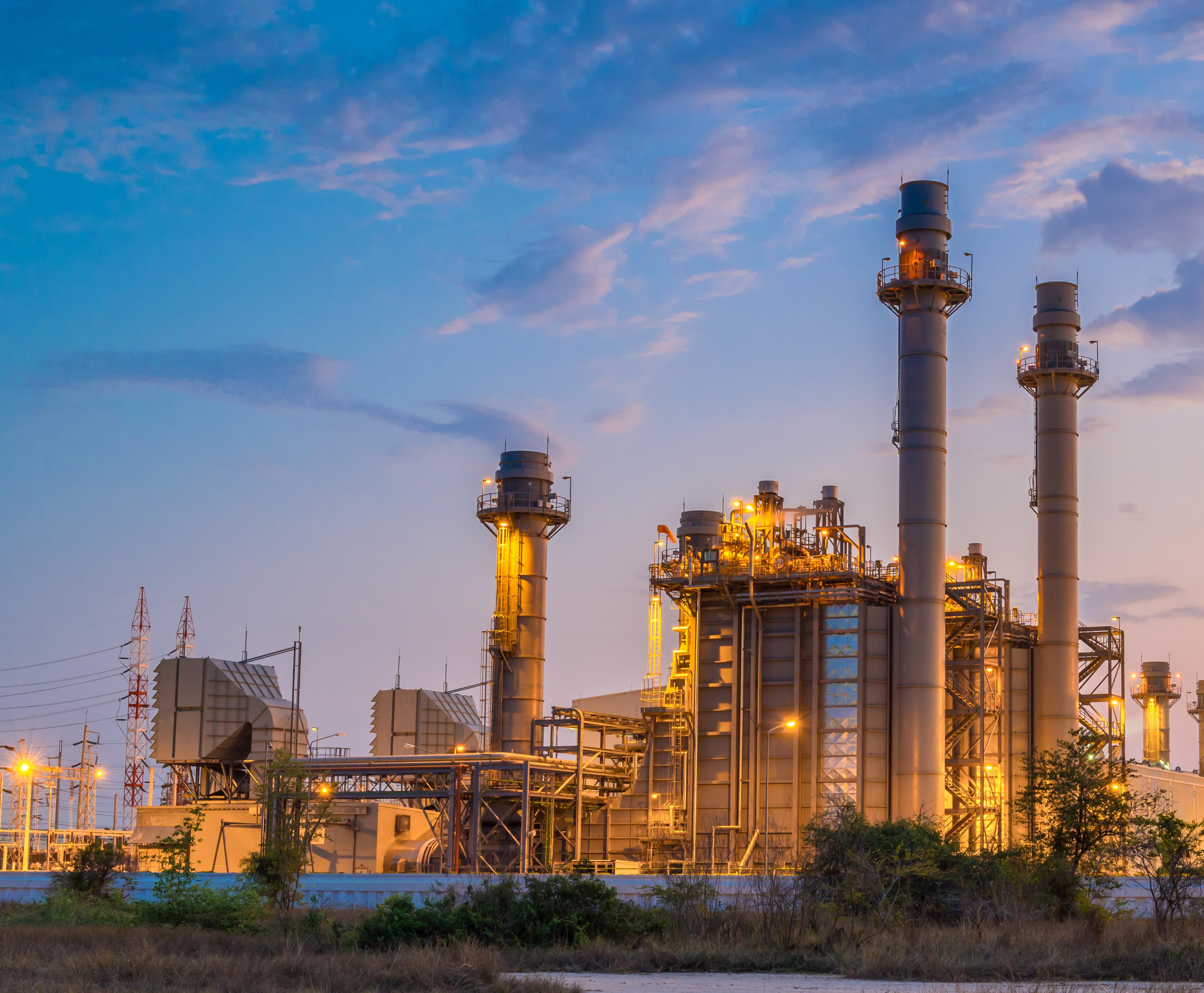
Thermal Power Generation: Thermal power generation is the most common method of generating electricity. It involves the burning of fossil fuels such as coal, oil, or gas to produce steam, which powers turbines that generate electricity. The fuel is burned in a furnace, and the resulting heat is used to boil water, creating steam that drives the turbines. While this method is relatively cheap, it is also the most polluting of all power generation methods.
Hydro Power Generation: Hydro power generation uses the energy of falling water to generate electricity. Dams are constructed across rivers, creating a reservoir of water. This water is then released through turbines, which generate electricity. Hydro power is a renewable and clean source of energy, but it requires specific geological and geographical conditions, such as a steady and reliable flow of water.
Wind Power Generation: Wind power generation involves the use of wind turbines to convert the kinetic energy of wind into electrical energy. The blades of the turbines are shaped like air foils and are attached to a rotor, which spins as the wind blows, turning a generator to produce electricity. Wind power is a renewable and clean source of energy, but it requires a steady and reliable supply of wind.
Solar Power Generation: Solar power generation uses photovoltaic cells to convert sunlight into electricity. These cells are made of semiconductor materials and produce electricity when exposed to light. Solar panels are typically installed on rooftops or in large fields to capture sunlight. Solar power is a renewable and clean source of energy, but it can be expensive to install and requires a lot of land area to produce significant amounts of electricity.
Nuclear Power Generation: Nuclear power generation involves the use of nuclear reactors to produce heat, which is then used to produce steam to power turbines that generate electricity. Nuclear reactors use the process of nuclear fission to produce heat. While nuclear power is a relatively clean source of energy, it produces highly radioactive waste that requires careful handling and storage.
Geothermal Power Generation: Geothermal power generation uses the heat of the earth’s core to produce steam, which is used to generate electricity. This involves drilling deep into the earth’s crust to access hot water and steam, which is then used to drive turbines. Geothermal power is a renewable and clean source of energy, but it requires specific geological conditions and can be expensive to set up.
Biomass Power Generation: Biomass power generation uses organic material such as wood, agricultural waste, and other plant material to produce heat, which is used to generate steam to power turbines that generate electricity. This method of power generation is considered renewable because organic material can be grown and harvested again, but it can also result in deforestation and is not as clean as other renewable sources of energy.
In summary, each type of power generation has its own set of advantages and disadvantages, and the choice of which type to use depends on factors such as cost, availability of resources, environmental impact, and geographical conditions.
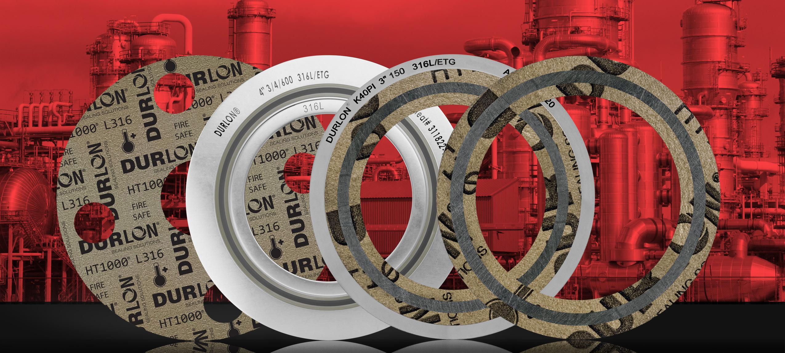
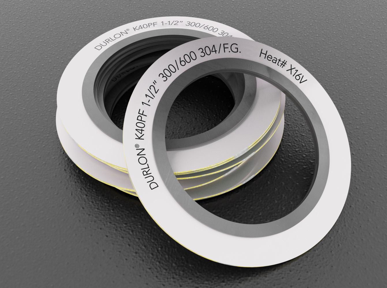
When exposing industrial bolted joints to extreme temperatures and pressure, you need to have the right gasket that not only provides effective sealing but lasts longer.
Gasket temperature limits can be classified into (but are not limited to) the following temperature ranges: Phyllosilicate 1000ºC (1832ºF), Flexible Graphite 450ºC (850ºF), Compressed Fiber 400ºC (750ºF).
When considering high temperature applications such as gas turbines, heat exchangers, exhaust manifolds and others commonly found in the refinery, power generation and chemical industries, Phyllosilicate is a good choice for the following reasons:
• high tensile strength
• low weight loss at extreme conditions
• chemically resistant
• laboratory tested for fire safety
• non-combustible
• sustainable solution
Phlogopite mica is a temperature resistant member of the phyllosilicates family. The combined content of phlogopite mica paper when impregnated with an inorganic binder at less than half the amount
found in vermiculite filled products, allows for superior weight retention; less than 5% weight loss at 800°C (1,472°F) and results in ultimate extreme temperature sealing performance up to 1,000°C (1,832°F).
Durlon® provides extreme temperature gaskets for industrial applications that require superior sealing performance, can effectively retain their stability at high temperatures, provide lower torque retention leakage rates, and reduce maintenance time.
Industrial sealing requires superior performing gaskets that can effectively retain their stability at high temperatures.
Some applications involve both high pressure and high temperature, and the right gasket for their use should match these needs with minimal chances of failure.
Over the years, Durlon® High Temperature gaskets have been known to offer the required resilience as may be required on industrial-scale applications.
To get the right gasket for your high temperature application, you need to be sure of its reliability and its ability to yield optimal results. Rely on Durlon® for high performance gaskets to match your needs.
(-40°F)
(900°F)
(650°F)
(-40°F)
(700°F)
(548°F)
/ Durtec® / Kammprofile
(-350°F)
(520°F)
(500°F)
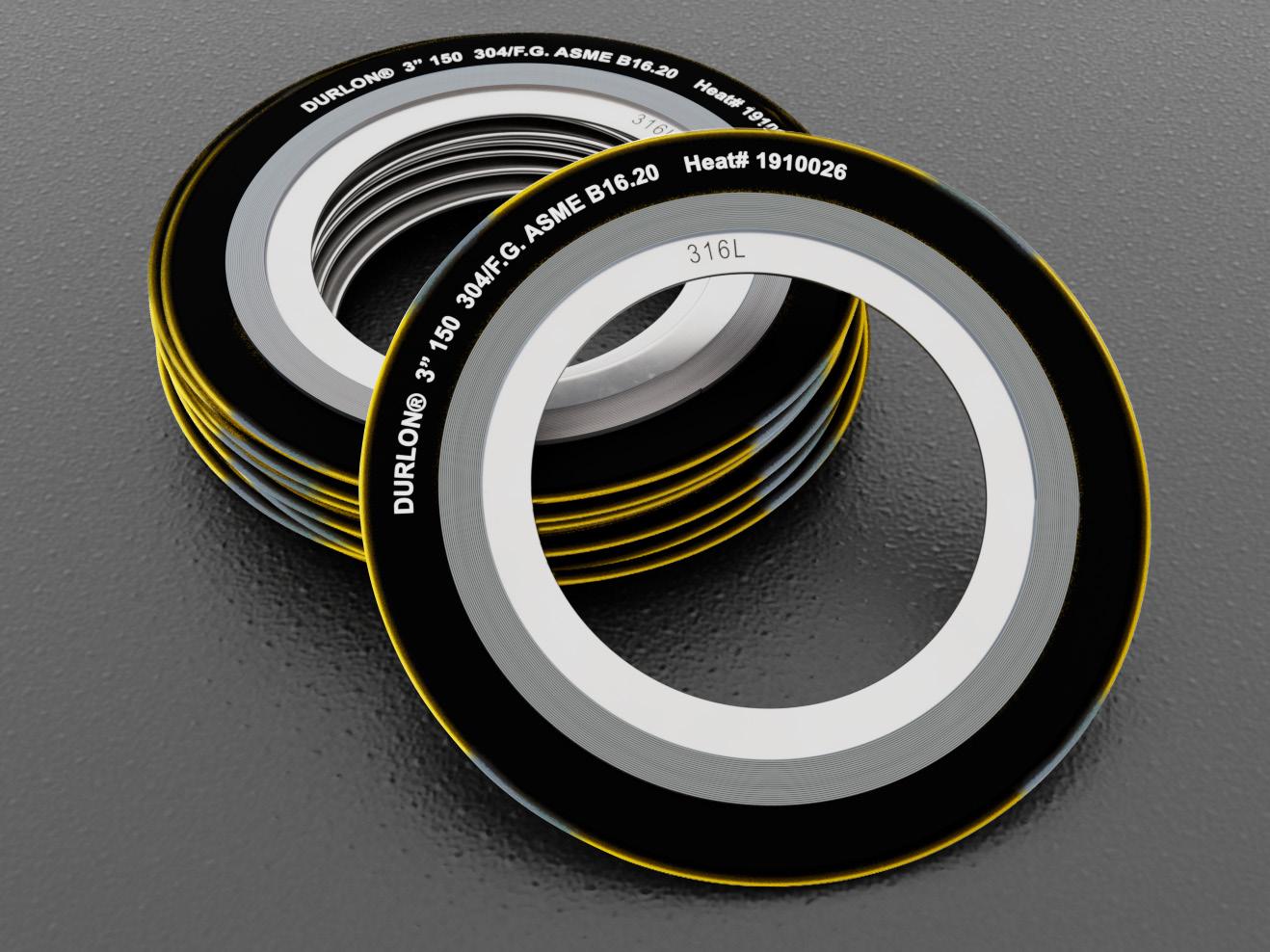
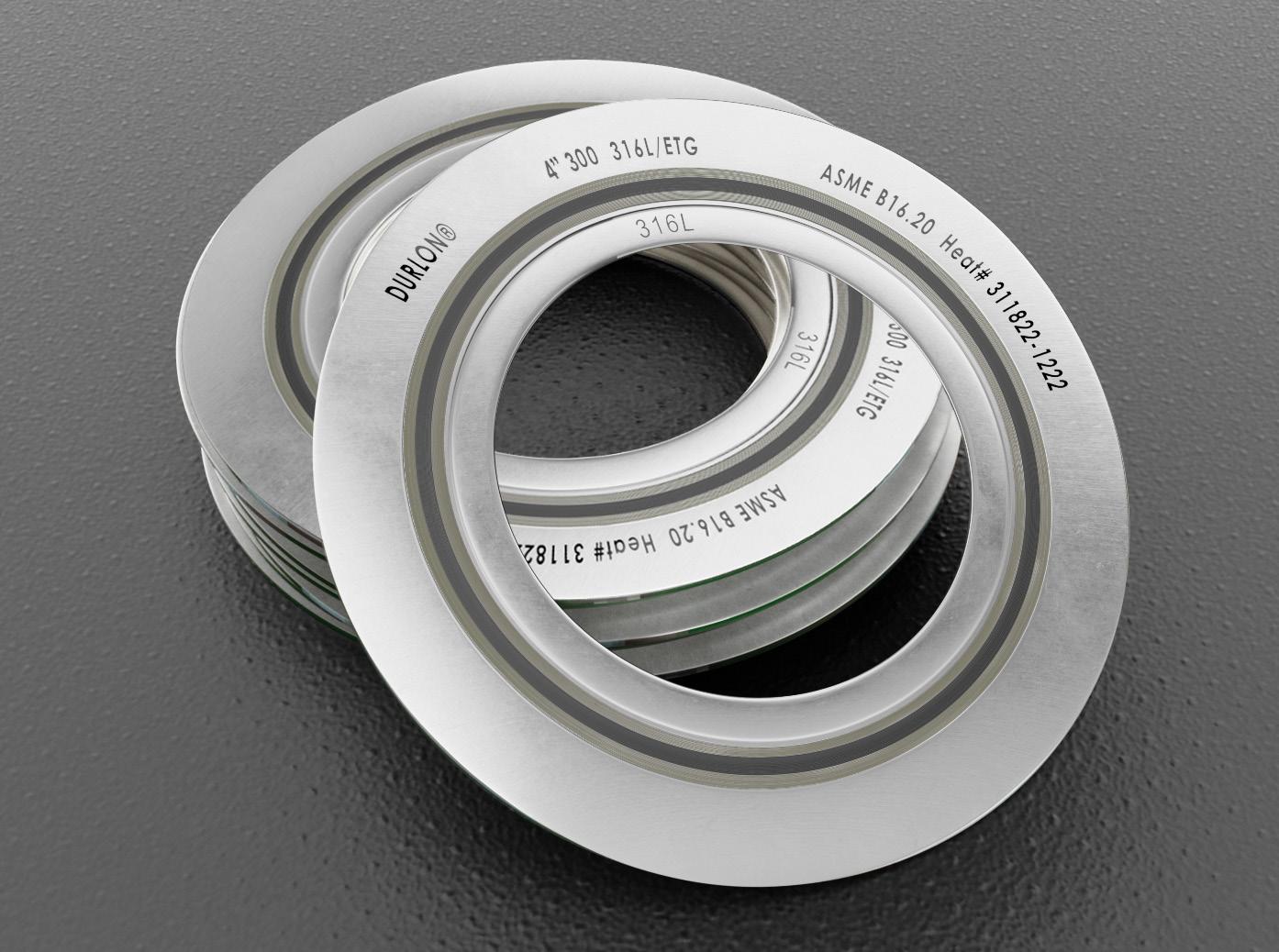
Durlon® SWG - All Durlon® SWG’s are manufactured according to ASME B16.20 standards. Quality Assurance complies with API Specifications Q1 and ISO 9001 standards. Super Inhibited Graphite meets the requirements of Shell Specification MESC SPE 85/203 and meets PVRC SCR Flexible Graphite Spec for FG 600 material. Durlon® ETG adds an inner and outer protection boundary in the form of a mica-phyllosilicate based sealing material - Durlon® HT1000® consists of phlogopite mica paper impregnated with an inorganic binder at less than half the binder amount found in a typical vermiculite-phyllosilicate filled product. This lower binder content allows for superior weight retention and results in ultimate extreme temperature sealing performance. Durlon® Kammprofile* - Max temperature is dependent on material used.
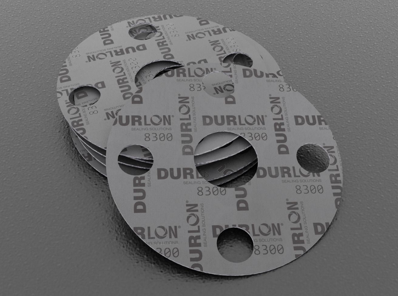
8300 Passed API 6FB, 4th Edition Fire Test, California Proposition 65, RoHS Reach Declaration.
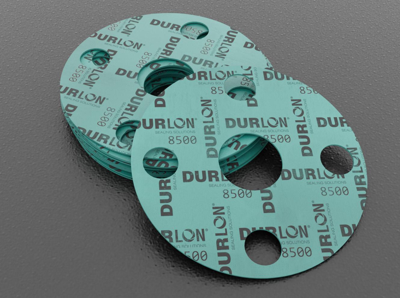
8500 California Proposition 65 and RoHS Reach Declaration compliant, API 6FB Fire Test with avg. temperature >650°C, 30 minutes, 40 bar, 1 ml (inch/min.) max allowable leakage, Conforms to the FDA requirements of 21 CFR 177.2600, ABS Tier2 - PDA Issued.
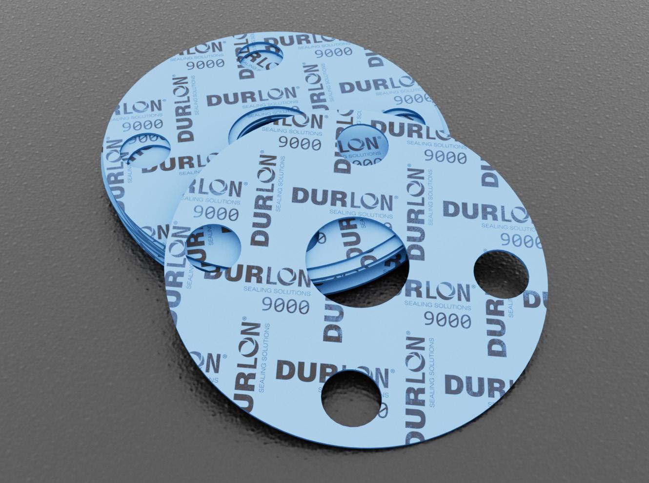
9000
Passed API 6FA, 3rd Edition Fire Test, Met requirements of 121ºC (250ºF) for USP for Plastic Class VI, Conforms to required 21 CFR 177.1550 for FDA, TA-luft (VDI Guideline 2440) approved material, ABS-PDA & Pamphlet 95 approved material - chlorine institute, (EC) 1935/2004 & EU (10/2011) approved material.
SWG TA-luft (VDI Guideline 2440), API Standard 6FB Fire Test- 6 inch Class 300 SWG FG
ETG API 6FB, Fourth Edition 2019,Type 1 (Onshore Test), API 6FB, Fourth Edition 2019,Type 2 (Offshore Test), API 607, 4th edition Fire Test with Exxon modifications.
Kammprofile RoHS Reach Declaration compliant. Physical Properties
Note: ASTM properties are based on 1/16” sheet thickness, except ASTM F38 which is based on 1/32” sheet thickness. This is a general guide only and should not be the sole means of accepting or rejecting this material. The data listed here falls within the normal range of product properties, but should not be used to establish specifications limits nor used alone as the basis of design. For applications above Class 300, contact our technical department.
Warning: Durlon® gasket materials should never be recommended when both temperature and pressure are at the maximum listed. Properties and applications stated are typical. No applications should be undertaken by anyone without independent study and evaluation for suitability. Never use more than one gasket in one flange joint and never reuse a gasket. Improper use or gasket selection could cause property damage and/or serious injury. Data reported is a compilation of field testing, field service reports and/or in-house testing. While the utmost care has gone into publishing the information contained herein, we assume no responsibility for errors. Specifications and information contained within are subject to change without notice. This edition cancels and obsoletes all previous editions.
TRANSMISSION LINES
SOURCE 2 3 4 5 6 7 8
PUMPING STATION
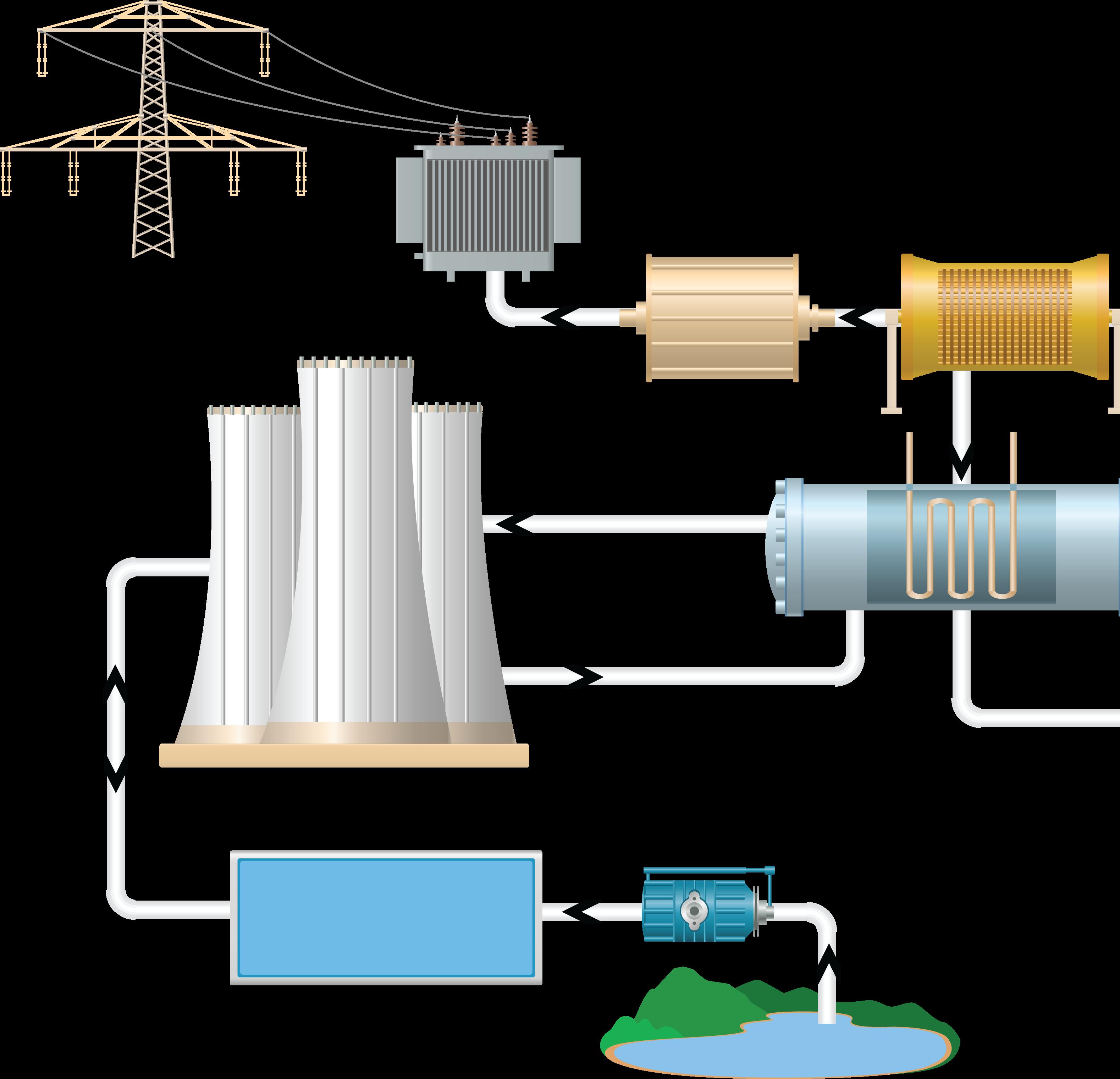
NOTE: This is a graphical representation of a thermal power plant process, showing the primary process flow path. It does not show the minor details of the process, rather it focuses on the equipment used, and other instruments that are present. It helps to illustrate how the major components of this type of process plant interacts with each other to bring about the desired effect.
SWG, ETG, Kammprofile
SWG, ETG, Kammprofile
SWG, ETG, Kammprofile
8300, 8500, 9000
8300, 8500, 9000
8300, SWG, ETG, Kammprofile
8500, 9000, SWG
8300, 8500, 9000, SWG
The following are the various stages involved in the flow process of a thermal power plant:
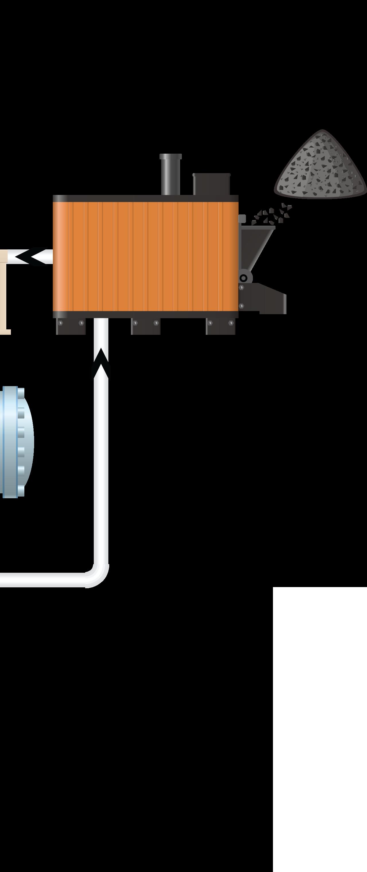
1. BOILER
The boiler is a large cylindrical vessel that is used to convert water into steam. The coal is burned in the boiler, and the heat generated by the combustion process is used to heat up the water, which turns into steam. The steam produced in the boiler is at very high pressure and temperature.
2. TURBINE
The steam from the boiler is directed to a turbine, which is a rotary engine that converts the thermal energy of the steam into mechanical energy. The steam enters the turbine at a high velocity, causing the turbine blades to spin rapidly.
3. GENERATOR
The spinning turbine is connected to a generator, which is a device that converts the mechanical energy of the turbine into electrical energy. The generator consists of a large coil of wire that is rotated within a magnetic field, generating an electric current.
4. TRANSFORMER
The electrical energy generated by the generator is in the form of high voltage, low current AC (alternating current). The voltage is increased using a transformer, which is a device that uses electromagnetic induction to change the voltage of the electricity.
5. TRANSMISSION
The high-voltage electricity is then sent through transmission lines to a substation, where the voltage is lowered to a level that can be used by homes and businesses.
6. CONDENSER
The steam that has passed through the turbine is cooled and condensed back into water in the condenser. The cooling is achieved by passing the steam over a series of tubes that are cooled by cold water from a nearby source, such as a river or lake.
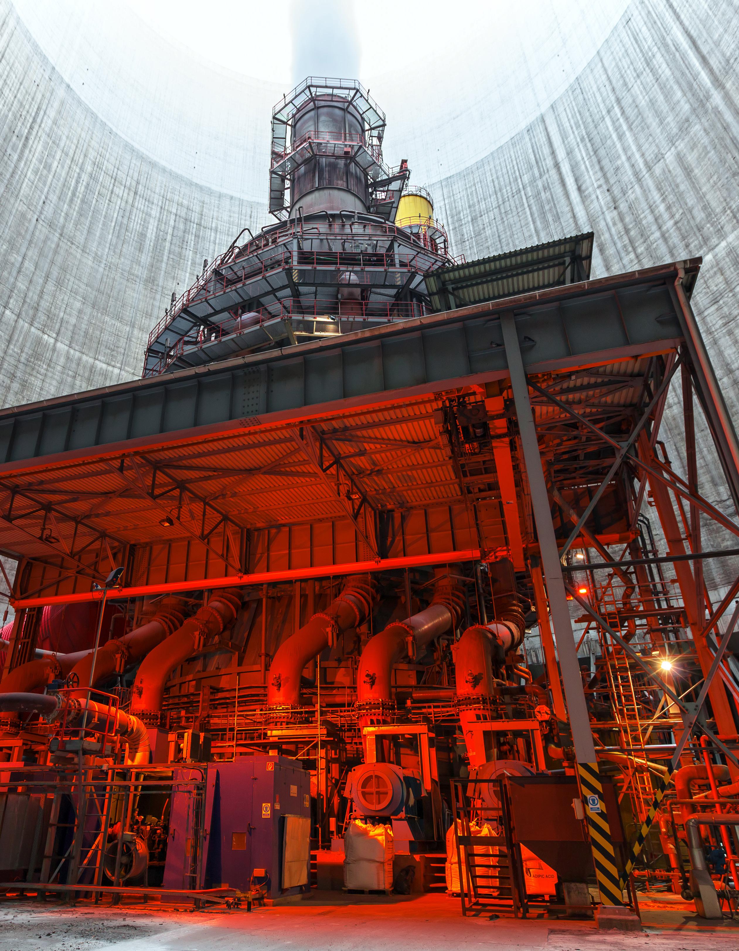
7. COOLING TOWER
The hot water from the condenser is pumped to a cooling tower, which is a large structure designed to cool the water by evaporation. The hot water is sprayed into the tower, where it comes into contact with a flow of cool air, causing the water to evaporate and dissipate its heat.
8. RETURN WATER
The cooled water is then returned to the condenser to be used again in the thermal power production process.
The core of the Durlon® brand is to provide fluid sealing solutions that make sense, both financially and strategically. We accomplish this through process-oriented design, sector-specific knowledge, and extensive testing. Our goal is to ensure
performance and safety while adhering to the quality management system registered to ISO 9001:2015.
At Durlon®, we offer specially developed sealing solutions tailored directly to your specific needs.
Distributed by: