Gasket Manual

Welcome
Thank you for choosing the Durlon® Gasket Manual, your comprehensive guide to gasket selection, installation, and performance. Whether you’re an engineer, maintenance professional, or industry specialist, this manual is designed to provide valuable insights into gasket materials, technical data, installation best practices, torque values, chemical resistance charts, and more. It serves as a go-to resource for optimizing sealing solutions in a wide range of applications.
Inside, you'll find in-depth knowledge of gasket fundamentals, material properties, and custom capabilities, ensuring you have the right tools to make informed decisions for your sealing needs. Our goal is to equip you with the expertise to enhance system reliability, safety, and efficiency. We hope this manual becomes an indispensable part of your operations, and we appreciate the opportunity to support your success with Durlon® Sealing Solutions.
At Durlon®, we are committed to continuous innovation and quality, ensuring our gasket solutions meet the highest industry standards. This manual not only provides essential guidelines but also offers troubleshooting tips and real-world application examples to help you overcome common sealing challenges. Whether dealing with extreme temperatures, aggressive chemicals, or high-pressure environments, our comprehensive resources will guide you in selecting the most suitable gasket for your specific needs. By leveraging the expertise within these pages, you can maximize the longevity and performance of your sealing solutions, ultimately improving operational efficiency and reducing downtime.
Durlon® 5000
Durlon® 7900/7925/7950
Durlon® 7910
Durlon® 8300
Durlon® 8400
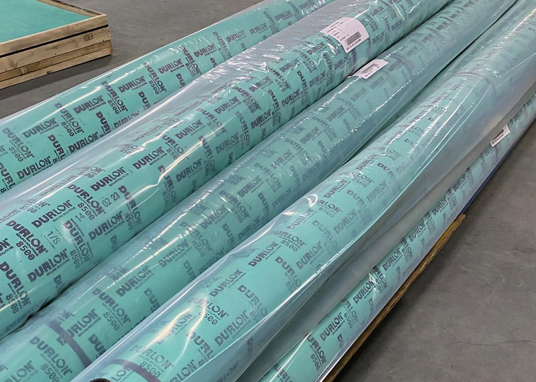
Durlon® 8500
Durlon® 8600
Durlon® 8700 Durlon® 8900
Durlon® HT1000®
Durlon® 9002
Durlon® 9200
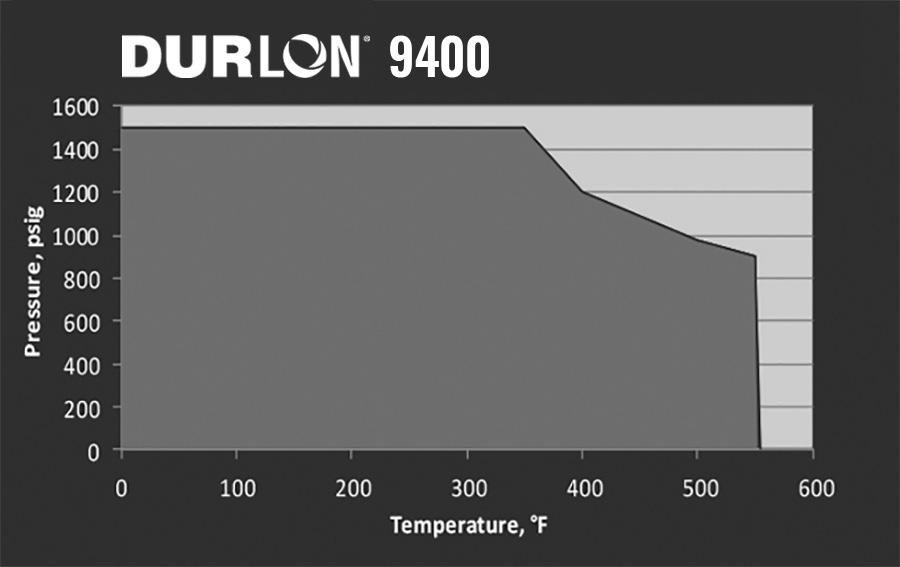
Durlon® 9400
Durlon® 9600
Durlon® 9645 -
Durlon®
Durlon®
Gasket Installation
Gasket Factors

Gasket Dimensions
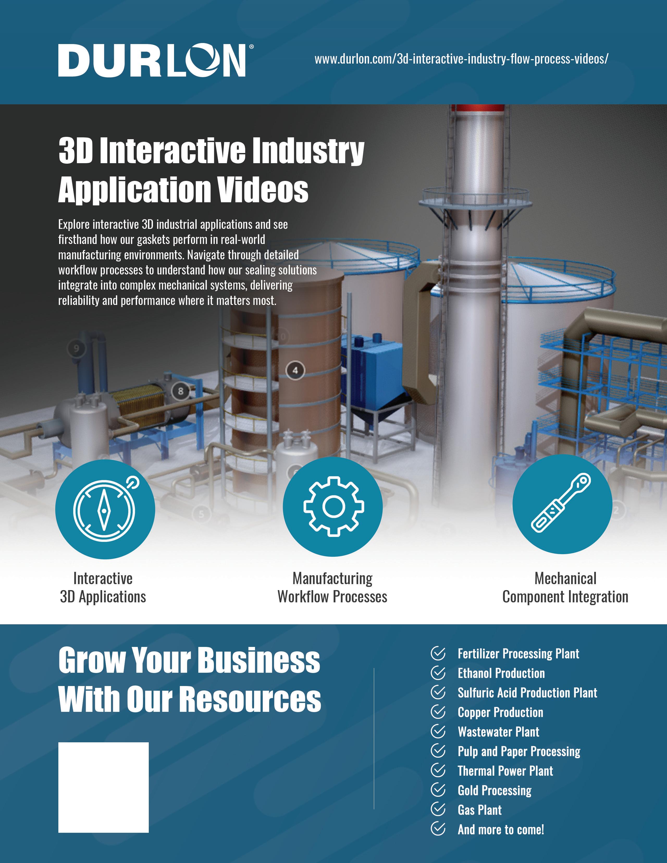
3D
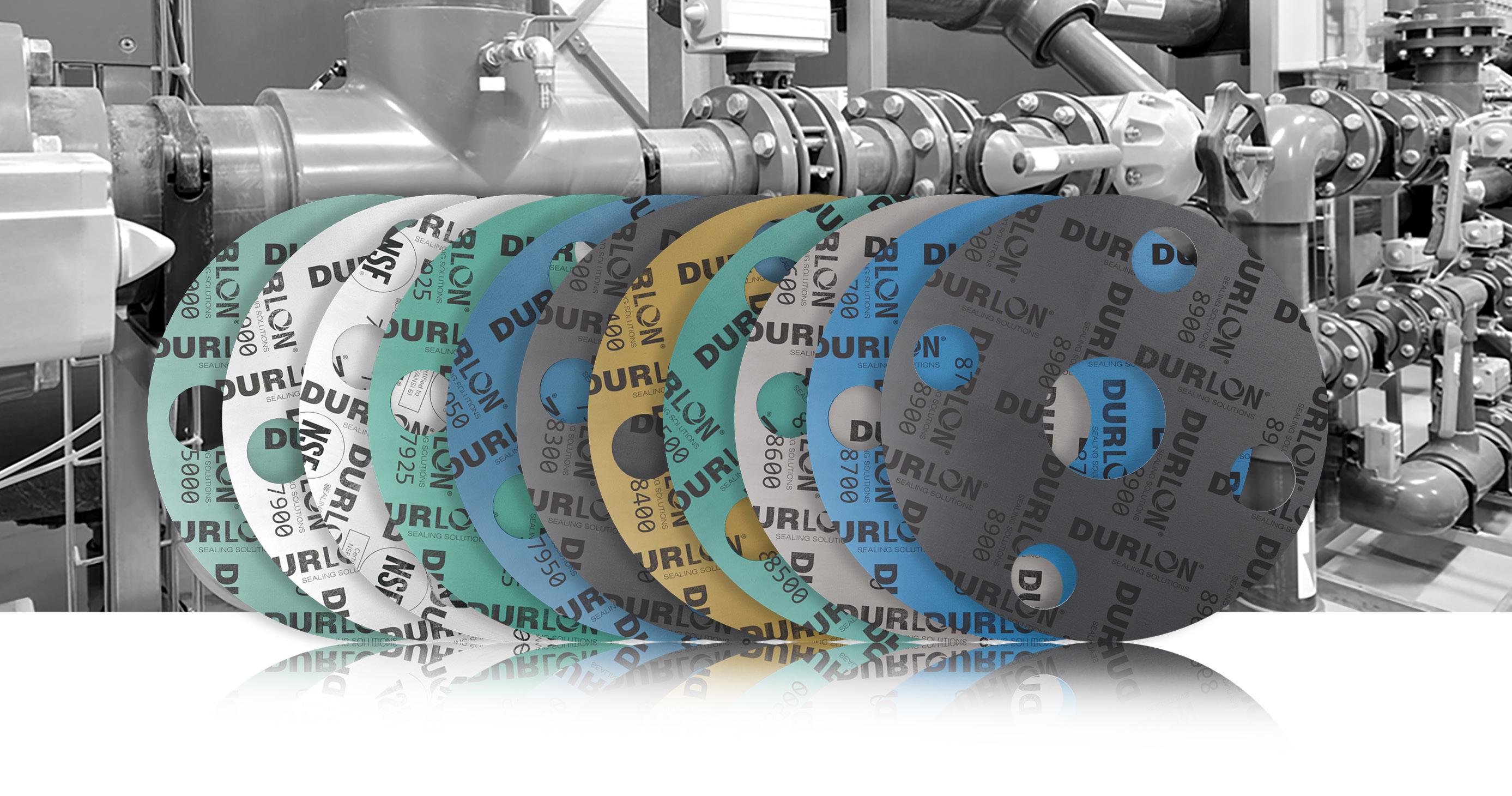
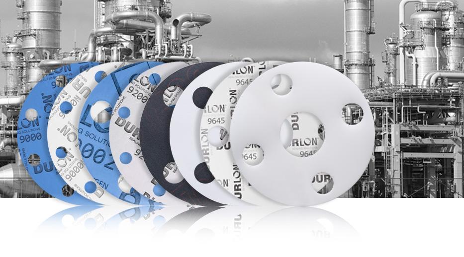
Our Sealing Products
Durlon® Sealing Products have the widest possible range of service applications in comparison to major competitors, therefore, the number of different types of gaskets required to be inventoried can be greatly reduced. This impacts process safety, because limiting the number of gasket styles reduces the chance of installing the wrong gasket in the wrong service. For these reasons, more and more original equipment manufacturers and industrial consumers are specifying Durlon® gasket materials for their needs.
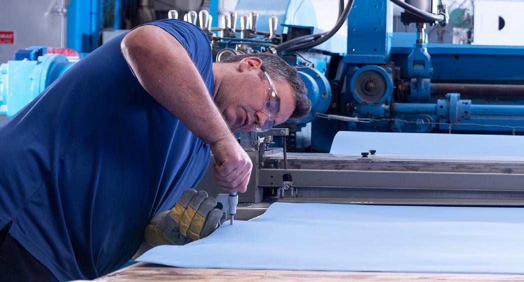
Durlon® compressed non-asbestos gasket materials are high-density products featuring the most homogeneous combination of minerals, synthetic fibers, and elastomers. They are used in a wide variety of industries on a broad range of chemical applications at varying temperatures and pressures. Their excellent flexibility prevents large, narrow flange gaskets from breaking during cutting and installation, and their superior recovery ensures tight sealing during thermal cycling.
Durlon® filled PTFE and flexible graphite gasket materials compliment our compressed sheet family, by giving you the right gasket for all of your gasket needs.
Durlon® PTFE gaskets are exclusively manufactured at our factory located in Belleville, Ontario, Canada. Our compression molded and skived manufacturing process allows for the best control of physical properties and performance characteristics as compared with other manufacturing processes. With unique formulas of fillers, Durlon® PTFE products can meet your tough chemical applications and engineering specifications.
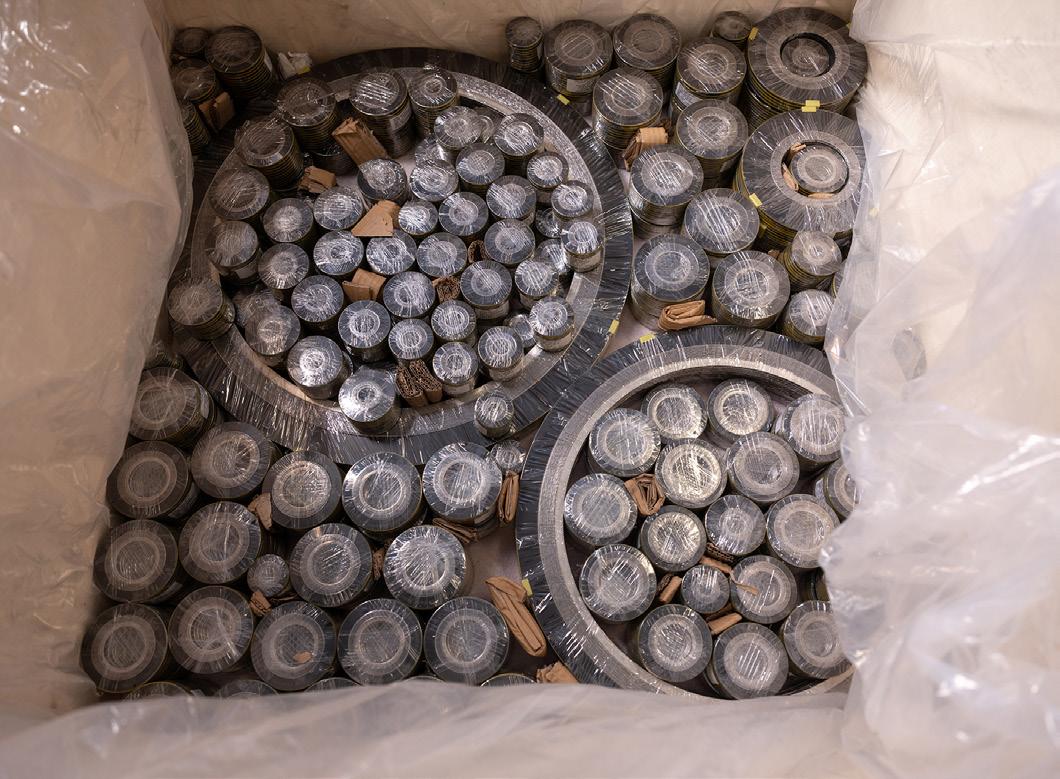
Durlon® metallic gaskets are manufactured from a combination of metals and designed to withstand extreme temperatures, pressures
and chemical exposure. Available in standard and custom configurations, these rugged metal gaskets are made of a wide range of materials to accommodate all types of process applications.
Durlon® semi-metallic gaskets include both metallic and non-metallic components, either containing a metal core with sealing materials on both flat surfaces, or a pliable core encased in a thin metallic casing. They are most popular due to this configuration, and are available in a wide variety of styles and sizes. They can typically be fabricated of any metal which is available in thin strip or sheet, and which can be welded. Therefore, they can be used against virtually any corrosive medium dependent upon the choice of the metal and filler/facing material.
Our computer-aided manufacturing process uses rigorous quality control programs to ensure premium quality product performance. The metallic component gives the gasket superior structural integrity, while the non-metallic element ensures the superior sealing.
OUR MISSION
To provide global industries with high quality sealing solutions that are innovative, cost effective, and reduce fugitive emissions. We strive to grow our business with a keen eye towards customer service and delivering value to our employees, and customers through training and development opportunities, and world class technical support. “If it needs to stay between the pipes, it needs to be Durlon®”
We will accomplish this by:
• Our commitment to understanding and meeting or exceeding our customer’s expectations and requirements
• Continual improvements of our products, services and processes
• Remembering that we are here because of our customers
ADDITIONAL FEATURES
• Reliability backed by many years of experience
• Local distribution for quick and easy delivery
• Branding for easy identification and assurance of genuine Durlon® gasket material helps prevent misapplication
• A release agent on both sides of the CNA sheet ensures good anti-stick properties
Durlon® products are used in virtually every industrialized corner of the world. Our gasket materials are manufactured to ISO 9001 quality standards and are subjected to continuous testing and rigid quality control, ensuring unvarying performance on the job.
Our state-of-the-art research and development facility is geared to meet the ever changing demands required in today’s variety of service conditions. Since their inception, Durlon® gasket materials have undergone many enhancements, each incorporating the latest technology to better meet the wide variety of industry’s changing needs.
We recognize that today more emphasis is being placed on fugitive emissions via the Clean Air Act in Canada and the United States, as well as various regulations in other countries. One of our prime design objectives is to maximize the sealability of our gasket materials to meet and exceed fugitive emission requirements.
Our Group of Companies
The Durlon® brand represents global leadership in sealing solutions with proven reliability, innovative processes and sustainable integrity in a wide range of demanding applications – oil & gas, chemical processing and power generation, to name just a few. We assure highquality, environmentally-friendly materials from CNA & PTFE gasket sheets to flexible, metallic and high temperature gaskets.

Durabla Canada Ltd.
293 University Avenue
Belleville, ON K8N 5S3 Canada 844 636 1100
sales@durabla.ca www.durabla.ca

Gasket Resources Inc. 1814 Highway 146 South Suite 500
La Porte, TX 77571 866 707 7300 sales@gasketresources.com www.gasketresources.com

Triangle Fluid Controls Ltd.
399 College St. E Belleville, ON K8N 5S7 Canada 866 537 1133
info@trianglefluid.com www.trianglefluid.com

Durabla Asia Pte Ltd. 2 Venture Drive #12-18 Vision Exchange Singapore 608526 (65) 9722 1438
gasketinfo@durablaasia.com.sg www.durablaasia.com.sg
Gasket Resources Inc.
280 Boot Road Downingtown, PA 19335 USA 866 707 7300
sales@gasketresources.com www.gasketresources.com

Durabla Fluid Controls (Nantong) Co., Ltd. 88 Linjiang Avenue, Linjiang Town Haimen District, Nantong City 226132 Jiangsu Province, P.R.China (86) 513 82222386/13816120534 infochina@durlon.com www.durlon.cn
Compressed Non-Asbestos (CNA)
What is Compressed Non-Asbestos (CNA) gasket material?
Compressed Non-Asbestos is a sealing material consisting of a blend of organic and inorganic chemically resistant fibers and fillers together with an elastomer binder. The type of binder used is a key factor to consider when choosing a Compressed Non-Asbestos sheet for gasketing applications.
Manufacturers of compressed non-asbestos sheet produce a variety of materials that differ in the type of fibers and binders used which are purpose-suited for specific applications. Some sheets are designed for general service applications, while others are designed for use in applications involving chemicals, oils, extreme temperatures, etc.
How does Compressed Non-Asbestos differ from elastomers?
An elastomer is a polymer which possesses an elastic property. Elastomers are generally thermo-set materials which require curing through heat and pressure with the addition of sulfur or other curing agents. Natural and synthetic rubbers, such as styrene-butadiene rubber (SBR) and Buna-N (NBR), are elastomers.
Compressed Non-Asbestos, in contrast, is a material that combines organic and inorganic chemically resistant fibers and fillers. This type of binder employed gives the sheet the properties of elasticity and flexibility, while the fibers used give the sheet specific sealing characteristics and properties.
Why use Compressed Non-Asbestos sheets?
Compressed Non-Asbestos sheets have been developed to service a wide variety of sealing applications. These materials are an excellent choice for both general and severe service sealing applications.
Because Compressed Non-Asbestos sheets employ various combinations of fibers and binders, sheet manufacturers are able to produce a range of sheets with different mechanical specifications. Gaskets made from Compressed Non-Asbestos sheets have excellent sealing characteristics, torque retention, heat, and chemical resistance. These types of gaskets are an excellent choice for applications involving water, air, steam, oils, acids, and general chemicals. Our high performance industrial non-metallic gasket material sheetsCompressed Non-Asbestos contain high-pressure and high-temperature aramid fiber materials that are perfect for sealing, thermal, and mechanical applications (petrochemical, chemical, steam, pulp & paper, pharmaceutical and potable water industries).
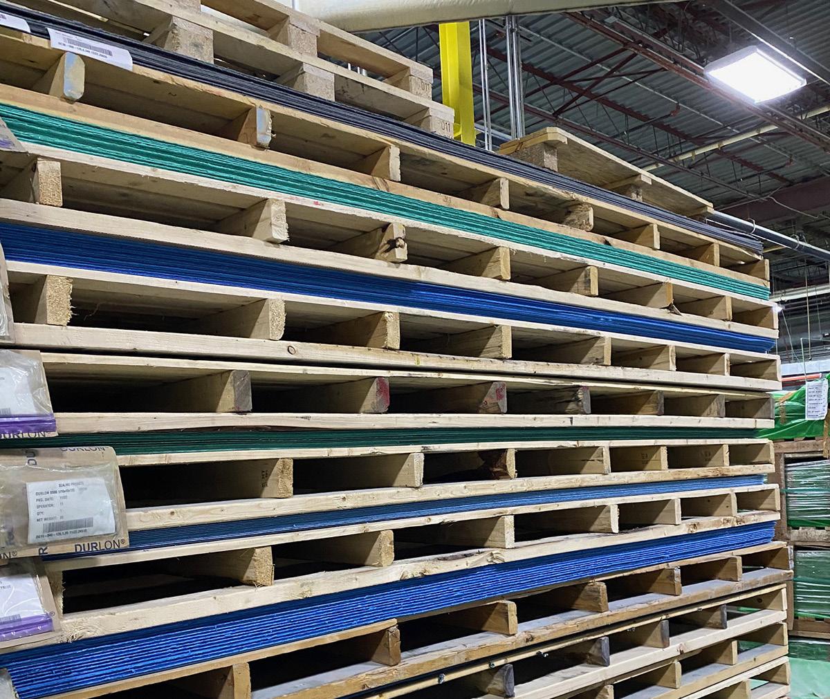
Durlon® Compressed Non-Asbestos products range from economical to premium grades with organic and inorganic chemically resistant fibers and fillers to meet the majority of general service industrial piping applications and are the only products in its class to be manufactured by Durabla® Canada Ltd., and have been since the early 1980s. Explore our CNA product styles for the one that meets your application requirements.
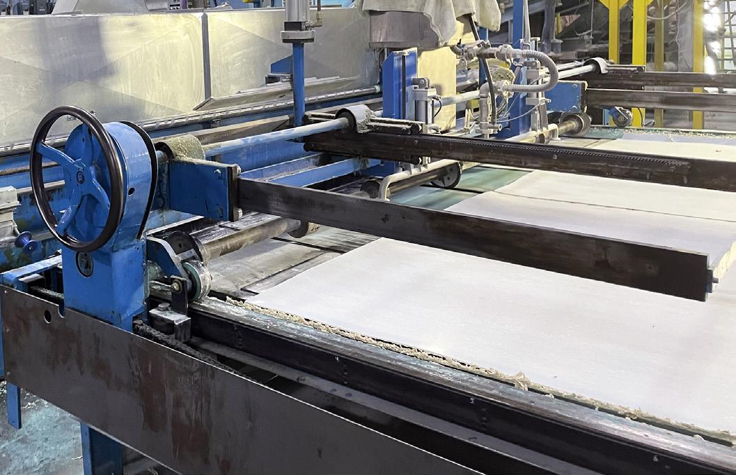
Durabla® Canada Ltd. is a world leading manufacturer of Compressed Non-Asbestos Gasket Sheeting (CNA) for sealing, thermal, and mechanical applications. These high-pressure and high-temperature fiber gasket sheet materials are supplied to petrochemical, chemical, steam, pulp & paper, pharmaceutical and potable water industries.

Durabla® Canada Ltd. adheres to rigid testing and quality control practices; all industrial products conform to ISO 9001:2015 Standards. The on-site research and development facilities is where technicians and the chief chemist produces and
tests custom sealing products to ensure high performance gasket material sheets for various industry applications.

Quality Assurance is a critical component of Durabla® Canada Ltd. The state-of-the-art facility, on-site research and development lab and products meet or exceed customer expectations. All Durabla® Canada Ltd. manufactured products undergo rigorous testing methods (ASTM) including leakage detection, and equipment is calibrated and traceable to NIST (National Institute of Standards and Technology). Products manufactured have full traceability from the raw materials all the way through each stage of the manufacturing process until it leaves the facility.

ENHANCED ANTI-STICK FORMULATION
Many gasket users have encountered problems with various compositions associated with flange adhesion for years.
Apart from the separation of flanges, surface imperfections can result from careless gasket removal. At elevated temperatures and pressures, there is a tendency for gasket materials to become embedded in the flange on opening. Sometimes disintegrated pieces stick to both flange mating surfaces, resulting in difficulty when removing the adhering gasket material in a safe, timely manner and without damaging the flanges.
To overcome this problem, anti-stick technology is incorporated into the manufacturing process of the Compressed Non-Asbestos Durlon® products. This technology allows for improved separation from flange surfaces during removal, saving time and energy.
This new technology allows Durlon® CNA to be the best in the industry; gasket and sheet materials have passed the MIL-G-24696
Navy Adhesion Test: 48 hrs at 366°F (186ºC).

MILITARY ADHESION MIL-G-24696
Adhesion Comparison between gaskets produced with Anti-Stick and without Anti-Stick.
Sample size: 1.25” X 2.0” X ¹⁄16 ”
Installation: Between two platens - Carbon Steel and Stainless Steel Torque: 30 ft-lb.
Test Conditions: 48 hours at 366ºF (186ºC)

WITH Anti-Stick Technology
Gasket can be removed in one piece. Only a small amount of the face material remains on the surface of the flange.
Mil-G-24696 Rate: 1-2

Many times, wire brushing or wire wheels are common practices, but if not done properly can lead to damaged process equipment or system contamination.
Mil-G-24696 Rating (A lower value is favorable):
1 - Gasket can be removed cleanly with virtually no remaining residual material.
2 - Only a small amount of face material remains when gasket is removed.
3 - Can be removed in one piece but some face material remains on platen.
4 - Can be removed in one piece but a considerable amount of face material remains.
5 - Cannot be removed in one piece and delaminates upon removal.
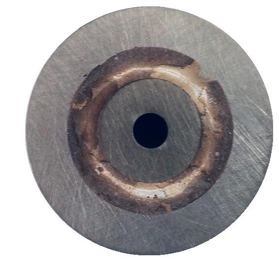
WITHOUT Anti-Stick Technology
Gasket cannot be removed in one piece. Part of the face material remains on the surface of the flange.
Mil-G-24696 Rate: 4-5
A good quality commercial grade compressed non-asbestos sheet with good chemical resistance for moderate service conditions suitable for oil, water, mild alkalis, mild acids, hydrocarbons and solvents.
INDUSTRY APPLICATIONS:
• Chemical Processing
• Food & Beverage
• General Industry
• Marine
Mineral Fiber with NBR Rubber Binder
Compressed Non-Asbestos Gasket Material
ASTM F104: F712120-A9B4E12K5L051M5
• Oil & Gas • Water & Wastewater Physical Properties
Mining
OEM Services
Increase, %
Increase, %
Fuel B 5hrs at 70°F
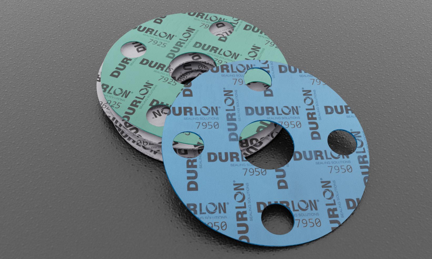
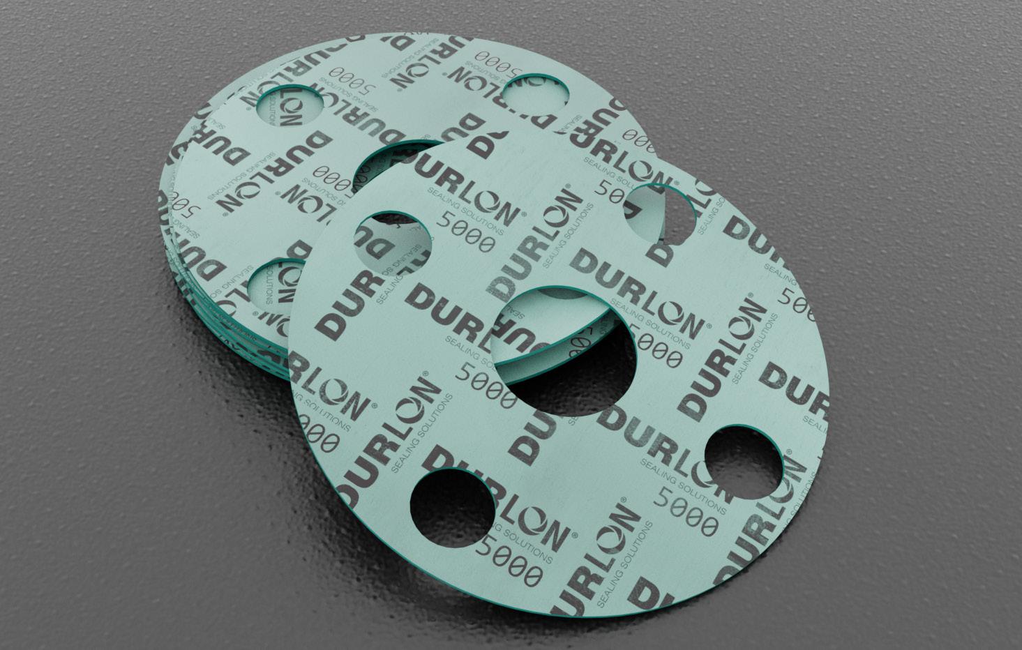
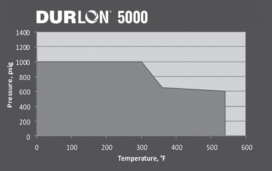
Durlon® 7900/7925/7950 are an economy grade general service gasket sheet material made with NBR (Nitrile Butadiene Rubber) binder for mild service in piping and equipment with applications in steam, hydrocarbons and refrigerants and an alternative when temperature and pressure conditions are below 500ºF (260ºC) and 1,200 psig (See PxT chart below for validation).
INDUSTRY APPLICATIONS:
Certifications
California Proposition 65 Compliant
RoHS Reach Declaration Compliant

7900/7925/7950
Aramid with NBR Rubber Binder
Compressed Non-Asbestos Gasket Material ASTM F104: F712120-A9B3E22K5L151M5
Physical Properties
Color 7900/7925/7950 Off White/Green/Blue
Fiber System Aramid/Inorganic
Binder NBR Temperature: Min Max
(psi)
(1,200)
g/cc (lbs/ft3) 1.7 (106)
% 7-17
%
Relaxation, %
Strength, MPa (psi)
Nitrogen Sealability
2378, cc/min
Fluid Resistance, ASTM F146 IRM 903 Oil 5hrs at 300°F
Increase, %
Increase, %
Fuel B 5hrs at 70°F
ASTM F147
(1,600)
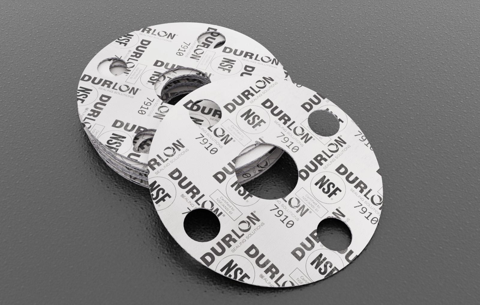
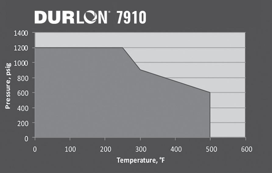
As a quality, commercial grade compressed sheet gasket material, Durlon® 7910 was specifically developed to meet the requirement of NSF/ANSI 61 (Certification for water treatment products that are manufactured, distributed or sold in North America) for potable water application 23°C (73°F) to commercial hot 82°C (180°F).
INDUSTRY APPLICATIONS:
• General Industry
BENEFIT:
• OEM Services
• Water & Wastewater
Durlon® 7910 has a strong dielectric rating, making it ideal for isolation kit applications where compressed fiber sheet gaskets can be utilized.
Durlon® 7910 is manufactured by Durabla® Canada Ltd.
Certifications
NSF/ANSI 61 Certified to meet requirement of NSF/ANSI 61 for potable water application at 23ºC (73ºF) to commercial hot to 82ºC (180ºF)
RoHS Reach Declaration Compliant
NSF Certified: NSF International is a global independent organization that writes standards and protocols, and tests and certifies products for the food, water and consumer goods industries to minimize adverse health effects and protect the environment. www.nsf.org
Aramid with NBR Rubber Binder
Compressed Non-Asbestos Gasket Material
ASTM F104: F712120-A9B3E22K5L151M5
Physical Properties
Color White
Fiber System
Aramid/Inorganic
Binder NBR
Temperature: Min Max Continuous, Max
(-40°F)
(700°F)
(500°F)
Pressure, Max, bar (psi) 83 (1,200)
Density, g/cc (lbs/ft3) 1.7 (106)
Compressibility, % 9-19
Recovery, % 40
Creep Relaxation, % 25
Tensile Strength, MPa (psi) 11 (1,600)
Nitrogen Sealability
ASTM 2378, cc/min 0.05
Fluid Resistance, ASTM F146
IRM 903 Oil 5hrs at 300°F
Thickness Increase, %
Weight Increase, %
ASTM Fuel B 5hrs at 70°F
Thickness Increase, %
Weight Increase, % 0-15
ASTM F147
Note: ASTM properties are based on 1/16” sheet thickness, except ASTM F38 which is based on 1/32” sheet thickness. This is a general guide only and should not be the sole means of accepting or rejecting this material. The data listed here falls within the normal range of product properties, but should not be used to establish specifications limits nor used alone as the basis of design. For applications above Class 300, contact our technical department.
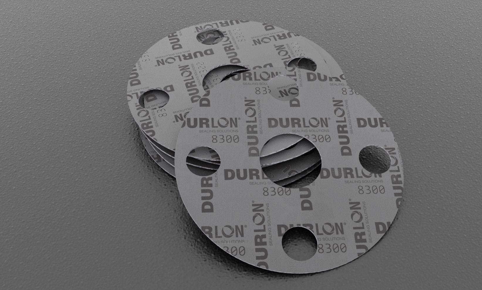
Durlon® 8300 is a premium grade compressed sheet gasket material that is excellent in steam and hydrocarbon services for the refining, petrochemical, and power generation industries. This gasket material is designed to handle the extreme pressure and temperature applications that include oil, water, mild alkalis, mild acids and solvents.
INDUSTRY APPLICATIONS:
• Chemical Processing
• General/Heavy Industry
• Mining
• OEM Services
Oil & Gas
Petrochemical
Power Generation
Refining
Certifications
API 6FB, 4th Edition Fire Test Passed
California Proposition 65
RoHS Reach Declaration
Compliant
Compliant
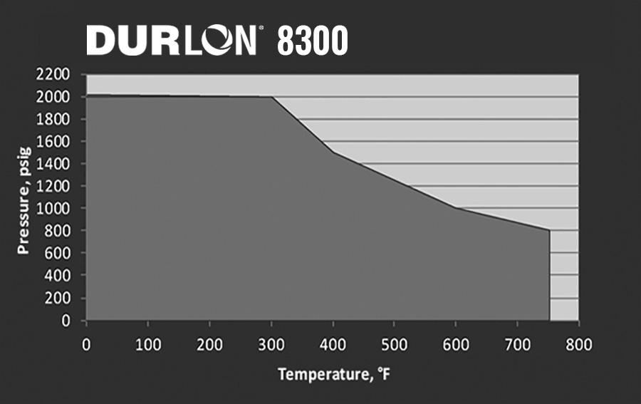
Note: ASTM properties are based on 1/16” sheet thickness, except ASTM F38 which is based on 1/32” sheet thickness. This is a general guide only and should not be the sole means of accepting or rejecting this material. The data listed here falls within the normal range of product properties, but should not be used to establish specifications limits nor used alone as the basis of design. For applications above Class 300, contact our technical department.
Carbon Fiber with NBR Rubber Binder
Compressed Non-Asbestos Gasket Material
ASTM F104: F712120-A9B3E22K5L311M5
Physical Properties
Color
Max, bar (psi)
g/cc (lbs/ft3)
(100)
(1,800) Nitrogen Sealability ASTM 2378, cc/min
Fluid Resistance, ASTM F146
IRM 903 Oil 5hrs at 300°F
Thickness Increase, %
Weight Increase, %
ASTM Fuel B 5hrs at 70°F
Increase, %
Increase, %
ASTM F147
Breakdown
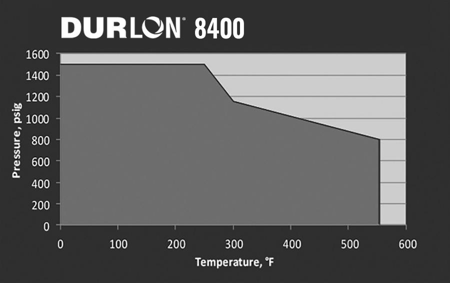
With an extremely wide pH application range (2-13 at room temp.)
Durlon® 8400 can be used in process piping and equipment in chemical, pulp & paper and other general industrial applications. A unique highperformance compressed sheet, Durlon® 8400 is an excellent gasket material for use in steam, mild caustics and acids.
INDUSTRY APPLICATIONS:
• Chemical Processing
• Food & Beverage
• General/Heavy Industry
• Mining
BENEFIT:
• OEM Services
• Power Generation
• Pulp & Paper
• Water & Wastewater
Durlon® 8400 has a strong dielectric rating, making it ideal for isolation kit applications where compressed fiber sheet gaskets can be utilized.
Phenolic Fiber with NBR Rubber Binder
Compressed Non-Asbestos Gasket Material
ASTM F104: F712120-A9B4E22K5L911M5
Physical Properties
Color
Certifications
(554°F) Pressure, Max, bar (psi)
(1,500) Density, g/cc (lbs/ft3) 1.7 (106)
Compressibility, % 8-16 Recovery, %
Creep Relaxation, % 25 Tensile Strength, MPa (psi)
Nitrogen Sealability ASTM 2378, cc/min 0.03
Fluid Resistance, ASTM F146 IRM 903 Oil 5hrs at 300°F Thickness Increase, % Weight Increase, %
Fuel B 5hrs at 70°F
Increase, %
Increase, %
Breakdown

A high performance compressed gasket material for use in process industries including pulp & paper, food & beverage, pharmaceutical, hydrocarbon, chemical, refinery and general industry. Durlon® 8500 is suitable for oils, water, steam, new generation refrigerants, dilute acids and alkalis, and many other liquids and gases.
Aramid/Inorganic with NBR Rubber Binder Compressed Non-Asbestos Gasket Material ASTM F104: F712120-A9B3E12K5L151M6
Physical Properties
Fluid Resistance, ASTM F146 IRM 903 Oil 5hrs at 300°F
/ Weight Increase, %
Fuel B 5hrs at 70°F
/ Weight Increase, %

BENEFIT: Durlon® 8500 has a strong dielectric rating, making it ideal for
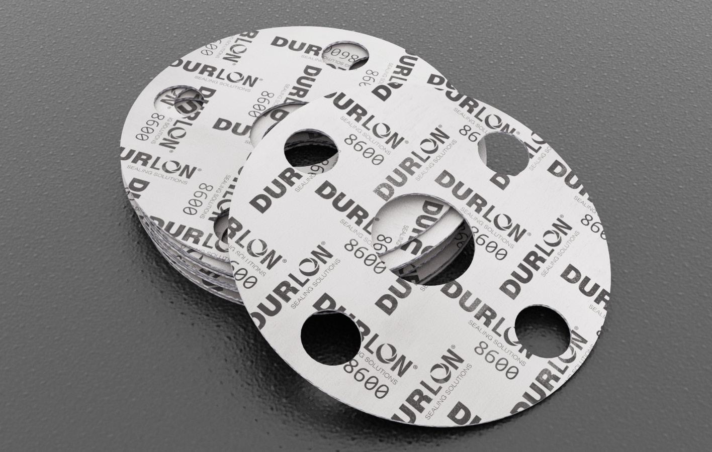
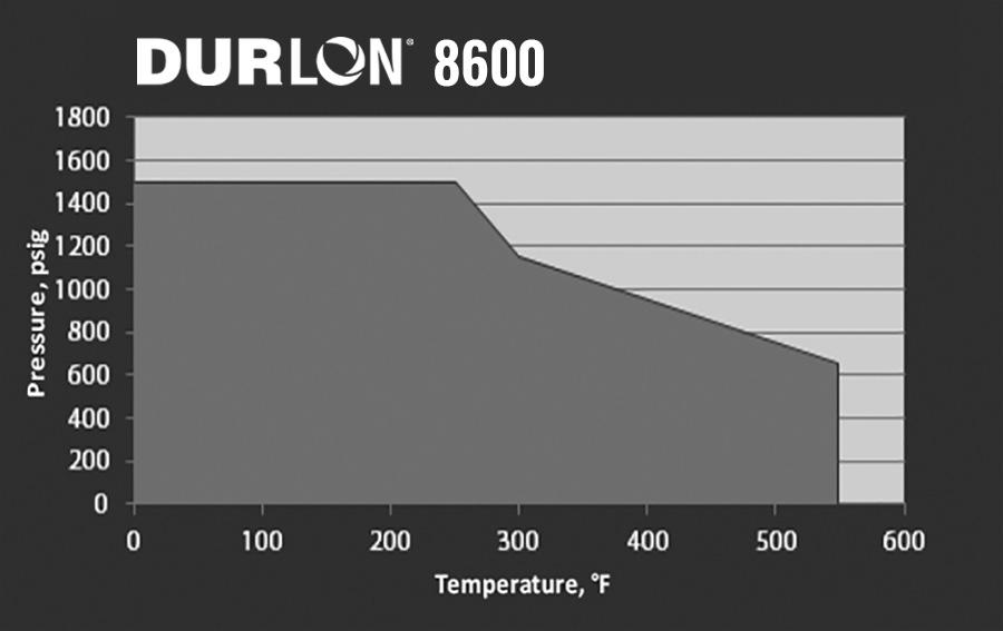
Durlon® 8600 is a quality compressed sheet gasket material for use in process industries including pulp & paper, power, petrochemical as well as general industry where a “white” gasket material is often required when working with food & beverage, pharmaceutical and plastics.
INDUSTRY APPLICATIONS:
Aramid/Inorganic with SBR Rubber Binder
Compressed Non-Asbestos Gasket Material
ASTM F104: F712440-A9B3E24K5L152M5
Physical Properties
Color
Fiber System
Nitrogen Sealability ASTM 2378, cc/min 0.05
Fluid Resistance, ASTM F146
IRM 903 Oil 5hrs at 300°F
Thickness Increase, %
Weight Increase, %
ASTM Fuel B 5hrs at 70°F Thickness Increase, %
Increase,

Durlon® 8700 is a high performance gasket material for use in processes requiring a neoprene (CR) bonded sheet and has excellent hand and die cutting characteristics. This product has excellent resistance to oils, non-aromatic solvents and many refrigerants.
INDUSTRY APPLICATIONS:

Note: ASTM properties are based on 1/16” sheet thickness, except ASTM F38 which is based on 1/32” sheet thickness. This is a general guide only and should not be the sole means of accepting or rejecting this material. The data listed here falls within the normal range of product properties, but should not be used to establish specifications limits nor used alone as the basis of design. For applications above Class 300, contact our technical department.
Aramid/Inorganic with CR Rubber Binder Compressed Non-Asbestos Gasket Material
ASTM F104: F712330-A9B5E45K5L153M5
Physical Properties Color
Fluid Resistance, ASTM F146
IRM 903 Oil 5hrs at 300°F
Thickness Increase, % Weight Increase, %
ASTM Fuel B 5hrs at 70°F
Increase, %
Increase, %
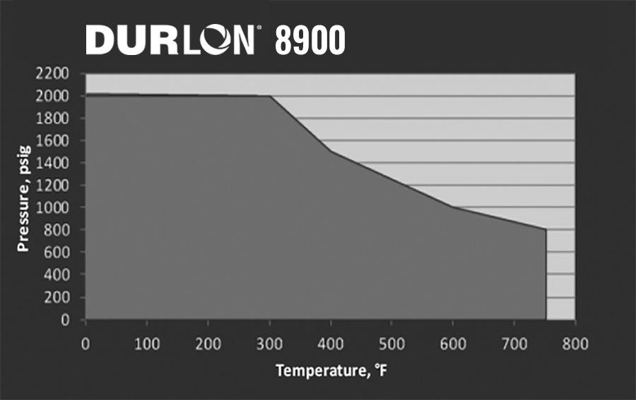
A premium grade material for service conditions to 496°C (925°F) and continuous operating temperatures of -40°C to 400°C (-40°F to 752°F). Durlon® 8900 is ideal for saturated and superheated steam, oil, dilute acids and alkalis, hydrocarbons and solvents.
INDUSTRY APPLICATIONS:
• Chemical Processing • Food & Beverage • Mining
Reach Declaration
ASTM properties are based on 1/16” sheet thickness, except ASTM F38 which is based on 1/32” sheet thickness. This is a general guide only and should not be the sole means of accepting or rejecting this material. The data listed here falls within the normal range of product properties, but should not be used to establish specifications limits nor used alone as the basis of design. For applications above Class 300, contact our technical department.
Aramid-Graphite with NBR Rubber Binder
Compressed Non-Asbestos Gasket Material
ASTM F104: F712120-A9B2E21L101M6 8900
Physical Properties
Color
Fiber System
Binder
Black
Aramid/Inorganic
(752°F) Pressure, Max, bar (psi) 138 (2,000) Density, g/cc (lbs/ft3) 1.6 (100)
Compressibility, % 7-17
Recovery, % 50
Creep Relaxation, % 15
Nitrogen Sealability
Fluid Resistance, ASTM F146
IRM 903 Oil 5hrs at 300°F
Thickness Increase, %
Weight Increase, %
ASTM Fuel B 5hrs at 70°F Thickness Increase, % Weight Increase, %
ASTM F147
Stress Relaxation, DIN 52913 @ 7,252psi (50 MPa) 16 hr @ 347°F (175°C) 16
PTFE (Polytetrafluoroethylene)
Durlon® filled PTFE gaskets/sheets are exclusively manufactured at Triangle Fluid Controls Ltd. in Belleville, Ontario, Canada. Our compression molded and skived manufacturing process allows for the best control of physical properties and performance characteristics compared to other manufacturing processes.
PTFE (polytetrafluoroethylene) has excellent chemical resistance and its unique properties lends itself well for use in a variety of industrial, manufacturing, and engineering facilities. The superb chemical resistance and tolerance to vast temperature gradients has not only improved the efficiency of many industries, but the safety for the employees that work around those conditions as well.
ADVANTAGES OF USING FILLED PTFE COMPOUNDS:
• Excellent chemical resistance
• Wide range of service temperature
• Excellent dielectric properties
• Non-stick, low friction
• No embrittlement or aging
• Smooth surface finish can be achieved
• Non-wetting
• Outstanding corrosion protection
• Electrical insulation
• High thermal stability and flame resistance
• Resistance to weathering
• Food grade compliant
HYDROGEN FLUORIDE RESISTANCE
Hydrogen fluoride is a critical chemical used in many industries, including metal manufacturing and petroleum production. It’s also highly reactive and corrosive.
Given the serious health and environmental hazards associated with hydrogen fluoride, the Environmental Protection Agency (EPA) requires immediate reporting of any leaks; even a minor leak can result in plant shutdown, significantly affecting overall operations, downtime, labor needs, and costs.
The Hydrogen Fluoride Industry Practices Institute (HFIPI) publishes a Materials of Construction Guideline to help ensure the safest possible industrial use of hydrogen fluoride. Within this guide, PTFE is listed as a safe sealant for hydrogen fluoride.
COMMON GRADES OF PTFE:
Virgin PTFE
“Virgin PTFE” (PTFE without a filler) is one of the most chemically inert materials known and is used in many different applications and industries.
Glass Filled PTFE
Virgin PTFE with 20-30% Glass filler which dramatically increases compressive strength and lowers deformation under load.
Carbon Filled PTFE
The addition of carbon to PTFE increases the compressive strength
and wear resistance. It provides good thermal conductivity and low permeability.
Barium Sulfate Filled PTFE
The addition of barium sulfate to PTFE offers excellent resistance to cold flow and creep, bolt-load retention, outstanding dimensional stability under thermal stress, and resists a variety of chemicals.
PROCESSING PTFE
Because PTFE is a thermoplastic and due to its high viscosity, it cannot be processed using conventional polymer processing techniques. PTFE is processed by cold shaping and followed by heat treatment (sintering) during which polymer particles fuse to form a solid molding.


PTFE is highly resistant to corrosion due to its chemical inertness. Unfortunately, that same chemical inertness prevents PTFE from being cross-linked like elastomers and is subject to the phenomenon of cold flow – otherwise known as “creep”. To reduce and diminish cold flow, additives are introduced during the preparation of PTFE compounds. Glass fillers found in Durlon® 9000 and 9000N gaskets, not only reduce creep but also maintain chemical inertness against aggressive and caustic chemicals but are still considered safe for use by food, drug, and medical services.


SKIVING
Durlon® PTFE is manufactured via skived method, vs our competitors that utilize the HS-10 calendar method. The calendered method has some downfalls such as sheet thickness tolerance and perhaps the main fall-back is that the sheet length can only be as long as the circumference of the roll - in most cases this is only 60” (1500mm).
Durlon® skived PTFE benefits feature tighter sheet tolerances and sheet lengths that can be cut in 60” increments. We offer ¹ 8” sheets in 60” x 60”, 60” x 120”, 60” x 180”, 60” x 300” and up to 60” x 110 linear feet if you truly required it. The benefit of longer or continual sheets can result in an increase of up to 30%* gasket cutting yield. *Based on gaskets size/qty.
Through our 3rd party testing of our Durlon® PTFE vs competitor calendered sheets, we can dispel the following myths about skived material: stratification of fillers, uneven disbursement of fillers, and tensile strength variation due to unidirectional compression loading.*Ask to see our data.
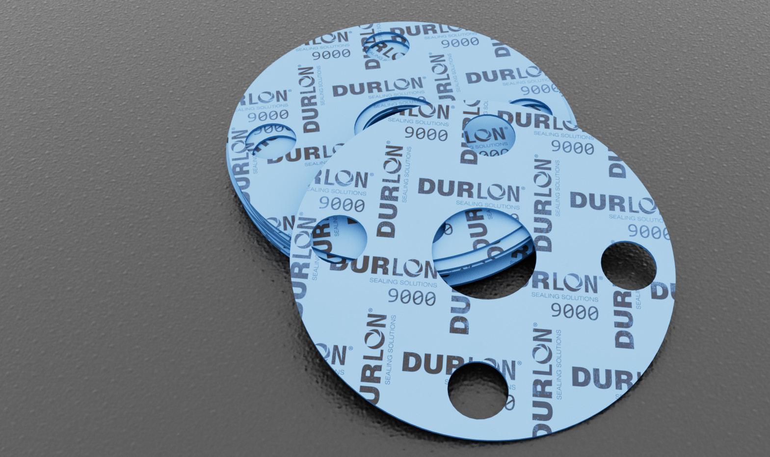
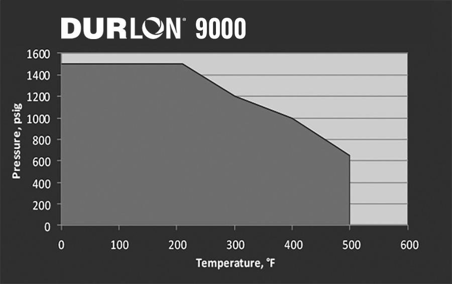
Durlon® 9000 is for use in general industrial applications where resistance to highly aggressive chemicals is required. In addition, the shape of the fillers does not allow wicking which can cause corrosion on flange surfaces.
INDUSTRY APPLICATIONS:
• Chemical Processing
• Food & Beverage
• General/Heavy Industry
• Marine
• Mining
BENEFIT:
• OEM Services
• Oil & Gas
• Petrochemical
• Pharmaceutical
• Power Generation
• Pulp & Paper
• Refining
• Water & Wastewater
Inorganic Filler with Pure PTFE Resins
Filled PTFE Gasket Material ASTM F104: F452111-A9B5E11K6M6
Physical Properties
Durlon® 9000 has a strong dielectric rating, making it ideal for isolation kit applications where PTFE sheet gaskets can be utilized.
Certifications
API 6FA* , 3rd Edition Fire Test Passed
USP for Plastic Class VI Met requirements - 121°C (250°F)
FDA Conforms to required 21 CFR 177.1550
TA-luft (VDI Guideline 2440) Approved Material
ABS-PDA & Pamphlet 95 Approved Material, chlorine institute
(EC) 1935/2004 & EU (10/2011) Approved Material
Sealability
2378, cc/min
Leakage, mbar .1 (m .5) TA-Luft (VDI 2440) iBar (14.5 psi) @180°C (392°F) 7.55 x 10⁻⁶
Volume Resistivity ASTM D257,
*6 inch Class 300. The test fixture was subjected to an external flame of 875°C (1607°F) average for 30 minutes. The measured leakage was 1.8 ml/min, where the max allowable limit is 1200 ml/min. For ¹ 8” material, reduce temperature by 20-30%
Note: ASTM properties are based on 1/16” sheet thickness, except ASTM F38 which is based on 1/32” sheet thickness. This is a general guide only and should not be the sole means of accepting or rejecting this material. The data listed here falls within the normal range of product properties, but should not be used to establish specifications limits nor used alone as the basis of design. For applications above Class 300, contact our technical department.
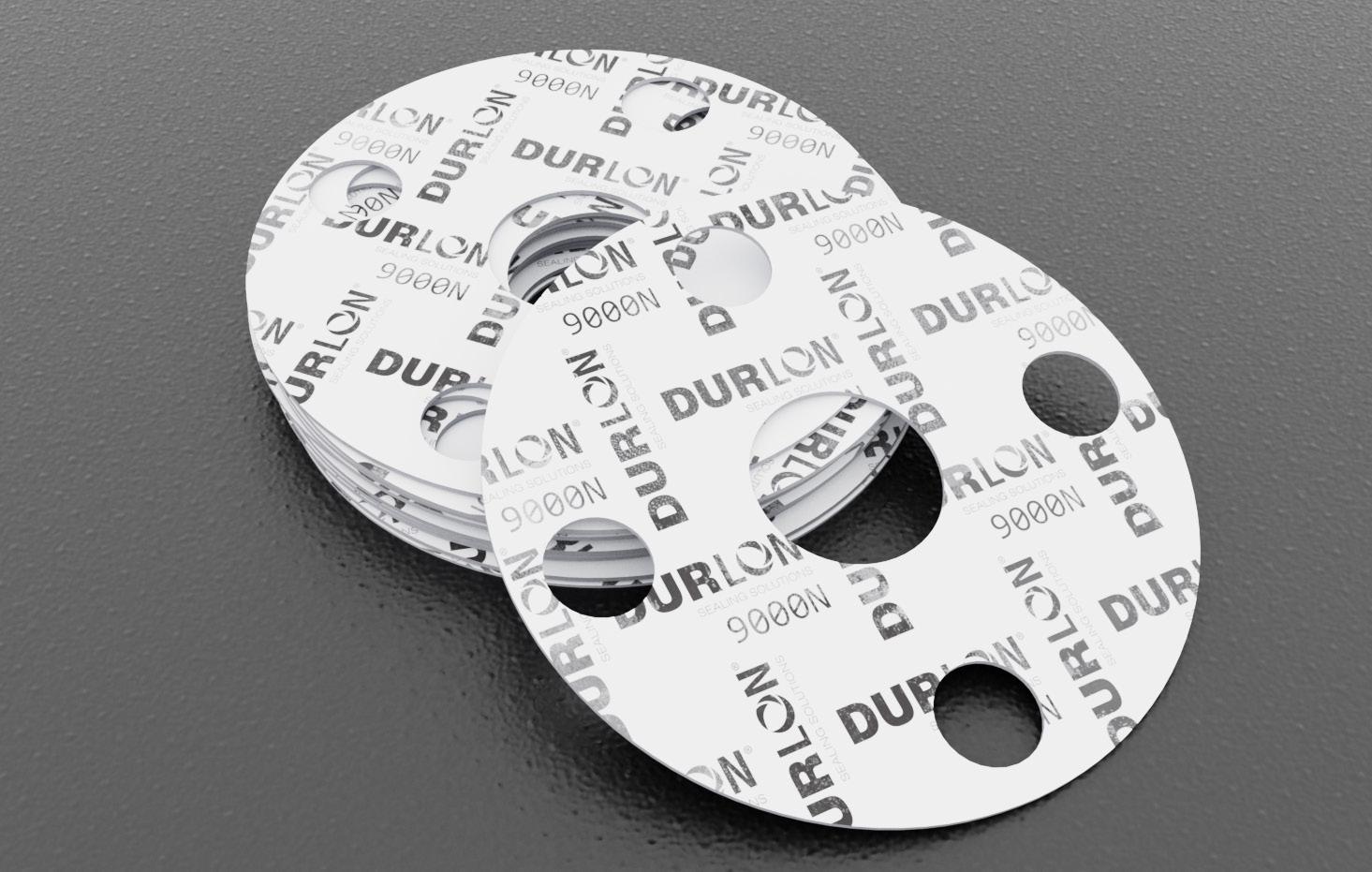
Durlon® 9000N is for use in general industrial applications where resistance to highly aggressive chemicals is required. In addition, the shape of the fillers does not allow wicking, which can cause corrosion on flange surfaces.
INDUSTRY APPLICATIONS:
• Chemical Processing
• Food & Beverage
• General Industry
• Marine
Certifications
• Mining • OEM Services
• Oil & Gas
• Pharmaceutical • Power Generation
• Pulp & Paper
• Water & Wastewater
9000N
Inorganic Filler with Pure PTFE Resins
Filled PTFE Gasket Material
ASTM F104: F452111-A9B5E11K6M6
Physical Properties Color
USP Class VI Met requirements for Plastic Class VI - 121°C (250°F)
FDA Conforms to the requirements of 21 CFR 177.1550 for food and drug contact
ABS-PDA & Pamphlet 95 Approved Material, chlorine institute
(EC) 1935/2004 & EU (10/2011) Approved Material

Note: ASTM properties are based on 1/16” sheet thickness, except ASTM F38 which is based on 1/32” sheet thickness. This is a general guide only and should not be the sole means of accepting or rejecting this material. The data listed here falls within the normal range of product properties, but should not be used to establish specifications limits nor used alone as the basis of design. For applications above Class 300, contact our technical department.

Durlon® 9002 is an adaptation of the original glass-filled formula to better meet extreme cryogenic demands and is readily available through the standard manufacturing process and requires no secondary heat or cleansing treatments prior to gasket cutting. Once gaskets are cut, traditional oxygen cleaning standards must be applied for safety.
Available as oxygen cleaned gaskets, bagged, labeled, and sealed according to the European Industrial Gases Association standard for Cleaning of Equipment for Oxygen Service.
INDUSTRY APPLICATIONS:
• Chemical Processing
• Marine (LNG)
Certifications
• Pharmaceutical
• Cryogenic
FDA Conforms to the requirements of 21 CFR 177.1550 for food & drug contact
BAM Oxygen Service: Gaseous & Liquid (Test Report)
LOX Mechanical Impact (ASTM G86 & ISO 21010)
Up to 260°C (500°F) at 52 bar (754 psi)
Zero reactions out of 20 at a test reaction frequency of 0%
RoHS Reach Declaration Compliant
DNV-GL Approved Material

9002
Inorganic Filler with Pure PTFE Resins
Filled PTFE Gasket Material ASTM F104: F452111-A9B5E11K6M6
Physical Properties
Note: ASTM properties are based on 1/16” sheet thickness, except ASTM F38 which is based on 1/32” sheet thickness. This is a general guide only and should not be the sole means of accepting or rejecting this material. The data listed here falls within the normal range of product properties, but should not be used to establish specifications limits nor used alone as the basis of design. For applications above Class 300, contact our technical department.
Durlon® 9200 is a filled PTFE gasket material used where resistance to highly aggressive chemicals is required. Barium sulfate fillers are homogeneously blended with pure PTFE resins to give Durlon® 9200 its physical and mechanical properties.
INDUSTRY APPLICATIONS:
• Chemical Processing
• Food & Beverage
• General/Heavy Industry
• Marine
• Mining
Certifications
• OEM Services
• Oil & Gas
• Petrochemical
• Pharmaceutical
• Power Generation
• Pulp & Paper
• Rail Tank Car
• Water & Wastewater
FDA Conforms to the requirements of 21 CFR 177.1550 for food & drug contact
TA-luft (VDI Guideline 2440) Approved Material
BAM Oxygen Service Approved Material
ABS-PDA & Pamphlet 95 Approved Material
(EC) 1935/2004 & EU Approved Material
Blow-Out & DVGW Approved Material

Barium Sulfate Filler with Pure PTFE Resins
Filled PTFE Gasket Material
ASTM F104: F451-A9B2M6
Physical Properties Color
Leakage Rate TA-Luft (VDI 2440), mbar .l/(s.m)
3535-6
Gasket Factors
Durlon® 9400 is a high performance filled PTFE gasket material designed for use in piping and equipment, chemical, and other general industrial applications where resistance to highly aggressive chemicals (including hydrofluoric acid) is required. Durlon® 9400 can also be used as the gasket of choice for anhydrous hydrogen fluoride (AHF) in railroad tank cars and a good alternative for use in plants where barium sulfate filled PTFE may not be suitable.
Hydrogen fluoride is a critical chemical used in many industries, including metal manufacturing and petroleum production. It’s also highly reactive and corrosive. Durlon® 9400 carbon-filled PTFE gaskets are built to endure the harshest exposure to hydrogen fluoride. This gasket provides superior sealing properties, and is both highly durable and flexible.
• Chemical Processing
• Food & Beverage
• Marine
• Mining
• OEM Services
Certifications
• Oil & Gas
• Petrochemical
• Pharmaceutical
• Power Generation
• Pulp & Paper
Carbon Filler with Pure PTFE Resins Filled PTFE Gasket Material ASTM F104: F452111-A9B5E11K6M6
Physical Properties
INDUSTRY APPLICATIONS: For ¹⁄8” material, reduce temperature by 20-30%
• Rail Tank Car
• Refining
• Water & Wastewater
• General/Heavy Industry
RoHS Reach Declaration Compliant
HFIPI - Materials of Construction Guideline Approved Material
Note: ASTM properties are based on 1/16” sheet thickness, except ASTM F38 which is based on 1/32” sheet thickness. This is a general guide only and should not be the sole means of accepting or rejecting this material. The data listed here falls within the normal range of product properties, but should not be used to establish specifications limits nor used alone as the basis of design. For applications above Class 300, contact our technical department.
Gasket Factors
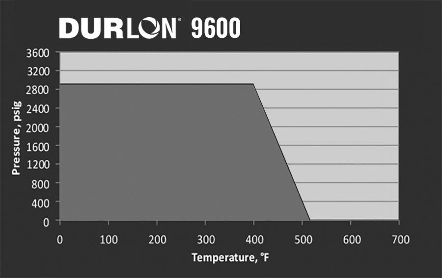
Durlon® 9600 is a biaxially expanded PTFE gasket, made with only pure PTFE resins, designed for use in process piping and equipment, in chemical, pulp and paper, food and beverage, and other general industrial applications, where resistance to highly aggressive chemicals is required.
Durlon® 9600 is also suitable for sealing flanges with irregular surfaces. It will not exhibit the cold flow problems associated with virgin PTFE, or the hardness problems of some filled PTFE products. It has excellent sealability, cuts easily and separates cleanly from flanges after use. This material is FDA compliant, ABS-PDA, USP Class VI, and TA-Luft certified.
Physical Properties Color
Certifications
FDA Conforms to the requirements of 21 CFR 177.1550 for food and drug contact
USP for Plastic Class VI Met requirements - 121°C (250°F)
RoHS Reach Declaration Compliant
ABS-PDA Certified Approved Material TA-Luft (VDI Guideline 2440) Approved Material
Refining INDUSTRY APPLICATIONS: Note: ASTM properties are based on 1/16” sheet thickness, except ASTM F38 which is based on 1/32” sheet thickness. This is a general guide only and should not be the sole means of accepting or rejecting this material. The data listed here falls within the normal range of product properties, but should not be used to establish specifications limits nor used alone as the basis of design. For applications above Class 300, contact our technical department.

The Durlon® 9645 product range offers a biaxially-oriented PTFE sheet solution that combines superior chemical resistance with exceptional sealing performance, making it an optimal choice for demanding industrial applications.
Engineered to perform across a broad temperature range from cryogenic conditions up to +260°C, Durlon® 9645 is suitable for handling aggressive media spanning the full pH spectrum (0 to 14). This advanced material is designed for applications requiring minimal creep and reliable seal integrity, particularly in scenarios where low leakage is critical, and conventional PTFE materials fail to meet the requirements.
Durlon® 9645 is designed with controlled microporosity and a closed-cell structure, delivering excellent compressibility and reliable sealability, even at low bolt torque. The compressible PTFE surface layers make Durlon® 9645 ideal for warped, pitted, or scratched flanges, as the microcellular layer conforms effectively to surface irregularities.
The rigid PTFE core minimizes cold flow and creep, significantly enhancing durability and long-term performance. It also improves handleability and simplifies installation, particularly on large-diameter flanges or in hardto-reach locations. Durlon® 9645 is an excellent choice for low torque applications, such as glass-lined flanges and equipment, where traditional solutions often struggle to perform.
Moreover, Durlon® 9645 is compatible with a wide range of chemicals, including strong acids and aggressive caustics, ensuring versatility across various industries. This material is also a superior alternative to envelope gaskets, offering robust sealing performance with added durability and ease of use.
INDUSTRY APPLICATIONS:
• Chemical Processing
• Food & Beverage
• General Industry
• Marine
• Mining • OEM Services
• Oil & Gas
• Pharmaceutical • Power Generation • Pulp & Paper • Water & Wastewater
NEW PRODUCT 9645
Microcellular PTFE with Rigid PTFE core ASTM F104: F497130E21M4
Physical Properties
Color
Certifications
FDA
(VDI Guideline 2440)
Conforms to the requirements of 21 CFR 177.1550 for food and drug contact

Durlon® Virgin PTFE gasket material is a high performance PTFE product designed for use in piping and equipment in chemical and other general industrial applications where resistance to highly aggressive chemicals (including hydrofluoric acid) is required.
FEATURES:
• better physical properties
• good electrical insulator
• FDA approved
Durlon® Virgin PTFE is made with only pure PTFE resins. It has excellent sealability characteristics, cuts easily and separates cleanly from flanges after use. Durlon® Virgin PTFE demonstrates high dielectric strength.
INDUSTRY APPLICATIONS:
• Chemical Processing
• Food & Beverage
• Pharmaceutical
Virgin PTFE
100% Pure PTFE Gasket Material
Physical Properties
Color White
Material Skived PTFE
(-350°F)
(500°F)
Pressure, Max, bar (psi) 86 (1,250)
Density, g/cc (lbs/ft3) 2.1 (135)
Compressibility, % 12-20
% 35-40
Relaxation, % 40 Nitrogen Sealability ASTM 2378, cc/min 0.01 Tensile Strength, MPa (psi) 19.3 (2,800)
Certifications
FDA Conforms to the requirements of 21 CFR 177.1550 for food and drug contact (Applies to Skived grade only)
RoHS Reach Declaration Compliant

Durlon® Joint Sealant (PTFE Adhesive) is a highly fibrillated expanded PTFE form-in-place sealant for gasketed joints and conforms to FDA requirements.
Supplied on spools, Durlon® Joint Sealant comes in various thicknesses with a high quality adhesive backing to ease in installation; making it ideal for worn flanges of all sizes and is not dependent on flange dimensions. It exhibits flexibility, compressibility, and stability under high temperature while maintaining high tensile strength. Another feature of Durlon® Joint Sealant is its chemically inert properties which resists creep relaxation, resulting in the maintenance of a tight seal.
Durlon® Joint Sealant is made with only 100% pure PTFE resins and exhibits the same chemical resistance of virgin PTFE.
Joint Sealant
100% Pure Expanded PTFE Gasket Material
Recommended Usage Chart- Imperial (Metric)
2” - 4” (5cm - 10cm)
- 16” (25cm - 41cm)
- 24” (46cm - 61cm)


(.6cm) 5” - 8” (13cm - 20cm)
(1cm)
(1.6cm) 26” - 48” (66cm - 122cm)
(1.9cm) 48” (122cm) and higher 1” (2.5cm)


NOTE: Step-by-step “Installation Instructions” downloadable PDF is available at: www.durlon.com/resources/technical-references/

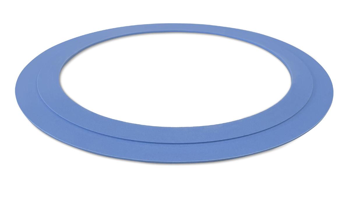
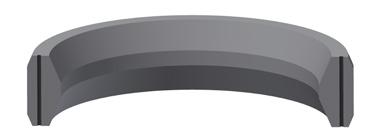
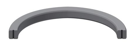
Our next level of manway sealing for the rail car industry features a single “Universal Style” gasket that can accommodate several model sizes. The flexibility of the SecureSnap™ manway gasket enables the user to install the gaskets more quickly than the conventional gasket. Flexible tabs easily snap into the groove bottom, eliminating the need for tight tolerances associated with conventional style gaskets.
Inorganic Filler with Pure PTFE Resins
Filled PTFE Gasket Material
ASTM F104: F452111-A9B5E11K6M6
Physical Properties
Color Blue
Filler System Inorganic
Temperature:
Certifications
API 6FA* , 3rd Edition Fire Test Passed
USP for Plastic Class VI Met requirements - 121°C (250°F)
FDA Conforms to required 21 CFR 177.1550
TA-luft (VDI Guideline 2440) Approved Material
ABS-PDA & Pamphlet 95 Approved Material, chlorine institute
(EC) 1935/2004 & EU (10/2011) Approved Material
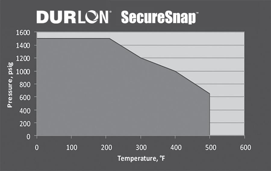

The flexibility of the SecureSnap™ manway gasket also renders the gaskets more versatile than the conventional gasket. The SecureSnap™ gasket will accommodate more than one style of manway system (dependent on end user approval) allowing distributors to stock one size of gasket for multiple manway designs, therefore reducing inventory and overall cost. *6 inch Class 300. The test fixture was subjected to an external flame of 875°C (1607°F) average for 30 minutes. The measured leakage was 1.8 ml/min, where the max allowable limit is 1200 ml/min.
Nitrogen Sealability
ASTM 2378, cc/min 0.01
Leakage, mbar .1 (m .5)
TA-Luft (VDI 2440)
(138)
iBar (14.5 psi) @180°C (392°F) 7.55 x 10⁻⁶
Volume Resistivity
ASTM D257, ohm-cm 1.0 x 10⁵
Dielectric Breakdown
ASTM D149, kV/mm (V/mil) 16 (406)


The above illustrates a 3” 150# Full Face gasket using FEA analysis to show the applicable stresses that are being applied to the gasket while bolted up in the flange.
Acid piping systems are designed for many years of continuous operation and are subject to thermal cycling and aggressive chemical corrosion making it important to use the proper gasket.
Our single-piece construction Step Ring Gasket is custom machined from Durlon® 9000 - a filled PTFE gasket material compatible with sulfuric acid in all concentrations, and has excellent physical properties: sealability and recovery from extreme thermal cycling and vibration.
With recommended installation and torqueing procedures, Durlon® 9000 Step Ring Gaskets normally do not need to be re-torqued, and will not
Reduced Contact Area Full Face Gasket PTFE & Compressed Non-Asbestos Gasket Material
RCA® is a registered trademark of Gasket Resources Inc.
Durlon® RCA® sealing system combined with Durlon® PTFE styles can replace standard full gaskets in FRP, PVC and other non-metallic and metallic pipe flanges where a low stress gasket is required. The RCA® configuration can be cut from standard PTFE & CNA sheets resulting in a cost savings versus other low stress gaskets.
AVAILABLE
MATERIALS: ¹⁄16” & ¹ 8” Durlon® PTFE styles and Compressed Non-Asbestos styles
AVAILABLE SIZES: 1-24” Class 150 Full Face gaskets
• For FRP, PVC, Glass-Lined or steel flanges where a low stress gasket is required
• Reduced contact area, lower sealing stress, and significant cost savings
• Alignment guides included for easy positioning during installation
• Identification tabs extend beyond the flange OD for easy identification once bolted
• Custom sizes and designs are available
Used extensively in Sulfuric Acid Plants often found in Phosphate Refineries 9000 Step Ring Gasket
'cold flow' into the pipe ID or outside the flange OD. Tests have shown that Durlon® 9000 Step Ring Gaskets can retain up to 7% more load than traditional Fawn* PTFE Step Ring Gaskets which translates into a tighter seal, over a longer period of time.
*Traditional Fawn PTFE Step Ring Gasket design requires two different sized 1.5mm (1/16”) thick ring gaskets to be bonded together with some form of industrial strength adhesive. Over time the adhesive breaks down due to thermal and chemical exposure.
APPLICATIONS:
• Class 150 RF Floating (Lap Joint) Flanges
• Mondi™ Ductile Iron Sulfuric Acid Piping

Metallic & Semi-Metallic Gasketing
Durlon® metallic gaskets are manufactured from a combination of metals and designed to withstand extreme temperatures, pressures and chemical exposure. Available in standard and custom configurations, these rugged metal gaskets are made of a wide range of materials to accommodate all types of process applications.
These gaskets are designed to work by ”initial line contact” or a wedging action between the flange and the gasket.
Durlon® semi-metallic gaskets include both metallic and nonmetallic components, either containing a metal core with sealing materials on both flat surfaces, or a pliable core encased in a thin metallic casing. These configurations are most popular, and available in a wide variety of styles and sizes. They can typically be fabricated of any metal which is available in thin strip or sheet, and that can be welded. Therefore, they can be used against virtually any corrosive medium dependent upon the choice of the metal and filler or facing material.
Our computer-aided manufacturing process uses rigorous quality control programs to ensure premium quality product performance. The metallic component gives the gasket superior structural integrity, while the non-metallic element ensures superior sealing. To be able
to achieve an effective seal, proper gasket selection must occur with metallic gaskets. The following elements must be considered when determining the correct gasket for the application.
TEMPERATURE
Most gaskets consist of two or more components or ingredients. The overall temperature resistance of a gasket is determined through analysis of the upper and lower limits for each component. There are two parts that need to be considered and verified when selecting the correct gasket material. The first part is to verify the metal component used to ensure the maximum temperature for the material is not exceeded. Secondly, the maximum temperature rating for the filler or facing material must be verified to ensure it is not exceeded. In most cases the filler or facing material will be the sacrificial element and will be the governing factor when selecting a semi-metallic gasket.
CHEMICAL COMPATIBILITY
The gasket must be resistant to chemical corrosion or chemical attack. The rate of corrosion is dependent on the time, temperature, and concentration of the media and must be considered when selecting both the gasket metallurgy and filler or facing material. For chemical resistance information of metals and semi-metallic gaskets, see pages 64-71.
FLANGE COMPATIBILITY
The flange itself must be designed so that it can apply a sufficient amount of clamping force to ensure the flange serrations are biting into, or seating the gasket. Flange materials also need to be verified against the specified metallurgy in semi-metallic gaskets. If left unverified, it is possible for galvanic type corrosion to occur due to dissimilar metals. In the use of RTJ gaskets, the gasket must deform enough to create an effective seal. If the material of the gasket is harder than the flange, it will damage the flange; hence the material hardness is critical when dealing with RTJ flanges and gaskets.
GASKET SEATING STRESS
The gasket seating stress is the minimum force required to compress the gasket so that it forms an effective seal while resisting the blowout or internal pressure of the system. Seating stress must also be taken into consideration with both the gasket type and flange surface finish. The minimum and maximum seating stresses are product specific and recommended by the manufacturer, the table below shows the recommended minimum and maximum stresses for Durlon® metallic gasketing products.
Gasket Type/Style
*HT1000® is a registered trademark of Triangle Fluid Controls Ltd.
NOTES:
1. Minimum gasket stresses shown do not necessarily ensure any specific level of leak tightness. They generally reflect minimum seating stresses found in published documents. Specific manufacturer’s data may fall outside of this range.
2. Maximum gasket stress shown may be dependent upon gasket materials used.
3. The gasket stresses shown above are not specific to any given leak tightness class (ie. T1, T2, T3, etc.)
4. Maximum gasket stress based on gasket diameter.
5. Contact tech@durlon.com with application specific details.
6. Minimum seating stress based on ring material selected.
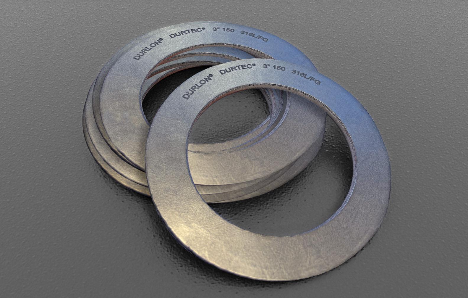
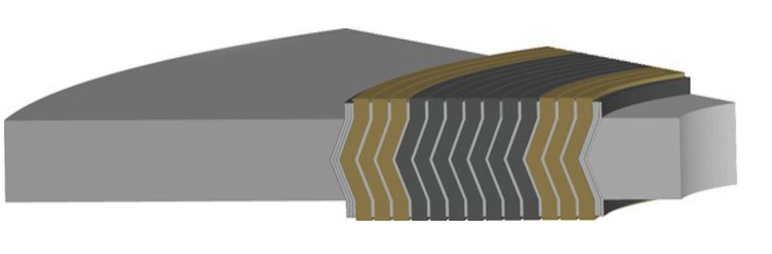
Durlon® Durtec® gaskets are made with a specially engineered machined metal core that is bonded on both sides with soft covering layers, typically flexible graphite. The core is produced by proprietary technology that allows the finished gasket to have the best possible mechanical support function. The Durtec® core is virtually uncrushable, unlike conventional corrugated metal core gaskets. The precision construction guarantees that Durlon® Durtec® gaskets will have excellent sealing characteristics even under low bolt loads.
The Durtec® gasket is designed to withstand high temperatures and pressures, to be blowout resistant, to be fire safe, and to resist toxic and or corrosive chemicals for such applications as: pipeline flanges, valves, small & large pressure vessels, heat exchangers, towers, and tanks.
INDUSTRY APPLICATIONS:
• Water & Wastewater
• Oil & Gas
• Mining
• Food & Beverage
• OEM Services
• Petrochemical
• Power Generation
• General Industrial
SIZE, TYPES & MATERIALS:
• Standard ASME, DIN, JIS and BS EN sizes
• Non-standard flanges ½” through 157” diameter
• Marine
• Chemical Processing
• Pulp & Paper
Durtec®
Specially Engineered Metal Core Technology
Durtec® is a registered trademark of Triangle Fluid Controls Ltd.
Physical Properties*
Temperature: Min Max Continuous, Max
pH range, Room Temp. 0-14 Pressure: Max, bar (psi)
*Depends on facing material and metallurgy of core.
(-328°F)
(1,832°F)
(1,200°F)
Note: Data shown above is for Inconel® 625 core and HT1000® covering layers.
Certifications
Fire Test**
API 607, 4th edition with Exxon modifications
RoHS Reach Declaration Compliant
**Passed modified API 607 fire test and meets the requirements of Shell Specification MESC SPE 85/203 & PVRC SCR Flexible Graphite Spec for FG 600 material.
Gasket Factors
• Standard core material is 316L stainless steel. Other core materials: SS304, SS321, SS316Ti, Monel®, Titanium, Hastelloy® & Alloy 20 can be manufactured to your specifications on request
• Alternate facing material is available upon request. Popular materials include Durlon® 9600 expanded PTFE (ePTFE), mica & ceramic
HEAT
EXCHANGER SHAPES
We can provide almost any configuration of heat exchanger type gasket utilizing our Durlon® Durtec® technology.
• Anywhere fire safety is a concern
• High temperature
• Low available assembly loads
• Heavy vibrations
• Extreme temperature fluctuations
• Remote field applications
• Large diameter gasket replacement
API 607 FIRE TEST:
• Average bolt torque loss (with no adjustments): Upstream 45%; Downstream 33%
• Fire, Cool-Down & Post-Burn: Combined Leak Rate (2 gaskets) 0 mL/min at 30 psig avg. where the allowable leakage rate is 150 mL/min.
• Exxon additional post burn leakage test: Combined Leak Rate (2 gaskets) with no flange bolt re-torques at any test pressure 0 mL/min at 30 psig, 0mL/min at 50 psig, 0 mL/min at 100psig and, 0mL/min at 200 psig where the allowable combined leakage rate is 150 mL/min.

Durlon® Flexible Graphite is unaffected by heat over a wide range of temperatures. It exhibits low electrical resistivity and high thermal conductivity and is suitable for cryogenic temperatures and is available in several styles.
These include homogeneous sheet and laminated styles with various types of core materials. Durlon® Flexible Graphite can also be special ordered with various inhibitors, grades of graphite, and core materials to suit specific critical applications.
INDUSTRY APPLICATIONS:
• Chemical Processing
• General Industry
• OEM Services
• Oil & Gas
• Petrochemical
• Power Generation
• Refining
CHARACTERISTICS AND BENEFITS:
• Impermeable to gases and liquids
• Suitable for service over a wide range of pressures and temperatures
• Resists thermal shock
-
• Maintains excellent sealability
• Does not age, shrink or harden
• Seals easily under low to moderate bolt loads
• High chemical resistant
Flexible Graphite
Homogeneous, 316SS Foil Insert 316SS Tang Insert, 316SS Multilayer
*More thicknesses available by special order, depending on material.

FGS95: Standard industrial grade sheet containing no binders or resins. Mainly used in industrial applications such as oil refineries, power plants and chemical process plants.
FGM316 - Physical Properties
F868-9FMF2
FGL316: Standard industrial grade sheet laminated with an adhesive bond on both sides of a 0.002” thick 316 stainless steel foil core. This product is used where high performance and handling are important.
FGT316: Standard industrial grade sheet mechanically bonded on both sides of a 0.004” thick 316 stainless steel tang core. This product is used where stresses and pressures are high and improved handling is important.
FGM316: Inhibited grade sheet laminated with multiple layers of 0.004” thick 316 stainless steel foil core. This product is used in applications with high mechanical stress or pressure, above average burst resistance, exceptional rigidity, and suitable to cut gaskets with narrow strips.
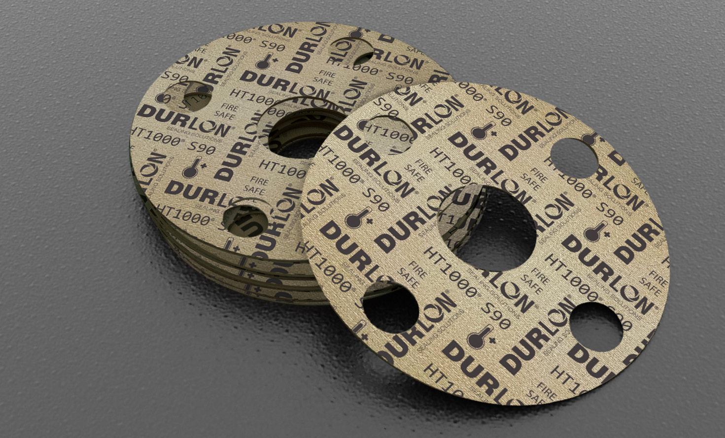
Durlon® HT1000® consists of phlogopite mica paper impregnated with an inorganic binder at less than half the binder amount found in vermiculitephyllosilicate filled products. This lower binder content allows for superior weight retention, less than 5% weight loss at 800°C (1,472°F), and results in ultimate extreme temperature sealing performance up to 1,000°C (1,832°F).
Durlon® HT1000® characteristics allow for it to be used as a sealing material on its own or combined with various carrier media in heat exchangers, exhaust manifolds, and other equipment commonly found in the refinery, power generation, and chemical industries.
Phlogopite mica is a non-toxic naturally occurring hydrated silicate of potassium and magnesium with a lamellar and non-fibrous structure. It is flexible, has a high tensile strength, can withstand substantial mechanical pressure perpendicular to the lamellar plane, is chemically resistant, fireproof, infusible, incombustible, non-flammable, and is a known alternative to asbestos.
INDUSTRY APPLICATIONS:
• General Industry
• Marine
• Mining • OEM Services • Petrochemical • Power Generation • Refining
Certifications
Fire Test
API 607, 4th edition with Exxon modifications
RoHS Reach Declaration Compliant
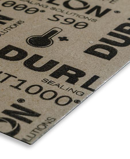
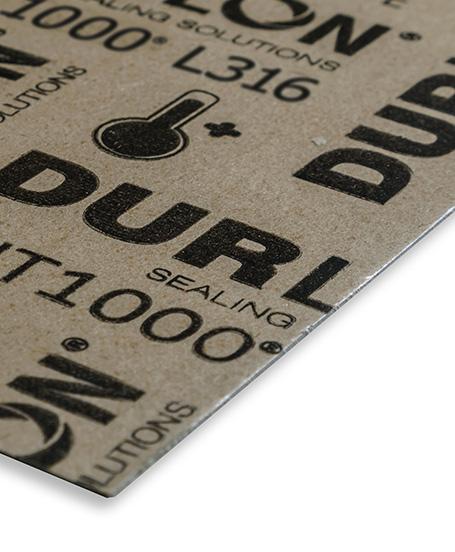
Durlon® HT1000® sheets and cut gaskets are available in 3 sheet forms:
S90: Phlogopite mica paper impregnated with an inorganic binder and no carrier.
L316: Phlogopite mica paper impregnated with an inorganic binder laminated with a 0.002” thick 316 stainless steel carrier.
T316: Phlogopite mica paper impregnated with an inorganic binder laminated with a 0.004” thick 316 stainless steel perforated carrier.

HT1000®
Phlogopite Mica with Silicone Binder S90, L316, T316
HT1000® is a registered trademark of Triangle Fluid Controls Ltd.
Physical Properties*
Color
Material
Temperature:
Pressure, Max, bar (psi) Style S90 Styles L316/T316 5 (73) 40 (580)
Density, g/cc (lbs/ft3) 1.9 (119)
Compressibility, % ASTM F36J 18-25
Recovery, % ASTM F36J 39-43
Volume Resistance, (Ω/cm) IEC 60093 @ 23ºC @ 500ºC ~1015 ~1010
Weight Loss @ 800°C, % DIN 52911 ≤ 5
Thermal Conductivity, W/(m.K) ASTM D5470-2017 @23ºC @600ºC ~0.20 ~0.30
Dielectric Strength, (kV/mm) IEC 60243 ~14
Flamability rating UL94 V-0
* The above table refers to Style S90 properties unless otherwise specified.
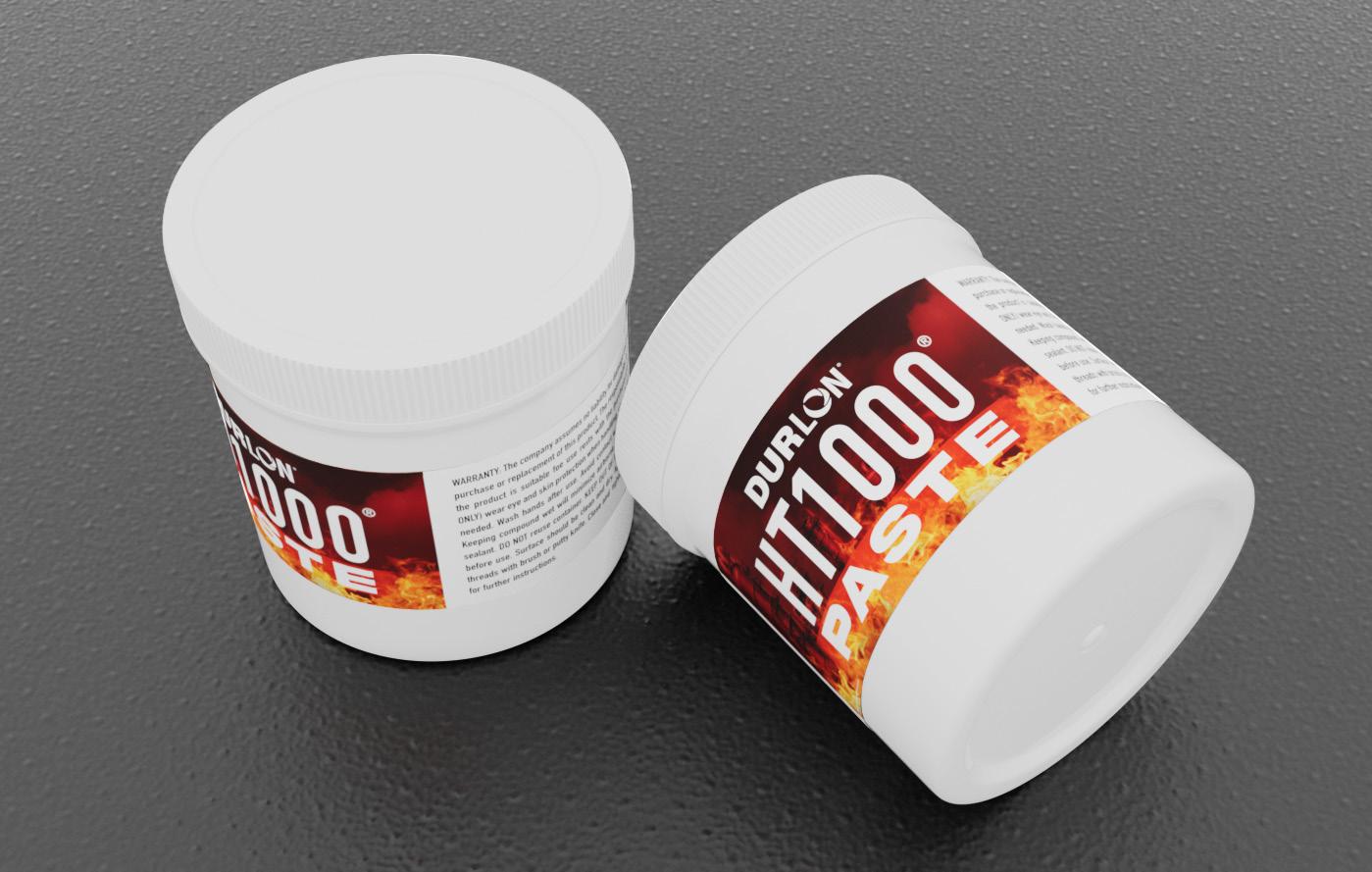
Durlon® HT1000® Paste is a sealing compound designed to be used in conjunction with our HT1000® sheet material specifically for large dovetail gaskets. The paste allows end users to create larger diameter gaskets using cost effective dovetail gasket segments. The HT1000® Paste allows end users to eliminate possible leak paths of traditional dovetail gaskets, while providing end users the one piece gasket construction and lower leakage rates similar to one-piece gasket.
AVAILABILITY: 170 g (6 oz) and 90 g (3.2 oz) containers.
PASTE USAGE GUIDE:
HT1000® Paste is designed for use with HT1000® dovetailed gaskets.
Recommended Amount:
5 grams (0.18 oz) per inch of gasket cross-section per segment.
Example Calculation:
• Gasket Size: 60” ID x 66” OD (Cross-section: 3”)
• Dovetails: 6 segments
• Paste Needed*: 5 g/in/segment × 3 in × 6 segments = 90 g (3.2 oz)
*Basedonsupplierinputandinternalexperimentation.
SHELF LIFE:
6 months in unopened container from the date it was packaged.
INSTRUCTIONS:
1. Make sure gasket segments are aligned and laying flat pre-assembled. Ensure that both the gasket and flange are free of debris, oils, and grease.
2. Open container of HT1000® Paste and apply a thin, even layer to the dovetail portion of the gasket, using a disposable brush or putty knife, smoothing out any uneven portions.
3. Assemble flange and tighten bolts according to gasket manufacturer’s recommendations (torque, bolt-up method, etc.).
4. HT1000® Paste will begin to cure in service (Please see applicable Curing Time Chart to the right).
HT1000® Paste
High Temperature Sealing Compound
HT1000® is a registered trademark of Triangle Fluid Controls Ltd.
Curing Time Chart
or
Note: In high pressure gasket sealing applications or if ambient pressure testing is being performed, it is recommended that the HT1000® Paste be pre-cured with a heat source such as a heat gun or oven if available prior to putting the gasket into pressurized service.
STORAGE: Store in closed container in a cool, dry place (refrigerate for best shelf life). Keep away from open flames.
WARRANTY: The company assumes no liability for damage caused by this product other than purchase or replacement of this product. The responsibility for determining whether or not the product is suitable for use rest with the purchaser.

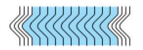
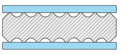
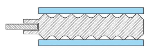
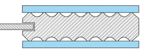
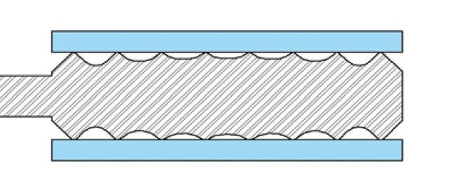
Durlon® CFG is a corrugated flexible graphite gasket material designed for severe service conditions. The proprietary design of the corrugations gives Durlon® CFG superior sealing and recovery characteristics for tough conditions in the refining, chemical, petrochemical, and pulp & paper industries. Durlon® CFG is suitable for service in steel, oil, mild alkalis, mild acids, hydrocarbons, and solvents.
Durlon® CFG consists of flexible graphite laminated with an adhesive bond on both sides of a corrugated 316 stainless steel core. For consolidation of inventories and applications standardization, Durlon® CFG is available for all applications in 3⁄32” (2.4mm) thickness. (¹⁄16” and ¹⁄8” thickness is also available.)
INDUSTRY APPLICATIONS:
Water & Wastewater
Oil & Gas
Food & Beverage
Pulp & Paper
Corrugated Flexible Graphite Gasket CFG
ADVANTAGES:
• Recovery/Spring-Back characteristics for excellent sealing and thermal cycling
• Blowout Resistant - Metal core counteracts internal pressure spikes
• Superior Emissions Control - Nitrogen Sealability (ASTM F2378) <0.01 cc/min
• Easy to handle, easy to install
• Seals tightly with lower bolt loads vs. SWGs
MATERIALS:
• Alternate facing material is available upon request. Popular materials include Durlon® 9600 expanded PTFE (ePTFE), mica & ceramic
DRI-ETG SWG Certifications
Fire Test
Fire Test
Fire Test
API 6FB, Fourth Edition 2019,Type 1 (Onshore Test)
API 6FB, Fourth Edition 2019,Type 2 (Offshore Test)
API 607, 4th Edition with Exxon Modifications
Extreme Temperature Gaskets
SWG/Durtec®/Kammprofile
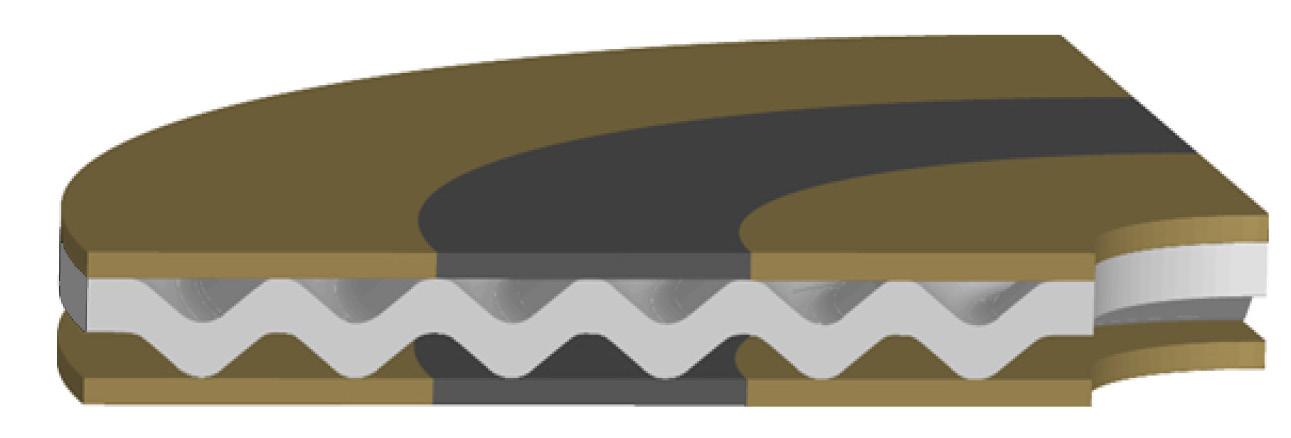
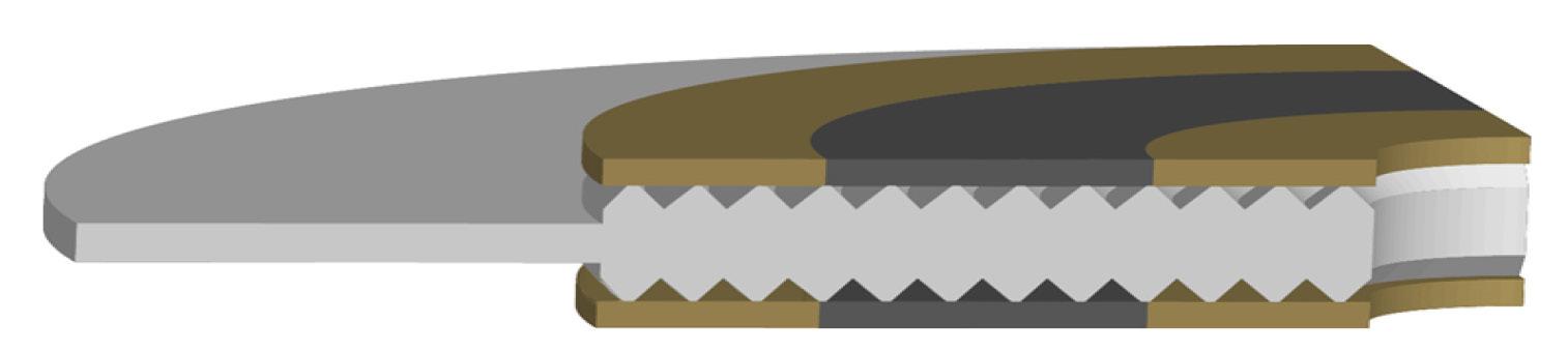
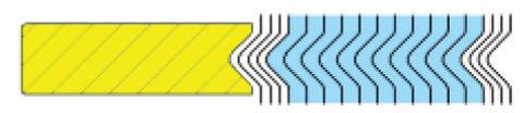
Durlon® Extreme Temperature Gaskets (ETG) have been engineered to provide the preeminent solution to sealing gasketed joints having exposure to high temperatures, typically greater than 650°C (1,200°F) and up to 1,000°C (1,832°F). At extreme temperatures, flange assembly torque retention is the key component to maintaining a tight seal. Durlon® ETG combines an oxidation boundary material with the excellent stability and sealing characteristics of flexible graphite in order to preserve seal integrity and retain the initial assembly torque.
Durlon® ETG’s engineered design principle is focused around providing oxidation protection zones around the central oxidation inhibited flexible graphite sealing component. Standard industrial grade flexible graphite typically begins to rapidly oxidize at around 650°C (1,200°F). By adding oxidation inhibitors to the graphite, the rate and amount of oxidation can be significantly reduced, thus extending the seal life of the material. However, oxidation can still occur and at extreme temperatures, it can be fatal to the integrity of the joint.
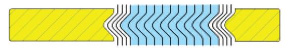
Durlon® ETG adds an inner and outer protection boundary in the form of a mica-phyllosilicate based sealing material called Durlon® HT1000® which consists of phlogopite mica paper impregnated with an inorganic binder at less than half the binder amount found in a typical vermiculite-phyllosilicate filled product. This lower binder content allows for superior weight retention and results in ultimate extreme temperature sealing performance.
INDUSTRY APPLICATIONS:
• Mining
• Power Generation
• General/Heavy Industry
• Marine
• Refining
• Chemical Processing
Durtec® ETG
K40-ETG Kammprofile
The Durlon® ETG’s design is the sealing industry’s current best available technology for effectively sealing extreme temperature applications.
DRI-ETG SWG
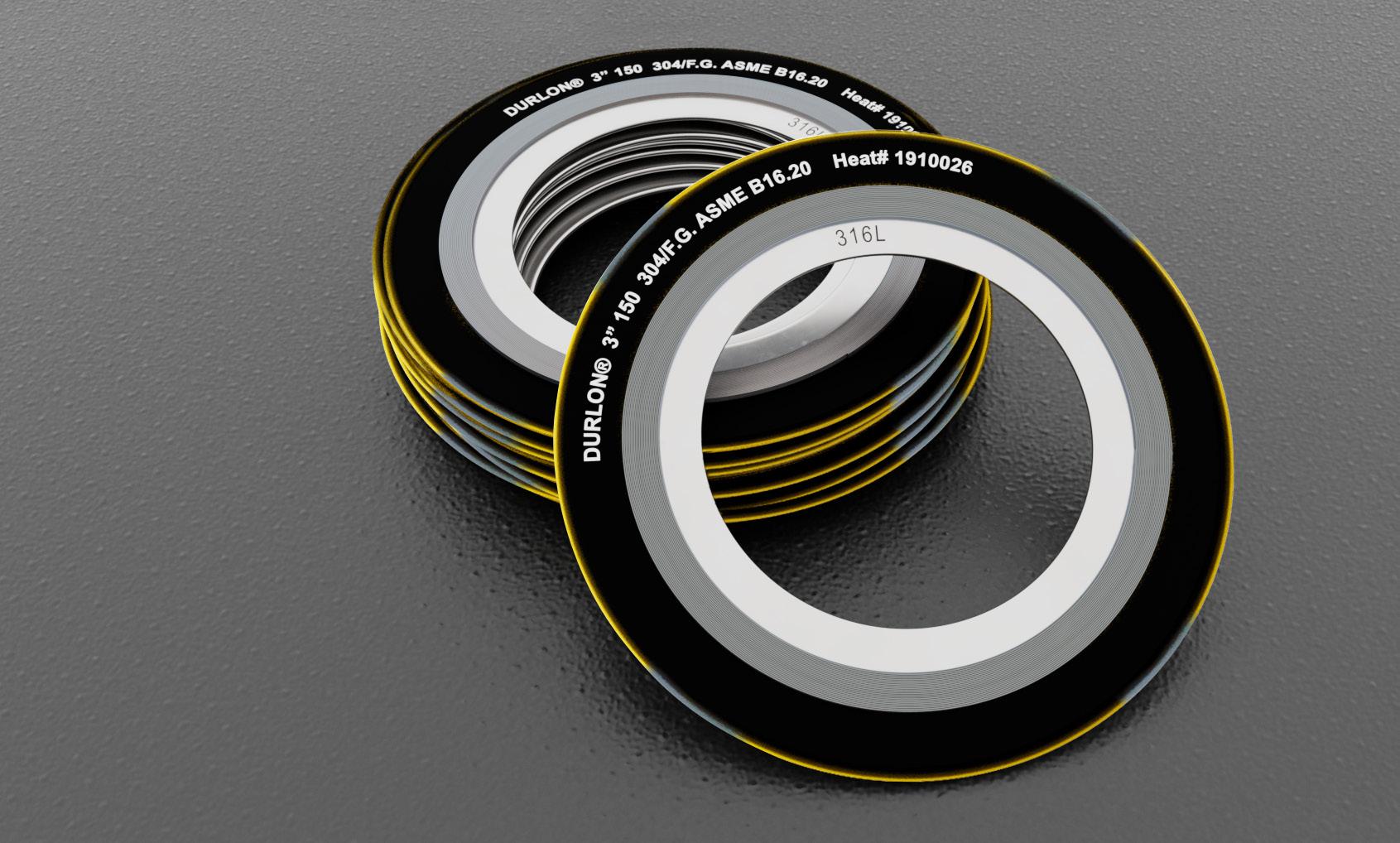
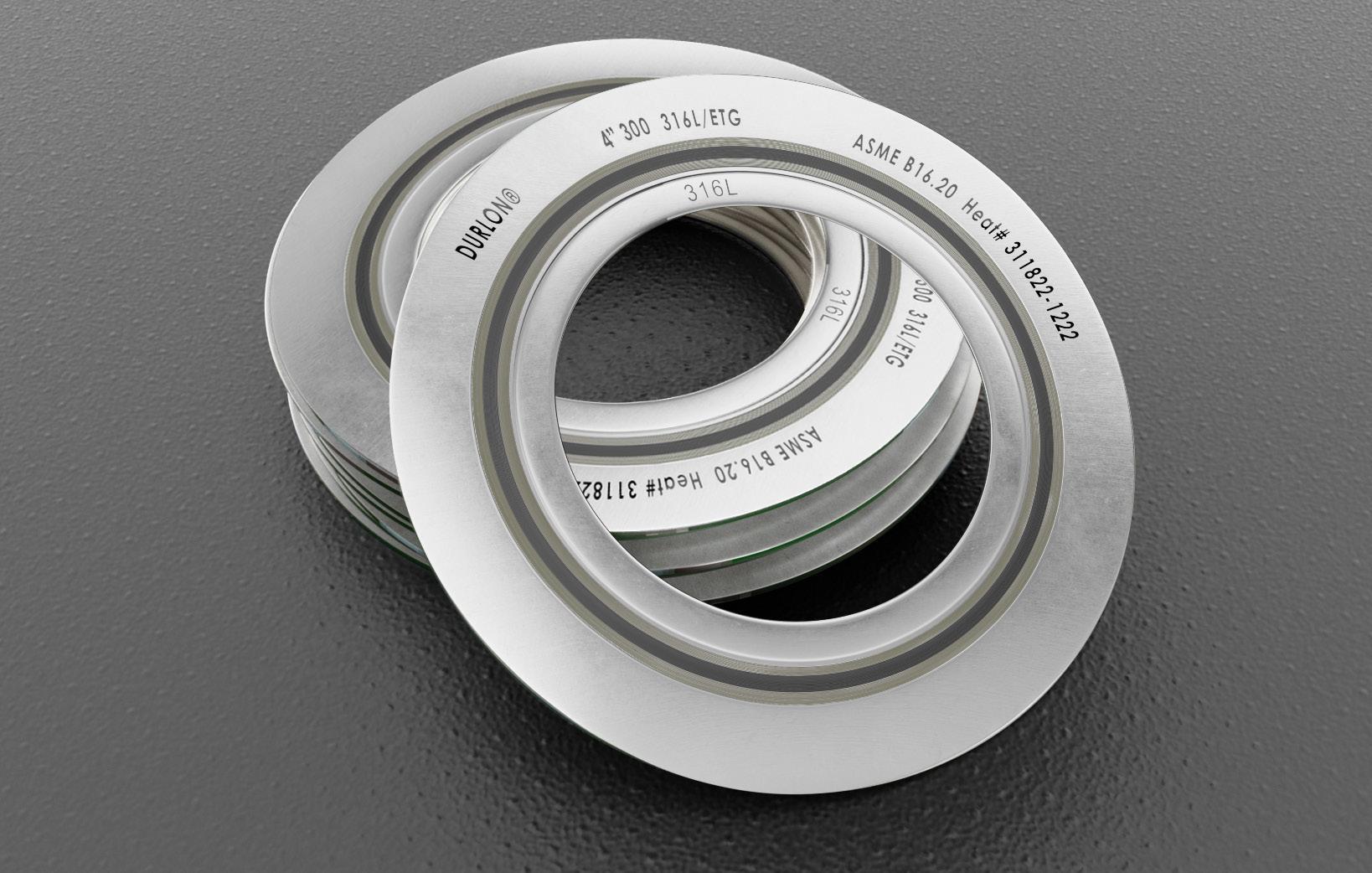
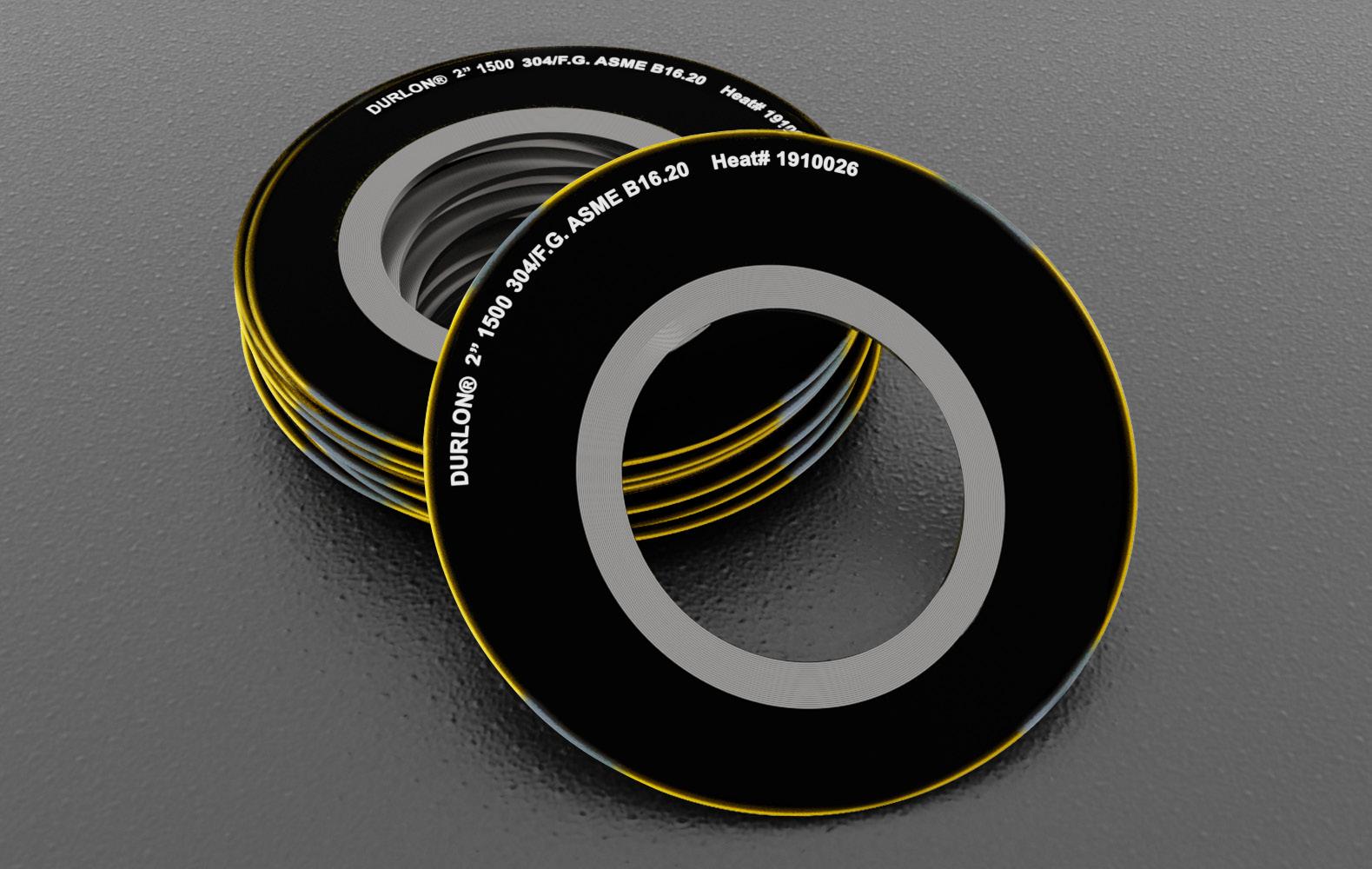
Durlon® Spiral Wound Gaskets are made with an alternating combination of a preformed engineered metal strip and a more compressible filler material which creates an excellent seal when compressed. The engineered shape of the metal strip acts as a spring under load, resulting in a very resilient seal under varying conditions. The strip metallurgy and filler material can be selected to seal a wide range of applications. All Class 150 & 300 Durlon® SWG styles have been engineered to precise manufacturing tolerances and utilize optimal winding density that allow for lower stress (bolt load) sealing compared to conventional spiral wound gaskets thus eliminating the need to stock both standard and low stress SWG’s.
All Durlon® SWG’s are manufactured according to ASME B16.20 standards. Quality Assurance complies with API Specifications Q1 and ISO 9001 standards. Super Inhibited Graphite meets the requirements of Shell Specification MESC SPE 85/203 and meets PVRC SCR Flexible Graphite Spec for FG 600 material.
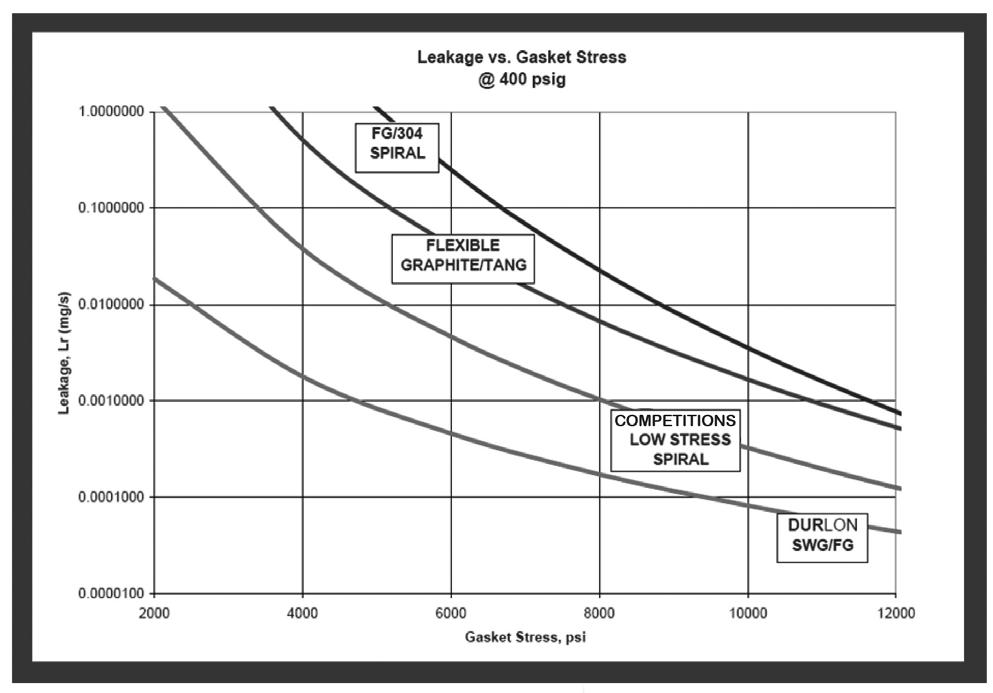
Durlon® SWG’s obtain their initial seal with very low seating stresses and provide a tighter seal than typical low stress spiral wound gaskets and other high temperature alternative gaskets. Our advanced manufacturing process allows all Durlon® SWG’s to perform better under low bolt stress applications while maintaining seal integrity under normal conditions.
INDUSTRY APPLICATIONS:
• Oil & Gas
• Mining
• Food & Beverage
• Petrochemical
• Power Generation
• Heavy Industrial
• Chemical Processing
• Pulp & Paper
Durlon® Style DR and DRI gasket centering rings (in carbon steel) are coated to inhibit atmospheric corrosion. Durlon® Spiral Wounds are packaged with the utmost care to prevent damage during shipping to the job site.
Spiral Wound Gaskets
Style: D, DR & DRI ASME B16.20 Standards
SWG
Spiral Wound Gaskets
Style:
D, DR & DRI
ASME B16.20 Standards
Style D
• Sealing element only consisting of preformed engineered metal and more compressible filler material
• Commonly used in tongue & groove or male & female flanges
• Can also be supplied with an inner ring as Style DI (Inner ring with winding and no center ring)
Style DR
• Sealing element (D) combined with a centering ring (R) which reinforces the gasket and acts as a compression stop
• Commonly used with standard Raised Face and Full Face type flanges
• Centering ring is epoxied which provides superior corrosion resistance compared to powder or liquid coating
Style DRI
• Sealing element (D) combined with a centering ring (R) and an inner ring (I) which improves radial strength and protects the sealing element from erosion and inward buckling
• Commonly used with standard Raised Face, Full Face type flanges and worn RTJ flange replacement gaskets
• Inner rings are recommended for all spiral wound gaskets but are mandatory (ASME B16 20-2007) for all PTFE filled gaskets, NPS (Nominal Pipe Size) 24” and larger Class 900. NPS 12”, larger Class 1500 and NPS 4” and larger Class 2500
Durlon® Kammprofile gaskets have a solid metal core with concentrically serrated grooves machined into the top and bottom faces. The metal core is typically stainless steel, but it can be supplied in various metallurgies as per the customer’s request.
The serrated core is covered with soft sealing material and is dependent on the service conditions of the system. Flexible graphite and expanded PTFE sealing layers are most common, but other products like HT1000® or (Extreme Temperature Gaskets) ETG’s can be used as well. While providing the Durlon® Kammprofile gasket with excellent sealing properties, the soft sealing layers also fill in minor flange imperfections and protect the flange surfaces from damage.
Durlon ® Kammprofile gaskets are the preferred choice for applications requiring improved performance at low seating stresses. The serrated peaks provide reduced contact area and when combined with the soft conformable sealing layers, the Durlon ® Kammprofile gasket provides a virtual metal-to-metal connection. They feature excellent resistance to blowout and provide superior stability for ease of handling and installation.
Durlon ® Kammprofile gaskets are offered in 4 styles in each of the 2 core designs.
INDUSTRY APPLICATIONS:
Power Generation
RoHS Reach Declaration Compliant • Oil & Gas
Pulp & Paper
Mining
Petrochemical
Certifications
Gasket Factors
Kammprofile
Serrated Flat Metal Gaskets
Grooved metal gasket with covering layers
Physical Properties
Temperature:
Min
Max (material dependent) -200°C (-328°F) 1,000°C (1,832°F)
Pressure, Max, bar (psi) 414 (6,000)
pH range, Room Temp. 0-14
CORE MATERIALS:
• Standard core material is 316 stainless steel with a nominal thickness of 0.125” (3mm)
• Other core materials and thicknesses are available to suit specific applications
• Core material is generally selected in an identical material to the piping system in order to reduce corrosion problems
FACING MATERIALS:
• Standard facing material is flexible graphite with a nominal thickness of 0.020” (0.5mm)
• Other facing materials and thicknesses are available to suit specific applications
• Meets Shell Specification MESC SPE 85/203 & PVRC SCR Flexible Graphite Spec for FG 600 material
SHAPES:
• Round, ovals (normal or irregular), manways, track shapes, diamonds, squares/rectangles, with ribs, etc.
FLANGE SURFACE FINISH:
• The ideal flange surface finish for use with Kammprofile gaskets is 125-250
CORE DESIGNS
K40P - Parallel Root Core
This core design is where the main sealing faces of the serrated metal core are parallel to each other.
K40C - Convex Root Core
This core design is where the main sealing faces of the serrated metal core are slightly convex in profile. The convex core helps compensate when flange rotation is experienced on the bolt.

AVAILABLE STYLES
K40PEF & K40CEF - Extended Core Floating, Centering Ring
Similar to the floating centering ring, this style has an extended core whereby providing additional strength and stability to the overall floating design.
K40PF & K40CF - Floating Centering Ring
A loose fitting centering ring is recommended on applications where thermal or pressure cycling can affect the integrity of the serrated metal core. It allows for expansion and contraction of the core through these cycling conditions.
K40P & K40C - No Centering Ring
This basic configuration is most often used in tongue & groove and male & female flanges.

K40PI & K40CI - Integral Centering Ring
The centering ring is used to position the gasket between flat face and raised face type flanges.
CUSTOM FABRICATED METALLIC GASKETS
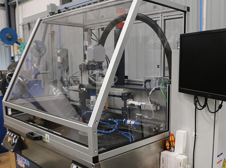
We custom manufacture Durlon® Kammprofile gaskets to customer dimensional and material requirements. These gasket styles can be manufactured with common pass bar styles, typically used in heat exchangers up to 2,642mm (104”) in diameter. Using sophisticated semi-automatic digital equipment, we can ensure that dimensional stability and assembly precision are met on every gasket produced.
Combined with full internal traceability on raw materials, we provide custom fabricated metallic gaskets that can be depended on for the entire lifespan of the installation.
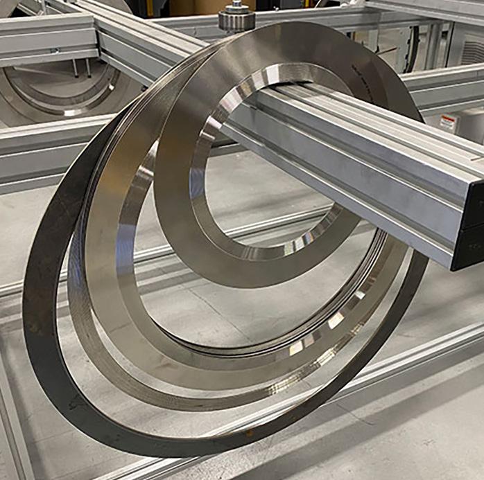
KAMMPROFILE/DURTEC GASKETS
Size range ½” – 157”
Parallel and convex cores
Floating and integral CR’s
SWG Centering Rings
SWG Inner Rings
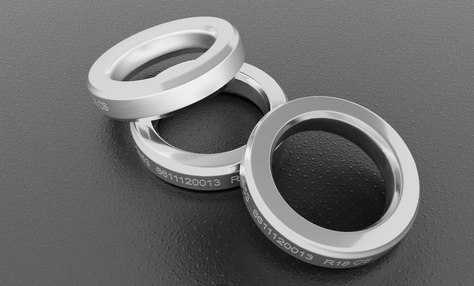
Durlon® RTJ gaskets are precision machined from solid metal and are designed for high pressure and high temperature services. They seal by creating very high unit load, metal-to-metal line contact, with special mating flanges. Metals are typically chosen so that the ring gasket is softer than the flange material in order to prevent damage to the flanges and thereby causing plastic flow of the gasket into the flange faces.
The design of the gasket or cross-section is chosen based on the existing flange configuration and designed maximum system pressure. Gasket and flange surface finishes and dimensional accuracy along with gasket hardness must be carefully controlled in order to obtain and maintain an effective seal.
INDUSTRY APPLICATIONS:
• Mining
• Power Generation
• Oil & Gas
• Petrochemical
Durlon® RTJ Characteristics
• General/Heavy Industry
• Marine
• OEM Services
• All gaskets are completely identified with low-stress permanent markings indicating style, ring number, material and applicable standards
• All gaskets fully comply with the ASME B16.20 standard and the API spec 6A (where applicable)
• All materials are fully traceable and documentation can be supplied upon request or viewed via MetalTrace® on-line: www.trianglefluid.com/ metal-trace/
• Material hardness is carefully controlled which ensures a good seal without damaging the surfaces of the flanges
• RTJ gaskets can withstand aggressive chemicals and temperatures up to 1,000°C (1,832°F) with properly selected metal
• All gaskets have a thin protective coating to eliminate oxidation effects due to atmospheric contact
Styles: R, RX, BX RTJ
Ring Type Joint Gaskets
Style R
• Available in oval and octagonal cross-sections
• Style R gaskets are interchangeable on modern octagonal flat bottom grooved flanges
• Standard sizes of Style R gaskets are manufactured in accordance with ASME B16.20 and API 6A specifications
Style R - Octagonal Style R - Oval


Style RX
• Style RX has a unique self-sealing action. The outside bevels of the ring make the initial contact, thus providing a seal against the groove’s outer surfaces. As the internal pressure increases, so does the gasket loading stress against the groove, thus improving the gaskets sealing characteristics
• Design features of the Style RX make it more resistant to shock load, test pressure shock and drilling vibration
• Style RX ring joints are completely interchangeable* with standard Style R groove designs.
*CareshouldbetakenwheninterchangingthesestylesasRXgasketsaretallerandwill addlengthtothefinishedassembly.
Style BX
• Style BX features a pitch diameter slightly larger than the groove pitch diameter. This allows for initial contact to be made on the outside of the ring, creating a pressure energized seal
• All Style BX gaskets incorporate a pressure passage to enable trapped pressure to balance itself in the joint
• Style BX ring joint gaskets can only be used with API BX flanges and are not interchangeable with Style RX
Considering the environmental climate of today, it is more important than ever to prevent leakage in your piping systems. With flanges being the most common trouble area, proper sealing is key to preventing leakage. Durlon® offers quality products and materials which can help solve most flange sealing problems from eliminating leakage to preventing corrosion, and saving the integrity of the pipeline.
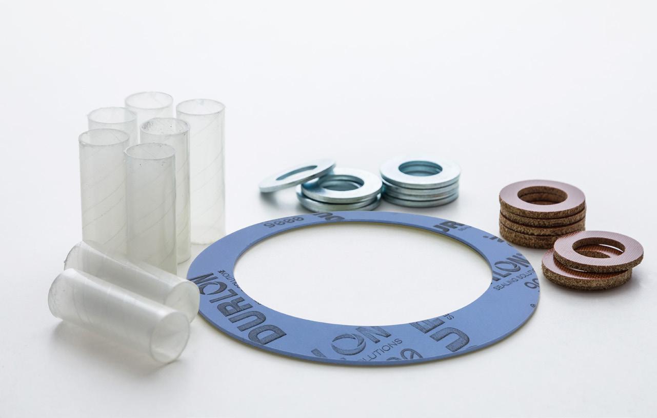
Our Durlon® iGuard™ flange Isolation & Sealing Kits are designed to be used on flanges and piping systems to create a dielectric break, which provides cathodic protection, assist in the prevention of corrosion and eventual break down of the metal, and isolate any current in the piping system from continuing down the line.
Gasket styles are available in Type F (Raised Face), Type E (Full Face) and Type D (RTJ) flanges from NPS ½” (DN15) to NPS 144” (DN 3600) or equivalent, to meet all international piping sizes. iGuard™ gaskets meet AWWA, ANSI, API, DN, JIS and all other dimensional standards.
GENERAL FEATURES
• Auto-Energizing double-ogee seal
• Low torque requirements
• Tri-directional seal movement for a tighter seal
INDUSTRY APPLICATIONS:
•Oil & Gas
•Water/Wastewater
•Food & Beverage
PACKAGING
•Marine
•Chemical Processing
•Pulp & Paper
•Petrochemical
•Mining
Each Durlon® iGuard™ Flange Isolation & Sealing Kit is packaged individually in durable corrugated boxes. Isolating sleeves and washers are packaged separately and cushioned within the box to protect them from damage during shipment. Each set is clearly tagged with flange size, pressure rating, type or isolating sleeve and whether it is a single washer or double washer set.
iGuard™
Isolation & Sealing Kits
Styles: Type F, Type E, and Type D
Type F (Ring Gasket)
The outside of the gasket fits inside of the flange bolt circle to ensure an exact positioning of the gasket.
Type E (Full Face Gasket)
This design facilitates proper alignment of the gasket during installation and prevents foreign material from shorting the flange isolation.
Type D (RTJ Gasket)
This design specifically fits into the ring groove of ring-type-joint flanges.
The Standard Kit
Consists of a gasket, isolating washers and isolating bolt/stud sleeves. The gasket carrier can be constructed of plain phenolic, neo-faced phenolic, epoxy glass (G-3, G-10 or G-11), epoxy glass (G-10) bonded to 316SS core, Durlon® 7910, 8400, 8500 or 9000.
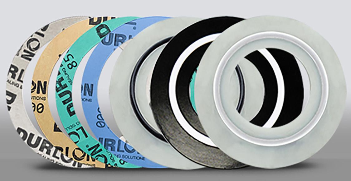
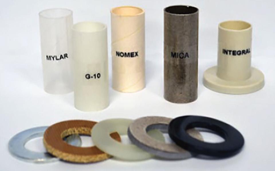
iGuard™ 7910
The iGuard™ 7910 quality commercial grade compressed sheet gasket material is manufactured from aramid/inorganic fiber material. Maximum pressure class - 300# ANSI.
iGuard™ 8400
The iGuard™ 8400 style isolation gasket is manufactured from phenolic fiber material to improve sealability in critical service chemical environments from pH 2-13 and other aggressive media to 290°C (554°F). Maximum pressure class - 300# ANSI.
iGuard™ 8500
The iGuard™ 8500 style isolation gasket is manufactured from aramid fiber material to improve sealability in steam environments to 287°C (548°F). Maximum pressure class - 300# ANSI.
iGuard™ 7910, 8400 & 8500 These kits come standard with one 3mm ( ¹⁄8”) thick genuine iGuard™ gasket, two isolating Nema grade G-10 washers, two SAE zinc plated steel backup washers, and one Nema grade G-10 sleeve tube for every bolt/stud. Maximum pressure class - 300# ANSI. These designs are ideal for ANSI Class 150 and 300 and come in sizes from NPS ½” (DN 25) to NPS 96” (DN 2400) or international equivalents in Type E (Full Face) or Type F (Raised Face) configurations.
iGuard™ 9000
The iGuard™ 9000 style isolation gasket is manufactured from 3mm (¹⁄8”) thick genuine Durlon® 9000 glass filled PTFE gasket material to improve sealability in critical service chemical environments from pH 0-14 and other aggressive media to 260°C(500°F). This design makes the iGuard™ 9000 ideal for cryogenic, petrochemical, pharmaceutical, semiconductor manufacturing, and food and beverage manufacturing applications in ANSI Class 150 and 300 or international equivalents. Sizes available: from NPS ½” (DN 25) to NPS 144” (DN 3600) in Type E (Full Face) or Type F (Raised Face) configurations. This kit comes standard with one iGuard™ 9000 gasket, two isolating PTFE washers, two SAE zinc plated steel backup washers, and one PTFE sleeve tube for every bolt/ stud. Maximum pressure class - 300# ANSI.
iGuard™ EN
The iGuard™ EN style isolation gasket is manufactured from Nema grade G-10/FR-4 glass epoxy material incorporating a Viton double-ogee sealing element. This kit comes standard with one iGuard™ EN gasket, two isolating Nema grade G-10 washers, two SAE Zinc plated backup washer, and one Nema grade G-10 sleeve tube for every bolt/stud. Maximum pressure class - 2,500# ANSI, 10,000# API.
iGuard™ CS
The iGuard™ CS style isolation gasket is manufactured from 3mm (¹⁄8”) thick Nema grade G-10 glass epoxy material bonded to a 316 stainless steel internal core with a spring energized PTFE sealing element to prevent cold flow in critical service applications under continuous reciprocation movement or internal pressure surges at elevated temperatures. This design makes the iGuard™ CS ideal for API Class 15,000 and ANSI Class 600, 900, and 2,500 flange applications. This kit comes standard with one iGuard™ CS gasket, two isolating Nema grade G-10 washers, two SAE zinc plated steel backup washers, and one Nema grade G-10 sleeve tube for every bolt/ stud. Maximum pressure class - 2,500# ANSI, 15,000# API.
iGuard™ HC
The iGuard™ HC style isolation gasket is manufactured from special high-compression 6mm (¼”) thick Nema grade G-10 glass epoxy material incorporating a spring energized PTFE sealing element to prevent cold flow under high pressures. This kit comes standard with one iGuard™ HC gasket, two isolating Nema grade G-10 washers, two SAE zinc plated steel backup washers, and one Nema grade G-10 sleeve tube for every bolt/ stud. Maximum pressure class - 2,500# ANSI, 10,000# API.
In gaskets with phenolic or glass carrier rings, the double-ogee sealing element provides a reliable concentrated unit load on the flanges, using the lowest torquing conditions possible. For other styles, a spring energized PTFE sealing element is used.
Gaskets Durlon® 7910, 8400, 8500, 9000, EN, CS, HC
Isolating Sleeves & Washers
iGuard™ Material Physical Properties
Mylar: The Isolation Sleeve is designed to fit over the bolt diameter & through the flange bolt holes inner diameter. The sleeve extends through both flanges & centers on the isolation washer thickness. Isolation Sleeves have a standard wall thickness of .03125” (.79mm), diameter & length of the isolation sleeve is determined by each application.
iGuard™ Installation Procedures

BEFORE TIGHTENING
The flange faces make contact with the sealing elements which sit slightly higher than the isolating carrier ring.
AFTER TIGHTENING
The sealing element is compressed and moves bilaterally through the gasket radius thus filling the small gaps on either side of the sealing element. This radial movement provides a tighter seal with less stress on the carrier ring as compared to rectangular sealing elements used in other gasket styles in the market. The tri-directional movement of the sealing element provides better elastic recovery over time as bolt loads relax and pressure or temperature cycles occur.
NOTE: Flanges are not included in the kit. Contact our Technical Department for more information about Installation, Bolt Torquing, the Star Patterns, and Load Values: tech@durlon.com
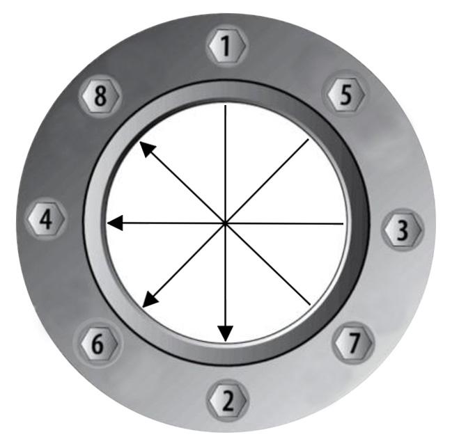
iGuard™ Recommended Application Chart
This information is a general guide for the selection of a suitable gasket material. The substances listed above are evaluated for their effect on gasket materials at ambient temperature -40°C (-40°F) to 38°C (100°F) unless stated otherwise. For unusual conditions of fluid concentration, internal pressures or temperature or applications not listed above, consult your local representative. This evaluation is based on laboratory or field tests or experience; however, no guarantee can be given as to the actual performance experienced by the end user.
Gasket Fundamentals
BLOW OUT OR INTERNAL PRESSURE
Tries to force gasket out of the flange.
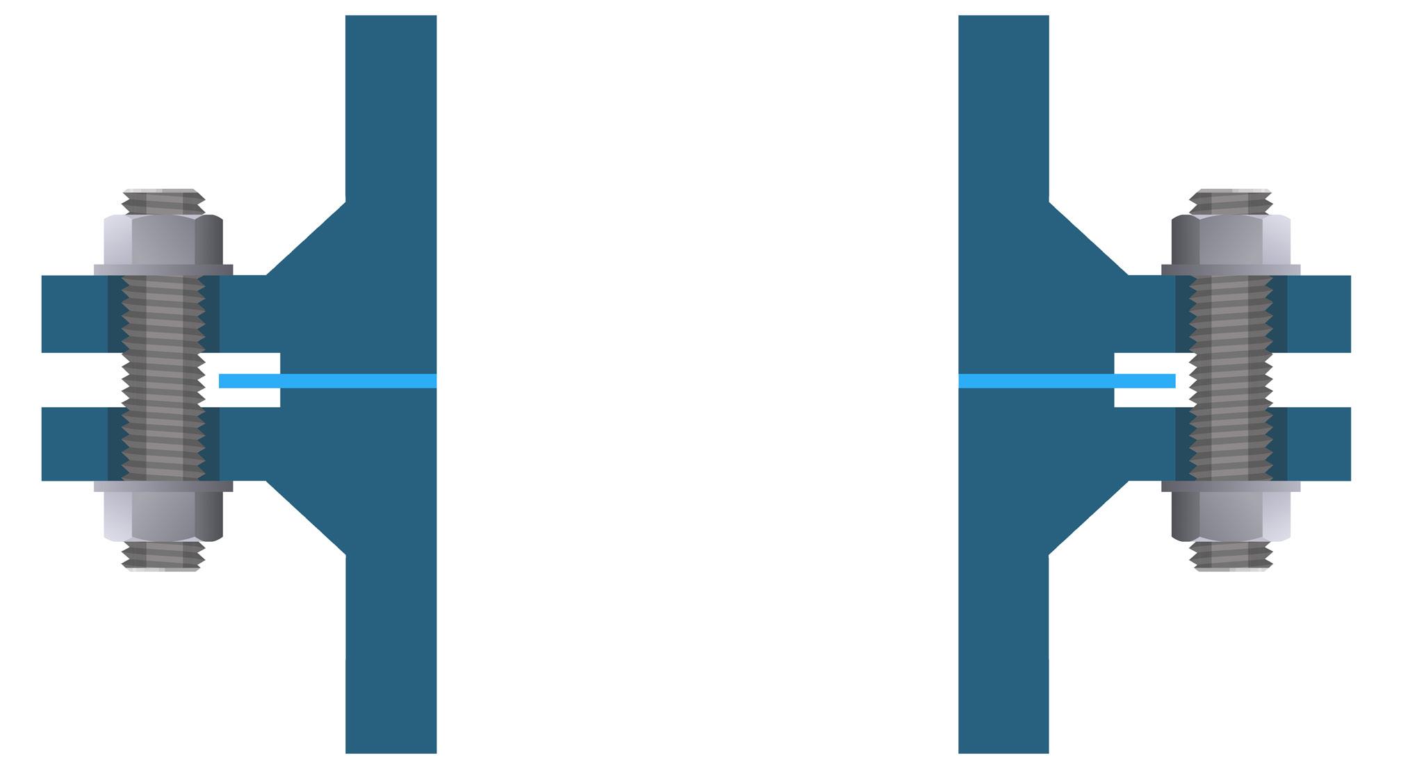
BOLT LOAD
Tries to keep everything together.
HYDROSTATIC END FORCE
Tries to push flanges apart. This stretches bolts and can lead to lower gasket compression.
FORCES THAT OCCUR IN A GASKETED JOINT
The Function of a Gasket is to create and maintain a static seal between two stationary, imperfect surfaces of a mechanical system, designed to contain a wide variety of liquids or gases. The gasket must be able to maintain this seal under all the operating conditions of the system including extremes of temperature and pressure.
The performance of the gasket is affected by a number of factors. All of these factors must be taken into consideration when selecting a gasket.
Flange Load:
All gasket materials must have sufficient flange pressure to compress the gasket enough to insure that a tight, unbroken seal occurs.
The Internal Pressure:
In service, as soon as pressure is applied to the vessel, the initial gasket compression is reduced by the internal pressure acting against the gasket (blowout pressure) and the flanges (hydrostatic end force).
Temperature:
The effects of both ambient and process temperature on the gasket material, the flanges and the bolts must be taken into account. These effects include bolt elongation, creep relaxation of the gasket material or thermal degradation. This can result in a reduction of the flange load. The higher the operating temperature, the more care needs to be taken with the gasket material selection. As the system is pressurized and heated, the joint deforms. Different coefficients of expansion between the bolts, the flanges and the pipe can result in forces which can affect the gasket. The relative stiffness of the bolted joint determines whether there is a net gain or loss in the bolt load. Generally, flexible joints lose bolt load.
Fluid:
The media being sealed, usually a liquid or a gas, with a gas being harder to seal than a liquid. The effect of temperature on many fluids causes them to become more aggressive. Therefore, a fluid that can be sealed at ambient temperature may adversely affect the gasket at a higher temperature.
FLANGE FINISHES
It is common for pipe flange finishes to vary depending on the age and condition of the piping and the gasket material considered in the initial design. Concentric-serrated finishes are most commonly used in industry, with spiral-serrated (phonographic) finishes being less prevalent. The recommended flange finish depends on the type of gasket being used. The table (below right) illustrates the Durlon® recommended flange surface finishes by gasket type.
It is recommended that metal flange faces be machined with a concentric-serrated finish of 125-500 AARH, with 250 AARH being the optimum for non-metallic gaskets. Phonographic serrations can also be used with our materials. It should be recognized, however, that their continuous leak path makes them more difficult to seal.
“Smooth” finishes are usually found on machinery or flanged joints, rather than pipe flanges. When working with a smooth finish, it is important to consider using a thinner gasket to lessen the effects of creep and cold flow. It should be noted, however, that both a thinner gasket and the smooth finish, in and of themselves, require a higher compressive force (i.e. bolt torque) to achieve the seal.
FLANGE TYPES
The majority of flange materials used in industry are metallic and come in a variety of metallurgies, depending on the nature of the application’s pressure, temperature, and media requirements. Some applications require non-metallic flange materials, such as reinforced plastic, glass-lined steel, and glass. However, these materials are less robust and “softer” gasketing materials must be used.
Raised Face to Full Face: It is not recommended to mate a Full Face flange to a Raised Face flange, especially when the Full Face flange is cast or ductile iron. Due to the potential for warping the flange, or in the worst case cracking it, the utmost care should be taken.
Even if a spacer that fits on the Raised Face flange outside the Raised Face area is used, damage to the flanges can still occur and great care should be taken.
Full Face Flanges: In a bolted joint using ANSI Full Face (or flat face) flanges it must be remembered that the same bolts used in the corresponding Raised Face joint are now being asked to seal 3 to 4 times the gasket area with Full Face flanges. It is almost impossible to create an effective seal and high strength bolts should be considered.
ANSI Class 150 Full Face bolted joints are poor design and should only be used for non-critical fluids.
ANTI-SEIZE COMPOUNDS
The use of metal-based anti-seize compounds on the gasket or flange surface is not recommended due to the following issues: under heat and pressure, the metals in the compound can adhere to the flange surface, causing distortion of the flange and/or fill in the serrations. After a period of time, when this condition has been allowed to progress, no amount of additional torque will allow the gasket to seal. Applying anti-seize to the gasket lubricates the sealing surface. This isn’t a problem until gasket compression is lost for some reason. The lubricated gasket can either be extruded, attacked chemically, or forced out of the flange by the internal pressure. Here the friction created by the flange serrations play a role.
For these reasons the use of anti-seize is not recommended. The important thing is keeping the flange serrations intact, by making sure they are thoroughly cleaned each time a gasket is changed to maintain it’s integrity, to get good compression on the gasket, and a minimum bolt stress of at least 40% of bolt yield.
BOLTING
Bolted flange connections are only as good as the fastener system being used and unfortunately the fastener system is often overlooked within the design. The majority of fastener systems being used in the industrial world are threaded. The fastener system consists of at least the bolt/stud and the nut, but it is recommended to also include washers.
The application and distribution of torque can be improved through the use of washers under the head of the bolt and between the flange and nut. Washers effectively reduce the friction between the turning surfaces of the nut and bolt head to the flange, thus translating into a more accurate load being applied to the gasket. For standard applications it is recommended to use throughhardened washers, in order to prevent washer galling.
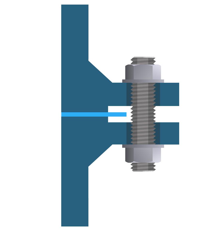
FLANGES
• Human safety
• Process safety
• Environmental concerns
• Life of service in the flange
• Maintenance costs
• Inventory costs
Other considerations when selecting a gasket are:
• Chemical compatibility with the process fluid
• The pressure-temperature (PxT Factor) relationship of the gasket to the service conditions
• Physical and mechanical properties of the gasket material
• Other considerations such as fire safety, and gasket design factors
MINIMIZING TORQUE LOSS
Proper gasket selection and installation should be based on minimizing torque loss. Torque loss can be caused by the tendency of the gasket to relax or remold after it has been compressed and/or by elongation of the bolts. This loss can be minimized several ways:
1. Use of a thinner gasket: The surface of the gasket is actually the sealing surface. The internal portion of the gasket is used primarily to ensure that the imperfections in the sealing surface are filled. Since it is this internal portion that is primarily affected by creep relaxation, the thinner the gasket, the more effective the seal. However, if the surface to be sealed is pitted, marred or somewhat distorted, it may not be feasible to switch to a thinner gasket.
2. Use of a denser gasket: In general, the denser the gasket material, the less creep relaxation will occur. With materials of similar composition, greater density will require greater seating stresses to seal. Therefore, some lighter flanges may not be strong enough to use with a denser material.
Bolting should be of sufficient strength to achieve proper compression of the gasket, to not only seal the joint, but to also maintain the seal without exceeding the yield strength of the bolts being used. The torque values in Durlon torque tables are based on using ASTM A193 Grade B7 studs and 2H heavy hex nuts lubricated with never seize.
Refer to the “Bolt Tightening Worksheet” (pg. 56) for more information on installation procedures.
GASKET SELECTION
With the emphasis on fugitive emissions gaining more and more prominence, selecting the proper gasket involves many considerations.
3. Use of a conical washer: The elastic effect of a conical washer helps to compensate for some of the loss in gasket resilience. The washer also lengthens the bolt to a slight degree, lessening the effect of bolt elongation.
4. Greater bolt load: The use of stronger bolts or more bolts can also help in the reduction of torque loss. Care should be taken to ensure that the maximum loads on the bolts are not exceeded.
CHEMICAL COMPATIBILITY
Chemical resistance of the gasket material is important because without it, the other properties of the gasket are irrelevant. It is also important to keep in mind the effect temperature has on chemical resistance.
The chemical resistance charts (pg. 64-71) can be a helpful guide. This information is available, but it must be remembered that most chemicals become more reactive at higher temperatures. This must always be considered when selecting the gasket.
In certain cases, it has been recommended to consider field testing within a controlled environment.
PRESSURE-TEMPERATURE (PXT FACTOR)
In all piping systems the flanges, valves, and the piping itself have a pressure – temperature relationship. This PxT factor is the result of multiplying the operating pressure times the operating temperature to arrive at a numerical value. This value is not constant and is different at each temperature and pressure combination. (Shown below is an example of the PxT factors for carbon steel piping per ANSI B16.34 and saturated steam)
PHYSICAL AND MECHANICAL PROPERTIES
ASTM F104, the Standard Classification System for Non-metallic Gasket Materials includes a line call-out encompassing ASTM test methods for evaluating the physical and mechanical properties of non-metallic gasket materials.
Some of these ASTM tests are:
F 36 – Compressibility and Recovery
F 2378 – Sealability
F 38 – Creep relaxation
F 146 – Fluid Resistance
F1574 – Compressive Strength
In addition to ASTM tests, testing to BSI (British Standards), DIN (German Institute for Standardization) and FSA (Fluid Sealing Association) standards can be considered. These tests include:
ASTM – F2837 – Hot Compression
DIN – 3535 – Gas Permeability
FSA – NMG-204 – High Pressure Saturated Steam Test
OTHER CONSIDERATIONS
Gasket design factors. The m and Y values established by ASME and the newer design factors being developed by the PVRC for fugitive emissions, are additional considerations. The m and Y values do not take fugitive emissions into account whereas the newer tightness parameters (Tp) do.
These gasket factors recognize that all joints leak to some extent. Therefore, an acceptable level of leakage is defined. A leak rate of ½480 lb/hr per inch of OD (0.002 mg/sec. mm) has been defined as a “standard” acceptable leak rate and is known as T2.
Tp classes and their associated leak rates are as follows: T1 – Economy –¹⁄25 lb/hr per inch of OD (0.2 mg/sec. mm)
T2 – Standard – ¹⁄2,480 lb/hr per inch of OD (0.002 mg/sec. mm)
T3 – Tight – ¹⁄248,000 lb/hr per inch of OD (0.00002
mm)
Gasket Installation

CAUSES OF GASKET FAILURE
• Uneven loading of flanges holding gasket in place
• Gasket load too low
• Bolt strength too low
• Torque loss
• Bolt relaxation/strength (approximately 10% torque lost in first 24 hours)
• Gasket creep
Reducing Gasket Failures
• Vibration in the system
• Thermal cycling
• Water hammer
• Elastic interaction during bolt tightening
• Improper gasket installation practice
• Use proper gasket installation practices
• Lubricate bolts, washers and nut facings
• Bring the flanges together slowly and parallel (multiple passes with increasing torque, each pass following proper tightening sequence).
• Use a ¹⁄16” thick gasket up to 8” flanges and ¹⁄8” for 10” and above. (¹⁄16” has less gasket creep)
• Be sure there is adequate gasket stress
• Periodic re-torquing
• Use the correct tightening pattern/method for the job: Order of efficiency (least to greatest)
1) Torque wrench
2) Hydraulic torque wrench
3) Hydraulic stud tension
• Installation procedures on the bolt tightening worksheet (pg. 56)
• Torque Values (pg. 60-63)
JOINT DISASSEMBLY WARNING
Prior to any joint disassembly, it is essential that plant procedures (lock-out and tag-out procedures) have been followed to depressurize and de-energize the system, including the removal of liquid head from the system, to ensure that the BFJA (Bolt Flange Joint Assembly) may be safely opened.
After reaffirming that all pressure on the joint has been released and the joint has been separated, proceed with bolt loosening and nut removal. Good general practice is to loosen the side of the joint away from yourself first to ensure in case of an accidental release that it is directed away from yourself. Disassembly of a BFJA should be conducted in a similar fashion as the initial assembly. Bolts should be loosened in increments and also in a crisscrossed pattern to ensure an even unload. The first loosening should be done at approximately 50% of the original recommended torque. Once joint separation is achieved, proceed with the balance of the bolt loosening and nut removal. An aid such as a hydraulic or manual flange spreader may be used if necessary to separate the joint.
Torque loss is inherent in any bolted joint. The combined effects of bolt relaxation, gasket creep, vibration in the system, thermal expansion, and elastic interaction during bolt tightening, contribute to torque loss. When torque loss reaches an extreme, the internal pressure exceeds the compressive force holding the gasket in place and a leak or blowout occurs.
A key to reducing these effects is proper gasket installation. Reduced maintenance costs and increased safety can be obtained by bringing the flanges together slowly and parallel when installing a new gasket, taking a minimum of four bolt tightening passes, and following the correct bolt tightening sequence/pattern.
Even when installation is ideal, the bolt stress is uniformly applied to each bolt, and the gasket is properly compressed, problems can still arise.
Inherently with time, loosening will occur due to gasket factors already mentioned. If other factors such as cycling, thermal upsets or vibration are present, periodic re-torquing might be necessary.
OVER-TIGHTENING - FLANGE ROTATION
The illustration below represents an over-tightening issue that can be observed on certain Class 150 flanges due to their lightweight nature. In the industry, the term “flange rotation” is used to describe this phenomenon, wherein the outer edges of the flange are “rotated” towards each other.
• Reduces the gasket contact area
• Crushes the gasket toward OD
• Allows fluid to penetrate gasket ID leading to deterioration of gasket
• Damages the flanges
• Result: leakage
In the case of Class 150 flanges, this occurrence arises due to their lightweight nature and insufficient thickness when subjected to high stress. Besides the potential damage to the flanges themselves, the over-tightening can result in gasket damage and potential leakage.
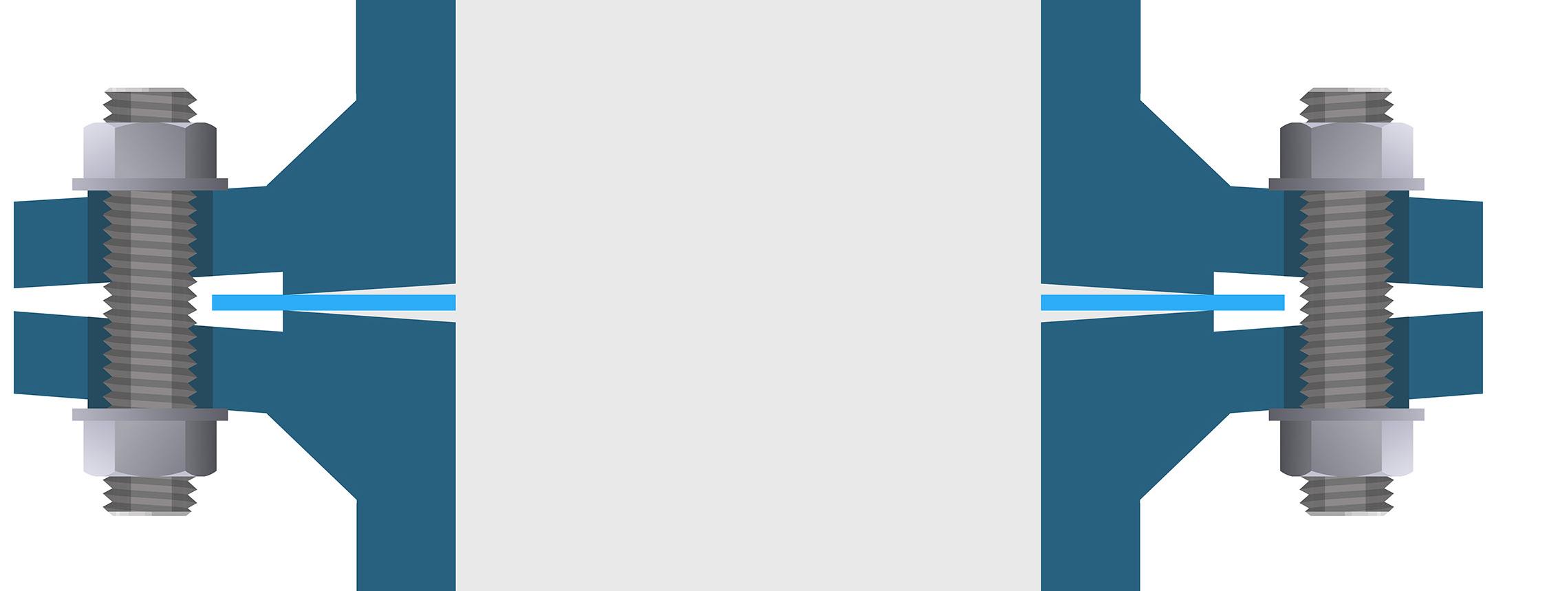
EFFECTS OF UNDER-TIGHTENING
The opposite of overloading is under-tightening, wherein an insufficient load is applied, resulting in the penetration of fluid and degradation of the gasket. It should be noted that all gaskets possess porosity and necessitate an adequate load to achieve a proper seal.
• Fluid is allowed to penetrate the gasket ID, leading to the deterioration of the gasket.
• Under-loading can lead to gasket blow-out or leakage.
• The unloading caused by temperature or pressure cycling can have an equivalent effect.
Gasket Installation Best Practices
The proper procedure for gasket installation involves meticulous attention to detail and adherence to best practices. Below is a step-by-step guide for gasket installation:
Make sure system is at ambient temperature and depressurize
Visually examine and clean flanges, bolts nuts and washers. Replace defective components if necessary.
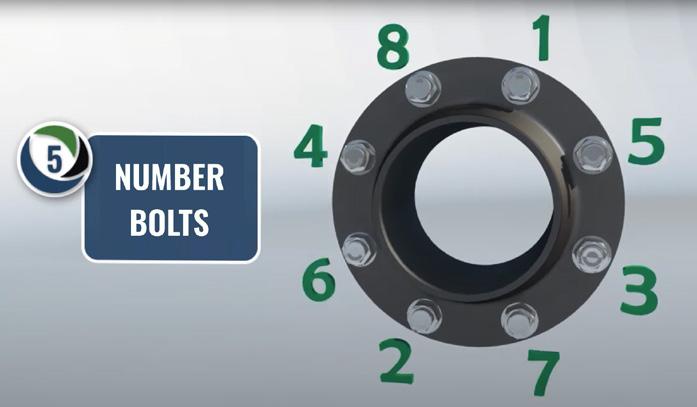
Lubricate bolt threads, nut threads & facing, and washers.
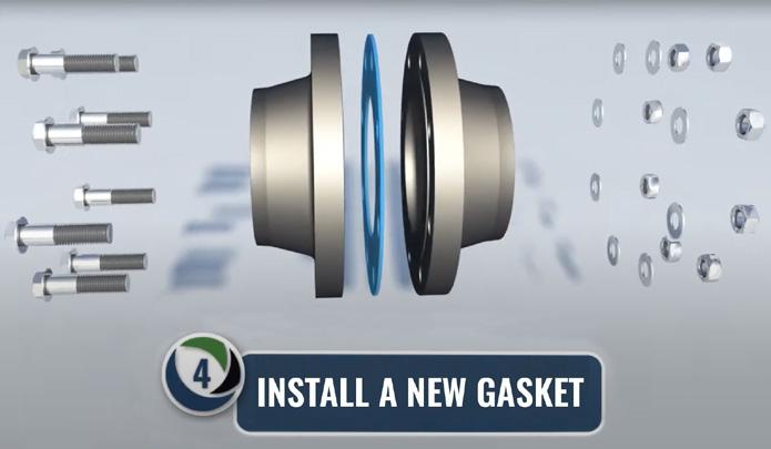
Install a new gasket. Do not reuse old gaskets or multiple gaskets.
Number bolts in a cross-pattern sequence according to this diagram. Pre-tightening; Hand tighten all nuts and if possible snug nuts with a hand wrench.
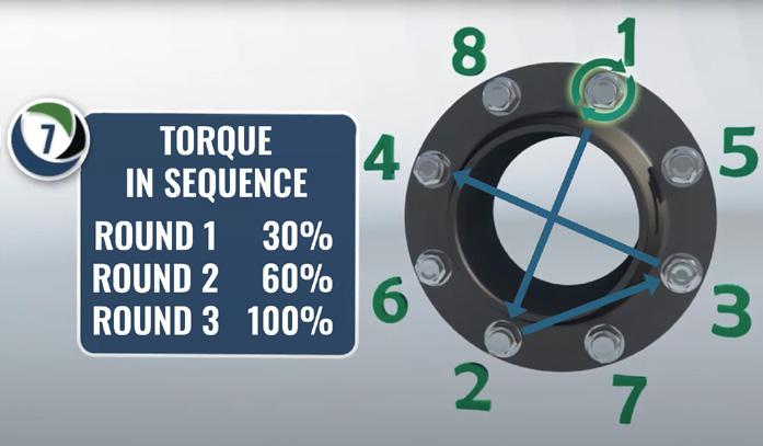
Round 1; 30% of target torque.
Round 2; 60% of target torque.
Round 3; 100% of target torque.

Use a rotational clockwise tightening sequence starting with bolt 1 for one complete round and continue until no further nut rotation occurs at 100% of the target torque value for any nut.
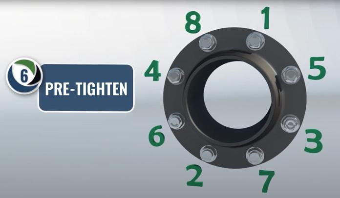
Use the appropriate cross pattern tightening sequence.

Check gap between each of these rounds, measured at every other bolt. If the gap is not reasonably uniform, make the appropriate adjustments by selective bolt tightening before proceeding.
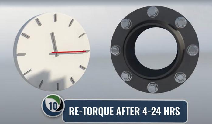
Final-round is to re-torque after 4-24 hours at ambient temperature if possible. A large percentage of short-term preload loss occurs within 24 hours after initial tightening. Repeat rotational round to recover this loss. This re-torquing round covers this loss and is especially important for PTFE gaskets.
Note: If unsure about flange finish, defects, alignment or alternative tightening procedure, please refer to ASME PCC-1 Guideline for pressure boundary bolted flange joint assembly. For other specific applications or general procedures please contact the Durlon technical department at tech@durlon.com
Durlon® Bolt Tightening Worksheet
Location/Identification:
Nominal Bolt Size:
Gasket Contact Surface Finish on Flange: Lubricant Used: (Initial each step as you progress through the list below.)
1. Be sure system is at ambient temperature and depressurized. Follow local safety rules.
2. Visually examine and clean flanges, bolts, nuts and washers. Replace components if necessary.
3. Lubricate bolts, nuts, and nut bearing surfaces. Use of hardened steel waters are recommended.
4. Install new gasket. DO NOT REUSE OLD GASKET, OR MULTIPLE GASKETS.
5. Number bolts in cross-pattern sequence according to the appropriate illustrations below.
We recommend the completion of any installation assembly worksheet with the details, including the installer signature and date for verification. You can use the Durlon worksheet for easy adoption into your QC program. 4-bolt
6. IMPORTANT! HAND TIGHTEN NUTS, then using a hand wrench, SNUG BOLTS ¹⁄8 TO ¹⁄4 turn, following the appropriate cross-pattern tightening sequence for the number of bolts below.
7. Starting at the #1 bolt, use the appropriate cross-pattern tightening sequence for Rounds 1, 2, and 3 (each sequence constitutes a "Round").
Final Torque: Ft-lbs
LUBRICATE, HAND TIGHTEN, PRE-TIGHTEN BOLTS
Round 1: Tighten to Ft-lbs - 1st torque value in torque chart (30% of final torque)
Round 2: Tighten to Ft-lbs - 2nd torque value in torque chart (60% of final torque)
Round 3: Tighten to Ft-lbs - Final torque value in torque chart (100% of final torque)
Check gap at 90º intervals around the flange between each of these rounds. Larger flanges may require checking the gap in smaller intervals. If the gap is not reasonably uniform, make the appropriate adjustments by selective bolt tightening before proceeding.
Rotational Round - 100% of Final Torque (same as Round 3). Use rotational, clockwise tightening sequence, starting with Bolt No. 1, for at least two complete rounds and continue until no further nut rotation occurs at 100% of the Final Torque value for any nut.
Retorque - Short-term bolt preload loss can occur between four to twenty-four hours after initial tightening due to bolt relaxation and/or gasket creep. Repeating the Rotational Sound recovers this loss. This is especially important for PTFE gaskets.
Joint Assembler:
For torque questions, or tightening patterns for large diameter flanges, contact tech @durlon.com **This page can be copied for use in the field**
Date:
Gasket Installation Training
Durlon® offers bolt-up and gasket training utilizing a Flange Assembly Demonstration Unit (FADU) based on ASME PCC-1 principles. This 90 minute training incorporates live feedback on the screen as the gasket is simultaneously bolted into place. Participants observe gasket deflection, bolt stress and interaction between bolts (crosstalk), and learn the value of following PCC-1 guidelines and get the opportunity to put their experience to the test.
Gasket Rig is Completely Portable
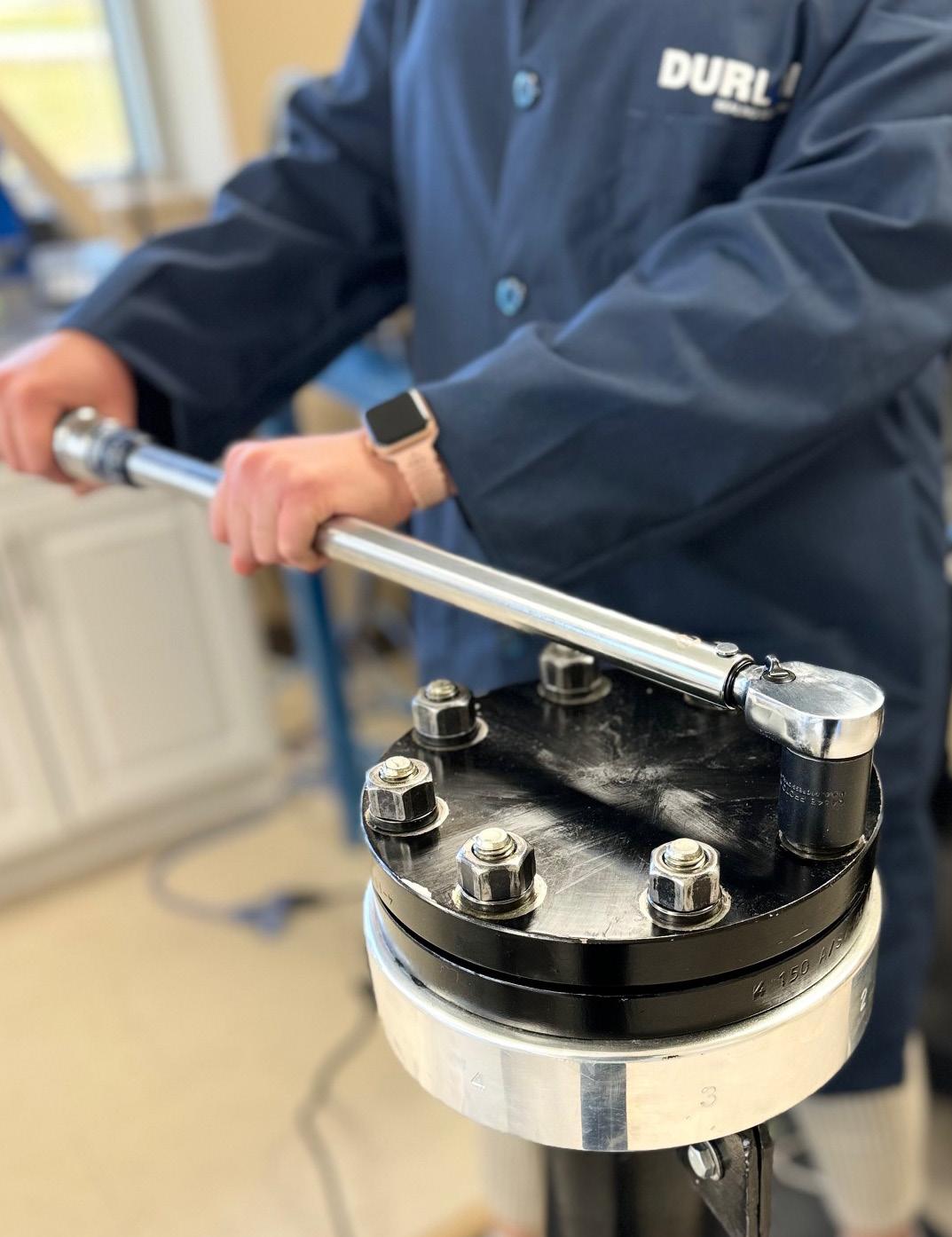
CALL NOW to arrange set-up at your location. We can conveniently set at your location. From beginner to advanced training options. Let us custom fit your needs.*
Who Should Attend Training Benefits
• Pipe fitters
• Maintenance Personnel
• Gasket Fabricators
• Gasket Distributors
• Contractors
• Engineers
• Planners
• Learn about bolted flange connections
• Increase gasket life
• Reduce maintenance costs
• Become proactive to fugitive emissions and the environment
• Increase plant pipeline safety and reliability
Agenda
• Scattered Bolt Load
• Bolt/Stud Tensile/Yield Strength
• Proper Lubrication
• Legacy/Cross Pattern Bolt-Up
• Use of Washers
• Body Positioning
• Torque/Box Wrenches
• Proper Arm Movement
Gasket Factors
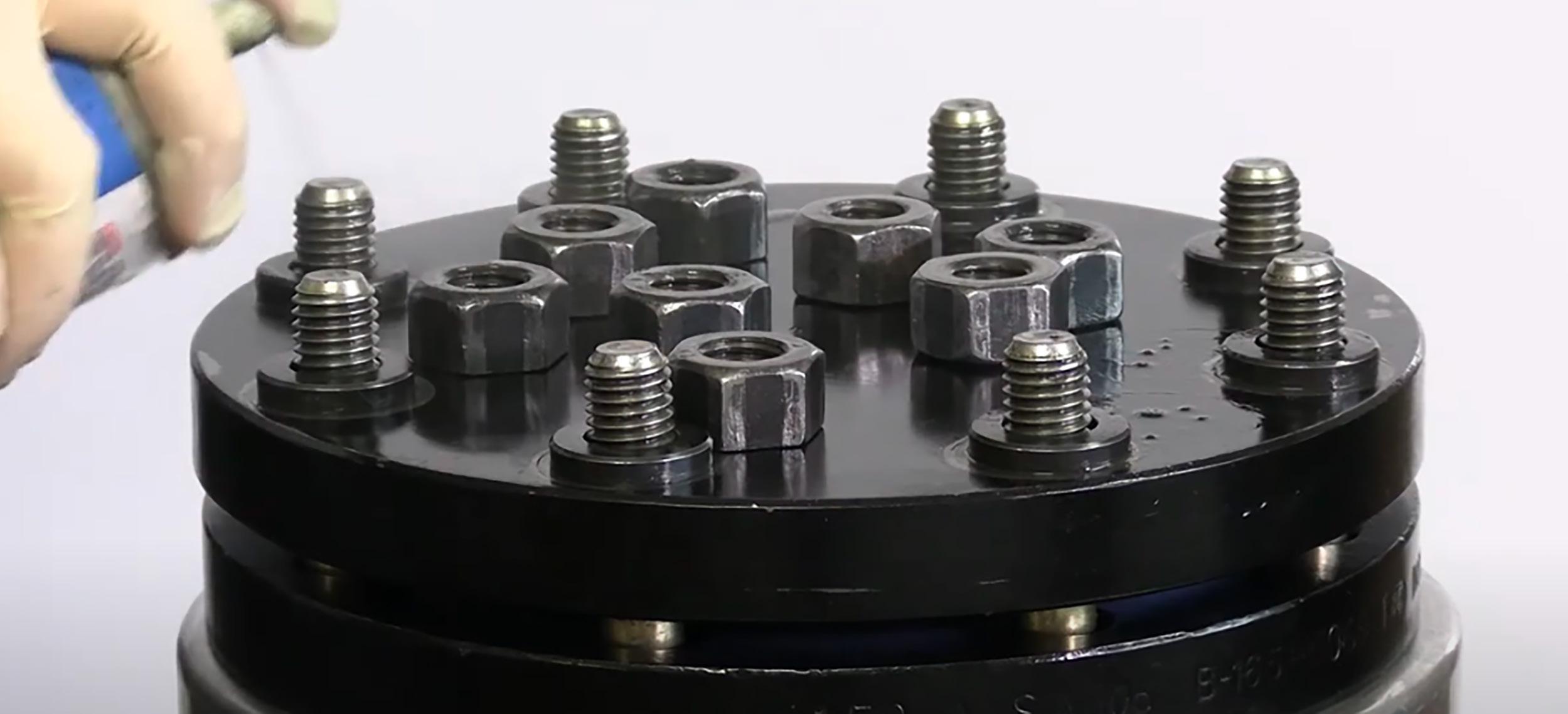
Gasket factors are very important to understand but unfortunately can be difficult to understand or are easily misinterpreted. This section contains some of the more popular versions of Gasket Factors used in determining the recommended torque for gasket installation.
EN 13555
EN 13555 is a working standard, much like ASME PVRC gasket factors, in the EU. It provides the testing procedures to allow persons to derive the gasket parameters: Qsmax, Q(minL), Qsmin(L), PQR, and EG so they can be used in design equations found in EN 1591-1 (Flanges and Their Joints - Design Rules for Gasketed Circular Flange Connections - Part 1: Calculation). For a further definition of the gasket parameters see chart (to right).
Q(minL)
Qsmin(L)
Maximum seating stress required on the gasket at a given temperature without crushing the material.
Minimum seating stress that is required in assembly at ambient temperature to seat gasket into the flange serrations and seal internal leakage, based on tightness class, L, and specified test pressure.
Minimum gasket seating stress required in service conditions after unloading gasket (at service temperature), so that the specified tightness class L, is maintained based on internal test pressure.
This factor allows for the gasket’s effect on the load applied and the relaxation of the gasket from start (final bolt-up) and after the extended life term of the material`s intended service temperature.
EG This is the unloading moduli, which is derived from the recovery of the gasket thickness between the initial compression seating stress and unloading the gasket to ¹ 3 of its initial seating stress.
When the final torque values are calculated using the previous gasket parameters, leakage can be classified into three tightness classes:
Gasket Parameters
m & Y
m and Y values are for flange design only and are not meant to be used as gasket seating stress values in actual service. “m” is known as the maintenance factor or the multiplier. The “Y” factor is the minimum stress required (psi) over the sealing area of the gasket to provide a seal at an internal pressure of 2 psig. “Y” is not considered to be the minimum seating stress for the gasket in service. These values are used in formulas in the ASME Boiler and Pressure Vessel Code, Division 1, Section VIII, Appendix 2, to give a WM1 (minimum required bolt load for operating conditions, psi) orWM2 (minimum required bolt load for gasket seating, psi) value, based on either gasket seating or the internal pressure. The flange is designed based on the greater of these two values (WM1 or WM2). This will ensure that the flange is robust enough to maintain adequate gasket seating stress, which can decline due to flange rotation with weaker flanges when bolted up and internal pressure is introduced. These values do not take fugitive emissions into account and therefore, based on leakage, newer gasket constants Gb, a, and Gs, are being developed, based on leakage to take this into account.
Alternative ASME PVRC Gasket Factors: Gb,
a and Gs
New gasket factors to replace the ASME Code m and Y are currently being developed by the Pressure Vessel Research Council (PVRC) and ASME. The current m and Y are difficult to replicate for non-asbestos gaskets and do not take joint leakage into
Filled Spiral Wound Gasket
account. The new approach to bolted joint design makes the tightness of the joint a design parameter. In a manner similar to that of the traditional ASME Code method, the design bolt load for a joint is calculated for operating and seating requirements from the new constants Gb, a, and Gs, and the required tightness class associated with the minimum tightness.
“Gb” and “a” provide the gasket seating load; similar to Y in the present Code. “Gs” is associated with the operating stress and is similar to the m value in the present Code. The proposed ASME constants Gb, a, and Gs give a design bolt load, obtained by

interpretation of leakage test data as plots of gasket stress, Sg, versus a tightness parameter, Tp. Tp is the pressure (in atmospheres) normalized to the atmospheric pressure required to cause a helium leak rate of 1 mg/sec for a 150 mm OD gasket in a joint. Since this is about the same as the OD of an NPS 4 joint, the pressure to cause a leak of 1 mg/sec of helium for that joint is its tightness. A standard test procedure, the PVRC Room Temperature Tightness Test (ROTT), has been designed to produce the constants Gb, a, and Gs. Low values for Gb, a, and Gs are desirable while a higher value of Tp means a tighter joint.
Torque Values - Durlon® Sheet Gasket Material
Fasteners: A193-B7 or B16 lubricated with a never seize type lubricant, k=0.17
Disclaimer: This is a general guide only and TFC/GRI, does not accept responsibility for negligence or misuse of this information.
General Notes:
a) Torque Values are in ft.-lbs. and assume new A193 Gr. B7 or B16 fasteners with 2H heavy hex nuts; with studs, nuts and the nut bearing surfaces lubricated with a never-seize type lubricant (k = 0.17).
b) A193 Gr. B7 & B16 fasteners have the same yield strength up to 4” diameter. There are “no” fasteners above 4” diameter in this chart.
c) All torque values are based on using a “calibrated” torque wrench.
d) All torque values in the chart above are based on using the tensile area of the fastener.
e) All torque values in chart are rounded to nearest 5 ft.-lbs.
Footnotes:
[1] Torque values are based using ASME B16.5-2020 MAWP (Maximum Allowable Working Pressure) at ambient in the gasket stress calculation. Min. Torque Values:
(2) Min. torque values are based achieving 4,800 psi gasket stress without exceeding 80,000 psi bolt stress or PCC-1 2019 FEA SA105 Max. Stud Stress Before Flange Yielding. Optimal Torque Values:
(3) Optimal torque values are based on a target of 7,000 to 12,000 psi optimum gasket stress without exceeding 80,000 psi bolt stress or PCC-1 2019 FEA SA105 Max. Stud Stress Before Flange Yielding.
Cases where torque equals ≤ 60,000 bolts stress
Cases where torque equals > 60,000 ≤ 75,000 bolts stress
Cases where torque equals > 75,000 ≤ 80,000 bolts stress
Max. Torque Values:
(4) Max. torque values are based on; max allowable 15,000 psi gasket stress; PCC-1 2019 FEA SA105 Max. Stud Stress Before Flange Yielding, or 80,000 psi bolt stress, whichever occurs 1st. Note: In some cases the max. torque values may be equal to the optimal torque values in order to optimize gasket stress levels.
[5] ½” through 1 ½” NPS & 3 ½” NPS due to “No Data”on flange yielding; Max. torque values are set to achieve max gasket stress of 15,000 or 80,000 psi bolt stress, whichever occurs 1st.
Cases where torque is based on 80,000 bolts stress.
Cases where torque is based on PCC-1 2019 FEA SA105 Max. Stud Stress Before Flange Yielding.
Cases where torque is based on max. allowable 15,000 psi gasket stress.
Torque Values - Durlon® Spiral Wound Gaskets – Class 150 & 300
Disclaimer: This is a general guide only and TFC/GRI, does not accept responsibility for negligence or misuse of this information.
General Notes:
a) Torque Values are in ft.-lbs. and assume new A193 Gr. B7 or B16 fasteners with 2H heavy hex nuts; with studs, nuts and the nut bearing surfaces lubricated with a never-seize type lubricant (k = 0.17).
b) A193 Gr. B7 & B16 fasteners have the same yield strength up to 4” diameter. There are “no” fasteners above 4” diameter in this chart.
c) All torque values are based on using a “calibrated” torque wrench.
d) All torque values in the chart above are based on the use of a inner/outer ring style (DRI) spiral wound gasket.
e) All torque values in the chart above are based on using the tensile area of the fastener.
f) All torque values in chart are rounded to nearest 5 ft.-lbs.
Footnotes:
[1] Torque values are based using ASME B16.5-2020 MAWP (Maximum Allowable Working Pressure) at ambient in the gasket stress calculation.
Min. Torque Values:
(2) Min. torque values are based achieving 12,500 psi gasket stress or at minimum above 10,000 psi gasket stress without exceeding 80,000 psi bolt stress or PCC-1 2019 FEA SA105 Max. Stud Stress Before Flange Yielding.
Cases where gasket stress is >10,000 < 12,500 psi
Optimal Torque Values:
(3) Optimal torque values are based on 25,000 psi optimum gasket stress without exceeding 80,000 psi bolt stress or 500 psi below PCC-1 2019 FEA SA105 Max. Stud Stress Before Flange Yielding.
Cases where torque equals ≤ 60,000 bolts stress
Cases where torque equals > 60,000 ≤ 75,000 bolts stress
Cases where torque equals > 75,000 ≤ 80,000 bolts stress
*Cases where gasket stress is ≥ 15,000 < 25,000 psi, **Cases where gasket stress is ≥ 12,500 < 15,000 psi, ***Cases where gasket stress is ≥ 10,000 < 12,500 psi Max. Torque Values:
(4) Max. torque values are based on; max allowable 40,000 psi gasket stress; PCC-1 2019 FEA SA105 Max. Stud Stress Before Flange Yielding, or 80,000 psi bolt stress, whichever occurs 1st. Note: In some cases the max. torque values may be equal to the optimal torque values in order to optimize gasket stress levels.
[5] ½” through 1 ½” NPS & 3 ½” NPS due to “No Data”on flange yielding; Max. torque values are set to achieve max gasket stress of 40,000 or 80,000 psi bolt stress, whichever occurs 1st.
Cases where torque is based on 80,000 bolts stress.
Cases where torque is based on PCC-1 2019 FEA SA105 Max. Stud Stress Before Flange Yielding.
Cases where torque is based on max. allowable 40,000 psi gasket stress.
Torque Values - Durlon® Spiral Wound Gaskets – Class 400 & 600
Disclaimer: This is a general guide only and TFC/GRI, does not accept responsibility for negligence or misuse of this information.
General Notes:
a) Torque Values are in ft.-lbs. and assume new A193 Gr. B7 or B16 fasteners with 2H heavy hex nuts; with studs, nuts and the nut bearing surfaces lubricated with a never-seize type lubricant (k = 0.17).
b) A193 Gr. B7 & B16 fasteners have the same yield strength up to 4” diameter. There are “no” fasteners above 4” diameter in this chart.
c) All torque values are based on using a “calibrated” torque wrench.
d) All torque values in the chart above are based on the use of a inner/outer ring style (DRI) spiral wound gasket.
e) All torque values in the chart above are based on using the tensile area of the fastener.
f) All torque values in chart are rounded to nearest 5 ft.-lbs.
Footnotes:
[1] Torque values are based using ASME B16.5-2020 MAWP (Maximum Allowable Working Pressure) at ambient in the gasket stress calculation. Min. Torque Values:
(2) Min. torque values are based achieving 12,500 psi gasket stress or at minimum above 10,000 psi gasket stress without exceeding 80,000 psi bolt stress or PCC-1 2019 FEA SA105 Max. Stud Stress Before Flange Yielding.
Optimal Torque Values:
(3) Optimal torque values are based on 25,000 psi optimum gasket stress without exceeding 80,000 psi bolt stress or 500 psi below PCC-1 2019 FEA SA105 Max. Stud Stress Before Flange Yielding.
Cases where torque equals ≤ 60,000 bolts stress
Cases where torque equals > 60,000 ≤ 75,000 bolts stress
Cases where torque equals > 75,000 ≤ 80,000 bolts stress
*Cases where gasket stress is ≥ 15,000 < 25,000 psi, **Cases where gasket stress is ≥ 12,500 < 15,000 psi, ***Cases where gasket stress is ≥ 10,000 < 12,500 psi
Max. Torque Values:
(4) Max. torque values are based on; max allowable 40,000 psi gasket stress; PCC-1 2019 FEA SA105 Max. Stud Stress Before Flange Yielding, or 80,000 psi bolt stress, whichever occurs 1st. Note: In some cases the max. torque values may be equal to the optimal torque values in order to optimize gasket stress levels.
[5] ½” through 1 ½” NPS & 3 ½” NPS due to “No Data”on flange yielding; Max. torque values are set to achieve max gasket stress of 40,000 or 80,000 psi bolt stress, whichever occurs 1st.
Cases where torque is based on 80,000 bolts stress.
Cases where torque is based on PCC-1 2019 FEA SA105 Max. Stud Stress Before Flange Yielding.
Cases where torque is based on max. allowable 40,000 psi gasket stress.
Torque Values - Durlon® Spiral Wound Gaskets – Class 900, 1500 & 2500
1
Disclaimer: This is a general guide only and TFC/GRI, does not accept responsibility for negligence or misuse of this information.
General Notes:
a) Torque Values are in ft.-lbs. and assume new A193 Gr. B7 or B16 fasteners with 2H heavy hex nuts; with studs, nuts and the nut bearing surfaces lubricated with a never-seize type lubricant (k = 0.17).
b) A193 Gr. B7 & B16 fasteners have the same yield strength up to 4” diameter. There are “no” fasteners above 4” diameter in this chart.
c) All torque values are based on using a “calibrated” torque wrench.
d) All torque values in the chart above are based on the use of a inner/outer ring style (DRI) spiral wound gasket.
e) All torque values in the chart above are based on using the tensile area of the fastener.
f) All torque values in chart are rounded to nearest 5 ft.-lbs.
Footnotes:
[1] Torque values are based using ASME B16.5-2020 MAWP (Maximum Allowable Working Pressure) at ambient in the gasket stress calculation.
Min. Torque Values:
(2) Min. torque values are based achieving 12,500 psi gasket stress or at minimum above 10,000 psi gasket stress without exceeding 80,000 psi bolt stress or PCC-1 2019
Max. Stud Stress Before Flange Yielding.
Optimal Torque Values:
(3) Optimal torque values are based on 25,000 psi optimum gasket stress without exceeding 80,000 psi bolt stress or 500 psi below PCC-1 2019 FEA SA105 Max. Stud Stress Before Flange Yielding.
Cases where torque equals ≤ 60,000 bolts stress
Cases where torque equals > 60,000 ≤ 75,000 bolts stress
Cases where torque equals > 75,000 ≤ 80,000 bolts stress
*Cases where gasket stress is ≥ 15,000 < 25,000 psi, **Cases where gasket stress is ≥ 12,500 < 15,000 psi, ***Cases where gasket stress is ≥ 10,000 < 12,500 psi Max. Torque Values:
(4) Max. torque values are based on; max allowable 40,000 psi gasket stress; PCC-1 2019 FEA SA105 Max. Stud Stress Before Flange Yielding, or 80,000 psi bolt stress, whichever occurs 1st. Note: In some cases the max. torque values may be equal to the optimal torque values in order to optimize gasket stress levels.
[5] ½” through 1 ½” NPS & 3 ½” NPS due to “No Data”on flange yielding; Max. torque values are set to achieve max gasket stress of 40,000 or 80,000 psi bolt stress, whichever occurs 1st.
Cases where torque is based on 80,000 bolts stress.
Cases where torque is based on PCC-1 2019 FEA SA105 Max. Stud Stress Before Flange Yielding.
Cases where torque is based on max. allowable 40,000 psi gasket stress.
Chemical Resistance - Non-Metallic Gaskets
Chemical Resistance - Non-Metallic Gaskets
The following information is a general guide only for the selection of a suitable gasket material as there are unlimited combinations of
Biodiesel (>B15)
Boiler Feed Water
Bromine (Liquid)
Bromine (Gas)
Butyl Alcohol (Butanol)
Amine
Chemical Resistance - Non-Metallic Gaskets
The following information is a general guide only for the selection of a suitable gasket material as there are unlimited combinations of fluid, pressure, and temperature conditions.
Chemical Resistance - Non-Metallic Gaskets
The following information is a general guide only for the selection of a suitable gasket material as there are unlimited combinations of fluid, pressure, and temperature conditions.
Fatty
Chemical Resistance - Non-Metallic Gaskets
The following information is a general guide only for the selection of a suitable gasket material as there are unlimited combinations of fluid, pressure, and temperature conditions. A = Acceptable C = Caution-Dependent on Conditions NS = Not Suitable - = No Data Available
Chemical Resistance - Non-Metallic Gaskets
The following information is a general guide only for the selection of a suitable gasket material as there are unlimited combinations of
Chemical Resistance - Non-Metallic Gaskets
Chemical Resistance - Non-Metallic Gaskets
The following information is a general guide only for the selection of a suitable gasket material as there are unlimited combinations of fluid, pressure, and temperature conditions. A = Acceptable C = Caution-Dependent on Conditions NS = Not Suitable - = No Data Available
The information provided in the Chemical Resistant Charts (pages 64-71) is a general guide for the selection of a suitable gasket material. The substances listed are evaluated for their effect on the gasket materials at ambient temperature -40°F/C to 38°C (100°F) unless stated otherwise. For unusual conditions of fluid concentrates, internal pressures or temperature consult our technical support team. This evaluation is based on experience and laboratory or field tests. No guarantee can be given as to the actual performance experienced by the end user. There are several fluids used in food which can be sealed by SBR, however due to flavor pickup, we have marked these products “Caution.” These chemical resistance charts supersede and obsolete all previously issued charts.
While significant efforts have been made to ensure the accuracy of this information, we disclaim responsibility for errors that have occurred after the printing of this manual. Specifications may undergo changes without prior notice. For the latest and most accurate information, kindly visit www.durlon.com/resources/technical-references/
Gasket Dimensions ASME B16.21 - Cut Gaskets & CFG’s
B16.5
Gasket Dimensions - Durtec® - Units in inches (millimeters)
Gasket Dimensions - Spiral Wound Gaskets - Units in inches
* Windings ID/Outer Ring OD ** Inner Ring ID Notes:
1. Inner rings (style DRI) are required for all PTFE filled gaskets; for “all other” filler materials NPS 24” Class 900 gaskets, NPS 12” - 24” Class 1500 gaskets, and NPS 4”
(see shaded areas on chart ).
2. The dimensions for Class 300, Class 400, & Class 600 gaskets in NPS ½” - 3” sizes are the same and are designated as dual Class 300/400/600 in these sizes and shall be marked accordingly.
3. The dimensions for Class 900 & 1500 gaskets in NPS ½”- 2 ½” are the same and are designated as dual Class 900/1500 in these sizes and shall be marked accordingly.
4. Where there are no sizes listed for Class 400 flanges in NPS ½ thorough NPS 3 ½ (use Class 600); Class 900 flanges in NPS ½ thorough NPS 2 ½ (use Class 1500).
5. There are no flanges in NPS 3 ½ Class 900 and Class1500; or Class 2500 flanges in NPS 3 ½ or NPS 14 and larger.
6. Inner rings (style DRI) are the default selling condition for graphite filled gaskets. If inner rings are not required, “no inner ring” (style DR) must be specified for graphite or mica-graphite filled gaskets at time of order. Adapted from ASME B16.20.
7. Adapted from B16.20.
3
Gasket Dimensions - Spiral Wound Gaskets - Units
in millimeters
* Windings ID/Outer Ring OD ** Inner Ring ID Notes:
1. Inner rings (style DRI) are required for all PTFE filled gaskets; for “all other” filler materials NPS 24” Class 900 gaskets, NPS 12” - 24” Class 1500 gaskets, and NPS 4” - 12” Class 2500 gaskets (see shaded areas on chart ).
2. The dimensions for Class 300, Class 400, & Class 600 gaskets in NPS ½” - 3” sizes are the same and are designated as dual Class 300/400/600 in these sizes and shall be marked accordingly.
3. The dimensions for Class 900 & 1500 gaskets in NPS ½”- 2 ½” are the same and are designated as dual Class 900/1500 in these sizes and shall be marked accordingly.
4. Where there are no sizes listed for Class 400 flanges in NPS ½ thorough NPS 3 ½ (use Class 600); Class 900 flanges in NPS ½ thorough NPS 2 ½ (use Class 1500).
5. There are no flanges in NPS 3 ½ Class 900 and Class1500; or Class 2500 flanges in NPS 3 ½ or NPS 14 and larger.
6. Inner rings (style DRI) are the default selling condition for graphite filled gaskets. If inner rings are not required, “no inner ring” (style DR) must be specified for graphite or mica-graphite filled gaskets at time of order. Adapted from ASME B16.20.
7. Adapted from B16.20.
Flange Size (NPS)
Gasket Dimensions - Kammprofile - Units in inches (millimeters)
Notes:
1. The dimensions for Class 300, Class 400, & Class 600 gaskets in NPS ½” - 3” sizes are the same and are designated as dual Class 300/400/600 in these sizes and shall be marked accordingly.
2. The dimensions for Class 900 & 1500 gaskets in NPS ½”- 2 ½” are the same and are designated as dual Class 900/1500 in these sizes and shall be marked accordingly.
3. Where there are no sizes listed for Class 400 flanges in NPS ½ thorough NPS 3 ½ (use Class 600); Class 900 flanges in NPS ½ thorough NPS 2 ½ (use Class 1500).
4. There are no flanges in NPS 3 ½ Class 900 and Class1500; or Class 2500 flanges in NPS 3 ½ or NPS 14 and larger.
5. Adapted from B16.20.
Custom Capabilities
Durlon® prides itself in offering high-quality fabricated sealing components with high-precision and fast turnaround capabilities. Our state-of-the-art research and development facilities are geared to meet the ever-changing demands required in today’s variety of service conditions. This is the reason why we use some of the most modern and sophisticated processes to meet your custom needs.
The following list of our custom capabilities is why we invest back into our companies to bring you the very best in sealing solution technology.
FLASH CUTTER
We use modern digital flatbed cutting machines that can cut gaskets with precision, accuracy, and less start-up time, resulting in improved quality of the finished parts. Our machines work with various styles of sheet gasket materials; single, multi-layered, and in thicknesses up to 8mm (5/16”).
With our primary CNC controlled cutting table, we can quickly, and precisely cut almost any custom shape with no minimum order requirements. Our equipment eliminates the need to have dies made, which is costly and comes with long lead times. We package all cut gaskets with lot traceability identification tags in compliance with our ISO Quality System.

PTFE WELDING
Some applications used in designs for chemical reactors, food and beverage vessels, and heat exchangers, require PTFE gaskets larger than 1,524mm (60”) in diameter. Many fabricators simply use a traditional dovetail design, joining several segments together to form the finished large gasket. Sometimes these dovetails are wrapped in additional material and may be covered in special form-in-place liquid sealants, in order to seal the leak paths created from this design. This approach may lead to leaks and can make the gasket very hard to install.
By using segments cut from our digital flatbed cutting machine, we are able to solve dovetail design problems. We can bond segments together, creating a superior performing gasket with our proprietary welding procedure, and equipment designed by our in-house mechanical engineering experts. Our finished Ring Type or Full Face gaskets can be made with cross-sections up to 229mm (9”) wide, giving our customers the reassurance that their large diameter sealing requirements will perform as expected.

LASER METAL CUTTING MACHINE
This fiber sheet laser cutter is used for cutting thin sheet metal like carbon steel, stainless steel, brass, aluminum, copper, and various other metals. With power ranges from 1000watts – 3000watts, our laser cutting machine can cut thin metal sheets quickly and accurately and up to 25/32”, and has passed the CE/FDA/ETL certification for safe and effective use.
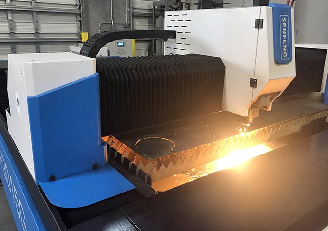
CNC LATHE CUTTING
The lathe cutting process produces an extremely precise and accurately cut, finished gasket because it follows the same stringent quality control parameters as our large sheet manufacturing process. This process is efficient and cost effective when producing high volume ring, and step ring gaskets, and highly recommended for smaller PTFE billets.
Our lathe-cut PTFE gaskets are produced using only the best quality billets of Durlon® 9000, 9000N, 9200, and 9400 – some of the most highly recommended PTFE gasket material approved for use with a number of important industrial chemicals.
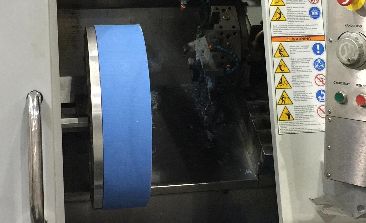
SWG WINDING MACHINE
Ensures repeatability and consistent quality
Quick turnaround on Style D, DR and DRI gaskets
Custom thicknesses available for special OEM equipment
Sizes from ½” ID to 157” OD
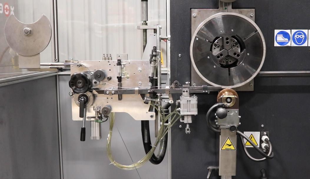
CUSTOM METALLURGY
Due to increasing demand in high performance metallurgy requests for both critical and chemical applications, we stock numerous alloys for both standard and custom gasket requirements. Our metal inventory includes: 304SS, 316L, 317SS, 321SS, 347SS, Monel 400, Duplex 2205, Super Duplex 2507, Alloy 20, Hastelloy C276, Inconel 600/750/825, Titanium, and Zirconium (Zr702).

CUSTOM FABRICATED METALLIC GASKETS
We custom manufacture spiral wound and Kammprofile gaskets to customer dimensional and material requirements. Both gasket styles can be manufactured with common pass bar styles, typically used in heat exchangers up to 2,642mm (104”) in diameter. Using sophisticated semi-automatic digital equipment, we can ensure that dimensional stability and assembly precision are met on every gasket produced. Combined with full internal traceability on raw materials, we provide custom fabricated metallic gaskets that can be depended on for the entire lifespan of the installation.

KAMMPROFILE/DURTEC GASKETS
Size range ½” – 157”
Parallel and convex cores
Floating and integral CR’s
SWG Centering Rings
SWG Inner Rings
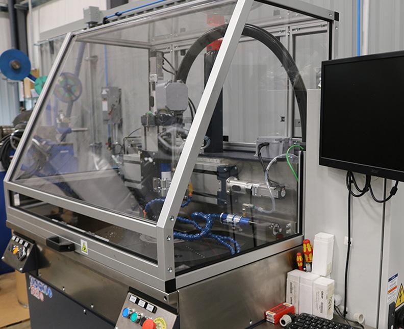
WATER JET CUTTING
This "State of the Art" water jet cutting table with high intensity pump and 5 axis cutting head, allows 3D cutting for up to 6’6” x 10’ sheets of metal, CNA, and PTFE. With this new addition to our manufacturing facility, we can cut all metal gasket components from SWG’s to Kammprofiles, with cutting speeds of 400 IPM speed range and +/0.005” accuracy. This new technology allows us to offer high precision products with quick turn-around times, on both standard and custom gaskets in metallurgies that can range from 304SS to Zirconium.
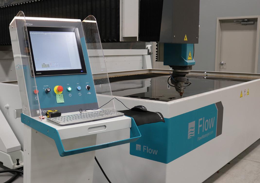
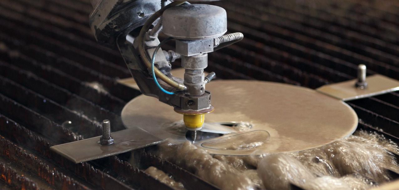
HYDRAULIC BENDER
Hydraulic bending allows us the ability to bend rings for both spiral wound components and Kammprofile gaskets utilizing the flat bar strip from either slit coils or strips cut from sheets on our water jet table. This allows us to be more cost effective when manufacturing large OD gaskets because there is no center drop from the material, which can increase the gasket’s cost. We have the ability to bend gasket OD’s from 8”-167” with ¼” through 2” cross sections.
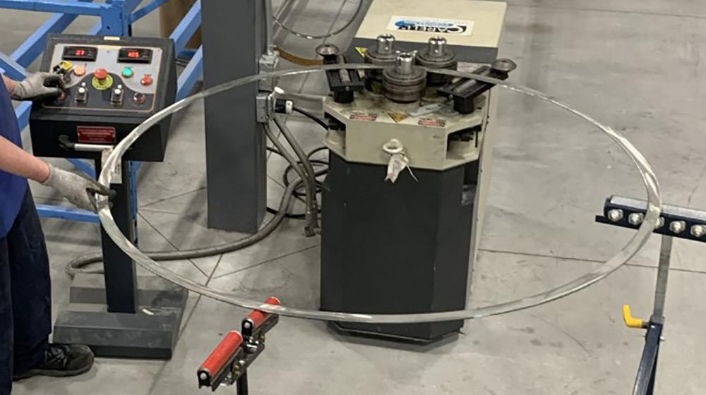
LASER MARKING
We utilize a Class 1 fiber laser to mark all of our metal gasket components for easy identification and traceability. Not only does it mark the size and class of the gasket, but the heat #, PO# and even QR Code can be added if required.

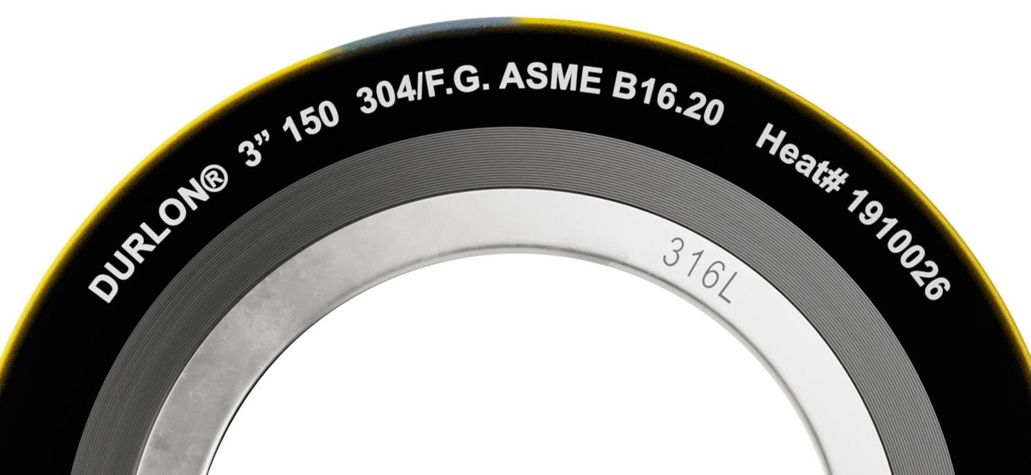
RCA® GASKETS
The Durlon® RCA® (Reduced Contact Area) sealing system combined with Durlon® PTFE styles, can replace standard Full Face gaskets in FRP, PVC, and other non-metallic and metallic pipe flanges, where a low stress gasket is required. The RCA® configuration reduces the total gasket contact area, resulting in a lower seating stress at a given torque level, while preventing flange rotation. The RCA® configuration can be cut from standard sheets resulting in a cost savings, versus other low stress gaskets. Available Materials: Durlon® PTFE and Compressed Non-Asbestos styles.
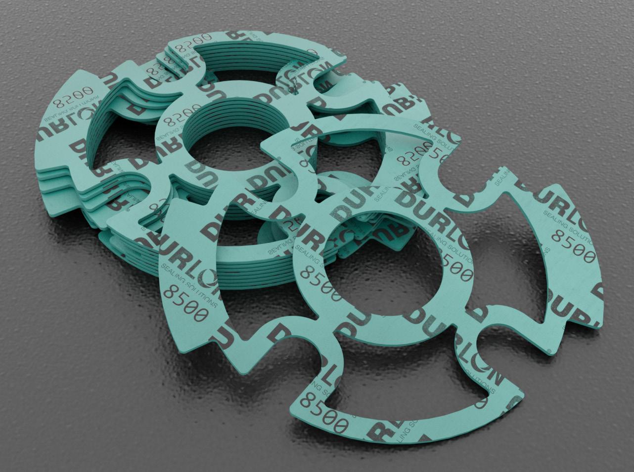
MODULA AUTOMATIC VERTICAL STORAGE SYSTEM
This vertical storage solution is perfect for making the most of the height of our warehouse while saving floor space; are the ideal answer for an orderly, clean, and safe work environment. At Durlon, we are always looking at ways to re-invest in our facilities, and with the acquisition of 3 Modula systems at TFC and 1 at GRI, we can recover space, save time, reduce risks and improve the accuracy of our inventory management.
These units are composed of a sturdy steel structure that houses and supports the trays, with a motorized central elevator to move them from the support shelves to the operator bays for picking and storing gaskets.

SKIVING
Durlon® PTFE skived materials give gasket cutters great value due to higher yields and optimal performance. With our proprietary manufacturing method, we are able to hold a tight thickness tolerance across a 60” sheet. Additionally, we are able to offer sheet lengths in 60” increments. Longer sheet lengths provide better yields and many gasket cutters prefer to take full rolls of material for continuous feed cutting operations.
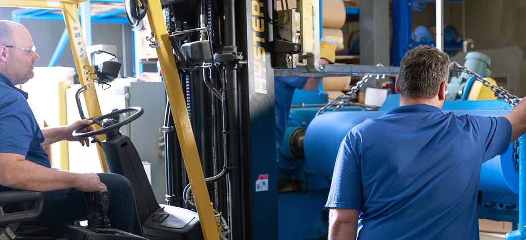

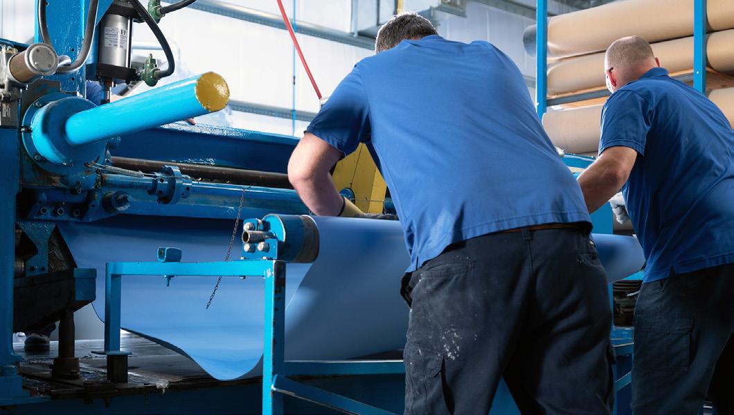

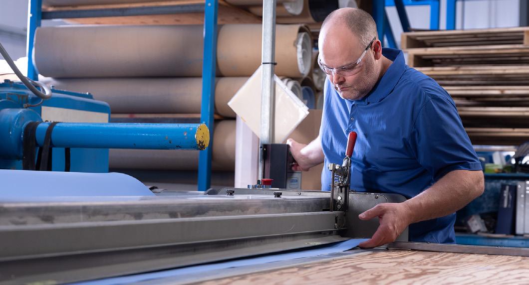
BRANDING
Durlon® manufactured gasket sheets are branded with the production date* (month/year) and a batch number for full traceability to the raw materials used during processing.
*Applies to Compressed Non-Asbestos gasket sheets.
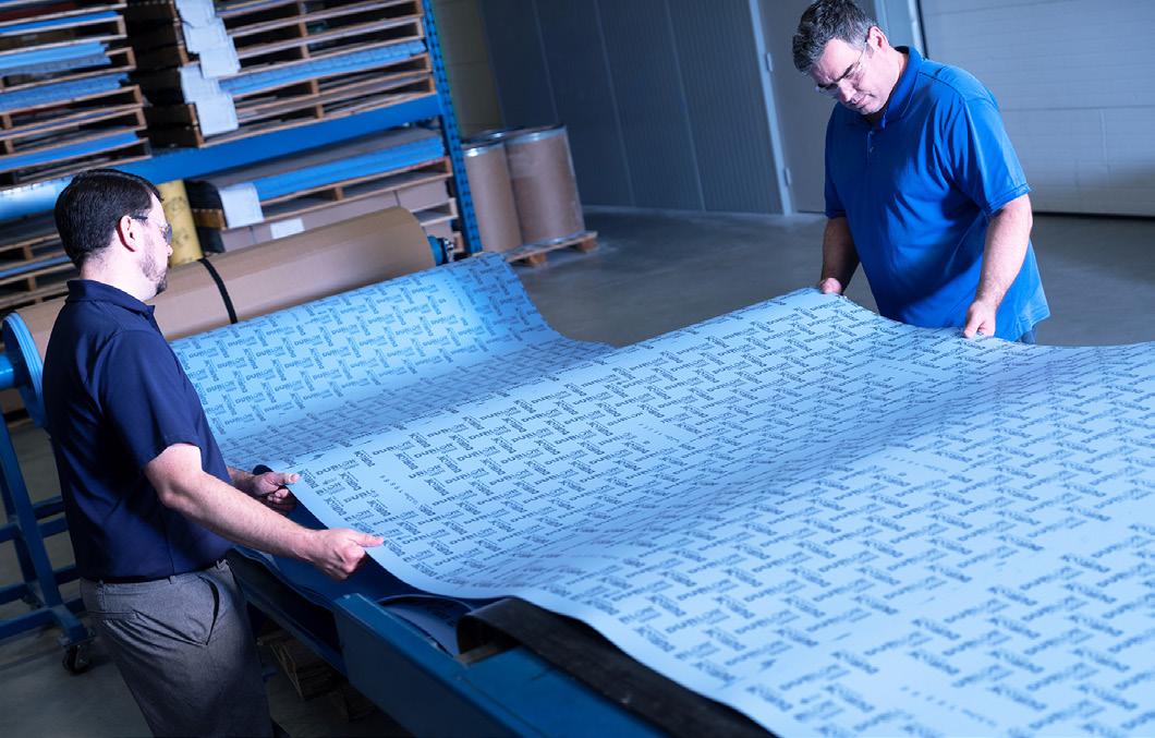
AUTOCAD AND DESIGN
Our AutoDesk CAD design programs (AutoCAD and Inventor Professional) allow us to create both 2D and 3D drawings of gaskets and components.

LAB CAPABILITIES
All our gasket testing is done in-house on both qualified raw material and finished gasket products. We perform various ASTM tests for gasket properties; tensile, creep, leakage, and compressibility/ recovery. We have ovens for conditioning samples and performing our own oxidization testing on graphite and other high-temperature materials. Our Amtec machine allows us to perform all standard required gasket performance testing, along with other tests that require high levels of accuracy. We test gasket factors (EN 13555), ultra-low emissions leakage testing with the use of a helium mass spectrometer, and competitor material testing. We have PMI (Positive Material Identification), and hardness testing equipment for verification of all our metallurgy that is brought into the plant, and before being used for production.

METAL TRACING
Mill Test Reports ( MTRs) provide traceability and assurance to the end user by stating the quality of the material, and the process used in its production. With MetalTrace® software, we create and manage MTRs which is easily available to our distribution channel via the MetalTrace® portal.
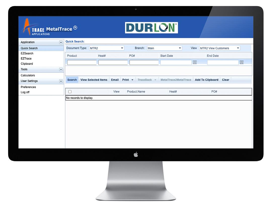
PACKAGING AND SHIPPING
At Durlon®, we take pride in our careful handling of gasket material when it comes to ensuring that they arrive at their destination in good condition. We do this by using packaging materials that is sturdy and durable, and wrap the gaskets in protective material to prevent them from rubbing against each other during transport. We use reliable and reputable shipping carriers that provide tracking numbers to monitor progress and ensure arrival at the destination on time.