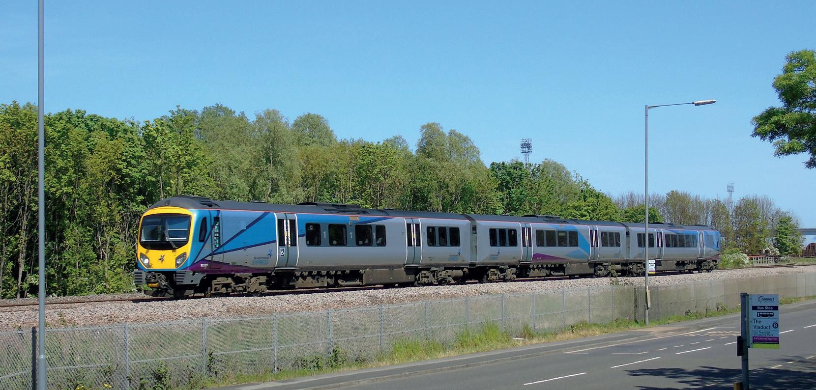
Class 185
185 Defibrillators
As part of a business plan commitment, we have started a project to install defibrillators on all Class 185’s by the end of the financial year. We are also looking at options to tidy up the emergency equipment cupboard which includes brackets to hold items. Designs for the changes are being finalised by Siemens for review and approval.
Engine Midlife programme
The first engine midlife has been completed at Ardwick depot. The work is required due to a previous engineering change detailing the extension of the Class 185 engine overhaul from 18,000 to 24,000 operating hours and the work completed in the midlife will ensure that Siemens can maintain reliable engine performance before the overhaul. This will be completed by proactively inspecting and renewing components that have been known to reduce reliability on the fleet over the last 12 months, which has been monitored using recent data - such as work order history and material consumption.
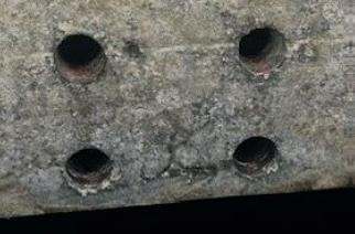
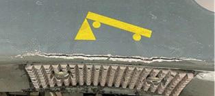
185101 Sole Bar repair
Whilst on depot Siemens found that the side skirt on 185101 had suffered impact damage and as a result, thread damage to the sole bar which the skirt mounts to. After an investigation Siemens fixed the drill larger holes in the solebar and tap new, larger threads of M22 for the inserts. The increase in the thread size increases the pull-out strength and therefore reduces the likelihood of the damage re-occurring. This work was approved via engineering change and completed in early May. 185101 has been out in service since with no issues.
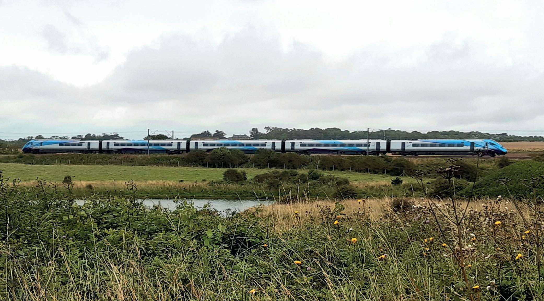
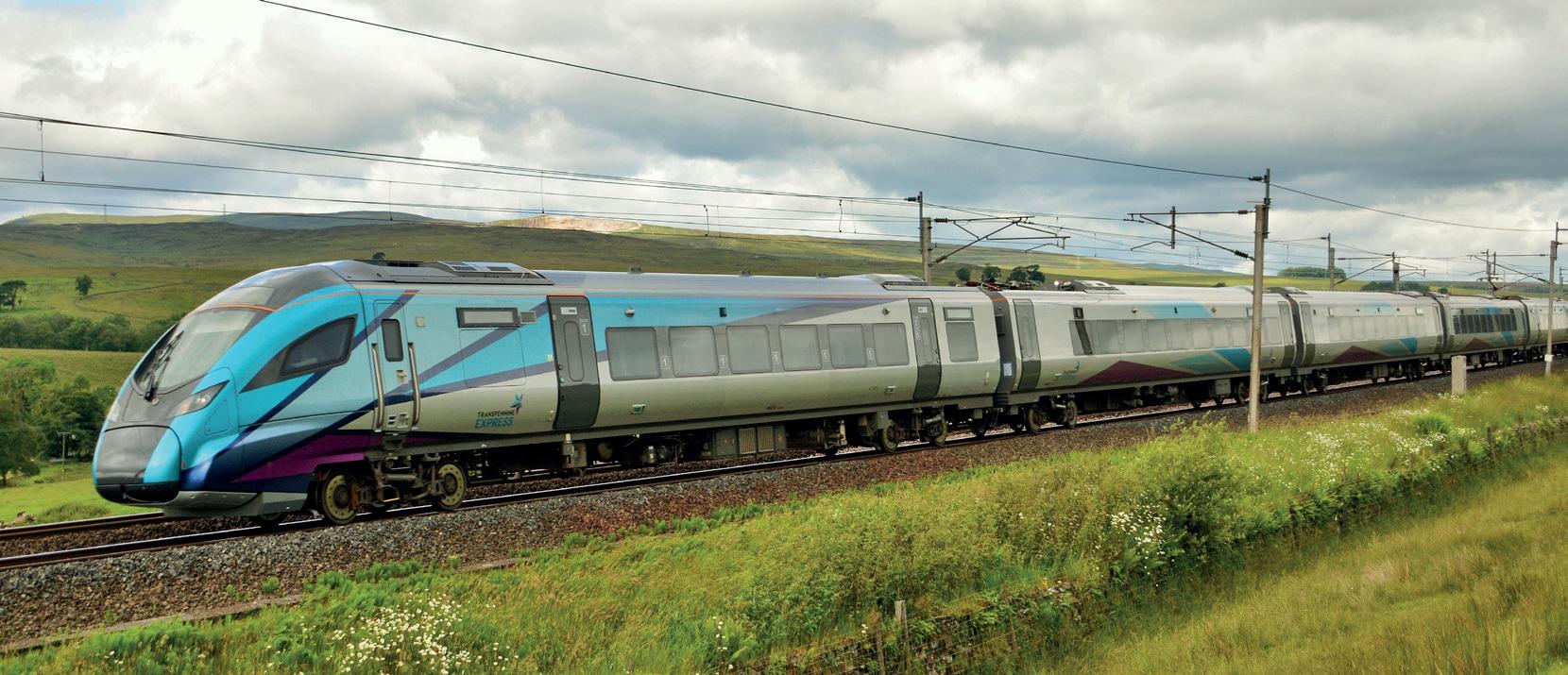
Class 802 Performance
The fleet performed better then expected over winter but in recent months reliability has been more average. The three main reasons for this were failures of Bodyside Indicator Lights (BILs), generator units (GUs) shutting down and door treadplate corrosion.
Hitachi has recently taken delivery of a new type of BILs which is expected to solve the water ingress problem affecting the current ones. The first modified
unit is now in service – the new lights operate in exactly the same way so colleagues don’t need to do anything differently. There are a variety of reasons for GUs shutting down, one of the most common being a fault code intended to detect electrical failure of components such as injectors; in fact this is too sensitive so it has been shutting engines down in response to ordinary degradation of wiring
Class 802 Battery Train Trial
As some colleagues may have heard, TPE has allowed one of our Class 802 units to be used by Hitachi and its owner, Angel Trains, for a temporary trial of battery technology. The unit, No. 802207, will not be operated by TPE in this condition but will be taken on test runs on our network in July and August.
Class 802 Safety
We have had occasional reports of luggage falling from racks and landing on passengers, sometimes causing minor injury. All colleagues are encouraged to look out for luggage that is not correctly stowed, for example
The trial involves replacing one of the three GUs with a lithium ion battery back, essentially a very large, industrialised version of the battery in an electric car. This will be used to allow the train to arrive and depart stations with no engines running even if there is no overhead line, reducing noise and emissions. The battery will be
large cases that overhang the overhead racks, or luggage piled above the top of the floormounted stacks. There are additional spaces behind back-toback seats and near the vestibules of some vehicles.
which is not actually a problem. We have agreed that Hitachi can adjust this setting to make the GUs less susceptible to nuisance alarms, and this will be rolled out in October after an initial trial.
Thirdly, a small number of both cab and passenger doors have been affected by corrosion under the floor. Hitachi has started a fleetwide check with the intention of finding and resolving this before it causes further problems.
charged by regenerative braking and also from the overhead line where available.
At the end of the trial this unit will be reverted to original condition and will re-join TPE service for the December 2024 timetable. If successful, Hitachi may make the technology available as a modification to existing fleets.
The emergency labels showing the vehicle layout and emergency equipment locations have become worn so Hitachi is now renewing them all.
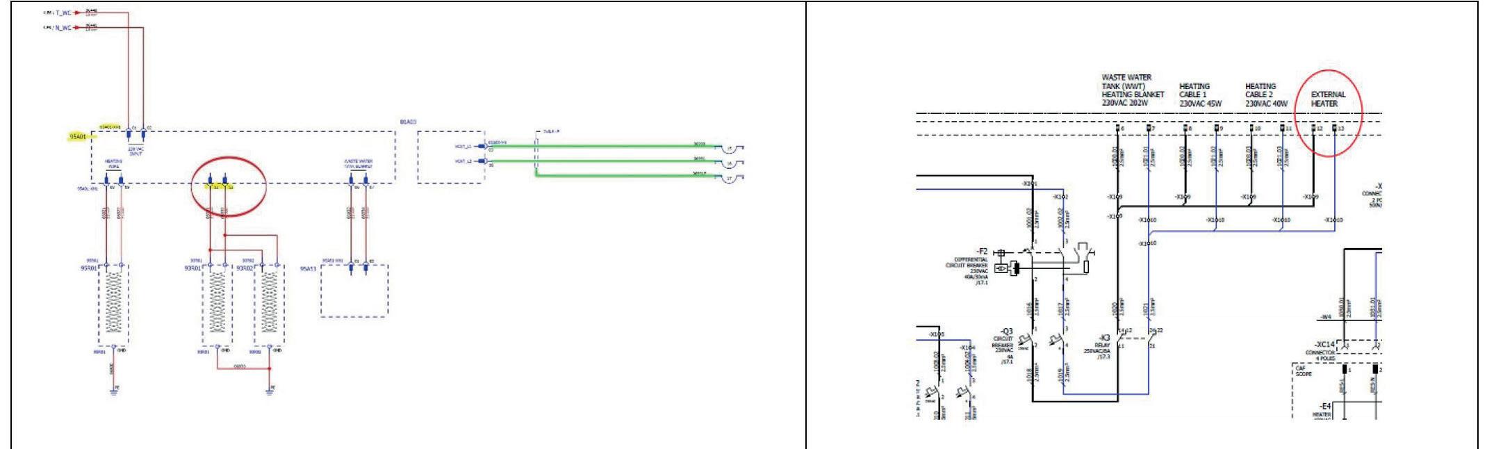
During a cold period, lack of water in a galley was reported. The fault was traced to frozen pipes not allowing any fresh water to be drawn up from the fresh-water tank. On further investigation, CAF discovered that there was no supply at the underframe connection box where the trace heaters are connected. The supply for these wires is taken from the Person with Restricted Movement (PRM) Toilet Alte control box 240V AC common supply. It has been found that on the Alte electric cupboard connector and wiring schematics the output wires with the supply for these heaters
The Class 397 Fleet sometimes suffers from rainwater ingress through the cab roof joints etc. and this is being investigating to define a permanent solution. As a temporary solution to achieve the
are located on pins 10 and 11 but at the CAF train connector and wiring schematics, the wires go to pins 12 and 13.
On the Alte schematics pins 12 and 13 are reserved for an optional external heater that is not fitted to the Class 397. Therefore, although these wires appear on the Class 397 Alte schematics, no associated wire numbers are shown which means wires are not fitted.
CAF propose to move wires from pins 12 and 13 of the connector to pins 10 and 11 and correct the CAF schematics to reflect the change.
required water tightness CAF propose using the extreme sealing tape 4412N supplied by 3m. The tape will be added around the entire join between the cab and the carbody on all units that are considered necessary. This tape has been previously used successfully on Class 397 and on different projects with successful results. The temporary solution will be applied in line with the tape manufacturers guidelines which include temperature and humidity recommendations. Any joints in the tape will have a minimum two-centimetre overlap.
Galley Fresh Water Trace Heating Wiring Correction
Cab roof temporary seal
Re-railing (lifting) jacking plate improvement
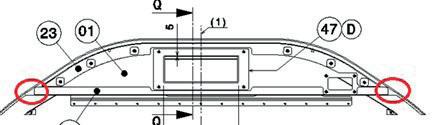
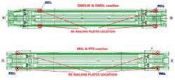
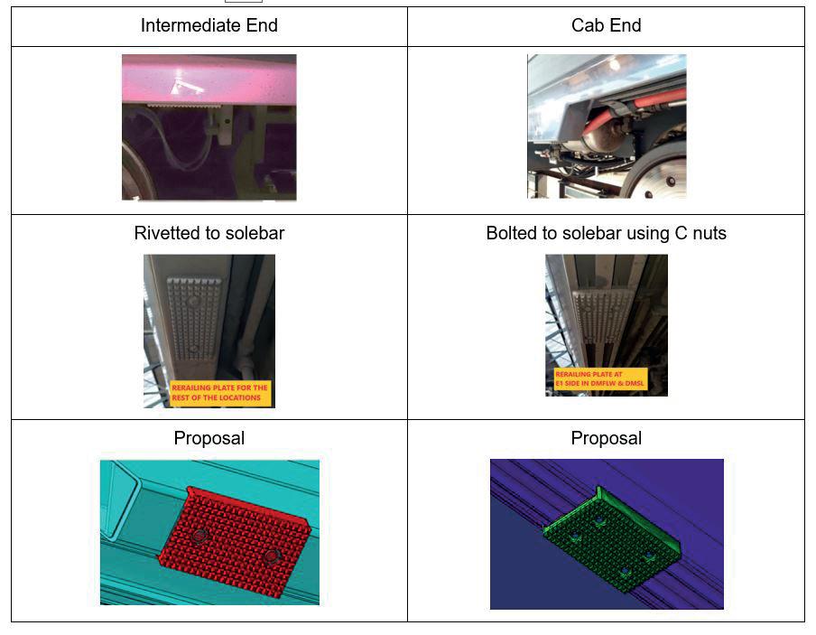
The re-railing plates on a Class 397 are located as shown. During the re-railing of a CAF unit the solebar suffered extensive damage as shown and required significant rectification before return to service. The re-railing plates on a Class 397 are an identical design at the intermediate end but differ slightly at the cab ends. The two different types are secured to the unit differently as shown. Whilst the jacking pad design is considered compliant to standards CAF recognise that rerailing activities can differ. The location and type of derailment determine the level of additional load that can be applied to the jacking pad. Therefore, following a request from the unit owners, CAF propose to improve the design of the jacking pads for the Class 397s to a more robust solution as shown. The jacking pads will be secured using the same fixing arrangements as the existing jacking pads.
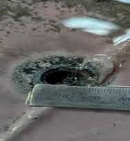
Temporary Repair to Roof Following Flashover Event
Following a flashover event, a temporary repair of the roof on 474007 in has been carried out. A similar process has been approved by TPE for use on the Class 802 Fleet. The repair consists of an Aluminium disc, Sikalex 265 and Tectyl 506 EH and is similar to the image. A procedure will now be developed to enable Alstom to carry out this temporary repair on any unit found with flashover damage to allow the unit to return to service and a permanent repair to be planned.
Train Protection and Warning System control unit trial
The Unipart Rail Train Protection and Warning System (TPWS) four control unit performs a self-test for degradation each time a track grid set to a green/clear signal aspect is passed to comply with current Railway Group Standard ‘GE/ RT8075 AWS and TPWS Interface Requirements’. There are no specific requirements that reference what or how this test should be performed but all TPWS manufacturers have achieved this by having a second smaller coil wrapped over the main TPWS aerial coil which is inside the TPWS Aerial assemblies. This in service degradation check was not a requirement prior to TPWS 4 introduction. The rationale behind conducting the in-service TPWS aerial test after a “Clear” is that there are no active TPWS loops after a “Clear” thus it is a clean time with no other track activity to affect this process being implemented successfully. The in service TPWS Aerial Test is performed using alternating TPWS frequencies of F1 - 64.25 kHz and F6 - 66.75 kHz as being able to detect these means that the four frequencies in between (F2, F3, F4 and F5) will be able to be detected.

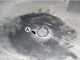
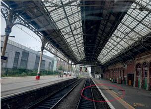
Incidents have found that the TPWS system is causing the alarm AL44004 “TPWS Antenna DC Continuity Failure” and the temporary isolation / fault lamp shown circled on the image to flash following a clear signal. The occurrence of these TPWS failures is suspected to be the result of a failure of the degradation self-test described above. The control unit sends alternating minimum (F1) and maximum (F6) frequency output test signals to the TPWS Aerial and checks that it receives it back. If the expected return signal
is not received the driver will receive a flashing Temporary Isolation Light on the control panel as an indication of signal transfer degradation until the next time the test passes. Similar faults were also detected on the Northern fleets and following investigations with Unipart, the EVO TPWS 4 control unit has been provided for trial on the Class 397. The equipment on a vehicle must meet the European directives for Electro Magnetic Interference (EMI). This means it needs to be immune to disturbance that affects an electrical circuit due to either electromagnetic induction or electromagnetic radiation emitted from an external source. This requirement is covered in EN50121 but only specified compliance down to 100KHz. Compliance in respect to TPWS is not covered as it works in the 60KHz frequency range. This means that compliant equipment on a vehicle could emit frequencies below the compliance value specified in the European Directive and it is these types of emissions that the TPWS test signal needs to overcome. One way to achieve this was to improve the signal to noise ratio of the TPWS installation. This was previously achieved by increasing the TPWS test signal strength from 80nT to 90nT. The higher self-test signal strength was more resilient to any electrical signal noise and thus ensured a higher success rate at satisfactorily completing the selftest (providing the system is found to be healthy). The higher self-test signal was still below the >90nT signal strength emitted by the track mounted grids mandated in ‘GE/ RT8075 AWS and TPWS Interface Requirements’. The 80nT self-test signal had been set using a resistor, in the TPWS Control Box. The resistor was exchanged by Unipart Rail to a 47KΩ, and modified TPWS four Control Boxes were identifiable by Modification ‘D’ status.
Class 397s and other modern fleets are still suffering from the TPWS temporary fault lights flashing
immediately following a clear signal. As a result, Unipart have developed the TPWS 4 EVO control unit given modification E status and CAF have installed it onto recent new build units without any reported issues. CAF propose to trial several of the EVO control units on Class 397 units with monitoring for 6 months. There are aspirations to increase the trial to up to four units. Leadmind will be used to monitor for the alarm AL44004 “TPWS Antenna DC Continuity Failure”. The proposed control unit provides an improvement for those situations where there is a signal degradation and is fully compatible with the one currently installed in the Northern and TPE fleets.
With the proposed TPWS EVO control unit, the standard process is for the control unit to output a test frequency at an amplitude of 90nT which must be received back within 50ms and this alternates between the two test frequencies. If the test frequency is not received back within 50ms then the control unit doubles the amplitude to 180nT to overcome the issue and sets an internal flag for the use of the large amplitude. This is achieved using a second, switchable test circuit within the control unit that can select the higher amplitude test. The next test shall only be at 90nT due to the internal flag that was set, and the test frequency must be received back within 100ms else a TPWS fault is indicated. If the test fails at 180nT then a TPWS fault is indicated. Unipart confirm that there are no functional variations between the TPWS Evo product and its predecessor and both achieve the functional requirements as defined in applicable Group and Rail Industry Standards.
Temporary removal of Wiper Intermittent mode

There has recently been a modification to the wiper system to prevent it being stuck on in intermittent mode. Unfortunately, the higher-than-expected inrush current, circa 300 Amps, when the wipers are first switched on far exceeds the specification for the intermittent wiper relay and as a result the contacts weld together and you cannot switch the wiper off at all. Then the wiper blade rubs across the glass resulting in the issue on Driver visibility. Following a suggestion from a TI and CAFs confirmation that there would be no adverse effects other than the intermittent wiper function no longer working and the wipers will not automatically switch on when the screen wash button is pressed Operational Standards and the DCC agreed that relay 90K02 can be temporarily removed to prevent the “unable to switch off wiper issue” until a permanent solution has been approved and implemented. CAF have presented an Engineering Change for a Trial of a permanent solution to return the wipers to normal operation.
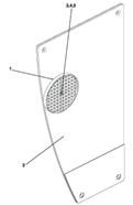
Passenger door reflector improvement
The exterior passenger door light barrier reflectors (Item 1 on image) on the class 397 are being broken when items such as luggage get caught on them during service. CAF would like to strengthen the fixing of the reflector to prevent passengers from breaking it. CAF propose adding Loctite 480 in addition to the existing fixing on the reflector to strengthen the assembly.