
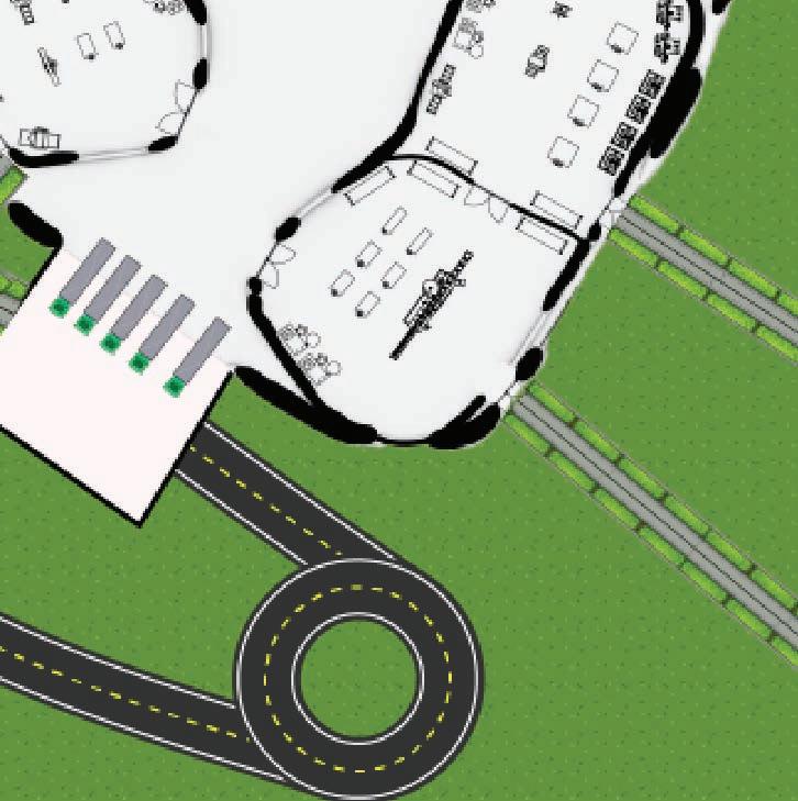
1. Carbon Capture & Processing Zone
Direct Air Capture Units:
- Machines extract CO2 from the atmosphere.
Storage & Processing Chambers:
- CO2 is compressed and stored for material production.

1. Carbon Capture & Processing Zone
Direct Air Capture Units:
- Machines extract CO2 from the atmosphere.
Storage & Processing Chambers:
- CO2 is compressed and stored for material production.
2. 3D Printing & Fabrication Hub
Conversion Facility:


- CO2 is transformed into usable materials (e.g., carbon infused concrete, graphene composites, synthetic fuels).
3. Adaptive Construction & Kinetic Integration
On Site 3D Printing Units:
- Printing adaptable architectural components that respond to environmental changes
Modular & Prefabrication Zone:
- 3D printed parts are assembled into flexible, transportable building sections.
Kinetic Component Fabrication:
Material Research Lab:
- Testing sustainable binding agents and improving CO2 based materials.


Robotic Assembly Area:
- AI driven robotic arms assemble components or adjust printed elements.


Binder Jetting & Extrusion Printing Stations:


- Printing structural elements using carbon sequestered materials.
4. Public showcasing & Educational Spaces


- Producing AI controlled blinds, ventilation systems, or structural elements that adjust dynamically.

Exhibition & Viewing Areas:

- Showcasing live 3D printing and carbon sequestration processes.


Workshops & Research Collaboration Hubs:


- Spaces for scientists, engineers, and architects to develop new sustainable techniques.


Open Spaces (Gardens & Parking Lots):
- Landscaped areas utilizing recycled paving materials and carbon infused surfaces for sustainability.
THOERY PHOLOSOPHY POSITION


Summary


Prioritizing flexibility, this modular design enables seamless future expansion through interconnected bubble like structures while maintaining adaptability with existing elements. Rooted in sustainability, it harnesses the on site carbon capture factory and incorporates smart materials with 3D printing techniques, the system allows for efficient, customizable construction with minimal material waste, creating a closed loop construction process.


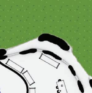
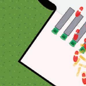
Using the bubble diagram, I developed a spatial model with appropriate scale, allowing for a well-connected and cohesive design approach with and functional areas.


The next version was applied within zones, resulting in a smaller scale, but the polka dot finish felt out of place and did not allign with my theme.


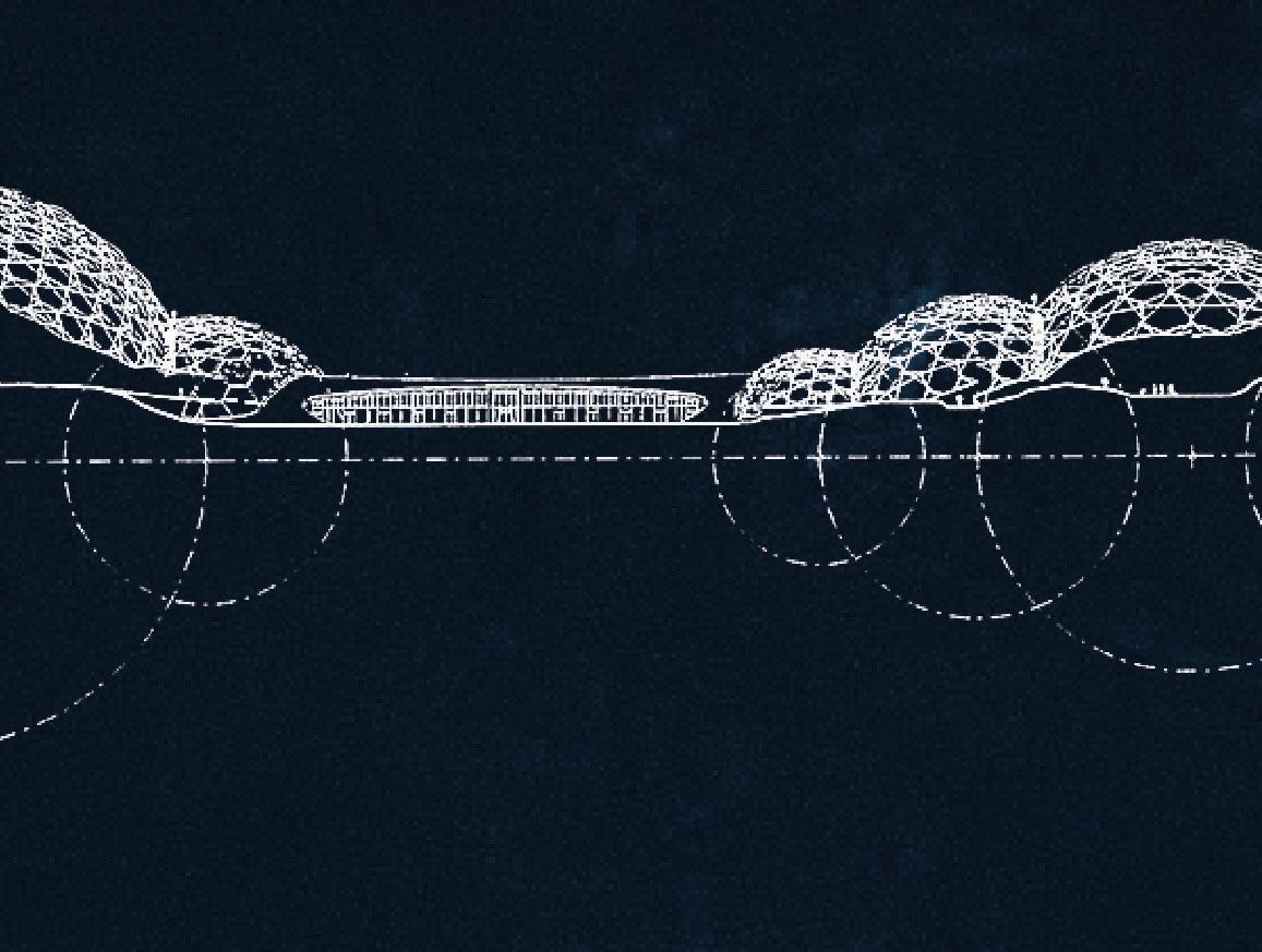
I applied a shrinkwrap modifier and other techniques to create a symbiote like facade. My first experiment, however, was impractical due to an excessively large exterior span.


The final version is much better, with a central focus on the largest dome in each zone, making it feel more symbiotic and organically integrated.


335 ETFE panels serve as skylights, maximizing natural lighting, while vents at the bottom ensure proper airflow and ventilation circulation.
3D-printed in parts and assembled on-site using carbon-captured cement, with integrated insulation.


A charred timber base frame provides construction support during facade assembly, afterward some parts will be removed, while others can be repurposed for cable management and other functions.


This project reimagines the industrial factory as a public technology hub — a space where innovation, education, and environmental responsibility converge. Rather than isolating production, the architecture reveals it, placing carbon capture systems, robotic 3D printing, and material transformation on display.
Visitors move through layered spatial experiences, Educational zones and exhibition areas invite engagement with emerging technologies, making complex systems visible and understandable. The building becomes a place of curiosity and transparency, where community members, students, and industry professionals alike can explore the potential of carbon-based fabrication and future-facing construction.


The colour coded strategy turns typical hidden systems into dynamic, expressive feature, creates a high-tech industrial aesthetic while improving accessibility for maintenance

CENTRE POMPIDOU
Stairs


Large Ventilation


Ventilation

Electrical Elements
Plumbing + Fire Control

Elevators + Escalators
Summary
I aim to mimic the Centre Pompidou's color-coded pipes, incorporating them as a distinctive feature in my design. With a carbon capture factory and a 3D printing bay, these exposed pipes will visually express the building’s functions, much like an organism’s biological systems, emphasizing the fusion of machine and biology.


Studio 3.2’s rainwater system features concealed slot drains integrated into the landscape, connecting to a subsurface pipe network that channels water to a central underground tank. With a flow rate of 27 gallons per minute per foot, compatible with Manchester’s frequent rainfall and occasional heavy downpours, the drains ensure efficient runoff collection even during peak storm events. The system is sloped to promote gravity-fed flow, preventing surface pooling. Water is stored in a 6×4×2.5m tank (approx. 60,000 liters), where it is filtered to remove sediment. This treated water is reused for greywater purposes such as toilets and workshop sinks, supporting environmental control and sustainability.


After filtration, the treated rainwater is distributed via a greywater piping network buried approximately 0.8m to 1.2m below ground, ensuring frost protection and accessibility. These pipes deliver water to restrooms, workshops, and utility zones across the project. The greywater is primarily used for toilet flushing, washbasins, and general cleaning, reducing demand on the main potable supply. The system helps close the water loop on-site, aligning with sustainable building practices and minimizing waste. The underground layout avoids visual clutter while supporting efficient flow and pressure throughout the facility, enabling seamless integration with daily operational needs.


Exhaust ducts are positioned on the roof directly above key zones requiring active air circulation. These include workshop areas, the main exhibition hall, post-processing spaces with heavy machinery, the printing bay, and the material conversion zone. The elevated duct placement enables efficient extraction of heat, fumes, and particulates, preserving indoor air quality. The ducts are powered and controlled from accessible ground-level electrical systems, allowing easy maintenance without rooftop access. This setup supports a responsive ventilation strategy tailored to the building’s varied functions, ensuring a safe, comfortable, and regulation-compliant internal environment.


The carbon capture pipes are positioned directly above the factory area, facing the southwest (SW) direction to align with the prevailing wind patterns, maximizing CO2 capture efficiency. This strategic placement allows the system to continuously extract carbon from the atmosphere, particularly during periods of strong wind flow, enhancing the building's sustainability. Controlled from accessible ground-level systems, the carbon capture pipes are designed for easy maintenance and monitoring, ensuring both efficiency and adaptability to varying environmental conditions, while contributing to the overall environmental goals of the project.


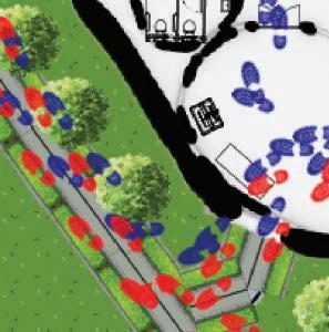
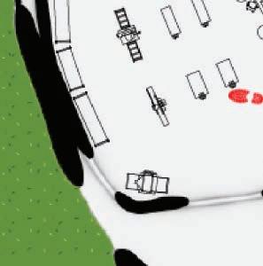
Fire Exit Path
Visitor Walk Path


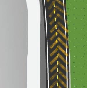
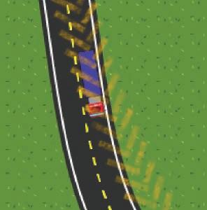
Transport Path


Policy Alignment

1. Places for Everyone (PfE)

Planning/Development Policy Reference


• Supports Policy JP-S2 (Carbon and Energy) by integrating active carbon capture systems and contributing to the region’s net-zero emissions targets through renewable energy use and sustainable materials.


2. Rochdale Core Strategy (2016–2028)


• Reinforces Kingsway Business Park’s role as a strategic employment hub, aligning with PfE spatial growth objectives through future-focused industry.


• Aligns with Policy G2 by embedding energy-efficient, low-carbon design strategies and circular material use
• Responds to Policy E2 by proposing a multifunctional factory space that promotes economic innovation and skilled employment in clean tech and additive manufacturing.


3. National Planning Policy Framework (NPPF)


• Supports Section 14 by addressing climate change through on-site carbon capture, renewable infrastructure, and passive environmental control.


• Complies with Section 15 by integrating


According to SWOT
• Excellent Connectivity
• Direct Metrolink access to Rochdale, Oldham, and Manchester city centre.
• Encourages public transport use, reducing car dependency and emissions.
• Supports Sustainable Transport
• Aligns with Places for Everyone and Greater Manchester’s net-zero goals
• Promotes flexible, year-round staffing and diverse participation in factory and exhibition functions.
• Fosters Community Engagement
• Increases public access to exhibitions, workshops, and events.
• Promotes social inclusion by linking surrounding communities to the site.
Alignment with RIBA Sustainable Outcome Guide
• Net Zero Operation Carbon
• Carbon Capture Pipes facing prevailing wind direction (SW) help actively remove CO2 from the atmosphere.
• Integration of on-site renewable energy and passive designs (ventilation ducts, slot drains, ETFE panels) reduces operational energy loads.
• Net Zero Embodied Carbon
• Use of 3D-printed materials and locally processed carbon-derived components aims to minimise transport emissions and material waste.
• Potential to use carbon-stored materials in architectural components (e.g. structural facade).
• Sustainable Water Cycle
• Potential for rainwater collection from large roof areas for use in cooling, printing, or landscaping.
• Landscape strategy may include wetlands or garderns, reducing runoff and aiding local water management.
• Sustainable Land Use and Ecology
• Masterplan includes green gaderns (green areas), native planting.
• Positioning of the factory within Kingsway Business Park helps reuse previously industrialised land rather than encroach on greenfield areas.
• Inclusion, Equity and Participation
• Public programming through exhibitions and educational access encourages local community engagement.
• Design supports accessibility, employment opportunities, and participation across skill levels.


Approved Document B (Fire Safety V2)
• For workshop and factory areas, which involve flammable materials and machinery, I have classified these as high-risk zones. I have ensured that the maximum travel distance to the nearest fire exit in these areas does not exceed 18 metres
• Circulation routes and sightlines to exits are prioritised in the printing, material conversion, and post-processing areas. Fire exit doors open in the direction of escape and remain unobstructed, with fire-rated corridors and escape routes included where necessary.
• Ensures that your design is accessible for all users, including those with mobility impairments.
• Wheelchair access (wide doors, no level change)
• Restrooms and facilities for disabled users
• Accessible paths and entrances to the building
Approved Document F: Ventilation
• Applies heavily to your factory and workshop spaces


Approved Document M: Access to and Use of Buildings
• Ensures mechanical extraction in workspaces with fumes (e.g. roof ducts).

South West Extrance View
Facts
Total Surface 39,540m2
Total Steel weight 700 Tons
Biggest Dome Diameter 125m
Column free area 15590m2

ENVIRONMENTAL DESIGN


Wind & Storm Resistance
Maximum Solar Gain & Light

Top Window Air Vent Summary
Five hexagons surrounding the central pentagon are subdivided into three triangles, creating 30 remote-controlled openings per dome. Each of these openings is also covered by triangular air cushions for enhanced functionality.
The cushions are secured to an aluminum frame and connected to an air supply system, maintaining an internal pressure of approximately 300 Pa.


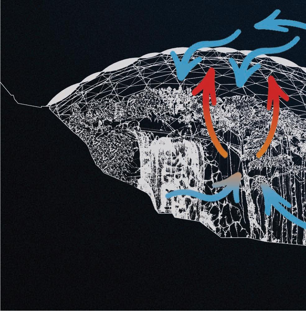


Air Flow & Ventilation


ETFE is ideal for its lightness and durability, which will be supported by an aluminum frame connecting the cushions to the facade in my project.

Uniform Temperature


The ETFE cushions use layering to control sunlight. Clearer areas bring in soft natural light for key spaces, while layered or shaded sections reduce heat and glare. This creates comfortable, well-lit interiors without relying heavily on artificial lighting.
Ventilation begins through operable vents at the base of the structure, drawing in cool air from outside. For warm air to escape, I’m exploring a top-opening system inspired by the Eden Project, which would allow natural stack effect ventilation. This setup helps maintain airflow and supports passive climate control within the space.


3. Rain - Surface Drainage


The curved ETFE surface directs rainwater smoothly across the structure, preventing buildup. Water naturally flows down to designated collection points at the base, where it can be stored or redirected for reuse. ETFE’s slippery surface also minimizes dirt retention, reducing maintenance needs over time.
4. Prevailing Wind - Pressure Response & Shielding
Manchester’s prevailing winds come from the west. The building’s rounded form and ETFE cushions help reduce drag and structural load, while the aerodynamic concrete exoskeleton deflects wind pressure and protects vents and kinetic systems.

ETFE Panel
- High light transmission
- UV resistant
- Water proof
- Self-cleaning
- Recyclable + durable
- Reduces need for artificial lighting

Carbon-captured cement
- Non-combustible
- Highly fire-resistant
- Embeds CO2 into material
- Water proof
- Strong + durable


Aluminium Ventilation
- Corrosion-resistant
- Thermally conductive
- Allows natural ventilation
- Lightweight + strong


- Prevents surface water accumulation
- Easy to intergrate with floor patterns

- Durable and low maintenance
- Enhances accessibility
Summary
This isometric section illustrates the environmental control strategy embedded in my facade and groundscape system. The ETFE membrane allows controlled daylight while minimizing heat gain, while anodized aluminum vents regulate airflow to internal spaces.
A concealed slot drain with a flow rate of up to 27 gallons per minute per foot, ensures efficient water management with minimal visual disruption, enhancing accessibility, reducing trip hazards, and maintaining a clean aesthetic. Grass zones support passive cooling and soften the microclimate. Together, these elements form a responsive envelope that balances visibility, ventilation, and drainage. The system adapts to environmental shifts while shaping a spatial experience that is both performative and tactile.


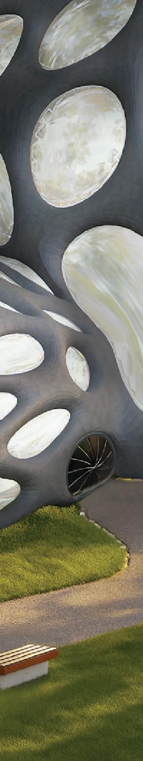
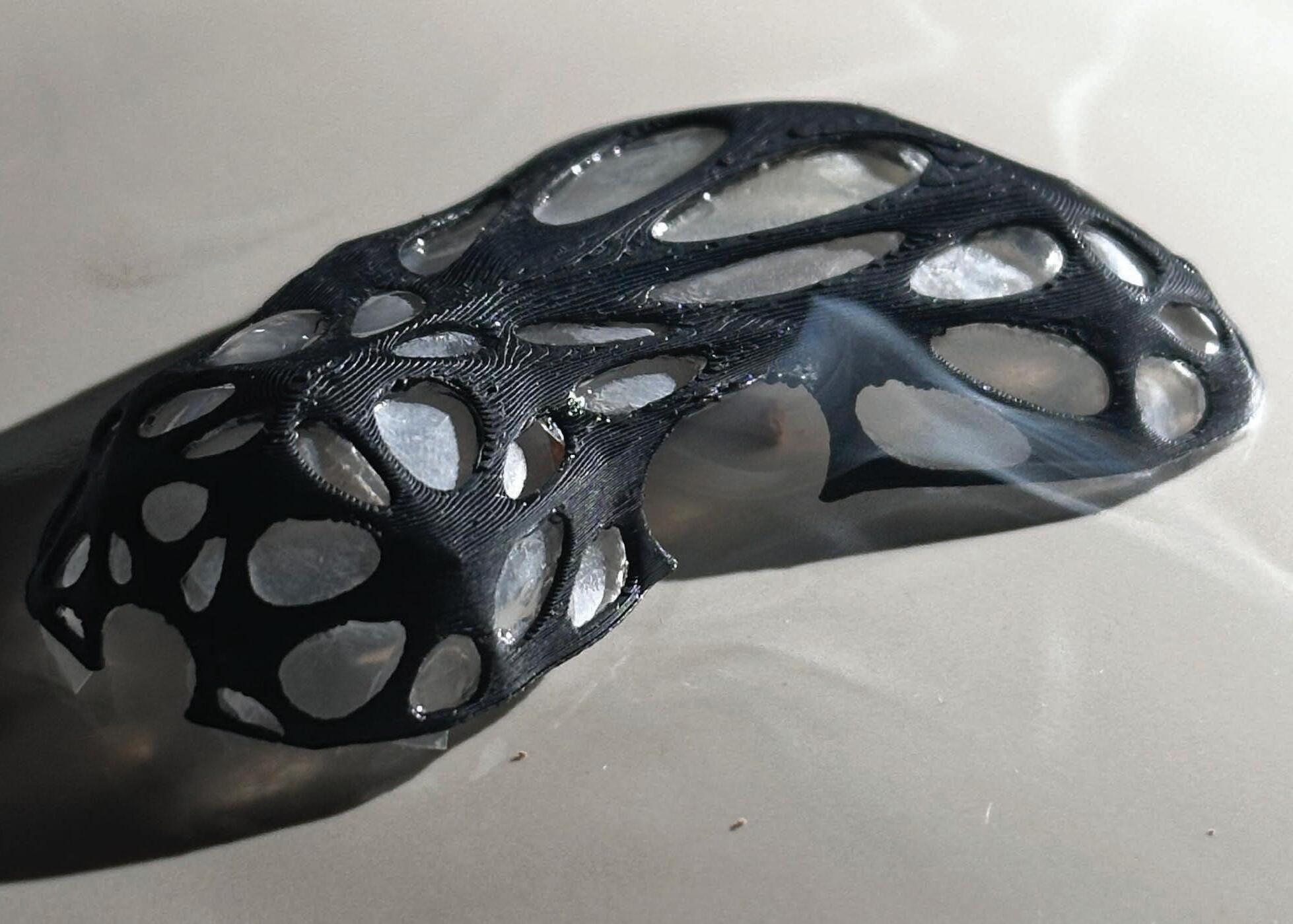
I 3D-printed a scaled model of the Voronoi structure and used acetate sheets to simulate ETFE panels. By shining a light from above, I observed how natural light would filter through the openings and cast shadows inside. This helped me evaluate light quality, visual permeability, and spatial atmosphere, informing decisions on opening sizes and material placement.
To explore surface behaviour and drainage, I conducted a basic rain simulation by pouring water over the model. This allowed me to observe how water travels across the Voronoi form, highlighting natural flow paths and accumulation zones. The results informed slope direction, drainage integration, and how the geometry can aid passive water management.

Using a smoke test on the 3D-printed model, I observed how air and smoke would naturally flow through the Voronoi opening. This helped evaluate passive ventilation effectiveness and identify how smoke might behave in the event of a fire. The test supported design decisions for safe airflow, strategic vent placement, and compliance with fire safety strategies, such as ensuring smoke can be extracted efficiently from high-risk zones.
With key aspects of the design, I carried out a series of physical tests using a 3D-printed model, focusing on how the structure performs under natural conditions. The light test helped me understand how the Voronoi geometry filters and scatters daylight through translucent surfaces, allowing me to adjust the density and layerings of openings to enhance spatial atmosphere and reduce glare The water flow test revealed how rain interacts with the building's skin, helping to refine surface gradients and passive drainage zones to avoid pooling or erosion.
In the smoke test, I examined how air and smoke would behave inside the structure, especially around key circulation areas, this directly influenced the placement of vents and informed fire safety strategies to ensure smoke can escape efficiently in high-risk areas. These iterative studies allowed me to respond to real-world conditions early in the design process and reinforce the project’s environmental and safety performance.


SHANGHAI - PROFESSOR XU (TSINGHUA UNIVERSITY)
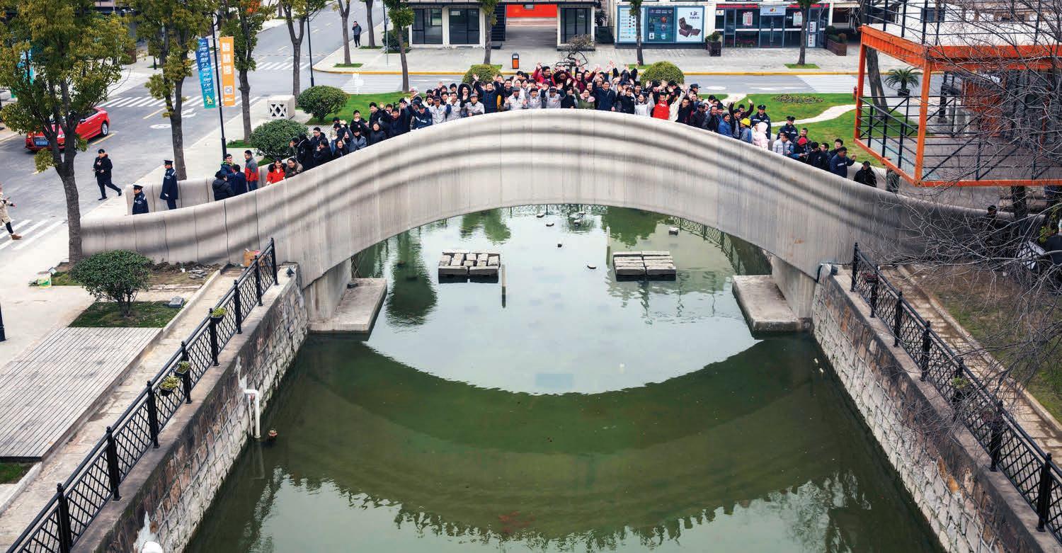
Aerial View of Project Completion

3D-Printing Process & Structural Testing


Finished Surface
AUSTRALIA - LUYTEN3D

3D Concrete Printing Home

3D-Printing Process With Crane On Site

Roof Installation
Summary
The Shanghai 3D-printed pedestrian bridge exemplifies the potential of concrete as a medium for architectural expression through additive manufacturing. Using robotic arms to layer composite concrete, the project eliminates traditional formwork and reduces material waste. The concrete mix was specially formulated for printability, allowing for precise control of flow and setting time, essential for the bridge's fluid, biomorphic form. Its layered texture reveals the fabrication process, turning structural logic into a visible aesthetic. This precedent highlights how concrete, typically associated with mass and rigidity, can become adaptable, efficient and expressive when used in a digital, toolpath-driven workflow.
Summary
Luyten 3D’s “Heptapod” house explores concrete as a responsive and versatile material through large-scale 3D printing. The project uses a proprietary printable concrete mix designed for fast setting, high compressive strength, and weather resilience, ideal for the Australian climate. Printed using a mobile gantry system, the concrete forms thick, curved walls with a ribbed, layered texture that visually expresses the additive process. This approach not only reduces labour and construction time but redefines concrete’s role in architecture, from static mass to programmable matter. The material performs both structurally and aesthetically, enabling organic forms and efficient enclosure without conventional formwork.
REASONS OF CHOICE
Emission Reduction
Carbon capture technology has the potential to eliminate up to 60% of CO2 emissions generated during cement production, particularly the unavoidable emissions released during the chemical process of calcination (Cembureau, 2024).
Environmental Responsibility
Integrating carbon capture into the construction process supports climate action by lowering the embodied carbon of materials, helping the built environment move toward net-zero targets.
Business and Reputation Value
The adoption of carbon-reducing innovations like carbon capture enhances an organisation’s sustainability credentials, meeting rising public, industry, and policy expectations around environmental leadership.
VORNOID DOME SYSTEM

The core structural concept relies on a Voronoi-inspired dome, which distributes loads organically through a network of interlocking polygonal cells. This geometry mimics cellular structures found in nature, enabling the dome to resist both compressive and lateral forces efficiently The 3D-printed concrete frame forms the primary shell of the dome, with the Voronoi pattern acting as both structure and envelope, allowing light, ventilation, and spatial articulation while maintaining rigidity. The openings can be strategically adjusted in size and density depending on the load paths, environmental needs (like daylight or airflow), and programmatic functions within the building. Foundation blocks are positioned beneath key load-bearing walls to ensure structural stability, even load distribution.
OPTION 1

On-site Modular 3D Printing

Pros:
• Easier to Print: Smaller parts reduce the risk of failure and are easier to handle on individual printers.
• More Sustainable: Less need for supports = less material waste.
• Easier to Transport: Modular parts can be printed off-site and transported to the construction site more efficiently.
OPTION 2


On-site Assembly

Cons:
• More Assembly Required: Requires time and precision to connect segments, especially for curved or organic forms.
• Structural Weak Points: Joints and seams need reinforcement and careful design to maintain integrity.
• Alignment Issues: Inaccurate joins can compromise the geometry or performance of the structure.

Pros:
• Structural Continuity: Printing as a single piece creates a seamless, unified structure with no joints or weak points.
• Reduced Assembly Time: Fewer parts mean less post-processing or on-site construction.
• Organic Aesthetic: Tree supports can create a visually striking, biomimetic internal or external frame that integrates with the design.

Cons:
• High Material Waste: Supports, even tree-type, still use extra material which is often discarded after printing.
• Longer Print Times: Large prints with supports significantly increase total print time.
• Difficult Removal at Scale: Removing tree supports from architectural scale prints is labor-intensive and risks damaging fine elements.
INTERIOR ENVIRONMENT CONTROL


MODULAR 3D PRINTED PARTS EXPLODED DETAIL 1:5


CONCIERGE ROOM SHELL


Summary
The clamp system consists of anodized aluminium top and bottom plates that securely hold flexible or rigid materials, such as ETFE, vent membranes, or even glass panels without puncturing them. These are anchored to the main frame using T-steel anchors, providing strength and long-term stability. Designed for interior environment control, the system supports modular integration of ventilation flaps, internal windows, or adaptable openings. It is also engineered for easy maintenance and replacement, allowing parts to be swapped out without dismantling the entire assembly.

PHYSICAL MODEL DETAIL 1:5

PHYSICAL MODEL DETAIL 1:5 (IN PARTS)
I 3D printed the components for the 1:5 model, including the aluminum clamps, athough they are in pla material, the aluminium clamp can't 'clamp' with the mealability. Despite that, This allowed me to evaluate the fit and functionality of the clamps in the design.

PHYSICAL MODEL DETAIL 1:5 (BOTTOM VIEW)
I am very pleased with the result of the 1:5 scale model, as it effectively demonstrates the functionality and fit of the 3D-printed components, including the aluminum clamps. The assembly process was smooth, and the model accurately reflects the intended design, providing valuable insights into the practical application of the structural elements.


Construction Phase


The Torre de Especialidades in Mexico City uses prefabricated, interlocking modules, lightweight and easily transported to create its vornoid façade. This modularity supports efficient delivery and on-site assembly, reducing construction time and disruption. For Studio 3.2, this informs a strategy of halved, pre-printed concrete components that join seamlessly on-site, enhancing constructability. Like the Torre, this approach allows controlled off-site fabrication under quality assurance, aiding in approval processes and safety compliance. It also simplifies logistics, reduces labour intensity, and aligns with sustainable construction goals, fulfilling social responsibility through minimal waste and efficient resource use.
STAKEHOLDERS + DESIGN TEAM
NETWORK DIAGRAM
COMMUNITY / END USERS
Through Engagement Workshops
CONTRACTOR
For Construction & Cost Control
SUSTAINABILITY CONSULTANT
Aligns with ESG and RIBA Goals
CLIENT / DEVELOPER
For Approvoals & Feedback
ARCHITECT
Design Vision and Delivery
MEP ENGINNEER
For Climate Control + Vent Systems
COST + COST CONTROL
MODULAR PRINTING VS LAYER PRINTING
PLANNING AUTHORITY
Submits For Approval
Summary
FABRICATION SPECIALIST
Material Tolerances + Jointing
Sources Clamp Systems, ETFE Replacements
STRUCTURAL + CIVIL ENGINEER
Advises on Form + Load Strategy
The architect coordinates with engineers, consultants, and fabricators to deliver a sustainable, regulation-compliant design. Stakeholder collaboration ensures smooth approval, technical integration, and community benefit.
BUILDING + DEVELOPMENT CONTROL APPROVALS
• FIRE SAFETY HIGHLIGHTS
• High-risk zones (e.g. workshop, printing bay, post-processing) will have fire exits within 18m, meeting UK Building Regulations for escape distances in high-risk areas.
• Fire-rated corridors and doors opening in the direction of escape are integrated for enhanced safety.
• The external and internal structural walls are made of 3D-printed carbon cement, with 1000mm thickness on each side, meeting fire separation requirements for non-loadbearing fire-resisting walls (4 hours), enhancing passive fire protection.
• PLANNING PERMISSION
• Access and transport integration, with pedestrian links and proximity to Kingsway Business Park tram stop.
• Environmental performance with low-carbon construction and sustainable drainage considered early in the design.
• No overshadowing or visual dominance of neighbouring sites.
• Designs to stay within local plot ratio and site coverage expectations.
The design aligns with key UK Building Regulations, including structural safety (Part A), fire safety (Part B) with 100mm fire-resistant cement walls and clear 18m escape routes in high-risk zones, and accessibility (Part M) with step-free internal circulation Energy and ventilation strategies meet Part L and F standards. All 3D-printed components and modular systems are being developed with regulatory approval in mind.
and
2. Assuming daily setup, maintenance, and 2 shifts per day (16 hours/day): Model Filament: 110,550 Tonnes
Modular 3D printing, the project would take around 3.9 years with one printer as parts are produced off-site and assembled later. In contrast, full-scale layer printing would take around 7.9 years, due to continuous printing on-site and the need for support structures. However, using multiple printers can significantly reduce printing time for both methods, allowing for a more efficient construction timeline.
CONTRACT DOCUMENTS
SUSTAINABILITY CLAUSES AND COMMITMENTS:
Align construction with sustainability goals, minimizing waste and maximizing material efficiency per UK regulations.
MATERIAL IMPACT:
Use carbon-capture cement for the building shell and interior walls, ensuring minimal environmental impact with certified suppliers.
CARBON REDUCTION:
Reduce 60% of CO2 emissions from cement production using carbon-capture technologies.
WASTE MANAGEMENT:
Optimize material use with 3D printing, ensuring waste is managed and recycled per UK standards.
Phase 1:
Site preparation, including foundation work with modular concrete blocks to support the structure's weight.
Phase 2:


3D printing of the carbon-capture cement shell (dome) with careful planning of support structures, such as the aluminum clamps and steel anchors, for stability during printing.
Phase 3:
Installation of ventilation and interior environmental controls, integrating advanced materials like ETFE for flexible façade and ventilation openings.
Phase 4:
Internal space planning, including workshops, exhibition areas, and control systems for temperature, airflow, and moisture.
Phase 5:
Final testing, including fire safety and structural integrity checks before opening.


Modular Design: The system is designed for future adaptability, with modular structural elements can be added and allow easy modification of space layout.


Re-Use of Materials: 3D printing waste material can be repurposed (walkpaths), ensuring the building can be deconstructed or modified without significant waste.
Sustainability Focus: Energy-efficient systems and materials ensure long-term performance while allowing updates to meet future environmental regulations or innovations.
Design for Disassembly: The resin filled T-anchor can be de-resin using chemical solvents, this makes the whole stucture can be recycled or repurposed.

ETFE Panels
Openable skylight


The Voronoi dome can accommodate expansion through additional modules, either for structural or functional growth as demand increases.
Flexible Structure: Adaptation of Systems:
The internal systems (openable sky windows, fixed glass windows, and ventilation vents, shaft doors) are scalable to handle increasing production demands or changes in use over time and specific needs.
The spatial layout allows non-structural interior spaces to be adapted for different uses, from education zones and display area, to production and workshops, as needs evolve.
The project adopts a phased construction strategy, beginning with core structural modules using 3D-printed carbon-capture cement. The use of modular assembly and aluminium clamp systems ensures flexibility, enabling future expansion, adaptation, and ease of maintenance. Through physical modelling and testing, the design has proven its practicality and adaptability. Reflecting on this process, it demonstrates a forward-thinking approach where construction aligns with sustainability, reuse, and long-term evolution of the building.


Width: A minimum clear width of 850mm, accommodating up to 100 occupants, as recommended for safe evacuation.
Opening Mechanism: Doors open in the direction of escape and are fitted with panic bars or push pads, allowing immediate egress without the need for keys or codes.
Signage: All exits are clearly marked with illuminated signs complying with BS EN ISO 7010 standards, ensuring visibility even in low-light conditions.
Fire Detection and Alarm Systems: Fire detection and alarm systems will be implemented in the every concrete structure to provide early warning and facilitate prompt evacuation.


In alignment with UK fire safety regulations, all high-risk zones within the project have been equipped with additional exits, ensuring that the maximum travel distance to a safe exit does not exceed 18m. This adheres to the guidelines set forth in the Regulatory Reform (Fire Safety) Order 2005 and the Building Regulations 2010, which stipulate such distances to facilitate prompt evacuation in high-risk areas.


SECTION 1:200 (NORTH)


ELEVATION 1:200 (SOUTH)


ELEVATION 1:200 (WEST)