HALCYON HOUSE
TATIANA WILLIAMS DESIGN 6.2
PROFESSOR HUFFMAN SPRING
Part 1 Building tyPe
Part 2 Site + context
Part 3 idea/Parti generatorS + ProceSS
Part 4 Program
Part 5 Parti develoPment / archietctural SySrtemS
Part 6 Building code analySiS
Part 7 Preliminary Schematic deSign
Part 8 SyStemS reSearch + develoPment
Part 9 deSign devloPment / detailed drawingS
Part 10 detail elevation + Section
Part 12 3d viewS
Part 13 PhySical modelS
BUILDING TYPE - PART 1
CASE STUDIES
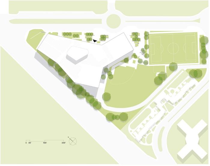
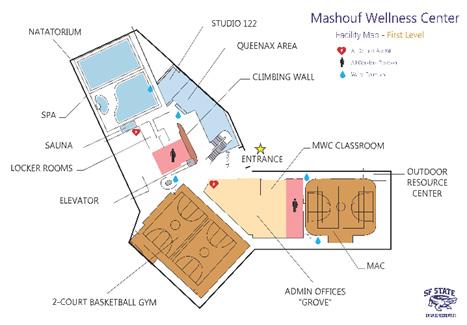
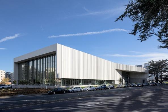
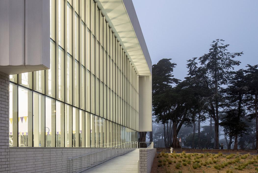
MASHOUF WELLNESS CENTER
Architect: WRNS Studio
Location: San Francisco
Year: 2017
Size: 118,670sqft
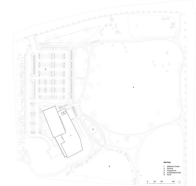
CONNECTIONS TO SITE & CONTEXT
Located at the prominent intersection of the San Francisco State University’s campus gateway. This facility connects the heart of campus and presents the building’s public face to its community.
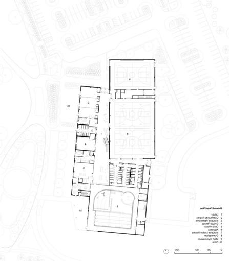
OPERATIONAL PROGRAM SOLUTION & INNOVATIONS
Visitors enter the building in a 2-story mixer space with a climbing wall that serves as an active backdrop. Glazed rooftop “lantern” that provides natural light to the main lobby and a more organic climbing experience.
ENVIRONMENTAL RESPONSES & INNOVATIONS
Recognizing the relationship between notions of wellness and sustainability, the MWC is targeting LEED Platinum and models sustainability in a building type that has historically consumed large amounts of energy and water.
Strategies include a pool discharge and on-site greywater system for collecting and treating water for landscape irrigation and toilet flushing, saving up to 600,000 gallons of water a year. A displacement system, LED lighting, and photovoltaics help offset 33% of the building’s energy consumption and 25% of the building’s energy cost. Over 90% of the construction waste was diverted, eliminating debris from Landfills.
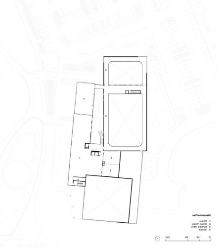
CIRCULATION NETWORK IN PLAN & SECTION


STRUCTURAL SYSTEMS / MATERIALS
Steel beams
CLADDING SYSTEMS / MATERIALS
- Exterior glazing
- Brick
- Metal Paneling
LIST OF PRIMARY & SECONDARY PROGRAM SPACES
- Natatorium (swimming pools)
- Multipurpose Rooms
- Climbing wall
- Lobby - Fitness Area
- Lockers
- Two Court Gym
- Multipurpose Activity Court Gym (MAC)
- Admin - Running Track
- Cardio Fitness
- Weight Training
- Racquetball Courts
BUILDING TYPE - PART 1
CASE STUDIES
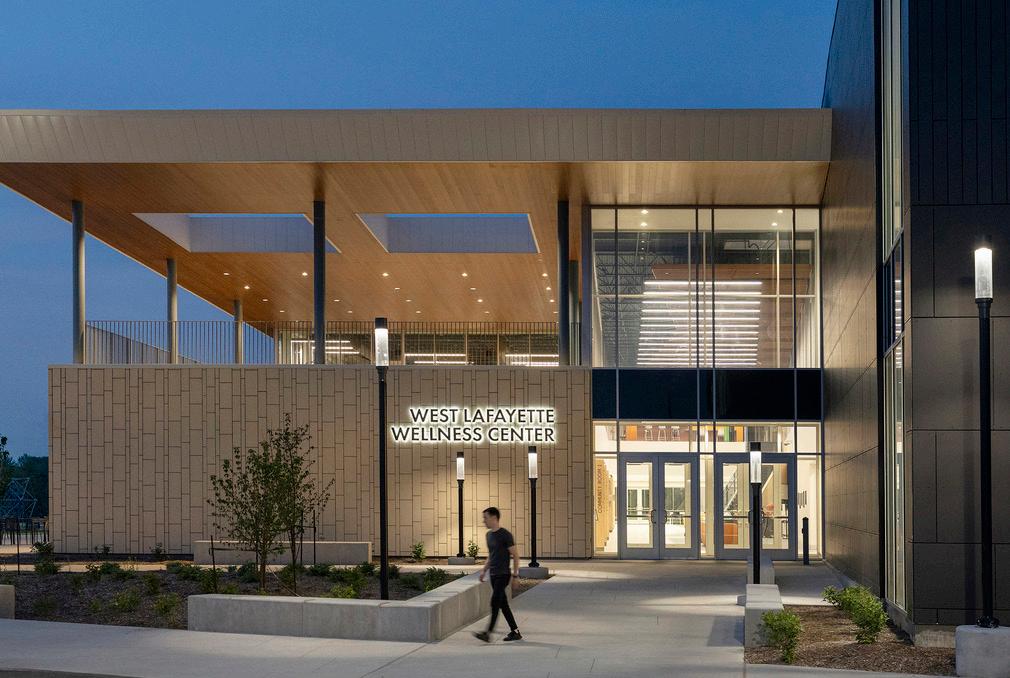
WEST LAFAYETTE WELLNESS CENTER
Architect: Perkins & Will
Location: West Lafayette, Indianna
Year: 2021
Size: 70,000 sqft
CONNECTIONS TO SITE & CONTEXT
The wellness center is surrounded by trees and green life while still connected to the surrounding areas.
LIST OF PRIMARY & SECONDARY PROGRAM SPACES
- Lobby - Community Rooms - Inclusive Restrooms - Group fitness - Child watch
Aquatics - Inclusive Locker Rooms
Gymnasium - MAC Gymnasium - Patio - Running Track
Terrace
Fitness
CIRCULATION NETWORK IN PLAN & SECTION
The wellness center has a linear circulation path.
OPERATIONAL PROGRAM SOLUTION & INNOVATIONS
All-inclusive environment, engaging with diversity, tailoring spaces to meet the needs of certain groups without leaving out others. Some of these innovations are gender-neutral bathrooms and changing rooms and differences in age, ability, and race.
Meeting rooms send wireless signals to hearing aids set to a predetermined frequency, allowing hearing-impaired visitors greater ability to adjust their personal devices to their liking while working within the volume of the room.
Workout facilities feature adaptive fitness equipment and handcycles to allow people with mobility constraints to get the same level of workout as others.
The pool, meanwhile, is designed for accessibility, with three forms of entry, including a zerodepth entry ramp for wheelchairs.
Principles of Universal Design – such as clear wayfinding, an indoor child watch area, and wider doors for sports wheelchairs – were implemented throughout the building to allow individuals and families of all ages and abilities to use them.
CLADDING SYSTEMS / MATERIALS
- Metal Paneling
- Timber
- Exterior glazing
- Stone
STRUCTURAL SYSTEMS / MATERIALS
Steel Construction
ENVIRONMENTAL RESPONSES & INNOVATIONS
Energy efficiency in the windows and doors that are installed are low-emissivity and energyefficient lighting.
Water efficiency reduces the amount of water being used in the building, which can be done by installing water-saving fixtures and reusing water.

BUILDING TYPE - PART 1
CASE STUDIES
KANEKA WELLNESS CENTER
Architect: Kengo Kuma & Associates, TAISEI DESIGN Planners Architects & Engineers
Location: Takasago, Japan
Year: 2021
Size: 6,727 sqft (625 m2)
CONNECTIONS TO SITE & CONTEXT
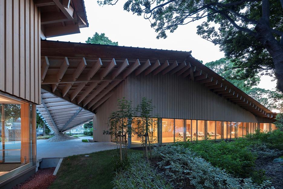
Nestled between the trees of Takasago, Japan the wellness center faces northwest. The main entrance is located on the south of the site. The wellness center is built to accommodate the nature encompassed around it. The purpose of this building is to prioritize the employee’s welfare and health outcomes. The facility provides routine medical and check-ups for Kaneka employees.
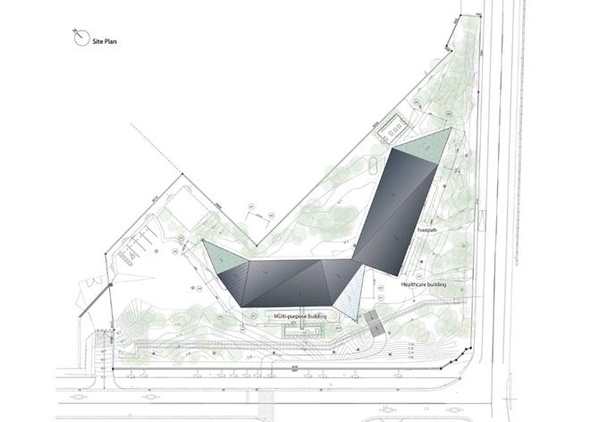

CIRCULATION NETWORK IN PLAN & SECTION
The orientation of the building makes for an interesting exterior circulation. However, the interior circulation is linear. The building on the west of the site is for multipurpose use and the building on the right is for health care. The entrance to the building is at the southwest of
LIST OF PRIMARY & SECONDARY PROGRAM SPACES
- Relaxation
- Warehouse
- Multipurpose rooms
- Kitchen
- Training Space
- Meeting space
- Lobby
- Treatment rooms
- Examination rooms
- Resting space
- Counseling rooms
- Dentist
- X-ray room
- Dressing rooms
OPERATIONAL PROGRAM SOLUTION & INNOVATIONS
The design goal was the construction of buildings surrounded by greenery, preserving as many existing trees as possible.
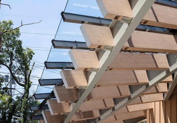
STRUCTURAL SYSTEMS / MATERIALS
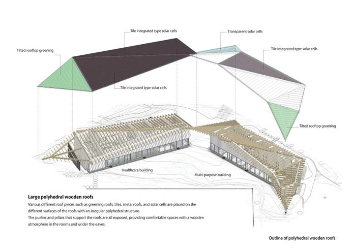
The structural material is wood. Various roof pieces such as green roofs, tiles, metal roofs, and solar cells are placed on the different surfaces of the roofs with an irregular polyhedral structure. The purlins and pillars that support the roofs are all exposed, providing comfortable spaces with a wooden atmosphere in the rooms under the eaves.
ENVIRONMENTAL RESPONSES & INNOVATIONS
After the existing trees were 3D-scanned, data was generated on them to identify their positions. Tree felling, mainly of invasive alien species of trees, was carried out to preserve tree species suitable for this area.
Tile-integrated type solar cells, transparent solar cells, and green roofs are integrated into the polyhedral roofs. This attaches different environmental technologies to different roof sides, giving various expressions of the roof. Deep eaves and great insulation systems helped achieve net-ZEB, an energy balance of zero.
CLADDING SYSTEMS / MATERIALS
- Wood
- Glass
The external insulation and double ventilation method for wooden construction developed by Kaneka for detached houses was adopted for these medium-sized buildings to install a system that changes ventilation routes according to outdoor air temperature.
PROJECT OVERVIEW
Objective
the wellneSS center PayS SPecial attention to the mind, SPirit, and Body the Program throughout the Building SeamleSSly incorPorateS BioPhilia and green SPaceS that PoSitively affect the PhySiological State of mind. green SPaceS Stimulate creativity, foSter a SenSe of connection, and even Promote Better SleeP a green SPace createS a Peaceful Sanctuary for emotional Balance and well-Being. the wellneSS center foSterS Social connectionS, educateS on SuStainaBility, and PromoteS holiStic well-Being. additionally, it encourageS green living, BeautifieS urBan SPaceS, and SuPPortS local BiodiverSity, creating a healthier and more connected environment
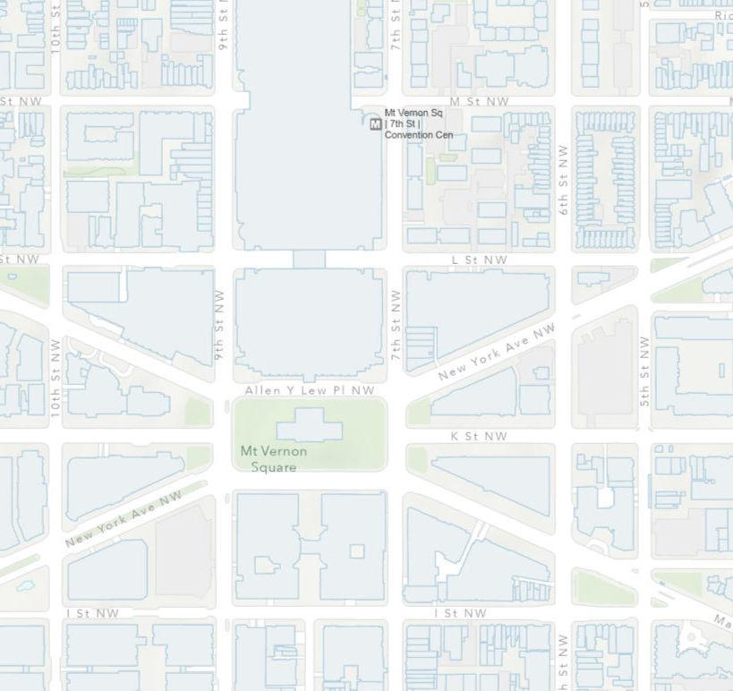
PrOject LOcatiOn Overview
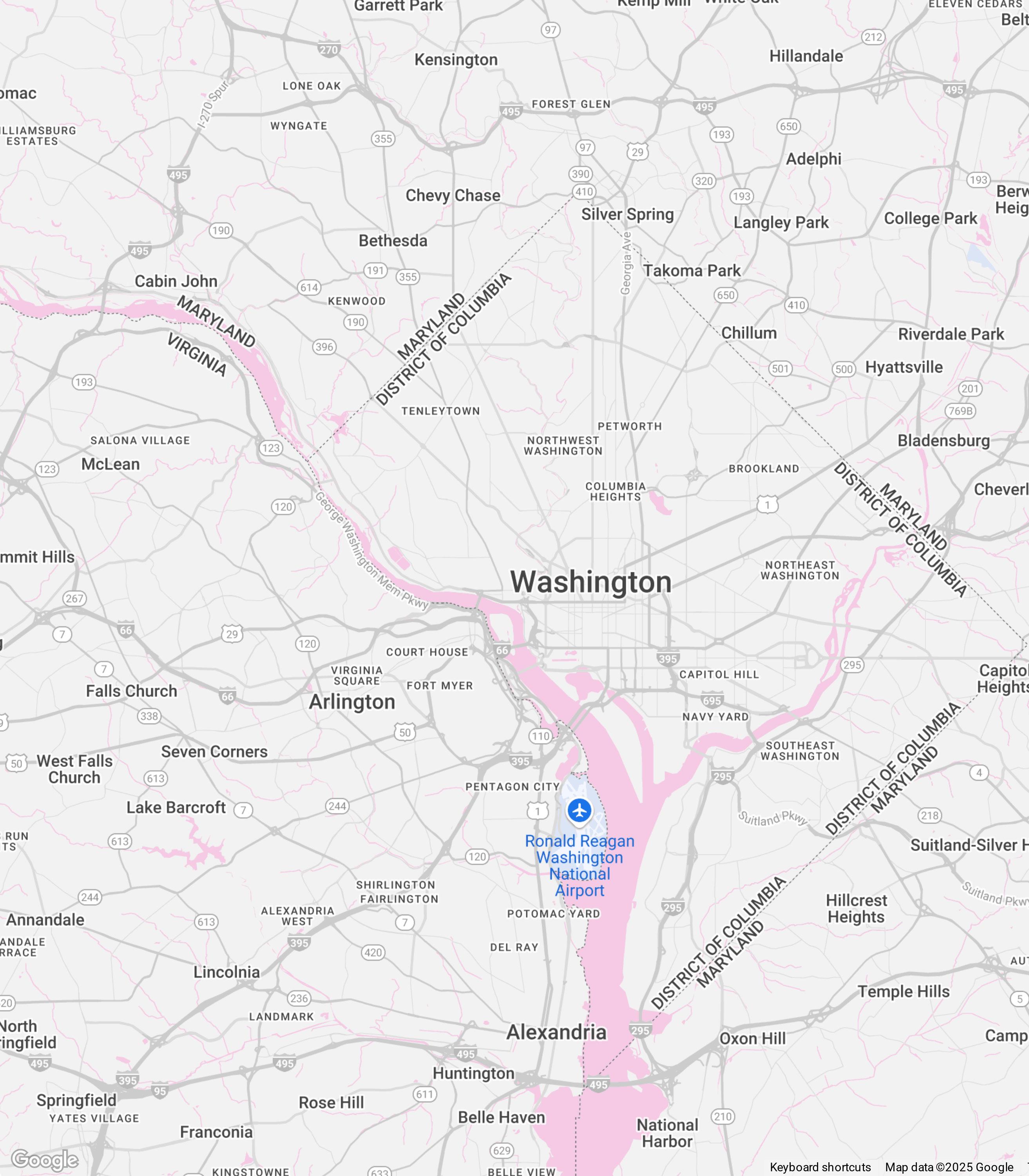
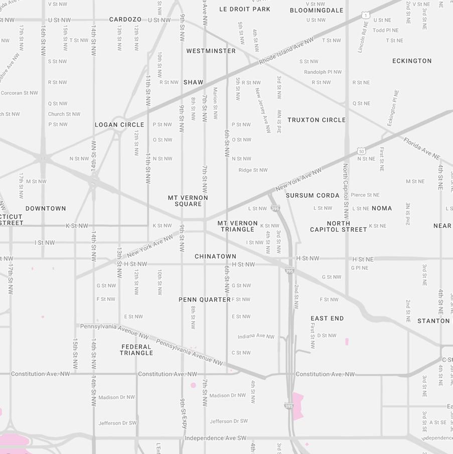
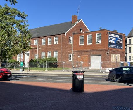
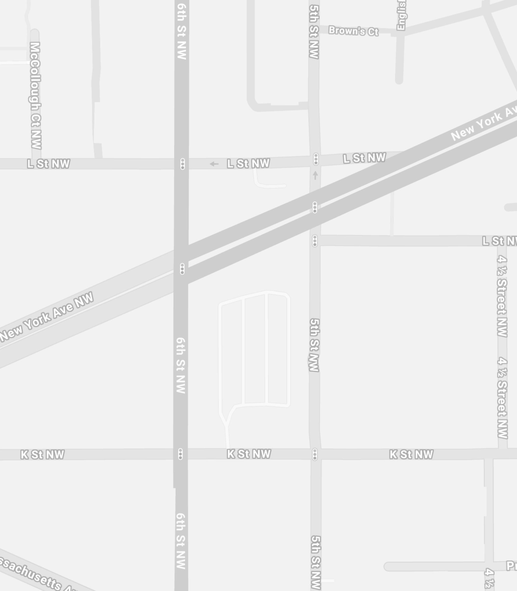
Site: 1001 6th St nw, waShington, dc 20001
the Site iS located to the eaSt of the convention center in d.c. the current uSe of the Site S a Surface level Parking lot
waShington d.c. iS the diStrict of columBia and iS known aS the caPital city and federal diStrict of the united StateS the city S on the Potomac river, Bordering the StateS of virginia and maryland. it iS defined By neoclaSSical monumentS, BuildingS, muSeumS, and Performing artS venueS.
PrOject refLectiOn
if there waS more time to comPlete the Project i would take the jurerS commentS into conSideration and do more reSearch into BioPhilia. which SPecieS of PlantS aBSorB more carBon dioxcide, incorPorate PlantS Strategically into the facade aS i did on the interior of the Building oiverall, i think my Project achived what i wanted it to and that waS to incorPorate an aBBundance of PlantS to Bring a PrecenSe of calm aS well aS the ProgramS within the Building to feel like a SPace that all are welcome a greenary huB within itS denSe urBan context.


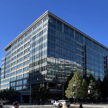
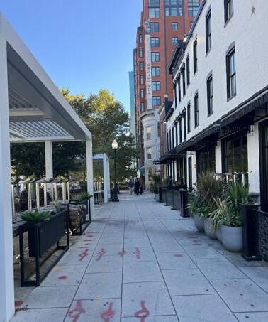
arnold + Prter kaye
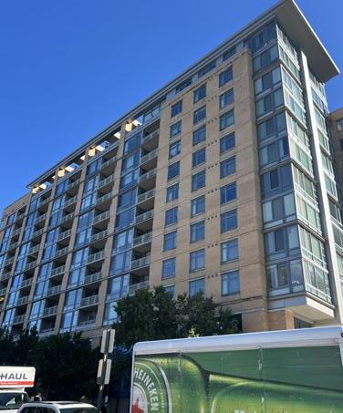
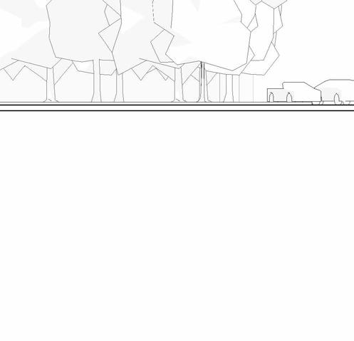
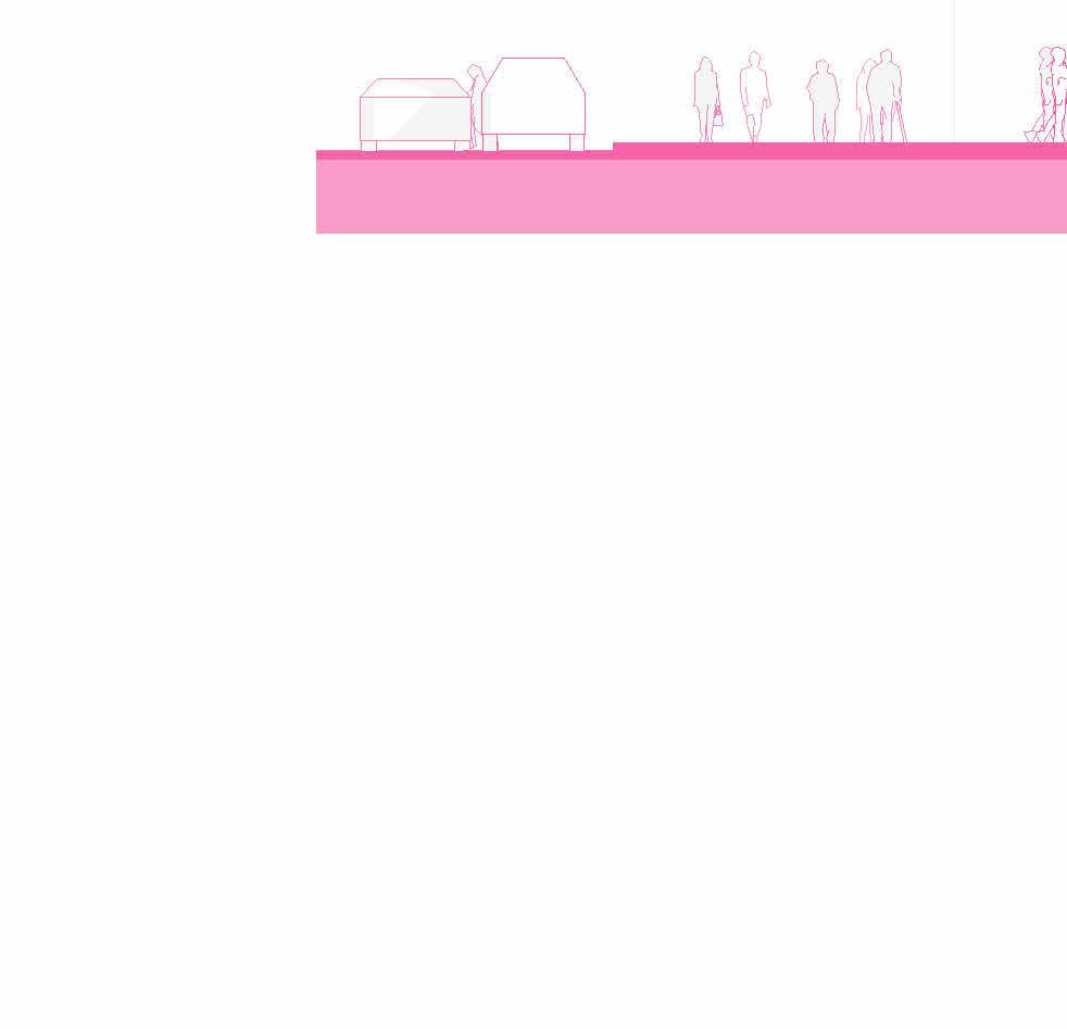
PedeStrian StreetScaPe
ZONING REQUIREMENTS CONSTRAINTS
LOCATION: Washington, D.C.
DISTRICT: Downtown, Mount Vernon Triangle Intersection
SITE LOCATION: 1001 6TH ST NW, WASHINGTON, D.C. 20001
ZONING: D-5-R Downtown
CURRENT LAND USE: Parking lot
WARD: 6
ZONING & BUILDING DEVELOPMENT STANDARDS
SITE SIZE: 116,043 SQFT
FLOOR AREA RATIO: minimum 3.5; Maximum 6
GREEN AREA RATIO: 0.2
HEIGHT LIMITS: 110 ft if R.O.W. determining height is <110 ft. wide; 130 ft if > 110 ft. wide
SETBACKS: Not regulated except in Mt Vernon Triangle Principle Intersection Sub-Area
ALLOWED LAND / BUILDING USE: Permitted high-density commercial and mixed-use development through requirements and incentives for residential use.
PARKING & BICYCLE REQUIREMENTS: NONE
FRONT TO BUILD (FT): 75% within 4ft of build-to-line, to a height of 15ft
MAXIMUM LOT OCCUPANCY: NONE
OPPORTUNITIES


green roof SyStemS to manage Stormwater drainage. height limit of 110ft if Building S more than 140ft wide. floor area ratio: minimum of 3.5 maximum of 6. green area ratio: 0.2 front to Build 75% within 4ft of ProPerty line. Set Back on mt vernon SQ triangle interSection. the Site occuPieS an entire Block which allowS for freedom of focal PointS and area Plaza oPPortunitieS, dc iS known for itS walkaBility and itS PedeStrian PlazaS terraced green SPaceS to act aS alternative outdoor gathering SPcaeS
IDEA / PARTI GENERATORS - PART 3
PARTI DEVELOPMENT
SOLid/vOid deSign actiOnS tyPOLOgieS/deviceS
addative / Subtractive Layered carved POche addreSSing the urban edge PLinth terrace Subtractive grOund fLOOr terraced Stair
CIRCULATION + PROGRAM - PART 4
BUILDING PROGRAM
WELLNESS
RETAIL
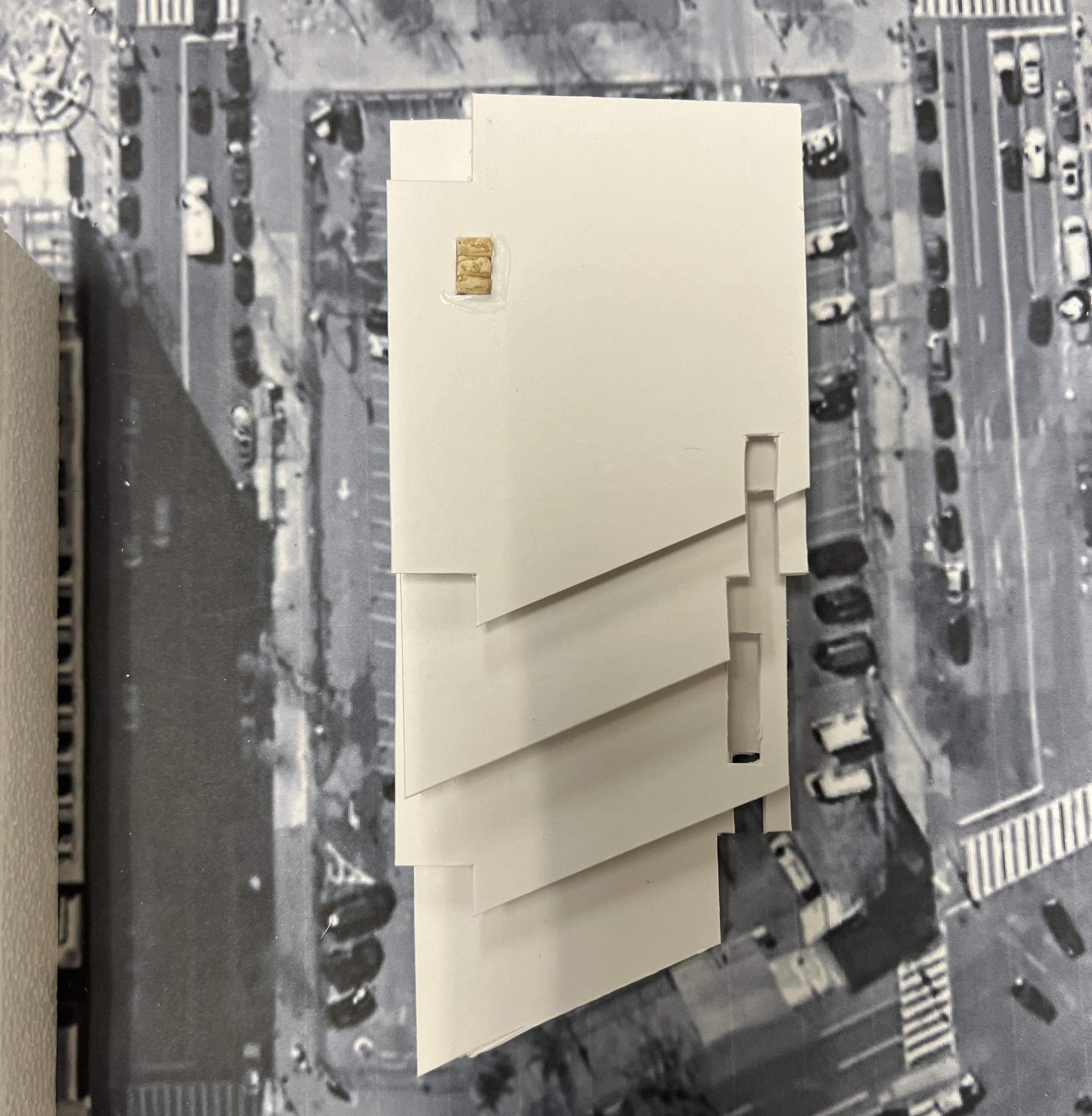
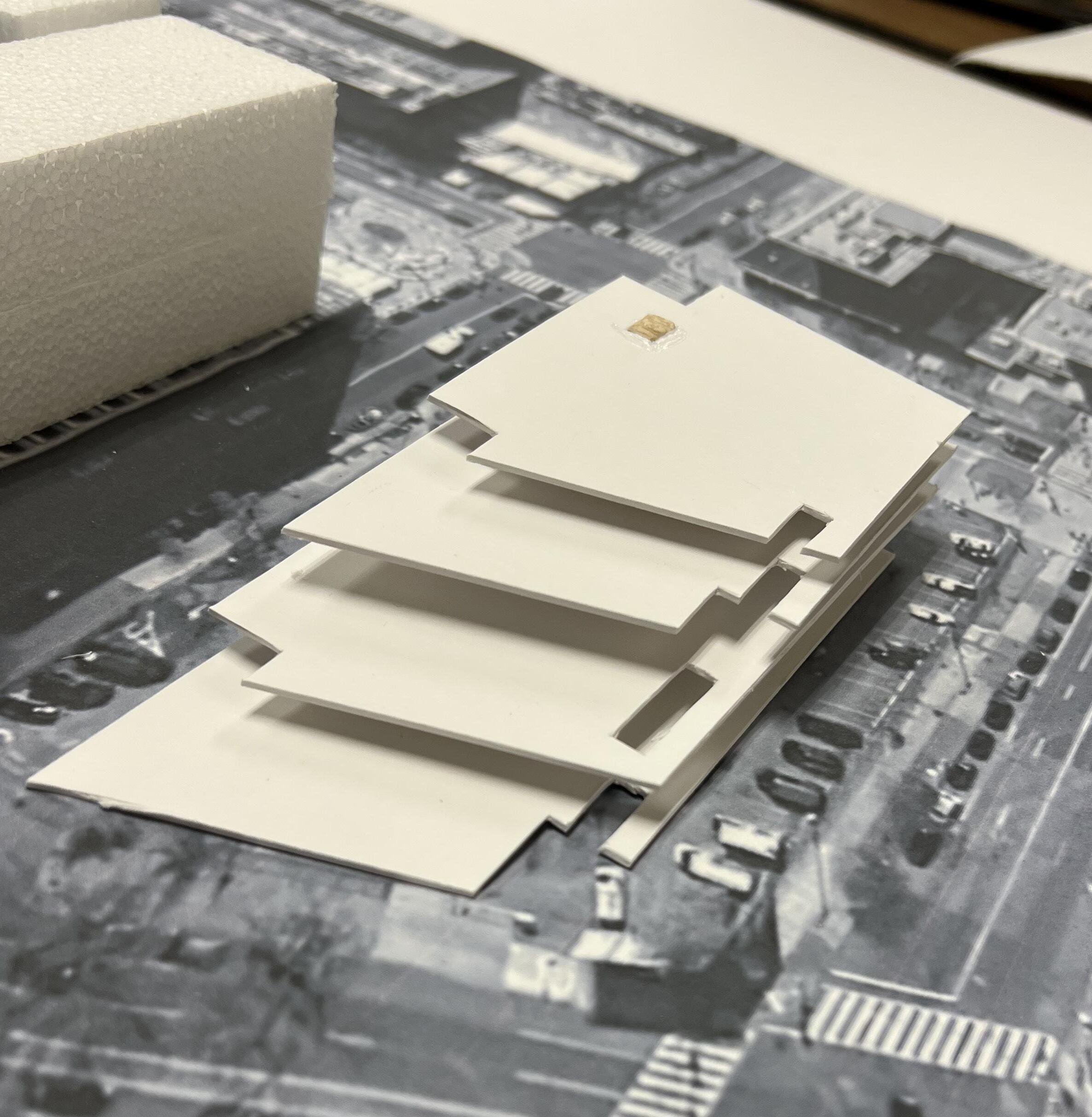
PARTI
CONCEPT MODEL
occuPancy claSSification
BuSineSS grouP B - clinic
BuSineSS grouP B - urBan kitchen / cafeteria
mercantile grouP m - clothing donation center, cafe, hair Salon training and Skill devloPment not in a School or academic Program (thiS Shall include, But not Be limited to, tutoring centerS, martial artS StudioS, gymnaSticS and Similar uSeS rgardleSS of the ageS Served and where not claSSified aS a grouP a occuPancy)
Building height & Size: ul
tyPe 1 conStruction
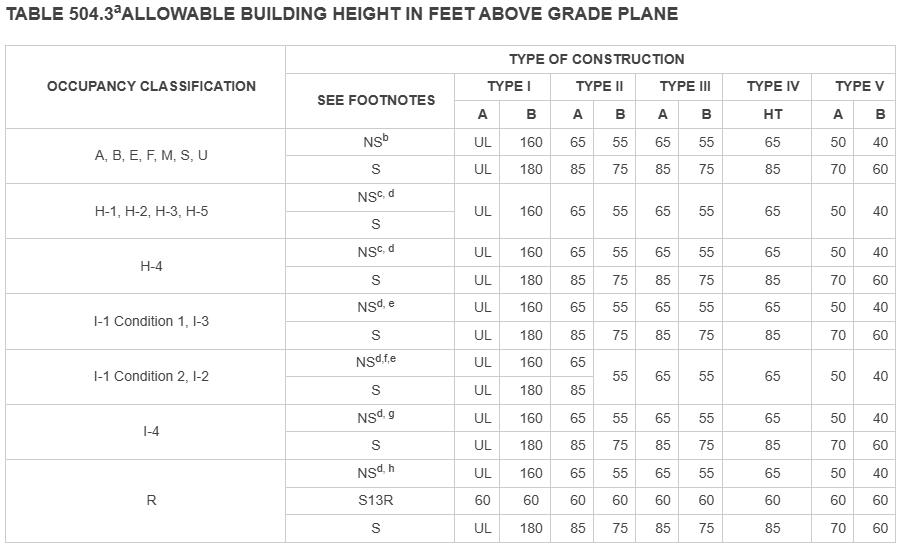
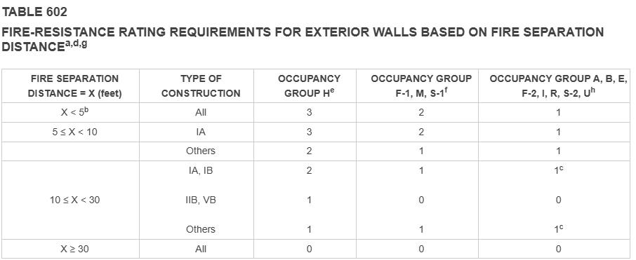
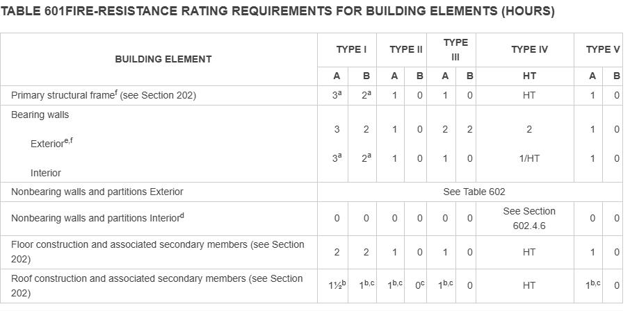
conStruction comPonent ratingS a roof SuPPorterS: fire-reSiStance ratingS of Primary Structural frame and Bearing wallS are Permitted to Be reduced By 1 hour where SuPPorting a roof only. B. excePt i grouP f-1, h,m and S-1 occiPancieS, fire Protection of Structural memBerS Shall not Be reQuired, including Protection of roof framingand decking where every Part of the roof conStruction iS 20 feet or more aBove any floor immediately Below fire-retardant-treated wood memBerS Shall Be allowed to Be uSed for Such unProtected memBerS.
PRELIMINARY SCHEMATIC DESIGN - PART 7
PRELIMINARY SCHEMATIC DESIGN - PART 7
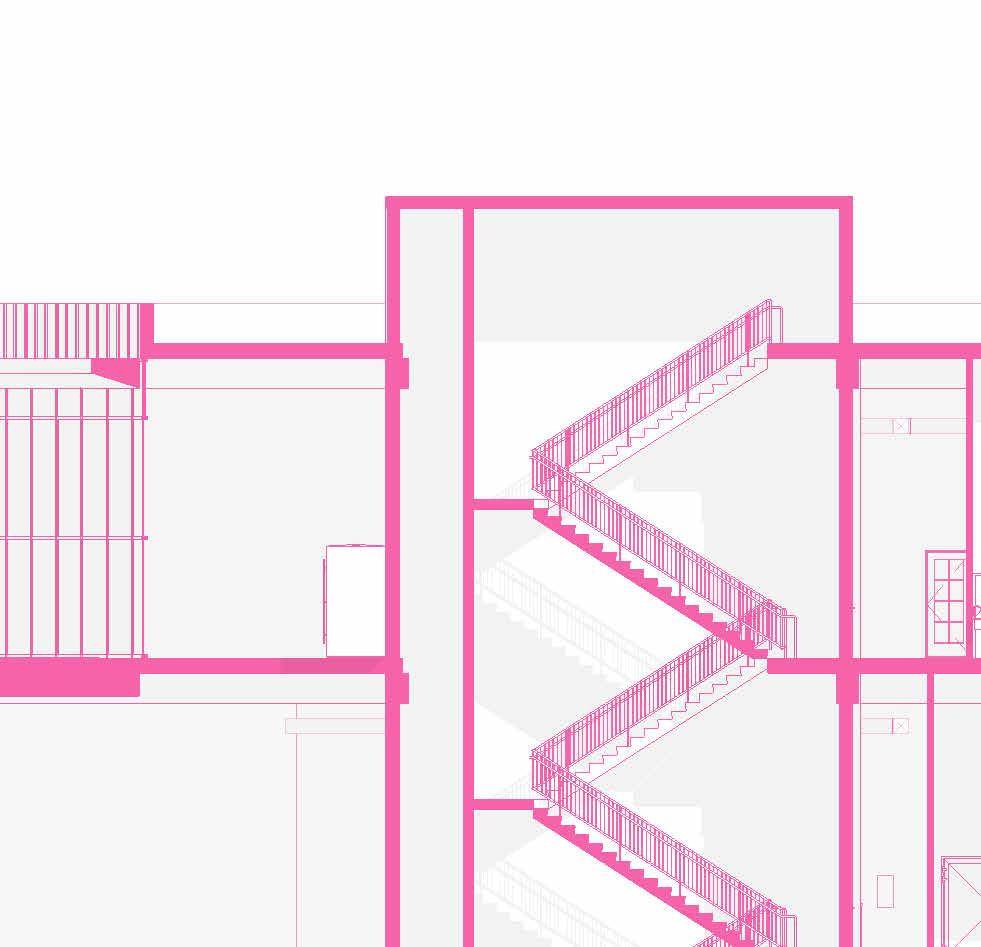
CIRCULATION
PRELIMINARY SCHEMATIC DESIGN - PART 7
PRELIMINARY SCHEMATIC DESIGN - PART 7
nS Section
1’=20”
we Section
PRELIMINARY SCHEMATIC DESIGN - PART 7
PRELIMINARY SCHEMATIC DESIGN - PART 7


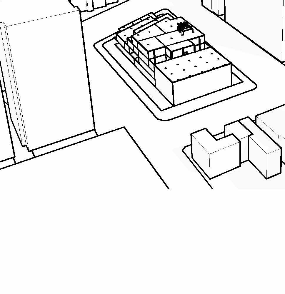
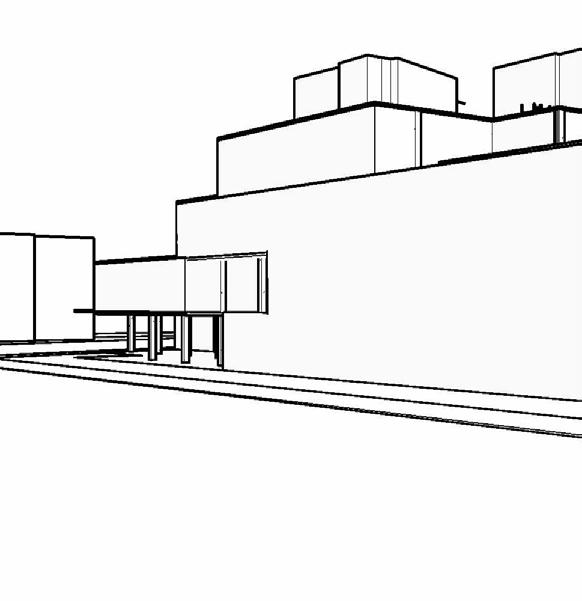
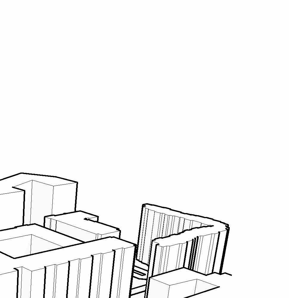
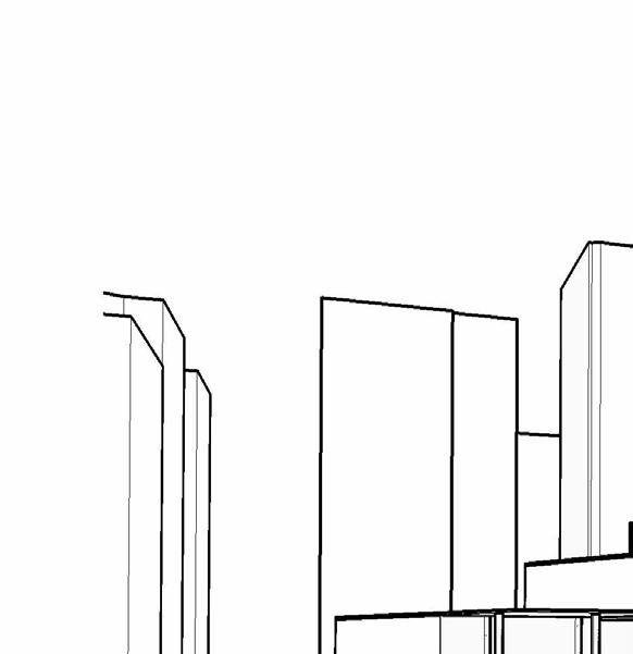


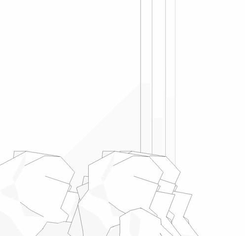
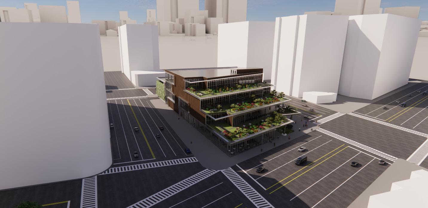
nw ariel
Sw ariel
ny ave Street view
STRUCTURAL SYSTEMS - PART 8A
STRUCTURAL SYSTEMS - PART 8A


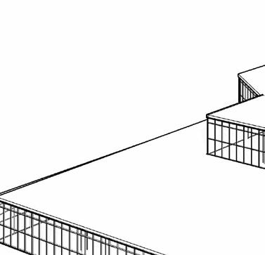
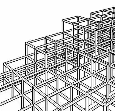
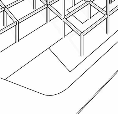

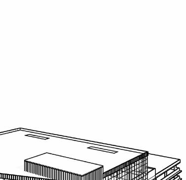
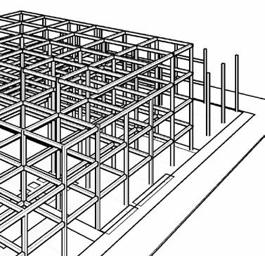


core SyStemS
column SyStemS
Structural framing SyStemS
floor SyStemS
encloSure SyStemS
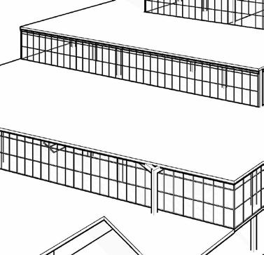
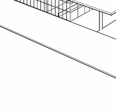
ENCLOSURE SYSTEMS - PART 8B
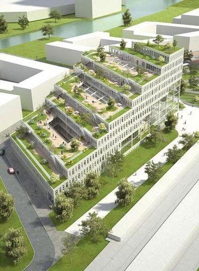
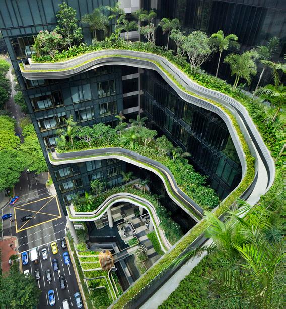
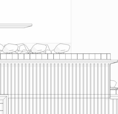
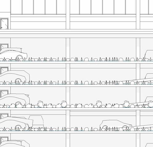
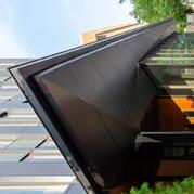
interactive green BalconieS - the StePPing language of the wellneSS center allowS for interactive green SPaceS, merging outdoor and indoor SPaceS
green wall - the encloSure of the Parking garage will uSe a different But communicative language to the encloSure SyStemS in the wellneSS center
vertical wood elementS - the current Building form takeS a longitudinal orientation; the exPreSSion of vertical wood elementS and green infraStructure iS a communicative deSign

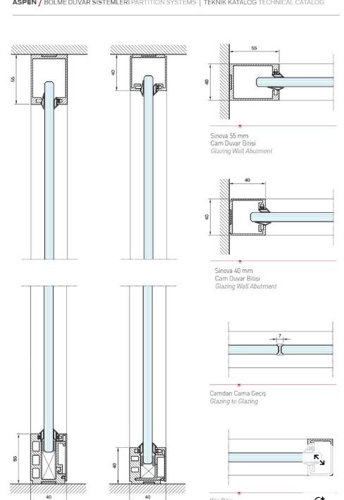
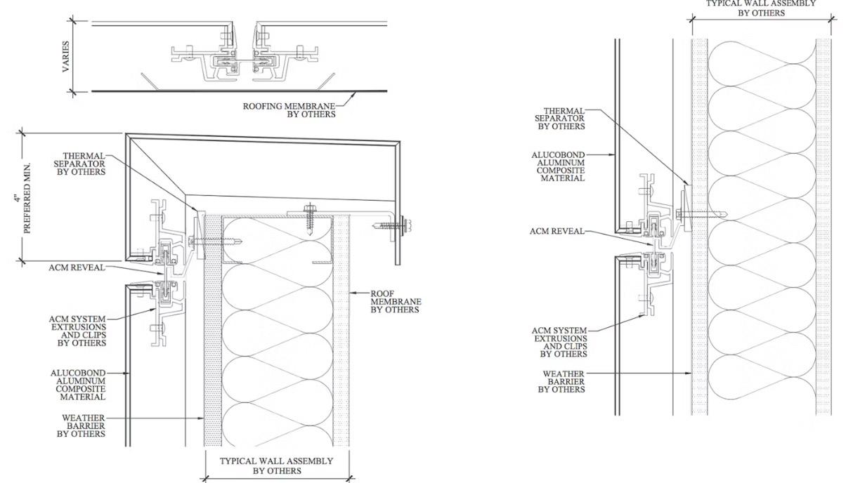
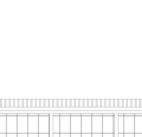
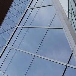
curtain wall SyStemS - inSulated temPered glaSS curtain wall with caP Bead jointS to make glazing water tight and weathertight for faceSealed glazing SyStemS
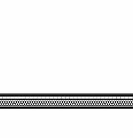
MECHANICAL SYSTEMS - PART 8C
DRAINAGE
GREEN ROOF
GREEN SYSTEMS -
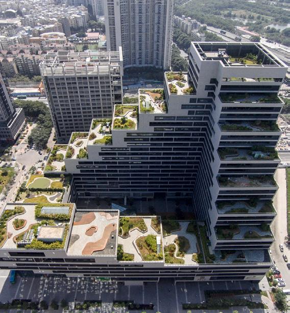
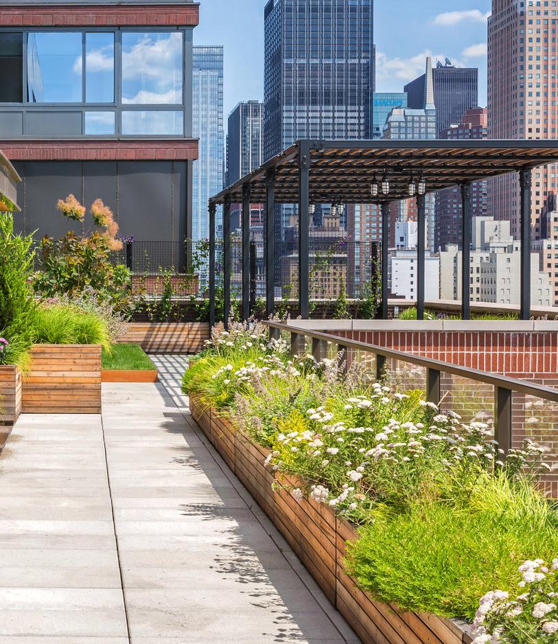
Roof Terraces
The roof space of a commercial building is not only functional in housing mechanical systems and improving energy efficiency, but it can also serve as an aesthetic feature, recreational area, or an extension of usable space. The role of roof space in commercial buildings continues to expand, offering diverse uses and opportunities.
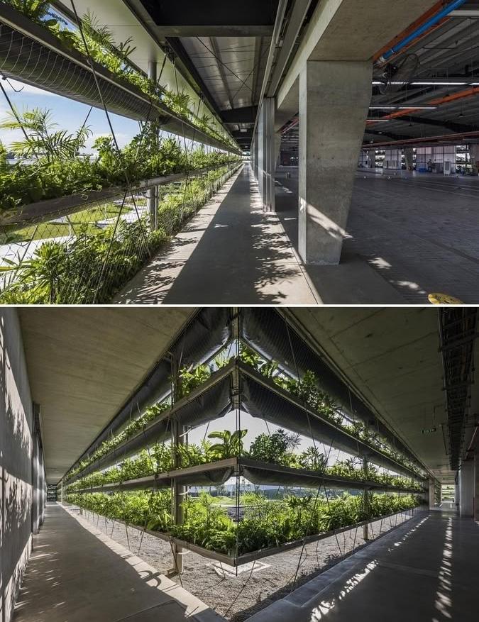
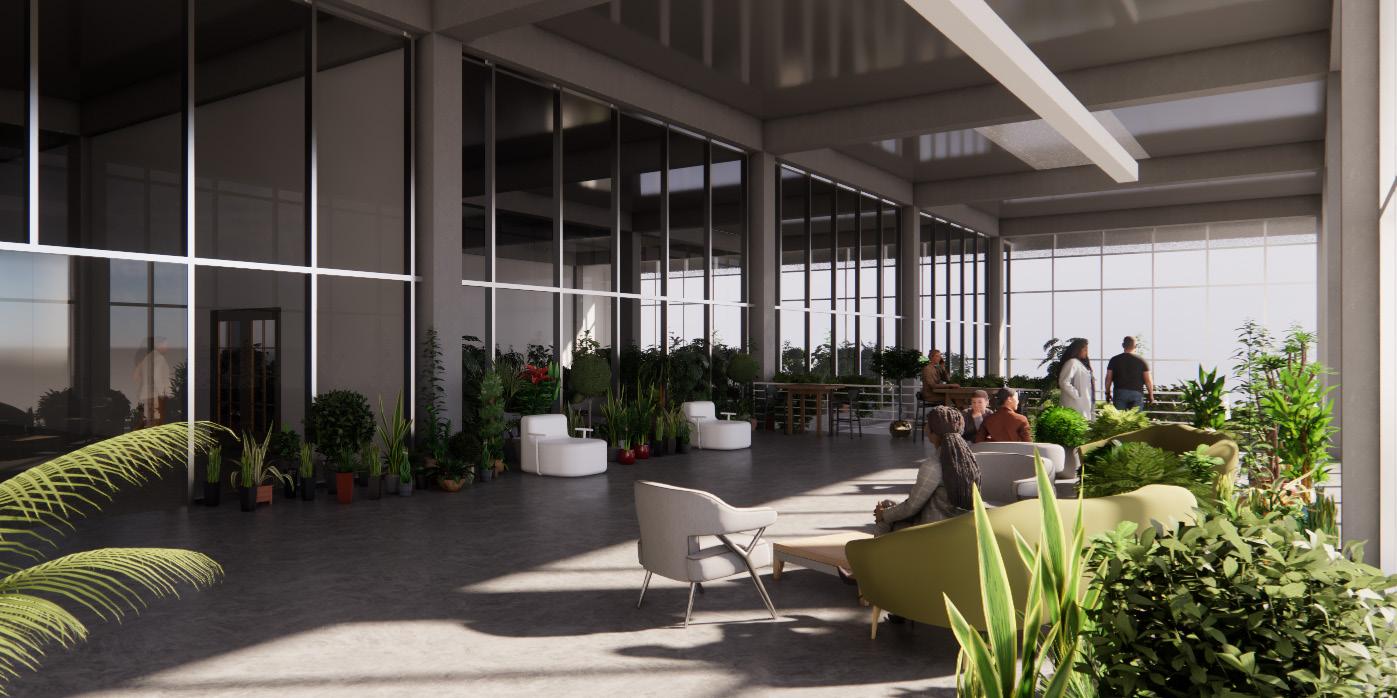
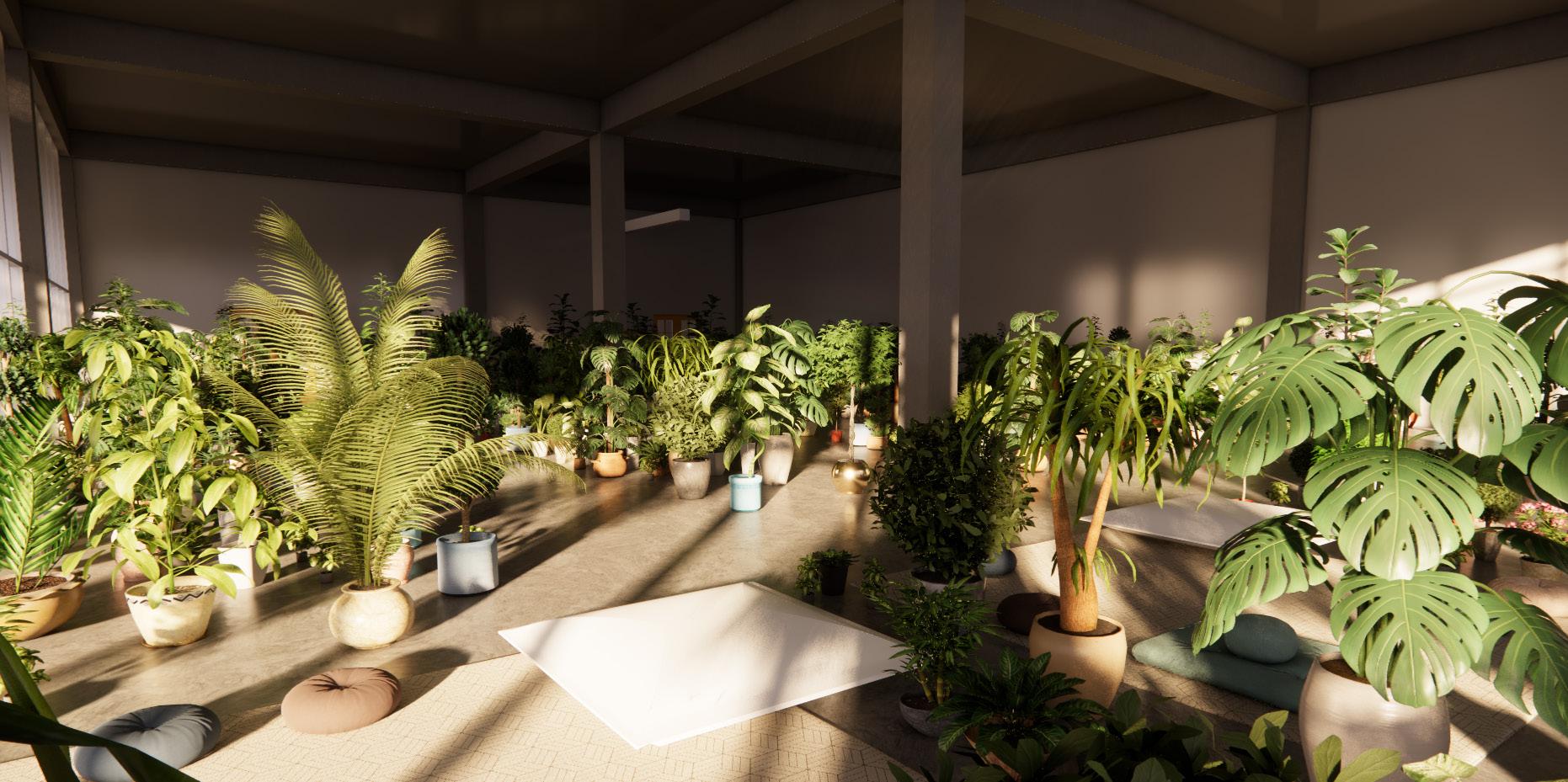
Botanical Lounge
A plant room or indoor garden enhances well-being by reducing stress, improving mood, and increasing mental clarity. Plants purify the air, boost relaxation, and encourage mindfulness.
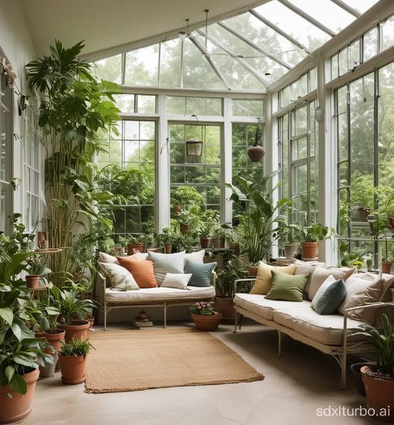
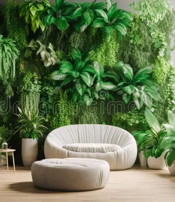
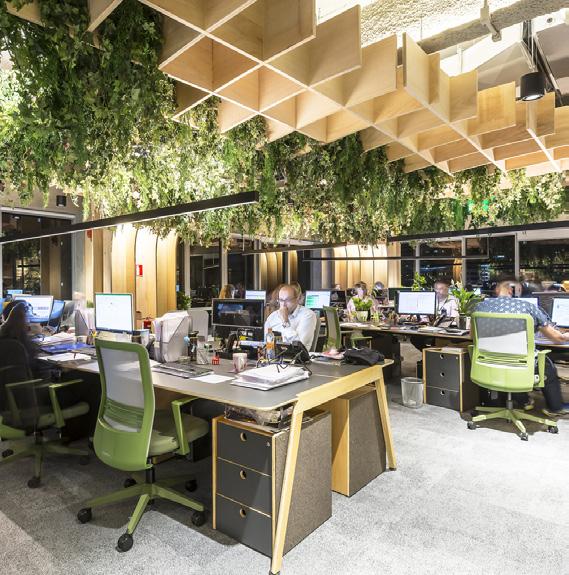
Biophilia
Incorporating biophilia into the interior of a wellness center enhances physical, mental, and emotional well-being, creating an environment that promotes relaxation, healing, and rejuvenation. Biophilic Design supports sustainability and fosters a deep connection to nature, making it a powerful tool for promoting holistic well-being within a wellness center.

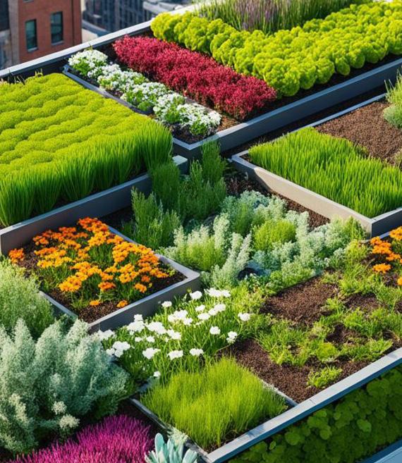
Green Roofs
Green roofs improve air quality, reduce urban heat, manage stormwater, and support biodiversity. They lower energy costs, extend roof lifespan. Emotionally, they reduce stress, boost productivity, and create social spaces. Overall, they enhance sustainability and urban well-being.


SCHEMATIC DESIGN - PART 9 FLOORPLANS
SCHEMATIC DESIGN - PART 9 FLOORPLANS
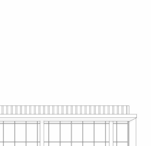
SCHEMATIC DESIGN - PART 9
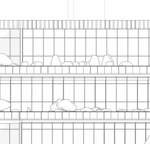
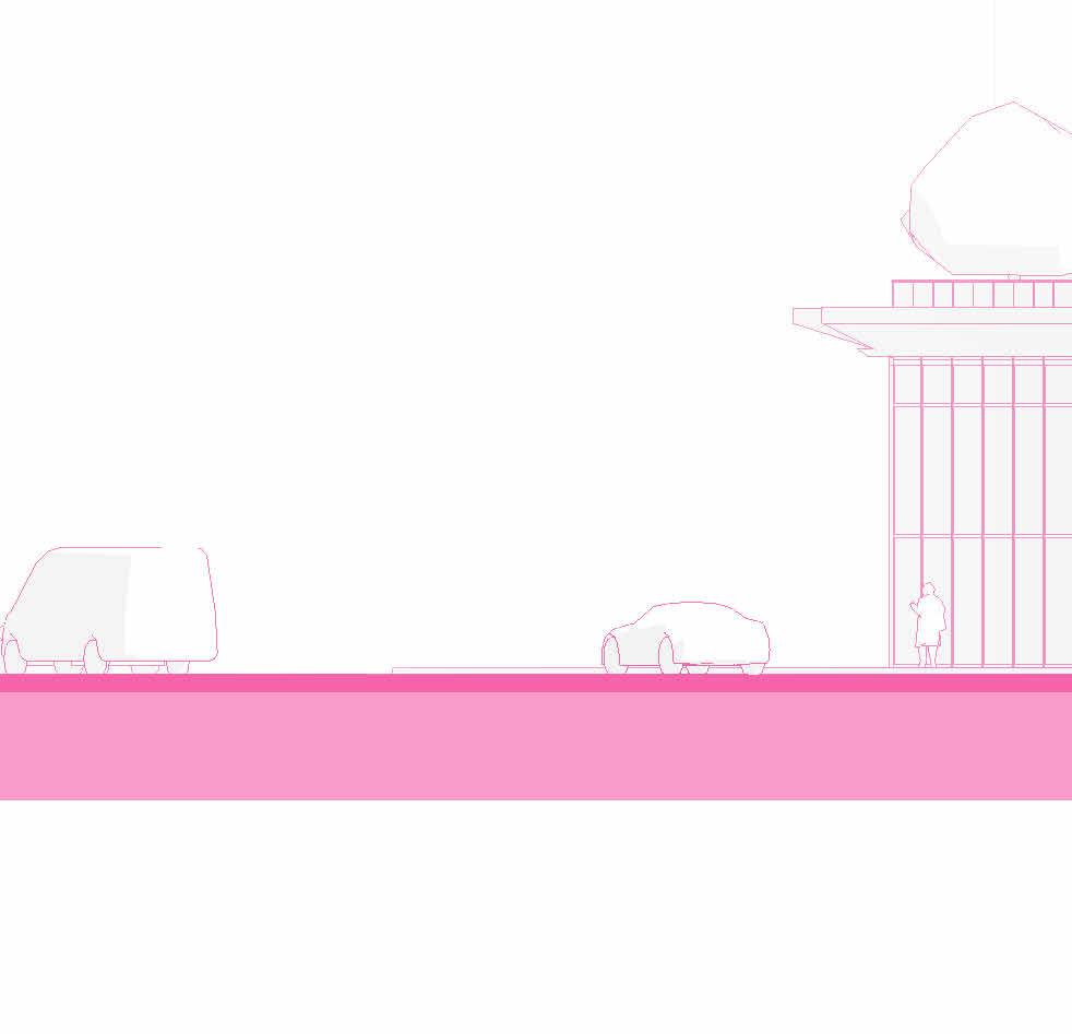
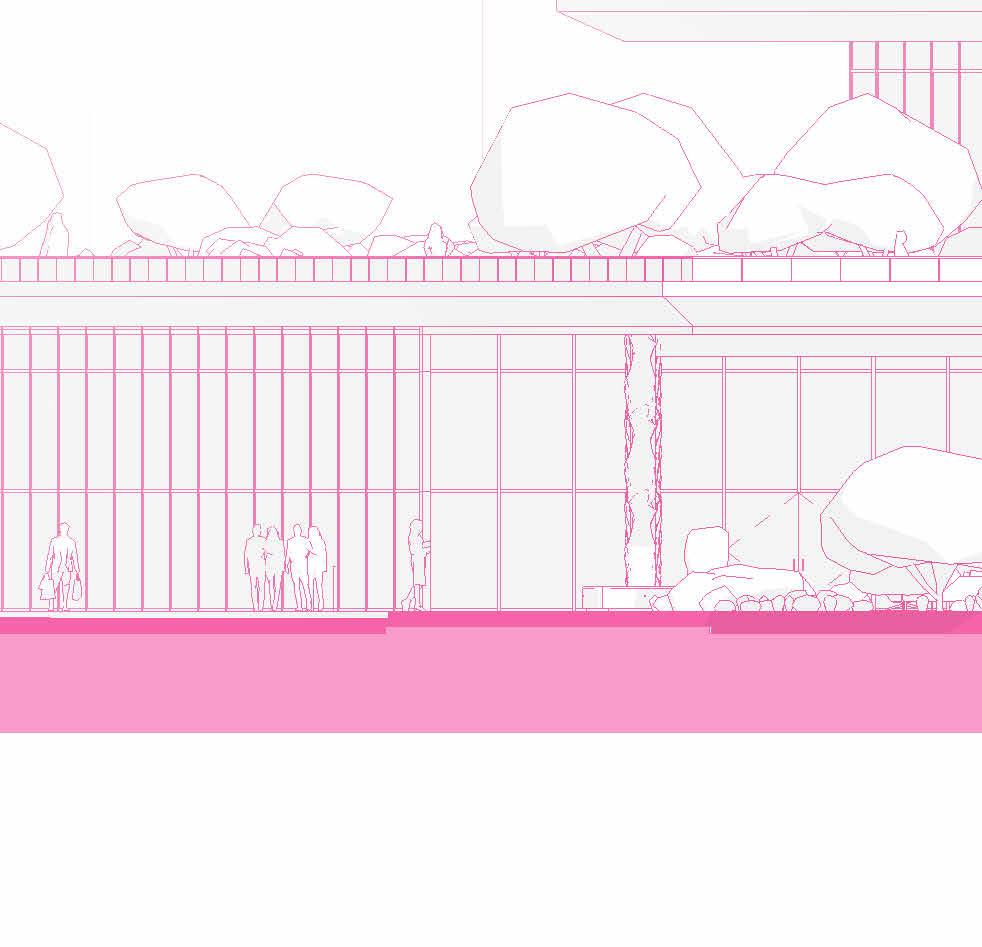
ELEVATIONS


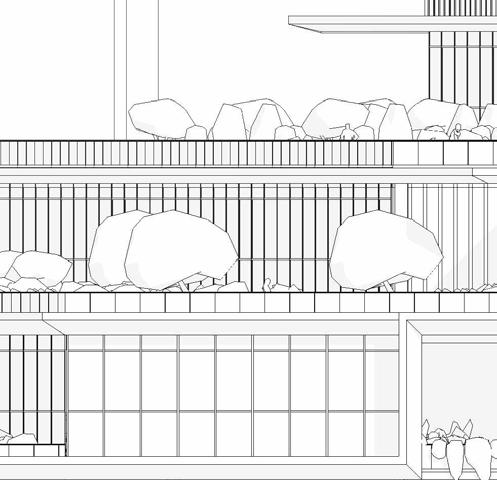

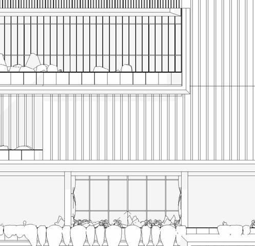

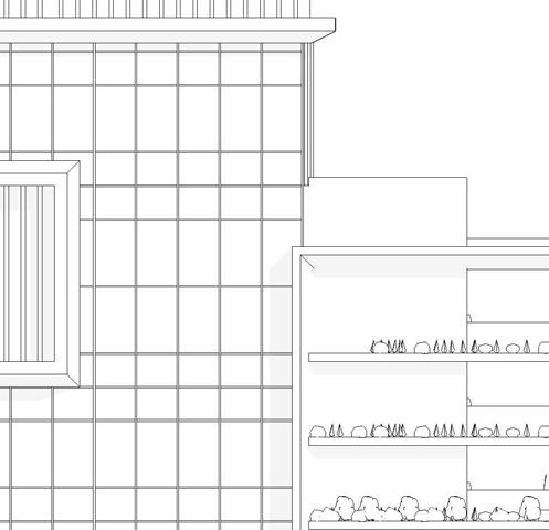


SCHEMATIC DESIGN - PART 9
ELEVATIONS


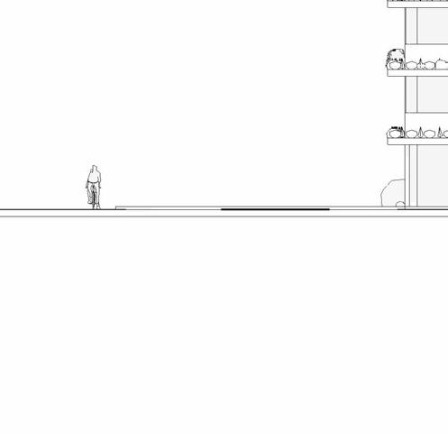


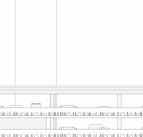


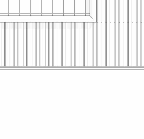


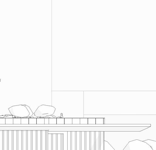
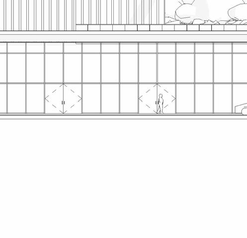


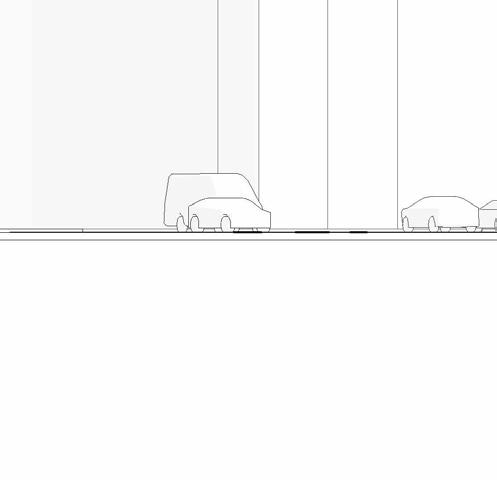
eaSt elevation
= 20’-0”
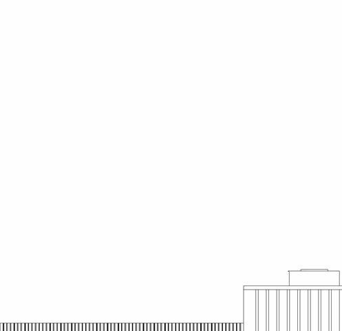
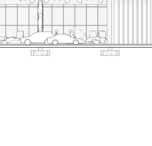
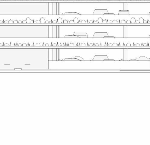
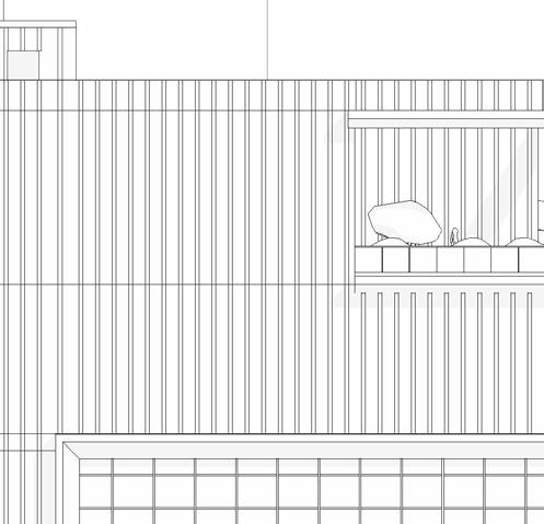
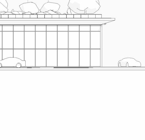
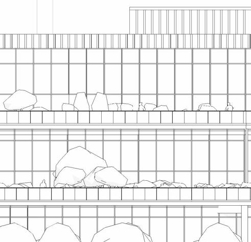
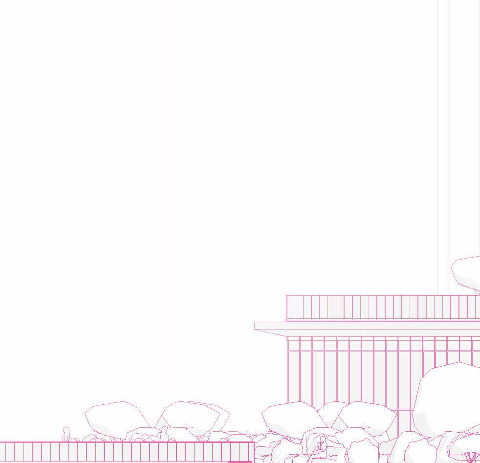
SCHEMATIC DESIGN - PART 9
ELEVATIONS


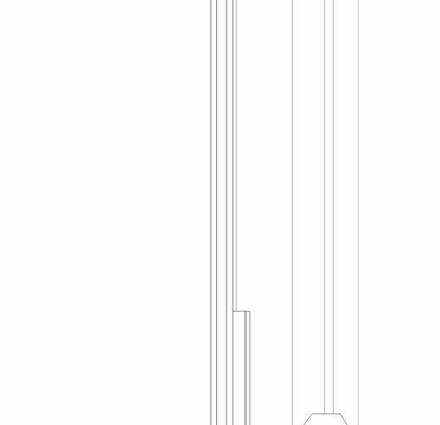


South elevation
1”=20’-0”
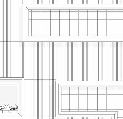
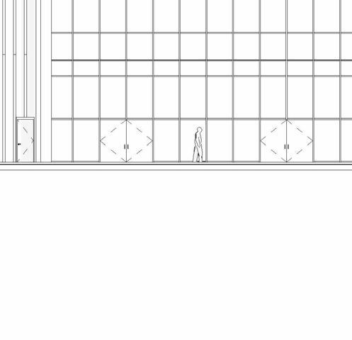
SCHEMATIC DESIGN - PART 9
ELEVATIONS


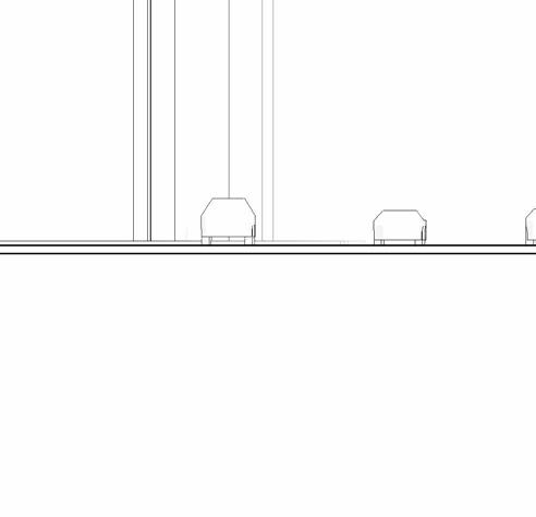

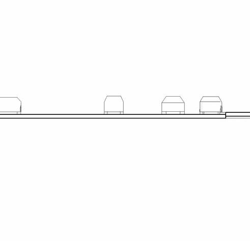


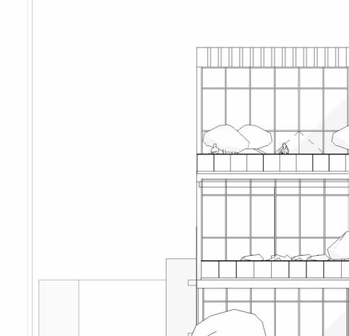
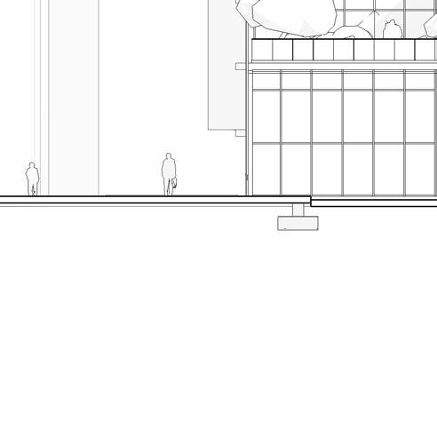


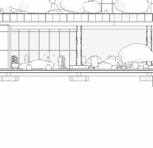

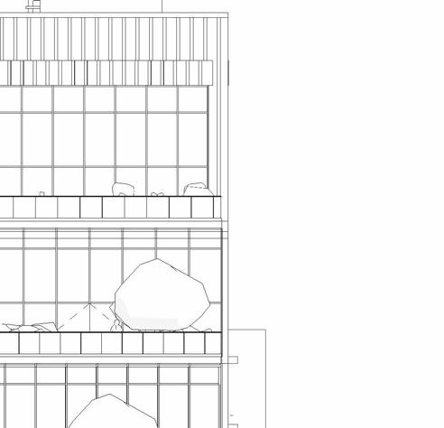
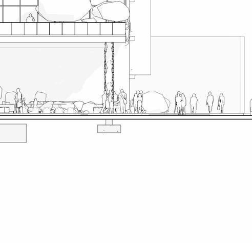


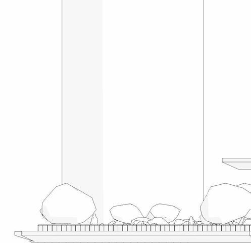
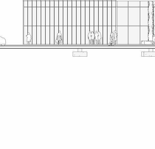
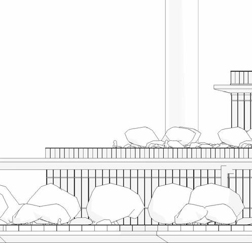
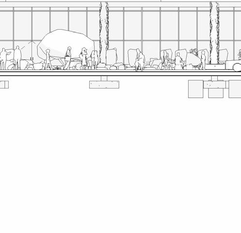
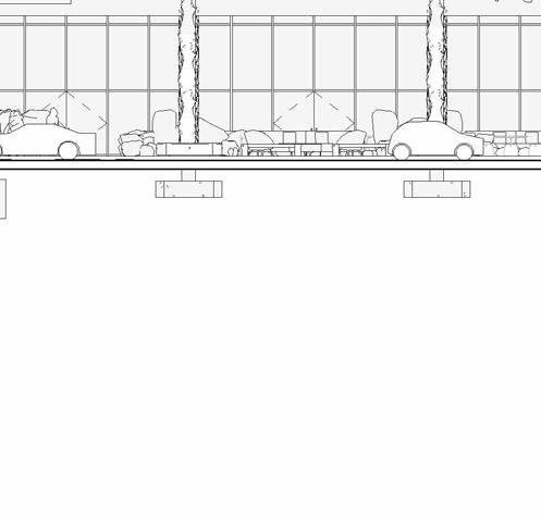
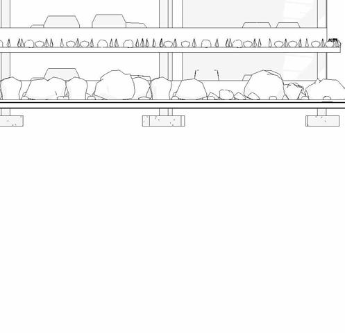
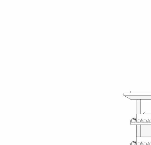
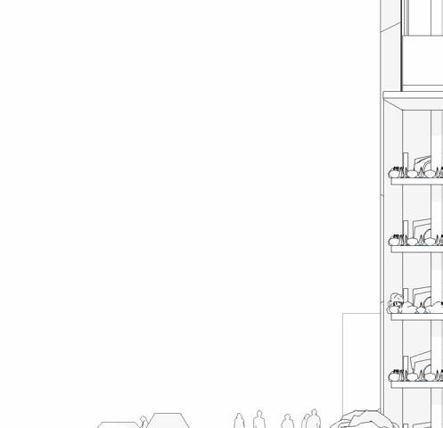
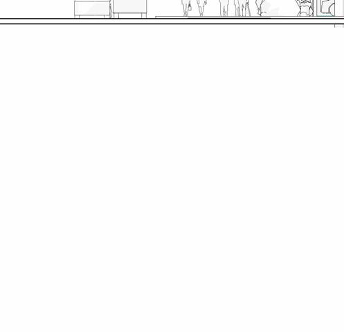
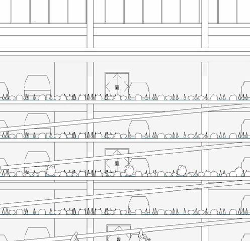
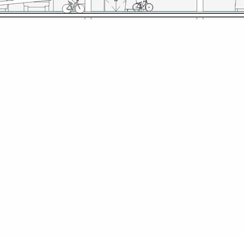
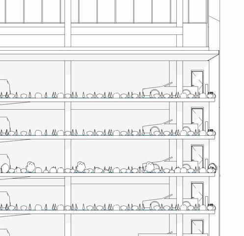
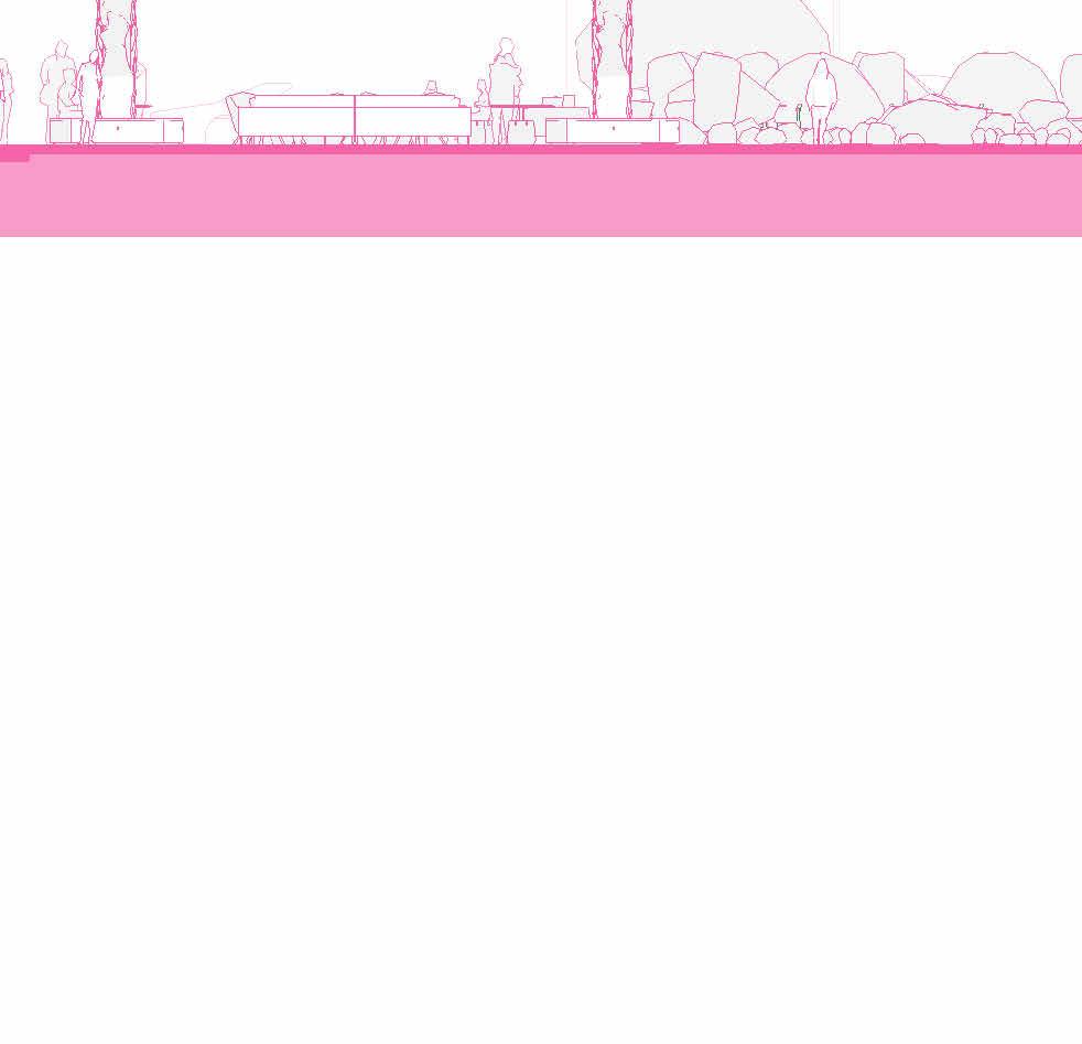
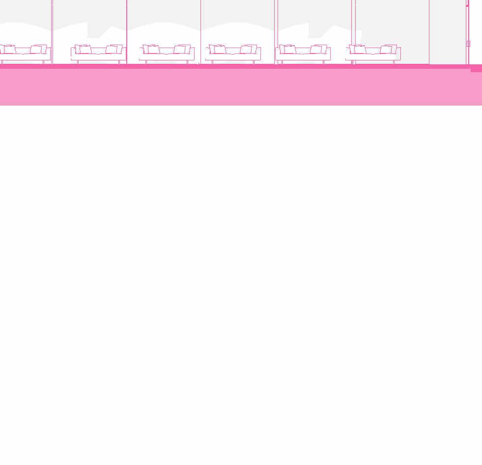
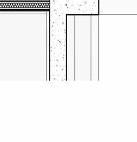
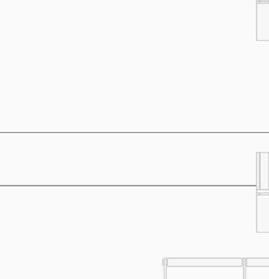
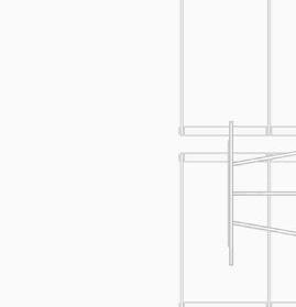
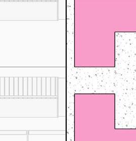
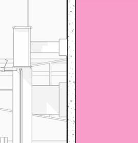
SCHEMATIC DESIGN - PART 9
SECTIONS


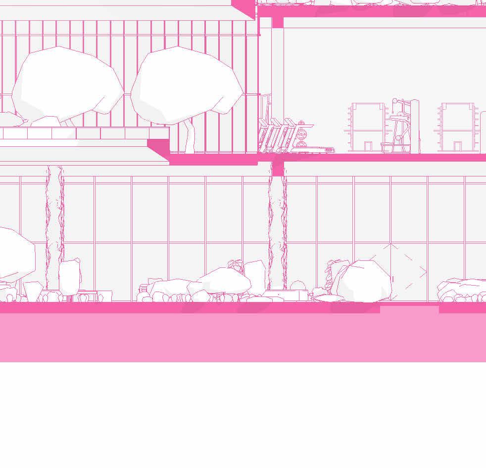

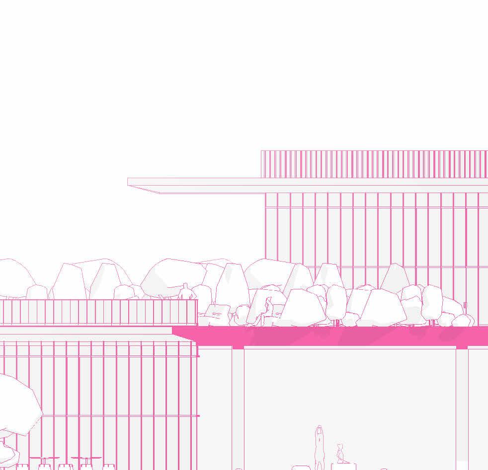
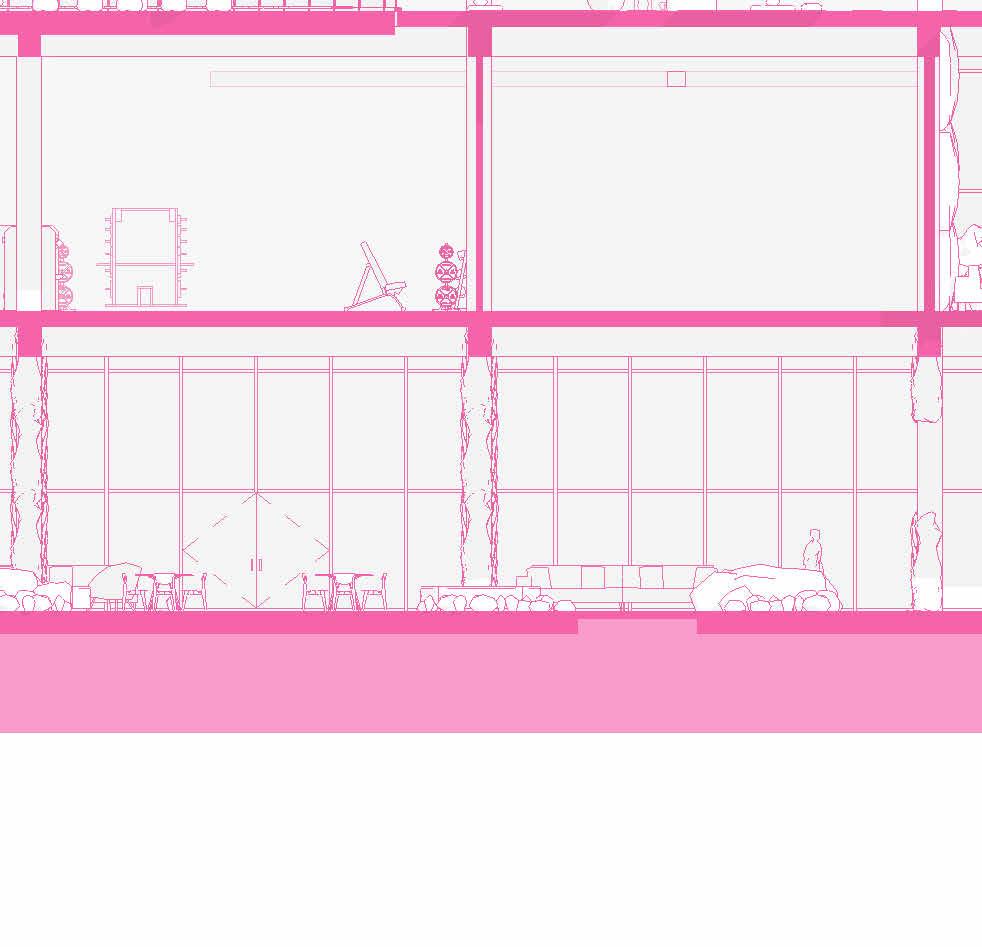


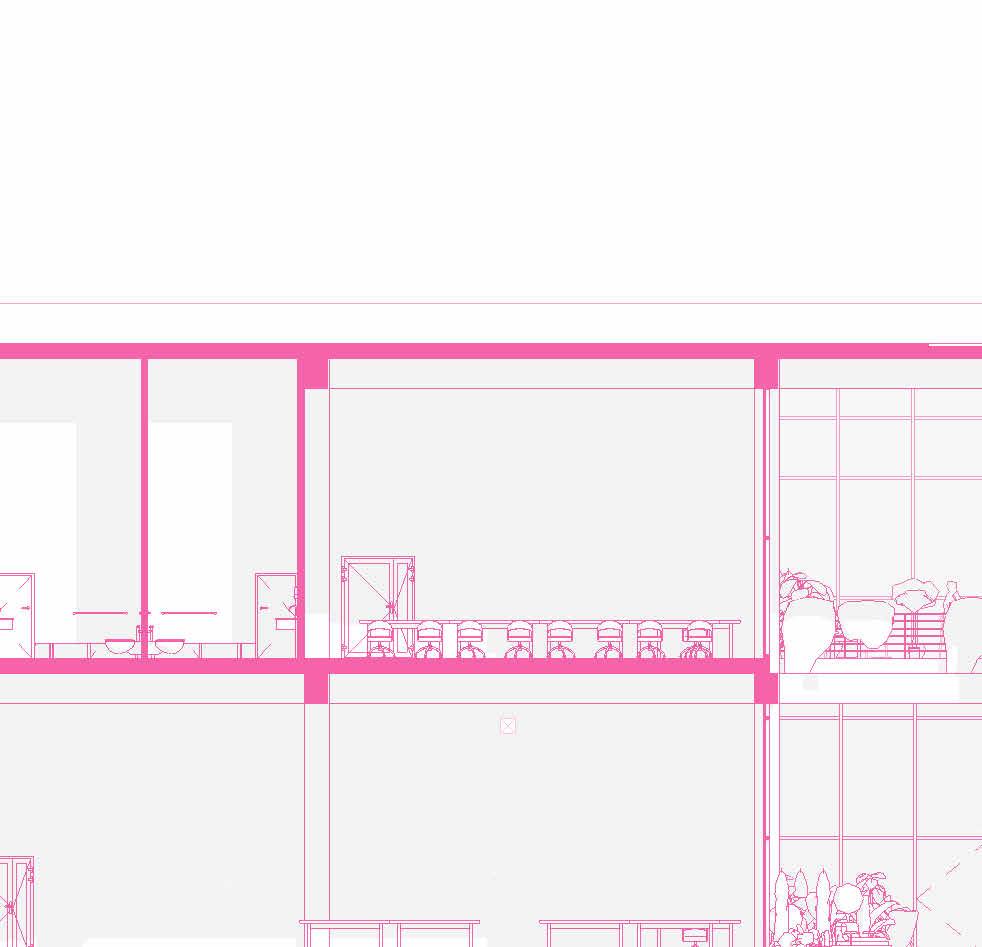
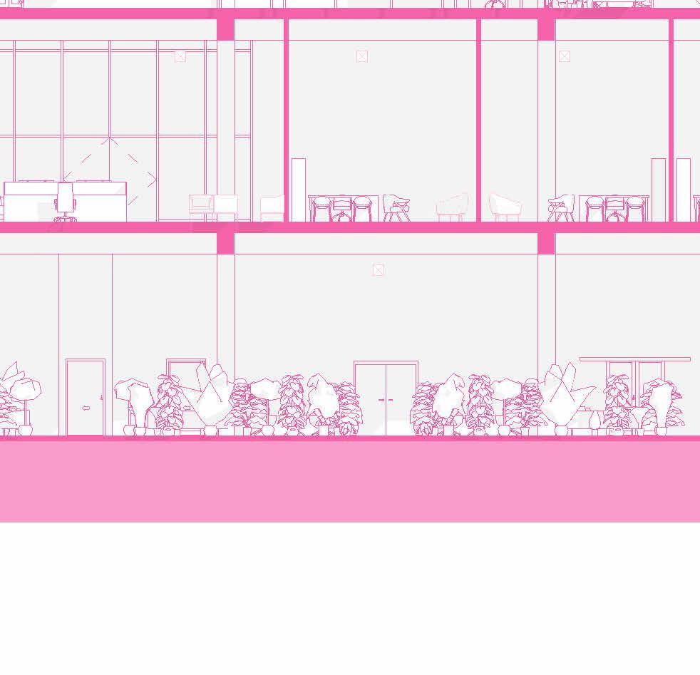
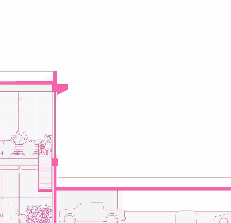
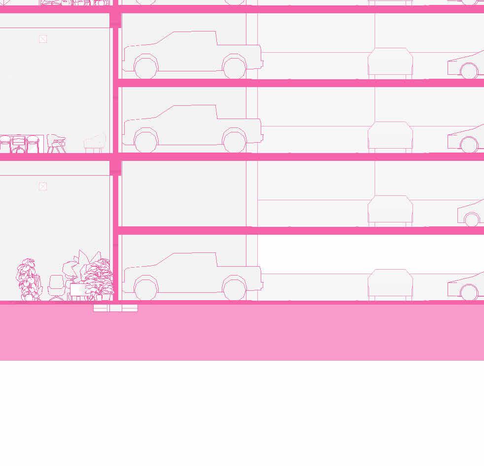

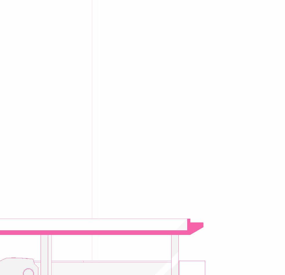
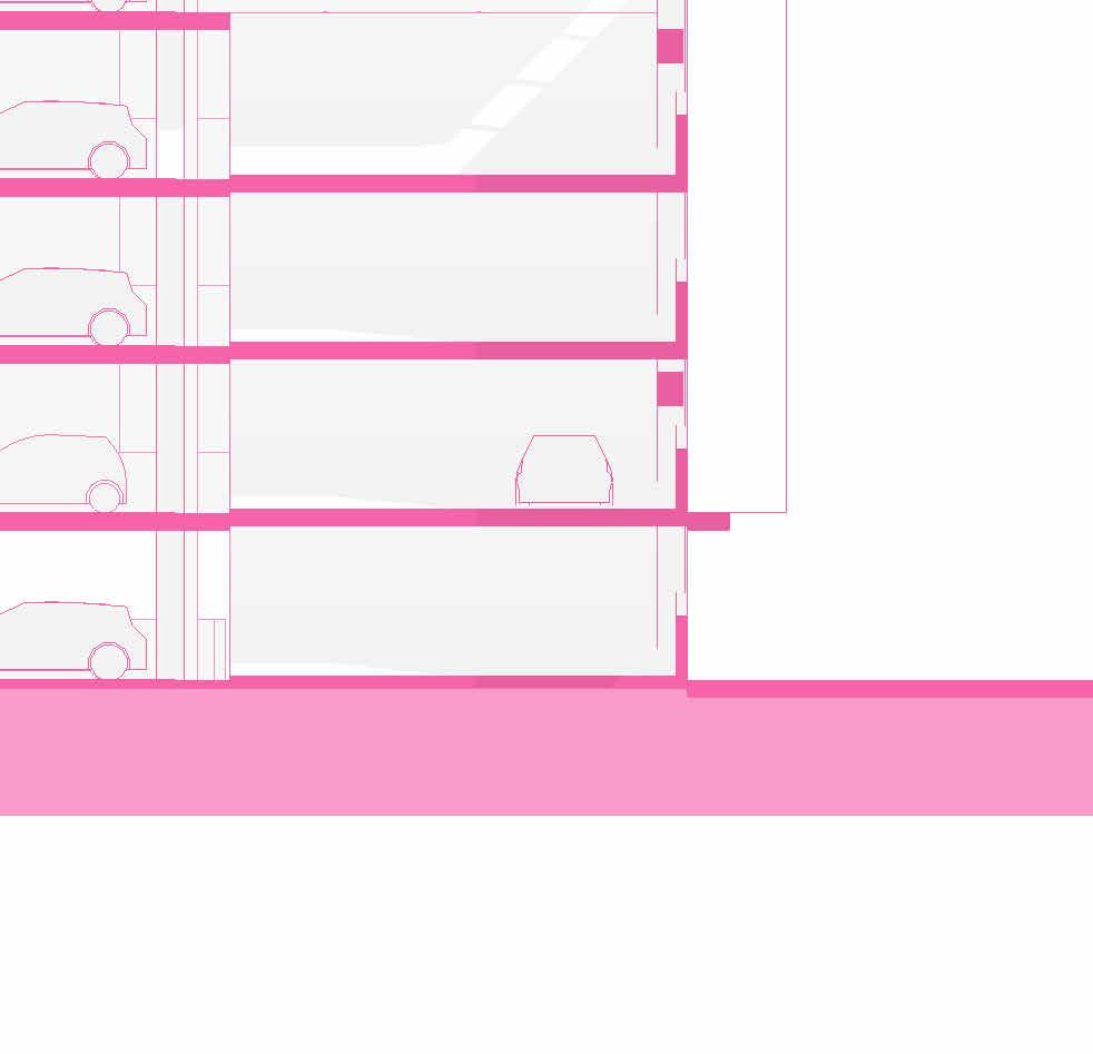

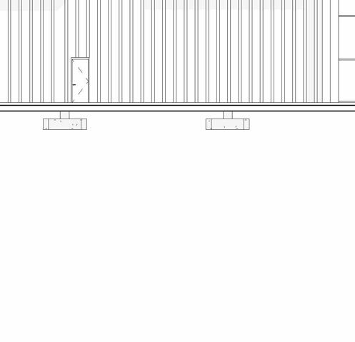
SCHEMATIC DESIGN - PART 9
SECTIONS
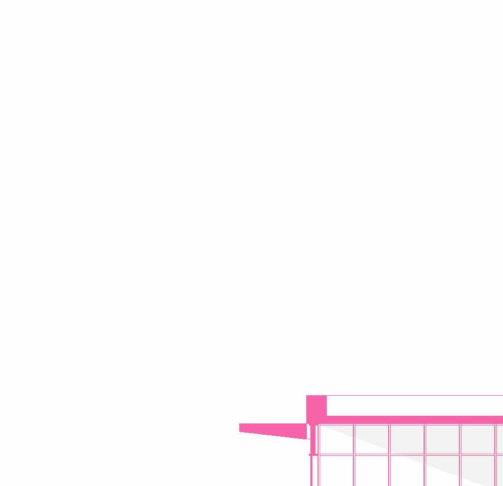

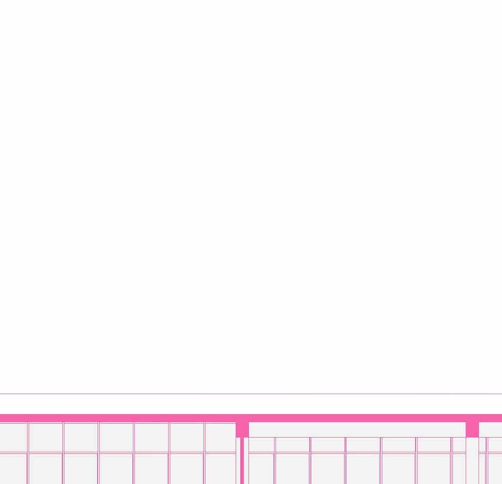
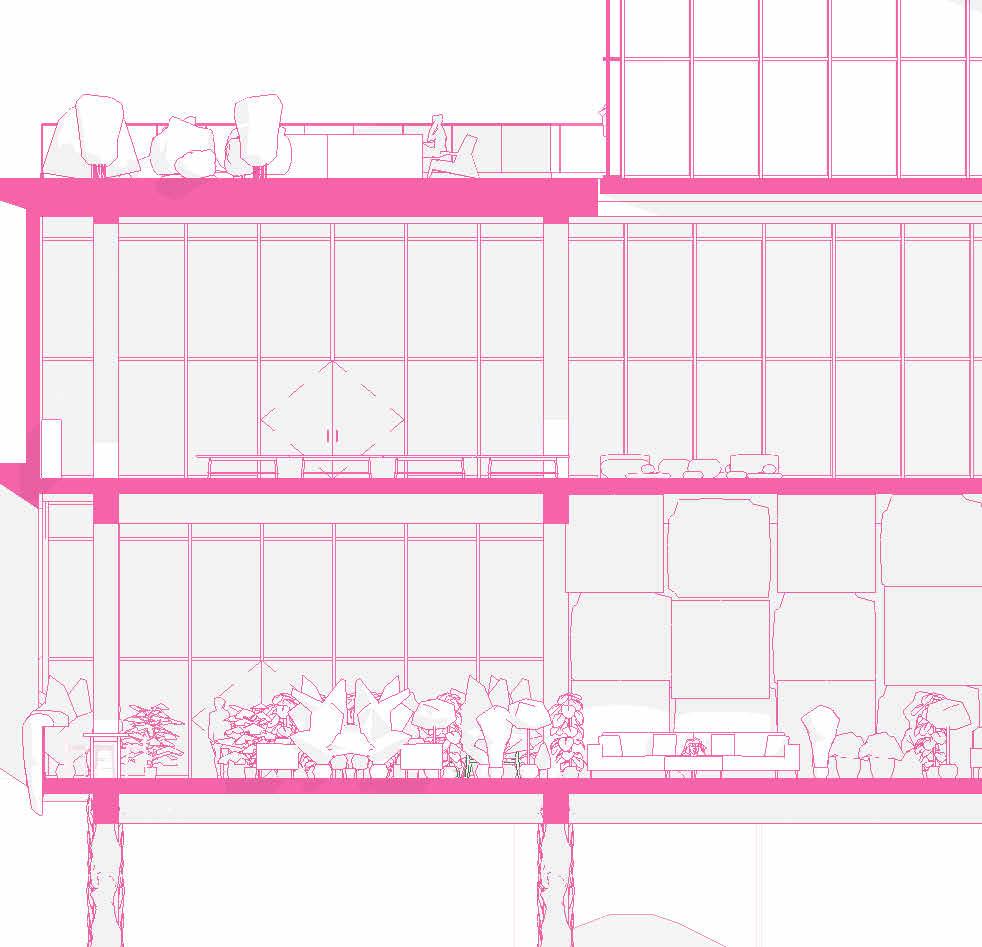
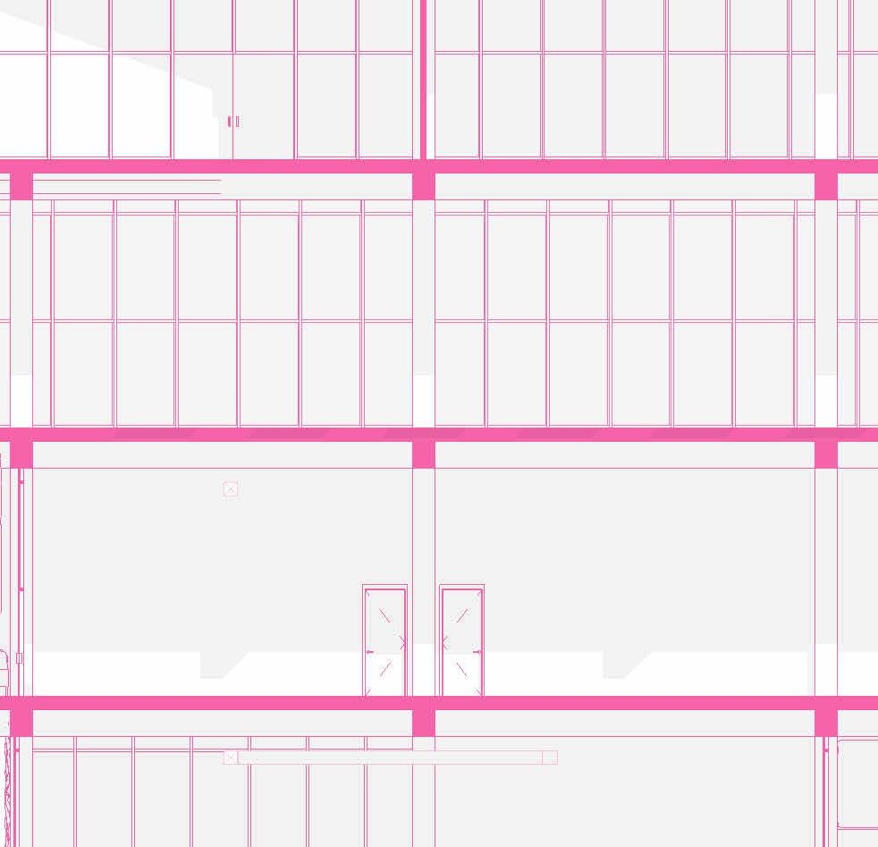

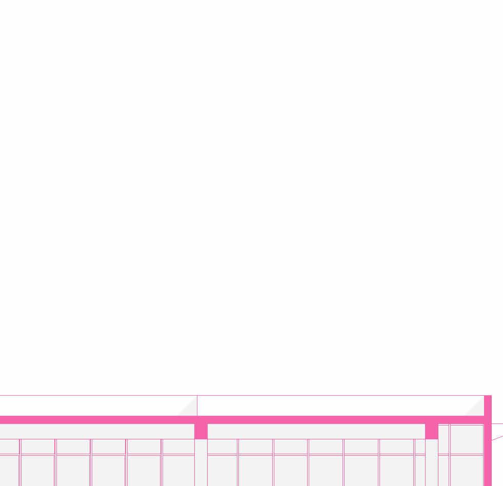
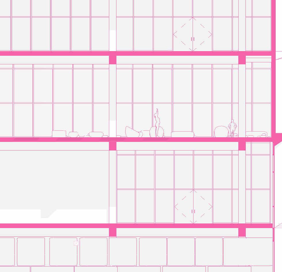


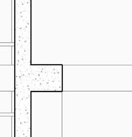
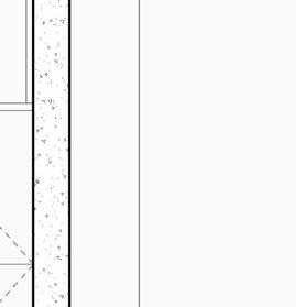
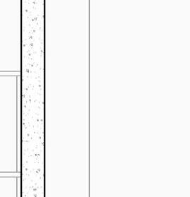
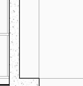
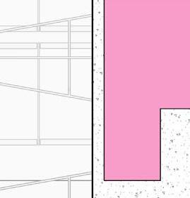
tranSverSe Section 1” = 20’-0”


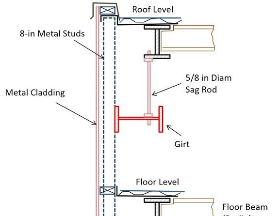
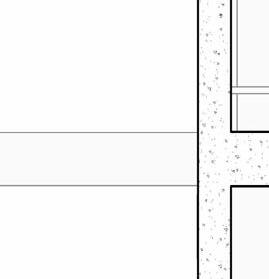
2” a ir g a P 2” r 6” m S 6” B att n S ulation 5/8” g B w d c P B w B e S P enn S lavania S edge


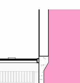
12” S tructural c oncrete S la 10” ightweight g rowing edium g r
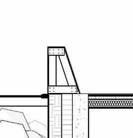
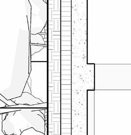
t ile t ech c ool r oof P aver S
1.5” S B 2” g B 3/16” o t P f f 8” rainage oldroydxv 20 greenxtra 0.16”
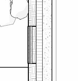
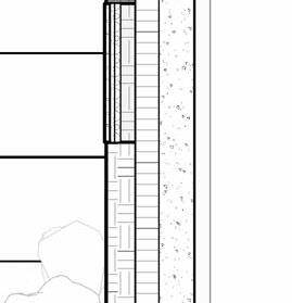

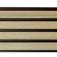
2” S lat S olution w ood S lat P anel


12” c S 20” x 20” c a S t i n P lace c c
hallow f oundation #6 r einforcing S teel e ach w ay 6” c oncrete S la B on g rade a m 20” x 20” c a t n P lace c oncrete c loumn 18” 24” c P c oncrete B eam 20” 24” c P c B e t g 6” m etal S tud a luminum trim S f k r m r oof d en S e g la SS S heeting S lo o P a Q ue S P nadrel P anel
3 5/8” m etal S tud g y PS um B oard


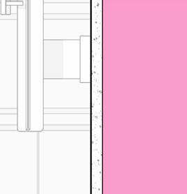
8’ x 8’ c oncrete c olumn P ad g B 36” x 96” S ingle f lu S h d oor
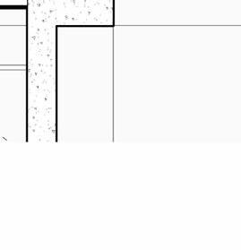

#6 r einforcing S teel e ach w ay e levation 3/8” = 1’-0” e xterior t em P ered n S ulated g la SS g la SS d oor 5/8” g y PS um B oard 3 5/8” m etal S tud 5/8” g B c d S e Q c heckout c ounter

20” 20” c i P c c e nlarged f loor P lan 3/8” = 1’-0”
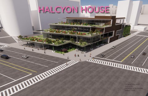
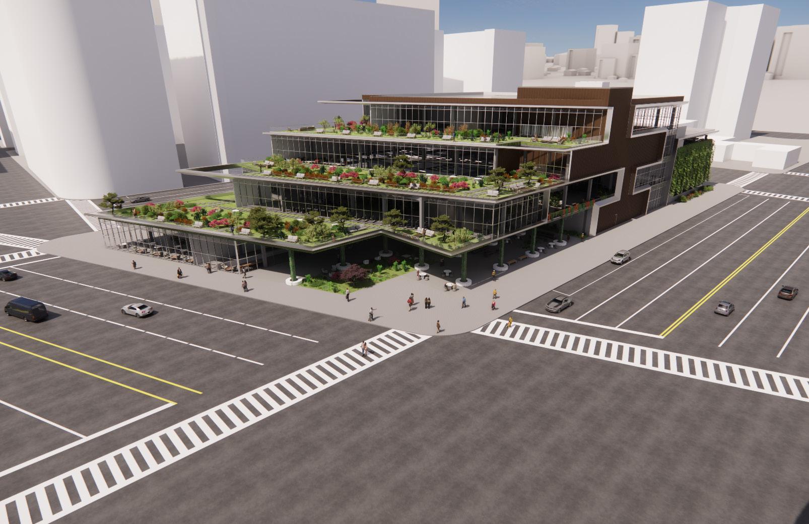
HALCYON HOUSE
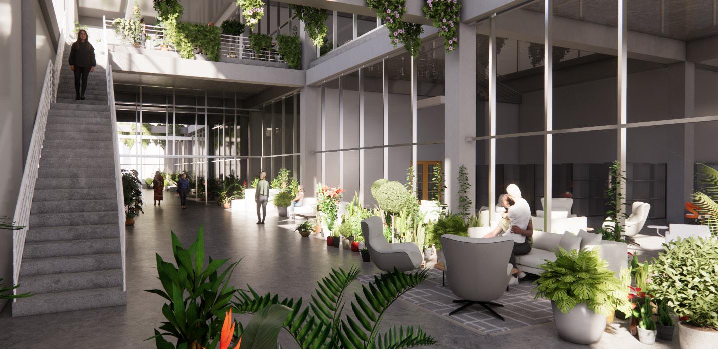

Botanical lounge lv3
relaxation Studio
Botanical lounge lv4
exerciSe Studio
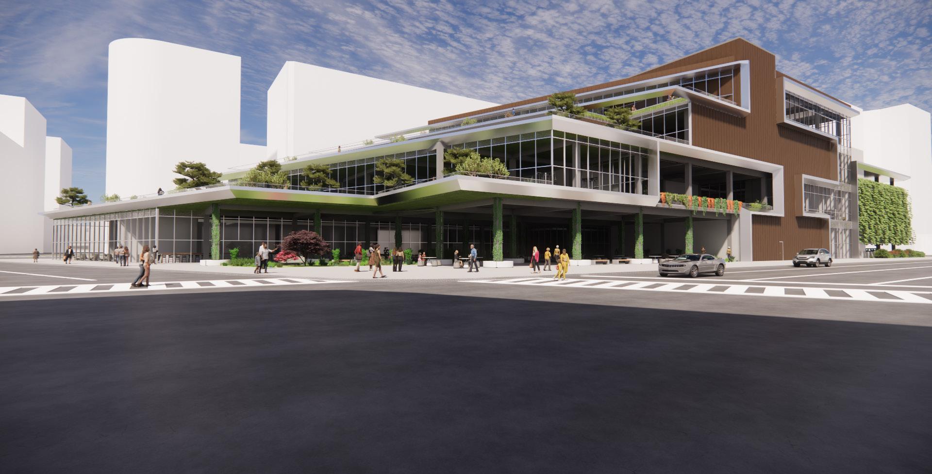
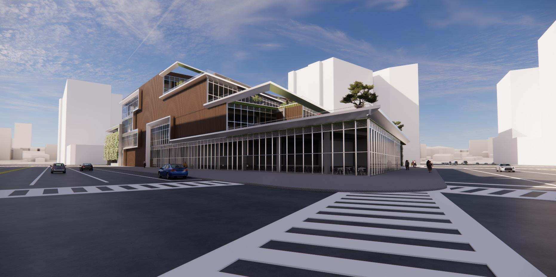

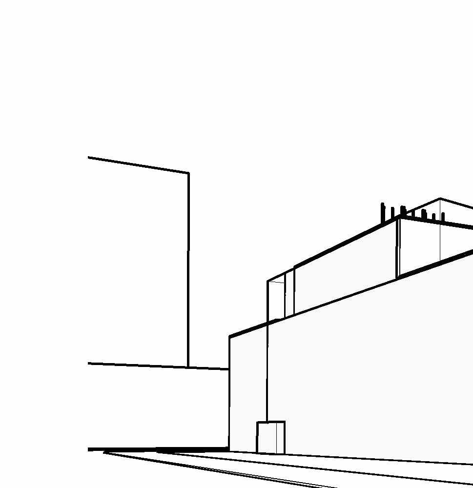
new york ave Street view eaSt eye level view
ny ave aerial view
terrace view lv 2
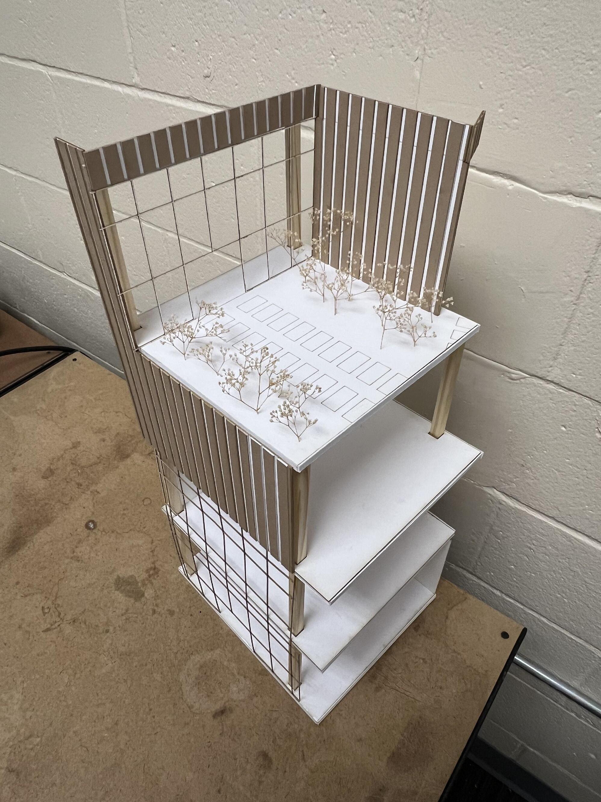
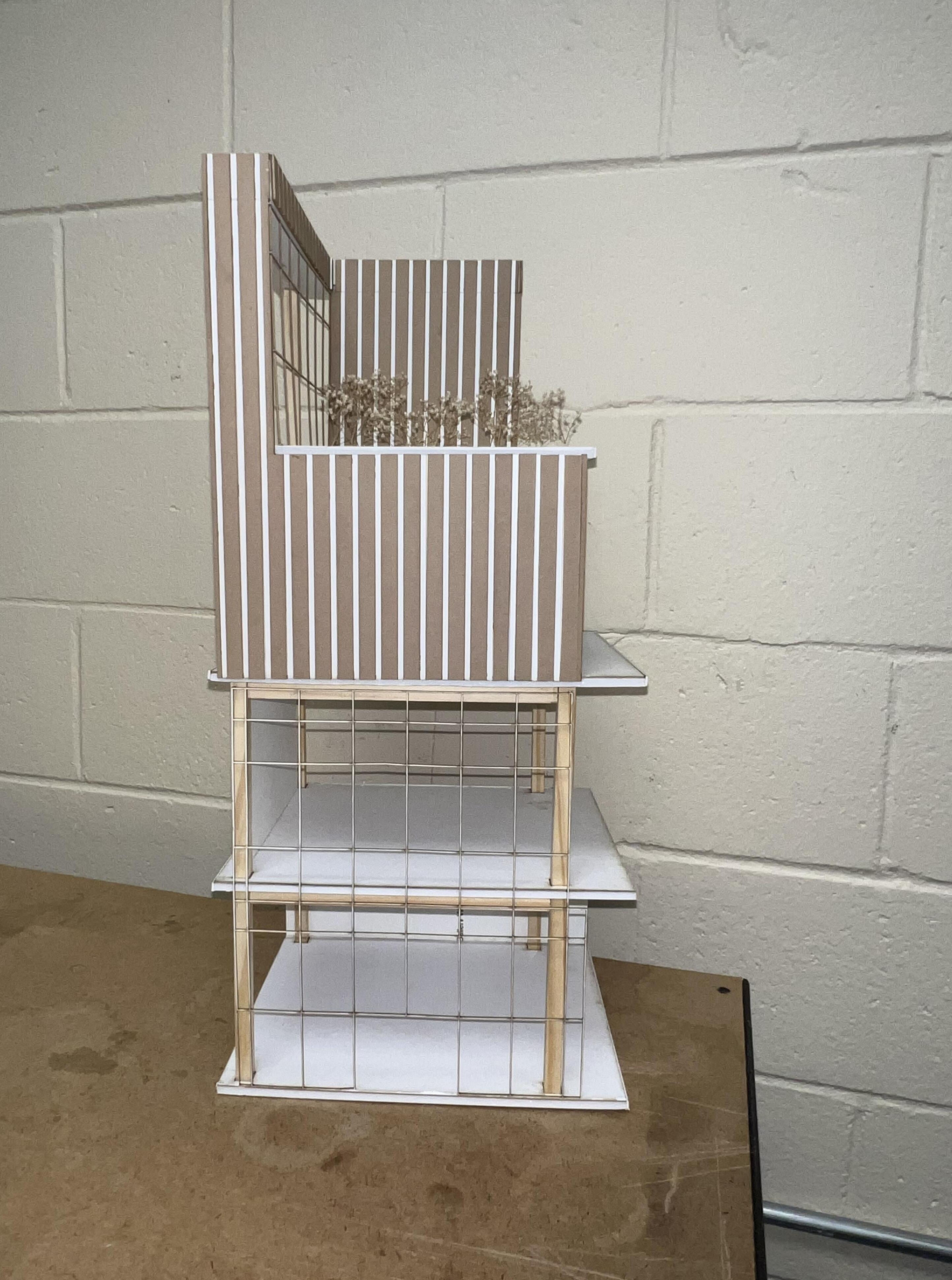
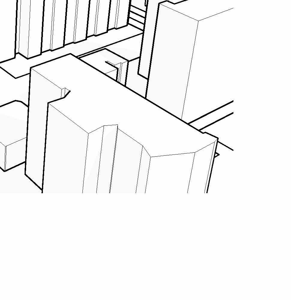
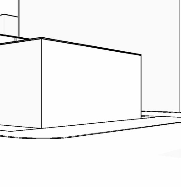
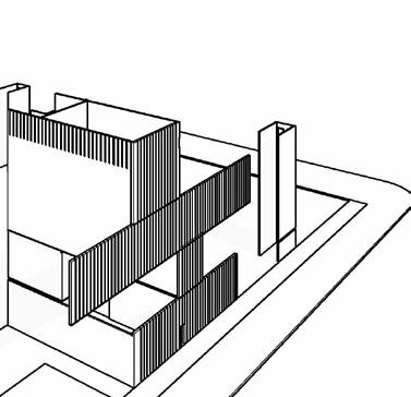
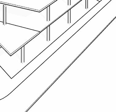
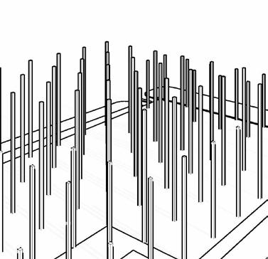
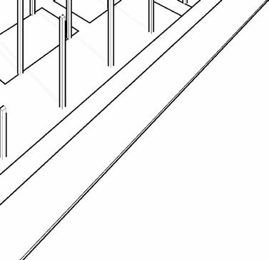
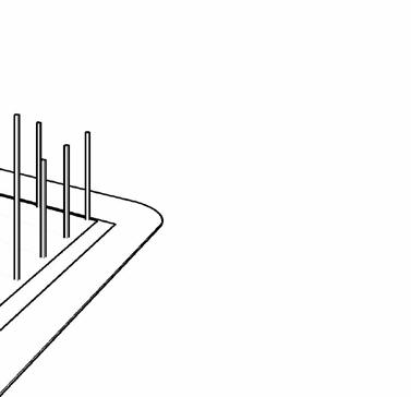
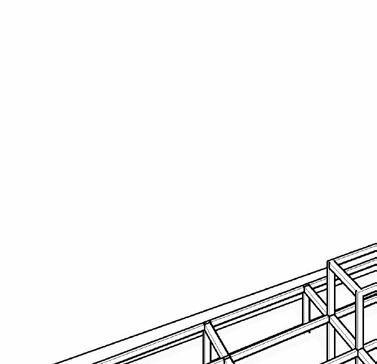
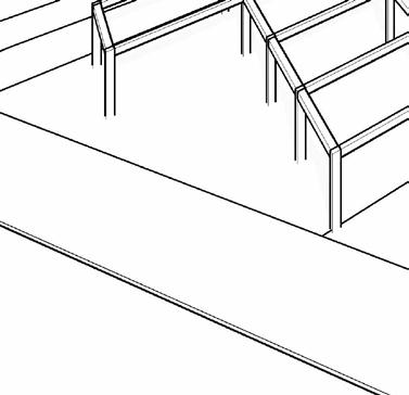
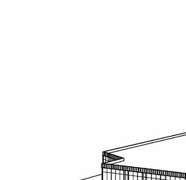
FINAL PHYSICAL MODEL - PART 13
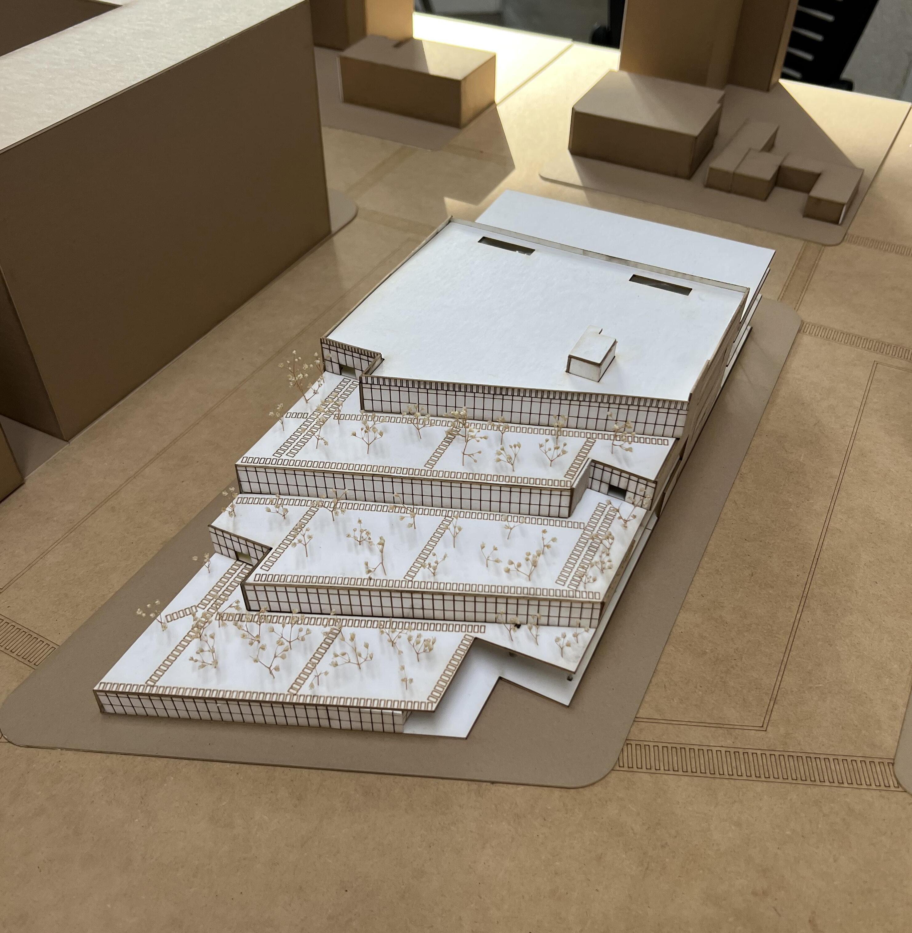
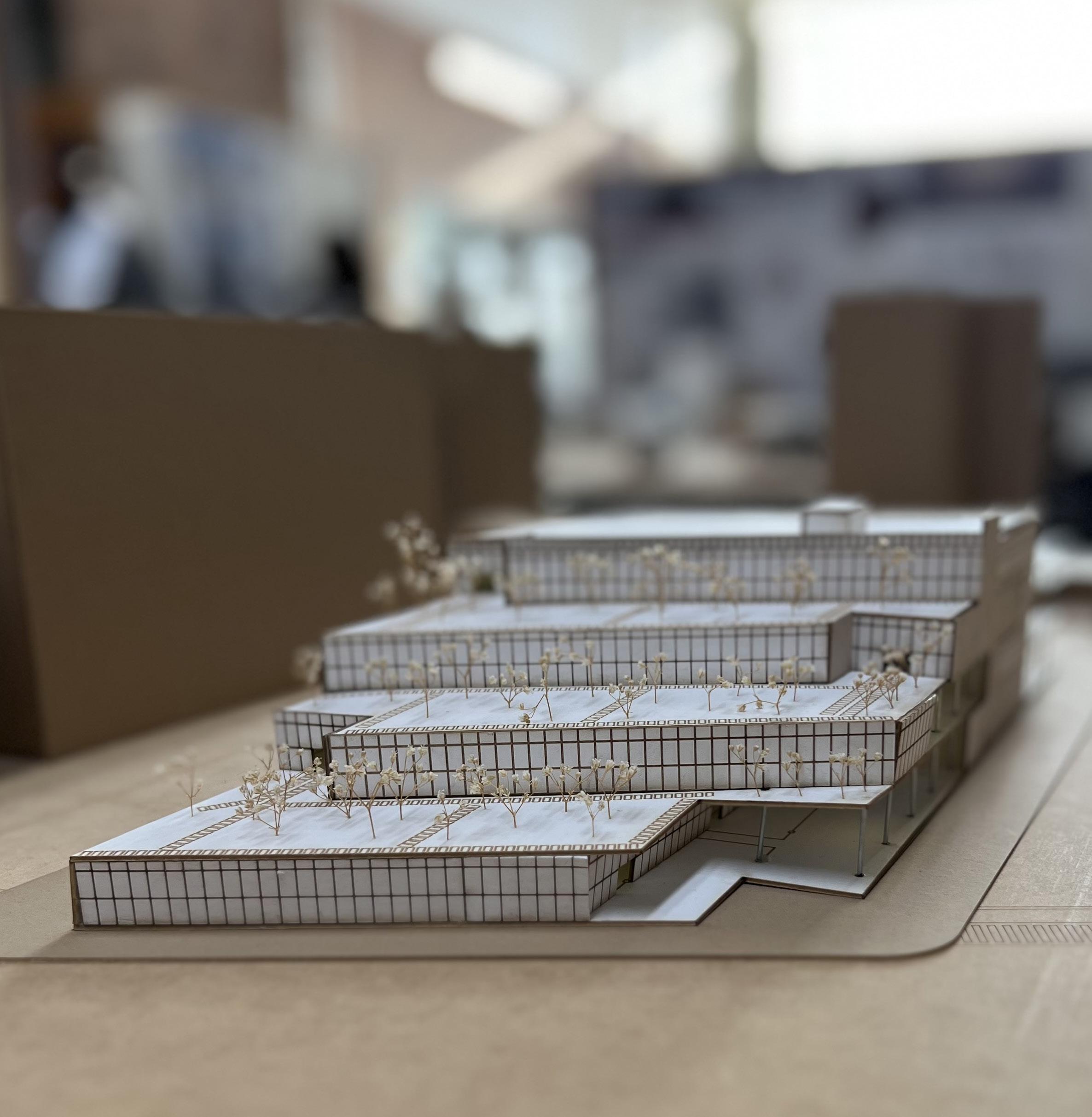
FINAL PHYSICAL MODEL - PART
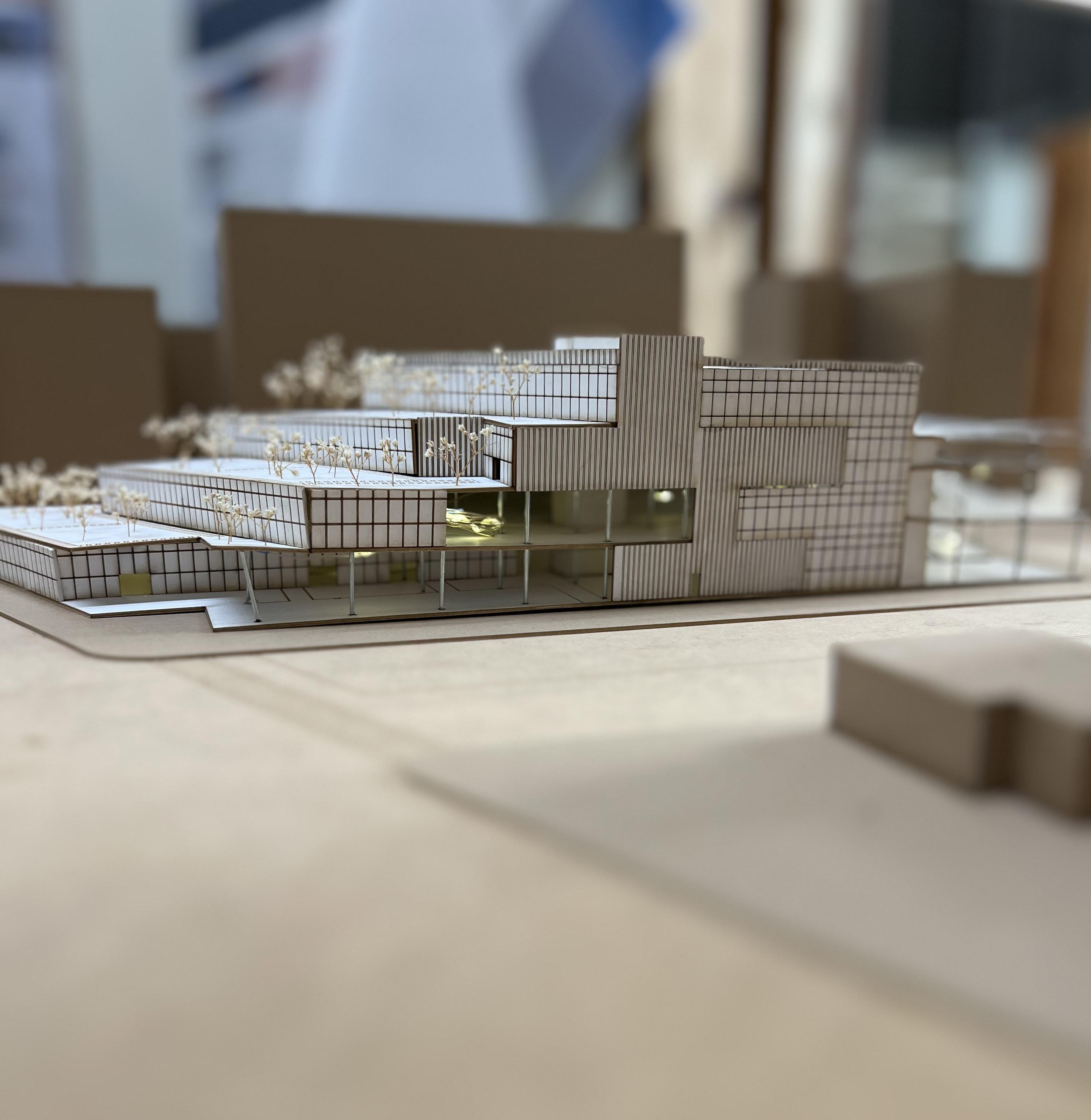
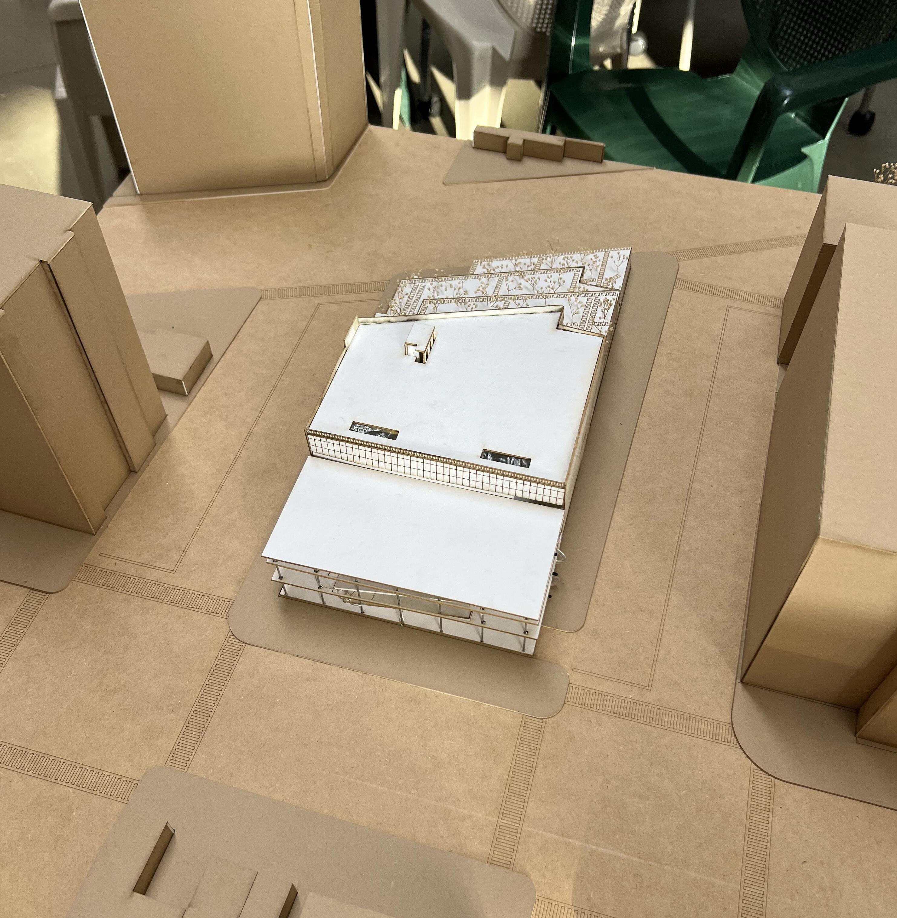
FINAL PHYSICAL DETAIL MODEL - PART 13