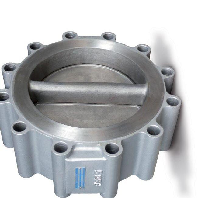
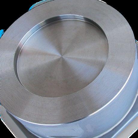
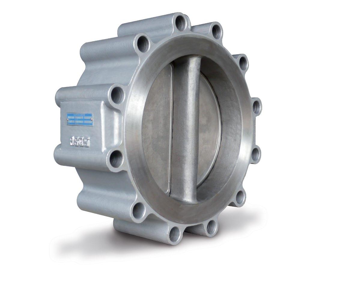
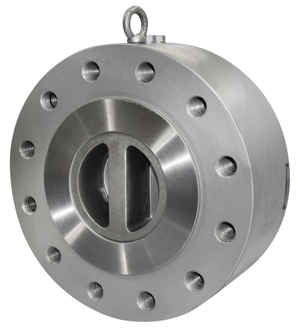
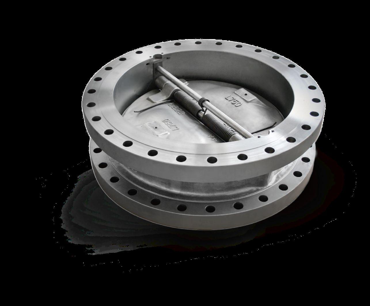
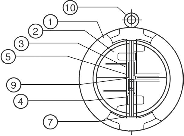
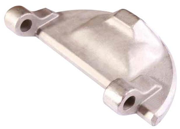
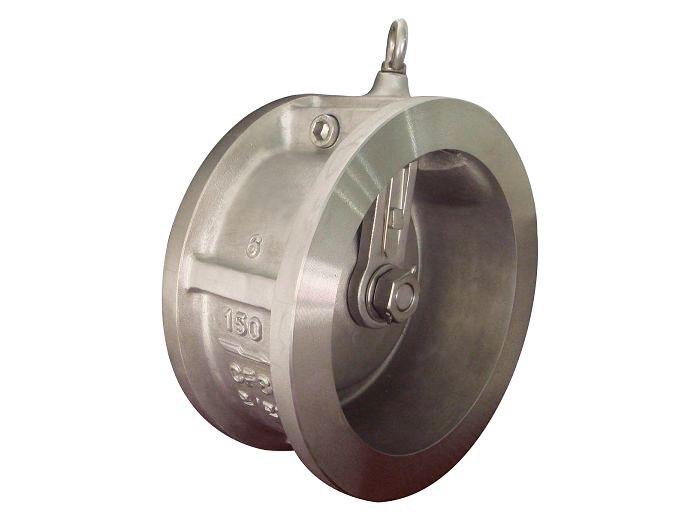
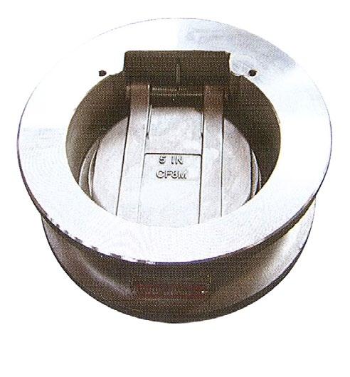
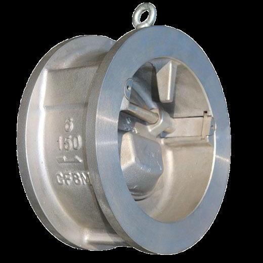
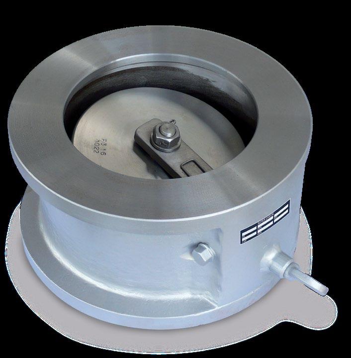
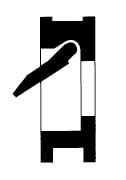
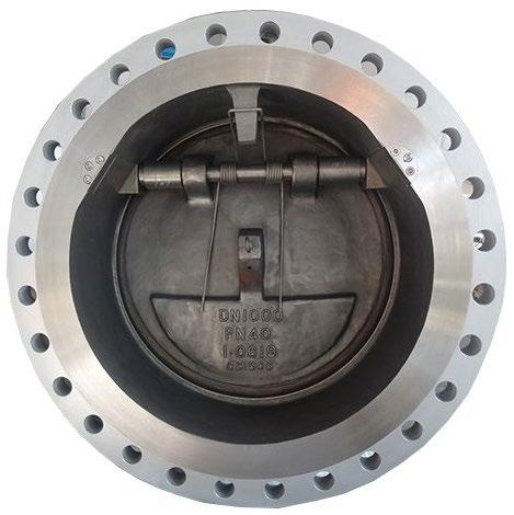
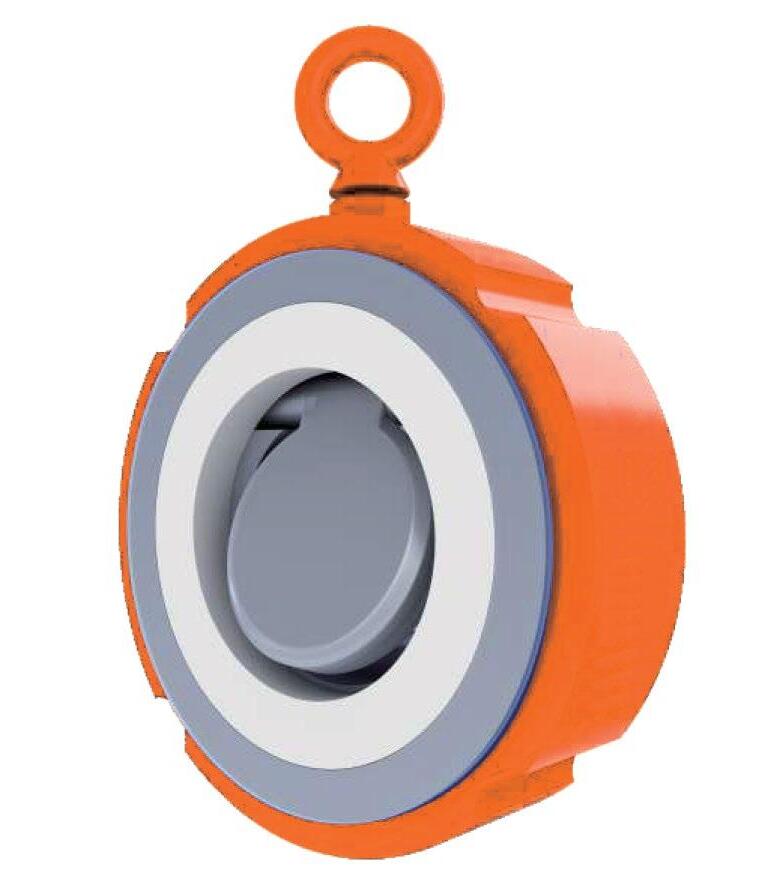
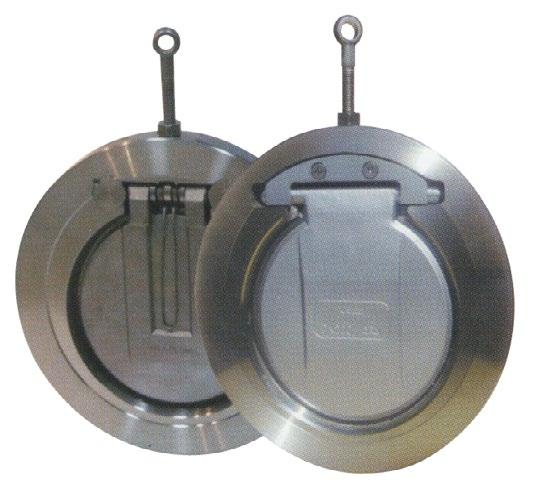
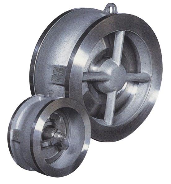
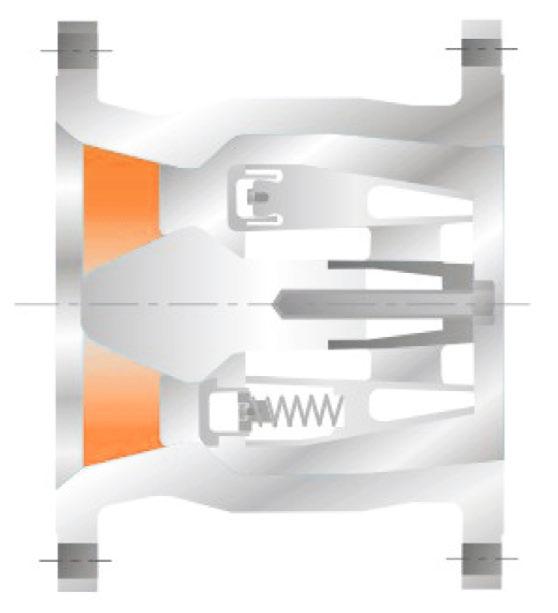
CHECK VALVES - WAFER STYLE
Firesafe Certified
Quality is Our First Priority.
Consistent product quality and a proven track record makes Australian Pipeline Valve a dependable choice where total reliability is the number one concern.
Since its founding, APV’s philosophy has been focused on quality. Our valves are manufactured in full compliance to worldwide standards (such as ASME/ANSI, API, EN, ISO, BS, AS).


Rating API 594 - Class 125/150 or AS/EN/ISO/BS PN10/ PN14/PN16
Design API 594, BS/EN 16767
Max temp -18°C* to 100°C Buna - N, -18°C* to 110°C EPDM, -18°C* to 121°C metal seat (As Body).
Flanging To suit ASA 125, 150, EN1092-2 PN10/PN16, AS2129 Table D, E, AS4087 PN14/ PN16/PN21, ISO 7005-1 PN10/PN16, AS4331.1 PN10/PN16, EN 1092-2 PN10/PN16, JISB 2220 5K~20K
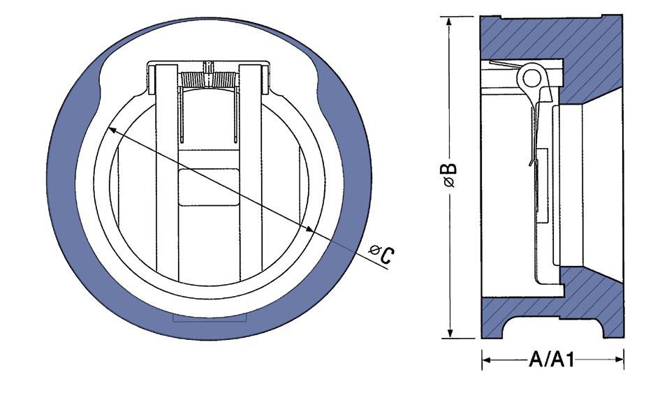
Face to Face EN 558 (was DIN 3203-K3), BS/EN 16767 or EN 16782 (3202-K3) or ASME B16
Test API 598/ISO 5208/MSS SP67-1
Metal seated leakage 3CC/min/inch of valve size per API 598.
Soft seated leak tight shut off.
* Iron body limitation -18°C
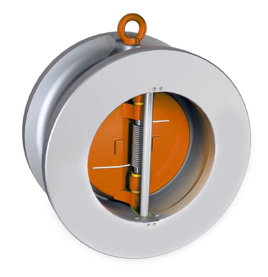
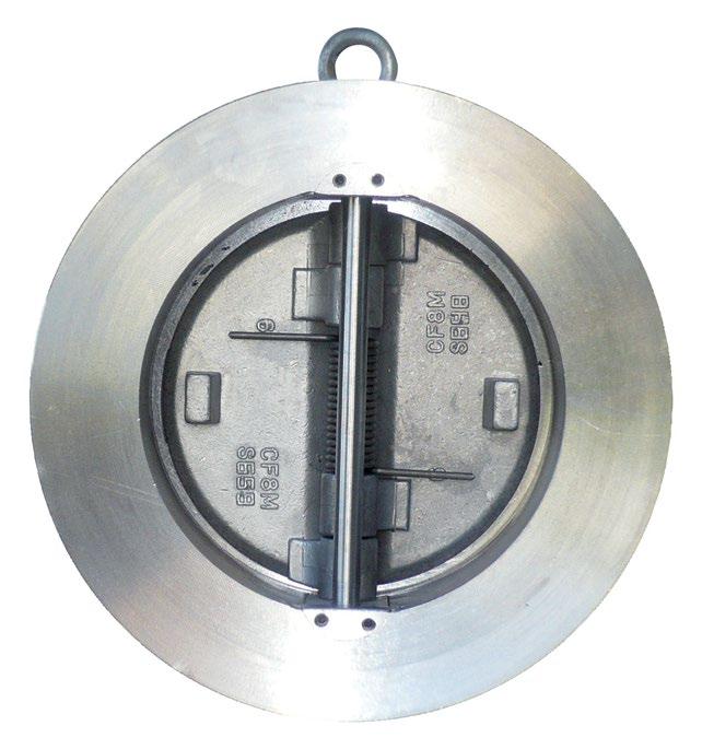
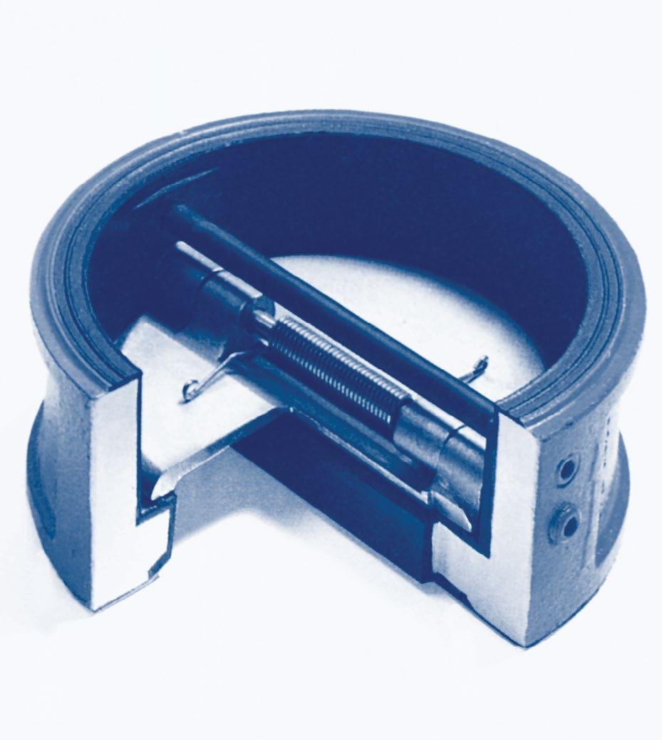
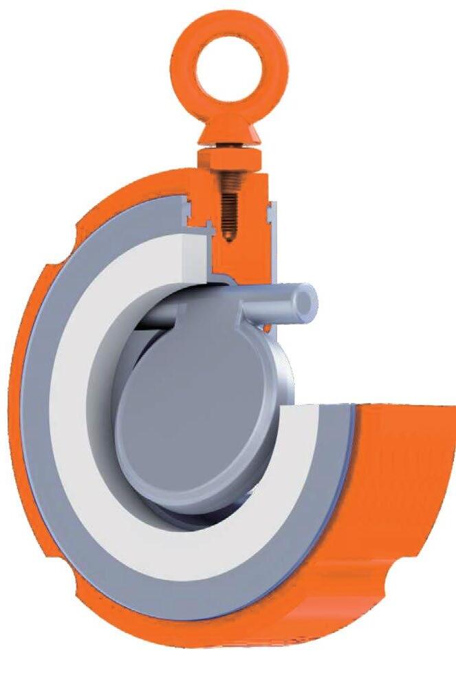
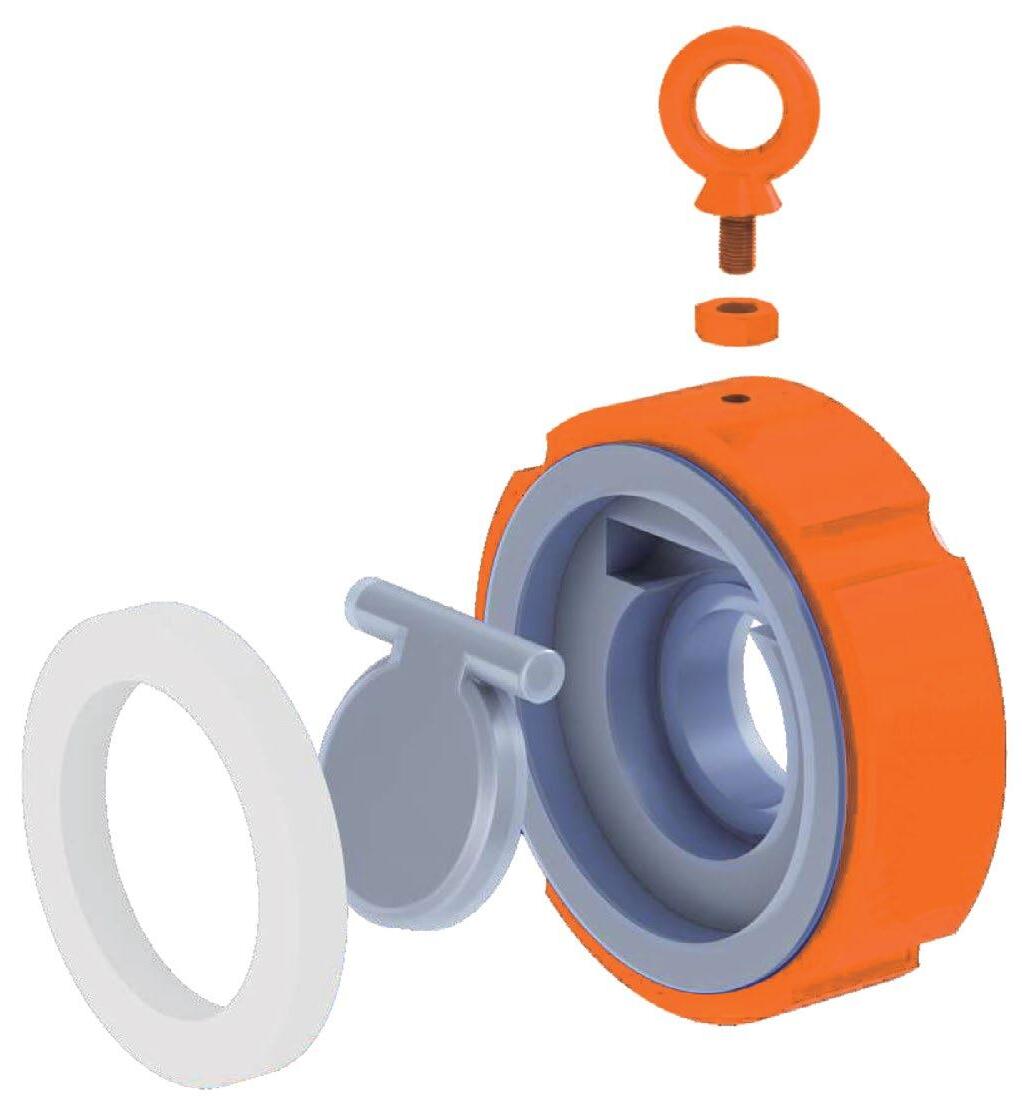
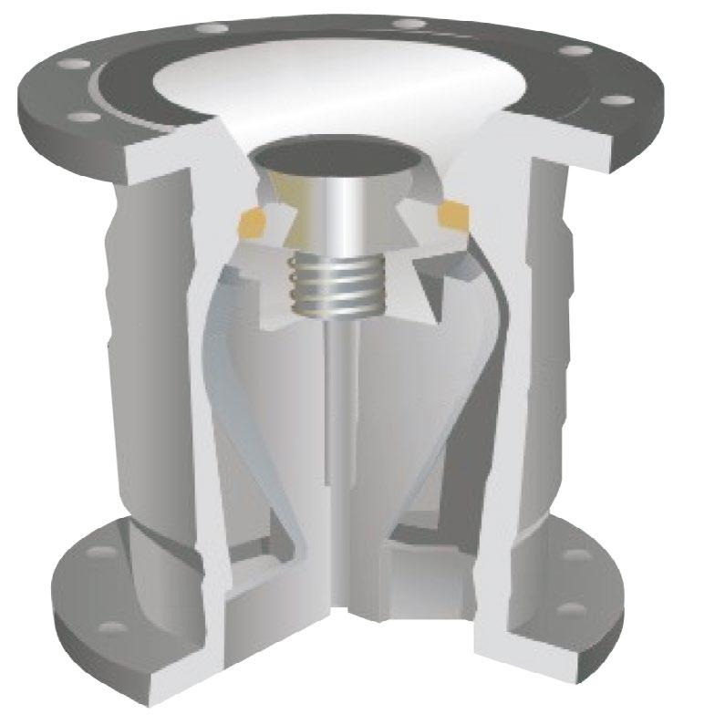
DESIGN FEATURES
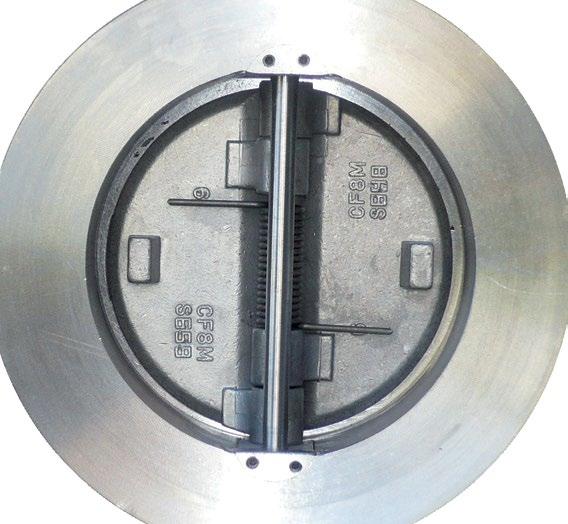
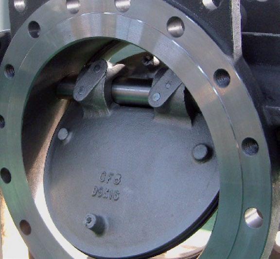
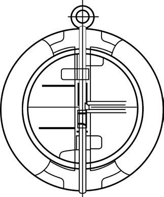
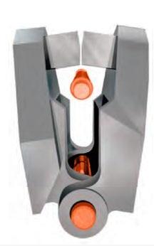
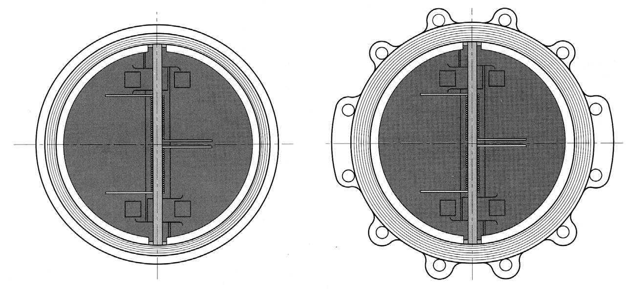
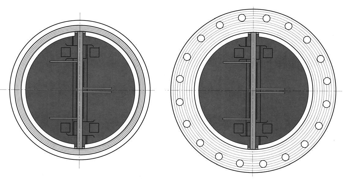
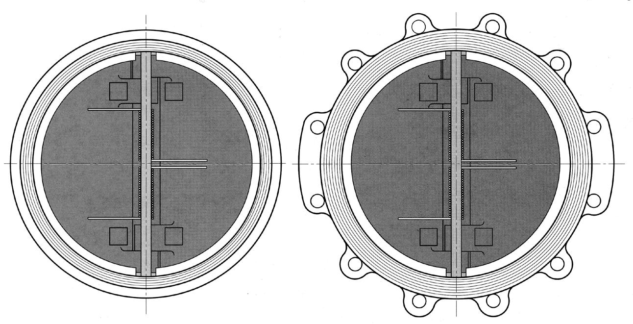
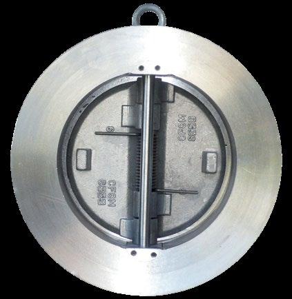
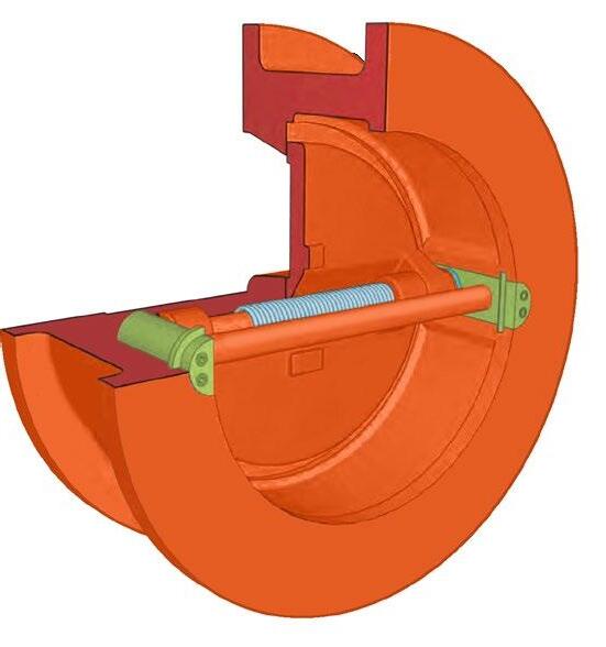
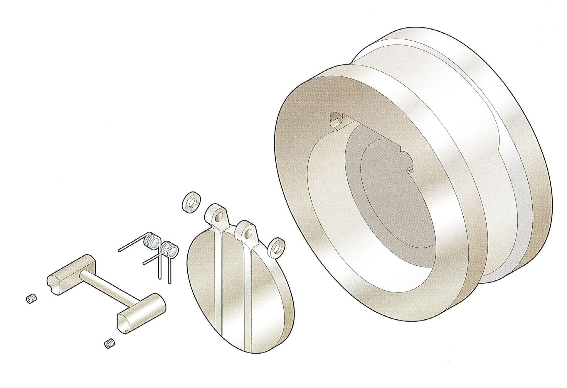
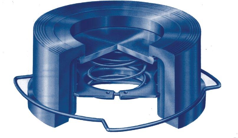
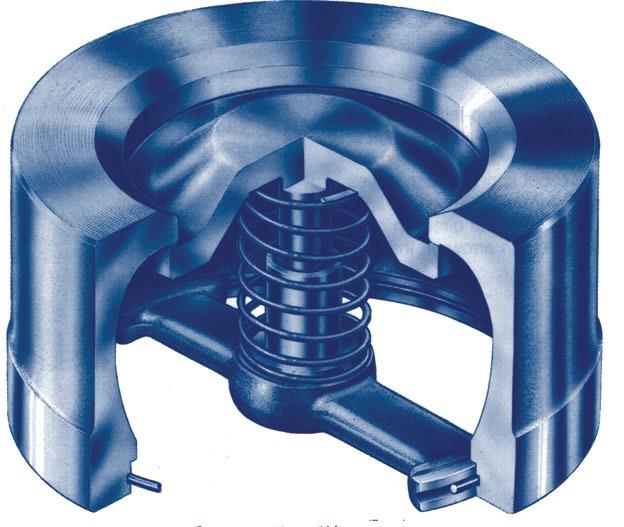
• Encapsulated and bonded body seat (soft seat)
• Upper and lower PTFE thrust bearings
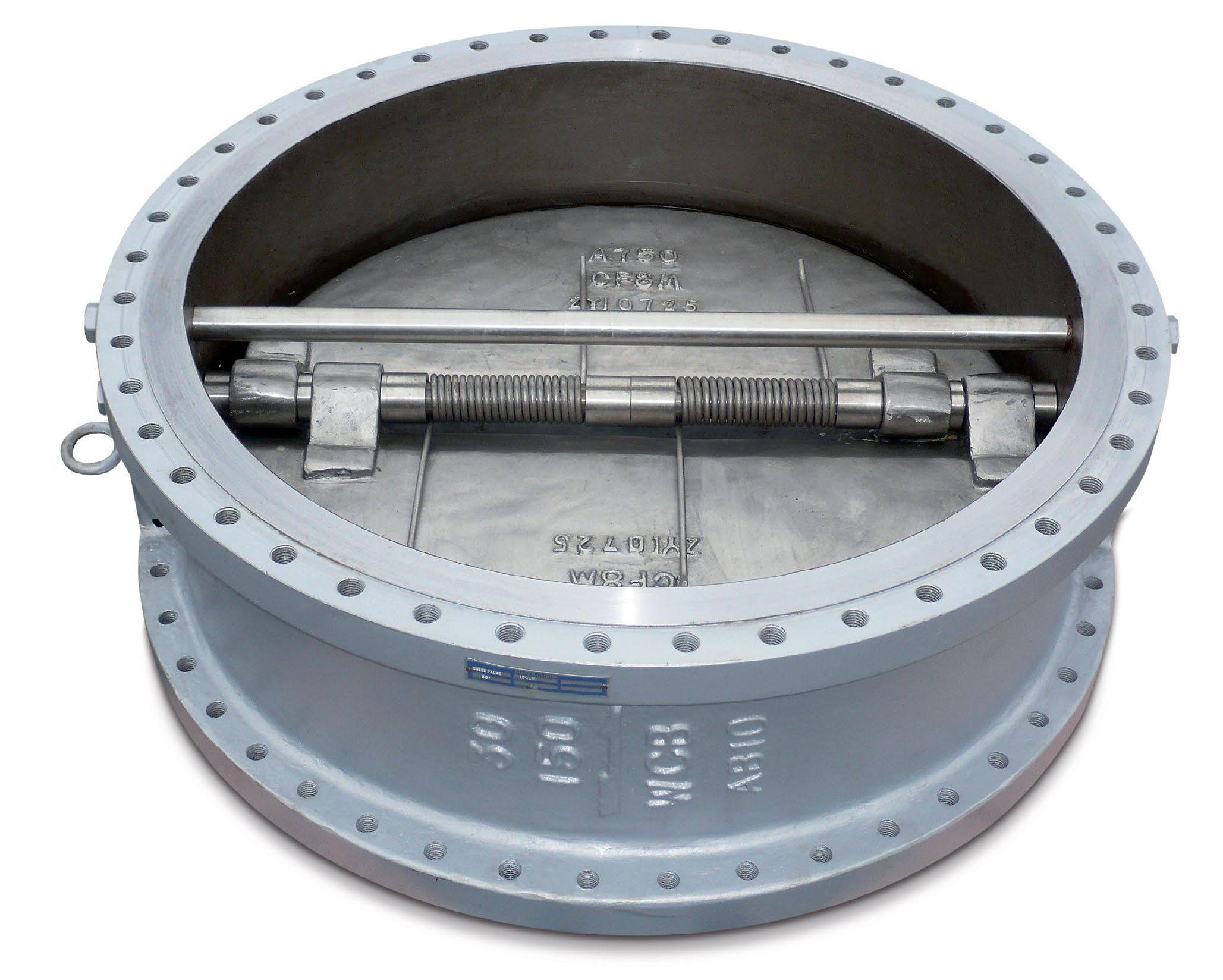
• Dual springs for quicker activation long life and even distribution of force over both plates
• Fusion bonded epoxy coated body (internal & external)
• Long leaf springs (prevent rubbing of disc and seat)
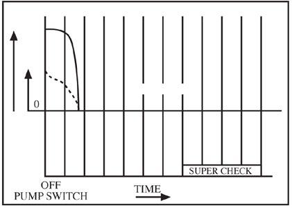
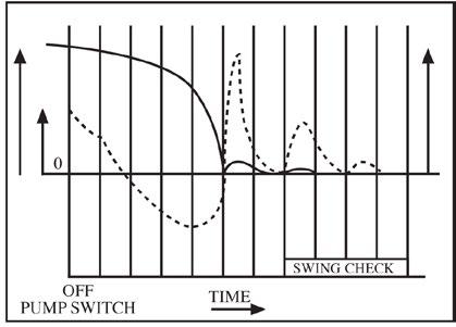
• Alleviation from Water Hammer
Reaction of torsion spring makes plates rapidly close prior to the start of reverse flow of fluid due to the stop of power, thus prevents damage from water, hammering caused by pumps and other reciprocating devices.
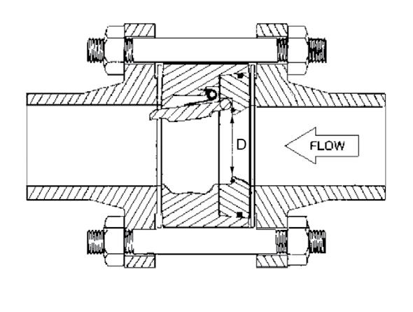
• Lower Head Loss
Designed with optimum venturi to reduce head loss when compared with similar Dual Plate Type Check Valves.
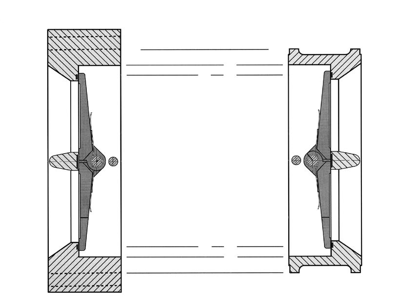
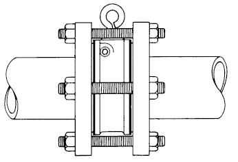
• Installation Directions In addition to the compact size, SUPER-CHECK valves can be installed either horizontally or vertically.
• Long Leg Torsion Spring Action which allows the plates to open and close without seat scrubbing.
• Super-Check provide a complete range of sizes from ND 40 through ND 1800, designed and rated in accordance with ANSI 125 LB, PN10, PN14, PN16, PN21

Ensure the valve is at least eight pipe diameters from
or
devices.
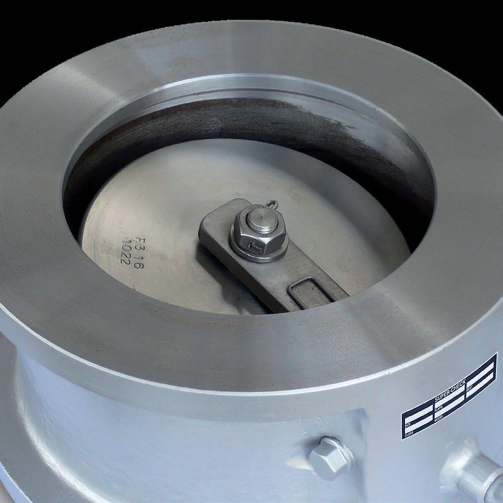
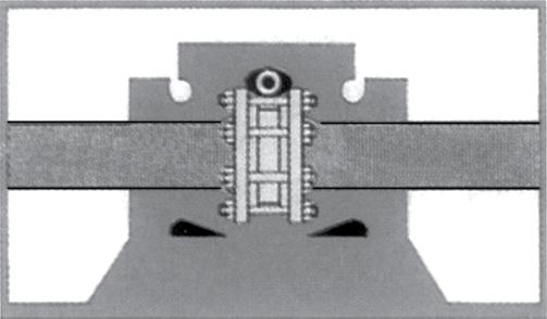
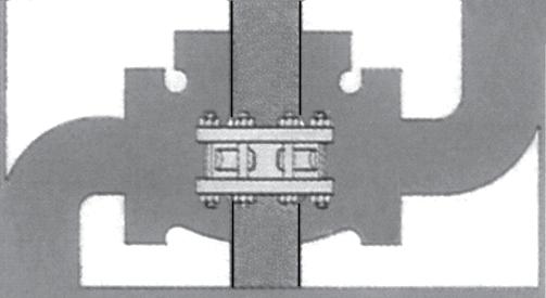
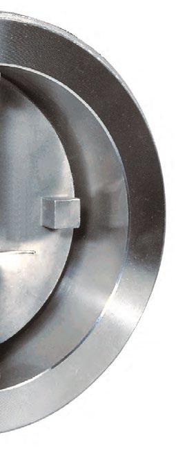
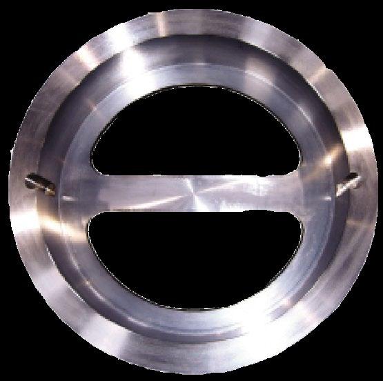
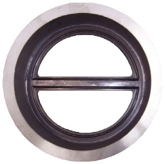
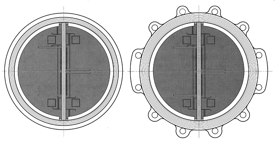
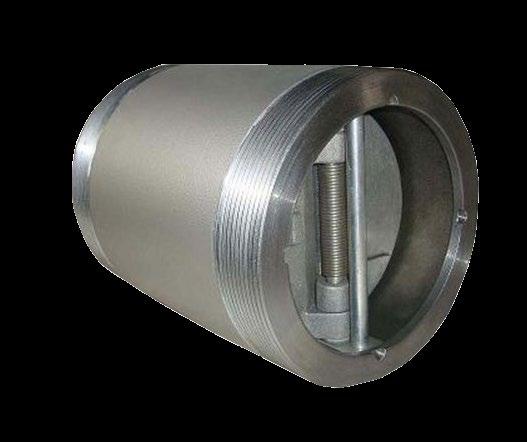
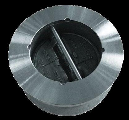
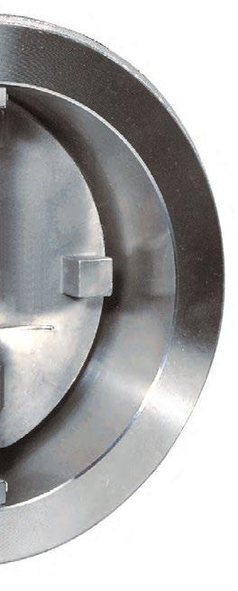
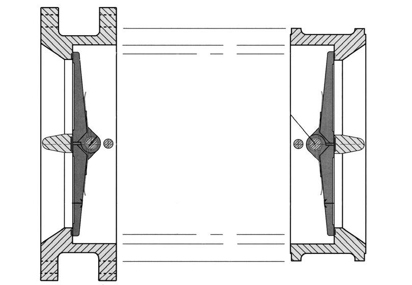
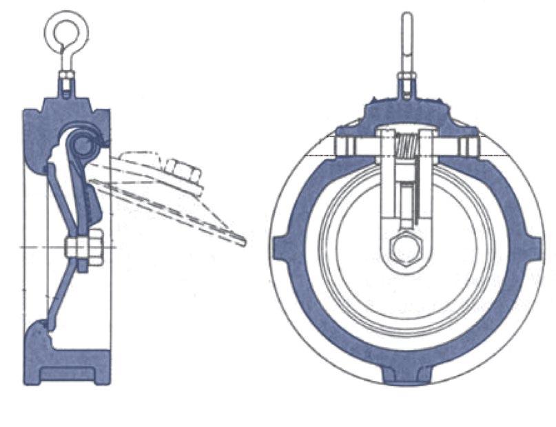
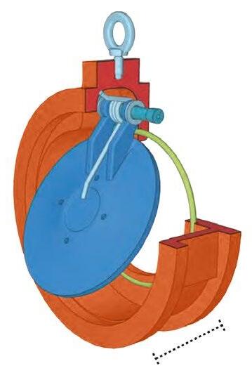
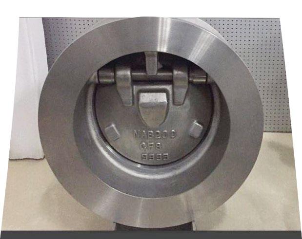
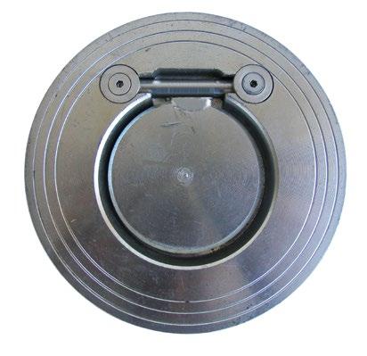
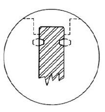
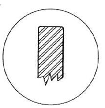
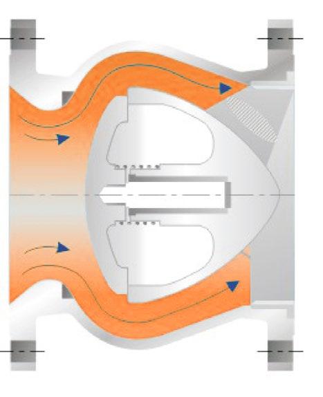
SLIM PLATE DESIGN
Standard in all sizes. Ensures lower cracking pressures & large flow rates.
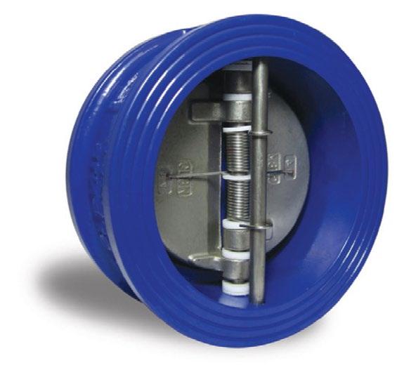
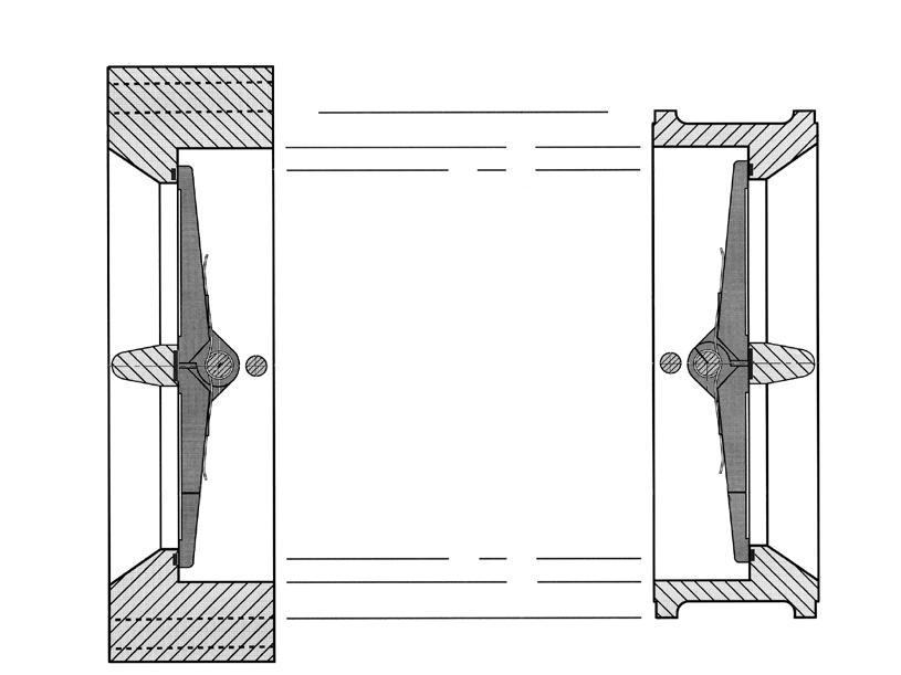
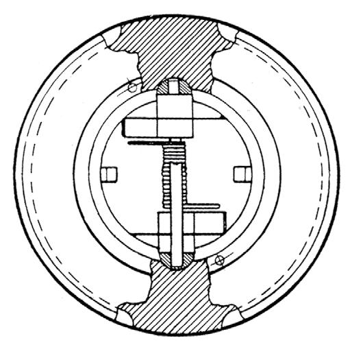
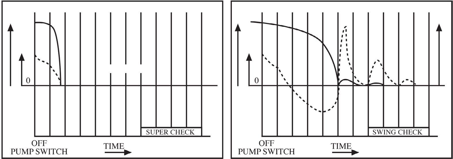
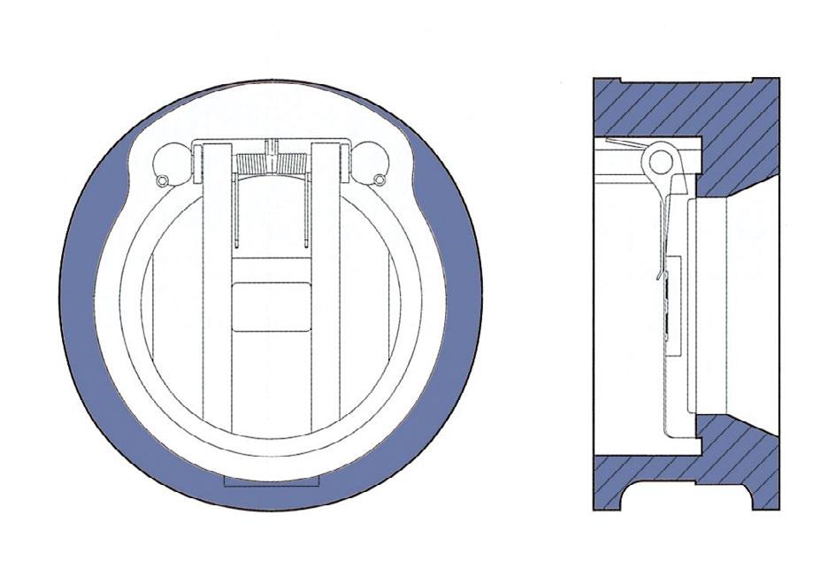
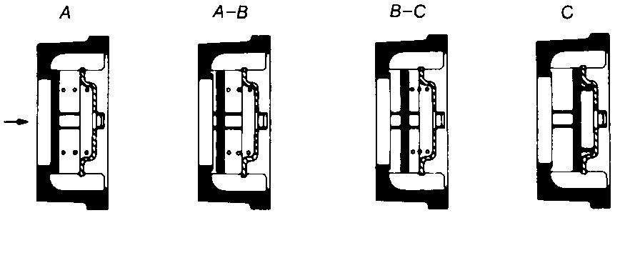
SUPER-CHECK is a non-slam check valve because it operates on flow cessation, not flow reversal. The normal position of the plates is closed, held against the seat by the unique spring design. As flow begins, the heels of the two plates are lifted off the seat face on the central rib.
This cracking pressure is less than 14 kPa (2 psi) across most of the range (larger sizes can be more). As flow increases, the plates then pivot against the spring pressure. Since the heels have already lifted off the seat there is no scrub or wear, either on the seat, body or plate seating surfaces. A pressure of only 28 kPa (4 psi) is required to keep the plates fully open (up to 400 NB).
When flow stops and the pressure ceases, the spring closes the plates. Flow reversal is then stopped by the closed Supercheck valve and in fact any back pressure only serves to make the valve seal more tightly.
• High performance non slam
• Face to face to API 594, wall thickness & design to API 594, test & inspection to API 598 flanging to ASME B16.5
• Vertical or Horizontal installation.
• Intrinsically Firesafe
• Very low head loss & minimum occupation of space
• Suitable to fit between ANSI 150, 300, 600, 900, 1500 & 2500 flanges as well as API, BS, AS, JIS, ISO, EN etc.
• Can be mounted horizontal or vertically
• Service Pressure
150 class 20 Bar (285 PSI)
300 class 51.1 Bar (740 PSI)
600 class 102.1 Bar (1480 PSI)
900 class 153.2 Bar (2220 PSI)
1500 class 255.3 Bar (3705 PSI)
2500 class 425.5 Bar (6170 PSI)
• Tight shut-off (resilient seat).
Metal seat 50% lower leakage than API 598 allows.
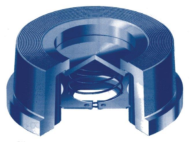
DESIGN FEATURES
• Alleviation from Water Hammer
Reaction of torsion spring makes plates rapidly close prior to the start of reverse flow of fluid due to the cessation of power, thus preventing pump and other devices from causing damage due to Water Hammering.
• Lower Head Loss
Designed with optimum venturi to reduce head loss and is comparable with similar Duo-check Dual Plate type Check Valves.

* Seat types - As per body, ST#6, HF, CR13, 316 † For other available trim configurations refer part number system.
In addition to the compact shape, SUPER-CHECK Valves can be installed either horizontally or vertically.
SUPERCHECK is a non-slam check valve because it operates on flow cessation, not flow reversal. The normal position of the plates is closed, held against the seat by the unique spring design. As flow begins, the heels of the two plates are lifted off the seat face on the central rib.
The cracking pressure is less than 21 kPa (3 psi) across most of the range (larger sizes and higher classes proportionately are slightly higher). As flow increases, the plates then pivot against the spring pressure. Since the heels have already lifted off the rib seat there is no scrub or wear, either on the rib, body or plate seating surfaces. A pressure of only 27 kPa (4 psi) is required to keep the plates fully open in 150 class, proportionately higher in other classes and larger sizes. (“Light” springs also available) When flow stops and pressure ceases the spring closes the plates. Flow reversal is then stopped by the closed Supercheck valve and any back pressure only serves to make the valve seal more tightly.
18 to 120
57 to 120 Neoprene
40 to 120
267 to 537 (As Body)
Viton-A (FKM) - 40 to 204
Viton-B - 29 to 200
The temperature range is a general guide. As temperature increase the pressure rating of the valve decreases. Ask for pressure/temperature chart. *Dependant on body material.
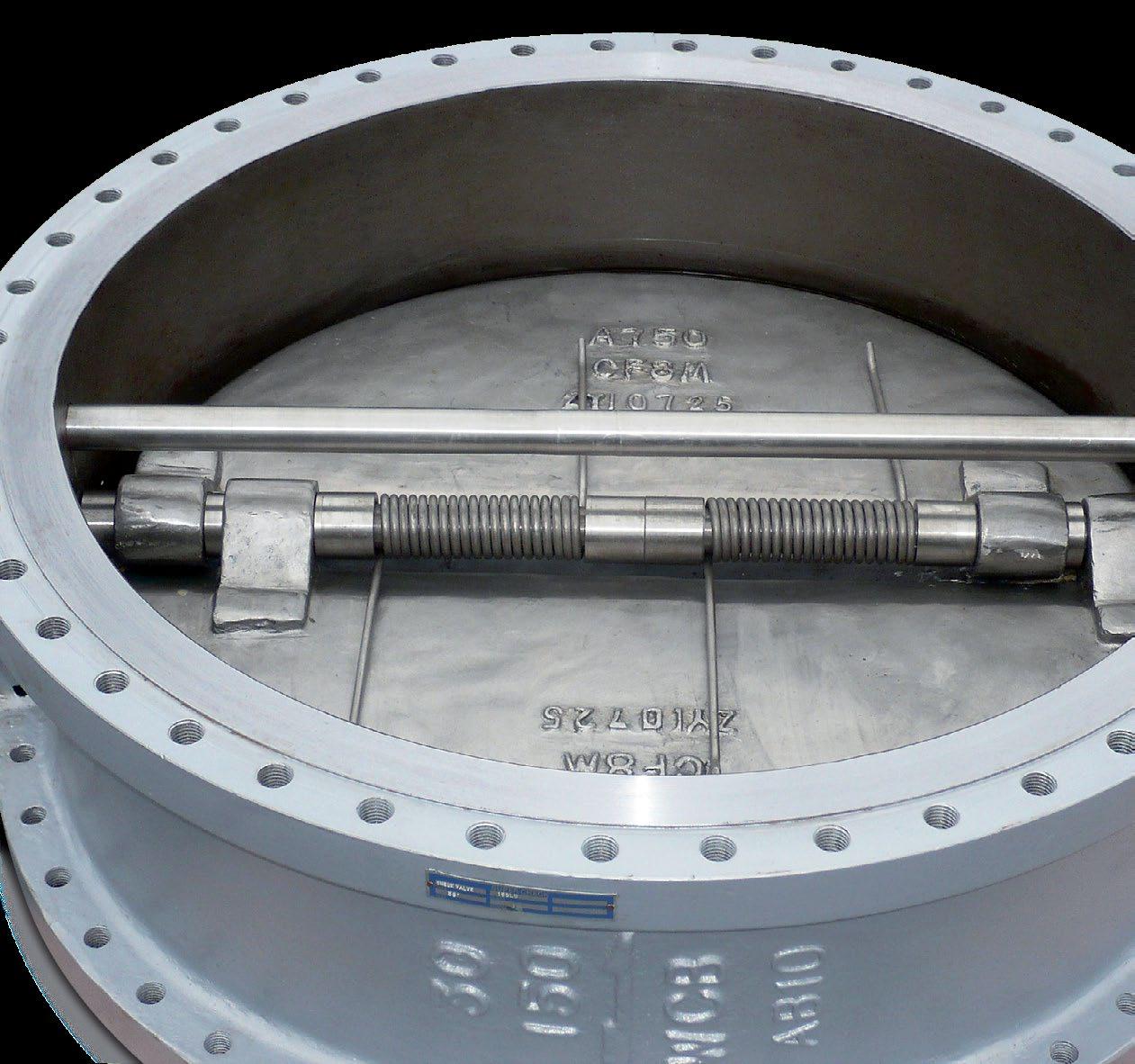
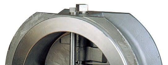
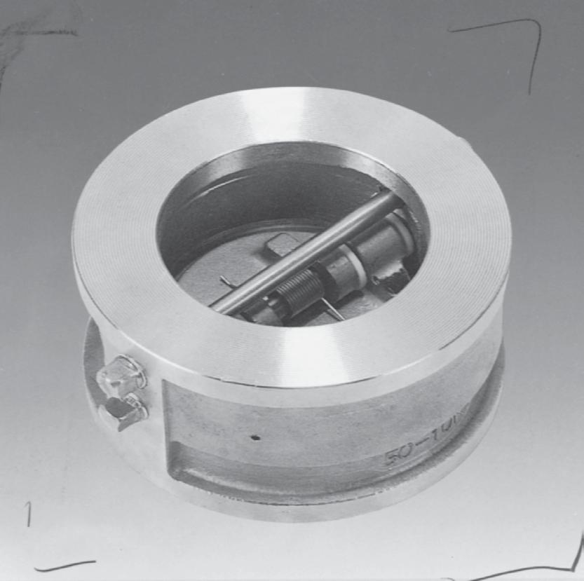
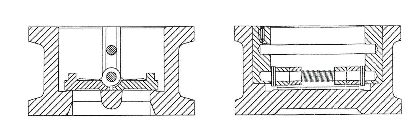
The problem Competitive designs do not have shock bumpers. The solution The Supercheck design where required in larger sizes (& higher classes) uses shock bumpers on the back of each disc. These bumpers meet when the valve is in the full open position, thus preventing the discs from striking the stop pin. This arrangement reduces the shock force on the hinges; ensuring internal components have an extended cycle life with minimal wear under the most severe service conditions.
Standard in all sizes. Ensures lower cracking pressures & large flow rates.
plugs
x 750 (Heat
API 598 metal seat allows a leakage of 3cc/inch of bore/minute. The Supercheck disc & seat faces are machined to obtain ≤50~66% lower leakage than API 598 allows.
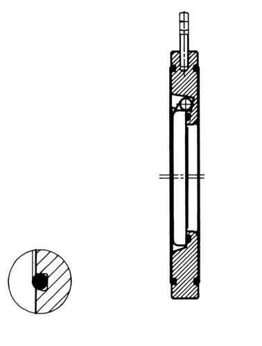
Increased seat life is ensured by eliminating the problem of the heel of plates dragging on the seat during opening. The soft seat is heat bonded and moulded into a recessed body groove. Supercheck soft seated valves are leak tight shut off. The disc floats on the seat lip and also makes metal to metal seat contact, providing a metal seat back up. HEAT BONDED RESILIENT SEAT
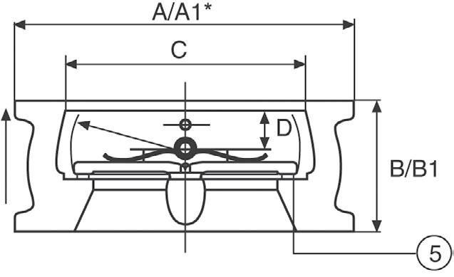
• 1-1/2” (40mm) Refer to drawings.
• Dimensions for larger valve sizes available upon request.
• Also available with API, BS, AS, EN and ISO dimensions.
• Approximate valve weight only.
• ***Threaded and Through-Bolt Lugged Body available.

* Minimum Flange Bore
** Stud and Bolt length is for Wafer Check with Raised Face End Connection. For Ring Joint End Connection contact us. *** Threaded and Through-Bolt Lug Body available.
• 1-1/2” (40mm) Refer to drawings.
• Dimensions for larger valve sizes available upon request.
• Also available with API, BS, AS, EN and ISO dimensions.
• Approximate valve weight only.
• ***Threaded and Through-Bolt Lugged Body available
* Minimum Flange Bore

** Stud and Bolt length is for Wafer Check with Raised Face End Connection. For Ring Joint End Connection contact us. *** Threaded and Through-Bolt Lug Body available.
• 1-1/2” (40mm) Refer to drawings.
• Dimensions for larger valve sizes available upon request.
• Also available with API, EN, API, BS, AS and ISO dimensions.
• Approximate valve weight only.
• ***Threaded and Through-Bolt Lugged Body available
• AD Dimensions for 30” and larger steel valves per ASME B16.47 & MSS-SP-44.
* Minimum Flange Bore. *** Lugged body also available.

** Stud and Bolt length is for Raised Face End Connection. For Ring Joint End Connection contact us. *** Lugged body also available.
• Approximate valve weight only.
• ***Threaded and Through-Bolt Lugged Body available.
2
3
Minimum Flange Bore
• Approximate valve weight only.
• ***Threaded and Through-Bolt Lugged Body available.
** Stud and Bolt length is for Wafer Check with Raised Face End Connection. For Ring Joint End Connection contact us.
*** Threaded and Through-Bolt Lug Body available.
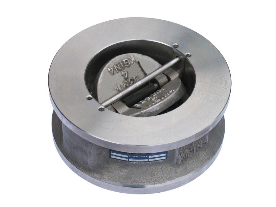
CHARACTERISTICS
• High performance non slam
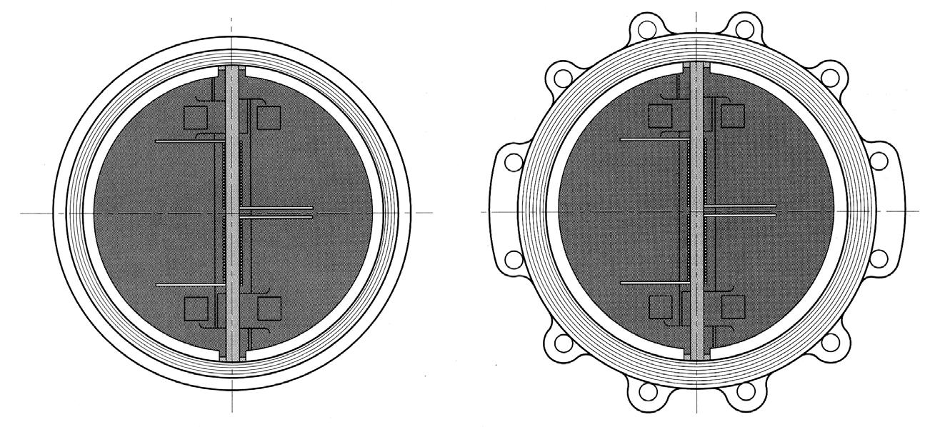
• Retainerless design meets fugitive emission requirements as there are no threaded plugs in the pressure boundary, thus eliminating potential leak paths. Slim plate design provides optimum flow & lower cracking pressures as well as longer life.
• Face to face to API 594, wall thickness & design to API 594, test & inspection to API 598, flanging to ANSI B16.5
• Vertical or Horizontal installation.
• Intrinsically Firesafe
• Very low head loss & minimum occupation of space.
• Suitable to fit between ANSI 150,300,600,900,1500 & 2500 flanges as well as API, BS, AS, JIS, EN, ISO etc
• Service Pressure
150 class 20 Bar (285 PSI)
300 class 51.1 Bar (740 PSI)
600 class 102.1 Bar (1480 PSI)
900 class 153.2 Bar (2220 PSI)
1500 class 255.3 Bar (3705 PSI)
2500 class 425.5 Bar (6170 PSI)
• Tight shut-off (resilient seat). Metal seat 50% lower leakage than API 598 allows.
Firesafe Certified
DESIGN FEATURES
• Alleviation from Water Hammer
Reaction of torsion spring makes plates rapidly close prior to the start of reverse flow of fluid due to the cessation of power, thus preventing pump and other devices from causing damage due to Water Hammering.
• Lower Head Loss
Designed with optimum venturi to reduce head loss and is comparable with similar Duo-check Dual Plate type Check Valves.
*Seat types - As per body, F6NM, HF, CR13, 316 † For other available trim configurations refer part number system.
API 598 metal seat allows a leakage of 3cc/inch of bore/minute. The Supercheck disc & seat faces are machined to obtain 50% lower leakage than API 598 allows.
Increased seat life is ensured by eliminating the problem of the heel of plates dragging on the seat during opening. The soft seat is heat bonded and moulded into a recessed body groove. Supercheck soft seated valves are leak tight shut off. The disc floats on the seat lip and also makes metal to metal seat contact, providing a metal seat back up.
HEAT BONDED RESILIENT SEAT
END TYPES


6
In addition to the compact shape, SUPER-CHECK Valves can be installed either horizontally or vertically.
SUPERCHECK is a non-slam check valve because it operates on flow cessation, not flow reversal. The normal position of the plates is closed, held against the seat by the unique spring design. As flow begins, the heels of the two plates are lifted off the seat face on the central rib.
The cracking pressure is less than 21 kPa (3 psi) across most of the range (larger sizes and higher classes are proportionately higher). As flow increases, the plates then pivot against the spring pressure. Since the heels have already lift seat there is no scrub or wear, either on the rib, body or plate seating pressure of only 28 kPa (4 psi) is required to keep the plates fully open proportionately higher in other classes and larger sizes. (“Light” springs
When flow stops and pressure ceases the spring closes the plates. Flow then stopped by the closed Supercheck valve and any back pressure only make the valve seal more tightly.
Operating Temperature Range for Seal Materials
EPDM - 18 to 110
Buna-N - 57 to 120
Neoprene - 40 to 120
Metal* - 267 to 537 (As Body)
Viton-A (FKM) - 40 to 204
Viton-B - 29 to 200
The temperature range is a general guide. As temperature increase the pressure rating of the valve decreases. Ask for pressure/temperature chart. *Dependant on body material.
The problem Competitive designs do not have shock bumpers. The solution The Supercheck design where required in larger sizes (& higher classes) uses shock bumpers on the back of each disc. These bumpers meet when the valve is in the full open position, thus preventing the discs from striking the stop pin. This arrangement reduces the shock force on the hinges; ensuring internal components have an extended cycle life with minimal wear under the most severe service conditions.
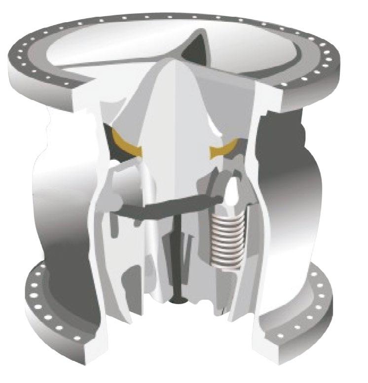
Slim Plate Design (all sizes)
Retainerless Body Design Eliminates potential leak paths to the outside and a stronger casting.
Independent Torsion Springs on large sizes respond quickly to fluctuations in flow velocity
Inconel X750 Springs are standard on all Carbon Steel and most Stainless Steel bodies.
Split Dual Disc Design minimises pressure drop and shortens the distance each disc travels.
Shock Bumpers stop discs and keeps them stable preventing unnecessary stress on the check valve
• 1-1/2” (40mm) Refer to drawings.
• Dimensions for larger valve sizes available upon request.
• Also available with EN, API, BS, AS and ISO dimensions.
• Approximate valve weight only.
• ***Threaded and Through-Bolt Lugged Body available
Minimum Flange Bore
(Continued)
** Stud and Bolt length is for Wafer Check with Raised Face End Connection. For Ring Joint End Connection contact us.
Threaded and Through-Bolt Lug Body available.
• 1-1/2” (40mm) Refer to drawings.
• Dimensions for larger valve sizes available upon request.
• Also available with EN, API, BS, AS and ISO dimensions.
• Approximate valve weight only.
• ***Threaded and Through-Bolt Lugged Body available
* Minimum Flange Bore
** Stud and Bolt length is for Wafer Check with Raised Face End Connection. For Ring Joint End Connection contact us.
*** Threaded and Through-Bolt Lug Body available.
• 1-1/2” (40mm) Refer to drawings.
• Dimensions for larger valve sizes available upon request.
• Also available with EN, API, BS, AS and ISO dimensions.
• Approximate valve weight only.
• ***Threaded and Through-Bolt Lugged Body available
• AD Dimensions for 30” and larger steel valves per ASME B16.47 & MSS-SP-44.
* Minimum Flange Bore *** Lugged body also available.
** Stud and Bolt length is for Raised Face End Connection. For Ring Joint End Connection contact us. *** Lugged body also available.
• Approximate valve weight only.
• ***Threaded and Through-Bolt Lugged Body available.
2
3
* Minimum Flange Bore
API 6FA-5th
Firesafe Certified
• Approximate valve weight only.
• ***Threaded and Through-Bolt Lugged Body available.
** Stud and Bolt length is for Wafer Check with Raised Face End Connection. For Ring Joint End Connection contact us.
*** Threaded and Through-Bolt Lug Body available.
A 4130/4140/A487 4C (API 6A)
C 316/CF8M Stainless Steel
D 304/CF8 Stainless Steel
F Alloy 20
G Low Temp. C.S. LF2/LCB
GC LCC Low Temp. Steel
H Cast Iron
HD Ductile Iron
12 ANSI Class 125
15 ANSI Class 150
25 ANSI Class 250
30 ANSI Class 300
40 ANSI Class 400
60 ANSI Class 600
90 ANSI Class 900
150 ANSI Class 1500
250 ANSI Class 2500
269 ANSI Class 2690
450 ANSI Class 4500
15000
AS14 AS4087* PN14
AS16 AS4087* PN16
AS21 AS4087 PN21
AS35 AS4087 PN35
BD12 AS/2129* Table D
BE12 AS/2129* Table E
ABF AS/2129* Table F
ABH AS/2129* Table H
PN6 ISO 7005/BS/EN/AS 4331 PN06
PN10 ISO 7005/BS/EN/AS 4331 PN10
PN16 ISO 7005/BS/EN/AS 4331 PN16
PN25 ISO 7005/BS/EN/AS 4331 PN25
PN40 ISO 7005/BS/EN/AS 4331 PN40
PN50 ISO 7005/BS/EN/AS 4331 PN50
PN110 ISO 7005/BS/EN/AS 4331 PN110
PN150 ISO 7005/BS/EN/AS 4331 PN150
PN260 ISO 7005/BS/EN/AS 4331 PN260
PN420 ISO 7005/BS/EN/AS 4331 PN420
* AS 4087 PN14/16 and AS 2129 Table D dual conforming.
N Monel
S Carbon Steel A105/WCB
SC WCC Steel
T CG8M/317 SS
U WC6/F11 Alloy Steel
V CF8C/347 SS
W CF3M/316L SS
X WC9/F22 Alloy Steel
Y C5/F5 Alloy Steel
AC Aluminium Bronze
AF F6A/410/CA15 Stainless Steel
BZ Bronze
CA CD3MN/4A/F51 Duplex SS
CB CE3MN/5A/F53 Super Duplex SS
CD C12 Chrome Molybdenum
CF CF3/304L SS
CH CW-12M Hastelloy C
CL WC4 Nickel Chromium Moly
CM WC11 Chromium Molybdenum
CN CN7M Alloy 20
CO C12 Chromium Molybdenum
CR CA6NM 18-1/2% Cr/Ni/Moly Steel
CS CA15 Chromium Steel
CV C12A Cr Molybdenum Vanadium
CW WC5 Nickel Chromium Moly
DY CD3MWCuN/6A/F55 Super Duplex SS FN Inconel® FU CU-5M CuC Inconel 825
FW CW6MC Inconel 625
FY CY40 Inconel 600
LC LC3 Low Carbon Steel (-101oC)
LN LC9 9% Nickel Steel
LT LC4 Low Temp. 4-1/2% Ni Steel
MO M35 Monel
NB Ni-Aluminium Bronze
TF B367 GR.C2 Titanium (F2)
TG B367 GR.C3 Titanium (F3)
TT Titanium
Z Special
* Body & plate are same material unless indicated by modifier suffix 11 indicating different plate material.
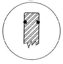
* Modifier suffix 11 indicates special overlay materials. P Seat is ‘as body’ if no modifier suffix. F Raised Face (serrated) B16.5
Raised Face B16.47B*/API-605
Raised Face B16.47A* (MSS SP44)
Raised Face BS 3293*
Buttweld
17-4 PH hinge and/or stop pin option.
for Alternate plates (flaps) &/or seat overlay 11
WCB Plates, Stellite Seat & Plates 72B WCB Plates, Stellite overlay Seat
304 Plates, Stellite overlay Seat 190 F51 Plates,
Seat & Plates
196 F53 Plates, Stellite Seat & Plates
197 F53 Plates, Stellite Seat
198 Ni-AL Bronze Plates, Stellite Seat
199 F51 Plates
200 Ni-AL Bronze Plates
201 F55 Plates
201 F53 Plates
203 Bronze Plates
204 Monel Plates
205 Monel Plates, Stellite Seat
999 Special
Do away with expensive full SS bodied valves. The TUF-SKIN is factory bonded over all “wetted areas” i.e. in bore & full faces Viton or EPDM or teflon over entire valve with S/S or A-Bronze trim. The external body can be epoxy coated. Only the outer body is iron, even the flange faces are fully encased by the liner. R in front of figure # denotes Rubber Check Tuf-Skin design. This design gives a much larger and together seating area for better seal and longer life. Also ideal where even stainless steel is subject to corrosion. This design prevents eventual leakage of o-ring seals normally used in soft seated duo-checks and also provides superior seal on flange contact area. The seat and flange face are both ribbed for superior sealing.
20 Bar Also Available
The SLP and SW Unicheck Swing Check Valve is available up to 700mm in various body materials and dimensions. The SW Series is retainerless. The SLP and SLP-T is non retainerless design and lends itself to applications requiring limit/micro switches, counter weights etc. The SLP and SW flapper has spring assisted closing, suitable for horizontal or upwards vertical service (downwards requires an external closing spring, which is an available option only in SLP and SLP-T Series). Design is to API 594 face toface dimension generally in accordance with ASME B16.10 short pattern/ API 6D long pattern and tested to API 598/ISO 5208. The SLP/SW series has a large bore providing a larger flow when compared to dual flap style or slim line uniflap checks. The SLP and SW 125 Class is ideal for waterworks & chemical service, whilst the 150 up to 1500 Class range is suitable for oil and gas service & has an intrinsically firesafe design.
SERIES (Through pinned)
Resilient, Soft Seat coupled with precision encapsulated machined sealing surfaces ensure a bubble tight seal ( Metal seat available)
Economical Design provides a highly efficient check valve with a larger port than dual flap valves that is inexpensive and has a short laying length.
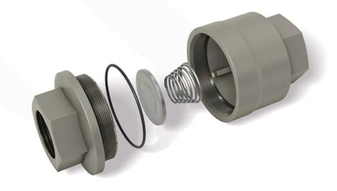
1. A truly dynamic seal, mechanically contained in a specially designed groove.
2. Unique in design and application.
3. As pressure is applied to the valve disc, the seal is compressed into the groove, ensuring a consistent and uniform seal.
4. The load on the seal is controlled reducing wear for longer life. Metal seated is also available.
Light and strong
Supercheck SLP/SW series valves are light, so line stress is reduced to a minimum. Yet the installed valve assembly is more rigid than an equivalent length of heavy-walled pipe.
Smooth, fully automatic operation
The SLP/SW series valves are designed to be fully automatic in function. The smooth opening and closing action reduces line hammer to a minimum. SLP/SW series valves are engineered to present an essentially unobstructed orifice.
Simplified design
The SLP/SW series are made with a minimum of parts. The stainless steel trim and resilient ‘O’ Ring seat (soft seat version) ensures long life. The single ‘O’ Ring ensures a complete leak-free seal.
SERIES
Type)
Inlet ports and disc have been shape optimized to achieve a fully open position at low flow rates. Therefore, the SLP/SW series operates exceptionally well in the flow rates typically found in pipeline containing control valves and lines with varying media flows.
Compare the SLP/SW series to typical full-sized swing check valves. Due in part to their oversized, heavier discs, these valves only fully open at larger flow rates. When activated at a lower flow rate, these valves lose true controllability and do not fully open. A partially open disc creates an obstruction that produces a higher pressure drop and fluttering of the disc valvedisturbing the flow & increasing the chance of water hammer.
SLP/SW Series will eliminate or reduce these problems.
DESIGN & PERFORMANCE STANDARD SERIES
SW RETAINERLESS
PERFORMANCE STANDARD
• ANSI B16.5 [1.5” up to 24”] - Flange Dimension
• API 6D/ANSI B16.10 - Face to Face Dimension
• API 598/ISO 5208 - Testing, allowable leakage rate
• ANSI B16.34 - Wall Thickness
RETAINERLESS DESIGN
The SW Series unique design doesn’t have a shaft hole bored through the body wall, unlike many competitors. This unique design prohibits any possibility of shell leakage and makes the valve inherently fugitive emission by design.
SW SERIES (Retainerless)
SW SERIES (Retainerless)
SW
SP01 Body
SP02 Disc
SP03 Insert
SP04 Hinge Pin
SP05 Spring
SP06 Washer
SP07 Set Screw

SW SERIES (Retainerless)
The SLP/SW Series valves elliptical shaped inlet and optimum diameter, plus its virtually unobstructed opening combine to produce a substantially higher flow capacity (Cv) than other wafer check valves.
The design of the SLP/SW Series will largely reduce or eliminate water hammer by closing the valve at the right moment (before reverse flow occurs).
Supercheck fully lined large port swing check valves are ideal for use in highly corrosive applications due to the universal chemical resistance of fluoropolymer lining.
These valves can be used in horizontal and vertical installations due to the special design of the hinge pin, which enables the disc to achieve a seal with out support of any system pressure.
2 Piece design eliminating a potential leak path with a seat face integrated in the body liner to seal against the disc in the closed position.
The disc can swing feely within piping system without interference with the diameter of the connecting pipe.
SPECIFICATIONS
Size 40mm-600mm (1.5”-24”)
Working pressure 0.1mbar-16 bar
Temperature range -20° C - 200° C according to working conditions, other temperatures on request.
Design and Manufacture
Easy to handle & installation
Lateral positioning groove connection according to standards. Perfecting material
Thick liner 100% inspected at 14000VDC for defects is made from highly corrosion resistant
Pure solid PFA disc long life use, super high-precision machining to make good seal science on-off performance
Wafer type body design
Lined securely locked into the body by “T” slots and locking grooves completely
Compare to pure plastic design, metal disc inside can avoid to break when suddenly shut
Retainer ring. Easy to pop-out & pop-in to replace the disc when abrasion
Epoxy coating paint
• 50NB thru 1000NB 150 Class to 900 Class
• Drop-In or Thru-Pin Clappers
• Material - Carbon Steel, Chrome Plate, Stainless, NI-Aluminium-Bronze, PTFE coated, Hastelloy, Titanium etc.
• API 6D Short Pattern, reduced bore (equal or better flow characteristics to a dual flap wafer check valve)
• Can be fitted with closing spring on request.
• Spring can be fitted around shaft to reduce chattering
• Super-Lite is lighter, smaller and therefore less expensive both to install and to maintain than conventional check valves. Because dual flap wafer checks are not only reduced bore but also have a central bar, superlite checks still have equal or better flow characteristics in most sizes.
• Simplified Design - There are only five parts in the Body of the Super-Lite.
• Will close at very low pressure (closes under weight of disc alone)
• O-rings housed in special profile grooves for high pressure with composition holes behind o-rings. Generally opens as low as 2 kPa minimum differential.
NOTICE
Do not install near rotating or reciprocating device, not suitable to withstand “hammering”
COEFFICIENT(CV)
OPTIONS
Face Type
* Nickel plated or galv on request.
O-Ring face, smooth finish*, RTJ or spiral face.
* Standard to 12”, o-ring face over 12” (depending on class)
Seals
Viton, Teflon, peroxide cured Buna-N, EPDM etc.
TEMPERATURE
NBR -40 to 90°C, FPM/Viton 150°C, PTFE -30° to 200°C
Metal to Metal will do higher temp up to 350°C
SERVICE
Steam PTFE (only up to 200° C)
Hot Water (Subject to temperature)
Air, Oil, Water, NBR, Viton, Buna, PTFE any
• The flow coefficient (Cv) is the flow of water in US gallons/min passing through a valve with a resulting pressure
PART LIST
1. Body
2. Clapet + Pin
3. Eyebolt
4. Body O-Ring*
5. Seat O-Rings
6. Screws
7. Washer
* Optional smaller sizes
A rubber flapper can be supplied, which also acts as a body gasket. This design is light weight, cheaper to make easy & cheap to change clapper, low wearing & maintenance free. Can be supplied in Buna, EPDM etc. The same dimensions & bore sizes etc. apply, suits low pressure applications.
O-RING
O-Ring in conjunction with serrated face. Designed so that either type will provide effective sealing surface. Only required in larger sizes.
WORKING PRESSURE
CLASS 125/BST-D/BST-E/PN10
To 300NB - 200 PSI CWP (oil, water etc.)
350 to 600NB- 100 PSI CWP (oil, water etc.)
Available to suit -40°C to 200°C. (Pressure rating drops for higher temperature applications)
Over 200°C on request.
CLASS 150/300
ANSI 150 - 280 PSI CWP
ANSI 300 - 720 PSI CWP
ANSI 600 and ANSI 900 available up to 450NB PN14~PN35 as per AS 4087/AS 4331.1/ISO 7005-1
Available to suit -40°C to 200°C. (Pressure rating drop for higher temperature applications)
Over 200°C on request.
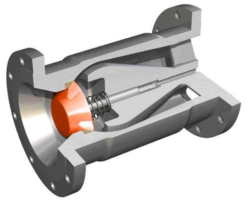
Retainerless Body eliminates potential leak paths to the outside and is a stronger casting
Simple Design is reliable; there are no springs or flange gaskets to replace
Gravity Assisted Disc opens and closes under low differential pressure conditions with minimal head loss.

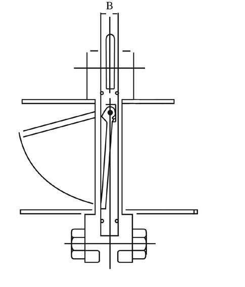
• Full Flow Piston Check
• Face to face conforms to DIN 3203 part 3-k4
• Investment casting
• PN20, PN40 DIN 3202 K5, DIN 3202 K4
• Standard configuration only suitable for liquid service. Consult us if you use for air/gas service.
1
SC01, DN 15-100 mm (1/2”-4”) with special centering ring (optional)
SC02, DN 15-100 mm (1/2”-4”) with self-centering body DEGREE OF OPENING
Degree of opening of a spring-assisted non-return valves as a function of volume flow
PARTS MATERIALS
SC03, DN 125-200 mm (5”-12”) (Stem guided piston check)
PTFE & PP BODY ALSO AVAILABLE * Absolute maximum range at 0 PSI and dependent upon materials and trim. Up to 400°C possible depending on spring. However, severe pressure limitations apply as temperature increases (400°C limit is zero PSI)
*PN40 will multi fit ANSI 150 & ANSI 300
MODEL R-APSC-V
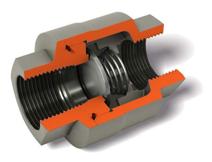
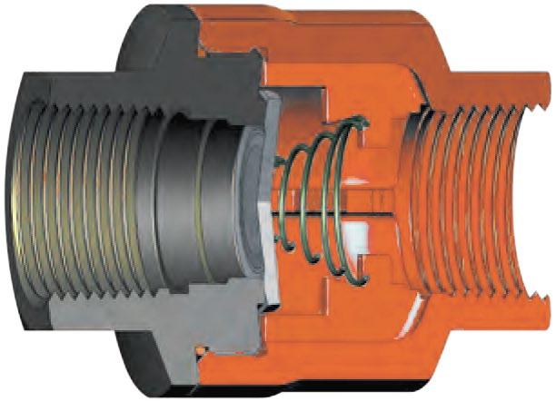
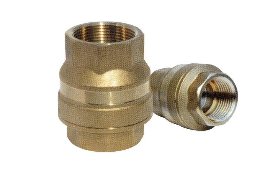
The Supercheck R-APSC-V is our versatile, low maintenance, ‘non slam’, spring assisted, problem solving check valve. This threaded inline check valve is mountable vertically or horizontally and prevents water hammer and flow reversal. Fit it and forget it! The 316 SS body, body-guided disc and seat ensure corrosion resistance for most mediums and lapped seats & disc provides tight shut-off.
• Sizes from 1/2” to 3”
• NPT, SW or BW ends.
APPLICATIONS
• CONDENSATE
• WATER
• STEAM
• CHEMICALS
• NITROGEN
• WATER INJECTION
• BOILER FEED
• FLARE LINES
• AMMONIA
• CRYOGENIC
• OXYGEN COOL DOWN
OPTIONS
• Hastelloy C
• Alloy 20
• SEVERE Chemical Service
• Soft seat for bubble tight shut off
• NACE
• Higher cracking pressures
Body Seal (4) Zelon (243°C max.) or Buna-N Zelon (204°C max.) or Buna-N Option: Body seal weld (371°C max.)
3 Optional Buna-N or Zelon soft seats for bubble tight shut off.
4 Only Zelon is suitable for steam. Buna-N is required for CO2 resistance / NACE service.
(1.) Cracking pressure (PSIG) (2.) Maximum Temperature for Buna-N (3.) ASME B16.34-2004
(4.) Maximum temperature for Viton® and Zelon w/3600 PSI CWP, R-APSC-V. (5.) Maximum temperature for Zelon w/750 PSI CWP, R-APSC-V.
• Design to API 6D and Face to Face Distance as per manufacturer’s standards.
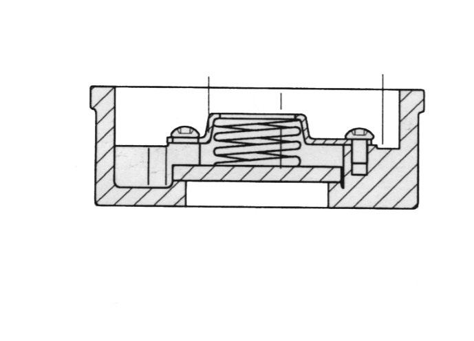
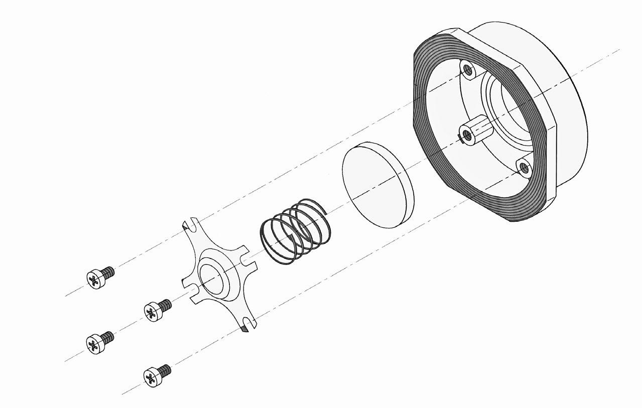
• Fast acting spring prevents water hammer and pressure surge, this is a truly Non Slam Check Valve.
• Short Travel and Ultra Light weight Disc make the advantages of Non Slam Check Valves possible & reduces water hammering. Quick closing and fast travelling disc are the fundamental design features.
• High Velocity and Gas Flow under compressed conditions can reach sonic velocity and the ‘sonic booms’ are detrimental to the valves operation. The simple but precisely calculated spring design overcomes this problem.
• Bernoulli’s equation of conservation of energy is the solution for spring design. Velocity head exchanges the energy with Pressure Head and the Supercheck Non Slam Check keeps on performing without the fear of sonic boom and valves offer low Pressure Drop when compared to Dual Plate Check Valves static pressure. Dropping the velocity head at vena contracta increases static pressure reducing cavitation.
• Single piece body construction allows High Pressure Applications and Non Slam Nozzle Check Valves are inherently Fire Safe.
• Rating ANSI Class 150, 300, 600, 900, 1500 & 2500 & up to 10,000 psi.
• Material ASTM A105, A182, Gr. LF2, Gr. F316, Gr. F51, Gr. F55 etc.
• Designed using Computational Fluid Dynamics (CFD)
• Low head loss & minimum pressure loss can be achieved.
• Metal to Metal seated design.
• Conical seating surface is self aligning & provides tight shut off.
• Spring loaded disc design allows mounting in any orientation.
APPLICATIONS
• Chemical, Oil & Gas Industries
• Residual Heat Removal Systems
• Nuclear Power Plants
• Offshore & Onshore Production Platform, FPSO
• Containment Isolation
• Water, Steam, Gas, Vacuum
• Steam Injection Systems
• Power Station, Water Pumping Stations
• Natural Gas, Refineries
• Critical Equipment Discharge
• Gas Compressor Unit
• Cracker Plants
• Non Slam Closure
• Extremely quick Closure
• Low Pressure Loss
• Short stroke of disc
• Axial movement of disc
• Disc’s minimal wear characteristics

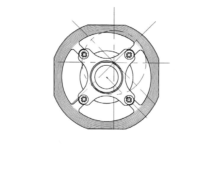
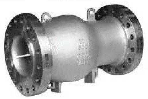
Single Spring Loaded Nozzle Check Valve
Up to 250NB (10”) and 150~300LBS single spring loaded design (Model Number: SW-NCA) minimum pressure loss with excellent dynamic performance.
Multi Spring Loaded Nozzle Check Valve
250NB (10”) and above 150~2500LBS multi spring loaded design (Model Number: SW-NCB) minimum pressure loss with excellent dynamic performance.
Example Only. Refer to as built drawings. (FL-NCFO Series) also refer to drawings as all dimensions are different.
ANSI INSTALLATION DIMENSIONS
Dimension for larger valve sizes available upon request. Also available with JIS, DIN, BN, AS and ISO dimensions. API 2000, 3000, 5000, 10000 also available.
Supercheck Nozzle Check valve is designed to meet the criteria of conventional check valves by allowing forward flow under normal conditions, opening easily and firmly backseating at low velocity.

Example Only. Refer to as built drawings. (FL-NCFO Series) also refer to drawings as all dimensions are different.
ANSI INSTALLATION DIMENSIONS
Dimension for larger valve sizes available upon request. Also available with JIS, DIN, BN, AS and ISO dimensions. API 2000, 3000, 5000, 10000 also available.
Supercheck Nozzle Check valve is designed to be closed prior to reverse flow as non-slamming with a spring loaded disc that allows mounting in any orientation.
ANSI 900 SW-NCA Single Spring
SW-NCB Multi Spring
Example Only. Refer to as built drawings. (FL-NCFO Series) also refer to drawings as all dimensions are different.
“Australian Pipeline Valve produces isolation, control and flow reversal protection products for severe and critical service media in utility, steam, pipelines, oil & gas and process industries. APV valves and pipeline products form the most competitive portfolio in the market.”