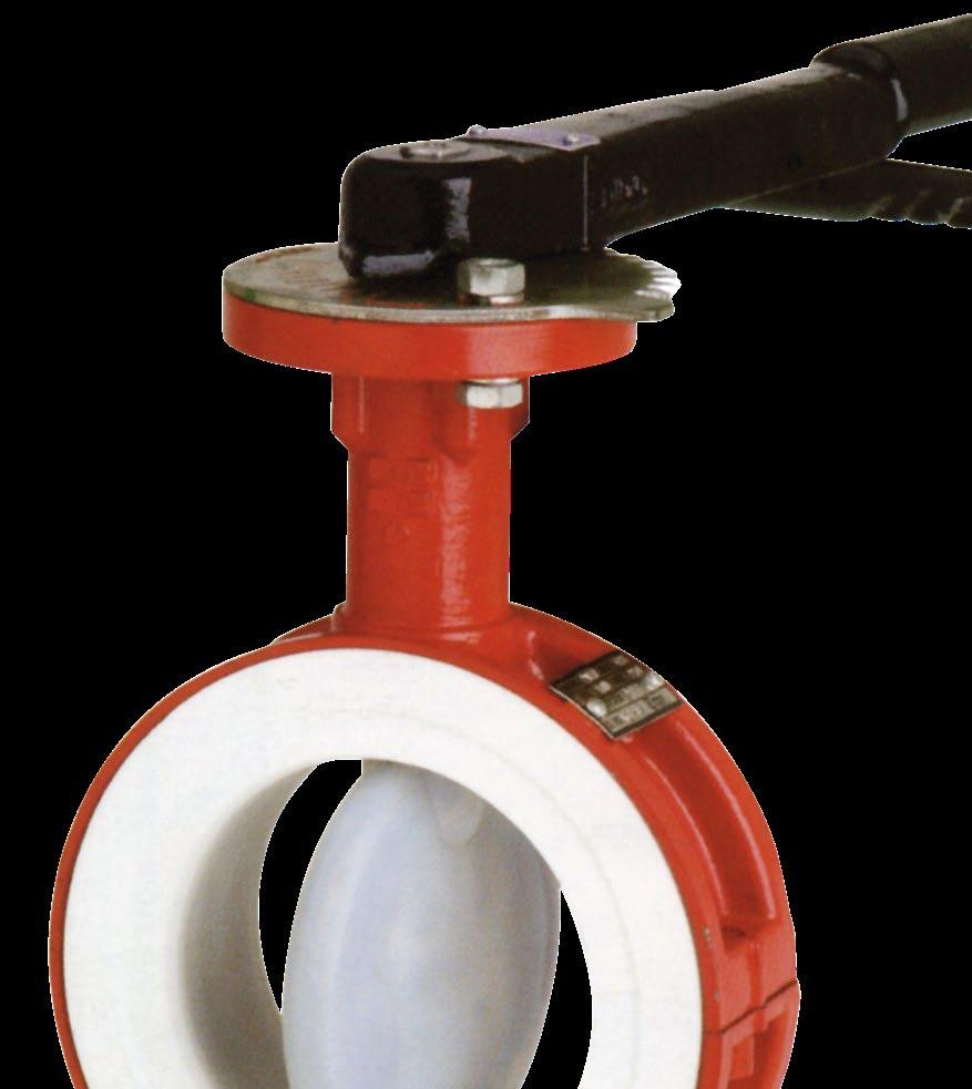
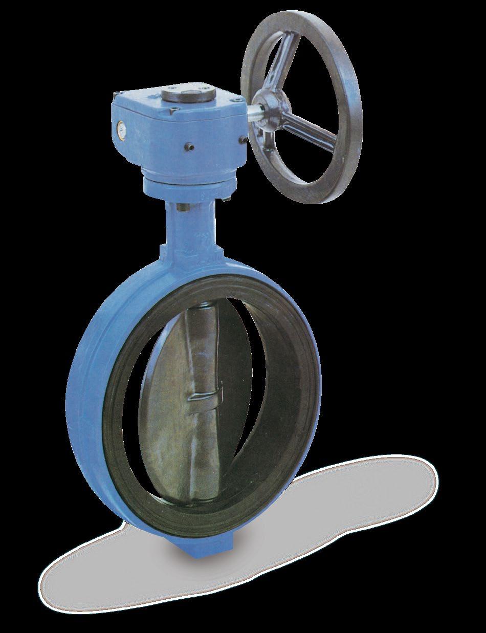
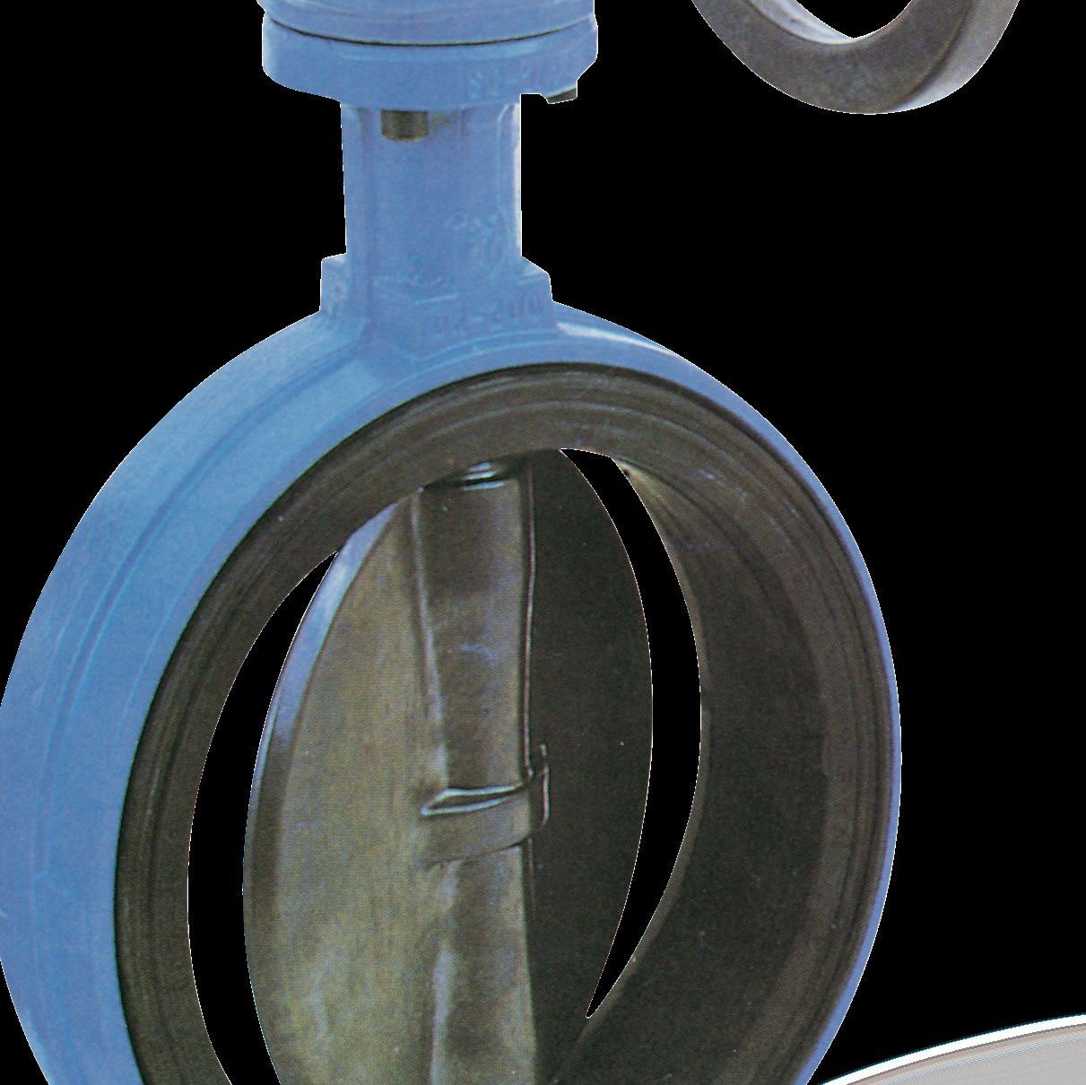
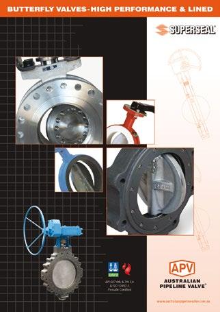
LINED BUTTERFLY VALVES
MODEL 2014 & 2016 SERIES
www.australianpipelinevalve.com.au INSTALLATION, OPERATION & MAINTENANCE MANUAL
COMPLETE PRODUCT LINE
“Australian Pipeline Valve produces isolation, control and flow reversal protection products for severe and critical service media in utility, steam, pipelines, oil & gas and process industries. APV valves and pipeline products form the most competitive portfolio in the market.”
View our catalogues at www.australianpipelinevalve.com.au AUSTRALIAN PIPELINE VALVE BRAND RANGE - CATALOGUES APV FAMILY OF BRANDS RANGE - CATALOGUES
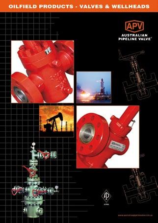
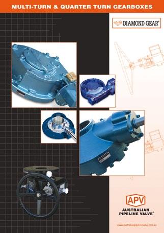
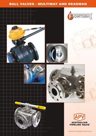
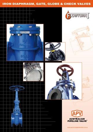
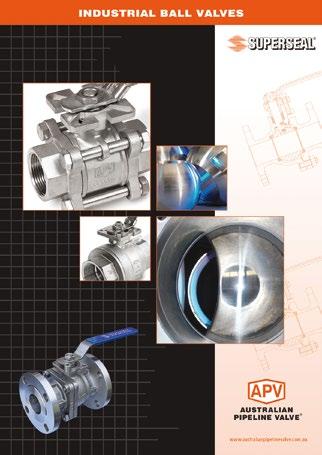
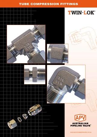
Oilfield Products Valves & Wellheads Gate, Globe & Check Valves - Forged Steel Plug Valves Lubricated, Sleeved & Lined Gate, Globe & Check Valves - Cast Steel Diamond Gear Gearboxes Flowturn Gate, Globe & Check Valves Flowturn Instrument Valves Flowturn Ball Valves Multiway & Deadman Flowturn Strainers & Sight Glasses Supercheck Wafer Check Valves Superseal Butterfly Valves Steamco Steam Valves Superseal Industrial Ball Valves TwinLok Tube Fittings Uniflo Check Valves
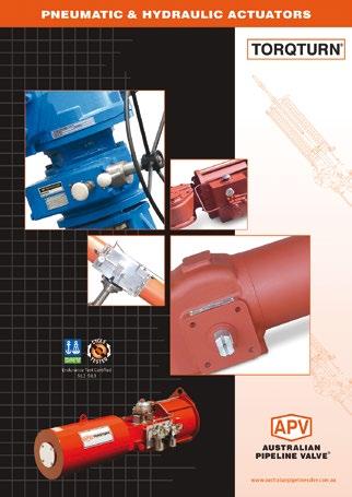
Actuators
Valves Floating & Trunnion Mounted Ball Valves Floating Small Bore Ball Valves Special Service Product Brochure Contact us for your local stockist/distributor
Torqturn
Ball


Introduction 2 Safety Information 3-4 1.0 Storage 4 1.1 Periodic maintenance during storage 4 2.0 Installation 5-6 3.0 General installation 6-9 4.0 Installation with flange welding 9 5.0 Operation 10 5.1 Manual operation 10 5.2 Lock device 10 5.3 Routine operation 10 6.0 Maintenance 11-14 6.1 Spare parts 12 6.2 Disassembly 13 6.3 Assembly 13-14 6.4 Ratchet lever mounting 14 6.5 Gearbox mounting 14 LINED BUTTERFLY VALVES - MODEL 2014 & 2016 SERIES INDEX Australian Pipeline Valve - Installation, Operation and Maintenance Manual 1 © Copyright Australian Pipeline Valve 1990 - 2024 Edition Catalogues, photos, brochures and technical publications are the exclusive property of Australian Pipeline Valve. Any unauthorised reproduction in total or in part, shall result in prosecution. Products and data sheets in this publication are subject to change at anytime without notice. Australian Pipeline Valve reserves the right to carry out amendments to products and materials.
INTRODUCTION
This manual describes the methods of installation and maintenance for lined butterfly valves.
The majority of this information is common knowledge to experienced steel valve users. When properly installed in applications for which they were designed, APV valves will give long trouble free service. This instruction is only a guide for installation, operation and minor maintenance. A professional APV approved valve engineering facility should be utilised for reconditioning and minor repairs.
We do recommend however that this entire document be read prior to proceeding with any installation or repair. Australian Pipeline Valve and it’s parent company take no responsibility for damage or injury to people, property or equipment. It is the sole responsibility of the user to ensure only specially trained valve repair experts perform repairs under the supervision of a qualified supervisor.
RESPONSIBILITY FOR VALVE APPLICATION
The User is responsible for ordering the correct valves. APV Valves are to be installed in the observance of the pressure rating and design temperature. Prior to installation, the valves and nameplates should be checked for proper identification to be sure the valve is of the proper type, material and is of a suitable pressure class and temperature limit to satisfy the applications requirements.
Do not use any valve in applications where either the pressure or temperature is higher than the allowable working values. Also valves should not be used in service media if not compatible with the valve material of construction, as this will cause chemical attacks.
RECEIVING INSPECTION AND HANDLING
Valves should be inspected upon receipt to determine:
- Compliance to purchase order requirements.
- Correct type, pressure class, size, body and trim materials and end connections (this information may be found on the nameplate or may be stamped on the body of the valve).
- Any damaged caused during shipping and handling to end connections, hand wheel or stem.
The End User is advised that misapplication of the product may result in injuries or property damage. A selection consistent with the particular performance requirements is important for proper application and is the sole responsibility of the end user.
LINED BUTTERFLY VALVES - MODEL 2014 & 2016 SERIES Australian Pipeline Valve - Installation, Operation and Maintenance Manual 2
Note
SAFETY INFORMATION
The following general safety notices supplement the specific warnings and cautions appearing elsewhere in this manual. They are recommended precautions that must be understood and applied during operation and maintenance of the equipment covered herein.
To avoid injury, never attempt disassembly while there are pressures either upstream or downstream. Even when replacing packing rings, caution is necessary to avoid possible injury. Disassemble with caution in the event all pressures are not relieved.

Note
To prevent valve distortion, inefficient operation, or early maintenance problems, support piping on each side of the valve.
• A valve is a pressurised device containing energised fluids and should be handled with appropriate care.
• Valve surface temperature may be dangerously too hot or too cold for skin contact.
• Upon disassembly, attention should be paid to the possibility of releasing dangerous and or ignitable accumulated fluids.
• Adequate ventilation should be available for service
APV refuses any liability for damage to people, property or plant as well as loss of production and loss of income under any circumstances but especially if caused by: Incorrect installation or utilisation of the valve or if the valve installed is not fit for intended purpose. It is the sole responsibility of the client to ensure the valve type and materials are correctly specified.
Australian Pipeline Valve - Installation, Operation and Maintenance Manual 3 LINED BUTTERFLY VALVES - MODEL 2014 & 2016 SERIES
DURING OPERATION BEAR IN MIND THE FOLLOWING WARNINGS:
a- The internal parts of valves (disc, stem, seat) shall be handled with care avoiding scratches or surface damage.
b- All tools and equipment for handling and supporting the internal parts shall be coated with soft materials.
c- Seat & seals can include Viton, EPDM, Buna & Teflon hence high temperatures will damage sealing components.
d- Never part open valve, or part close valve must be fully open of fully closed else seats will be damaged. If valves are used to throttle it must be done at very low pressures and for very short periods. As a result of constant throttling, the life of the valve will be shortened. Even then do not throttle unless clean fluids, less than 30% open or more than 70% closed, or venturi action will still cause immediate seat damage.
For all operations make reference to position number on part list of the applicable as-built drawing (an indicative drawing is shown in Figure 11 & 12). This is a general drawing only, for more accuracy refer to the as built drawings supplied with the order.
1.0 STORAGE
a- If storage in the field for a long time before installation is necessary, it is suggested to put valves in a dry and/or covered place. In this case the packaging and end covers integrity is especially important.
b- All the valves are supplied with special plastic ends to cover and protect the internal parts. We recommend you do not remove them during storage period.
c- Valves should be left in open position (unless actuated and set fail closed).
1.1 PERIODIC MAINTENANCE DURING STORAGE
In case of extended storage, the valves must be inspected and maintained as follows:-
• External surfaces must be inspected to ensure no damage to flange faces, paint finish etc.
• Without any disc movement, the internal surface of the valves must be inspected to check the complete absence of dust, rust and foreign matters.
• After cleaning and lubrication the disc must be operated (close/open complete stroke).
• The disc must be kept in the full open position.
• The end of the valve must be protected using the same end covers.
• Touch up any surface paint loss as required. If stored in a salt air environment then keep in sealed bags.
• Lined valves do not always have an indefinite shelf life. Dry, hot climates and moisture can all effect valve’s workings and even the liner itself. Without periodic use it is also possible some deformation could occur.
Australian Pipeline Valve - Installation, Operation and Maintenance Manual 4 LINED BUTTERFLY VALVES - MODEL 2014 & 2016 SERIES
2.0 INSTALLATION
The following procedure is required to be followed for correct installation.
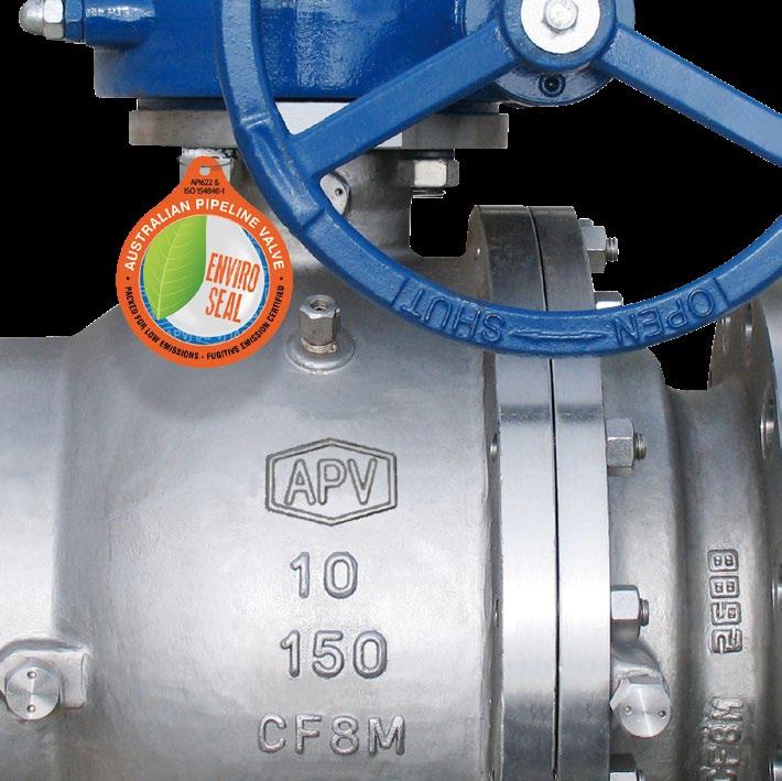
1. Before installation confirm the correct marking (rating, size and material) on the valve body and nameplate. Ensuring the valve is suitable for service in which it is being used. The direction of installing the butterfly valves is normally bi-directional unless marked with an arrow.
2. Body bolts and nuts on valve shall be checked and re-tightened if necessary in case loosened during installation.
3. Remove valve end protector and ensure gasket face is free from damage. Tighten all bolts between mating flanges and valve equally paying careful attention to properly tighten bolts. Ensure you rotate tightening procedure (opposing bolts sequently) gradually increasing torque.
4. Prior to installation of valve, satisfactory flushing shall be done to pipe to remove debris as soft seated butterfly valves are easily damaged.
5. Valves will operate at any angle horizontally or vertically.
6. This butterfly valve is bi-directional and may be installed in either direction.
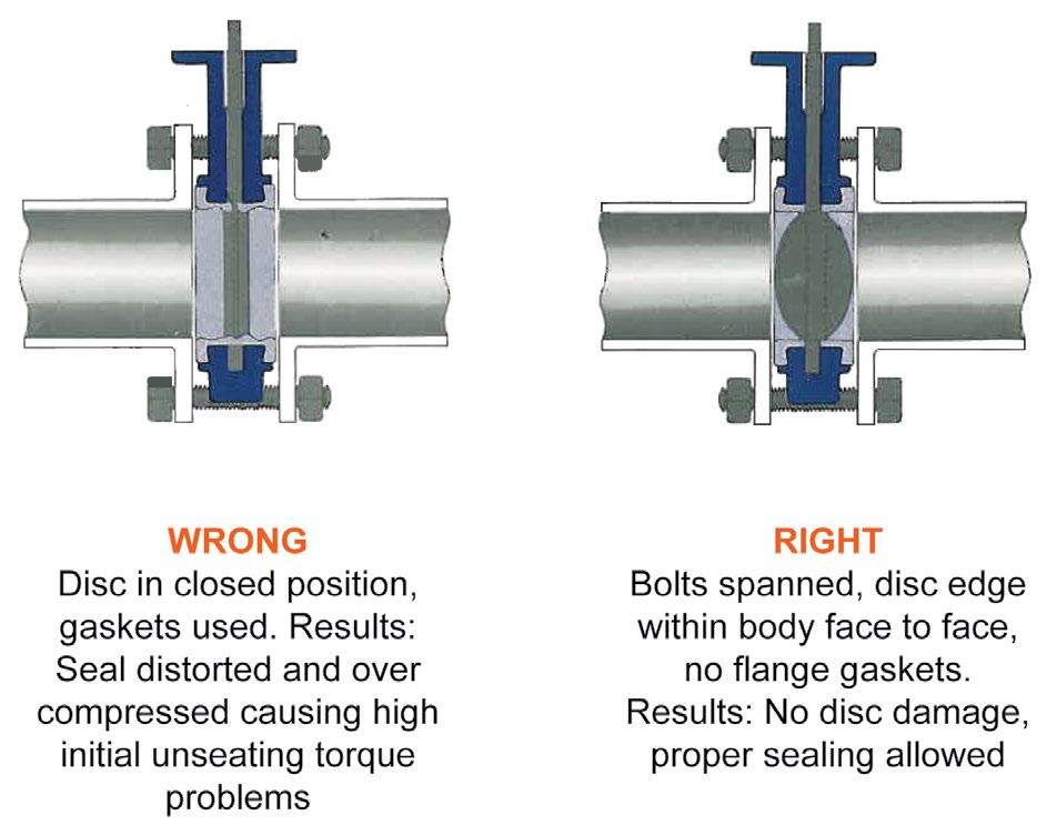
7. Install this valve between any ANSI Class 125 or 150 flanges or any AS, BS, PN flange (provided the rating of the valve matches the service rating). Cast iron, bronze or steel flanges may be used provided they meet the pressure rating of the line. No flange gaskets are required as the liner acts as a gasket. Rigid liners like EPDM often have ribs or in-built integral O-ring profiles to aid flange sealing where required.
8. The stem can be installed in any position, but if a choice of stem positions exists, good practice dictates that the valve be installed with the stem horizontal. This will minimise liner wear by distributing stem and disc weight evenly.
9. Valves should be installed with the disc in the closed position. This will prevent damage to the disc sealing edge.
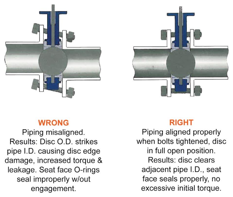
10. Before any flange bolts are tightened, valves should be centred (refer Figure 4 and 5) within the flanges and then carefully opened to assure free, unobstructed disc movement. Disc interference may result when valves are installed in pipelines having similar than normal inside diameters, such as heavy wall pipe, plastic lined pipe, or as cast flanges. Suitable corrective measures must be taken to remove these obstructions, such as taper boring the pipe or installing a spacer.
11. After proper operation has been verified, tighten all bolts using the crossover method. Recommended tightening torques pattern is as shown in Figure 7. Gradually tighten more on each revolution.
12. Prior to installing the valve, it is important to make sure the ID of the pipe and the pipe flanges are large enough to allow the disc edge to swing into the opening without interference. Damage to the disc edge can severely affect the performance of the valve.
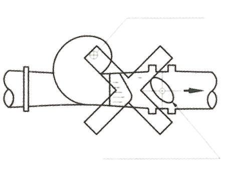
Interference may also occur when butterfly valves are bolted directly to the outlet flange of a swing check, silent check, or reducing flange. Check valve and butterfly valve combinations are very popular; normally a short spool piece may be required so the disc will not be obstructed by adjoining valve bores or mechanisms.
Australian Pipeline Valve - Installation, Operation and Maintenance Manual 5 LINED BUTTERFLY VALVES - MODEL 2014 & 2016 SERIES Note
Lined valves are not recommended for steam service or for service where a firesafe valve is required.
Do not install EPDM liner in compressed air lines or in lines containing any hydrocarbons. Viton liners are not recommended for hot water.
13. Lever-lock handles are not recommended for use on 200 NB (8”) and larger valves unless very low pressures.
3.0 GENERAL INSTALLATION
1. Make sure the pipeline and pipe flange faces are clean. Any foreign material such as pipe scale, metal chips, welding slag, welding rods, etc., can obstruct disc movement or damage the disc or seat.
2. Elastomer seats often have integral moulded O-ring ribs on the face of the seat (where required in harder compunds). As a result, no gaskets are required as these O-ribs serve the function of a gasket. Softer rubber compounds do not have integral moulded O-rings but do not require them due to the pressure rating of valve.
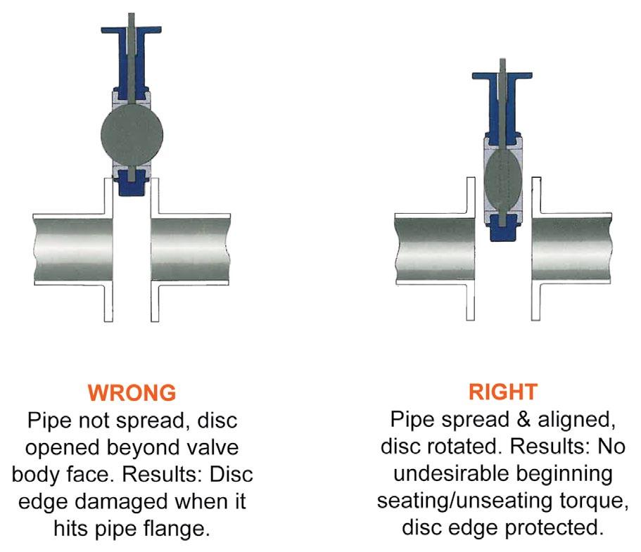
3. Align the piping and then spread the pipe flanges a distance apart so as to permit the valve body to be easily dropped between the flanges without contacting the pipe flanges (see Figure 4).
4. Check to see that the valve disc has been positioned to a partially open position with the disc edge about 6.3 mm to 9.5 mm from the face of the seat, approximately 10° open (see Figure 4).
5. Insert the valve between the flanges as shown below, taking care not to damage the seat faces. Always pick the valve up by the locating holes or by using a nylon sling on the neck of the body. Never pick up the valve by the actuator or operator mounted on the top of the valve.
6. Place the valve between the flanges, centre it, and then span the valve body with all flange bolts, but do not tighten the bolts, Carefully open the disc to the full open position, making sure the disc does not hit the adjacent pipe I.D. Now systematically remove jack bolts or other flange spreaders and hand tighten the flange bolts as shown in Figure 7. Very slowly close the valve disc to ensure disc edge clearance from adjacent pipe flange I.D. now open the disc to full open and tighten all flange bolts per specification as shown in Figure 6. Finally, repeat a full close to full open rotation of the disc to ensure proper.
7. 2014 and 2016 series butterfly valves are bi-directional.
8. Superseal butterfly valves are designed to operate between two flanges. For ‘dead end service’ a lugged style valve is recommended. The valve should still be placed between two flanges, except the end flange should be an open flange not a blind. Otherwise a special dead end service design valve is required.
Australian Pipeline Valve - Installation, Operation and Maintenance Manual 6 LINED BUTTERFLY VALVES - MODEL 2014 & 2016 SERIES
9. The Superseal valve disc can rotate 360° without damaging the valve or elastomer seat. The valve is designed to open with either clockwise or counter clockwise rotation of the shaft.
10. To prevent damage to the disc and seat during installation, the valve disc should be slightly open but not extending beyond the valve liner face. Positioning the disc in this ‘almost closed’ position will reduce seat interference and initial torque build-up during valve installation.
11. In general, it is preferable to install valves with the shaft in a horizontal orientation. In this position, shaft and disc weights are evenly distributed, minimising seat wear. Additionally, any foreign matter which may accumulate at the bottom of the disc and shaft is effectively removed each time the valve is opened.


Australian Pipeline Valve - Installation, Operation and Maintenance Manual 7
BUTTERFLY VALVES - MODEL 2014 & 2016 SERIES
LINED
1) Bend
2) Tee
3) Pipe Reducer
1)
Centrifugal pump sh horizontal and stem vertic
2)
Centrifugal pump shaf vertical and stem
3)
Axial pump shaf vertical and stem vert
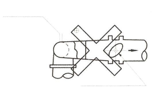
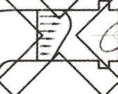
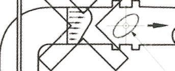
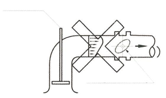
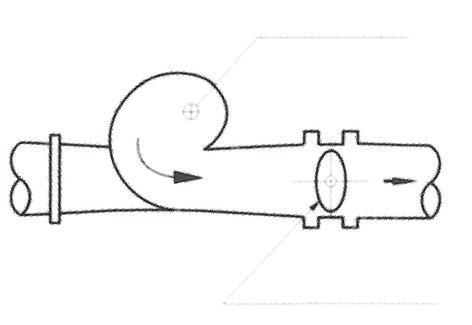
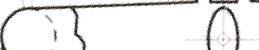
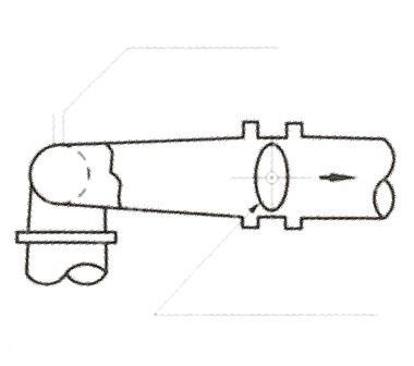
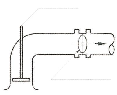
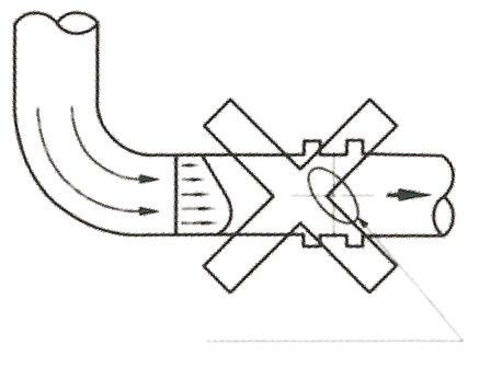
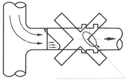
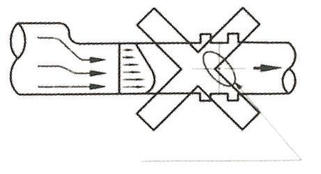
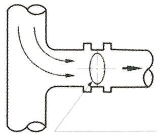
FIGURE 3b. BUTTERFLY VALVES LOCATED DOWN-STREAM NEAR A BEND, REDUCER, OR TEE SHOULD BE ORIENTATED AS FOLLOWS:
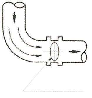
1) Bend
2) Tee
3) Pipe Reducer
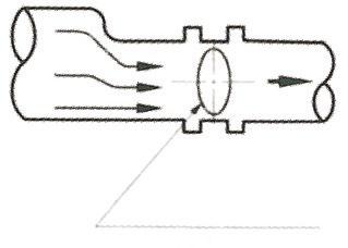
1) Centrifugal pump sh horizontal and stem vertic
2) Centrifugal pump shaf vertical and stem
3) Axial pump shaf vertical and stem vert
FIGURE 3a. BUTTERFLY VALVES LOCATED DOWN-STREAM NEAR THE DISCHARGE OF A PUMP SHOULD BE ORIENTATED AS FOLLOWS:
Australian Pipeline Valve - Installation, Operation and Maintenance Manual 8
BUTTERFLY VALVES - MODEL 2014 & 2016 SERIES
LINED
FIGURE 4 - INSERT BUTTERFLY VALVE BETWEEN FLANGES
FIGURE 5 - INITIAL CENTERING & FLANGING OF VALVE
FIGURE 6 - FINAL ALIGNING & TIGHTENING OF FLANGE BOLTS

Do not exceed double the torques shown for 50 NB to 300 NB. For 350 NB to 400 NB do not exceed more than torques shown by more than 50%. Bolting torques can vary. We recommend bolts are pregreased to increase strength and life. The above torques are minimum torques. The profile and resilience of the liner will effect the torque. Only use high tensile bolts.
4.0 INSTALLATION WITH FLANGE WELDING
When butterfly valves are to be installed between welding type flanges care should be taken to abide by the following procedure to ensure no damage will occur to the soft seat. To ensure no damage to the seat, insert the valve between the flanges after welding.
1. Place the valve between the flanges with the flange bores and valve body aligned properly. The disc should be in the 10° open position.
2. Span the body with the bolts.
3. Take this assembly of the flange-body-flange and align it properly to the pipe.
4. Tack weld the cut off flanges to the pipe.
5. Weld the flanges.
6. Install the valve once flanges have cooled.
Australian Pipeline Valve - Installation, Operation and Maintenance Manual 9 LINED BUTTERFLY VALVES - MODEL 2014 & 2016 SERIES Flange Size Recommended Min. Bolt Torque Flange Size Recommended Min. Bolt Torque 50 - 100 NB (2 - 4") 27.1 - 40.6 NM (20 - 30 ft·lbs.) 350 - 400 NB (14 - 16") 189.8 - 271.1 NM (140 - 200 ft·lbs.) 150 - 200 NB (6 - 8") 44.7 - 67.7 NM (33 - 50 ft·lbs.) 450 - 500 NB (18 - 20") 203.3 - 248.7 NM (150 - 210 ft·lbs.) 250 NB (10") 71.8 - 101.6 NM (53 - 75 ft·lbs.) 600 - 750 NB (24 - 30") 291.5 - 406.7 NM (215 - 300 ft lbs.) 300 NB (12") 108.4 - 149.1 NM (80 - 110 ft·lbs.) 900 NB (36") 406.7 - 508.4 NM (300 - 375 ft lbs.) MINIMUM RECOMMENDED BOLTING TORQUE FIGURE 8 - MINIMUM RECOMMENDED BOLTING TORQUE 1 7 4 5 3
26 FIGURE 7 - RECOMMENDED BOLT TIGHTENING SEQUENCES
8
Example only, same, criss-cross pattern applies for all bolting patterns.
5.0 OPERATION
5.1 MANUAL OPERATION
Valve adjustments is by clockwise turning of the stem. Lever operated and gear operated valves have a position indicator to indicate open or closed (see Figure 9 & 10). Butterfly valves are not designed to be used for throttling. Do not leave part open, or seats will be damaged. Valves must be full open or full closed. If valves are used to throttle it must be done at very low pressures and for very short periods. As a result of constant throttling, the life of the valve will be shortened. Even then do not throttle unless clean fluids, less than 30% open or more than 70% closed, or venturi action will still cause immediate seat damage.
5.2 LOCK DEVICE
Where provided (optional) the valve has a locking hole that allows valve to be locked in full open or full closed position.
5.3 ROUTINE OPERATION
It is recommended that the valve be periodically at least partially stroked to ensure the valve functions and will prevent seizure/galvanisation of any mating stem chamber or seat surfaces or memory moulding of the seat. This especially applies to automatic actuated valves which only have a limited amount of torque available to function the valve. Duration depends on service, criticality, etc. However, it also must be factored in that if there are impurities or particulates in the line each operation could reduce seat life proportionately.
Packing leakage could result in personal injury. Valve packing is tightened prior to shipping but may require adjustment to meet specific service conditions.
Australian Pipeline Valve - Installation, Operation and Maintenance Manual 10 LINED BUTTERFLY VALVES - MODEL 2014 & 2016 SERIES
FIGURE 9 FIGURE 10
Personal injury may result from sudden release of any process pressure. APV recommends the use of protective clothing, gloves and eye wear when performing any installation or maintenance.
Isolate the valve from the system and relieve pressure prior to performing maintenance.
Disconnect any operating lines providing air pressure, control signals or electrical power to actuators.

6.0 MAINTENANCE
Valves should be periodically checked. Frequently depends on service, critically and frequently of use. Various design configurations are produced within the 2014 and 2016 range. Most are single piece body. Valves with liners like solid PTFE use a 2 piece bolted body.
The following periodic preventative maintenance practises are recommended for all Superseal butterfly valves.
1. Operate the valve from full open to full closed to assure operability.
2. Check flange bolting for evidence of loosening and correct as needed.
3. Inspect the valve and surrounding area for previous or existing leakage at flange faces or shaft connections.
4. Check piping and/or wiring to actuators and related equipment for looseness and correct as needed.
Australian Pipeline Valve - Installation, Operation and Maintenance Manual 11 LINED BUTTERFLY VALVES - MODEL 2014 & 2016 SERIES
MATERIALS
1. Body
2. Disc
Cast iron, stainless ductile iron, aluminium, carbon steel, stainless steel, etc.
316SS, 304SS, ALBronze, hard epoxy coated, hard rubber coated, nickel plated, PTFE coated, 410SS, etc.
3. Stem 316SS, 304SS, PTFE coated, AL-Bronze cl
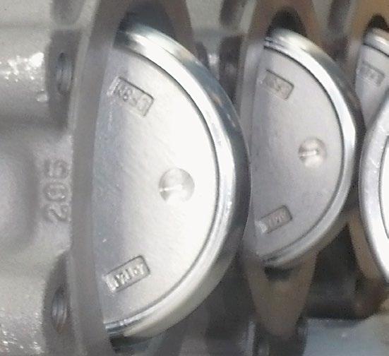
4. Seat*
NBR (90º - 100ºC), EPDM (90ºC) teflon, food grade rubber, Buna-N, Viton, Hypalon, etc.
5. Retaining Pin/ Gland Ring 304SS/316SS/410SS
6. Bottom Bushing Bronze/Nylon
7. O-Rings NBR (nitrile)/EPDM
8. Upper Bush Delrin/Nylon/Bronze *Optional backing seal required on some solid and high pressure seats
LINED BUTTERFLY VALVES - MODEL 2014 &
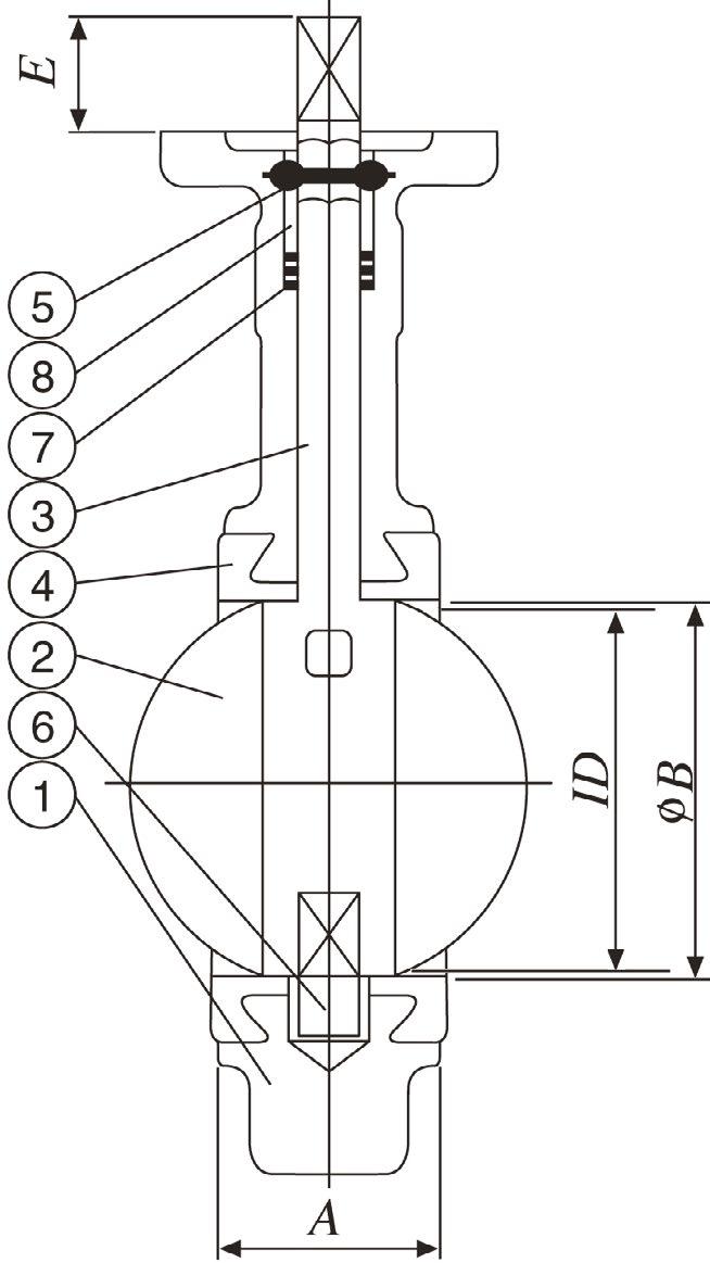
This is a general drawing only, design will vary depending on size, class, trim, etc. Refer to as-built drawing.
Check the packing box for pressurised process fluids even after the valve has been removed from the pipeline, particularly when removing packing hardware or packing rings, or removing packing box pipe plug. Do not attempt to change the stem seals while the valve is in-line, it is not possible or allowable.
If a gasket seal is disturbed while removing a adjusting gasketed parts, APV recommends installing a new gasket while reassembling. A proper seal is required to ensure optimum operation.
6.1 SPARE PARTS
All gear operators are lubricated for life at assembly and should not require service. In the event of a gear operator suffering damage or excessive wear, it is suggested that the complete gear operator be replaced. Only the handwheel, pin/cover, and some adaptor bushings are available for repair parts. If under 350 NB (14”) it is usually just as cheap to replace the whole valve as it is to repair it unless the valve is a special specification like stainless body. See the sample bill of material shown above. Replacement rubber liners and stem seal kits are available.
Australian Pipeline Valve - Installation, Operation and Maintenance Manual 12
2016 SERIES
FIGURE 11
4*
6.2 DISASSEMBLY
Single piece body design disassembly as follows.
a. Lay down the valve with the disc in the closed position.
b. Loosen the taper pin(s) from the valve disc using a punch. The punch should be same size or larger diameter as small end of taper pin to avoid flattening the taper pin.
c. Remove taper pin(s) from disc. Remove the valve shaft from the body (using a twisting motion will assist removal).
d. Remove the valve disc from body making sure not to damage the disc or seat sealing edge.
e. The seat can be removed from either direction by applying even pressure on one face to push the seat out of the body. If the valve is of dead end service design, remove set screws around periphery of body extending into seat prior to seat removal. Some liners also have an elastomer, monolithic or silicon seat backing ring.
f. Remove shaft bushings from body as required.
Note: Some valve designs use a pinless disc which requires the shaft is first pulled out before disc removal, consult as-built drawing.
2 Piece body design requires that the 2 body sections are first unbolted and then the procedure is similar to 6.2 above.
6.3 ASSEMBLY
Reassemble the valve as follows.
a. Thoroughly clean all parts. Inspect components for any defects.
b. Apply small amount of silicon grease to the inside surfaces of the body, including the lower and upper shaft holes.
c. Insert the shaft bushings into the body being careful not to allow intrusion into the body seat bore.
d. Install the seat into the centre of the body, making sure the shaft holes in the seat line up with the holes in the body.
e. Completely coat the inside surfaces of the seat with silicon grease. Carefully push the disc into the seat in the open position (90 degrees to the body). Line up the shaft holes of the disc as close as possible with the shaft holes in the seat body.
f. Insert the shaft through the body and disc, use a twisting motion to align the keyway parallel with the disc.
g. Insert taper pin(s) into the disc and set with two or three sharp blows. Wipe dust shield O-ring with silicon grease and place over the shaft into the top of the body.
h. If the valve is of dead end service design, insert set screws through the body into the seat.
Australian Pipeline Valve - Installation, Operation and Maintenance Manual 13
LINED BUTTERFLY VALVES - MODEL 2014 & 2016 SERIES
6.4 RATCHET LEVER MOUNTING
a. Position the disc in the closed position.
b. Install the ratchet notch plate using machine bolts, nuts and lock washers, but do not tighten the fasteners.
c. Install the drive key in the shaft (where applicable). Tap the key into place to ensure it is fully seated in the keyway.
d. Install the handle so that it is parallel with the disc face. The locking lever must be fully retracted before it will pass through the ratchet plate. Tighten the set screw in the handle against the key.
e. With the handle installed flush with the ratchet plate, engage the locking lever with the ratchet plate. Using the handle, adjust the position of the ratchet plate until the disc face is parallel with the valve face, then tighten the fasteners securely.
6.5 GEARBOX MOUNTING
a. Position the disc in the closed position.
b. Install the drive key in the shaft (where applicable). Tap the key into place to ensure it is fully seated.
c. Rotate the gear shaft to the full clockwise position. Align the keyway in the gearbox bore with the key in the shaft and slide the gearbox onto the shaft.
d. Fasten the gearbox to the mounting bracket with the appropriate machine bolts and lock washers. It may be necessary to rotate the gear shaft slightly to align the mounting holes in the gear with the plate.
e. Adjust the stops in the gearbox to position the face of the disc parallel with the face of the valve in the closed position and perpendicular to the face of the valve in the open position.
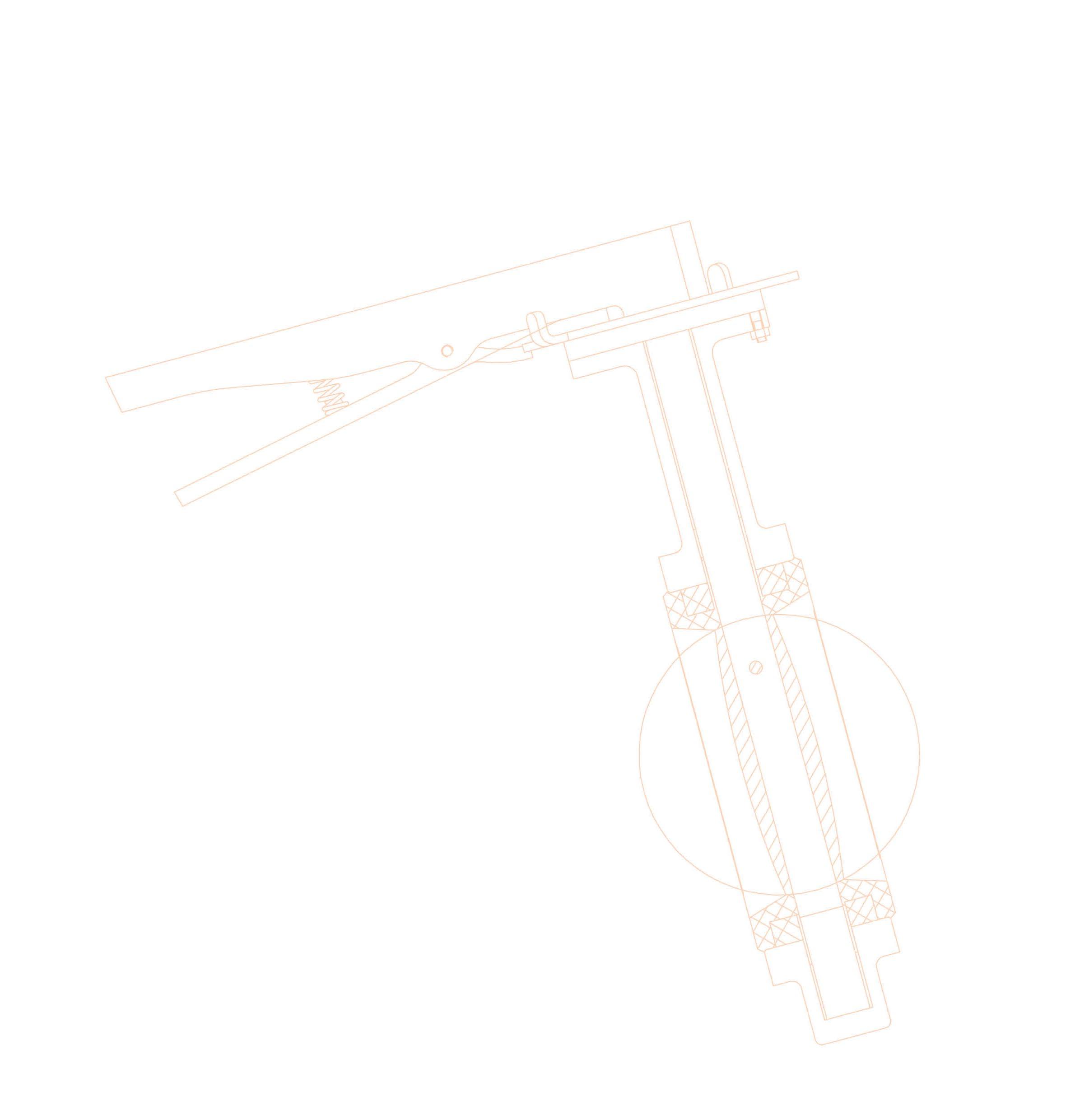
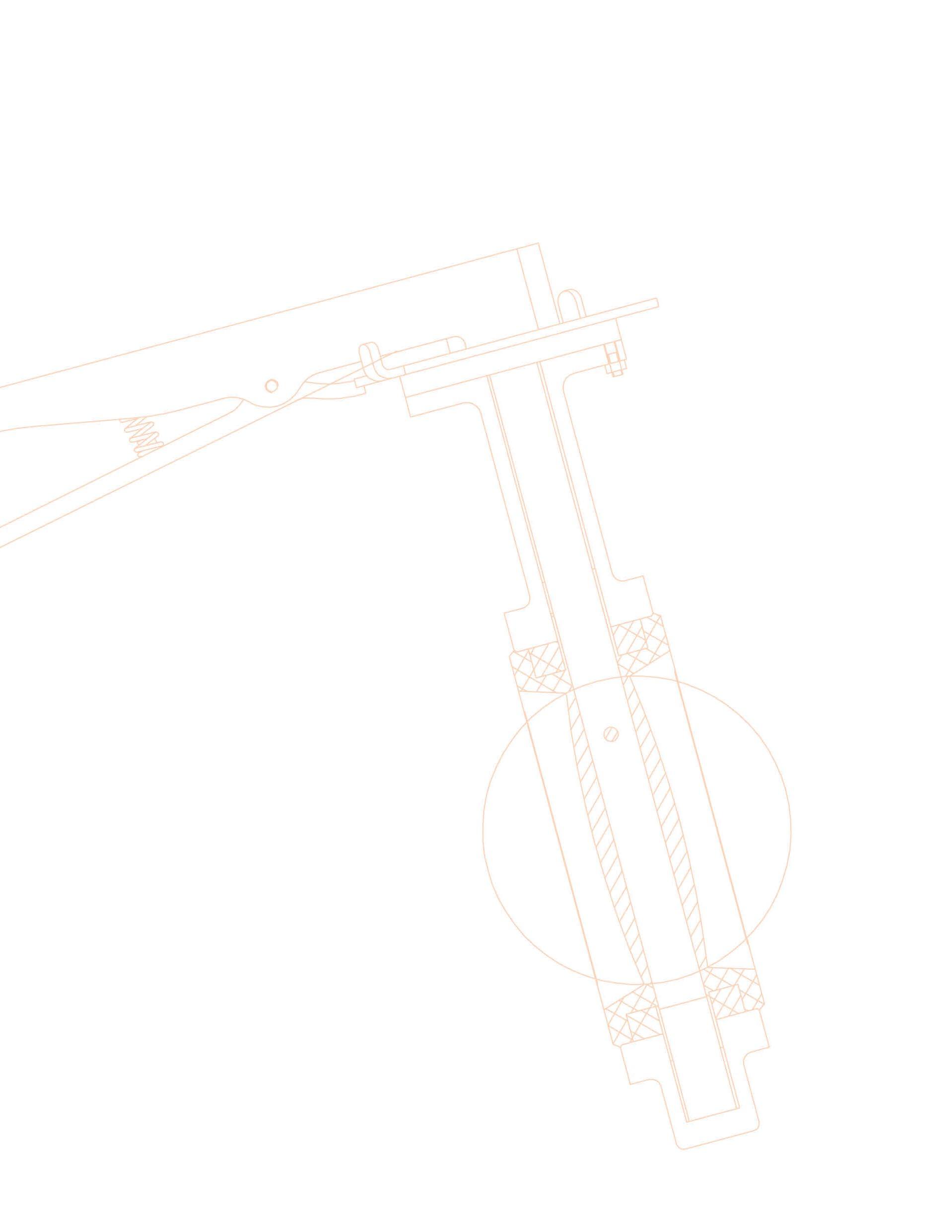
Australian Pipeline Valve - Installation, Operation and Maintenance Manual 14 LINED BUTTERFLY VALVES - MODEL 2014 & 2016 SERIES FIGURE 12
Indicative explosion only. Pinned disc example shown. Refer to as-built drawing for actual parts list.
NOTES Australian Pipeline Valve - Installation, Operation and Maintenance Manual 15
Australian Pipeline Valve - Installation, Operation and Maintenance Manual 16 NOTES
Australian Pipeline Valve - Installation, Operation and Maintenance Manual 17 NOTES

www.australianpipelinevalve.com.au AUSTRALIAN PIPELINE VALVE® HEAD OFFICE 70-78 Stanbel Road Salisbury Plain South Australia 5109 Telephone +61 (0)8 8285 0033 email: admin@australianpipelinevalve.com.au If you have any requirements in the field of valves, please contact us for a prompt response. Continuous development of Australian Pipeline Valve products may necessitate changes in the design or manufacture process. Australian Pipeline Valve reserves the right to effect any such changes without prior notice. © Australian Pipeline Valve 1990 - 2024 Edition LOCAL DISTRIBUTOR/AGENT IOM Superseal Butterfly Lined
