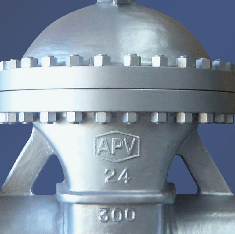
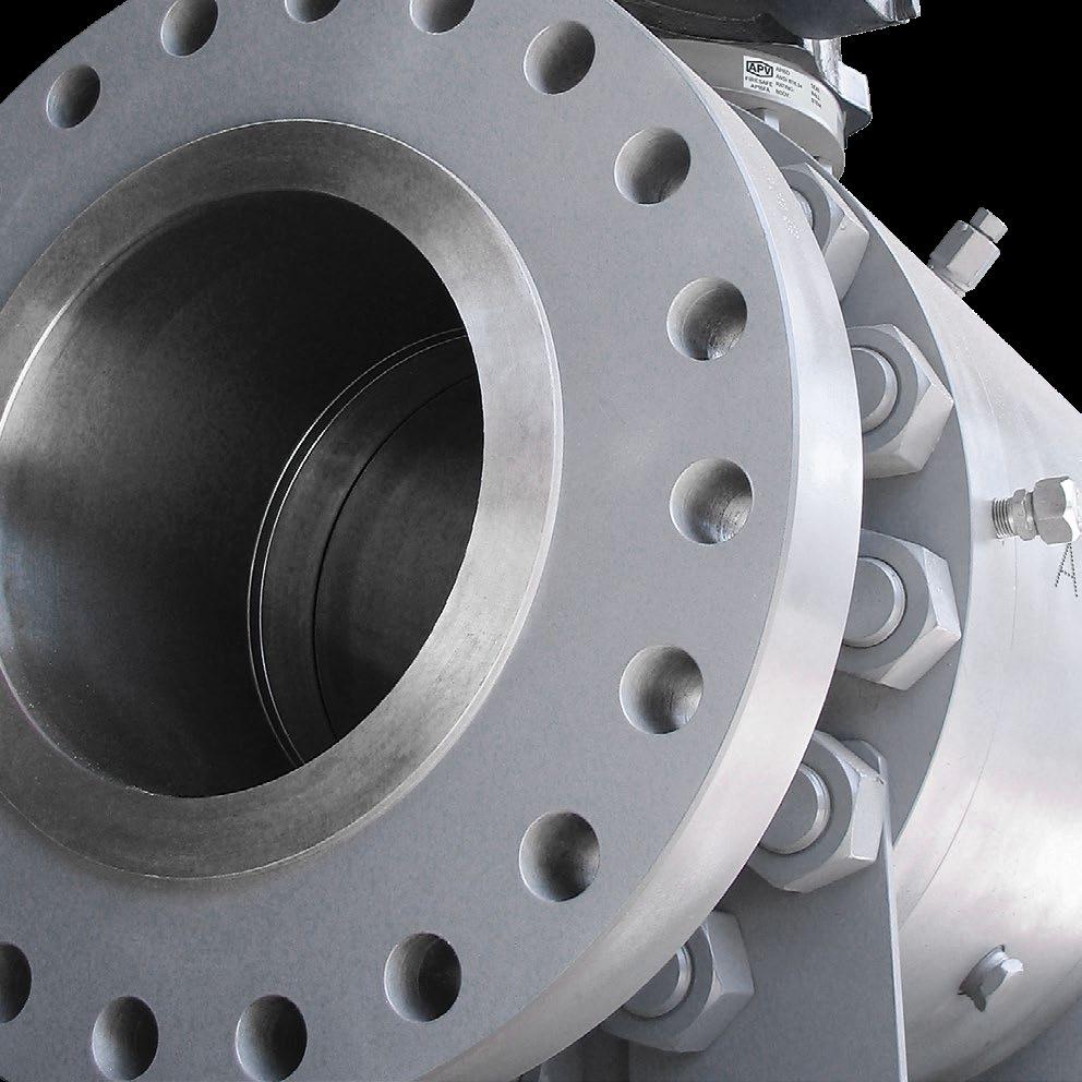
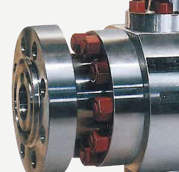
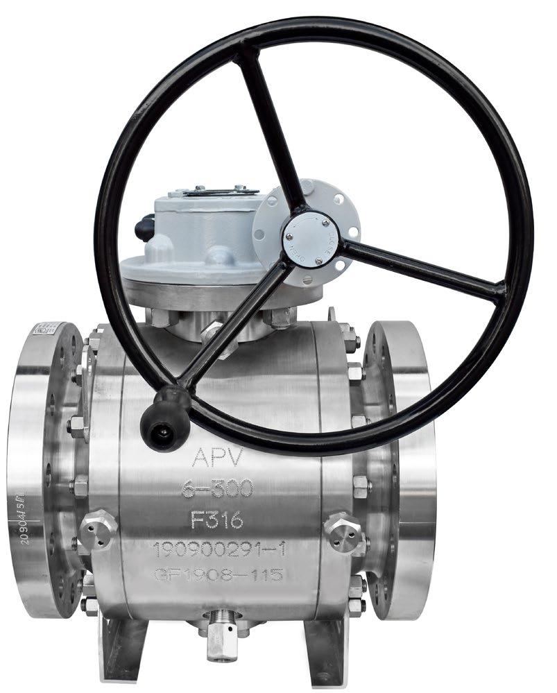
SIDE ENTRY 3 PIECE
TRUNNION BALL VALVES
API6D STANDARD
BVF100 SERIES
www.australianpipelinevalve.com.au INSTALLATION, OPERATION & MAINTENANCE MANUAL
COMPLETE PRODUCT LINE
“Australian Pipeline Valve produces isolation, control and flow reversal protection products for severe and critical service media in utility, steam, pipelines, oil & gas and process industries. APV valves and pipeline products form the most competitive portfolio in the market.”
View our catalogues at www.australianpipelinevalve.com.au AUSTRALIAN PIPELINE VALVE BRAND RANGE - CATALOGUES APV FAMILY OF BRANDS RANGE - CATALOGUES
Oilfield Products Valves & Wellheads Gate, Globe & Check Valves - Forged Steel Plug Valves Lubricated, Sleeved & Lined Gate, Globe & Check Valves - Cast Steel Diamond Gear Gearboxes Flowturn Gate, Globe & Check Valves Flowturn Instrument Valves Flowturn Ball Valves Multiway & Deadman Flowturn Strainers & Sight Glasses Supercheck Wafer Check Valves Superseal Butterfly Valves Steamco Steam Valves Superseal Industrial Ball Valves TwinLok Tube Fittings Uniflo Check Valves
Actuators
Valves Floating & Trunnion Mounted Ball Valves Floating Small Bore Ball Valves Special Service Product Brochure Contact us for your local stockist/distributor
Torqturn
Ball
Australian Pipeline Valve - Installation, Operation and Maintenance Manual 1 SIDE ENTRY 3P TRUNNION BALL VALVES API6D STANDARD - BVF100 SERIES Introduction 4-5 Safety Information 6-7 1.0 Preservation And Storage 7-8 1.1 Storage 7 1.2 Periodic maintenance during storage 7-8 1.3 Environmental consideration 8 2.0 Installation 8-13 2.1 Valve preparation 8 2.2 Valve installation 8-9 2.3 Maintenance prior to flushing 10 2.4 Flushing the pipeline 10-11 2.5 Maintenance post flushing 11-12 2.6 Commissioning 12-13 3.0 Valve Removal From Line 13 4.0 Gearbox Removal 14 5.0 Valve Disassembly 14-15 5.1 Body 14 5.2 Bonnet and stem removal 14-15 5.3 Ball removal 15 5.4 Seat and spring removal 15 6.0 Inspection And Repairs 15-17 6.1 Body and bonnet 15 6.2 Seat and seat housing 15 INDEX
Australian Pipeline Valve - Installation, Operation and Maintenance Manual 2 SIDE ENTRY 3P TRUNNION BALL VALVES API6D STANDARD - BVF100 SERIES 6.3 Soft seat insert (only for valve with soft seat insert) 16 6.4 Seals 16 6.5 Spring 16 6.6 Bearings 16 6.7 Ball 16 6.8 Steam seal and stem 16 6.9 Bolts, nuts and threaded components 16 7.0 Valve Assembly 17-18 7.1 Valve lubrication 17 7.2 Seat and spring assembly 17 7.3 First adaptor assembly 17 7.4 Ball, support, bonnet and stem assembly 17 7.5 Second adaptor assembly 18 7.6 Gearbox mounting to valve 18 7.7 Pressure Test 18 8.0 Operation And Maintenance Instructions 18-22 8.1 Operation instruction 18-19 8.2 Lubrication 19 8.3 Valve operating 19-20 8.4 Maintenance schedule 20-21 8.5 Double block-and-bleed 21-22 9.0 Automatic Over Pressure Relief 23 10.0 Overview Design Features 24 Appendix 1 - Typical Bill of Materials 25-27 Appendix 2 - Bolting torques 28-29

Australian Pipeline Valve - Installation, Operation and Maintenance Manual 3 SIDE ENTRY 3P TRUNNION BALL VALVES API6D STANDARD - BVF100 SERIES Appendix 3 - Label details 30 Appendix 4 - Design features 31-32 Warranty 33 © Copyright Australian Pipeline Valve 1990 - 2024 Edition Catalogues, photos, brochures and technical publications are the exclusive property of Australian Pipeline Valve. Any unauthorised reproduction in total or in part, shall result in prosecution. Products and data sheets in this publication are subject to change at anytime without notice. Australian Pipeline Valve reserves the right to carry out amendments to products and materials.
The majority of this information is common knowledge to experienced steel valve users. When properly installed in applications for which they were designed, APV valves will give long trouble free service. This instruction is only a guide for installation, operation and minor maintenance. A professional APV approved valve engineering facility should be utilised for reconditioning and minor repairs. Note
We do recommend that this entire document be read prior to proceeding with any installation or repair. Australian Pipeline Valve and it’s parent company take no responsibility for damage or injury to people, property or equipment. It is the sole responsibility of the user to ensure only specially trained valve repair experts perform repairs under the supervision of a qualified supervisor.
RESPONSIBILITY FOR VALVE APPLICATION
The User is responsible for ordering the correct valves. APV Valves are to be installed in the observance of the pressure rating and design temperature. Prior to installation, the valves and nameplates should be checked for proper identification to be sure the valve is of the proper type, material and is of a suitable pressure class and temperature limit to satisfy the applications requirements.
Do not use any valve in applications where either the pressure or temperature is higher than the allowable working values. Also valves should not be used in service media if not compatible with the valve material of construction, as this will cause chemical attacks.
RECEIVING INSPECTION AND HANDLING
Valves should be inspected upon receipt to determine:
- Compliance to purchase order requirements.
- Correct type, pressure class, size, body and trim materials and end connections (this information may be found on the nameplate or may be stamped on the body of the valve).
- Any damaged caused during shipping and handling to end connections, hand wheel or stem.
The End User is advised that misapplication of the valve may result in injuries or property damage. A selection consistent with the particular performance requirements is important for proper application and is the sole responsibility of the end user.
Australian Pipeline Valve - Installation, Operation and Maintenance Manual 4 SIDE ENTRY 3P TRUNNION BALL VALVES API6D STANDARD - BVF100 SERIES
INTRODUCTION
CONSIDERATIONS OF TECHNICAL RISK/ LIMIT OF LIABILITY TO CLIENT FOR BALL VALVES
Australian Pipeline Valve don’t consider in our design the following factors of risk:
1. Australian Pipeline Valve ‘Standard’ ball valves can be used in a temperature range between -28.8 to +200°C. (Note, pressure limitations apply above 38°C refer to Pressure/Temperature charts.) For service temperatures below -28.8°C ball valve construction materials shall be submitted to an impact test at the minimum service temperature. For temperatures outside of the range of -28.8°C to +200°C ball valves have to be provided with seats, seals and body material able to withstand the temperature degree required.
2. The onus is on the customer to specify all materials of construction and service conditions. Australian Pipeline Valve shall assume standard materials and conditions if not otherwise specified.
3. Australian Pipeline Valve ‘Standard’ ball valves are not equipped with devices suitable to avoid internal over-pressures caused by incorrect operations of process or by-fluids & liquids subjected to an increase of volume and/or pressure (these devices, such as the over-pressure hole in the ball or safety seats are available upon request).
4. Australian Pipeline Valve ‘Standard’ ball valves are not designed with special devices to withstand a sudden thermal jump (thermal shock).
5. In general Australian Pipeline Valve ‘Standard’ ball valves are not mechanically designed to bear overloads due to exceptional atmospheric or natural phenomenon’s (such as earthquakes).
6. In general Australian Pipeline Valve ‘Standard’ ball valves are not designed to bear loads on flanges, on pipe connections or pipeline.
7. In general Australian Pipeline Valve ‘Standard’ ball valves can’t withstand ice inside their bodies (in this case user must specify the optional stem extension for insulating, avoiding the presence of residual product inside the valve).
8. Australian Pipeline Valve ‘Standard’ ball valves are not suitable for low temperature service below -29°C (-20°F) unless provided with cryogenic stem extension and other modifications (available on request).
9. Australian Pipeline Valve ‘Standard’ ball valves are suitable for ‘industrial’ oxygen (not medical) service when supplied degreased and packed in polyethylene bags only.
10. The compatibility between ball valves construction materials and medium is selected by the user. The user is ultimately responsible for verifying the compatibility between medium and materials.
11. Abrasive or dirty service, high temperature service, low temperature service, vacuum service, near zero pressure service and other special applications should be clearly stated when requesting quotation.
BALL VALVE START-UP
Before installing the ball valve onto the pipe-line it is mandatory for the user to verify the compatibility of the ball valve with service conditions (medium, temperature and pressure). With reference to standard ball valves held in stock the reseller and end user will have to assure themselves of the compatibility with the use of conditions required by the customer. Australian Pipeline Valve ball valves must be only used for on-off (fully open/fully closed) service.
Before using the ball valve in a potential explosive atmosphere it’s necessary: -
• To verify the compatibility between the ball valve and the zone in which the ball valve should be installed.
• To foresee the pipe-line ground condition on which the ball valve should be installed.
• To check that the temperature of the ball valve surface is not higher than the flammable point of the atmosphere in which the ball valve is installed (in this case specify an insulating cover device for the valve and an extension for the wrench)
• Before installing ball valves with welding ends to make sure that the process of welding is carried out in accordance with all the safety requirements of the classified zone.
• To avoid mechanical knocks during the installation that may cause sparks.
Australian Pipeline Valve cannot be held responsible for damage caused by use of the product especially if it is improper use or modified.
Australian Pipeline Valve - Installation, Operation and Maintenance Manual 5 SIDE ENTRY 3P TRUNNION BALL VALVES API6D STANDARD - BVF100 SERIES
SAFETY INFORMATION
The following general safety notices supplement the specific warnings and cautions appearing elsewhere in this manual. They are recommended precautions that must be understood and applied during operation and maintenance of the equipment covered herein. This manual provides instructions for storing, general servicing, installation and removal of ball valves.
Do not attempt to disassemble a valve while there is pressure in the line. Make sure both upstream and downstream pressures are removed. Disassemble with caution in the event all pressures are not relieved.
To prevent valve distortion, inefficient operation, or early maintenance problems, support piping on each side of the valve.
• A valve is a pressurised device containing energised fluids and should be handled with appropriate care.
• Valve surface temperature may be dangerously too hot or too cold for skin contact.
• Upon disassembly, attention should be paid to the possibility of releasing dangerous and or ignitable accumulated fluids.
• Adequate ventilation should be available for service
Do not use the ball valve in process conditions where the pressure, temperature, media and other technical conditions exceed the limitations set by the valve’s specifications. When handling fluids that could cause damage to human health, the environment or property, the necessary safety precautions to prevent risk must be taken.
APV and it’s resellers refuse any liability for damage to people, property or plant as well as loss of production and loss of income under any circumstances but especially if caused by: Incorrect installation or utilisation of the valve or if the valve installed is not fit for the intended purpose. It is the sole responsibility of the client to ensure the valve type and materials are correctly specified.
Australian Pipeline Valve - Installation, Operation and Maintenance Manual 6 SIDE ENTRY 3P TRUNNION BALL VALVES API6D STANDARD - BVF100 SERIES
DURING OPERATION BEAR IN MIND THE FOLLOWING WARNINGS:
a- The graphoil packing and body gasket is very brittle: any twisting or bending shall be avoided.
b- The internal parts of valves (ball, stem, seats) shall be handled with care avoiding scratches or surface damage.
c- All tools and equipment for handling and supporting internal critical sealing parts shall be coated with soft materials.
d- Seats & seals usually include Viton, Devlon, Nylon & Teflon, hence high temperatures and some chemicals will damage sealing components.
e- Never part open valve, valve must be fully open of fully closed or else the seats will be damaged. For all operations make reference to position number on part list of the applicable drawing. The drawing in the Appendix is a general drawing only, for more accuracy refer to the as-built drawings supplied with the order.
SCOPE OF INSTALLATION ACCORDING TO THE TYPE OF FLUID (DANGEROUS FOR THE ENVIRONMENT OR HUMAN HEALTH)
Group 1 Classification
- The incorporation of additional safety elements “Double packing” is recommended for the range of products included in Group 1.
- The use of valves without additional safety devices in Group 1 will be the responsibility of the user or the purchaser, as well as the advisability of installing leakage detection systems.
Group 2 Classification
- Carbon steel valves will not be used in corrosive fluid lines.
1.0 PRESERVATION & STORAGE
1.1 STORAGE
a- If storage in the field for a long time before installation is necessary, it is suggested to put valves in a dry and/or covered place. In this case the packaging and end covers integrity is especially important.
b- All the valves are supplied with special plastic ends to cover and protect the internal parts. We recommend you do not remove them during storage period.
c- Valves should be left in the open position (unless actuated and set fail closed).
1.2 PERIODIC MAINTENANCE DURING STORAGE
In case of extended storage, the valves must be inspected and maintained as follows:-
• External surfaces must be inspected to ensure no damage to flange faces, paint finish etc. In case of the presence of rust and/or damaged painting, the area must be cleaned by brushing, degreasing & repainting.
Australian Pipeline Valve - Installation, Operation and Maintenance Manual 7 SIDE ENTRY 3P TRUNNION BALL VALVES API6D STANDARD - BVF100 SERIES
• The protection must be restored following the instruction indicated from APV in accordance with the painting cycle used.
• Without any ball movement, the internal surface of the valves must be inspected to check the complete absence of dust, rust, foreign matters and the integrity of lubricant coat. If not satisfactory then clean and lubricate the internal part using a nebulised lubricant. Do not leave any lubricant on the seat itself or else the seat may attract debris which in turn could damage the seat.
• After cleaning and lubrication the ball must be operated (close/open complete stroke).
• The ball must be kept in the full open position during installation.
• The end of the valve must be protected using the same end covers.
• We recommend you tropicalise bore and ends of valves if stored in humid or salt air environment. Grease bore with valve full open so no grease is applied to soft seat inserts.
1.3 ENVIRONMENTAL CONSIDERATIONS
According to ISO 14000 regulations and the environmental policy of APV the recyclability of the components that form part of APV valves is as follows:
Recyclable components:
Metal parts, PTFE (hard), plastic plug (low-density polyethylene).
Non-recyclable components:
PTFE mixed with other compounds (glass-fiber, graphite, etc.), nylon, graphite and graphite mixed with metal.
2.0 INSTALLATION
2.1 VALVE PREPARATION
a- Remove the ends protectors and check accurately the status of the valve as indicated in point 1.2.
b- Prior to shipment, a preservative/corrosion inhibitor may have been applied to the inner body of the valve. This preservative/corrosion inhibitor can be removed with a solvent, provided the solvent used does not affect the seats/seals used in the valve.
c- Do not operate the valve until the following procedures have been fully applied:
• Clean internal conduits.
• After cleaning the ball must be operated (one complete stroke).
• During installation the ball must be kept in the fully open position.
2.2 VALVE INSTALLATION
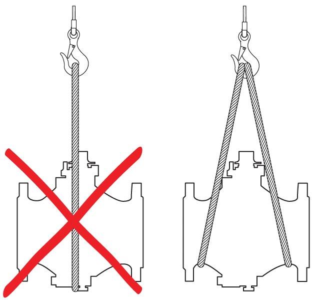
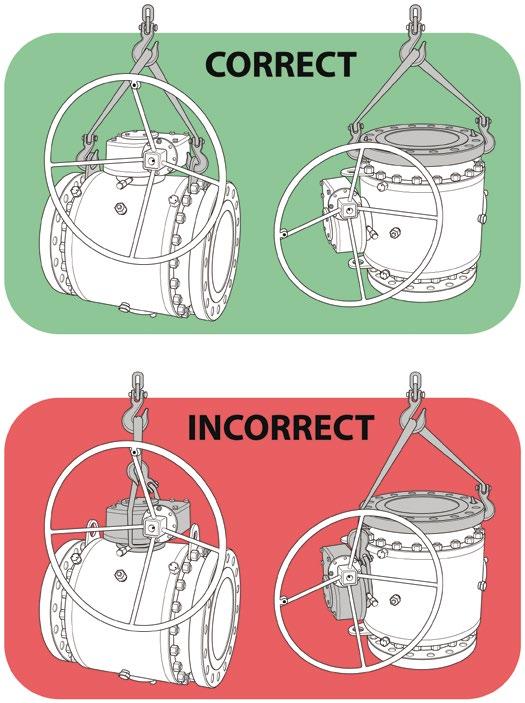
a- To handle the valve use body lugs if applicable or suitable eyebolts. Never handle the valve by yoke or using the lever or actuator or gear box eye bolts. Never lift from bore of valve. Do not lift the valve using only one lifting lug.
Australian Pipeline Valve - Installation, Operation and Maintenance Manual 8 SIDE ENTRY 3P TRUNNION BALL VALVES API6D STANDARD - BVF100 SERIES
b- The end protectors must be removed only immediately before installation. If one of end is not connected to the line for a period of longer than half a day the opened end shall be securely sealed with plastic or wooden cover.
c- For butt weld type valves take care for the following: If brushing or grinding, seal valve conduit (bore) to prevent damage. At the end of such operation clean accurately the conduit. The welding procedure and post-weld treatment shall be performed taking into account the allowable maximum temperature for seats and seals. The welding sequence shall be pre-planned in order to give an acceptable piping load to the valve. Leave valve in full open position to reduce temperature transmission to soft seats. For valves up to 80 NB (3”) use temperature measuring strips. Ensure temperature of body does not go above 180°C.
d- At the end of installation lock the valve full open in order to avoid any movement of the ball before flushing the pipeline.
e- Valves will operate at any angle horizontally or vertically, although it is recommended you install valves in a vertical position with stem pointing upwards for ease of operation, inspection and accessibility.
f- Ball valves are usually bi-directional, and therefore may be installed in either direction. In some cases, ball valves such as ‘metal to metal’ and low temperature valves may be unidirectional, in which case the direction of flow will be indicated on the valve body.
If the ball valve is equipped with a test connection port, make sure that it is fully closed before pressurising the valve.
Local safety regulations must be complied with for transport to the place of installation. Make sure that the valves cannot tilt or slip in any way (see figure below).
Australian Pipeline Valve - Installation, Operation and Maintenance Manual 9 SIDE ENTRY 3P TRUNNION BALL VALVES API6D STANDARD - BVF100 SERIES
2.3 MAINTENANCE PRIOR TO FLUSHING
a- If the period between installation and flushing of the of the pipeline is longer than six months a preventative maintenance operation is suggested.
• Lubricate the stem with fluid protective oil through the stem injector (if applicable). Do not grease lubricate seats as grease may attract debris and damage seats.
• Remove valve from line and remove any debris and reflush.
2.4 FLUSHING THE PIPELINE
Flushing washes away all welding slag, dirt, sand, solids and debris collected in the pipelines during construction prior to turning the valve and potentially damaging the seat. Flushing where deemed necessary is the most dangerous activity for the valve, and it happens before they are put into service. Ball valves are normally not lubricated, however, should it be required to flush potential debris (or lubricate sticky valves) a different practise to the lubrication of either a gate valve or plug valve should be employed. We recommend the following: -
1. Find a good grease for natural gas or your service. The grease must be insoluble. It must be resistant to breakdown or shearing of the gel structure under high pressure injection and under the pressure between seating surfaces. It must be stable over a wide range of temperatures, and not freeze. It must not react chemically with the fluid and become solid, or rubber like (i.e. polymerize). Depending on the service, the best greases are fully synthetic; if you have any doubt or concern, consult a valve maintenance expert. Field experience has shown that greases and sealants may cause severe problems with the seat and seal arrangement if used regularly during preventative maintenance. If a non-leaking ball valve is lubricated with an adhesive grease/sealant, the floating, spring loaded seats can become stuck within their seat pockets. When the ball floats due to a pressure differential across the valve, the seals cannot track the ball and leakage can occur. Grease manufacturers produce low viscosity synthetic ball valve lubricants such as Clare UK “601-Fluid”. Such light greases offer the following advantages to heavier emergency sealant greases and cheaper brands of light greases:
• Enhanced resistance to hydrocarbon fluids and gases.
• Will not dry out or form a gum like some other greases when used within its application temperature range.
• Will not disrupt the operation of the seat and seal arrangement.
Of course, be warned any type of grease, especially synthetic grease can become hard or sticky causing torque problems and seat spring jamming in which case a line flushing agent like Clare 601 Valve Cleaner may be required. Of course, for leaking seats a heavier sealant like Clare 601 lubricant must be used for temporary emergency sealing.
Beware of greases made of synthetic oil with a mineral thickener. The natural gas (or storage prior to use) washes away the oil, leaving the thickener behind. The thickener is like a powder that caulks or bakes hard on the seats, increasing the operating torque. Always wipe the seats clean as much as possible prior to installation. The increased torque may effect pneumatic actuated valves.
Australian Pipeline Valve - Installation, Operation and Maintenance Manual 10 SIDE ENTRY 3P TRUNNION BALL VALVES API6D STANDARD - BVF100 SERIES
Do not operate the valve during flushing or entrained particulates could damage soft seat or enter stem or seat pocket area.
2. Use an appropriate high pressure grease-injection pump, capable of overcoming the pipe pressure and the high pressure build-up caused by the grease itself, during it’s injection in the grease passages.
3. Inject a generous amount of grease in the seats before flushing. The object is to cover them all and to fill the groove between seat carrier and ball with grease. The dirt will get stuck to the grease during flushing, but it will not come inside. And before turning the valve for the first time, inject again a small amount of grease into the seats. A little is enough (1/4 of the normal quantity per seat, see 8.4.1). The dirty grease will be pushed into the pipe by the fresh grease, and the turning action of the ball will drag fresh grease towards the seats, not dirty grease.
4. Do not turn the valve during flushing.
2.5 MAINTENANCE POST FLUSHING
a- At the end of flushing operation it may be possible to leave the line full of test fluid and in this case no intervention is required. If the line must be drained proceed as follows:
• Make sure that the valve is in full open position.
• Open plugs and drain it completely. Observe safety plant procedures prior to opening any body plugs in case any remaining fluid or gas is pressurised or trapped in body cavities.
• After draining flush the cavity of valve through the vent plug. Consult an expert on use of special excavation procedures.
• Lubricate the stem with fluid protective oil or grease through the injector (if applicable). (Seat lubrication is normally only required for emergency purposes not for ongoing maintenance).
• Completely tighten all drain and vent plugs. Consult your plant safety procedures and only perform work under supervision of expert valve maintenance personnel.
b- Operate the valve at least 2 times (complete closing and opening operation).
c- Repeat the operation every 6 months if the pipeline is not used.
d- Always get authorisation to partially operate an in-service valve.
Personal injury may result from sudden release of any process pressure. APV recommends the use of protective clothing, gloves and eyewear when performing any installation or maintenance. Isolate the valve from the system and relieve pressure prior to performing maintenance. Never unscrew sealant injection nipples from body, seats or stem as these outlets are exposed to full line pressure and only the in-built check valve in the sealant nipple itself isolates the pressure. Similarly, the body drain and vent valve plugs are exposed to full line pressure if opened. Disconnect any operating lines providing air pressure, control signals or electrical power to actuators.
Australian Pipeline Valve - Installation, Operation and Maintenance Manual 11 SIDE ENTRY 3P TRUNNION BALL VALVES API6D STANDARD - BVF100 SERIES
Note
Natural gas is not usually clean. Natural gas may carry condensates and dirt that gets trapped in the valves, and may damage the internal parts. Also, operation of the valves becomes more difficult. It is true that plant sites do install filters in their system, but experience has proven that no system is perfect. The internal parts of the valve can be partially protected using judicious amounts of grease to fill the cavities. However, other than when flushing (see 2.4.3) or if there is seat leakage, or if valve cannot be opened, no grease should be applied via seat sealant injectors to soft seats as it will attract debris and cause damage. A soft seated valve is always at risk if service is not clean.
2.6 COMMISSIONING
The first year of operation is crucial, because when the pipe is put into service, all debris is pushed downstream, and contaminates the valves along it’s travels. With time, the pipe gets cleaner and initial problems disappear. Strainers or filters should be installed upstream of all soft seated valves.
Remember that ball valves in natural gas service are like the human body; they need ‘exercise’. Keep moving them and lubricating them, and you will have fewer problems. Do not let them have a sedentary life.
The same recommendations regarding grease injection for flushing (see 2.4) apply for commissioning. By refilling the grease channels multiple times, the dirt is gradually pushed out of the seats. Provided that the grease is properly chosen (see 2.4), it will not damage the valve, and to a certain extent will shield the seats from contamination. Regular cycling is also important, for two reasons: to prevent the seats from getting stuck, and to distribute fresh lubricant over the seating surfaces of the ball and seats. Once the seat is greased, it is a good idea to pump fresh grease into the seat to expel any debris laden grease (see 2.4.3) before cycling the valve to avoid damage to soft seat inserts. Many operators prefer not to grease seats even during commissioning as the grease can attract debris which can damage the seats if the valve is then turned. Also grease channels can become blocked if grease hardens. However, if the service is dirty the seats will damage either way, hence many users find regular greasing delays the damage. Should you need to apply grease to seats, ensure you then inject fresh grease to dispel any grease which may have attracted contaminants and then partially stroke the valve multiple times to remove as much grease as possible from the seats. After commissioning, once you believe the service is clean you can inject a suitable grease line flushing agent and then partially stroke the valve again. You should consult a valve maintenance specialist as different service, media, pressures, temperatures, etc., can require totally different practises. APV recommends the following programme for start up: -
1. For the first year, inject a small amount of grease into the seats before turning the valve, every time.
2. Cycle the valves periodically as follows:
• For the first month, every week.
• For the second month, every two weeks.
Australian Pipeline Valve - Installation, Operation and Maintenance Manual 12 SIDE ENTRY 3P TRUNNION BALL VALVES API6D STANDARD - BVF100 SERIES
Note
• For the third month, every month, for at least 6 months.
• Then every three months.
Depending on the type of seat inserts and type of particulates encountered in the media, after commissioning it is best to only use the seat lubrication nipples for emergency use as it is possible that grease on the seats will actually attract debris which can then damage the seats during closing or opening. Nylon and Devlon are hard and resistant to scratching, PEEK is even harder. Teflon® (PTFE) is softer and scratches easier, yet it can have more resilience and ‘memory’ in terms of resistance to permanent indentations. However, all soft seated valves are only suitable for clean service. Also note, PEEK seated valves have a higher operating torque. Teflon has the lowest operating torque, however it has more ‘memory’ and if left closed for a long period of time the torque required to unseat it will increase. Teflon is not suitable for larger sizes and higher pressures. Regardless of soft seat materials, valves need to be regularly partially stroked to prevent sticking of seats and accumulation of entrapped debris.
3.0 REMOVAL FROM LINE
It is desirable that the maintenance operations are carried out by skilled personnel who are experienced and well trained in standard field techniques and procedures. Be sure that the personnel involved in such operations are aware of fundamental safety rules indispensable for the protection of their own and other people’s safety. Ball valves are field maintainable, hence to carry out normal maintenance (stem lubrication, stem packing substitution, seat lubrication) it is not necessary to remove it from line (seat lubrication is only for emergency purposes not for maintenance).
If it is required to remove the valve from the line proceed as follows:
a- Ensure the line is fully depressurised.
b- Partially open the ball in order to depressurise the valve.
c- Remove the drain plug and vent plug. First release vent to ensure no remaining pressurised gas or fluid trapped in cavity. Take safety precautions to avoid personal injury during this procedure. Then carefully remove drain plug once you are sure valve has no remaining fluid or gas in cavity.
d- Keep the ball in the fully open position.
e- Remove the valve from the line. The valve shall be handled by means of lifting lugs fitting on the valve (if applicable). Standard field techniques and procedures are satisfactory to disconnect it from the line.
f- After removal of the valve from the line, clean the valve and seal the ends with plastic or wooden covers.
Stem seal body leakage can result in personal injury. BVF100 valves have a triple barrier internal stem seal and cannot be ‘adjusted’ like a gland packed ball valve. In an emergency, injecting grease into the grease sealant injection nipple fitted to stem (where fitted) may temporarily cause the leakage to cease (refer 8.2) but the valve should be removed from the line for repair as soon as possible.
Australian Pipeline Valve - Installation, Operation and Maintenance Manual 13 SIDE ENTRY 3P TRUNNION BALL VALVES API6D STANDARD - BVF100 SERIES
4.0 GEARBOX REMOVAL
a- Removal (refer to enclosed drawings)
• Unscrew the bolts/nuts.
• Lift the gear box to disengage the valve stem and remove it with the plate.
b- Put in position a removable cover to prevent the introduction of dust, sand, etc., in the actuator bushing.
The actuator or gearbox position stops have been properly set in the shop. Do not alter the setting.
Note
5.0 VALVE DISASSEMBLY
The following should only be performed by an APV approved reconditioner.
Note, The below parts refer to the general drawing in Appendix 1. This is a general overview drawing only. Each size & class range does vary so refer to the actual as-built drawing.
5.1 BODY
a- The valve shall be supported adequately leaving the adaptor part no.03 free.
b- Unscrew adaptor flange nuts.
c- Remove both adaptors part no. 03 sliding parallel to the through conduit valve axis.
d- The above mentioned operation must be performed taking care of the O-ring and fire gasket integrity.
Check the stem sealing area for pressurised process fluids even after the valve has been removed from the pipeline, particularly when removing packing hardware or sealing rings.
5.2 BONNET AND STEM REMOVAL
a- Remove the actuator or gearbox from it’s support part no. 09.
b- Remove the bonnet part no. 10 be careful to maintain the bonnet axis parallel to the stem axis.
c- Remove gasket/or O-ring part no. 14.
d- Remove the stem part no. 12 sliding parallel through the bonnet part no. 10.
Australian Pipeline Valve - Installation, Operation and Maintenance Manual 14 SIDE ENTRY 3P TRUNNION BALL VALVES API6D STANDARD - BVF100 SERIES
Note
(Only for ENP ball): - Keep in mind that if electroless nickel plating is damaged the ball will require replacement or re-machining and re-plating.
5.3 BALL REMOVAL
a- Remove the ball part no. 02 and the support. part no. 23 through the lateral port.
5.4 SEAT AND SPRING REMOVAL
a- Seats are easily removable from lateral flanges.
b- Ensure the flanges are on a horizontal plane.
c- Lift the seat-ring part no. 04.
d- Remove and clean the springs part no. 08.
6.0 INSPECTION AND REPAIRS
The following inspection and maintenance procedures of valve components should be performed by a professional valve repairer. Replace any parts that are damaged with genuine APV spare parts.
The sampled drawing in Appendix 1 is used as an example to reference parts. However, the Bill of Material varies according to size, class & trim, hence refer to as-built drawing.
Repairs should only be carried out by an APV approved repairer. Refer to API 6D - 2021 Annex A A.1 to A.11 for full requirements for repairing API 6D valves.
6.1 BODY AND BONNET
a- Clean accurately inside the body. The surfaces shall be free of rust, scale, dirt etc.
b- Clean accurately the body seats with kerosene removing any dirt.
c- Any local scratches shall be smoothed with emery cloth.
d- Inspect bonnet gasket status and replace is damaged.
e- Lubricate gasket area and matching surface with an appropriate thin film of grease.
6.2 SEAT AND SEAT HOUSING
a- Seat housing shall be free of rust, scale, dirt, etc.
b- After cleaning lubricate accurately the seat housing with a thin film of grease.
c- Repeat the operations a & b for the second seat-ring and gasket. Check in particular the status of the seat surfaces in contact with the ball. Clean accurately and smooth eventual small damages using emery cloth. Any deep scratch crossing the whole sealing area shall be cause for rejection.
Australian Pipeline Valve - Installation, Operation and Maintenance Manual 15 SIDE ENTRY 3P TRUNNION BALL VALVES API6D STANDARD - BVF100 SERIES
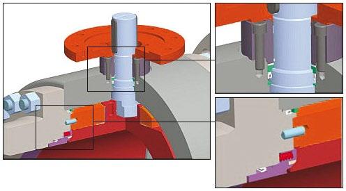
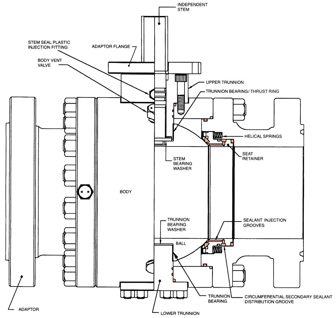
Exploded view upper stem and seat area
6.3 SOFT SEAT INSERT (ONLY FOR VALVE WITH SOFT INSERT)
a- The soft insert shall be free of damages otherwise the seat shall be replaced.
WARNING: due to the specialised manufacturing process, the performance of the seat insert is guaranteed only if manufactured by APV. Do not attempt to press in a new after market seat insert.
b- A non genuine or client made refurbished part will void the warranty.
6.4 SEALS
a- Clean and check the gasket’s status and repair/replace them if damaged.
If a gasket or seal is disturbed while removing or adjusting soft parts, APV recommends installing a new gasket or seal. A proper seal is required to ensure optimum operation.
6.5 SPRING
a- Remove and clean the spring part no. 08 with kerosene or similar solvent.
b- Fill with grease the spring holes on the seats.
c- Check the springs function properly.
d- Assemble the springs on the seats, be careful to avoid any damages to the seat gasket.
6.6 BEARINGS
a- The surfaces of the bearing shall not exhibit any signs of scratches or deep abrasion.
b- If necessary the bearing can be removed acting with the proper tool (screwdriver or chisel) between bearing wall and ball.
c- The new bearing can be forced into the housing.
6.7 BALL
a- Clean the ball, check accurately the surfaces in contact with the seats and bearings.
b- Any damages of the surface must be eliminated by polishing with emery dust. Any deep scratch crossing the whole sealing area shall be cause for rejection.
c- Lubricate accurately all the surfaces with a film of grease.
6.8 STEM SEAL AND STEM
a- Clean the stem surfaces and check in particular the portion in contact with gaskets.
b- The stem shall be free of abrasion, scaling or scratches.
c- Lubricate accurately with the grease.
d- Check seals and replace them if necessary.
Australian Pipeline Valve - Installation, Operation and Maintenance Manual 16 SIDE ENTRY 3P TRUNNION BALL VALVES API6D STANDARD - BVF100 SERIES
6.9 BOLTS, NUTS AND THREADED COMPONENTS
a- All bolts, nuts, and threaded particulars shall be cleaned with kerosene, dried and lubricated with protective oil. The body bolts should have a copper based anti-seize grease applied. To ensure grease does not dry or wash out and does prevent corrosion protective plastic nut caps with grease nipples are available.
b- The threads should be visually inspected to verify the integrity of the components.
7.0 VALVE ASSEMBLY
The sample drawing in Appendix 1 is used as a reference, however, refer to actual as-built drawing as the Bill of Material varies according to size, class and trim.
7.1 VALVE LUBRICATION
For components that need to be lubricated use grease IP Bimol Grease or similar.
7.2 SEAT AND SPRING ASSEMBLY
a- Put the spring part no. 08 into proper housing on the seats part no. 04.
b- Be sure that the flange/body seat area is properly lubricated and position it on a horizontal plane.
c- Insert the o-rings part no. 17 and the fire safe gasket into the grooves of the seat ring part no. 04.
d- Lower the seat ring into the body/flange cavity. Be careful to avoid damaging the gasket.
7.3 FIRST ADAPTOR ASSEMBLY
a- Assemble the adaptor part no. 03 with the body.
b- Screw studs part no. 19 and tighten the nuts part no. 19a (ensure they are pregreased as per 6.9).
c- Refer to Appendix 2 for bolting torques.
7.4 BALL, SUPPORT, BONNET AND STEM ASSEMBLY
a- Assemble the bearings part no. 20, the O-rings part no. 11 and 14 and the gasket with the bonnet part no. 10.
b- Introduce the stem part no. 12 into the bonnet. Be careful to maintain the stem in the same axis of the bonnet.
c- Assemble the ball part no. 02 with the bearings part no. 20a and support part no. 23 and insert the ball in the lateral body cavity.
d- Insert the stem and the bonnet in the ball, through the upper port of the body. Make sure that the stem groove of the key is along pipeline direction, with the ball in the fully open position. Screw and tighten the stop screws part no. 18.
Australian Pipeline Valve - Installation, Operation and Maintenance Manual 17 SIDE ENTRY 3P TRUNNION BALL VALVES API6D STANDARD - BVF100 SERIES
7.5 SECOND ADAPTOR ASSEMBLY
a- Assemble the second adaptor part no. 03 into the body lateral opening.
b- Screw studs part no. 19 and tighten the nuts part no. 19a (ensure they are pregreased as per 6.9).
7.6 GEARBOX MOUNTING TO VALVE
a- Assemble the gear support with the valve.
b- Insert the actuator/gear on the support with the valve.
c- Screw and tighten the studs/nuts actuator.
7.7 PRESSURE TEST
a- Move the ball in the half position.
b- Pressurise the valve body. The body hydrostatic test should be performed at a pressure 1.5 times the maximum rating pressure in accordance with API6D.
c- With the ball in the fully open or closed position the maximum seat hydrostatic test pressure should be be performed at a pressure 1.1 times the maximum pressure rating in accordance with API6D. In addition a low pressure pneumatic test of 700KPA should be performed in accordance with API6D. Seats should be tested bi-directionally.
Refer to API 6D - 2021 for full testing procedures; for full hydrostatic test procedure refer to Sections 10.3, 10.4 & 10.5. For optional pressure gas test refer to Sections I.8, L.19 & L.20. For double block & bleed or double isolation & bleed testing refer to Sections L.9, L.10, L.11, & L.12. For other testing requirements refer to Sections I.4, I.5, I.6, I.7 & L.16.
8.0 OPERATION & MAINTENANCE
The valve is only intended to block or allow flow through the pipeline. The valve should only be used in either fully open or fully closed position. Do not use this valve to regulate flow by partially opening or partially closing the valve. The valve should not stay in a semi-open or semi-closed state for more than two minutes.
8.1 OPERATION INSTRUCTION
a- Hand wheel and gear operated ball valve have to be fully opened and closed to check the valve is correctly operating.
b- In the case of automated valves, the instructions from the actuator’s manufacturer shall be supplied separately. In this case, automated valves shall be operated with the required energy source (electric, pneumatic, hydraulic) to check correct functioning.
c- Do not change any settings such as position stops or speed or torque governing devices.
d- Ball valves are provided with:
Australian Pipeline Valve - Installation, Operation and Maintenance Manual 18 SIDE ENTRY 3P TRUNNION BALL VALVES API6D STANDARD - BVF100 SERIES
• Thrust and radial PTFE/steel bearing;
• Contact surface between ball and seats is anti-wearing and self lubricating. Hence no lubrication and maintenance activity should be required. However, since the valves normally operate with industrial fluids and gases which could have a range of impurities, a preventative maintenance program is required as part of your plant management procedures.
8.2 LUBRICATION
a- Ball valves require no lubrication for normal operation. If required, it’s possible to lubricate the stem and the seats through emergency sealant injection grease-check valve where required when these nipples are provided. This is only in the event of leakage or if the valve is difficult to open. The stem injection nipple can be optionally greased with molybdenum sulphide anti-seize grease to ensure ease of operation especially for automated valves. If no leakage, it’s not required or advisable to lubricate seat sealant injection nipples as the grease may attract debris which could damage the seats longer term. See 8.2b below if seat lubrication is desired or required. Never unscrew complete sealant injection nipples from body as they are under line pressure. Always replace protective caps where fitted to sealant nipples after use.
b- Some end users prefer to lubricate/grease the valve seats at injection points on the seats of the valve located on the valve body. Quantity of grease required can very greatly depending on the valve size, cycle frequency and service condition. As a general guideline use 30 ml (1 ounce) of lubricant per inch size of valve into each seat fitting. Use proper lubricant/grease for you line media application to ensure resistant and compatibility to media and temperature flowing through the line. See 8.4.1 for emergency seat sealant if seats leak.
c- Also see 8.4.1 for emergency seat sealant injection procedures.
8.3 VALVE OPERATING
a- It is advisable, where possible (especially if valve is an actuated ESDV), to move the ball periodically in order to prevent any hard scale or memory lock between ball and seat.
b- Partial operating (at least about 5% of the total stroke) every 6-12 months will ensure a good life of seats and ball. This will ensure the valve functions and will prevent seizure/galvanisation of any mating surfaces. Duration depends on service, criticality, etc. However, it also must be factored in that if there are impurities or particulates in the line each operation could reduce seat life
Australian Pipeline Valve - Installation, Operation and Maintenance Manual 19 SIDE ENTRY 3P TRUNNION BALL VALVES API6D STANDARD - BVF100 SERIES
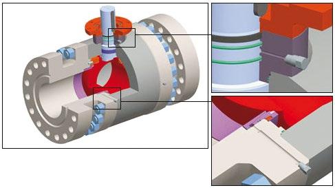
Exploded view stem and body sealant injection
proportionately. However immediately fully re-open or fully re-close the valve as partial opening for more than a few minutes will damage the seat.
c- Before operating with the valve completely open or closed it is advisable to lubricate the internal components as per point 2.4.3 and 2.6.
8.4 MAINTENANCE SCHEDULE
ESTABLISH INTERVALS ACCORDING TO PLANT REQUIREMENTS.
a- Stem packing or seal leakage. In case of leakage from stem seal or packing proceed first to inject sealant through the sealant nipple where provided (see 8.4.1 below). If it does not stop the leak the stem gland seal must be replaced.
b- Body-adaptor leakage. If leakage from body and adaptor join occurs, it is necessary to replace the body gasket.
c- Seat leakage. In case of leakage from seat rings it is possible to inject special silicon grease into emergency seal injection nipples (see 8.4.1 below). Be sure that the grease pump employed for this intervention is able to give a pressure higher than the pipeline pressure.
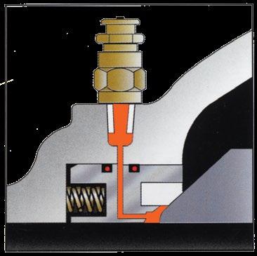
8.4.1 Emergency Sealant Injection Procedure
A sealant is a heavy grease-like substance used to stop small leakages through sealing surfaces. A slightly damaged or scratched sealing surface can still close if some sealant is injected. Sealant injection is intended for temporary emergency situations, where a major valve overhaul to replace the seats is not possible.
Sealant is injected through the grease fittings (25) located in the valve body, near the seat area. Grease fittings are not fitted on all valves as some clients prefer not to have them to prevent the possibility of applying grease unnecessarily which can then attract debris and damage the seat. In smaller size valves there is only a body sealant injection. In this case the valves must be full open during injection, more grease is required as the valve cavity must first fill, then stroke the valve in order to wipe the grease onto the seats. Then repeat the procedure. For normal lubrication see 8.2.
Sealant injection is a temporary measure, remove the valve at first opportunity and repair. Greasing the seats can then attract more debris onto the seats so only grease in an emergency, unless flushing with light grease as shown in Section 2.4.
In most cases, sealant injection in the upstream seat will be enough to stop a small leakage. However, it would probably be necessary to inject sealant each time the valve is operated to keep leakage under control. If standard grease does not work there are many PTFE composite greases with advanced sealing capabilities available.
The procedure for injection of sealant in the seats is as follows:
1. Before injection of sealant, ensure that the ball stops are not out of alignment. A small misalignment
Australian Pipeline Valve - Installation, Operation and Maintenance Manual 20 SIDE ENTRY 3P TRUNNION BALL VALVES API6D STANDARD - BVF100 SERIES
of 2 or 3 degrees may open the bore hole to the line pressure, causing continuous leakage.
2. Use an appropriate high pressure sealant-injection pump, capable of overcoming the pipe pressure and the high pressure build-up caused by the sealant itself, during it’s injection in the sealant passages.
3. Confirm that the ball is in the closed position (unless, as is sometimes the case with valves 80 NB (3”) and under, the valve has a single sealant nipple only on body cavity, then it must be in full open position, see 8.4.1 paragraph 2). Otherwise, the grease will go down the pipeline and the whole procedure will not be effective.
When removing the safety cap of the grease fitting, be careful not to unscrew the complete grease fitting out of the body, because it is under pipe pressure. Use a back-up wrench.
4. Remove the safety cap of the grease fitting.
5. Start injecting a light grade sealant. If you do not succeed, gradually work up to heavier sealants.
6. Recommended quantity is 29 cc (1 oz) of sealant per inch of valve size per seat ring, without considering the quantity required to fill pump and hoses.
7. Inject only enough sealant to stop the leakage. An excess of sealant is wasteful, and contaminates the installation downstream.
APV ball valves optionally feature another sealant injection point in the stem shaft area (25A), to help stop leakage through the O-rings located there. The quantity of sealant required is proportional to the diameter of the shaft (much smaller than the amount required in the seats).
8.5 DOUBLE BLOCK-AND-BLEED
Whilst trunnion ball valves are double block & bleed capable, the valve needs to be ordered and tested as a double block & bleed valve and fitted with a drain valve. A special drain ball valve should be specifically fitted to the lower drain plug.
The pressure trapped in the body cavity can be vented to the atmosphere while pressure, is maintained in the pipeline, both in the fully open and fully closed positions. This characteristic is used to:
1. Ensure that the seats are providing an effective seal.
2. Drain or flush the body cavity of an in-service ball valve.
8.5.1 Venting Procedure
1. Operate the valve to fully open or fully closed position, whichever is more convenient for you.
2. Turn loose the head of the vent fitting (where fitted) (39) located at the top of the body, to release cavity pressure.
Australian Pipeline Valve - Installation, Operation and Maintenance Manual 21 SIDE ENTRY 3P TRUNNION BALL VALVES API6D STANDARD - BVF100 SERIES
Use extreme caution when venting the body cavity of a pressurised valve.
Continue venting until body cavity pressure is atmospheric. It will take some time to depressurise the body cavity. It depends on the size of the fitting, body cavity pressure and field compressibility.
If the body cavity keeps venting fluid at a constant flow rate for a very long time, it is a signal of bad sealing of the valve seats. For liquid service only a lower drain valve will immediately indicate a leak.
8.5.2 Draining Procedure
The purpose of draining the body cavity is to bleed out all the liquid collected in the body cavity. Even in gas service, some condensate, compressor oil and other residues may get trapped in the body cavity after a while. We recommend to drain the body cavity once a year.
Drain the liquids into a suitable bucket to avoid releasing them to the environment. Keep your working area clean. The cavity can be exposed to line or cavity pressure, wear protective eye wear.
To drain the body cavity, proceed as follows:
1. Operate the valve to the fully open or fully closed position, whichever is more convenient for you.
2. Turn loose the head of the drain fitting (24) located at the bottom of the body, to bleed liquids trapped in the body cavity. We recommend a special drain valve specified for this task. It will take some time to bleed the body cavity. It depends on the size of the fitting, pressure in the body cavity and compressibility of the fluid.
If there are hydrates in gas service, the drain fitting may freeze during highpressure draining. Work slowly and ensure that the pressure trapped in the body cavity has been completely released, by opening and closing the drain fitting several times.
Australian Pipeline Valve - Installation, Operation and Maintenance Manual 22 SIDE ENTRY 3P TRUNNION BALL VALVES API6D STANDARD - BVF100 SERIES
9.0
OVER PRESSURE RELIEF
API6D trunnion mounted ball valves with single piston effect seats (SPE) are designed to automatically release cavity overpressure into the pipeline automatically using “self relieving seats”. Since body cavity and pipeline are isolated in the fully open and fully closed position, pressure trapped in the body cavity may be different than pressure in the line. Examples of this situation are during pipeline depressurisation, or heating of body cavity causing a sudden pressure build-up. Overpressure in the body cavity will pop the seats off the ball surface, and excess pressure will be relieved into the pipeline. After the pop-off action, the seats will return to their normal position, in contact with the ball.
The pop-off action is triggered by differential pressure between body cavity and pipeline. The body cavity pressure should not exceed in 1.33 times the valve pressure rating at the specified maximum operating temperature; however, pop-off action usually happens long before, with just a few bars of differential pressure. For standard API6D ball valves, both seats are self relieving. However, on request valves can be ordered with just upstream or just downstream seat as self relieving. Also “double piston effect” (DPE) seats can be specified. DPE seated valves must have an external relief safety valve fitted to the body which vents to atmosphere. Due to environmental requirements this must now be plumbed back into the upstream side of the valve or recycled elsewhere. Refer Section 10.0 for more information.
Both seats are self relieving hence over-pressure can be relieved up or/and downstream. Custom ‘single piston’ seats can be specified on one side, and ‘double piston’ seats on the other side to allow pressure to only automatically relieve just upstream or just downstream.
Australian Pipeline Valve - Installation, Operation and Maintenance Manual 23 SIDE ENTRY 3P TRUNNION BALL VALVES API6D STANDARD - BVF100 SERIES
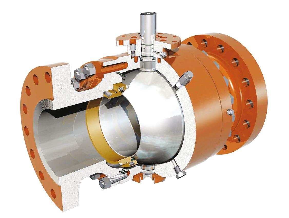
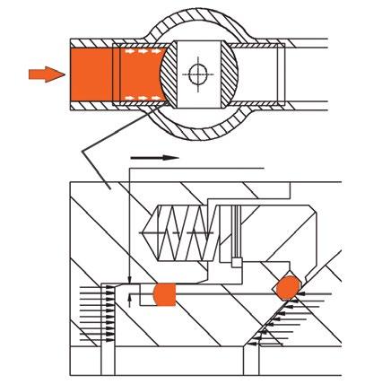
10.0 OVERVIEW DESIGN FEATURES
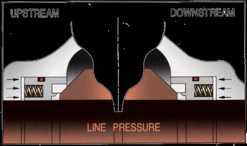
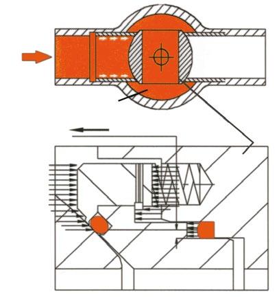
Piston-action seats
As line pressure increases the seat reacts to the force of the pressure to form an effective seal. In the absence of line pressure, coil springs behind the seat provide a tight seal by keeping the seat in contact with the ball surface. Independent floating spring loaded seats are always in contact with the ball to provide an effective tight seal even at low differential pressure. Independent upstream and downstream seats permit draining of fluid from the body cavity, so allowing double block and bleed operation (closed position only). With the optional single sealing feature, there is automatic body cavity release of over pressure to the line through the downstream seat.
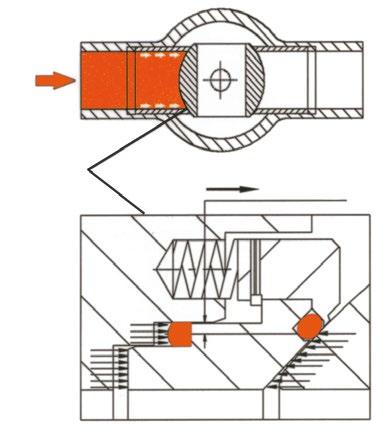
Self relieving seats (standard)
In self relieving condition, excessive internal cavity pressure is automatically relieved both upstream and downstream into the line by excessive pressure forcing the seats away from the ball. Refer Appendix 4 page 28 for more information.
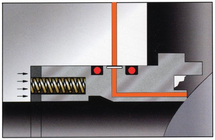
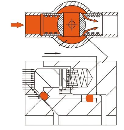
Double piston effect (DPE) seats
With the ‘DPE’ seat option, if a leakage occurs in the upstream seat, the pressure entering the body cavity pushes the downstream seat against the ball and the valve seals. Line pressure forces a seal against the floating seat.
An external body relief valve is installed to protect the body cavity from excess pressure which can be vented to atmosphere or recycled back to the downstream side of the valve or to flare.
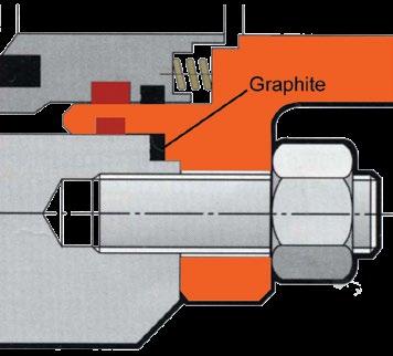
Triple barrier stem seal design
Leakage from the stem area is prevented by double barrier sealing with O-rings as well as graphite fire seals. Leakage through the valve body joint is also protected by double sealing with an O-ring and a flexible graphite gasket. After a fire has deteriorated the -rings, graphite packing and secondary seal ensure prevention of external fluid leakage.
Double block and bleed
Whether in the open or closed position, pressure on each side of the ball is blocked from the body cavity by the seat ring. The cavity can be blown down or drained (only in the closed position) through the body port to indicate line isolation is effective.
Emergency sealing function
In case of fluid leaks from the seat or stem sealing area, a sealant can be supplied through the injection fitting to temporarily prevent leakage.
Australian Pipeline Valve - Installation, Operation and Maintenance Manual 24 SIDE ENTRY 3P TRUNNION BALL VALVES API6D STANDARD - BVF100 SERIES
First Seal Pressure ENERGISE Ball Second Seal Pressure RESPONSE Body Pressure Ball DPE seat design during cavity over pressurisation First Seal Pressure ENERGISE Ball Second Seal Pressure RESPONSE Body Pressure Ball Self relieving seat design during cavity over pressurisation
Piston-action seat are standard and provide bi-directional sealing
APPENDIX 1
The above is indicative only, design depends on size, class and trim, etc. Refer to as-built drawing.
Australian Pipeline Valve - Installation, Operation and Maintenance Manual 25 SIDE ENTRY 3P TRUNNION BALL VALVES API6D STANDARD - BVF100 SERIES
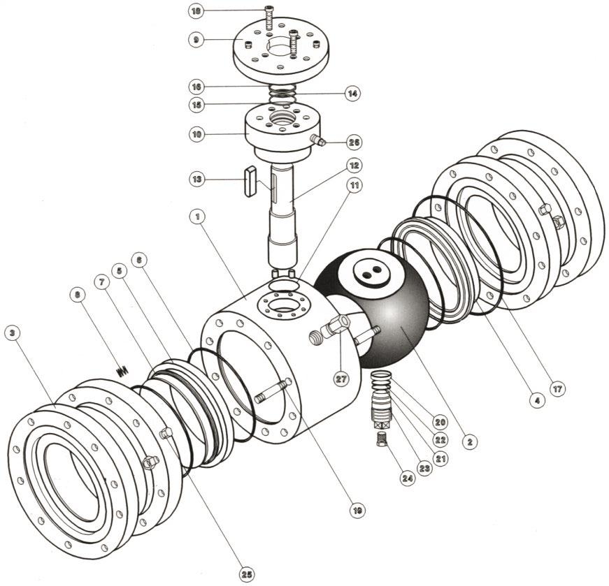
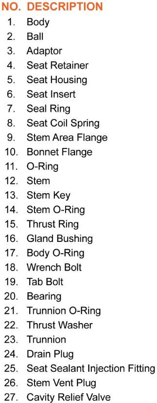
Typical Bill of Materials - BVF100 Series 18 9 16 15 10 13 1 6 5 7 8 3 19 27 24 23 21 20 22 2 4 17 26 12 11 14 25
DIAGRAM 1
Devlon or Nylon or Filled TFE or PEEK or Metal
Viton-B/Viton AED/Viton GLT/Elast-O-Lion 985/Aflas
Inconel X 750
Carbon Steel
Carbon Steel ENP or Carbon Steel
Carbon Steel/Stainless Steel
Viton-B/Viton AED/Viton GLT/Elast-O-Lion 985/Aflas
Phenolic GR.L/316 + PTFE
Viton-B/Viton AED/Viton GLT/Elast-O-Lion 985/Aflas AISI 304/316
Carbon Steel + ENP
Viton-B/Viton AED/Viton GLT/Elast-O-Lion 985/Aflas
Carbon Steel + ENP
316 + PTFE or Phenolic GR.L
ASTM A182 F316
ASTM A182 F316
ASTM A182 F316
Carbon
Carbon
Indicative only. refer to as-built drawing for Bill of Materials.
Australian Pipeline Valve - Installation, Operation and Maintenance Manual 26 SIDE ENTRY 3P TRUNNION BALL VALVES API6D STANDARD - BVF100 SERIES
TABLE 1 Typical Bill of Materials Part No Part Name ASTM A105 ASTM A350 LF2 ASTM A182 F316 1 Body ASTM A105 ASTM A350 LF2 ASTM A182 F316 2 Ball ASTM A105 ENP ASTM A350 LF2 ENP ASTM A182 F316/F51 3 Adaptor ASTM A105 ASTM A350 LF2 ASTM A182 F316 4 & 5 Seat Retainer Ring/ Housing ASTM A105 ENP ASTM A350 LF2 ENP ASTM A182 F316/F51 6 Seat Insert 7 O-Ring, Seat Ring 8 Spring, Seat Ring 9 Adaptor Plate (Neck/Flange) 10 Gland AISI 304/316 11 O-Ring, Gland 12 Stem 17-4 PH/316/S31803 13 Stem Key 14 O-Ring, Stem 15 Thrust Washer, Stem 16 Bushing 17 O-Ring, Body 18 Cap Screw, Adaptor Plate Stainless Steel 19 Stud Body ASTM A193 B7 + ZP ASTM A320 L7 + ZP ASTM A193 B8/B8M 19A Nut, Body ASTM A192 2H + ZP ASTM A194 Gr.7 + ZP ASTM A192 8/8M 20 Bearing 21 O-Ring, Trunnion 22 Thrust Washer, Ball 23 Trunnion ASTM A105 ENP ASTM A350 LF2 ASTM A182 F316 24 Drain Plug Carbon Steel ASTM A350 LF2 ASTM A182 F316 25 Grease Fitting, Seat 25A Grease Fitting, Stem 26 Stem Vent Plug ASTM A105 + ZP ASTM A350 LF2 + ZP AISI 304/316 27 Vent Valve c/w Check* ASTM A182 F316 28 Lifting Lug 29 Support 30 Worm Gear Operator 31 Adaptor Plate, Worm Gear 32 Handle 33 Body Gasket (not shown) 34 Gland & Trunnion Seal (not shown) 35 Stem Packing (not shown) * Manual vent only (exposed to full line pressure - take care!) Graphite Graphite Carbon Steel
Steel Assembly
APPENDIX 1 CONT’D
Carbon
Steel
Graphite/Spiral Wound 316
+ PTFE coated/Du Dry Bearing Viton-B/Viton AED/Viton GLT/Elast-O-Lion
AISI 1018-1045 ENP/17-4PH/F6A
Steel
316
985/Aflas
Sample Drawing 600 Class Gear Operated


Example only, refer to as-built drawing
Australian Pipeline Valve - Installation, Operation and Maintenance Manual 27 SIDE ENTRY 3P TRUNNION BALL VALVES API6D STANDARD - BVF100 SERIES
CONT’D
APPENDIX 1
API607 5th & 6th Ed. ISO 10497 Firesafe Certi ed ISO 15848-1 Fugitive Emission Certi ed www.australianpipelinevalve.com.au APV DWG FRM 142 1 3 2 4 5 6 17 18 21 24 22 36 35 32 30 34 43 13 20 14 16 19 15 28 27 26 25 23 29 12 11 SECTIONAL DWG SECTIONAL DWG SECTIONAL DWG 40 41 42 45 44 37 38 39 41 41 Dimensions in millimeters Trunnion Firesafe Ball Valve, 3 PC, Model BVF100-FTIZ2523EBEEB API6A 7-1/16” 5000 PSI, RTJ PSL2 PR1, Gear Operated, FB, 4140 ORDER N o / DWG N o REV. APPROVED CHECKED DRAWN 142 00 DIMENSIONS (MM) & WEIGHT (KG) A(RTJ) B B1 C D G E 711 179.4 179.4 395 254 309 243 Australian Pipeline Valve B.T. S.Q. C.C. Inch 7-1/16” I 460 Weight 620 BILL OF MATERIALS NO. PART NAME QTY MATERIAL NOTES RATING DESIGN & MFG. PRESS-TEMP RATING FACE TO FACE DIM. END CONNECTION END DIMENSION TEST & INSPECTION MARKING OTHER REQ. PORT SIZE TRIM NOTES OTHER API6A 5000
RTJ
7
PR4 ANTI STATIC BS5351/ ISO 17292-2010 TEST PRESSURE SHELL HYDRO SEAT HYDRO SEAT AIR BACKSEAT TEMPERATURE MEDIUM Water, Oil, Gas ºC -29 TO 175 ºF -80 TO 347 Mpa Psi 0.6 87 Mpa Psi Mpa Psi Mpa Psi 51.7 7500 34.75 5000 SPECIAL OPTIONAL LP AIR SEAT TEST ALSO PERFORMED H
1 CLOSURE 2 AISI 41402 BODY STUD SET ASTM A193 B7M3 BODY NUT SET ASTM A194 2HM4 PIN 4 STAINLESS STEEL5 TRUNNION PLATE 2 4140+ENP6 BODY 1 AISI 414011 BODY O-RING 2 VITON AED12 BODY FIRESAFE GASKET 2 GRAPHITE (1) 13 SEAT SPRING INCONEL X-75014 SEAT O-RING 4 VITON AED15 SEAT 2 ASTM A182 F5116 SEAT INSERT 2 DEVLON17 WASHER STAINLESS STEEL+PTFE18 BALL BEARING STAINLESS STEEL+PTFE19 FIRESAFE GASKET 2 GRAPHITE (1) 20 SEAT PLATE 2 ASTM A182 F5121 BALL ASTM A182 F5122 BALL BEARING 1 STAINLESS STEEL+PTFE23 STEM WASHER STAINLESS STEEL+PTFE24 ANTI-STATIC DEVICE INCONEL X-75025 BONNET O-RING 1 VITON AED26 BONNET FIRESAFE GASKET GRAPHITE27 STEM O-RING 2 VITON AED28 STEM FIRESAFE GASKET 1 GRAPHITE (2) 29 BONNET AISI 4140+ENP (1) 30 STEM KEY CARBON STEEL ZINC PLATED 32 STEM ASTM A182 F51 (2) 34 BONNET FLANGE 414035 BONNET CAP SCREW SET ASTM A193 B736 BONNET FLANGE CAP SCREW SET ASTM A193 B737 GEARBOX ASTM A105N (3) LOCKABLE 38 GEARBOX STUD SET ASTM A193 B739 GEARBOX NUT SET ASTM A194 2H40 BLEED VALVE STAINLESS STEEL41 SEAT INJECTION FITTING 2 STAINLESS STEEL42 DRAIN PLUG 1 STAINLESS STEEL43 STEM INJECTION FITTING STAINLESS STEEL44 LIFTING LUG 2 CARBON STEEL+ZP45 SUPPORT LEG 2 CARBON STEEL(1) BONNET SEAL AREA & BODY SEAL AREA SMOOTHNESS Ra ≤ 3.2 µ m (2) STEM SMOOTHNESS Ra ≤ 0.80 m (3) LOW RATIO GEARBOX (:) ? TURNS TO OPEN PROTECTION LEVEL IP67
PSI API6A, API6D API6A ASME B16.10
API6A API6A MSS SP-25 NACE MR-01-75 API6A TEMP P ~ X
1/16 ” THROUGH PORT F51 TRIM API6A EE FIRESAFE: ISO 10497, API607 5TH/ 6TH PSL2
235
APPENDIX
Body Bolting Torques
2
Stud Size
Bolting Material
1
1
(2035) 1907 (2585)
(3195)
(3898)
2
2
Note:
(8136) 7500 (10170)
(1) Torques shown are for A193 B7/B7M/B8/B8M and A320 L7/L7M/B8/B8M.
(2) Torque tolerance ±10%.
(3) For temperatures above 750°F (400°C) use 75% of the torque values.
(4) Above torque values are with the bolts lubricated.
(5) Values above are based on 30,000 psi (206.85 Mpa) bolting stress and lubricated with heavy graphite and oil mixture or a copper based anti-seize grease.
(6) Do not exceed by more than 25% of values stated when emergency torquing is required.
(7) All bolts shall be torqued in the pattern as shown in Diagram 2 to ensure uniform gasket loading.
(8) Optimum torque can vary depending on type of body gasket but do not increase torque more than 10% above those shown.
(9) Consult us for other bolt material.
(10) Most B8M and B8 bolts are class 1 so do not assume class 2 unless you are sure.
Indicative torques are shown only, different body gasket systems, different seating styles, different sizes & classes etc., will have different torque requirements. Furthermore, other stud grades can have much lower torques depending if class 1 or class 2 and or above variables. Bolt tensions shown must be decreased by 25% when other or no lubrication is used. Non lubricated bolts can have an efficiency of 50% less than the torque values stated.
Australian Pipeline Valve - Installation, Operation and Maintenance Manual 28 SIDE ENTRY 3P TRUNNION BALL VALVES API6D STANDARD - BVF100 SERIES
TABLE 2 Indicative body bolting torque ft·lb (N·m) 3/8 - 16 UNC 15 (20) 20 (27) 15 (20) 20 (27) 7/16 - 14 UNC 25 (34) 30 (41) 22 (30) 25 (34) 1/2 - 13 UNC 40 (54) 50 (68) 35 (47) 45 (61) 9/16 - 12 UNC 55 (75) 70 (95) 55 (75) 65 (88) 5/8 - 11 UNC 75 (102) 100 (136) 70 (95) 85 (115) 3/4 - 10 UNC 135 (183) 170 (231) 125 (170)150 (203) 7/8 - 9 UNC 200 (271) 270 (366) 170 (230)200 (271) 1 - 8 UNC 350 (475) 400 (542) 219 (298)350 (475) 1 1/8 - 8 UN 500 (678) 520 (705) 256 (398)450 (610) 1 1/4 - 8 UN 675 (915) 850 (915) 321 (498)650 (881) 1 3/8 - 8 UN 900 (1220) 1200 (1627) 384 (598)900 (1220) 1 1/2 - 8 UN 1200 (1627) 1500 (2034) 1200 (1627)
5/8 - 8 UN 1600 (2170) 2000 (2712)
3/4 - 8 UN 2000 (2712) 2500 (3390) 1 7/8 - 8 UN 2500 (3390) 3100 (4204) 2 - 8 UN 3000 (4068) 3800 (5153)
1/8 - 8 UN 3600 (4882) 4500
2
(6102)
1/4 - 8 UN 4400 (5966) 5400
(7322)
1/2 - 8 UN 6000
2357
2876
1501
B7M/L7M B7/B16/L7 B8/B8M CL.1 B8/B8M CL.2
APPENDIX 2 CONT’D
DIAGRAM 2
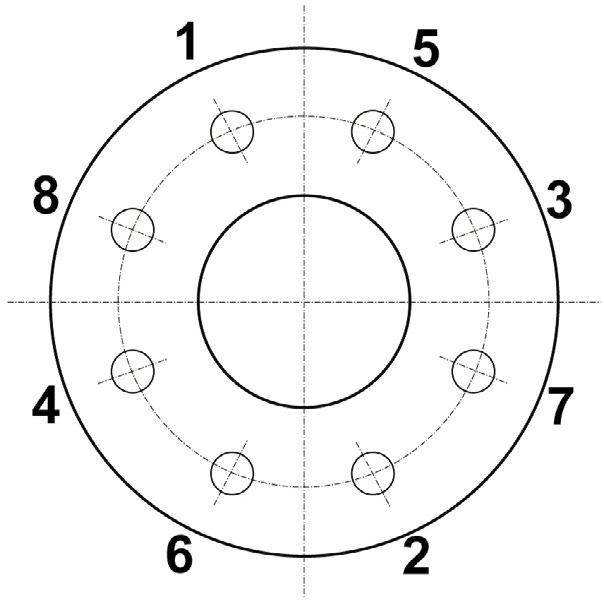
torque sequence:
Stud Lubrication
• Re-tightening of body (with system de-pressurisation) bolting is permissible, if body leakage occurs.
• Required Torque values are given in Table 2.
• Use a Copper-Based Anti-Seize Grease for stud lubrication.
Australian Pipeline Valve - Installation, Operation and Maintenance Manual 29 SIDE ENTRY 3P TRUNNION BALL VALVES API6D STANDARD - BVF100 SERIES
Bolting
1 - 2 - 3 - 4 - 5 - 6 - 7 - 8
APPENDIX 3
TABLE 3 APV VALVE IDENTIFICATION LABEL
1
2
3
4
5
*
*

Australian Pipeline Valve - Installation, Operation and Maintenance Manual 30 SIDE ENTRY 3P TRUNNION BALL VALVES API6D STANDARD - BVF100 SERIES
No. Figure Number Code Description
Figure Number Identifies the detailed valve confirguation
(valve type, bore size, pressure class, materials, etc.)
Serial Number Identifies certified manufacturers serial number & stock code
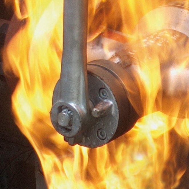
Firesafe Identifies firesafe standard
Standard Identifies manufacturing design & standard
Body Material Identifies body material composition (A105, WCB, F51, CF8M, etc.)
Pressure Classes Identifies pressure classification per API requirements
Size Identifies bore size
Seat Material Identifies seat material composition (PEEK, Teflon, Nylon, etc.)
Ball Material Identifies ball/disc material composition (A105, 316SS, ENP, etc.)
Stem Material Identifies stem material composition (A105, 410SS, 17-4pH, etc.)
MAX WP @ Identifies maximum pressure at minimum temperature
MAX WP @ Identifies maximum pressure at maximum temperature
6
7
8
9
10
11
12
NACE MR0175 Identifies corrosion resistance
NACE is indicated by a separate NACE
APV TM/FL 6D Ball Label API6D API607 FIRESAFE ASME B16.34 BODY CLASS SIZE BALL STEM MAX WP@ MAX WP@ SEAT 3 4 7 5 2 4 6 8 11 9 1 12 10
tag.
SIDE ENTRY 3P TRUNNION BALL VALVES API6D STANDARD - BVF100
APPENDIX 4
DESIGN FEATURES
Manufacturing Specifications
Specification
Standards
General design standard API6D
Pressure-temperature rating
Face to face dimensions
ASME B16.34
ASME B16.10
Flange type and dimensions ASTM B16.5
Butt-weld ends
Inspection and test
APV Trunnion Mounted Ball Valve Construction Features Function Up-stream Sealing Two-way Valve
The up-stream seal of the valve is effected by the advanced spring pre-tightening seats which automatically adjust. The two-way valve has two seats that can be sealed in both directions, so there’s no limitations of flow direction during installation. As line pressure increases the seat reacts to the force of the pressure to form an effective seal. In the absence of line pressure, coil springs around the seat unit provide a tight seal by keeping the seat in contact with the ball.
Double Block & Bleed Valve
Being “up-stream side sealing”, the valve can bleed out the trapped fluid in the body cavity when the valve’s in fully open or fully closed position. The fluid is intercepted by seats on the up-stream and down-stream side. Bleeding the dirty fluid periodically can reduce damage of the sealing surface and prolong the service life of the valve.
ASME B16.25
API6D/API598/ISO14313
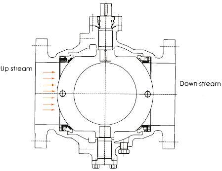
DIAGRAM 3
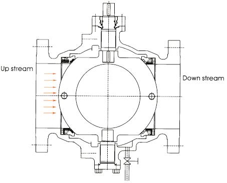
DIAGRAM 4
Australian Pipeline Valve - Installation, Operation and Maintenance Manual 31
SERIES
Down stream Up stream
Down stream Up stream
APPENDIX 4 CONT’D
Automatic Relief of the Cavity
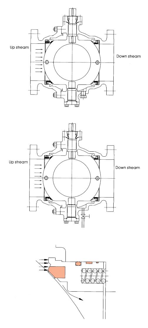
DIAGRAM 5
Independent floating spring loaded seats are always in contact with the ball to provide an effective tight seal even at low differential pressures. Independent upstream and downstream seat permit draining of fluid from the body cavity, allowing double block and bleed operation. With the standard ‘single sealing’ feature, when the valve is closed there is an automatic body cavity release of over pressure to the line through the downstream (or upstream) seat. The pre-tightened seat springs are preset to automatically relieve excess cavity pressure caused by thermal expansion back downstream (or upstream). Once pressure exceeds the API6D (6.8) maximum (1.33 times the valve maximum pressure rating at 38°C at the time of publishing this IOM). Refer section 10.0 for more information.
‘Double sealing’ feature (available on request), maintains the sealing capacity of the valve even in the case of failure of the upstream seat. Body cavity over pressure in this case can be released through a relief valve to atmosphere or flare, or can be recycled back upstream. A combination of double sealing features on the downstream side and single sealing on the upstream seat is available on request. This configuration maintains the sealing capacity of the valve in case of failure of the upstream seat and release of the body cavity over pressure through the upstream seat.
Full Bore or Reduced Bore
Full bore and reduced bore are available in all sizes. Full bore is full through conduit bore size to API6D to facilitate pigging.
Sealant Injection System
When the seat and/or stem sealing system is damaged, the grease injection valve can inject sealant into the valve for temporary sealing. Under normal circumstances Australian Pipeline Valve valves require no lubrication.
Stem Sealing System
Two O-rings are utilised in the stem area for reliable performance, as well as graphite fireseal.
Flexible Operation
The seat and stem bearing has a Teflon coating which is low friction and self-lubricates to reduce the valve operation torque.
Operators
The valve may be operated by hand, pneumatic operator, motor, hydropneumatic operator and hydraulic operator, etc.
NACE
The full range of APV valves can meet NACE standard MR-01-75, latest edition if necessary.
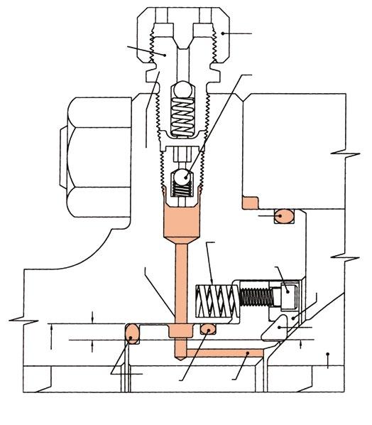
DIAGRAM 6
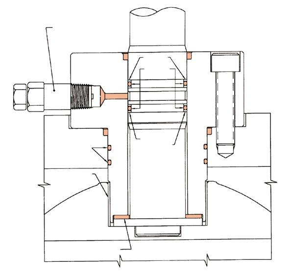
DIAGRAM 7
Australian Pipeline Valve - Installation, Operation and Maintenance Manual 32 SIDE ENTRY 3P TRUNNION BALL VALVES API6D STANDARD - BVF100 SERIES
SEALANT INJECTION FITTINGS END HEIGHT OF THE DIFFERENTIAL AREA SEAT O-RINGS BALL SEALANT GROOVE D2 SEAT INSERT SAFETY CAP VALVE BODY-END O-RING SEAT SPRING HOLDING SCREWS SEAT RETAINER RING SECONDARY SEAL CHANNEL
STEM RINGS BACK-UP RINGS O-RINGS BODY STEM PLASTIC PACKING INJECTION FITTING UPPER BODY SEALS UPPER TRUNNION BEARING STEM BEARING WASHER
WARRANTY
1. LIMITED WARRANTY: Subject to the limitations expressed herein, Seller warrants that products manufactured by Seller shall be free from defects in design, material and workmanship under normal use for a period of one (1) year from installation but in no case shall the warranty period extend longer than eighteen months from the date of sale. This warranty is void for any damage caused by misuse, abuse, neglect, acts of God, or improper installation. For the purpose of this section, “Normal Use” means in strict accordance with the installation, operation and maintenance manual. The warranty for all other products is provided by the original equipment manufacturer.
2. REMEDIES: Seller shall repair or replace, at its option, any non-conforming or otherwise defective product, upon receipt of notice from Buyer during the Manufacturer’s warranty period at no additional charge. SELLER HEREBY DISCLAIMS ALL OTHER EXPRESSED OR IMPLIED WARRANTIES, INCLUDING, WITHOUT LIMITATION, ALL IMPLIED WARRANTIES OF MERCHANTABILITY AND FITNESS OR FITNESS FOR A PARTICULAR PURPOSE.
3. LIMITATION OF LIABILITY: UNDER NO CIRCUMSTANCES SHALL EITHER PARTY BE LIABLE TO THE OTHER FOR INCIDENTAL, PUNITIVE, SPECIAL OR CONSEQUENTIAL DAMAGES OF ANY KIND. BUYER HEREBY ACKNOWLEDGES AND AGREES THAT UNDER NO CIRCUMSTANCES, AND IN NO EVENT, SHALL SELLER’S LIABILITY, IF ANY, EXCEED THE NET SALES PRICE OF THE DEFECTIVE PRODUCT(S) PURCHASED DURING THE PREVIOUS CONTRACT YEAR.
4. LABOR ALLOWANCE: Seller makes NO ADDITIONAL ALLOWANCE FOR THE LABOR OR EXPENSE OF REPAIRING OR REPLACING DEFECTIVE PRODUCTS OR WORKMANSHIP OR DAMAGE RESULTING FROM THE SAME.
5. RECOMMENDATIONS BY SELLER: Seller may assist Buyer in selection decisions by providing information regarding products that it manufacturers and those manufactured by others. However, Buyer acknowledges that Buyer ultimately chooses the product’s suitability for its particular use, as normally signified by the signature of Buyer’s technical representative. Any recommendations made by Seller concerning the use, design, application or operation of the products shall not be construed as representations or warranties, expressed or implied. Failure by Seller to make recommendations or give advice to Buyer shall not impose any liability upon Seller.
6. EXCUSED PERFORMANCE: Seller will make a good faith effort to complete delivery of the products as indicated by Seller in writing, but Seller assumes no responsibility or liability and will accept no back-charge for loss or damage due to delay or inability to deliver, caused by acts of God, war, labor difficulties, accidents, inability to obtain materials, delays of carriers, contractors or suppliers or any other causes of any kind whatever beyond the control of Seller. Under no circumstances shall Seller be liable for any special, consequential, incidental, or indirect damages, losses, or expense (whether or not based on negligence) arising directly or indirectly from delays or failure to give notice of delay.
Australian Pipeline Valve - Installation, Operation and Maintenance Manual 33 SIDE ENTRY 3P TRUNNION BALL VALVES API6D STANDARD - BVF100 SERIES

www.australianpipelinevalve.com.au AUSTRALIAN PIPELINE VALVE® HEAD OFFICE 70-78 Stanbel Road Salisbury Plain South Australia 5109 Telephone +61 (0)8 8285 0033 email: admin@australianpipelinevalve.com.au If you have any requirements in the field of valves, please contact us for a prompt response. Continuous development of Australian Pipeline Valve products may necessitate changes in the design or manufacture process. Australian Pipeline Valve reserves the right to effect any such changes without prior notice. © Australian Pipeline Valve 1990 - 2024 Edition LOCAL DISTRIBUTOR/AGENT IOM APV Ball TM 3P BVF100
