SAFETY INFORMATION
The following general safety notices supplement the specific warnings and caution as appearing in this manual. They are recommended precautions that must be understood and applied during operation and maintenance of the equipment covered in this I.O.M.
Never attempt to disassemble a valve while there is pressure in the line. Ensure both upstream and downstream pressures are removed. Disassemble with caution in the event all pressures are not relieved. Even when replacing packing seals, caution is necessary to avoid possible injury.
To prevent valve bending, damage, inefficient operation, or early maintenance problems, support piping on each side of the valve.
• A valve is a pressurised mechanism containing energised fluids under pressure and consequently wshould be handled with appropriate care.
• Valve surface temperature may be dangerously too hot or too cold for skin contact.
• Upon disassembly, attention should be paid to the possibility of releasing dangerous and or ignitable accumulated fluids.
• Ensure adequate ventilation is available for service.
This manual provides instructions for storing, general servicing, installation and removal of needle valves.
APV - Flowturn and it’s resellers refuse any liability for damage to people, property or plant as well as loss of production and loss of income under any circumstances but especially if caused by: Incorrect installation or utilisation of the valve or if the valve installed is not fit for intended purpose. It is the sole responsibility of the client to ensure the valve type and materials are correctly specified.
Australian Pipeline Valve - Installation, Operation and Maintenance Manual 3 SOFT SEATED PLUG TYPE NEEDLE VALVE - S-H1, S-M5A, S-M5F, S-M9S
DURING OPERATION BEAR IN MIND THE FOLLOWING WARNINGS:
a- Graphoil packing/seals where used are very brittle, any twisting or bending shall be avoided.
b- The internal parts of valves (plug, tip, stem, seat) shall be handled with care avoiding scratches or surface damage.
c- All tools and equipment for handling and supporting the internal parts shall be coated with soft materials.
d- Seats & seals can include Viton, Devlon, Nylon & Teflon hence high temperatures, and some chemicals, will damage sealing components.
e- Never part open or part close straight through style valves. Valve must be fully open or fully closed else seats will be damaged.
For all operations make references to position number on part list of the applicable drawing listed.
INTRODUCTION
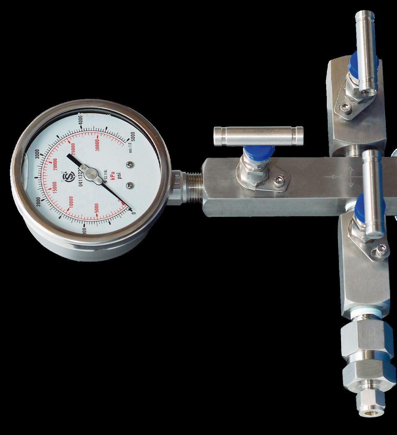
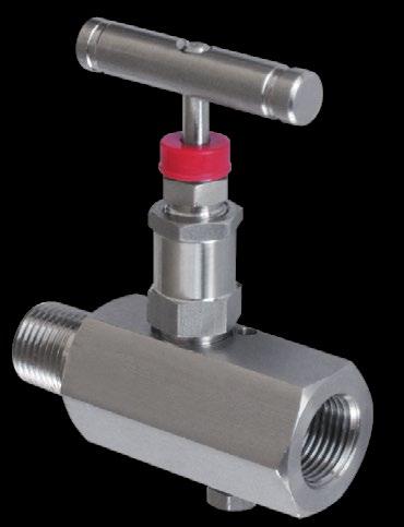
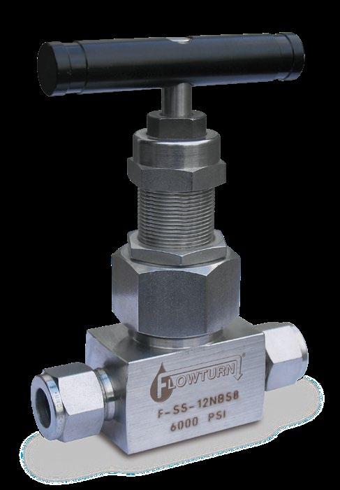
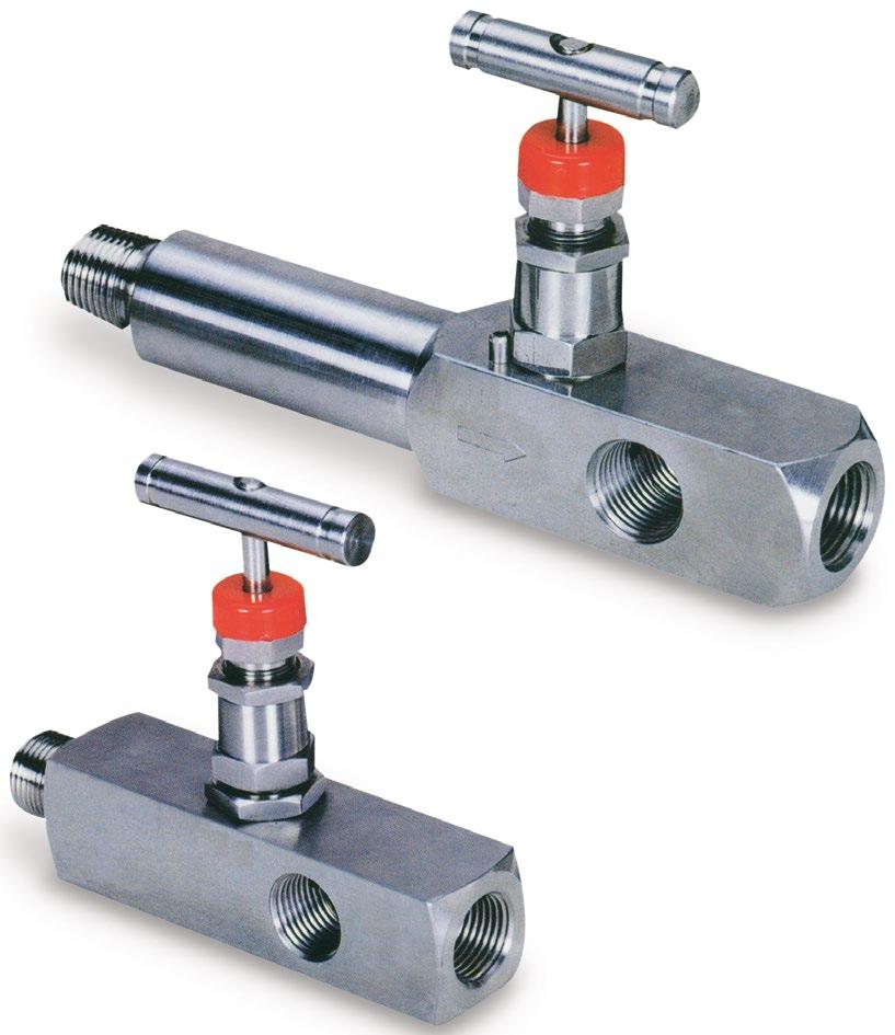
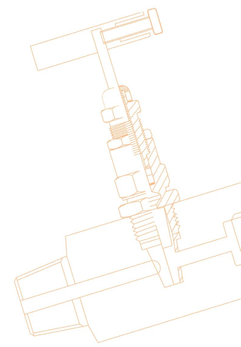
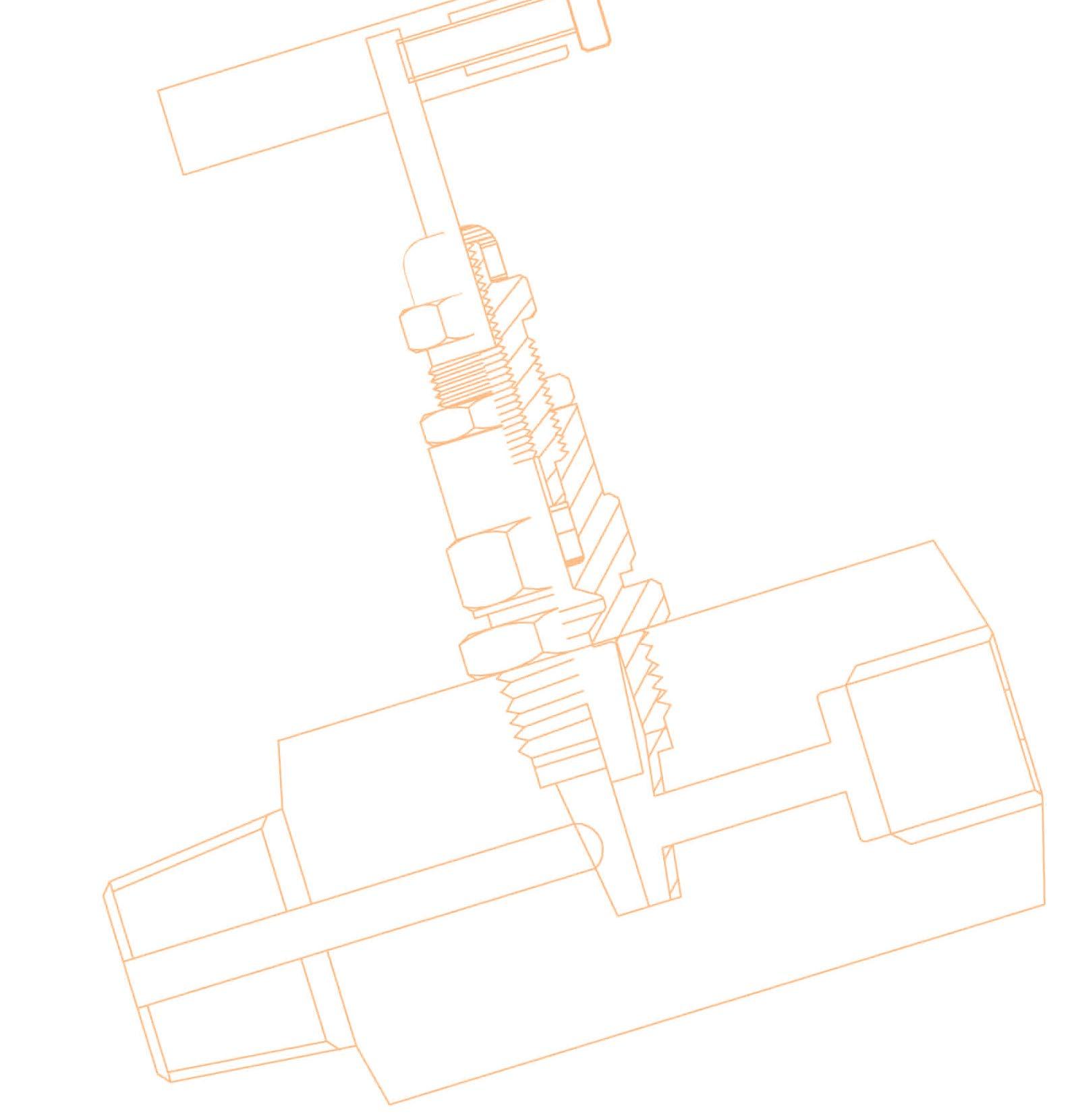
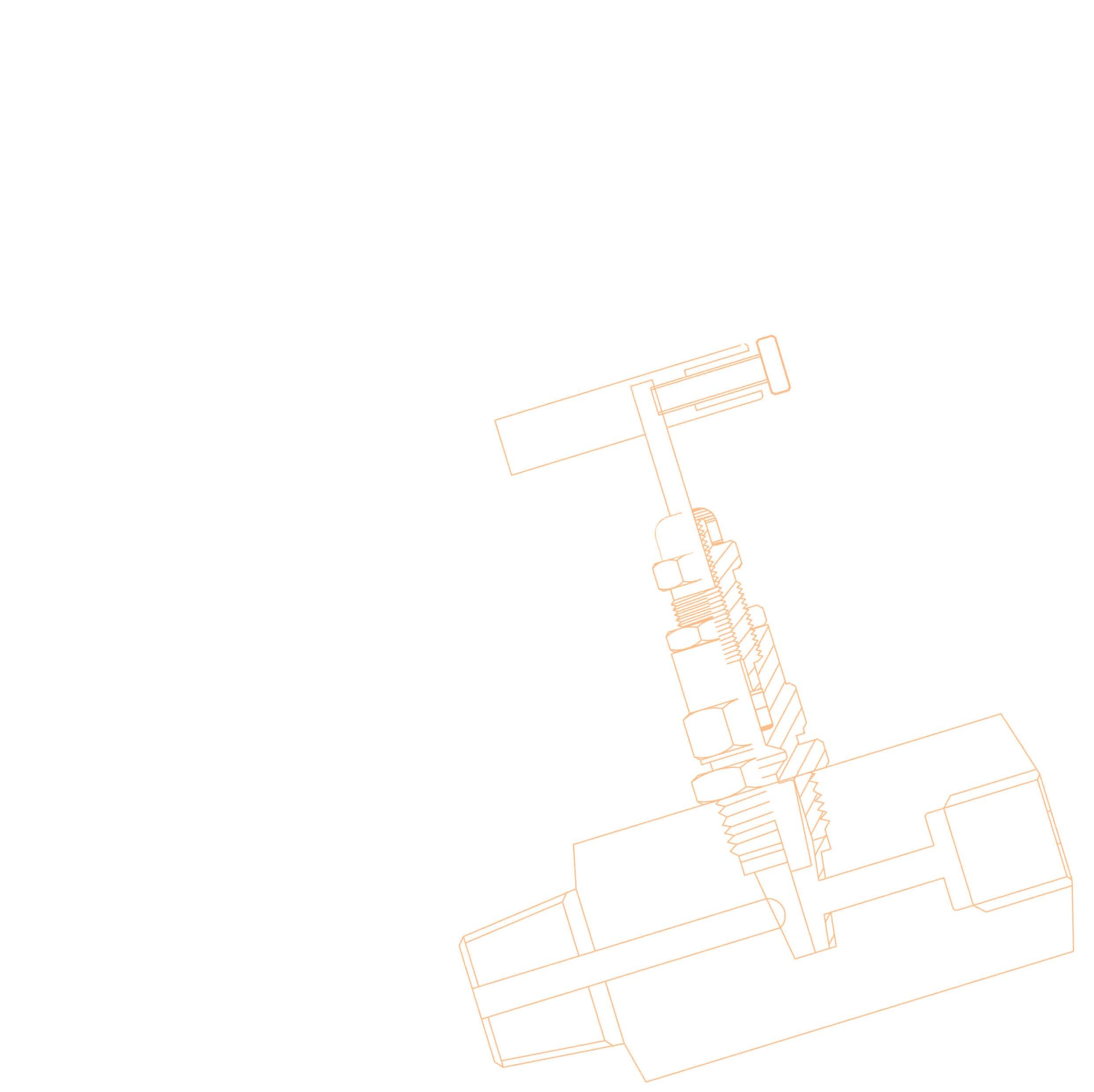
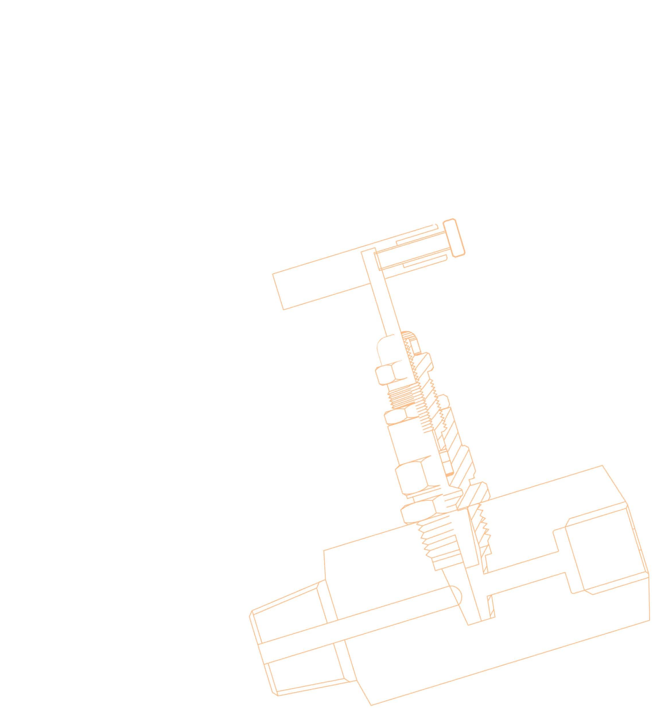
Flowturn S-H1, S-M5A, S-M5F and S-M9S Needle valves are larger port (3/8” & 5/8”) straight through (roddable) plug type soft seat needle valves. These valves have a rotating stainless steel conical v-tip plug that seals on a replaceable resilient large area seat sleeve and features below the thread packing. Teflon or Graphite packing is provided. These valves are available in a variety of end connections. For maximum pressure-temperature ratings on soft seat materials refer to catalogue or consult us. Where Teflon packing is used the maximum temperature rating is 200°C. Delrin, Devlon and Nylon seats should not be used above 150°C, but consult pressure/temperature charts. Only APV approved valve repairer should undertake complete reconditioning or major repairs.
1.0 INSTALLATION
1. S-H1, S-M9S, S-M5A valves are bi-directional and can be used in vertical or horizontal service and at any degree of incline.
2. Prior to valve installation, check the piping to which the valve is to be connected for cleanliness and remove any foreign materials.
3. Threaded joints require an intimate fit between the male and female pipe threads. The use of a thread sealant is recommended. Ensure the fitting connections are made up tight.
4. Keep the valve partially open during welding to avoid transmitting extra heat from the plug tip to the soft seat. Excessive heat will damage the resilient seat which is PTFE or Devlon. To further minimise the risk of heat damage graphite stem packing can be specified. All welding should be in accordance with any code or applicable regulations relevant to the piping system construction and with complete and approved welding procedures. Heat input should be kept to a minimum by controlling the amperage and voltage to the lowest practical levels. A minimum travel speed of three (3) I.P.M.
Australian Pipeline Valve - Installation, Operation and Maintenance Manual 4 SOFT SEATED PLUG TYPE NEEDLE VALVE - S-H1, S-M5A, S-M5F, S-M9S
should be maintained and the interpass temperature should not exceed 93°C (200°F). GTAW weld type should be employed with argon gas and a maximum diameter weld rod of 1/8”. Only a certified welder with experience in welding this type of valve should be used.
2.0 OPERATION
The user should ensure suitably qualified specialist engineers have matched the valve type to the valve service application and ensure valves are properly installed. Valves have moving and wearing parts and depend on long-term preservation of highly finished surfaces on these parts for satisfactory valve performance.
1. The use of excessive force, additional leverage or over cheating to operate the valve handle is not recommended. This practise can cause valve damage.
2. All needle valves have rising stems with right hand thread. Rotate the handle counter-clockwise to open and clockwise to close.
3.0 MAINTENANCE
Valves which remain in one position for long periods of time are even more likely to require maintenance attention due to the loss of effective lubricants in threads, aging of packing, surface corrosion or moving parts or accumulation of harmful solids. Depending on the surface conditions, environment type, temperature, frequency of use, pressure, etc. In some applications it may become necessary to schedule periodic partial or full cycle exercising and maintenance of these valves.
1. Stem packing leakage usually results from seal wear, and can usually be corrected by tightening the bonnet bushing. Over tightening can cause high stem friction, accelerated wear and shortened stem seal life.
2. If stem packing replacement is needed, safe practice requires depressurising the valve before removal of the bonnet bushing. Use of backseat (where present) to permit repacking under pressure should be considered unsafe.
Always wear appropriate safety wear and ensure all fluids and media are drained prior to commencing maintenance.

Australian Pipeline Valve - Installation, Operation and Maintenance Manual 5 SOFT SEATED PLUG TYPE NEEDLE VALVE - S-H1, S-M5A, S-M5F, S-M9S
3.1 STEM SEAL REPLACEMENT
Teflon and Graphite seals/packings do not often need replacement if leakage occurs usually the leak can be stopped by tightening the bonnet bushing.
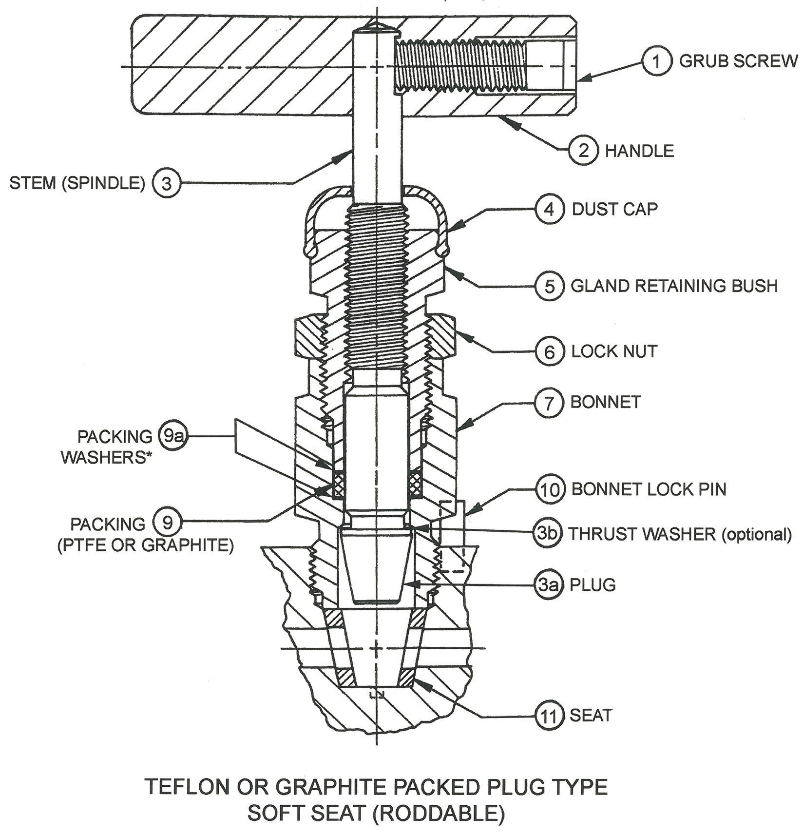
1. Refer to Table A in the Appendix for identification of parts. The design may vary according to size, rating special bonnet options, and trim. Refer to the as-built drawing supplied with the data package.
2. Remove bonnet lock pin (item #10) from valve body, using pliers or wire cutters.
3. Unscrew bonnet counter-clockwise to remove bonnet assembly from the valve.
4. Place bonnet in soft-jawed vice to facilitate disassembly.
5. Remove T-bar handle (part #2) by loosening grub screw (part #1).
6. Remove plastic dust cover (part #4) from gland retainer bush (part #5).
7. Loosen lock nut (part #6) and unscrew bush off stem.
8. Remove valve stem (part #3) from bonnet (part #7) by screwing downward.
9. Remove Teflon or Graphite stem packing (part #9) and the two washers (part #9a).
10. Slide out the complete plug & spindle (part #12) and thrust washer (part #12a), (only on some models).
11. Clean all parts with suitable cleaner such as acetone.
12. Inspect all parts for damage; especially the threads and stem tip area. Replace both the stem and bonnet bush if threads do not engage smoothly.
13. Lubricate the stem (part #3) threads and bush (part #5) with lubricant resistant to the service in which the valve is being used.
14. Re-insert the stem and tip (part #3/3a) into the end of the bonnet that is threaded externally.
15. Push the stem upward from the bottom of the bonnet.
16. Place the stem packing (part #9) and packing washers (part #9a) over the stem and push it down into the bonnet.
17. Place the retainer bush (part #5) with lock nut (part #6) over the stem and hand screw the threads. Screw the bushing down into the bonnet until it reaches the stem seal.
18. Place the dust cover (part #4) over the valve stem (part #3).
19. Place the handle (part #2) and tighten the grub screw where applicable (part #1) to 1.38-1.66 kg-m (10-12 ft·lbs). Take care not to bend the stem.
Do not attempt to replace stem packing in-line, especially if under line pressure.
Australian Pipeline Valve - Installation, Operation and Maintenance Manual 6 SOFT SEATED PLUG TYPE NEEDLE VALVE - S-H1, S-M5A, S-M5F, S-M9S
3.2 REASSEMBLY OF THE VALVE
1. Lubricate the bonnet threads with appropriate lubricant.
2. Insert the bonnet into the seat cavity hand screw the bonnet into the valve body.
3. Then tighten the bonnet to the torque value shown below:
3/8” orifice valves: - 6.9-8.3 kg-m (50-60 ft·lbs)
5/8” orifice valves: - 17.94-19.32 kg-m (130-140 ft·lbs)
4. Tighten bonnet bush with a wrench, take care not to over tighten. Then check the tightness by turning the handle. If it feels too loose, tighten the bush more. It is feels tight, the stem packing should be replaced and the bush again retightened.
5. The bush tightness requires judgement and experience. It if is too loose the bonnet will leak. If it is too tight, the handle will be hard to turn and the stem seal may be damaged.
6. Then tighten the lock nut (part #6) to lock the bush in place.
7. Replace bonnet lock pin.
3.3 SEAT REPLACEMENT
It seat replacement is required, depressurise the valve before removal of the bonnet.
1. Refer to Appendix Table A for parts identification.
2. Remove bonnet lock pin (part #10) from the valve body by using pliers or wire cutters.
3. Unscrew bonnet assembly counter clockwise to remove it from the valve body.
4. Remove seat (part #11) from seat cavity. The seat may be removed from the seat cavity with any smooth surfaced bar used as a pry bar inserted into one of the orifice holes in the seat.
5. Clean seat cavity with acetone.
6. Inspect seat cavity for damage, such as scratches that go from one hole to the other or heavy corrosion in the area where the seat (part #11) is housed. If the seat cavity has become damaged the entire valve must be replaced.
7. Install the new seat (part #11) ensuring that the notch in the side of the seat is centred over the indexing groove.
8. Apply a small amount of lubricant to the bonnet threads and screw it into the body. Ensure the plug is fully retracted up into the bonnet.
9. Tighten bonnet to 6.9-8.3 kg-m (50-60 ft lbs) for 3/8” orifice valves and 17.94-19.32 kg-m (130-140 ft lbs) for 5/8” orifice valves.
10. Install bonnet lock pin (part #10).
4.0 FINAL INSPECTION
Turn the handle to close and open the valve. Check for sticking, rubbing or any resistance to smooth operation.

Australian Pipeline Valve - Installation, Operation and Maintenance Manual 7 SOFT SEATED PLUG TYPE NEEDLE VALVE - S-H1, S-M5A, S-M5F, S-M9S