KNIFE
GATE VALVES
DCNP SERIES (Uni-Directional)

www.australianpipelinevalve.com.au INSTALLATION, OPERATION & MAINTENANCE MANUAL
COMPLETE PRODUCT LINE
“Australian Pipeline Valve produces isolation, control and flow reversal protection products for severe and critical service media in utility, steam, pipelines, oil & gas and process industries. APV valves and pipeline products form the most competitive portfolio in the market.”
View our catalogues at www.australianpipelinevalve.com.au AUSTRALIAN PIPELINE VALVE BRAND RANGE - CATALOGUES APV FAMILY OF BRANDS RANGE - CATALOGUES
Oilfield Products Valves & Wellheads Gate, Globe & Check Valves - Forged Steel Plug Valves Lubricated, Sleeved & Lined Gate, Globe & Check Valves - Cast Steel Diamond Gear Gearboxes Flowturn Gate, Globe & Check Valves Flowturn Instrument Valves Flowturn Ball Valves Multiway & Deadman Flowturn Strainers & Sight Glasses Supercheck Wafer Check Valves Superseal Butterfly Valves Steamco Steam Valves Superseal Industrial Ball Valves TwinLok Tube Fittings Uniflo Check Valves
Actuators
Valves Floating & Trunnion Mounted Ball Valves Floating Small Bore Ball Valves Special Service Product Brochure Contact us for your local stockist/distributor
Torqturn
Ball
KNIFE GATE VALVES - DCNP SERIES INDEX Australian Pipeline Valve - Installation, Operation and Maintenance Manual 1 Introduction 3 Overview 4 Safety Information 4-6 1.0 Installation 7-9 1.1 Preparation for installation 7 1.2 Installation instruction 7-8 1.3 Lifting valve 8-9 2.0 Handling & Installation 9-11 2.1 Assembly positions (horizontal pipe) 10-11 2.2 Assembly positions (vertical/leaning pipe) 11 3.0 Operation 11-12 4.0 Gear Operators 12-13 5.0 Leakage Across Seat 13 6.0 Disassembling Valves 13 7.0 Reassembly 13-14 8.0 Preventative Maintenance 14 9.0 Preventing Leakage Across Bonnet Gasket 14 10.0 Major Maintenance 14-17 10.1 Normal maintenance 15 10.2 Packing replacement 15-16 10.3 Seat replacement 16-17 10.4 Gate replacement 17 11.0 Troubleshooting 18

KNIFE GATE VALVES - DCNP SERIES INDEX Australian Pipeline Valve - Installation, Operation and Maintenance Manual © Copyright Australian Pipeline Valve 1990 - 2021 Edition Catalogues, photos, brochures and technical publications are the exclusive property of Australian Pipeline Valve. Any unauthorised reproduction in total or in part, shall result in prosecution. Products and data sheets in this publication are subject to change at anytime without notice. Australian Pipeline Valve reserves the right to carry out amendments to products and materials. 2 Appendix A - Bolting torque sequence 19 Appendix B - Design DCNP Series 20 Appendix C - Bill of materials 21 Appendix D - Bill of materials - manual operated design 22 Appendix E - Bill of materials - double acting actuated design 23 Appendix F - Seat & cylinder selection 24 Warranty 25
INTRODUCTION
The majority of this information is common knowledge to experienced valve users. When properly installed in applications for which they were designed, Flowturn valves will give long reliable service. This instruction is only a guide for installation and operation on standard service and covers general maintenance and minor repairs. A professional APV approved valve engineering facility should be utilised for reconditioning or major repairs.
Note
We do recommend however that this entire document be read prior to proceeding with any installation or repair. Australian Pipeline Valve and it’s parent company take no responsibility for damage or injury to people, property or equipment. It is the sole responsibility of the user to ensure only specially trained valve repair experts perform repairs under the supervision of a qualified supervisor.
RESPONSIBILITY FOR VALVE APPLICATION
The User is responsible for ordering the correct valves. The user is responsible for ensuring APVFlowturn Valves are selected and installed in conformance with the current pressure rating and design temperature requirements. Prior to installation, the valves and nameplates should be checked for proper identification to ensure the valve is of the proper type, material and is of a suitable pressure class and temperature rating to satisfy the requirements of the service application.
Do not use valves in applications where either the pressure or temperature is higher than the allowable working values. Also valves should not be used in service media if not compatible with the valve material of construction, as this will cause chemical attacks, leakage, valve failure.
RECEIVING INSPECTION AND HANDLING
Valves should be inspected upon receipt to ensure:
- Conformance with all purchase order requirements.
- Correct type, pressure class, size, body and trim materials and end connections.
- Any damage caused during shipping and handling to end connections, hand wheel or stem.
The User is advised that specifying an incorrect valve for the application may result in injuries or property damage. Selecting the correct valve type, rating, material and connections, in conformance with the required performance requirements is important for proper application and is the sole responsibility of the user.
KNIFE GATE VALVES - DCNP SERIES Australian Pipeline Valve - Installation, Operation and Maintenance Manual 3
OVERVIEW
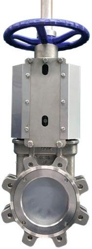
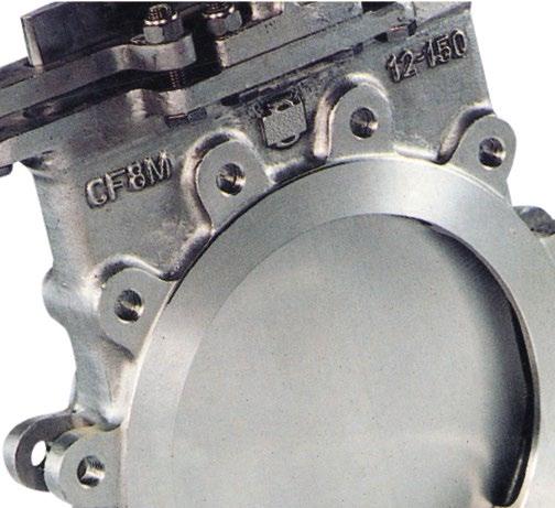
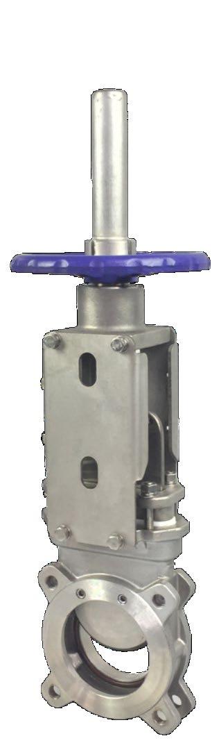
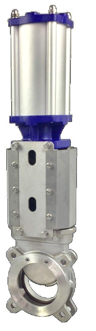
The Flowturn knife gate Series DCNP one-piece, cast body design offers rugged performance in application ranging from general purpose to severe media handling. Available with integral metal or replaceable soft seat, the Flowturn knife gate Series DCNP valve is easily automated for on/off applications. DCNP gate valves are not suitable for Air & Gas or any highly erosive or corrosive or hazardous service. They are also not suitable for low or high temperature service outside of the range shown on our as-built drawings. Resilient seat valves are only suitable for clean liquid service and liquid service with a small degree of impurities or particulates. Any abrasive particles will shorten the life of the resilient seat. PTFE seat potentially provides a longer life than elastomer. The chemical compatibility and temperature limitations of the seat and bonnet seal materials must be considered by the purchaser prior to selection.
Valve features include:
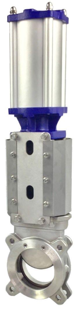
• Top works designed for easy, quick conversion between manual and pneumatic actuation. Manual valves include a lubricant injection port for continuous, smooth operation with minimal maintenance.
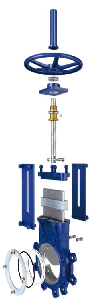
• Clevis design and horizontal bolting stabilises gate ensuring proper alignment.
• Energised quad seal packing for enhanced gland sealing.
• Standard integral metal seat and optional replaceable resilient seats.
• Gate design ensures consistent alignment throughout the length of the stroke.
• Body design with no dead pockets.
SAFETY INFORMATION
The following general safety information should be taken in account in addition to the specific warnings and cautions specified in this manual. They are recommended precautions that must be understood and applied during operation and maintenance of the equipment covered in this I.O.M.
To avoid injury, never attempt disassembly while there are pressures either upstream or downstream. Even when replacing stem packing, caution is necessary to avoid possible injury.
To prevent valve bending, damage, inefficient operation, or early maintenance problems, support piping on each side of the valve.
KNIFE GATE VALVES - DCNP SERIES Australian Pipeline Valve - Installation, Operation and Maintenance Manual 4
In order to avoid personal injury and other types of damage (to property, the plant, etc.), we recommend following these recommendations:
• The personnel responsible for handling and maintenance of the equipment must be qualified and trained in operations with this type of equipment.
• Use appropriate personal protection (gloves, safety boots, goggles, helmet, high-visibility vest...).
• Shut off all operating lines to the valve and put up a warning sign.
• Completely isolate the valve from the whole process.
• Depressurise the process.
• Drain all the line fluid through the valve.
• Use hand tools not electric tools during installation and maintenance.
Before installation, inspect the valve body and components for any possible damage occurred during transport or storage. Make sure that the valve’s inside cavities are clean. Inspect the pipes and the flanges to make sure they contain no foreign material and are clean.
• A valve is a pressurised mechanism containing energised fluids under pressure and consequently should be handled with appropriate care.
• Valve surface temperature may be dangerously too hot or too cold for skin contact.
• Upon disassembly, attention should be paid to the possibility of releasing dangerous and or ignitable accumulated fluids.
• Ensure adequate ventilation is available for service.
This manual provides instructions for storing, general servicing, installation and removal of gate and globe valves.
APV and it’s re sellers refuse any liability for damage to people, property or plant as well as loss of production and loss of income under any circumstances but especially if caused by: Incorrect installation or utilisation of the valve or if the valve installed is not fit for intended purpose. It is the sole responsibility of the user to ensure the valve type and materials are correctly specified.
DURING OPERATION TAKE INTO ACCOUNT THE FOLLOWING WARNINGS:
a- Graphite/Graphoil packing and body gaskets are very brittle, any impacting, twisting or bending should be avoided.
b- The valve’s internal parts such as disc, stem, seats, seals, gaskets shall be handled with care avoiding scratches or surface damage.
c- All tools and equipment for handling the internal parts shall be soft coated.
d- Valves can be fitted with gaskets or seals in PTFE, Buna, EPDM, NBR, Viton, etc., Hence chemicals or high temperatures will damage sealing components and cause seat and bonnet leakage.
e- Never part open valve or part close, gate valves must be full open of full closed to avoid seat damage. Globe valves can be used to throttle (on clean service only) for short periods but must be at least 25% open or else venturi action will damage seating area and body.
For all operations make reference to position number on part list of the applicable drawing listed.
KNIFE GATE VALVES - DCNP SERIES Australian Pipeline Valve - Installation, Operation and Maintenance Manual 5
Packing leakage could result in personal injury. Valve packing is tightened prior to shipping but may require readjustments to meet specific service conditions. Check the temperature and chemical compatibility of bonnet and seat seals.
Never use a DCNP knife-gate for flammable or hazardous liquids or gases. A special bonneted valve with more complex seating design is required for such service.
Personal injury may result from sudden release of any process pressure. APV recommends the use of protective clothing, gloves and eye wear when performing any installation or maintenance.
Isolate the valve from the system and relieve pressure prior to performing maintenance.
Disconnect any operating line providing air pressure, control signals or electrical power to actuators.
Check the packing box for pressurised process fluids even after the valve has been removed from the pipeline, particularly when removing packing hardware or packing rings, or removing packing box pipe plug if fitted.
If a gasket seal is disturbed while removing or adjusting gasketed parts, APV recommends installing a new gasket while reassembling. A proper seal is required to ensure optimum operation.
KNIFE GATE VALVES - DCNP SERIES Australian Pipeline Valve - Installation, Operation and Maintenance Manual 6
1.0 INSTALLATION
Piping should be properly aligned and supported to reduce mechanical loading on the end connections.
The valve must always be installed in the OPEN position.
Verify line is depressurised before installing, removing or repairing a valve or operator.
Do not pressurise the line without an operator on the valve.
The device generates a large mechanical force during normal operation. Observe all applicable safety regulations for valves installed in potentially explosive (hazardous) locations.
1.1 PREPARATION FOR INSTALLATION
1. Remove protective end caps or plugs and inspect valve ends for damage to flange faces.
2. Thoroughly clean adjacent piping system to remove any foreign material that could cause damage to seating surfaces during valve operation.
3. Verify that the space available for installation is adequate to allow the valve to be installed and to be operated.
Ensure sufficient clearance for the stem in the full open position. Inadequate clearance for valves may add mechanical loading to the valve ends. Sufficient clearance should be allowed for threaded end valves to be ‘swung’ during installation.
1.2 INSTALLATION INSTRUCTION
DCNP-B gate valves are Uni-directional, the direction of flow will be indicated on the valve body.
Gate valves should be installed with the stem in a vertical up position on horizontal lines. Never install with the stem below the horizontal axis, as complete drainage is not possible and solids may accumulate in the valve gate sealing area, which will greatly affect the valve operation and service life. If valves are to be installed in vertical lines, please specify at time of order as this is non standard. Refer section 2.0 for more information on orientation.
Reliable support is required for valves with larger diameter (size over DN250), heavy actuator or uncommon positions.
KNIFE GATE VALVES - DCNP SERIES Australian Pipeline Valve - Installation, Operation and Maintenance Manual 7
Note
It is good practice to provide additional support for all pneumatically, hydraulic and electric actuated valves installed in the horizontal stem position. This includes ALL valve sizes due to the fact that many of these installations are located in high vibration areas. Failure to provide additional support will result in premature valve failure.
1. Special care should be taken to maintain the correct distance between the flanges and to ensure that they are parallel to valve body. Incorrect alignment of valve will cause deformations, which can lead to difficulties in operation.
2. Install 2-3 studs on the body button loosely.
3. Insert the appropriate gaskets between valve and pipe flanges. The materials of the gasket is up to the customers selection. Customer can also consult our technicians for suggestions.
4. Place studs in balance positions and tighten evenly in a cross over pattern. Care should be taken when the body drilling cavity studs are tightened to ensure no damage to the valve body. See Appendix A for bolt tightening sequence.
1.3 LIFTING VALVE
Refers to Figures 1 to 8 below on lifting methods for horizontal and vertical lifting.
Do not lift the valve or hold it by the actuator. Lifting the valve by the actuator can lead to operating problems as it is not designed to withstand the valve’s weight.
Do not lift the valve or hold it by the flow passage area. The valve’s seal is located in this area. If the valve is held and lifted by this area it can damage the surface and the O-ring seal and lead to leakage problems whilst the valve is operating.
KNIFE GATE VALVES - DCNP SERIES Australian Pipeline Valve - Installation, Operation and Maintenance Manual 8
FIGURE 1
FIGURE 2
FIGURE 3
FIGURE 4
FIGURE 5
2.0 HANDLING & INSTALLATION
1. Take care in handling valves especially the sealing faces.
2. Make sure that piping and equipment is clean of dust, rust and pipeline scale. Clean all adjoining pipe and fittings. Remove end protector covers from the valves immediately prior to installation. Blow compressed air inside the valves to remove residual dust, dirt, etc., from inside the valves as this could hamper the valves functioning and could also damage the seats.
3. Make joints tight but do not overstress them. This is very important when your tightening gland packing nuts. Always tighten in a diagonal pattern, gradually increasing torque settings.
4. Install valves in the connecting piping so that the arrow mark on the valve body coincides with the flow direction in the pipe.
5. Once the valve has been installed, check that all the screws and nuts have been correctly tightened and that the whole valve action system has been correctly adjusted.
6. Even if the valve has been assembled and tested at APV’s facilities, the screws on the stuffing box may come loose during handling and transport and must be re-tightened.
7. After installation it is advisable to once again flush the piping. Check carefully for visible leaks if any and tighten stem packing and/or bonnet nuts accordingly.
8. If the leakage still persists change the bonnet gasket. Ensure suitable gasket material, we recommend a PTFE bonnet gasket.
9. Flowturn knife gate valves may be installed in agvv b vertical or horizontal pipeline; however the normal method is directly upright relative to the pipeline. Other positions (but ideally no more than 30 degrees from upright) are acceptable; however they may result in uneven valve wear. Above 300NB (12”) we strongly recommend only vertical orientation with the handwheel vertical above the valve body.
10. DCNP valves are uni-directional. The uni-directional valve seals in one flow direction only as indicated by a flow direction arrow on the body. Flow direction is from the opposite side of the seat. The seat is downstream. In rare occasions, it may be advantageous to install the valve with the seat upstream (usually with modification to the valve); contact Flowturn regarding these applications. DCNP-B are bi-directional, refer to separate I.O.M.
KNIFE GATE VALVES - DCNP SERIES Australian Pipeline Valve - Installation, Operation and Maintenance Manual 9
FIGURE 7
FIGURE 6
FIGURE 8
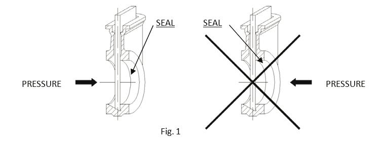
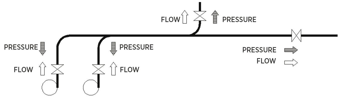
11. As standard, when the valve operates with clean liquids or with low solid content, it is recommended to install it so that the pressure pushes the gate against the seat. That way, the fluid direction will be the same as the direction indicated by the arrow on the body (Fig A).
Please note that the direction of the fluid and pressure do not always coincide (Fig B).
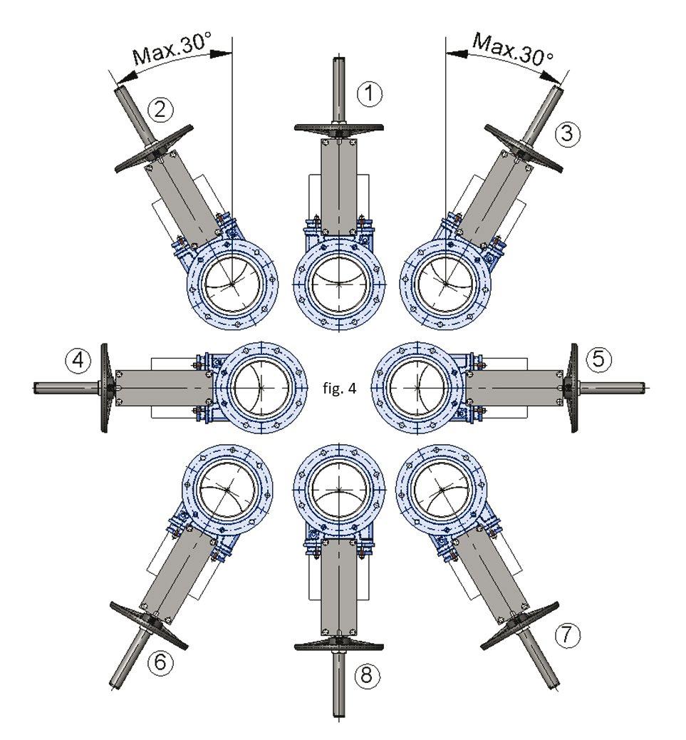
2.1 ASSEMBLY POSITIONS (HORIZONTAL PIPE)
The valves can be assembled in all positions - however see Figure 9 and 10, for recommendations for some of them.
Position 1: This is the most advisable position.
Positions 2 and 3: For standard valves larger than DN150 and maximum installation angle permitted with vertical of 30 degrees.
Positions 4 and 5: For valves larger than DN250, please contact APV. For sizes smaller than DN300 the valves can be installed on an angle of up to 90 degrees in these positions but reduced life may be experienced. It must be stated prior to manufacture.
Positions 6, 7 & 8: Debris accumulation will affect sealing and shorten valve life. To install valves larger than DN150 in any of these positions, please check with APV. It must be stated at time of order prior to manufacture but it is not recommended. In all these positions it is recommended to secure the actuator to prevent the shaft from bending due to the weight of the actuator. If this is not taken into account, it can lead to problems during valve operation.
KNIFE GATE VALVES - DCNP SERIES Australian Pipeline Valve - Installation, Operation and Maintenance Manual 10
FIG. A
FIG. B
1 2 3 4 5 6 7 8
9
FIGURE
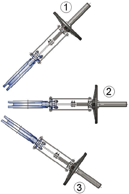
2.2 ASSEMBLY POSITIONS (VERTICAL/LEANING PIPE)
The valves can be assembled in all positions; however, recommendations do exist for some of them, see Figure 10.
Positions 1 & 2: In these positions it is recommended to secure the actuator as its weight can cause the shaft to bend. If this is not taken into account, it can lead to problems during operation. Even then it is only suitable for clean fluid service up to 300NB and manual operation only.
Position 3: Not recommended - special order.
3.0 OPERATION
1. Check visibly for any leaks and re-tighten the joints/glands.
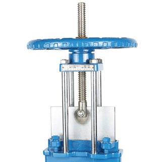
2. Manually operated valves are to be operated through handwheel. To open the valve, turn the handwheel anti-clockwise. To close the valve, turn the handwheel in clockwise direction.
3. Turn the handwheel slowly initially so as to prevent undue stress on the valves due to thermal gradient, water hammering, etc.
4. Never use too much force for either closing or opening the valve, never attempt to apply leverage with a long lever as this could damage yoke nut.
5. Operate the valve with no flow in the pipeline for one cycle to make sure smooth operation.
6. Then test operation and valve seal with flow. When the pressure is increasing gradually to full pressure, there might be minor leakage at packing result from shipping and storage. This can be remedied by tightening the gland follower. The nuts should be tightened gradually and crosswise until the leakage stops.
7. Operate the valve under full pressure for one cycle to test the seal and actuator.
8. If no problem occurs, valve is good for on-off processing.
Knife gate valves are not designed for flow throttling, as this will lead to gate damage.
9. RESILIENT SEATED VALVES – All resilient seated knife gate valves require the resilient seat to be lubricated before stroking, regardless of the type of actuator. The fit pressure of the gate against the resilient seat, on the sides of the valve up through the packing gland, is such that stroking the valve dry, that is with no lubrication of any kind, will cause the resilient seat to cold flow beyond safe limits and will damage the seat with just a few strokes. CRC 6-56™ or WD-40® (Note: Make sure the lubricant used is compatible with the seat material and process media), sprayed on the seat, up in the chest area, on both sides, will normally provide sufficient lubrication. This should be repeated
KNIFE GATE VALVES - DCNP SERIES Australian Pipeline Valve - Installation, Operation and Maintenance Manual 11
1 2
FIGURE 10
3
Note
every 2 or 3 strokes. This is CRITICAL to the life and performance of the seat. In operation, the process product normally supplies adequate lubrication.
10. VALVES WITH OPTIONAL STOPPERS (LOCK CAPS) – After installing resilient seated valves with stoppers, be sure to determine that the stopper and stopper nut are set properly.
a. Remove the stopper nut and stopper.
b. Turn the hand wheel in a clockwise motion until the gate bottoms out.
c. For resilient seated valves, turn the hand wheel an additional 1/4 turn, and then go to step “f”.
d. Turn the hand wheel an additional 1/2 turn counterclockwise.
e. Now freely spin the hand wheel clockwise once, until it stops on its own.
f. Return the stopper and run it down till it meets the wheel nut.
g. Return the stopper nut and run it down tight against the stopper to hold it in position.
11. After the valve has been installed, cycle the valve once completely. Open the valve by turning the hand wheel counter clockwise, reverse the operation for closing. (Note: This will detect if any damage has been incurred due to either shipping or installation processes.) After cycling the gate valve, turn the hand wheel counterclockwise several turns allowing partial opening for preparation to fill system.
12. Open upstream valve slowly, building system pressure gradually, allowing installation personnel to detect any excessive packing gland leakage, making adjustments necessary.
13. After the system has come to full pressure, open the knife gate valve fully by turning the hand wheel
counterclockwise, then close the valve fully by turning the hand wheel clockwise. In resilient seated
knife gate valves, this process will result in “seating in the valve”. This step may be eliminated with the metal seated valve.
14. You may now use the valve for its intended purpose, keeping in mind that a knife gate valve should be used in a full open or full closed position. Knife gate valves should not be used for throttling service unless specifically configured for such use.
4.0 GEAR OPERATORS
The gear operator is lubricated with grease (2% MOS2) for life.
Only in case of failure of any components remove the upper gear casing from lower gear casing. After inspection replace the necessary components.
1. When repairing the drive sleeve and bearing (thrust ball bearing) there should not be any clearance, i.e. the drive should not move axially.
2. Proper installation will correct operation.
KNIFE GATE VALVES - DCNP SERIES Australian Pipeline Valve - Installation, Operation and Maintenance Manual 12
HAND WHEEL HAND WHEEL NUT STOPPER (LOCK CAP) STOPPER (LOCK CAP) NUT
11
FIGURE
Do not dismantle the upper and lower gear casing as it will disturb the whole assembly and the deep groove ball bearings, the operator provided is properly lubricated for long life.
5.0 LEAKAGE
ACROSS SEAT
It is always difficult to ascertain whether there is an internal seat leakage unless there is pressure or leak detection facility in place to monitor any rise or fall in pressure or leakage.
To investigate suspected leakage, the valve should be removed from the line then dismantled. Prior to removal from line ensure all pressure and fluid is purged from line and valve cavity. Remove disc and inspect the seating surfaces, also inspect the body seat for any sign or wire drawing/light scratches.
Relap or replace the seats or gate as required if minor damage or else send the valve to an experienced APV approved valve repair facility. Assemble the valve, should any leaks still persist then the concerned part may need complete replacement.
When ordering spare parts for replacements, kindly inform us the size, type, rating, part description, model number and serial number.
6.0 DISASSEMBLING VALVES
1. Check that the line is in a complete shut down phase.
2. Pre-order all necessary spare gland packings and jointing gaskets.
3. Open the valve slightly by turning the handwheel anti-clockwise and loosen the gland.
4. Remove any process product observing all safety precautions.
5. Put identification markings on valve body, bonnet, disc/gate, yoke, and actuator. This helps to avoid mismatching of parts at the time of re-assembly.
6. If the bolts and nuts are too tight, apply deep penetrating oil and then unscrew.
Also refer to section 10.0 for detailed instructions.
7.0 REASSEMBLY
1. Re-assemble in reverse order of disassembly.
2. For larger valves, lift up the bonnet using lifting lugs where provided. For smaller valves, gently and evenly break the bonnet seat with a lever (if required) before lifting the bonnet off (where required use with a sling mechanical lifting device). Clean gasket surface areas, replace gasket and refit bonnet.
KNIFE GATE VALVES - DCNP SERIES Australian Pipeline Valve - Installation, Operation and Maintenance Manual 13
3. Refer Appendix A for bonnet bolt re-tightening procedure.
4. Before installation do inspection on valve;
a) Make sure the valve body and components are in good condition.
b) Make sure internal cavities of valve body are clean.
c) Make sure corresponding flange and pipe line are free of foreign material.
Also refer to section 10.0 for detailed instructions.
8.0 PREVENTATIVE MAINTENANCE
1. Inspect whether all valves can be opened or closed smoothly at least once a month. If the operation is sluggish, clean the spindle threads and lubricate the same.
2. Check the gland tightening nuts for any leaks or slackness, if required tighten these nuts and ensure that the valve operation is not hampered by over tightening the gland.
3. The manual valve stem should be lubricated at regular intervals with industrial grease for smooth operation of the valve. A lubrication nipple is provided on the collar.
Note, use genuine APV new gland packing sets when replacing.
Do not attempt to repack the stem packing in line while the valve is under pressure. The line must be totally purged. Knife Gate valves do not all have the ‘back seating’ feature. Prior to removing bonnet, exercise extreme caution no pressure is trapped in the valve cavity. Wear appropriate safety apparel and follow industry and plant safety procedures.
9.0 LEAKAGE ACROSS GASKET
Should any body gasket leaks occur, tighten the bolts/nuts & studs (refer Diagram 1, Appendix A). If leakage still persists, the bonnet gasket should be changed.
10.0 MAJOR MAINTENANCE
Only an expert APV approved valve re-conditioner should attempt the following major extraordinary maintenance/repairs. Valve parts are subject to normal wear and must be inspected and replaced as necessary. Inspection and maintenance frequency depends on the severity of the service conditions. This section includes instructions for packing adjustments, repacking, seat replacement and seating adjustment.
KNIFE GATE VALVES - DCNP SERIES Australian Pipeline Valve - Installation, Operation and Maintenance Manual 14
To avoid personal injury to yourself, fellow workers, or damage to property from release of process fluids, before performing any maintenance:
• Shut off all operating lines to the valve.
• Isolate the valve completely from the process.
• Release process pressure.
• Drain the process fluid from the valve.
10.1 NORMAL MAINTENANCE
Normal maintenance of Flowturn knife gate valves may only include a periodic tightening of the packing gland. Should a leak occur at the packing gland, simply tighten the packing gland bolt closest to the leak. This may require tightening two or three bolts on larger valves. After the leak has stopped, tighten all packing gland bolts 1/4 turn. Do not over tighten. The only other normal maintenance required would be to grease the valve stem, by using a grease gun at the grease fitting located on the valve yoke.
1. Grease the valve stem periodically. Rotate the stem protector counter clockwise to take it off. Apply grease to the stem and cycle the valve once.
2. There would be minor leakage at the packing after long term operation. This can be solved by tightening the bolts on gland follower in crosswise pattern.
10.2 PACKING REPLACEMENT
First remove the valve from the line. To prevent injury ensure that all fluid and pressure is removed from the valve both upstream and downstream before removal and disassembly. When removing drain or stem plug wear protective eye masks to avoid injury.
Refer to Appendix C for exploded bill of materials.
1. Depressurise the circuit and place the valve in closed position.
2. Remove the gate guards.
3. From time to time, it may be necessary to repack the valve completely. This can be done following the warning procedure listed above. Standard repacking kits are available from APV. Packing kits include the necessary packing which insures a tight seal. When ordering packing kits, be sure to specify valve model number, seat type, and type of valve. Repacking the valve includes the following steps:
a. Isolate and clear the valve as mentioned in the warning procedure listed above.
b. Remove packing gland nuts and lock washers.
c. Raise blade to full open position.
d. Pull up the packing gland to the top of the blade and secure it to the top of the blade.
e. Using a packing hook, remove all of the old packing.
KNIFE GATE VALVES - DCNP SERIES Australian Pipeline Valve - Installation, Operation and Maintenance Manual 15
CUT BUTTING ENDS AT 45° ANGLES 45°
4. Release stem from the gate.
5. Loosen screws at the bottom of the yoke, and take off actuator of handwheel with yoke connected on.
6. Remove old packing and clean the packing cavity.
7. Insert new packing and tighten the gland follower steadily.
8. Place yoke (with actuator or handwheel mounted on) and screw it on the valve.
9. Connect stem to gate.
10. Mount gate guards.
11. Perform several operation cycles with loaded pipeline and adjust the gland followers to ensure no leakage.
The stem packing system will vary according to valve size, type and class as well as the stem packing material specified.
10.3 SEAT REPLACEMENT
1. Remove valve from pipeline.
2. Take seat retainer off.
3. Remove the old seat and clean the cavity.
4. For metal or PTFE seat, lubricate the o-ring, then place it on the seat groove.
5. Insert the new seat.
6. Mount the seat retainer using the cross-over method.
7. Perform several operation cycles with loaded pipeline to make sure the seal is tight.
8. Soft/metal uni-directional seat replacement.
a. Replace the seats with the valve in the closed position.
b. Remove the retainer ring bolts and slide the assemblies out from both sides of the valve as shown in figure 10.
c. Slide both the seat ring c/w seat backing o-ring of the retainer and o-ring only required for PTFE & metal seat, elastomer seat no required o-ring.
d. Lubricate the replacement o-rings with Syl-Glyde® (NAPA p/n 765-1351 or equivalent) or light grade oil. This will ensure that the o-rings do not roll when placed on the retainer rings, and will also help the installation of the seat assemblies into the valve body.
e. Insert the new seat rings over the o-rings on the retainers.
f. Place the seat retainer assemblies into the valve body and lightly secure with retainer ring bolts.
g. Tighten the retainer ring bolts using the cross-over method described in the installation instructions.
h. Using a straight edge, tighten the bolts till the retainer rings are flush with the valve body as shown in figure 11. Do not over tighten.
KNIFE GATE VALVES - DCNP SERIES Australian Pipeline Valve - Installation, Operation and Maintenance Manual 16
SEAT RING*
RETAINER RING
STRAIGHT EDGE
RETAINER RING SCREW
RETAINER RING
RETAINER RING SCREW BODY
If the gate is removed for any reason, make sure the seat retaining rings are loosened prior to the gate’s reinsertion into the valve body. This will help prevent the seat rings from being damaged.
10.4 GATE REPLACEMENT
1. Perform step 1. to step 5. of packing replacement as shown above in 10.2.
2. Remove seat and gate guide points (right above the valve inlet port).
3. Remove the old gate.
4. Clean body cavity and insert new gate in carefully (no impact with the valve cavity).
5. Re-install the seat.
6. Perform step 6. to 10. of packing replacement as shown above in 10.2.
7. After assembly, re-tighten gate scraper guides.
Do not over tighten bolts. Hydrostatically test the valve to ensure that there is no leakage. Refer to Diagram 1, Appendix A for bolt tightening sequence.
Always be sure that the valve is de-pressurised and isolated prior to performing any maintenance work. Do not attempt to repair valve in-line if volatile, dangerous, hazardous or flammable service. Always wear fully enclosed, splash proof, protective eye wear.
Australian Pipeline Valve - Installation, Operation and Maintenance Manual 17
KNIFE GATE VALVES - DCNP SERIES
FIGURE 10
FIGURE 11
* Supplied with o-ring in metal and PTFE seat, no o-ring required elastomer seat.
11.0 TROUBLESHOOTING
TROUBLE
Packing Leakage
Soft Seated Valve:
In fully close position, seat leakage
High torque during valve seating and unseating
Unable to close or open gate
POSSIBLE CAUSE SOLUTION
> Incompatible media
> Packing deterioration
> Temperature variation
> Normal packing wear
Seat is worn or damaged
Gate is damaged
Entrapped foreign media in pipeline
prohibiting valve from seating
Gate scraper guides too tight
Packing not tighten to recommended torque
Replace packing
a) Remove worn or damaged seat
b) Inspect and clean seat chamber, install new seat
c) Tighten gate scraper guides
Replace gate
Consult factory for proper solutions
a) Remove valve from service
b) Review gate to seat interface
a) Check for valve orientation, flow direction and flow indication
Valve jerks during open and close
Solidified media between body and gate
b) Re-orient valve
c) Replace gate
d) Clean chest area of valve
Superstructure fasteners loosened Tighten the superstructure fasteners
Insufficient air supply
Pneumatic operated valves; increase supply pressure
Solenoid valve dust accumulation Remove and clean solenoid valve
Piston rod seal damaged
Packing is too tight
Replace seal
Loosen packing
KNIFE GATE VALVES - DCNP SERIES Australian Pipeline Valve - Installation, Operation and Maintenance Manual 18
APPENDIX A
BOLTING TORQUE SEQUENCE
DIAGRAM 1
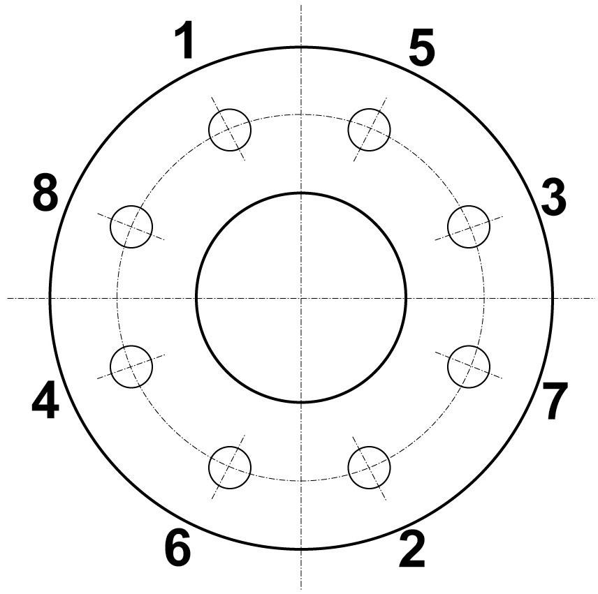
Example only, number of bolts will vary, apply the same criss-cross process, gradually tightening more after each revolution.
Carefully place the valve between the flanges and loosely assemble the valve by putting in the bottom two or three studs, then carefully insert the gaskets into place. The bottom studs will help locate the gasket and hold it in position.
Carefully insert the balance of the studs into place and tighten all of them evenly by using the cross-over pattern. Do not tighten in rotation.
Do not overtighten chest cavity studs.
KNIFE GATE VALVES - DCNP SERIES Australian Pipeline Valve - Installation, Operation and Maintenance Manual 19
Bolting torque sequence: 1 – 2 – 3 – 4 – 5 – 6 – 7 - 8
Typical Cross-over Pattern 1 2 3 4 5 6 7 8 9 10 11 12
APPENDIX B
DESIGN
Flanging
ANSI B16.1/B16.5 125lb/150lb
AS 2129 Table D, E
AS 4087 PN14, PN16
AS 4331.1 PN10, PN16
EN 1092-2 PN10, PN16
ISO 7005-1 PN10, PN16
Pressure/Class Rating
PN10 Rated body.
Long term maximum
packing rating:
10 bar to 250NB
7 bar 300 ~ 450NB
4 bar 500 ~ 600NB
Face to Face Dimensions
AS 6401 & MSS SP-81
Test Standards
MSS SP-71, ISO 5208, MSS SP-61
Pressure/Temperature
Rating Seat
NBR 10 bar -10°C to 90°C
EPDM 10 bar -10°C to 120°C
Viton 10 bar -10°C to 200°C
PTFE 10 bar -10°C to 200°C
Metal to Metal 10 bar -10°C to 200°C
Optional
Stainless
Steel
Safety
Guards (Manual & Actuated Versions)
Resilient seated uni-directional valves are tested leak tight up to 4 Bar (Elastomer) and 2.8 Bar (PTFE) on seat. The Flowturn DCNP is one of the only Knife Gate designs in the world offering a rugged and flexible PTFE seated valve with a tight shut-off. Above 4 Bar rate is estimated at up to 2.66 drops/minute/inch (0.11 drips/minute/DN) as per MSS-SP61. However an actual seat test can be performed above 4.0 Bar if required. Special packing systems and bonnet designs are available for high pressure applications. Flow direction is from the opposite side of the valve for the seat This provides superior shut-off by pressure energizing the gate against the seat and also protects the seat.
KNIFE GATE VALVES - DCNP SERIES Australian Pipeline Valve - Installation, Operation and Maintenance Manual 20
Double Row Thrust Bearings Stainless Steel Fixtures Stainless Steel Stem Cover Adjustable solid tipped PTFE Gate Scraper Guides for tight shut off Hard Chrome Plated Gate for Longer Life Slots to Facilitate Limit Switches Stainless Steel Support Plate Stainless Steel Fixtures Optional Stainless Steel Housing
Aluminium Case Epoxy Coated
Stainless Steel Tie Rods
APPENDIX C
MATERIALS
NO. PART NAME MATERIAL
1 Body CF8M/CF8/WCB+FBE
2 Seat Retainer SS316/SS304/WCB+FBE
2A Seat Retainer Tension Screws A2-70 SS/A4-70 SS
3 Seat Metal STL#6/HCr/NBR/PTFE/ EPDM/Viton
4 Gate SS304/SS316+HCr
5 Adjustable Gate Guide SS304/SS316+Solid PTFE
6 Packing Multi-Layer PTFE Braided+Silicon+PTFE Sheet
7 Bolts A2-70 SS/A4-70 SS
8 Pin SS304
9 Gland CF8M/CF8/WCB+FBE
10 Stem SS304/2CR13
11 Support Plates SS304
12 Bearing Housing SS316/304/WCB+FBE
13 Bearings SS440
14 Bearing Cover SS304
15 Handwheel Epoxy Coated Iron
16 Stem Cover SS304
17 Grease Fitting C95200+2P
18 Safety Guards SS304
20 O-ring* EPDM/NBR/Viton
21 Stem Drive Nut Brass/SS304
* PTFE and metal seat version
- DCNP SERIES Australian Pipeline Valve - Installation, Operation and Maintenance Manual 21
KNIFE GATE VALVES
16 20 2 6 11 10 21 12 15 14 2A 7 13 9 4 3 1 8 5 18 18 17 7 7
5
SEAT AREA GATE TENSION GUIDE GUIDE CLAWS 2 3 20 2A 5
PACKING AREA 6 Silicon Sheet PTFE Sheet Braided PTFE Silicon Laced PTFE Sheet
MATERIAL LIST - MANUAL OPERATED
* Will also fit between Table E flanging all sizes (except 100NB,
KNIFE GATE VALVES - DCNP SERIES Australian Pipeline Valve - Installation, Operation and Maintenance Manual 22
APPENDIX D
NB 50 65 80 100 125 150 200 250 300 350 375 400 450 500 600 L 48 48 51 51 57 57 70 70 76 76 76 89 89 114 114 H 302 345 365 410 460 505 615 740 840 970 1020 1060 1265 1375 1570 PCD 114 127 146 178 210 235 292 356 406 470 495 521 584 641 756 ød1 90 103 122 154 186 211 266 324 378 429 463 489 532 609 720 ød2 60 75 90 105 130 158 210 260 310 360 385 415 465 515 615 n-ød1 2-M16 2-M16 2-M16 2-M16 2-M16 2-M16 2-M16 2-M20 4-M20 4-M24 4-M24 4-M24 4-M24 6-M24 6-M27 n-ød2 2-M16 2-M16 2-M16 2-M16 6-M16 6-M16 6-M16 6-M20 8-M20 8-M24 8-M24 8-M24 8-M24 10-M24 10-M27 h2 ––––––––––––30 15 15 h1 ––––––––––––1810 1950 2205 Materials List Manual Operated AS2129 Table D/AS4087 CL14/16 8 Pin SS304 9 Gland CF8M/CF8/WCB+FBE 3 Seat Metal HCr/NBR/PTFE/EPDM/Viton Retainer 2 Seat SS304/SS316/WCB+FBE Item Part Name Material 1 Body CF8M/CF8/WCB+FBE 4 Gate SS304/SS316+HCr 5 Adjustable Gate Guide Bolt A2-70/A4-70+PTFE 6 Packing Multi Layer PTFE+SI 7 Bolt A2-70 SS/A4-70 SS 10 Stem SS304/2CR13 11 Support Plates SS304 12 Bearing Housing SS304/316/WCB+FBE 13 Bearings SS440 14 Bearing Cover SS304 15 Handwheel Epoxy Coated Iron 16 Stem Cover SS304 17 Grease Fitting C95200 18 Safety Guards SS304 20 O-Ring EPDM/NBR/Viton Assembly 21 Stem Drive Nut Brass/SS304 19 Bevel Gear (Ratio 4.5:1) Dimensions & Weights (MM & KG) –––––––––35 85 50 T 9 11 12 16 20 25 43 62 78 112 145 154 238 265 300 Weight (Kg) Up to 1200NB refer drawing A - A øD2 PCD øD1 NB L 7 8 FLOW 3 2 20 4 2A 9 10 11 ød2 PCD NB ød1 L A - A 7 8 13 FLOW 3 2 4 2A 9 10 17 14 12 16 21 6 11 20 A A h1 n-ød2 n-ød1 T h2 H 19 21 1 16 18 5 n-ød2 H n-ød1 A A 15 18 1 5 15 I G B C 5 6 5 ITEM PART NAME MATERIAL 1 Body CF8M/CF8/WCB+FBE 2 Seat Retainer SS316/SS304/WCB+FBE 2A Seat Retainer Tension Screw A2-70 SS/A4-70 SS 3 Seat Metal STL#6/HCr/NBR/PTFE/EPDM/Viton 4 Gate SS316/SS304+HCr 5 Adjustable Gate Guide Scraper SS + Solid PTFE Tip A2-70/A4-70+PTFE 6 Packing Multi Layer Braided PTFE+Silicon+PTFE Sheet 7 Bolt A2-70 SS/A4-70 SS 8 Pin SS304 9 Gland CF8M/CF8/WCB+FBE 10 Stem SS304/2CR13 11 Support Plates SS304 12 Bearing Housing SS316/SS304/WCB+FBE 13 Bearings SS440 14 Bearing Cover SS304 15 Handwheel Epoxy Coated Iron 16 Stem Cover SS304 17 Grease Fitting C95200 18 Safety Guards SS304 19 Bevel Gear (Ratio 4.5:1) Assembly 20* O-Ring* EPDM/NBR/Viton 21 Stem Drive Nut Brass/SS304 * Metal and PTFE seat version only. DIMENSIONS & WEIGHTS (MM & KG) AS 2129 Table D*/AS 4087 CL14/16 NB 50 65 80 100 125 150 200 250 300 350 375 400 450 500 600 L 48 48 51 51 57 57 70 70 76 76 76 89 89 114 114 H 302 345 365 410 460 505 615 740 840 970 1020 1060 1265 1375 1570 PCD 114 127 146 178 210 235 292 356 406 470 495 521 584 641 756 ød1 90 103 122 154 186 211 266 324 378 429 463 489 532 609 720 ød2 60 75 90 105 130 158 210 260 310 360 385 415 465 515 615 n-ød1 2-M16 2-M16 2-M16 2-M16 2-M16 2-M16 2-M16 2-M20 4-M20 4-M24 4-M24 4-M24 4-M24 6-M24 6-M27 n-ød2 2-M16 2-M16 2-M16 2-M16 6-M16 6-M16 6-M16 6-M20 8-M20 8-M24 8-M24 8-M24 8-M24 10-M24 10-M27 h2 ––––––––––––30 15 15 h1 ––––––––––––1810 1950 2205 Materials List Manual Operated AS2129 Table D/AS4087 CL14/16 8 Pin SS304 9 Gland CF8M/CF8/WCB+FBE 3 Seat Metal HCr/NBR/PTFE/EPDM/Viton Retainer 2 Seat SS304/SS316/WCB+FBE Item Part Name Material 1 Body CF8M/CF8/WCB+FBE 4 Gate SS304/SS316+HCr 5 Adjustable Gate Guide Bolt A2-70/A4-70+PTFE 6 Packing Multi Layer PTFE+SI 7 Bolt A2-70 SS/A4-70 SS 10 Stem SS304/2CR13 11 Support Plates SS304 12 Bearing Housing SS304/316/WCB+FBE 13 Bearings SS440 14 Bearing Cover SS304 15 Handwheel Epoxy Coated Iron 16 Stem Cover SS304 17 Grease Fitting C95200 18 Safety Guards SS304 20 O-Ring EPDM/NBR/Viton Assembly 21 Stem Drive Nut Brass/SS304 19 Bevel Gear (Ratio 4.5:1) Dimensions & Weights (MM & KG) ` ` –––––––––35 85 50 T 9 11 12 16 20 25 43 62 78 112 145 154 238 265 300 Weight (Kg) Up to 1200NB refer drawing A - A øD2 PCD øD1 NB L 7 8 FLOW 3 2 20 4 2A 9 10 11 ød2 PCD NB ød1 L A - A 7 8 13 FLOW 3 2 4 2A 9 10 17 14 12 16 21 6 11 20 A A h1 n-ød2 n-ød1 T h2 H 19 21 1 16 18 5 n-ød2 H n-ød1 A A 15 18 1 5 15 I G B C 5 6 5 NB L H PCD øD1 øD2 n-ød1 n-ød2 h1 h2 T Weight 50 48 302 114 90 60 2-M16 2-M16 - - - 9.0 65 48 345 127 103 75 2-M16 2-M16 - - - 11.0 80 51 365 146 122 90 2-M16 2-M16 - - - 12.0 100 51 410 178 154 105 2-M16 2-M16 - - - 16.0 125 57 460 210 186 130 2-M16 6-M16 - - - 20.0 150 57 505 235 211 158 2-M16 6-M16 - - - 25.0 200 70 615 292 266 210 2-M16 6-M16 - - - 43.0 250 70 740 356 324 260 2-M20 6-M20 - - - 62.0 300 76 840 406 378 310 4-M20 8-M20 - - - 78.0 350 76 970 470 429 360 4-M24 8-M24 - - - 112.0 375 76 1020 495 463 385 4-M24 8-M24 - - - 145.0 400 89 1060 521 489 415 4-M24 8-M24 - - - 154.0 450 89 1810 584 532 465 4-M24 8-M24 1265 30 35 238.0 500 114 1950 641 609 515 6-M24 10-M24 1375 15 85 265.0 600 114 2205 756 720 615 6-M27 10-M27 1570 15 50 300.0 700 114 - 845 809 710 8-M27 12-M27 1710 15 50 510.0 750 114 - 927 888 725 8-M30 12-M30 1820 15 50 580.0 800 114 - 984 942 790 8-M33 12-M33 1950 15 50 640.0 900 114 - 1092 1050 860 10-M33 14-M33 2100 15 50 850.0 1000 114 - 1175 1133 980 10-M33 14-M33 2300 15 50 1100.0 1200 114 - 1410 1368 1180 14-M33 18-M33 2650 15 50 1680.0
250NB, 450NB)
KNIFE GATE
DCNP SERIES Australian Pipeline Valve - Installation, Operation and Maintenance Manual 23
Dimensions & Weights Actuated Valve (MM & KG) 18 16 20 19 14 17 15 7 4 8 11 B 1 3 5 2 6 9 10 12 13 NB 50 65 80 100 125 150 200 250 300 350 375 400 450 500 600 H 457 505 545 615 680 760 950 1135 1320 1510 1610 1650 1850 2010 2300 W 100 100 120 120 150 150 195 240 280 280 395 395 395 423 423 Cylinder Bore 80 80 100 100 125 125 160 200 250 250 280 300 300 320 320 Stroke 60 75 85 105 135 160 210 260 310 360 410 410 460 510 610 Air Connect F1/4 F1/4 F1/4 F1/4 F1/4 F3/8 F3/8 F3/8 F3/8 F3/8 F3/8 F3/8 F3/8 F3/8 F3/8 Cylinder Weight 6.3 6.3 6.3 6.3 9.2 9.2 26.0 39.0 60.0 98.0 103.0 103.0 126.0 136.0 146.0 Valve & Actuator Weight 15.0 17.0 18.0 22.0 29.0 34.0 69.0 101.0 138.0 210.0 230.0 250.0 310.0 347.0 392.0 Refer to APV sizing guide, large cylinder may be requiring air supply 4 bar to 7 bar Exploded View 1/4” Air Connection A - A øD2 PCD øD1 NB L n-ød2 n-ød1 A 12 Cover Caps Epoxy Coated Steel Epoxy Coated Steel 13 Tie Rod A2-70 SS A2-70 SS 16 Bolt A2-70 SS A2-70 SS 15 Scraper Seal PTFE PTFE 14 Seal Retainer SS304 SS304 17 O-Ring NBR/Viton NBR/Viton 19 Shaft Bearing Brass Brass 20 Shaft Seal Polyurethane Polyurethane 18 O-Ring NBR/EPDM/Viton NBR/EPDM/Viton FLOW Uni-Directional FLOW Bi-Directional MATERIAL LIST - DOUBLE ACTING ACTUATED VALVE ITEM PART NAME 50mm~300mm 400mm & Above 1 Piston Rod 1045+Hardchrome/304SS 1045+Hardchrome/304SS 2 Bottom Cover Epoxy Coated Steel Epoxy Coated Steel 3 Wear Ring PTFE+Cu PTFE+Cu 4 O-Ring NBR/Viton NBR/Viton 5 O-Ring NBR/Viton NBR/Viton 6 O-Ring NBR/Viton NBR/Viton 7 Piston Aluminium Alloy Cr Plated 1045 8 Cylinder Tube Aluminium Alloy Cr Plated 1045 9 Bolt A2-70 A2-70 10 O-Ring NBR NBR 11 Stroke Adjuster A2-70 SS A2-70 SS 12 Cover Caps Epoxy Coated Steel Epoxy Coated Steel 13 Tie Rod A2-70 SS A2-70 SS 14 Seal Retainer SS304 SS304 15 Scraper Seal PTFE PTFE 16 Bolt A2-70 SS A2-70 SS 17 O-Ring NBR/Viton NBR/Viton 18 V-Ring Polyurethane Polyurethane 19 Shaft Bearing Brass Brass 20 Shaft Seal EPDM/NBR/Viton EPDM/NBR/Viton * Metal and PTFE version only. DIMENSIONS & WEIGHTS - ACTUATED VALVE (MM & KG) Materials List Double Acting Actuator Dimensions & Weights Actuated Valve (MM & KG) 18 11 10 12 13 NB 50 65 80 100 125 H 457 505 545 615 680 W 100 100 120 120 150 Cylinder Bore 80 80 100 100 125 Stroke 60 75 85 105 135 Air Connect F1/4 F1/4 F1/4 F1/4 F1/4 Cylinder Weight 6.3 6.3 6.3 6.3 9.2 Valve & Actuator Weight 15.0 17.0 18.0 22.0 29.0 Exploded View B A - A øD2 PCD øD1 NB L A - A H n-ød2 n-ød1 W A A Item Part Name 50mm~300mm 2 Bottom Cover Epoxy Coated Steel Epoxy Coated Steel 1 Piston Rod Steel+Hardchrome Steel+Hardchrome 4 O-Ring NBR/Viton NBR/Viton 3 Wear Ring PTFE+Cu PTFE+Cu 7 Piston Aluminium Alloy Cr Plated WCB 6 O-Ring NBR/Viton NBR/Viton 9 Bolt A2-70 A2-70 8 Cylinder Tube Aluminium Alloy Cr Plated WCB 10 O-Ring NBR NBR 12 Cover Caps Epoxy Coated Steel Epoxy Coated Steel 11 Stroke Adjuster A2-70 SS A2-70 SS 13 Tie Rod A2-70 SS A2-70 SS 16 Bolt A2-70 SS A2-70 SS 15 Scraper Seal PTFE PTFE 14 Seal Retainer SS304 SS304 17 O-Ring NBR/Viton NBR/Viton 19 Shaft Bearing Brass Brass 20 Shaft Seal Polyurethane Polyurethane 18 O-Ring NBR/EPDM/Viton NBR/EPDM/Viton 350mm & ABOVE 5 Adjustable Gate Guide Bolt A2-70/A4-70+PTFE A2-70/A4-70+PTFE 13 FLOW Uni-Directional FLOW Bi-Directional NB H W Cylinder Bore Stroke Air Connect Cylinder Weight Valve & Actuator Weight 50 457 100 80 60 F1/4 6.3 15.0 65 505 100 80 75 F1/4 6.3 17.0 80 545 120 100 85 F1/4 6.3 18.0 100 615 120 100 105 F1/4 6.3 22.0 125 680 150 125 135 F1/4 9.2 29.0 150 780 150 125 160 F3/8 9.2 34.0 200 950 195 160 210 F3/8 26.0 69.0 250 1135 240 200 260 F3/8 39.0 101.0 300 1320 280 250 310 F3/8 60.0 138.0 350 1510 395 300 360 F3/8 103.0 215.0 375 1610 395 300 410 F3/8 103.0 230.0 400 1650 395 300 410 F3/8 103.0 250.0 450 2005 423 350 460 F3/8 136.0 320.0 500 2285 423 350 510 F3/8 138.0 360.0 600 2385 440 400 610 F3/8 146.0 392.0 Refer to APV sizing guide. Air supply 4 bar to 7 bar Materials List Double Acting Actuator Dimensions & Weights Actuated Valve (MM & KG) 18 16 20 19 14 17 15 7 4 8 11 B 1 3 5 2 6 9 10 12 13 NB 50 65 80 100 125 150 200 250 300 350 375 400 450 500 600 H 457 505 545 615 680 760 950 1135 1320 1510 1610 1650 1850 2010 2300 W 100 100 120 120 150 150 195 240 280 280 395 395 395 423 423 Cylinder Bore 80 80 100 100 125 125 160 200 250 250 280 300 300 320 320 Stroke 60 75 85 105 135 160 210 260 310 360 410 410 460 510 610 Air Connect F1/4 F1/4 F1/4 F1/4 F1/4 F3/8 F3/8 F3/8 F3/8 F3/8 F3/8 F3/8 F3/8 F3/8 F3/8 Cylinder Weight 6.3 6.3 6.3 6.3 9.2 9.2 26.0 39.0 60.0 98.0 103.0 103.0 126.0 136.0 146.0 Valve & Actuator Weight 15.0 17.0 18.0 22.0 29.0 34.0 69.0 101.0 138.0 210.0 230.0 250.0 310.0 347.0 392.0 Refer to APV sizing guide, large cylinder may be requiring air supply 4 bar to 7 bar Exploded View B 1/4” Air Connection A - A øD2 PCD øD1 NB L A - A H n-ød2 n-ød1 W A A Item Part Name 50mm~300mm 2 Bottom Cover Epoxy Coated Steel Epoxy Coated Steel 1 Piston Rod Steel+Hardchrome Steel+Hardchrome 4 O-Ring NBR/Viton NBR/Viton 3 Wear Ring PTFE+Cu PTFE+Cu 7 Piston Aluminium Alloy Cr Plated WCB 6 O-Ring NBR/Viton NBR/Viton 9 Bolt A2-70 A2-70 8 Cylinder Tube Aluminium Alloy Cr Plated WCB 10 O-Ring NBR NBR 12 Cover Caps Epoxy Coated Steel Epoxy Coated Steel 11 Stroke Adjuster A2-70 SS A2-70 SS 13 Tie Rod A2-70 SS A2-70 SS 16 Bolt A2-70 SS A2-70 SS 15 Scraper Seal PTFE PTFE 14 Seal Retainer SS304 SS304 17 O-Ring NBR/Viton NBR/Viton 19 Shaft Bearing Brass Brass 20 Shaft Seal Polyurethane Polyurethane 18 O-Ring NBR/EPDM/Viton NBR/EPDM/Viton 350mm & ABOVE 5 Adjustable Gate Guide Bolt A2-70/A4-70+PTFE A2-70/A4-70+PTFE 13 FLOW Uni-Directional FLOW Bi-Directional
VALVES -
APPENDIX E
APPENDIX F
SEAT & CYLINDER SELECTION
RESILIENT SEAT SERVICE APPLICATIONS
The following is general information and materials required for special application should be specified.
For slurry service next size up is required, lease consult us. Special slurry design valve required.
KNIFE GATE VALVES - DCNP SERIES Australian Pipeline Valve - Installation, Operation and Maintenance Manual 24
Common Name ASTM Code Max. Temp Mild Abrasion Aging Water Resistance Oil Resistance Solvent Strong Acid Weak Acid Strong Alkali Weak Alkali Buna-N/NBR NBR 93°C Ø o tØ Ø o ~ X X Ø Ø Ø Neoprene CR 93°C Ø Ø Ø o X X o Ø Ø Natural Rubber NR 65°C Ø Ø Ø X X X Ø Ø Ø EPT EPDM 121°C Ø Ø Ø X X r o r Ø Silicon Si 160°C Ø Ø Ø X ~ o o X Ø Ø Ø Viton FPM 160°C o o Ø* Ø Ø Ø* Ø Ø Ø PTFE D-1457 160°C Ø** Ø Ø Ø Ø Ø Ø Ø Ø * Cold only, not hot. **High impact resistant. Note: Ø Excellent, o Good, r Fair, X Poor SIZING INFORMATION FOR HEAVY DUTY AIR CYLINDER OPERATOR DC SERIES Cylinders for air, oil and water for Knife Gate Valves with line differential pressures of 276 kPa through 552 kPa. This is a rough estimatings guide. Sizes shown is the bore of the cylinder. Actuator Air Supply 276 kPa. Air 345 kPa. Air 414 kPa. Air 483 kPa. Air 552 kPa. Air 621 kPa. Air 689 kPa. Air Valve Size (mm) Valve Size (in) Cylinder Size Cylinder Size Cylinder Size Cylinder Size Cylinder Size Cylinder Size Cylinder Size M R M R M R M R M R M R M R 80 3” 102 100 100 100 76 76 76 76 76 76 64 64 64 64 100 4” 127 127 127 127 100 100 100 100 100 100 100 100 76 76 150 6” 152 152 152 152 125 125 125 125 125 125 125 125 100 100 200 8” 200 200 200 200 200 200 152 152 152 152 152 152 127 127 250 10” 254 254 250 250 200 200 200 200 200 200 200 200 150 150 300 12” 305 305 250 250 250 250 250 250 200 200 200 200 200 200 350 14” 356 356 300 300 300 300 250 250 250 250 250 250 200 200 400 16” 406 406 350 350 300 300 300 300 250 250 250 250 250 250 450 18” 406 406 400 400 350 350 300 300 300 300 300 300 250 250 500 20” 400 400 400 400 350 350 350 350 300 300 300 300 600 24” 400 400 400 400 350 350 350 350 “M” indicates metal-seated valve “R” indicates one side DCNP resilient-seated valve This is a “ready reckoner” for ‘DCNP” series - but is a guide only. Cylinder size varies depending on model, pressure, seat type, configuration and media. Service viscocity and other factors can dramatically effect sizing. DCNP Actuator air supply .41 ~ .585 mpa operating minimum .375 mpa maximum .7 mpa
WARRANTY
1. LIMITED WARRANTY: Subject to the limitations expressed herein, Seller warrants that products manufactured by Seller shall be free from defects in design, material and workmanship under normal use for a period of one (1) year from installation but in no case shall the warranty period extend longer than eighteen months from the date of sale. This warranty is void for any damage caused by misuse, abuse, neglect, acts of God, or improper installation. For the purpose of this section, “Normal Use”
means in strict accordance with the installation, operation and maintenance manual. The warranty for all other products is provided by the original equipment manufacturer.
2. REMEDIES: Seller shall repair or replace, at its option, any non-conforming or otherwise defective product, upon receipt of notice from Buyer during the Manufacturer’s warranty period at no additional charge. SELLER HEREBY DISCLAIMS ALL OTHER EXPRESSED OR IMPLIED WARRANTIES, INCLUDING, WITHOUT LIMITATION, ALL IMPLIED WARRANTIES OF MERCHANTABILITY AND FITNESS OR FITNESS FOR A PARTICULAR PURPOSE.
3. LIMITATION OF LIABILITY: UNDER NO CIRCUMSTANCES SHALL EITHER PARTY BE LIABLE TO THE OTHER FOR INCIDENTAL, PUNITIVE, SPECIAL OR CONSEQUENTIAL DAMAGES OF ANY KIND. BUYER HEREBY ACKNOWLEDGES AND AGREES THAT UNDER NO CIRCUMSTANCES, AND IN NO EVENT, SHALL SELLER’S LIABILITY, IF ANY, EXCEED THE NET SALES PRICE OF THE DEFECTIVE PRODUCT(S) PURCHASED DURING THE PREVIOUS CONTRACT YEAR.
4. LABOUR ALLOWANCE: Seller makes NO ADDITIONAL ALLOWANCE FOR THE LABOUR OR EXPENSE OF REPAIRING OR REPLACING DEFECTIVE PRODUCTS OR WORKMANSHIP OR DAMAGE RESULTING FROM THE SAME.
5. RECOMMENDATIONS BY SELLER: Seller may assist Buyer in selection decisions by providing information regarding products that it manufacturers and those manufactured by others. However, Buyer acknowledges that Buyer ultimately chooses the product’s suitability for its particular use, as normally signified by the signature of Buyer’s technical representative. Any recommendations made by Seller concerning the use, design, application or operation of the products shall not be construed as representations or warranties, expressed or implied. Failure by Seller to make recommendations or give advice to Buyer shall not impose any liability upon Seller.
6. EXCUSED PERFORMANCE: Seller will make a good faith effort to complete delivery of the products as indicated by Seller in writing, but Seller assumes no responsibility or liability and will accept no back-charge for loss or damage due to delay or inability to deliver, caused by acts of God, war, labour difficulties, accidents, inability to obtain materials, delays of carriers, contractors or suppliers or any other causes of any kind whatever beyond the control of Seller. Under no circumstances shall Seller be liable for any special, consequential, incidental, or indirect damages, losses, or expense (whether or not based on negligence) arising directly or indirectly from delays or failure to give notice of delay.
KNIFE GATE VALVES - DCNP SERIES Australian Pipeline Valve - Installation, Operation and Maintenance Manual 25

AUSTRALIANPIPELINEVALVE®HEADOFFICE 70-78StanbelRoadSalisburyPlainSouthAustralia5109Telephone+61(0)882850033 www.australianpipelinevalve.com.au If you have any requirements in the field of valves, please contact us for a prompt response. Continuous development of Australian Pipeline Valve products may necessitate changes in the design or manufacture process. Australian Pipeline Valve reserves the right to effect any such changes without prior notice. © Australian Pipeline Valve 1990 - 2024 Edition LOCAL DISTRIBUTOR/AGENT IOM Flowturn Knife Gate - DCNP
