“Australian Pipeline Valve produces isolation, control and flow reversal protection products for severe and critical service media in utility, steam, pipelines, oil & gas and process industries. APV valves and pipeline products form the most competitive portfolio in the market.”
APV FAMILY OF BRANDS RANGE - CATALOGUES
Oilfield Products Valves & Wellheads
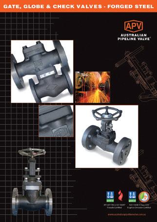
Gate, Globe & Check Valves - Forged Steel
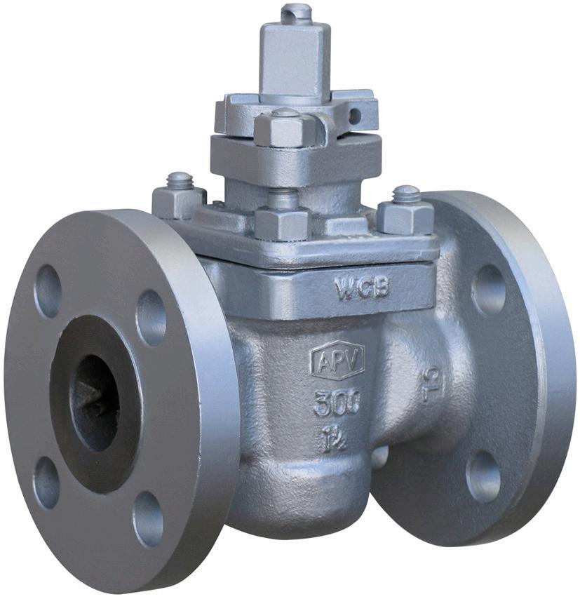
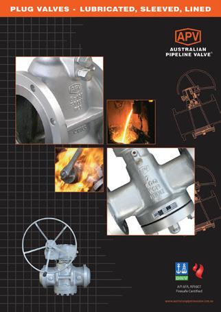
Plug Valves Lubricated, Sleeved & Lined
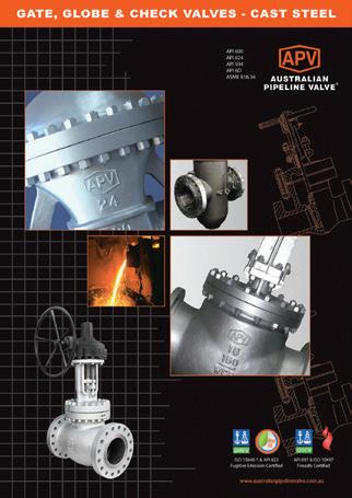
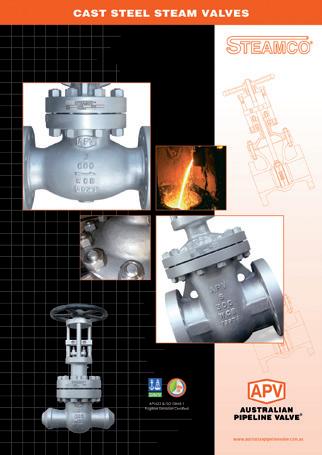
Gate, Globe & Check Valves - Cast Steel
Diamond Gear Gearboxes
Flowturn Gate, Globe & Check Valves
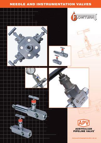
Flowturn Instrument Valves
Flowturn Ball Valves Multiway & Deadman
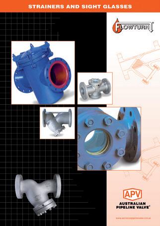
Flowturn Strainers & Sight Glasses
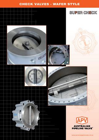
Supercheck Wafer Check Valves
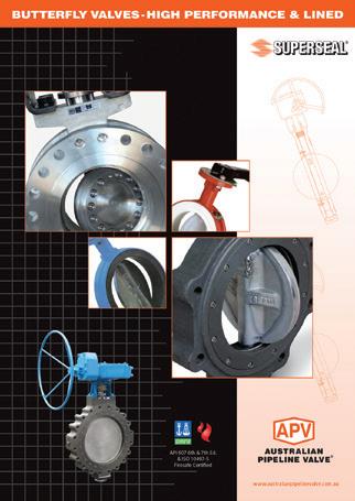
Superseal Butterfly Valves
Steamco Steam Valves
Superseal
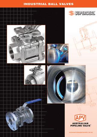
Industrial Ball Valves
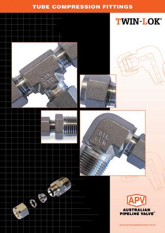
TwinLok Tube Fittings
Uniflo Check Valves
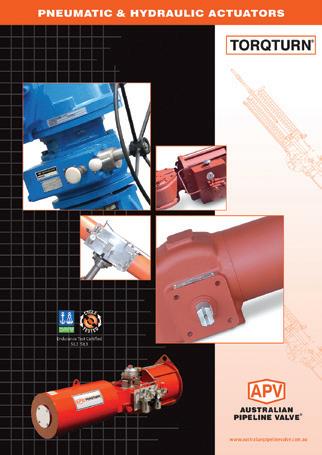
Torqturn Actuators
Ball Valves Floating & Trunnion Mounted
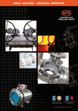
Ball Valves Floating Small Bore Ball Valves Special Service
Product Brochure
INTRODUCTION
The majority of this information is common knowledge to experienced steel valve users. When properly installed in applications for which they were designed, APV valves will give long trouble free service. This instruction is only a guide for installation, operation and minor maintenance. A professional APV approved valve engineering facility should be utilised for reconditioning and minor repairs.
Note
We do recommend however that this entire document be read prior to proceeding with any installation or repair. Australian Pipeline Valve and it’s parent company take no responsibility for damage or injury to people, property or equipment. It is the sole responsibility of the user to ensure only specially trained valve repair experts perform repairs under the supervision of a qualified supervisor.
RESPONSIBILITY FOR VALVE APPLICATION
The User is responsible for ordering the correct valves. APV Valves are to be installed in the observance of the pressure rating and design temperature. Prior to installation, the valves and nameplates should be checked for proper identification to be sure the valve is of the proper type, material and is of a suitable pressure class and temperature limit to satisfy the applications requirements.
Do not use any valve in applications where either the pressure or temperature is higher than the allowable working values. Also valves should not be used in service media if not compatible with the valve material of construction, as this will cause chemical attacks.
RECEIVING INSPECTION AND HANDLING
Valves should be inspected upon receipt to determine:
- Compliance to purchase order requirements.
- Correct type, pressure class, size, body and trim materials and end connections (this information may be found on the nameplate or may be stamped on the body of the valve).
- Any damaged caused during shipping and handling to end connections, hand wheel or stem.
The End User is advised that misapplication of the product may result in injuries or property damage. A selection consistent with the particular performance requirements is important for proper application and is the sole responsibility of the end user.
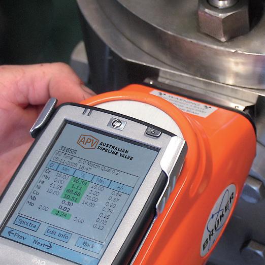
MATERIAL COMPATIBILITY
Valve structural materials and lubricants should be chemically compatible with other piping system components, line fluids, and the environment. If compatibility is a concern, guidance should be sought from appropriate sources (system engineers for example).
SAFETY INFORMATION
The following general safety notices supplement the specific warnings and cautions appearing elsewhere in this manual. They are recommended precautions that must be understood and applied during operation and maintenance of the equipment covered herein.
Do not attempt to disassemble a valve while there is pressure in the line. Make sure both upstream and downstream pressures are removed. Disassemble with caution in case all pressures are not relieved. Even when replacing packing rings, caution is necessary to avoid possible injury.
To prevent valve distortion, inefficient operation, or early maintenance problems, support piping on each side of the valve. Warning, certain gases and fluids could cause damage to human health, the environment or property, hence the necessary safety precautions to prevent risk should be taken.
• A valve is a pressurised device containing energised fluids and should be handled with appropriate care.
• Valve surface temperature may be dangerously too hot or too cold for skin contact.
• Upon disassembly, attention should be paid to the possibility of releasing dangerous and or ignitable accumulated fluids.
• Adequate ventilation should be available for service
This manual provides instructions for storing, general servicing, installation and removal of plug valves. APV refuses any liability for damage to people, property or plant as well as loss of production and loss of income under any circumstances but especially if caused by: Incorrect installation or utilisation of the valve or if the valve installed is not fit for intended purpose. It is the sole responsibility of the client to ensure the valve type and materials are correctly specified.
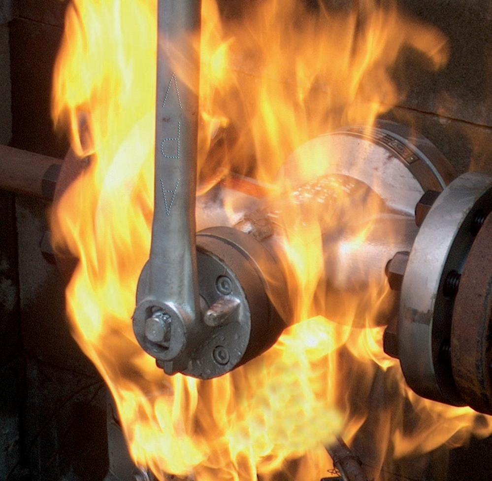
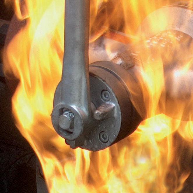
FIRE SAFETY
The term “firesafe” is nebulous and should not be used without an accompanying specification of what exactly may be required. For example there may be a requirement for a specific test, or for limitations on the failure mode of the valve to be identified.
Examples include:
• Gross valve pressure boundary leakage caused by the destruction of elastomeric or polymeric materials.
• Leakage greater than a specific rate when the valve is closed caused by destruction of elastomeric or polymeric.
• Uncontrolled build up of pressure in the body cavity of a double-seated valve causing external heating of the valve.
PRESSURE BUILD-UP
Expansion or vaporisation of the liquid will increase the cavity when a closed valve containing liquid is heated (e.g. from process condition, radiation, or solar heating). Alternately, cooling an undrained cavity below freezing point may also result in expansion of the medium. These expansions can result in extremely high pressures in the valve. Consideration should be given to providing positive measures for the prevention of such pressurisation when these conditions are predicted.
A pressure-relief device is not provided to pressure balanced plug valves to protect them from excessive pressurisation from line pressure. The onus is on the user to provide a pressure relief device as part of the line system in which the valve will be used.
OTHER PRESSURISATION
Pressure balanced plug valves are not provided with a pressure-relief device to protect them from over pressurisation from line pressure. It is the user’s responsibility to provide a relief device as part of the line system in which the valve will be used.
CHANGES TO TEMPERATURE
Valve structural materials expand with rising temperatures and contract with falling temperatures. Increases in temperature cause a decrease of mechanical strength that is generally regained on return to a lower temperature. Significant thermal stresses or distortion, with possible adverse effect on valve performance, may be caused by nonuniform temperature in a structure.
Thermal stress fatigue is a possibility and should be considered in applications involving frequent temperature cycling. One, or a combination, of the following, may increase the possibility:
• Increasing thickness of metal sections.
• Increasing rate of temperature change.
• Increasing thermal conductivity of the fluid.
• Increasing temperature level.
• Increasing temperature range.
• Increasing the number of cycles.
Thermal cycling may also increase the tendency for stem seal leakage.
OCCUPATIONAL HEALTH & SAFETY
When installing or maintaining valves:
a) Ensure all site Work Safety Rules are observed in particular permit to work and hot work procedures.
b) As necessary ensure personal protective equipment/clothing is worn.
c) Eliminate or reduce hazards to an acceptable level by conducting a risk assessment.
d) Ensure the line has been fully drained and de-pressurised before removing a valve, maintain a joint, or loosen or remove any fastening or fitting.
e) Work in accordance with safe systems of work.
f) Valves that have been used on harmful substances should never by handled unless they have been completely decontaminated and certified safe.
g) Operate the valve in the open position to ensure no trapped pressure exists within the cavity.
h) A professional APV approved valve engineering facility should be utilised for reconditioning and minor repairs to any valve.
i) A valve should never be used in any application where it exceeds its prescribed operating parameters. Refer to APV for performance information.
j) Due to the large physical size and weight of some valves, always use correct lifting methods when installing, removing and maintaining the product: Use all of the lifting lugs on the body when available; Valves without lifting lugs - use chains or slings wrapped around the body. Do not attempt to lift the valve using the sealant fittings, gear unit, handwheel, actuator, wrench, or the tapped hole in the end of the stem.
Always ensure that the valve and operator assembly are adequately supported in their final operating location.
k) The valve wrenches are only intended for valve operation and must not be used to carry them. Failure to comply could result in operator injury.
l) APV should be consulted prior to equipment intended for installation in areas which may be subject to seismic activity or extreme climatic conditions.
m) Due to the various applications of which this product can be used, it is the responsibility of the end user to ensure the compatibility of the media with the materials of construction of the product for each specific duty (i.e. Corrosion and erosion which may affect the integrity of the pressure containing envelope).
n) If the product is used in an environment likely to cause extreme temperatures (high or low) that could cause injury to personnel if touched, then adequate insulation/ protection must be fitted. It is recommended that the insulation allows easy access for maintenance, to the sealant fittings, and to the valve operator.
0) If the equipment is to be used on unstable gas duty, ensure that the operational parameters as indicated on the product identification plate are not exceeded.
p) This equipment must be installed in a system that is designed to prevent excessive forces acting on the flanges, connections, etc.
q) This equipment should be protected by other devices to prevent over-pressurisation. (i.e. Caused by external fire, etc).
r) Lethal Service. In accordance with the design verification code (ASME Boiler and Pressure Vessel Code Section VIII Division 1) a casting quality factor of 1.0 is allowable for all products except those intended for ‘lethal service’. All products for such service must have had nondestructive examination carried out in accordance with Appendix 7 of the code. Refer to APV.
s) End Flanges: The end flange design of this product has been verified by either:
ASME Boiler and Pressure Vessel Code Section VIII Division 1 calculation method; Finite Element Analysis in accordance with ASME Boiler and Pressure Vessel Code Section VIII
Division 2 - Alternative rules;
Experimental testing as defined in BS EN 12516-3, Valve Design Strength - Part 3 Experimental Method. Gaskets: The gaskets used in all methods are Spiral Wound to BS EN 1514-2 for PN rated Flanges and ASME B16.20 for Class rated flanges. These have Gasket Factors and Design Stresses of 2.5 and 10000 psi respectively for Carbon Steel gaskets, and 3.0 and 10000 psi respectively for Stainless Steel gaskets, as defined in the ASME Boiler and Pressure Vessel Code Section VIII Division 1. If gaskets are used with higher Gasket Factors and Design Stresses than those stated above, please consult APV.
Bolting: End flanges for steel valves have been verified by the methods stated above, using bolt design stress values based on those for ASTM A193 B7, B7M, B8, B8M as defined in ASME Boiler and Pressure Vessel Code Section II - Materials - Part D - Properties.
Flanged CAST IRON plug valves have flat faced flanges for use with full face across gaskets.
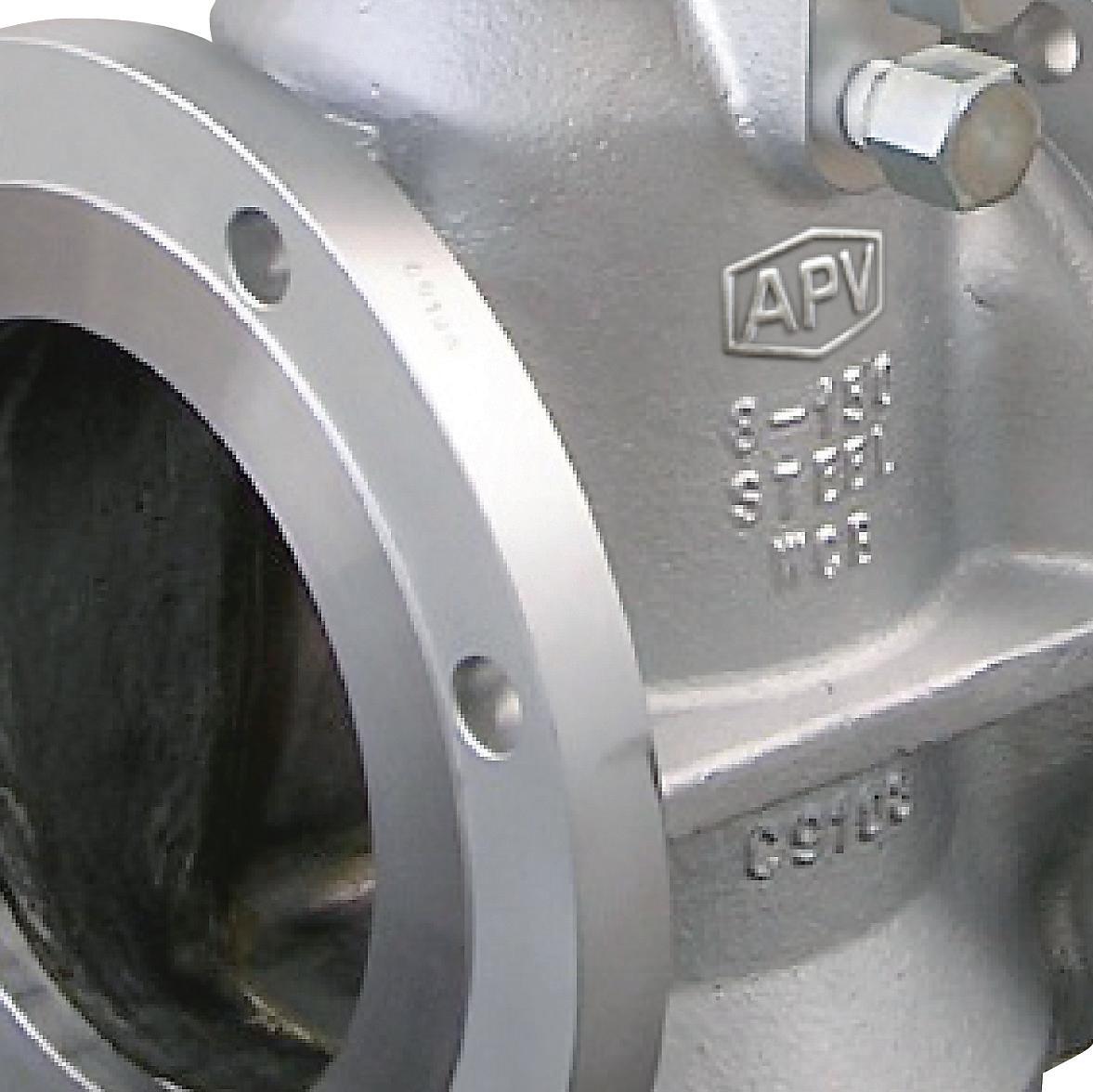
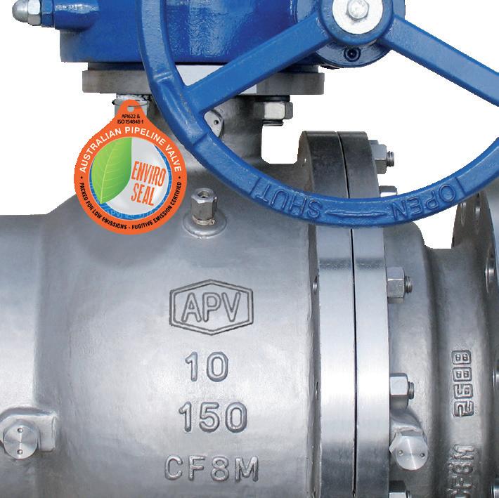
VALVE IDENTIFICATION
Each APV valve is identified with a nameplate. Below is an example. 2
1
2
3
5
6
7
8
9
When performing any work, ordering spare parts, or requesting technical support, please refer to this tag. The serial number, the part number and numbers cast on the side of the valve body are keys to proper valve identification.
1.0
STORAGE
1.1 TEMPORARY STORAGE
If valves are to be stored before installation, the following should be observed:
a) Keep the valves wrapped and protected as shipped from the manufacturer.
b) Do not remove the protective ends covering until the valve is ready for installation. This will reduce the possibility of foreign material damaging the internal valve components.
c) Valves stored outdoors should be positioned such that water does not accumulate in the valve body.
1.2 LONG TERM STORAGE
If valves are to be stored more than one year, they should be prepared in the following manner:
a) Remove the packing and apply a preservative to the packing chamber.
b) Do not remove the protective end covering.
c) Do not store the valves outdoors.
1.3 PREPARATION
a) Remove the valve end protection.
b) Prior to shipment from the manufacturer, a preservative may have been applied to the inner body of the valve. This preservative may have been removed with a solvent.
c) The inside of the valve should be inspected and blown out with compressed air. Adjacent piping must be clean and free from debris to prevent damage to the valve.
d) To prevent valve distortion, inefficient operation or early maintenance problems, support piping on each side of the valve.
e) Make sure the valve is positioned such that there is sufficient space so that the hand wheel is easily and safely reached and there is enough clearance for the stem when the valve is open.
f) Install the valve according to the flow indicator on the valve body where applicable.
2.0 OPERATION
The design of APV Standard Type plug valves is provide bubble tight shut off.
Plug valves have a quarter turn operation (i.e. They have a 90 degree rotation of the plug in operating from fully open to fully closed) and close in the clockwise direction when viewed from above the valve stem. It is possible to recognise when the valve is open or closed by the position of the grooves or raised pips in the top of the stem, these being in-line with the plug port. Multiport valve can have more than a quarter turn operation - these are also recognised by the grooves or raised pips in the top of the stem, being in-line with the plug port.
Plug valves can be used for throttling for limited periods as normally used for vent applications, bypass, blow down, kicker, equalisation, etc. If a plug valve is used for throttling for limited periods, then its suggested to proceed as follows:
1) Open the plug slowly to allow media to travel through the valve (this should occur when then opening angle is 20-30°)
2) Open the plug further to modulate the flow as required.
3) When throttling is no longer required continue to open until the valve is fully open. Leaving the valve in the partially open (throttled) position for long periods may cause damage and reduce the life of the seat.
Do not force valves that will not readily operate. Never stand downstream of a valve that is being opened to atmosphere. To prevent operation of valves that are installed where unauthorised personnel can interfere with them the valve should normally be locked with suitable locking device, have the wrench or handwheel removed or be chained through the handwheel.
DURING OPERATION TAKE INTO ACCOUNT THE FOLLOWING WARNINGS:
a- Graphite/Graphoil packing and body gasket is very brittle, any impacting, twisting or bending should be avoided.
b- The valve’s internal parts such as plug, stem, seating area, seals, gaskets shall be handled with care avoiding scratches or surface damage.
c- All tools and equipment for handling the internal parts shall be soft coated.
d- Valves can be fitted with gaskets or seals in PTFE, Buna, Viton, etc. Hence high temperatures will damage sealing components.
e- Never part open valve. Valve must be full open of full closed to avoid seat damage.
For all operations make reference to position number on part list of the applicable drawing listed.
2.1 MANUAL OPERATION
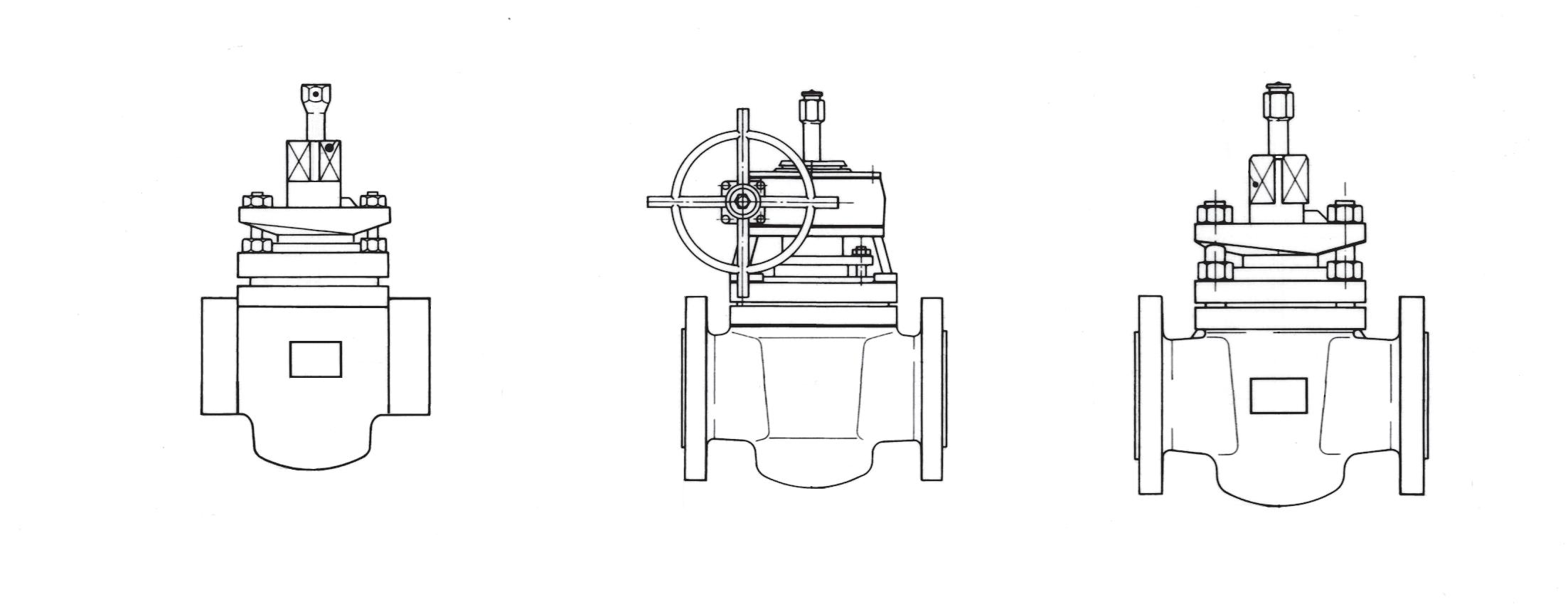
Valve adjustment is by clockwise turning of stem. Lever operated and gear operated valves have position indicator to indicate open or closed (see figure 1 & 2). Plug Valves must not be used for throttling. Valve must be full open or full closed.
2.2 WRENCH OPERATION
The wrench has a ‘square’ style head, and can be fitted to the valve in a number of positions to suit operation. The wrench must always be secured to the plug stem by tightening the retaining screw onto the plug stem. The are positive stops provided on the plug stem and gland to ensure correct operation of the valve.
During operation of the valve the use of excessive side loading on the wrench should be avoided. APV provide wrenches that are sized so that the force to operate the valve should be 15 NM maximum at the end of the wrench.
Figure 1
Figure 2
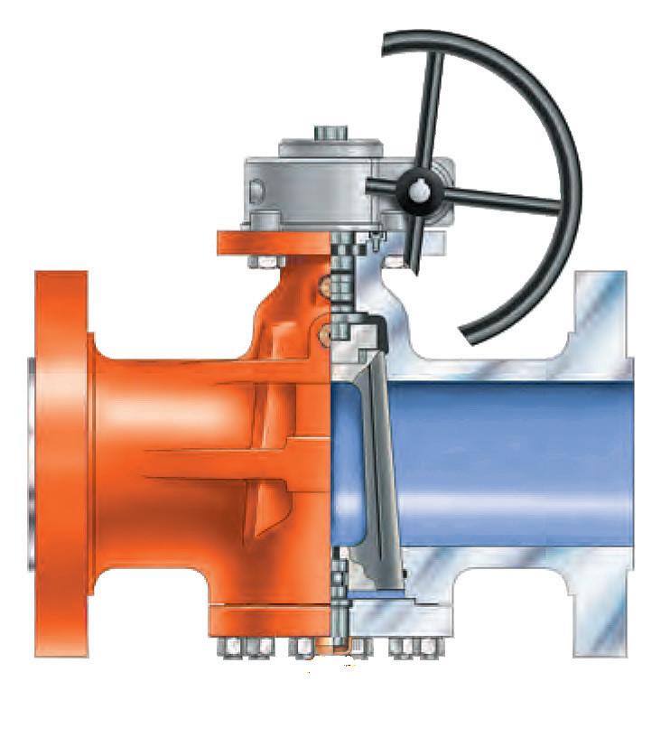
2.3 GEARBOX OPERATION
APV gearboxes have a visible arrow type position indicator on top of the gear housing. ‘OPEN’ and ‘SHUT’ positions are cast on top of the gear housing. The position indicator arrow points to these when in the fully opened and fully closed positions.
The gearbox handwheel can be secured to the gearbox input shaft by the pin, or by the key and the retaining screw. The close direction indicator must be visible on the end of the input shaft, and ensure that the retaining screw is tightened down. Gear unit stops should also be checked to ensure correct plug port alignment.
2.4 LOCK DEVICE
Where provided (optional) the valve has a locking lug that allows valve to be locked in full open or full closed position.
2.5 THROTTLING SERVICE
Valves used to regulate the rate of fluid flow may be subject to severe fluid turbulence. This turbulence can create a high-energy conversion within the valve and piping system. High noise levels indicate energy conversion either by the disturbance of liquids or by shock waves from gases. An example of low-level cavitation noise is the sound made by water in water pipes or a faucet. There is a possibility for mechanical damage to the valve and piping system when throttling of liquid flow results in severe and continuous cavitation conditions. Similarly, shock waves can result in damage to the system with gas flow under severe throttling conditions. APV personnel should be consulted on proper valve selection for throttling applications.
2.6 PRESSURE SURGE
Closure of a valve in a flowing fluid line will cause the flow rate of the fluid to be reduced to zero. If the fluid relatively incompressible liquid, the inertia of an upstream column produces a pressure surge at the valve, the magnitude of which is inversely proportional to the time required for closure. The surge pressure is also proportional to the length of the upstream fluid column and the fluid velocity prior to closure initiation. If the application involves a long upstream line, a long downstream line, high velocity, and/or rapid closure, separately or in any combination, the possibility of an unacceptable pressure surge should be investigated.
Also to be considered is condensation-induced pressure surges that occur when a fluid’s speed is changed by rapid condensation, or when a rush of water is accelerated by contact with stream. (For example, when condensation collects on one side of a closed valve that has steam on the other side, opening the valve will cause steam cavities to collapse, sharp pressure surges, and acceleration of condensation). Condensation-induced pressure waves can result in pressure pulses that are significantly higher than those produced by a sudden valve closure. In such events, non shock-rated grey iron valves installed in steel piping systems are particularly vulnerable to catastrophic failure. Traps are required to prevent the accumulation of condensation, and blow-off valves located at the low point in the system
are needed to ensure condensation drainage. Personnel involved in operation and/or maintenance must be familiar with the function of both these devices in relation to the shutoff valve operation and how to keep these valves in proper working order.
3.0 INSTALLATION
3.1 INSTALLATION INSTRUCTIONS
a) APV Standard Type plug valves are bidirectional, and can be installed vertical (stem operating end at the top), horizontal or any angle in between. Operating torque will increase considerably if the valve is installed in any other position, possibly resulting in seizure. The actuator may require support if it is not vertically above the valve. Ensure access to the sealant fitting, gland nuts and any drain plugs.
b) Flanged joints require compressive loading onto the gasket material where the normal line pressure forces are prone to separate the joint. There is to be no misalignment between the valve and mating faces.
c) Installation of flanged valves should follow prevailing site standards. When such standards do not exist the following should be used as a guideline.
d) Ensure the pipeline and flange faces are cleaned thoroughly and free of any debris which may be detrimental to flange sealing.
e) Ensure pipework has the correct gap to allow for the valve face to face length plus assembled gasket material width.
f) Locate the valve between the pipe ends and slide in the gaskets. If necessary, lever the mating flanges gently apart to allow for easy fitting of the gasket. Care should be taken to prevent damage to the sealing surfaces. Correct lifting equipment must be used when handling valves for operator safety.
g) Ensure bolts are of the correct size, length, and material for the service intended.
h) Screwed Ends - Pipe wrenches can be used to grip the valve body adjacent to the connection, while tightening it. Use of a thread sealant is recommended to ensure a pressure tight joint.
i) Assemble all bolts and loosely tighten. Diametrically and evenly tighten the bolts to the correct torque required for the specific gasket material, as per the gasket manufacturer’s recommendations.
j) It is recommended that the valves are left in the open position during fitting.
3.2 INSTALLATION POSITIONS
Plug valves are usually bidirectional, and therefore may be installed in either direction. In some cases, plug valves may be unidirectional, in which case the direction of flow will be indicated on the valve body.
Piping should be properly aligned and supported to reduce mechanical loading on the end connections.
3.3 PREPARATION FOR INSTALLATION
Before installation ensure all protective packaging is removed.
To ensure tight shut off it is recommended that additional sealant be injected prior to operation and re-test. Any excess sealant found around the plug port should be removed using a scraper. End connections should be cleaned to remove any unwanted paint or rust inhibitor. Significant problems can become apparent with any valve installed in an unclean pipeline. Ensure that the pipeline has been flushed free of dirt and debris before installation. The working environment should also be clean and clear of any debris which could contaminate the valve. During cleaning ensure the valve is in the fully opened or fully closed position. Water and inert gas such as carbon dioxide and nitrogen are unlikely to affect the sealant. It is recommended that valves be re injected with sealant after completion of cleaning when the use of solvents or steam cleaning are involved.
• Remove protective end caps or plugs and inspect valve ends for damage to threads, socket weld bores or flange faces.
• Thoroughly clean adjacent piping system to remove any foreign material that could cause damage to seating surfaces during valve operation.
• Verify that the space available for installation is adequate to allow the valve to be installed and to be operated.
3.4 END CONNECTIONS
3.4.1 Threaded
Ends
Check condition of threads on mating pipe. Apply joint compound to the male end of joint only. This will prevent compound from entering the valve flow path.
3.4.2
Flanged Ends
Check to see that mating flanges are dimensionally compatible with the flanges on the valve body ensure sealing surfaces are free of debris. Install the correct studs and nuts for the application and place the gasket between the flange facings.
Stud nuts should be tightened in an opposing crisscross pattern in equal increments to ensure even gasket compression.
3.4.3 Socket weld Ends
Remove all debris, grease, oil, paint, etc., from the pipe that is to be welded into the valve and from the valve end connections.
Insert the pipe into the valve end connection until it bottoms out in the socket weld bore. Withdraw the pipe 1/16” so that a gap remains between the pipe and the bottom of the socket weld bore to prevent cracks (ASME B16.11). Tack the pipe into the valve and complete the fillet weld.
Welded end plug valves in smaller diameters should be lightly closed to prevent damage to the seating surfaces and stem caused by thermal expansion during the weld process.
3.4.4 Buttweld End Valves
Clean the weld ends as necessary and weld into the line using an approved weld procedure. Make sure the pipe and body material given on the nameplate or body is compatible with the welding procedure. (Refer our compatibility cross reference chart for equivalent pipe, valve & fittings grades).
3.4.5 Valve Installation by Welding
After welding completion, open the valve and flush line to clean out any foreign matter.
The responsibility for welding of the valves into piping systems is that of those performing the welding. Refer to ASME B31.1, B31.3 etc. Written welding procedures covering all attributes of the process and materials to be welded shall be in accordance with Section IX of the ASME Boiler and Pressure Vessel Code and any additional requirements from the applicable piping code including any possible necessary localised post weld heat treatment depending on material specifications.
Packing leakage could result in personal injury. Valve packing is tightened prior to shipping but may require readjustments to meet specific service conditions. Do not attempt to change packing or stem seals whilst the valve is in line under pressure.
Personal injury may result from sudden release of any process pressure. APV recommends the use of protective clothing, gloves and eye wear when performing any installation or maintenance.
Isolate the valve from the system and relieve pressure prior to performing maintenance.
Disconnect any operating line providing air pressure, control signals or electrical power to actuators.
Check the packing box for pressurised process fluids even after the valve has been removed from the pipeline, particularly when removing packing hardware or packing rings.
If a gasket seal is disturbed while removing or adjusting gasketed parts, APV recommends installing a new gasket while reassembling. A proper seal is required to ensure optimum operation.
3.4.6 COMMISSIONING TESTS
All valves are factory tested in accordance with valve industry standards API 6D, API 598, BS EN 12266-1 or BS.5158, unless otherwise specified. It is recommended that you contact APV if there is an operational need to test the valve at a higher pressure, temperature or duration.
If water is used for testing, it is beneficial to dry out the valve internals by flushing the system with air or dry nitrogen, after the testing is completed.
4.0 MAINTENANCE
The main maintenance of a plug valve involves stroking, regreasing, packing adjustment and plug adjustment. Greasing is the most important activity as plug valves rely on grease to effect a seal on the seat. In summary the main maintenance activities are: -
4.1 VALVE SEAT LEAKAGE/PLUG ADJUSTMENT
APV standard type valves while in-line and on service should be regularly greased and very occasionally the gland packing buts should be tightened. Except in cases where the plug becomes heavily eroded or corroded valves can be fully maintained for years of trouble free service.
One of the most common problems associated with seat leakage is the lack of sufficient sealant to adequately fill and pressurise the sealant system. Introduce the correct amount of sealant into the valve and again check for seat leakage.
If a non-compressible fluid is trapped in the centre cavity of the plug, when the valve is in the closed position, injecting sealant at high pressures or high volumes can cause the plug to lock in place. This can also cause the cover bolts to yield, resulting in bonnet leakage.
4.2 VALVE LUBRICATION OVERVIEW
The valve must be fully OPEN or fully CLOSED otherwise all four grooves on the supply channels will not be connected. Only an expert trained plug valve maintenance specialist should undergo maintenance. Sealant can be injected whist the valve is in-line and under full working pressure. The following is only an indicative summary of procedures. See Appendix H for sample of sealants/ lubricants available. APV lubricated plug valves are designed to be lubricated using two different methods
- Via built-in lubricant screw using grease sticks.
- With hydraulic lever gun.
Insert the correct size and type of sealant stick into the threaded hole, and screw in the injector. Depending on how much sealant is in the valve will determine how many sealant sticks may need to be injected. Initially the sealant injector should turn on easily, while the sealant chambers are filling up. Once these are filled, it will become more difficult to turn, but keep turning the injector to inject more sealant. After it has become difficult to inject sealant, it will suddenly become easier as the plug is lifted off the seats - at this point inject another half a stick and then wait about 5 minutes for the sealant to flow around the seats. Inject more sealant until it is flowing easily and the valve is operating easily.
Take care when removing the injector, in case there has been any leakage of the service medium through the double check valve.
Method 1 via built in lubricant screw (where applicable)
1. Remove lubricant screw and introduce grease stick into the stem reservoir. The check valve in the reservoir eliminates the danger of any loss of grease during loading.
2. Replace the lubricant screw and tighten down to pressurise the grease which is forced past the check valve into the upper chamber and then into the lower chamber via the groove machined into the plug. The grooves are positioned so that they are never exposed and cannot be entrained by the process fluid.
3. Rotate the plug to evenly distribute lubricant.
4. If necessary repeat procedure until lubricant is visible inside valve cavity.
Method 2 with hydraulic lever gun
1. Charge the lever gun following manufacturers instructions.
2. Connect coupler of the lever gun to the universal button head of the lubricant screw.
3. Inject the grease by means of hand lever pumping.
4. Turn the plug for even distribution of lubricant.
5. Continue lubrication until lubricant is visible inside the valve body.
Monitor the pressure gauge during the sealant injection process. For sealant to flow onto the valve seats, enough sealant at sufficient pressure has first to be injected to over come the line pressure, to fill
any cavities in the sealant chamber and grooves, and to overcome the flow resistance through the valve sealant system.
It is desirable but not essential; to operate the valve either partially or fully after injecting sealant, to help spread the sealant over the entire seating surfaces.
4.2.2 Valve sealants and lubricants
Only sealants recommended for TAPER plug valves should be used.
Do not use the following types of sealant:
a) Sealant supplied by cylindrical/parallel plug valve manufacturers. These are much higher viscosity than taper plug valves require and will substantially increase the valve torque.
b) Commercially available lubricating grease such as bearing grease. These greases do not have the chemical resistance, lubricating and sealing properties required by taper plug valves.
Do not use plug sealant grease for the stem packing where the design requires PTFE plastic packing (see below explanation). Where an allen key closure system is fitted on the stem sealant nipple, packing ‘sticks’ can be used as stated below. Mushroom head grease nipple may also be fitted.
For leaking valves it is common for operators to use a higher viscosity ‘sealant’ in the sealing grease channel in lieu of conventional sealant/lubrication. Some types are even laced with Teflon to help seal even very worn valves. However, special heavy sealants can eventually harden dramatically increasing torques and blocking grease supply channels preventing the replenishment of replacement lubricant reaching the critical seating areas. In addition, they can dramatically increase torque. This can happen due to higher temperatures, lack of maintenance, time, or just due to the nature of the media being handled. Some sealants can also block secondary check valves inside lubricant fittings. Flushing agents are available to attempt to clear hardened grease without having to remove the valve from the line. Lighter sealants (lubricants) are available which enjoy a longer life and tend to harden slower. However, on the down side these lighter sealants flush away quicker and provide a less effective seal on worn or corroded valves.
It is important to remember that in small sizes below 50 NB depending on class (typically those without a flanged top bolt gland) the stem packing is the primary seal and only stem packing compound should be used to top up the packing, not grease sealant. Grease sealant is only used for the plug/seat area. In smaller size and lower pressure plug valves, ‘packing sticks’ are used and can be screwed in through the top of the stem with a bolt in lieu of using a grease fitting. If there is no body grease fitting, then the sealant channel on top of the stem supplies sealant to the plug and the seat. Bolted style gland packed valves do usually (optionally in smaller sizes) have a separate stem sealant injector but this is only needed in an emergency to temporarily seal a damaged stem seal (refer to Appendix B and C).
The purpose of lubrication is for 3 reasons:-
- To protect the surface seal of the valve from corrosion and abrasion.
- To contribute to a good seal.
- To contribute to an easy action.
The frequency of re-lubrication depends upon the operating conditions from the required mode of sealing. Generally the valve should be regreased every 3 or 4 operations of the valve especially if used high pressure gas however it depends entirely on the period between each operation of the valve.
The following tables gives you the minimum frequency of re-lubrication according to the temperature range and service type. ANSI class 600 and above should be greased more frequency especially if the media is high pressure gas. Special grease should be used for low and high temperature.
The quantity of grease for re-lubrication also depends on the operating conditions, however the usual amount is about 2 gr/mm of passage.
TABLE 1
Frequency of lubrication using temperature as a guide
TABLE 2
Frequency of lubrication using service as a guide
Infrequent operation, valve either fully opened or fully closed. Non abrasive gases or liquids.
Infrequent operation, valve either fully opened or fully closed. Abrasive gases or liquids.
Throttling services and abrasive slurries.
Every 20 operations, minimum twice per year. But, depends on media, temperature, etc.
Every 10 operations, minimum 4 times a year. But, depends on media, temperature, etc.
Every 5 operations, minimum 8 times a year. But, depends on media, temperature, etc.
TABLE 3
Frequency of lubrication using operation frequency as a guide
The choice of lubricant should be in accordance with the process medium and the service temperature range (see lubrication Table 2 & 3 above).
It is recommended that the valve be periodically stroked (at least partially) to ensure valve functions, and will aid to prevent seizure/galvanisation on any mating surfaces (or in the case of resilient seats). Duration depends on service, criticality, etc.
There are different types of lubricants available depending on temperature and service. Special lubricants for worn or corroded valves are available as well as flushing agents to remove old grease.
Use extreme caution when injecting sealant into a valve in the closed position with a non compacting fluid in the valve.
B) CONFIRM SUSPECTED STEM LEAKAGE
The following methods can indicate stem leakage.
a) Gas services - applying a detergent solution around the stem area will produce soap bubbles if the stem is leaking. A bad leak may be heard as a hissing noise from the stem area.
b) Liquid services - stem leak on a liquid service will be visible as liquid flowing out from where the stem protrudes from the body.
c) Gear operated valves - the area where the stem protrudes from the body is hidden by the gear operator. Confirm stem leak by observing or applying a detergent solution around relief valve (where fitted) in the gear operator indicator plate, and the gear operator to the valve body mounting area.
d) Portable electronic hydrocarbon detectors - some are sensitive enough to detect stem leaks by placing the probe adjacent to the stem.
If a hexagon socket/headed screw bottoms out inside the stem packing, and the stem is still leaking, then more stem packing compound needs to be loaded into the stem packing. This is done by removing the hex socket/headed screw and putting a new piece of stem packing compound into the injector unit and energising it with the hexagon socket/headed screw.
4.2.3 Adjustment of gland
The gland has two functions, to effect a seal on the stem and also to give a plug loading into the body. The gland should always be reasonably tight to give correct resistance for the sealant system - if the gland is loose then the sealant film will not properly form between the seats. Over a period of timeparticularly if the valve is subject to elevated or cyclic temperature fluctuations - the gland will need to be tightened.
Using a wrench, tighten with reasonable hand force. Take care not to over tighten or the plug will not turn. Once the gland has been tightened, sealant should always be injected and the valve operated to check that the valve is working correctly.
5.0 REPAIR
Only minor repair should be attempted. Major repairs should be undergone by an APV approved plug valve specialist repairer. This is a general guide.
5.1 DISASSEMBLY
During disassembly care must be taken to avoid damage to individual component surfaces. Similar care should be taken with gasket contact areas of flanges. For drawing refer to our as-built drawing for each item supplied with order. The below procedure is a general guide, parts vary according to size & class. Disassembly should be performed by an APV approved service centre. Refer Appendix A, B & C as a guide but consult the as-built drawing as designs vary according to size, class & style.
1. Remove the valve from pipeline with plug in the OPEN position. Before removing valve bleed off residual pressure that may be in the body cavity.
2. Remove valve operator (gearbox or wrench).
5.2 INSPECTION & REPAIR
1. Degrease and clean all components of the valve. Particular attention should be paid to the cleanliness of the sealant grooves in the plug.
2. Clean and degrease the upper and lower chambers in the body and visually check for signs of damage or wear.
3. Visually examine the plug surfaces and the contacting surfaces of the valve body for damage or wear.
4. There should be no deformation or wear on cover.
5. Replace any worn or damaged parts such as: O-rings, thrust bearing, diaphragm, etc. TABLE 4
6.0 GEARBOX RE-LUBRICATION
The gear unit is factory pre-lubricated and does not require lubrication. Where grease nipples are fitted (much larger sizes) then they can be lubricated through the grease nipples once every 24 months. However, most types of gear operator do not need any lubrication for their entire life. The gear teeth racks on worms and wheels do not normally require re lubrication. However, if operation becomes difficult of noisy, this indicates a lack of lubrication. In this case, re-lubrication is recommended.
The procedure is as follows:
1. Remove the gear cover to access gearbox internals.
2. The lubricant is applied to all tooth racks in a layer of about 1 mm.
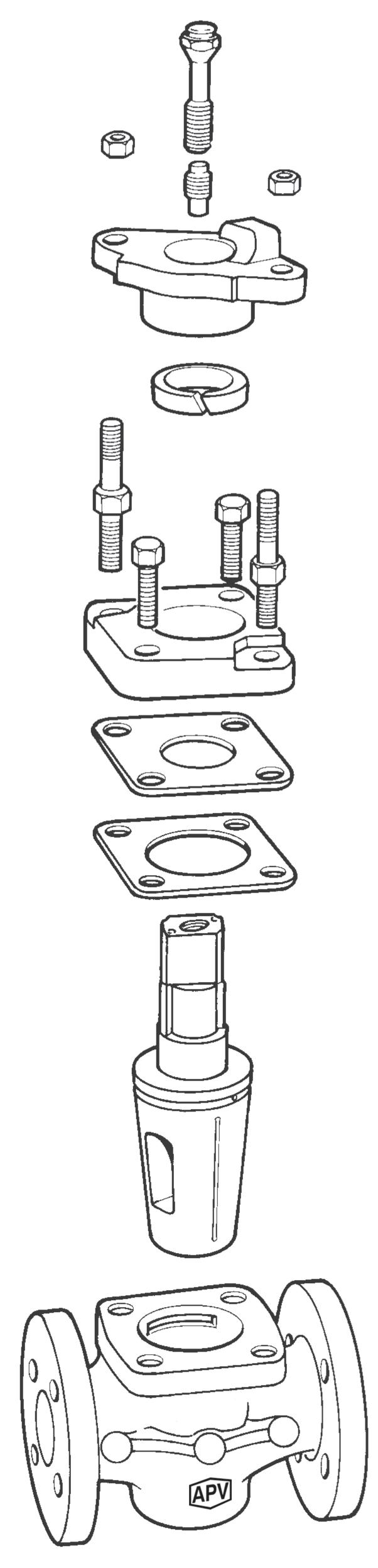
APPENDIX A
Range & Types
Lubricant fitting (Combination plunger)
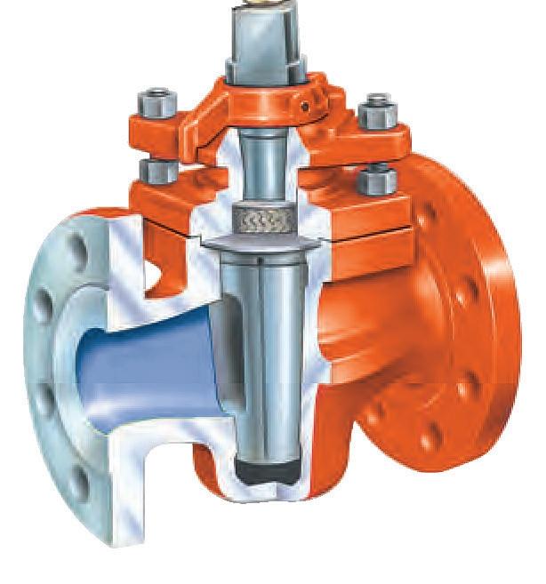
Gland stud
Gland
Stud
Sealant channels
Wrench
Check valve
Gland packing Shim packing ring
Bonnet
APPENDIX B
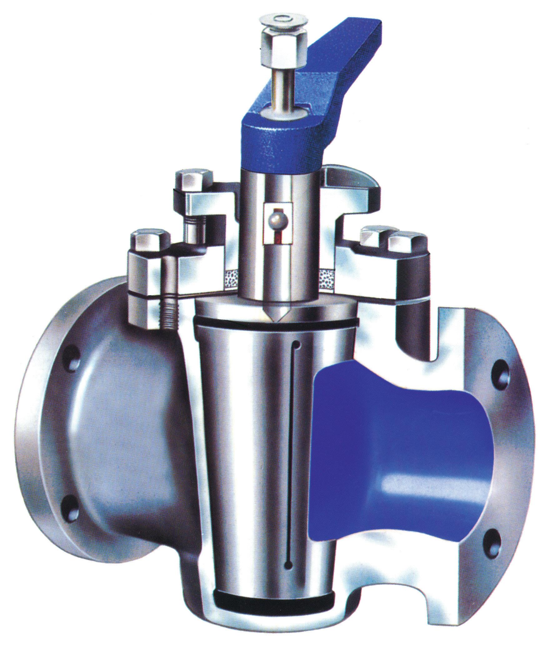
Sample Drawing
Type, Lubricated Plug Valve, Short Pattern, Taper Plug (Aud Style) Model SAPM-SSW23CIB, NPS 2~4” (DN50~DN100) Class 150 RF Lever Operated
APPENDIX C
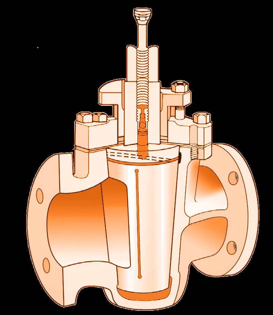
Standard Design*
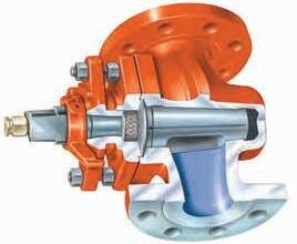
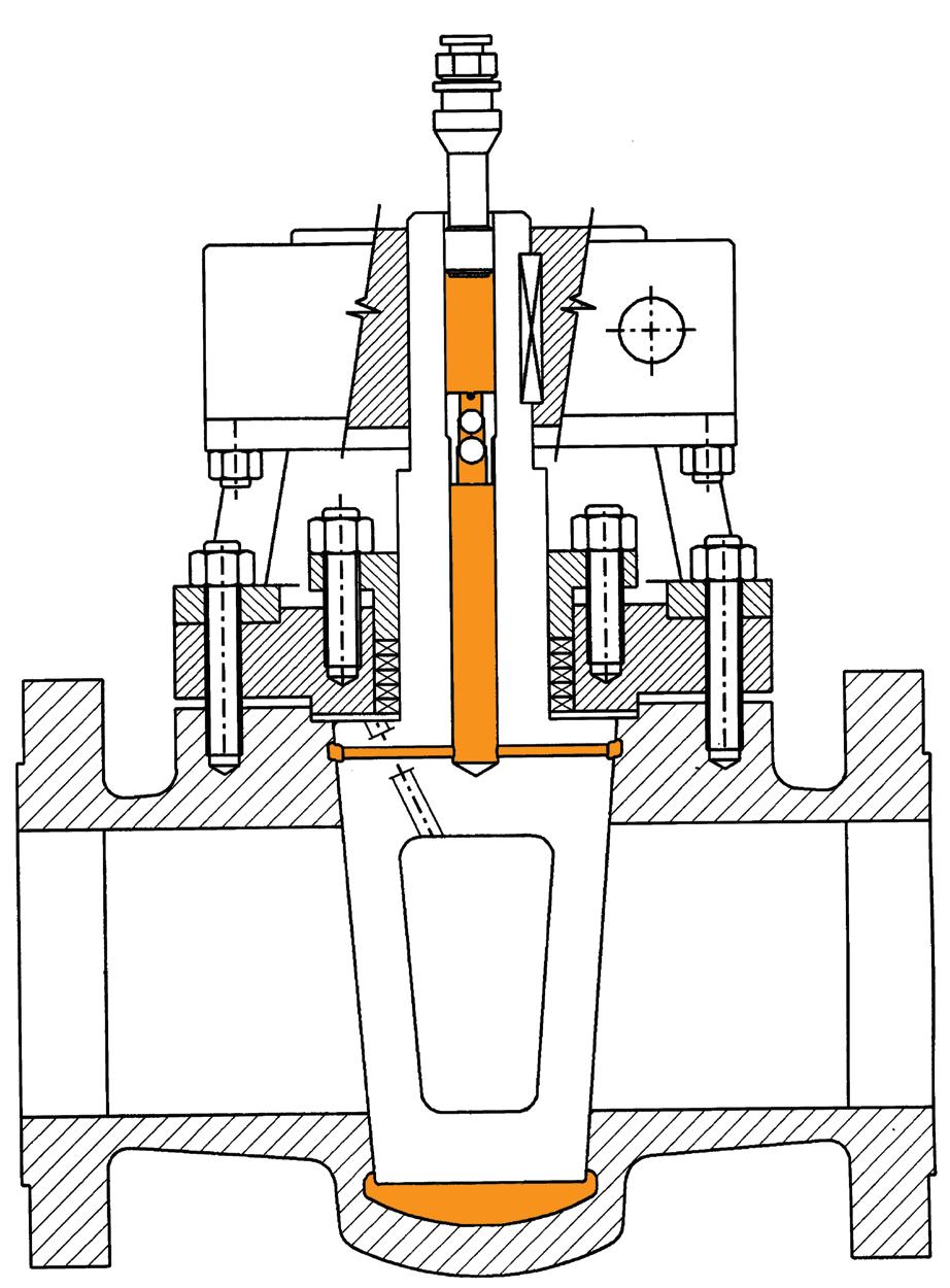
The standard style plug valve has the stem extended from the top of the valve. The valves have a bolted cover which retains the plug in case the gland is removed. The gland maintains the pressure in the cover and prevents any leakage through the stem as well as retaining the plug in position. The gland supports the packing and acts as an anti-friction bearing to prevent stem packing rotation. Plug lubrication grease is injected through a nipple (fitted with a check valve). Greasing can be done when the valve is under pressure. The plug grooves avoid grease leakage into the line as during rotation each groove is isolated from the other grooves.
2
3**
4
5
* Indicative sample SAPM B.O.M. only, refer to as-built drawing.
APPENDIX D
Typical
Main Material Types
Reference only, design varies according to size, class & customer preference. Refer to as-built drawing
APPENDIX E
Dimensions regular pattern plug valves standard type ANSI 150 SCREWED OR SOCKET ENDS WRENCH OPERATED
(1) Torques shown are for A193 B7/B7M/B8/B8M and A320 L7/L7M/B8/B8M.
(2) Torque tolerance ±10%.
(3) For temperatures above 750°F (400°C) use 75% of the torque values.
(4) Above torque values are with the bolts lubricated.
(5) Values above are based on 30,000 psi (206.85 Mpa) bolting stress and lubricated with heavy graphite and oil mixture or a copper based anti-seize grease.
(6) Do not exceed by more than 25% of values stated when emergency torquing is required.
(7) All bolts shall be torqued in the pattern as shown in Appendix E over page to ensure uniform gasket loading.
(8) Optimum torque can vary depending on type of body gasket but do not increase torque more than 10% above those shown.
(9) Consult us for other bolt material.
(10) Most B8M and B8 bolts are class 1 so do not assume class 2 unless you are sure.
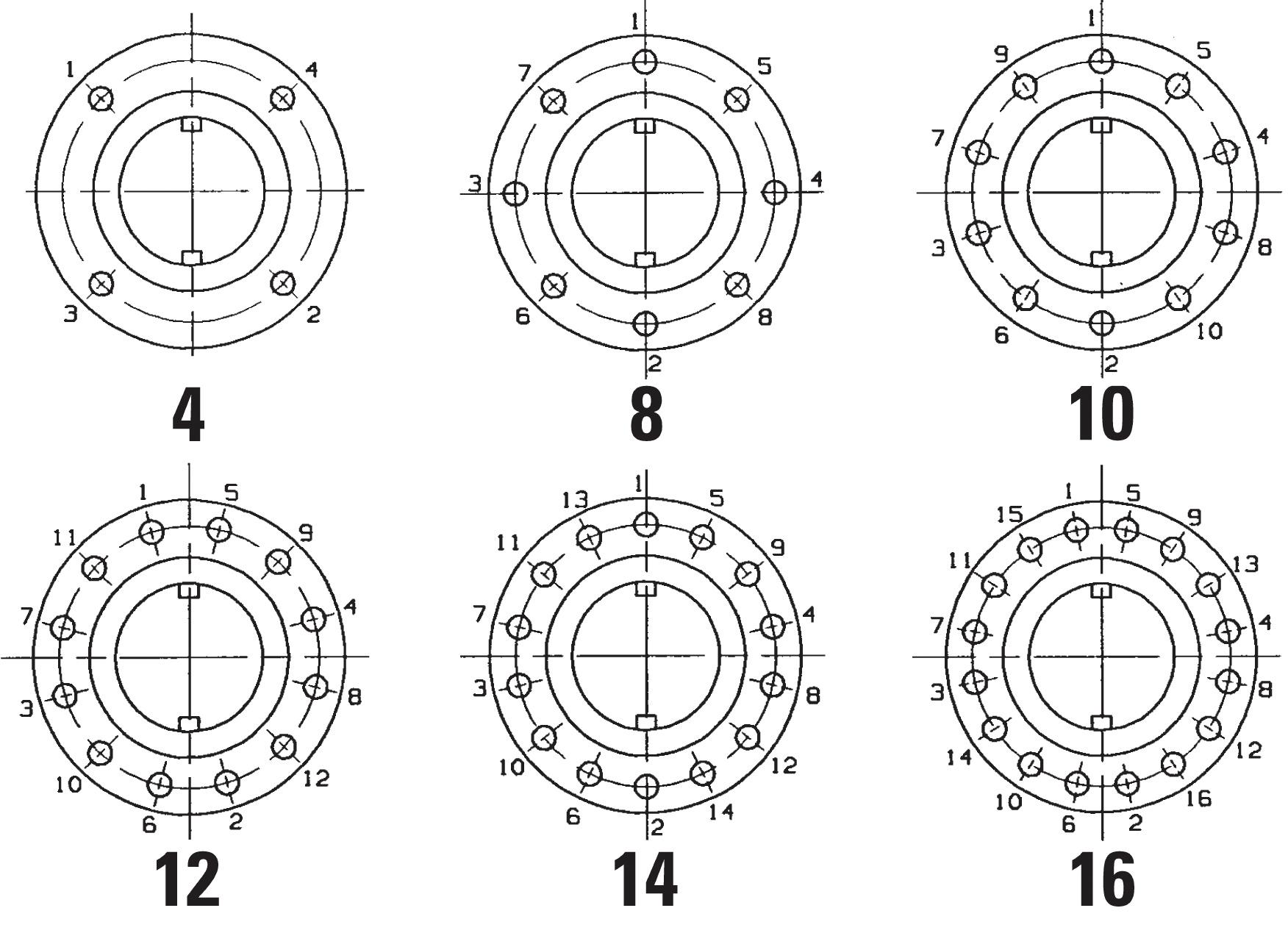
Bolt tensions shown must be decreased by 25% when other or no lubrication used. Non lubricated bolts can have an efficiency of less than 50% the torque of values stated. Indicative torques are shown only, different body gasket systems, different seating styles, different sizes & classes, etc., will have different torque requirements. Furthermore, other stud grades can have much lower torque capabilities depending if class 1 or class 2 and or above variables.
APPENDIX G
Bolt Tightening Sequence
Torque chart
Torque is at maximum Delta P. Numerous factors can dramatically increase torque such as: - temperature, hardness of the grease over time, particulates in media, media type, grease type, etc.
Aliphatic hydrocarbon liquid and gas service. Ideal for pipeline and compressor station operation. Excellent for use in heavy H2S, saline or salt water service. Jet-Lube Ezy-Turn #3 Arctic
LUBRICANT FUNCTION:
1. To minimise friction during operation of valve.
2. To protect seat surfaces from corrosion.
3. To prevent leakage by lubricant encircled with lubricant grooves.
Climax and Ezy-Turn model numbers shown are only provided as an example. Please consult your nearest manufacturer for their equivalent.
WARRANTY
1. LIMITED WARRANTY: Subject to the limitations expressed herein, Seller warrants that products manufactured by Seller shall be free from defects in design, material and workmanship under normal use for a period of one (1) year from installation but in no case shall the warranty period extend longer than eighteen months from the date of sale. This warranty is void for any damage caused by misuse, abuse, neglect, acts of God, or improper installation. For the purpose of this section, “Normal Use” means in strict accordance with the installation, operation and maintenance manual. The warranty for all other products is provided by the original equipment manufacturer.
2. REMEDIES: Seller shall repair or replace, at its option, any non-conforming or otherwise defective product, upon receipt of notice from Buyer during the Manufacturer’s warranty period at no additional charge. SELLER HEREBY DISCLAIMS ALL OTHER EXPRESSED OR IMPLIED WARRANTIES, INCLUDING, WITHOUT LIMITATION, ALL IMPLIED WARRANTIES OF MERCHANTABILITY AND FITNESS OR FITNESS FOR A PARTICULAR PURPOSE.
3. LIMITATION OF LIABILITY: UNDER NO CIRCUMSTANCES SHALL EITHER PARTY BE LIABLE TO THE OTHER FOR INCIDENTAL, PUNITIVE, SPECIAL OR CONSEQUENTIAL DAMAGES OF ANY KIND. BUYER HEREBY ACKNOWLEDGES AND AGREES THAT UNDER NO CIRCUMSTANCES, AND IN NO EVENT, SHALL SELLER’S LIABILITY, IF ANY, EXCEED THE NET SALES PRICE OF THE DEFECTIVE PRODUCT(S) PURCHASED DURING THE PREVIOUS CONTRACT YEAR.
4. LABOUR ALLOWANCE: Seller makes NO ADDITIONAL ALLOWANCE FOR THE LABOUR OR EXPENSE OF REPAIRING OR REPLACING DEFECTIVE PRODUCTS OR WORKMANSHIP OR DAMAGE RESULTING FROM THE SAME.
5. RECOMMENDATIONS BY SELLER: Seller may assist Buyer in selection decisions by providing information regarding products that it manufacturers and those manufactured by others. However, Buyer acknowledges that Buyer ultimately chooses the product’s suitability for its particular use, as normally signified by the signature of Buyer’s technical representative. Any recommendations made by Seller concerning the use, design, application or operation of the products shall not be construed as representations or warranties, expressed or implied. Failure by Seller to make recommendations or give advice to Buyer shall not impose any liability upon Seller.
6. EXCUSED PERFORMANCE: Seller will make a good faith effort to complete delivery of the products as indicated by Seller in writing, but Seller assumes no responsibility or liability and will accept no back-charge for loss or damage due to delay or inability to deliver, caused by acts of God, war, labour difficulties, accidents, inability to obtain materials, delays of carriers, contractors or suppliers or any other causes of any kind whatever beyond the control of Seller. Under no circumstances shall Seller be liable for any special, consequential, incidental, or indirect damages, losses, or expense (whether or not based on negligence) arising directly or indirectly from delays or failure to give notice of delay.