INTRODUCTION
The majority of this information is common knowledge to experienced steel valve users. When properly installed in applications for which they were designed, APV valves will give long trouble free service. This instruction is only a guide for installation, operation and minor maintenance. A professional APV approved valve engineering facility should be utilised for reconditioning and minor repairs.
Note
We do recommend that this entire document be read prior to proceeding with any installation or repair. Australian Pipeline Valve and it’s parent company take no responsibility for damage or injury to people, property or equipment. It is the sole responsibility of the user to ensure only specially trained valve repair experts perform repairs under the supervision of a qualified supervisor.
RESPONSIBILITY FOR VALVE APPLICATION
The User is responsible for ordering the correct valves. APV Valves are to be installed in the observance of the pressure rating and design temperature. Prior to installation, the valves and nameplates should be checked for proper identification to be sure the valve is of the proper type, material and is of a suitable pressure class and temperature limit to satisfy the applications requirements.
Do not use any valve in applications where either the pressure or temperature is higher than the allowable working values. Also valves should not be used in service media if not compatible with the valve material of construction, as this will cause chemical attacks.
RECEIVING INSPECTION AND HANDLING
Valves should be inspected upon receipt to determine:
- Compliance to purchase order requirements.
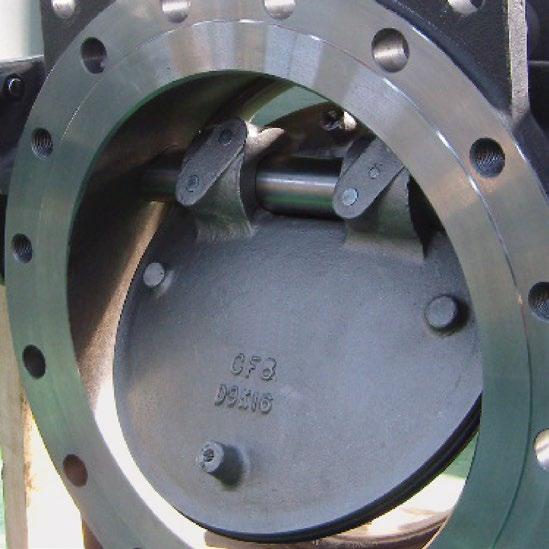
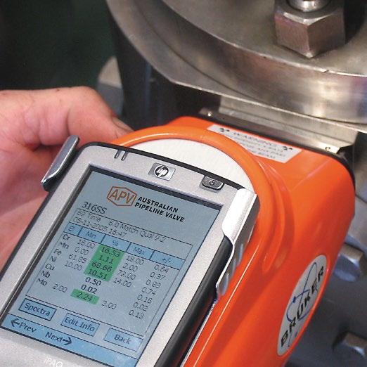
- Correct type, pressure class, size, body and trim materials and end connections (this information may be found on the nameplate or may be stamped on the body of the valve).
- Any damaged caused during shipping and handling to end connections, hand wheel or stem.
The End User is advised that misapplication of the valve may result in injuries or property damage. A selection consistent with the particular performance requirements is important for proper application and is the sole responsibility of the end user.
Australian Pipeline Valve - Installation, Operation and Maintenance Manual 2
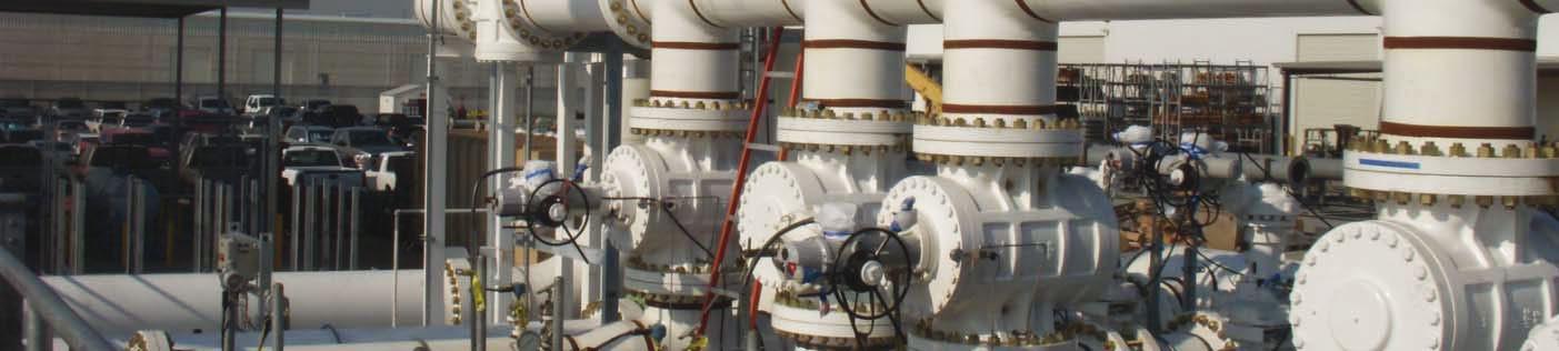
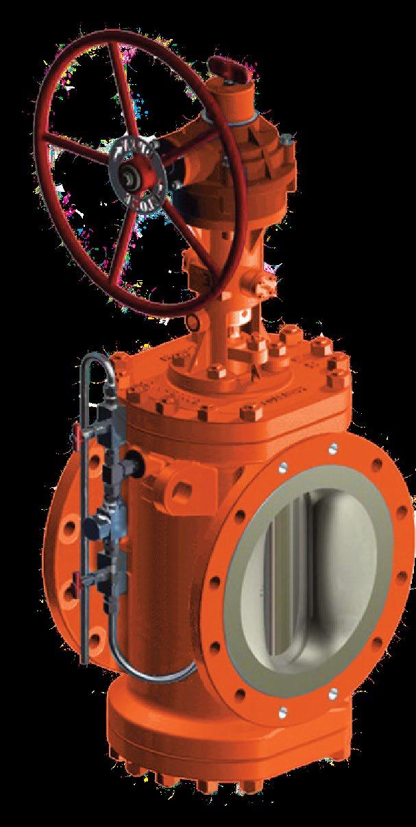
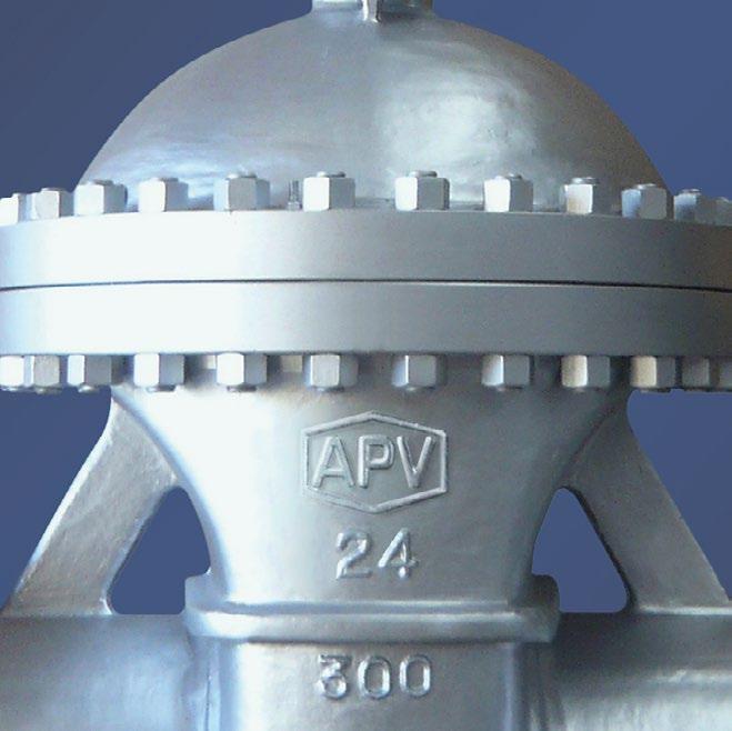
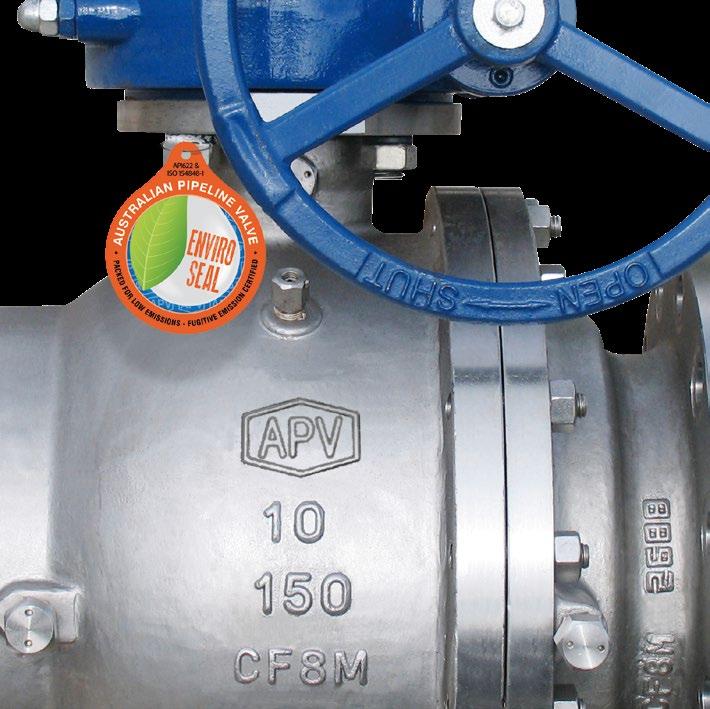
SEAL PLUG VALVE DOUBLE BLOCK & BLEED API6D - TWIN SERIES
EXPANDING
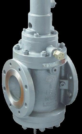
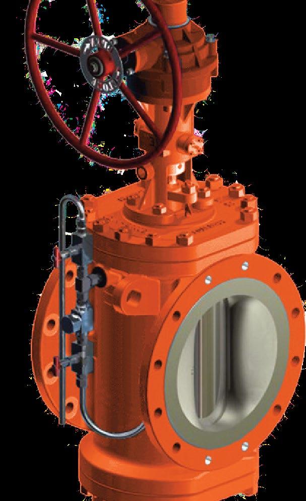
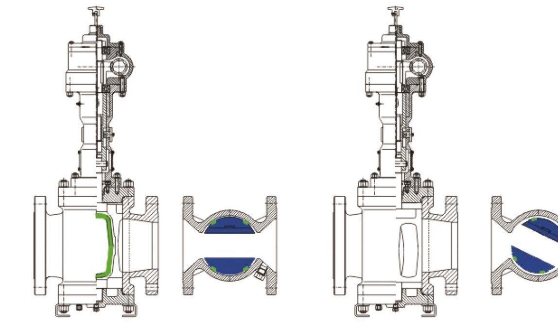
MODEL TWIN EXPANDING SEAL PLUG VALVE NON LUBRICATED DOUBLE BLOCK AND BLEED
DOUBLE BLOCK AND BLEED SOLUTIONS
• Permanent integral thermal relief and bleed function
• In-line mainternance in case of seal replacement
• Very short installation space required
• Double isolation function, according API-6D/ISO14313
• Only 1 actuator required to operate the valve
Unlike other valve types, the APV TWIN Twinseal style Dual Expanding Twinseal style plug valve creates an optimum seal without causing any abrasion and wear, providing a ‘zero-leakage’ solution, upstream and downstream ensuring a long life-time of the seals and valve, as well as a low opening and closing torque. This unique design is combined with a bleed function, all in one valve, saving space as well as providing a reliable, safe and economical solution.
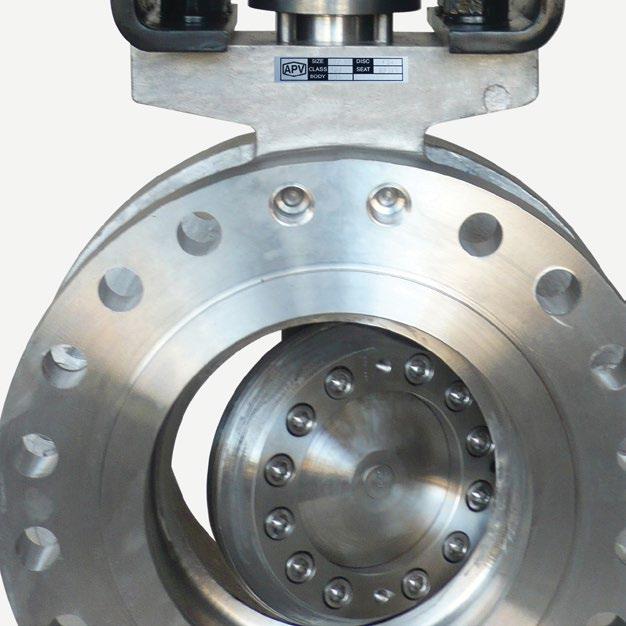
PRODUCT STRUCTURAL FEATURES
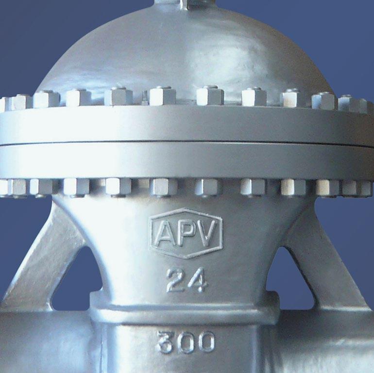
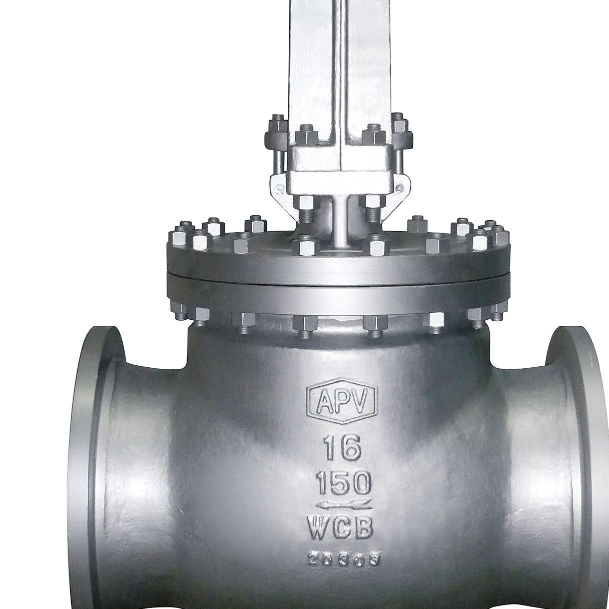
Used in various industries such as petroleum, chemical industry, chemical fertiliser, power industry etc. Class 150 - 1500LBS and working temperature of -29~180°C.
MAIN STRUCTURAL FEATURES
• The Twinseal style double expanding plug valve has a rugged structure, reliable sealing, excellent performance and exact tolerances.
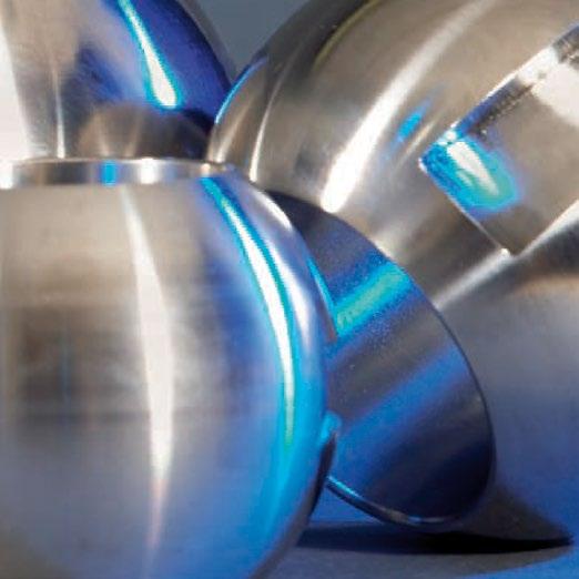
• Sealing rings around the valve plug provide the seal. It has a unique design incorporating machined and pressed sealing rings.
• Bi-directional, double block and bleed.
OPERATION PRINCIPLE
When the hand wheel is turned, the plug will rotate toward the closing direction for 90 degree turn closing, the plug will then be firmly seated after moving downward into its closing position.
When the hand wheel is turned inversely, first of all the plug will move upward and the valve plug and valve seat will be separated till the valve plug is turned 90 degree driven by the plug and finally the bore of the plug will be in alignment with the channel of valve body.
The advantage of this type of valve is during the opening and closing of the valve, the plug and valve seat are separated and there is no friction, thus the sealing face experiences no abrasion in the process, at the same time the soft seal is applied for sealing so that there will be no leakage in the process of closing.
Australian Pipeline Valve - Installation, Operation and Maintenance Manual 3
EXPANDING SEAL PLUG VALVE DOUBLE BLOCK & BLEED API6D - TWIN SERIES
PERFORMANCE
* High/ low temperature available up to 2500 Class.
Non-slam
The operator is self locking so that line pressure cannot force the plug to rotate. This prevents slamming and risk of injury.
Tight shut off
When the valve is closed, the seating segments are wedged tightly between the plug and body metal to metal. The soft seat material is compressed into the recessed groove. The design does not require springs or pressure to effect a seal.
Double block and bleed and zero leakage
The Twinseal valve provides upstream and downstream seal in both directions and a bleed point is then provided between the two seats, to prove no leakage.
Zero-leakage
The Twinseal meets the demands of frequent cycling and verifiable, reliable zero leakage with positive shut-off upstream and downstream.
Zero wear
Twinseal valves provide positive shut-off with zero leakage.
The design of the valve ensures that during opening and closing the seals are not in contact with the body. Only at the last stage of closing does the seal contact the body - and then the force is compression only.
Every turn of the handwheel retracts the seals from the body.
That means no wear to the seals and long life.
Large port
Twinseal valves have a nominal plug port of 60 - 70% thus effecting minimum pressure drop. True circular full port also available.
Closing Operation
Australian Pipeline Valve - Installation, Operation and Maintenance Manual 4
SEAL PLUG VALVE DOUBLE BLOCK &
EXPANDING
BLEED API6D - TWIN SERIES
Class (MPa) Shell Test (MPa) Seating Test Suitable Suitable Operator Handwheel, bevel gear,electric-actuated Temp. Medium 150 3.0 2.2 180°C* Water oil and gas Design Standard API599, API6D, ISO 14313 300 7.5 5.5 Face to Face ASME B16.10 600 15.0 11.0 Flange End ASME B16.5 900 22.5 16.5 Test and Inspection API598, API6D
SPECIFICATION TECHNICAL SPECIFICATION
EXPANDING SEAL PLUG VALVE DOUBLE BLOCK & BLEED API6D - TWIN SERIES
MAIN PARTS MATERIALS
1
2
3 Bearing Assembly
4 Drain Valve Assembly
5 O-Rings NBR, PTFE, VITON
5A Gasket SW316 + Graphite
6 Gasket Spiral Wound
7 Bolt ASTM A193 - B7, A320 - B8, A193 - B8M
8 Nut ASTM A194 - 2H, A194 - 9, A194 - 8M
9
14
15
18
19
Stem ASTM A182 - Gr. F6a, ASTM A182 - 316
20 Handwheel ASTM A436 Gr. 60 - 40 - 18, A216 - WCB
21 Yoke Nut ZQA 19 - 4
22 Guiding Stud ASTM A182 - Gr. F6a, ASTM A182 - F22, ASTM A351 - CF8, CF8M, CF3, CF3M
23 Pin ASTM A182 - Gr. F6a, ASTM A182 - F22, ASTM B637-718 Inconel, ASTM A351 - CF8, CF8M, CF3, CF3M
24 Sealant Nipple Assembly
BLOCK & BLEED:
DBB - Double Block and Bleed , method to test seat integrity with valve closed while under pressure.
DIB - Double Isolation and Bleed, Bi-Directional seating. API6D definition of redundant sealing surfaces in both flow directions.
Australian Pipeline Valve - Installation, Operation and Maintenance Manual 5
Part Name Material
No.
Body ASTM A216 - WCB, ASTM A351 - CF8, CF8M, CF3, CF3
Lower Bonnet
ASTM A216 - WCB, ASTM A105, ASTM A351 - CF8, CF8M, CF3, CF3M
Disc ASTM
CF8, CF8M,
CF3M 11 Bonnet ASTM
Bearing Assembly
Slip Sealing Ring Viton,
Plug ASTM A216 WCC+ENP, ASTM A182 - Gr. F6a, ASTM A182 - F22, ASTM A351 - CF8, CF8M, CF3, CF3M 10
A182 - Gr. F6a, ASTM A182 - F22, ASTM A351 -
CF3,
A216 - WCB, ASTM A351 - CF8, CF8M, CF3, CF3M 12
13
PTFE
O-Rings
NBR, PTFE, VITON
Packing
Gland ASTM
Yoke ASTM
Flexible graphite + stainless steel, PTFE 16
A216 - WCB, ASTM A351 - CF8, CF8M, CF3, CF3M 17
A216 - WCB, ASTM A351 - CF8, CF8M, CF3, CF3M
Slide Bushing
ASTM A216 - WCB, ASTM A105, ASTM A351 - CF8, CF8M, CF3, CF3M
Stem/Back
Side view End view
PRESERVATION & STORAGE
1.1 STORAGE
a- If storage in the field for a long time before installation is necessary, it is suggested to put valves in a dry and/or covered place. In this case the packaging and end covers integrity is especially important.
b- All the valves are supplied with special plastic ends to cover and protect the internal parts. We recommend you do not remove them during storage period.
c- Valves should be left in the open position (unless actuated and set fail closed).
1.2 PERIODIC MAINTENANCE DURING STORAGE
In case of extended storage, the valves must be inspected and maintained as follows:-
• External surfaces must be inspected to ensure no damage to flange faces, paint finish etc. In case of the presence of rust and/or damaged painting, the area must be cleaned by brushing, degreasing & repainting.
• The protection must be restored following the instruction indicated from APV in accordance with the painting cycle used.
• Without any ball movement, the internal surface of the valves must be inspected to check the complete absence of dust, rust, foreign matters and the integrity of lubricant coat. If not satisfactory then clean and lubricate the internal part using a nebulised lubricant. Do not leave any lubricant on the seat itself or else the seat may attract debris which in turn could damage the seat.
• After cleaning and lubrication the ball must be operated (close/open complete stroke).
• The ball must be kept in the full open position during installation.
• The end of the valve must be protected using the same end covers.
• We recommend you tropicalise bore and ends of valves if stored in humid or salt air environment. Grease bore with valve full open so no grease is applied to soft seat inserts.
1.3 ENVIRONMENTAL CONSIDERATIONS
According to ISO 14000 regulations and the environmental policy of APV the recyclability of the components that form part of APV valves is as follows:
Recyclable components:
Metal parts, PTFE (hard), plastic plug (low-density polyethylene).
Non-recyclable components:
PTFE mixed with other compounds (glass-fiber, graphite, etc.), nylon, graphite and graphite mixed with metal.
Australian Pipeline Valve - Installation, Operation and Maintenance Manual 8 EXPANDING SEAL PLUG VALVE DOUBLE BLOCK & BLEED API6D - TWIN SERIES
2.0 INSTALLATION
Orientation
APV DB&B expanding plug valve may be installed in any position.
Flow direction
The APV plug valve design is bi-directional. Flow shut-off is achieved equally on both sides of the plug in-dependent of flow direction.
Note: The use of a Differential Thermal Relief (DTR) does result in a preferred flow direction.
2.1 VALVE PREPARATION
a- Remove the ends protectors and check accurately the status of the valve as indicated in point 1.2.
b- Prior to shipment, a preservative/corrosion inhibitor may have been applied to the inner body of the valve. This preservative/corrosion inhibitor can be removed with a solvent, provided the solvent used does not affect the seats/seals used in the valve.
c- Do not operate the valve until the following procedures have been fully applied:
• Clean internal conduits.
• After cleaning the ball must be operated (one complete stroke).
• During installation the ball must be kept in the fully open position.
2.2 VALVE INSTALLATION
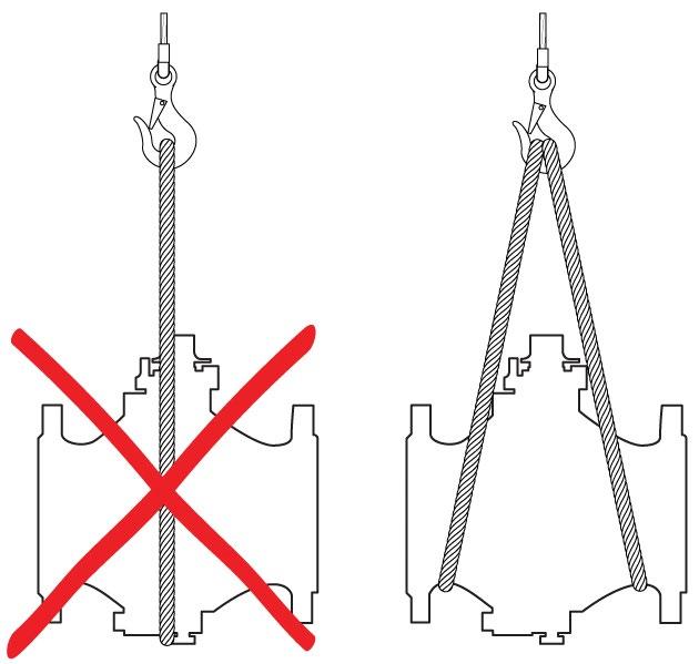
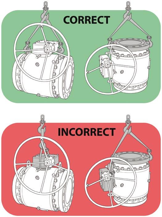
a- To handle the valve use body lugs if applicable or suitable eyebolts. Never handle the valve by yoke or using the lever or actuator or gear box eye bolts. Never lift from bore of valve. Do not lift the valve using only one lifting lug.
b- The end protectors must be removed only immediately before installation. If one of end is not connected to the line for a period of longer than half a day the opened end shall be securely sealed with plastic or wooden cover.
c- For butt weld type valves take care for the following: If brushing or grinding, seal valve conduit (bore) to prevent damage. At the end of such operation clean accurately the conduit. The welding procedure and post-weld treatment shall be performed taking into account the allowable maximum temperature for seats and seals. The welding sequence shall be pre-planned in order to give an acceptable piping load to the valve. Leave valve in full open position to reduce temperature transmission to soft seats. For valves up to 80 NB (3”) use temperature measuring strips. Ensure temperature of body does not go above 180°C.
d- At the end of installation lock the valve full open in order to avoid any movement of the ball before flushing the pipeline.
e- Valves will operate at any angle horizontally or vertically, although it is recommended you install valves in a vertical position with stem pointing upwards for ease of operation, inspection and accessibility.
Australian Pipeline Valve - Installation, Operation and Maintenance Manual 9 EXPANDING SEAL PLUG VALVE DOUBLE BLOCK & BLEED API6D - TWIN SERIES
f- Plug valves are usually bi-directional, and therefore may be installed in either direction. In some cases, ball valves such as ‘metal to metal’ and low temperature valves may be unidirectional, in which case the direction of flow will be indicated on the valve body.
If the ball valve is equipped with a test connection port, make sure that it is fully closed before pressurising the valve.
Local safety regulations must be complied with for transport to the place of installation. Make sure that the valves cannot tilt or slip in any way (see figure below).
2.3 MAINTENANCE PRIOR TO FLUSHING
a- If the period between installation and flushing of the of the pipeline is longer than six months a preventative maintenance operation is suggested.
• Lubricate the stem with fluid protective oil through the stem injector (if applicable). Do not grease lubricate seats as grease may attract debris and damage seats.
• Remove valve from line and remove any debris and reflush.
2.4 FLUSHING THE PIPELINE
Flushing washes away all welding slag, dirt, sand, solids and debris collected in the pipelines during construction prior to turning the valve and potentially damaging the seat. Flushing where deemed necessary is the most dangerous activity for the valve, and it happens before they are put into service. Ball valves are normally not lubricated, however, should it be required to flush potential debris (or lubricate sticky valves) a different practise to the lubrication of either a gate valve or plug valve should be employed. We recommend the following: -
1. Find a good grease for natural gas or your service. The grease must be insoluble. It must be resistant
Australian Pipeline Valve - Installation, Operation and Maintenance Manual 10
EXPANDING SEAL PLUG VALVE DOUBLE BLOCK & BLEED API6D - TWIN SERIES
to breakdown or shearing of the gel structure under high pressure injection and under the pressure between seating surfaces. It must be stable over a wide range of temperatures, and not freeze. It must not react chemically with the fluid and become solid, or rubber like (i.e. polymerize). Depending on the service, the best greases are fully synthetic; if you have any doubt or concern, consult a valve maintenance expert. Field experience has shown that greases and sealants may cause severe problems with the seat and seal arrangement if used regularly during preventative maintenance. If a non-leaking ball valve is lubricated with an adhesive grease/sealant, the floating, spring loaded seats can become stuck within their seat pockets. When the ball floats due to a pressure differential across the valve, the seals cannot track the ball and leakage can occur. Grease manufacturers produce low viscosity synthetic ball valve lubricants such as Clare UK “601-Fluid”. Such light greases offer the following advantages to heavier emergency sealant greases and cheaper brands of light greases:
• Enhanced resistance to hydrocarbon fluids and gases.
• Will not dry out or form a gum like some other greases when used within its application temperature range.
• Will not disrupt the operation of the seat and seal arrangement.
Of course, be warned any type of grease, especially synthetic grease can become hard or sticky causing torque problems and seat spring jamming in which case a line flushing agent like Clare 601 Valve Cleaner may be required. Of course, for leaking seats a heavier sealant like Clare 601 lubricant must be used for temporary emergency sealing.
Beware of greases made of synthetic oil with a mineral thickener. The natural gas (or storage prior to use) washes away the oil, leaving the thickener behind. The thickener is like a powder that caulks or bakes hard on the seats, increasing the operating torque. Always wipe the seats clean as much as possible prior to installation.
Do not operate the valve during flushing or entrained particulates could damage soft seat or enter stem or seat pocket area.
2. Use an appropriate high pressure grease-injection pump, capable of overcoming the pipe pressure and the high pressure build-up caused by the grease itself, during it’s injection in the grease passages.
3. Inject a generous amount of grease in the seats before flushing. The object is to cover them all and to fill the groove between seat carrier and ball with grease. The dirt will get stuck to the grease during flushing, but it will not come inside. And before turning the valve for the first time, inject again a small amount of grease into the seats. A little is enough (1/4 of the normal quantity per seat, see 8.4.1). The dirty grease will be pushed into the pipe by the fresh grease, and the turning action of the ball will drag fresh grease towards the seats, not dirty grease.
4. Do not turn the valve during flushing.
Australian Pipeline Valve - Installation, Operation and Maintenance Manual 11 EXPANDING SEAL PLUG VALVE DOUBLE BLOCK & BLEED API6D - TWIN SERIES Note
2.5 MAINTENANCE POST FLUSHING
a- At the end of flushing operation it may be possible to leave the line full of test fluid and in this case no intervention is required. If the line must be drained proceed as follows:
• Make sure that the valve is in full open position.
• Open plugs and drain it completely. Observe safety plant procedures prior to opening any body plugs in case any remaining fluid or gas is pressurised or trapped in body cavities.
• After draining flush the cavity of valve through the vent plug. Consult an expert on use of special excavation procedures.
• Lubricate the stem with fluid protective oil or grease through the injector (if applicable). (Seat lubrication is only for emergency purposes not for ongoing maintenance).
• Completely tighten all drain and vent plugs. Consult your plant safety procedures and only perform work under supervision of expert valve maintenance personnel.
b- Operate the valve at least 2 times (complete closing and opening operation).
c- Repeat the operation every 6 months if the pipeline is not used.
d- Always get authorisation to partially operate an in-service valve.
Personal injury may result from sudden release of any process pressure. APV recommends the use of protective clothing, gloves and eyewear when performing any installation or maintenance. Isolate the valve from the system and relieve pressure prior to performing maintenance. Never unscrew sealant injection nipples from body, seats or stem as these outlets are exposed to full line pressure and only the in-built check valve in the sealant nipple itself isolates the pressure. Similarly, the body drain and vent valve plugs are exposed to full line pressure if opened. Disconnect any operating lines providing air pressure, control signals or electrical power to actuators.
Natural gas is not usually clean. Natural gas may carry condensates and dirt that gets trapped in the valves, and may damage the internal parts. Also, operation of the valves becomes more difficult. It is true that plant sites do install filters in their system, but experience has proven that no system is perfect. The internal parts of the valve can be partially protected using judicious amounts of grease to fill the cavities. However, other than when flushing or if there is seat leakage, or if valve cannot be opened, no grease should be applied via seat sealant injectors to soft seats as it will attract debris and cause damage. A soft seated valve is always at risk if service is not clean.
Australian Pipeline Valve - Installation, Operation and Maintenance Manual 12 EXPANDING SEAL PLUG VALVE DOUBLE BLOCK & BLEED API6D - TWIN SERIES
2.6 COMMISSIONING
The first year of operation is crucial, because when the pipe is put into service, all debris is pushed downstream, and contaminates the valves along it’s travels. With time, the pipe gets cleaner and initial problems disappear. Strainers or filters should be installed upstream of all soft seated valves.
Remember that plug valves are like the human body; they need ‘exercise’. Keep moving them and lubricating them, and you will have fewer problems. Do not let them have a sedentary life.
3.0 OPERATION
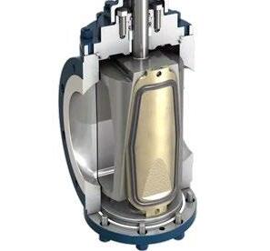
The APV double block twin seal plug valve has dual expanding seals and is a plug-type which has a mechanical means of expanding the seals when seating and retracting them prior to quarter-turn rotation. The resilient seats (Viton, Hycar) are bonded to metal seating slips (No. 13). In opening the valve, the centre plug (No. 12) is raised, thus retracting the seating slips through their tapered dovetail connections. Only after the seating slips are fully retracted perpendicularly from the body seat can the plug, which is mounted on trunnions, be rotated to the open position.
Conversely, in closing the valve, the plug and seating slips are rotated freely, with no plug-to-body contact, until the seating slips are positioned over the ports. Then the plug is driven between the slips, and the tapered surfaces wedge out the seating slips for a positive upstream as well as downstream shut-off. For maximum upstream sealing, it is important to torque the valve closed.
he small APV plug valves are handwheel operated, and require up to 3 turns to open or close. Up to 2 3/ 4 turns expand or retract the slips, while 1/ 4 turn rotates the plug. Large valves operate in a similar manner that they have enclosed weather-proof worm gearing.
The plug lift/lowering/rotation action is performed in the operator assembly. The operator handwheel is rotated clockwise to close, and counter-clockwise to open - similar to other valves. At the top of the valve, a position indicator flag shows the exact lug position. It appears in line with the flow when the valve is open and perpendicular to the flow when the valve is closed. Where APV valves are used for double block-and-bleed service, the body bleed valve may be left open when the APV valve is closed, but must be closed before the APV valve is opened. Since APV valves do hold bubble-tight, for ease of opening in liquid service, it is important to prevent trapped body pressure from exceeding the working pressure of the valve. Therefore, a relief system is required to prevent pressure buildup in the body cavity.
On gear-operated models, the handwheel position may be changed as follows:
Australian Pipeline Valve - Installation, Operation and Maintenance Manual 13
SEAL PLUG VALVE
&
API6D -
SERIES Note
EXPANDING
DOUBLE BLOCK
BLEED
TWIN
EXPANDING SEAL PLUG VALVE DOUBLE BLOCK & BLEED API6D - TWIN SERIES
a. Place APV valve in full open position.
b. Remove gear housing cap screws.
c. Turn handwheel to further open the valve. This will turn gear housing assembly; continue until handwheel comes to desired position and gear housing mounting holes are realigned.
d. Replace gear housing mounting cap screws.
3.1 PRESSURE TEST
APV plug valves can be hydrostatically pressure tested after installation, to full API6D limits per Table 1 below.
3.2 OPTIONAL - “DIFFERENTIAL THERMAL RELIEF” - BLEED SYSTEM
This specification addresses the proper functioning, trouble shooting, and repair of the APV plug valve differential (pressure) thermal relief (DTR) bleed system.
Background
When APV valve is seated and completely fill with a liquid, any slight variation in temperature due to the sun’s rays or ambient thermal fluctuations will cause drastic changes in body cavity pressure resulting from thermal expansion.
While results vary under actual service conditions depending on media, pressure vessel rigidity, and presence of entrapped gas it is known that dangerously high pressures will build up in liquid filled positive shutoff valves. Therefore, the APV in liquid service requires a pressure relief device.
The differential (pressure) thermal relief system is one such automatic “device” and should be included on every automated valve.
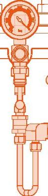
The differential (pressure) thermal relief system is arranged as shown below. A variety of components are used. The relief valve mounted in the centre of the valve body pipes over pressure to the upstream throat of the valve.
The standard relief valve is set to open at 25 PSI on all valves regardless of working pressure. With the valve closed, the relief valve will open at 25 PIS above upstream pressure. This system functions only when the valve is closed.
Australian Pipeline Valve - Installation, Operation and Maintenance Manual 14
TABLE 1 ASME CLASS 150 300 600 COMMENTS Shell Test Pressure (Valve Open) (psig) (kg/cm2) 450 32 1150 81 2250 158 No leakage permitted. Seat Test Pressure (Valve Closed) (psig) (kg/cm2) 319 22 825 58 1650 116 Test upstream & downstream seats. Supplementary (API598) Air Seat Test Pressure (Valve Closed) (psig) (kg/cm2) 80 6 80 6 80 6 Test upstream & downstream seats. No leakage permitted.
A manual body bleed valve is included on the APV as standard. This bleed valve installed in the relief system is opened after the APV valve is closed. Seal effectiveness can be immediately evaluated, after allowing a few seconds for stabilisation of cavity volume due to entrained air or gas. The bleed valve must be closed before the APV valve is opened.
An isolation valve installed in the upstream throat tap is also included. It must be left open to permit relief system to relieve pressure upstream. The isolation valve will be used only for maintenance and troubleshooting which will be explained later. Valve is to be CLOSED ON FOR REPAIR. If closed during normal operation the automatic portion of the relief system (relief/check valve) will be defeated. (The outlet of the relief valve would close when closing the isolation valve).
Valve Operation

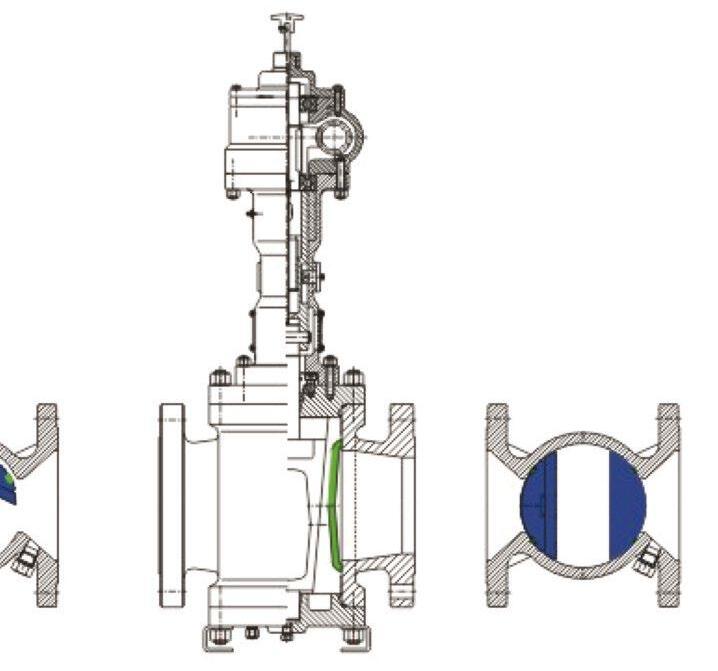
In the fully open position, the resilient seals are positioned out of the flow path and protected within the body of the valve itself.
As the valve is cycled from the fully open to closed position, the plug begins a 90 degree rotation. During the entire rotation of the plug the resilient seals located on both slips are retracted away from the body. This ensures that there is no rubbing or scraping action on these resilient seals during rotation of the plug from the open to the closed position.
Australian Pipeline Valve - Installation, Operation and Maintenance Manual 15 EXPANDING SEAL PLUG VALVE DOUBLE BLOCK & BLEED API6D - TWIN SERIES
4.0 REMOVAL FROM LINE
It is desirable that the maintenance operations are carried out by skilled personnel who are experienced and well trained in standard field techniques and procedures. Be sure that the personnel involved in such operations are aware of fundamental safety rules indispensable for the protection of their own and other people’s safety.
If it is required to remove the valve from the line proceed as follows:
a- Ensure the line is fully depressurised.
b- Partially open the ball in order to depressurise the valve.
c- Remove the drain plug and vent plug. First release vent to ensure no remaining pressurised gas or fluid trapped in cavity. Take safety precautions to avoid personal injury during this procedure. Then carefully remove drain plug once you are sure valve has no remaining fluid or gas in cavity.
d- Keep the plug in the fully open position.
e- Remove the valve from the line. The valve shall be handled by means of lifting lugs fitting on the valve (if applicable). Standard field techniques and procedures are satisfactory to disconnect it from the line.
f- After removal of the valve from the line, clean the valve and seal the ends with plastic or wooden covers.
5.0 GEARBOX REMOVAL
a- Removal (refer to enclosed drawings)
• Unscrew the bolts/nuts.
The actuator or gearbox position stops have been properly set in the shop. Do not alter the setting.
• Lift the gear box to disengage the valve stem and remove it with the plate.
Australian Pipeline Valve - Installation, Operation and Maintenance Manual 16 EXPANDING SEAL PLUG VALVE DOUBLE BLOCK & BLEED API6D - TWIN SERIES
Note
Steam seal body leakage can result in personal injury.
b- Put in position a removable cover to prevent the introduction of dust, sand, etc., in the actuator bushing.
6.0 VALVE DISASSEMBLY
The following should only be performed by an APV approved reconditioner.
Note, The below parts refer to the general drawing in Table 2. This is a general overview drawing only.
Each size & class range does vary so refer to the actual as-built drawing.
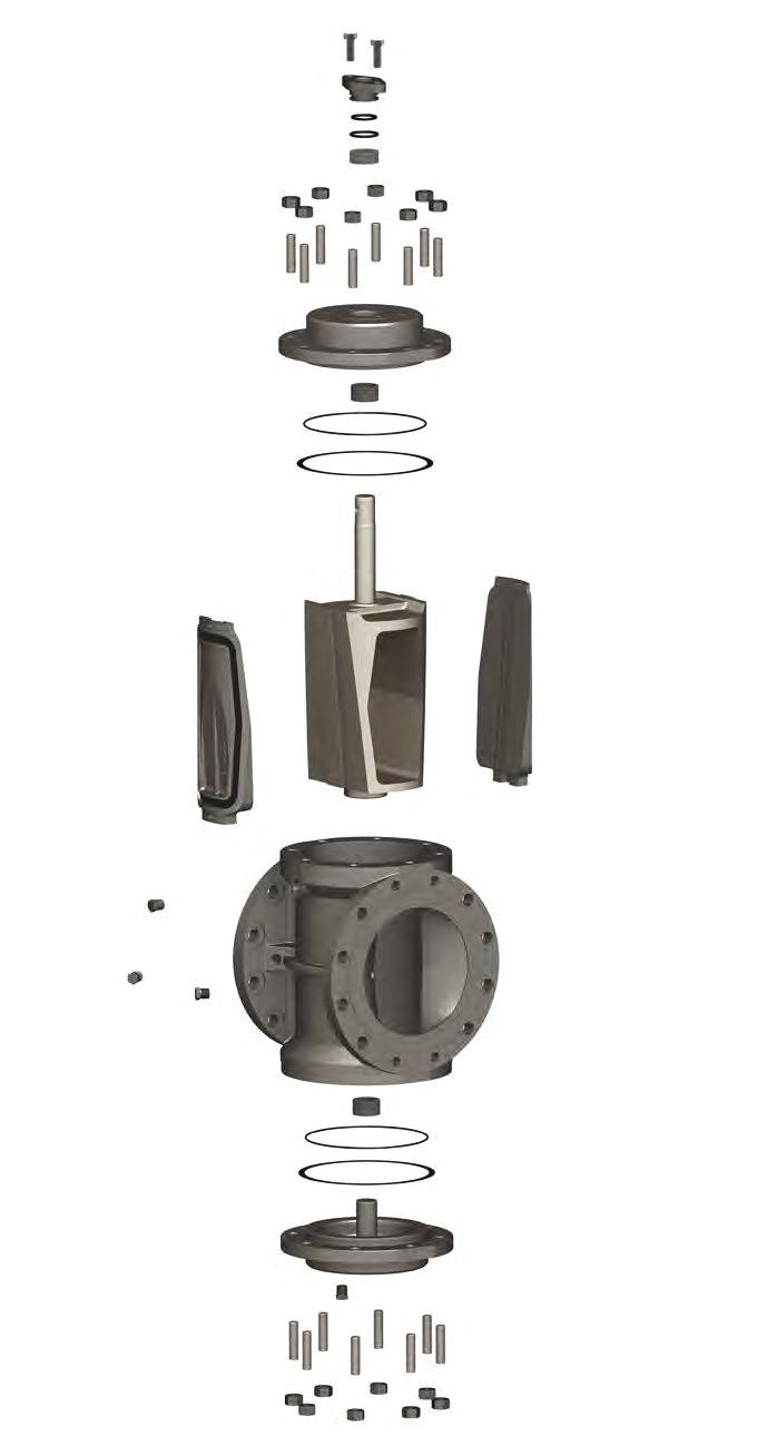
NO. DESCRIPTION
1 Hex Head Bolt
2 Packing Gland
3 O-Ring
4 O-Ring
5 Packing
6 Hex Nut
7 Stud
8 Upper Bonnet
9 Bushing
10 O-Ring
11 Gasket
12 Plug
13 Slip
14 NPT Plug
15 Body
16 Lower Bonnet
Sample only - refer to as built drawing as design varies according to size, class & model variation.
2 4 6 6 7 7 8 3 12 9 9 10 10 14 14 5 13 11 15 11 16 1 Australian Pipeline Valve - Installation, Operation and Maintenance Manual 17
EXPANDING SEAL PLUG VALVE DOUBLE BLOCK & BLEED API6D - TWIN SERIES
TABLE 2 - APV PLUG VALVE ASSEMBLY - TYPICAL
7.0 MAINTENANCE
In cold climates before freezing weather sets in, any possible collection of water below plug or plug trunnion should be drained out through drain plugs (No. 14) Check manual body bleed (no. 23) for zero pressure before removing plugs.
If, at any time, the manual body bleed should indicate an upstream leak which cannot be stopped by ordinary hand force on the handwheel, this must be corrected by one of the following:
a. Operate valve through open - close cycle while fluid is flowing, to try flush out valve body. After several flushing attempts, close valve and check body bleed again. If body bleed still indicates valve leak, check thermal relief assembly before replacing seating slips.
Use extreme caution when venting the body cavity of a pressurised valve.
If the body cavity keeps venting fluid at a constant flow rate for a very long time, it is a signal of bad sealing of the valve seats. For liquid service only a lower drain valve will immediately indicate a leak.
b. To replace seating slips, the line must be drained. Place valve in open position (check body bleed for zero line pressure); then remove lower plate (No. 16) or bonnet (No. 8. APV has both top and bottom entry to facilitate in-line maintenance.
c. Seating slips (No. 13) can be withdrawn from plug dovetails and replaced. It is usually best to replace the gasket (No. 11) and lower plate o-ring (No. 10) or bonnet “O” ring (No. 10) when slips are replaced. If stem packing should fail, it can be changed as follows:
a. Close valve and check body bleed for upstream shut off. Leave body bleed open. If valve is holding tight, then packing can be changed under line pressure. If body bleed shows the valve is not holding upstream, then the line must be bled down in order to proceed with the change.
b. Remove operator as outlined below.
c. Remove packing gland (No. 5) and replace inner and outer o-rings (Nos. 3 & 4).
d. Remove packing rings (No. 5) carefully and replace.
e. Replace operator as outlined below.
Australian Pipeline Valve - Installation, Operation and Maintenance Manual 18 EXPANDING SEAL PLUG VALVE DOUBLE BLOCK & BLEED API6D - TWIN SERIES
To change operator heads:
a. Close APV valve extra tight.
b. Remove snap ring and drive out trunnion pin.
c. Remove housing mounting bolts and lift off the operator.
d Replace new operator in reverse order.
e. Check operation of valve.
f. Lubricate operator every year, while in the open position, with a good grade Lithium-base, extreme pressure (E.P.), multi-purpose grease.
Do not overfill housing with grease
g. APV valves have a thermal body relief valve assembly to relieve body pressure build-up caused by thermal expansion of the liquid media when the valve is in liquid service, to prevent the internal cavity pressure from rising above the shell pressure rating of the valve. The APV valves, as well as other of it’s type, must have a thermal relief system to enable them to be remotely operated by electrical hydraulic actuators.
The standard APV relief assembly contains a thermal relief valve, set at 25 PSI differential that is piped across one of the seating slips.
APV valves with this self-contained thermal relief assembly should be installed with the discharge of the thermal relief valve piped to the upstream side of the valve. If, after the APV valve is installed in the line, it is noticed that the thermal relief assembly is piped to the downstream port, the tubing should be switched to the upstream port.
There is a half-inch manual isolation valve connected between the thermal relief valve and the upstream port. The manual valve should always be left open and is normally closed only for maintenance purposes and hydrostatic testing.
Note
If a leak is indicated at the body bleed valve, the isolation valve should be closed, which will indicate if a leak is from a damaged seat slip or a leaking thermal relief valve. If the leak stops when the isolation valve is closed, the thermal relief valve needs to be replaced.
The other type of relief assembly uses a thermal relief valve piped to the atmosphere. This valve is normally set slightly higher (10%) than the working pressure of the valve and is located adjacent to the body bleed valve.
Please refer to as-built drawing as each size & class can have variations in design.
Australian Pipeline Valve - Installation, Operation and Maintenance Manual
EXPANDING SEAL PLUG VALVE DOUBLE BLOCK & BLEED API6D - TWIN SERIES
19
Australian Pipeline Valve - Installation, Operation and Maintenance Manual NOTES
Australian Pipeline Valve - Installation, Operation and Maintenance Manual NOTES

www.australianpipelinevalve.com.au AUSTRALIAN PIPELINE VALVE® HEAD OFFICE 70-78 Stanbel Road Salisbury Plain South Australia 5109 Telephone +61 (0)8 8285 0033 email: admin@australianpipelinevalve.com.au If you have any requirements in the field of valves, please contact us for a prompt response. Continuous development of Australian Pipeline Valve products may necessitate changes in the design or manufacture process. Australian Pipeline Valve reserves the right to effect any such changes without prior notice. © Australian Pipeline Valve 1990 - 2024 Edition LOCAL DISTRIBUTOR/AGENT IOM APV Plug Expanding