SAFETY INFORMATION
The following general safety notices supplement the specific warnings and cautions appearing elsewhere in this manual. They are recommended precautions that must be understood and applied during operation and maintenance of the equipment covered herein. This manual provides instructions for storing, general servicing, installation and removal of ball valves.
Do not attempt to disassemble a valve while there is pressure in the line. Make sure both upstream and downstream pressures are removed. Disassemble with caution in the event all pressures are not relieved.
To prevent valve distortion, inefficient operation, or early maintenance problems, support piping on each side of the valve.
• A valve is a pressurised device containing energised fluids and should be handled with appropriate care.
• Valve surface temperature may be dangerously too hot or too cold for skin contact.
• Upon disassembly, attention should be paid to the possibility of releasing dangerous and or ignitable accumulated fluids.
• Adequate ventilation should be available for service
Do not use the gate valve in process conditions where the pressure, temperature, media and other technical conditions exceed the limitations set by the valve’s specifications. When handling fluids that could cause damage to human health, the environment or property, the necessary safety precautions to prevent risk must be taken.
APV and it’s resellers refuse any liability for damage to people, property or plant as well as loss of production and loss of income under any circumstances but especially if caused by: Incorrect installation or utilisation of the valve or if the valve installed is not fit for the intended purpose. It is the sole responsibility of the client to ensure the valve type and materials are correctly specified.
Australian Pipeline Valve - Installation, Operation and Maintenance Manual 4 API6D THROUGH CONDUIT SLAB GATE VALVE - AP410-414 SERIES
DURING OPERATION BEAR IN MIND THE FOLLOWING WARNINGS:
a- The graphoil packing and body gasket is very brittle: any twisting or bending shall be avoided.
b- The internal parts of valves (gate, stem, seats) shall be handled with care avoiding scratches or surface damage.
c- All tools and equipment for handling and supporting internal critical sealing parts shall be coated with soft materials.
d- Seats & seals usually include Viton, Devlon, Nylon & Teflon, hence high temperatures and some chemicals will damage sealing components.
e- Never part open valve, valve must be fully open of fully closed or else the seats will be damaged. For all operations make reference to position number on part list of the applicable drawing. The drawing in the Appendix is a general drawing only, for more accuracy refer to the as-built drawings supplied with the order.
SCOPE OF INSTALLATION ACCORDING TO THE TYPE OF FLUID (DANGEROUS FOR THE ENVIRONMENT OR HUMAN HEALTH)
Group 1 Classification
- Current stem packing materials should be specified by the user for the range of products included in Group 1.
- The use of valves without additional safety devices in Group 1 will be the responsibility of the user or the purchaser, as well as the advisability of installing leakage detection systems.
Group 2 Classification
- Carbon steel valves will not be used in corrosive fluid lines.
1.0 PRESERVATION & STORAGE
1.1 STORAGE
a- If storage in the field for a long time before installation is necessary, it is suggested to put valves in a dry and/or covered place. In this case the packaging and end covers integrity is especially important.
b- All the valves are supplied with special plastic ends to cover and protect the internal parts. We recommend you do not remove them during storage period.
c- Valves should be left in the open position (unless actuated and set fail closed).
1.2 PERIODIC MAINTENANCE DURING STORAGE
In case of extended storage, the valves must be inspected and maintained as follows:-
• External surfaces must be inspected to ensure no damage to flange faces, paint finish etc. In case of the presence of rust and/or damaged painting, the area must be cleaned by brushing, degreasing & repainting.

Australian Pipeline Valve - Installation, Operation and Maintenance Manual 5 API6D THROUGH CONDUIT SLAB GATE VALVE - AP410-414 SERIES
• The protection must be restored following the instruction indicated from APV in accordance with the painting cycle used.
• Without any gate movement, the internal surface of the valves must be inspected to check the complete absence of dust, rust, foreign matters and the integrity of lubricant coat. If not satisfactory then clean and lubricate the internal part using a nebulised lubricant.
• After cleaning and lubrication the gate must be operated (close/open complete stroke).
• The gate must be kept in the full open position during installation.
• The end of the valve must be protected using the same end covers.
• We recommend you tropicalise bore and ends of valves if stored in humid or salt air environment.
1.3 ENVIRONMENTAL CONSIDERATIONS
According to ISO 14000 regulations and the environmental policy of APV the recyclability of the components that form part of APV valves is as follows:
Recyclable components:
Metal parts, PTFE (hard), plastic plug (low-density polyethylene).
Non-recyclable components:
PTFE mixed with other compounds (glass-fiber, graphite, etc.), nylon, graphite and graphite mixed with metal.
2.0 INSTALLATION
2.1 VALVE PREPARATION
a- Remove the ends protectors and check accurately the status of the valve as indicated in point 1.2.
b- Prior to shipment, a preservative/corrosion inhibitor may have been applied to the inner body of the valve. This preservative/corrosion inhibitor can be removed with a solvent, provided the solvent used does not affect the seats/seals used in the valve.
c- Do not operate the valve until the following procedures have been fully applied:
• Clean internal conduits.
• After cleaning the gate must be operated (one complete stroke).
• During installation the gate must be kept in the fully open position.
If the valve and actuator are delivered separately, APV recommends utilising a qualified technician to mount the actuator to the valve, make all necessary adjustments, fully test and debugged the unit before installing the valve in the pipeline.
Australian Pipeline Valve - Installation, Operation and Maintenance Manual 6 API6D THROUGH CONDUIT SLAB GATE VALVE - AP410-414 SERIES Note
2.2 VALVE INSTALLATION
a- To handle the valve use body lugs if applicable or suitable eyebolts. Never handle the valve by yoke or using the lever or actuator or gear box eye bolts. Never lift from bore of valve. Do not lift the valve using only one lifting lug.
b- The end protectors must be removed only immediately before installation. If one of end is not connected to the line for a period of longer than half a day the opened end shall be securely sealed with plastic or wooden cover.
c- For butt weld type valves take care for the following: If brushing or grinding, seal valve conduit (bore) to prevent damage. At the end of such operation clean accurately the conduit. The welding procedure and post-weld treatment shall be performed taking into account the allowable maximum temperature for seats and seals. The welding sequence shall be pre-planned in order to give an acceptable piping load to the valve. Leave valve in full open position to reduce temperature transmission to soft seats. For valves up to 100 NB (4”) use temperature measuring strips. Ensure temperature of body does not go above 180°C.
d- At the end of installation lock the valve full open in order to avoid any movement of the gate before flushing the pipeline.
e- Valves will operate at any angle horizontally or vertically, although it is recommended you install valves in a vertical position with stem pointing upwards for ease of operation, inspection and accessibility.
If the gate valve is equipped with a test connection port, make sure that it is fully closed before pressurising the valve.
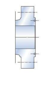
Local safety regulations must be complied with for transport to the place of installation. Make sure that the valves cannot tilt or slip in any way. CORREC T CORREC T INCORREC T
Australian Pipeline Valve - Installation, Operation and Maintenance Manual 7 API6D THROUGH CONDUIT SLAB GATE VALVE - AP410-414 SERIES
CORREC T CORREC T INCORREC T CORREC T CORREC T INCORREC T
f- APV’s preference is that through conduit gate valves be installed in the vertical direction. The horizontal orientation is acceptable as shown below.
Note
It may be necessary to adequately support valve actuation in order to protect the valve and/or actuator from improper weight distribution and excess stress. To ensure actuation mounting and supports are adequate during operation, please contact APV before mounting and installation.
Install the gate valve with the gate segments in the OPEN POSITION. The preferred pressure side of the valve MUST BE INSTALLED TO THE UPSTREAM PIPE as shown below.
g- During commissioning and pipeline flushing, the valve must remain in the full-OPEN position to prevent damage to the internal parts. Impurities and foreign debris entering the valve body may cause damage to sealing surfaces resulting in malfunction.
DOWNSTREAM
PREFERRED FLOW DIRECTION UPSTREAM
To prevent damage to the valve, APV recommends first installing a spool piece instead of the valve whilst flushing the pipeline. If a spool piece is not an option, install strainers at critical locations upstream from the location to remove foreign debris. It is pertinent that the valve remain in the full-OPEN position during flushing.
Australian Pipeline Valve - Installation, Operation and Maintenance Manual 8
THROUGH CONDUIT SLAB
VALVE - AP410-414 SERIES
API6D
GATE
Thermal Relief Assembly MUST vent to the UPSTREAM side of the valve.
2.3 MAINTENANCE PRIOR TO FLUSHING
a- If the period between installation and flushing of the of the pipeline is longer than six months a preventative maintenance operation is suggested.
• Lubricate the stem through the stem injector (if applicable).
• Remove valve from line and remove any debris and reflush.
2.4 FLUSHING THE PIPELINE
Flushing washes away all welding slag, dirt, sand, solids and debris collected in the pipelines during construction prior to turning the valve and potentially damaging the seat. Flushing where deemed necessary is the most dangerous activity for the valve, and it happens before they are put into service. Should it be required to flush potential debris from the seat area, (or lubricate sticky valves). We recommend the following: -
1. Find a good grease for natural gas or your service. The grease must be insoluble. It must be resistant to breakdown or shearing of the gel structure under high pressure injection and under the pressure between seating surfaces. It must be stable over a wide range of temperatures, and not freeze. It must not react chemically with the fluid and become solid, or rubber like (i.e. polymerize). Depending on the service, the best greases are fully synthetic; if you have any doubt or concern, consult a valve maintenance expert. Field experience has shown that greases and sealants may cause severe problems with the seat and seal arrangement if used regularly during preventative maintenance. Of course, be warned any type of grease, especially synthetic grease can become hard or sticky causing torque problems and seat spring jamming in which case a line flushing agent like Clare 601 Valve Cleaner may be required. Of course, for leaking seats a heavier sealant like Clare 601 lubricant must be used for temporary emergency sealing.
If greasing through valve sealant fitting to dislodge debris or to lubricate, beware of greases made of synthetic oil with a mineral thickener. The natural gas (or storage prior to use) washes away the oil, leaving the thickener behind. The thickener is like a powder that caulks or bakes hard on the seats, increasing the operating torque. Always wipe the seats clean as much as possible prior to installation.
Do not operate the valve during flushing or entrained particulates could damage soft seat or enter stem or seat pocket area.
2. The dirty grease will be pushed into the pipe by the fresh grease, and the sliding action of the gate will drag fresh grease towards the seats, not dirty grease.
3. Do not turn the valve during flushing.
Australian Pipeline Valve - Installation, Operation and Maintenance Manual 9 API6D THROUGH CONDUIT SLAB GATE VALVE - AP410-414 SERIES
Note
2.5 MAINTENANCE POST FLUSHING
a- At the end of flushing operation it may be possible to leave the line full of test fluid and in this case no intervention is required. If the line must be drained proceed as follows:
• Make sure that the valve is in full open position.
• Open plugs and drain it completely. Observe safety plant procedures prior to opening any body plugs in case any remaining fluid or gas is pressurised or trapped in body cavities.
• After draining flush the cavity of valve through the vent plug. Consult an expert on use of special excavation procedures.
• Completely tighten all drain and vent plugs. Consult your plant safety procedures and only perform work under supervision of expert valve maintenance personnel.
b- Operate the valve at least 2 times (complete closing and opening operation).
c- Repeat the operation every 6 months if the pipeline is not used.
d- Always get authorisation to partially operate an in-service valve.
Personal injury may result from sudden release of any process pressure. APV recommends the use of protective clothing, gloves and eyewear when performing any installation or maintenance. Isolate the valve from the system and relieve pressure prior to performing maintenance. Never unscrew sealant injection nipples from body, seats or stem as these outlets are exposed to full line pressure and only the in-built check valve in the sealant nipple itself isolates the pressure. Similarly, the body drain and vent valve plugs are exposed to full line pressure if opened. Disconnect any operating lines providing air pressure, control signals or electrical power to actuators.
Natural gas is not usually clean. Natural gas may carry condensates and dirt that gets trapped in the valves, and may damage the internal parts. Also, operation of the valves becomes more difficult. It is true that plant sites do install filters in their system, but experience has proven that no system is perfect. The internal parts of the valve can be partially protected using judicious amounts of grease to fill the cavities.
2.6 COMMISSIONING
The first year of operation is crucial, because when the pipe is put into service, all debris is pushed downstream, and contaminates the valves along it’s travels. With time, the pipe gets cleaner and initial problems disappear. Strainers or filters should be installed upstream of all soft seated valves.
Australian Pipeline Valve - Installation, Operation and Maintenance Manual 10 API6D THROUGH CONDUIT SLAB GATE VALVE - AP410-414 SERIES
Remember that gate valves are like the human body; they need ‘exercise’. Keep moving them and lubricating them, and you will have fewer problems. Do not let them have a sedentary life.
The same recommendations regarding grease injection for flushing (see 2.4) apply for commissioning. By refilling the grease channels multiple times, the dirt is gradually pushed out of the seats. Provided that the grease is properly chosen (see 2.4), it will not damage the valve, and to a certain extent will shield the seats from contamination. Regular cycling is also important, for two reasons: to prevent the seats from getting stuck, and to distribute fresh lubricant over the seating surfaces of the gate and seats. Once the seat is greased, it is a good idea to pump fresh grease into the seat to expel any debris laden grease (see 2.4) before cycling the valve to avoid damage to soft seat inserts. Should you need to apply grease to seats, ensure you then inject fresh grease to dispel any grease which may have attracted contaminants and then partially stroke the valve multiple times to remove as much grease as possible from the seats. After commissioning, once you believe the service is clean you can inject a suitable grease line flushing agent and then partially stroke the valve again. You should consult a valve maintenance specialist as different service, media, pressures, temperatures, etc., can require totally different practises. APV recommends the following programme for start up: -
1. For the first year, inject a small amount of grease into the seats before turning the valve, every time. 2. Cycle the valves periodically as follows:
• For the first month, every week.
• For the second month, every two weeks.
• For the third month, every month, for at least 6 months.
• Then every three months.
Carefully select the type of seat inserts to suit the type of particulates encountered in the media. Nylon and Devlon are hard and resistant to scratching, PEEK is even harder. Teflon® (PTFE) is softer and scratches easier, yet it can have more resilience and ‘memory’ in terms of resistance to permanent indentations but has a lower pressure rating. However, all soft seated valves are only suitable for clean service ‘metal to metal’ seated valves are required for dirty or higher temperature service. Regardless of soft seat materials, valves need to be regularly partially stroked to prevent sticking of seats and accumulation of entrapped debris.
3.0 REMOVAL FROM LINE
It is desirable that the maintenance operations are carried out by skilled personnel who are experienced and well trained in standard field techniques and procedures. Be sure that the personnel involved in such operations are aware of fundamental safety rules indispensable for the protection of their own and other people’s safety. Gate valves are field maintainable, hence to carry out normal maintenance (stem lubrication, stem packing substitution, seat lubrication) it is not necessary to remove it from line
Australian Pipeline Valve - Installation, Operation and Maintenance Manual 11 API6D THROUGH CONDUIT SLAB GATE VALVE - AP410-414 SERIES
Note
(seat lubrication is only for emergency purposes not for maintenance).
If it is required to remove the valve from the line proceed as follows:
a- Ensure the line is fully depressurised.
b- Partially open the gate in order to depressurise the valve.
c- Remove the drain plug and vent plug. First release vent to ensure no remaining pressurised gas or fluid trapped in cavity. Take safety precautions to avoid personal injury during this procedure. Then carefully remove drain plug once you are sure valve has no remaining fluid or gas in cavity.
d- Keep the gate in the fully open position.
e- Remove the valve from the line. The valve shall be handled by means of lifting lugs fitting on the valve (if applicable). Standard field techniques and procedures are satisfactory to disconnect it from the line.
f- After removal of the valve from the line, clean the valve and seal the ends with plastic or wooden covers.
Stem seal body leakage can result in personal injury. In an emergency, injecting grease into the grease sealant injection nipple fitted to stem (where fitted) may temporarily cause the leakage to cease but the valve should be removed from the line for repair as soon as possible.
When removing the safety cap of the grease fitting, be careful not to unscrew the complete grease fitting out of the body, because it is under pipe pressure. Use a back-up wrench.
4.0 GEARBOX REMOVAL
a- Removal (refer to enclosed drawings)
• Unscrew the bolts/nuts.
• Lift the gear box to disengage the valve stem and remove it with the plate.
b- Put in position a removable cover to prevent the introduction of dust, sand, etc., in the actuator bushing.
5.0 VALVE DISASSEMBLY
The following should only be performed by an APV approved reconditioner.
Note, The below parts refer to the general drawing labelled Diagram 1. This is a general overview drawing only. Each size & class range does vary so refer to the actual as-built drawing.
Australian Pipeline Valve - Installation, Operation and Maintenance Manual 12
API6D THROUGH CONDUIT SLAB GATE VALVE - AP410-414 SERIES
Check the stem sealing area for pressurised process fluids even after the valve has been removed from the pipeline, particularly when removing packing hardware or sealing rings.
6.0 INSPECTION AND REPAIRS
The following inspection and maintenance procedures of valve components should be performed by a professional valve repairer. Replace any parts that are damaged with genuine APV spare parts.
The sampled diagram labelled Diagram 1 only shows the main parts. The Bill of Material varies according to size, class & trim, hence refer to as-built drawing.
If a gasket or seal is disturbed while removing or adjusting soft parts, APV recommends installing a new gasket or seal. A proper seal is required to ensure optimum operation.
6.1 BOLTS, NUTS AND THREADED COMPONENTS
a- All bolts, nuts, and threaded particulars shall be cleaned with kerosene, dried and lubricated with protective oil. The body bolts should have a copper based anti-seize grease applied. To ensure grease does not dry or wash out and does prevent corrosion protective plastic nut caps with grease nipples are available.
b- The threads should be visually inspected to verify the integrity of the components.
7.0 VALVE ASSEMBLY
The sample drawing labelled Diagram 1 is used as a reference, however, refer to actual as-built drawing as the Bill of Material varies according to size, class and trim.
7.1 VALVE LUBRICATION
For components that need to be lubricated use grease IP Bimol Grease or similar.
7.2 GEARBOX MOUNTING TO VALVE
a- Assemble the gear support with the valve.
b- Insert the actuator/gear on the support with the valve.
c- Screw and tighten the studs/nuts actuator.
Australian Pipeline Valve - Installation, Operation and Maintenance Manual 13 API6D THROUGH CONDUIT SLAB GATE VALVE - AP410-414 SERIES
7.3 PRESSURE TEST
a- Move the gate in the half position.
b- Pressurise the valve body. The body hydrostatic test should be performed at a pressure 1.5 times the maximum rating pressure in accordance with API6D.
c- With the gate in the fully open or closed position the maximum seat hydrostatic test pressure should be performed at a pressure 1.1 times the maximum pressure rating in accordance with API6D. In addition a low pressure pneumatic test of 700KPA should be performed in accordance with API6D. Seats should be tested bi-directionally.
8.0 OPERATION & MAINTENANCE
The valve is only intended to block or allow flow through the pipeline. The valve should only be used in either fully open or fully closed position. Do not use this valve to regulate flow by partially opening or partially closing the valve. The valve should not stay in a semi-open or semi-closed state for more than two minutes.
8.1 OPERATION INSTRUCTION
a- Hand wheel and gear operated gate valve have to be fully opened and closed to check the valve is correctly operating.
b- In the case of automated valves, the instructions from the actuator’s manufacturer shall be supplied separately. In this case, automated valves shall be operated with the required energy source (electric, pneumatic, hydraulic) to check correct functioning.
c- Do not change any settings such as position stops or speed or torque governing devices.
d- Clockwise rotate the handwheel to CLOSE the valve, rotate counter-clockwise to OPEN the valve.
e- When operating a gate valve, APV does not recommend the use of any leverage tool opening or closing the valve. Carefully observe the position of indicator during operation. When the position indicator shows OPEN or CLOSED, rotate the handwheel in the opposite direction one half turn to release the pressure between the stem and drive nut.
f- The APV gate valve is not designed to be used as a throttle valve.
g- If necessary, with the valve fully CLOSED, cavity pressure can be relieved through the bonnet vent fitting.
Australian Pipeline Valve - Installation, Operation and Maintenance Manual 14
API6D THROUGH CONDUIT SLAB GATE VALVE - AP410-414 SERIES
Nominal Pressure (Class) Test Pressure at Normal Temperature (PSI) Hydrostatic Shell Test Hydrostatic Seat Test High/Low Pressure Back Seat Gas Seat Test CL150 450 325 325/80 80 CL150 1125 825 825/80 80 CL150 2225 1650 1650/80 80 CL150 3350 2450 2450/80 80 CL150 5575 4075 4075/80 80 CL150 9275 6800 6800/80 80
Important: In the event that the gate valve body cavity needs to be depressurised, please refer to through conduit gate valve body bleed procedure 8.5.
Always wear approved safety gear and face away from the bonnet when relieving pressure from the valve.
h- To remove the foreign debris from the valve, remove the drain plug from the bottom of the valve body. Reinstall the drain plug when cleaning is complete.
8.2 MAINTENANCE
8.2.1 Cleaning and lubricating the stem
a- IF LINE CONDITIONS PERMIT, cycle the valve to the full OPEN position.
b- Remove stem protector.
c- Use a wire brush to clean the stem threads and thoroughly remove any dust, dirt or debris.
d- Check condition of threads for wear or damage.
e- Using a lithium based general purpose grease with a minimum 150 viscosity grease lubricate the thread.
f- To ensure even grease distribution over the stem and drive nut cycle the gate OPEN and CLOSED several times.
g- Return the valve to the desired operating position.
h- Replace stem protector.
(For lubrication frequency and procedure for the actuators please refer to manufacturer’s recommendations).
8.2.2 Seat Lubrication/Sealant
a- Twin secondary sealant injection ports are fitted in the middle of the valve body. In the case of seat sealing surface damage or leakage, a grease gun can be used with an approved sealant to inject the seats.
b- The pressure required to fully inject sealant into the seat/gate surfaces should not exceed 3000 psi over the line pressure. There will be some pressure needed to pump the grease through the gun, hose and extended piping. The amount could be several pounds of pressure more in colder weather. Please note the following example:
Pressure to pump grease: 13,780 kPa
Line pressure: 6,890 kPa
Amount required above: 2,067 kPa
Total amount in cold weather: 22,048 kPa
c- Lubricating the seats on a through conduit gate valve is not necessary however, this will ensure smooth operation. When lubricating the seats and gate surfaces, cycle the gate OPEN and CLOSED
Australian Pipeline Valve - Installation, Operation and Maintenance Manual 15 API6D THROUGH CONDUIT SLAB GATE VALVE - AP410-414 SERIES
API6D THROUGH CONDUIT SLAB GATE VALVE - AP410-414 SERIES
several times to evenly lubricant both surfaces.
d- Return the gate to either the full OPEN or full CLOSED position and inject an additional amount of lubricant to complete the process.
e- APV recommends for buried valves, a minimum of 4 cups of lubricant per valve once extended lines are filled.
f- While APV does not generally recommend a lubricant, we do recommend containing Climax Valve Lubricants with the specifics of the product in the line for a lubricant best suited for the intended service.

8.2.3 Stem Seal/ Packing Maintenance
a- In the event of stem packing leakage, CLOSE the valve and release the cavity pressure.
b- Remove the stinger from the packing injection fitting. Insert the pressure relieving stinger tool to relieve any stem packing pressure.
Australian Pipeline Valve - Installation, Operation and Maintenance Manual 16
Figure 1: Secondary Seat Lubricant/Sealant Injection System
API6D THROUGH CONDUIT SLAB GATE VALVE - AP410-414 SERIES
c- Once pressure is removed and the relief tool has been removed, remove the plug from the packing relief port.
d- Using a grease gun, inject stem seal packing into the packing injector fitting until fresh packing is seen coming through the relief port.
e- Reinstall the relief port plug. Add additional packing until the pressure in the packing gland stabilises
Over pressurising the injectable packing will distort packing, making the valve difficult to operate.

Australian Pipeline Valve - Installation, Operation and Maintenance Manual 17
Stem Stem Packing Stem Packing Injection Fitting Stem Yoke Lantern Ring Stem Packing
PACKING BOX PRESSURE PSIG Valve Pressure Class Packing Box Pressure (PSIG) 150 13,263 kPa (1925 psi) 300 17,914 kPa (2600 psi) 400 20,325 kPa (2950 psi) 600 25,321 kPa (3675 psi) 900 32,727 kPa (4750 psi) 1500 47,541 kPa (6900 psi)
Figure 2: Packing Injection (Design/fitment varies depending on size/class specification)
API6D THROUGH CONDUIT SLAB GATE VALVE - AP410-414 SERIES
0°C is the temperature water will freeze. However, some frozen water hydraulics generated by fluids frozen solid.
then tighten the injector stinger. Please see the Packing Box Pressure PSIG table below for required pressures.
8.2.4 Cold Temperature Maintenance
Allowing freezable fluids to be trapped inside the valve will result in damage to the valve when the fluid freezes.
APV through conduit gate valves are manufactured with ISO standard mounting plates for manual or automation installations.
Correct actuator calibration is critical for proper valve performance and longevity. Incorrect TRAVEL LIMIT and TORQUE LIMIT settings can result in catastrophic valve failure!
8.3 ACTUATION
Important: APV recommends that all actuation is installed and calibrated in a controlled testing environment. Utilise a hydro-test to simulate the targeted operating conditions while setting TRAVEL LIMITS and TORQUE LIMITS.
8.3.1
The APV Slab gate valve is a “travel position seated” design. The travel stops are set at the factory.
Australian Pipeline Valve - Installation, Operation and Maintenance Manual 18
Note
Pressure Exerted By Frozen Fluids Temperature (C) Internal Pressure 0°C 101 kPa -1°C 14,469 kPa -4°C 48,230 kPa -7.5°C 87,227 kPa -12.5°C 138,186 kPa -15°C 159,262 kPa -17.5°C 179,850 kPa
NOTE: Eliminate trapped water in your system to avoid system damage Note
If actuation is to be installed after shipment from APV, IT IS CRITICAL THAT THE SLAB DOES NOT DROP TO THE BOTTOM OF THE VALVE DURING ACTUATION INSTALLATION! THIS MAY RESULT IN SEAT DAMAGE.
8.3.2
To protect the seats, ensure the slab is above the closed position prior to actuation installation.
8.4 TROUBLE SHOOTING GUIDE
Stem packing leakage
Leakage in grease injection and waste valve
The gate will not CLOSE
Difficult to OPEN or CLOSE
Leakage in bonnet flange
Sealing incompletely to upstream and downstream (the pressure in middle cavity cannot relieve to low pressure)
Imbalance of operation
Damage to packing
Damages to ball, spring and sealing ring
Screw cap is not tight
Medium frozen in the bottom
Debris obstruction in bottom of valve
Valve has not been opened or closed for a long time, the seats and gate tied tightly
Dry stem
Medium frozen in the cavity
Pipeline distorted
Bonnet bolts loose
Damage to gasket
Inject stem packing
Replace the damaged components
Tighten screw cap as necessary
Heating
Remove debris through bottom drain plug
OPEN and CLOSE the valve rapidly several times
till the gate is loosened, then OPEN or CLOSE the valve to the required position
Inject lubricant as necessary
Heating
Eliminate the distorting restriction of pipeline
Tighten bonnet bolts as necessary
Replace the gasket
The gate is not CLOSED completely CLOSE the valve
Damage to sealing surface
Damage to O-ring
Dry bearing
Possible damage to drive nut or bearing
Replace the damaged sealing element
Replace O-ring
Inject the distorting as necessary
Replace the damaged parts Note
To relieve pressure from the internal cavity (body) of the valve while under pressure, please follow this procedure carefully. Operate the valve into the full torqued CLOSED position.
8.5 BODY BLEED PROCEDURE
Whilst through conduit valves are block & bleed capable, the valve needs to be ordered and tested as a block & bleed valve. A special bleed system should be specifically plumbed as per diagram below. This characteristic is used to:
a- Ensure that the seats are providing an effective seal, or
b- Drain or flush the body cavity of an in-service gate valve.
Australian Pipeline Valve - Installation, Operation and Maintenance Manual 19 API6D THROUGH CONDUIT SLAB GATE VALVE - AP410-414 SERIES
Problem Possible
Reason Action
Note
Use extreme caution when venting the body cavity of a pressurised valve.
If the body cavity keeps venting fluid at a constant flow rate for a very long time, it is a signal of bad sealing of the valve seats. For liquid service only a lower drain valve will immediately indicate a leak.
8.5.1
a- Operate the valve to the CLOSED position.
b- CLOSE upstream drain valve, tightly.
c- Make sure the drain valve (see before drain) is in the OPEN position.
d- Double check the valves again to insure they are in the proper position.
e- Lightly loosen the body bleed fitting plunger (‘B’ below) to allow slow release of pressure from the cavity.
Please make sure all persons are clear of the fitting opening during venting. Pressure will begin to decrease and flow will lessen as valve body pressure is released.
Note
If pressure does not bleed down, CLOSE fitting (‘B’ below) and operate valve again to the CLOSE position to insure proper closure. Reopen fitting (‘B’ below) and allow pressure to finish venting.
Australian Pipeline Valve - Installation, Operation and Maintenance Manual 20 API6D THROUGH CONDUIT SLAB GATE VALVE - AP410-414 SERIES

DIAGRAM 1
Thermal relief system with bonnet vent
f- Once venting is complete, CLOSE fitting (‘B’ above) tightly, then operate the valve to the OPEN position and OPEN valve ‘A’ to allow the thermal relief system to operate as designed.
8.5.2 Draining Procedure
The purpose of draining the body cavity is to bleed out all the liquid collected in the body cavity. Even in gas service, some condensate, compressor oil and other residues may get trapped in the body cavity after a while. We recommend to drain the body cavity once a year.
Drain the liquids into a suitable bucket to avoid releasing them to the environment. Keep your working area clean. The cavity can be exposed to line or cavity pressure, wear protective eye wear.
To drain the body cavity, proceed as follows:
1. Operate the valve to the fully open or fully closed position, whichever is more convenient for you.
2. Turn loose the head of the drain fitting (18) located at the bottom of the body, to bleed liquids trapped in the body cavity. We recommend a special drain valve specified for this task.
It will take some time to bleed the body cavity. It depends on the size of the fitting, pressure in the body cavity and compressibility of the fluid.
If there are hydrates in gas service, the drain fitting may freeze during high-pressure draining. Work slowly and ensure that the pressure trapped in the body cavity has been completely released, by opening and closing the drain fitting several times.
Australian Pipeline Valve - Installation, Operation and Maintenance Manual 21 API6D THROUGH CONDUIT SLAB GATE VALVE - AP410-414 SERIES
B A C
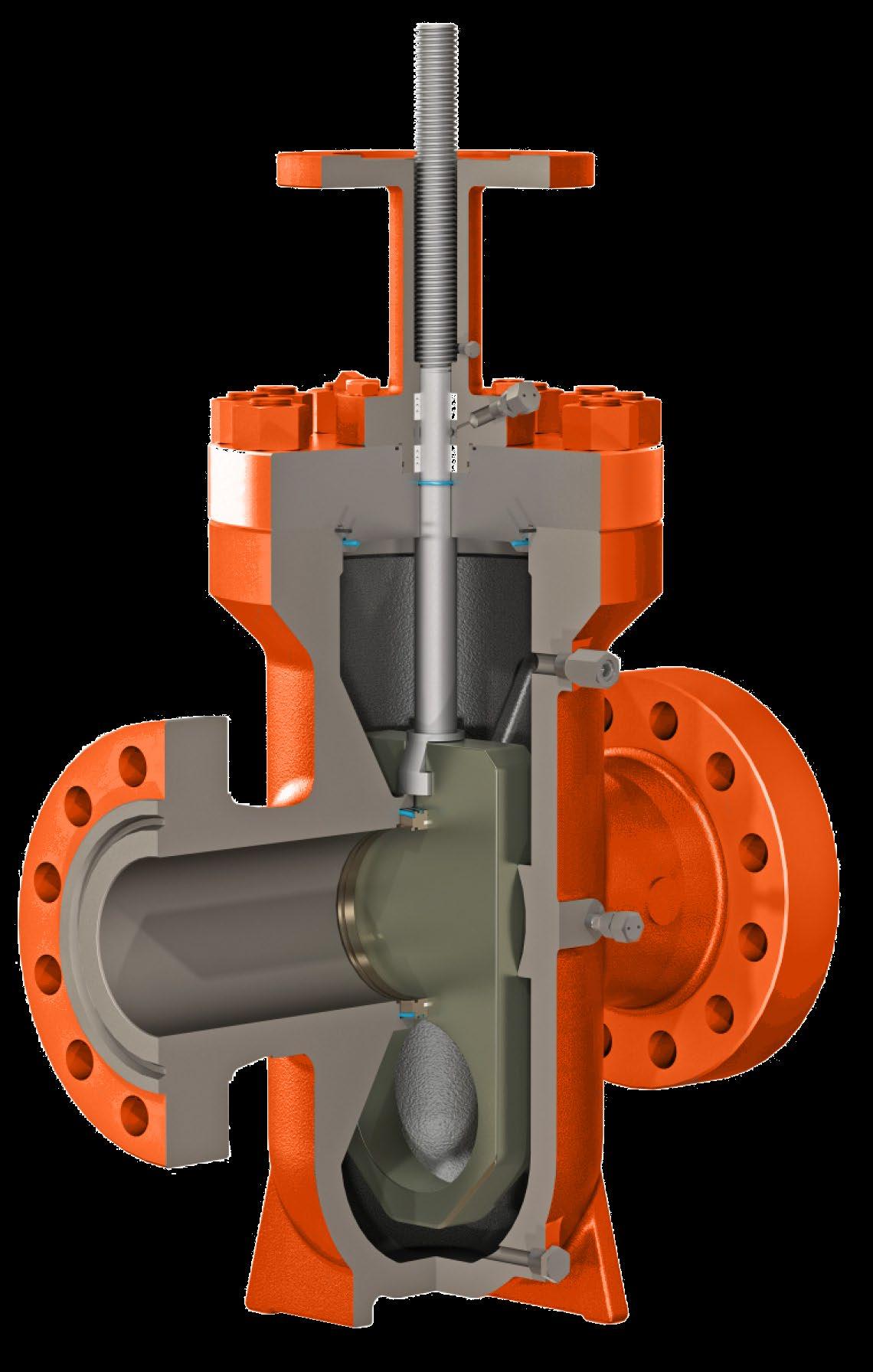
9.0 OVERVIEW DESIGN FEATURES
OVERVIEW API6D THROUGH CONDUIT GATE VALVES

Through conduit Full bore

The through conduit opening design provides full flow passage and allows for the smooth passing or pipeline pigs. Pressure drop through the valve is no greater than that through an equal length of equal diameter pipe.
External pressure relief system for cavity over pressure protection
Due to the double tight sealing isolation design for expanding gate valve, cavity pressure can increase significantly through thermal expansion of fluid in the cavity. A body cavity thermal relief system can be provided to relive this excess body cavity pressure.
In Line repairable
The top entry design allows for access to all internal parts if maintenance is required with the valve still in the pipeline.
Ease of on-line stem packing maintenance
Top and bottom Chevron PTFE packing + lantern ring is the standard stem seal equipped with a stem injector with integrated check valve. Injectable packing material can be injected directly into the packing box through the injector to enhance stem sealing while the valve is under


Australian Pipeline Valve - Installation, Operation and Maintenance Manual 22 API6D THROUGH CONDUIT SLAB GATE VALVE - AP410-414 SERIES
Slab Gate
Expanding Gate
API6D THROUGH CONDUIT SLAB GATE VALVE - AP410-414 SERIES
pressure.
Emergency sealant injection on seats
Provision of seat injectors with integrated check valve provides emergency back up sealing. Additionally, an inner check valve is installed in front of the seat injector to prevent blow out in case of wrong operation. If a seal surface is damaged by foreign matter, valve leakage can be eliminated by using a sealant injected into a specially designed groove in the seat ring assembly. The secondary seat sealant injection backup provides a peace of mind to users who demand reliable block valve service until the valve can be properly serviced. Seats may be lubricated by injecting lubricant to enhance service life and reduce operating torque.
API6D SLAB GATE VALVE

Australian Pipeline Valve - Installation, Operation and Maintenance Manual 23
Double block and bleed (DBB)
Double sealing established by initial plastic-to-metal contact in addition to metal-to-metal contact, both upstream, downstream. In the closed position, both upstream and downstream pressures energize the seats to form a tight seal on both seats simultaneously. This allows the body cavity to be manually bled.
Pressure energised seats
As the upstream pressure increases, the upstream seat is pushed against the slab gate (piston effect), and subsequently the slab gate pushes against the downstream seat, creating a tight seal between both seats and the slab gate. In the absence of line pressure, the energized o-rings behind the seats provide the seating force on the slab gate to maintain a tight effective seal. A sot seat insert in each seat is protected by the metal sealing surfaces in full contact with the gate, in both open and closed positions, completely isolated from the flow stream, greatly extending the seat life.
Cavity over pressure self-relieving
When the medium trapped in the body cavity expands as a result of the thermal expansion, the pressure buildup will push the upstream seat back into it’s recess and relieves to the upstream through the gap between the seat and the slab gate.
Protection of seat faces
Seat faces are not exposed to the flow stream and in full contact with the gate, in both open and close position, greatly expanding seat life.


When the valve in the closed position with equal pressure in the valve, the energized seat O-Ring on both seats will push the seat rings against the gate to provide an initial soft-tometal sealing.
When the line pressure is applied to the valve, the gate will be pushed against the downstream seat until the gate compresses the soft seat insert and forms soft-to-metal and metal-tometal double seal. The downstream O-ring provides the seal between the downstream seat and body. The force of line pressure acting on the upstream seat against the gate provides a soft-to-metal seal, and the upstream seat O-ring provides the seal between the upstream seat and body.
When the valve cavity pressure exceeds line pressure due to thermal expansion, the upstream seat is forced back into its recess and the excess pressure in the body cavity is relieved between the seat and the gate into the line.
Australian Pipeline Valve - Installation, Operation and Maintenance Manual 24
AP410-414 SERIES
API6D THROUGH CONDUIT SLAB GATE VALVE -

Features
Saf-T-Seal®* style
Through conduit design with minimum flow resistance
Double sealing replaceable seat
Locking device
Backseated Stem
Body thermal relief system upon request
Stem extension upon request
Double block and bleed upon request
Soft seat or ‘Metal to Metal’


Australian Pipeline Valve - Installation, Operation and Maintenance Manual 25 API6D THROUGH CONDUIT SLAB GATE VALVE - AP410-414 SERIES 15 14 33 44 42 47 9 45 20 26 2 27 7 21 36 1 3 18 49 12 29 25 11 22 10 8 28 5 16 4 23
Ring Type Joint ≥ 600lb Spiral Wound Gasket 300lb Metal Backup Graphite Gasket 150lb Part Name Carbon Steel to ASTM Alloy Steel to ASTM Stainless Steel to ASTM 1 Body A216 WCB A352 LCB A352 LCC A217 WC6 A217 C5 A217 C12 A351 CF8 A351 CF8M A890 4A 2 Bonnet A216 WCB A352 LCB A352 LCC A217 WC6 A217 C5 A217 C12 A351 CF8 A351 CF8M A890 4A 3 Gate A105 A350 LF2 A350 LF2 A105 A105 A105 A182 F304 A182 F316 A182 F51 4 Seat A105 A350 LF2 A350 LF2 A105 A105 A105 A182 F304 A182 F316 A182 F51 5 Seat Insert RPTFE / PTFE / Nylon M / Devlon / Viton / Peek or Metal to Metal 7 Stem A276 420 A276 420 A276 420 A276 420 A276 420 A276 420 A182 F304 A182 F316 A182 F51 8 Backseat A276 420 A276 420 A276 420 A276 420 A276 420 A276 420 A182 F304 A182 F316 A182 F51 9 Yoke A216 WCB A352 LCB A352 LCC A217 WC6 A217 C5 A217 C12 A351 CF8 A351 CF8M A890 4A 10 Packing Plate A276 420 A276 420 A276 420 A276 420 A276 420 A276 420 A182 F304 A182 F316 A182 F51 11 Lantern Ring A276 420 A276 420 A276 420 A276 420 A276 420 A276 420 A182 F304 A182 F316 A182 F51 12 Stem Nut A439 D2 B150 C61900 14 Indicator Steel 15 Dustproof Cover Steel 16 Spring Steel 18 Drain Fitting 316SS 316SS 316SS 316SS 316SS 316SS 316SS 316SS A182 F51 20 Stem Sealant Injection Assembly 21 Seat Sealant Injection Assembly 22 Packing Non-metal 23 O-Ring Viton 25 Graphite Packing Flexible Graphite 26 Stud A193 B7 A320 L7 A320 L7 A193 B16 A193 B16 A193 B16 A193 B8 A193 B8M A194 B8MLCuNa 27 Nut A194 2H A194 7 A194 7 A194 4 A194 4 A194 4 A194 8 A194 8M A194 8MLCuNa 28 Stud A193 B7 A320 L7 A320 L7 A193 B16 A193 B16 A193 B16 A193 B8 A193 B8M A194 B8MLCuNa 29 Nut A194 2H A194 7 A194 7 A194 4 A194 4 A194 4 A194 8 A194 8M A194 8MLCuNa 33 Nut A194 2H A194 7 A194 7 A194 4 A194 4 A194 4 A194 8 A194 8M A194 83LMCuNa 36 Injection Check Valve Assembly 42 Nut A194 2H A194 7 A194 7 A194 4 A194 4 A194 4 A194 8 A194 8M A194 8MLCuNa 44 Handwheel Ductile 45 Bearing Steel 47 Gland Steel 49 Nut A194 2H A194 7 A194 7 A194 4 A194 4 A194 4 A194 8 A194 8M A194 8MLCuNa *Saf-T-Seal® is a registered trademark of Cameron®. APV is not associated, endorsed or affiliated with Cameron® in any way Materials DIAGRAM 2
API6D THROUGH CONDUIT SLAB GATE VALVE - AP410-414 SERIES
Specifications
Basic Design: API6D ASME B16.34
Face to Face: API6D
End Flange:
2”-24” ASME B16.5
26”- 40” ASME B16.47
B.W End: ASME B16.25
Test and Inspection: API6D & API 598
Manufacturing to NACE MR0175 on request
Gear Operator:
150LB ≥ 20”
300LB ≥ 16”
600LB ≥ 12”
900LB ≥ 10”
1500LB ≥ 8”
2500LB


Australian Pipeline Valve - Installation, Operation and Maintenance Manual 26
≥ 4”
W (RF) Close H W d Bypass Option
L2 (BW) (RTJ)
L1