PLUG
Quality is Our First Priority.
Consistent product quality and a proven track record makes Australian Pipeline Valve a dependable choice where total reliability is the number one concern.
Since its founding, APV’s philosophy has been focused on quality. Our valves are manufactured in full compliance to worldwide standards (such as ASME/ANSI, API, EN, ISO, BS, AS).


ANSI - AMERICAN NATIONAL STANDARD INSTITUTE
ANSI - B 46. 1
ANSI - B 2. 1
ANSI - B 16. 5
ANSI - B 16. 10
ANSI - B 36. 10M
ANSI - B 16. 25
ANSI - B 16. 34
ANSI - B 31. 1
ANSI - B 31. 3
ANSI - B 31. 4
ANSI - B 31. 8
- Surface - Texture
- Pipe - Threads
- Pipe Flanges and Flanged Fittings
- Face to face Dimensions of Valves
- Welded and Seamless Wrought - Steel Pipe
- Buttwelding - Ends
- Steel Valves - Flanged and Buttwelding Ends
- Power - Piping
- Chemical Plant and Petroleum - Refinery - Piping
- Liquid Transportation System - For Liquid Petroleum Gas
- Gas Transmission and Distribution Piping System
API - AMERICAN PETROLEUM INSTITUTE
API - 6A
API - 6D
API - 598
API - 599
API - 6FA
API - 607
BS - BRITISH STANDARD
BS - 5353
BS - 5146
BS - 2080
BS - 1504
BS - 6755
- Specification for Wellheads and Christmas Tree Equipment
- Specification for Pipeline Valves
- Testing for Valves
- Steel Plug Valves for refinery Use
- Specification for Fire Test for Valves
- Specification for Fire Test for Valves
- Plug Valves for the Petroleum and Petrochemical Industries
- Inspection and Test of Steel Valves for Petroleum Industries
- Face to Face, Centre to Face - End to End n Steel Valves
- Specification for Steel Castings for Pressure Purposes
- Part. 1 - Testing of Valves(Specify. for production pressure testing requirements)
MSS - MANUFACTURING STANDARDISATION SOCIETY
MSS - SP 6
MSS - SP 25
MSS - SP 44
MSS - SP 45
MSS - SP 55
MSS - SP 61
- Standard Finish for Contact Face of Pipe Flanges
- Standard Marking System for Valves
- Steel Pipe Line Flanges
- By Pass - and Drain Connection Standard
- Quality Standard for Steel Casting Visual Method
- Hydrostatic - Testing of Steel Valves
NACE - NATIONAL ASSOCIATION CORROSION ENGINEERS
NACE - MR.01.75
- Sulfide Stress - Cracking - Resistant Metallic Materials for Oilfield Equipment
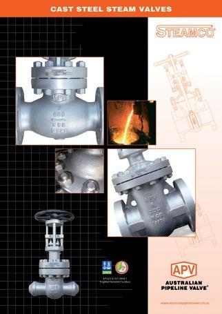
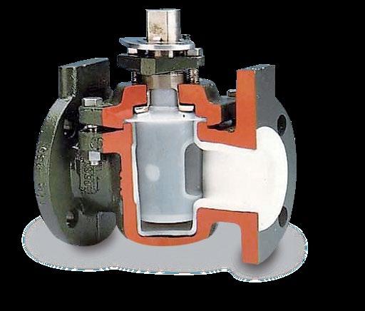
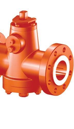
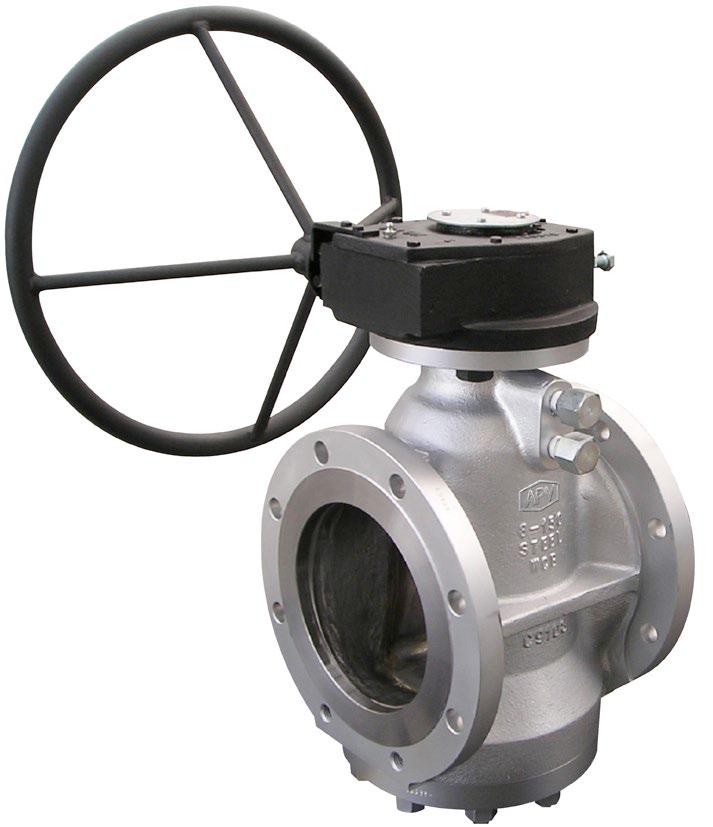
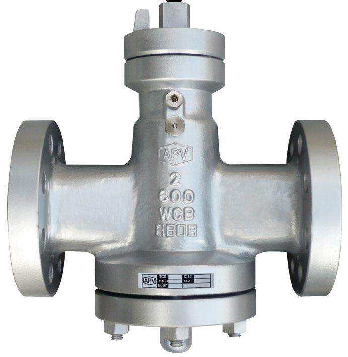
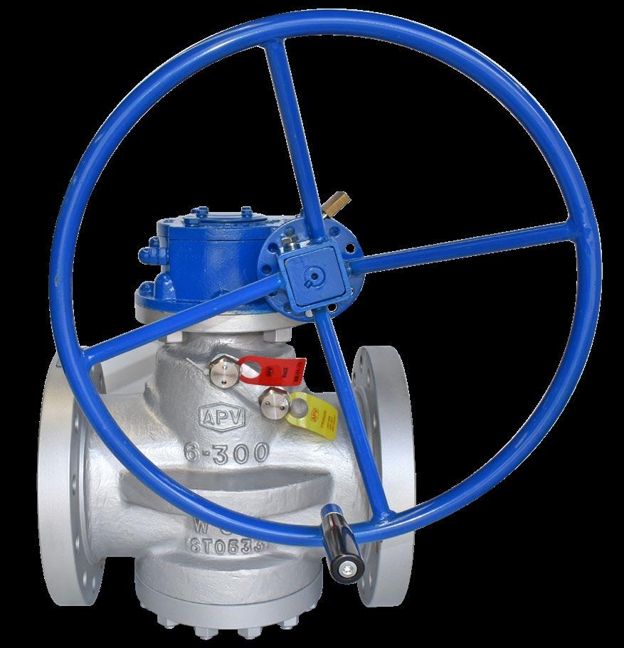
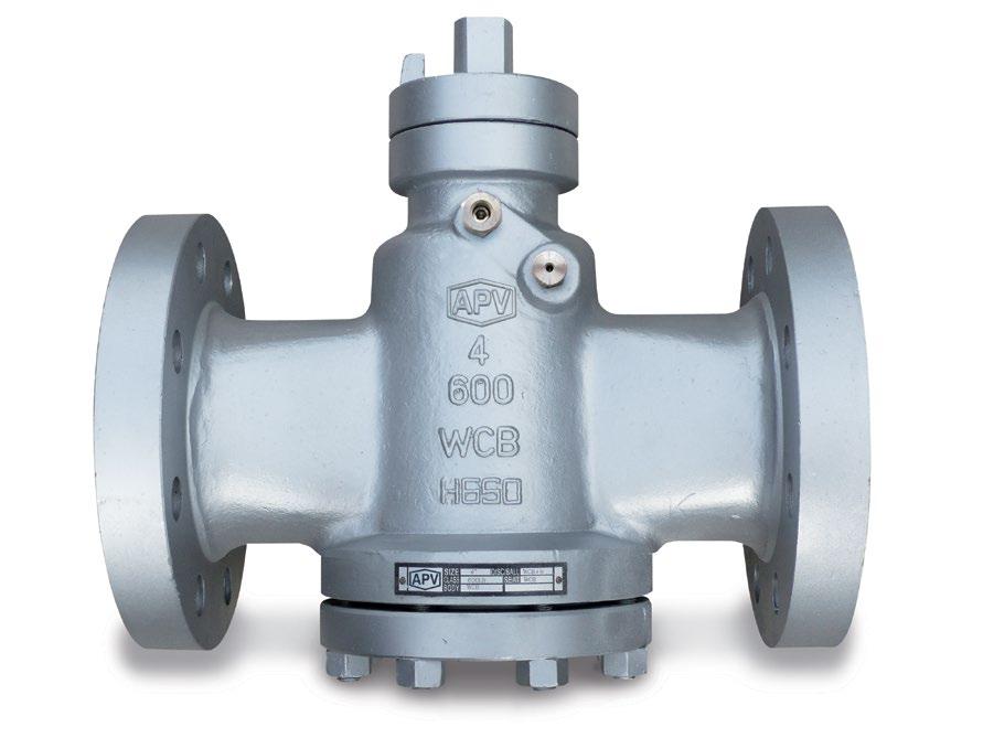
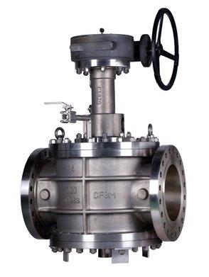
Australian Pipeline Valve Plug Valves are manufactured to cover a wide range of applications.
APV Quarter Turn Plug Valves are excellent for consistent and accurate flow control of gases and viscous liquids can be designed from corrosion resistant materials to meet the needs of abrasive media, even in high temperature and high pressure applications.
Excellent for gas, but also ideally suited for viscous liquids, APV plug valves regulate fluid flow with the use of conically tapered or cylindrical plugs that can be rotated inside the valve body.
APV plug valves are available in three versions: short, regular and venturi patterns. With a compact face to face dimension, short plug valves are suitable for applications where some flow rate reduction can be accepted. Regular pattern plug valves maintain flow with minimal loss and have a longer face to face dimension. When the flow rate is not critical, venturi pattern plug valves minimise pressure drop with a long lead in and out of the port.
STANDARD
• Lubricated Standard type Plug Valves.
• Lubricated Inverted Taper Pressure Balanced High Performance Plug Valves.
• Class 150 to 2500 and API 2000 to 10,000 psi
SPECIAL
• Class 150-300 & 600 three ways Transflow Pattern Lubricated Plug Valves.
• Class 150 four ways transflow Pattern Lubricated Plug Valves.
• Class 150-300-600 Full Jacketed Lubricated Plug Valves.
All Australian Pipeline Valve products are normally available in:
A216 WCB, WCC OR ASTM A105N
• Standard Carbon Steel which are supplied in 0.22% Maximum Carbon content and specified for standard service at temperatures from - 20°C up to + 232°C (-20°F + 450°F). Plugs are normally in Carbon Steel, nitrided or hardened or ENP.
ASTM A352 LCB OR LCC
• Low temperature service suitable from - 46°C to + 232°C (-50°F + 450°F) - normally used for below zero temperatures to - 46ºC must have a minimum average charpy “V” notch impact strength a / 15 foot / Lb.
NACE MR.01.75.
• In natural gas it is possible to encounter small amounts of Hydrogen Sulfides (H2S) which may cause corrosion. The phenomenon is normally known as “Hydrogen Sulfide Embrittlement” or “Sulfide Stress Cracking”. The absorption of Hydrogen from part of steel causes ductility which, when added to other elements of stress caused by the service itself, may cause failure of the forged or cast component. Steels with yield strengths above 621 Mpa (90,000 PSI) or with hardness over 22 rockwell (235 Brinell) may be subject to “Sulfide Stress Cracking”. In Nace MR.01.75 all basic material components are properly treated in order to remain bellow the hardness of 22 rockwell. In such a case, plugs are electro nickel coated or hardened to prevent galling action.
• A 18.12 stainless steel material which contains Molybdenum is suitable for service temperature from -232°C to + 371°C (- 450°F to 700°F). Normally used for valves for high temperature service or where high corrosion resistance is needed.
SPECIAL
• Trim in 13% Chr. - 316 - Monel, Stellite No. 6 (coating). Body in WC6, F51, CF8M, ENP etc.
• Optionally available, Xylan™or LoMu® style (similar) PTFE impregnated anti-friction coating on plug & stem for superior corrosion resistance with the added advantage of reduced torque. Xylan™ is a PTFE based compound frequently used to coat valve components to provide offshore corrosion resistance. F6a/410 Stainless Steel is also available for superior hardness characteristics while being an effective anti-corrosive material.
MATERIALS
Carbon Steel A105 A216WCB/WCC Max C 0.25%
Duplex steel
Super duplex steel
UNS S31803 A890 A182 F51 (Duplex 22% Cr)
UNS S32750
A890 A182 A182 F55 (Super Duplex 25% Cr)
Alloy 20
S31803 A182 F51†
S31803 A182 F51†
S32760
S32750 A182 F55†
S32750 A182 F55† UNS S32750
N08020 A351 CN7M
N08020 A351 CN7M†
† Hardened/Nitrided or ENP+PTFE based anti-friction treatment.
S32750 UNS S322760†
S32760
A
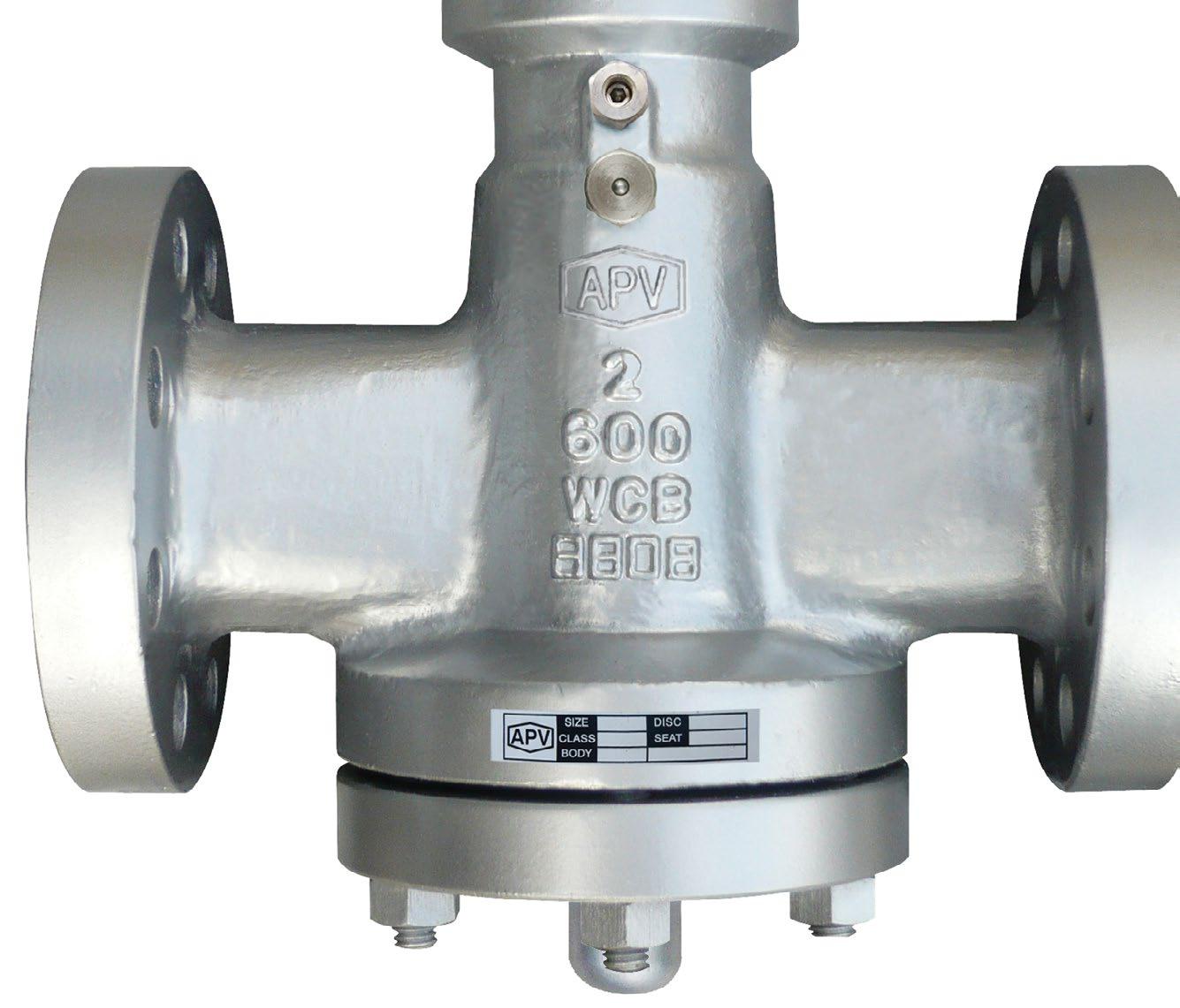
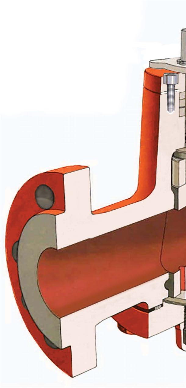
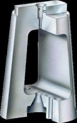
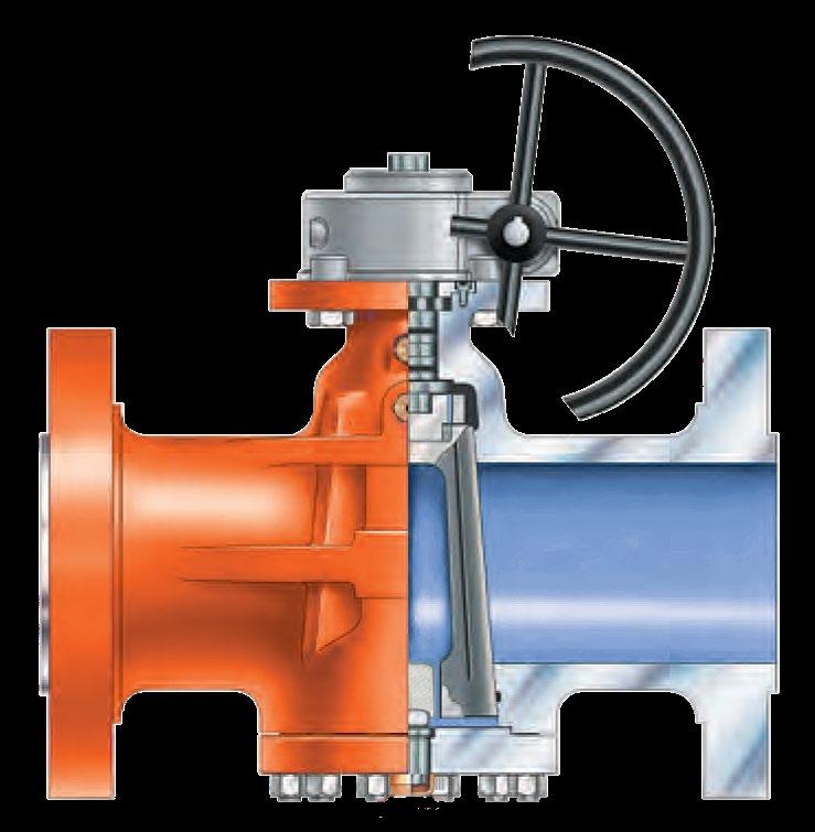
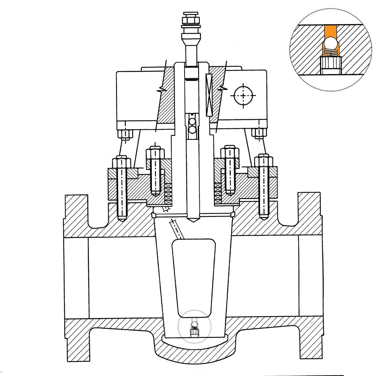
Body – Heavy duty proven design with no cavities. Wall thickness to ASME B16.34 and API 6D. Sealant system grooves provide a complete sealant system groove around ports. Extra body stiffening (as required according to size & class) prevents the phenomenon of flexing in plug valves which causes seat leakage
Stem – Anti blow out + Electroless Nickel Plating (HV500) hardness for low torque, abrasion resistance and Ra 0.8 µm smoothness ensuring low emissions
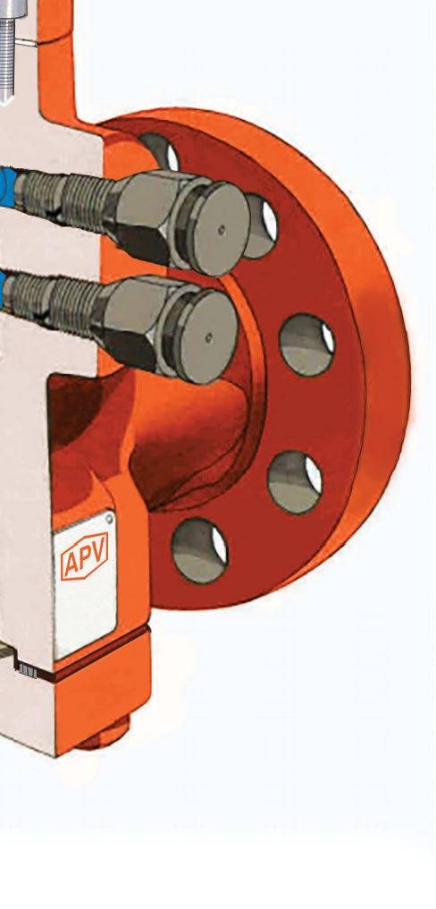
Stem Packing Injector – Emergency stem sealant injection point. Isolated from main line pressure sealant is contained within gland seal area. C/w internal one-way check valve
Gland & Stem Sealing – Fugitive emission & firesafe certified Chesterton 1622 graphite packing. The triple barrier stem seal system and pre-loaded packing provides a long maintenance life. Packing can be adjusted if needed. Furthermore, stem smoothness Ra 0.8µm and stuffing box smoothness Ra 1.6µm ensures ultra low emissions.
Body Sealant Injector – Maintains bubble tight shut-off for the life of the valve. C/w internal one-way check valve
Equaliser Joint – Prevents side loads for efficient stem toplug connection
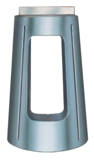
Plug – Metal-to-metal wide seating area with Ni-hard or ENP treatment for low torque & abrasion resistance
Cover Seals – Metal for long life and increased fire safety + spiral wound body gasket for zero leakage
Plug Balancing – designed to pre-load the plug to prevent vibration or thermal recycling from wedging the plug into the body taper regardless of installed position combined with Balance Holes, (as required per size & class) ensuring pressure equalisation between the port and area around plug


Plug Loading Screw – Factory set to ensure seat tightness with low torque, with weatherproof cap

Two O-rings as well as a Primary Thrust Seal below stem ensure pressure is isolated


Australian Pipeline Valve plug valves are available in three different patterns to meet the valve needs of most piping systems.
Short Pattern
Same face to face dimensions as gate valves

Regular Pattern
Offers the largest port opening in a trapezoidal configurationclose to a full pipe port area
Venturi Pattern
Has a smaller port than the other two patterns. It is lower in cost and flow contours maximise the hydraulic efficiency
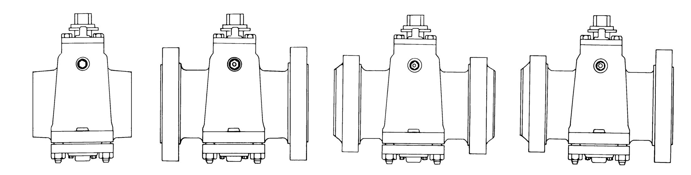
Australian Pipeline Valve plug valves are available with threaded, flanged, butt weld or flanged x butt weld ends. Flanges are provided in either raised face or ring joint ends.

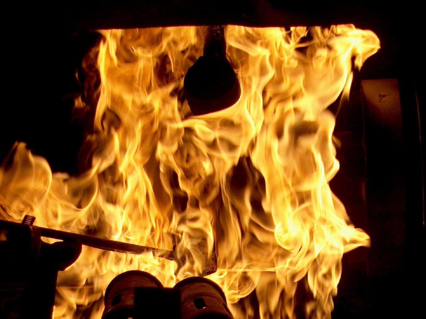
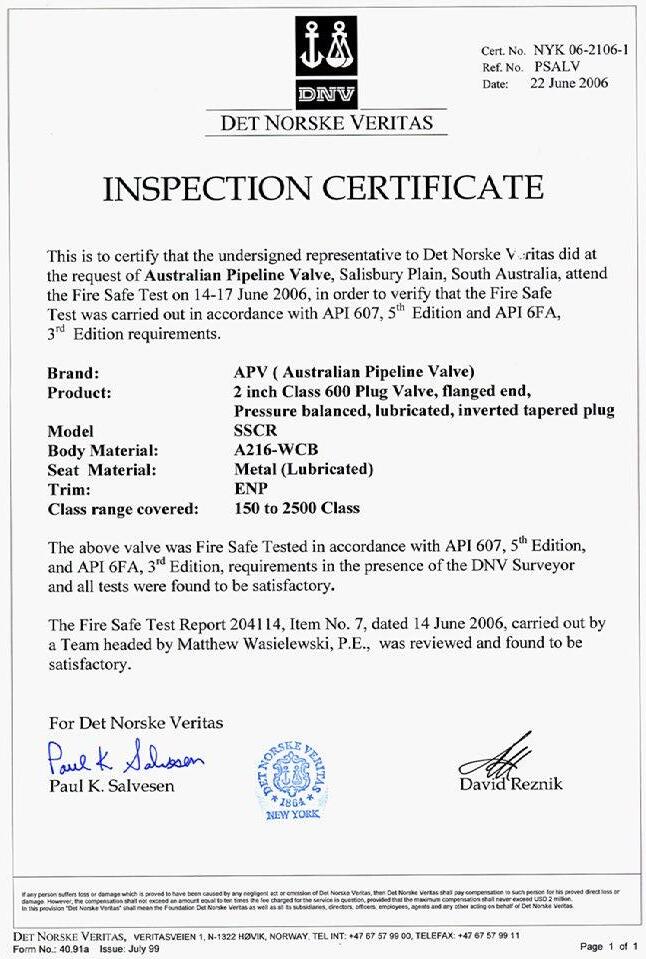
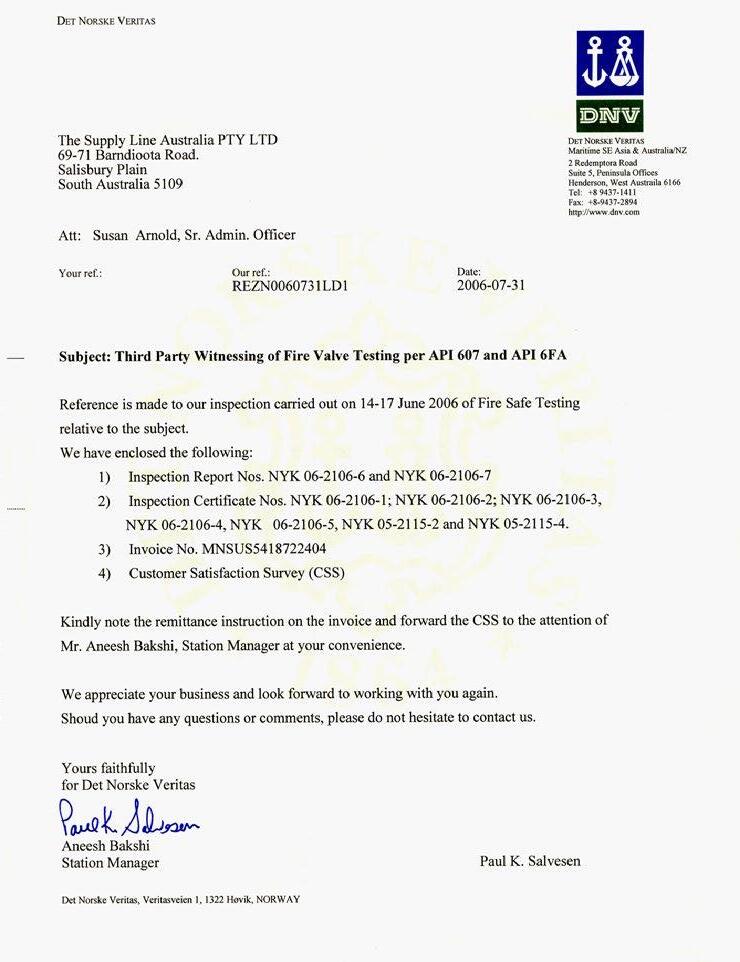
DNV WITNESSED
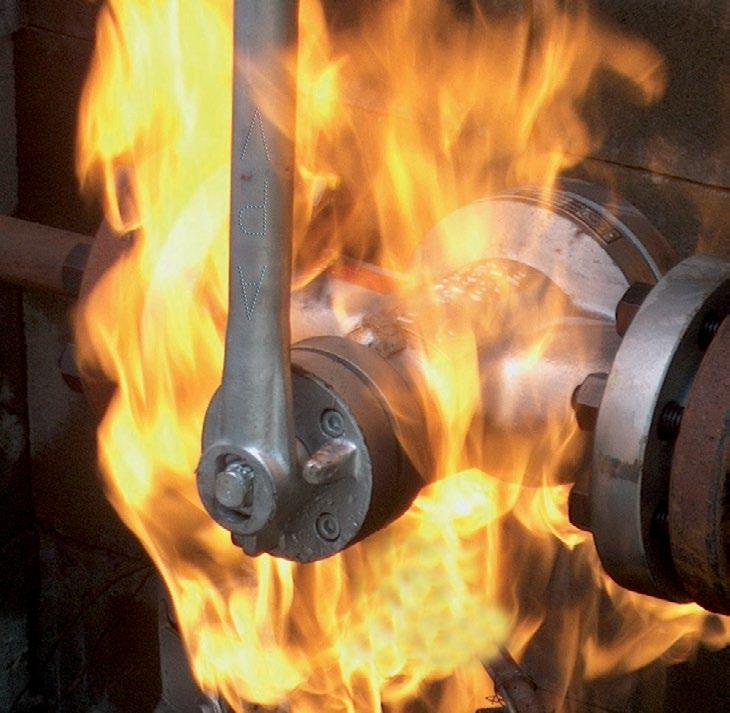
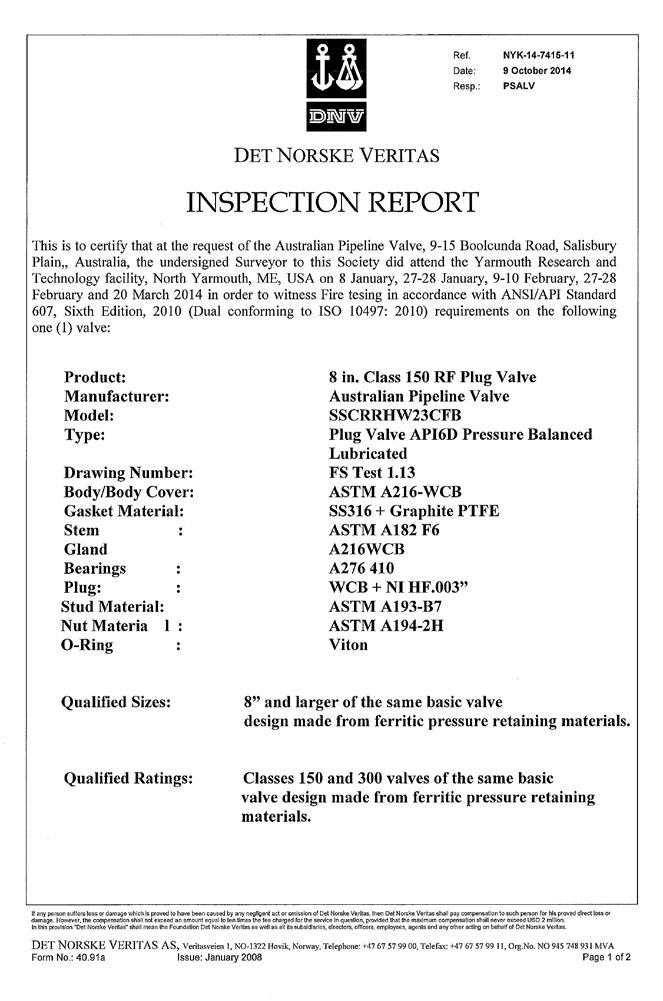
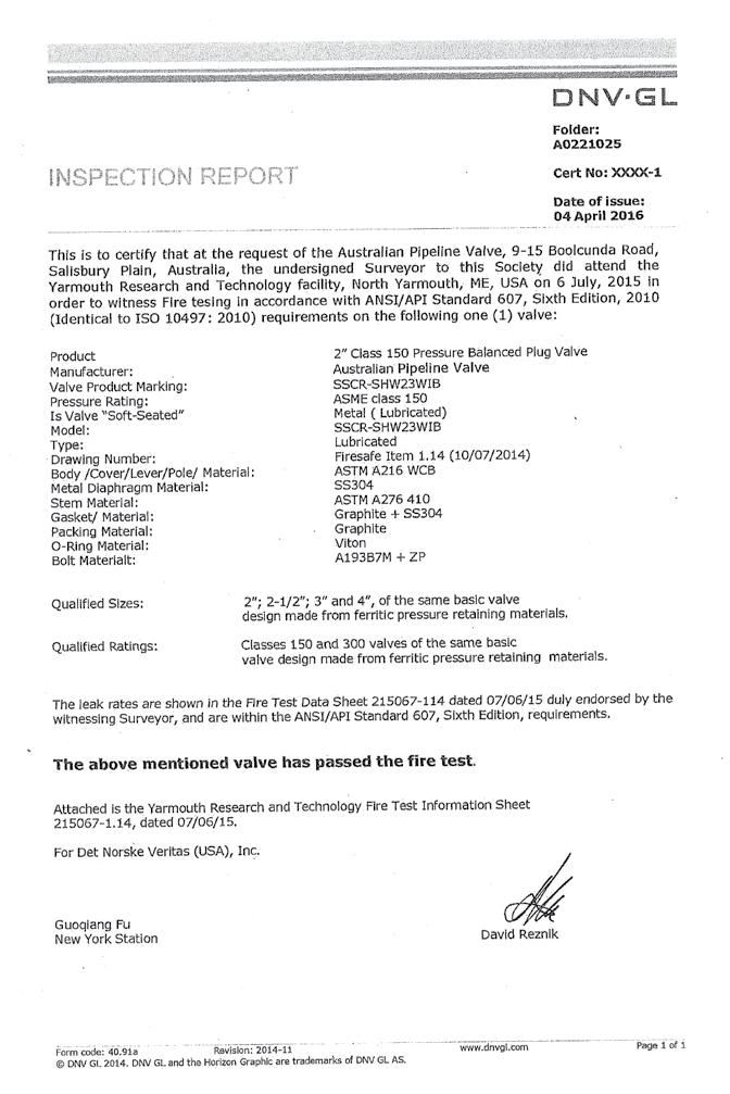
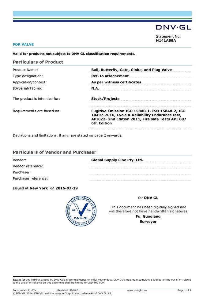
Australian Pipeline Valve was one of the first brands in the world to achieve firesafe certification to the latest fifth edition of API 607 as well as the latest edition of API 6FA and now also one of the only companies in the world to hold firesafe certification to the 6th edition of API 607.


ANSI CLASS 150 to 2500

FIRESAFE CERTIFIED API 607 5TH & 6TH
EDITION, API 6FA AND ISO 10497
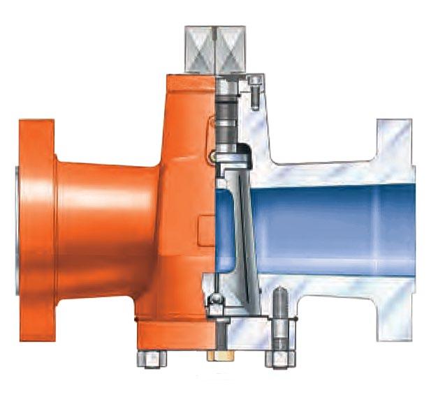
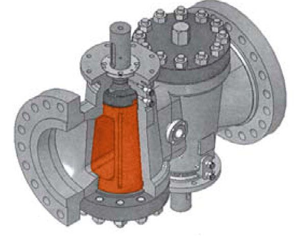
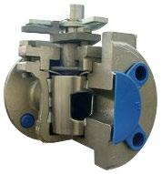
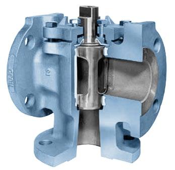
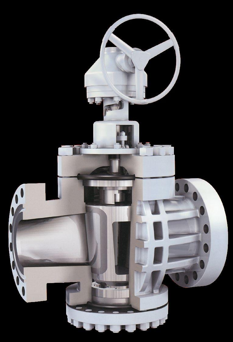
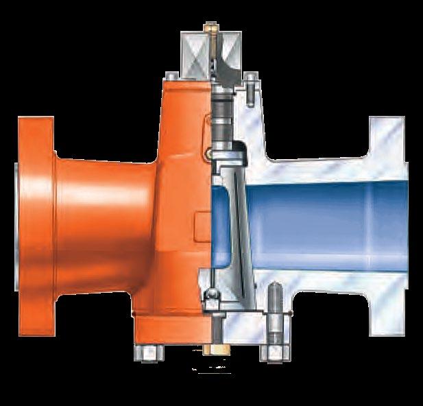
Pressure balanced plug valves are used where pulsating or static high pressures are present. The benefit a dynamic pressure balanced inverted plug gives is that it ensures equalised pressure between the plug and upper and lower body chambers. Pressure is balanced by two holes in the plug which connects the plug port with the lower and upper cavities, as required according to size and class. The hole in the upper end is provided with a check valve so the pressure is always equal to the large end cavity and it is always equal to or greater than the line pressure in the small end cavity.
COMPARISON CHART: APV SSCR VS CONVENTIONAL PLUG VALVE Performance Feature
Pressure balanced low torque design
Safe (API 6FA & API 607)
seats
(APV Sealed Port Sealant System)
turbulence*
port
abrasive/erosive service
CO2 service
H2S service
wedging design
Inverted tapered plug
Unpressurised area at stem
Smooth, Contoured Flow Passages for an unobstructed flow
Ability to adjust the plug-in-line, under pressure
Flow
*Applies to regular pattern not Venturi pattern.
BORE AREA PRESSURE BALANCED
• A regular pattern provides an open area / port size conforming to API 6D and API 599 of approximately 60% to 70% (depending on size and class). 150NB and over can have a slightly smaller port size, can be as low as 46%. Venturi pattern is as low as 40%.
• Full Circular 100% port also available on request.
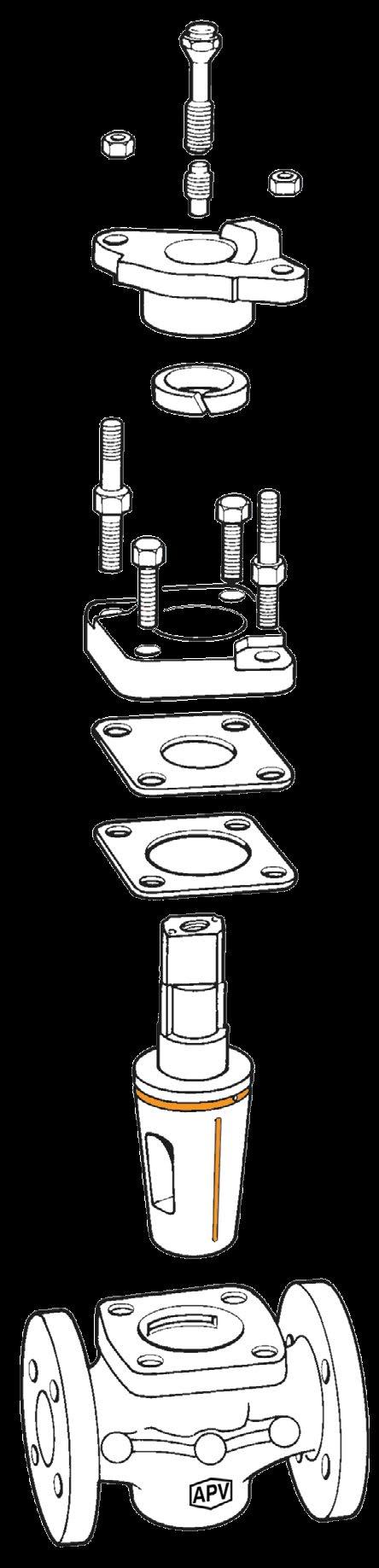
Stop Plate Retainer
Indicator Stop Plate
Socket Head Cap Screw
Stop Bolt
Top Retaining Gland Flange
Firesafe Packing
Stem Sealant Fitting, GBH Grease
Fitting, GBH Body
• Ease of maintenance.
• Regular regreasing ensures ease of operation and resists corrosion whilst ensuring no seat leakage.
• Leak tightness & safety of the operating system is assured by the provision of a check valve in the lubrication injection fitting. An additional check valve is installed into the lubrication duct.
• Firesafe API 6FA, API 607.
Stem O-Rings
Thrust Bearing Stem
Equaliser Ring
Centering Support Ball Head
Retainer Thrust Support Seat
Upper Diaphragm Plate
Lower Diaphragm Plate
Gasket - Spiral Wound
Lower Cover Flange
Plug Loading Screw
Plug Loading Screw Cover Studs
Heavy Hex Nuts
Typical example only, design varies according to size & class
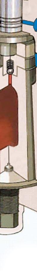
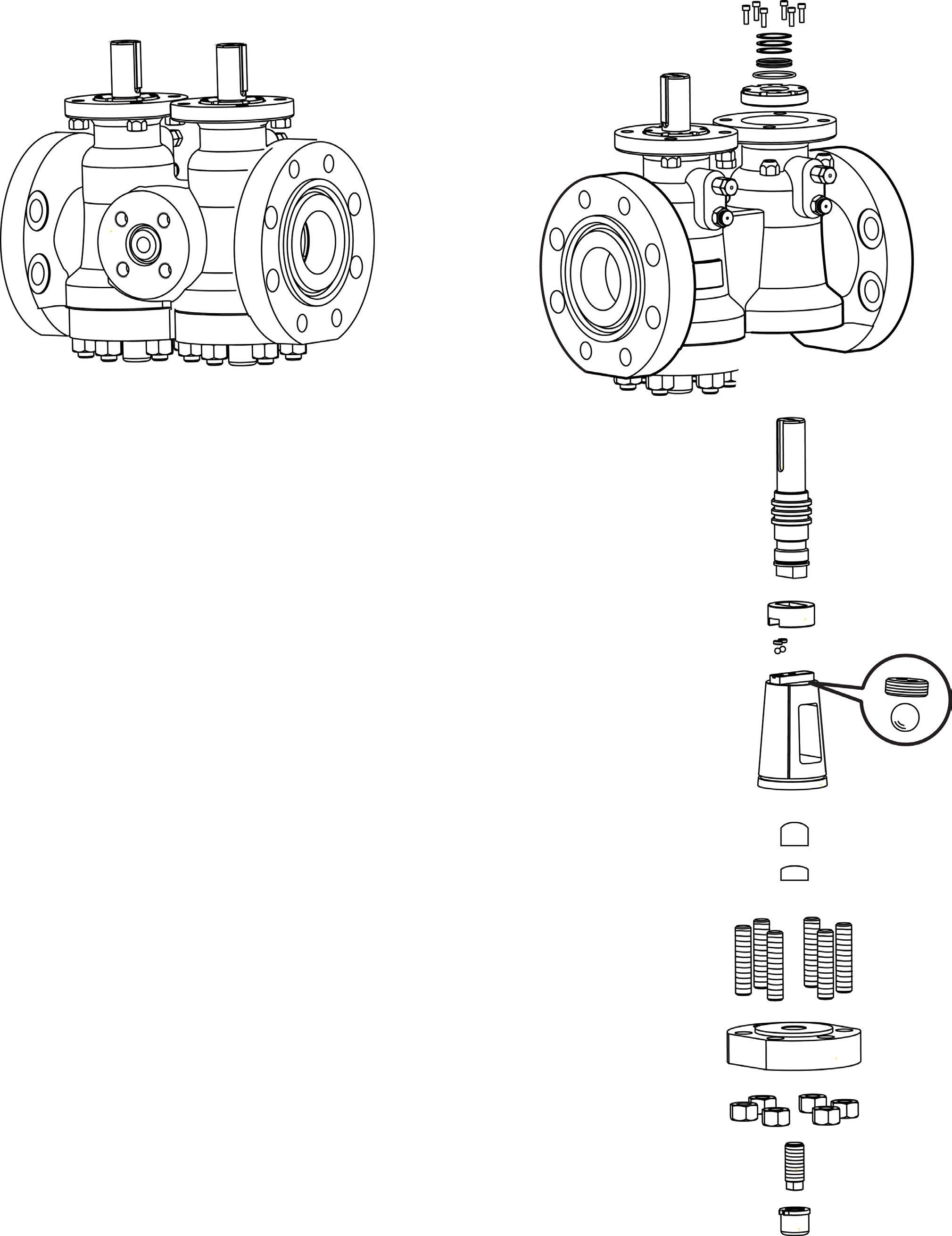
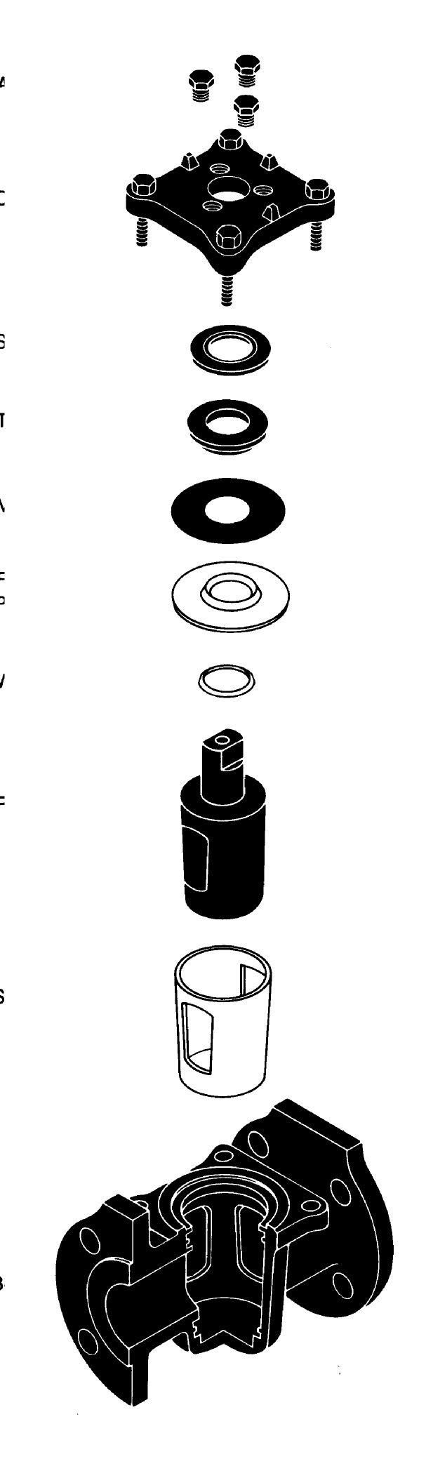
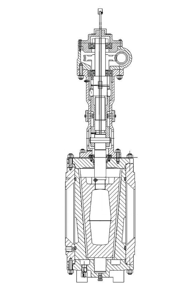
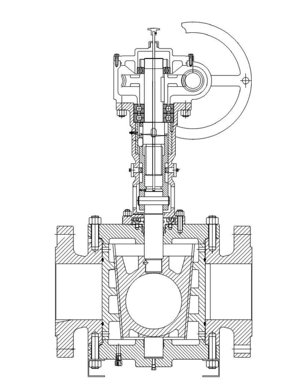
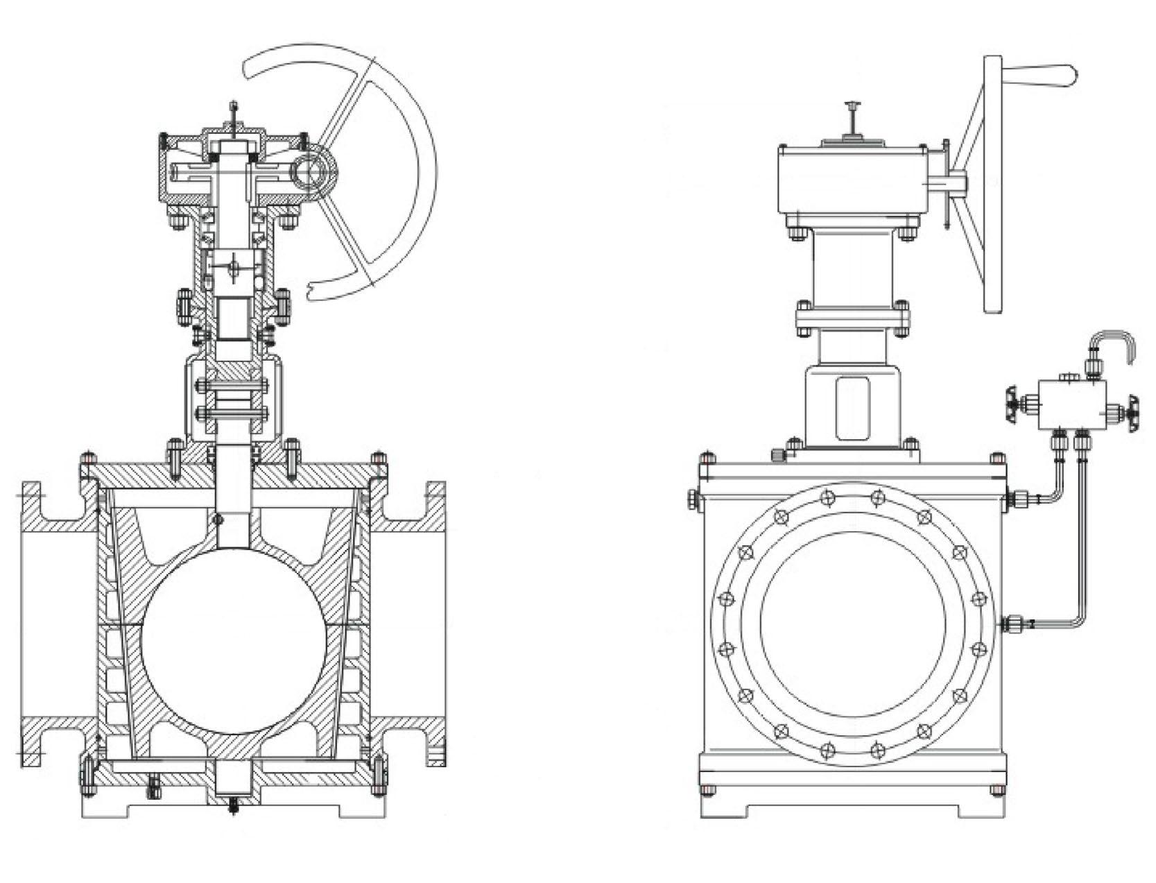
Exploded View - Typical* APV Pressure Balanced Plug Valve
Body 2. Plug - Metal-to-metal seating. Hardened & Nitrided c/w pressure balance holes
3. Blow Out Proof Stem - Electroless Nickel Plated 4. Thrust Support Pad/ Bearing 5. Retainer Thrust Support Seat
Plug Loading Screw
Spiral Wound Gasket 8. Upper Diaphragm Plate
Lower Diaphragm Plate
Bolted Lower Cover Flange
Equaliser Ring - for low torque and bubble tight sealing
Centering Support Ball Head
Thrust Seal
Top Retaining Gland Flange 15. Graphite ‘Fire Safe’ Stem Seals 16. Stem O-rings 17. Studs 18. Heavy Hex Nuts
19. Socket Head Cap Screws 20/23. Pressure Balanced hole c/w ball check and retainer spring - anti static 21/22. Seat & Body Area Sealant Injector (c/w in-built check valve): renews sealing to downstream. Stem Sealant Fitting for emergency use only 26. Hex Heavy Nuts
Cap
*Typical example only, (Style A1 shown) refer to as-built drawing. Design varies according to size class & customer preference.
*Typical example only, refer to as-built drawing. Design varies according to size class & customer preference.
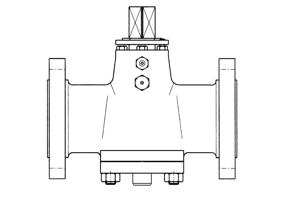
Pressure balanced, inverted plug
Valve designed to API 6D & API 599
Valve tested to API 6D or API 598
Face to Face to API 6D & ANSI B16.10
Flanged ends to ANSI B16.5
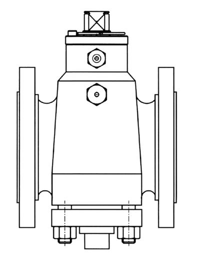
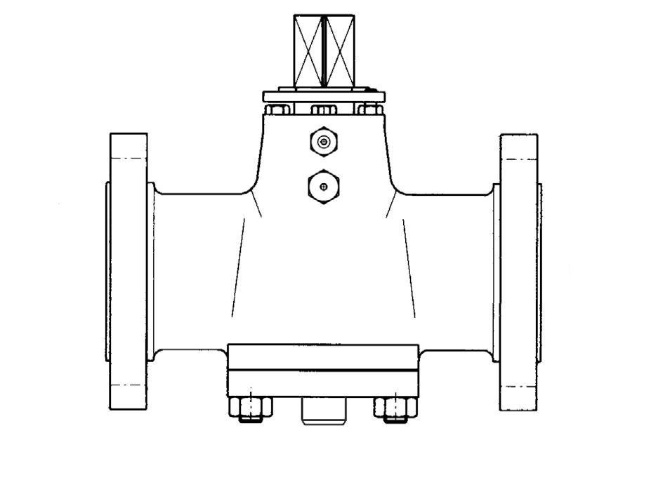
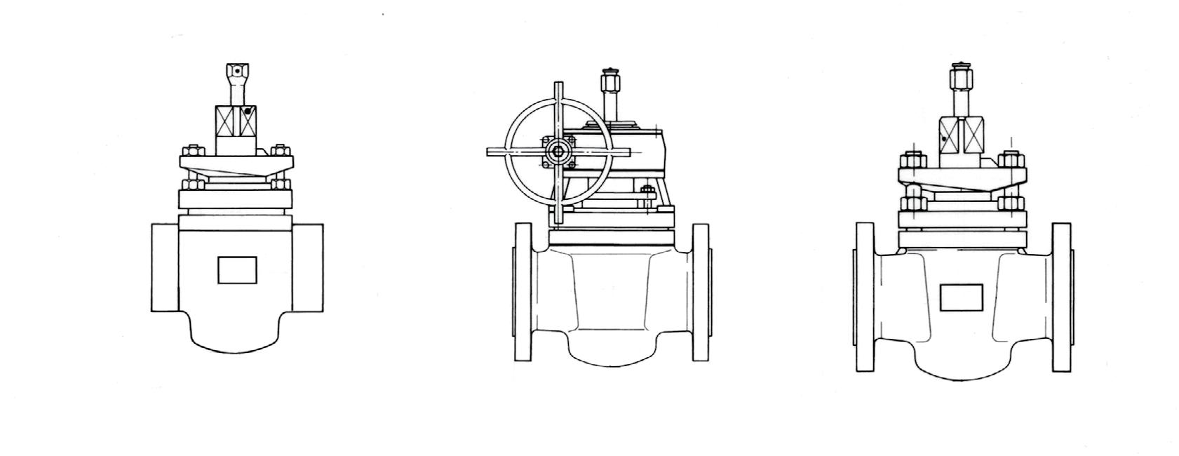
Short Pattern Class 150
Wrench Operated
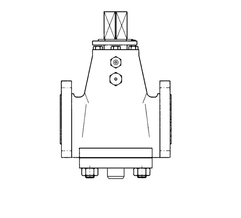
Refer to as-built drawing for specific detail.
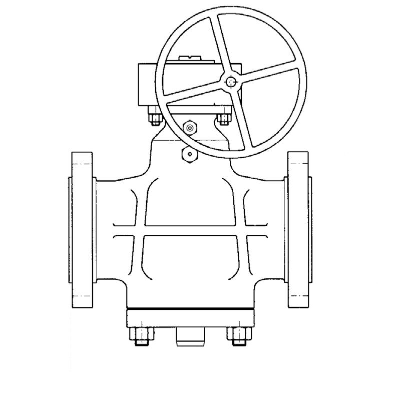
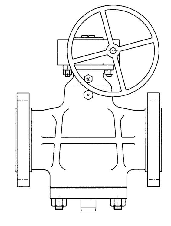
Short Pattern Class 150
Gear Operated
Refer to as-built drawing for specific detail.
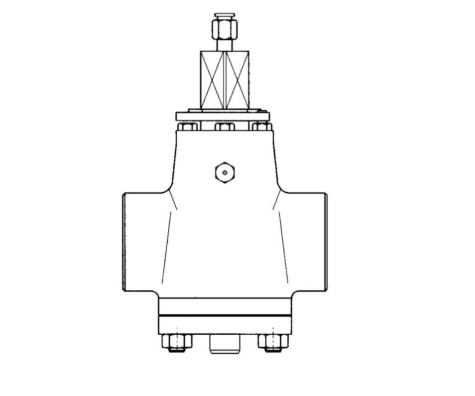
PRESSURE BALANCED LUBRICATED PLUG VALVES
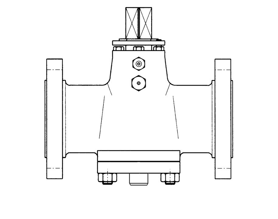
Pressure balanced, inverted plug
Valve designed to API 6D & API 599
Valve tested to API 6D or API 598
Face to Face to API 6D & ANSI B16.10
Flanged ends to ANSI B16.5
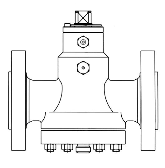
Regular Pattern Class 150
Wrench Operated
Refer to as-built drawing for specific detail.
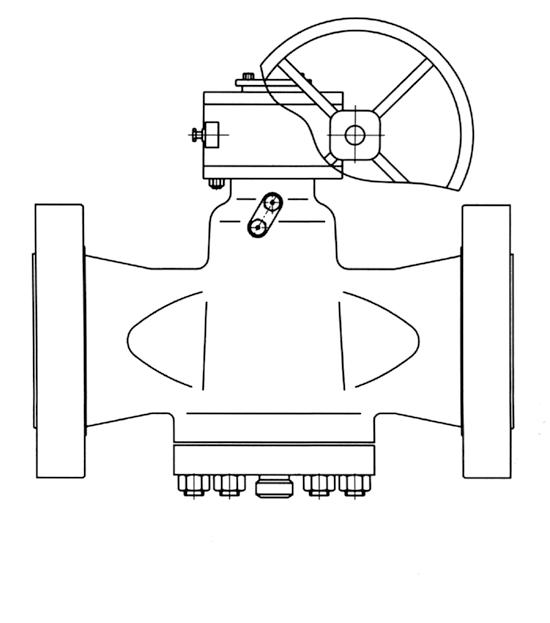
Regular Pattern Class 150
Gear Operated
Refer to as-built drawing for specific detail.
Pressure balanced, inverted plug
Valve designed to API 6D & API 599
Valve tested to API 6D or API 598
Face to Face to API 6D & ANSI B16.10
Flanged ends to ANSI B16.5
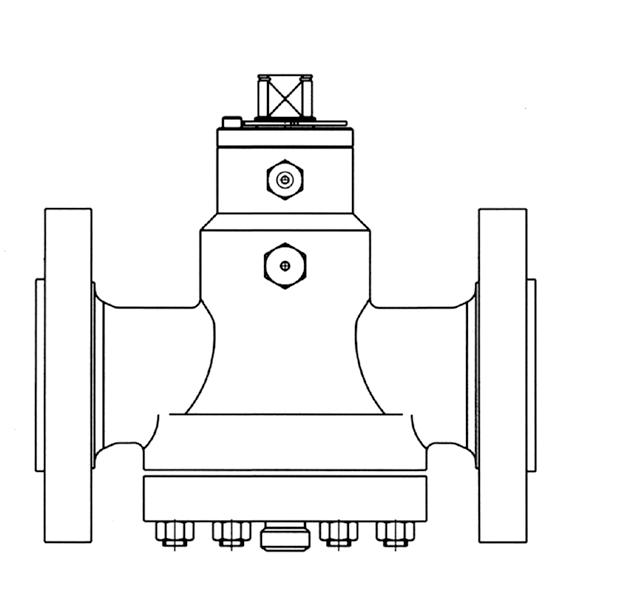
Venturi Pattern Class 150
Gear Operated
Refer to as-built drawing for specific detail.
Venturi Pattern Class 150
Gear Operated
Refer to as-built drawing for specific detail.
Pressure balanced, inverted plug
Valve designed to API 6D & API 599
Valve tested to API 6D or API 598
Face to Face to ASME B16.10 & API 6D
Flanged ends to ASME B16.5
Short Pattern Class 300 Wrench Operated**
* 159mm is short pattern, 165mm is 300lb ball valve and 250lb plug valve face to face. Refer to as-built drawing for specific detail. ** Gear operated 150NB & over
Regular Pattern Class 300 Gear Operated
Refer to as-built drawing for specific detail.
Pressure balanced, inverted plug
Valve designed to API 6D & API 599
Valve tested to API 6D or API 598
Face to Face to API 6D & ANSI B16.10
Flanged ends to ANSI B16.5
Venturi Pattern Class 300
Gear Operated
650 to 900NB (26” to 36”) refer to Drawing.
* API 6D Short Pattern
† Venturi Port, API 6D Regular Pattern face to face. Refer to as-built drawing for specific detail.
Pressure balanced, inverted plug
Valve designed to API 6D & API 599
Valve tested to API 6D or API 598
Face to Face to API 6D & ANSI B16.10
Flanged ends to ANSI B16.5 Regular Pattern Class 600 Wrench Operated
Refer to as-built drawing for specific detail.
R
& Venturi Pattern Class 600
Pressure balanced, inverted plug
Valve designed to API 6D & API 599
Valve tested to API 6D or API 598
Face to Face to API 6D & ANSI B16.10
Screwed ends to ANSI B 1.20.1
Screwed or Socket Weld Ends Class 600 Wrench Operated
Threaded Socket Weld
Screwed or Socket Weld Ends Class 800 Wrench Operated
Threaded Socket Weld
Pressure balanced, inverted plug
Valve designed to API 6D & API 599
Valve tested to API 6D or API 598
Face to Face to API 6D & ANSI B16.10
Flanged ends to ANSI B16.5
Refer to as-built drawing for specific detail.
Refer to as-built drawing for specific detail.
Pressure balanced, inverted plug
Valve designed to API 6D & API 599
Valve tested to API 6D or API 598
Face to Face to API 6D & ANSI B16.10
Flanged ends to ANSI B16.5
Regular Pattern Class 1500
Wrench Operated
Refer to as-built drawing for specific detail.
Regular and Venturi Pattern Class 1500
Gear Operated
Refer to as-built drawing for specific detail.
Pressure balanced, inverted plug
Valve designed to API 6D & API 599
Valve tested to API 6D or API 598
Face to Face to API 6D & ANSI B16.10
Screwed ends to ANSI B 1.20.1
Screwed or Socket Weld Ends Class 1500
Wrench Operated
Socket Weld
Screwed or Socket Weld Ends Class 2500
Wrench Operated
Threaded Socket Weld
Pressure balanced, inverted plug
Valve designed to API 6D & API 599
Valve tested to API 6D or API 598
Face to Face to API 6D & ANSI B16.10
Flanged ends to ANSI B16.5
Regular Pattern Class 2500 Wrench Operated
Refer to as-built drawing for specific detail.
Regular Pattern Class 2500
Gear Operated
Refer to as-built drawing for specific detail.

Valve designed to API 6A
Valve tested to API 6A
Dimensions to API 6A
PSI
PSI
PSI
• APV SSCR-DBB double block and bleed twin seal pressure balanced plug valves are perfectly designed for the most demanding service conditions & manufactured according to API 6D.
• This compact design within the standard API 6D end to end dimensions offers both space and weight saving.
• The taper plug is pressure balanced, metal to metal seating with lubrication as a secondary back up seal.
• The double plug internals offer a double block and bleed feature which is intrinsically fire safe.
• End connections are offered in line with the customers requirements and can be flanged, weld ends or clamp ends.
• All material types are available as per the specifications requirements.
• The stem is anti blow-out design with quarter turn manoeuvrability and low operating torque. The valve can be installed in any position.
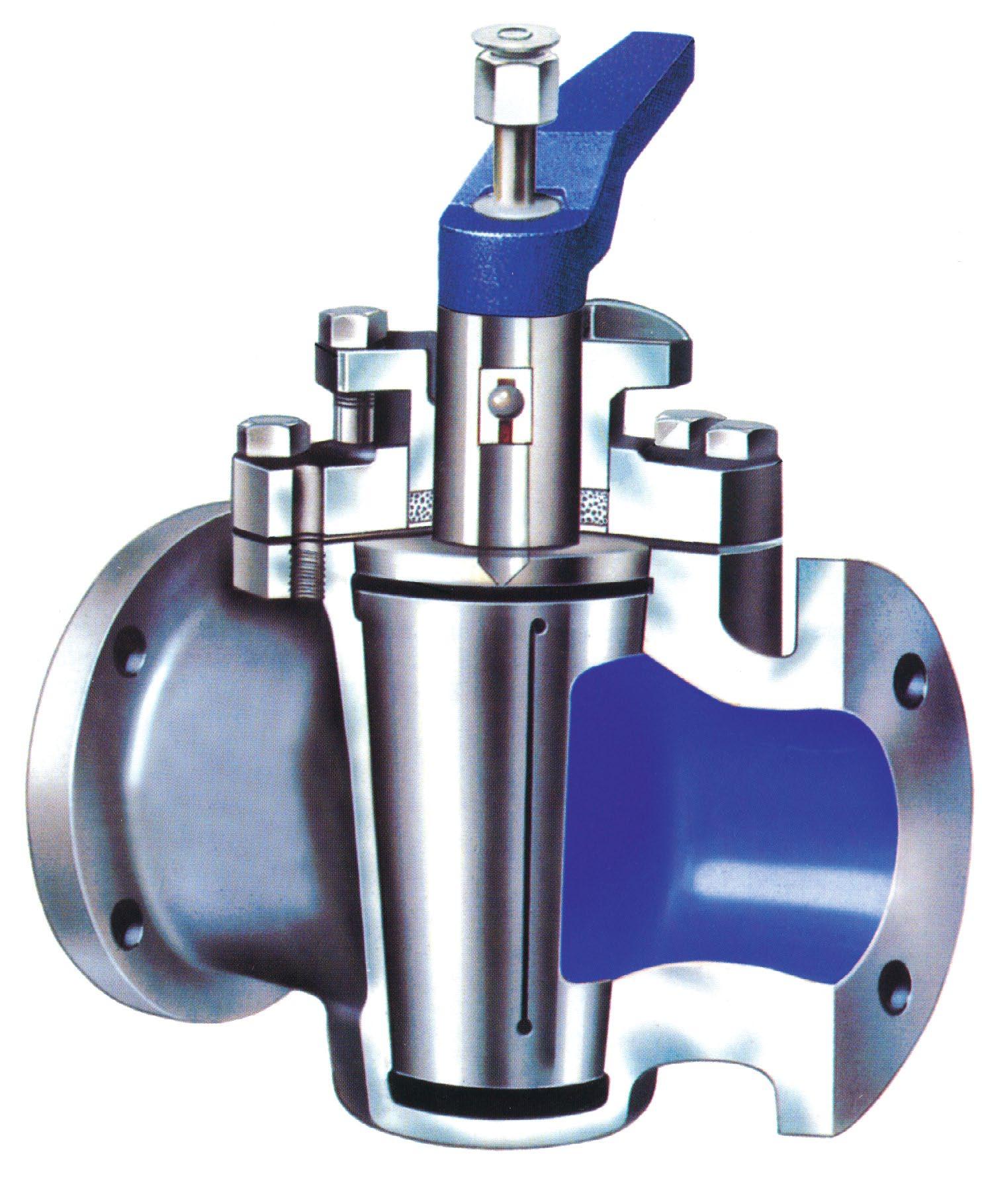
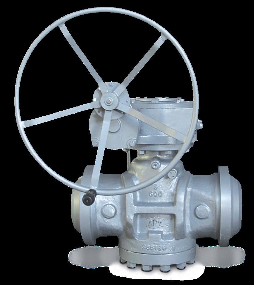
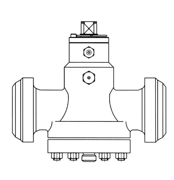
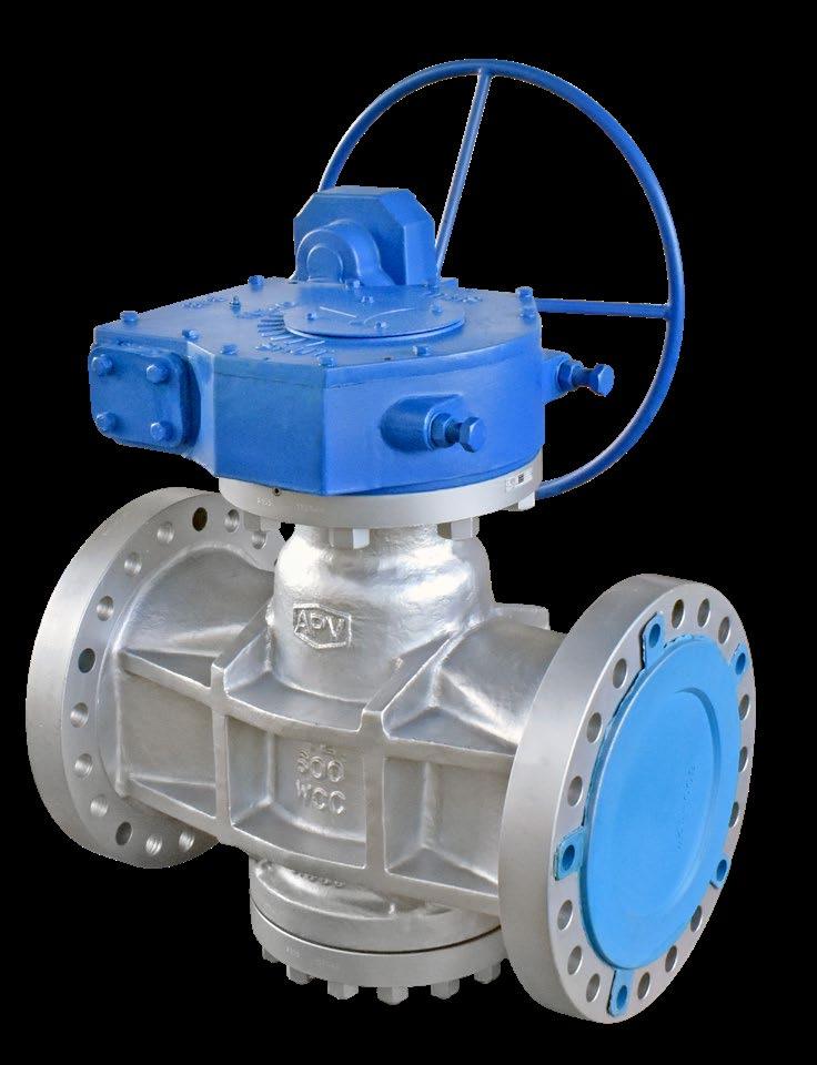
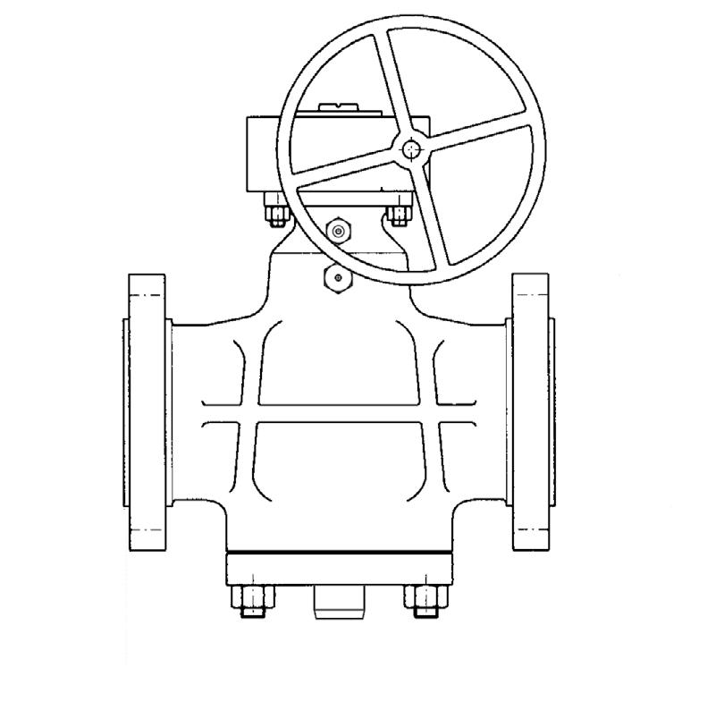
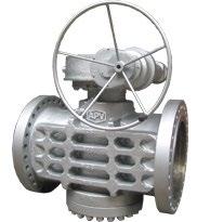
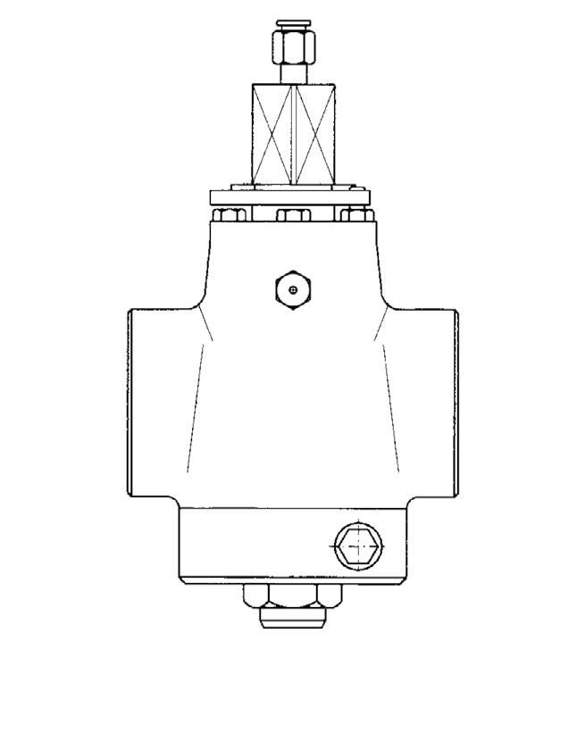
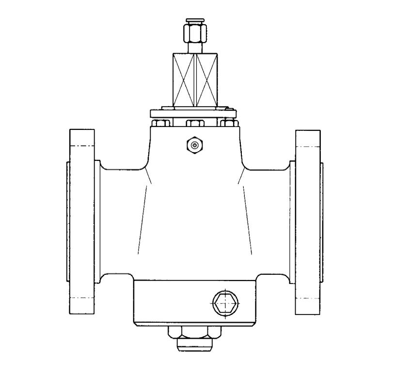
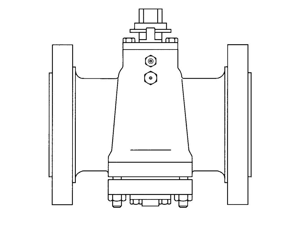
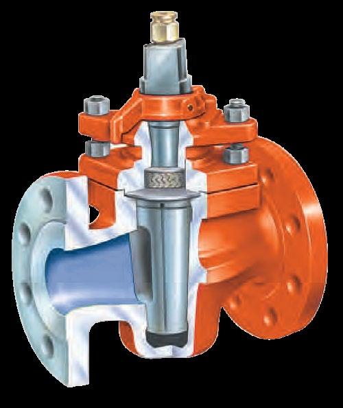
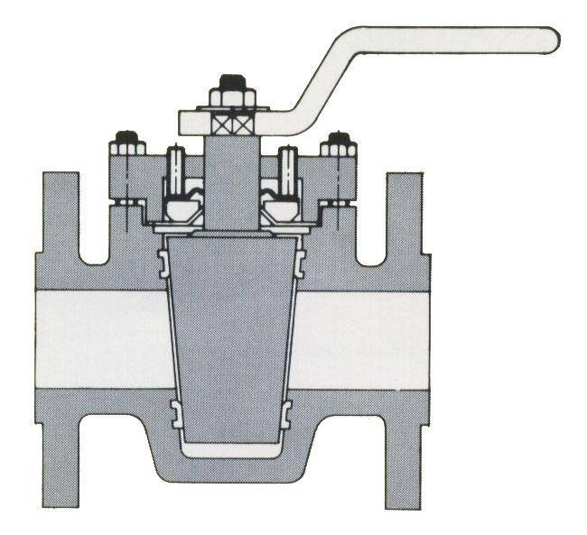
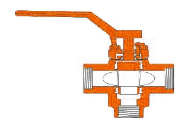
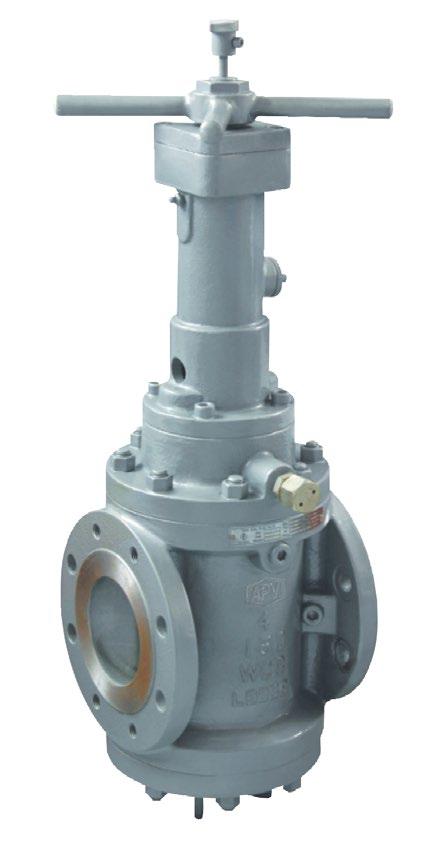
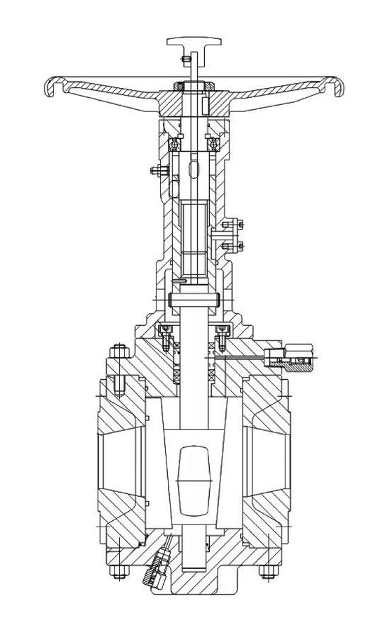
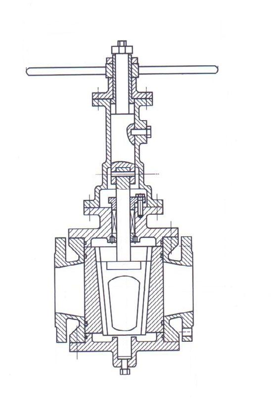
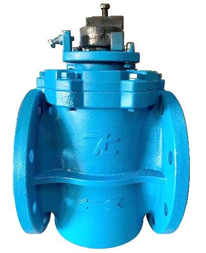
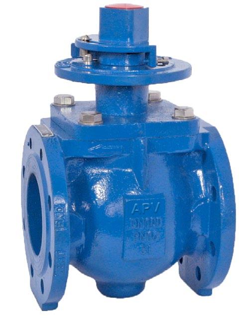
The standard style plug valve has the stem extended from the top of the valve.
The valves have a bolted cover which retains the plug in case the gland is removed. The gland maintains the pressure in the cover and prevents any leakage through the stem as well as retaining the plug in position.The gland supports the packing and acts as an anti-friction bearing to prevent stem packing rotation. Plug lubrication grease is injected through a nipple (fitted with a check valve). Greasing can be done when the valve is under pressure. The plug grooves avoid grease leakage into the line as during rotation each groove is isolated from the other grooves.
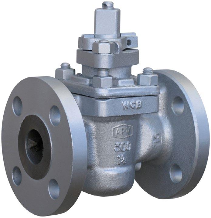
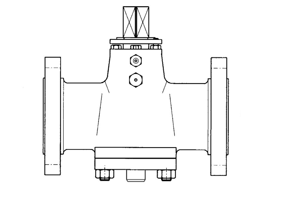
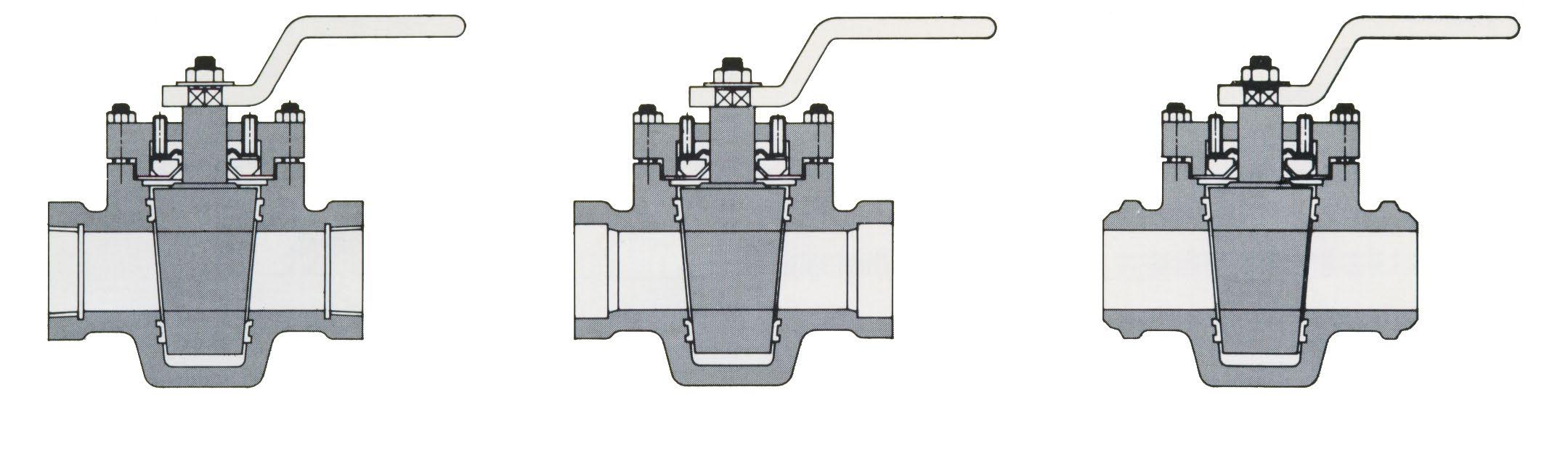
DIMENSIONS REGULAR PATTERN PLUG VALVES STANDARD TYPE
ANSI 150 SCREWED OR SOCKET ENDS WRENCH OPERATED
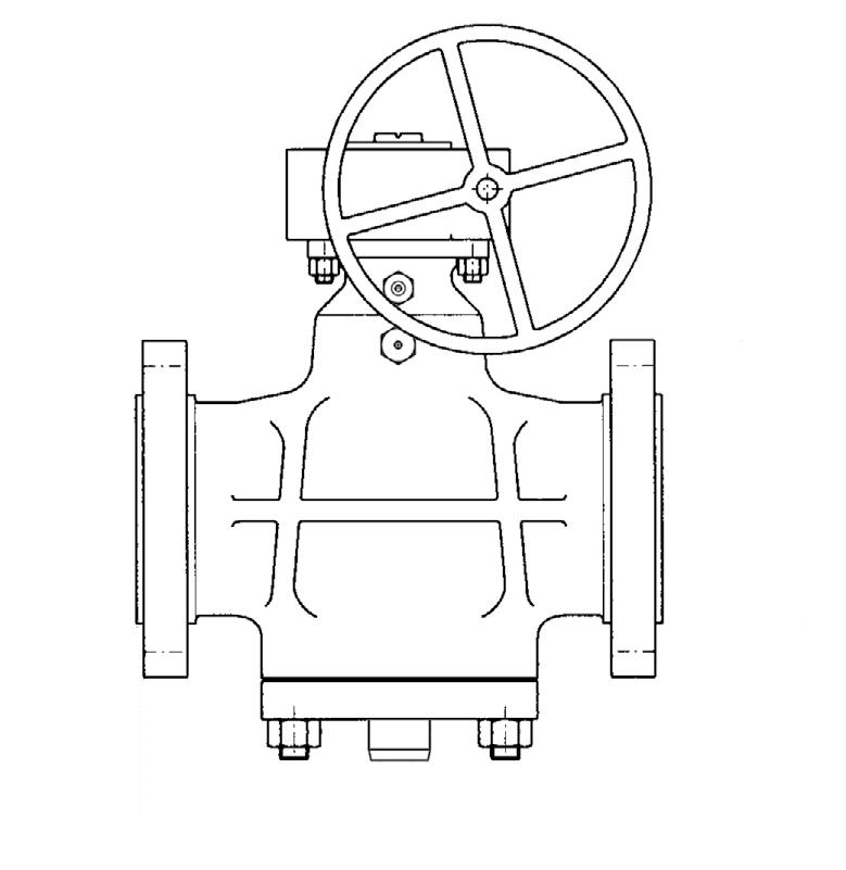
REGULAR PATTERN ANSI 150* & 125* WRENCH OPERATED
REGULAR PATTERN ANSI 150 & 125* GEAR OPERATED
* AS/BS Table D, E, F also available
SHORT PATTERN ANSI 150 & 125 GEAR OPERATED
350NB to 400NB refer to drawing. (Venturi pattern)
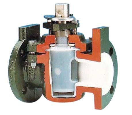
APV’s sleeved plug valves feature state-of-the-art in PTFE fluorocarbon seat design. With the structure of double sealing grooves with sealing rings, the high integrity bubble tight seal is provided both inline and to atmosphere. The sleeved plug valve, with working pressure ranges between -29°C to 180°C (-20°F and 356°F), are suitable for use in various kinds of pipeline application such as petrochemical, chemistry, pharmacy and chemical fertiliser.
Sleeved Plug Valves are designed for high standard of performance. These tight shut-off, bi-directional valves with cavity-free passage can be used on high pressure and vacuum services. APSL valves ensure long-term reliable operations with simplified in-line maintenance.
Size & Rating for Flanged End: 15NB ~ 300NB (1/2” - 12”) - Class 150, 300, PN10, PN16 350 ~ 400NB (14” - 16”) - Class 150
Size & Rating for
End Connection Flanged, Screwed, Butt Weld & Socket Weld. Design Std.
to Face (for
Refer to drawing for all dimensions
• Raised face dimensions for class-150 and class-300 as per ANSI B-16.5
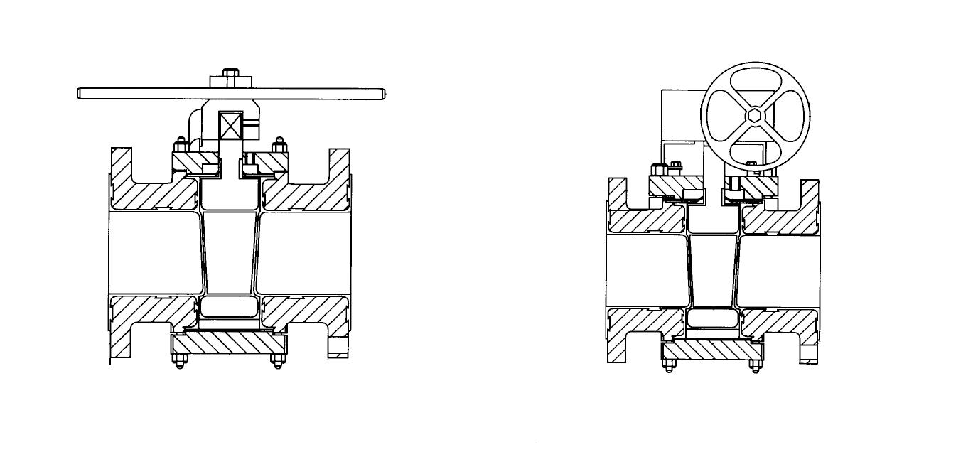
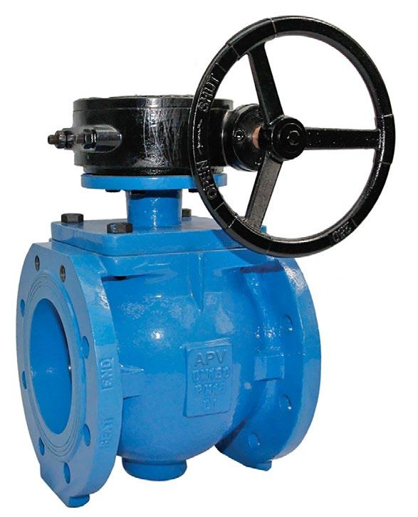
• Valve up to size 100mm are lever operated.
• Valve size 150mm and above are supplied with Gear operator.
• AS/BS Table D, E, F, H also available.
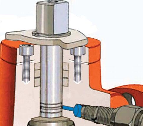
Adjusting bolts (4)
Bonnet (5) & Bolts (6)
Static eliminator (7)
Thrust collar (8)
Metal diaphragm (9)
PTFE diaphragm (10)
Seal ring (11)
Plug (2)
Sleeve (3)
Body (1)
Sleeve (3) PTFE PTFE PTFE PTFE
Adjusting bolts (4)
Cover (5)
Cover bolts (6)
Static eliminator (7)
Thrust collar (8)
Metal diaphragm (9)
Formed diaphragm (10) PTFE PTFE PTFE PTFE
Wedge ring (11)
Gland Flange (12) 304SS
Bonnet Gasket (13) PTFE PTFE PTFE
Indicative only, refer as built drawing.
Available body & trim materials
Carbon Steel Alloy 20
Ductile Iron Hastelloy B
Duplex Body (1) & plug (2)
Hastelloy C
Nickel
Monel
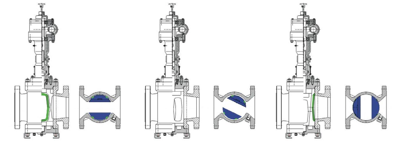
Flow Configurations
Only position 90° in plugs Type A & Type B will provide a complete shutoff condition.
90 degree turn is standard, 180 degree turn is optional.
3/4”
*Gear Operated
1
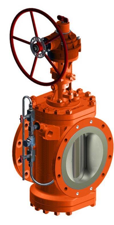
APV’s lined plug valves feature state-of-the-art in PTFE fluorocarbon lining design. With the structure of double sealing grooves with sealing rings, the high integrity bubble tight seal is provided both inline and to atmosphere. The lined plug valve, with working pressure ranges between -29°C and 180°C (-20°F to 356°F), are suitable for use in various kinds of pipeline application such as petrochemical, chemistry, pharmacy and chemical fertilizer.
• Bi-directional flow
Bi-directional inline bubble-tight seal is independent of line pressure, hence more convenient for valve installation and usage.
• Fluorocarbon seat design
The PTFE sleeve retained by the special 360° metal lips around the ports.
• No body cavities
There is no cavity in the plug valve for accumulating the medium.
Maximum corrosion resistance and eliminates product contamination. Complete PTFE lining in the body and on the flange faces with PFA covered plug and PFA reverse lip diaphragm-type stem seal. Features include: self-adjusting stem seal; non lubricated; positive shutoff; in-line adjustment.
(ANSI Class 150) rated at 180 psi (1,240 kPa) @ 400°F, 285 psi (1963kPa) @ 100°F
(ANSI Class 300) rated at 300 psi (2,206 kPa) @ 400°F; 750psi (5,102 kPa) @ 100°F.
DIMENSIONS (INCHES)
8” to 12” refer to drawing.
DIMENSIONS (MM)
200NB to 300NB refer to drawing.
LEGEND
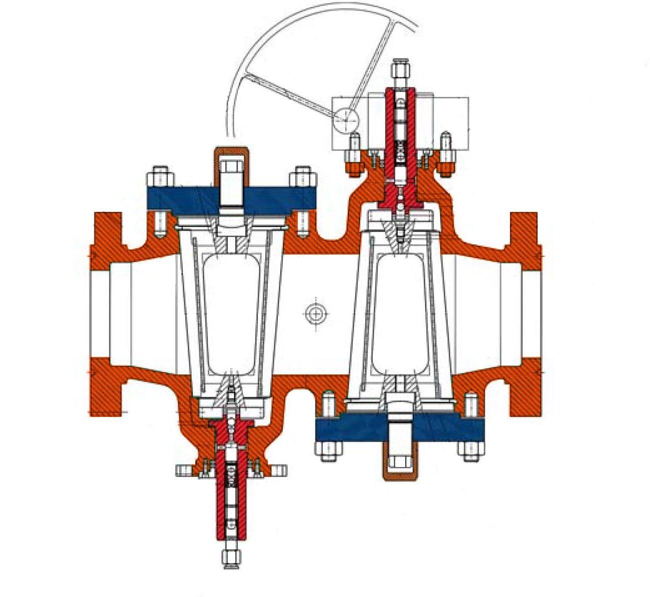
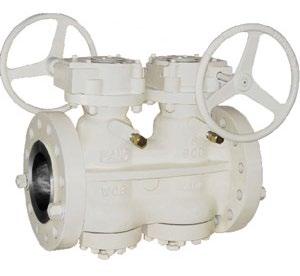
DOUBLE BLOCK AND BLEED SOLUTIONS
• Permanent integral thermal relief and bleed function
• In-line mainternance in case of seal replacement
• Very short installation space required
• Double isolation function, according API-6D/ISO 14313
• Only 1 actuator required to operate the valve
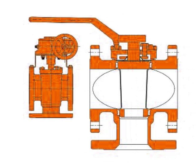
Unlike other valve types, the APV TWIN Dual Expanding Twinseal style plug valve creates an optimum seal without causing any abrasion and wear, providing a ‘zero-leakage’ solution, upstream and downstream ensuring a long life-time of the seals and valve, as well as a low opening and closing torque. This unique design is combined with a bleed function, all in one valve, saving space as well as providing a reliable, safe and economical solution.
PRODUCT STRUCTURAL FEATURES
Used in various industries such as petroleum, chemical industry, chemical fertiliser, power industry etc. Class 150 - 1500LBS and working temperature of -29~180°C.
MAIN STRUCTURAL FEATURES
• The Twinseal style double expanding plug valve has a rugged structure, reliable sealing, excellent performance and exact tolerances.
• Sealing rings around the valve plug provide the seal. It has a unique design incorporating machined and pressed sealing rings.
• Bi-directional, double block and bleed.
OPERATION PRINCIPLE
When the hand wheel is turned, the plug will rotate toward the closing direction for 90 degree turn closing, the plug will then be firmly seated after moving downward into its closing position.
When the hand wheel is turned inversely, first of all the plug will move upward and the valve plug and valve seat will be separated till the valve plug is turned 90 degree driven by the plug and finally the bore of the plug will be in alignment with the channel of valve body.
The advantage of this type of valve is during the opening and closing of the valve, the plug and valve seat are separated and there is no friction, thus the sealing face experiences no abrasion in the process, at the same time the soft seal is applied for sealing so that there will be no leakage in the process of closing.
PERFORMANCE SPECIFICATION
* High / low temperature available up to 2500 Class.
Non-slam
The operator is self locking so that line pressure cannot force the plug to rotate. This prevents slamming and risk of injury.
Tight shut off
When the valve is closed, the seating segments are wedged tightly between the plug & body metal to metal. The soft seat material is compressed into the recessed groove. The design does not require springs or pressure to effect a seal.
Double block and bleed and zero leakage
The Twinseal valve provides upstream and downstream seal in both directions and a bleed point is then provided between the two seats, to prove no leakage.
The Twinseal meets the demands of frequent cycling & verifiable, reliable zero leakage with positive shut-off upstream & downstream. Zero wear
Twinseal valves provide positive shut-off with zero leakage. The design of the valve ensures that during opening & closing the seals are not in contact with the body. Only at the last stage of closing does the seal contact the body - and then the force is compression only. Every turn of the handwheel retracts the seals from the body. That means no wear to the seals & long life.
Large port
Twinseal valves have a nominal plug port of 60 - 70% thus effecting minimum pressure drop. True circular full port also available.
No. Part Name Material 1 Body ASTM A216 - WCB, ASTM A351 - CF8, CF8M, CF3, CF3M 2
Bonnet
A216 - WCB, ASTM A105, ASTM A351 - CF8, CF8M, CF3, CF3M
PTFE, VITON
Gasket SW316 + Graphite
Gasket
Wound
Bolt ASTM A193 - B7, A320 - B8, A193 - B8M 8 Nut ASTM A194 - 2H, A194 - 9, A194 - 8M
Plug ASTM A216 WCC+ENP, ASTM A182 - Gr. F6a, ASTM A182 - F22, ASTM A351 - CF8, CF8M, CF3, CF3M
Disc
A182 - Gr. F6a, ASTM A182 - F22, ASTM A351
General guide refer as built drawings.
COMMON APPLICATIONS
Metering Stations
Dual Expanding API 6D Plug Valves are exceptional for critical applications where ‘zero-leakage’ is required. In highly critical applications such as Metering Stations even a small leak will cause an error in the calibration of the flow-meter, resulting in an incorrect flow measurement which can have a major financial impact.
Aviation & Marine Fueling Stations
Dual Expanding Plug Valves provide a ‘zero-leakage’ solution, making the valve highly suitable for fueling stations in the aviation and marine industries. They are used on the truck loading racks, as a tank shut off valve and on the Jetty loading and unloading docking stations.
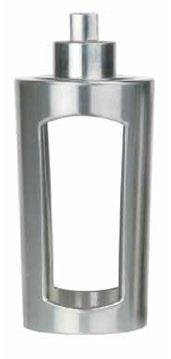
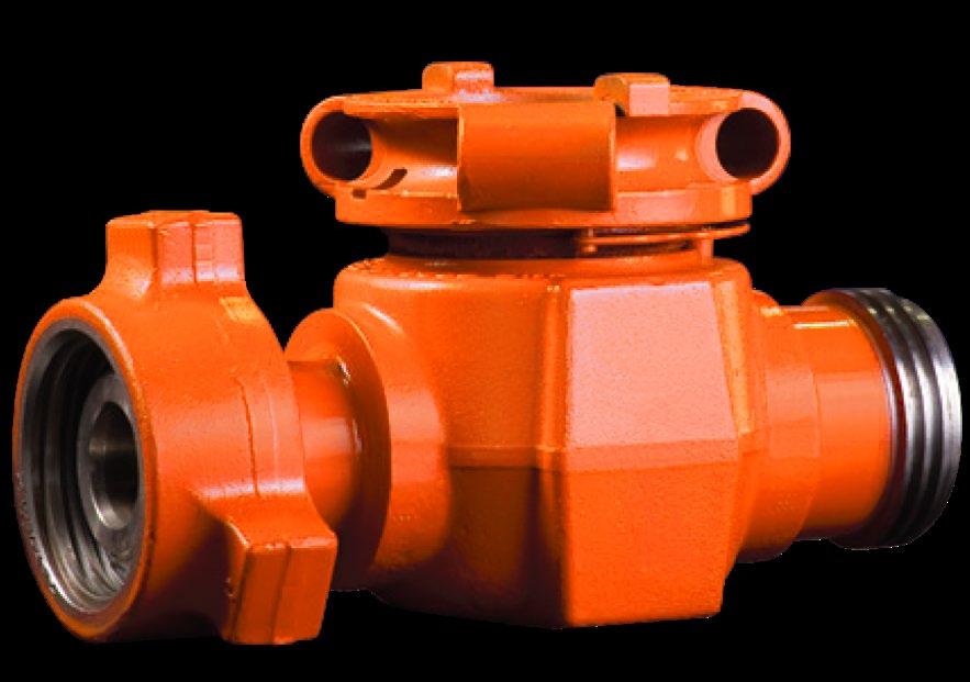
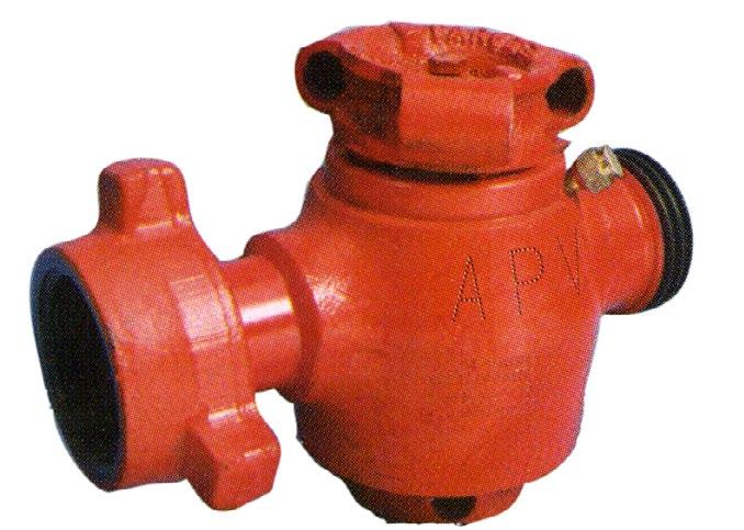
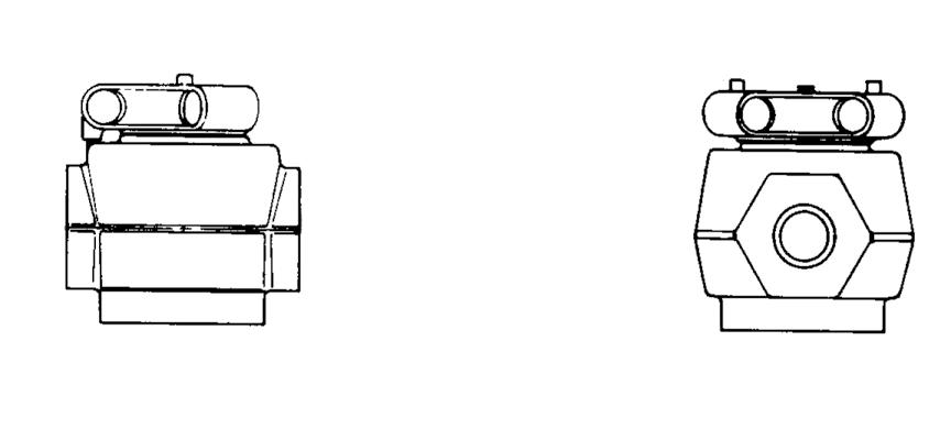
Quarter-turn valves for standard and sour gas services to 20,000 psi. Rugged plug valves 1 to 3 inches and with threaded or detachable Weco®™* style wing union ends. Used for cementing, fracturing, acidizing and other high-pressure lines which handle slurries, abrasives, drilling muds, chemicals and other similar products. These valves are equivalent to SPM®™* style. We also can also supply model MC-OD-PV which is equivalent to Lo-Torc®™* style (even parts interchange).
Floating segments ensure positive seal
Two seal segments which float slightly to offset possible micro-expansion of the valve body in extreme high-pressure applications and to ensure a positive seal at all times.
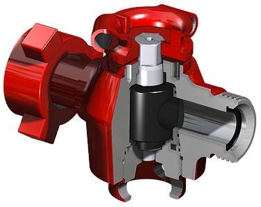
Easy operation under pressure
The plug valve’s cylindrical plug fits between a set of seal and side segments to prevent the plug from sticking to the valve body, permitting easy operation under pressure.
Visible indication of valve position
A visible, quarter-turn stop on the plug cap indicated clearly when the valve is fully open or fully closed. A detent spring holds the valve in the desired position.
In-line maintenance
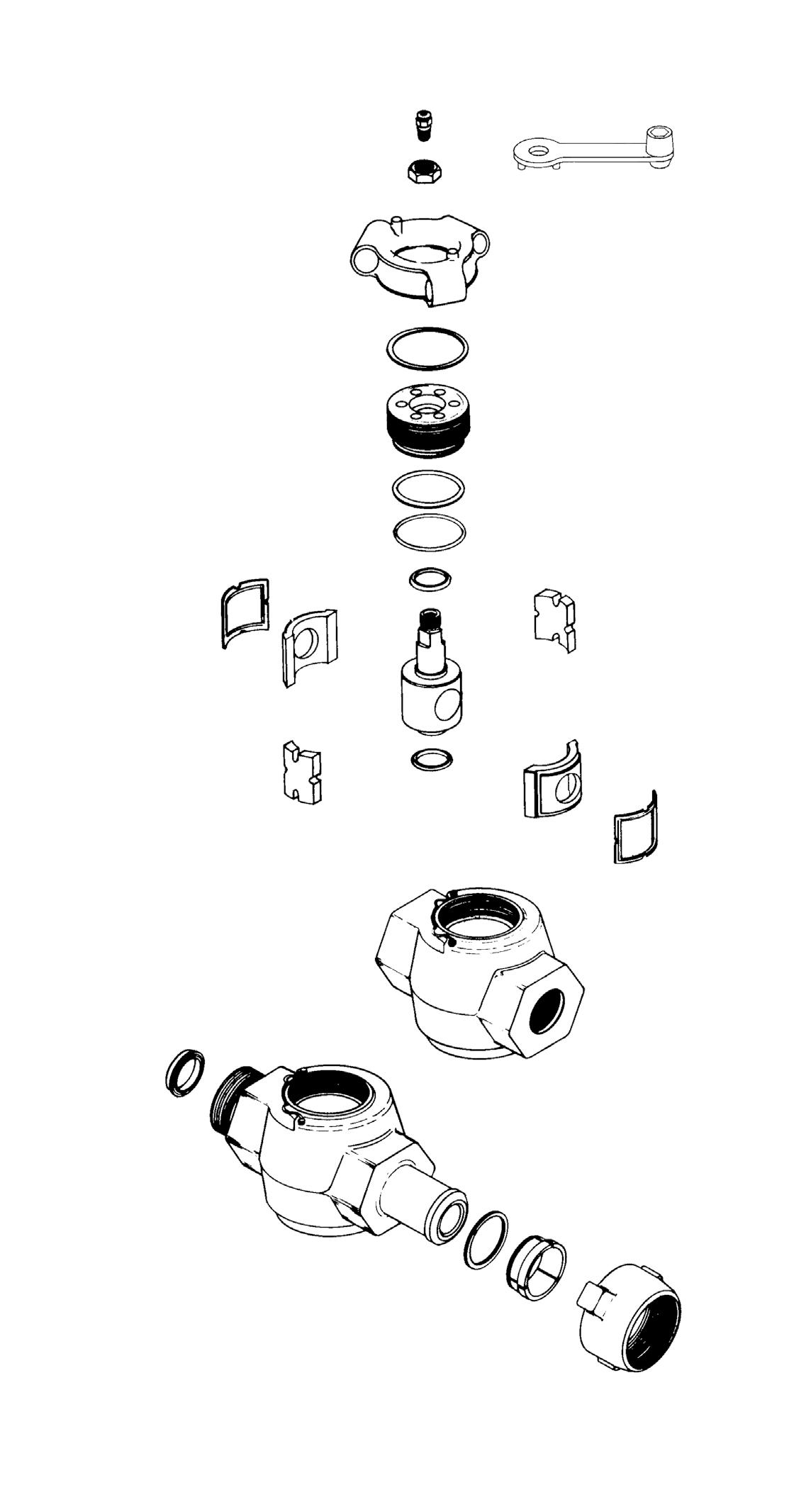
Can be rebuilt in-line by replacing the side and seal segments.
* FMC®™ & Weco®™ are registered trademarks of TechnipFMC. SPM®™ is a registered trademarks of The Weir Group. FMC®™, SPM®™ & Weco®™ are not related to APV or GSL in any way.
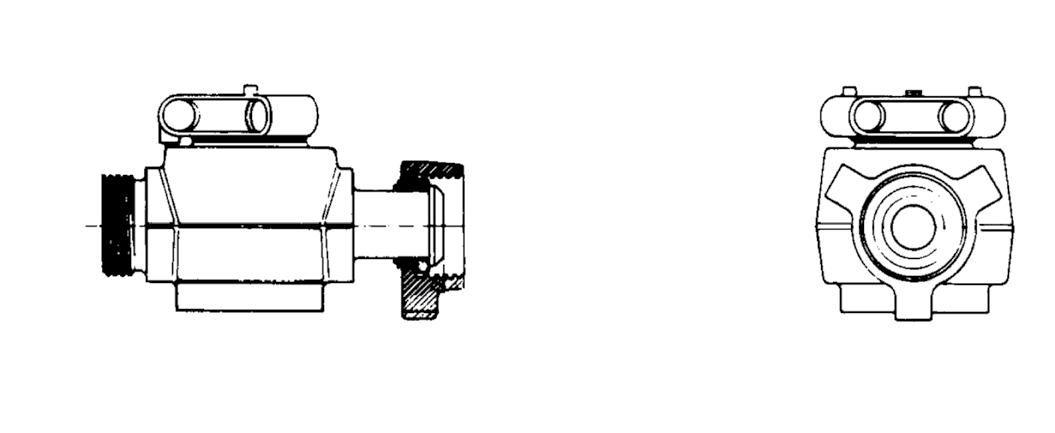
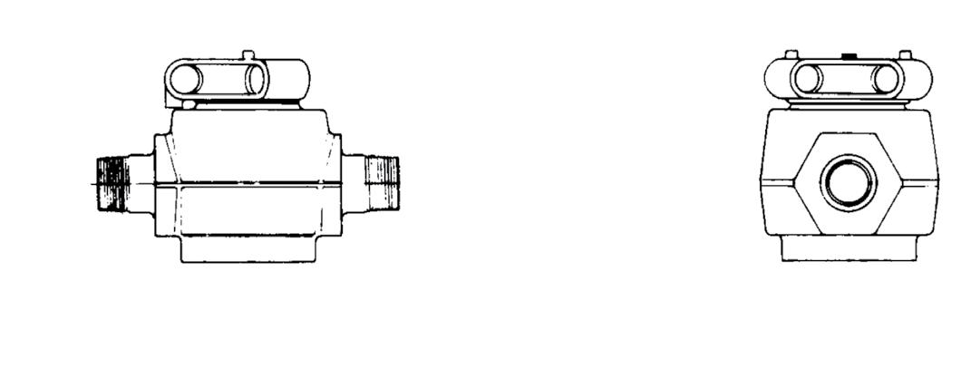
Quarter-turn valves for standard and sour gas services to 20,000 psi. Rugged plug valves 1 to 3 inches and with threaded or detachable Weco®™* style wing union ends. Used for cementing, fracturing, acidizing and other high-pressure lines which handle slurries, abrasives, drilling muds, chemicals and other similar products. These valves are equivalent to Lo-Torc®™* style.
Floating segments ensure positive seal
Two seal segments which float slightly to offset possible micro-expansion of the valve body in extreme high-pressure applications and to ensure a positive seal at all times.
Easy operation under pressure
The plug valve’s cylindrical plug fits between a set of seal and side segments to prevent the plug from sticking to the valve body, permitting easy operation under pressure.
Visible indication of valve position
A visible, quarter-turn stop on the plug cap indicated clearly when the valve is fully open or fully closed. A detent spring holds the valve in the desired position.
In-line maintenance
Can be rebuilt in-line by replacing the side and seal segments.


* Lo-Torc®™ is a registered trademark of Halliburton. Weco®™ is a registered trademark of TechnipFMC. Lo-Torc®™ and Weco®™ are not related to APV or GSL in any way.
DIMENSIONAL DETAILS
ECCENTRIC
Design and manufactured in accordance to AWWA C517.
The flow area provides effective throttling performance for water, waste water with solids, sludge and slurries. The flow area is no less than 80% of the pipe area.
Cast Iron or Ductile Iron body and cover, Ductile Iron disc coated with NBR/EPDM rubber, Nickel or 304SS welded seat.
Working pressure PN10~PN16, ANSI CLASS 125/150, Table D, E.
Temperature NBR -20°C~80°C, EPDM -20°C~120°C.
Flange standard ANSI B16.1, ANSI B16.5, AS 2129, AS 4087
Face to Face Dimensions conforms to AS 5752 (ISO 5752-3)
DIMENSIONS (MM)
MATERIALS
EPDM / NBR COATED
Seat SUS304 OVERLAY
Packing PTFE
Bearing SUS304
SSCR
SSCR-
DBB
body pressure balanced, inverted style, firesafe
SAPM Steel body, standard type, taper style, firesafe
APFP Steel body, full port, circular port, firesafe
SAPL Iron body, standard type, taper style
APBR Iron body, standard type, inverted style
APMM Multiway 3 way L port
APMN Multiway 3 way T port
APMW
APFL
APSL
APEC
Ni-hard treated plug G 316SS/CF8M
304SS/CF8 I CR13/F6/F6A/CA15 J PTFE/PFA/XYLAN bonded
CR13/F6/F6A + Ni Hard/ENP
Chrome Carbide Coated
Tungsten Carbide Coated
SG (nodular)
Metal seat non lubricated
resistance B=Satisfactory C=Poor D=Not recommended
This table is intended as a general guide only and does not imply guarantee of service performance. Final selection of material should be dictated by the specific environmental requirements. Factors such as:- temperature, valve type, pressure, flow conditions, other trim components, etc., can all have a significant effect on material selection hence this is only a rough guide. Australian Pipeline Valve recommends that customers’ engineers analyse service requirements and specify the materials they consider optimum for their service conditions.
This table is intended as a general guide only and does not imply guarantee of service performance. Final
requirements. Factors
a rough guide. Australian Pipeline Valve recommends that customers’ engineers analyse
conditions.
For a more detailed chemical resistance chart on valve body seat and seal material http://www.globalsupplyline.com.au

Australian Pipeline Valve are short lead time valve manufacturers. Tell your purchasing staff, engineers and plant managers about us
Australian Pipeline Valve don’t consider in our design the following factors of risk:
1. Australian Pipeline Valve ‘Standard’ plug valves can be used in a temperature range between -28.8/+250°C. For service temperatures below -28.8°C plug valve construction materials shall be submitted to an impact test at the minimum service temperature. For temperatures between -28.8°C & +250°C plug valves have to be provided with seals able to withstand the temperature degree required.
2. The onus is on the customer to specify all materials of construction and service conditions. Australian Pipeline Valve shall assume standard materials and conditions if not otherwise specified.
3. Australian Pipeline Valve ‘Standard’ plug valves are not designed with special devices to withstand a sudden thermal jump (thermal shock).
4. In general Australian Pipeline Valve ‘Standard’ plug valves are not mechanically designed to bear overloads due to exceptional atmospheric or natural phenomenon’s (such as earthquakes).
5. In general Australian Pipeline Valve ‘Standard’ plug valves are not designed to bear loads on flanges, on pipe connections or pipeline.
6. In general Australian Pipeline Valve ‘Standard’ plug valves can’t withstand ice inside their bodies (in this case user has to consider the optional stem extension for insulating, avoiding the presence of residual product inside the valve).
7. Australian Pipeline Valve ‘Standard’ non lubricated plug valves are suitable for ‘industrial’ oxygen (not medical) service when supplied degreased and packed in polyethylene bags only.
8. The compatibility between plug valves construction materials and medium is selected by the user. The user is ultimately responsible for verifying the compatibility between medium and materials.
9. Other special service applications like abrasive service, dirty service, high temperature service, low temperature service, vacuum service etc, need to be stated at quotation phase.
Before installing the plug valve onto the pipe-line it is mandatory for the user to verify the compatibility of the plug valve with service conditions (medium, temperature and pressure). With reference to standard plug valves held in stock, the reseller and end user will have to assure themselves of the compatibility with the use of conditions required by the customer. Australian Pipeline Valve plug valves must be only used for on-off (fully open/fully closed) service.
Before using the plug valve in a potential explosive atmosphere it’s necessary: -
• To verify the compatibility between the plug valve and the zone in which the valve should be installed.
• To foresee the pipe-line ground condition on which the plug valve should be installed.
• To check that the temperature of the plug valve surface is not higher than the flammable point of the atmosphere in which the plug valve is installed (in this case specify an insulating cover device for the valve and an extension for the wrench)
• Before installing plug valves with welding ends, make sure that the process of welding is carried out observing all the safety norms the classified zone requirements.
• To avoid mechanical knocks during the installation that may cause sparks.
Australian Pipeline Valve cannot be held responsible for damage caused by use of the product especially if it is improper use or modified.
“Australian Pipeline Valve produces isolation, control and flow reversal protection products for severe and critical service media in utility, steam, pipelines, oil & gas and process industries. APV valves and pipeline products form the most competitive portfolio in the market.”