SHORT VERSION
Click


Click
Bonnet gasket:
Blank Standard:- SS + GRP (BB), Pressure Seal Ring (PSB). N/A:- (WB). A SS + PTFE B S318 03 Spiral C PTFE D SS + PTFE + GRP E Ring Z Special
Stem packing: Blank Standard:- Graphite. N/A:- (Check Valves) F Fugitive Emission GRP I Fugitive Emission PTFE J Special L Live Loaded P Graphite + PTFE T PTFE
Denotes special suffix - Packing/Gasket
Operator: Blank Handwheel or N/A A Actuator C Counter-Weight D Dampner G Gear H Hammer Blow Handwheel L External Lever
End connection: Blank RF (B16.5) BA RF B16.47A (MSS SP44)
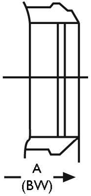
BB RF B16.47B (API 605) RJ RTJ BW Buttweld FF Flat Face SP is special drilling UD Undrilled UM Unmachined for RF/RJ
Bonnet: Blank Bolted C Cryogenic H Pillar & Bridge L Low Temperature Ext. P Pressure Seal S Bellows Sealed T Threaded W Welded
Body material: - see page 5. (WCB is Blank)
Denotes special suffix - Body/Bonnet/Ends/Operator
Blank Non NACE N NACE C Cryogenic
Blank Standard Configuration (Example Solid Wedge) A S Bend Globe D Globe-Stop Check
DG Globe - Stop Check Guided F Flexible Disc Gate J Slab Gate K Expanding Gate L Lever (Swing Check)
P Full Opening Swing Check (API 6D) Q Full Opening Piston Check (API 6D) R Right Angle S Parallel Slide Y Inclined Bonnet Z c/w Spring
Denotes trim - Code & Modifier (see below)
Basic identifier number denoting valve class and valve type (As shown in catalogue)
Prefix: Blank APV FZV APV-FZV J.V.
Valve Size
BODY MATERIAL CODE • BODY/BONNET MATERIALS
A890/A995-4A/CD3MN Duplex (F51)
A995-6A/CD3MWCuN
AL-Bronze
A995-5A/CE3MN
Duplex (F55)
B62/LG2/B148
Duplex (F53) 22 A296 M-35 Monel 23 A296 CW-12M Hastelloy C 24 A484 CU-5M CUC Inconel 825 25 A494 CY40 Inconel 600
A494 CW6MC Inconel 625
B367 GR.C2
Titanium (F2) 28 B367 GR.C3
Titanium (F3) 29 A358 LC4 Low Temp. 4-1/2% Nickel Steel 30 A358 LC9 9% Nickel Steel
31 A358 CA6NM 18-1/2% Chromium, Nickel-Molybdenum Steel
32 A217 WC4
33 A217 WC5
34 A217 WC11
35 A217 C12
36 A217 C12A
37 A217 CA15
0 SPECIAL
Nickel Chromium Molybdenum
Nickel Chromium Molybdenum
Chromium Molybdenum
Chromium Molybdenum
Chromium Molybdenum Vanadium
Chromium Steel
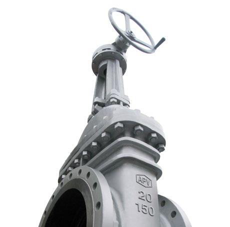
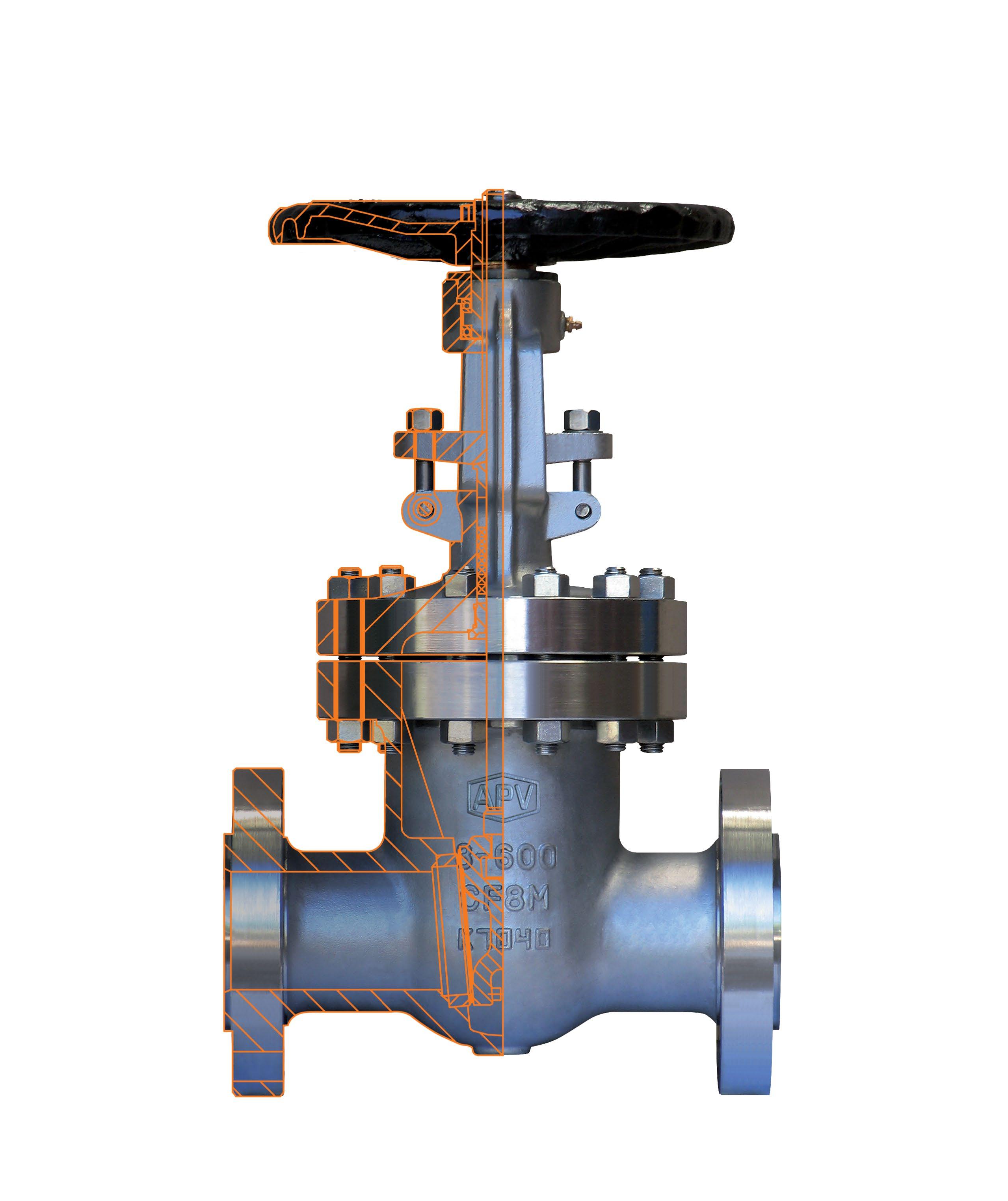
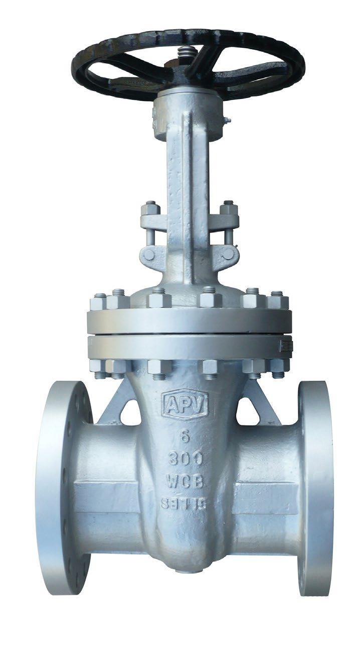
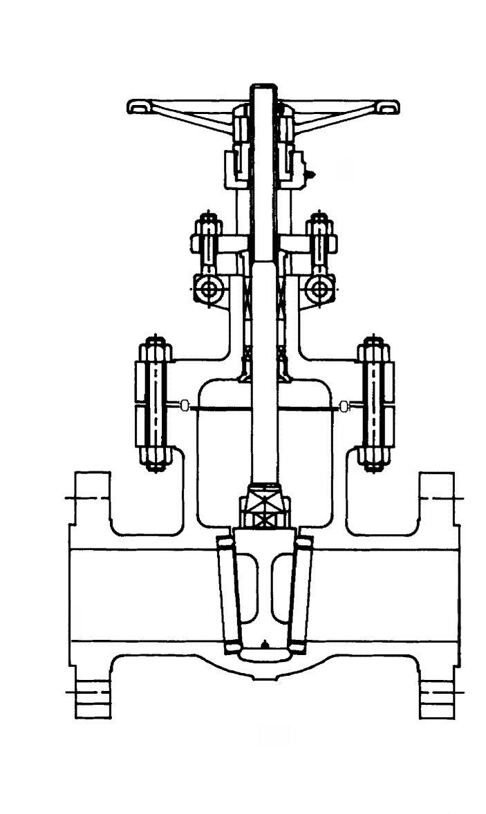
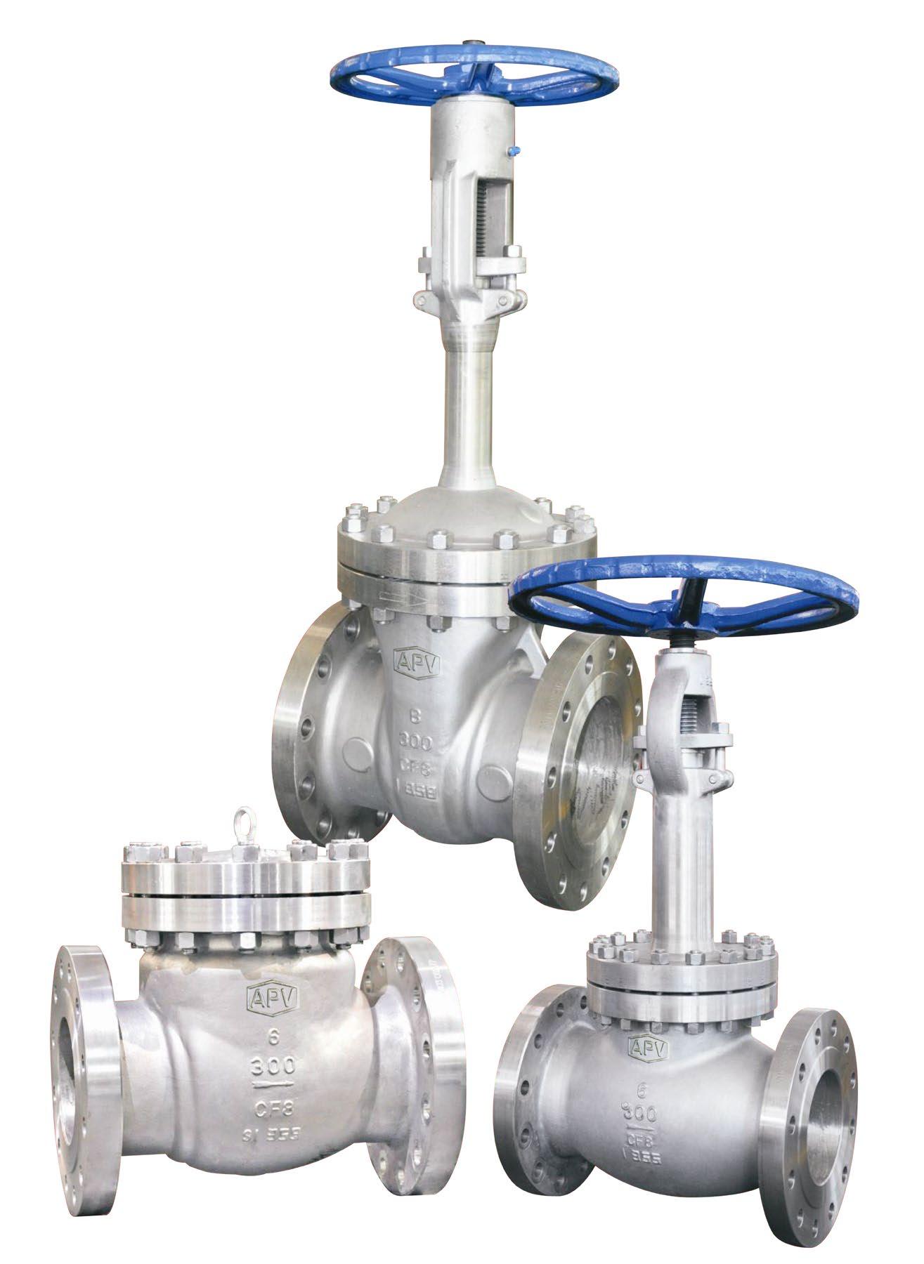
ANSI CLASS 150 ~ 2500
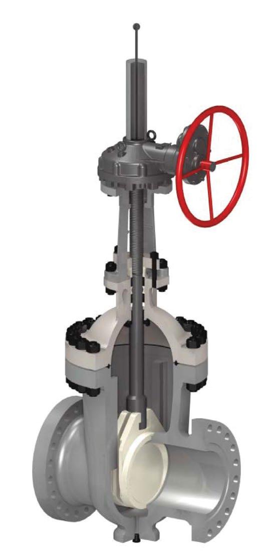
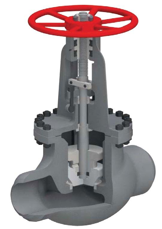
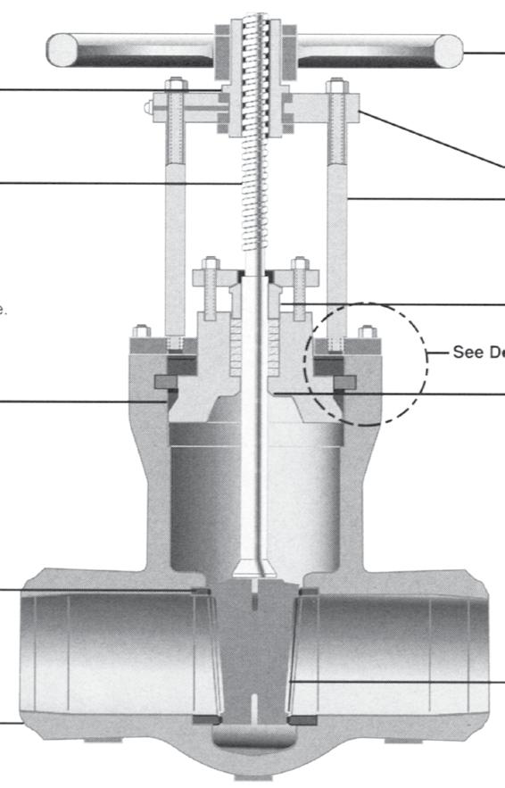
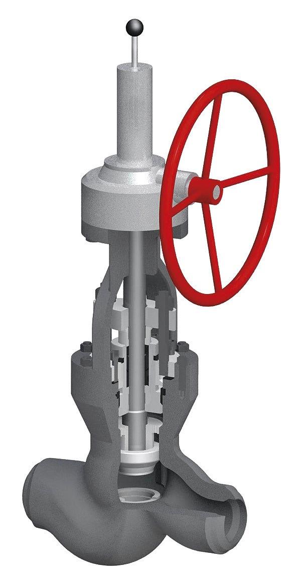
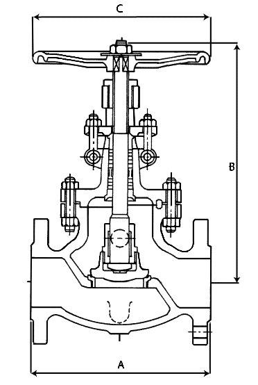
• Bolted bonnet, OS&Y, Flexible wedge.
• On smaller size valves, the yoke is cast integral with bonnet. Larger size valves have two piece yoke, refer to individual drawing.
• Stem nut is mounted with ball bearings to reduce operating torque for ease of manual operation in larger sizes and higher classes.
• Self aligning two piece gland.
• Valves designed to API Std. 600
• Valves tested to API Std. 598
• Face-to-face to ANSI B16.10
• Flanged ends to ANSI B16.5
• Butt-welding ends to ANSI B16.25
• Trim and seating surface as per API 600 standard.
• Stuffing box smoothness ≤Ra 3.2 µm (superior • Stem smoothness to API 600 ≤Ra 0.80 µm MATERIAL LIST
4
5
1


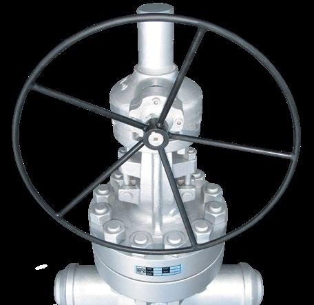
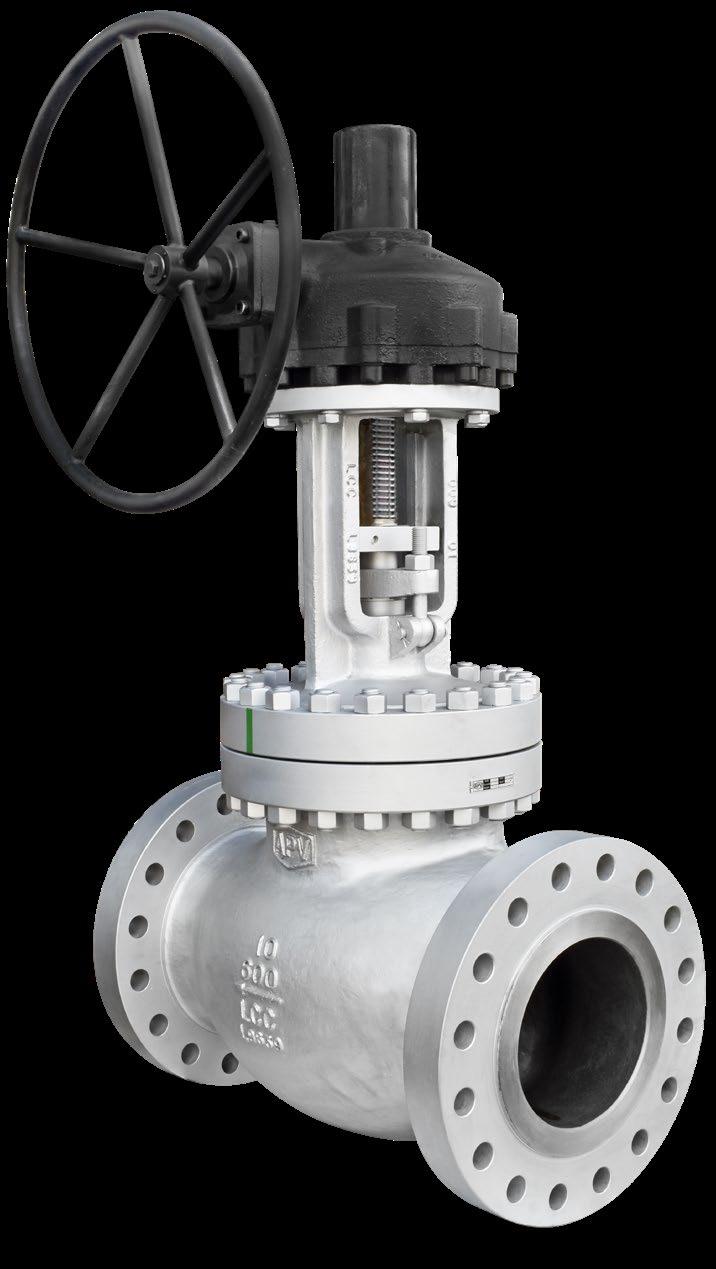
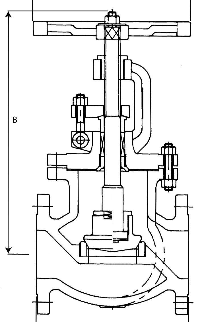
ANSI CLASS 150 ~ 2500
• Bolted bonnet, OS&Y, Swivel Disc. • Plug type disc (Ball type also available).
• On smaller sizes, the yoke is cast integral with bonnet. Larger sizes have two piece yoke, refer to individual drawing.
• Stem nut is mounted with ball bearings to reduce operating torque for ease of manual operation in larger sizes and higher classes.
Body Guided Disc style eliminates side thrust and provides longer disc, seat and body life as well as ensuring positve shut-off and low closing torque.
Torque Arm

• Valves designed to ASME B16.34 / API 623 wall thickness to API 623
• Valves tested to API Std. 598
• Face-to-face to ANSI B16.10
• Flanged ends to ANSI B16.5
• Butt-welding ends to ANSI B16.25
• Trim and seating surface as per API 600
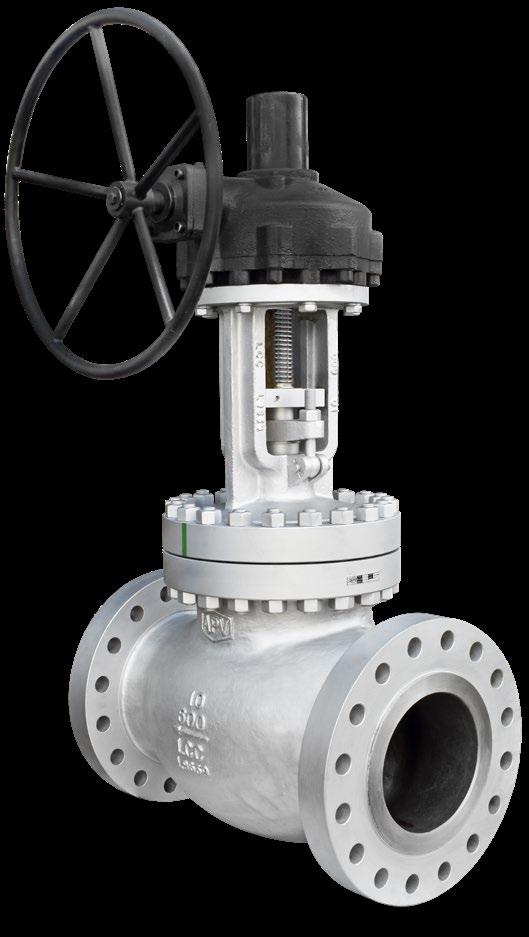
• Stuffing box smoothness ≤Ra 3.2 µm (superior to API 623 / API 600)
• Stem smoothness to API 623 ≤Ra 0.80 µm
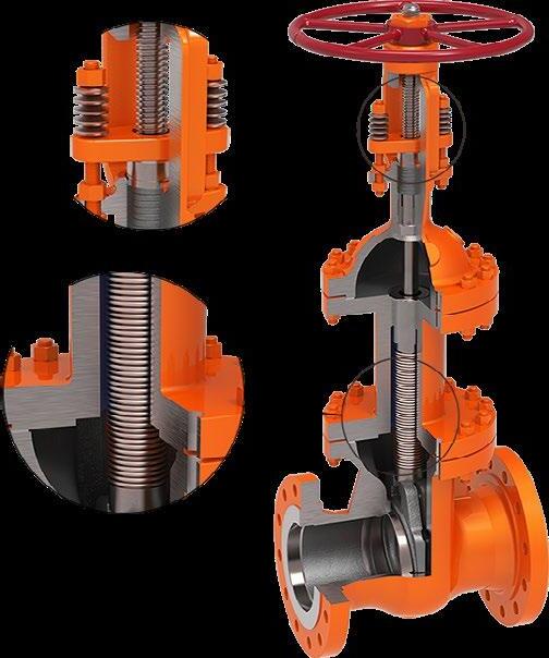
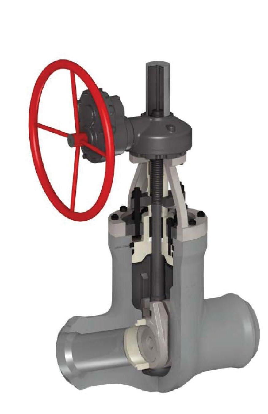
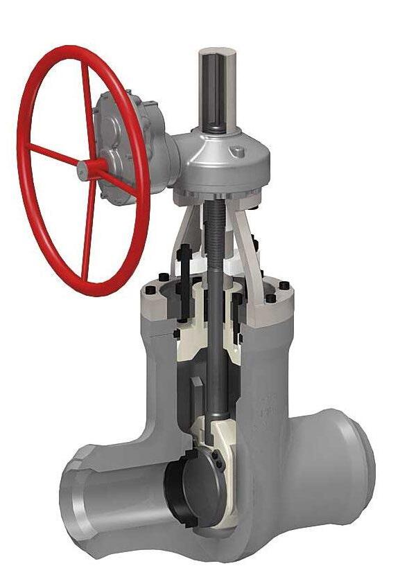
Used in larger sizes the torque arm prevents stem movement which reduces wear on packing rings and enables better sealing as well as reducing torque. Non rotating stem, only the stem nut rotates. The arm also provides visual stem position indication and can be interfaced with position switches. Optional live loaded packing system is shown.


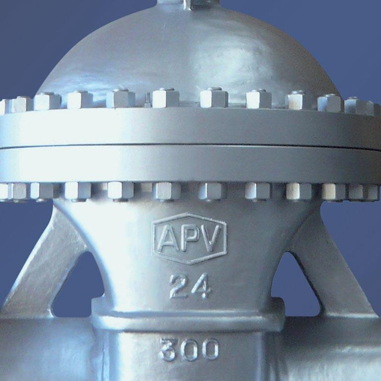
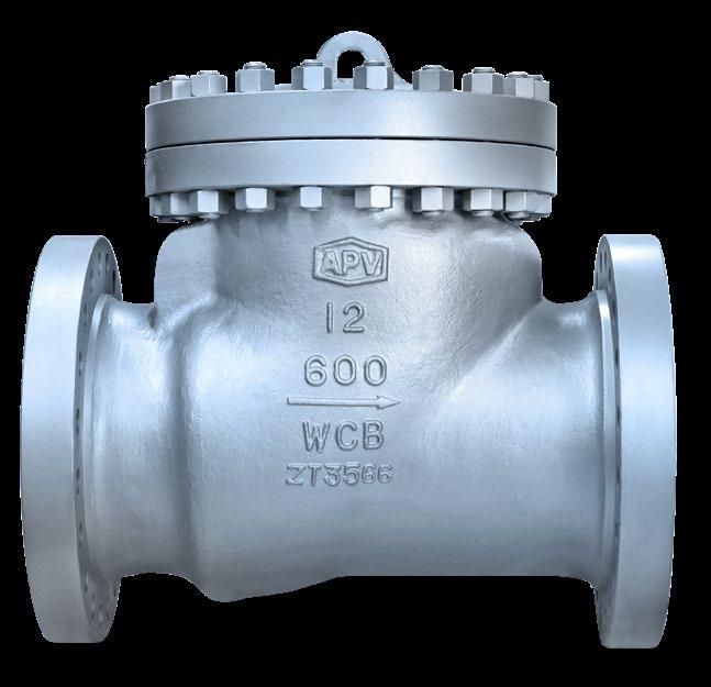
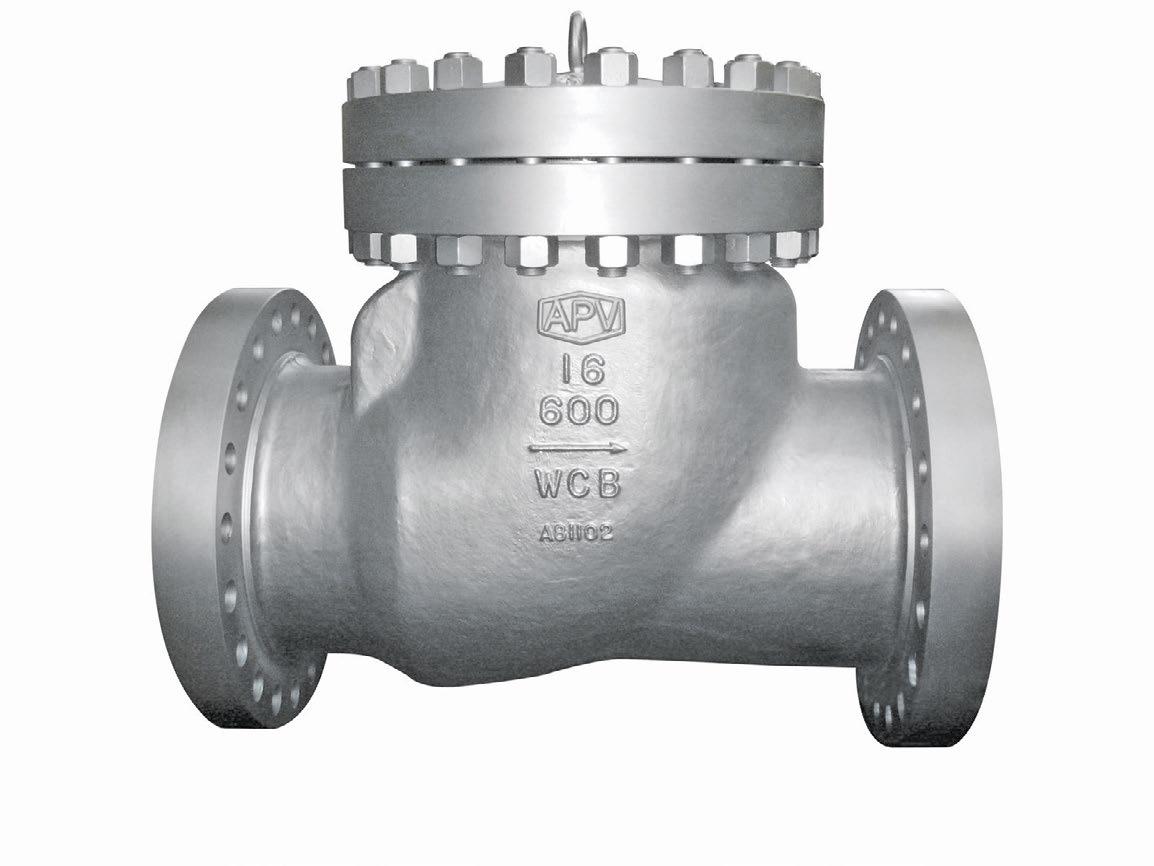
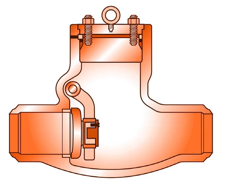
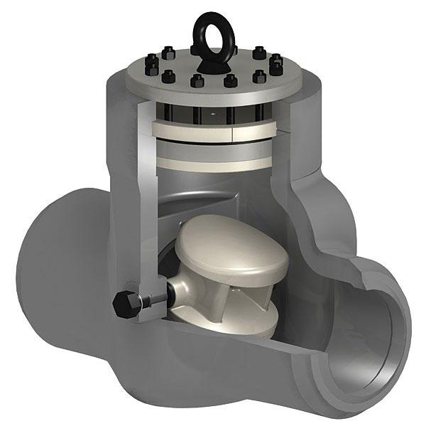
CAST STEEL CHECK VALVES
ANSI CLASS 150 ~ 2500
FEATURES
• Bolted or pressure seal bonnet
• Swing disc
APPLICABLE STANDARDS
• Valves designed to ASME B16.34 and API 594/API 6D
• Valves tested to API Std. 598/API 6D/ISO 5208
• Face-to-face to ANSI B16.10
• Flanged ends to ANSI B16.5
• Butt-welding ends to ANSI B16.25
• Trim and seating surface as per API 600 standard.
LIST
1
2
3
4
5
6
8
The material is according to ASTM standard. * Eye bolt supplied in larger sizes & higher classes.
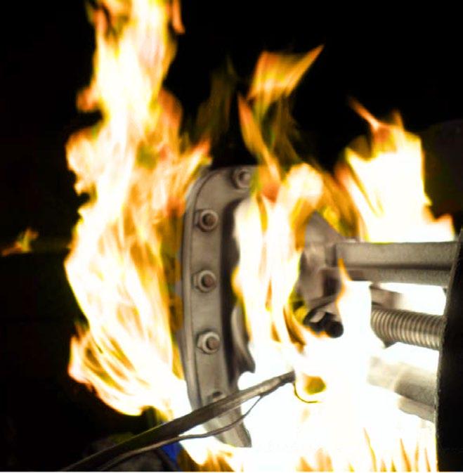
API 6FD & API 6FA-5th Firesafe Certified (API 6D Version)

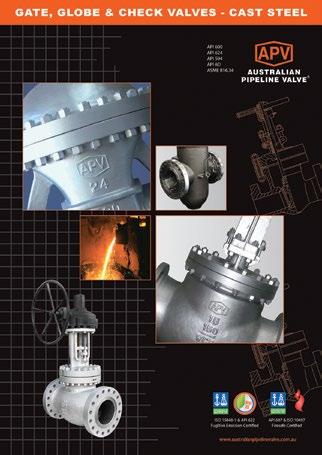
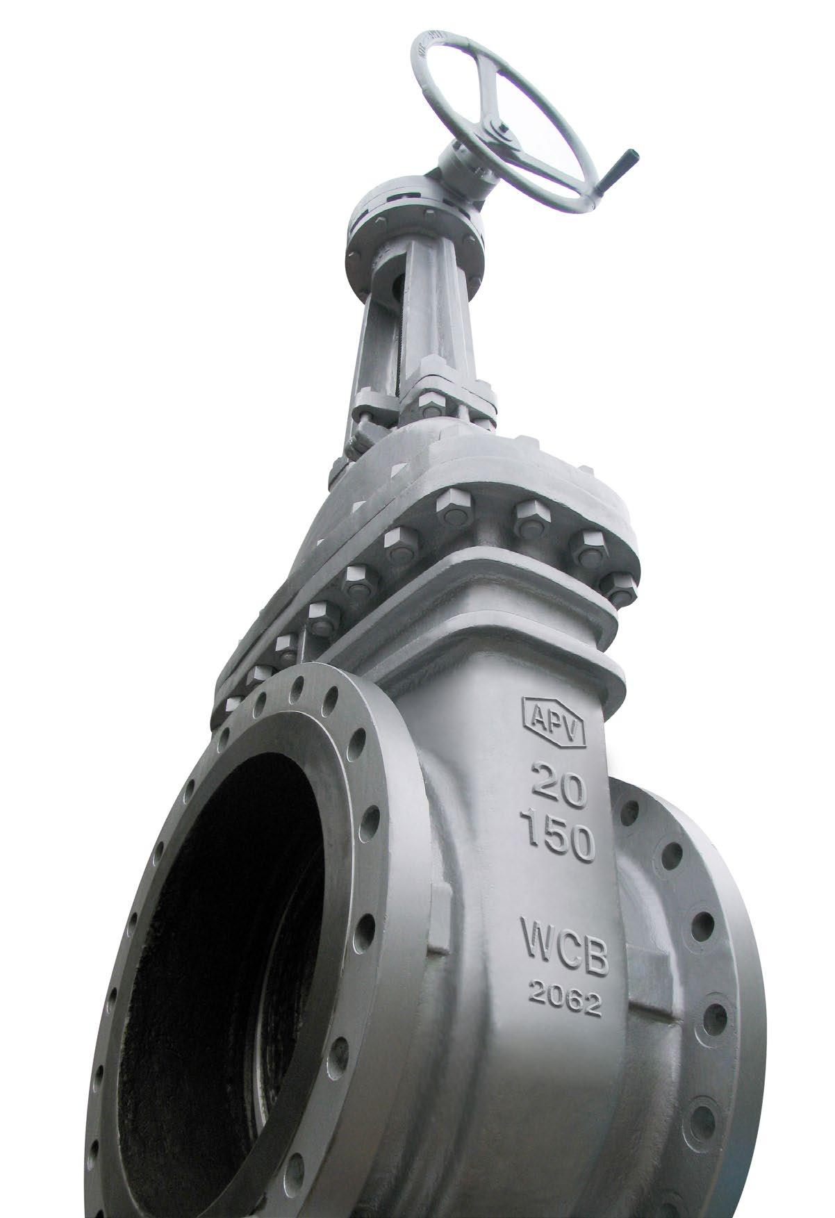
Cast steel valves are designed and manufactured to conform with API, ASTM, ANSI and other applicable internationally recognised standards, to possess all the qualities to meet with stringent requirement criteria of petroleum, petro-chemical and general industrial applications.

Valves are tested in accordance with applicable API standards. Full traceability is maintained.
Valves offer the option of hard facing on the wedge (disc) and seating areas.
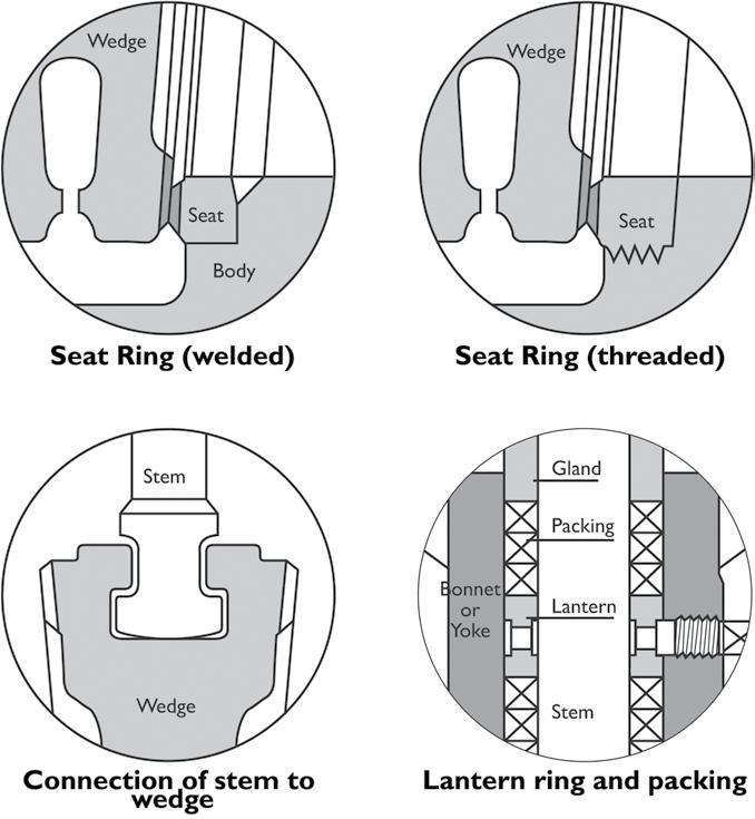
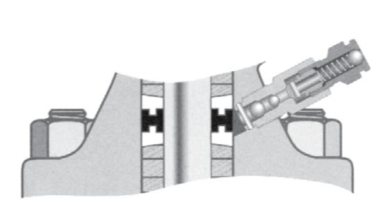
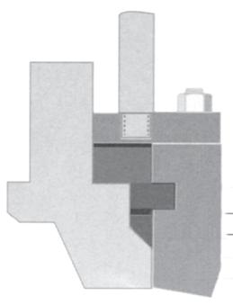
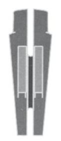
Gate Valves are optionally available with lantern rings. These rings along with double packing provide a leak-off connection. Alongside are illustrations of lantern rings as well as disc connection. Fugitive emission packing sets do normally need a lantern ring.
APV offers fugitive emission service valves on special request. The valves comply with environmental protection requirements. APV fugitive emission valves are designed, manufactured and tested to meet less than 100ppm with packing conforming to API 622 and valve design tested to API 624 and ISO 15848-1. Furthermore, optional live-loading of packing bolts is available. Two sets of belleville plate springs maintain a permanent packing stress of 24,000-28,000 kPa. Live-loading extends low emission service life especially in service with high pressure/temperature transients.
The stem on all APV fugitive emission service valves is surface finished to ≤Ra 0.80 µm. Straightness and roundness are precisely controlled. The stuffing box has a maximum ≤Ra 3.2 µm surface finish. Cylindricity and verticality are precisely controlled.
Shell wall thickness and general valve design specifications
API 600 (Gate Valves)
API 603 (Gate Valves)
API 594 (Check Valves)
API 623 (Globe Valves)
B16.34
B16.10 Flanged end dimensions
B16.5*
B16.25
Live Loading is an addition of spring washers to the gland studs to maintain the packing load of the valve over time.
The bellow seal replaces the dynamic sealing system of a stem packing by a static sealing system between the valve bonnet and the valve stem bottom. It prevents the valve from the risk of leakage from the valve packing for VOC or toxic services.
Full body wedge guides allow correct wedge alignment. Yoke sleeve with bearings reduce torque for easy operation. Seat rings allow easy access for maintenance and packing replacement is simple. Seat face 13Cr hardfaced, ground and lapped to a Ra 0.4~0.8 µm finish. Wedge is ground and lapped to a Ra 0.4~0.8 µm finish and tightly guided to prevent dragging and seat damage. Non-rotating stem with precision Acme threads and burnished finish. Rotating stem nut is austenitic ductile iron Gr. D-2C renewable.
API 600 and ANSI B16.34. Dimensions to ANSI B16.10 and ISO 5727. Stuffing box smoothness ≤Ra 3.2 µm superior to API 600. Stem smoothness ≤Ra 0.80 µm as per API 600.
All gate valves are available with optional PTFE seat rings. The moulded PTFE ring is bonded into a seat ring groove in the face for maximum service life. This design is excellent for lower temperature service where tight shutoff is required.
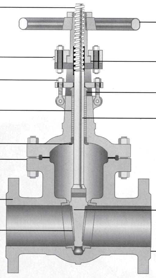
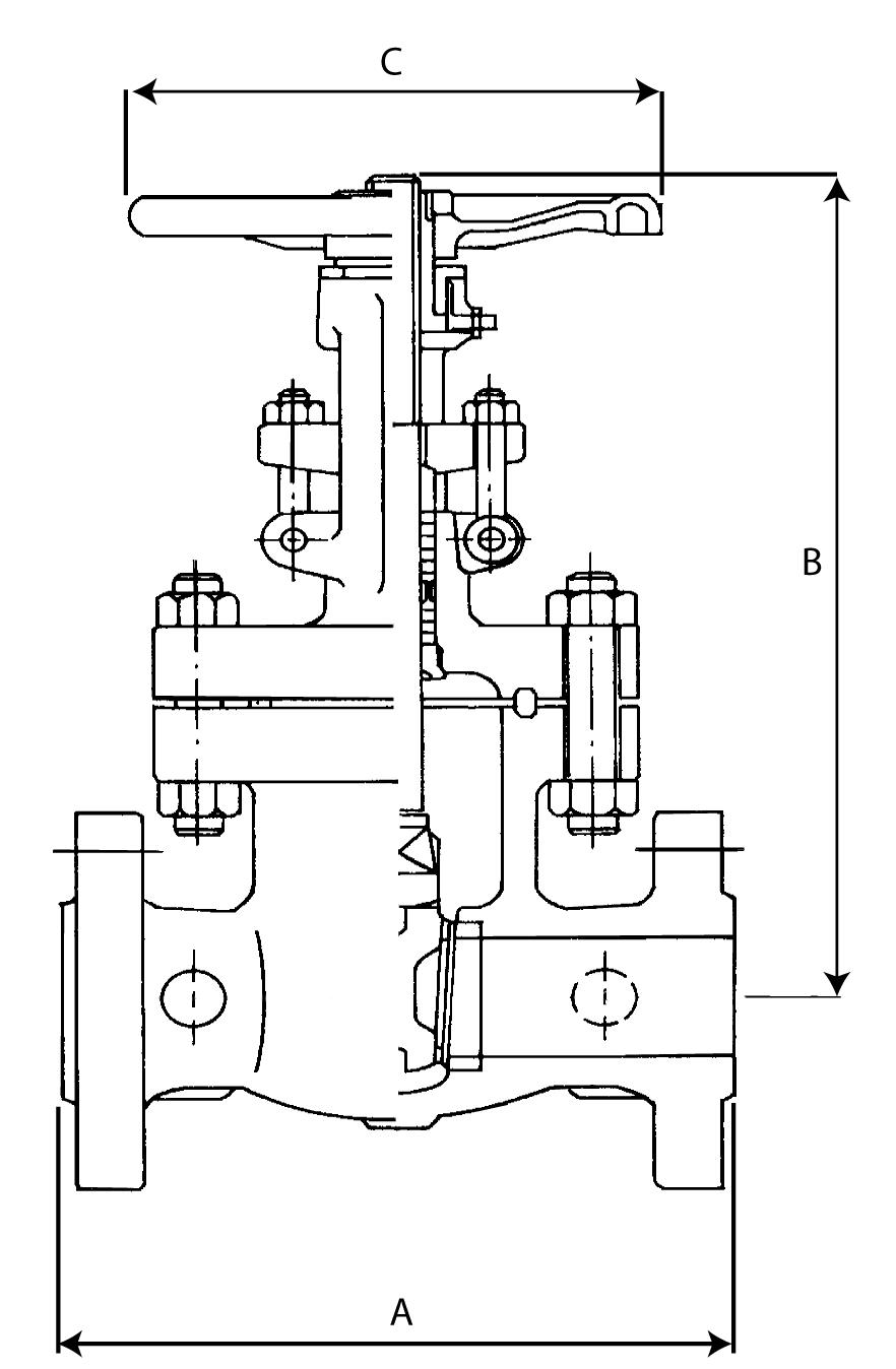
Handwheel
Rising Stem - provides open-close indication 3. Grease Fitting - to minimise wear and operating torque 4. Yoke Sleeve - furnished in ductile Ni-resist or aluminium-bronze for low torque operation
Parallel slide style also available, see page 20, 84 - 88 and also see APV Steamco Catalogue
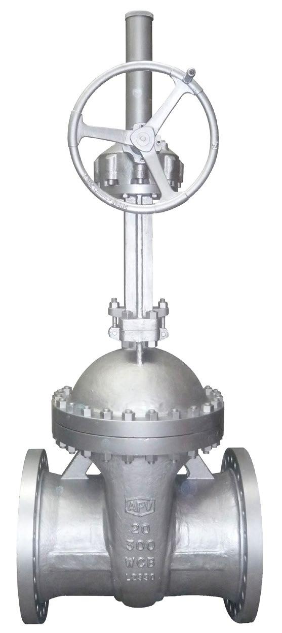
5. Swing Bolt - easier maintenance and packing replacement
6. Gland - flange is self-aligning to eliminate stem damage
7. Stuffing Box
8. Stem - upset forge T-head stems to eliminate possibility of a bent stem jamming the valve
9. Backseat - provides back-up stem seal
10. Bonnet Joint
11. Body - full ported, heavy wall body API 600 wall thickness 12. Wedge - heavy pattern. Available in solid & flex wedge
Seat Ring - full ported rings for easy maintenance
End Connections - flanged or
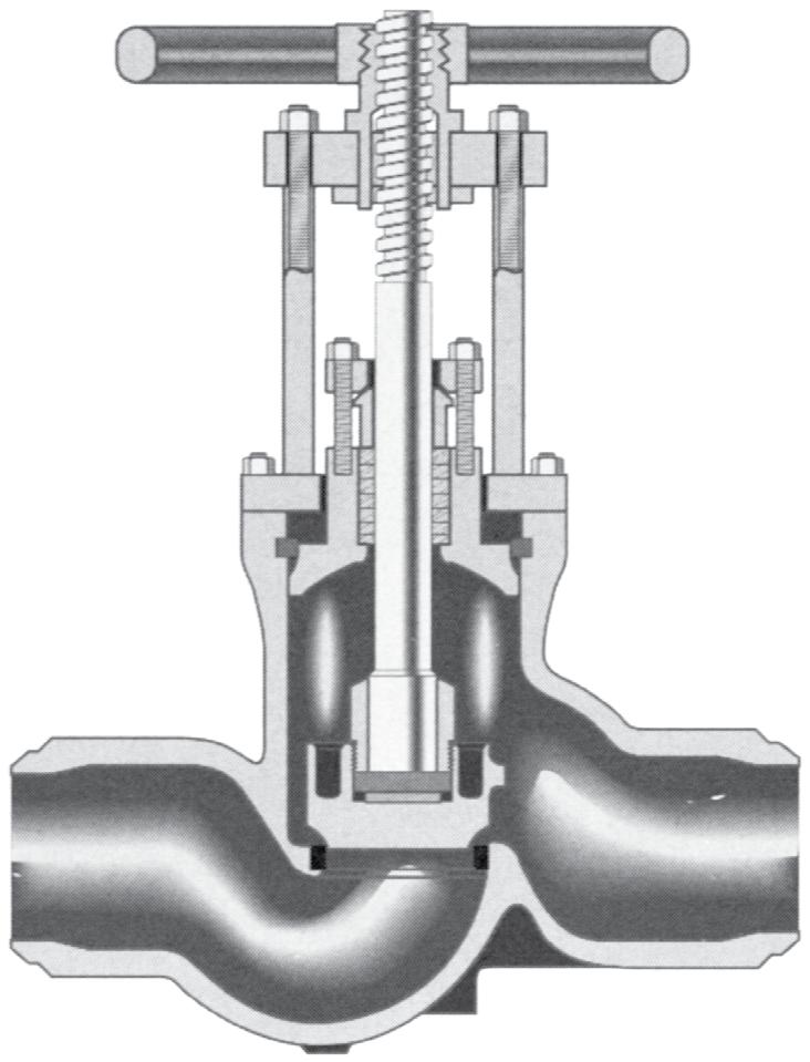
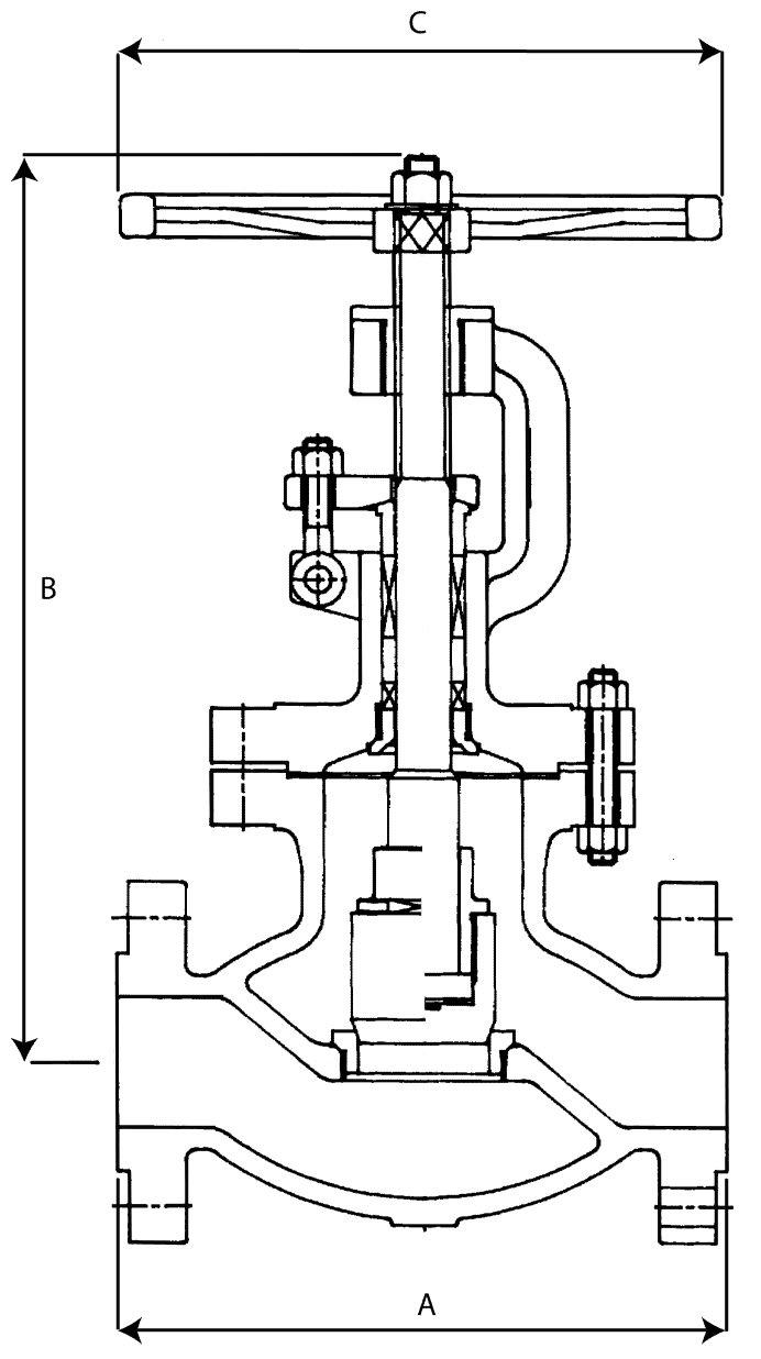
Seat rings are easily accessible for repair or replacement. Australian Pipeline Valve globe valves are for services requiring frequent operation for on-off isolation service as well as throttling. Never attempt throttling at under 20% of stem travel. Closer throttling, can result in higher pressure drops which may cause excessive velocities or cavitation and could cause vibration or high noise levels resulting in damage to the valve or adjacent components/structure.
Heavy construction provides years of reliable service.
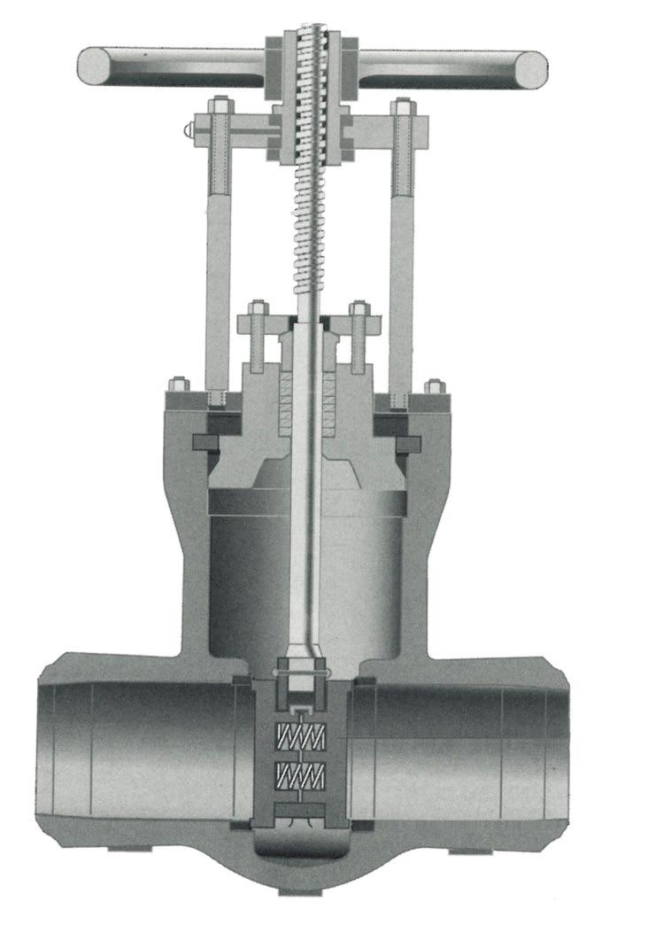
Available in bolted and pressure seal bonnet, outside screw and yoke, rising stem with ball or plug type disc, and have flanged or butt weld ends. Screw down non-return (Stop check) also available. Stem with precision Acme threads and burnished finish. Valve suitable for horizontal installation. Conical seating surfaces 13Cr hardfaced/stellite, ground and lapped to a Ra 0.4~0.8 µm finish. Tapered plug type disc as standard. Body guided disc on larger sizes, and higher classes on smaller sizes, accurately mates the hardfaced surface of the disc with the surface of the seat. Body and bonnet joint accurately machined. Fully enclosed gasket. Rotating stem nut, austenitic ductile iron Gr. D-2C, renewable in-line.
To ASME B16.34 / API 623. Dimensions to ASME B16.10 and ISO 5752. Wall thickness, stem smoothness and stuffing box finish complies with API 623. APV stuffing box smoothness ≤Ra 3.2 µm superior to API 623 / API 600. Stem smoothness ≤Ra 0.80 µm as per API 623.

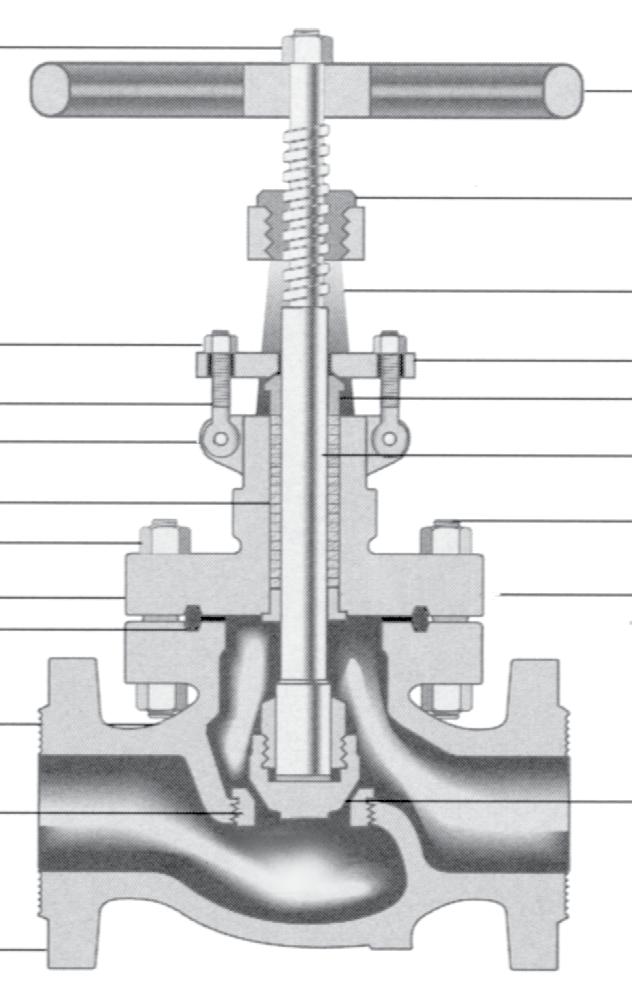
1. Yoke Sleeve - furnished in aluminium-bronze to reduce torque. Larger sizes furnished with bearings 2. Handwheel 3. Swing Bolts - easier maintenance
4. Gland - self-aligning to eliminate stem damage
5. Stuffing Box
6. Stem - heavy duty
7. Backseat - provides back-up stem seal
8. Bonnet Joint - ring joint or spiral according to ANSI class
9. Seat Rings - separate heavy duty, full ported rings for easy maintenance
10. Disc - heavy duty disc plug design
11. End Connections - flanged or butt weld ends
12. Body - full ported, with API 600 / API 623 heavy wall thickness
Stem guide - (Optional) for reduced packing
623 Guided disc style (Non Rotating Stem Version)


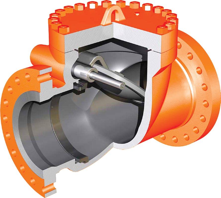
Australian Pipeline Valve valves are designed to provide fast valve action and maximum life. All valves are full ported, have full API 594/API 600 wall thickness, and meet the requirements of ANSI B16.34. Full opening API 6D (piggable) type also available on request.
ASME B16.34 / API 594 /API 6D as applicable.
Check valves are designed to close quickly in either horizontal or vertical (flow up) pipe runs. The body seat ring is installed on a 3° angle. This allows our check valve to close even when installed in horizontal pipe run with no pressure.
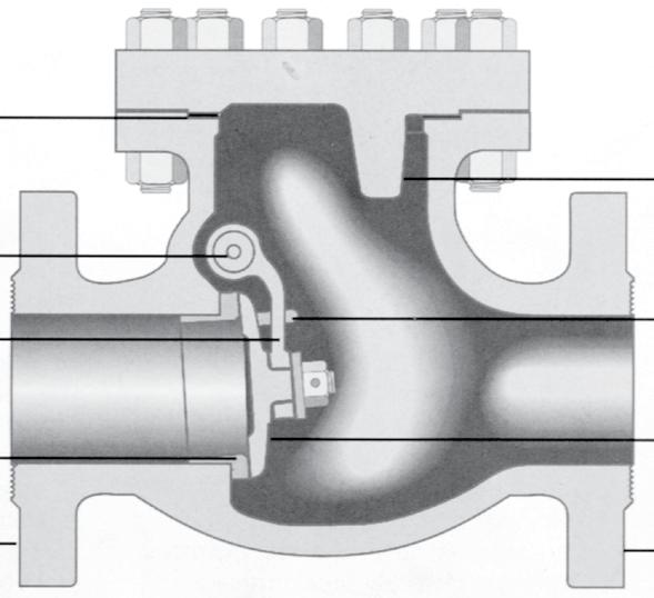
1. Disc Stop - provides positive stop in open position
2. Bonnet Joint - (ring or spiral according to class)
3. Hinge Pin - solid pin for maximum strength
4. Securing Lugs - allow disc to seat freely and prevent disc spinning
5. Hinge - designed to withstand shock and load of quick closing
6. Disc - disc is bolted and pinned to hinge; ground seating surface is mated to seat ring for positive shut off
7. Seat Ring - Full port seal welded or screwed
8. End Connections - flanged or buttweld
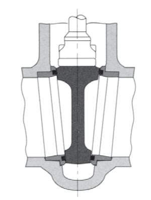
The wedge is a one piece, fully guided wedge. Available in flex wedge and solid wedge. (Flexible wedge allows the seating faces to move to compensate for thermal expansion). Wedging actions allows a tight seal even in low differential pressure services. Flexible wedge construction resists wedge sticking in service where the valve may be closed when hot and opened when cold. Seating surfaces are hardfaced for long life.
Parallel slide also available, see page 20, 84 - 85 and also see APV Steamco Catalogue.
1. Yoke Sleeve - aluminium-bronze yoke sleeve has thrust bearings to minimise torque
2. Hand Wheel - (or gear in larger sizes)
3. Yoke - offering ease of maintenance
4. Stem - The design allows the wedge to self-align, eliminating the possibility of jamming the wedge
5. Gland - two piece, self-aligning gland eliminates cocking. Swing out bolting facilitates maintenance
6. Back Seat - Integral, hardfaced
7. Pressure Seal - retaining ring and mild steel silver plated/SS/ SS+GRP gasket to aid disassembly and provide maximum seal
8. Seat Ring - hardfaced seat rings are welded to body. Tapered design provides clear flow path 9. Wedge - one-piece, fully guided. Parallel seat also available
Body - streamlined flow path minimises pressure drop.
Normally utilised for shut off service but are not recommended for throttling. Gate valves are normally installed in horizontal pipe runs with the valve stem vertically up. They can be installed in horizontal or vertical pipe runs. After closing with sufficient force, the stem should be backed off slightly (1/8 turn) to relieve stem load. Parallel Slide Valves have self aligning discs with no wedging force and react freely to thermal changes. The design also ensures uniform seat wear and ease of maintenance. Parallel Slide Gate Valves are ideal where high differential pressure or thermal expansion may cause sticking of wedge to gate in traditional gate valves.
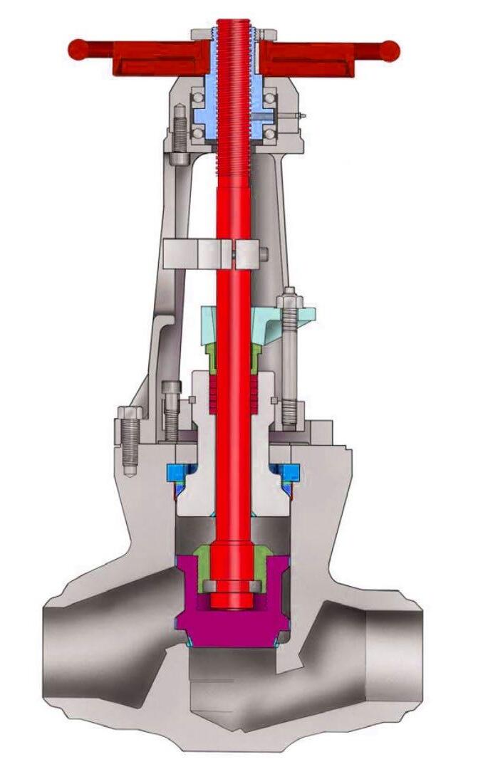
The torque arm design guides and centralises the stem and prevents stem movement which reduces wear on packing rings & enables better sealing as well as reducing torque. Only the stem nut rotates. The arm also provides visual stem position indication & can be interfaced with position switches. Optional live loaded packing system is shown.
1. Yoke Sleeve - aluminium-bronze yoke sleeve with thrust bearings for ease of opening
2. Actuation - Low torque seating design reduces actuation costs
3. Yoke - designed to offer ease of maintenance
4. Stem - Threaded into disc housing and also pinned
5. Gland - two piece, self-aligning gland eliminates cocking. Swing out bolting facilitates maintenance
6. Back Seat - Integral, hardfaced
7. Pressure Seal - retaining ring and mild steel silver plated/SS/SS+GRP gasket to aid disassembly and provide maximum seal
8. Seat Ring - hardfaced seat rings are welded to body and are designed for ease of maintenance
9. Discs - Spring loaded discs are self-aligning and reduce actuator torque requirements
10. Integral Stop - Integral stop positions for reliable
Australian Pipeline Valve Globe valves are installed with pressure and flow under the disc. Globe valves are suitable for most throttling applications; they should not be used for throttling at less than 10% open. Stop Check Valves have a guided loose disc allowing the valve to act as a combination globe valve and check valve.
API 622 & ISO 15848-1
Fugitive Emission Certified
API 607-7th & ISO 10497
Firesafe Certified
seat and body life as well as ensuring positve shut-off and low closing torque.
The torque arm design guides and centralises the stem and prevents stem movement which reduces wear on packing rings & enables better sealing as well as reducing torque. Only the stem nut rotates. The arm also provides visual stem position indication & can be interfaced with position switches. Optional live loaded packing system is shown.
1. Yoke Sleeve - aluminium-bronze yoke sleeve minimizes operating torque. Larger sizes have needle bearing type thrust bearings
2. Actuation - Manual handwheel gear operator or actuated 3. Yoke - designed to offer ease of maintenance
4. Stem - precision-ground stem has upset tee-head for reliable stem/wedge connection
5. Gland - two piece, self-aligning gland eliminates cocking. Swing out bolting facilitates maintenance
6. Back Seat - Integral, hardfaced
7. Pressure Seal - uncomplicated design has segmented retaining ring and mild steel silver plated/SS/SS+GRP gasket to aid disassembly and provide maximum bonnet seal
8. Hardened Seating Surfaces - both disc and body seating surfaces are hard faced for maximum service life
9. Disc - fully body guided for positive seating
10. Body - Full port ‘s’ pattern design available to minimise pressure drop
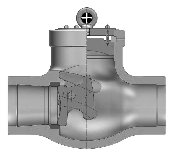
Australian Pipeline Valve Check valves are installed with pressure and flow under the disc.
Reduced maintenance is assured because the disc is the only moving part and is designed to minimise flutter in the closed position, thus reducing wear on the pivot pin, disc, and seat.
Loss of head is minimised by the balanced disc and its ‘aerofoil’ design. Short distance of travel, combined with a balanced disc allows rapid closure while minimising slamming.
Drip tight seating is accomplished over the full pressure range because a slight clearance at the pivot pin assures complete seating between the disc ring and body ring.
The hinge pin located near the center of gravity allows the conical seating face of the disc to move out and into the seat rapidly without sliding or wear. The disc pivots through a small arc preventing backflow and ‘water hammer’. Superior tightness - conical, lapped-in hardfaced seating is self aligning. Valve can be used in horizontal but also even in vertical piping with flow up.
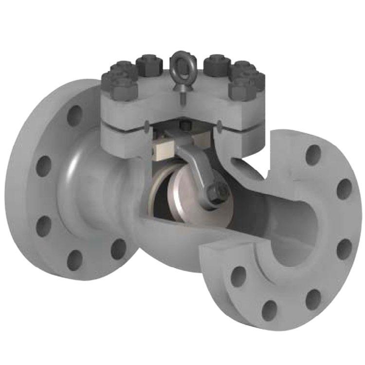
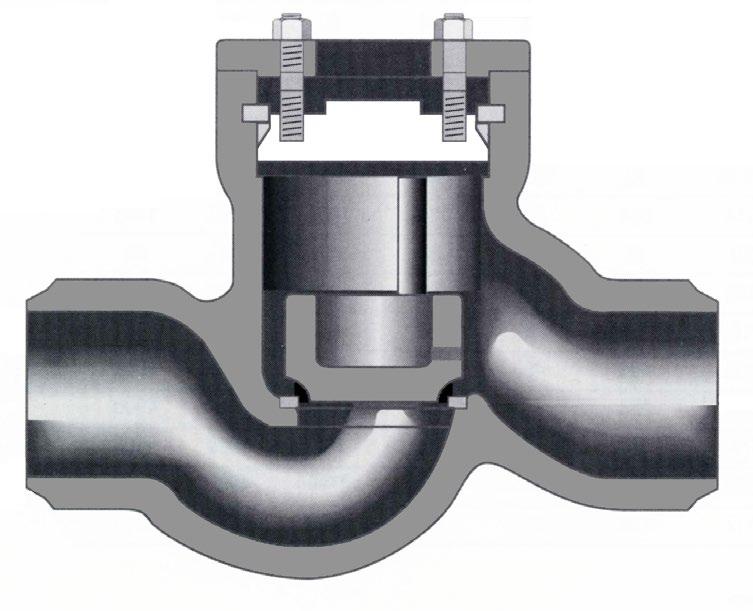
Piston Lift Check valves are generally used in applications where pressure drop through the valve is not critical, although APV piston check valves have a relatively low pressure drop. available in horizontal, right angle, Y patterned (inclined) and vertical designs. Excellent for low or pulsating flows with good to moderate sealing capability. APV offers fully guided disc through the total travel.
Piston Lift Check Valves may be equipped with equaliser lines to vent the bonnet area above the disk and eliminate any dash-pot effect during rapid operation. An aspirator is also available with an adjustable valve to control disc opening and closing speed.
Description
Body
Steel A216 Gr. WCB
Bonnet Carbon Steel A216 Gr. WCB
Disc / Facing Stainless Steel A216 Gr. WCB+410SS/CR13 or Stellite/HF
Stem Stainless Steel A276 Gr.410 or A182 Gr. F6a/CR13
Hand Wheel Ductile Iron A536 Gr. 65-45-12
Seat / Facing Stainless Steel/HF A105/F6a+410SS/CR13/Stellite
Back Seat Ring Stainless Steel A276 Gr. 410 or A182 Gr. F6a
Yoke Sleeve Ductile Iron or Bronze A439 Gr. D2C or B62
Sleeve Gland Carbon Steel A216 Gr. WCB
Gland Flange Carbon Steel A105
Gland Ring Stainless Steel A182 Gr. F6a Wheel Nut Carbon Steel A105
Bonnet Bolt Alloy Steel A193 Gr. B7/B7M
Bonnet Nut Alloy Steel A194 Gr. 2H/2HM
Gland Bolt Alloy Steel A193 Gr. B7
Gland Nut Alloy Steel A194 Gr. 2H
Gland Bolt Pin Alloy Steel A108 Gr. 1020
Bearing - Thrust Ball
Grease Nipple Carbon Steel A307 Gr. B
Set Screw Carbon Steel A307 Gr. B
Name Plate Stainless Steel 304/AL
Packing Asbestos Free Reinforced Graphite
Gasket 316/Graphite Reinforced Graphite 316 Tanged
Description Material Specs.
Body Carbon Steel A216 Gr. WCB
Bonnet Carbon Steel A216 Gr. WCB
Disc / Facing Stainless Steel A216 Gr. WCB+410SS/CR13 or Stellite/HF
Stem Stainless Steel A276 Gr.410 or A182 Gr. F6a/CR13
Hand Wheel Ductile Iron A536 Gr. 65-45-12
Seat / Facing Stainless Steel/HF A105/F6a+410SS/CR13/Stellite
Back Seat Ring Stainless Steel A276 Gr. 410 or A182 Gr. F6a
Yoke Sleeve Ductile Iron or Bronze A439 Gr. D2C or B62
Sleeve Gland Carbon Steel A216 Gr. WCB
Gland Flange Carbon Steel A105
Gland Ring Stainless Steel A182 Gr. F6a
Wheel Nut Carbon Steel A105
Bonnet Bolt Alloy Steel A193 Gr. B7/B7M
Bonnet Nut Alloy Steel A194 Gr. 2H/2HM
Gland Bolt Alloy Steel A193 Gr. B7
Gland Nut Alloy Steel A194 Gr. 2H
Gland Bolt Pin Alloy Steel A108 Gr. 1020
Bearing - Thrust Ball
Grease Nipple Carbon Steel A307 Gr. B
Set Screw Carbon Steel A307 Gr. B
Name Plate Stainless Steel 304/AL
Packing Asbestos Free Reinforced Graphite
Gasket Spiral Wound 304/316 Graphite filled
DIMENSIONS (MM)
For 1/2” to 1” dimensions see page 58 and overview brochure. For RTJ & 5” dimensions see overview brochure.
Size
1655 2320
For CF8/CF8M 300Lb gate see page 58. * For Buttweld weights see overview brochure.
Description
Specs.
Body Carbon Steel A216 Gr. WCB
Bonnet Carbon Steel A216 Gr. WCB
Disc / Facing Stainless Steel A216 Gr. WCB+410SS/CR13 or Stellite/HF
Stem Stainless Steel A276 Gr.410 or A182 Gr. F6a/CR13
Hand Wheel Ductile Iron A536 Gr. 65-45-12
Seat / Facing Stainless Steel/HF A105/F6a+410SS/CR13/Stellite
Back Seat Ring Stainless Steel A276 Gr. 410 or A182 Gr. F6a
Yoke Sleeve Ductile Iron or Bronze A439 Gr. D2C or B62
Sleeve Gland Carbon Steel A216 Gr. WCB
Gland Flange Carbon Steel A105
Gland Ring Stainless Steel A182 Gr. F6a
Wheel Nut Carbon Steel A105
Bonnet Bolt Alloy Steel A193 Gr. B7/B7M
Bonnet Nut Alloy Steel A194 Gr. 2H/2HM
Gland Bolt Alloy Steel A193 Gr. B7
Gland Nut Alloy Steel A194 Gr. 2H
Gland Bolt Pin Alloy Steel A108 Gr. 1020
Bearing - Thrust Ball
Grease Nipple Carbon Steel A307 Gr. B
Set Screw Carbon Steel A307 Gr. B
Name Plate Stainless Steel 304/AL
Packing Asbestos Free Reinforced Graphite
Gasket Metal Ring Joint or Spiral Wound SS Graphite filled
Description Material Specs.
Body Carbon Steel A216 Gr. WCB
Bonnet Carbon Steel A216 Gr. WCB
Disc / Facing Stainless Steel A216 Gr. WCB+410SS/CR13 or Stellite/HF
Stem Stainless Steel A276 Gr.410 or A182 Gr. F6a/CR13
Hand Wheel Ductile Iron A536 Gr. 65-45-12
Seat / Ring Carbon Steel/HF A105/F6a+410SS/CR13/Stellite
Back Seat Ring Stainless Steel A182 Gr. F6a
Yoke Sleeve Ductile Iron or Bronze A439 Gr. D2C or B62
Sleeve Gland Carbon Steel A216 Gr. WCB
Gland Flange Carbon Steel A105
Gland Ring Stainless Steel A182 Gr. F6a
Wheel Nut Carbon Steel A105
Bonnet Bolt Alloy Steel A193 Gr. B7/B7M
Bonnet Nut Alloy Steel A194 Gr. 2H/2HM
Gland Bolt Alloy Steel A193 Gr. B7/B7M
Gland Nut Alloy Steel A194 Gr. 2H.2HM
Gland Bolt Pin Alloy Steel A108 Gr. 1020
Bearing - Thrust Ball
Grease Nipple Carbon Steel A307 Gr. B
Set Screw Carbon Steel A307 Gr. B
Name Plate Stainless Steel 304/AL
Packing Asbestos Free Reinforced Graphite
Gasket Metal Ring Joint or Spiral Wound SS, Graphite filled
Description
Specs.
Body Carbon Steel A216 Gr. WCB
Bonnet Carbon Steel A216 Gr. WCB
Disc Facing Stainless Steel A216 Gr. WCB+410SS/CR13 or Stellite/HF
Stem Stainless Steel A276 Gr.410 or A182 Gr. F6a/CR13
Hand Wheel Ductile Iron A536 Gr. 65-45-12
Seat / Ring Carbon Steel/HF A105/F6a+410SS/CR13/Stellite
Back Seat Ring Stainless Steel A182 Gr. F6a
Yoke Sleeve Ductile Iron or Bronze A439 Gr. D2C or B62
Sleeve Gland Carbon Steel A216 Gr. WCB
Gland Flange Carbon Steel A105
Gland Ring Stainless Steel A182 Gr. F6a
Wheel Nut Carbon Steel A105 Zn. Plating
Bonnet Bolt Alloy Steel A193 Gr. B7/B7M
Bonnet Nut Alloy Steel A194 Gr. 2H/2HM
Gland Bolt Alloy Steel A193 Gr. B7/B7M
Gland Nut Alloy Steel A194 Gr. 2H/2HM
Gland Bolt Pin Alloy Steel A108 Gr. 1020
Bearing - Thrust Ball
Grease Nipple Carbon Steel A307 Gr. B
Set Screw Carbon Steel A307 Gr. B
Name Plate Stainless Steel 304/AL
Packing Asbestos Free Reinforced Graphite
Gasket Metal Ring Joint or Spiral Wound SS Graphite filled
Description Material Specs.
Body Carbon Steel A216 Gr. WCB
Bonnet Carbon Steel A216 Gr. WCB
Disc / Facing Stainless Steel A216 Gr. WCB+410SS/CR13/Stellite
Stem Stainless Steel A276 Gr.410 or A182 Gr. F6a
Hand Wheel Ductile Iron A536 Gr. 65-45-12
Seat Stainless Steel A182 Gr. F6a/CR13-Stellite/HF
Back Seat Ring Stainless Steel A276 Gr.410 or A182 Gr. F6a
Gland Flange Carbon Steel A105
Gland Ring Stainless Steel A182 Gr. F6a /A276 Gr.410
Disc Gland Stainless Steel A217 Gr. CA-15/A276 Gr.410
Yoke Bush Stainless Steel or Bronze A439 Gr. D2C or B62
Bonnet Bolt Alloy Steel A193 Gr. B7/B7M
Bonnet Nut Alloy Steel A194 Gr. 2H/2HM
Gland Bolt Alloy Steel A193 Gr.B7
Gland Nut Alloy Steel A194 Gr. 2H
Gland Bolt Pin Alloy Steel A108 Gr. 1020
Wheel Nut Stainless Steel A192 Gr. 8/A105
Name Plate Stainless Steel 304/AL
Packing Asbestos Free Reinforced Graphite
Gasket Spiral Wound 304/316 Graphite filled
*Stuffing box chamber & stem smoothness to API 623 and API 600
Body Guided Disc
Body guided disc style eliminates side thrust and provides longer disc, seat and body life as well as ensuring positve shut-off and low closing torque.
For RTJ dimensions and 5” dimensions, see overview brochure. For 1/2” to 1 1/2” see page 59 and overview brochure. For CF8/CF8M Globe 150Lb see page 59.
Description Material Specs.
Body Carbon Steel A216 Gr. WCB
Bonnet Carbon Steel A216 Gr. WCB
Disc / Facing Stainless Steel A216 Gr. WCB+410SS/CR13/Stellite
Stem Stainless Steel A276 Gr.410 or A182 Gr. F6a
Hand Wheel Ductile Iron A536 Gr. 65-45-12
Seat Stainless Steel A182 Gr. F6a/CR13, Stellite/HF
Back Seat Ring Stainless Steel A276 Gr.410 or A182 Gr. F6a
Gland Flange Carbon Steel A105
Gland Ring Stainless Steel A182 Gr. F6a /A276 Gr.410
Disc Gland Stainless Steel A217 Gr. CA-15 /A276 Gr.410
Yoke Bush Stainless Steel or Bronze A439 Gr. D2C or B62
Bonnet Bolt Alloy Steel A193 Gr. B7/B7M
Bonnet Nut Alloy Steel A194 Gr. 2H/2HM
Gland Bolt Alloy Steel A193 Gr.B7/2HM
Gland Nut Alloy Steel A194 Gr. 2H
Gland Bolt Pin Alloy Steel A108 Gr. 1020
Wheel Nut
Steel A194 Gr. 8/A105
Name Plate Stainless Steel 304/AL
Packing Asbestos Free Reinforced Graphite
Gasket Spiral Wound 304/316 Graphite filled
*Stuffing box chamber & stem smoothness to API 623 and API 600
Body Guided Disc
Body guided disc style eliminates side thrust and provides longer disc, seat and body life as well as ensuring positve shut-off and low closing torque.
For RTJ dimensions 2” - 16” and 5” RF/RTJ dimensions, see overview brochure.
For 1/2” to 1-1/2” see page 59 and overview brochure.
For CF8/CF8M Globe 300# see page 59.
Torque Arm
Used in larger sizes the torque arm prevents stem movement which reduces wear on packing rings and enables better sealing as well as reducing torque. Non rotating stem, only the stem nut rotates. The arm also provides visual stem position indication and can be interfaced with position switches. Optional live loaded packing system is shown. A (BW)
Description Material Specs.
Body Carbon Steel A216 Gr. WCB
Bonnet Carbon Steel A216 Gr. WCB
Disc / Facing Stainless Steel A216 Gr. WCB+410SS/CR13/Stellite
Stem Stainless Steel A276 Gr.410 or A182 Gr. F6a/CR13
Hand Wheel Ductile Iron A536 Gr. 65-45-12
Seat Stainless Steel A182 Gr. F6a/CR13, Stellite/HF
Back Seat Ring Stainless Steel A276 Gr.410 or A182 Gr. F6a
Gland Flange Carbon Steel A105
Gland Ring Stainless Steel A182 Gr. F6a
Disc Gland Stainless Steel A217 Gr. CA-15
Yoke Bush Ductile Iron or Bronze A439 Gr. D2C or B62
Bonnet Bolt Alloy Steel A193 Gr. B7/B7M
Bonnet Nut Alloy Steel A194 Gr. 2H/2HM
Gland Bolt Alloy Steel A193 Gr. B7
Gland Nut Alloy Steel A194 Gr. 2H
Gland Bolt Pin Alloy Steel A108 Gr. 1020 Wheel Nut Stainless Steel A194 Gr. 8/A105
Name Plate Stainless Steel 304/AL
Packing Asbestos Free Reinforced Graphite
Gasket Metal Ring Joint or Spiral Wound SS Graphite filled
Body guided disc style eliminates side thrust and provides longer disc, seat and body life as well as ensuring positve shut-off and low closing torque.
Used in larger sizes the torque arm prevents stem movement which reduces wear on packing rings and enables better sealing as well as reducing torque. Non rotating stem, only the stem nut rotates. The arm also provides visual stem position indication and can be interfaced with position switches. Optional live loaded packing system is shown.
Description Material Specs.
Body Carbon Steel A216 Gr. WCB
Bonnet Carbon Steel A216 Gr. WCB
Disc / Facing Stainless Steel A216 Gr. WCB+410SS/CR13/Stellite
Stem Stainless Steel A276 Gr.410 or A182 Gr. F6a/CR13
Hand Wheel Ductile Iron A536 Gr. 65-45-12
Seat Stainless Steel A182 Gr. F6a/CR13, Stellite/HF
Back Seat Ring Stainless Steel A276 Gr.410 or A182 Gr. F6a
Gland Flange Carbon Steel A105
Gland Ring Stainless Steel A182 Gr. F6a
Disc Gland Stainless Steel A217 Gr. CA-15
Yoke Bush Ductile Iron or Bronze A439 Gr. D2C or B62
Bonnet Bolt Alloy Steel A193 Gr. B7/B7M
Bonnet Nut Alloy Steel A194 Gr. 2H/2HM
Gland Bolt Alloy Steel A193 Gr. B7
Gland Nut Alloy Steel A194 Gr. 2H
Gland Bolt Pin Alloy Steel A108 Gr. 1020
Wheel Nut Stainless Steel A194 Gr. 8/A105
Name Plate Stainless Steel 304/AL
Packing Asbestos Free Reinforced Graphite
Gasket Metal Ring Joint or Spiral Wound SS Graphite filled
*Stuffing box chamber & stem smoothness to API 623 and API 600 DIMENSIONS (MM)
Body guided disc style eliminates side thrust and provides longer disc, seat and body life as well as ensuring positve shut-off and low closing torque.
C.
Note:-
For 1/2” to 1-1/2” dimensions see overview brochure.
Used in larger sizes the torque arm prevents stem movement which reduces wear on packing rings and enables better sealing as well as reducing torque. Non rotating stem, only the stem nut rotates. The arm also provides visual stem position indication and can be interfaced with position switches. Optional live loaded packing system is shown.
Description Material Specs.
Body Carbon Steel A216 Gr. WCB
Bonnet Carbon Steel A216 Gr. WCB
Disc / Facing Stainless Steel A216 Gr. WCB+410SS/CR13/Stellite
Stem Stainless Steel A276 Gr.410 or A182 Gr. F6a/CR13
Hand Wheel Ductile Iron A536 Gr. 65-45-12
Seat Stainless Steel A182 Gr. F6a/CR13, Stellite/HF
Back Seat Ring Carbon Steel A276 Gr.410 or A182 Gr. F6a
Gland Flange Carbon Steel A105
Gland Ring Stainless Steel A182 Gr. F6a
Disc Gland Stainless Steel A217 Gr. CA-15
Yoke Bush Ductile Iron or Bronze A439 Gr. D2C or B62
Bonnet Bolt Alloy Steel A193 Gr. B7/B7M
Bonnet Nut Alloy Steel A194 Gr. 2H/2HM
Gland Bolt Alloy Steel A193 Gr. B7
Gland Nut Alloy Steel A194 Gr. 2H
Gland Bolt Pin Alloy Steel A108 Gr. 1020
Wheel Nut Stainless Steel A194 Gr. 8/A105
Name Plate Stainless Steel 304/AL
Packing Asbestos Free Reinforced Graphite
Gasket Metal Joint or Spiral Wound SS Graphite filled
*Stuffing box chamber & stem smoothness to API 623 and API 600
Body guided disc style eliminates side thrust and provides longer disc, seat and body life as well as ensuring positve shut-off and low closing torque.
C.
Parabolic disc for
For 1/2” to 1-1/2” dimensions see overview brochure.
Used in larger sizes the torque arm prevents stem movement which reduces wear on packing rings and enables better sealing as well as reducing torque. Non rotating stem, only the stem nut rotates. The arm also provides visual stem position indication and can be interfaced with position switches. Optional live loaded packing system is shown.
Description Material Specs.
Body Carbon Steel A216 Gr. WCB
Cover Carbon Steel A216 Gr. WCB
Disc / Facing Stainless Steel A216 Gr. WCB+CR13/410SS/Stellite
Hinge Carbon Steel A276 Gr. 410 or A182 Gr. F6a/CR13
Hinge Pin Stainless Steel A182 Gr. F6a/CR13
Seat / Facing Stainless Steel A105 + CR13/410SS/Stellite
Plug Carbon Steel A108 Gr. 1045
Cover Bolt Alloy Steel A193 Gr. B7/B7M
Cover Nut Alloy Steel A194 Gr. 2H/2HM
Disc Nut Stainless Steel A563 Gr. B
Washer Stainless Steel A276 Gr. 410
Eye Bolt Carbon Steel A105
Name Plate Stainless Steel 304 AL
Gasket Spiral Wound 304/316 Graphite filled
*Full API 594 compliance where stated. **API 6D also available, refer to drawing.
DIMENSIONS (MM)
DIMENSIONS
For RTJ dimensions see overview brochure. For 5” dimensions see page 60 and overview brochure. For 1/2” to 1” dimensions see page 60 and overview brochure.. For CF8/CF8M 150Lb see page 60.
Description Material
Specs.
Body Carbon Steel A216 Gr. WCB
Cover Carbon Steel A216 Gr. WCB
Disc / Facing
Stainless Steel A216 Gr. WCB+CR13/410SS/Stellite
Hinge Carbon Steel A216 Gr WCB
Hinge Pin
Stainless Steel A182 Gr. F6a/CR13
Seat / Facing Stainless Steel A105 + CR13/410SS/Stellite
Plug
Carbon Steel A108 Gr.1045
Cover Bolt Alloy Steel A193 Gr. B7/B7M
Cover Nut Alloy Steel A194 Gr. 2H/2HM
Disc Nut
Washer
Eye Bolt
Carbon Steel A563 Gr. B
Stainless Steel A276 Type 410
Carbon Steel B A307 Gr. B
Name Plate Stainless Steel 304/AL
Gasket Spiral Wound 304/316 Graphite filled
*Full API 594 compliance where stated. **API 6D also available, refer to drawing.
6D**
DIMENSIONS (MM)
DIMENSIONS (MM)
B.
For RTJ dimensions see overview brochure. For 5” dimensions see page 60 and overview brochure. For 1/2” to 1” dimensions see page 60 and overview brochure. For CF8/CF8M 300Lb see page 60.
Description
Body
Cover
Disc / Facing
Hinge
A216 Gr. WCB
A216 Gr. WCB
A216 Gr. WCB+CR13/410SS/Stellite
A216 Gr WCB
Hinge Pin Stainless Steel A182 Gr. F6a/CR13
Seat / Facing Stainless Steel A105 + CR13/410SS/Stellite
Plug Carbon Steel A108 Gr.1045
Cover Bolt Alloy Steel A193 Gr. B7/B7M
Cover Nut Alloy Steel A194 Gr. 2H/2HM
Disc Nut Carbon Steel A563 Gr. B
Washer Stainless Steel A276 Type 410
Eye Bolt Carbon Steel A307 Gr. B
Name Plate Stainless Steel 304/AL
Gasket Metal Ring Joint or Spiral Wound SS Graphite filled
Standards Face to Face/End to End ASME B16.10 Flange Dimensions ASME B16.5 Basic Design ASME B16.34/API 594*/API 6D** Testing API 598
*Full API 594 compliance where stated. **API 6D also available, refer to drawing.
DIMENSIONS (MM)
Description
Body
Cover Carbon
A216 Gr. WCB
A216 Gr. WCB
Disc / Facing Stainless Steel A216 Gr. WCB+CR13/410SS/Stellite
Hinge Carbon Steel A216 Gr WCB
Hinge Pin Stainless Steel A182 Gr. F6a/CR13
Seat / Facing Stainless Steel A105 + CR13/410SS/Stellite
Plug Carbon Steel A108 Gr.1045
Bonnet Bolt Alloy Steel A193 Gr. B7/B7M
Bonnet Nut Alloy Steel A194 Gr. 2H/2HM
Disc Nut Carbon Steel A563 Gr. B
Washer Stainless Steel A276 Type 410
Eye Bolt Carbon Steel A307 Gr. B
Name Plate Stainless Steel 304/AL
Gasket Metal Ring Joint or Spiral Wound SS Graphite filled
Standards Face to Face/End to End ASME B16.10
Flange Dimensions ASME B16.5
Basic Design ASME B16.34/API 594*/API 6D**
Testing API 598
*Full API 594 compliance where stated. **API 6D also available, refer to drawing.
DIMENSIONS (MM)
DIMENSIONS (MM)
Description
Specs.
Body Carbon Steel A216 Gr. WCB
Cover Carbon Steel A216 Gr. WCB
Disc / Facing
Stainless Steel A216 Gr. WCB+CR13/410SS/Stellite
Hinge Carbon Steel A216 Gr WCB
Hinge Pin
Stainless Steel A182 Gr. F6a/CR13
Seat / Facing Stainless Steel A105 + CR13/410SS/Stellite
Plug Carbon Steel A108 Gr.1045
Bonnet Bolt Alloy Steel A193 Gr. B7/B7M
Bonnet Nut Alloy Steel A194 Gr. 2H/2HM
Disc Nut Carbon Steel A563 Gr. B
Washer Stainless Steel A276 Type 304
Eye Bolt
Carbon Steel A307 Gr. B
Name Plate Stainless Steel 304/AL
Gasket Metal Ring Joint or Spiral Wound SS Graphite filled
*Full API 594 compliance where stated. **API 6D also available, refer to drawing.
CRYOGENIC VALVES
General Design & Wall Thickness
Cast Gate Valves - ASME B16.34
Cast Globe Valves - ASME B16.34
Inspection & Test BS 6364
Long Life Seating Surface
Stellite 6 faced both seat and wedge/disc to prevent seizing and galling.
End Flange Dimensions
ASME B16.5
Butt Weld End Dimensions
ASME B16.25
End to End Dimensions
Flanged - ASME B16.10
Butt Weld - ASME B16.10
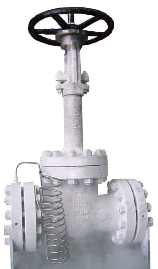
Extended Bonnet Bolted or integral vapour space extended bonnet of sufficient length to keep stem packing out of the cold zone and free of ice formation.
Austenitic Stainless Steel Forgings or Castings Tough at cryogenic temperatures and can be classed as a ‘cryogenic steel’ with good impact strength and corrosion resistance.
Shell and Trim Parts are all austenitic stainless steel and sub-zero treated in LN.
Insulation Collar / Drip Plate A ‘welded’ insulation collar/drip plate or a ‘clamped on’ insulation collar/drip plate can be provided on request.
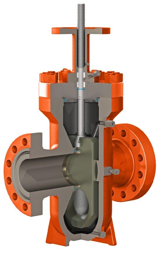
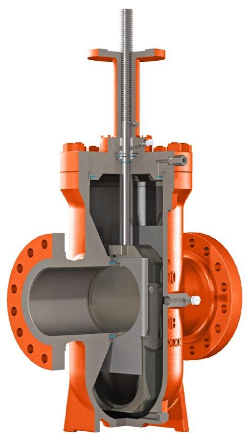
Through conduit Full bore
The through conduit opening design provides full flow passage and allows for the smooth passing of pipeline pigs. Pressure drop through the valve is no greater than that through an equal length of equal diameter pipe.
External pressure relief system for cavity over pressure protection
Due to the double tight sealing isolation design for expanding gate valve, cavity pressure can increase significantly through thermal expansion of fluid in the cavity. A body cavity thermal relief system can be provided to relieve this excess body cavity pressure.
In Line repairable
The top entry design allows for access to all internal parts if maintenance is required with the valve still in the pipeline.
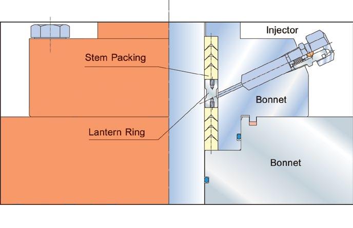
Ease of on-line stem packing maintenance
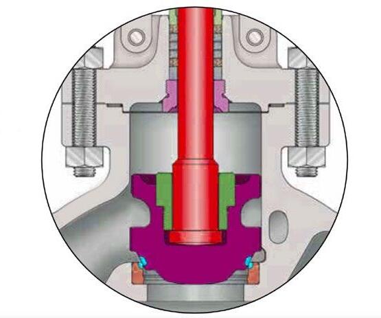
Top and bottom Chevron PTFE packing + lantern ring is the standard stem seal equipped with a stem injector with integrated check valve. Injectable packing material can be injected directly into the packing box through the injector to enhance stem sealing while the valve is under pressure.
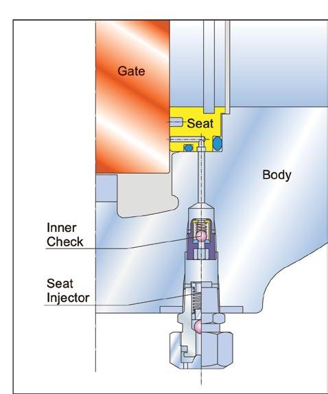
Emergency sealant injection on seats
Provision of seat injectors with integrated check valve provides emergency backup sealing. Additionally, an inner check valve is installed in front of the seat injector to prevent blow out in case of wrong operation. If a seal surface is damaged by foreign matter, valve leakage can be eliminated by using a sealant injected into a specially designed groove in the seat ring assembly. This secondary seat sealant injection backup provides a peace of mind to users who demand reliable block valve service until the valve can be properly serviced. Seats may be lubricated by injecting lubricant to enhance service life and reduce operating torque.

Australian Pipeline Valve don’t consider in our design the following factors of risk
1. Australian Pipeline Valve ‘Standard’ valves can be used in a temperature range between -29 to +490°C. (Note, pressure limitations apply above 38°C refer to Pressure/Temperature charts.) For service temperatures below -29°C valves construction materials shall be submitted to an impact test at the minimum service temperature. For temperatures above and below the standard range, special seals need to be specified by the client.
2. The onus is on the customer to specify all materials of construction and service conditions. Australian Pipeline Valve shall assume standard materials and conditions if not otherwise specified.
3. Australian Pipeline Valve ‘Standard’ valves are not equipped with devices suitable to avoid internal over-pressures caused by incorrect operations of process or by-fluids & liquids subjected to an increase of volume and/or pressure (these devices, such as the over-pressure hole in the gate or safety seats are available upon request).
4. Australian Pipeline Valve ‘Standard’ valves are not designed with special devices to withstand a sudden thermal jump (thermal shock).
5. In general Australian Pipeline Valve ‘Standard’ valves are not mechanically designed to bear overloads due to exceptional atmospheric or natural phenomenon’s (such as earthquakes).
6. In general Australian Pipeline Valve ‘Standard’ valves are not designed to bear loads on flanges, on pipe connections or pipe-line.
7. In general Australian Pipeline Valve ‘Standard’ valves can’t withstand ice inside their bodies (in this case the user has to consider the optional stem extension for insulating, avoiding the presence of residual product inside the valve).
8. Australian Pipeline Valve ‘Standard’ valves are not suitable for low temperature service below -29°C (-20°F) unless supplied (in a suitable body material) with cryogenic stem extension and other modifications, (available on request).
9. Australian Pipeline Valve ‘Standard’ valves are suitable for ‘industrial’ oxygen (not medical) service when supplied degreased and packed in polyethylene bags only.
10. The compatibility between the valves construction materials and medium is selected by the user. The user is ultimately responsible for verifying the compatibility between medium and materials.
11. Abrasive or dirty service applications need to be considered and stated at time of order.
Before installing the valve onto the pipe-line it is mandatory, for the user, to verify the compatibility of the valve with service conditions (medium, temperature and pressure). With reference to standard valves held in stock, the reseller and end user will have to assure themselves of the compatibility between the valve and the conditions required by the customer. Australian Pipeline Valve gate valves must be only used for on-off (fully open/fully closed) service.
Before using the valve in a potential explosive atmosphere it’s necessary for the customer to -
• To verify the correct type of valve and operator is specified.
• To verify the compatibility between the valve and the zone in which the valve should be installed
• To foresee the pipe-line ground condition on which the valve should be installed
• To check that the temperature if the valve surface is not higher than the flammable point of the atmosphere in which the valve is installed (in this case specify an insulating cover device for the valve and an extension for the operator)
• To avoid mechanical knocks during the installation that may cause sparks.
Australian Pipeline Valve cannot be held responsible for damage caused by use of the product for any reason, especially if it is improper use or modified.
“Australian Pipeline Valve produces isolation, control and flow reversal protection products for severe and critical service media in utility, steam, pipelines, oil & gas and process industries. APV valves and pipeline products form the most competitive portfolio in the market.”