Sulfuric Acid






Dear Friends,
Welcome to the Fall/Winter 2025 issue of Sulfuric Acid Today magazine. We are committed to bringing you the latest products and technologies impacting our industry, and we hope you find this issue both helpful and informative.
Inside, you’ll find several insightful articles covering cutting-edge technology and major projects.
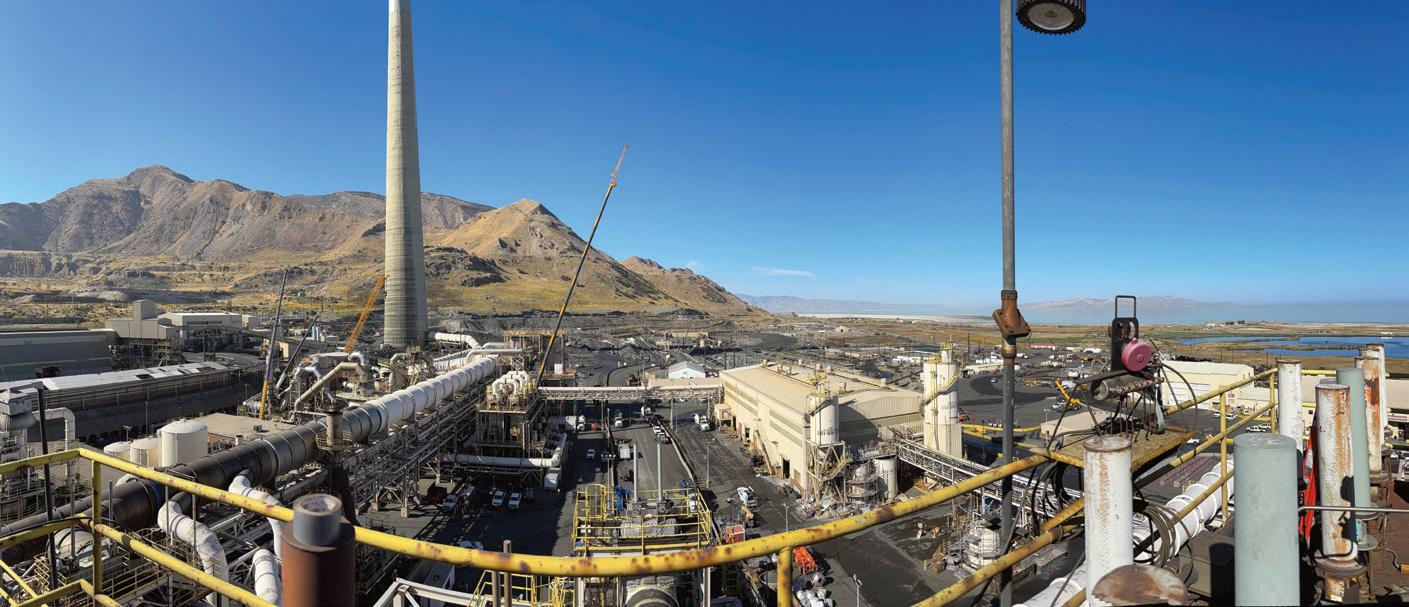
Our cover story highlights Rio Tinto Kennecott (RTK), which recently upgraded its sulfuric acid plant’s hot gas exchanger with a new design built to withstand the extremely high gas temperatures from its Magna, UT smelter (page 7).
Acuity Commodities also examines how limited supplies of copper and zinc concentrates are disrupting the sulfuric acid market, since most globally traded acid is produced as a by-product from smelters dependent on these concentrates. This challenge is forecast to persist through 2026, impacting smelter operations and global acid sales (page 10).
Elessent Clean Technologies revisits the issue of scaling in stainless steel sulfuric acid equipment (page 14).
Weir remains a trusted supplier of gate, globe, and butterfly valves engineered specifically for high-temperature, high-concentration sulfuric acid production (page 16).
INTEREP addresses why most failures in sulfuric acid plants occur during startup and shutdown, periods of higher stress and unpredictability (page 19).
CG Thermal focuses on adiabatic gas coolers, explaining how spraying water reduces SOx-laden gas temperatures, but also introduces gases into a very corrosive temperature zone. This article covers how

corrosion-resistant alloys and replaceable-design equipment are used to combat metal degradation (page 20).
Sulphurnet explains how proper dosing of lime in sulfur melting plants is critical, though its importance is often underestimated (page 22).
Beltran discusses Wet Electrostatic Precipitators (WESPs), which efficiently remove fine particles and mists while minimizing pressure loss (page 24).
Clark Solutions shares Computational Fluid Dynamics (CFD) details, explaining how engineers can analyze equipment flow without physical changes (page 26).
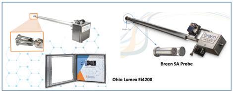
Ohio Lumex acquired the Breen SA Probe in 2023, enhanced its dew point monitoring design, and launched the improved Ei4200 Dew Point Monitor in 2024 for broader industrial use (page 28).
We are pleased to welcome our new and returning Sulfuric Acid Today advertisers and contributors, including: Academia.Holtec, Acid Piping Technology Inc., Acuity Commodities, Alphatherm, BASF, Beltran Technologies, Central Maintenance & Welding, CG Thermal, Chemetics, Christy Catalytics, Clark Solutions, Elessent MECS Technologies, INTEREP, Mercad Equipment Inc., NORAM Engineering & Constructors, Ohio Lumex, Southwest Refractory of Texas, Sulphurnet, VIP International, and Weir.
We are now assembling content for our Spring/Summer 2026 issue. If you have article suggestions or other contributions, please email me at kathy@h2so4today.com. I look forward to hearing from you.
Sincerely,
Kathy Hayward

ST. LOUIS—Elessent Clean Technologies (Elessent) is proud to announce the acquisition of Sulphurnet, a leading provider of advanced filtration solutions based in the Netherlands. This investment supports Elessent’s mission to deliver comprehensive, innovative technologies that support cleaner, more efficient industrial processes worldwide.
Sulphurnet , a leading provider of sulfur processing technology as well as advanced filtration solutions, delivers outstanding impurity removal from sulfur feed streams—a critical process for optimizing sulfuric acid production by ensuring reliability and maximizing uptime. With a versatile lineup tailored to various operational needs, Sulphurnet’s offerings naturally enhance Elessent’s capabilities across the sulfuric acid, chemical, chlorine, and green hydrogen sectors.
“We are thrilled to welcome Sulphurnet to the Elessent family,” said Eli Ben-Shoshan, CEO, Elessent Clean Technologies. “This acquisition is a natural fit for both companies. It enhances our ability to serve our customers with a broader range of high-performance technologies and strengthens our global presence in key markets.”
The acquisition is effective immediately, and integration efforts are underway to ensure a seamless transition for custom-
ers and partners.
Elessent Clean Technologies is a global leader in process technologies to drive sustainability and carbon neutrality in the metal, fertilizer, chemical and oil refining industries with an unwavering commitment to customer support. We provide extensive global expertise across our portfolio of offerings in key applications–MECS® sulfuric acid production, STRATCO® alkylation, BELCO® wet scrubbing and IsoTherming® hydroprocessing.
Offering critical process equipment, products, technology and services, we enable an array of industrial markets, including phosphate fertilizer, non-ferrous metals, oil refining, petrochemicals and chemicals, to minimize their environmental impact and optimize productivity. We are dedicated to helping our customers produce high-quality products used in everyday life in the safest, most environmentally-sound way possible, with a vision to make the world a better place by creating clean alternatives to traditional industrial processes.
For more information, visit www. ElessentCT.com.
ODISHA, India—Paradeep Phosphates has successfully commissioned its 1500


MTPD sulfuric acid plant D at its Paradeep plant in Odisha. The commissioning of this plant will enhance the company’s captive production of sulfuric acid, ensures the availability of a key raw material for manufacturing phosphoric acid and fertilizers, thereby reducing dependency on import and improving operational efficiency.
Total expenditure incurred for the project is around Rs 510 crore as of commencement of commercial production.
Paradeep Phosphates is primarily engaged in manufacturing, distribution, trading and sales of a variety of complex fertilizers such as DAP, several grades of NPK, zypmite and its by-product, phospho-gypsum, and HFSA.
For more information, visit www. paradeepphosphates.com.
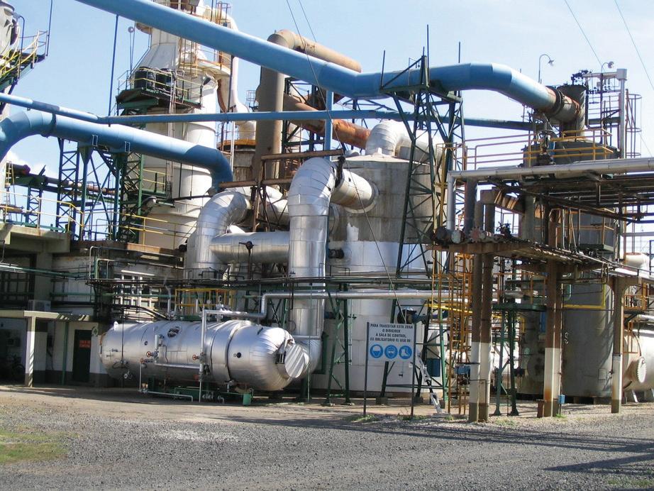
DARMSTADT, Germany—With the successful commissioning of a new sulfuric acid plant in Worms, Germany, Röhm GmbH, based in Darmstadt, has further reinforced its global production network. As the company’s largest production site, Worms plays a strategically pivotal role in the global network.
excellent occupational safety record. “The fact that we were able to implement the new plant not only on time and within budget, but also in accordance with the highest safety and quality standards, is an outstanding achievement,” emphasized COO Hans-Peter Hauck. “My thanks go to the project team and all the colleagues involved—your commitment and expertise are exemplary for what makes our Worms site special: high-performance production, innovative research, and a strong team.”
For more information, visit www. roehm.com/en.
SANDTON, South Africa—Vedanta Zinc International has announced plans to bring the sulfuric acid plant at the Skorpion Zinc Mine and Refinery back into production, with recommissioning scheduled for completion within the next four to six months.
The announcement marks the first significant development at Skorpion since the mine was placed on care and maintenance in 2020.
Röhm is the only global manufacturer of methyl methacrylate (MMA) and polymethyl methacrylate (PMMA) with production sites in Europe, Asia, and North America. In recent years, Röhm had already made targeted investments to strengthen this unique position, including significantly expanding PMMA production capacities and constructing a stateof-the-art innovation center at the Worms site. Last year, the company commissioned a new plexiglass plant in Worms.
Now, after one and a half years of construction, the sulfuric acid plant has been put into operation. Equipped with state-ofthe-art technology, it sets new standards in efficiency and makes a significant contribution to strengthening the regional supply of MMA. The plant replaces the previous facility, which was damaged by a fire at the end of 2023. Sulfuric acid is a key precursor for the production of MMA–an important basic chemical for customers in the automotive, construction, and medical technology industries and PMMA.
“With the new sulfuric acid plant, we are not only increasing supply security for our customers, but also strengthening our value chain in the long term,” said COO Hans-Peter Hauck at the inauguration ceremony. The construction project exemplifies Röhm’s integrated production principle, which focuses on producing in the region for the region. In doing so, Röhm offers its customers not only regional proximity but also a high degree of delivery reliability
The project also stands out for its
The sulfuric acid plant, originally constructed in the early 2000s, is an integral part of Skorpion’s zinc refinery complex located near Rosh Pinah in southern Namibia. Its role is to capture sulfur dioxide gases released during the roasting of zinc ore and convert them into sulfuric acid.
By restarting the plant, Vedanta will not only reduce harmful emissions but also produce a high-value industrial product that has significant demand in Namibia and across the region.
Once operational, the refurbished facility is expected to produce approximately 1,000 tonnes of sulfuric acid per day at a concentration of 98%, making it suitable for a wide range of industrial and metallurgical applications.
This scale of production will re-establish Skorpion as an essential supplier of acid to Namibian industries and to regional markets.
By capturing sulfur dioxide emissions and converting it into a usable product, the company will minimize atmospheric pollution and support Namibia’s broader ecological commitments.
At the same time, the production of sulfuric acid will generate revenues and potentially create employment opportunities for skilled workers during the refurbishment and operational phases.
Vedanta noted that it has already issued a call for Expressions of Interest from companies interested in long-term off-take agreements.
These agreements will cover both the supply of sulfuric acid and the logistics arrangements required to move product from the Skorpion site to customers.
Deliveries will be made on an exworks basis, which places responsibility for transport and distribution on the buyer once the product leaves the plant.
“The initiative reflects our commitment to building strategic partnerships that create sustainable value. We invite companies with the required technical and logistical capabilities to submit their interest in entering into a longterm off-take agreement for the supply of sulfuric acid,” Vedanta Zinc International said in a statement.
Vedanta Zinc International, a subsidiary of Vedanta Limited with a market capitalisation of around $30 billion, manages a portfolio of zinc assets in southern Africa. These include producing mines in South Africa’s Northern Cape as well as the Skorpion operation in Namibia, which has remained dormant since open-pit reserves were depleted and technical challenges emerged in processing zinc-oxide ore.
Although full-scale mining at Skorpion has not resumed, Vedanta has sought to maintain its presence in Namibia through strategic investments and infrastructure management.
The decision to restart the acid plant is seen as part of a broader effort to keep the site active while the company evaluates long-term options for zinc mining and refining in the country.
For more information, visit www. vedanta-zincinternational.com.
VANCOUVER—Marimaca Copper Corp. has entered into an agreement to acquire a used sulfuric acid plant in Chile from CEMIN Holding Minero, aiming to reduce its exposure to the volatile acid market and lower production costs. This strategic move is expected to cut sulfuric acid costs by approximately 30%, significantly mitigating financial risks and enhancing profitability for the Marimaca Oxide Deposit. The acquisition will allow Marimaca to produce up to 150ktpa of sulfuric acid, covering 30-40% of its total consumption, and offers a substantial opportunity for cost optimization in its operations.
Marimaca Copper faces significant financial and operational challenges, primarily due to being in a pre-revenue stage with negative income and reliance on external financing. Despite these hurdles, recent corporate developments, such as exploration successes and strategic expansions,
offer potential for future improvement. Technical indicators suggest caution due to mixed signals, while valuation remains a concern due to current financial instability.
Marimaca Copper Corp. operates in the mining industry, focusing primarily on copper production. The company is engaged in developing the Marimaca Oxide Deposit in Chile, which is a significant project for copper extraction. Marimaca aims to optimize its operations by managing key input costs, such as sulfuric acid, which is crucial for its heap leach operations.
For more information, visit www. marimaca.com.
HAMBURG—Aurubis, a leading global provider of non-ferrous metals and one of the largest copper recyclers worldwide, has wrapped up the largest scheduled maintenance shutdown at its Bulgarian plant in three decades on schedule. Following this achievement, all facilities at the site have resumed full operations. Over approximately two months, 120 coordinated projects were executed on schedule and within budget. The nearly €115 million investment helps secure the Bulgarian plant’s strong operational performance for the foreseeable future.
Thanks to major investments in advanced plant technology along with numerous digitalization and automation initiatives during past shutdowns, Aurubis has achieved a substantially higher level of efficiency and stability in production. Building on this stable foundation, the company is set to extend the interval between future planned maintenance shutdowns from two to three years.
“Successfully completing such a largescale project in just around two months is a clear testament to our capabilities— Aurubis can execute complex projects safely and reliably. This is a strategic investment in the long-term viability of the site, which is a vital pillar in the group,” said Tim Kurth, COO Custom Smelting and Products and Executive Director, Aurubis, Bulgaria. “Our site in Bulgaria has earned recognition for maintaining peak plant availability in the past. We have now laid the groundwork to uphold that standard while also extending the time between maintenance cycles.”
For more information, visit www. aurubis.com/en. q


By Acid Piping Technology, Inc.
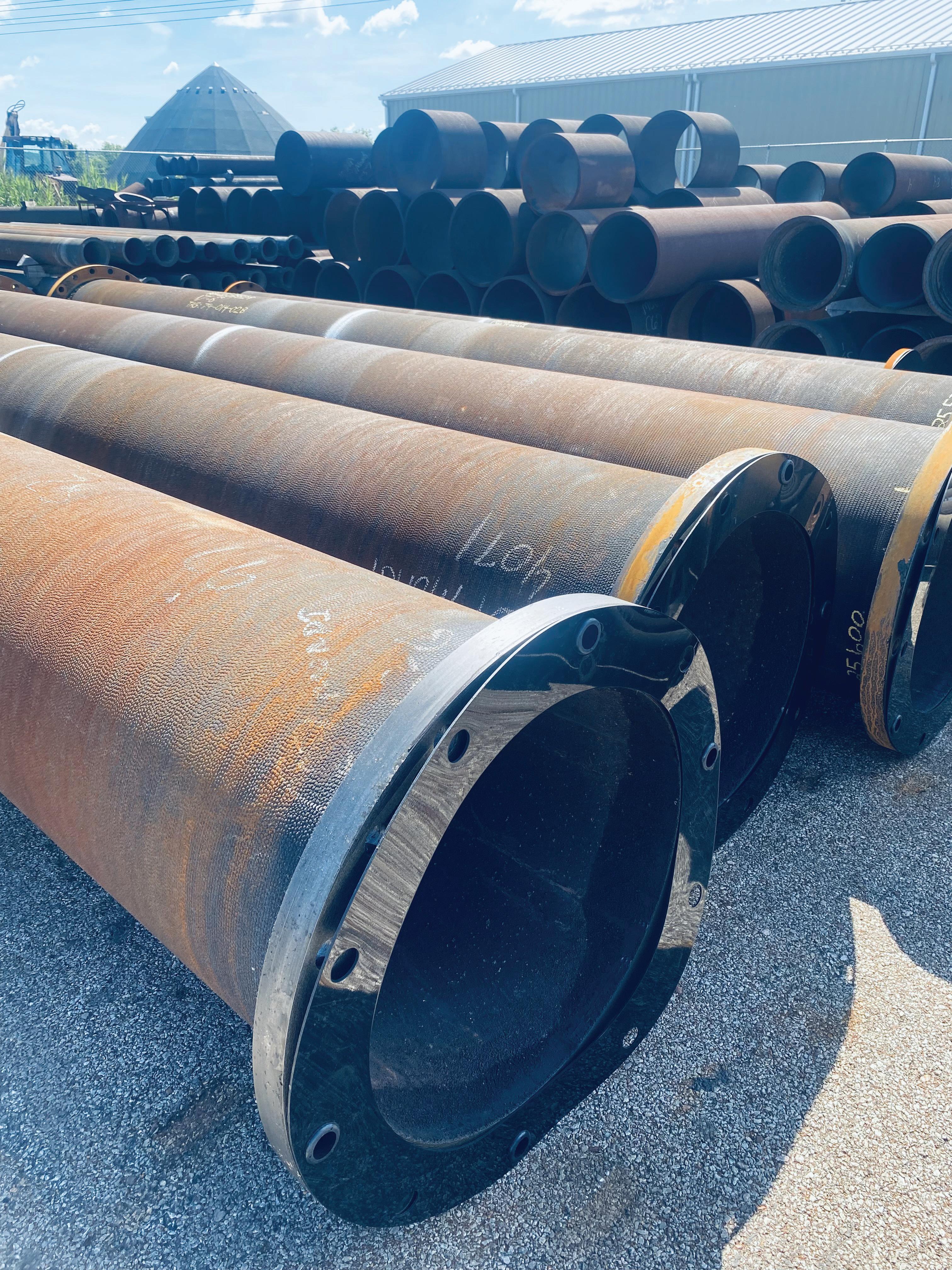
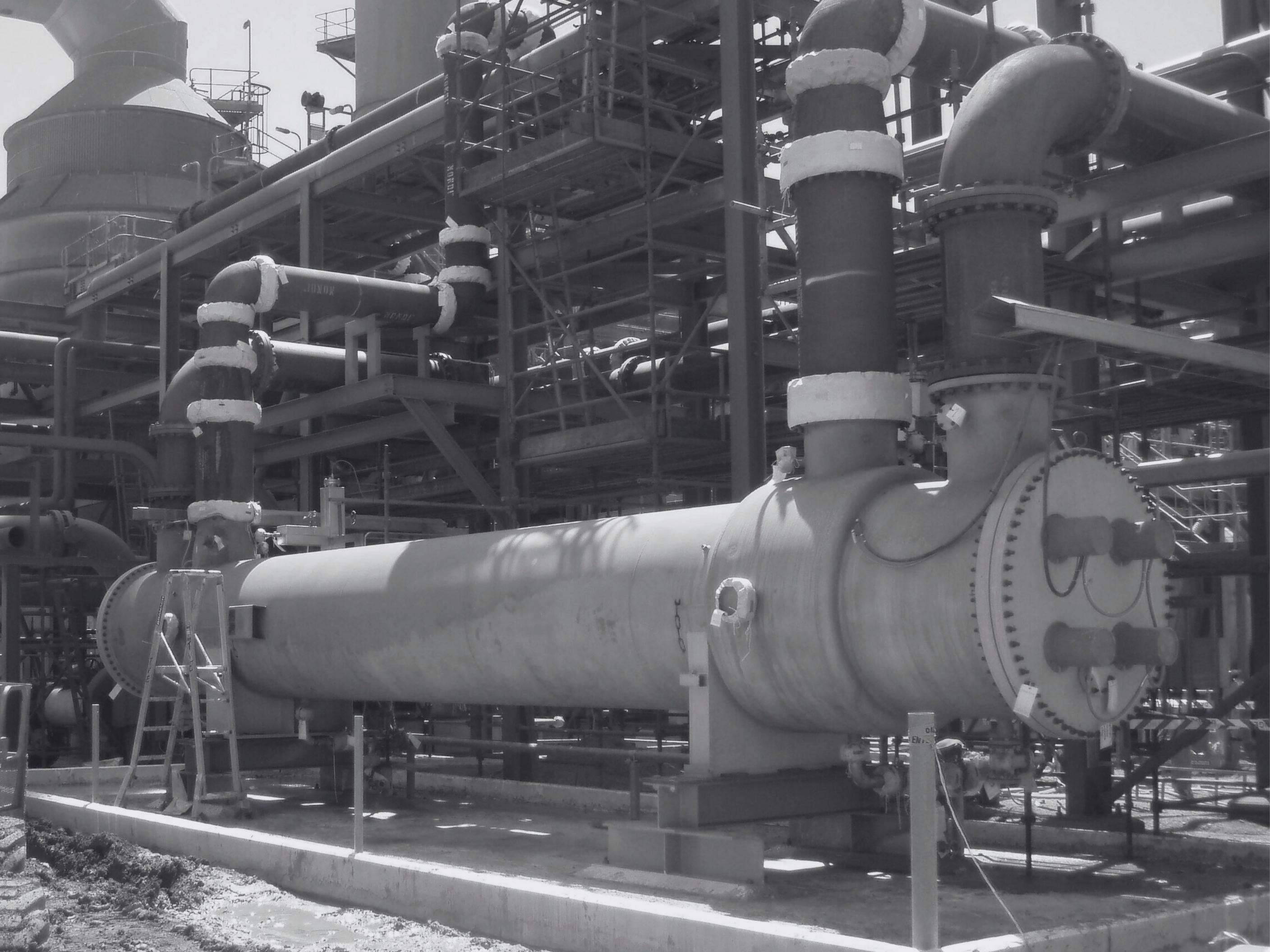
SINCE 1991, ACID PIPING TECHNOLOGY, INC. HAS BEEN THE WORLD LEADER IN RELIABLE AND COST‐EFFECTIVE PRODUCTS FOR THE SULFURIC ACID INDUSTRY. MONDI™ PIPING WAS SPECIFICALLY DESIGNED FOR 30+ YEARS OF CONTINUOUS SERVICE IN HIGH CONCENTRATION SULFURIC ACID AT A FRACTION OF THE COST OF OTHERPIPING SYSTEMS. LEARN MORE ABOUT HOW MONDI™ PIPING CAN BENEFIT YOUR OPERATION AT WWW.ACIDPIPING.COM. CUT THE COST. INCREASE THE DEPENDABILITY.
By: April Smith, Editor
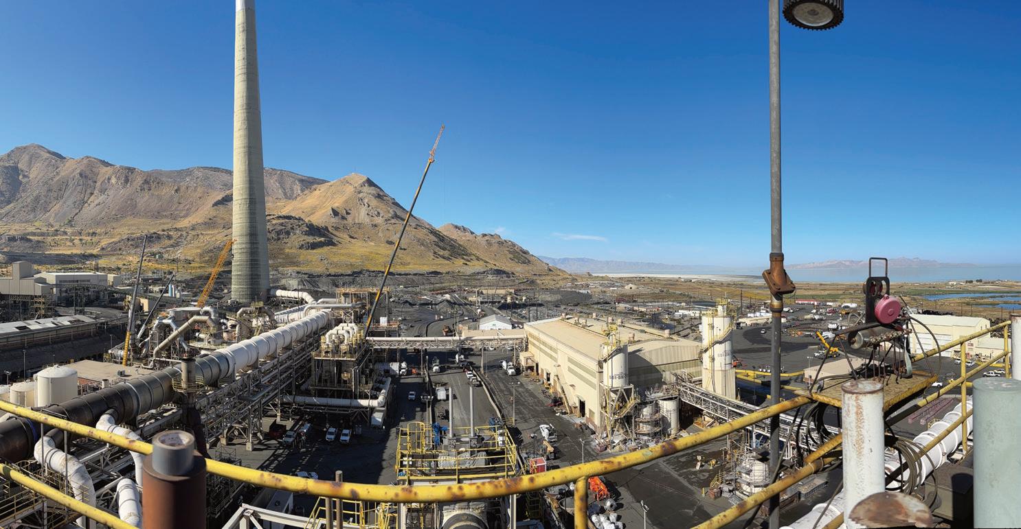
Prominent copper producer Rio Tinto Kennecott (RTK) recently replaced its sulfuric acid plant’s hot gas exchanger for a new design capable of withstanding the very high gas temperatures from the company’s smelter in Magna, UT. Variable gas strength originating from the smelter had been exposing the company’s old exchanger to gas temperatures above its design threshold causing tube failures.
An inspection conducted in 2023 showed that 10% of the existing exchanger’s tubes were plugged and another 5% of the tubes were experiencing thinning walls. “We were at risk of limiting throughput, so we elected to replace the unit to maintain both capacity and environmental requirements,” said Scott King, Superintendent of Feed & Byproducts Engineering, RTK.
The new exchanger, designed and supplied by NORAM Engineering and Constructors Ltd., mitigates the effects of high temperatures on gas-to-gas heat exchangers. To provide an appropriate replacement, NORAM used advanced analytical techniques, such as computational fluid dynamics (CFD), to identify the issues RTK was experiencing with its existing exchanger.
RTK is a subsidiary of Rio Tinto, one of the world’s leading metals and mining companies with a global workforce of over 49,000 and operating assets in Australia, Asia, North and South America, Europe, and Africa. Rio Tinto produces iron ore, aluminum, copper, gold, silver, molyb -
“It took close coordination with contracting partners, maintenance, projects and operations but completed ahead of schedule and most importantly, safely and without incident.” “ ”
denum, tellurium, selenium, diamonds, and industrial minerals. Many of these materials are used in low-carbon transition applications.
RTK’s operation, located just outside Salt Lake City, mines and processes minerals from the Bingham Canyon Mine. The mine, which has been in operation since 1903, is currently one of the top producing mines in the world. The site includes a concentrator, smelter, refinery, and tailings storage facility.
RTK is also one of the largest producers of sulfuric acid in the United States, about 900,000 short tons per year. Its customer base includes industries in fertilizer manufacturing, paper processing, as well as copper leaching.
Sulfuric acid is manufactured as a by-product of the
company’s copper production process. Copper-sulfide ore from the Bingham Canyon Mine is processed in the smelter generating gaseous sulfur dioxide, which is captured and converted into highly concentrated sulfuric acid.
At RTK, and copper plants generally, the smelting of copper ore produces large volumes of off-gas rich in sulfur dioxide (SO2). During the creation of sulfuric acid, the process of converting SO2 to SO3 through the converter’s catalyst beds cause exothermic reactions that require a series of gas-to-gas heat exchangers to manage the gas temperature between different process stages to ensure optimal conversion efficiency.
“The amount of heat released in a conversion stage depends on the concentration of SO2 in the gas stream entering the acid plant. The higher the SO2 concentration, the more heat is released, resulting in higher gas temperatures. This effect is most prominent in the first catalyst bed, where the SO2 concentration is highest,” explained Werner Vorster, Area Business Manager, NORAM.
The composition of the SO2-rich gas leaving the smelter and entering the first catalyst bed often fluctuates because of variations in furnace operation and concentrate quality. The result is higher-than-expected gas concentrations entering the downstream acid plant.
“In this environment, operators have limited time to
react to concentration excursions and may not be able to adequately dilute the incoming SO2-gas stream if the flows are too high,” said Neal Londry, Senior Process Engineer, NORAM. “SO2 concentrations greater than 14% (by volume) can cause gas temperatures leaving the first converter pass to be greater than 650°C (1,200°F), which is significantly hotter than typical peak temperatures seen in sulfuric acid plants [1],” he said.
Because the hot gas exchanger lies immediately downstream of the first converter pass, it is essential equipment in managing the plant’s overall temperature profile and is routinely exposed to very high gas temperatures. “The combined effects of hot gas corrosion and excessive thermal stress on the exchanger tubes makes for one of the most severe service cases seen in sulfuric acid plants,” said Londry.
RTK conducts regular eddy current tube inspections

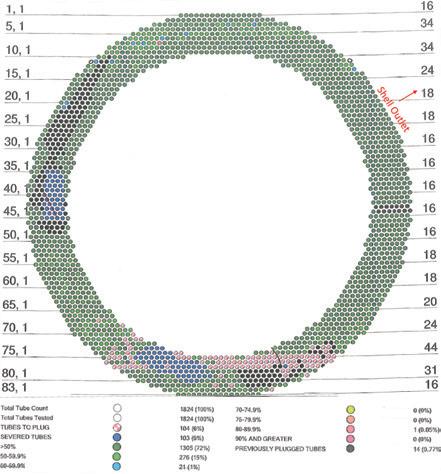
of its hot gas exchanger as part of its preventative maintenance program. A recent tube inspection map (Fig. 2) shows most of the tube failures were located immediately above the bottom tubesheet and were a result of thinnedout tube walls caused by mechanical stress from thermal movement of the bottom tubesheet.
“The inspection showed the failures were limited to two major regions of the tube bundle, in areas that are roughly symmetrical across the axis of the shell outlet nozzle,” Vorster explained.
Prior to designing the replacement exchanger, NORAM evaluated the operating environment at RTK’s sulfuric acid plant. In its analysis, it was determined that to increase the lifespan of the replacement hot heat exchanger the new design should accomplish two goals:
1. Reduce the tube metal temperatures in the hottest regions of the exchanger as much as possible.
2. Mitigate the effects of very high temperatures, particularly on the tubes.
NORAM reasoned that the symmetrical pattern of tube failures seen in Fig. 2 indicated poor gas flow distribution in the exchanger shell through the tube bundle.
“It appeared that the tube wall corrosion was caused by disproportionate heating from the hot gas inside the tube and inadequate cooling from the lower temperature gas flowing through the exchanger’s shell,” said Londry.
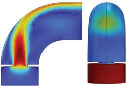
To confirm the flow distribution hypothesis, NORAM generated a CFD model of the hot gas exchanger to map the expected shell-side gas temperature above the bottom tubesheet under normal operating conditions. The model uses a porous region with Darcy-Forcheimer flow resistance coefficients [2] calibrated to match the shellside pressure drop of the existing exchanger.
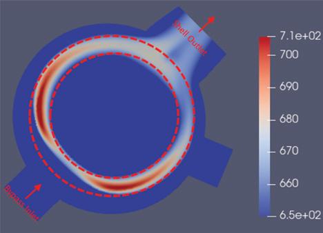
“The outcome of the simulation (Fig. 3) shows a direct overlap between regions of peak temperature in the shellside gas and the regions of tube failures (Fig. 2),” Londry said.
outside the tube bundle to a bypass nozzle at the bottom of the exchanger shell. But the feature had unintended consequences in RTK’s particular service case.
“Our CFD model showed that an unintended sideeffect of the internal bypass layout is that, at high bypass flowrates, the bypassed gas directly impinges on the tube bundle where it first enters the exchanger, creating resistance against the regular shell gas flow through the tube bundle in the region nearest the bypass nozzle, biasing the shell gas towards the section of the bundle opposite the bypass nozzle,” Londry said.
So, to lower the tube metal temperature during normal operation, NORAM determined that the replacement exchanger would require modifications to reduce the amount of gas needing to be bypassed.
“To improve the gas distribution, we looked at the heat exchanger design, specifically regarding the amount of excess heat exchange area. Typically, heat exchangers are designed with more heat transfer area than is actually required during normal plant operation, called the Safety Factor. To ensure adequate performance even in the case of significant process disruptions, the existing heat exchanger was sized with 20% excess area,” Londry said.
But in analyzing RTK’s historical plant data, NORAM determined that, during normal operation, more than 30% of the shell-side gas was being bypassed around the tube bundle. “We also found that the plant had never in its history experienced a process upset that required that 20% excess heat exchange area,” Vorster said.
NORAM and RTK discussed these findings and agreed to reduce the number of tubes in the replacement exchanger targeting an excess area of only 10%, which reduced the amount of gas bypass during normal operation by approximately one third.
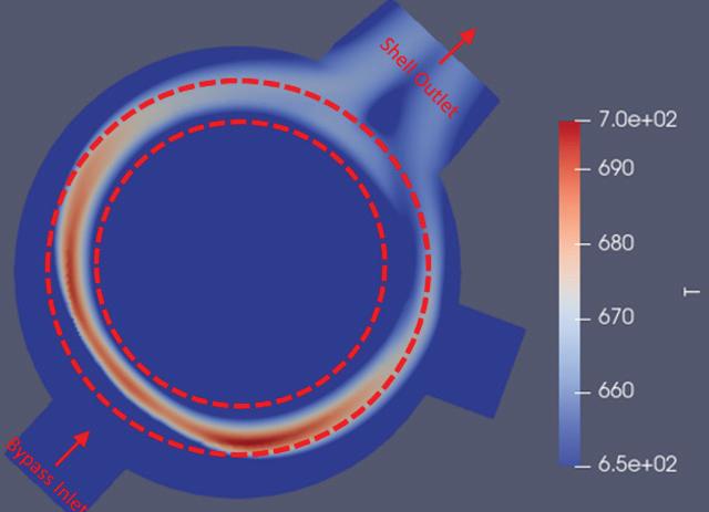
CFD modelling indicated that this reduction in shellside bypass would significantly improve gas distribution through the tube bundle, as seen in Fig. 4, thereby reducing the peak temperature in the problematic regions by approximately 15°C, on average.
NORAM determined that the flow issue was caused by the internal bypass feature in the existing hot heat exchanger. This shell side gas bypass (labelled ‘Bypass Inlet’ in Fig. 3) controls the outlet temperatures from the exchanger by diverting a portion of the shell side inlet gas
“This is a significant reduction,” said Vorster, “because the rate of chemical reactions, including corrosion, is typically reduced by half for every 10°C reduction in temperature, according to the Arrhenius Equation [3]. Reducing the heat exchange area is the single most significant modification made to the replacement unit in terms of extending its service life,” he said.
Although the design changes reduced tube metal temperature in the problematic regions, very high temperatures are still a reality that can’t be completely prevented. So NORAM also incorporated these additional design features to reduce the effects of hot corrosion and thermal stresses:
• Tube thickness was increased from 14 to 12 BWG, lowering the operating stress in the tubes and increasing their corrosion allowance.
• Tubesheet thicknesses were increased, particularly that of the bottom tubesheet. A thicker bottom tubesheet will better resist deflection due to thermal growth, reducing the stress applied to the bottom of the tubes.
• The shell outlet nozzle size was increased to the greatest extent possible. CFD analysis indicated that increasing shell nozzle sizes further improved gas distribution in the shell.
NORAM designed, fabricated, and delivered the replacement exchanger, which is expected to come online this fall. Table 1 compares key parameters of the existing and replacement exchangers.
Because the significant volume of off-gas from the smelter results in very large equipment, it is generally impractical to ship exchangers in one piece. However, because of the reductions in excess heat transfer area and shell diameter, the replacement exchanger could shipped to the plant by road.
The advantage was that the unit could be built in the more readily controlled environment of the fabrication shop,
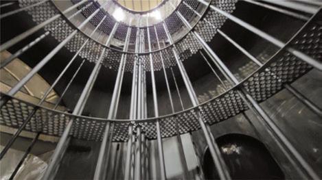
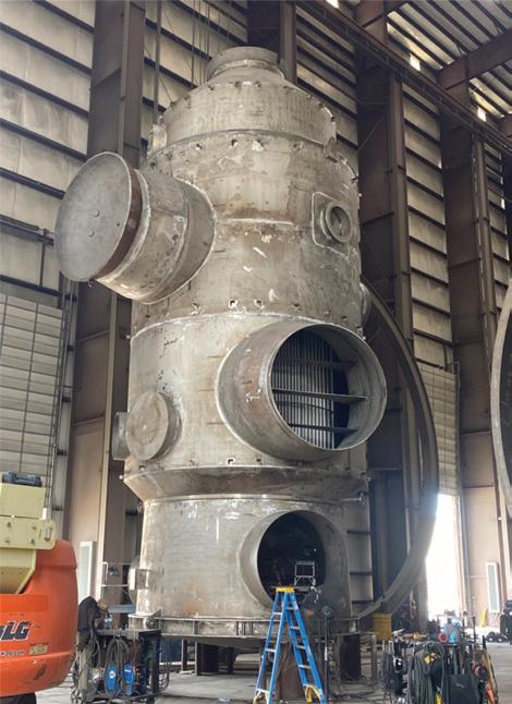
which improves overall quality and reduces fabrication time. Plus, shop fabrication translates to less congestion at the plant site and fewer safety risks to plant personnel.
However, the exchanger is still quite large and created challenges for road transport, especially given the distance of 1,600 miles from fabricator to plant.
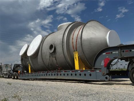
“This was more of a challenge than expected due to all the state DOT permitting issues and road construction projects constantly evolving over the summer months,” said King. “But we liked the quality control of it being built in a shop,” he said.
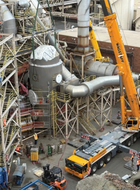
The plant also encountered the usual challenges of concurrent work happening in limited space, King said. Along with the exchanger, the hot interpass heat exchanger and the crossflow SO2 stripper were being replaced.
“The hot interpass was approaching the 10% threshold in 2023 and we felt it would be over 10% in 2025 and wanted to maintain throughput and efficiency. The brick-lined crossflow stripper had numerous patches over the past few years so we decided to replace it with an alloy tower for asset integrity reasons,” King explained.
Despite three major pieces of equipment being staged and moved within a tight space, all three vessels were lifted into place without issue.
“It took close coordination with contracting partners, maintenance, projects and operations but completed ahead of schedule and most importantly, safely and without incident,” said King. q
References
1. Louie D (2014) Contact Section. In: Louie D Handbook of sulphuric acid manufacturing, 2nd edn. DKL Engineering, Inc., Ontario, p. 3-1 – 3-88
2. Hafsteinsson HE (2009) Porous media in OpenFOAM. https://www.tfd.chalmers.se/~hani/kurser/OS_ CFD_2008/HaukurElvarHafsteinsson/haukurReport.pdf. Accessed 03 Apr 2025
3. Arrhenius SA (1889) Über die Dissociationswärme und den Einfluß der Temperatur auf den Dissociationsgrad der Elektrolyte, Z Phys Chem 4: 96-116
4. Neal Londry, P.Eng.; Werner Vorster, PhD, P.Eng. (2025, Nov. 16-20) Smelter Acid Plant - Replacement Hot Gas Exchanger Case Study, Copper 2025, Phoenix, AZ USA.
By: Fiona Boyd and Freda Gordon, Directors of Acuity Commodities
In our article in the Spring/Summer issue of Sulfuric Acid Today, we discussed how a tight base metal concentrate supply market, notably copper and zinc, was contributing to uncertainty overhanging the sulfuric acid market. This is because most acid that feeds global merchant acid demand, rather than captive consumption, is a by-product from base metals smelting relying on concentrate supply. As we look ahead to 2026, this will remain a critical issue that will impact not only smelter run rates but also sales strategies for byproduct sulfuric acid output.
When concentrate availability is tight, smelters reduce treatment charges (TC) and refining charges (RC) to attract feedstock. While historically TC/RCs have been a source of revenue for smelters, they have been at lows this year. As a result, there continue to be efforts for smelters to look to other revenue streams, including from by-products. We expect no improvement in concentrate availability, and therefore TC/RCs for 2026, meaning again there will be emphasis on recovering revenues in other ways.
Meanwhile, other smelters have shifted to throughput curtailments to manage challenging market conditions. As an indication, Mitsubishi Materials Corporation (MMC) confirmed its decision to cut operating rates at its Onahama smelter in Japan by 25% in 2026, reducing by-product acid output. This is as plenty of newly developed base metal smelting capacity remains unused due to the tight concentrate situation.
It should also be noted Freeport McMoRan declared force majeure (FM) at its Grasberg mine in Indonesia after a mud rush in early September. The FM will reduce copper concentrate output accordingly, with its output forecast to be about 35% lower than previously planned for 2026. The reduced availability of local concentrate will constrain run rates at newly developed smelters, as well as weigh on overall concentrate availability, influencing TC/RCs in turn.
With other smelters already running at reduced rates, largely tied to concentrate market conditions, there should be a knockon effect on acid output. But, at the same time, the inelasticity of by-product smelter


acid cannot be forgotten—in that neither firmer nor weaker demand for sulfuric acid will dictate smelter output. Therefore, even with constrained smelter acid supply, merchant sulfuric acid demand has to be there to continue to provide price support.
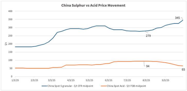
It was in late 3Q when the market saw an unusual trend—sulfur prices were trending upward while acid prices moved in the opposite direction, again despite constrained supply. As an indication, the China spot price for spot sulfur acid imports was as high as $348/t CFR going into 4Q, the highest since July 2022, and up from as low as $180/t CFR as 2025 began. Meanwhile on the acid side, China FOB spot export pricing for sulfuric acid reached as low as $60/t as 4Q began, down from as high as $96/t FOB in August.
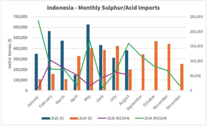
The prices moving in opposite directions can largely be tied to different demand drivers for the two raw materials. When we look at sulfur, prices have moved up mostly continuously since March 2025, largely due to strong demand. Indonesia’s strong appetite to feed new sulfur burners to sup -
port acid consumption for nickel leaching was a main driver. As seen in the graph below, its sulfur imports have increased throughout 2025. But at the same time, its demand for import by-product acid has trended down from volumes imported in 2024, arguably pressuring acid prices accordingly.
We discussed in our last article that the development of the nickel capacity in Indonesia had knock on effects for other nickel producers, namely in Australia. This included BHP putting its Nickel West operations on care and maintenance in October 2024, including the Kalgoorlie nickel smelter. With the smelter no longer running as a result, we are seeing increased import needs into Kwinana to support local consumption.
Meanwhile, at the time of writing, the market was awaiting news on the fate of Glencore’s Mount Isa smelter, following the cessation of underground copper mining operations to support throughput ceasing in July 2025 after seven decades of continuous operation. With the smelter
now dependent on third-party concentrates, it is calling into question is operational viability. Discussions with the government for a short-term support package were ongoing at the time of writing. At the same time, Dyno Nobel, which processes metallurgical gas from the smelter to support its Phosphate Hill fertilizer operations said it will shut that complex in September 2026 if no buyer can be found by the end of 1Q26. It said securing the metallurgical gas from the Glencore smelter remains critical to the future of Phosphate Hill and solutions continue to be pursued in collaboration with local governments.
While supply trends of smelter acid will continue to impact availability for consumers of sulfuric acid, we continue to see new smelter capacity entering the market, albeit on a delayed basis. This is again pressuring demand for concentrates and TC/RCs accordingly.
Moving back to sulfur, we noted in our last article that tightness of smelter acid availability was supporting the export of sulfur-based acid, which is often opportunistic based on price. One could argue this stable demand to augment smelter acid supply contributed to the firm demand for sulfur, and therefore pricing.
However, one must once again go back to demand. It was in August when we began to see Morocco’s OCP delaying or seeking to divert acid cargoes, tied to previous over purchasing activity which supported northwest European spot acid pricing at that time. So, while northwest Europe spot FOB pricing reached as high as $138/t FOB in July 2025, it had slipped to a low of $70/t FOB as 4Q commenced.
Finally, we note that during the time of our last article, US tariffs were in the forefront, with the constant back and forth resulting in what some may describe as tariff whiplash. While we recognize there are tariff implications for things such as US acid imports from offshore, discussions related to tariffs directly have largely cooled, except how it relates to overall economics.
As we look to 2026, much emphasis will remain on tight concentrate availability, namely copper, sulfur price direction, and ongoing uncertainty in the geopolitical landscape. q

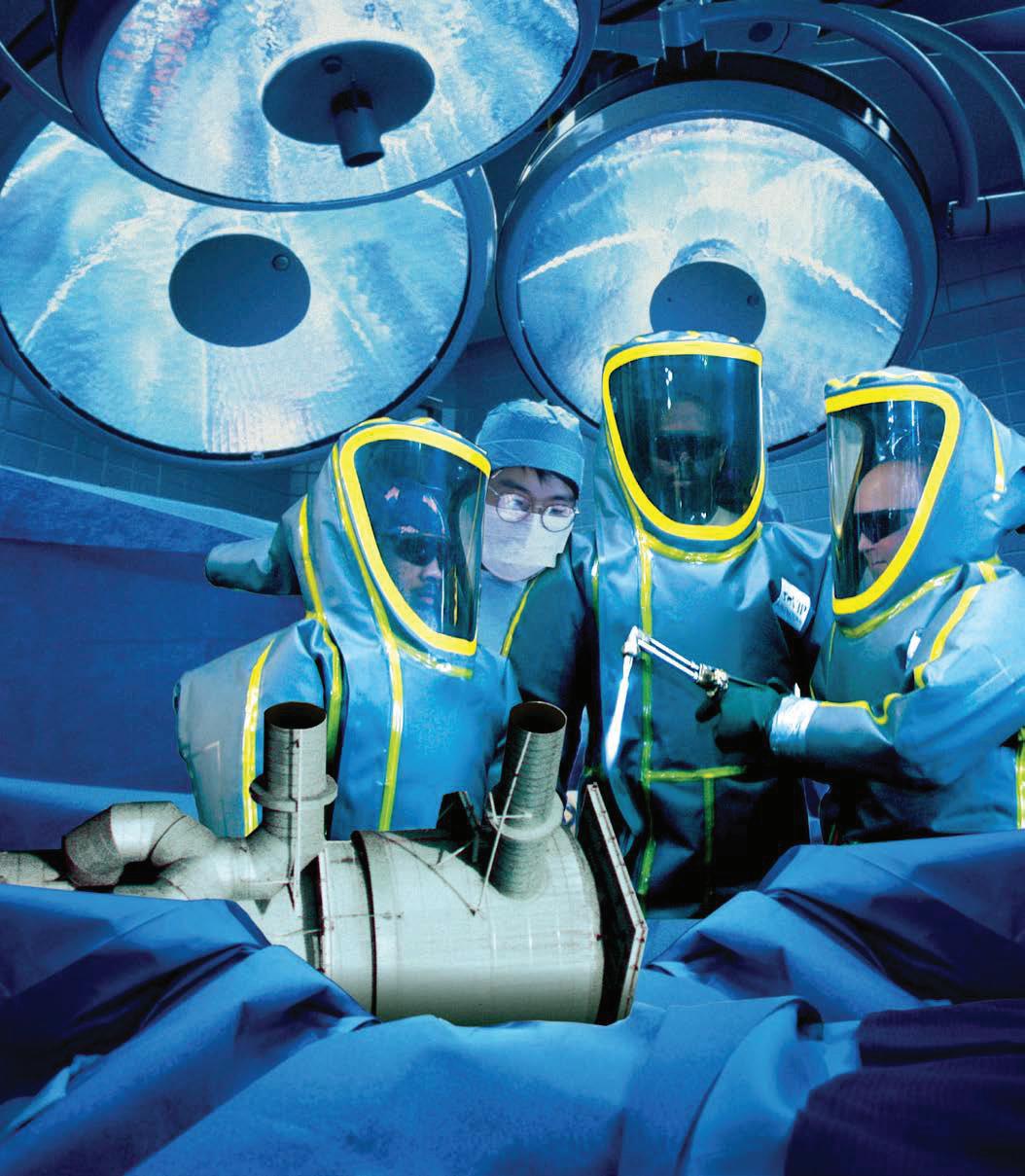


Workplace safety should be made a top priority because it protects the most valuable part of any organization: its people. Employees are a company’s most important asset because their skills, dedication, and daily efforts drive the success of the entire organization. A safe work environment has proven to reduce the risk of injuries and illnesses, ensuring that employees can perform their jobs without fear or unnecessary risk.
The framework for a safe work environment starts with compliance and thorough employee training, which are crucial to the safety and success of a company. Beyond compliance and training, a strong safety culture shows that a company values its employees, which boosts morale, employee retention, and overall safety performance.
Safety should not be treated as a one-time initiative; it should be an ongoing priority. In every industry, safety is not just a responsibility, it is a key to long term success.
Safety culture begins with upper management since leadership sets the tone for the entire organization. When management consistently prioritizes safety, it sends a clear message that the well-being of its employees comes first. By actively supporting safety programs, providing resources, and hold-
ing everyone accountable, management can create an environment where safety is not just a policy, but a shared value. When management leads by example, it encourages all employees to take safety seriously and helps to foster a culture of accountability and trust.
The framework for every company’s safety program should begin with agency compliance. Compliance with the Occupational Safety and Health Administration (OSHA) Regulations is critically important in the workplace. These regulations are designed to ensure safe and healthy working conditions for employees by enforcing standards and providing training, education, outreach, and assistance. Compliance with other relevant agencies is also extremely important. Employers should perform due diligence to determine which agencies and regulations apply. For example, the following agencies may be applicable to you depending on your specific industry: Mine Safety and Health Administration (MSHA), United States Environmental Protection Agency (EPA), or the National Institute for Occupational Safety and Health (NIOSH).
Most people have heard the statement “OSHA Regulations are written in blood.” This is a powerful statement that serves as
By: Alan Williamson, Safety Manager, CSP / VIP International
a reminder that many of the safety rules and standards enforced by OSHA exist because of real life tragedies. As an employer, you should strive to exceed these standards. Simply meeting these standards is a requirement, but choosing to exceed them shows commitment to prioritizing safety.
The key to success is preparation. Setting your employees up for success is an integral part of the company’s success as a whole. It is the employer’s responsibility to provide employees with the knowledge and training that they need to do their jobs safely and effectively. Prioritizing employee training directly influences safety, productivity, and morale of the company. In addition to basic safety principles, your company’s safety training program should be tailored to the specific work that you perform. Training should address and train employees on the particular hazards they will encounter while working. Employees should also be given the opportunity to practice and demonstrate the new skills they have learned. An ongoing comprehensive workplace safety training program can support a positive safety culture. When safety is addressed on an ongoing basis, and not just a single annual training, it becomes ingrained in the company’s cul-
CUSTOM TOWER DESIGNS TO MATCH YOUR PLANT NEEDS
• Achieves performance requirements in all plant operating modes
• Customized SARAMET® metallurgy is selected for each application (Dry, Inter, Final, ALPHA™ or Oleum Towers)
• Proprietary gas inlet nozzle designs engineered to eliminate localized corrosion
• Designed for retrofit or new tower installations
• Allows use of existing or new tower foundations minimizing installation time
• Scope of supply ranges from detailed engineering and manufacturing drawings with material supply, to complete EPC
• Full tower life cycle support is available from Worley Chemetics, including technical and inspection services
LEARN MORE chemetics.info@worley.com chemetics.equipment@worley.com
WORLEY.COM/CHEMETICS
ture. Remember, employee training is not an expense, it is an investment. Investing in your employees pays off in reduced risk, increased efficiency, and long-term success. Making workplace safety an ongoing priority is essential for protecting employees, maintaining productivity, and fostering a positive work environment. Safety should not be treated as a one-time initiative or a box to check; it must be continuously enforced and practiced at all levels of the company. By staying proactive and vigilant organizations can identify and address hazards before they lead to incidents, ensuring that every employee feels safe, valued, and empowered to speak up about risks.
Ultimately, companies that prioritize safety are better positioned for long term success. By embedding safety into every level of operations and making it a core organizational value, companies not only safeguard their employees but also lay the foundation for sustainable growth, operational excellence, and a culture of continuous improvement. At the end of the day, every company’s goal should include protecting its most valuable asset: its employees.
For more information, please visit www.vipinc.com. q

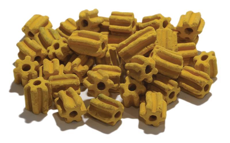
Experience the next level in pressure drop reduction with BASFs new X3D™ Sulfuric Acid catalyst series based on 3D printing. A pressure drop reduction of up to 75% in comparison to Star Ring catalysts can help you to reduce the energy consumption of your converter.
Simulated pressure drop

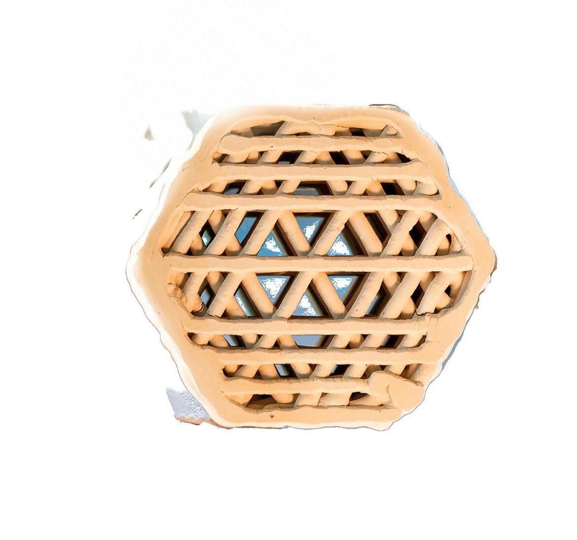
Higher conversion Lower energy consumption Decreased SO2 emissions
Stainless steel converters, gas heat exchangers, and ducting were introduced into the sulfuric acid industry in the early- to mid1980s. Although their use was expected to end the scaling problems associated with carbon steel converters, it was quickly noted that scale did appear. In some instances, scale appeared in large enough quantities to cause early equipment failure and pressure drop increases in catalyst beds.
At the time, studies were conducted and the results were disseminated through papers and presentations. These works described the scaling mechanism, identified the influencing variables, and confirmed industry observations. Specifically, scaling was found to create primarily aesthetic issues and occasional pressure drop concerns, but it did not cause significant equipment damage. Notably, when left untreated, the extent of scaling diminished and eventually ceased over time.
Knowledge that was widely recognized within the industry more than two decades ago has, to some extent, been lost due to workforce turnover. The purpose of this article is to revisit those earlier findings and provide an updated perspective based on subsequent experience.
The earlier findings described in this article are from the work conducted by Ives, Coley, and Rodda at the Walter W. Smeltzer Corrosion Laboratory at McMaster University in Hamilton, Ontario and reported in their study Corrosion in Hot Gas Converters of Sulphuric Acid Plant. This study, hereafter referred to as the McMaster paper, is presumed to have been produced around 2003, although no official publication date is available. Subsequent publications and presentations have referenced this work, including the Handbook of Sulphuric Acid Manufacturing (Cole, 2006). Related information is also available through Sulphuric Acid on the Web, a site presented by DKL Engineering (DKL Engineering, n.d.). This article revisits these findings and provides updates to the current period.
In the mid-18th century, the lead chamber process was introduced to produce concentrated sulfuric acid on an industrial scale. The process involved a series of corrosion-resistant lead-lined vessels or chambers–hence the name. The technology used nitric oxides to convert the SO2 obtained from burning sulfur or metallic sulfide ores such as iron pyrites. SO2 to SO3 oxidation and absorption in water occurred as the gas cooled and the sulfuric acid condensed. At this time, “concentrated” refers to sulfuric acid at a strength of 60%, while “industrial scale” denotes production capacities on the order of several dozen tons of acid per day. Not impressive by today’s
By: Walter Weiss, Elessent Clean Technologies
standards, but a significant improvement over production in lab glassware at the rate of a few kilograms per day. Evaporators could be used to drive off some of the water and increase sulfuric acid concentration.
Early process improvements were the addition of the Guy-Lussac tower which increased reaction rate and nitrogen oxide recovery by introducing stoneware tiles in which gas and liquid contacting occurred. This increased surface area for contact—an early example of a packed tower. Further improvements included the introduction of the Glover Tower, which operated under heated conditions, allowing increases in concentration (upwards of 80%) and some increase in capacity. Given the vessel’s lead lining and low operating temperatures, scaling was not known to be a problem.
In the 1920s, the contact process was introduced to largely supplant the lead chamber process. This succession took place over the next twenty years. The contact process utilized a catalytic means to convert SO2 to SO3 in a vessel known as a converter. SO3 was then absorbed in packed towers with circulating strong sulfuric acid. Acid could be produced at 98% concentration and production rate of several hundred tons per day was possible. The oxidation reaction rate was equilibrium limited such that multiple converter passes (three or four) were used with intercooling between the catalyst passes. This led to a number of gas heat exchangers being used to exchange heat and interconnecting ducting around the converter to tie all this together. Overall conversion rates up to 98% of the inlet SO2 to pass one kept emissions around 2000 ppmv.
To achieve conversion, SO2 gas concentration was often limited to 9-10%. Equipment was made of carbon steel, and converter internals used a cast iron set of grids and posts. Temperatures could reach as high as 618°C (1145°F) in the first converter pass and all other passes operated between 425°C (800°F) and 500°C (930°F). The carbon steel was known to scale under these conditions. Short-term protection could be obtained by metallizing—the spray application of an aluminum coating. “Alonized tubes” were dipped or rolled in aluminum and baked to obtain the same protection. The metal protection wore off after several years. The design intent was to reapply from time to time. That did not always happen. Failure to do this effectively led to the scaling of the bare carbon steel.
In the mid-1970s, increasingly stringent environmental regulations led the sulfuric acid industry to adopt double absorption designs. The core process concept remained unchanged, but additional equipment—including an intermediate absorption tower and two supplementary gas heat exchangers—was introduced. The materials of construction for the converter, gas heat exchangers, and interconnecting ducting remained consistent with those previously in use.
SO2 gas concentration could be increased to 11.5 or 12% and still obtain conversion rates
of 99.7% and emissions around 400 ppmv. Higher gas concentration meant higher converter bed temperatures. These could reach as high as 630°C (1165°F) in the first converter pass and all other passes operated between 425°C (800°F) and 520°C (970°F). Scaling issues got worse as did sagging and deformation of the cast iron internals. The industry was looking for alternate materials.
After sixty years of experience with carbon steel and cast iron in high temperature service, the problems were universal and well known. Stainless steel was introduced as an alternate material in the early 1980s and became more commonly used as new plant and equipment replacement projects continued through the rest of the decade. The industry was ready for a future that utilized non-scaling materials in the converter area. So, it was an unexpected and unexplained surprise when scaling was noted during the first turnarounds. This was observed in converter areas on both sides of the US-Canadian border.
The material selected for this service was 304 stainless steel, chosen for its wide availability and relatively low cost. This austenitic stainless steel, commonly referred to as 18/8 due to its composition of approximately 18% chromium and 8% nickel, is often supplied in low-carbon grade 304L (≤0.03 wt% carbon), specified simply as 304. However, 304L lacks the required strength at elevated operating temperatures. To address this, converters and ancillary equipment were specified to use 304H, which contains up to 0.08 wt% carbon, or alternatively 304 stainless steel with a minimum carbon content of 0.04%, thereby avoiding inadvertent substitution with 304L.
To the extent studied, the material used for fabrication matched that as specified, yet scaling was observed. The higher the temperature, the greater the amount of scaling. The scale was loosely adhered to the metal wall. It often flaked off due to thermal expansion and contraction of the metal with thermal cycles. Fallen material often lay on the catalyst bed surface, and some was thought to have blown from upstream surfaces. In severe cases, this resulted in high pressure drop buildup of the catalyst bed and early screening requirement. Passes two and three collected the most scale
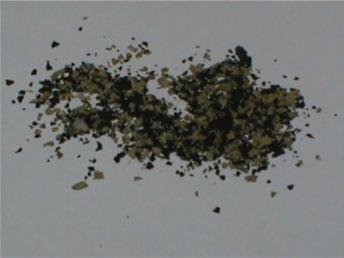
and had the highest rates of pressure drop. This is consistent with the highest gas temperatures of the system at the outlet of the preceding passes.
Much of the material not flaking off during cooldown could be removed by simply rubbing the metal surface with a soft cloth or a nylon brush. The scale was dark grey or black on the side away from the metal surface and reddish brown on the side against the metal. Despite the relatively large amount of scale, metal loss measurement indicated very little shell wall thinning.
By circumstance, much of the early stainless steel converter-area equipment was installed in metallurgical acid plants serving the nickel and copper industries, with at least one application in high-NOx spent acid regeneration. Attack of the 304 stainless steel by NOx compounds was an early explanation, and so was the possibility of small amounts of metallic ions, such as cuprous ions, making it to the converter through gas cleaning. As increasing instances of stainless steel scaling were observed in sulfur-burning plants— facilities characterized by low NOx levels, no gas cleaning with minimal concentrations of metallic ions—the initial explanations were reconsidered and ultimately deprioritized. It became evident that additional mechanisms were involved.
Since the increase in pressure drop was manageable and the equipment life was not significantly shortened due to thinning from this scaling phenomenon, the next ten years were spent dealing with this as a normal condition for stainless steel materials, and the use of 304 stainless steel continued. By the mid-1990s, there were some 40 stainless steel converters sold worldwide—at least in the Western world. More 304H converters were suspected to have been sold by other equipment suppliers globally.
In the mid to late 1990s, McMasters University, in conjunction with five unidentified Canadian sulfuric acid metallurgicalbased plants, began a coupon analysis program. Coupons were evaluated during cold shutdowns of the smelter and then returned. These occurred every one to two years, depending on smelter shutdown schedules, with the timing determined by operational constraints rather than the study design. The study period extended from 1995 through 2003.
Coupons of fifteen materials were studied, which included two coupons of 304H as well as 321H, 309 and 310 austenitic stainless steels. Other coupons were duplex stainless steels. Early focus was on the chromium content of the materials.
• 2509 had the lowest chromium concentration at 9%
• A611 and 321H had chromium concentrations of 17%
• 304H, 1815LCSI, and RA85H had
chromium concentrations of 18%
• 253MA had a chromium concentration of 21%
• 309 had a chromium concentration of 22%
• 310 and KHTR 35H had chromium concentrations of 25%
• R20033 (Alloy 33) had the highest chromium concentration at 33%
Coupons were placed at the outlet of pass one (normally operated at 590-635°C) and inlet of pass two (normally operated at 420-440° C). Gas composition should be the same at both locations given that there is no significant leakage in the hot heat exchanger. Levels of NOx and any metallic impurities should likewise be the same. Temperature data was logged, as was the gas composition (SO2 and O2). These variables were a function of the smelter operation and beyond the control of the experiment. Coupons were removed during shutdowns, cleaned of the loose scale and weighed to determine corrosion rate from weight loss per coupon surface area.
In early findings, it was observed that increased chromium and nickel content was not necessarily effective at reducing the one-year corrosion rate for low silica alloys. Most of the austenitic alloys noted above contained around 0.5 wt% silica or less. Higher silica alloys such as 253MA, A610 and A611, RA85H, and 2509 showed a reduction in corrosion rates by two-thirds or more. These materials contain from 2-7% silica. It was also noted that the higher the silica content, the lower the observed corrosion rate. This is good academic information, but use of high silica steels in this service is a concern for equipment design given concerns about high silica content potentially leading to metal embrittlement at these temperatures. The McMaster paper encouraged evaluation of material strength at these temperatures.
Limiting the review to lower silica content alloys, the McMaster paper noted that 304H may not be the best alloy for the service. At 425°C, one-year corrosion rates of 304H were 0.5-1 mpy. At 625°C, the corrosion rates climbed to 1.5-6 mpy. Comparing these rates to those of other austenitic alloys such as 309, 310, or R20033, one-year corrosion rates were 0.25 mpy at 425°C and 1-2 mpy at 625°C. Corrosion rates did increase rapidly after that. For 309 and 310 stainless steel, corrosion rates were similar to those of 304H once the temperature exceeded 635°C. Using some of these other austenitic steels at all but the highest converter temperatures was believed justified.
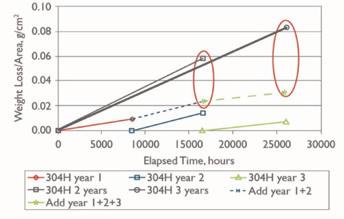
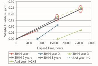
It was also noted that corrosion was not linear with time (Fig. 1).
A gradual decrease in corrosion rate is observed from year to year. This is non-linear, quite possibly due to the lack of control over time and process variables in the experiment. Industry experience also suggests that the observed amount of scaling at 425°C does decrease with time.
At 625°C, the corrosion rate continues unabated for a longer period of time. Again, not linear but (1) the magnitude of corrosion was higher than at 425°C by six to eight-fold, and (2) the rate of decay in corrosion rate over time was less, meaning that the scaling continued further into the operating period of the equipment.
Micrographic evaluation of 304H coupons suggested that there was minor modification to the microstructure after three years of service, even at 625°C or higher temperatures. This was not thought to be significant enough to change the strength of the material. Plant measurements showing little or no thickness loss, along with no loss of material strength, suggested that the materials remained suitable for service.
Other coupons analyzed by micrograph from the silica-rich set of materials showed a more significant microstructural change with the formation of a silicon-rich phase as a subscale layer. This likely explained the corrosion resistance of these materials.
Scale thickness levels of 0.1-0.2 mm are reported. Per Fig. 3, the depth of the boundary layer is 2/3 the total thickness, suggesting a chromium oxide layer of 0.05-0.1 mm thick with the rest being a loosely adhered sulfide layer. Both sulfides are black in color, but depending on actual composition, nickel sulfide can take on a bronze hue, and the iron sulfide as iron disulfide, is known as fool’s gold from its yellow hue.
The McMaster paper theorized that at 425°C, the residual scale is more adherent than at 625°C. The three-year summation of corrosion rates shows a significant decline with time atop bed two. Whereas at the conditions below bed one, the correlation between early projected corrosion rates and individual two- and three-year corrosion rates is much more consistent. This raises the topic of scale chemistry and structure.
The volume of scale was significant relative to the amount of wall metal loss. This gave a perception of more corrosion damage than was actually occurring. Metal wall thickness testing did not reveal concerning amounts of metal loss.
The wall thickness of the vessels is generally ¼ inch (6 mm). Corrosion rate at 425°C in the first year was roughly 1 mpy with declining rate over time. The firstyear metal loss was 0.001 inch or 0.4% of the shell wall and declining after that. Corrosion rate at 625°C in the first year was 2 mpy roughly. This first-year metal loss would have been 0.002 inch or 0.8% of the shell wall. This would be expected to continue for multiple years. Of more concern was similar corrosion rates on the hot end of the heat exchanger tubes, which would be attacked from both sides. Tube wall thickness for 14-gauge tubes is 0.083 inches (2.1 mm). Even so, plants were not observing early failure of the hot gas heat exchanger tubes in this time period. Noting here that the tube metal, even though exposed to pass one outlet gas at 625°C inside the tube, is cooled by pass one inlet gas at roughly 425°C, leaving a tube wall temperature near 525 °C.
Formation of the scale was explained in the paper as a truly phenomenal process of the natural world. It is believed that higher levels of chromium with oxide film at the metal surface are needed to protect the base metal for 304H and the other austenitic alloys. The McMaster paper did not reveal the chromium content of the protective chromium oxide layer. It is expected to be enriched from virgin material and is expected to be driven to higher levels as a function of the rate and amount of scaling. Once 304H stainless steel is formed with 18% chromium, it is not so easy to add additional chromium. But nature has found a way to increase the chromium content to higher levels at the interface by locally sluffing off the unwanted nickel and iron. The scale is found to have iron rich and nickel rich layers comprised of metal oxides and metal sulfates but not much in the way of metal sulfides.
As part of this sluffing, oxygen needs to diffuse through the scale and oxidize the chromium at the interface. Laboratory results on oxidation rates of the 304H samples showed little difference in rate at 420°C but nearly an order of magnitude increase in oxidation rates at 625°C versus 425°C.
This prescribed methodology is shown in the depiction from the Handbook of Sulphuric Acid Manufacturing noted in Fig. 3. Sulfur-bearing gases and oxygen diffuse into the base metal, and the iron and nickel, as oxides and sulfides diffuse outwards into the scale. This reference uses the term “sulfides,” which is somewhat at odds with the McMaster paper claiming the majority of the chemical form is as sulfates. This is based on the presence of H2S gas upon acid wash of the samples.
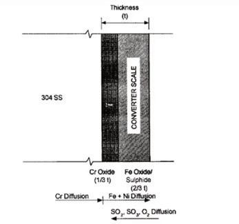
The Handbook of Sulphuric Acid Manufacturing goes on to advise that the lightly adhered scale of iron and nickel is readily removable, but the more robust layer of chromium oxide should be retained. Aggressive cleaning using wire brushes or wire wheels removes this protective scale and returns the shell wall to the original 18/8 steel. Hence the scaling process goes back to the starting point and begins anew.
More than forty years have passed since the introduction of stainless steel equipment into the converter area. MECS, Inc. has designed more than 200 stainless steel converters around the world and all of them in 304 stainless steel with a carbon content greater than 0.04%. Many of the early- to mid-1980s stainless steel converters are still in operation. Those that are no longer in operation reflect plant closures more than converter equipment failure. Contributions from other technology and equipment suppliers likely bring the global total to around, or possibly above, 500 units, with the number in China remaining uncertain. The vast majority, maybe all but one, are believed to be constructed of 304H stainless steel. The industry has adapted to screening work and scale removal associated with scaling, especially upstream of passes two and three during the first years of converter operation. Added costs and complexity for using alternate materials are not valued options—at least not yet.
The McMaster paper still sews the seeds of alternate materials for use in the outlets of passes one and two, including ducts and possibly gas heat exchanger tubes. At the time of the McMaster paper as well as today, 310 and 321 stainless are used in these hot sections of equipment and ducting, mostly for catalyst support screens as well as bellows expansion joints, which are thin metal sections less tolerant of scaling. The view of the McMaster paper is that the use of 304H stainless steel is unsuitable. From the data, 310 and 321 stainless steels are marginally better. Alloy 33 shows some promise, but at 33% chromium and 31% nickel, this will be a costly upgrade. q
References
1. Cole, D. R. (2006). Handbook of Sulphuric Acid Manufacturing. D. R. Cole.
2. DKL Engineering. (n.d.). Sulphuric Acid on the Web. DKL Engineering. http:// www.sulphuric-acid.com
3. Ives, M. B., Coley, K. S., & Rodda, J. (2003). Corrosion in Hot Gas Converters of Sulphuric Acid Plant. Walter W. Smeltzer Corrosion Laboratory, McMaster University. (Unpublished manuscript)
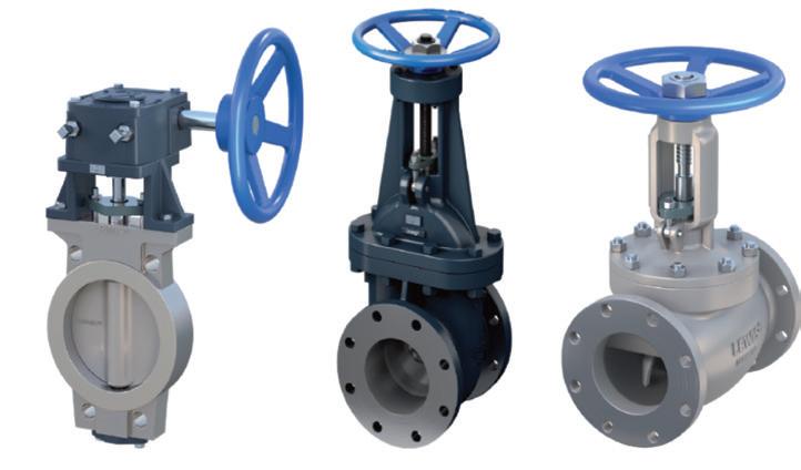
Weir has long been a trusted name in the manufacture of gate, globe, and butterfly valves designed specifically for high temperature and high concentration sulfuric acid production. Lewis® gate, globe and butterfly valves are built for sulfuric acid concentrations ranging from 93% to 99.5%, including oleum, and are rated for operating temperatures up to 460°F (240°C) and pressures up to 150 psig (10 barg).
Lewis® gate valves are ideal for on-off application, where tight shut-off is mandatory and cannot be compromised. They feature:
• Outside screw and yoke
• Bolted bonnet
• Flexible disc
• Rising stem with non-rising handwheel (for sizes above 1 inch / 25 mm)
End flanges are flat-faced or raisedface and customizable to ANSI, BS, DIN, or JIS standards. Face-to-face dimensions conform to ANSI B16.10, with DIN 3202 Series F4 options available.
Available in sizes from ½ inch (15 mm) to 30 inch (750 mm), for sizes ½ inch (15 mm) to 4 inch (100 mm), valves are constructed entirely from Lewmet® alloys. Sizes 6 inch (150mm) to 30 inch (750mm) incorporate a composite design: alloyed iron body and bonnet, alloy 20 stem, Lewmet® stem connector, and dual flexible discs with seating rings. This mirrors the construction of Lewis® vertical acid pumps, offering an optimal balance of cost and performance.
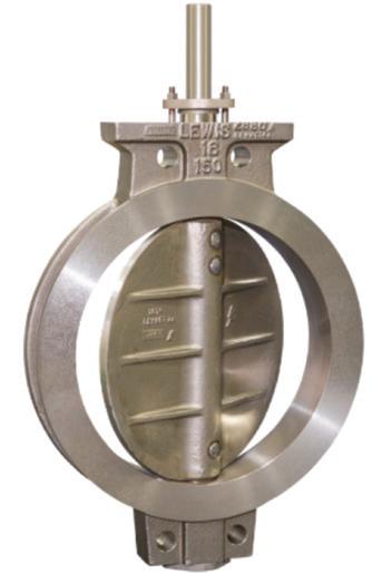
In high-temperature heat recovery applications (up to 460°F / 240°C and acid concentrations up to 99.5%), valve components are upgraded to Lewmet® 15 duplex stainless steel and Lewmet® 66 stainless steel for the stem. For valves 12 inch (350 mm) or above, mechanical gear operators or electric/pneumatic actuators are available.
Lewis® butterfly valves are widely used in conventional sulfuric acid plants, particularly for controlling bypass flow in cooler loops and balancing tower flows. To meet the demanding needs all butterfly valves are constructed of Lewmet® alloys for the 8 sizes available from 4 inch (100 mm) to 24 inch (600 mm), the 4-inch model can be configured with 2-inch or 3-inch equivalent flow discs. The wafer style “swing-through” design meets ANSI Class 150 face-to-face dimensions and is compatible with ANSI, DIN, BS, and JIS flanges.
Butterfly valves are not designed for tight shut-off but excel in flow regulation. Engineers should calculate the valve coefficient (Cv) using the formula:

Ideal disc openings range from 30-65 degrees, corresponding to 7.5% to 50% of full Cv. This ensures effective throttling without premature wear. Lewis® butterfly valves have demonstrated long-term durability, even in near-closed positions, thanks to the superior corrosion resistance of Lewmet® alloys.
Valves may be one or two sizes small-
er than the pipeline, requiring reducers. However, excessive reduction can cause turbulence and damage to reducers (though the valve itself remains unaffected).
As quarter-turn valves, Lewis® butterfly valves are easily automated. Proper actuator selection depends on maximum shut-off delta P, which determines breakaway torque. Lewis® valves provide full engineering, machining, and calibration services to ensure reliable integration.
Lewis® globe valves are ideal for both on-off and flow control applications. Available in sizes from ½ inch (12 mm) to 6 inches (150 mm), which are designed for 93–99.5% sulfuric acid, oleum up to 460°F (240°C), and 150 psig (10 barg).
Valves from 2 to 6 inches feature Lewmet® nickel-chrome bodies and trim, with bolted bonnets and rising stems. Smaller sizes (½ to 1 inch) include rising handwheels and modified parabolic plugs. Flanges are typically flat-faced and drilled to BS or JIS standards.
Globe valves exhibit linear flow characteristics. This depends on the valve’s internal plug or disc design. A linear globe valve provides a flow rate that is directly proportional to the amount of valve travel, meaning if the valve opens 50%, it will pass approximately 50% of its full capacity. Optimal control is achieved when stem travel ranges between 25% and 75% of full stroke. This ensures the valve operates in its most responsive and controllable zone, leading to better process performance, longer valve life, and more efficient system operations. Like butterfly valves, globe valves can be automated, with actuator selection based on maximum delta P and fail-safe positioning requirements.
For acid concentrations up to 99.5% and temperatures up to 460°F (240°C), Lewmet® 15-A duplex stainless-steel construction is available. These valves offer high resistance to corrosive and erosive wear. Even under elevated fluid velocities, where the kinetic energy of the flowing medium intensifies mechanical erosion, accelerates corrosion rates, and increases the risk of cavitation and turbulenceinduced damage, Lewmet® valves demonstrate exceptional resilience. Unlike conventional Alloy 20 valves that degrade rapidly in such aggressive conditions, Lewmet® valves maintain their structural integrity and sealing performance. This capability to withstand high-velocity flow environments not only ensure uninterrupted operation but also contribute to a lower total cost of ownership by reducing the frequency of valve replacements, minimizing maintenance labor, and preventing costly unplanned shutdown
Lewmet® valve and material range offers exceptional corrosion resistance across a wide range of acid concentrations (93% -99.5% sulfuric acid and oleum), is non-galling, and can be hardened beyond 450 Brinell without compromising corrosion resistance. One Canadian producer overcame persistent valve failures associated with Alloy 20 by transitioning to Lewmet® valves. This switch not only delivered complete reliability and minimized downtime due to fewer valve replacements, but also significantly reduced the total cost of ownership. The superior durability and corrosion resistance of Lewmet® valves eliminated frequent maintenance cycles and unplanned shutdowns, resulting in long-term operational savings and improved process efficiency.
Since their introduction in the mid1970s, Lewis® valves have consistently delivered exceptional field performance, even in extreme conditions. Many installations have operated reliably for over a decade with minimal maintenance, requiring only packing replacements, while spare valves have remained unused in inventory. Weir continues to set the standard for valve technology in sulfuric acid applications, combining advanced metallurgy, precision engineering, and field-tested reliability. For more information, visit www. global.weir. q


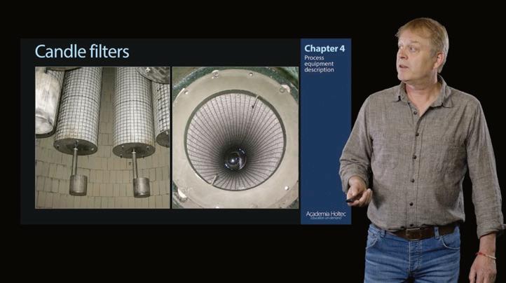
After the launch in 2024 of our asynchronous online courses for metallurgical sulfuric acid plants, Academia.Holtec is pleased to present our asynchronous online course for sulfur burning acid plant operations.
With 25 years of experience in sulfuric acid plant technologies and operations, Academia.Holtec has been providing technical and professional training to sulfuric acid plants for over two decades.
The recently launched basic training course for sulfur burning plants consists
of relatively short texts, videos, quizzes, and tests, accompanied by examples of real cases taken from the industry. The material is presented in a step-by-step fashion, allowing operators to complete the training modules at times that fit their individual schedules, without needing to coordinate availability with others.
Effective operator education is crucial for all aspects of sulfuric acid plant operations. Continuous learning strengthens job security, career growth, and overall plant performance.
As Matias Keskimäki, Production Engineer at Boliden Harjavalta states:
“Acid plant training deepens knowledge of all aspects of sulfuric acid plant operations, including the chemical reactions and substances that are present in a plant. It is important to increase awareness of the different processes in a plant. That can help significantly with problem solving.”
For operators and engineers, the training material provides a structured introduction to basic chemistry and physics concepts of sulfuric acid plants. The theoretical basics
are related to equipment design, process control, plant safety, and environmental performance. The objectives: bridge knowledge gaps, standardize skills, reinforce safety procedures, and reduce operational errors.
As the sulfuric acid industry evolves, investing in employee development and pri-
oritizing human talent as a strategic asset is crucial for ensuring long-term sustainability and operational excellence.
For more information, please contact Dirk van der Werff (dirk.vdwerff@holtec. cl) or visit the company website at www. academia.holtec.cl. q


Most sulfuric acid plants run reliably at steady state. Temperatures are stable, flows are predictable, and equipment tends to behave the way it was designed. Yet if you look back at your plant’s history of failures (cracked expansion joints, warped ductwork, seized dampers, blower trips) you’ll notice that most didn’t happen on a calm Tuesday afternoon at steady load. They happened at startup and shutdown, when systems are in flux and stresses are at their highest.
It’s easy to overlook these transients, but ignoring them is costly. A single poor startup can take years off the life of critical equipment. A rushed shutdown can create the conditions for your next unplanned outage. Let’s break down why, and what you can do about it.
When you bring an acid plant online or offline, you’re putting the system through rapid changes in temperature, pressure, and flow. These transitions introduce stresses that your equipment never sees under steady operation.
• Thermal expansion and contraction: Steel ductwork and expansion joints move as they heat or cool. The math is simple: carbon steel grows/shrinks about 0.078 inches per 10 ft for every 100°F. So, if you shut down from 700°F to ambient, a 100 ft run of ducting can shrink nearly 5 inches. If your expansion joints aren’t designed for that contraction, something else will take the load, like a nozzle, anchor, or damper frame.
• Differential heating: A hot gas stream hitting cold metal creates local stress points. Converters and ductwork are particularly vulnerable when burners are lit too quickly. Refractory dry-out schedules limit ramps to ~50–100°F/h with holds; exceeding manufacturer schedules increases spall/crack risk and can overstress thinwall ducting.
• Condensation and dew point: As gas cools, SO2 and H2O combine to form H2SO4 in places you don’t want it. Such as low elbows, expansion joint convolutions, damper blade and shaft seals, or stuffing boxes. Avoid metal or gas temperatures below the H2SO4 dew point, typically 250–300°F.
• Stress cycling: Every startup/shutdown is a fatigue event. Even if nothing breaks today, repeated cycling reduces the lifespan of bellows, dampers, and supports.
By: CJ Horecky, Executive Director, INTEREP
Not all equipment suffers equally. A few components consistently take the brunt of transient stresses:
• Expansion joints: Rapid thermal growth pushes them past design movements. On shutdown, pooling condensate corrodes bellows from the inside out.
• Dampers & valves: Think of dampers as big valves for gas handling. During cool-down, shafts seize, blades warp, and seals leak if tolerances weren’t set with thermal movement in mind. Many “mystery leaks” blamed on ductwork are actually damper components failing after a rough cycle. Damper stuffing boxes and shaft seals are seldom, if ever, maintained. Yet they are one of the most common leakage points during startup and shutdown cycles. A simple inspection or repack during a shutdown can prevent chronic SO2 leaks and extend damper life.
• Pipe supports & guides: Misaligned sliding supports can turn into anchors when ductwork grows, adding unplanned movements.
• Blowers & fans: Misaligned bearings and thermal growth cause vibration, while sudden load changes at startup test the limits of motors and shafts.
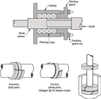
• Lighting burners too aggressively to get online faster.
• Failing to control startup temperatures or ensure gradual heating of equipment downstream of burners. Make sure to consider the coldest points of all equipment on your startup heating curve and consider the maximum temperature reached at those points during startup. That may mean
going higher than operating temperature to evaporate potential condensation in equipment low/cool spots.
• Forgetting to flush & drain low points before a shutdown, leaving dilute acid to concentrate.
• Forgoing expansion joint inspections during shutdown, which is an optimal time to mark and record cold positions.
• Skipping inspection of spring supports, slide plates, tie rods, and damper seals before restart.
• Allowing ambient air infiltration during cooldown, which accelerates corrosion and steals blower capacity.
Notice I said equipment stress; that rules out general startup and shutdown stress, which some of you deal with by consuming copious amounts of caffeine and nicotine. Most transient-related equipment failures are preventable. Here are proven ways to reduce risk:
• Control ramp rates: Keep heat-up/ cool-down under 50–100°F/hr (with holds) where possible. Your refractory and your ductwork will thank you.
• Check expansion allowance: Use the simple growth formula (ΔL = L × α × ΔT). For carbon steel (α ≈ 6.5×10 -6 in/in/°F), a 50-ft duct run dropping from 700°F to 100°F will shrink about 2 inches. For 300-series stainless steels (α ≈ 9.6×10 -6 in/ in/°F), that same 50-ft run dropping from 700°F to 100°F will contract by about 3 inches. Is your EJ designed for this?
• Drain & purge: Open drains at shutdown, especially near elbows and low joints. Nitrogen sweeps are preferred to prevent air ingress and sulfur fires.
• Instrument & monitor: Temperature probes, UT readings, thermal scans, and expansion joint test ports provide early warning of stress.
• Service dampers like valves: Treat damper inspections the way you would valve PMs. Verify seal integrity, shaft
freedom, and thermal clearances before startup.
• Train operators on sequence discipline: Most shutdown damage is human error. A written, enforced sequence can save equipment and downtime.
Rule of thumb: Every 100°F of change moves your duct about 1/12 inch per 10 ft (carbon steel), or closer to 1/10 inch per 10 ft (stainless). Make sure your expansion joints and dampers are sized for both the growth on startup and the contraction on shutdown.

One cracked expansion joint can take your plant offline for days. A seized damper blade or stuck shaft can back up an entire system. A seized blower bearing can cost more in lost production than a year’s worth of preventive inspections. The cost of controlled ramping, drain checks, and operator training is tiny compared to the millions of dollars tied to uptime. Put simply: investing in transient discipline is the cheapest reliability insurance you can buy.
Your sulfuric acid plant doesn’t usually fail when it’s running steady; it fails when it’s starting or stopping. If you focus your inspection, monitoring, and training efforts on these windows of vulnerability, you’ll extend the life of your equipment, avoid emergencies, and maximize uptime. Steady-state doesn’t kill your plant, transients do. Respect the startup and shutdown, and the uptime will follow.
For more information on INTEREP’s services, visit www.interep.us. q
By: Ethan Schrader, Product Manager, AirBTU, CG Thermal
Every sulfuric acid producer knows the pain of unplanned downtime. When a cooler goes down, production slows or stops and economic losses accumulate quickly. Among the most notorious trouble spots in this process are adiabatic gas coolers—the workhorses that rapidly cool sulfur dioxide (SOx)–laden gas streams before they move downstream.
But these coolers face a unique enemy. As the gas temperature drops through the 300–450°F window, sulfuric acid begins to condense. This creates a “perfect storm” of corrosive conditions, attacking metal surfaces at their most vulnerable. Over time, the result is predictable: localized damage, expensive repairs, and shutdown cycles that no plant manager looks forward to.
For years, operators have treated this phenomenon as an unavoidable cost of doing business. CG Thermal, however, is working to change that narrative. Their latest efforts with ceramic nozzles may point to a long-term solution—one that could extend service life well beyond the traditional two-year cycle and reshape expectations for corrosion resistance in sulfuric acid production.
Adiabatic gas coolers perform a deceptively simple task: they spray water into hot SOx-laden gases, reducing the temperature to a level that is safe for downstream equipment. In practice, however, the process is anything but simple.
As the gas cools, it passes through the most corrosive temperature range found in sulfuric acid processing. Metals exposed to this “danger zone” suffer rapid degradation. Engineers have long worked around the issue by using corrosion-resistant alloys and by designing cooler lids that can be swapped during planned shutdowns.
Typically, plants schedule two-week outages every two years, replacing the cooler lid (which houses the nozzle, gas connection, and spray system) while leaving the rest of the vessel in place. This strategy works, but it also bakes recurring downtime and repair costs into the production schedule. The dream of extending service life to four years or longer has been tantalizing but elusive.
CG Thermal’s engineering team saw an opportunity to bring their expertise in ceramics into play.
Ceramic materials, already proven in other corrosive environments, offer neartotal resistance to the conditions that destroy metal nozzles.
The challenge wasn’t in the chemistry—ceramics don’t corrode in SOx-rich environments—but in the mechanics. How do you attach a brittle ceramic structure to a metal cooler lid that expands and contracts at different rates under extreme heat?
To solve this, CG Thermal turned to computational fluid dynamics (CFD) modeling. The simulations helped pinpoint the exact location of the corrosion zone, allowing engineers to design a protective system targeted to that high-risk band. The answer was an interlocking ceramic cladding system: a ring of plates installed inside the nozzle, held in place by a mechanical clamp assembly.
The concept was elegant: let the ceramic take the punishment while shielding the metal beneath. The result was a nozzle with double the life—eliminating an entire shutdown cycle.
The first test came in October 2024, during a scheduled three-week outage. The plant installed a new cooler lid featuring the ceramic nozzle. The integration process was straightforward: remove the old lid, drop in the new one, weld the connections, and restart operations.
At startup, the cooler performed as expected. SOx gases cooled properly, water spray operated smoothly, and the plant returned to full production.
Months later, an issue surfaced in which fragments of metal appeared in the water circulation pump. Investigations traced them back to the clamp system holding the ceramic plates. Corrosion had eaten away at the clamp hardware, leading to partial failure.
And yet, aside from the clamp problem, the ceramic plates themselves told a different story. Post-removal inspection revealed that the ceramics were untouched by corrosion. The metal nozzle behind them was also largely intact—a sharp contrast to the heavy degradation seen in traditional designs. In short: the concept worked, but the hardware around it needed refinement.
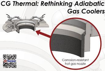
Quench Lid Advanced: Patent-pending corrosion-resistant nozzle and lid design for adiabatic gas coolers, extending service life and reliability in harsh sulfuric acid environments.
The first field trial provided valuable proof of principle. Most importantly, it confirmed that ceramic materials can survive the harshest conditions inside an adiabatic gas cooler. Where metal fails, ceramic endures.
But the test also exposed the pitfalls of combining ceramic cladding with metal clamps. Real-world gas flow can shift, creating unexpected corrosion hotspots. The clamp hardware, though not predicted to be in danger, ended up corroding aggressively.
Several lessons emerged from the experience:
• Simplify the flow path. Internal clamp structures create dead zones where gas can stagnate, increasing corrosion risk. A smoother, straight-through nozzle design could solve this.
• Upgrade attachment materials. Even if simulations suggest low risk, any exposed metal in this environment is a liability. Stronger, more corrosion-resistant alloys should be used for mechanical supports.
• Think bigger: full ceramic. Instead of cladding metal with ceramic, why not design the nozzle entirely from ceramic? This would eliminate the risk of corrosion behind the protective layer altogether.
These insights are now shaping the next generation of CG Thermal’s cooler nozzle design.
A revised ceramic nozzle has been installed and is operational at another sulfuric acid facility. This time, the design will incorporate the hard-won lessons from the first trial:
• No internal clamp geometries to disrupt gas flow.
• Higher-grade materials for any attachment hardware.
• Exploration of ceramic as the primary
nozzle material rather than just protective cladding.
The second installation will serve as a critical proving ground. With similar process conditions but a fresh environment, the test will allow engineers to track performance and verify that the improved design solves the clamp issue without sacrificing flow efficiency.
This study established ceramic nozzles as the new standard in sulfuric acid adiabatic cooler design.
The sulfuric acid industry has long lived with the reality of nozzle corrosion. Plants budget for downtime, stock replacement lids, and accept a two-year service life as the norm. But the economics of production are shifting. Every avoided shutdown translates to substantial cost savings and improved output.
By extending nozzle life to four years or more, operators could skip entire outage cycles, reducing not just repair costs but also lost production revenue. Over the lifetime of a plant, these savings add up to millions.
Beyond economics, addressing this corrosion in turn addresses sustainability. Longer-lasting equipment means fewer replacement parts manufactured, shipped, and scrapped. A move toward ceramic technology could quietly reduce the industry’s environmental footprint while improving reliability.
The first ceramic nozzle test wasn’t perfect, revealing that the clamp system required further improvement. But the trial accomplished something more important: it proved that ceramics can handle the most corrosive zone in sulfuric acid coolers without flinching.
The refined design was installed in late 2025, marking a major step toward resolving one of the industry’s longest-standing reliability challenges.
For decades, corrosion in the cooler nozzle has been considered inevitable. Thanks to advanced materials and smarter design, that assumption may soon be outdated. The story of ceramic nozzles is still being written, but the first chapters suggest it could be a game-changer.
For more information, please visit www.cgthermal.com. q
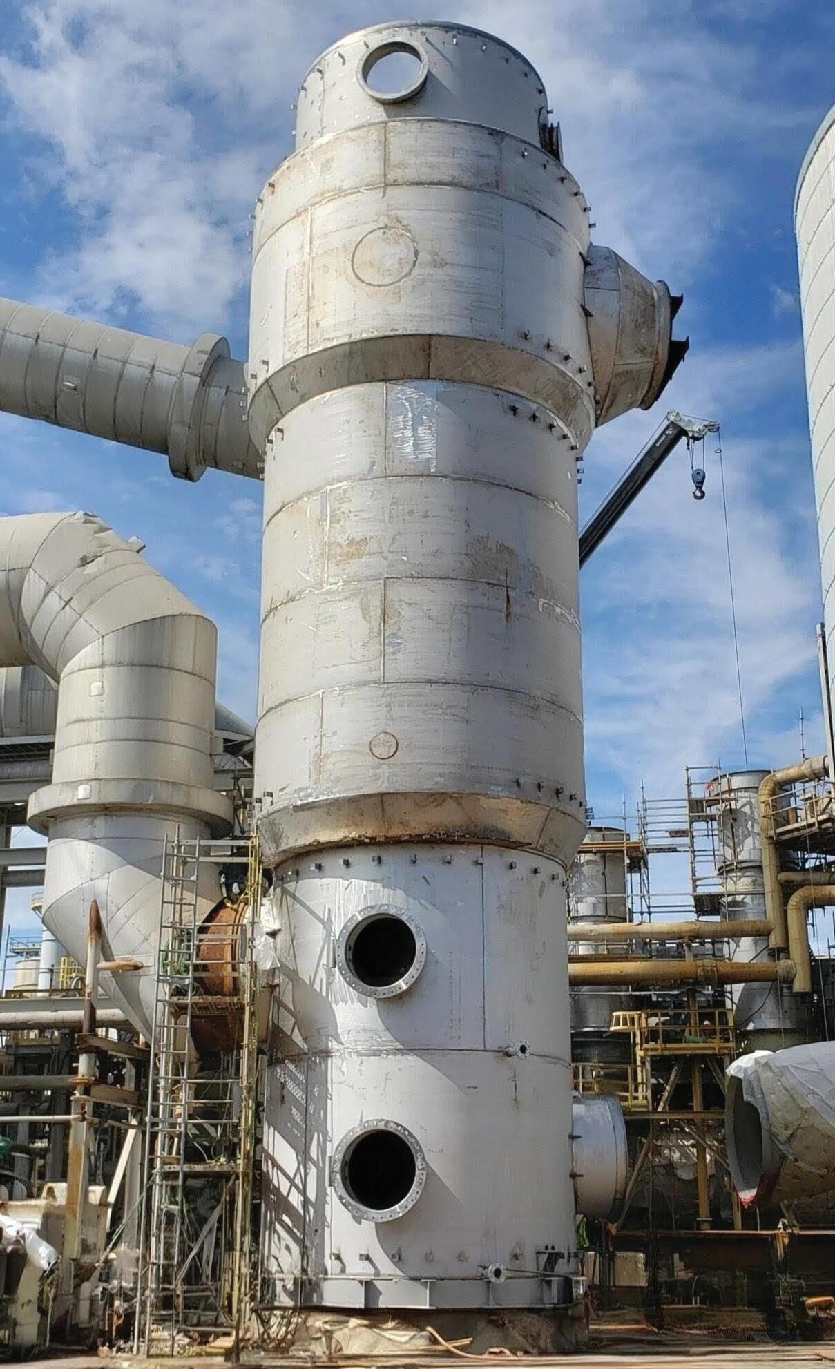
By: Mathijs Sijpkens and Jan Hermans, Sulphurnet
Lime dosing is often regarded as a basic and routine procedure in sulfur melting plants. However, its importance is frequently underestimated leading to significant downstream issues and costly operational setbacks. What begins as a straightforward chemical adjustment based on the sulfur quality datasheet can quickly escalate into equipment damage, extensive audits, laboratory investigations, unplanned downtime, and loss of revenue.
At Sulphurnet, we have supported numerous clients who initially attributed performance problems to equipment faults, only to discover that the root cause lay in improper neutralization practices. In this article, we explore the underlying causes, and effective solutions to ensure reliable and efficient lime dosing operations.
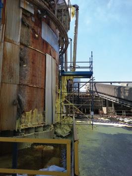
Storage tank showing severe base corrosion leading to sulfur leakage.
As an industry, we come from a decades-old culture of trust in our sulfur suppliers, traders, and the conventional standards of sulfur quality. However, this long-standing reliability is
now being challenged. With the global transition toward green energy, the sources of sulfur are rapidly changing to meet growing market demand. These new sources often differ significantly in composition, handling, and transportation standards—factors that many existing plants were never designed to accommodate.
This does not mean that existing processes cannot adapt to these new realities; rather, it highlights a persistent reluctance within the industry to recognize that adaptation is necessary.
Regular verification of incoming sulfur quality is now essential to ensure that neutralization, melting, and filtration processes perform as intended.
When such verification is overlooked, plants often receive sulfur that has been stored for extended periods under suboptimal conditions, with sampling performed either
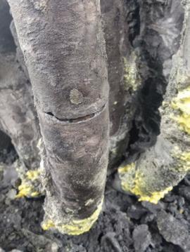
Heating coil with pipe corrosion causing steam leakage.
years earlier or from a single, unrepresentative point in the stockpile. If that sample happens to meet the expected quality specifications, the sulfur is sold, and operators assume that neutralization requirements can be calculated based solely on those parameters. In practice,
however, much of the sulfur may differ from the sample— frequently exhibiting a lower pH (higher acidity)—which leads to improper lime dosing and subsequent operational issues.
Besides the natural oxidation process, another contributing factor is the change in sulfur quality during transportation. Exposure to external environmental conditions—such as moisture, temperature fluctuations, or contamination—can alter the chemical composition of the sulfur, leading to variations in pH or increased acidity.
Regardless of the underlying cause, when sulfur exhibits a lower pH, the neutralization process remains incomplete. As a result, molten sulfur, not neutralized, continues downstream to the filtration system, where it gradually degrades filter elements, corrodes piping, and causes significant operational inefficiencies.

By the time operators notice abnormalities further down the process line, the damage is often already underway. In most cases, the plant contacts equipment suppliers, initiates audits, and conducts laboratory testing on sulfur samples, only to discover that the issue originated from an incorrect neutralization calculation. After months of equipment failures, unplanned downtime, and troubleshooting, the underlying problem is finally identified and corrected, allowing the plant to resume normal operations.
Even more concerning are cases where the supplied sulfur’s pH is so low that proper neutralization becomes impossible. Since most systems are designed to handle only a predefined lime dosing range, operators are left with sulfur that cannot be safely processed without risking severe damage to their equipment. In such situations, plants are forced to halt production, source higher-quality sulfur, or invest in upgraded systems capable of managing the new process parameters— all of which result in significant
production delays and financial losses.
At Sulphurnet we consider real world scenarios during the design process. One of the parameters in this design process is to consider the variability caused by the sulfur market. Besides incorporating a proper process design during the design phase of a plant, we also recommend all plants follow the following recommendations:
1. Remember that OPEX savings usually outweigh the savings from a “good” deal purchase of raw material.
It is common for plants to purchase sulfur from the lowest bidder, which often results in low quality sulfur that causes problems such as the before mentioned acidity.
2. Double check the storage and transportation conditions with sulfur suppliers.
Sulfur is usually purchased based on the specification sheet from the sulfur provider. However, the sulfur that is delivered to the site generally no longer
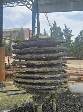
complies with these specifications. This can happen for various reasons, such as inappropriate storage and transportation. Therefore, it is recommended to thoroughly check the transportation process of the sulfur and take samples of the sulfur prior to loading in the shipping vessels.
3. Sample and test sulfur acidity.
After the sulfur is delivered, it is important to regularly sample and analyse the acid concentration in the raw material and adjust the lime dosing equipment accordingly. It is recommended to analyze the acidity of the solid
sulfur in the stockpile during every shift. After the melting tank, the acidity should be analyzed again to verify that the amount of lime added is sufficient to produce an acid-free product. Lime dosing is not just a routine step— it’s a cornerstone of process control, ensuring safety, efficiency, and profitability in sulfur melting operations.
4. Invest in automated lime dosing systems and adjust its settings.
Besides measuring the acidity inside of the sulfur it is important to adjust the quantity of lime added to the melting process. For neutralization, it is advised to use either CaO (Quick Lime) or Ca(OH)2 (dehydrated Lime). These will react with the sulfuric acid in the sulfur according to the chemical reactions below.
Ca(OH)2 + H2SO4 > CaSO4•2H2O + H2O
CaO + H2SO4 —> CaSO4•2H2O
Dehydrated lime is preferred in the process since quick lime has some disadvantages, including being a health risk, from inhalation and contact with skin.
It is also hygroscopic, forming a slimy cake when reacting with water.
What looks like basic steps in sulfur plant operations can quickly and quietly become expensive mistakes. From premature filter leaf corrosion to months of lost production, the consequences of mishandling the neutralization process go beyond replacement costs.
We’ve seen too many plants spend time ‘fixing’ equipment failures that were in fact sourcing, sampling and/or neutralization issues. So the lesson is clear: quality control starts before the sulfur even reaches the melter. Implementing regular sampling, supplier data validation, and investing in customized process design, plants can take better care of their assets, minimize downtime, and avoid multi-million dollar fixes. Get it right the first time so you can ensure long-term reliability and profitability.
For more information, please visit www.sulphurnet.com. q
By: Gary Siegel, Marketing Director, Beltran Technologies, Inc.
The current worldwide demand for pure sulfuric acid has outpaced the current supply for the chemical. The market is experiencing significant growth, driven primarily by the increasing demand from industry sectors. This demand is the result of technology advancements from industries like battery production where a higher consumption of sulfuric acid is necessary. Also, the demand for phosphate acid for fertilizers, calcium dihydrogenphosphate, and ammonium sulfate phosphates continues to grow in the agricultural farming industry.
To meet the growing demand, new sulfuric acid plants are emerging and existing plants are increasing capacity by adding new production lines to their existing plants.
Larsen and Toubro Construction, Minerals and Metals has specified four Beltran wet electrostatic precipitators (WESPs) for Hindustan Zinc’s newest sulfuric acid plant in Debari Udaipur, Rajasthan, India. Each of the WESPs, BTP-10 x 10, are configured two in parallel followed by two in series. In the sulfuric acid production line, the WESPs are positioned after the scrubber system. The number of Beltran WESPs operating at Hindustan Zinc plants for sulfuric acid gas cleaning now total 24. This by itself is a testament for the effectiveness of Beltran’s advanced WESP technology to achieve pure H2SO4 sulfuric acid.
For the purest form of market-ready sulfuric acid, an efficient sulfuric acid manufacturing process requires the strict removal of contaminants from the input gas streams, especially fine and submicron particulates and acid mists such as those emitted from metal ore roasters and smelters, petroleum refineries, and coal-fired industrial boilers. This is necessary for protecting downstream components such as catalyst beds from corrosion, fouling and plugging, as well as for preventing the formation of a “black” or contaminated acid end-product. Proper gas cleaning also results in lower maintenance and operating costs for the manufacturing plants.
The advantages of using a WESP versus other types of gas cleaning equipment is that WESPs have high efficiency collection of submicron particulate, mists, and aerosols and low-pressure loss since the internal structure is open tubes, which are not easily plugged to restrict gas flow. Another advantage of WESPs over dry ESPs, is that WESPs can remove dusts that are conductive or have high resistivity. Since a lot of metallurgical dusts have high resistivity, the wet environment of the WESP coats the particulate with moisture, which makes the dust conductive and collected with high efficiency.
WESPs operate by charging and collecting the particulate, mists, and aerosols with a corona formed by the collector surfaces and the sharp pointed discharge electrodes. High voltage power supplies charge the WESPs at high voltage, usually between 30 and 75 kilovolts, depending on the WESP design and the process gas conditions. The WESP is usually formed with a collector consisting of tubes or plates with discharge electrodes held in the center of the collector structure by a high voltage frame, supported by non-conducting insulators. Since the process gases are saturated and contain electrically conductive mists and aerosols, the insulators have to be operated dry, being purged by dry, clean, and heated purge gases, usually ambient air. The WESP can be operated by the collection of liquid acid droplets, mists, and aerosols, flushing the collector plates, or with the operation of continuous fogging sprays into the collector section. WESPs usually have deluge or wash nozzles mounted to periodically wash the WESP of solids and collected particulate, which may not be removed by the draining acid/water collected by the WESP.
While most WESPs are designed with similar technology, they are not all created equal. However, they all must
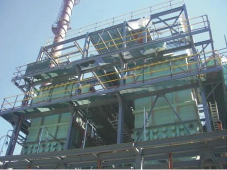
Hindustan Zinc’s newest sulfuric acid plant in Rajasthan, India, has four Beltran WESPs configured two in parallel followed by two in series.
perform by charging the input gas stream with high voltage ionizing electrode rods, collecting submicron particulate matter, and removing gas from the system. Beltran’s WESP system advantage is the engineering of the ionizing rods. Beltran WESPs are an advanced technology designed around a multistage system of ionizing rods with star-shaped discharge points. These are encased within square or hexagonal tubes that are lined with grounded collection surfaces. Beltran WESPs are engineered with advanced materials of construction that utilize the advantages of collector tubes, such as the hexagonal and square tube.
The most efficient design in terms of collection efficiency, compactness, and economic considerations is the square tube collector configuration. The square tube collector completely utilizes the cross-section of a square or rectangular vessel and can be effectively utilized in both round and hexagonal vessels. Due to the square tube’s high utilization of the vessel cross-section, it can be operated at a lower velocity so that the required tube length is lower, making it more efficient and easier to wash, since the wash sprays penetrate the collector. The high voltage frame is also more rigid, does not swing, and stays more accurately aligned, resulting in more efficient and reliable performance. Because of the shorter tube length, lower stabilizing insulators are not required, and the insulators can be mounted on the clean gas side of the WESP, reducing the requirement for heated purge air and resulting in more reliable WESP operation. Beltran WESPs can clean complex gas emissions of particulates and acid mists down to submicron scale (PM 2.5) with up to 99.9% efficiency.
The collection efficiency of the WESP varies with the size of the particulate, mist, or aerosol. Since gas phase reaction and evaporation/condensation form particles around 0.1 to 1.0 microns, considerable acid mist and particles form in this size range. As particles increase in size from the submicron range, they are more easily collected, since field charging increases. Also, as particles decrease in size from the submicron range they are more easily collected, since diffusion charging increases. Therefore, the collection efficiency curve versus particle size forms a U-shaped curve with its minimum in the submicron range. The collection efficiency is also related to the corona power of the WESP, with the minimum efficiency increasing with greater corona power. To minimize the size of the WESP and maximize operating efficiency, WESPs should be designed to maximize w, the drift velocity, or the rate at which particulate, mists and aerosols move to the collector plates.
WESP collection efficiency is increased with increasing corona power. Multi-point star discharge electrodes are
utilized to maximize corona power and WESP operating efficiency. Multi-point star discharge electrodes overcome the problems of current suppression of space charge effect, whereby the corona power is significantly reduced by the high concentration of submicron particles, mists, and aerosol present in the process gases. This reduces the corona power of the WESP operation and can lower the collection efficiency. The multi-point stars charge and repel some of the submicron particles, and then enable the next star to increase its corona power, repeating this phenomenon almost 100 times as the gases flow up the tube. This type of electrode can produce considerable efficiency in single or multiple pass WESPs, usually utilized in acid plants.
WESPs can be utilized in various configurations, such as: single WESPs; two WESPs in series; two WESPs in parallel; and multi-WESPs in parallel and two in series. Smaller gas flows are usually treated with one WESP. This also depends on the efficiency requirements; however, for smaller flows, one WESP unit can produce reliable service at 99.5%. Typically, plants have two WESPs in series so that one WESP can be washed while one operates. Sometimes two WESPs are designed to be utilized in parallel, for similar purpose. Two in series, has the advantage of the first WESP overcoming the current suppression condition, while the second WESP operates at full power. This will depend on the gas flow rate, inlet and outlet process conditions, amount of particulate, mist and aerosol at inlet and outlet, etc. Larger plants will require more WESPs in parallel and usually two WESPs in series; so one WESP can be either taken offline for washing or maintenance, or washed online.
Beltran WESP systems are built with sophisticated electronic controls linked to a close-coupled gas flow management system. This system can optimize operating parameters such as gas velocity, saturation, temperature, and corona intensity, to achieve maximum efficiency. Also, to prevent premature deterioration, critical surfaces should be constructed with advanced protective materials such as fiber-reinforced plastics (FRP) or high nickel-chromium alloys. The high-voltage insulators should be continuously purge-air cleaned to further reduce maintenance costs.
Today’s WESP systems are built of metal alloys, thermoplastic materials, thermosetting materials, and conductive graphite composite materials. Metal alloys are expensive and have extended delivery time, but their biggest disadvantage is the unreliable performance with regard to corrosion. The sulfuric acid WESP operates in highly corrosive environments, including sulfuric, hydrochloric, and hydrofluoric acid and other impurities, as well as increased temperature. Because of the high cost of more robust chrome-nickel-molybdenum alloys, like C-276, C-22, and C-2000, designers are attempting to utilize less corrosion resistant alloys like AL6XN and SMO 254, with resulting corrosion problems in some applications and conditions.
The Beltran WESP manufactured with conductive graphite composite materials have the following advantages:
• Highly corrosion resistant
• Have good mechanical properties
• Electrically conductive
• Homogenous
• Do not require water/acid film to ground WESP
• Fire retardant and thermally robust
• Cost effective
For more information, contact Beltran Technologies, Inc. at (718) 338-3311 or info@beltrantechnologies.com, or visit www.beltrantechnologies.com. q

SOUTHWEST REFRACTORY DELIVERS THE HIGHEST QUALITY ACID PROOFING, REFRACTORY, INDUSTRIAL MASONRY AND FIREPROOFING WORK.
With in-depth engineering support, meticulous craftsmanship and extensive planning down to the finest details, we’re turning industry into artistry.
AND
Computational Fluid Dynamics (CFD) has become a powerful tool for industry, allowing engineers to visualize, analyze, and optimize fluid flow behavior inside equipment before physical interventions are required. This article presents two real-world applications where CFD was successfully employed to diagnose and solve operational issues in sulfuric acid plants: (1) accelerated corrosion in an acid distribution elbow, and (2) cyclonic flow in a process stack. Both studies demonstrate how CFD can support decision-making by providing quantitative insight into flow velocity profiles, pressure gradients, and turbulence distribution. The results highlight the importance of correct model definition, mesh refinement, and the practical limitations of CFD in industrial environments.
Understanding fluid behavior is crucial to ensure safe and efficient operation of equipment. Traditionally, performance evaluations rely on empirical correlations, physical testing, or past operational experience. However, these methods often lack spatial resolution or are not feasible due to cost or safety constraints.
CFD allows the simulation of fluid motion—both liquid and gaseous—by numerically solving the governing equations of mass, momentum, and energy conservation. Through CFD, engineers can visualize internal flow patterns, identify problem regions, and test multiple design alternatives without the need for costly prototypes or field trials.
At Clark Solutions, CFD has been applied to optimize equipment geometries, improve flow distribution, and solve critical issues in sulfuric acid systems. The following sections describe the theoretical basis, methodology, and two successful industrial case studies.
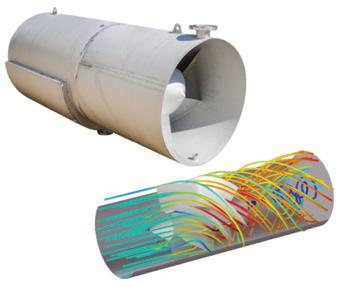
1:
CFD is based on the numerical solution of the Navier–Stokes equations, which govern the motion of fluids. These equations are nonlinear and have no general analytical solution; thus, numerical methods such as Finite Vol-
By: Eduardo Almeida, Clark Solutions, São Paulo, Brazil
ume and Finite Element techniques are employed. The process involves discretizing the geometry into small control volumes (or elements), converting the differential equations into algebraic ones.
Accuracy depends on mesh refinement: smaller elements lead to more precise results but demand higher computational power. Engineers must balance reliability and computational feasibility.
A CFD study generally follows these steps:
• Geometry simplification
• Physical model selection
• Boundary conditions
• Mesh definition
• Processing and convergence
• Post processing
The first step involves creating or importing the geometry of the system. Nonessential details—such as bolts, supports, or small gaps—are removed. Simplification reduces the number of elements and accelerates convergence, provided the model remains representative of the physical system.
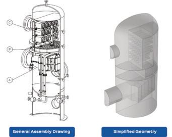
Fig. 2: A gas-liquid vessel separator geometry simplification. The equipment consists of: inlet device, mesh agglomerator, and cyclone mist eliminator. These steps were taken for geometry simplification: (a) cut off bilateral symmetry, (b) cut off liquid level not simulated, (c) walls surface with no thickness, (d) removal of fixation parts and draining tubes, (d) avoidance of any gaps.
Most industrial flows are turbulent, for which no closed-form analytical solution exists. The RANS (Reynolds-Averaged Navier–Stokes) approach is widely adopted due to its balance between accuracy and computational cost. The turbulence models most adopted are:
• k–ε (K-Epsilon): general-purpose model, robust for most flows.
• k–ω (K-Omega): better near walls but requires finer meshes.
• SST (Shear Stress Transport): combines k–ε and k–ω advantages.
Other important models are variations or improvements of the mentioned models.
Boundary conditions define the physical environment of the problem, including:
• Inlet flow rate or velocity
• Outlet pressure
• Wall properties (smooth, rough, or adiabatic)
• Fluid characteristics (density, viscosity)
• Symmetry planes or initial conditions
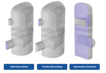
3: Some of the boundary conditions for the same geometry shown
The domain is divided into small elements—tetrahedral, hexahedral, prismatic, or pyramidal. Mesh refinement is essential near walls or regions with strong gradients in velocity or pressure. Excessively coarse meshes may yield unrealistic results, while overly refined ones lead to prohibitive computation times. The engineer’s challenge is to find the optimal balance.
CFD solves iteratively approximating the solution until reaching a defined convergence criterion. Complex geometries and refined
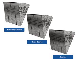
Fig. 4: Partial geometry of a radial gas-gas heat exchanger with different mesh refinement levels. The tubes are practically diamonds with the coarsest mesh and become rounder with mesh refinement.
meshes increase computational effort. In some cases, non-convergence indicates the need to revisit geometry, boundary conditions, or mesh quality.
After convergence, results are visualized as velocity vectors, pressure contours, and streamlines. Quantitative data (average velocities, pressure drops) are extracted for analysis and comparison between design alternatives.
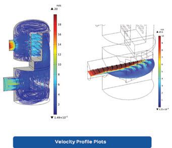
A feed elbow in the acid distributor of an interpass absorption tower experienced rapid corrosion, requiring replacement every 45–60 days. The elbow was made of cast iron, which prevents local repair. The problem originated after relocation of an orifice plate from downstream to upstream of the elbow, which was performed due to poor liquid distribution through the liquid distributor channels.
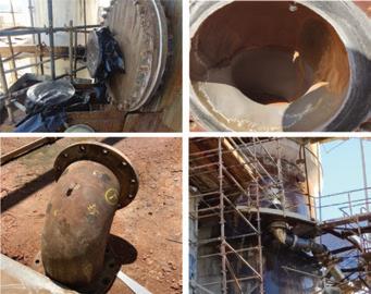
Table 1: Processing results of geometry shown in Fig. 4. Mesh Elements increase substantially between each refinement level, increasing Computational Time. Also, temperature varies representatively from “Extremely Coarse” to “Extra Coarse,” but hardly vary from “Extra Coarse” to “Coarser,” meaning that a sufficiently refined mesh has been achieved.
The working hypothesis was that the new orifice position generated high-velocity jets impinging on the inner wall of the elbow, causing erosion and accelerating corrosion.
A simplified geometry of the line segment was modeled using the k–ε turbulence model. CFD revealed high-velocity zones—up to 6.5 m/s—directly striking the elbow wall. Cast iron, although thick and corrosion-tolerant, relies on a fragile ferric sulfate layer for protection, which can be stripped by excessive velocity and turbulence.
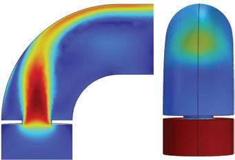
• Increasing the distance between the orifice plate and elbow by 10 inches significantly reduced velocity peaks.
• Splitting the single orifice into three smaller holes (triangular pitch) maintained the total open area but showed less improvement.
Although CFD demonstrated that relocating the orifice plate was beneficial, operational constraints prevented this change. Instead, the elbow was manufactured in CSX alloy, known for forming a passive silicon oxide layer highly resistant to corrosion and erosion.
After installation in May 2022, the test elbow performed successfully. Additional units were installed in September 2022, and inspections in 2025 showed minimal wall loss—achieving lifetimes, for now, more than ten times longer than the original cast iron elbows.
During isokinetic sampling of atmospheric emissions, inspectors observed cyclonic flow at the measurement point, located 38 meters above ground level. A flow straightener previously installed inside the stack had been removed. A non-axial flow at the sampling point invalidates emission measurements, necessitating correction.
stack axis. Higher angular deviation indicated stronger swirl. External wind interaction was also considered, as it induced asymmetrical pressure around the stack. Based on meteorological data and topographic factors, a 15 m/s wind velocity was adopted for simulation.
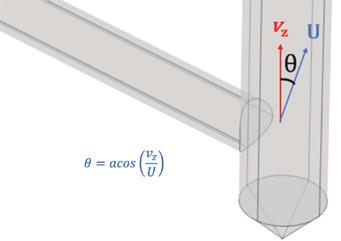
Fig. 10: Parameter to analyze velocity profile inclination, which leads to interpretation of the intensity of radial flow. Results close to zero indicate developed axial flow, which is the main objective. While higher results indicate radial flow, typical in centrifugal flow.
The model confirmed significant swirl angles at the sampling height. A rectifying device with six blades, positioned 10 meters above the gas inlet and covering 60% of the stack diameter, was proposed after simulations at different heights. New simulations showed that the device generated a short recirculation zone below it, but effectively restored axial flow at the sampling location, ensuring valid measurements.
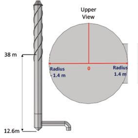
Fig. 13: Angle described in Fig. 10 is evaluated in the line that represents the chimney diameter evaluated for the sample height.

Fig. 14: Radial velocity is representative in the sample height, which hinders measurement.
2: Velocity near the wall for different acid flowrates.
Several design alternatives were simulated; two examples are presented:
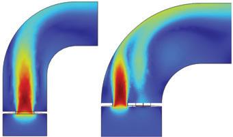
away and alternative 2 (right) velocity profile changing orifice quantity to 3 (maintaining free area) without changing distance.
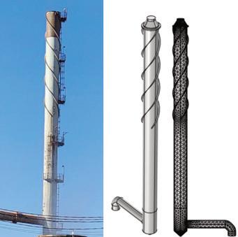
9: Chimney studied (left), geometry simplification (center) and mesh generation (right).
CFD modeling was conducted to evaluate the angular deviation of velocity vectors from the
The device was installed and solved the measurement issue.
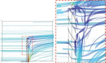
Fig. 11: Wind on the stack outlet tends to create cyclonic flow that induces the cyclonic flow inside the chimney.
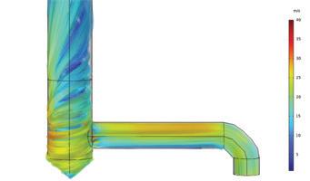
12: Cyclonic flow induced by streamlines shown in Fig. 11.
Both cases demonstrate how CFD enables visualization of internal flow phenomena that are otherwise inaccessible.
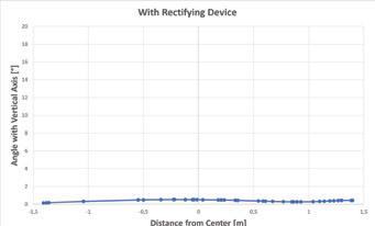
Fig. 15: Adding a rectifying device 10 meters above the chimney basis decreases the angles substantially, virtually eliminating radial flow.
wall velocity and consequent corrosion, guiding a material substitution decision.
• In Case 2, CFD confirmed the source of cyclonic flow and optimized the geometry of a correction device.
However, CFD should not be used indiscriminately. High computational cost, model assumptions, and simplifications mean that engineering judgment remains essential. Empirical correlations and experimental data should complement, not replace, CFD insights.
CFD is a powerful diagnostic and design tool for process engineers. When applied carefully—with proper geometry simplification, mesh generation, and model selection—it provides invaluable visibility into internal flow behavior, enabling better decision-making before physical modifications are made.
Table 3: Comparison between alternatives and original. Moving the orifice plate away is the best approach, yet still creates velocities above good practices for cast iron.
• In Case 1, CFD provided quantitative evidence linking orifice placement to excessive
These studies confirm that CFD can prevent costly shutdowns, extend equipment lifetime, and improve process reliability. Nevertheless, its success depends on engineering expertise, appropriate boundary conditions, and validation through operational feedback. For more information visit www. clarksolutions.com. q
By: Charles Lockert, Senior Program Director, Ohio Lumex Company
In the Fall/Winter 2021 edition of this magazine, Dan Menitti with Mississippi Lime Company (now MLC) authored an introductory article (1) that detailed the development and introduction of the first viable dew point monitor to be applied to the sulfuric acid manufacturing industry. That instrument, known to many as the Breen SA Probe, has since logged many additional years of uninterrupted operation in multiple acid plants throughout the United States. The performance of those instruments in providing early detection of moisture leaks is well documented and has been corroborated by those installations many times since then.
In 2023, the technology behind the Breen ABS probe and the Breen SA probe was acquired by Ohio Lumex, a company located in a suburb of Cleveland, Ohio. While the basic operating principles behind the technology were kept unchanged, many design improvements to the mechanical and electrical systems were implemented in 2023 and 2024. In late 2024, the Ohio Lumex Ei4200 Dew Point Monitor was released to multiple industries.
This article aims to present some of those updates and to document the performance of the Ei4200 compared with its predecessor. In addition, data from the Ei4200 running in active mode at a U.S. sulfuric acid plant is presented.

The Ohio Lumex mechanical redesign addressed several long-standing issues with the Breen system. These include:
• Change in heating system: Both the Breen SA and the Ohio Lumex Ei4200 include a supplemental heating system to provide sufficient heat at the sensor to evaporate any residual, high-boiler-temperature compound. Whereas the Breen system employed a contact system surrounding the sensor cell, Ohio Lumex employs an in-line heater that uses the “cooling air” to heat the cell. This allowed the Ei4200 to eliminate the shrouding around the sensor, facilitating on-site cell maintenance when necessary.
• Field replaceable cell: As the cell is a glass component, it is the most fragile point in the process and does, from time to time, need maintenance or replacement. By changing the mechanical design of the cell housing, the Ohio Lumex approach allows the cell to be removed, cleaned, and/or replaced in the field by plant I&C staff. The process is simple, requiring only four bolts and three wires to be addressed. The total time to replace a cell in the field should be less than one hour.
• Leak check detection: Movement of the process gas isolation valves to a location internal to the probe control box allowed a reduction in physical probe size and allows the system to be pressurized and isolated on a programmable basis to check for cell integrity and/or leakage.
• Current detection sensitivity: The key change to the electrical system focused on a dramatic improvement in current detection sensitivity. Earlier Breen designs were constrained by a 1 microamp (uA) measurement precision. This forced any monitoring scheme to look for a minimum of 2 uA to avoid noise issues and a detection threshold of 3 uA. The Ei4200 system has a measurement precision to 0.01 uA, providing two orders of magnitude improvement in condensation detection
• Remote diagnostics and optimization: The Ei4200 operating algorithms, as well as the human interface, are all implemented on an industrial Windows platform. This allows for seamless connection through cellular or Wi-Fi, in addition to the built-in Serial and Modbus communication capabilities. This provides access for Ohio Lumex to provide remote, yet handson, training and optimization without much of the cost associated with field service site visits.

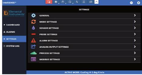
The Ei4200, since it uses the same basic sensory cell as the Breen SA, employs the same base operating approach:
1. The temperature of the cell is verified to be above the “Start Temperature.”
2. Cooling air enters the cell chamber from the backside, through a small, insulated tube.
The Ei4200 now boasts multiple installations at sulfuric acid plants, industrial dry scrubber operations, and monitoring of acid gas concentrations post-dry sorbent injection operations at coal-fired power plants.
3. Cooling air flow is controlled by a precision flow meter providing accurate temperature reduction of the sensor tip at a configurable rate.
4. When the temperature of the sensor drops below the condensation temperature of the gas, acid vapor will begin to condense on the cell surface.
5. Embedded electrodes in the sensor surface detect both the temperature of the sensor and the level of current flow on the sensor surface.
6. When the sensor surface current exceeds a configurable Delta limit, the presence of condensation is noted, and the temperature at which the Current Delta limit is exceeded is recorded.
7. At this point, the cooling air flow to the cell is restricted in a configurable fashion and the temperature of the sensor increases until it reaches the start temperature, and the process starts again.
A close-up view of the system cycle process is shown in Fig. 3.
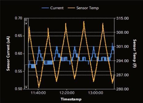
The Ei4200 now boasts multiple installations at sulfuric acid plants, industrial dry scrubber operations, and monitoring of acid gas concentrations post-dry sorbent injection operations at coal-fired power plants. For this discussion, data from a sulfuric acid plant will be presented. For reference, the plant is a sulfur burner, and the instru-
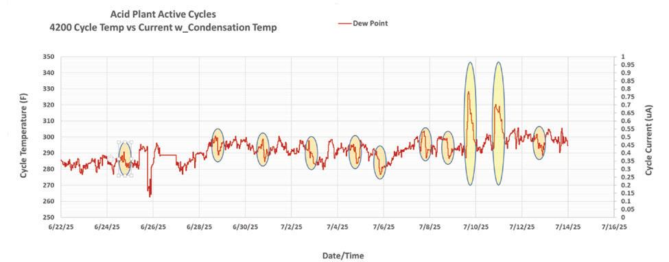
ment is located after the secondary economizer. Also, for this example, only the reported dew point (condensation point) has been reported (see Fig. 4).
There are two points for discussion here: the tall yellow highlighted ovals centered roughly around July 10th, and then a series of smaller, orange ovals that appear at semi-regular intervals throughout the operating period.
1. The plant reported that a series of major thunderstorms passed through the area over that period of time. The plant explained that the amount of rain that fell apparently overwhelmed the combustion air dryer, resulting in a higher level of moisture entering the process.
2. A rise in general-trend dew point is associated with three separate time periods.
a. 6/22 – 6/27
b. 6/29 – 7/7
c. 7/8 – 7/14
3. During these three periods, the Delta Current was being adjusted to better understand the actual temperature where condensation first appeared. Basically, the lower the Delta Current limit, the higher the reported dew point since the system sees and reports condensate earlier in the cycle.
4. What jumps out in this example is the orange ovals. In each of these ovals, a rapid drop in dew point is reported following a gradual increase. While a general fluctuation in dew point is to be expected, what is not yet explained is why these dramatic drops in dew point
occur and what meaning/value it can provide to assist plant operations in improving yield and/or reliability.
Some stated observations:
1. The current measurement process has been wildly successful. Measuring deposition-based currents with granular readings of 0.01 uA allows significantly faster cycles with significantly less material buildup and long-term corrosion.
2. However, being able to read information at sub-micro amp levels has revealed some liquid-gas interactions that were not apparent with the much higher reading Breen system.
3. It is anticipated that an Ei4200 will operate in Active Mode within the duct of a sulfuric acid plant for at least 12 months. At that point, a simple cell replacement should offer another 12 months of operation with maintenance costs limited to onsite plant staff.
4. We look forward to continuing to work with forwardlooking operations to identify the basis for the observed changes in Ei4200 readings and identifying potential changes to sulfuric acid plant operation that can be of long-term benefit.
For more information, visit www.ohiolumex.com. q
References
1. “The latest in sulfuric acid plant process gas dew point/moisture leak detection,” Daniel T. Menniti, Director of Business Development, Mississippi Lime/ Breen, 3870 S Lindbergh Blvd, St. Louis, MO 63127
Industry insiders and their families gathered at a new location, Island Grand at the TradeWinds Resort in St. Pete Beach, Fla., June 6-7 for the AIChE Central Florida Chapter’s 48th Annual International Phosphate Fertilizer & Sulfuric Acid Technology Conference and Exhibition. Colleagues from around the globe gather each year to share their ideas concerning chemical process technology, specifically the production of phosphoric acid, phosphate fertilizers, and sulfuric acid. This year’s event also included the 27th annual Sulfuric Acid Workshop, moderated by Rick Davis of Davis & Consulting Inc. and Steve Puricelli of EXP.
Friday, June 6, kicked off with an overview of this year’s sulfuric acid workshop topic: “Troubleshooting of Sulfuric Acid Plants.” Presenters focused on various aspects of troubleshooting and methods to determine the source of performance issues of acid towers, converters, hydrogen buildup, pressure drop, acid coolers, NOx, and catalyst.
Sulfuric Acid Workshop presentations included:
–“Sulfuric Acid Troubleshooting,” by Nick Moore, Elessent Clean Technologies
–“Troubleshooting Sulfuric Acid Plants–Details Matter,” by Herbert Lee, Worley Chemetics
–“Troubleshooting Some H2SO4 Plant Mist Eliminator Issues,” by Graeme Cousland, Begg Cousland Envirotec Ltd.
–“Catalyst Appearance,” by Bill Goodell, Topsoe
On Saturday June 7, attendees perused exhibitions and attended one of two concurrent sessions: Phosphate Technology and Sulfuric Acid Technology. Presentations for the sulfuric acid session included:
—“Optimizing Converter Performance with Catalyst Solutions,” by Helen Cardwell, Elessent Clean Technologies
—“You Can’t Always Get What You Want: A Value Engineering Story,” by Steve Puricelli and Guy Cooper, EXP
—“Acid Plant Ducting Design,” by Randal Sarrazin and Werner Vorster, NORAM Engineering & Constructors
—“Improving Energy Recovering and Unlocking Value with MECS HRS Technology, by Colin Shore, Elessent
Clean Technologies
—“Towards a New Level in Performance with Selection of Catalyst Geometric Shape,” by Allison Belgard, BASF
–“Using Alternative Materials in High Corrosion Zones of an Adiabatic Gas Cooler,” by Ethan Schrader and Joan Bova, CG Thermal
In addition to family-friendly hospitality suites and dinners with friends old and new, attendees and their families enjoyed a spouse brunch, an interactive children’s science party, musicians, magic, face painting, and karaoke.
Next year’s convention, the 49th Annual International
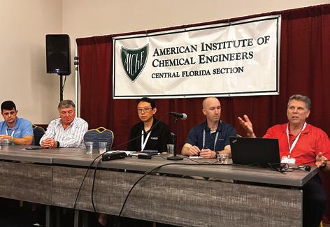
Phosphate Fertilizer & Sulfuric Acid Technology Conference, will be held at the Island Grand at the TradeWinds Resort on St. Pete Beach, Fla., on Friday, June 5th and Saturday, June 6th. For more information, please visit the event’s website: www. aiche-cf.org. q
Sulfuric acid producer, Ecoservices, gathered its maintenance and technical personnel along with trusted suppliers at a Maintenance & Reliability Seminar, which took place over two days last June in downtown Houston. Coordinated by Sulfuric Acid Today, the impetus for the meeting was to improve overall reliability across the company’s many manufacturing sites.
“The goal of the meeting was for key personnel to review best maintenance practices and new innovations,” said Gavin Floyd, Senior Director of Technical Group, Ecoservices.
Included were maintenance personnel, internal technical staff, as well as trusted vendors and contractors. A key difference from other internal meetings was the addition of maintenance staff.
“Generally, maintenance folks are left out of internal technical meetings even though they are often the onsite decision makers,” Floyd said.
The 40 Ecoservices personnel in attendance were maintenance and reliability supervisors; engineering staff; as well as in-house technical staff, subject matter experts, and asset utilization personnel. These individuals represented manufacturing sites in Baton Rouge, LA; Bay-
town, TX; Dominguez, CA; Hammond, IN; Houston, TX; Martinez, CA; Orange, TX; and Waggaman, LA.
Ecoservices also invited some of their most trusted technology providers and contractors to present topics of special interest to the company. These providers and their presentations included:
• VIP International: Common maintenance issues in acid plants
• Southwest Refractory: Refractory
• Acid Piping Technology: Ductile Iron best practices
• RTConsults: FRP piping inspection
• StraightLine: Insulation
• Nalco: Cooling Water
• Central Maintenance & Welding: Fabrication, welding, and expansion joints
• Worley Chemetics: Acid plant inspections
The seminar emphasized the importance of problemsolving through broad networking, both within internal channels and with trusted suppliers.
Floyd stated that while this internal seminar had favorable feedback from Ecoservices’ personnel, he mentioned the importance of still attending the Sulfuric Acid Roundtable.
Ecoservices recently conducted a Maintenance and Reliability seminar for 40 personnel in Houston, Texas.
“The professionals you meet at the Sulfuric Acid Roundtable is the best way to get offline help with the idea that if you help others in the industry, one day they will help you,” said Floyd.
The seminar included networking time during lunch and breaks; and the event concluded with a group dinner at a popular seafood restaurant.
For more information on conducting a Maintenance & Reliability seminar for your manufacturing company, please contact Kathy Hayward, Sulfuric Acid Today, at (985) 807-3868 or kathy@h2so4today.com. q
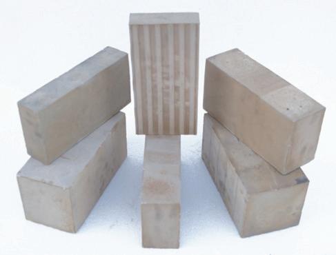
From our strategic location in Houston, TX, we are able to supply a variety of brick shapes (straights, arches, wedges, keys) and sizes from stock for immediate purchase.
Please reach out to us for technical data and pricing. Samples available upon request.
Meeting ASTM C279 standards for use in new construction and refurbishment of existing structures in sulphuric acid plants including towers, process vessels, floors, sumps, pits, etc.
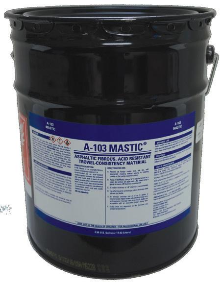
Industrial Linings for Sulphuric Acid Plants. Absorption Towers, Pump Tanks, Sulphur Pits, Secondary Containment, Acid Resistant Linings.
Acid Brick, Acid Resistant Mortar, Membranes, Carbon Brick, Polymer Concrete, Refractories, Teflon, Ceramic Paper and Blanket, Ceramic Rope, Borosilicate Block
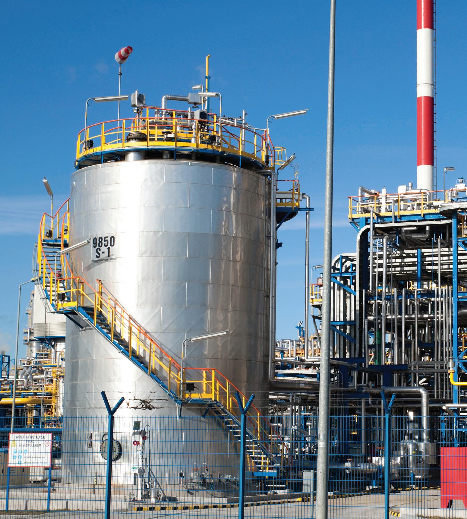
A-103 Mastic® is Still Available and in Stock in warehouses in USA and Canada. Madefromtheoriginalrecipe.
When your plant has a product that has proven successful for over forty years, why change? With this in mind, Alphatherm Inc. purchased the recipe of Pecora A-103 Mastic® to keep this integral piece of the Sulphuric Acid Tower lining system intact. Made from the same ingredients with A DECADES OLD RECIPE, A-103 continues to be the workhorse membrane in Acid Plants worldwide.
This is THE ONLY A-103 Mastic ® made with the original Pecora recipe.
A-103 MASTIC is a registered trademark of Alphatherm Inc.


From left, Yusuf Koseoglu, Iiknur Koseoglu of Weir, Graeme Cousland of Begg Cousland Envirotec, Monica Turner, Mhairi Murphy of Begg Cousland Envirotec, Collin Bartlet of Metso, and Ricky Jaswal of Weir attended the Weir Customer Appreciation Dinner at Coconut Charlie’s during the AIChE conference.


Enjoying the Customer Appreciation Ballgame at the Astros game are, from left, Cindy Milaszewski, Jarrad Garrison of Ecoservices, Laurie Garrison, Lupe Juarez, Angie Cruz, Brenda Juarez, Matias Juarez of Ecoservices, Meredith McBurnett of Ecoservices, and Mike Milaszewski, of Ecoservices.


Silva, Herbert Lee, and Bob Whitters.


Howard Tenney of Tenney & Company, left, visits with Jenifer Ben-Shoshan and Eli Ben-Shoshan of MECS/Elessent Clean Technologies during their Customer Appreciation gathering at the Astros ballgame.


Ian Legg of Central Maintenance & Welding and Tiffany Legg visited John Horne of MECS/Elessent Clean Technologies during Elessent’s hospitality suite at the conference.



Karaoke at the MECS/Elessent Hospitality Suite was a crowd favorite. Singing “Sweet Caroline” were, from left, Jack Harris of VIP International, John Horne, John Burk, Colin Shore, Trevor Weststeyn, Marcelo Kascheres of MECS/Elessent, and Howard Tenney of Tenney & Company.


Topsoe held a customer dinner with attendees, from left, Reed Bond of J.R. Simplot, Connor Reece and Tony Silva of Worley Chemetics, Patrick Polk of Topsoe, Emily Goodell, Bill Goodell of Topsoe, Erin Johnson of J.R. Simplot, and Lyndsie Holden of J.R. Simplot.


Clean Technologies


Enjoying dinner at Coconut Charlie’s were, from left, Daniel Tate of Ecoservices, Guy Cooper of EXP, Kevin Bryan of Lithium Americas, Cindy and Howard Tenney of Tenney & Company, Jack and Becky Harris of VIP International, Kathy Hayward of Sulfuric Acid Today, Patti Rubin, and Steve Puricelli of EXP.

the


Weir Lewis Pumps, Acid
Technology, and



Appreciation

and
the


The Sulphur + Sulphuric Acid conference continues to be an essential annual forum for the global sulfur and acid community to learn, connect, and do business. Knowledge sharing is at the event’s core, via the respected dual-streamed technical program and connections between the attending industry experts and solution providers. The conference takes place November 3-5, 2025 at the Marriott Waterway Hotel in The Woodlands, Texas. This year, you can expect an expanded market outlook agenda featuring expert insights from CRU’s analysis teams on major supply and demand markets, including sulfur and sulfuric acid, as well as additional industry updates from key
providers serving the sulfur and sulfuric acid industries.
For more information, visit events. crugroup.com/sulphur/home.
The 18th CRU Phosphates Conference will be held in Paris, France, April 13-15, 2026 at the Paris Marriott Rive Gauche Hotel.
With its unique combination of strategic insights from industry leaders and technical and operational developments, CRU Phosphates + Potash provides a welcome opportunity for the phosphates and potash communities to reconnect in person for important discussion, debate,
Plans are underway for Sulfuric Acid Today magazine’s conference, Sulfuric Acid Roundtable (SAR). The 2026 event will take place April 7-10 in Orlando, Florida, at the Omni ChampionGate. As in years past, sulfuric acid producers and leading technology companies will gather to discuss best practices for maintenance, operations, production, and safety. Panel discussions and co-sponsor booths will provide more opportunities for information sharing, while social events will ensure that participants get to enjoy the beautiful area while building relationships that promote beneficial business exchanges in the future.
Fertilizer and Sulfuric Acid Technology Conference from June 5-6, 2026, once again at the TradeWinds Resort in St. Petersburg Beach, Florida.
Each year for the last 48 years, members of the AIChE Central Florida Section and colleagues from all over the world have gathered to share their ideas concerning chemical process technology, specifically the production of phosphoric acid, phosphate fertilizers, sulfuric acid and other related topics. The convention provides ample opportunity to relax with friends and family, enjoy good food, and have fun.
This year there will be several workshops held on Friday, June 5, including the Bi-Annual PE Laws, Rules, and Ethics Workshop as well as a session relating to
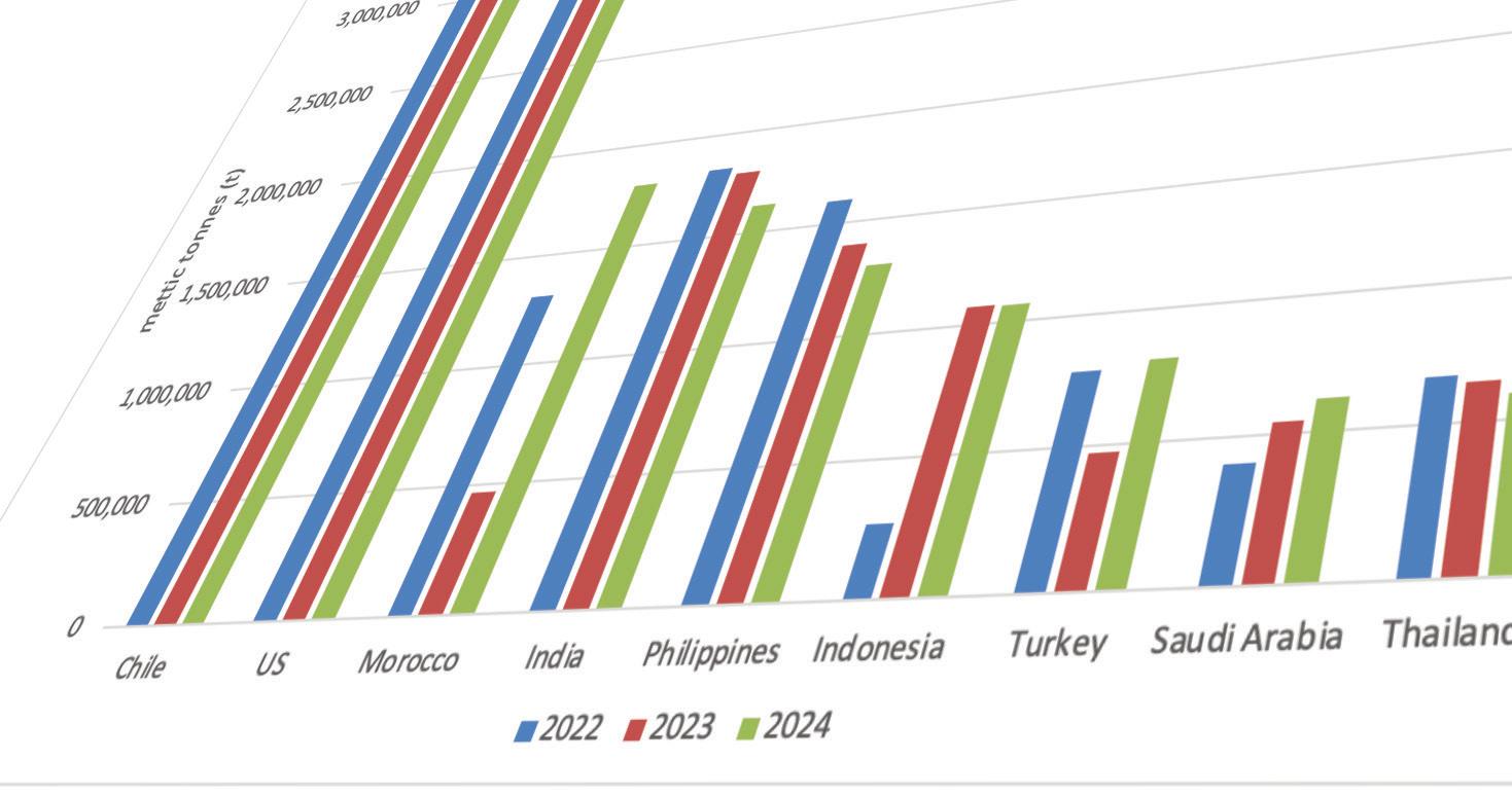




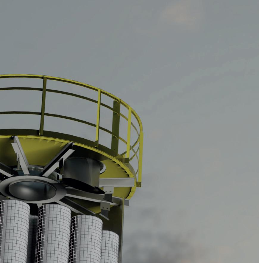
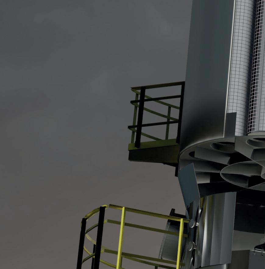
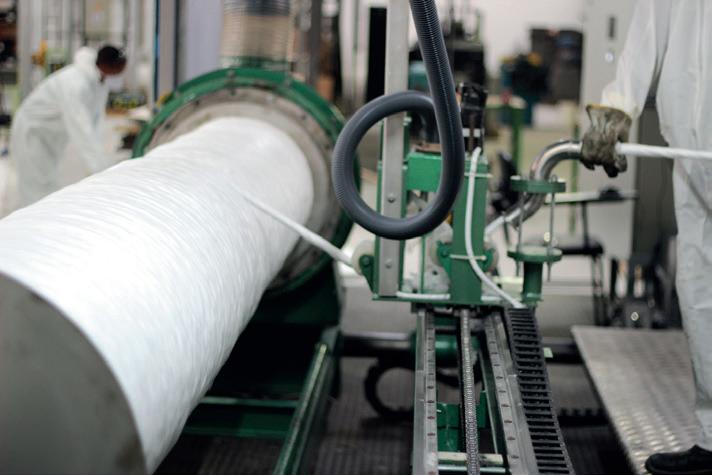
Submicron mist removal with Fiberbed technology

Fiberbed® mist eliminators remove submicron droplets through Brownian di usion and extended residence time in dense fiber media.
clarksolutions.com.br
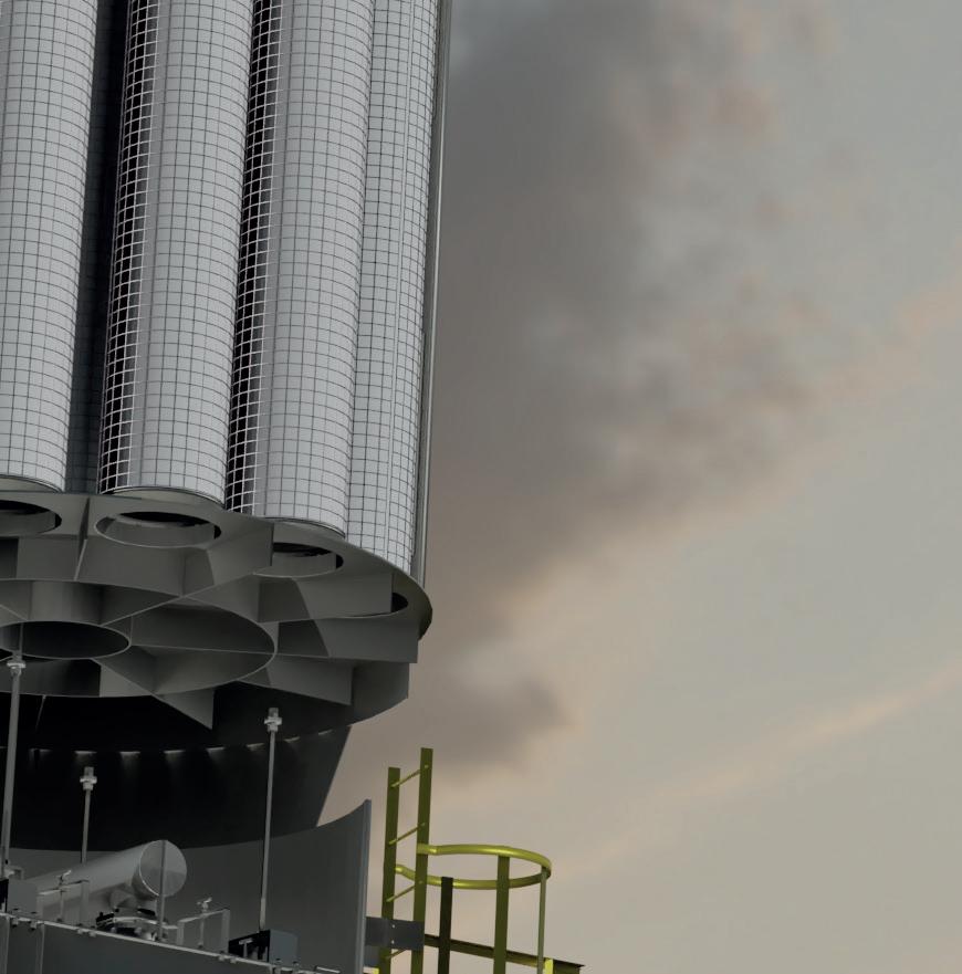
Repack available
In-house production
Reutilize existing cages and replace the filtering media
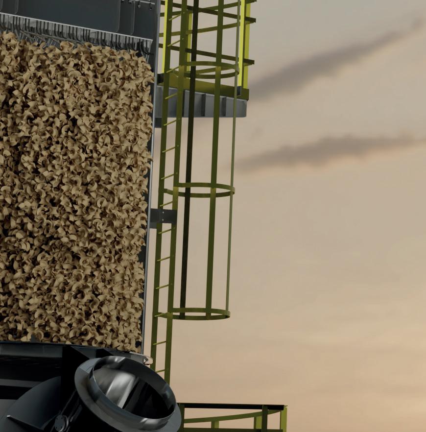
Material and design options
Including plastic versions for corrosive applications
With over 130 years experience, LEWIS ® pumps and valves are engineered with genuine LEWMET alloys, meaning they provide better corrosive resistance than anyone else. Our team is focused on one thing, and one thing only, creating the most durable products in the world. It’s no surprise we’re market leaders, there’s just nothing as strong as Lewis pumps and valves.

Learn more at onlylewis.weir
