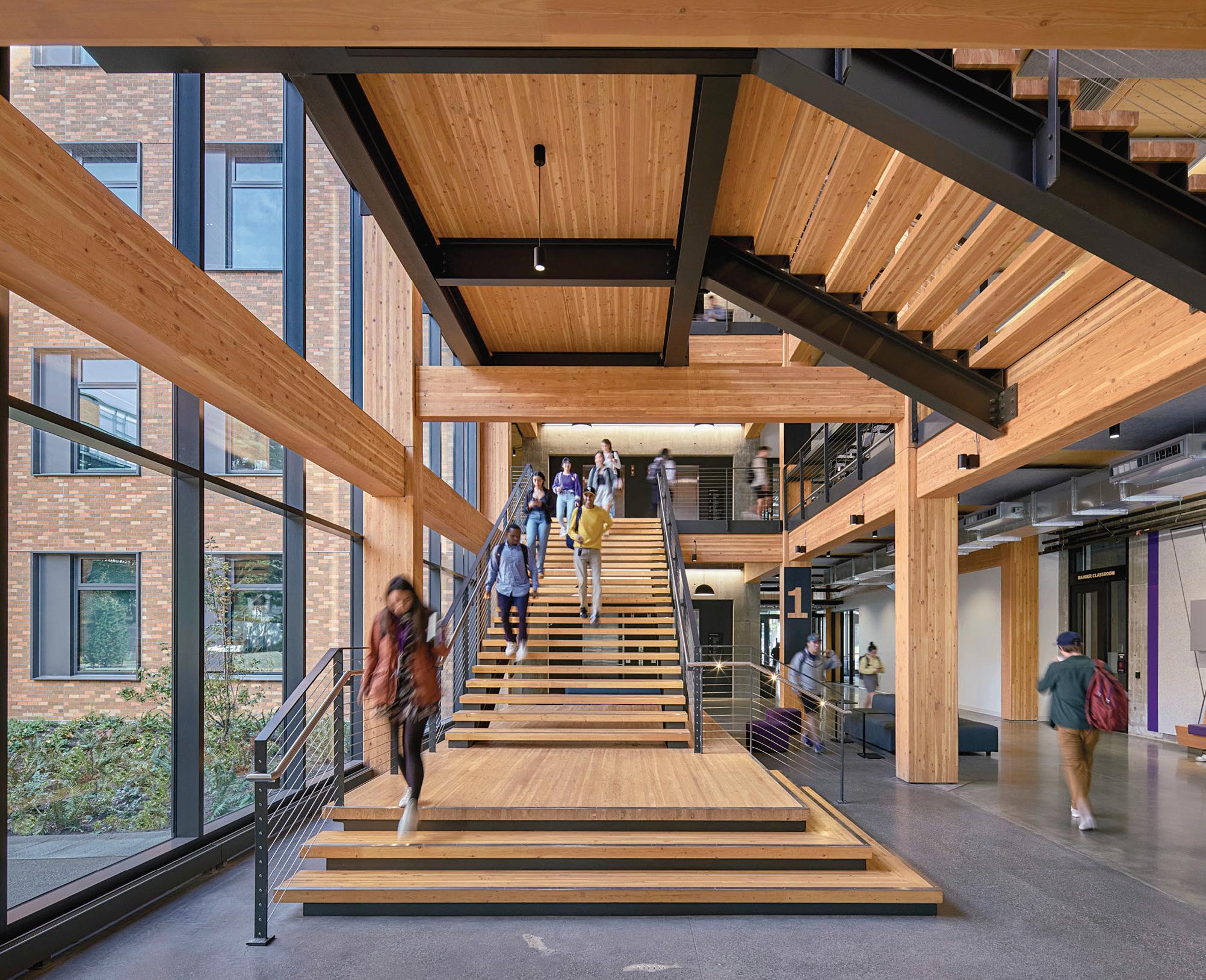
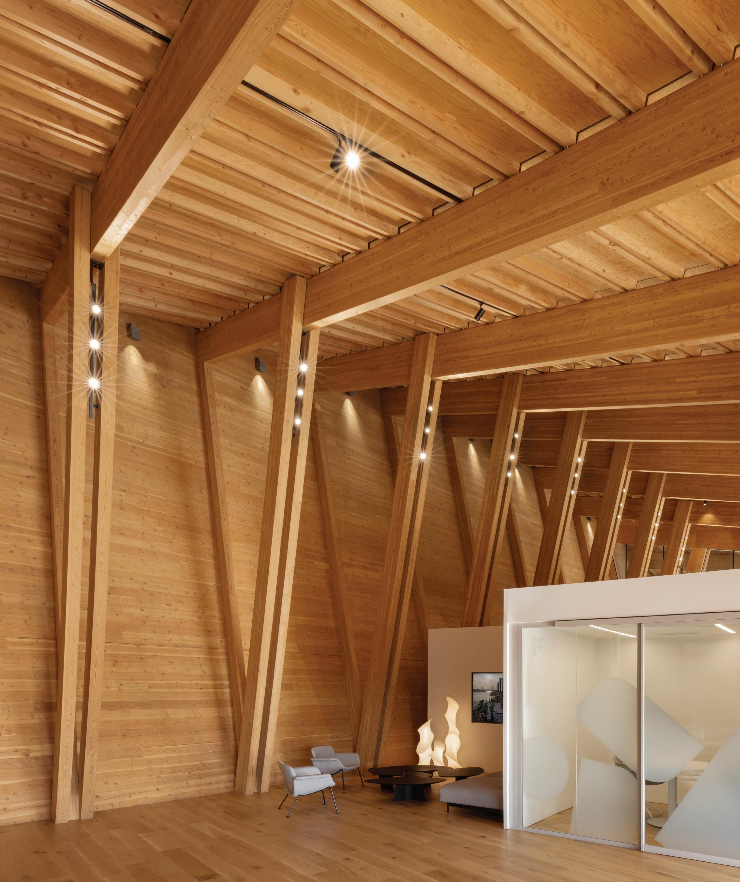


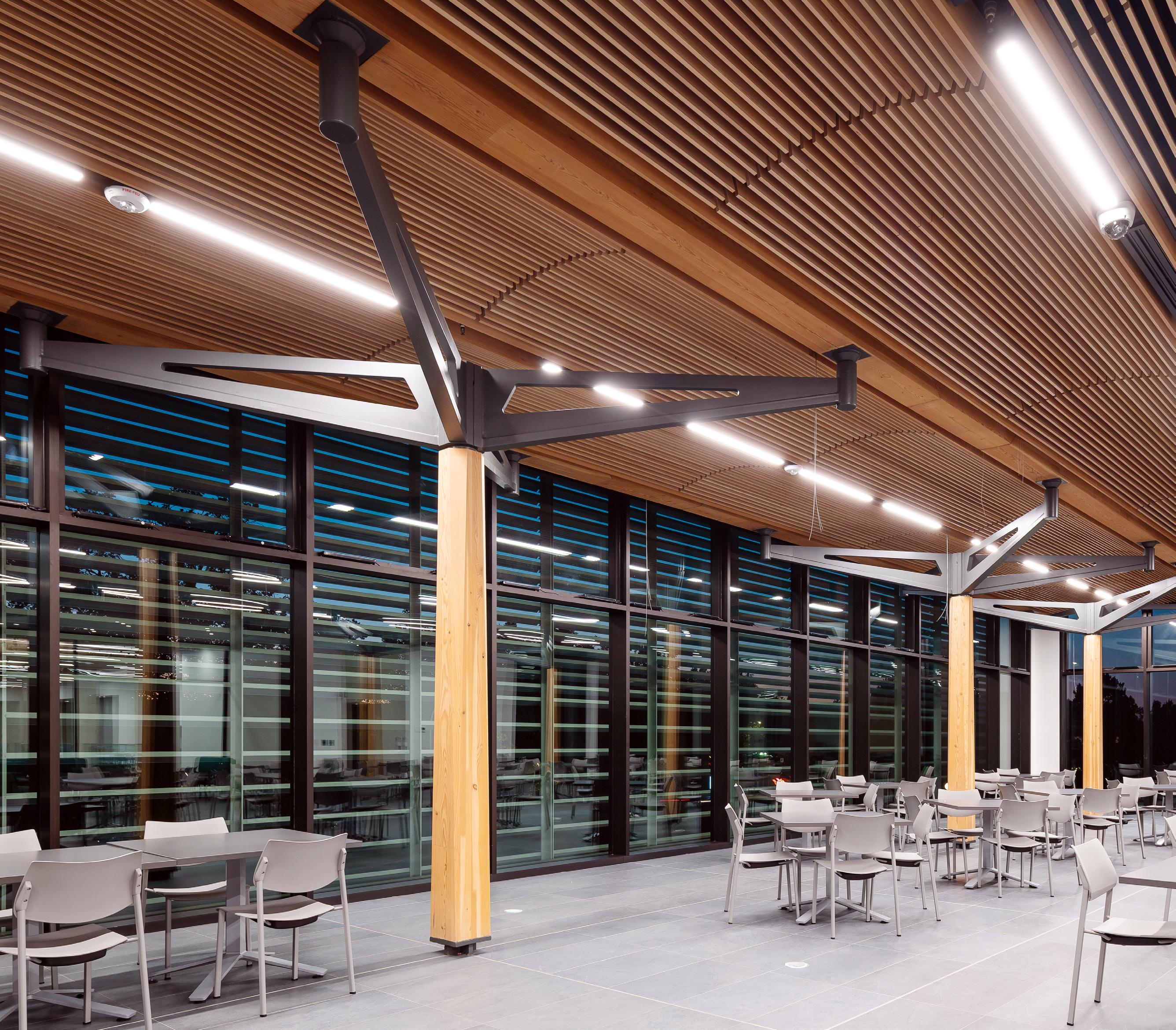

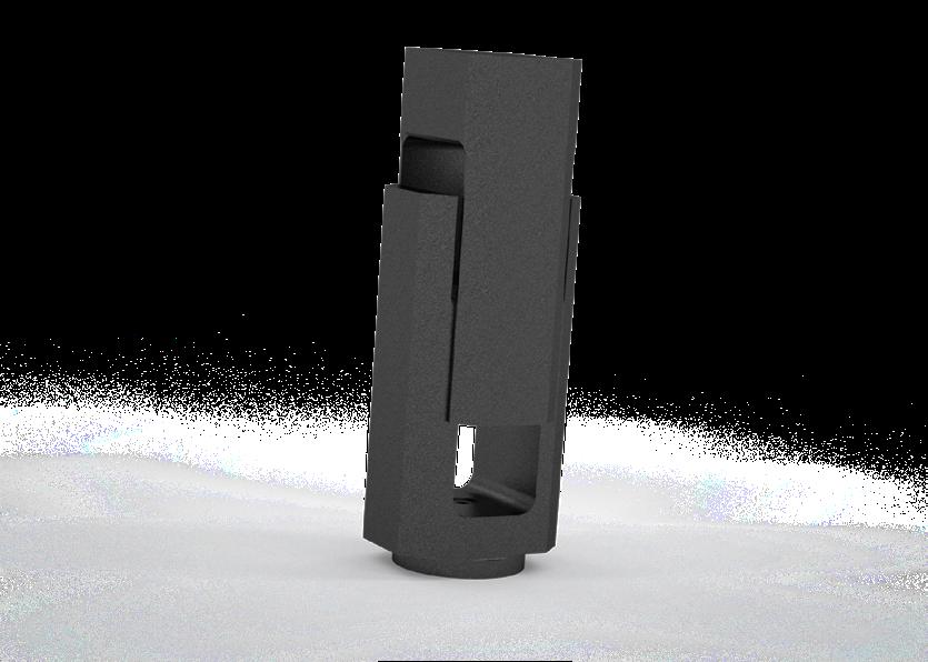
CAST CONNEX ® custom steel castings allow for projects previously unachievable by conventional fabrication methods.
Innovative steel castings reduce construction time and costs, and provide enhanced connection strength, ductility, and fatigue resistance.
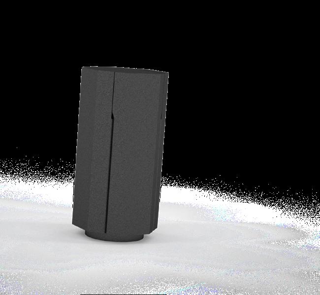
Freeform castings allow for flexible building and bridge geometry, enabling architects and engineers to realize their design ambitions.
Custom Cast Solutions simplify complex and repetitive connections and are ideal for architecturally exposed applications.


UNIVERSITY OF VICTORIA, STUDENT HOUSING & DINING, BC
Architect: Perkins&Will
Structural Engineer: Fast+Epp
Steel Fabricator: George Third & Son Ltd.
Photography by Brett Ryan Photography
subscriptions@structuremag.org
Chair John A. Dal Pino, S.E. Claremont Engineers Inc., Oakland, CA chair@STRUCTUREmag.org
Kevin Adamson, PE Structural Focus, Gardena, CA
Marshall Carman, PE, SE Schaefer, Cincinnati, Ohio
Erin Conaway, PE AISC, Littleton, CO
Sarah Evans, PE Walter P Moore, Houston, TX


May 2025
Issue Available Only at
Publication of any article, image, or advertisement in STRUCTURE® magazine does not constitute endorsement by NCSEA, CASE, SEI, the Publisher, or the Editorial Board. Authors, contributors, and advertisers retain sole responsibility for the content of their submissions. STRUCTURE magazine is not a peer-reviewed publication. Readers are encouraged to do their due diligence through personal research on topics.
ADVERTISEMENT–For Advertiser Information, visit STRUCTUREmag.org

Linda M. Kaplan, PE Pennoni, Pittsburgh, PA
Nicholas Lang, PE Vice President Engineering & Advocacy, Masonry Concrete Masonry and Hardscapes Association (CMHA)
Jessica Mandrick, PE, SE, LEED AP Gilsanz Murray Steficek, LLP, New York, NY
Brian W. Miller
Cast Connex Corporation, Davis, CA
Evans Mountzouris, PE Retired, Milford, CT
Kenneth Ogorzalek, PE, SE KPFF Consulting Engineers, San Francisco, CA (WI)
John “Buddy” Showalter, PE International Code Council, Washington, DC
Eytan Solomon, PE, LEED AP Silman, New York, NY
Executive Editor Alfred Spada aspada@ncsea.com
Managing Editor Shannon Wetzel swetzel@structuremag.org
Production production@structuremag.org
Director for Sales, Marketing & Business Development
Monica Shripka Tel: 773-974-6561 monica.shripka@STRUCTUREmag.org


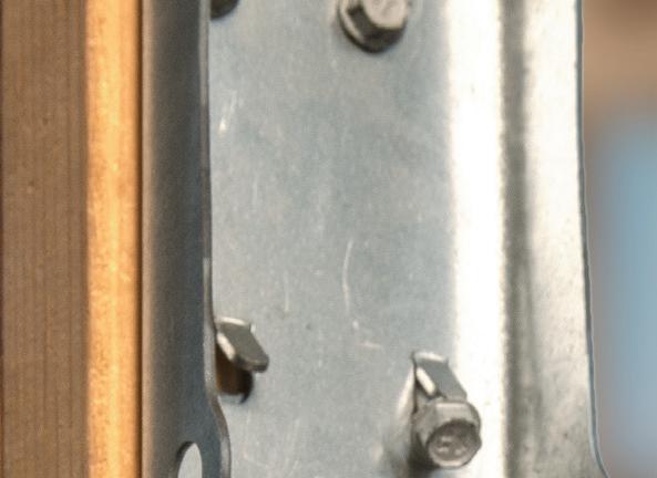
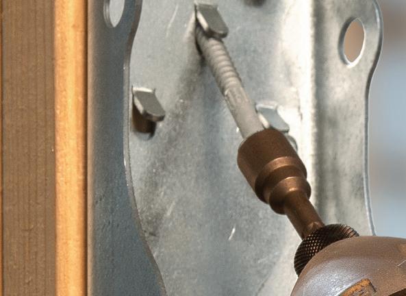
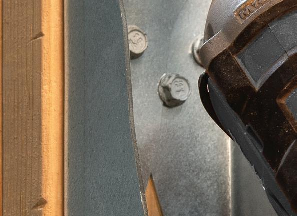
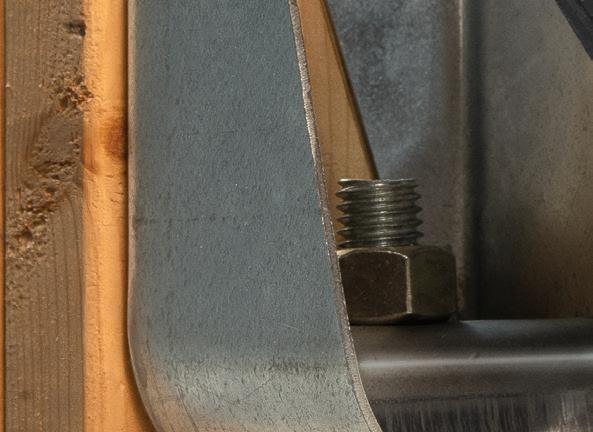









Introducing the HDUE ™ holdown from Simpson Strong-Tie Engineered for higher loads, our new holdown can be specified for isolated point loads, horizontal loads and vertical loads. It’s ideal for shearwalls and other applications in multistory structures with many windows and expansive openings. The patent-pending HDUE has an extruded seat and overlapping back plate for added strength. Plus, for higher loads in the four largest sizes, angled and perpendicular fastening engage the screws both in tension and in shear. As a one-to-one replacement to our HDU, the HDUE is code listed and tested per AC155. It’s fast to install, available in a range of sizes, and backed by our expert service and support. Learn more at go.strongtie.com/hdue or call (800 ) 999-5099.
By Jamie Pobre Sullivan, P.Eng, SE Pioneering the Future of Mass Timber at the British Columbia Institute of Technology With Wood/Steel Hybrid Construction
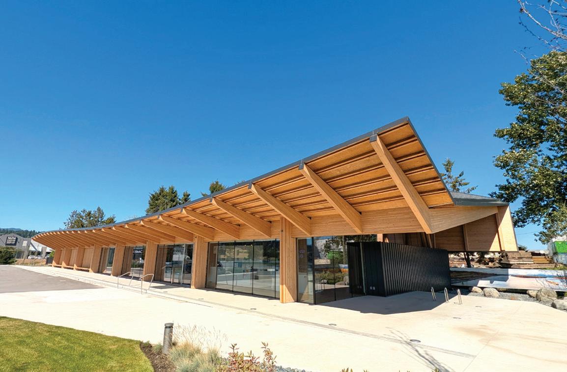

By Lukas Gispert, B.Eng., Sahar Barzani, M.Arch., Lucas Epp, PE, P.Eng.
The Fraser Mills Presentation Centre in Greater Vancouver is an exhibition of mass timber engineering.
By Carlos Moscoso del Prado Gredilla and Lynn Williams
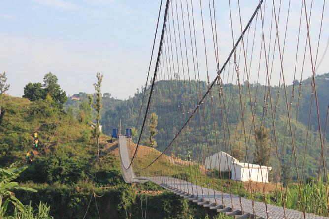
The Muregeya Trail Bridge is a success story on overcoming engineering challenges and a lifeline for the area’s population.
By Donald Harvey, PE; Namratha Kondam, EIT; Blake Larsen, PE; and Michael Monks
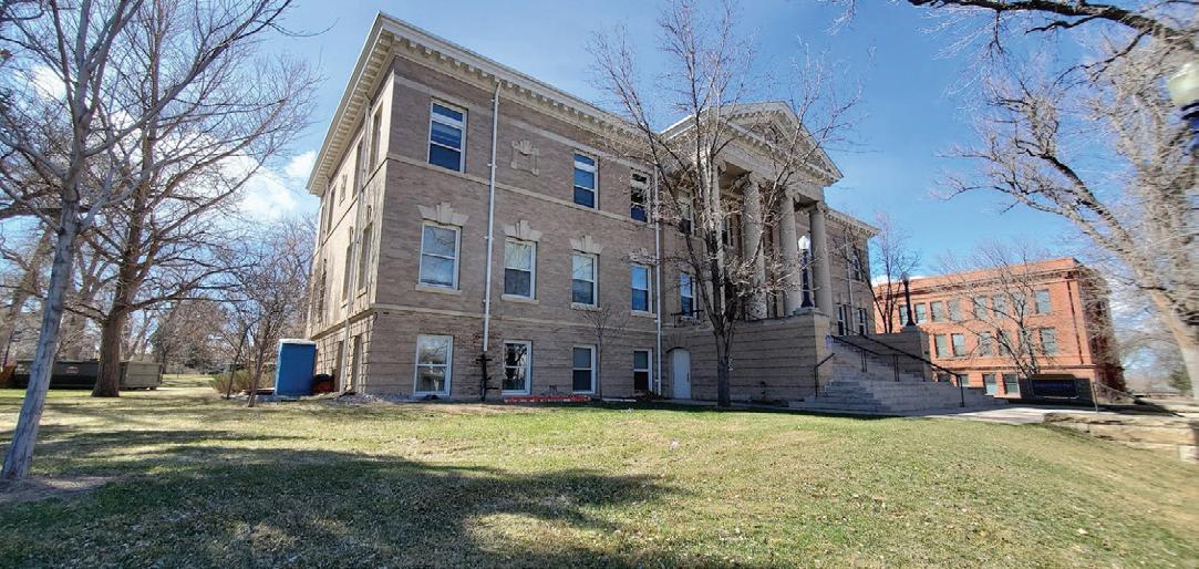
After an SUV damaged the wall of a historic masonry building on a college campus, innovative techniques were used to evaluate the damaged wall conditions and carefully provide temporary support during reconstruction operations.









Leveraging the USIBD’s Updated LOA Specification to Enhance Structural Engineering Projects By John M. Russo, RA
Structural Design
How to Prevent Progressive Collapse & Catastrophic Failure of Structures Due to Explosions
By Prof. Dr. Ibrahim M. Metwally, Ph.D., PE, M.ASCE
Seismic Retrofit Ordinances Part 4 By John DalPino
InSights
Bridge Construction With Structural Lightweight Concrete: Material Properties, Performance, and Value By Michael Robinson
Historic Structures
Fort Madison, Iowa 1888 By Dr. Frank Griggs, Dist. M. ASCE
InFocus
From Intuition to Algorithmic Inference By Danny Smyl, Ph.D, PE
By Dong Han, Ph.D; Lori Koch, MS, PE; Tyler A Davis, Ph.D
Accountability: The Role of California SB
and SB 721 in Exterior Elevated Element Safety
By Zander Danto, PE, and Paul Cordova, Ph.D, SE
Shoring Considerations in Existing Buildings
By Ezra B. Arif Edwin, SE; Kevin Conroy, SE, PE, P.Eng; and Brett Holland, Ph.D, PE, SE


By John M. Russo, RA
Accurate documentation of existing conditions is critical for successful structural engineering, especially when working on renovation projects. The U.S. Institute of Building Documentation (USIBD) has addressed this need with its recently updated Level of Accuracy (LOA) Specification v3.1, now available in its new Education Center. This document provides a comprehensive framework for specifying the required accuracy of building documentation projects, ensuring clarity and alignment among all stakeholders. For structural engineers, the LOA Specification is an indispensable tool for managing project expectations and achieving precise results.
The whole reason the LOA Specification was created was that there were no recognized standards for defining accuracy in building documentation. In my own practice, I often struggled to communicate and define accuracy on projects. I found that this issue was widespread—architects, engineers, and service providers alike faced challenges in determining what level of accuracy was appropriate. I recall one client confidently stating that they could achieve 1mm accuracy using a handheld laser range finder and therefore expected that accuracy level across the entire project. This reflected a fundamental misunderstanding of how accuracy is influenced by tools, methodology, and process.
Accuracy isn’t just a number—it’s an understanding of how error accumulates and how specifications should account for real-world conditions. The LOA Specification was born out of necessity, providing a shared language to prevent miscommunication and unrealistic expectations.
One of the most common debates around accuracy specifications is cost. Higher accuracy requirements can drive up costs significantly, yet clients unfamiliar with the realities of data collection and processing often fail to recognize this. Educating stakeholders about the cost implications of higher accuracy is essential—but ironically, time spent on education itself adds cost to a project. While it may seem logical to strive for the most accurate data possible, there is always a point of diminishing returns. I always start by asking, “What is the reason you think you need to achieve that level of accuracy?” This question gets to the heart of my philosophy: Intent defines process. Understanding the intended use of the data allows us to design an appropriate approach that meets project needs without unnecessary expense.
There’s a big difference between needing precise millimeter-level accuracy for prefabricated steel connections versus documenting a general space for planning purposes. Specifying accuracy beyond what is actually necessary can lead to overspending. The question then becomes: When is good enough, good enough?
The LOA Specification works in harmony with the BIM Forum’s Level of Development (LOD) Specification, which focuses on the detail and completeness of building models. While LOD addresses the content and usability of BIM models, LOA establishes the accuracy of the underlying data used to create those models. Together, these specifications form a powerful combination for structural engineers who rely on precise, reliable information to make critical decisions. Consider a renovation project involving seismic retrofitting. The LOD Specification can guide the modeling team in creating a detailed representation of the building’s structure, while the LOA Specification ensures that the underlying measurements are accurate enough to support the design. This integrated approach reduces uncertainty, streamlines collaboration, and minimizes risks.
The LOA Specification is now in its fourth publication, spanning over ten years. The USIBD has seen widespread adoption of the standard across the globe, but the question remains: Is the industry ready to fully embrace the USIBD’s LOA as a standard and incorporate it into project specifications and contracts? Many firms use the LOA informally as a guideline, but until it becomes a standard contractual requirement, variations in expectations and misunderstandings will persist. Adoption of LOA in formal project documentation would reduce inefficiencies, provide clarity, and ensure that project teams are aligned on accuracy expectations from the outset.
By not addressing accuracy in project specifications and contracts, stakeholders leave themselves exposed to unmet expectations and potential project disputes. Defining intent early

and crafting a specification that provides clear guidance on required accuracy— and nothing more—is crucial. When we all speak the same language, we are more likely to understand each other and minimize costly rework.
To help professionals fully understand and implement the LOA Specification, the USIBD now offers on-demand training and certification through its Education Center. These courses provide structural engineers and other industry professionals with the knowledge and skills needed to apply the LOA effectively in their projects. By earning certification, engineers can demonstrate their expertise in building documentation standards and enhance their professional credibility.
The updated LOA Specification represents years of industry expertise and leadership. As chair of the LOA Subcommittee, I have been proud to work alongside our vice-chair Prof. Dr. Christian Hesse and dozens of other industry leaders to develop the LOA Specification helping to bring a much-needed tool to building documentation standards and fostering collaboration across the AEC industry.
Structural engineers face unique challenges when designing for renovation projects and working with existing conditions. The USIBD’s LOA Specification v3.1 provides a vital tool for addressing these challenges, offering a clear framework for specifying accuracy requirements and ensuring the reliability of building documentation. By complementing the BIM Forum’s LOD Specification and promoting effective collaboration, the LOA sets a new standard for precision and efficiency. To learn more, download the LOA Specification for free and explore training opportunities at the USIBD’s Education Center at usibd.org/. ■
Bradford K. Douglas is the American Wood Council’s (AWC) Vice President of Engineering. He holds a bachelor’s degree in agricultural engineering from Virginia Tech and is a licensed professional engineer. Douglas has worked for AWC for 38 years and previously worked for the Southern Pine Inspection Bureau. He oversees AWC’s standards development program and serves on several standards development committees of other organizations, including ASTM, American Society of Civil Engineers (ASCE), U.S. Federal Emergency Management Agency’s Building Seismic Safety Council (BSSC), and the International Code Council (ICC), addressing proper design of wood buildings for exposure to fire and structural loading including high wind and seismic loads.
STRUCTURE: Why did you decide to enter the field of structural engineering?
Douglas: Growing up on a small farm in Virginia, I was exposed to a lot of situations that allowed me to apply practical problem-solving. When I graduated high school, I knew I wanted to be an engineer, but I was not sure which type. I had experience working with my dad and uncle to construct farm buildings, operating and repairing farm equipment, wiring farm buildings, installing and repairing plumbing (usually when it was very cold), and a whole host of other hands-on structural and mechanical experiences. Entering college at Virginia Tech, the Agricultural Engineering program allowed me to study the engineering aspects of each of these areas. As my engineering studies progressed, I found myself especially drawn to engineering mechanics and structural engineering. On the recommendation of my advisor, Dr. Frank Woeste, I took several classes in structural reliability that built on the structural engineering classes that I had taken. Upon graduation, Dr. Woeste encouraged me to interview for my first full-time position as the staff engineer for the Southern Pine Inspection Bureau where I supervised the In-Grade Testing program of southern pine lumber. After 3 years of testing experience where I learned about many of the special properties of wood, I was hired by the National Forest Products Association (predecessor to AWC) to advance their structural modeling program using my unique knowledge of wood. Over the last 38 years, new and interesting structural engineering issues have arisen every day.

in accordance with AWC’s primary consensus design standard, the National Design Specification (NDS) for Wood Construction, was seen by many as overly restrictive. Over eight years of research and meetings with researchers, industry representatives, design engineers, and code officials, adjustments were made to wind loading requirements and to wood-frame engineering analysis to bring together high wind engineered design of residential buildings in AWC’s second consensus design standard, the Wood-Frame Construction Manual for One and Two-Family Dwellings (WFCM).
As work on the WFCM progressed and changes to the wind and seismic requirements in ASCE 7 Minimum Design Loads and Associated Criteria for Buildings and Other Structures and BSSC’s National Earthquake Hazard Reduction Program accelerated, I pushed for the development of AWC’s third consensus design standard, the Special Design Procedures for Wind and Seismic (SDPWS). SDPWS provisions have clarified and expanded the engineered design of wood construction, including both wood-frame and mass timber construction, to resist wind and seismic loads.
STRUCTURE: What do you consider your most significant contribution to the engineering profession?
Douglas: In the various positions that I have held at AWC over the last 38 years, I have been able to be a proponent for moving the design of wood construction towards more conventional engineered methods. While I have familiarity with the somewhat unusual aspects of wood behavior and wood properties, that knowledge has allowed me to advise on how to adjust accepted engineering design methods to allow their use in the design of wood construction.
STRUCTURE: What are some highlights of your building codes and standards work?
Douglas: One of my first major building code activities after joining AWC was participation in the development of the Southern Building Code Congress International (SBCCI) Residential HighWind Deem-to-Comply standard, which later became SBCCI’s SSTD 10 Standard for Hurricane Resistant Residential Construction
In the late 1990s, another effort was initiated to start the transition of fire design from a prescriptive basis to an engineering basis. I began work on a new mechanics-based design approach that used the structural provisions of the NDS and adjustments to predict wood strength properties to predict the fire resistance times in standard fire resistance tests. In 1999, AWC issued a new technical report, TR10: Calculating the Fire Resistance of Wood Members. TR10 provided a mechanics-based approach for determining the fire resistance rating of large, exposed wood members using provisions for wood member design in accordance with the NDS. Over the following 20 years, we expanded the provisions for fire design of wood members in TR10 to include the design of engineered wood products, smaller exposed wood members, and the contribution of protection to the overall calculated fire resistance of wood members and assemblies. With the mounting knowledge in fire design, in 2018 AWC began work on a pre-standard for fire design of wood construction which was released in 2021. In 2022, AWC’s consensus group completed the first version of AWC’s fourth consensus design standard, the
Fire Design Specification for Wood Construction (FDS), which combined requirements in existing building codes, wood design standards, and design aids for fire design of wood construction and provided new requirements to account for the added fire resistance and thermal benefits of protection provided by use of wood cover, gypsum panel products, and insulation.
When one is initially exposed to so much information in college, it is easy to think that the engineering community has solved all of the problems; however, when you start to dig into most issues, you quickly find that simplifications and assumptions have been made. Be the one that seeks to improve our assumptions in structural engineering and life.
STRUCTURE: What books and technical publications have you authored or co-authored?
Douglas: Over my career, I have contributed to over 100 technical standards, publications, and papers. Highlights of these contributions include the following:
1. Douglas, B.K. "Advanced Design Procedure for Wood Joist Floor Systems." Proceedings from ASTM D07 Symposium on In-Grade Testing of Structural Lumber. Forest Products Research Society. 1989.
2. Douglas, B.K. "HURRICANE ANDREW–Part 1: Wood Building Performance and Analysis" and "Part 2: Wood Building Analysis and Recommendations." A Special Report of the National Forest Products Association. NFPA. Released in October 1992 and November 1992.
3. Douglas, B.K., H. Sugiyama. "Perforated Shearwall Design Approach." ASAE Presentation 944548. December 1994.
4. Douglas, B.K., P. Line. "System Effects in Wood Assemblies." Proceedings of the International Wood Engineering Conference. New Orleans, LA. 1996.
5. Douglas, B.K., P. Line. "Considerations in Wind Design of Wood Structures." Proceedings of the International Wood Engineering Conference, 1996, Vol. 4, pp. 332-336. 1996.
6. Showalter, J., P. Line, B.K. Douglas. "Calculation of Lateral Connecti on Values Using General Dowel Equations." ASAE Presentation 994176. July 1999.
7. Douglas, B.K. "Calculating the Fire Resistance of Exposed Wood Members." Wood Design Focus. 1999.
8. Janssens, M., B.K. Douglas. "Chapter 7: Wood and Wood Products," Handbook of Building Materials for Fire Protection. McGrawHill, New York, NY. 2004.
9. Douglas, B.K. "Two-Story Compartment Fire Tests of a Mass Timber Structure." 2017 Woodrise Congress. Bordeaux, France. September 2017.
10. Karacabeyli, E., B.K. Douglas, editors. U.S. CLT Handbook. FPInnovations. Pointe-Claire, QC. SP-529E. 2013.
11. Douglas, B.K. "Designing for Lateral-Torsional Stability in Wood Members." 2006 World Conference on Timber Engineering. 2006.
12. Waltz, Ned, M.O. Amini, B.K. Douglas. "Lateral Torsional Buckling Design for Multi-Ply Structural Composite Lumber Beams." Journal of Structural Engineering, Vol 151, No. 4. January 2025.
STRUCTURE: What leadership roles have you held, and what would you tell other engineers about stepping into leadership?
Douglas: Beyond my role of overseeing the AWC’s research, engineering, and standards development program, I have also held leadership roles in several organizations. One of the most significant is Vice Chairman of the ASTM D07.05 Subcommittee on Wood Assemblies and Chairman of its sections on Wood Connections, Repetitive Member Wood Assemblies, and Loaded Wood Fire Assemblies. Leading these efforts for more than 20 years has been challenging at times, but it has also been gratifying to see them used when the standards are published.
For anyone who is considering stepping into a leadership role, I can think of no better way than to become acquainted with people who have interests in the same subject. It is also serves as a catalyst to gain a deeper knowledge in the subject.
STRUCTURE: You’ve received several awards. Which are most meaningful to you and why?
Douglas: One of the most memorable was the Wood Engineering Achievement Award that I received in 2000 from the Forest Products Society for development of the perforated shear wall design approach for use in U.S. building codes. The development of this design approach was based on research conducted by Dr. Hideo Sugiyama and his students with the University of Tokyo. In 1994, Dr. Sugiyama and I published the first paper on the perforated shear wall (PSW) design approach which was adopted in 1995 for wood-frame construction. For the first time, the PSW design approach provided an engineering basis for estimating the capacity of the braced wall approach used in conventional construction. In rapid progression, there were research projects and papers written on the PSW design approach, and work in this area continues today.
Another meaningful award was the 2015 ASTM Award of Merit for exceptional service to ASTM D07 Committee on Wood. The Committee was the first standards development group that I joined in 1983. Over the years, I have drafted, collaborated, and served as technical contact on a number of ASTM D07 standards used to develop wood design properties and design practices. I was honored to receive this award from my peers and the larger ASTM organization.
STRUCTURE: What advice would you give to younger engineers regarding a successful career path?
Douglas: When I started my career one of my early mentors, Dr. Edward King, advised me to broaden my knowledge and always continue to expand my understanding of wood and structural engineering. His advice was motivating then and, as I look back on my career, he was right. My advice to young engineers is somewhat cliché, but if you enjoy what you are doing, it never feels like work. A corollary might be that, if you continue to learn in your job, you will never be bored.
STRUCTURE: Who was your mentor or who influenced you most as a young engineer?
Douglas: I have mentioned a couple of early mentors, my college professor, advisor and friend, Dr. Frank Woeste and one of my early employers, Dr. Edward King. There have been so many others through the years at different stages of my career. Bob Glowinski who I worked with at AWC for over 30 years and who pushed me to become a better writer, Dave Gromala with Weyerhaeuser who pushed me to put my theories and thoughts on paper, and the many engineers with whom I’ve worked on various projects over the years.
STRUCTURE: Do you have any closing thoughts for our readers about the structural engineering profession?
Douglas: When one is initially exposed to so much information in college, it is easy to think that the engineering community has solved all of the problems; however, when you start to dig into most issues, you quickly find that simplifications and assumptions have been made. Some assumptions are good, most are convenient, and almost all can be improved. Be the one that seeks to improve our assumptions in structural engineering and life. Above all, take the moral high ground and you will never regret it. ■
The aim of blast resistant building design is to evaluate the potential progressive collapse in new and existing buildings and prevent the overall collapse of the building and fatal damages.
By Prof. Dr. Ibrahim M. Metwally, Ph.D., PE, M.ASCE
Progressive collapse is a catastrophic chain reaction of a structure failing when a vertical load-bearing element of the structure is lost, causing damage to either a portion of the structure or the entire structure (Fig. 1). Blast-resistant building design evaluates the potential progressive collapse in new and existing buildings to prevent the overall collapse of the building and fatal damages. The progressive collapse potential of a gravity-load designed mid-rise reinforced concrete building was evaluated using 3D non-linear dynamic push-down analysis in SAP2000 software.
The alternate load path method is mainly recommended by the U.S. Department of Defense (DoD, 2007) and General Services Administration (GSA, 2003). The philosophy of this method is to permit the occurrence of local damage; however, the collapse of a large portion of the structure is avoided by providing alternate load paths in the neighboring elements to redistribute the loads that were applied on the damaged components if they have been designed sufficiently.
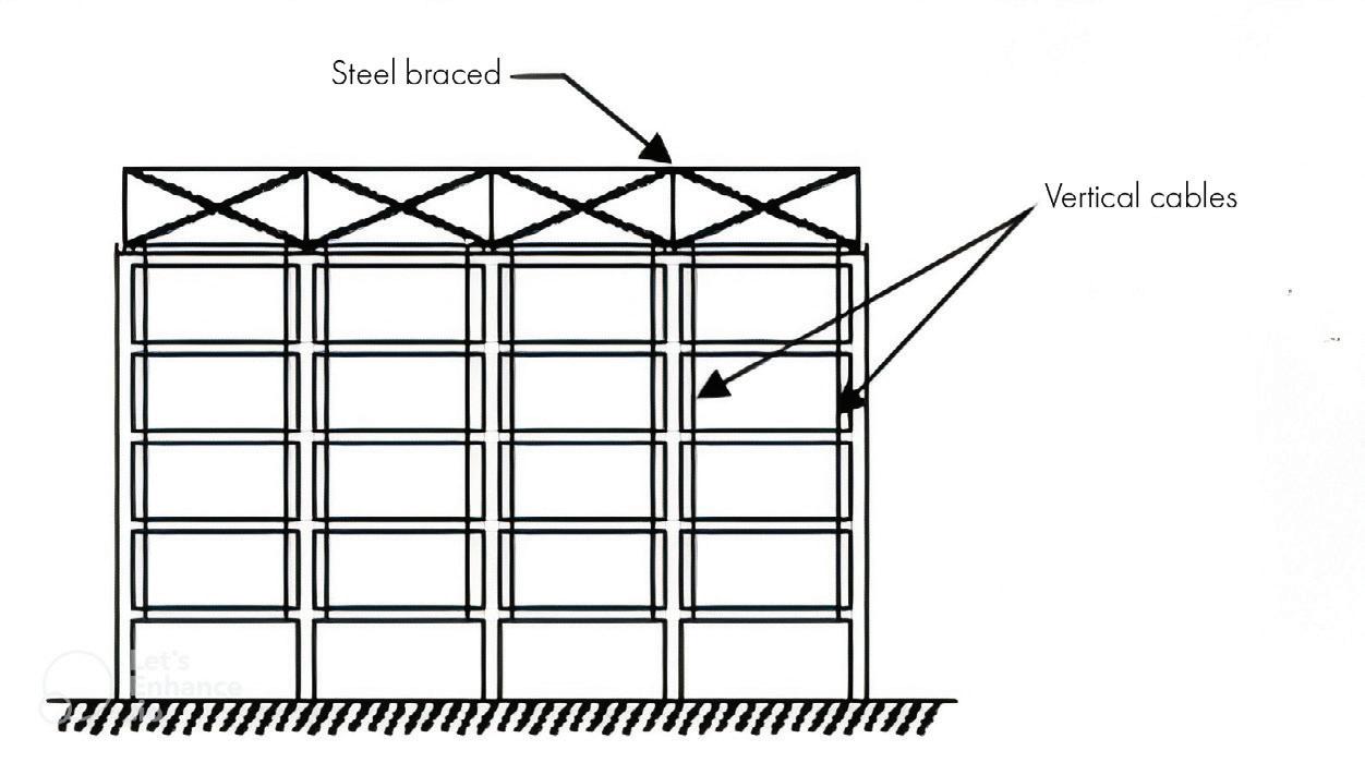
Progressive collapse can be prevented in several ways, one of which is to offer an alternative path over the failed column, vertical cables that run parallel to the columns are hung from a steel hat-braced frame that is positioned on top of the structure. In new buildings, the cables are embedded in the columns; in existing buildings, the cables are connected to the ends of the beams (Fig. 2).
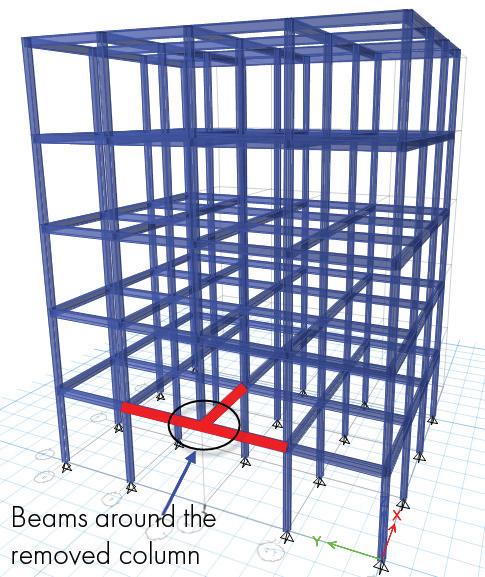
Progressive collapse can also typically be avoided for steel and reinforced concrete structures if the depth of the beams around the
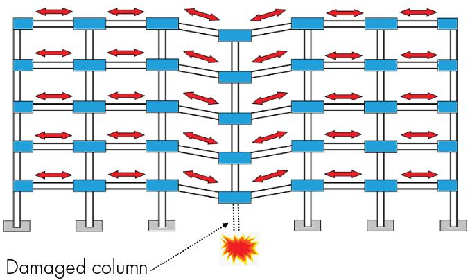
removed column is more than beam span L /15 (for steel structures) and L/12 (for concrete structures) [14,15], [where L is the original span (without column removal)],as shown in Figure 3.
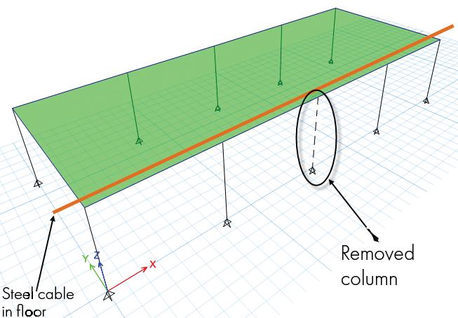
A new way to prevent the progressive collapse of floors, as investigated by Astaneh-Asl, is to place steel cables inside the concrete floor slabs for new construction or add the cables under the slab for existing structures as a measure of retrofit. The main role of these cables is to prevent progressive collapse of the floor in the event of loss of one of the columns.
Figure 4 shows the application of this concept in a building. When a single column is removed and the floor starts to collapse, the steel cable prevents the collapse and transfers the load of the floor to neighboring columns and rest of the structures. Since cables are used in every floor, the loads of all floors above the removed column will be transferred to the adjacent columns. As a result, although the floors might have relatively large vertical deformations on the order of 40 to 60 centimeters (16 to 24 inches), the full progressive collapse and pancaking of the floors are prevented.
Norazman et al. suggested the use of a damage evaluation form in evaluating damaged structures due to various reasons such as an act

• Cutting-Edge Equipment: New 48” technologically advanced glulam press and lay-up system.
• Versatile Production: Widths produced range from 2-7/16” to 10-1/2”, while depths range from 3-1/2” to 35-3/4”.
• Expanded Size Options: Finished Glulam Sizes up to 10 ½” x 35 ¾” x 60’.
• Diverse Applications: Available in various appearance classifications and strength grades for Commercial, Industrial, and Residential applications.
• Superior Quality: Manufactured with superior strength southern yellow pine MSR Lumber.
• Sustainability: Sustainable Forestry Initiative (SFI®) is certified for environmentally conscious projects.



of terrorism. This form is effective and gives a detailed inspection view that could be used as a guide for decision making and planning for rehabilitation work. See the online version of this article for a blank damage evaluation form and how it would be filled out according to the progressive collapse example presented hereafter.
The following is a step-by-step example showing how to perform
progressive collapse analysis of a three-story administrative concrete building exposed to a corner column removal scenario due to explosion (Fig. 5). The evaluation of a blast-damaged concrete building follows the GSA guidelines (see references online).
Gravity Loads were taken as:
• Superimposed Dead Load (Ceiling)= 31.2 psf
• Walls = 907.1 plf acting on beams
• Live Load= 62.4 psf (for administrative building)
• Dimensions of Beams & Columns as follows:
• Exterior Beams 14 × 24 in.
• Interior Beams 14 × 22 in.
• Corner Columns 22 × 22 in.
• Exterior Columns 22 × 22 in.
• Interior Columns 26 × 26 in.
Per GSA guidelines, progressive collapse analysis is completed by removing a singlestory load bearing column on the perimeter of a building per following different scenarios, as shown in Figure 6. For this example, the first-story corner column has been removed (Fig. 7).

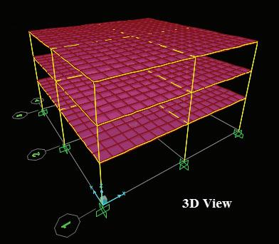
The nonlinear dynamic collapse analysis is needed to observe the formulation of plastic hinges throughout the structure and to determine which elements are failing. Many studies proved that nonlinear dynamic collapse analysis is the best choice to achieve accurate results compared to nonlinear static analysis.
Step 1: Perform traditional design of the concrete building with floor, beams, and columns sized to gravity and lateral loads. Prepare 3D analytical computer model.
Step 2: Define and assign plastic hinges according to ASCE 41 to the beams and columns. Beam hinges to be located along the beam length at the following intervals: each end, midspan, and approximately third points.
Step 3: Define analysis loading. For gravity loads, Dead Load + 0.25 x Live Load is the recommended load combination per GSA. Non-linear dynamic case automatically defined by SAP 2000.
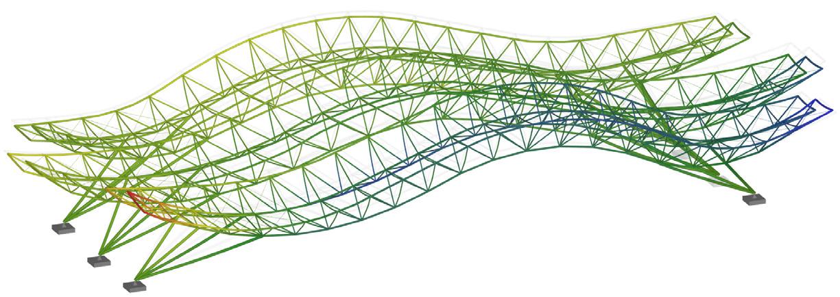
Step 4: Perform progressive collapse analysis (Fig. 8). Note, SAP2000 v21 TRIAL Version can perform dynamic collapse analysis to model progressive collapse.
Step 5: Observe the hinge formation status for all frame members once the select column has been removed.
Step 6: Compare observed hinge formations with damage limits. According to FEMA-356, when plastic hinge rotations for any member exceed 0.025 radians, the member is considered a collapse hazard or in other words, the member has exceeded the collapse prevention (CP) state.
Also, according to Egyptian Specifications for Blast-Resistant buildings, the permissible damage area due to the loss of an external column must be smaller than 753.474 ft2. For the example above, the damaged area of the slab panel above the removed column is 27.8 x 27.88= 777 ft2
The plastic hinges are spread in all beams and columns as shown in Figure 8. The value of most plastic hinge rotations for most members in this scenario exceed 0.025 radians and hence, collapse will occur. Consequently, overall progressive collapse is expected for this structure. ■
Full references are included in the online version of the article at STRUCTUREmag.org .


High-performance structural screws in connections enable high-capacity designs, but they also present challenges like hydrogen embrittlement.
By Dong Han, Ph.D; Lori Koch, MS, PE; Tyler A Davis, Ph.D
As mass timber construction gains momentum as a sustainable and versatile option, designers have sought to create larger structures with longer spans. These designs demand high-capacity structural connections, often relying on case-hardened fasteners manufactured from high-strength steel. Achieving desired strength typically involves increasing their core hardness. Figure 1 shows the key composition of a typical carbon steel fastener for mass timber applications. While increasing core hardness correlates with higher ultimate strength, it also significantly elevates the risk of hydrogen embrittlement (HE)—a well-documented phenomenon in which infiltrated hydrogen reduces ductility, leading to failure under sustained tensile stress. This vulnerability—once an overlooked concern in mass timber, especially in highly seismic regions—now represents a critical challenge for the integrity and durability of today’s increasingly expansive mass timber buildings.

screws intended for wet and dry service conditions, respectively (36 and 38 HRC, respectively, if produced under ASME B18.6.3). These thresholds, derived from extensive empirical data, aim to limit HE risks. As detailed in ISO/TR 20491:2019 Fasteners—Fundamentals of hydrogen embrittlement in steel fasteners, surpassing 390 HV markedly heightens susceptibility to HE, with the effect following a sigmoidal relationship (Figure 2).
In response to industry failures attributed to HE, the Canadian wood design standard, CSA O86, has implemented updates in its 2024 revision on the core hardness of carbon steel fasteners. The new CSA O86 guidelines for fasteners produced under ISO 2702 introduce maximum core hardness limits of 360 and 390 HV for

Crucially, two common misconceptions about HE warrant clarification.
First, ductility determined through bend tests does not guarantee immunity to HE. This bulk property reflects a material’s ability to deform plastically, but typical mechanical testing does not capture
Key
X hardness (HV)
Y normal scatter range - percent notch fracture strength (NFS%)
a Not susceptible.
b Ductile-brittle transition (transition begins as hardness is increased above 390 HV).
c Susceptible [high probability of failure by hydrogen embrittlement (HE)].
d Acceptance threshold for fasteners.
Figure 2. Scatter range of a model HE threshold stress curve for zinc electroplated notched square bars tested in air under four-point bending load (Copied by MTC Solutions with the permission of the Standards Council of Canada (SCC) on behalf of ISO. The standard can be purchased from the national ISO member in your country or the ISO Store. Copyright remains with ISO.)
the prolonged tension required for HE development. Screws that appear ductile during testing can still suffer from HE and fail unexpectedly in service. As such, bend tests are not reliable indicators of HE resistance.
Second, it is important to distinguish between corrosionand HE-induced failures in mass timber screws. While a zinc-plated wood screw may exhibit corrosion resistance and avoid corrosion-related failure, even minor damage to the zinc coating—a common occurrence in steel-to-wood connections— can trigger galvanic corrosion when water is present. This process generates hydrogen at the steel surface, which can readily infiltrate the tensioned screw and result in HE-induced failure, long before corrosion would compromise its structural integrity. Therefore, corrosion resistance must not be interpreted as protection against HE.
The CSA O86 standard emphasizes hardness and HE testing, in accordance with ISO 2702 and 15330, respectively, as some of the most reliable methods to evaluate HE susceptibility. Beyond compliance, mitigating HE risks calls for a collaborative effort among manufacturers, suppliers, engineers, and designers.
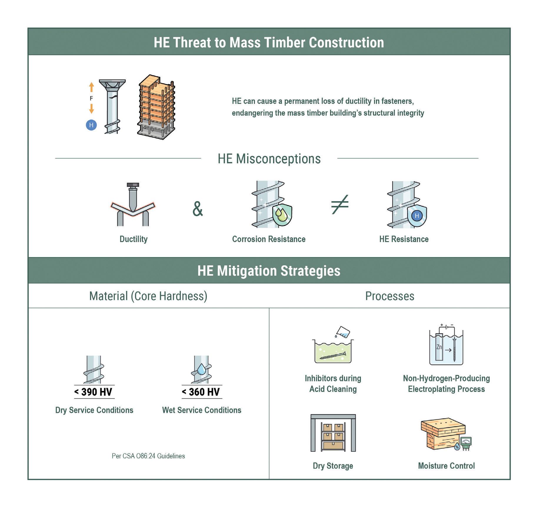
Manufacturers and suppliers play a vital role in minimizing risks associated with internal HE (IHE) during production. They can adopt techniques to limit hydrogen exposure, such as using inhibitors during acid cleaning and implementing electroplating methods designed to minimize hydrogen generation. Proper storage and transportation practices are equally critical to protect screws from moisture exposure. Engineers and designers are responsible for addressing environmental HE (EHE) risks during service. This includes specifying screws with hardness levels appropriate for the intended service conditions (dry or wet). Robust environmental controls, such as measures to reduce moisture ingress, are vital to mitigating the conditions that promote HE. By addressing both IHE and EHE through these strategies, stakeholders can significantly reduce the likelihood of HE-related failures, ensuring the durability and longevity of mass timber buildings.
The evolution of mass timber construction relies on the integration of high-performance structural screws in connections. While these screws enable innovative, high-capacity designs, they also present
challenges like HE. Although HE-related standards for screws have yet to be established in every jurisdiction, designers need to be aware of the potential hazards of HE and the necessary measures to prevent it. Screws should be sourced from reputable suppliers that rigorously test their products and apply best practices to mitigate HE risks before installation.
By understanding HE mechanisms and adopting proactive strategies, the construction industry can confidently advance toward a future where mass timber stands as a reliable and sustainable alternative to traditional materials. ■
Dong Han, PhD, is a Senior Scientific Writer with MTC Solutions. He studied advanced materials for environmental, energy, and biomedical applications and has been involved in scientific publishing for over a decade (support@ mtcsolutions.com).
Lori Koch, MS, PE, is a Senior Product Engineer with MTC Solutions. She is a board member for SEAVa, serves on the NCSEA Continuing Education Committee, and is a licensed Professional Engineer in Virginia (support@ mtcsolutions.com).
Tyler A Davis, PhD, is a member of the R&D team at MTC Solutions. As a peerreviewed author, he has a background in mechanical engineering and material science. His expertise also extends to many complementary fields such as sustainability and building development (support@mtcsolutions.com).
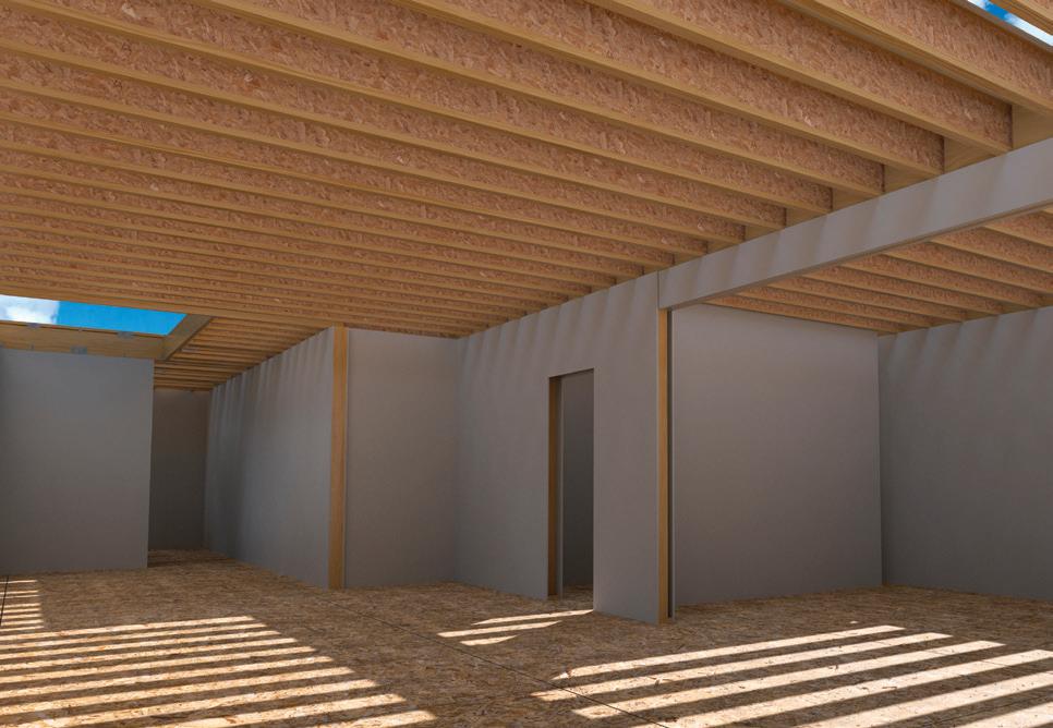
In wood projects, open web floor trusses offer designers, builders, and clients distinct advantages. VS.

The Difference is Design Freedom
With longer spans that require fewer beams, posts, and bearing walls, buyers get open-concept spaces.
See Everything Open Web Can Do mii.com/open-web
Instantly Check Floor Truss Viability mii.com/truss-validator
Need to validate a girder truss or have a truss question? Contact us at designengagement@mii.com.
By Zander Danto, PE, and Paul Cordova, Ph.D, SE
Senate Bills 721 (SB 721) and 326 (SB 326) are two pieces of California legislation related to the inspection and safety of wood framed balconies, decks, elevated walkways, and stairs in residential buildings. Legislators introduced these bills in response to tragic incidents of a balcony collapse in Berkeley, California, and a stairway collapse in Folsom, California, both of which occurred in 2015 and resulted in several fatalities.
In 2018, SB 721 became the first law in California to introduce the inspection of exterior elevated elements (E3s) for multifamily buildings, requiring inspections on a six-year cycle. The bill defines E3s as "balconies, decks, porches, stairways, walkways, and entry structures that extend beyond exterior walls of the building and which have a walking surface that is elevated more than six feet above ground level.” E3s are designed for human occupancy and rely on wood or wood-based products for structural support or stability. An E3 also includes the associated railings and guard-walls.
Inspections must be performed by a qualified individual (e.g. licensed architects, civil or structural engineers, certain building contractors, or certified building inspectors). Inspections must sample at least 15 percent of each E3 type in a property and require "direct visual examination or comparable means," often necessitating exploratory openings where finishes conceal structural elements. These openings are often destructive in nature as they require removing or cutting through the finishes. The purpose of the inspections is to "determine that exterior elevated elements and their associated waterproofing elements are in a generally safe condition, adequate working order, and free from any hazardous condition caused by fungus, deterioration, decay, or improper alteration." Any conditions observed to be of life-safety concern must be reported to the owner immediately and reported to the local code enforcement agency within 15 days of the inspection. The owner is required to provide temporary repairs or shoring to address the life-safety concerns within the same period.
interest development" buildings, the legislature removed this provision before finalizing the bill. SB 326, which focuses on common interest development buildings, was passed in 2019 to close this gap. Although similar in scope and intent with SB 721, SB 326 mandates inspecting sufficient units every nine years to provide 95 percent confidence that the sample's results reflect the condition of the whole. Only licensed civil engineers (added by California Senate Bill 2114), structural engineers, or architects can perform SB 326 inspections. SB 326 leaves the decision of exploratory openings up to the inspector’s judgement, rather than requiring direct visual observation of structural elements. Like SB 721, SB 326 mandates immediate preventive measures if a life-safety issue exists. The inspector must provide the report to the association, and if an E3 poses an immediate safety threat, submit it to local code enforcement within 15 days. There is no timeline for completing the repairs identified in the report for SB 326 inspections.
As both bills require inspecting and commenting on the conditions of the structural and waterproofing systems, the inspector must have sufficient experience in both areas.
Following the inspections, the inspector must submit a stamped and signed report to the owner within 45 days. The report must address the elements' current condition through narrative and photographs, provide repair recommendations and any recommendations for further inspections, and include a statement of the expectations for the future performance of the E3s until the next inspection cycle. Owners must file for a permit within 120 days of the report and complete the repair within 120 days of permit approval for non-emergency repairs.
Although an early SB 721 draft covered condominiums and other "common
SB 326 and SB 721 inspections do not require comparing existing E3s to current building codes. Both bills focus on evaluating the condition of E3s to ensure they are functional, free from damage, deterioration, or decay, and not at risk of partial or complete failure.
These two E3 inspections bills may introduce a level of confusion for California property owners, associations, and inspectors. In response, this article aims to provide recommendations to practitioners by offering insights into the nuances of each bill.
The sample size in SB 326 and SB 721 inspections are critical, as it directly impacts confidence in findings and inspection costs. SB 721 stipulates inspectors should evaluate no less than 15 percent of each type of E3. In contrast, SB 326 introduces a more intricate criterion, necessitating "a random and statistically significant sample of exterior elevated elements for which the association has maintenance or repair responsibility." Balconies, elevated walkways, and stairs are different E3 categories due to their various purposes, forms, and construction. The inspector can break each category into additional types considering varied plan geometries, framing layout, and architectural finishes. When identifying different E3 types on a property, inspectors should determine whether multiple "types" exist within a given E3 category. The inspector must accurately
identify all E3 types on a property to ensure the inspection sample adequately represents the entire population.
SB 326 defines a "statistically significant sample" as "a sufficient number of units inspected to provide 95 percent confidence that the results from the sample are reflective of the whole, with a margin of error of no greater than plus or minus 5 percent." This does not translate to a fixed percentage, as it depends on the total number of each E3 type on the property.
The chart in Figure 1 plots the sample-topopulation ratio required to achieve 95 percent confidence as calculated based on the statistical definition of a confidence interval, which is roughly inversely related to the population size.
At lower population sizes, almost all elements must be inspected to achieve the mandated confidence interval. As the population increases, the sample-to-population ratio slowly decreases but remains above the 15 percent required by SB 721 until the population size exceeds 2,100.

The population size is not always the total number of E3s on a property. When multiple E3 types are present, each type has its population, requiring a sample. In practice, this means dividing all E3s into smaller groups by type, which often necessitates the visual observation of nearly all E3s to comply with SB 326.
SB 326 and SB 721 set forth the minimum number of E3 inspections. However, the inspector should use professional judgment to determine whether conditions on-site warrant inspecting additional units beyond the minimum requirement. For SB 326 inspections that include concealed framing, exploratory openings are not required by the bill, however, the authors recommend selecting a minimum of 15 percent of E3s for exploratory openings to observe the concealed framing.
When selecting E3s to inspect, consider their spatial dispersion across different building elevations, locations within a complex, levels, and corner or end units. The spatial dispersion can result in varying amounts of sunlight, wind, debris accumulation, and water from roofs or overhanging E3s and can result in prolonged moisture exposure where dew, trapped debris, or water infiltration accelerate deterioration. Additionally, plan variations, framing configurations, and architectural features can affect E3 detailing, altering its susceptibility to water intrusion and exposure to the elements. Together, these conditions contribute to different levels of risk for decay and deterioration.
Site plans can only partially reveal the factors influencing E3 exposure before a site visit. The authors recommend selecting spatially dispersed E3s for inspection to account for variations in conditions and when possible, conducting a preliminary site walk before selecting E3s.
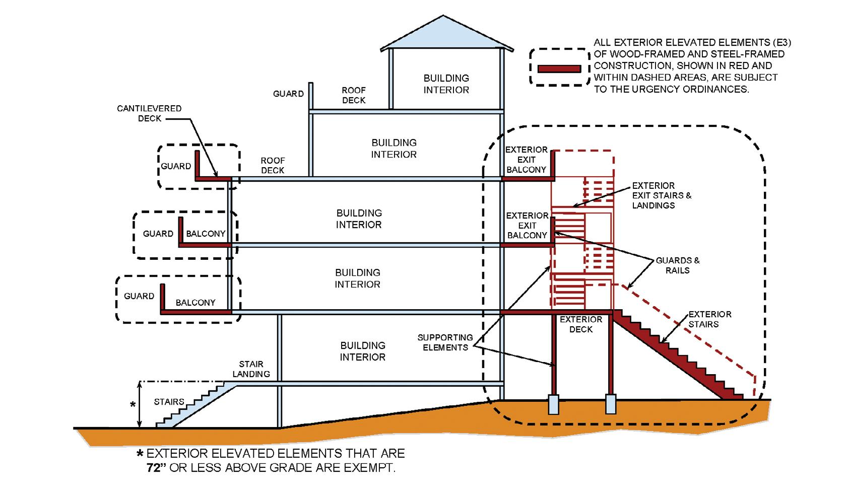
Balconies, exterior stairways and landings, and elevated walkways are the most common E3 structures, but not all buildings contain them. Additionally, some elements within a building may not qualify as E3s due to their layout and construction. For example, a balcony above an
interior space is not classified as an E3 per SB 326 and SB 721. Figure 2 provides examples of elements that meet the E3 criteria.
E3s have various construction types and waterproofing systems. There are two overarching categories: exposed framing and concealed framing. E3s with exposed framing can have a topside waterproofing system or, more commonly, no waterproofing, allowing water to pass freely through the deck (i.e., open deck). In the open deck condition, sheet metal flashing occurs at the exterior building wall to integrate the E3 interface with the building waterproofing. E3s with open deck framing typically comprise wood joists supporting wood or engineered wood decking. E3s with concealed framing vary significantly in construction, with different enclosure materials and waterproofing systems. These variations create numerous possible combinations of enclosure and waterproofing systems, adding complexity to their inspection and assessment.
E3s are commonly framed using either cantilevered joists extending into the building or simply supported joists framing between walls or to exterior posts and beams. Understanding the framing arrangement, whether cantilevered or simply supported, is crucial for identifying potential failure points and the conditions under which failure may occur. Identifying these failure points can help when selecting locations for inspection openings.
E3 inspections take one of two forms. The first is a visual inspection of exposed framing and waterproofing using nondestructive evaluation methods. Inspectors should observe from both the underside and top side of E3s, with particular attention paid to details of susceptible construction prone to water infiltration. These include scupper penetrations, railing attachments through waterproofing membranes (especially top-mounted attachments), exposed upward-facing end grain (such as posts without post caps), and connections that rely on nails in withdrawal from the wood end grain. Visual inspections should note the presence of abnormal staining of the deck or ceiling soffit, soft spots in the deck, loose railings or balusters, corroded bolts and fasteners, evidence of ponding, stucco cracking, biological growth, and improper deck slopes, among other items.
For elements with exposed framing, visual inspection with nondestructive evaluation of the framing and waterproofing is typically sufficient to determine if decay or deterioration are present. For E3s with concealed
framing, visual inspection of exposed finishes and waterproofing can identify locations of potential water infiltration due to distress and discoloration in the finishes, waterproofing, and building enclosure systems. However, visual inspection of finishes does not always correlate with the condition of the concealed framing, so further investigation is necessary.
SB 721 requires direct visual inspection of the framing at a minimum of 15 percent of each E3 type, requiring exploratory openings large enough to assess the concealed framing. SB 326, however, only requires visual inspection of the E3s in the "least intrusive method necessary.” Additional inspections may be necessary at the inspector’s professional discretion if they observe signs of potential deterioration or damage to E3 components.
Regardless of the bill, the authors believe exploratory openings should be made to inspect concealed framing for structural deterioration or decay. Openings should be placed where signs of water infiltration are observed, as well as at select E3s without visible damage. Opening location should also account for likely locations of water infiltration through weak points in the waterproofing, or critical locations where decay could cause structure failure. This approach helps assess the condition of concealed framing, even in E3s that appear undamaged based on visual inspection alone.
When conducting inspections, it is important to develop a consistent notation scheme between all inspectors and review E3 structural or architectural drawings, if available, to identify potentially susceptible details for water infiltration prior to arriving on site.
The properties described by SB 326 and SB 721 are owned and managed by different stakeholders. Each stakeholder requires varying involvement and education on the basics of these two bills from the inspecting party. It is important to have a conversation with stakeholders about the intent of the inspection and what the investigator will be looking for while on site. It is also important to discuss which exterior elements are covered by the relevant bill and which are not but may still pose similar levels of risk.
Both SB 326 and SB 721 require the communication of findings through a report, which includes:
• The current condition of the structural and waterproofing components that comprise the E3s.
• A list of E3s that pose an immediate threat to the safety of occupants and the necessary actions by building management, such as shoring or closure of those elements.
• Recommendations for component repair or replacement that are not an immediate threat to the occupants' safety.
• Expected future performance and projected service life for inspected E3s. SB 721 reports should also include recommendations for further investigation. This may be a recommendation when systemic deterioration or decay have been identified, and further investigation will provide a more complete picture of required repairs.
Inspection reports under SB721 must be submitted to the owner/owner’s agent within 45 days of the inspection. For either bill, if items require immediate attention by the property, the report must also be submitted to the local enforcement agency within 15 days of submitting to the owner.
As both bills require inspecting and commenting on the conditions of the structural and waterproofing systems, the inspector must have sufficient experience in both areas. Otherwise, they should partner with someone qualified to investigate the system that they are not experienced with. These reports serve as the main mechanism for communicating findings to the client and as baseline references for future inspections. It is beneficial to include the inspection scope and a discussion of SB 326 and SB 721 requirements to ensure stakeholders have a comprehensive reference document that can be used for future inspections.
Several areas of SB 721 and SB 326 can be aligned for clarity and simplicity. Alignment of the bills’ inspection frequency, sampling guidelines, and qualified inspectors would simplify the process for all involved.
Additionally, future versions of SB 326 should address explicit repair directives. Whether or not to repair a deficiency that may lead to a life safety concern should not be left up to the owner of the building. Instead, the bills should have a consistent repair timeline across all multifamily buildings.
It would also be helpful to publish supplemental explanations for the bills, such as pictorial representations of what qualifies as an E3. The City of Berkeley's balcony inspection ordinance, which predates SB326 and SB721, has supplemental online directions ensuring that all practitioners properly interpret the ordinance's intent and rules.
Lastly, the various authorities having jurisdiction (AHJs) across the state have varied understanding of these bills, especially their role in enforcement. The state should increase education efforts so that AHJs understand the bill requirements, implications for building owners, and their roles in the process. ■
Zander Danto is an Associate III at WJE in San Francisco, California, and is a member of the SEAONC Existing Building Committee.
Paul Cordova is an Associate Principal at Simpson Gumpertz & Heger in Oakland, California, and is a member of the SEAONC Existing Building Committee.
Several methods are available for providing temporary shoring in existing buildings, with each application requiring careful consideration of several factors to determine the most effective option.
By Ezra B. Arif Edwin, SE; Kevin Conroy, SE, PE, P.Eng; and Brett Holland, Ph.D, PE, SE

Construction in existing buildings can encompass repair, restoration, horizontal and/or vertical expansion, modification of architectural programs, or changes in occupancy classification to achieve project goals. Typically, the project’s Registered Design Professional (RDP) develops construction documents for the final design configuration which only show permanent design conditions and do not consider temporary loading and support conditions. Contractors are responsible for means, methods, and sequences of construction to achieve the final design intent, allowing them to complete the work in accordance with their own preferences and capabilities.
Some projects require temporary structural modifications, while others may rely on the existing structure to support construction activities. Temporary shoring is required when existing structural elements do not possess sufficient strength to support construction loads. Shoring, typically, is viewed as props, posts, beams, or other members installed temporarily to provide support to an existing building element during construction.
The RDP generally does not provide shoring design with the final design documents as it is not part of the permanent structural system. The responsibility for temporary conditions is left to the Contractor, who engages a Specialty Structural Engineer (SSE) to serve as the Design Professional in Responsible Charge of designing and specifying shoring systems. The SSE must consider many factors when designing shoring including, but not limited to, temporary loads during construction, facility use during the work period, appropriate types of shoring, the available strength of the existing structure, including any modifications as part of the work, and the Contractor's sequences, methods, preferences, and capabilities. This article presents several of these considerations and the challenges they can create for the SSE, with examples of how these obstacles were addressed on previous projects where the authors acted as the SSE for shoring design.
Temporary loads during construction and their associated load combinations vary from the loads and combinations used by the RDP to design the permanent structural system. The American Society of Civil Engineering Standard for Design Loads on Structures During Construction (ASCE/SEI 37), defines these loads and generally considers the following three categories:
• Loads associated with the existing building use, including dead loads from existing components and finishes and live loads produced by typical occupancy.
• Loads associated with construction, including the weight of materials, equipment, personnel, and loads applied during construction procedures.
• Environmental loads evaluated based on an exceedance probability during the construction period, which allows reduced environmental loading compared to the values used in design of the permanent structure. ASCE/SEI 37 also recognizes that certain environmental loads may be ignored in combinations where the site would be shut down during an event. Additionally, load factors in ASCE/SEI 37 combinations differ from permanent design load combinations to reflect the range of applications and potential for misuse or errors, as well as the inherent or natural variabilities in loading considered by permanent design load factors. Load factors vary from 0.5 to 2.0 depending on the category of the load (described above), the potential variability in loading, and whether loads are additive or counteractive. The commentary to ASCE/SEI 37 Section 2.2 provides additional information on load combinations to be used during construction.
Construction within occupied spaces requires the existing building to remain functional for occupants and users, which creates restrictions on where shoring and temporary structures can be located and requires design live loads to be considered in part of the structure. Many structures are designed utilizing the full design load leaving little to no reserve member strength. As a result, structures that remain occupied during construction usually require more shoring than if access is restricted to construction activities only, since construction live loads are usually less than the full design live load under occupancy uses, allowing the difference to be used to support the imposed shoring loads.
A project at Chicago’s Union Station Great Hall involved construction of a new skylight and maintenance walkways, over the existing skylight, in the Great Hall Waiting Room. Temporary scaffolds were installed in the building to access high ceiling areas where work occurred. As the location is a major transportation hub, prohibiting public use of this space during construction was infeasible, thus preventing a ground-supported scaffolding system because the supporting posts would have impacted pedestrian flow. To minimize these impacts, scaffolding was suspended from the existing roof structure (Fig. 1). Suspending scaffolding over an occupied floor required significantly more effort by the SSE and contractor to coordinate the scaffold layout and design, existing structure evaluation, scaffold erection, and access methods.
Similarly, a concrete restoration project at a school building in the Midwest required extensive repairs to the mansard roof (French roof) structure during the school year. The unique roof geometry required temporary support by a combination of shoring towers under the roof ridge and spandrel beam along with inclined outriggers at the spandrel beam to resist horizontal thrusts (Fig. 2). This shoring occurred on the second floor, which was closed to occupants allowing a temporary reduction in the live load for that floor. Even considering reduced live loads in restricted-access areas, the second-floor structure did not possess adequate design strength to support shoring, which meant shoring on occupied lower levels was necessary to support the loading. These "re-shores" were concentrated in select locations to minimize impacts on occupied areas. Transfer beams within the second floor restrictedaccess spaces supported the roof shoring towers and distributed loads to the concentrated re-shores in the first floor and basement, allowing continued use of the lower occupied floors.
Shoring temporarily modifies the structure’s load path as construction is completed. Members can see increased or altered loading during the construction period and need to be assessed for these loads. For example, existing dead loads in a single span beam create tensile stresses at the beam bottom flanges; installing shoring at mid-span of a beam creates a continuous two-span condition and additional load creates tensile stresses at the beam top flange that would otherwise be in compression. The SSE must evaluate the existing members and assess whether there is sufficient strength to resist the altered behavior. Many times, existing members lack sufficient strength leading to potential restrictions of variable loads, additional shoring, or differing sequencing. In buildings with high dead load-to-live load ratios that were originally designed using Allowable Stress Design (ASD), utilizing Load and Resistance Factor Design (LRFD) methodology can

sometimes yield favorable results because, where ASD uses a blended safety factor for different load types, LRFD acknowledges that certain loads such as dead loads are known to a greater degree of certainty and can utilize a lower load factor. This more precise approach where load factors are consistent with the probability of exceedance can realize some additional reserve strength.
The existing roof girders supporting the suspended scaffold at the Union Station project initially showed allowable design strengths significantly lower than the required strengths. The SSE analyzed the girders using an LRFD methodology due to the high dead-to-live load ratio to realize additional reserve strength. This analysis also showed the girders were controlled by lateral-torsional buckling due to their infrequent compression flange bracing. Temporary compression flange bracing was added to realize additional design strength. The SSE and contractor also modified the construction sequence to temporarily reduce existing dead loads, prior to installing the suspended scaffold platforms, and limited platform live loads to hand tools and personnel. These steps allowed the work to continue without the need for significant or permanent modifications to the existing structure.
In another area of Union Station where pedestrian access could be restricted, ground-supported scaffolding was utilized. Initial analyses of the supporting floor structure used historical material properties available at the time of construction. Though multiple material strengths may be available depending on the construction timeframe, many industry guidelines recommend conservatively using the lowest available material strength when no additional information is available. The SSE’s initial analyses indicated local overstresses in the floor
structure at some areas; however, a slightly higher material strength would have eliminated the overstresses. A sampling and testing program was developed and material samples from low-stress regions were obtained and tested to determine the actual material strength, which was sufficient to resist the construction loading.
Another technique that can be utilized is temporary unloading which, in this article, refers to the removal of a portion of the existing load on a structural element prior to performing work. The most common reason for temporary unloading is to allow the use of the entire cross section of the repaired member to resist the applied loading. For example, dead loads are typically resisted by unrepaired sections while additional loading is resisted by a combination of the unrepaired and repaired sections. This could result in localized overstress in the unrepaired sections. Temporarily unloading de-stresses the unrepaired sections prior to repairs and, upon removal, allows dead loads to be carried on the full repaired section.
During temporary unloading, the existing structure should be monitored for signs of distress. Visual cues such as (1) excessive or unexpected deformation, (2) cracking, delamination, and spalling in concrete members, or (3) buckling and warping in steel members indicate that temporary unloading operations should be stopped. Auditory signs of distress including popping, cracking, or tearing also can be indicators. If unanticipated distress to existing building elements occurs, further investigation into the existing structural strength may be required, loads may need to be released, or alternate/ additional shoring may be required to avoid additional unacceptable distress. Non-structural building components, e.g., mechanical and plumbing systems and installed finishes, should also be monitored to ensure temporary unloading operations do not unexpectedly affect these elements.
The existing concrete beams at the Midwest elementary school were temporarily unloaded to allow the concrete repairs and additional strengthening to be effective in resisting the structure’s dead load. The beams were unloaded mechanically by incrementally turning screw jacks at the base of the vertical shoring towers supporting the mansard roof ridge. The vertical shoring towers were supported on simply supported steel transfer beams, elevated above the existing second finished floor level. This allowed measurement of the actual deflection of the steel transfer beams to determine the load in the shoring system. The SSE was able to confirm the existing concrete beams were adequately unloaded once the measured steel transfer beam deflections matched the expected deflections.
Construction in existing buildings typically involves limited accessibility within and around the building. The SSE should work with the Contractor to determine how shoring will be brought to the project site, stored, transported through the building to its final location, and erected. The final placement of shoring should also avoid interfering with the Contractor's operations and execution of work.
It is often infeasible for machinery to transport shoring elements through buildings for a variety of reasons. Shoring members are typically transported to their final location and lifted into place manually or using small-scale lifts or jacking equipment brought in through passenger or freight elevators. Shorter length and lower weight shoring

members improve maneuverability and reduce the necessary equipment to lift pieces in place, but may require additional work in the field.
A project at Chicago’s Navy Pier involved dismantling the old Ferris Wheel to install a larger one. The project constructed new cast-inplace reinforced concrete shear walls in the east-west direction, under the north and south feet of the new Ferris Wheel. The new shear walls spanned vertically from existing precast concrete inverted tee beams at the pier parking level (lower level) to a new 12-inch-thick concrete mat above the pier park level (upper level), under the new Ferris Wheel. To construct the new shear walls, the existing precast concrete inverted tee beams at the upper level had to be removed. The upper-level inverted tee beams supported precast concrete double-tee floor beams that required shoring prior to demolition of the inverted tee beams (Fig. 3).
Complicating the shoring design was the fact that the lower level was rated for vehicular loads only (40 psf) which was less than the selfweight of the double tees above (approximately 90 psf). Additional constraints included minimizing contractor operations to place concrete for the new shear walls. Ultimately, a topside shoring approach utilizing steel transfer beams supported on concrete columns at the upper level, with cantilevered beams and hanging supports was developed to support the upper-level precast concrete double tees (Fig. 4). This approach provided unrestricted access to the lower level for construction activities and did not rely on the lower level for support.
When available, original structural and architectural drawings often provide the most direct and reliable information regarding the existing building. Many older buildings are renovated during their life, so site visits should be used to validate information shown on existing drawings and document modifications to the structure since the original construction.
When drawings are not available, literature reviews of historical materials, and non-destructive and destructive testing can be carried out to obtain necessary information about the base structure. Following is a list of references commonly used to obtain additional information about existing structures as well as to evaluate existing structures and design temporary shoring.

• American Society of Civil Engineering/Structural Engineering Institute Standard, Design Loads on Structures During Construction (ASCE/ SEI 37).
• Kidder-Parker Architects and Builders Handbook, Data for Architects, Structural Engineers, Contractors, and Draughtsmen.
• American Institute of Steel Construction Rehabilitation and Retrofit Guide (AISC Design Guide 15).
• American Institute of Steel Construction, Historic Steel Construction Manuals
• Concrete Reinforcing Steel Institute, Vintage Steel Reinforcement in Concrete Structures.
• American Concrete Institute Code Requirements for Assessment, Repair, and Rehabilitation of Existing Concrete Structures and Commentary (ACI 562).
Considering potential construction sequences during design of the permanent structure may minimize the need for temporary shoring. Examples are a design that allows permanent construction to be installed prior to demolition (e.g., at slab or wall openings), designing permanent components to permit un-shored construction (e.g., beam spacing at infill slabs), and detailing optional splices for large or heavy members. In some cases, accounting for potential construction sequences during design can help contractor bids to be more evenly evaluated and can realize cost savings.
While the contractor ultimately remains responsible for shoring design, indicating the need for shoring in the construction documents helps delineate scope and responsibility and allows the contractor to obtain appropriate construction cost estimates. ACI's Code Requirements for Assessment, Repair, and Rehabilitation of Existing Concrete Structures (ACI 562, Section 9.2), recognizes that shoring is an inherent part of repair and rehabilitation and requires that shoring and bracing criteria be shown on the construction documents. The AISC Code of Standard Practice (AISC 303, Section 7.10) requires identification of special erection conditions or considerations required by the design concept that could not otherwise be known by the erector.
The RDP can take different approaches to indicate shoring needs on the construction documents, based on the complexity of the process and potential effects on the permanent construction. Arrows and notes graphically indicating permanent components requiring temporary support allows the RDP to convey scope, while allowing the contractor to design and select shoring materials, systems, and methods to their preferences. Another approach for more complex construction can be to outline a conceptual shoring sequence, as a basis of design for the permanent structure and to provide general guidance to the construction team. In this case, the construction documents should clearly indicate that conceptual shoring shown is for general information only and the contractor is still responsible for the design and specification of the final shoring system.
Construction in existing buildings that modifies or relies on the existing structure for support may require temporary shoring. Many project-specific factors and considerations influence shoring design, which if not considered can increase the difficulty of executing the work. These considerations include:
• Types and magnitudes of temporary loads during construction.
• Construction within occupied spaces and the effect shoring may have on the facility use.
• Construction sequencing.
• Effect of shoring on the existing structure’s load path and individual members behavior.
• Consideration of final repair condition and the effect of locked-in stresses which may require temporary unloading, prior to executing repairs.
• Access and material limitations may limit the use of certain elements.
• Availability of existing structure information.
Working with the contractor to understand their means and methods will result in a successful shoring design and a completed project achieving the project goals. ■
Ezra B. Arif Edwin, SE, is a Consulting Engineer with Simpson Gumpertz & Heger Inc. (Chicago). He received his B. Eng. from the University of Auckland and his M.S. from Virginia Polytechnic Institute and State University. Arif Edwin has over nine years of industry experience in the design of new structures, and the renovation and repair of existing structures. (ebarifedwin@sgh.com)
Kevin Conroy, SE, PE, P.Eng. is an Associate Principal with Simpson Gumpertz & Heger, Inc. (Chicago). He received his B.S. and M.S. from the Illinois Institute of Technology and has over 20 years of industry experience specializing in investigations, evaluations, and the development and implementation of repair designs for deteriorated structures. (kconroy@sgh.com)
R. Brett Holland, Ph.D., PE, SE is an Associate Principal with Simpson Gumpertz & Heger, Inc. (Waltham, MA). He received his B.S., M.S. and Ph.D. in Civil Engineering from the Georgia Institute of Technology. Holland has over 15 years of research and industry experience. He specializes in developing and implementing concrete for high-performance applications, concrete placement troubleshooting, specialized durability requirements, and investigating and repairing structures. (RBHolland@sgh.com)
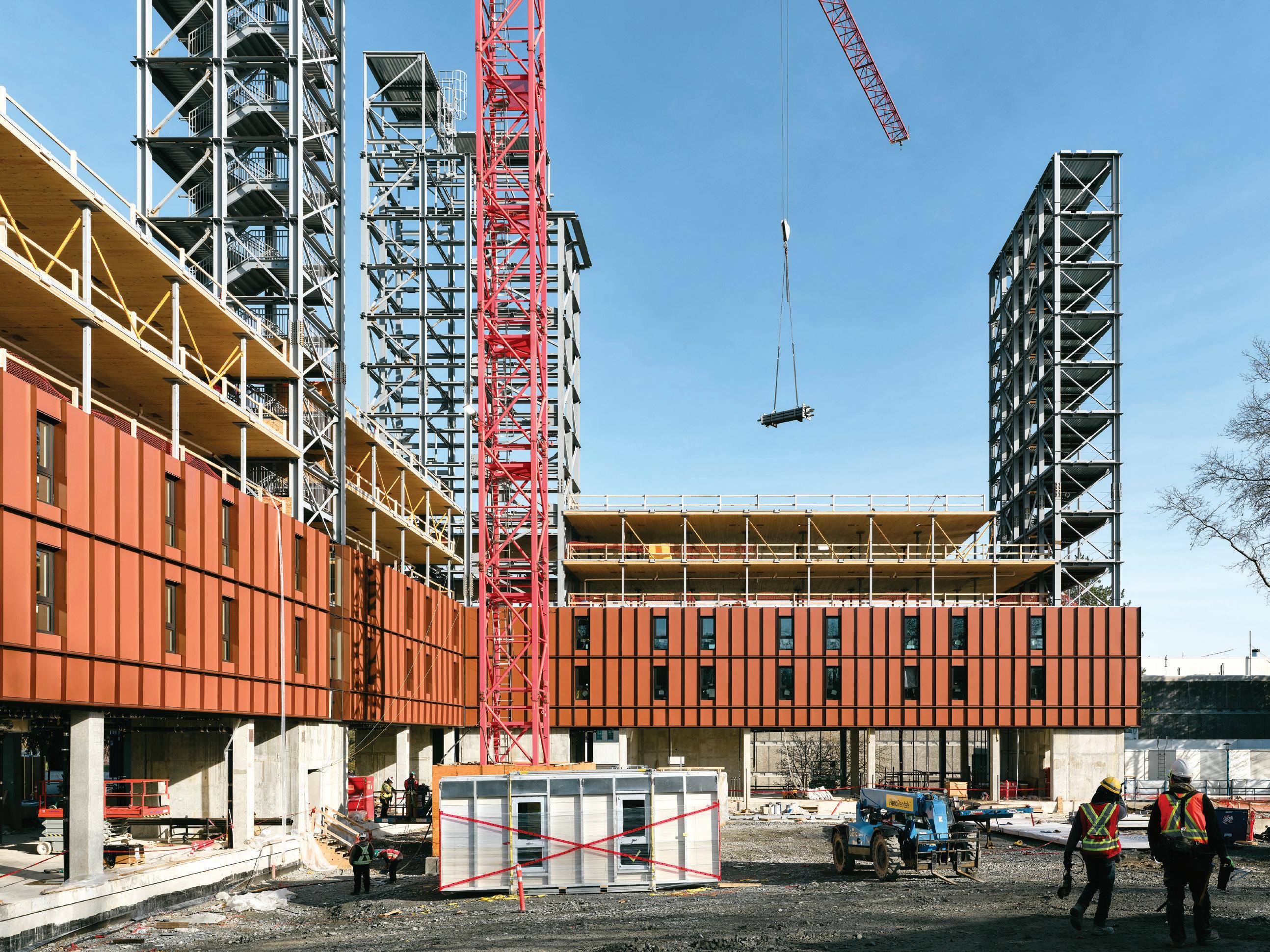
Using the latest advances in engineered wood products, pre-fabrication, and encapsulation strategies, this project represents significant progress in the field of hybrid-mass timber buildings. (Photo
By Jamie Pobre Sullivan, P.Eng, SE
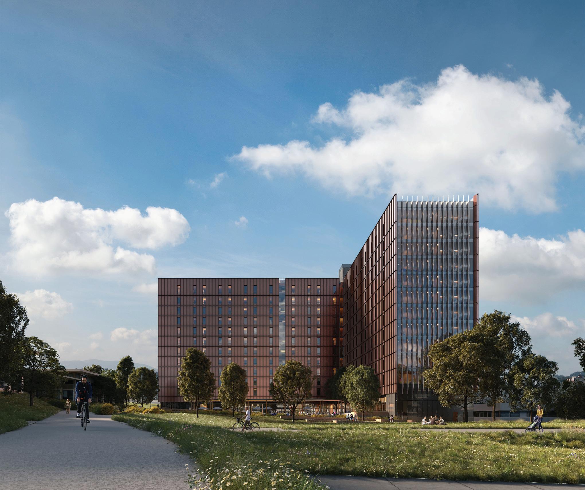
Building tall with mass timber is becoming increasingly more feasible as strides are made to innovate within the tall timber space. The Tall Timber Student Housing project at the British Columbia Institute of Technology (BCIT) in Burnaby, British Columbia, is the first of the next generation of point-supported CLT structures and represents a significant advancement in tall, hybrid, mass timber construction.
This 12-story structure at BCIT builds upon the previous success of the 18-story UBC
Tallwood Building at Brock Commons in Vancouver, British Columbia, that, when completed in 2017, was recognized as the tallest mass timber hybrid building in the world, reaching over 173 feet.
Featuring a single story of concrete at grade, which supports 11 stories comprised of mass timber floors, the BCIT Tall Timber Tower will bring 470 single occupancy studio and singlebedroom units to the campus. Not only does the hybrid structure answer the call for much needed affordable student housing, it also underlines BCIT’s sustainability goals with the use of mass timber and prefabrication.
Each mass timber level features flat, two-way spanning Hem-Fir cross-laminated timber (CLT) floor plates, point-supported on steel columns. The application of 11 feet, 6 inches-wide CLT

panels provided by Kalesnikoff Mass Timber, with a maximum length of 43 feet, 7 inches , incorporates five layers of 2x lumber and utilizes machine stressed lumber in the strong direction to maximize spans, while considering punching shear behavior at column locations.
Punching shear in CLT, like punching shear in concrete slabs, is caused by high concentrated loads, such as at column supports. When high concentrated loads are applied to the face of the CLT panel, laminations are susceptible to "roll" against each other and may cause rolling shear failure. Therefore, considerations were made to detail column-to-column connections with 16-inch square wide top plates on each column at every level to distribute these loads and avoid accumulated loading perpendicular to grain. These direct force transfers are essential to the point-supported CLT system.
The CLT panels are designed to achieve a 2-hour fire resistance rating. This includes one hour of effective encapsulation by way of two layers of 5/8-inch-thick Type X gypsum board layers at the underside, and one hour of char in the wood panel. The 2-inch concrete topping provides full encapsulation to the top side of the CLT panel.
The large-format prefabricated facade panels used on the project, Flynn’s Speedwall system, are comprised of insulated metal panels supported on an aluminum chassis with pre-installed windows. Attachment of these panels to the main structure were designed with consideration to limit deflection in the CLT panels. Gravity connections for the facade panels are located at the column grid lines, where deflection is minimal.

The project incorporates several significant advances in mass timber construction:
• Point-Supported CLT System: The twoway flat slab system without beams allows for unobstructed service distribution and reduced structural depths, enabling tighter floor-to-floor heights.
• Wide format CLT Panels: The 11 feet, 6 inches wide CLT panels align with partition walls, such that columns are concealed within walls and suites are acoustically separated for optimal acoustic performance.
• Testing and Validation: Results from testing, completed at Fast + Epp’s own Concept Lab and in conjunction with the University of Northern British Columbia, validated the point-supported and punching shear reinforcing design approaches for CLT, an approach not currently in the building code. Testing also confirmed the use of Hem-Fir CLT as a point-supported system, a species
historically limited in similar applications due to Hemlock’s tendency to hold moisture in “pockets,” resulting in a required, uneven drying process. Kalesnikoff’s long-standing experience in drying Hem-Fir mitigated risk of this concern.
• Steel Lateral Resisting System: The steel lateral resisting system, designed in selfstabilizing configurations at egress cores, limits the need for temporary shoring during construction. The braced frames were prefabricated in 5- and 6-story lifts to maximize shop welding and allow cores to top out before CLT installation.
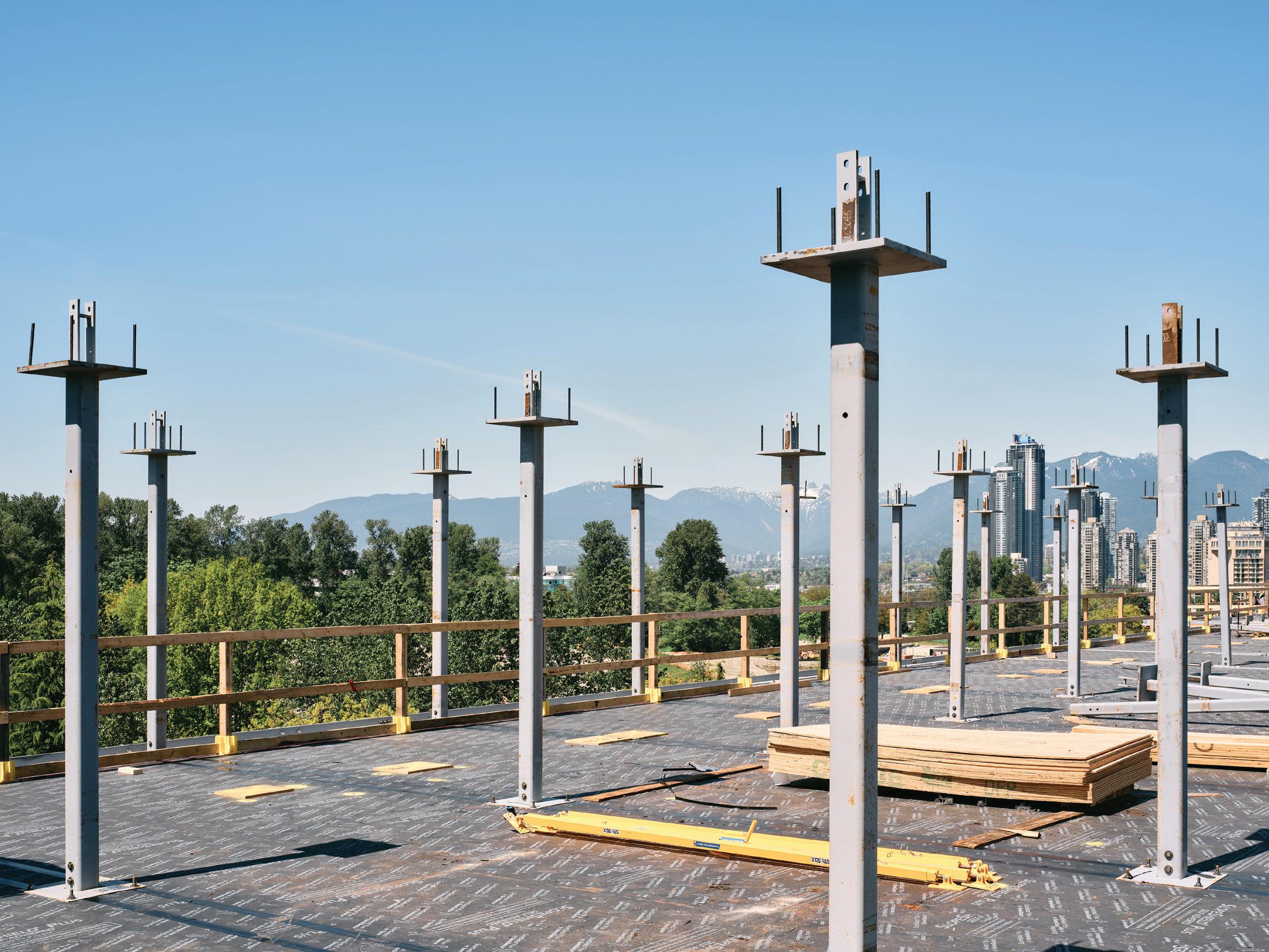
The construction of the BCIT Tall Timber Tower was a collaborative effort involving architects, engineers, and contractors. Early coordination and construction modeling were crucial in accelerating construction timelines, resulting in the building being completed months ahead of schedule if such planning had not been in place.
Construction began late 2022, and the concrete podium was completed by early 2024. Prefabricated components like CLT panels, facades, and steel cores sped up the process, with quick installation of steel braced frames reducing trade overlap. Hem-Fir CLT panels were selected in substitution for Spruce Pine Fir (SPF), keeping product delivery on track despite site delays.
By mid-2024, the mass timber floors were being installed two floors below alongside the prefabricated cladding systems. This method enclosed the tower quickly, reducing weather exposure. The structure topped out late summer and was fully enclosed by early fall 2024, significantly faster than conventional building timelines due to the efficiencies of using mass timber.
The construction schedule was meticulously planned to optimize efficiency:
• CLT Installation Cycle: Starting at Level 3, CLT was installed every 2 weeks. Week 1 involved laying down the floor plate, and
Week 2 focused on installing steel HSS columns for the next floor's support.
• Facade Enclosure: By Week 2 of CLT installation for Level 4, a floor two levels below was already being enclosed with the facade.
• Drywall Encapsulation: From Week 2 of CLT installation for Level 6, a floor four levels below was being encapsulated with drywall. This schedule repeated for each subsequent floor.
• Moisture Mitigation: A moisture mitigation program was implemented by removing water from panels daily, providing drainage solutions and coverage, and monitoring moisture levels. A vapor-permeable membrane allowed panels to dry naturally, and splines were taped immediately after installation.
Prefabrication and an efficient layout reduced crane sharing, contributing to the efficient construction schedule.
Choosing a mass timber structural system from the start helped meet sustainability goals. CLT floors make up 15% of the building's mass, including finishes, and their carbon sequestration lowers the project's overall embodied carbon. Moreover, this project was supplied by a vertically integrated mass timber supplier,
who sustainably manages its own reforestation. The use of a high-performance cladding system further enhances the building's energy efficiency.
This project shows point-supported CLT systems offer a cost-competitive alternative to traditional concrete, particularly for multi-unit residential buildings. The insights gained are shaping future mass timber designs, promoting sustainable and efficient construction practices.
The BCIT Tall Timber Student Housing tower is more than just a building; it’s a symbol of what is possible with innovative engineering and sustainable construction practices. Projects like this play a crucial role in shaping the future of the construction industry as the demand for environmentally friendly building solutions grow. ■
Jamie Pobre Sullivan, P.Eng, SE, is a seasoned structural engineer with over 15 years of experience in structural engineering and design. Her diverse portfolio includes healthcare, educational, custom residential, and commercial buildings, with a specialized expertise in mass timber construction. During her time as an associate at Fast + Epp, Jamie’s work on many projects like this one reflect the high standards of quality and spirit of innovation that push this industry forward.
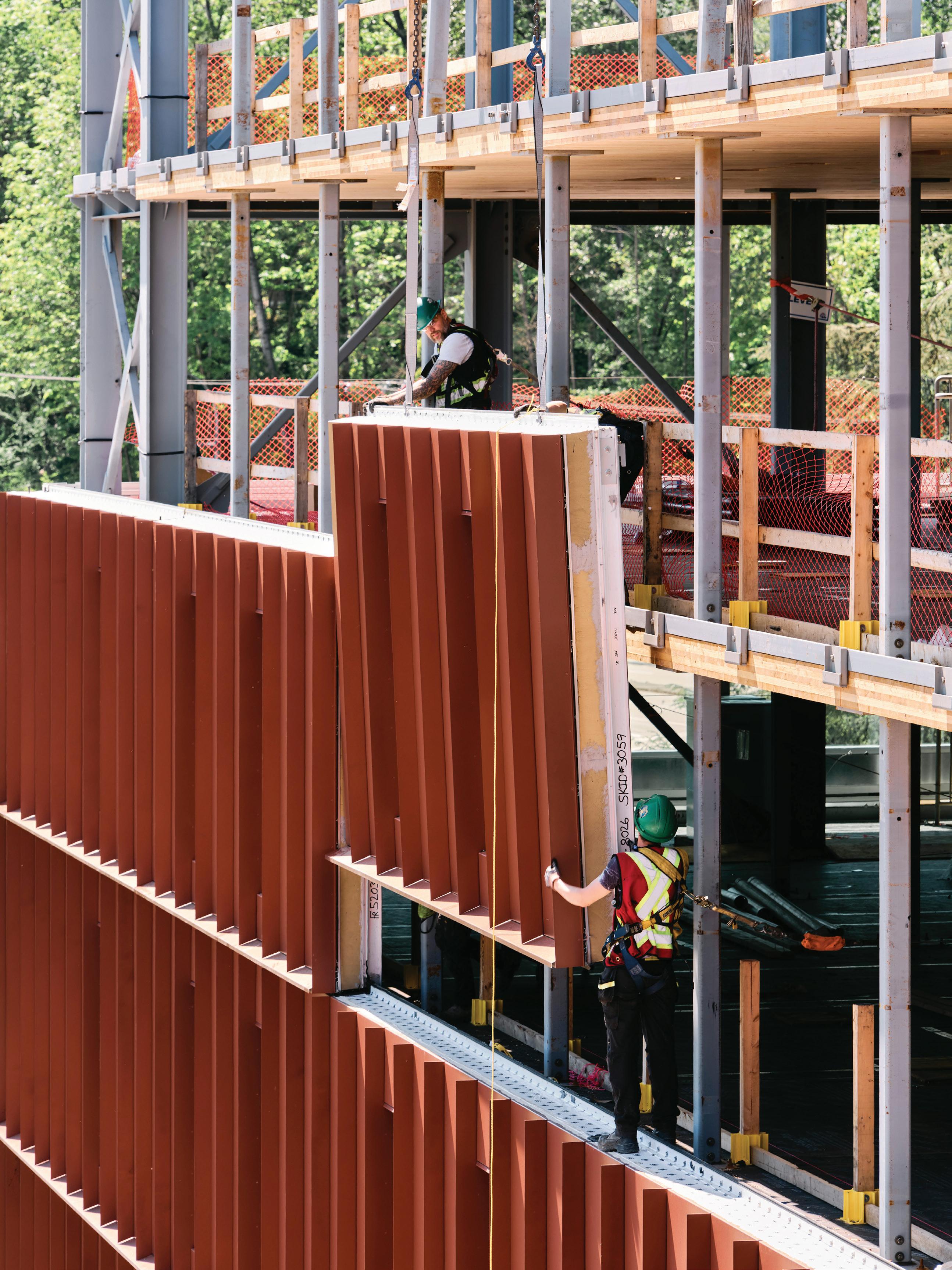

The Fraser Mills Presentation Centre in Greater Vancouver is an exhibition of mass timber engineering.
By Lukas Gispert, B.Eng., Sahar Barzani, M.Arch., Lucas Epp, PE, P.Eng.
As a showcase for innovative mass timber systems, the Presentation Centre at Fraser Mills uses community-focused architectural design and inventive structural engineering to create a welcoming space for the 96-acre residential development. The $10 million Centre is a key destination for those interested in Fraser Mills, encapsulating the essence of the area’s history and future through the use of timber and a swooping, free building form. Built on the former site of one of the area’s largest sawmills, the vision for this building was to pay homage to the rich tradition and craftmanship of the area. The decision to use structural timber was made by developer and owner Beedie Living at the start of the project. Patkau Architects acted as the design and executive architect with StructureCraft as the structural engineer of record and timber design-build subcontractor.
The purpose of the design by Patkau Architects was to weave the past, present, and future together by combining the traditional material—wood—with clean, modern lines and a unique geometry that requires innovative engineering and construction solutions.
The building is shaped like a trapezoid in plan view, but the unique geometry becomes even more evident in elevation as shown in Figure 1. The roof beams vary in slope, getting steeper towards the south portion of the building. The steeper slopes, combined with the wider plan dimension, result in a dramatic roof incline before slowly descending to the roof edge.
The history of Fraser Mills goes back as far as 1890 when the lumber mill was first opened as “Ross McLaren Mill.” In 1906, it was renamed Fraser Mills, and later the neighborhood around the mill was incorporated as a municipality with the same name. In 1971, it was merged with the city of Coquitlam. After 115 years of operation, the mill closed in 2005.
Source: coquitlampubliclibrary.omeka.net.
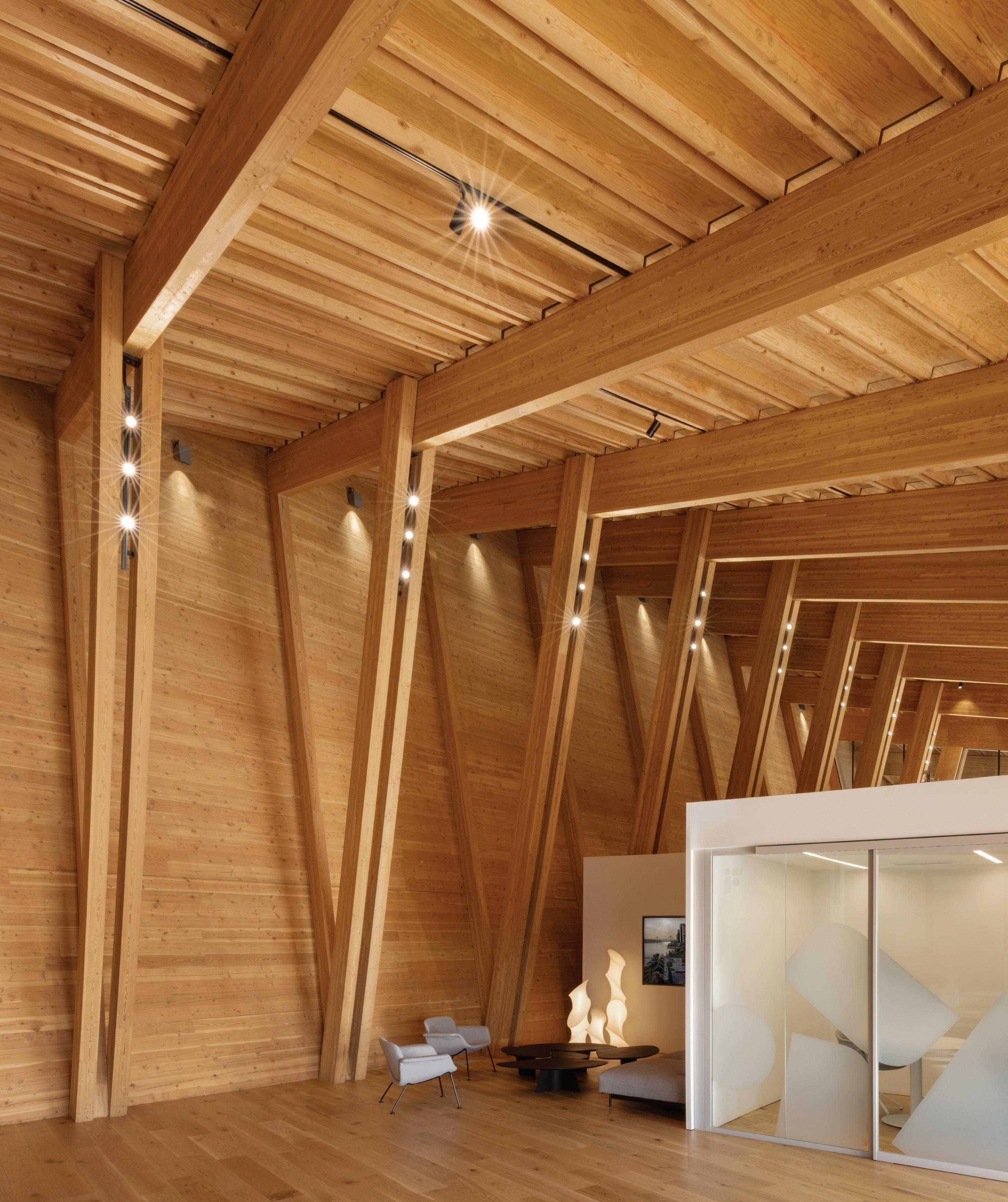


The front of the building features a cantilevered canopy that is 13 feet long and varies in slope along the length of the building, perpendicular to the main roof. When the main roof slope gets steeper, the canopy gets shallower and vice versa. This keeps the relative angle between main roof beams and canopy beams similar throughout the whole building. The cross-laminated timber (CLT) back wall of the building leans outwards and is supported by splayed columns that weave the longer plan dimensions and taller roof elevation together naturally. As shown in Figure 2, numerous options were investigated. In order to avoid obstructions in the interior and to highlight the splayed columns in the back, the scheme on the bottom right without trusses and without webbing in the columns was chosen.
One of the most notable challenges is in the lateral force resisting system, resisting demands of 0.33 g in this high seismic zone. There are no shear walls that run perpendicular to the long direction of the building (i.e. in the plane of the sketches in Figure 2) and the front of the building needed to stay largely unobstructed to maximize the glazing area. The first intuition was to use the series of splayed columns at the back of the building to create a moment frame. However, the splayed columns connect into roof beams with spans so long towards the south that this load path was too flexible to resolve the lateral demand without engaging other building components.

The solution was to use the eight columns at the front of the building as cantilevered columns. Their height was constant throughout the building and their depth could be increased as needed without compromising the glazing area. There was only one caveat: The use of timber
cantilevered columns as the main lateral force resisting system for this load magnitude has little precedence in Canada or elsewhere, especially as part of a mostly pre-assembled building system. This approach therefore required extensive studies and very careful detailing.
With the high seismic demands, StructureCraft had to design the columns for larger overturning moments. While the column itself had enough capacity, there was not enough space at the bottom to place conventional connection hardware.
Instead, the engineer designed a long, threaded rod that connects to the top of the column and anchors it down into the foundation directly, acting as a hold down connection. The asymmetrical shape of the building results in an overturning moment higher in the outward direction than it is in the inward direction, and thus the threaded rod was only required on the inside of the column. The inward moment with the uplift on the outside is resolved with smaller anchor rods glued in the timber. This allowed the column to serve another function: the downspouts of the roof drainage system are integrated into the column buildup. To accommodate the threaded rod, the downspout, and an easy fabrication and assembly process, the column is split in three components: two outer parts with an L-shaped notch at the top to support the transfer beam above and one inner blocking piece to set the distance between the outer pieces.
The cantilevered canopy and main roof beams create a trough in which sliding snow can pile up easily. Especially at the south end of the building, where the main roof gets long and steep, the amount of snow that can slide from the main roof onto the canopy is significant, causing a pile up in the roof valley of up to 6 feet. Therefore, StructureCraft had to design the moment connection of the canopy beams for high demands. The connection also needed to be easily adjustable to allow for the changing beam slopes throughout the building while allowing for easy installation and future disassembly. The solution here was two separate bent plate assemblies, one attached to the end of the main roof beam and another to the canopy beam. At the top, they are connected to the timber with glued in rods to develop the tension capacity for the cantilever moment. These assemblies were preinstalled to each of the beams ahead of time, allowing the main roof beam to land on the transfer beam before the installation of the canopy beam. Linking the two beams were connector plates with through-bolts. To complete the push-pull couple resolving the cantilever moment, four dowels were driven through the transfer beam, allowing the compression from the canopy beam to be passed through the transfer beam to the main roof beam without crushing the wood fibres perpendicular to grain.
At the ends of the building, the transfer beam had to stop at the inside face of the roof beams to protect its end grain. This meant that the typical connection was not applicable here, and StructureCraft designed a unique solution that connected the roof beams and transferred their combined vertical reaction to the top of the transfer beam through bearing. The eccentricity was resolved by screws at the top of the transfer beam, bearing against its end grain at the bottom. The strong advantage of this connection was that the two roof beams could be fully assembled ahead of time, allowing for a simple drop-in installation on site with only four screws to install.
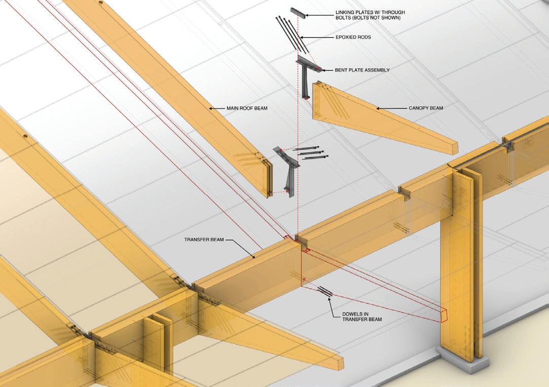
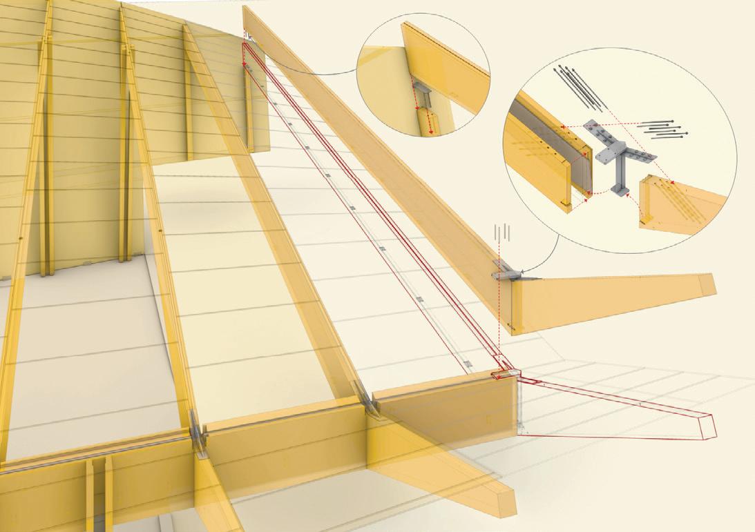
On top of the roof beam, 3x4 Douglas Fir dimensional lumber and ½-inch plywood comprises the roof decking that spans 8 feet between each beam. The challenge here was to find an arrangement of the straight purlins that followed the curved roof without creating a faceted appearance.
To design the curved roof using straight elements, a genetic algorithm solver was employed, optimizing purlin arrangement and enhancing material efficiency. The optimization process focused on three key aspects: minimizing unique types by reducing variations in purlin lengths and cut angles, warp reduction by analyzing curvature and adjusting parameters to flatten highly warped plywood areas, and material efficiency by optimizing plywood panel layouts to minimize waste during the unrolling process. By leveraging this computational approach, StructureCraft rationalized the design to maintain structural integrity and aesthetic intent while streamlining fabrication. This method significantly reduced the number of unique purlin and plywood assemblies, improving constructability and cost-effectiveness.
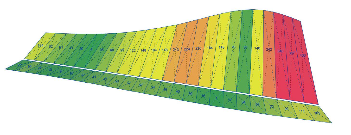
Owner: Beedie Living
Design Architect: Patkau Architects
Structural Engineer: StructureCraft
Contractor: Beedie Construction
Timber Design-Build: StructureCraft
By definition, the presentation centre will only serve its original purpose for a limited time, so it was critical to design the structure and its connections to be easily dismantlable. While the long-term plan is not finalized yet, the developer wanted the option to relocate the structure elsewhere in the development and repurpose it as a community center.
To make that process as smooth as possible, most of the connections use threaded fasteners that can easily be removed. The long rods that anchor the cantilevered columns down to the foundation are equipped with a coupler just above the top of concrete that separates the portion of the rod that is integrated into the column from the portion
that is cast into the concrete. The canopy beam connection can be undone by simply loosening four bolts. A process that is estimated to take less than 10 minutes per beam.
All timber components were CNCed and pre-assembled in StructureCraft’s shop in Abbotsford, BC—close to the project site. This was especially advantageous for the roof beam connection that required high precision and a controlled assembly environment for the epoxied rods as well as the plywood and purlin panels that came in many different geometries. This approach offered the highest quality


finish and sped up the on-site installation time so efficiently that the whole timber superstructure was erected in just 5 weeks.
To guarantee that the exposed connections properly fit together, the glulam frames of roof beams and splayed columns were first assembled flat on the ground, allowing for adjustment and alignment of the members. Once all connections within the frame were completed, the whole assembly was lifted and slowly rotated in its vertical orientation using chain hoists as part of the crane rigging.
This unique project presented many opportunities to push the limits and explore new solutions in the world of timber engineering. The use of buildup column assemblies as the lateral system solved the absence of interior shear walls without compromising the architectural intent of large, unobstructed glazing, and ultimately, the satisfaction of the client.
Careful detailing and prefabrication as well as close collaboration between architect, engineer, and owner allowed all structural connections to be fully exposed while still achieving a pleasant appearance. This is a key consideration for mass timber structures, where covered up or clad structural components are undesirable. Furthermore, most of the connections that were installed on site
are simply bolted or screwed and therefore easily reversable when the presentation centre is no longer needed for this development and is relocated for a second life.
The delivery of the prefabricated structural components and their install was made possible by StructureCraft's unique, vertical integration of structural engineering and timber construction along with state-of-theart computational analysis and design tools. ■
Lukas Gispert, B.Eng. is a Fabrication Engineering Team Lead at StructureCraft where he finds buildable solutions to connections and fabrication details and ensures that all the design intents from the consulting phase are met in practical and cost-efficient ways.
Sahar Barzani, M.Arch. is a Computational Design Team Lead at StructureCraft, where she leads the computational design team on freeform projects, involving such duties as leadership of internal computational teams, schedule maintenance, issue correction and collaboration with the 3D department.
Lucas Epp, PE, P.Eng., is Vice President and Head of Engineering at StructureCraft. He is a structural engineer with more than 19 years of experience working in Canada, the UK, and New Zealand. His expertise with complex geometry and challenging structures has led to involvement in projects where the close interaction of architecture and structure is critical to the success of the project.
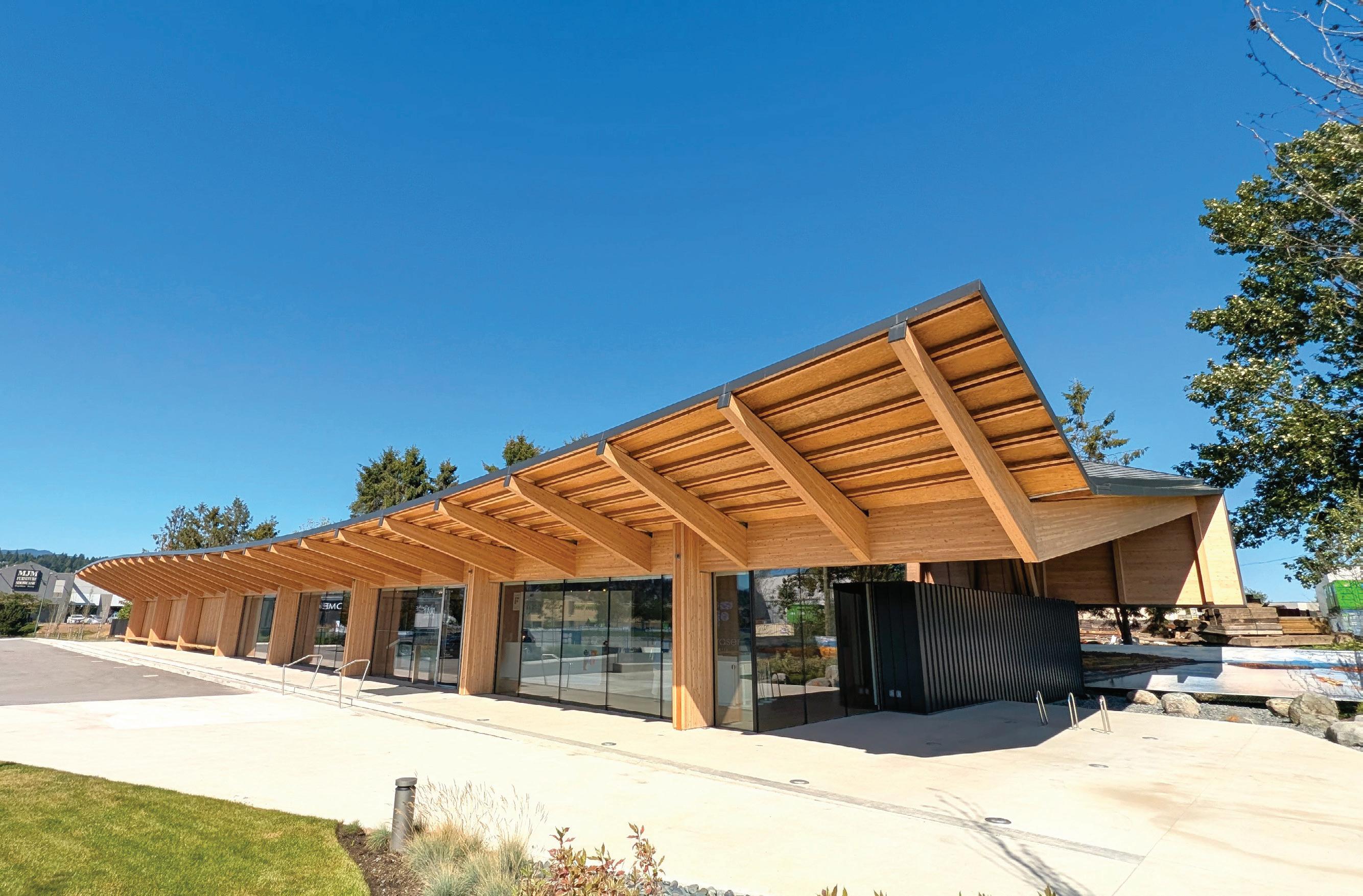

The
is a success story on overcoming engineering challenges and a lifeline for the area’s population.
By Carlos Moscoso
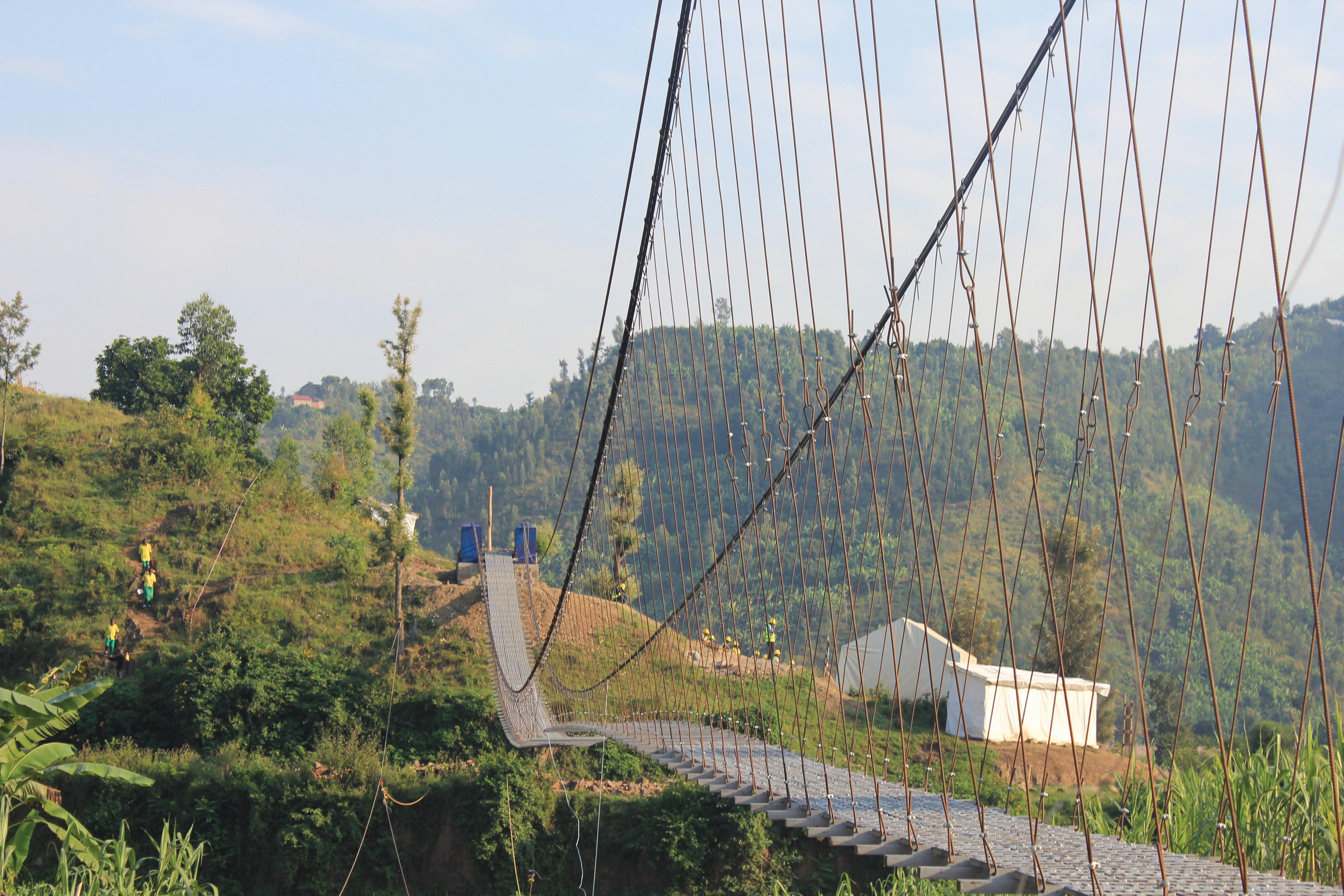
and Lynn Williams

In Rwanda's Western Province, nestled within the steep hills of the Karongi District, a new footbridge stretches across the Muregeya River. This structure is more than a river crossing; it’s a lifeline transforming lives and enhancing community connections. The story of how it came to be is one of genuine collaboration, adaptive mindsets, and resourceful attitudes—and demonstrates how infrastructure can truly make a difference. Constructed in a challenging natural environment under an ambitious schedule, the Muregeya Trail Bridge provides more than 2,500 residents from five communities with safe, year-round access to schools, a hospital, government services, and markets. Built in 2024 by TYLin, Introba, Dar, and Bridges to Prosperity (B2P), it is a record-setting 377-footlong hybrid suspension bridge.
Rwanda’s nickname, the land of a thousand hills, aptly describes the landscape. It’s beautiful but demanding, with the Muregeya River curving and cutting dramatically through the hillsides. During the dry season, the riverbanks stretch 16 feet up from the river. The hills are lush and green, but during monsoon season, this picturesque scene becomes a deadly torrent, with waters rising above the banks.
In addition to its remote location, the new bridge design needed to effectively manage fluctuating water levels and bank instability. The hybrid suspension design features a concrete abutment on one side and a steel tower with a concrete footing on the other. The abutment is securely founded in rock, while the steel tower was constructed far from the river to mitigate the risks of landslides and flooding — issues that washed away a smaller bridge built two decades earlier. As Engineer of Record, B2P designed the bridge and produced the designs and construction drawings. The engineering process followed international design requirements, guaranteeing that the structure could withstand wind loads and pedestrian traffic.
The team constructed the bridge with steel cables, beams, prefabricated panels, and rebar. Due to the limited availability, B2P transported most of the materials from Rwanda’s capital city of Kigali or sourced them from abroad. They recycled the main cables from container ships after U.S.-based ports opted to donate rather than dispose of them. The other materials are durable yet lightweight, allowing the team to divide them into sections and easily assemble them onsite. Before the volunteers arrived, community workers, led by the experienced B2P construction team, hand-carried all materials to the site and constructed the abutment tower. On all B2P projects, the local government pays area workers throughout the construction process. This arrangement provides communities with a temporary wage and the opportunity to gain technical bridge construction, inspection, and maintenance knowledge. It’s a crucial step in ensuring the community takes ownership of the structure and is vital to sustaining the bridge into the future. Following construction, our volunteers selected and trained several community members on inspecting and maintaining the safety of the structure.
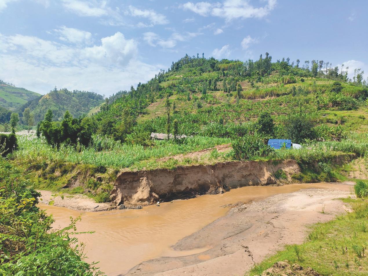
Access to the remote bridge site was challenging. Each day, the volunteers trekked for 30 minutes through mountainous terrain to reach the site. Given the altitude of approximately 9,163 feet and the intense African sun, the hikes were strenuous, even for the fittest.
Once construction began, the TYLin, Dar, and Introba team, along with the local workers, built the tower side of the structure while another construction team worked from the abutment side. With no temporary river crossing, communication between the two teams was conducted solely by radio. The teams used a zipline to send construction materials from one side to the other and did not meet face-to-face until they installed the bridge decking.
With less than 10 days to build the superstructure of the bridge, the construction process followed a series of carefully planned, wellexecuted milestones. The key stages included:
1. Scaffolding and Tower Erection: The first step involved building sturdy scaffolding to help support the hoisting of the 36-foot-high tower. The team installed bumper beams to position the tower. Once the scaffolding was in place, the towers were assembled and painted.
2. Cable Installation: Installing the main cables was critical and challenging. Workers used a zipline and pulley system to pull the cables across the river, spanning the distance between the towers. The team secured the cables to the anchor beams and adjusted the sag value to the proper tension. The sag value is the difference between the position of the cable and the imaginary line between the top of the tower and the abutment structure. The measurement was taken with a level from the other side of the river and required coordination between the two teams.
3. Crossbeams and Suspender Installation: The crossbeams, which provide structural support for the bridge deck, were measured, cut, and assembled. The suspenders, connecting

the crossbeams to the main cables, were installed to create a suspension system that evenly distributes the load.
4. Deck Construction: The bridge deck consists of prefabricated panels, each spanning three cross beams. The teams installed the panels one by one, starting from each side of the bridge and working toward the center.
5. Fencing and Final Details: In the final stage, the team installed fencing and handrails to ensure pedestrian safety. Finishing touches included painting and landscaping around the abutments.
The bridge construction was a collaborative effort between the B2P engineers, the community workers, and the volunteers. When construction roadblocks presented themselves, the B2P engineers provided excellent insight based on their prior similar experience. Ernest Niyigena, the lead B2P engineer responsible for supervising all the local paid workers, was exceptional. The cooperative effort of the entire team was essential to construction success.

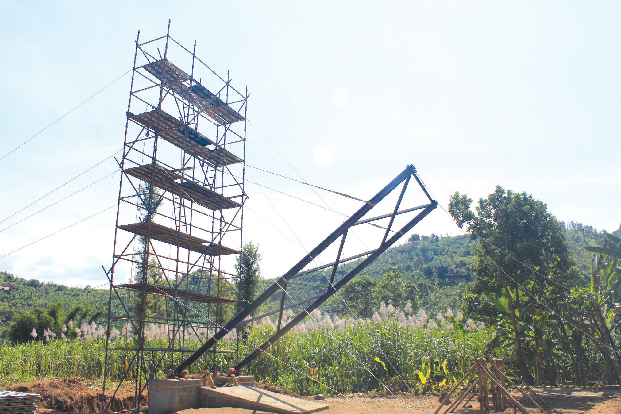
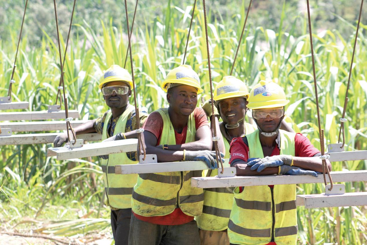
The hybrid suspension bridge design was the project’s most significant innovation, with the decision to extend its length to 377 feet being a close second. Additional instances of resourcefulness during construction included using the zipline and winch to pull the deck cables across the river. This method was safe and efficient, considering each of the four main cables is 1.25 inches in diameter, 558 feet long, and weighs approximately 2,315 pounds. The alternative was to pull them across the river manually. To put that effort into perspective, each cable coil required 10 to 15 community workers to hand-carry it to the site.
The personal challenges on this project were real—from language
At left: The local workers demonstrated outstanding dedication and a strong work
barriers and illnesses to the physical demands of the Rwandan terrain. However, the volunteers became a close-knit group, overcoming each obstacle by supporting one another. The construction team established a successful communication system with three members fluent in Kinyarwanda, the local language, while others improvised with gestures. Among the volunteers, there was no doubt that this experience was about much more than engineering—it was about understanding a community and its people.
Conquering construction-related hurdles was professionally fulfilling, but the warmth and hospitality of the locals was equally significant. They were eager to connect with the volunteers, welcoming them warmly and going out of their way to teach words in their native language and share Rwandan songs and dances. Each day, the community greeted
"I am immensely grateful to the visionaries who brought this bridge to our village. I have seen firsthand the struggles of the school children and the challenges in accessing healthcare and the markets across the river. The fear and uncertainty during the rainy seasons were overwhelming, but now, thanks to this beautiful bridge, those worries are a thing of the past. This bridge has not only saved lives but has also brought hope for a better future for generations to come.”
—Community Bridge Builder

and cheered the team as they trekked to and from the bridge site. In the evenings, children drew pictures and played games with the volunteers. When a brief illness affected the team, the locals provided care and assistance to lift spirits, meet needs, and speed recovery—their efforts were outstanding. Everyone gathered for a celebratory barbecue on the final day before the bridge’s inauguration. The volunteers came away from the experience with a deep appreciation for the Rwandan people’s strength, dedication, and kindness.
The day before the inauguration, the team visited a local school to lead a bridge-building activity. Four students constructed miniature bridges from popsicle sticks and tape and tested the structures' strength during an engaging student assembly. The entire school gathered to witness their peers' inventiveness and engineering skills. The creativity and strength of the structures exceeded the volunteers’ expectations while easily withstanding the weight of marble-laden cups, much to the audience’s delight. To further challenge the designs, rocks gathered from the school grounds were added, but the miniature bridges continued to hold firm, attesting to the students' ingenuity. Afterward, the students performed traditional dances, creating a memorable cultural exchange. The team then joined a physics class, where they shared insights about engineering. This interaction inspired the students and left a lasting impression on the volunteers, highlighting the potential of these young minds to become future builders and engineers.
The successful construction of the Muregeya Trail Bridge was impressive. Still, the personal stories behind the project are what make it unique. The volunteers, many engineers by trade, didn’t just build a bridge—they forged lasting memories with each other and the Rwandan people, creating bonds that will remain in their hearts forever.
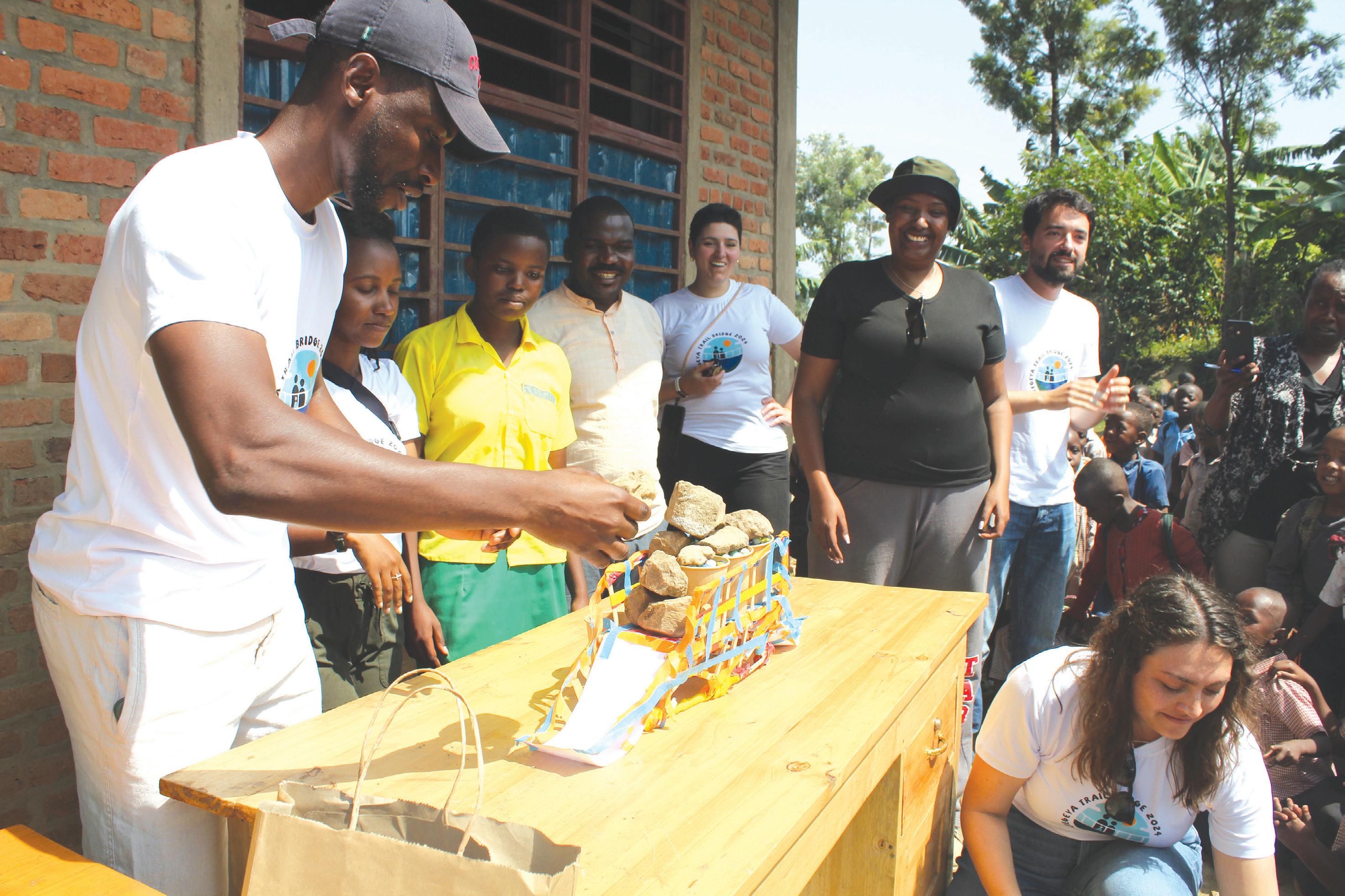
All the volunteers were grateful for the opportunity to influence a community in a long-term and meaningful way and to apply their skills to such a necessary purpose. Reflecting on their experience, many recognized that it changed not only their perspective on engineering but also on humanitarian work and life in general.
The team experienced many strong connections during the arduous construction work. One such moment was when they pulled the thick, heavy cables over the scaffolding and passed them over the tower. The effort was considerable, requiring the strength of many people and precise coordination. The community workers sang to sync their efforts, creating a beautiful moment of unity and teamwork that led to success.
Each volunteer shared a sense of awe at what they accomplished in just nine days of construction. Ghassan Issa of Dar reflected, “I think I underestimated how much of an effect our daily efforts were having until we took down the scaffolding and saw the bridge in its form. That was a moment of direct impact.”
Karim Ali’s most memorable moment was erecting the tower,

“When we started winching the cables and the tower started to go up, I felt like we were doing something huge, and we were an amazing team!”
For Dahria Uwamahoro of TYLin, an engineer accustomed to designing plans, building this bridge by hand alongside the people of Karongi was an enlightening experience. “They all took such great ownership of the bridge building, ensuring that we knew what we were doing and showing us how to do things. It was humbling to think that we were coming to help them, but in the end, they taught us as well. We learned skills we can use in our careers, anywhere.”
Emmy, a local paid worker, commented as she finalized work on the handrail cables, “This bridge was needed.” Her quiet observation was filled with both gratitude and sincerity.
The volunteers arrived in Rwanda as engineering industry professionals. They left with an intense understanding of how infrastructure can transform lives. The completed bridge symbolizes what can be achieved with even the most basic tools through a collective effort and a common goal.
While the Muregeya Trail Bridge is now the longest hybrid suspension bridge ever built by B2P, its impact on the local communities is far more profound. The bridge ensures that 925 children have safe passage to school and 260 women have access to attended births, but it also results in a 30% increase in annual income for the 544 households it serves. What was once a dangerous crossing is now a secure pathway to education, healthcare, and economic opportunity.
Carlos Moscoso del Prado Gredilla is a civil structural engineer and project manager specializing in bridge rehabilitation at TYLin. Inspired by the B2P mission to work with isolated communities to create access to essential services and economic opportunity, he was the Construction Lead on the Muregeya Trail Bridge project.
Lynn Williams, a senior coordinator with TYLin’s Communications + Marketing team, has built a career in the AEC industry writing and editing. Her works include profiling TYLin’s Bridges to Prosperity projects and co-authoring "Niagara Transformed," Civil Engineering Magazine’s March 2020 cover story.
After an SUV damaged the wall of a historic masonry building on a college campus, innovative techniques were used to evaluate the damaged wall conditions and carefully provide temporary support during reconstruction operations.
By Donald Harvey, PE; Namratha Kondam, EIT; Blake Larsen, PE; and Michael Monks

In September 2022, an SUV made an unplanned excursion through a small tree and into the wall of the Guggenheim Building, an unreinforced masonry building on the University of Northern Colorado (UNCO) campus in Greeley, Colorado. The impact occurred near a building corner on a loadbearing wall that supported two floor levels and a long-span roof structure. The masonry wall was displaced by over 4 inches and required reconstruction. However, appropriate selections for the extent of replacement and the methods used for temporary support were critical to avoid further damage or instability in the structure. Innovative techniques were used to evaluate the damaged wall conditions and to carefully provide temporary support to the nearly 2-foot-thick brick masonry wall during reconstruction operations.
The Guggenheim Building was constructed in 1910 and is one of the oldest and most iconic buildings on the UNCO campus. Following renovation in 2007, it became the first building on any university campus to receive the CI Silver sustainability rating
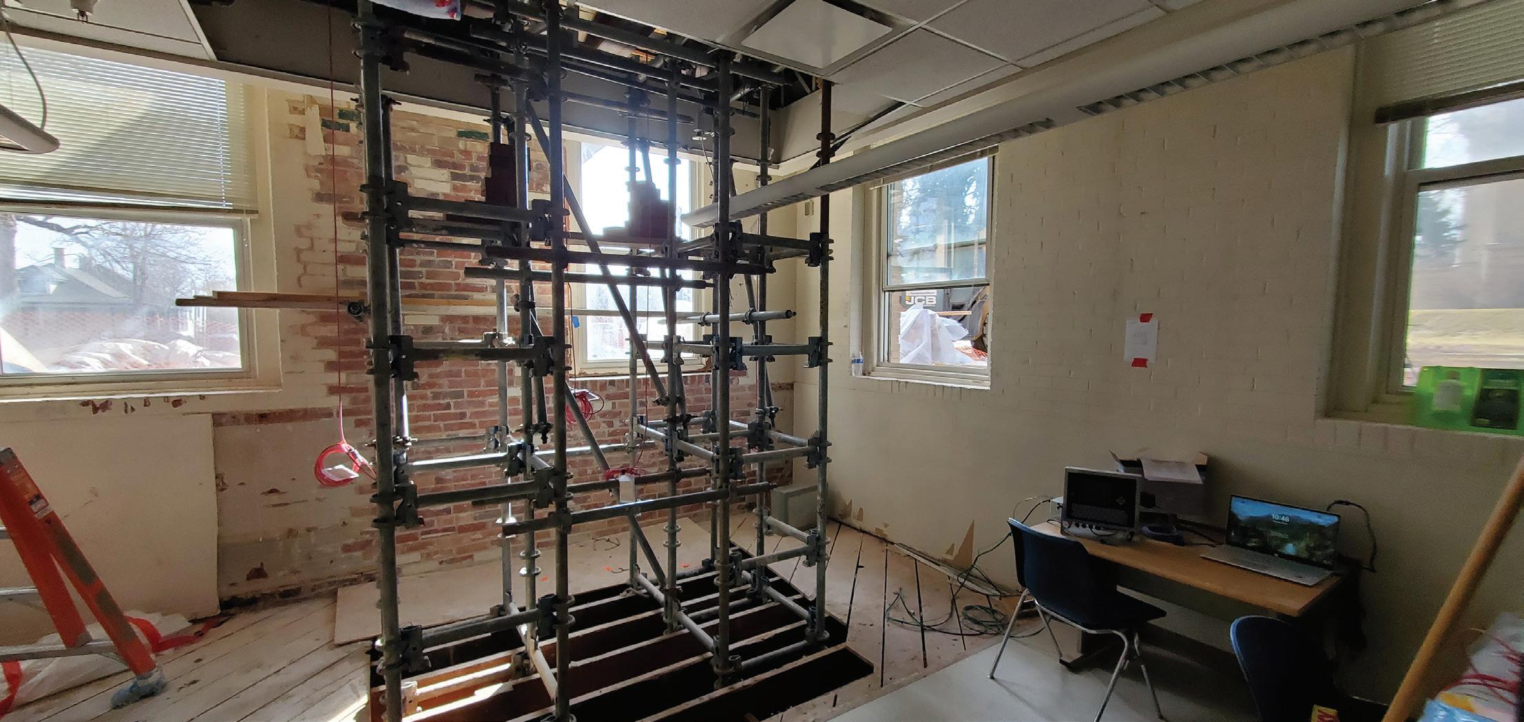
from the Leadership in Energy and Environmental Design (LEED) rating system. It currently houses the School of Art and Design, including office, classroom, and multipurpose spaces.
The vehicular impact resulted in a large area of damage to an unreinforced clay brick bearing wall near the southeast corner of the three-story structure (Fig. 1). The floor and roof framing generally consisted of wood lumber joists and rafters with plank wood decking. Access to this portion of the building was restricted, and within days, steel strongbacks were bolted through the damaged wall area to reinforce the wall. After the temporary stabilization was in place, the investigative engineering team began to identify and quantify the damage. Light Detection and Ranging (LiDAR) scanning (which is a laser-based remote sensing technique to create 3D models) was used to capture the interior surface profile of the damaged wall, and post-processing software was used to evaluate displacements and to define the areas requiring reconstruction.
The scope of engineering work for the masonry repair project included assessment, temporary support consulting, and reconstruction design. The initial phase of the project included site observations, precise measurements, and the use of LiDAR scanning technology to identify areas of displacement and deterioration.
Due to the delicate nature of the damaged area, the structural engineering team worked hand-in-hand with the contractor to design the temporary shoring required for removal and reconstruction of the damaged masonry. This included placement of a temporary foundation for the shoring frames, establishing deflection limits for the temporary supports, and providing preloading parameters to limit movement of the temporary supports.
A repair design was developed in close collaboration with the University, contractor, and design team. The primary goal of the design phase was to restore the masonry wall as closely as practical to its original condition while maintaining the original structural load paths.
Construction proceeded in challenging conditions, including snowy winter weather. Great care was taken to minimize disruption to ongoing classes, with scheduling designed to limit impact on University activities. The repair work also focused on maintaining the historical accuracy of the materials used, ensuring that all repairs matched the original construction. Throughout the construction phase, regular inspections and monitoring were conducted to verify that the work met the design intent and to promptly address any issues that arose.
Temporary shoring at the Guggenheim Building presented several complex challenges, primarily due to the nature and location of the damage and the critical need for careful handling of the sensitive historic masonry structure. Given its unreinforced brick masonry construction and the significant lateral displacement, stabilizing the masonry both temporarily and permanently was paramount to prevent further damage.
The first challenge lay in accurately calculating the loads on the damaged section of the wall. This required analysis of the load paths, considering live and dead loads (roof, floor, and masonry wall), and snow loads. The temporary shoring system had to be designed to support these loads without causing excessive deflection or cracking in the brittle masonry, as even minor deflections could result in further damage.
The need for a shoring system that could handle this brittle nature of the masonry added complexity. The masonry was highly susceptible to cracking, so even slight variations in the load distribution during reconstruction needed to be minimized. Temporary support was carefully planned to ensure that masonry deflections were kept to a minimum. The shoring system also required support both at a temporary exterior foundation and at the building interior, between floor joists spaced 12 inches on-center (Fig. 2). Moreover, there were potential conflicts with the existing ceiling system and fire sprinkler
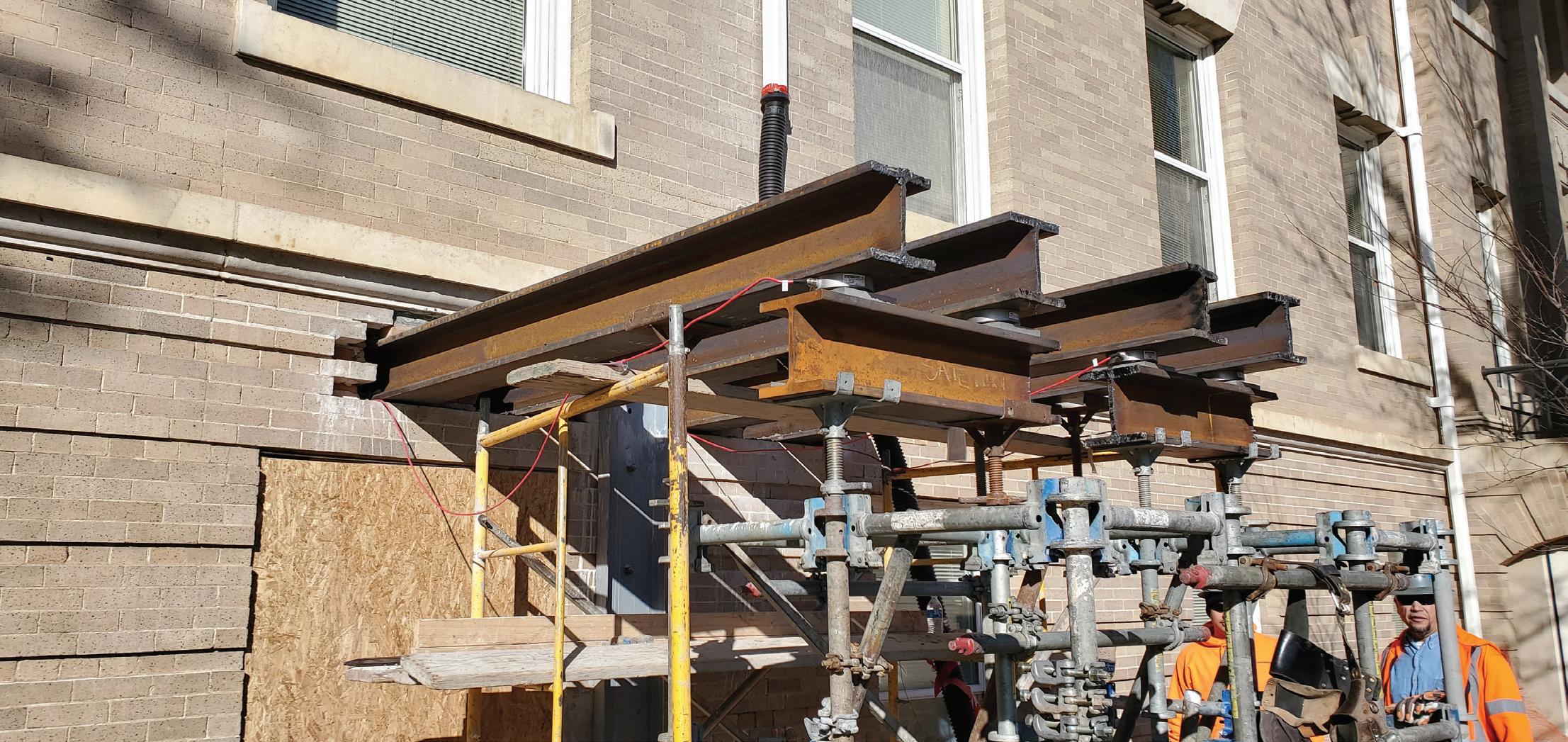
lines at the building interior that added further complexity to the shoring arrangement in terms of where supports could be placed.
The primary method of temporary support involved needle beam
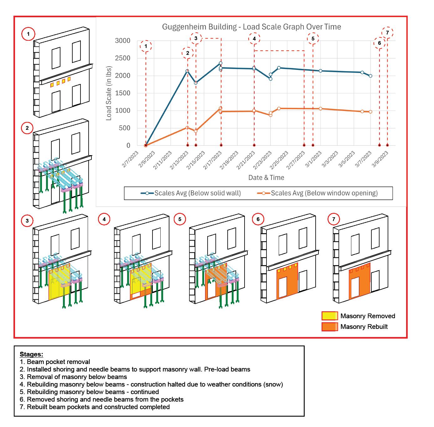
shoring, which utilized four wide flange steel beams placed at 2-feeton-center spacing above the damaged masonry and below the second floor joist bearing. This system was designed by a shoring contractor in collaboration with the design team to manage the vertical loads from the masonry wall, floors, and roof structure above. The beams were supported by shoring towers on both the interior and exterior of the building (Fig. 3). A cast-in-place concrete foundation extending below frost depth supported the exterior towers, while cribbing on the soil floor of the over 100-year-old (and apparently undisturbed) crawl space supported the interior towers. An important detail of the needle beam shoring design was ensuring proper transfer of loads from the masonry wall to the needle beams. To achieve this, dry pack material was used at the bearing surface to distribute the load evenly across the masonry. In addition, the beams were designed with robust sections to prevent rolling and localized buckling. Careful detailing was performed to ensure stability of the shoring frame and needle beam elements. The shoring system included individual screw jacks that were adjusted to fine-tune the leveling of the structure. These adjustments occurred simultaneously on both the interior and exterior shoring supports, with continuous monitoring to ensure the beams remained level and stable throughout the process.
An innovative approach was used at the temporary shoring system to apply a specific preload to needle beams prior to demolition of the supporting masonry below. The objective was to approximately match the estimated actual load that was to be transferred from the damaged masonry to the needle beam shoring when the brick below was removed. Applying this preload by pushing the needle beam up on the supported masonry helped to ensure that minimal sagging occurred once the damaged masonry was removed. However, excessive preload could also lift the
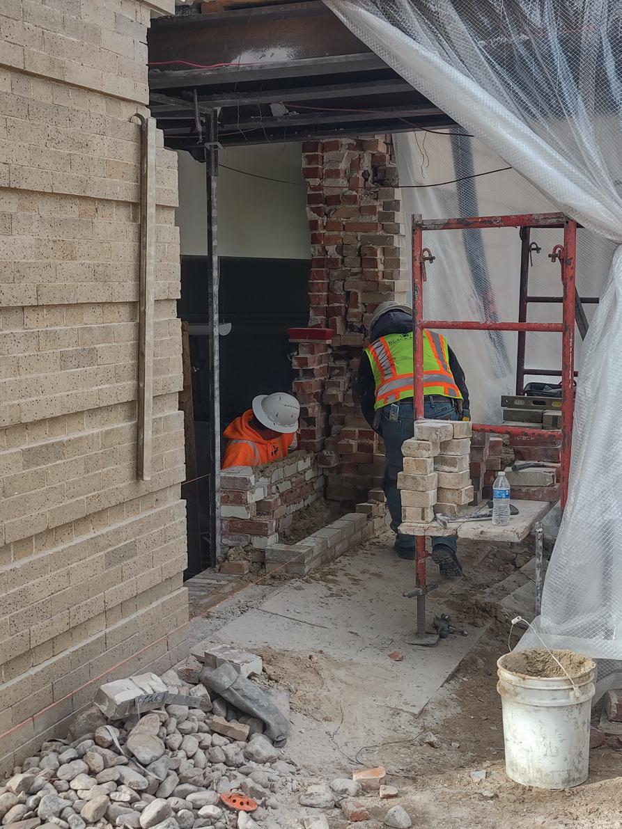

building above and cause cracking and damage to the adjacent masonry.
A novel approach was adopted for preload monitoring utilizing scales originally developed for use in brewery tanks. The preload conditions for the needle beams located below the window opening are significantly different than those at the solid wall area. To monitor these varying preload conditions, one scale was placed at each end of the needle beams, with a total of eight scales used in the system. Four of these scales were positioned on the exterior side of the beams, and four on the interior side. The digital scales were connected to a single monitoring station that provided real-time load tracking. The screw jacks were turned simultaneously at the interior and exterior to apply a preload to match the anticipated load transfer, calculated by the design engineers. This system of scales was left in place and monitored throughout the construction process, allowing for ongoing load evaluation that could provide warning of shifts, sags, or instabilities in the shoring system.
Additionally, a surveyor was tasked with closely monitoring any movements in the structure throughout the demolition, shoring, and reconstruction processes. Survey points above and around the repair area were surveyed regularly to ensure that settlement or other movement was not excessive.
The real-time tracking of both the masonry elements by the surveyor and the needle beam shoring loads with the scale system ensured that the loads remained evenly distributed and that the shoring system remained stable under the various conditions during the demolition and rebuilding phases. A summary of the needle beam loading during the project is provided in Figure 4.
The masonry reconstruction process involved carefully removing damaged masonry using hand tools to prevent damage to surrounding materials and unbroken units that could be used in the reconstruction. The face brick replacement units were sourced to ensure a close match in size, color, and texture with the original masonry. The
reconstruction used compatible mortar materials with careful attention given to the stiffness along with the color and gradation of the sand aggregate to match the original mortar (Fig. 5).
Once the masonry was reconstructed, the final step involved removing the temporary shoring system. This was done after ensuring the masonry had sufficiently cured and the load-bearing capacity of the repaired wall was adequate to support the structure. The holes created by the needle beams were filled with brick masonry, restoring the wall to its original condition.
The temporary shoring and masonry reconstruction at the Guggenheim Building was a successful, carefully coordinated effort. A collaborative design process and meticulous monitoring ensured that the needle beams and shoring system effectively supported the structure while the damaged masonry was removed and rebuilt. The installation and preloading of the shoring, along with ongoing movement monitoring, were closely tracked to maintain safety and stability throughout the process. As a result, the repairs were completed seamlessly, and the final outcome is virtually invisible (Fig. 6), restoring the building to its original condition without any visible signs of the extensive work that was done. ■
By John Dal Pino
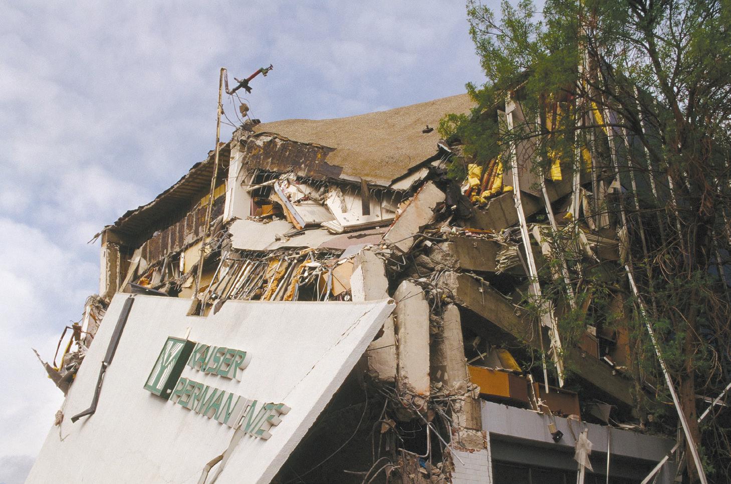
Past earthquakes in California have shown that some concrete buildings, with certain design and detailing characteristics, perform poorly in large earthquakes and have long been known to present threats to life-safety. This undesirable performance is mostly attributable to shearcontrolled strength of certain structural elements: pure frame structures lacking joint reinforcement and sufficient column ties (Fig. 1) and captive short columns or the influence of non-structural components on the structural system (Fig. 2).
As a result, the cities of Los Angeles, Santa Monica, and West Hollywood enacted mandatory retrofit ordinances for all concrete structures (except detached single family homes and duplexes) built with an application or using a building code edition enacted before January 1977. To quote the Los Angeles Ordinance (with dates added for historical purposes), the justification for the ordinance is:
In the Northridge Earthquake (1994), many concrete buildings constructed prior to the 1976 Los Angeles City Building Code provisions performed poorly and collapsed, causing loss of human life, personal injury and property damage. Similar loss of life, injury and property damage occurred in the Great Hanshin Earthquake (1995, often called the Kobe Earthquake), Mexico City Earthquake (2017 or possibly 1985), and Christchurch New Zealand Earthquake (2011) due to the outdated building codes in those communities.
Like most of the other retrofit ordinances discussed in this series of articles, the first phase involves an evaluation of the structure followed by a longer time frame for retrofit or demolition as the second phase. In the case of Los Angeles, the first phase is three years long and starts when the building department first notifies the building owner that their building is subject to the ordinance. This is called “the order.” The second phase is 25 years long dating from the order.
Buildings are subject to retrofit unless the seismic evaluation can demonstrate that:
1. The strength of the lateral-force resisting system meets or exceeds 75% of the base shear specified in the current seismic provisions of the Los Angeles Building Code (LABC) (basically ASCE 7 or the 475-year return period earthquake). Elements not part of the lateralforce resisting system shall be adequate for gravity load effects and seismic displacement due to the full (100%) of the design story drift specified in the current LABC. This is generally considered to be a collapse prevention performance goal.
2. Meet or exceed the requirements specified for “Basic Safety Objectives” (BSO) using ground motions and procedures established by the LA Building Department based on ASCE 41. For those not familiar with ASCE 41, the BSO has two thresholds, one for life-safety and the other for collapse prevention.
The breadth of this ordinance is very broad and rivals that of the retrofit ordinances for URM buildings and concrete tilt-ups during which past California earthquakes have shown as unacceptable hazards. It is unusual, however, to use the earthquake performance of concrete buildings constructed in other countries designed using non-U.S. building codes and constructed using non-U.S. practices to justify our retrofit ordinances.
San Francisco is currently considering enacting a concrete building retrofit ordinance. In mid-April 2024, after many years of debate, the city published a document titled Stakeholder Engagement for the Concrete Building Safety Program (CBSP) which discusses concrete building safety, various stakeholder perspectives and how a seismic retrofit program would be enacted, starting with developing an accurate inventory and completing a screening checklist prepared by the owner’s structural engineer. The CBSP if enacted in an ordinance will address concrete tiltups (discussed in Part 3 of this series and long overdue for San Francisco) and older concrete buildings.
Concrete buildings are not all the same when it comes to seismic performance. History has shown that “pure” frame buildings with widely spaced ties in the columns or those with deep spandrel beams and short captive columns are the worst performers. The most contentious as to whether they should be included or not were apparently the many mid-rise apartment buildings (Fig. 3) dating from the 1920s through 1940s with complete gravity frames (structural steel or concrete), wood or concrete floor diaphragms and “solid” non-bearing perimeter concrete walls (usually 6-inch thick over the full height with light reinforcing) pierced for windows. In some buildings, the perimeter steel frames are also detailed with “wind frame brackets” in the beam-column joints. Many engineers would argue that this second group of concrete buildings haven’t been shown in past earthquakes to perform unacceptably as a class of structure and therefore don’t warrant evaluation or inclusion in a retrofit ordinance. Post-elastic analysis, involving considerable engineering effort, is obviously required to truly understand how these structures will actually perform in major earthquakes mainly because US buildings of this class haven’t been tested in a really large earthquake.

Analysis of the shear walls in this class of structure usually shows that the wall piers are shear-controlled (very lightly reinforced) and lack sufficient shear strength using common acceptance criteria. But not all of these buildings are the same. Most engineers would argue that the ones with steel gravity frames are superior to concrete ones, concrete diaphragms are superior to wood diaphragms even though heavier, and the presence of embedded wind-frames is a superior feature since they create a secondary line of seismic resistance and contribute to structural stability should the concrete shear walls be overloaded. The CBSP lists a number of characteristics which exempts a building from the program, with buildings having steel gravity frames as one.
The 1994 Northridge earthquake was the first earthquake where a significant number of welded steel moment frame connections, with fully welded flanges and bolted webs, sustained considerable damage, mostly cracking in the beam flanges that sometimes propagated into the column. Metallurgists and fracture mechanics experts opined that these types of connections would almost inevitably failure due to the three-dimensional nature and stress flow in a WF beam to WF column arrangement. In any event, most of the profession was caught entirely off guard.
In a nutshell:
1. It was common practice to leave the backing bars for the complete penetration welding of the beam flanges in place after the welding was complete. This created a discontinuity or “crack starter” at the root of the weld that could produce a crack when the beam was bent under high load.
2. It was more common for cracking to occur in the bottom flange of the beam because the “crack starter” was at the extreme fiber subject to the greatest tension stress. This is not the case at the top beam flange since the flange welds were usually made in the downhand position. The crack starter is in a lower stressed location. In buildings with concrete fill on metal deck floors, the floor slabs resisted some of the bending in the beam-column joint due to composite action, which also reduced the demand on the top beam flange.
3. The original research and testing of the welded connections employed smaller beam sections that happen for various reasons to perform better. The research was assumed to apply to larger beam and column sections when the prescriptive building code provisions were drafted. To the extreme dismay of some engineers, the continued use of traditional bolted-flange moment frame connections had to be justified.
4. Steel frame system design was economized, from moment connections at all beam-column joints, to moment connections only on the perimeter of the building (Northern California engineers fairly or
unfairly called these “LA frames”) and finally to only certain bays on the perimeter, sometimes only one bay on each side.
After the earthquake, the profession, university researchers and the steel industry conducted extensive investigative research that resulted in new code provisions, new types of moment connections and methods for retrofitting.
But the question remained, since to date none of these buildings has collapsed in an earthquake, as to whether retrofitting pre-Northridge steel moment frame structures is necessary. The retrofits are not particularly difficult (removing the back-up bar, back-gouging the weld, and adding a protective cover fillet weld) but the disruption to building tenants and the cost is high. So the answer is “it depends.”
The factors that need to be considered are:
1. What criteria will be used to evaluate existing structures?
2. What type of analysis can be used to exempt an existing structure?
3. What part can or should redundancy play? How many connections are there in the building and how many can crack in some form without compromising the entire structure?
4. How do we deal with the myriad number of member sizes in terms of predicting performance – smaller beams and columns, larger, deeper beams and columns, a mix of both?
5. Since weld fractures are brittle by nature, and therefore random, how do we predict which ones will fracture?
6. Should the column splices be evaluated too? Column splices often relied on partial penetrations welds. What are the implications of a column splice failure?
As you can see, any ordinance short of mandating that all welded connections be retrofitted is going to be complicated. It is no wonder that pre-Northridge steel moment frame structures have been left to last in line. ■
This is the final installment of a four-part series. Earlier installments were published in the February, March, and April issues of STRUCTURE.

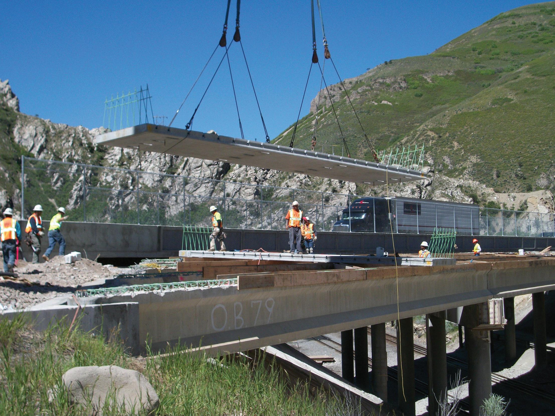
The rehabilitation, repair, or complete replacement of bridges is often a costly and time-intensive process. SLC made with lightweight aggregates such as expanded shales, clays, and slates reduces the weight of precast elements without compromising strength or durability.
By Michael Robinson
Data contained in the National Bridge Inventory (NBI), which is collected by the Federal Highway Administration (FHWA), reveals that just over 42,000 bridges, or nearly 7% of the total inventory of bridges in the U.S., as reported in 2024, are rated as being in “poor” condition. This rating may indicate that these bridges are candidates for repair or replacement.
Concerns about this relatively large number of bridges in “poor” condition are valid and have persisted for a number of years. To address this concern, the Infrastructure Investment and Jobs Act (IIJA) was passed in 2021, which allocated $27.5 billion through a formula bridge program, with $15.9 billion already distributed to many states in the first three years, as reported by a 2024 report
by the American Road & Transportation Builders Association (ARTBA). Furthermore, states have committed 46 percent of these funds, which is about $7.3 billion, to over 4,170 bridge projects.
The sheer volume and complexity of needed repair or replacement of bridges mean that the currently available resources, though significant, are not enough to address the problem if only conventional approaches are used. This situation calls for innovative cost- and time-efficient solutions offering long-term performance improvements. To meet the needs of the moment, some engineers have turned to precast concrete components, such as pretensioned and post-tensioned girders, slabs, and piles, as well as substructure elements, such as pier caps and columns, to accelerate bridge construction and to enhance the durability of concrete elements.
Factory-made precast concrete elements ensure precision and quality while enabling concurrent construction processes, which can significantly reduce project timelines in many cases. However, one challenge with using precast concrete bridge elements on existing structures is they are typically made using normal weight concrete, which is very heavy and places additional loading demands on existing bridges. Plus, the use of precast concrete elements may increase transportation costs and logistical complications, risking delays, damage and budget overruns.
Structural lightweight concrete (SLC) made with lightweight aggregates offers an excellent solution by substantially reducing the weight of the deck when used in cast-in and precast concrete components through its lightweight properties. The reduced weight improves design efficiency and may contribute to accelerating project delivery—all without compromising strength, durability, or long-term performance.
SLC has been used in the building construction industry for nearly a century. The reduced density of concrete mixtures offers structural engineers significant opportunities to lower the load on their projects, especially in bridge applications. SLC mixtures that contain manufactured lightweight aggregates like expanded shales, clay, or slate (ESCS) typically have a density from 110 to 125 pounds per cubic foot (pcf). Taking it a step further, SLC mixtures can be designed to achieve a density as low as 90 pcf, which is nearly a 40 percent reduction in weight from typical normal weight concrete with a density between 140 pcf to 155 pcf.
The material properties of ESCS lightweight aggregates play a crucial role in the performance of SLC mixtures. This type of lightweight aggregate is produced by heating the raw materials (shale, clay or slate) in a rotary kiln to temperatures from 1900 to 2200 degrees Fahrenheit. This manufacturing process produces a high-quality, uniform, structural-grade lightweight aggregate with well-distributed, unconnected pores of moderate size (5 to 300 μm) surrounded by a strong, relatively crack-free vitreous ceramic matrix.
The internal composition of lightweight aggregates and the resultant reduced density of SLC mixtures offer significant benefits to bridge components, whether cast-in-place or precast.
As span length increases, dead load can become a more dominant component of bridge design loads. For engineers dealing with existing structural systems in bridge repair and rehabilitation projects,
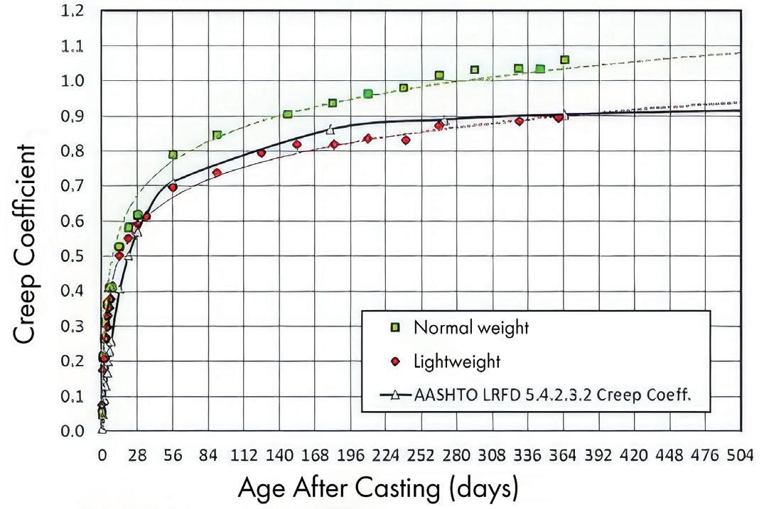
Graph comparing creep of structural lightweight concrete and normal-weight concrete. (Source: Precast/Prestressed Concrete Institute)
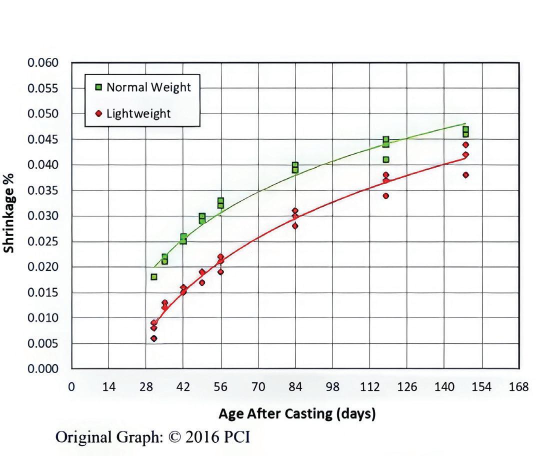
Graph comparing shrinkage of structural lightweight and normal-weight concrete. (Source: Precast/Prestressed Concrete Institute
any reduction in the weight of a long-span bridge can offer efficiencies in design. The reduced density of SLC offers significant benefits in such applications.
Because SLC decks and girders are lighter than normal weight concrete components of the same size, structural engineers can design greater span lengths for a given bridge cross-section than is possible with conventional concrete members. Steel girders will also typically have an increased span capability with an SLC deck unless deflections govern the design. Furthermore, seismic loads on bridges are computed based on the mass of the structure. Therefore, reducing the mass of the structure by using SLC can lower applicable seismic loads for which the bridge is to be designed. Additionally, using SLC will reduce the loads on bearings, substructures, and foundations, simplifying structural design and limiting required modifications and investments when reusing existing or providing new substructure and foundation elements.
Such was the case of the I-5 bridge span replacement project over the Skagit River in Washington. SLC prestressed concrete deck bulb tee girders were used to permanently replace a steel portal frame truss span of the I-5 bridge that had collapsed after being struck by an over-height truck. Engineers selected SLC deck girders, which include a full-depth bridge deck cast monolithically with pretensioned girders, for the permanent replacement span to provide a lighter solution. In doing so, the designers kept the total weight of the new span below 918 tons, which allowed them to reuse the existing foundations without reanalysis or strengthening, saving significant cost and time.
While dead loads are one aspect of design, structural engineers must also consider the compressive strength of a concrete member. The same concrete compressive strengths specified for design with conventional normal weight concrete are typically achieved with SLC. Concrete compressive design strengths above 5,000 psi (35 MPa) are often used in bridge projects and these strengths can also be achieved using SLC. In fact, the SLC concrete used for the prestressed concrete girders for the Skagit River Bridge span replacement used a design compressive strength of 9,000 psi, which was consistently achieved.
Along with density and design compressive strength, the modulus of elasticity is a critical parameter for structural engineers, particularly in bridge projects, as it reflects the stiffness of concrete. A higher modulus of elasticity contributes to greater stiffness, slightly reducing deflections under traffic loads and elastic shortening prestress losses. However, in some cases, such as seismic design, potential long-term deformations, or situations where differential settlement must be considered, a lower modulus of elasticity can be beneficial to provide flexibility and reduce loads on the structure.
For SLC, the pores in the ESCS particles reduce the aggregate stiffness and provide a closer match between the elastic properties of the aggregate and mortar. Comparing values of the modulus of elasticity computed using the equation in the latest edition of the American Association of State Highway and Transportation Officials (AASHTO) Load and Resistance Factor Design (LRFD) Bridge Design Specifications (BDS) shows that SLC, with a density of 115 pcf, is expected to have a modulus of elasticity of approximately 63 percent of the value for normal weight concrete with a density of 145 pcf, when both types of concrete have the same compressive strengths. Making the same comparison for SLC with a density of 100 pcf, the computed value of the modulus of elasticity is estimated to be 48 percent of the value for normal weight concrete.
The difference in performance is because, in normal weight concrete, the interaction between coarse aggregate (more than 35 percent by volume) and the mortar phase (approximately 65 percent by volume) yields a modulus of elasticity that is intermediate between the two components. For SLC, the pores in the lightweight aggregate particles reduce their stiffness and result in a closer match of elastic properties between the aggregate and mortar. This convergence of the properties of aggregate and mortar fractions also minimizes the strength penalty associated with air entrainment in SLC members compared to normal weight concrete members, where typically stiff normal weight aggregates can create a greater elastic mismatch, potentially leading to cracking around article particles.
Creep and shrinkage are other critical properties in projects where long-term deformation and volume changes can impact the structural performance of bridge infrastructure. Factors such as aggregate properties, paste volume, and curing conditions influence both quantities. Along with these aspects, the stress-to-strength ratio also impacts creep. A common misconception is that SLC exhibits greater creep and shrinkage than normal weight concrete;
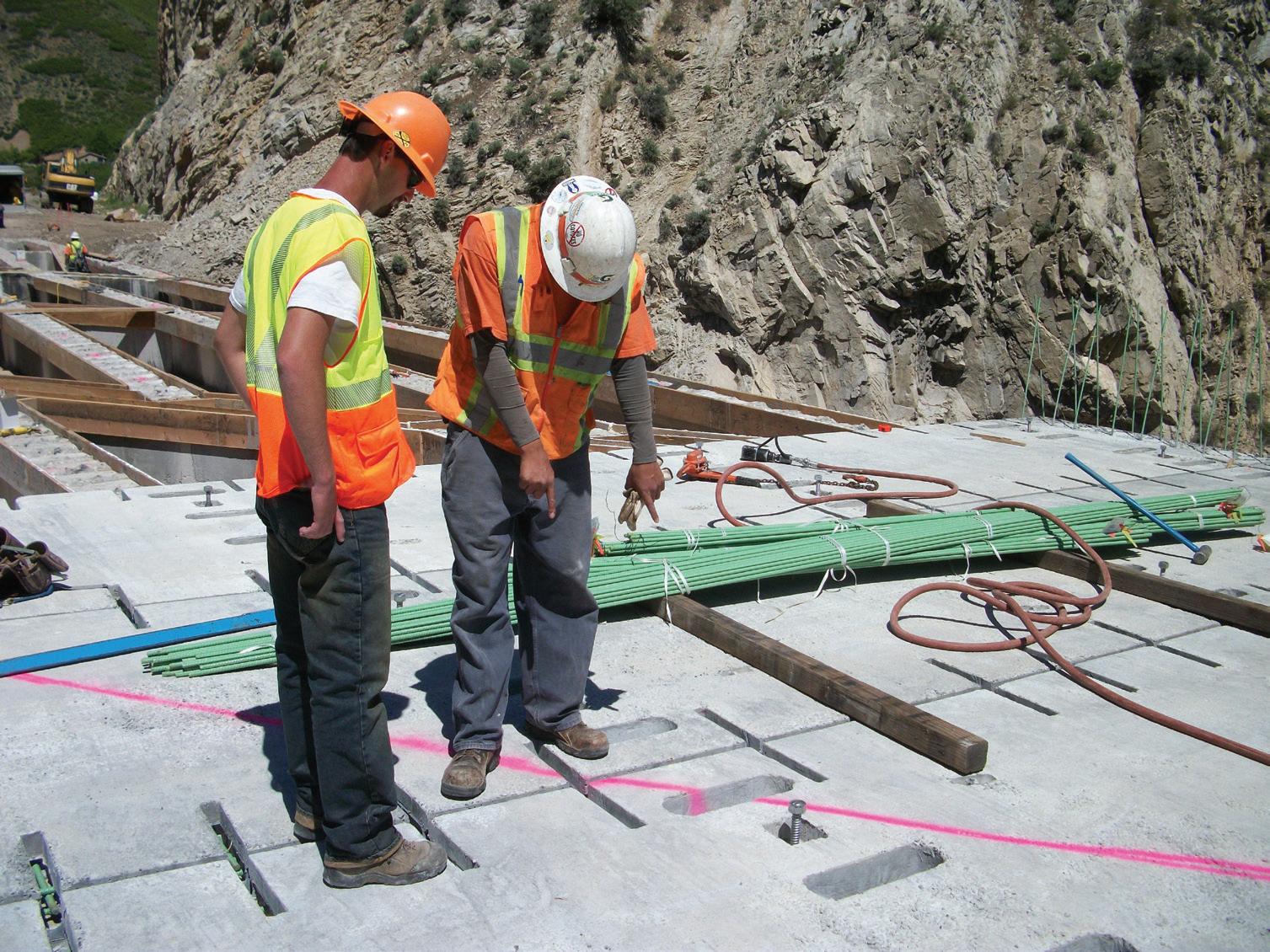
however, studies suggest otherwise. For context, creep, which is the long-term deformation of a material under sustained load, affects critical aspects of bridge design, including prestress losses, design of bearings and expansion joints, and force redistribution in composite structures.
A paper by Concrete Technology Corporation and Castrodale Engineering Consultants on three SLC bridges in Washington State suggests that higher-strength SLC exhibits creep behavior similar to, or even less than, comparable normal weight concrete mixes. For example, a lightweight concrete production mix with a design compressive strength of 9 ksi for a prestressed girder (used for the Skagit River Bridge span replacement) had less creep (and shrinkage) than a comparable normal weight concrete mix.
The same paper reported that the SLC girder mixture had less shrinkage than the comparable normal weight concrete. This behavior was unexpected because the SLC mixture had a total cementitious materials content of 935 lb/yd3. In comparison, the normal weight concrete mixture had a total cementitious materials content of only 752 lb/yd3. The SLC mixture, with a 24% higher total cementitious materials content compared to the NWC mixture, would typically be expected to have a significantly greater shrinkage. However, tests of both concrete mixtures demonstrated that the SLC mixture has a significantly lower shrinkage than the NWC mixture. With both a reduced shrinkage and modulus of elasticity, which are typical features of SLC, it is expected that SLC would experience reduced and/or delayed cracking, in applications where the concrete is restrained from freely shrinking.
Permeability in concrete components facilitates the ingress of

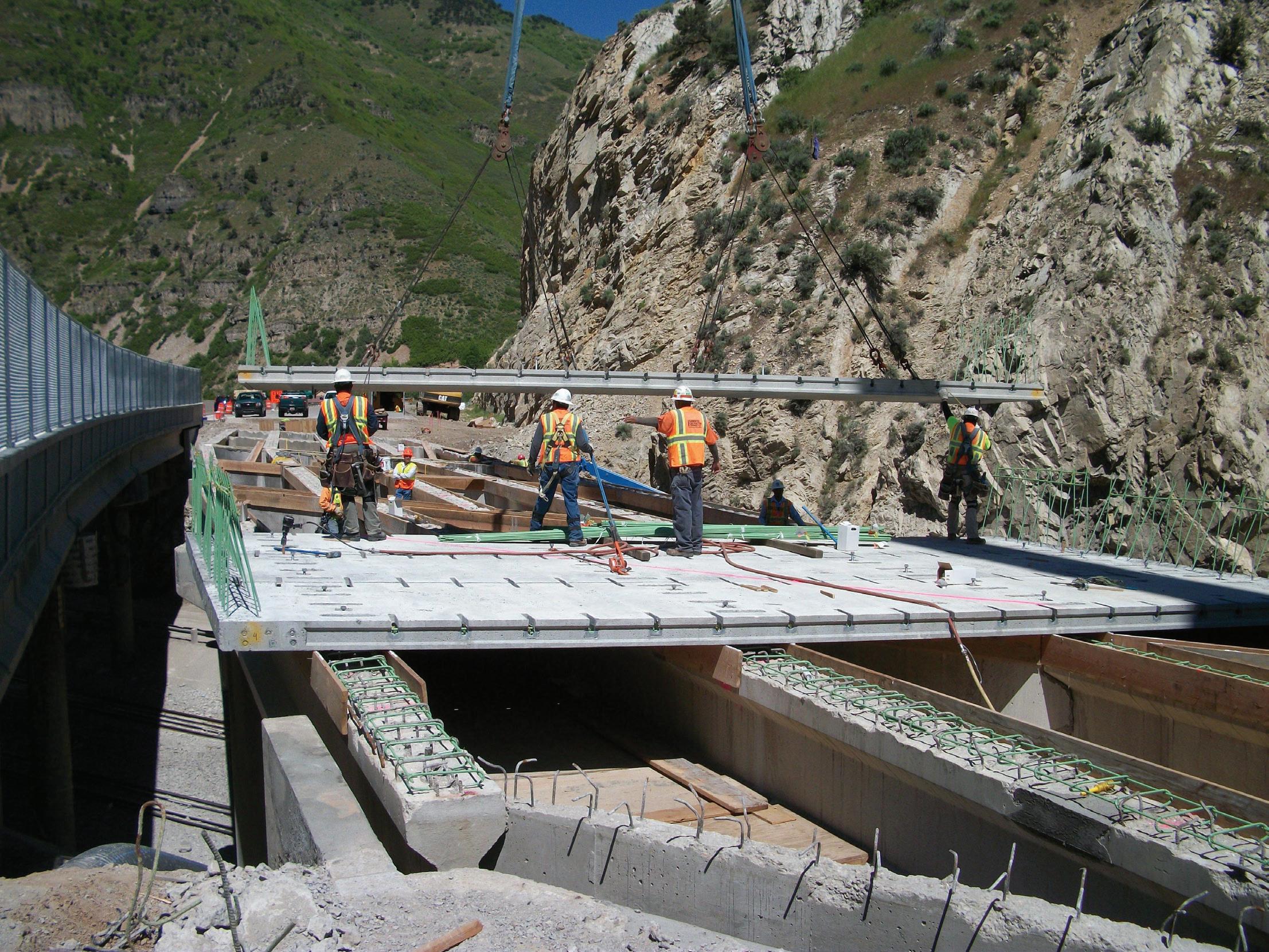
aggressive agents and increases vulnerability to chloride attack, which accelerates the corrosion of embedded steel reinforcement. Though many of the mechanical properties of precast SLC bridge members are comparable to those made with normal weight concrete, SLC exhibits superior durability, particularly in permeability resistance.
In concrete bridge components, elevated permeability often arises from a weak interfacial transition zone (ITZ) at the aggregate surface, which can contribute to microcracking in the ITZ that further increases permeability. However, components made with SLC benefit from the superior quality of the cementitious paste and internal curing, both of which are facilitated by using ESCS lightweight aggregates. The internal curing provided by moisture being released from prewetted lightweight aggregate results in a more complete reaction of cementitious materials, reducing permeability, shrinkage, and cracking. In contrast, NWC exhibits an abrupt transition at the dense aggregate/porous
cementitious matrix interface, which can exacerbate the risk of increased cracking and permeability.
SLC components have good resistance to freezing and thawing cycles when the SLC mixture is properly proportioned, batched, and placed. Once the lightweight aggregate is prewetted, moisture is released into the concrete as internal curing, improving the density of the ITZ and other concrete properties. The aggregate pores also act like little “relief valves” by providing additional space for the expansion of freezing water, if permeable concrete has allowed water to penetrate and freeze. This way, including ESCS lightweight aggregate helps reduce microcracking and permeability in bridge decks and improves resistance to freeze-thaw cycles. Because the benefits to SLC from internal curing and an improved ITZ depend on the lightweight aggregate being properly saturated, the concrete mix demands a higher degree of quality control than is typically required for normal weight concrete.
The ability to reuse existing substructure elements can eliminate the need for extensive demolition and reconstruction, significantly reducing costs and construction timelines.
Field studies and laboratory tests underscore these
advantages. Reports that evaluate the performance of bridge decks in Virginia demonstrate that SLC decks exhibit less cracking compared to decks constructed with normal weight concrete, which has resulted in the inclusion of SLC mixtures as one of two approved options for low-shrinkage deck concrete in the Virginia DOT Road and Bridge Specifications since the 2016 edition.
The reduced permeability, as well as improved resistance to microcracking and freeze-thaw cycles, enhance the durability of SLC bridge members. Using SLC members can help structural engineers provide better protection for embedded reinforcement against corrosion, which in turn, safeguards the long-term structural integrity of our country’s bridge infrastructure.
Even after structural engineers educate project teams about the benefits of SLC components in long-term performance, some engineers may be skeptical about using SLC components due to the slightly higher cost. Evaluating the economics of SLC members in bridge repair and rehabilitation needs to go beyond just the cost of the constituent materials and components, and instead focus on the value that the use of SLC brings to the project over its extended service life.
A report by the FHWA has estimated the cost effect of using SLC or normal weight concrete in a precast segmental box girder bridge. It reported savings in the schedule due to the concurrent construction nature of the members as well as the cost. In application, the reduction in dead loads provided by SLC leads to more efficient designs, allowing for extended span ranges, wider girder spacings and shallower girder sections. Such design optimizations can significantly reduce material usage and construction costs while maintaining or improving long-term performance.
For example, the Wabash River Bridge was an early project in Indiana that used precast lightweight concrete girders with both pretensioning and post-tensioning to extend the span length to 175 ft. Using SLC components resulted in savings of $1.7 million on the $9.4 million project. In a review of SLC use in California, Thompson and Wu compared a typical two-span overpass design for a box girder superstructure that uses normal weight concrete versus SLC. Results showed that the footing size of the SLC bridge was smaller, with fewer piles, resulting in a 20 percent savings in overall foundation cost, including the column, footing, and piles.
The savings on structural systems when using SLC components are particularly advantageous for rehabilitation projects. As mentioned earlier in the article, the ability to reuse existing substructure elements can eliminate the need for extensive demolition and reconstruction, significantly reducing costs and construction timelines. In cases of bridge widening or load rating improvements, the use of SLC may facilitate these upgrades without necessitating modifications to the existing superstructure or substructure. This adaptability can be especially valuable when updating aging infrastructure, which is often heavily traveled, enabling enhancements to be constructed without requiring modification of the existing structure, while also minimizing disruption to the users of the facility.
Additional information on using SLC in bridge construction, including projects, papers, and reports mentioned in this article, can be found on Expanded Shale, Clay and Slate Institute’s (ESCSI) website: www.escsi.org/structural-lightweight-concrete/.
The reduced design loads on bearings, substructure elements and foundations further streamline logistics and improve overall efficiency. The reduced weight of SLC components may allow a greater number of small precast components to be transported in each truckload. The longer segments possible due to lighter weight minimize the number of fabricated pieces required for a project, accelerating project delivery and reducing the number of joints in the structure. Fewer joints translate to improved durability and reduced maintenance over the bridge’s lifecycle.
This approach also results in fewer loads being delivered to the construction site, improving safety for both construction personnel and the traveling public. The reduction in transportation leads to not only lower costs associated with traffic control but also lessens traffic congestion. The reduced weight of SLC components enables the handling of larger precast pieces without exceeding the capacity of existing hauling or lifting equipment, which further optimizes delivery schedules and enhances construction efficiency.
As structural engineers continue to navigate performance requirements with budget constraints in bridge repair and rehabilitation projects, SLC emerges as a forward-thinking solution that delivers both immediate construction advantages and long-term performance benefits. The proven track record of SLC use in projects across the country and its comprehensive technical advantages make it an important consideration for bridge infrastructure projects where efficiency, durability, and cost-effectiveness are primary objectives. ■
Michael Robinson is the Senior Technical Consultant to the sales department at Stalite Lightweight Aggregate, who is a member of the Expanded Shale, Clay and Slate Institute (ESCSI)—an international trade association for manufacturers of rotary kiln-produced expanded shale, clay and slate lightweight aggregate.
Special thanks to Reid Castrodale, PhD, PE, Director of Engineering at ESCSI, for his valuable expertise and insights.
The Brick Industry Association (BIA) awarded the 2024 Brick in Architecture Awards, the leading international design competition featuring fired-clay brick. The winning projects span the United States, Canada, China, England, Mexico, and Russia. Judged by a jury of peers, winners include Best in Class, Gold, Silver and Bronze. The overall Craftsmanship Award honors a mason or team of masons that skillfully installs brick in an artful or unique way.

The Best in Class winners include:
Commercial (and Craftmanship)
Leica Gallery, New York, New York
Architect: Format Architecture Office
Brick Manufacturer: Hebron Brick Company
Mason Contractor: LTM Construction
Education—Colleges & Universities
Rothschild College at Vanderbilt University, Nashville, Tennessee
Architect: David M. Schwarz Architects, Inc.
Brick Manufacturer: Glen-Gery, Endicott Clay Products
Mason Contractor: IMS Masonry
Education—K-12
James Lawson High School, Nashville, Tennessee
Architect: Hastings Architecture
Brick Manufacturer: Watsontown Brick
Brick Distributor: Alley-Cassetty Brick
Mason Contractor: A&R Masonry
International
Gainsborough's House Museum, Sudbury, England
Architect: ZMMA
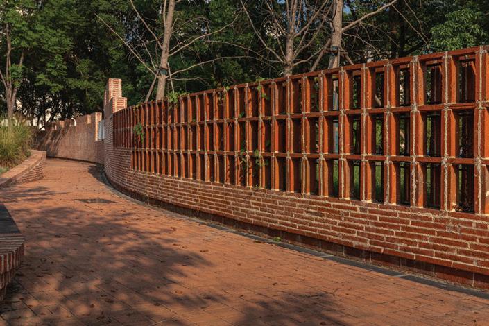

Paving & Landscaping
The Beikun Garden, Shanghai, Jiangsu
Architect: RUAN Studio, School of Design
Mason Contractor: Shanghai Grand Neobay Investment Development Group
Residential—Multifamily
Anagram, New York, New York
Architect: SLCE Architects; INC Architecture & Design
Brick Manufacturer: Yankee Hill
Brick Distributor: Belden Tri-State Building Materials
Mason Contractor: Vema Group
Residential—Single Family
2100 Lombard, Philadelphia, Pennsylvania
Architect: LO Design
Brick Manufacturer: The Belden Brick Company
Brick Distributor: Belden Tri-State Building Materials
Mason Contractor: New MB General Contractors
I
n areas of the country where dangerous tornadoes and severe weather occur more frequently, universities are incorporating reinforced rooms, or storm shelters, in their residence hall designs to provide an extra layer of protection for students.
These tornado-safe rooms are typically small, above- or belowground structures made of concrete, masonry or steel that are proven to withstand extreme winds, even those produced by EF-4 or EF-5 tornadoes.
Javier Esteban, Principal at St. Louis-based KWK Architects, suggests that universities collaborate with their architectural firms to determine a reinforced room design that best accommodates their budgets, structures and student population.
Ideally, reinforced rooms should be designed and constructed based on the standards and codes for tornado and hurricane storm shelters developed by the International Code Council (ICC) 500, in partnership with the National Storm Shelter Association (NSSA), said Esteban, but that is not always feasible for a variety of reasons.
“Many times the restrictions in terms of ventilation, structure, and exit requirements make designing to these codes cost-prohibitive for universities. In those instances, it is still possible to design for student safety via a compromise where some public areas of the residence hall have strengthened or reinforced structures, doors, and windows,” he said.
KWK Architects has designed reinforced rooms for several universities within the country’s "Tornado Alley" where twisters are more common:
• Headington and Dunham Residential Colleges at the University of Oklahoma (Oklahoma averages 68 tornadoes per year).
• University Commons residential complex at Missouri S&T (Missouri experiences an estimated 45 twisters annually).
• Victor E. Village at Fort Hays State University in Kansas (Kansas reports an average of 96 tornadoes per year).
A reinforced room should be designed to stand up to high winds on its own, independent of the building structure surrounding it, said Esteban.
“It is critically important to maintain the structure of the reinforced area so that should a building collapse occur, it does not affect the integrity of the reinforced space, and its occupants remain safe,” said Esteban.
The Federal Alliance for Safe Homes (FLASH) has outlined the different types of tornado-safe room options available and the materials used to build them:
1. Cast-in-Place Concrete —these
rooms are assembled on-site using removable forms, rebar and concrete to create the walls and ceilings. The forms can be fitted with liners to create concrete exterior surfaces that look like siding, brick or stone.
2. Insulating Concrete Forms (ICFs)—These rooms are created using foam blocks that contain steel reinforcement, fitted together and filled with concrete. The foam is a permanent part of the room and provides insulation to the building. Interior and exterior finish options include drywall, sheet rock or siding.
3. Concrete Masonry —These safe rooms are constructed of individual blocks, set in place with rebar and fully grouted. Two rows of steel at the top of the wall hold the assembly together. There are a variety of texture and finish options available.
4. Precast Concrete —This room is formed off-site and delivered to a building for installation. It can be located virtually anywhere in a new building and is anchored using steel angles and bolts. Precast concrete can be finished in a variety of colors and textures using form liners.
5. Prefabricated Above-Ground Steel —These prefabricated safe rooms typically cost less than site-built safe rooms. Considerations must be made to ensure that this room is placed on a safe and sturdy foundation.
Esteban also suggests that reinforced room designs incorporate emergency lighting, electrical outlets, fire extinguishers, first aid kits, heating and air conditioning, and an AED defibrillator. When not in use during emergencies, residence hall storm shelters can serve as lounges and study areas for students.

Build With Strength, an initiative of the National Ready Mixed Concrete Association (NRMCA), has announced the recipients of the 2025 Concrete Innovation Awards. This annual program highlights outstanding achievements in the design and construction of concrete structures where NRMCA member companies played a significant role in supplying products or services. Winners represent exemplary projects that leverage innovative concrete technologies to enhance sustainability, reduce embodied carbon and improve performance. In this judging cycle, 11 winners were selected:
• AWS Data Center (New Carlisle, IN) was honored for its innovative use of low-carbon concrete in the construction of a large-scale data center campus, setting a standard for sustainable development in the tech industry. NRMCA Producer member Ozinga provided the concrete for the project.
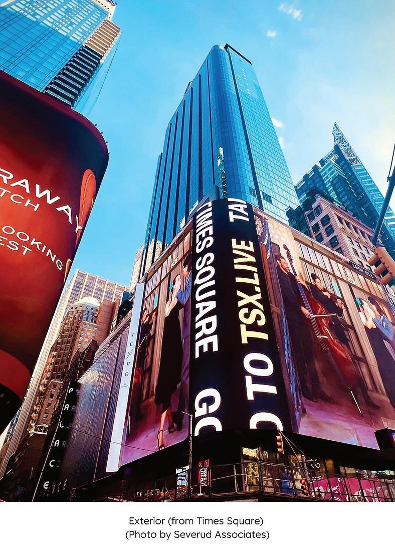
• Central City Parallel Tunnel (Minneapolis) was celebrated for its pioneering use of eco-friendly concrete technologies in a large-scale water management infrastructure project, demonstrating exceptional performance and environmental responsibility. NRMCA Producer member Cemstone Products Company designed and supplied 23,000 cubic yards of highly technical concrete for this project.
• Intuit Dome (Inglewood, CA) was honored for its use of cutting-edge concrete applications to support the construction of a state-of-the-art sports arena with a focus on minimizing carbon emissions while maximizing structural resilience. NRMCA Producer member CalPortland provided the concrete for the project.
• Lane Construction I-40/I-77 Concrete Paving Project (Iredell County, NC) was celebrated as the first project in North Carolina to utilize Type IL cement. This milestone reflects a major step toward reducing the carbon footprint of infrastructure projects. U.S. Roanoke Cement Company (RCC) was the NRMCA member and cement supplier.
• Lower Carbon Content Concrete Pavements – MnROAD (Albertville, MN) was acknowledged for its pioneering research and implementation of lower-carbon concrete pavements, showcasing scalable solutions for sustainable road construction. The following NRMCA members were crucial to the success of the project: Holcim, Ozinga, Continental Cement, Cemstone, the Aggregate and Ready Mix Association of Minnesota, American Engineering Testing, Inc. and Braun Intertech.
• New York State Department of Transportation Southern Tier Bridge Replacement and Safety Project (Whitney
Point, NY) was recognized for specifying low-carbon concrete and incorporating glass SCMs (supplementary cementitious materials) to achieve sustainability goals for a $21.2 million bridge replacement project. NRMCA member Barney & Dickenson was the leader in this project.
• One Milestone (Boston), a research and development hub, was celebrated for its use of advanced concrete technologies to reduce embodied carbon in a major mixed-use development while enhancing long-term durability. NRMCA Producer member Boston Sand & Gravel supplied the concrete on this project.
• SFO Terminal 3 West (San Francisco) was cited for its landmark project at the San Francisco International Airport that achieved significant reductions in embodied carbon while meeting rigorous sustainability standards. The concrete used aggregates from NRMCA member Martin Marietta and concrete produced by NRMCA Producer member Bauman Concrete.
• TSX Broadway and Palace Theater Redevelopment (New York) was acknowledged for its extensive use of low-carbon concrete in the revitalization of an iconic Times Square venue, balancing historic preservation with modern sustainability practices. The project used products from NRMCA member Heidelberg Materials.
• TVRM’s ‘Proving Grounds’ for Low-Carbon Concrete (Norfolk, VA) was recognized for its groundbreaking advancements in testing and developing AI-generated lowcarbon concrete, showcasing the potential for transformative change in the construction industry. NRMCA Producer member Titan Virginia Ready-Mix provided the concrete for the test paving site and NRMCA member Roanoke Cement Company provided the cement.
• The City of Salt Lake and Utah Transportation Authority: Electric Bus Charging Station (Salt Lake City) was recognized for its innovative use of concrete in the development of an electric bus charging station, contributing to the region's clean transportation goals. NRMCA member Roman Cement used a patented technology to re-design a standard concrete mix, driving up performance and making concrete more sustainable.
More details about the nominees and winners, including images, can be viewed at www.concreteinnovations.com/2025winners.
Build With Strength is an initiative of the National Ready Mixed Concrete Association that seeks to educate the building and design communities and policymakers on the benefits of ready mixed concrete and encourage its use as the building material of choice for buildings.
Elevate Structures announces new executive staff to meet growth demandsl
The Georgia-based firm is expanding its construction expertise with the addition of Ben Aune as Vice President of Construction and the promotion of Darby Owenby to Vice President of Operations. Aune will lead Elevate Structures’ construction and field operations, ensuring projects are executed safely, efficiently, and to the highest quality standards. Owenby will lead Estimating, Engineering & Drafting, and Pre-Construction, ensuring seamless coordination across the early stages of project development.
ACI Foundation unveils new process for identifying and funding
The new format will provide balanced support for both defined and undefined research, ensuring a broader engagement to identify critical industry needs, and prioritizing essential solutions for challenges that affect the entire sector. Project ideas may be submitted at any time throughout the year, with reviews, assessments, and funding decisions made according to an annual schedule. The ACI Foundation may also create and post requests for proposals (RFPs) based on defined topics. Proposals will be evaluated based on their relevance, potential impact, supplementary support, overall quality, and the capability of the research/project manager. For more details about the new process, visit www.acifoundation.org/research/solicitations.aspx.


The multi-disciplinary consultancy has expanded its structural engineering presence in the South West U.K., welcoming a new associate director to spearhead the team. Ricardo Sequeira brings more than two decades of experience to the firm, having led complex projects across high-rise residential and commercial developments, and is a chartered member of the Institution of Structural Engineers. He will also play a key role in client engagement and business development, further expanding the firm’s footprint in the region.
Co-authored by Arup and the U.S. Green Building Council California, the new California Wildfire Rebuilding Guide offers practical and sustainable solutions to help wildfireaffected communities rebuild with resilience, safety, and long-term climate considerations. It provides a comprehensive overview that outlines key concepts, major decisions, and instructions so that it is accessible and digestible for a general audience. It also provides a variety of decision-making categories, including placement, envelope design, outdoors, building systems, green innovation, and community.
Visit https://usgbc-ca.org/ to download the guide for free.


The National Council of Structural Engineers Associations (NCSEA) is pleased to announce its 2025-2026 Board of Directors, who will lead the organization’s efforts to advance the structural engineering profession. Each term begins April 1 and concludes March 31 of the following year.
Jami Lorenz, PE, of Haselden Construction and the Structural Engineers Association of Montana, serves as the new President of the NCSEA Board, bringing a wealth of leadership experience to the position. Brian Petruzzi, PE, of Meta and the Structural Engineers Association of Metropolitan Washington, will transition into the role of Vice President, while Ken O’Dell, SE, of MHP, Inc. Structural Engineers and the Structural Engineers Association of Southern California will begin his second year at Secretary. Cervente D. Sudduth, PE, ENV SP, of DuBois Consultants, Inc. and the Structural Engineers Association of Kansas & Missouri, will now serve as Treasurer after a two-year stint as Director.
A special thank-you goes to Christopher Cerino, PE (STV, Inc./ Structural Engineers Association of New York), who now assumes the role of NCSEA Past President.
The 2025-2026 Board also welcomes two new Directors to its ranks: Andrea Reynolds , PE, SE (SmithGroup/Structural Engineers Association of Michigan), and Chad Mitchell , PE



(KPFF Consulting Engineers/Structural Engineers Association of Colorado). They join current Directors Michelle Ryland , SE, RA (Klein & Hoffman, Inc./Structural Engineers Association of Illinois) and Andrew Lovenstein , PE, SI (J. S. Held LLC/Florida Structural Engineers Association).
NCSEA extends its sincere appreciation to Ryan Kersting, SE, FSEAOC (Buehler Engineering/ Structural Engineers Association of Central California) and Angelina V. Stasulis, PE, SE (Shear Structural/ Structural Engineers Association of Georgia) for their dedicated service as members of the Board. Their leadership and commitment have helped shape and support the direction of NCSEA.
The new Board is poised to continue NCSEA’s mission. NCSEA remains committed to fostering innovation, collaboration, and professional development across the structural engineering community.
“Our volunteer leaders bring a deep understanding of the profession and an unwavering commitment to our mission,” said Al Spada, NCSEA CEO and Executive Director. “This year’s Board reflects a dynamic mix of experience, fresh perspective, and passion for advancing structural engineering. We’re also deeply grateful to our outgoing Board members and past leaders, whose dedication and vision have helped build a strong foundation for the future.”





The NCSEA Foundation has announced its Board of Directors for 2025-2026. This year’s Board brings together leaders from academia, private practice, and the broader profession to guide the Foundation’s mission. As the charitable arm of the National Council of Structural Engineers Associations (NCSEA), the Foundation strives to advance the science and practice of structural engineering.
Tom Grogan, PE, SE, F.ASCE (Retired/Florida Structural Engineers Association), will serve as Foundation President. Joining him in leadership are Dr. Judy Liu (Oregon State University/ Structural Engineers Association of Oregon) as Vice President and Ron Klemencic, PE, SE, Hon. AIA (Magnusson Klemencic Associates/Structural Engineers Association of Washington) as Secretary/Treasurer.
Also serving on the NCSEA Foundation Board are:
• Brian Petruzzi, PE (Meta/Structural Engineers Association of Metropolitan Washington)—Director and NCSEA BOD Vice President
• Cervente Sudduth , PE (Dubois Consultants/Structural Engineers Association of Kansas & Missouri)—Director and NCSEA BOD Treasurer
• Sara Roberts, PE, SE (KPFF Consulting Engineers/Structural Engineers Association of Washington)—Director
• Vicki Arbitrio, PE (Gilsanz Murray Steficek, LLP/Structural Engineers Association of New York)—Director


Secretary/Treasurer


• Lauren Piepho , PE (HGA/Minnesota Structural Engineers Association)—Director
• Marcia Camarda , PE, LEED AP (SK&A Structural Engineers/Structural Engineers Association of Metropolitan Washington)—Director
• Kim Olson , PE (Nucor Corporation/Structural Engineers Association of Colorado)—Director
• Natalie Tse, SE, LEED AP (Tipping Structural)—Director
A special thank you goes to Tricia Ruby (Ruby + Associates, a Degenkolb Company/Structural Engineers Association of Michigan) who continues her service as Past President, and Jami Lorenz , PE (Haselden Construction/Structural Engineers Association of Montana), President of the NCSEA Board of Directors, who will serve in an ex-officio capacity.
Through its Board-led efforts, the NCSEA Foundation supports initiatives that drive technical advancement and increase public awareness of the vital role structural engineers play in our communities.
As a champion of innovation in the profession, the Foundation invests in emerging areas such as artificial intelligence and embodied carbon reduction—both critical to the future of the built environment. It also leads NCSEA’s We SEE Above & Beyond(opens in a new tab) campaign, which raises the profession’s visibility by spotlighting how structural engineers help create safe, resilient, and vibrant communities.
For more information about the NCSEA Foundation and how to get involved, visit www.ncsea.com/foundation.

Ron Klemencic, PE, SE
Magnusson Klemencic Associates



Over600 middle schoolers in Tucson explored STEM through interactive activities at Arizona Stadium, learning to “engineer a football game.”
Why it matters: STEM education is crucial for opening career paths in industries needing support.
• Events like these demonstrate realworld applications, inspiring students to pursue engineering.
By the numbers: Students engaged with four stations covering transportation, utilities, and structural engineering, guided by industry professionals. What they’re saying: “STEM can affect their lives and help them solve problems,” said Mike Olson, civil engineer and event organizer.

• Richard Dwyer, an 8th grader, expressed excitement for his future in electrical or software engineering. “I enjoy how hands-on it is, and
Withrespect to year-over-year growth in individual markets, the start of the year shows a market shift in growing markets versus declining markets. The Water sector saw growth in both Supply and Sewage & Waste disposal. Education entered the top markets, while Amusement and Public Safety continue to see strong growth. A noteworthy change is that this is the first time Manufacturing did not see double-digit growth since the fall of 2021.
For the sectors with the lowest levels of growth, Lodging and Commercial, continue to see declines due to interest rate sensitivity while Highway & Street and Health Care see negative growth for the first time since the spring of 2021. It is unclear how much of this is due to fiscal policy changes.

I enjoy learning from someone who knows what they’re talking about. I want to be either an electrical or software engineer when I grow up. So, I want to do all the lights and stuff.”
The bottom line: This day was made possible by the dozens of volunteers in the workforce who showed up for the students. “Science, technology, math, and engineering all work together to really open up a lot of avenues for these kids,” Olson said.
Video of the event can be seen on YouTube at www.youtube.com/ watch?v=6R_QplnapXU.
For more news like this, sign up now to get updates from the Engineering Workforce Consortium by scanning the QR code.
JoinCASE at ACEC’s 2025 Annual Convention & Legislative Summit.

ACEC’s 2025 Annual Convention & Legislative Summit will take place May 18–21 in Washington, DC, at the Grand Hyatt, just steps from Capitol Hill. This year’s legislative agenda will have a profound impact on structural engineering firms, with Congress prioritizing tax reform, workforce policies, infrastructure investment, and regulatory streamlining. Key tax policies affecting engineers, including the 21% corporate tax rate, the 20% deduction for S corporations and passthrough firms, and the restoration of full R&D expense deductibility, will be at the center of the debate.

In addition to critical advocacy efforts, the Convention will host a CASE Roundtable with the MEP Coalition, where firm leaders will discuss pressing business issues, including risk management, liability concerns, and industry best practices.
With 2025 shaping up to be a transformational year for engineering policy, your participation in ACEC’s Annual Convention & Legislative Summit is more important than ever. Join us in Washington, DC, to connect with industry leaders, advocate for your firm’s future, and stay ahead of the changes that will define the business of structural engineering for years to come.
Explore CASE’s top publications that inspire and inform professionals like you. From cutting-edge research to actionable insights, this year’s bestsellers are not to be missed. Plus, if you’re not a CASE member, don’t forget to use your discount code NCSEASEI2022 at checkout for exclusive savings.
The Guideline is an update of the previous edition to bring it current with the requirements of the 2018 International Building Code. The Guideline describes the roles and responsibilities of the parties involved in the special inspection and testing process, how to prepare a special inspection and testing program, the necessary qualifications of the special inspectors, how to conduct the program and who should pay for the special inspections and test. The Appendix contains sample forms for specifying special inspections and tests and sample letters to be filed with code-enforcement agencies after the program is completed.
CASE 962 – National Practice Guidelines for the Structural Engineer of Record The purpose of these Guidelines is to give firms and their employees a guide for establishing Consulting Structural Engineering Services and to provide a basis for dealing with Clients generally and negotiating Contracts in particular. Since the Structural Engineer of Record (SER) is normally a member of a multi-discipline design team, these Guidelines describe the relationships that customarily exist between the SER and the other team members, especially the team leader. Further, these Guidelines promote an enhanced Quality of Professional Consulting Structural Engineering Services while also providing a basis for negotiating fair and reasonable compensation. This edition was updated to include information on responsibilities for drawing releases for steel mill orders and also for Guaranteed Maximum Price releases.
The complete library of coalitions documents is free to current ACEC Coalitions members. For information on joining ACEC Coalitions, contact Alec Cherney, Coalitions Coordinator, at acherney@acec.org.
The current construction spending market for health care is worth $68 billion, up 3 percent from 2023, according to FMI. An aging population, growing mental health concerns, the increase in artificial intelligence capabilities, and rising obesity rates will drive demand for additional medicines, services, and facilities including hospitals, outpatient facilities, and medical office buildings. Here are the top five trends impacting the market today.
1. The surge in mental illnesses demands more facilities: One in 5 American adults (approximately 57.8 million) experienced mental illness in 2021, according to the National Alliance on Mental Illness. In 2023, 50 percent of adults ages 18 to 34 reported experiencing
mental illness, the highest rate among the population, according to the American Psychological Association. Diagnoses of anxiety and depression increased by 25 percent during the first year of the COVID-19 pandemic, the World Health Organization reports. This led investors to begin acquiring behavioral health properties at a rapid pace, with investments worth $3 billion in the last 10 years, according to Colliers. This directly resulted in increased investment in three in-demand facility types: outpatient, inpatient, and residential.
Read more in Engineering Inc. magazine for ACEC members at www.acec.org/resources/engineering-inc-magazine/.
Education has the power to transform lives, but for many talented and hardworking students, financial barriers stand in the way of their dreams. The CASE Scholarship Fund is dedicated to breaking down those barriers—ensuring that every deserving student has the opportunity to pursue higher education, regardless of their financial circumstances. Right now, we have an opportunity to make a real and lasting impact. Every dollar raised goes directly toward helping students achieve their academic goals, empowering the next generation of leaders, innovators, and changemakers. These scholarships don’t just fund tuition—they fuel ambition, progress, and hope for a brighter future.

Do you know an aspiring engineer who could benefit from this opportunity? Share the CASE Scholarship with them and help open the door to a world of possibilities. To find out how to apply search “Scholarship” in the search bar on ACEC’s Home page. We need your support to continue this mission. Whether you contribute $10 or $1,000, your donation makes a difference. Together, we can open doors, create opportunities, and change lives. Join us in investing in the future. Donate to the CASE Scholarship Fund by scanning the QR code today.
The latest ASCE Report Card gives U.S. infrastructure a ‘C’ grade—an improvement from 2021’s ‘C-’ and the highest rating since the assessment began in 1998. Recent federal investments, particularly from the Infrastructure Investment and Jobs Act, have spurred progress. However, a $3.7 trillion funding gap remains, up from $2.59 trillion in 2021, highlighting the continued need for investment.
To ensure infrastructure remains a legislative priority, citizens should advocate for sustainable funding and modernization. Investing in infrastructure strengthens the economy, supports American jobs, and enhances resilience and connectivity for the future.

Curiousabout how the Structural Engineering Institute (SEI) is driving the future of sustainable structural engineering? SEI is leading the charge toward a low-carbon, resilient built environment, and now you can gain key insights from industry experts—completely free on our YouTube page (youtube. com/@structuralengineeringinsti8674).
These insights come from SEI’s recent Sustainability Symposium, where experts shared practical strategies and real-world solutions for a more sustainable future.
• Fortifying Your Sustainability Toolkit Learn essential strategies to seamlessly integrate sustainability into your practice.
• The Realities of Construction—Explore the challenges and practical solutions for implementing sustainable practices in realworld projects.
• What Success Looks Like—See how engineers are achieving sustainability goals today and what’s on the horizon for the industry.
We’re excited to continue the conversation at SEI’s Toward Carbon Zero: Summit & Symposium, this June 26-27. Registration is now open! Join us as we push forward toward a net-zero future: go.asce.org/ towardszerocarbon2025.
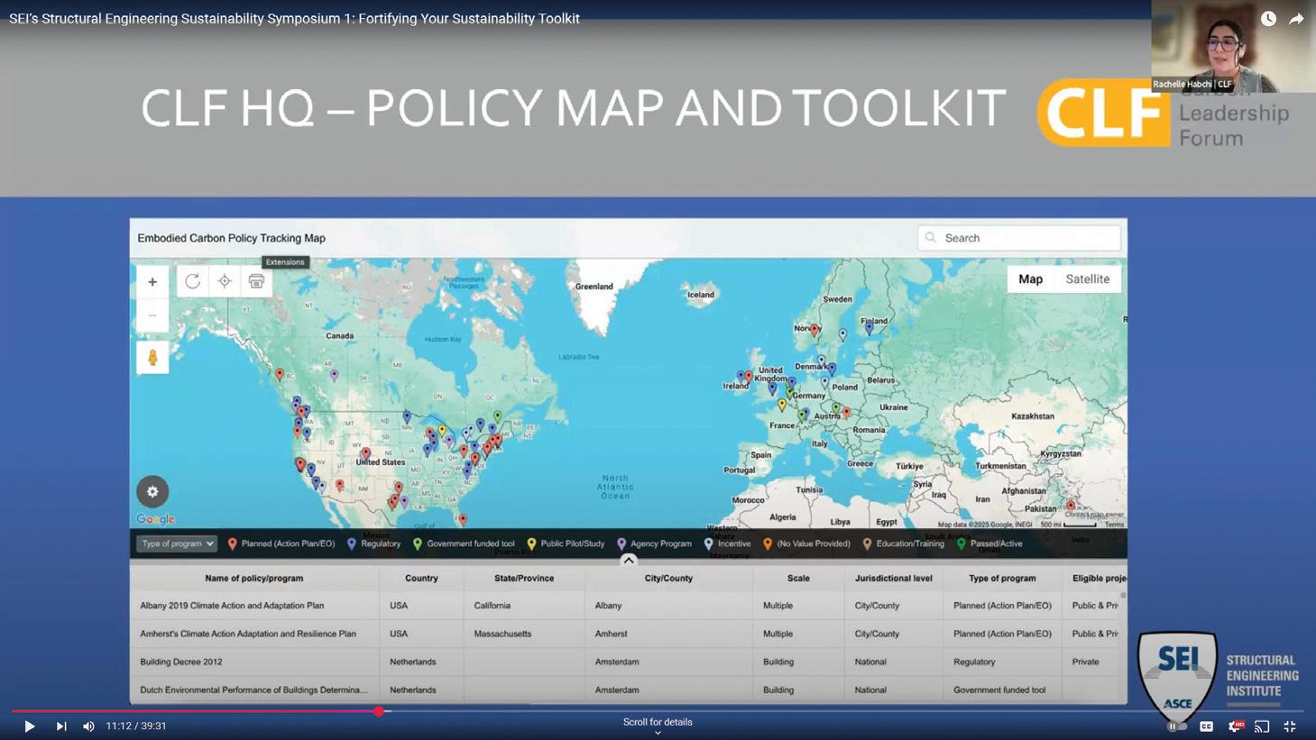
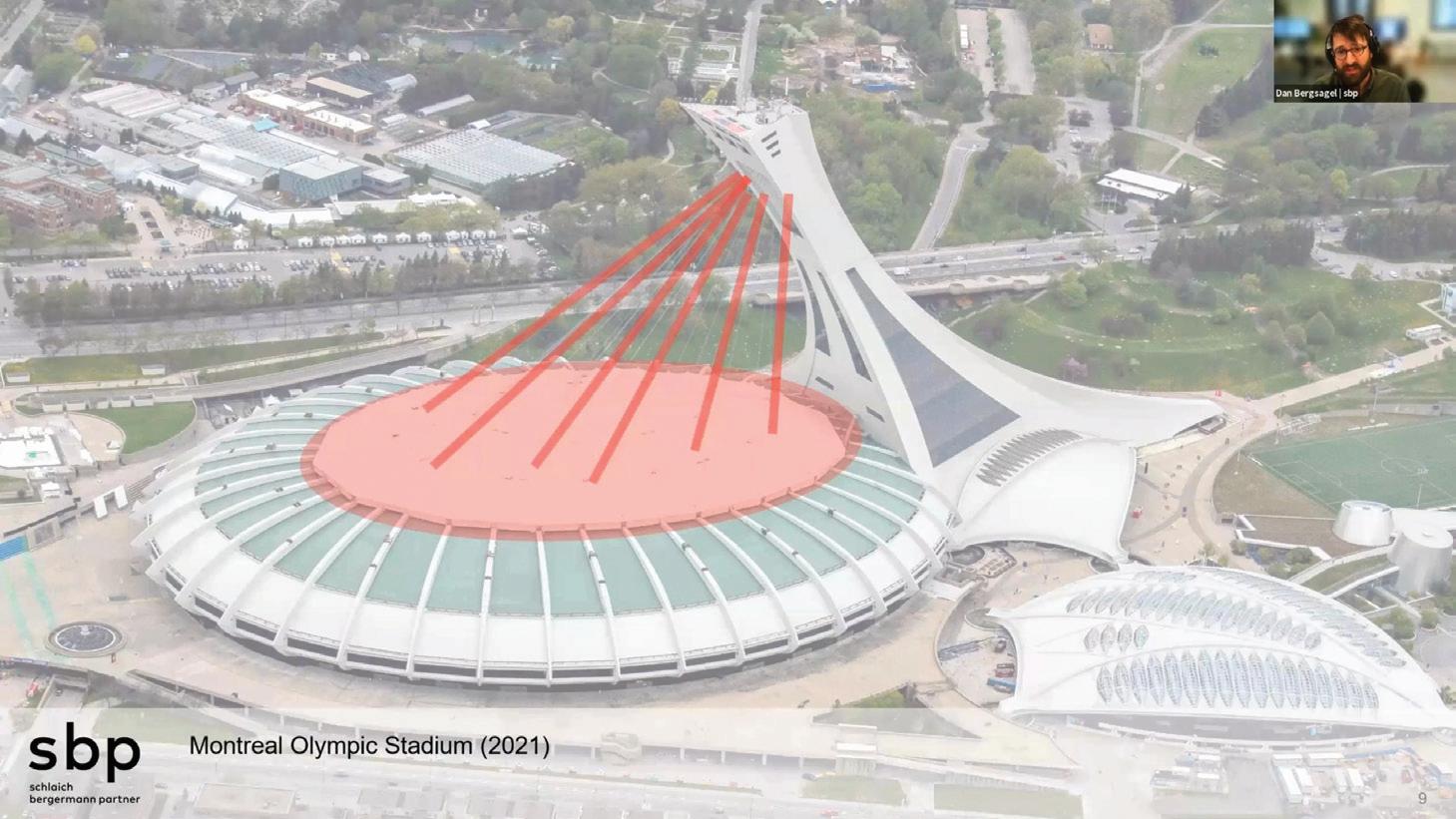
The generosity of SEI Futures Fund donors fuels the future of structural engineering. The Futures Fund provides scholarships that open doors for students and young professionals, helping them gain leadership experience and expand their expertise. It also supports impactful programs like last year’s Towards Carbon Zero Bootcamp, which equips engineers with the tools to drive sustainability, and local chapter events—such as SEI East Central Florida’s recent networking event (go.asce.org/seilocalchapterevent)—that connect and inspire our community.
Together, we’re strengthening SEI’s legacy and shaping the next generation of structural engineers. See the full donor list at go.asce.org/seifuturesfund.
The SEI Structures Congress NTPC invites abstracts and session proposals for 2026. Submissions are due June 4, 2025, at 10:00 p.m. ET—no extensions.
Topics include leadership, innovation, resilience, sustainability, emerging technologies, and evolving codes. Professionals from all disciplines are welcome.
Accepted presenters and moderators must register and attend. Limit two submissions per person. Visit https://2026.structurescongress.org/ call-proposals.

By Dr. Frank Griggs, Dist. M. ASCE
The 50-mile long Atchison & Topeka Railroad was chartered in 1859 to run between the two Kansas Cities. Atchison was on the west bank of the Missouri River, and Topeka to the southwest was on the Kansas River. Not much was done until Lincoln and Congress passed the land grant bill to support the construction of railroads in 1863. The grant stated the line had to reach the Colorado State line by March 3, 1873. It was later named the Atchison, Topeka and Santa Fe Railroad on November 23, 1863, by Cyrus Holliday when it sought to extend its lines to Santa Fe, New Mexico, along the famed Santa Fe Trail.
Construction started in 1868 and reached the state line on December 28,1872, several months before the date set by Congress. It reached Pueblo, Colorado, in 1876 and Santa Fe in 1880 where it connected with the Southern Pacific Railroad. Later, a line was completed southerly to Kansas City along the Missouri River. From there it sought a connection with Chicago. It owned a part of the Kansas City Belt Line that got it 8 miles east of the city. Starting from Chicago, the Chicago, Santa Fe and California Railroad ran southerly to Pekin, Illinois. The AT&SF obtained rights to run over that line to Ancona, Illinois.
What it needed then was a 350-mile line to connect Sibley, Missouri, to Ancona, Illinois.
The line required major bridges across the Mississippi, Des Moines, and Missouri Rivers. The line chose Octave Chanute at their Consulting Engineer. Chanute had already designed and built major bridges at Kansas City, Missouri, and Peoria, Illinois. Whether the line would cross the Mississippi at Keokuk or Ft. Madison was the question.
In February, 1882, the Fort Madison and Illinois Railway and Bridge Company was organized under the laws of Iowa, in pursuance of an act of Congress of May 25, 1872, for the purpose of constructing and maintaining a railroad and wagon bridge across the Mississippi river at Fort Madison, Iowa, Public Law No. 148. The Law stated,
“AN ACT to authorize the construction of a bridge, and to

establish the same as post-road. Be it enacted by the Senate and House of Representatives of the United States of America in Congress assembled, That it shall be lawful for any person or persons, company or corporation, having authority from the States of Iowa and Illinois, to build a bridge across the Mississippi river at Fort Madison, Iowa, and to lay on or over said bridge railway-tracks, for the more perfect connection of any railroads that are or shall be constructed to the said river at or opposite said point, under the limitations and conditions hereinafter provided; that said bridge shall not interfere with the free navigation of said river beyond what is necessary in order to carry into effect the rights and privileges hereby granted… And provided also, That if any bridge built under this act shall be constructed as a pivot draw-bridge, the same shall be constructed with a draw over the main channel of the river at an accessible and navigable point, and with spans of not less than one hundred and sixty feet in length in the clear on each side of the central or pivot pier of the draw, and the next adjoining spans to the draw shall not
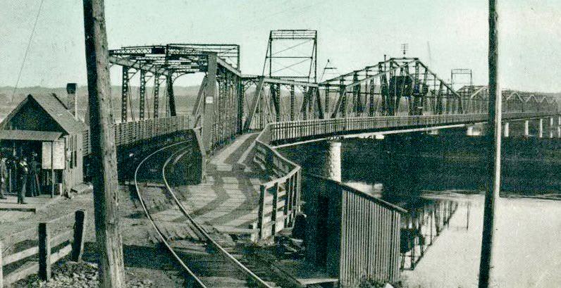

be less than two hundred and fifty feet, if the proper location of the draw over the channel will admit spans of this width between it and the shore, and said spans shall not be less than thirty feet above low-water mark and not less than ten above extreme high-water mark, measuring to the bottom chord of the bridge; and the piers of said bridge shall be parallel with the current of the river where said bridge may be erected.”
The corporation was authorized, “with the consent of the board of supervisors of the county in which the bridge was to be partly located, to construct a railroad bridge with suitable highways and footways for teams and foot passengers, and to charge toll therefor.” In October 1886, Illinois incorporated the Mississippi River Railroad and Toll Bridge Company with power to construct, maintain and operate the bridge. In December 1886, the Fort Madison and Illinois Railway and Bridge Company assigned to the Illinois corporation all its rights, property, and franchise. The bridge would link Fort Madison, Iowa, with Niota, Illinois. Maltby in his article on Mississippi River bridges wrote.
“The river valley at this point is about two miles wide with rather low banks on either side. The low water width was about 1,350 feet, with a high-water width of at least 4,000 feet. No rock was found in the river bed, but on the Iowa side blue clay was found and also formed the bed of the river to about the position occupied by pier No. 4. Beyond that it seems to dip rapidly and is covered with sand…
The structure consists, commencing on the Iowa side, first, of an abutment, then two 150-foot spans, then a draw span 400.5 feet long over all, then a span 274.5 feet long, then four spans 237.5 feet long, center to center of piers, then a trestle approach.
The bridge rests on masonry piers throughout, built of stone from Stone City, Iowa…The abutment on the Iowa side rests on piles driven into the clay and cut off about 8 feet below water and about 4 feet below the surface of the clay…The piles are surmounted by a timber grillage 4 feet 3 inches in thickness, which also formed the bottom of open caissons used in laying up the masonry. The draw pier is circular and the caisson was built in the same form… The superstructure was built by the Union Bridge Co. The trusses are for single track and are single intersection, with long panels and inclined top chords. They are designed for a loading of two 86-ton engines followed by a train load of 3,000 lbs. to the foot; this loading was increased 25 per cent. for the flooring system. No increase was allowed for the loading of the wagon road, as it was
thought impossible to bring a concentrated load on the wagon way at the same time the bridge was occupied by a train; the unit stresses allowed in the members were, however, reduced 10 per cent to allow for this increased load. The wagon road is 8 feet wide and is carried on brackets outside the trusses on each side.”
The foundations of wooden piles were built by Sooysmith & Son of New York with masonry piers and abutments. The superstructure was fabricated and erected by the Union Bridge Company, also of New York. The Union Bridge Company was formed by a merger of the Delaware Bridge Company, the Central Bridge Company of Buffalo (formerly Kellogg Bridge Company), and the Kellogg & Maurice Company of Athens, Pennsylvania. Its two leading engineers were Charles Macdonald and T. C. Clarke, the engineer of the Quincy Bridge. Construction on the bridge started on March 16, 1887, and the swing span was first swung on November 11, 1887. A local newspaper reported on December 8 that the tracks over the bridge were laid on the previous day. Another wrote on December 9, “The city was wild with enthusiasm. Bells were rung and whistles blew. A large excursion train was run to the Illinois side, and Mayor Hamilton made a brief address congratulating the citizens. The first through train from Chicago will arrive to-morrow of next day.”
The road was turned over to the operating department on December 15, 1887, and was in full operation on January 1, 1888. What Chanute, the Union Bridge Company, and Sooysmith & Sons had done was build a wrought iron bridge with six fixed spans plus a 400-feet swing span for a total length of 1,925 feet with 935 feet-long trestle approach for $580,000 in the short time of 10 months. The fixed spans were a form of Pratt truss with curved upper chords. The swing span of 400 feet, more than the 360 feet called for, was similar to the earlier Louisiana Bridge. The spans were replaced in 1927 by a double deck bridge with trains on the lower deck and automobiles on the upper deck, due to a large increase of loading. Its swing span was the longest double deck bridge in the world. ■
Dr. Frank Griggs, Dist.M. ASCE, specializes in the restoration of historic bridges, having restored many 19th Century cast and wrought iron bridges. He is now an Independent Consulting Engineer (fgriggsjr@verizon.net).
Recasting structural design as a machine-learned inverse problem.
By Danny Smyl, Ph.D, PE

In the theater of structural engineering, design is naturally an inverse puzzle: you specify your performance wish list—like load capacity, serviceability targets, and budget constraints—and then pinpoint the geometry and materials that deliver the goods. Ironically, common practice does the reverse: propose a concept, poke at it until it behaves, and repeat until it finally checks all the boxes. While this forward-thinking routine has served the field for ages, it feels a bit like baking a cookie without choosing the flavor first. Recognizing design as inherently an inverse problem opens a door to more direct and efficient problem-solving.
Framing a design project as an inverse operation from the start brings welcome clarity to juggling multiple goals. Instead of grasping at an initial shape, you begin by articulating must-have targets—strength, allowable deflections, cost ceilings, etc.—and systematically derive a design that meets them. This approach streamlines decisions by cutting out repetitive guess-and-adjust cycles, leaving engineers freer to focus on strategic thinking rather than rehashing calculations. In short, it’s a more deliberate way of hitting the design bull’s-eye.
Enter machine learning: taking the inverse paradigm to the next level. These algorithms excel at searching vast design spaces far faster (and arguably less grumpily) than humans. Through injecting your project’s performance criteria, you enable a system that can ideally serve up near-optimal configurations—or even unearth innovative facets you might’ve missed. The real special sauce, though, is how quickly it can pivot if circumstances shift, such as changes in budget or new sustainability targets. This doesn’t replace engineering expertise; it amplifies it, turning tedious number-crunching into an efficient, data-driven (and ideally, physics-informed) partnership. Think: an engineer’s elf.
Machine learning also democratizes access to advanced design and optimization capabilities. In the past, such iterative problem-solving often required extensive computational resources and specialized expertise. Today, with accessible machine learning frameworks and cloud computing, engineers and designers across disciplines can harness its power without needing to master complex algorithms or data science. This creates a more level playing field where creativity and innovation take center stage, supported by cutting-edge tools
that once felt out of reach.
Additionally, these systems shine in collaborative environments, where diverse teams need to align on competing priorities. Machine learning’s ability to incorporate multiple objectives—whether they involve performance, cost, aesthetics, or sustainability—enables stakeholders to explore trade-offs transparently. This fosters a more informed decision-making process and helps to build consensus faster, reducing bottlenecks and accelerating timelines. It’s not just a tool for optimization; it’s a bridge between vision and reality. That said, moving straight to machine-learned final designs without a careful review process can feel a bit like the plot of The Terminator : bold, futuristic ideas with potential, but leaving everyone wondering if they’re quite ready to stand the test of scrutiny. A more balanced approach might be to leverage machine learning in the conceptual phase, letting it generate innovative possibilities while experienced teams refine and validate the results. Like the T-800 working under human guidance, machine learning thrives as a powerful ally, contributing creativity and efficiency while ensuring outcomes remain grounded and dependable. This way, we can harness the best of technology while maintaining the confidence that every idea is built to last.
Ultimately, it is important to mention that traditional forward methods aren’t obsolete (and won’t be)—centuries of robust structures owe their existence to tried-and-true approaches. Yet blending that heritage with the inverse perspective offers a more direct route to top-tier outcomes, potentially unveiling fresh solutions you wouldn’t find by inching forward from scratch. By embracing the essence of inverse design—defining the endpoints first and letting intelligent tools map the route—you cut down on detours and keep your designs lean, resilient, and future-ready. It’s a shift in mindset that just might usher in a wave of structural ingenuity. ■
