WOOD CONNECTIONS Reviving a WWII Airship Hangar INSIDE: Mass Timber in Affordable Housing 22 Wood-Framed Type III Construction 14 Investigating a Log Building Collapse 27 Saving a Historic Terra Cotta Arch Floor 37
MAY 2024 NCSEA | CASE | SEI
STRUCTURE
INNOVATE FREELY


CAST CONNEX ® custom steel castings allow for projects previously unachievable by conventional fabrication methods.
Innovative steel castings reduce construction time and costs, and provide enhanced connection strength, ductility, and fatigue resistance.

Freeform castings allow for flexible building and bridge geometry, enabling architects and engineers to realize their design ambitions.
Custom Cast Solutions simplify complex and repetitive connections and are ideal for architecturally exposed applications.


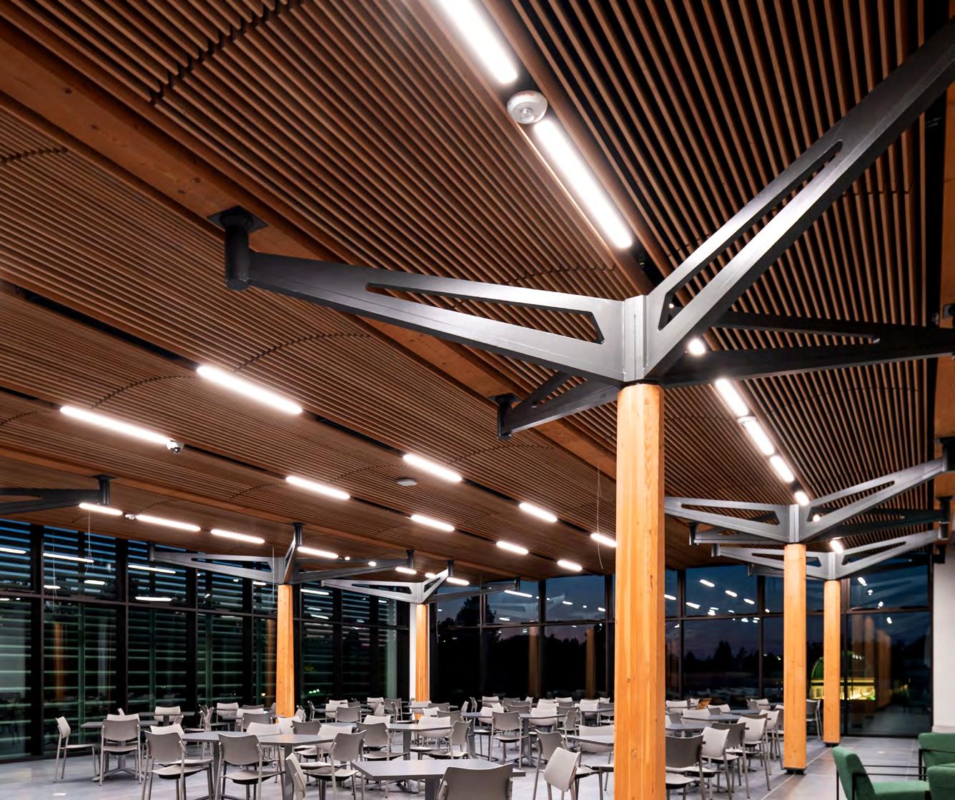
Architect: Perkins&Will
Structural Engineer: Fast+Epp
Steel Fabricator: George Third & Son Ltd. Photography by Brett Ryan Photography
www.castconnex.com info@castconnex.com | 1-888-681-8786 UNIVERSITY OF VICTORIA, STUDENT HOUSING & DINING, BC
CUSTOM CASTING
Modular Custom Steel Castings.
Scan this QR-Code to see the steel casting in action.
Assembled Modular Custom Steel Casting

EDITORIAL BOARD
Chair John A. Dal Pino, S.E. Claremont Engineers Inc., Oakland, CA chair@STRUCTUREmag.org
Marshall Carman, P.E., S.E. Schaefer, Cincinnati, Ohio
Erin Conaway, P.E. AISC, Littleton, CO
Linda M. Kaplan, P.E. Pennoni, Pittsburgh, PA
Nicholas Lang, P.E. Vice President Engineering & Advocacy, Masonry Concrete Masonry and Hardscapes Association (CMHA)
Jessica Mandrick, P.E., S.E., LEED AP Gilsanz Murray Steficek, LLP, New York, NY
Jason McCool, P.E. Robbins Engineering Consultants, Little Rock, AR
Brian W. Miller
Cast Connex Corporation, Davis, CA
Evans Mountzouris, P.E. Retired, Milford, CT
Kenneth Ogorzalek, P.E., S.E. KPFF Consulting Engineers, San Francisco, CA (WI)
John “Buddy” Showalter, P.E. International Code Council, Washington, DC
Eytan Solomon, P.E., LEED AP Silman, New York, NY
Jeannette M. Torrents, P.E., S.E., LEED AP JVA, Inc., Boulder, CO
EDITORIAL STAFF
Executive Editor Alfred Spada aspada@ncsea.com
Managing Editor Shannon Wetzel swetzel@structuremag.org
Production production@structuremag.org
MARKETING & ADVERTISING SALES
Director for Sales, Marketing & Business Development
Monica Shripka Tel: 773-974-6561 monica.shripka@STRUCTUREmag.org
3 MAY 2024 ADVERTISER index Please support these advertisers Anthony/Canfor. 21 ASDIP Structural Software 3 Cast Connex Inside Front Cover Computers & Structures, Inc. Back Cover CTS Cement Manufacturing Corp. 7 Enercalc 8 JLG Industries 42 MiTek 13 Nucor 6 Simpson Strong-Tie 4 Strongwell 12
® CIRCULATION
STRUCTURE
subscriptions@structuremag.org
STRUCTURE ® magazine (ISSN 1536 4283) is published monthly by The National Council of Structural Engineers Associations (a nonprofit Association), 20 N. Wacker Drive, Suite 750, Chicago, IL 60606 312.649.4600. Periodical postage paid at Chicago, Il, and at additional mailing offices. STRUCTURE magazine, Volume 31, Number 1, © 2024 by The National Council of Structural Engineers Associations, all rights reserved. Subscription services, back issues and subscription information tel: 312-649-4600 or write to STRUCTURE magazine Circulation, 20 N. Wacker Drive, Suite 750, Chicago, IL 60606.The publication is distributed to members of The National Council of Structural Engineers Associations through a resolution to its bylaws, and to members of CASE and SEI paid by each organization as nominal price subscription for its members as a benefit of their membership. Yearly Subscription in USA $75; $40 For Students; Canada $90; $60 for Canadian Students; Foreign $135, $90 for foreign students. Editorial Office: Send editorial mail to: STRUCTURE magazine, Attn: Editorial, 20 N. Wacker Drive, Suite 750, Chicago, IL 60606. POSTMASTER: Send Address changes to STRUCTURE magazine, 20 N. Wacker Drive, Suite 750, Chicago, IL 60606. STRUCTURE is a registered trademark of the National Council of Structural Engineers Associations (NCSEA). Articles may not be reproduced in whole or in part without the written permission of the publisher. Digital Issue
Only at STRUCTUREmag.org May 2024 ADVERTISEMENT–For Advertiser Information, visit STRUCTUREmag.org
Available
Thousands of solutions. One proven partner.


Simpson Strong-Tie provides comprehensive product solutions for commercial institutional construction. Whether you’re building an educational facility, healthcare center or public office, you can rely on a full array of products that are assembly-tested and proven for strength and versatility. From cold-formed steel and structural steel to adhesive and mechanical anchors, code-listed connectors and fastening systems, we have what you need to build safer, stronger structures. Our nationwide distribution network ensures product availability and timely jobsite delivery. Along the way, our expert field, technical and sales support teams are always ready to assist you. With Simpson Strong-Tie as your partner, you have a total solution designed to elevate performance. To learn more about our complete solutions for institutional construction, visit strongtie.com/institutional or call (800) 999-5099.
Yield-Link® Moment Connection Titen HD® Heavy-Duty Screw Anchor SET-3G™ High-Strength Epoxy Adhesive Institutional Solutions | Products, Software and Service for Smarter Building
© 2024 Simpson Strong-Tie Company Inc. M-CC-INSTITUTN24 G3 Gas-Actuated Fastening Tool SUBH Bridging Connector
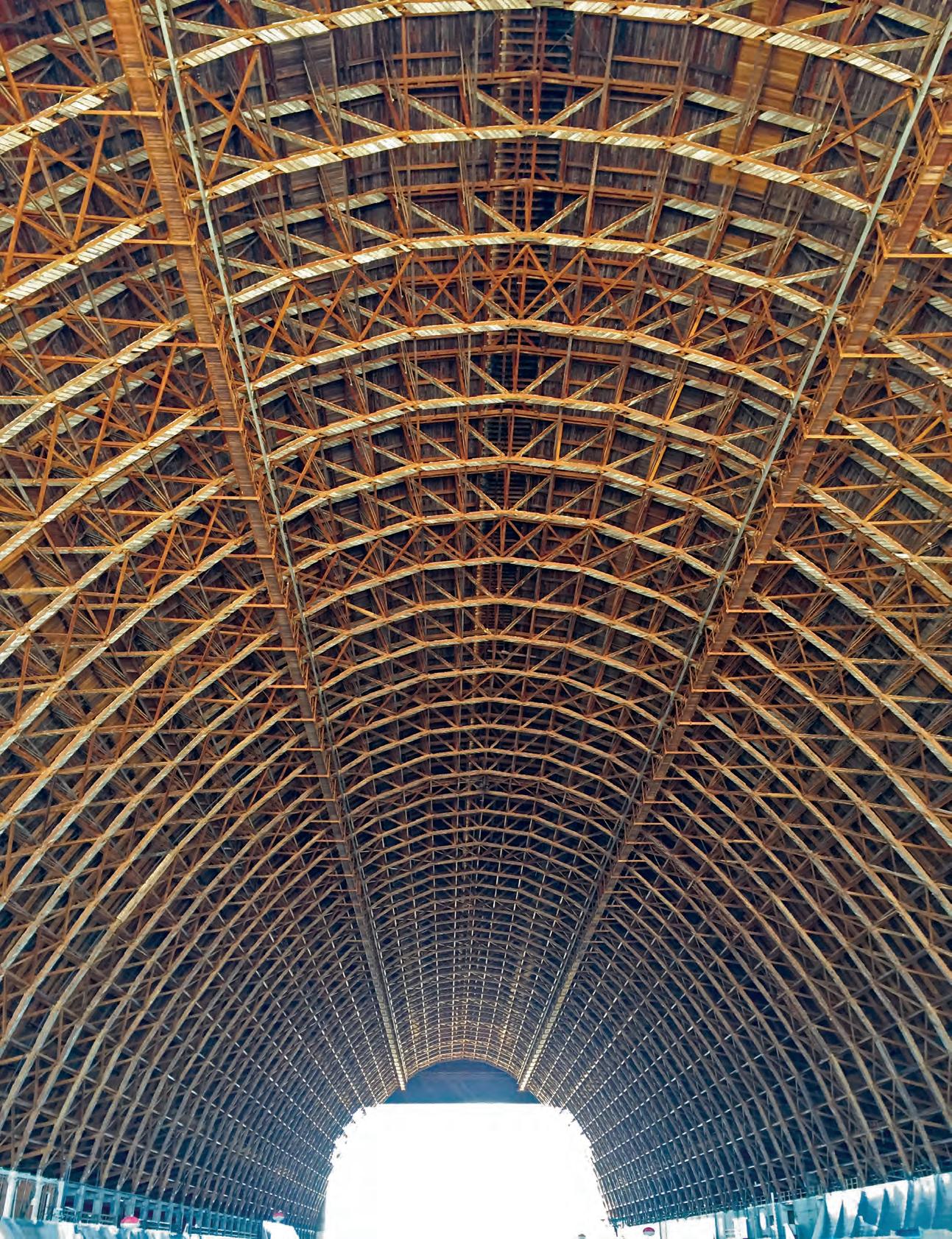
REVIVING A SAN FRANCISCO BAY AREA HISTORIC LANDMARK
By Kenneth Ogorzalek, PE, SE; Blake Dilsworth, PE, SE; and Shakhzod Takhirov, Ph.D, PE
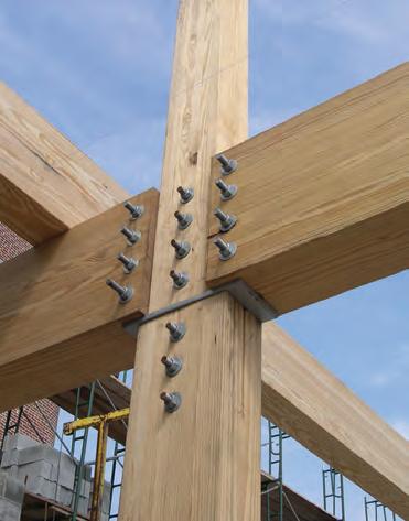
The seismic ductility and health monitoring of historic wood connections in a WWII airship hangar were enhanced using fully threaded screws.

MASS TIMBER IN AFFORDABLE

 By Peter Marxhausen, PE
Used efficiently, mass timber can be a cost-effective structural material to create sustainable, affordable housing.
MODERN MEETS HISTORIC
By Michael D. Zajac, PE, LEED AP
Innovative strengthening techniques saved the historic terra cotta flat-tile-arch floor structure of an iconic landmark.
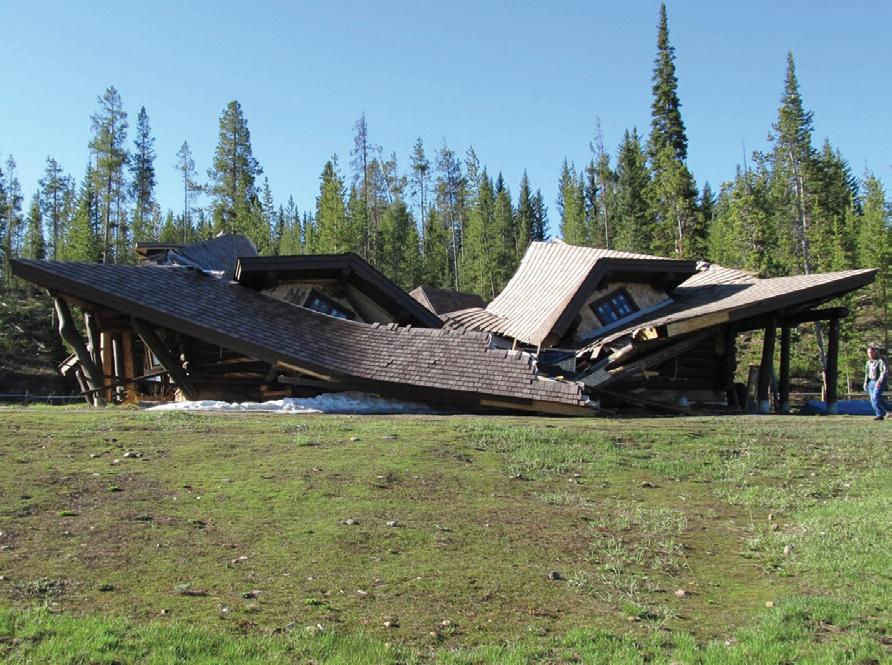
Despite adequate structural design and a less-than-design snow event, a scribed log- and sawn-lumber-framed commercial lodge structure experienced a catastrophic collapse less than two years after it was built.
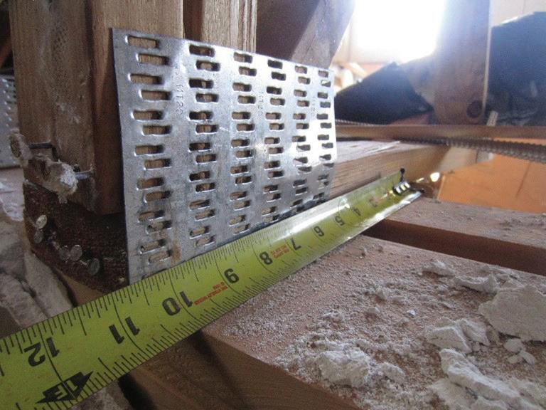
COLLAPSE: A CASE STUDY
By Scott D. Coffman, PE
The real reason for the failure of a clubhouse floor was not the dancing.
MAY 2024 5
FEATURES Contents MAY 2024
27
30
Cover Feature
37


nucor.com/madeforgood

See how high-strength steel is enabling sustainable design.
COLUMNS and DEPARTMENTS
A. Christopher Cerino, PE
Seth Duncan
 Steven G. Judd, CE, SE,
John “Buddy” Showalter, PE, and Sandra Hyde, PE
Chad S. Mitchell,
Steven G. Judd, CE, SE,
John “Buddy” Showalter, PE, and Sandra Hyde, PE
Chad S. Mitchell,
MAY 2024 7 Publication of any article, image, or advertisement in STRUCTURE® magazine does not constitute endorsement by NCSEA, CASE, SEI, the Publisher, or the Editorial Board. Authors, contributors, and advertisers retain sole responsibility for the content of their submissions. STRUCTURE magazine is not a peer-reviewed publication. Readers are encouraged to do their due diligence through personal research on topics.
In Every Issue 3 Advertiser Index 49 Wood Guide 50 NCSEA News 52 SEI Update 54 CASE in Point 10 57 Structural Forum It Is OK to Struggle By
PE, SE 47 Structural Resilience New Solution Needed Following Flooding in Historic Office Complex Buildings By Russ Miller-Johnson, PE, SE 43 Codes Updates 2024 IBC Significant Structural Changes By
18 Structural Analysis Community Tornado Shelter Utilizing Reinforced Hollow Clay Masonry By
CBS 14 Structural Design A Practicing Engineer’s Approach to Wood-Framed Type III Construction By Jared
10 Structural Design Deferred Design By
9 Editorial The Challenge Ahead By
ADVERTISEMENT–For Advertiser Information, visit STRUCTUREmag.org
S. Hudson, PE, and Shaun M. Kreidel, SE
EDITORIAL The Challenge Ahead
By A. Christopher Cerino, PE
Thestructural engineering profession continues to face many challenges. What is fueling the pipeline of the future workforce? How do structural engineers navigate evolving environmental hazards and even more tangible physical hazards like Panamax shipping vessels near busy ports? How will the structural engineering profession remain relevant as AI continues to rapidly advance? How will structural engineers continue to push for heightened licensure laws while some jurisdictions are attempting to weaken current ones?
NCSEA’s mission centers around support of and for the practicing structural engineer, and our greatest strength is the ability to pivot as needed to address the most pressing issues. NCSEA turns 30 this year, and the challenges to the profession are not the same as in 1994. Part of the reason that NCSEA has such an amazing and active history is because we have continued to evolve with the needs of a changing profession.
While there can be great comfort in riding the wave of good times, this year, like every year, NCSEA will continue to listen to our Member Organizations (state structural engineers’ associations, or SEAs) and look to advance initiatives that support our mission and vision through today’s lens. Change can be hard and some of the challenges facing the profession come with difficult realizations and conversations. But true growth requires us to step outside of our comfort zone to stretch as individuals and together as a profession. Complacency and the phrase “this is how we always do it” are complete demotivators to me and the amazing NCSEA staff and Board of Directors that will be serving you in the upcoming year.
In our 30th year, many longer-term initiatives are starting to bear fruit. The We See Above and Beyond advocacy campaign has gone through a full cycle of its initial push and we are taking the learning from this effort and finalizing the next phase. The NCSEA Foundation, which started almost a decade ago as a small Member Organization grant program, now has a separate Board of Directors that is steering their vision around the pillars of Innovation and Research, Awareness and Advocacy, and People. And… we launched our new website! The website,
and the back-end platform and database, is a critical baseline for NCSEA to be able to provide next generational support for our initiatives, staff, committees, linked groups, and Member Organizations.
A possibly lesser-known initiative is the media spokesperson program. In the after math of the Surfside collapse, many of our Member Organizations were contacted by media outlets hunting for structural engineering sound bites. NCSEA helped to serve as a central point of connection for the requests, but it was obvious that we needed to be more coordinated and prepared for future events. NCSEA contracted a media specialist firm and at the Summit last November, 10 individuals from Member Organizations across the country graduated in the first class of media spokesperson training. Early in the morning of March 26, our new system was tested with the tragic events in Baltimore. NCSEA and our media specialist mobilized the appropriate spokespeople, coordinated a set of unified talking points, and successfully delivered almost a dozen interviews across television, radio, streaming, and written platforms. While we all are deeply saddened by the events that transpire to bring forth media interview requests, we are proud to deliver a strong and cohesive message from the structural engineering profession that advocates for use and enforcement of appropriate codes, standards, and regulations, and that brings attention to the unique knowledge and expertise of structural engineers, our critical role throughout all phases of the design and construction process, and our opportunity to contribute to the safety, sustainability, and resilience of our communities.

from the profession by classes, class sizes, instructors, and subjects that are not really
In the area of evolving hazards: Can engineers actively develop, adopt, and advocate for the use of the Future Conditions chapter of ASCE/SEI 7 that is being developed? Can we continue to inform our members about the evolving standard of care with respect to climate and provide interim design recommendations while standards are being developed? Can we continue to refine hazard performance expectations and promote concepts of functional recovery and community resilience over just basic life safety? Can we work with regulators to draft a uniform vessel impact, pier protection, and operating procedure guidance for our critical ports that support megashipping fleets?
With respect to AI: Can we provide clear and truthful guidance to our members on the risks and opportunities to the profession? Can we provide education that explains the over-saturated buzzwords that appear throughout the media? Can we provide targeted education for individuals and firms of all sizes on how to effectively navigate entering or advancing your use of AI?
In terms of licensure: Can structural engineering media attention surrounding events fuel positive legislative change? Can the joint leadership of CASE, NCSEA, and SEI provide a strong, unified voice in state and national arenas advocating for the advancement of public safety that comes through adequate licensing and continuing education requirements?
So how will NCSEA address the current challenges in the profession?
For the question of pipeline: Can we continue to exponentially grow diversity and other scholarships for college students in need and host them at the Summit? Can we support a national “Pathways” to the SE profession program or partner with Member Organization to grow theirs? Can we challenge universities and the antiquated ABET structural engineering education model where many potential engineers are “weeded out” and driven
Structural engineers are uniquely suited to be expert leaders for owners, agencies, and developers on multi-disciplinary teams throughout the entire design, construction, and project lifecycle. We must continue to challenge our current daily practice to secure this role and to inspire and elevate the future of the profession. ■
STRUCTURE magazine MAY 2024 9
A. Christopher Cerino, PE, F.SEI, DBIA, is Vice President and Technical Director of structural engineering, urbanism and planning for STV. He is also President of the NCSEA Board of Directors.
structural DESIGN
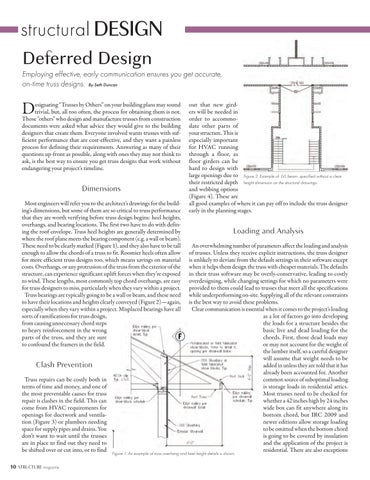
Deferred Design
Employing effective, early communication ensures you get accurate, on-time truss designs. By Seth Duncan
Designating “Trusses by Others” on your building plans may sound trivial, but, all too often, the process for obtaining them is not. Those "others" who design and manufacture trusses from construction documents were asked what advice they would give to the building designers that create them. Everyone involved wants trusses with sufficient performance that are cost-effective, and they want a painless process for defining their requirements. Answering as many of their questions up-front as possible, along with ones they may not think to ask, is the best way to ensure you get truss designs that work without endangering your project’s timeline.
Dimensions
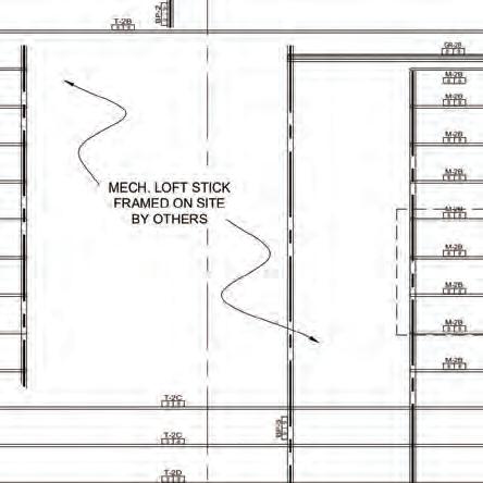
Most engineers will refer you to the architect’s drawings for the building’s dimensions, but some of them are so critical to truss performance that they are worth verifying before truss design begins: heel heights, overhangs, and bearing locations. The first two have to do with defining the roof envelope. Truss heel heights are generally determined by where the roof plane meets the bearing component (e.g. a wall or beam). These need to be clearly marked (Figure 1), and they also have to be tall enough to allow the chords of a truss to fit. Roomier heels often allow for more efficient truss designs too, which means savings on material costs. Overhangs, or any protrusion of the truss from the exterior of the structure, can experience significant uplift forces when they’re exposed to wind. These lengths, most commonly top chord overhangs, are easy for truss designers to miss, particularly when they vary within a project. Truss bearings are typically going to be a wall or beam, and these need to have their locations and heights clearly conveyed (Figure 2)—again, especially when they vary within a project. Misplaced bearings have all sorts of ramifications for truss design, from causing unnecessary chord steps to heavy reinforcement in the wrong parts of the truss, and they are sure to confound the framers in the field.
Clash Prevention
Truss repairs can be costly both in terms of time and money, and one of the most preventable causes for truss repair is clashes in the field. This can come from HVAC requirements for openings for ductwork and ventilation (Figure 3) or plumbers needing space for supply pipes and drains. You don’t want to wait until the trusses are in place to find out they need to be shifted over or cut into, or to find
out that new girders will be needed in order to accommodate other parts of your structure. This is especially important for HVAC running through a floor, as floor girders can be hard to design with large openings due to their restricted depth and webbing options (Figure 4). These are all good examples of where it can pay off to include the truss designer early in the planning stages.
Loading and Analysis
An overwhelming number of parameters affect the loading and analysis of trusses. Unless they receive explicit instructions, the truss designer is unlikely to deviate from the default settings in their software except when it helps them design the truss with cheaper materials. The defaults in their truss software may be overly-conservative, leading to costly overdesigning, while changing settings for which no parameters were provided to them could lead to trusses that meet all the specifications while underperforming on-site. Supplying all of the relevant constraints is the best way to avoid these problems.
Clear communication is essential when it comes to the project’s loading as a lot of factors go into developing the loads for a structure besides the basic live and dead loading for the chords. First, those dead loads may or may not account for the weight of the lumber itself, so a careful designer will assume that weight needs to be added in unless they are told that it has already been accounted for. Another common source of suboptimal loading is storage loads in residential attics. Most trusses need to be checked for whether a 42 inches high by 24 inches wide box can fit anywhere along its bottom chord, but IRC 2009 and newer editions allow storage loading to be omitted when the bottom chord is going to be covered by insulation and the application of the project is residential. There are also exceptions
STRUCTURE magazine 10
Figure 2. Example of LVL beam specified without a clear height dimension on the structural drawings.
Figure 1. An example of truss overhang and heel height details is shown.
in some codes for structures without an attic access of 20 inches x 30 inches. For wind loading, you may want to specify whether to use the Envelope or Directional procedure. The envelope procedure is a newer method that can be used for “low-rise” buildings with a mean roof height less than or equal to 60 feet and is typically the more accurate of the two methods for those structures.
Snow loading can be significantly affected by the conditions in which the structure exists. The terrain and exposure categories describe to what extent wind will help prevent snow buildup on the roof, the thermal factor takes into account whether or not the structure experiences sustained freezing temperatures below its roof in winter, and estimates of snow accumulation can be dramatically affected by the “slipperiness” of the roof as well as how well-ventilated it is.
Commercial structures in particular are more likely to have things like towers or other structures that require bracing to be attached to the roof (Figure 5). Experienced truss designers will notice items like this and either request clarification or make some assumptions.
Perhaps the most important inputs the building designer can provide into the truss analysis are the deflection limits. The building code has standards for this, of course, but you may find there are cases where the code allows for long-span trusses to deflect up to 2 inches, which can lead to problems like ceiling cracks. ANSI/TPI 1-2022 Table 7.6-1 has deflection limits that account for long-term deflection. Using more stringent deflection criteria and/or compensating for bottom chord deflection by specifying sufficient camber, or upward curvature, of the bottom chords may be necessary, especially for long, unsupported spans. The stakes are even higher for floor trusses, where certain flooring materials like stone, concrete, and tile are especially prone to cracking.
Material Cost and Design Time
There are many ways that insufficient planning up-front can lead to unnecessarily expensive trusses. One of the most common is the case of locating girders, or the trusses, that will support sets of trusses. Here are some rules of thumb: first, place a girder at a right angle to whatever it will be carrying whenever possible. That means to avoid placing girders on valley lines and at an angle relative to the wall. Angled truss-truss
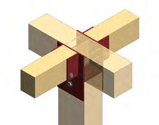
connections are significantly more expensive than perpendicular ones, so use the latter as much as possible. Another is to minimize the hip girder’s setback distance from the wall, ideally about 6 feet or less in residential construction. Again, the reason is to minimize the cost of the trussto-truss connections, and, in many cases allowing for nailed connections in place of an expensive hanger.
On commercial projects, seeing if a girder is a viable option ahead of time may save money and frustration down the road. When loads are high, sometimes it is more cost effective to use a LVL or steel beam to support an area of the roof or floor as opposed to a massive girder. The last thing you want is to specify “Truss Girder by Others” only to find out when the trusses are being designed that a girder fails in that area. Having to change the architectural design of a building to accommodate an unexpected beam or column is something that can severely slow a project down.
Another way to reduce material costs is to keep the building as symmetrical and consistent as possible. The more times you can reuse a truss design, the less time designers have to spend creating truss designs and the more efficiently the trusses can be manufactured. The more you can avoid variations in wall height, roof pitches, etc., the more economical the trusses are going to be. It’s also helpful to consider allowing for trusses to have a consistent, even spacing. This convention comes from trussed roofs with plywood sheathing since plywood is sold in 8-foot sheets. Committing to a multiple of two for your truss spacing can significantly reduce framing time and material costs.
For any project, looking at the “worst case” truss design from the whole layout to find out if a design will work ahead of time is a good way to avoid costly redesigns down the road. The sooner you find what it takes to get that truss to work, the sooner you can update your cost estimates accordingly or begin the redesign process before too much work must be redone. Making the entire floor deeper or raising the heel height to improve truss performance is much easier at the beginning of the design process than at the end.
Connections and Bracing
Once truss design has been completed, there are still some trussrelated items for which the structural engineer is responsible. The first
MAY 2024 11
Figure 3. Trusses would have been more cost-effective for supporting this platform for HVAC equipment, but not enough was known about where to locate the openings in the roof at the time of truss design.
Figure 4. This example shows a heavily-reinforced floor girder with an opening for HVAC.

is the plan for attaching trusses to their bearings. The finalized truss designs will include the reactions at each bearing, but a plan for attaching them to the building does not come with the trusses. In some cases, the earlier you consider this the better—you don’t want to wait until the trusses have been fully designed to realize there isn’t enough heel height to tie the trusses to the walls in a high-wind area.
The other remaining work is coming up with a bracing plan. Continuous lateral bracing is needed to prevent truss buckling under construction loads. Also, some individual truss designs are going to require permanent bracing, and it is the building designer’s responsibility to determine how to attach that bracing to the trusses as well as how to tie that bracing into the rest of the building.

Conclusion
The more complex the project, the more critical effective communication becomes, and the earlier that communication begins, the better. As Kirk Grundahl put it in a STRUCTURE magazine article in March 2020:
“One solution that works well is Building Designers and General Contractors (GCs) who commit to work with a specific CM [component manufacturer] early in the project life cycle. Communication and collaboration at the design development stage of any project solve many of the problems that typically present themselves during a deferred submission review and revision process.”
The increasing popularity of the DesignBuild model means that building designers need finished truss designs much earlier in the submittal process, but since truss designers work for component manufacturers, getting truss designs typically means committing to use that truss manufacturer to produce the trusses up-front. The market is ripe for innovative solutions to this challenge. Whenever a truss designer does get involved, their needs are synonymous with the needs of an effective structure, and effectively anticipating those needs will lead to better outcomes for the quality and costs of all your truss projects. ■
Seth Duncan is the Director of Operations for Truss Pal, a company that provides access to wood truss design and analysis information. When he's not standing in for your buddy at the truss shop who helps answer your truss questions, Duncan likes spending time with his family outdoors. Connect with him on LinkedIn or visit trusspal.com.
STRUCTURE magazine 12
ADVERTISEMENT–For Advertiser Information, visit STRUCTUREmag.org
Figure 5. The towers in this restaurant roof have unique challenges for bracing, wind resistance, and snow drifting.
Calculations You Can Truss(t)
Introducing the new MiTek Truss Validator. Instantly confirm floor truss viability.

24’ span

16” depth


24” spacing

Lumber species


PROJECT
CHECK YOUR
structural DESIGN
A Practicing Engineer’s Approach to Wood-Framed Type III Construction
Design considerations and common detailing strategies for Wood-Framed Type III construction are discussed.
By Jared S. Hudson, PE, and Shaun M. Kreidel, SE
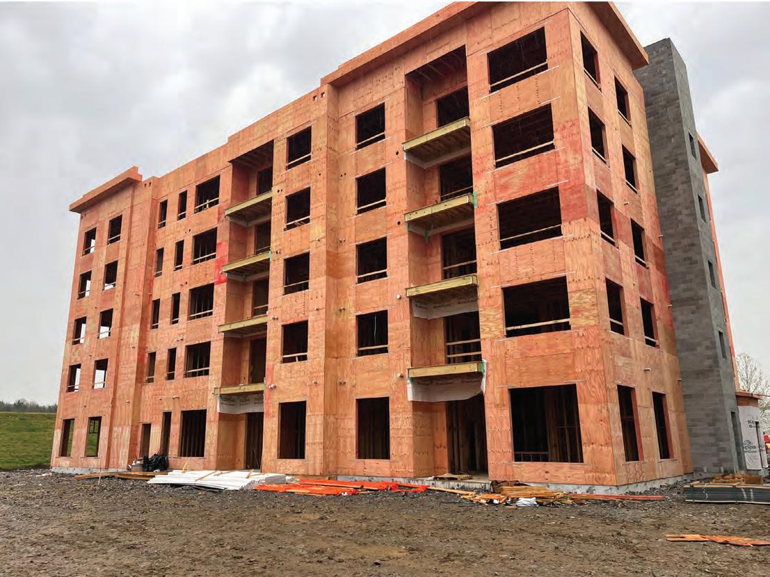
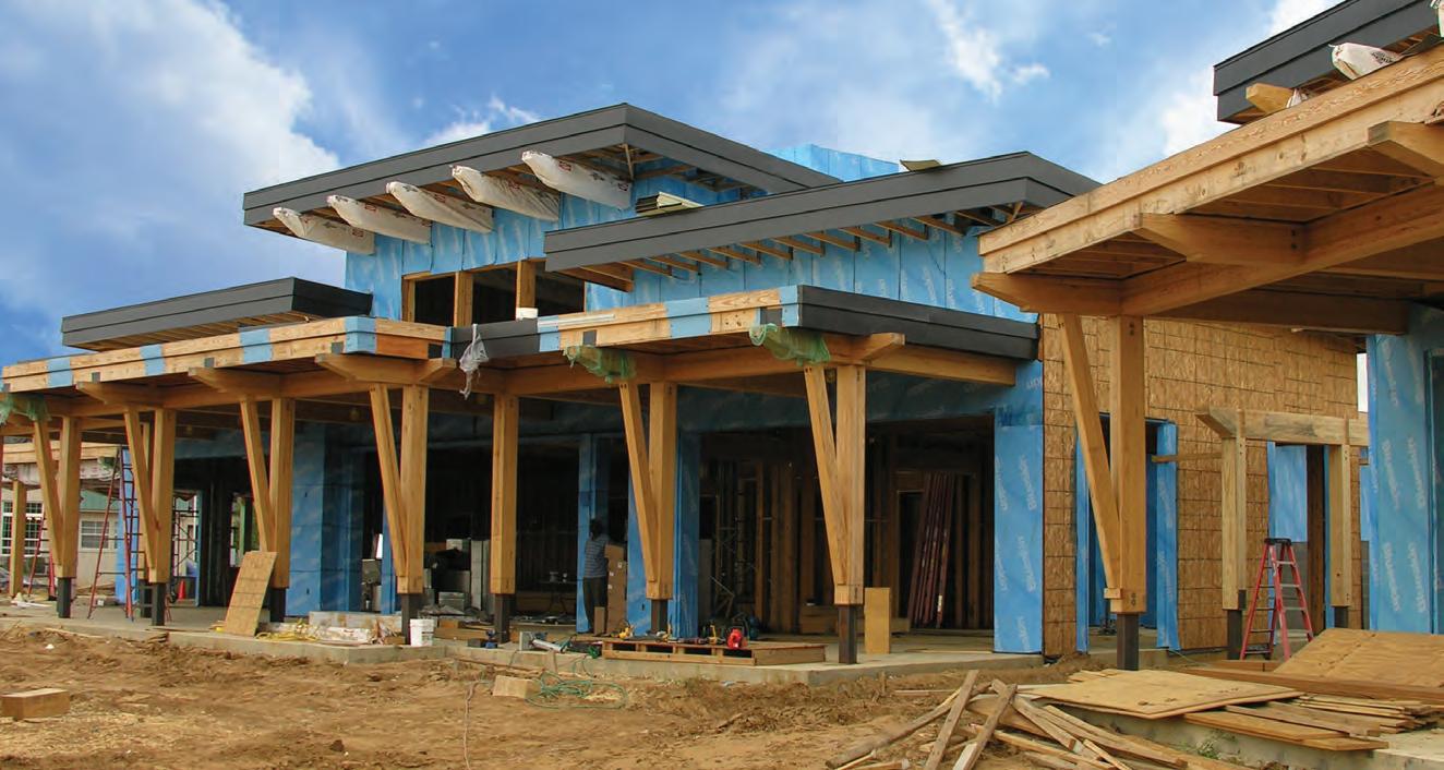
Light frame wood construction is often a desired construction method for low-rise multifamily structures due to readily available labor and materials, speed of construction, sustainability, and relatively low construction costs. A Type V construction classification as defined by the International Building Code (IBC) is commonplace for these structures; however, this construction type is limited to four stories of stacking wood construction. A Type III construction classification allows conventional wood-framed structures to include an additional level, bringing the allowable height to five stories above grade; see Figure 1 for an example of this type of construction. This construction type may be attractive to developers looking to maximize the occupiable square footage of a defined footprint while taking advantage of the many benefits that come with light-frame wood construction. To facilitate a Type III classification, unique structural and architectural detailing is
needed to maintain the strength, stability, and serviceability of the wood-framed structure, as well as to address the applicable fire design requirements. These details are multidisciplinary in nature and require a high level of collaboration between the structural engineer, architect, and builder/developer to ensure that the project meets the owner’s expectations and the building code requirements of the Authority Having Jurisdiction (AHJ).
Depending on the requirements of a given project, practicing engineers may need to investigate certain design aspects that become critical when meeting the requirements of Type III construction. These design considerations include material requirements, fireresistance rating requirements, the importance of designing for wood shrinkage, and structural detailing strategies to accommodate fire-resistance ratings at the intersection of the floor/roof assemblies and exterior wall assemblies.
STRUCTURE 14
Figure 1: This building in Nashville, Tennessee, is an example of Type III construction. Photo courtesy of Jared S. Hudson.
Material Requirements
While construction Types I, II, and III all require the use of non-combustible materials at exterior walls, the IBC recognizes the use of fire-retardant-treated (FRT) sawn lumber and FRT wood structural panel (WSP) sheathing as acceptable materials to satisfy the requirement under Type III construction. Practicing engineers should account for FRT lumber and FRT sheathing strength reduction factors due to the treatment process. The strength reduction factors are manufacturer-specific, thus coordination with the architect and builder/developer is recommended if the intended product is unknown.
FRT treatment process results in sheathing strength reduction factors which can decrease both the allowable spans and the lateral strength/ stiffness of diaphragms or shear walls. FRT lumber treatment process also affects the structural properties of sawn lumber; the designer may need to augment the wall/header designs to mitigate these effects. Table 1 illustrates the strength reduction factors from two manufacturers of FRT sawn lumber. Assumed in-service temperature of the lumber is an important consideration that may cause variation in structural property values between manufacturers. High in-service temperatures of more than 100 degrees Fahrenheit will correspond to a greater reduction in strength and stiffness when coupled with fire retardant treatment. The engineer should also account for any wood incising reduction factors that might be needed to treat the lumber and consider using lumber that does not require incising to mitigate the amount of strength reduction. All minimum assumed FRT properties should be listed as design assumptions in the contract drawings to ensure that suitable lumber and WSP products are utilized. A designer may encounter situations where spans or loads require structural properties beyond what FRT lumber alone can provide. At this time, there are no fire-treated engineered wood products on the market (e.g., LVL, PSL, LSL) known to the author. One strategy available to designers is to utilize a flitch beam; a composite beam that consists of FRT wood laminations bolted to a continuous steel plate. The FRT laminations of the composite assembly will maintain the non-combustibility requirement; however, special attention to detailing to adequately conceal the heads of the bolts of the flitch beam assembly will be required. The designer should also consider
FRT Strength Reduction Factors
Modulus
Compression
Perpendicular to
0.950-0.960 0.977-1.000
the expansion of the longitudinal steel due to elevated service temperatures for longer-spanning flitch beams. Another strategy that the designer can employ is the use of rolled steel framing members within the exterior wall. These members may require additional fire protection along with meeting the noncombustible requirements of the code; the project architect should be consulted for additional fire protection requirements of these members.
Fire Rating Requirements
Type III construction requires that exterior loadbearing walls satisfy a 2-hour fire-resistance rating (FRR). If exterior walls can be classified as non-load bearing, the FRR can be reduced to 1-hour for certain occupancies. A 2-hour FRR is usually accomplished by having two interior layers of gypsum board. Over the full perimeter of the structure, the added cost of an additional layer of gypsum board can be substantial. A common industry interpretation of a non-load bearing exterior wall is one that does not support anything but its self-weight and the self-weight of the walls above. The structural designer can strategically run the framing parallel or introduce girder members parallel with the exterior wall to avoid a load bearing situation. In doing so, a FRR of 1 hour can be utilized and thus an extra layer of interior gypsum board can be avoided. This approach and interpretation should be discussed with the project architect and the AHJ during design to ensure compliance with the local building code.
The vertical continuity requirements of the rated exterior wall assembly have been a hotly debated topic between jurisdictions and design professionals, but the requirements have finally been clarified in the 2024 IBC. According to Section 705.6 of the 2024 IBC, the exterior wall FRR shall extend continuously from the top of the foundation/ floor system below to the underside of the roof/floor sheathing above. However, if the fire separation distance (as defined in the IBC) is greater than 10 feet, the exterior wall FRR is permitted to terminate at the underside of a ceiling (floor or roof) assembly having an equal or greater FRR than the exterior wall. Detailing at the floor levels and the roof level will need to conform to these requirements. Some commonly used detailing strategies that meet these criteria are presented later in this article.
Wood Shrinkage
With taller wood structures, the consideration of expected wood shrinkage becomes critical. Failure to account for the natural shrinkage of the wood structure may be problematic to the performance and serviceability of both in-wall utilities such as rigid pipes, and brittle veneers such as brick. Lateral ties for brittle veneers shall be designed to accommodate the vertical movement anticipated for a given structure. Expansion of veneers such as brick, which absorb moisture and expand over time, should also be accounted for in the vertical allowance of the ties.
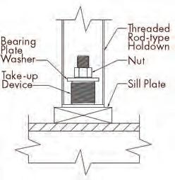
Wood shrinkage can also have a large impact on calculated shear wall deflections. Mechanical hold-down deformation is a component of the shear wall deflection equation. At shear walls where hold-downs are utilized, the amount of wood shrinkage between levels is additive to the deformation (elongation) of the hold-down device. To eliminate this effect, the building designer can utilize a take-up device as part
MAY 2024 15
Property Manufacturer A Manufacturer B Bending Stress 0.800-0.970 0.740-0.972 Tension Parallel to Grain 0.800-0.950 0.625-0.874
Parallel to Grain 0.940-1.000 0.935
Shear
Compression
Horizontal
0.920-0.960 0.838-0.985
Elasticity
of
Grain
0.900 0.900
0.950 Not Reported Fasteners
Table 1. FRT Strength Reduction Factor Comparison
Figure 2: Shown is an Illustration of a holddown take-up device. Detail courtesy of Jared S. Hudson.

of the hold-down assembly to restore hold-down tautness and thus eliminate this source of added shear wall deflection.
Floor Assembly—Exterior Wall Assembly Detailing Strategies
The following subsections present a few common methods for detailing the floor assembly intersection with the exterior wall assembly for this type of construction. These methods have respective advantages and disadvantages which the designer and design team will need to weigh while considering the topics discussed above.
The common thread between all the detailing strategies is maintaining the 2-hour FRR assembly at the wall intersection with the floor system. The chosen details may affect structural member lengths (e.g., wall studs and roof/floor members), bearing conditions, hardware requirements, and blocking/fire caulking requirements. These different detailing approaches will also yield different overall expected wood shrinkage values. The shrinkage of wood parallel to grain (e.g., vertical wall studs) and pre-manufactured wood floor components is negligible when compared to the shrinkage of wood perpendicular to grain (e.g., flat plates). Limiting the total number of flat plates in the exterior wall assembly will therefore minimize the overall expected shrinkage in these structures. For structures particularly sensitive to this shrinkage, it is recommended that the designer lists the anticipated shrinkage values in the construction drawings so that the other members of the design team can coordinate their components and assemblies.
The FRT requirements of the floor system bearing components has been a topic of debate in previous code cycles. The 2024 edition of the IBC, Section 705.7.1, has clarified that the elements of the floor system bearing on the exterior walls and supporting gravity loads from the exterior wall above shall be in accordance with the requirements for interior building elements of Type III construction and are not required to be constructed of FRT lumber; however, the FRR must be extended through the floor cavity. In areas where the 2024 IBC has not been fully adopted, a discussion with the AHJ would be prudent to confirm that this added clarification will be honored by the local jurisdiction.
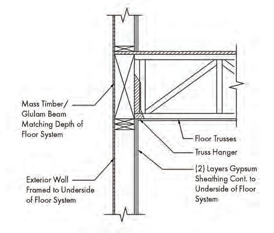
Platform Framed Construction
In multifamily construction, utilizing bottom-bearing floor systems is commonplace and often preferred as it allows for the use of consistent wall stud lengths and allows for the overlapping and interconnection of wall double top plates. Traditional platform frame construction with floor trusses relies on a continuous ribbon board, which distributes the loads above to the truss verticals and supports the floor sheathing edge. To meet the Type III FRR requirements, the individual floor truss end verticals and ribbon board would need to carry the same FRR as the wall above, which is impractical/uneconomical in most situations as the gypsum board(s) below would need to extend to the underside of the floor sheathing and fire caulking would need to be applied at each truss penetration. To achieve the required FRR, a solid rim board (glulam/mass timber) occupying the full width of the exterior wall assembly can be utilized per Figure 3. The FRR is achieved through the mass and char capabilities of the rim board which would need to be calculated per the provisions in Chapter 16 of the National Design Specification (NDS) for Wood Construction (or the newly released 2024 Fire Design Specification [FDS] for Wood Construction published by the American Wood Council).
The advantages of this detailing approach are consistent wall plate heights across the structure and minimized shrinkage via engineered lumber for the full depth of the floor system. Disadvantages are the added costs associated with the rim board along the full perimeter of the structure and the floor system connection hardware to the rim board, sequencing issues with the placement of the rim board prior to the floor trusses, and added difficulty in placing floor trusses due to lack of exterior bearing.
Semi-Balloon Framed Construction
Another method to frame the intersection of the floor with an exterior wall of a wood structure is using semi-balloon framed wall construction, where the floor system utilizes top chord bearing trusses to bear on the exterior wall below. Like the platform framing method, the vertical support of the exterior wall above shall have a 2-hour FRR; however, for this method, the gypsum board from below can
STRUCTURE magazine 16
Figure 3. To achieve the floor system FRR, a solid rim board (glulam/mass timber) occupying the full width of the exterior wall assembly can be utilized as shown in this platform framed construction detail. Detail courtesy of Jared S. Hudson.
Figure 4. In semi-balloon framed construction, fire caulking can be utilized at each of the individual truss penetrations, which are minimal compared to the penetrations in a platform framed structure, into the exterior wall. Detail courtesy of Jared S. Hudson.
more practically be extended the full height of the wall assembly due to the minimal size of the required penetrations where fire caulking would need to be utilized (Figure 4).
Advantages of this approach are reduced costs associated with truss connection hardware to the exterior wall, the ability to utilize typical rated assemblies to demonstrate the required FRR, and the use of conventional lumber to provide solid blocking to the underside of the floor sheathing above. Disadvantages are unique exterior wall plate heights relative to the interior ceiling height, limited spans of floor trusses due to the allowable capacity of top chord bearing trusses, and the addition of multiple flat plates into the exterior wall assembly which will increase overall building shrinkage.
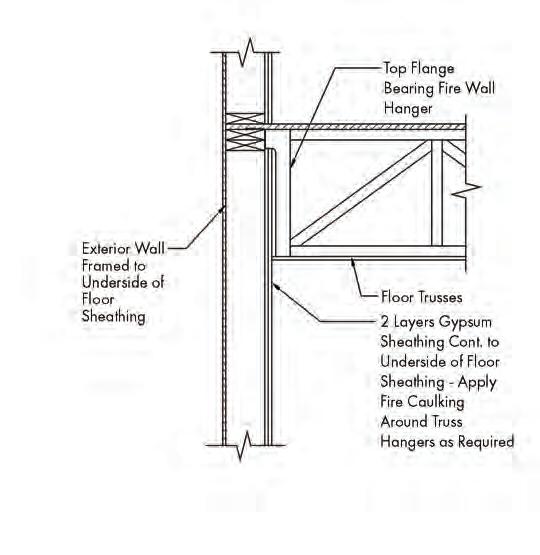
Balloon Framed Construction
The final method presented in this article is balloon-framed wall construction, where the top plate of the exterior wall below extends to the underside of the floor sheathing above per Figure 5. For this construction type, the floor trusses are supported by specialty fire wall hangers that utilize a top flange that bears on the exterior wall. Due to the popularity of this approach, these specialty hangers have evolved to allow for the interior gypsum board sheathing to be placed around the installed trusses to achieve the required exterior wall FRR.
Advantages of this approach are flexibility in the sequencing of gypsum installation, lack of additional flat plates within the exterior wall assembly thus limiting overall shrinkage, and a simplified bracing load path of the exterior walls via direct attachment to the floor sheathing. Disadvantages are the coordination of the exterior wall plate heights relative to the interior ceiling height, the potential for additional studs within the exterior wall to facilitate required hanger loads, added costs due to specialty truss connection hardware, and added difficulty in the placement of trusses due to the lack of exterior bearing.
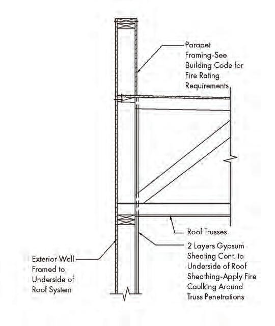
Roof Assembly—Exterior Wall Assembly Detailing Strategies
Similar to the detailing at the floor levels, the detailing strategy at the roof/exterior wall intersection can vary widely by locale and preference of the design team (Figure 6). As stated for the floor framing options, the exterior wall FRR must continue to the underside of the sheathing above. Due to a lack of practical alternatives at the roof, the author's experience has been that commonly, the roof detailing for these structures consists of direct bearing of the bottom chord of the roof trusses on the exterior wall below. The gypsum board below shall extend to the underside of the roof sheathing; all penetrations in the gypsum board to allow for truss webs, chords and verticals shall be fire caulked to maintain the required FRR. In cases where the exterior wall FRR is 1 hour, the rated assembly is permitted to be terminated at the underside of the 1-hour rated roof assembly.
Conclusion
The structural designer must consider many factors when pressing the limits of conventional wood framing to new heights to ensure appropriate fire-resistance ratings, structural performance, and constructability. Despite the added complexity that comes with Type III construction, it can yield a structure that is cost-competitive with other structural framing materials that have been more traditionally used in midrise construction. Collaboration between members of the design team is essential on multiple fronts to ensure the delivery of a high-quality, codecompliant design while minimizing construction issues and delays. ■
Jared S. Hudson, PE, is a practicing project engineer based in the Atlanta office of Mulhern & Kulp Structural Engineering. (jhudson@mulhernkulp.com)
Shaun M. Kreidel, SE, is an Associate Owner and the Atlanta Office Director for Mulhern & Kulp Structural Engineering. (skreidel@mulhernkulp.com)
MAY 2024 17
Figure 5. In balloon-framed wall construction, the top plate of the exterior wall below extends to the underside of the floor sheathing above. Detail courtesy of Jared S. Hudson. Figure 6. An example of Type III roof detailing is shown. Detail courtesy of Jared S. Hudson.
structural ANALYSIS
Community Tornado Shelter Utilizing Reinforced Hollow Clay Masonry
Reinforced hollow clay masonry is a viable material for high load demand structures.
By Steven G. Judd, CE, SE, CBS
Although reinforced hollow clay masonry (RHCM) represents a small portion of structural masonry design in the United States and Canada, RHCM has high strength which makes it very suitable and desirable for high demand facilities, such as tornado shelters. There are over 100 times more structural concrete masonry unit producers as there are structural clay masonry producers in the U.S. and Canada, which is one reason why most facilities constructed with structural masonry tend to be constructed with concrete masonry units (CMU). The other drawback to the use of hollow clay masonry (HCM) is an engineer’s lack of knowledge and familiarity with the HCM material. This article helps bridge that lack of knowledge.
Please note this article references The Masonry Society’s TMS 402/60216, Building Code Requirements and Specification for Masonry Structures. Where different, TMS 402/602-22 items will be noted in brackets, thus: [ ]. The American Society of Civil Engineers’ ASCE 7 -16, Minimum Design Loads and Associated Criteria for Buildings and Other Structures, is also the standard used.
Introduction
A brief comparison: Concrete block can easily and regularly be produced with compressive unit strengths of 3,250 pounds per square inch (psi), which equates to a wall assembly compressive design strength (f’m) of 2,500 psi. Most manufacturers of HCM produce material with average gross net area compressive strength of 9,000 psi up to, and exceeding 18,000 psi, which far exceeds the compressive strength of concrete masonry units, and generally produce units that can be designed for f’m of 3,500 psi or 4,000 psi—without the need for prism testing. Design strengths (f’m) higher than 4,000 psi can be achieved if needed, but prism testing would be required.
In general, the higher f’m provided by RHCM can produce thinner walls for a given height and applied loads, or taller walls with a given unit depth or wall thickness. RHCM is uniquely suited for tornado shelters made with structural masonry to provide the thinnest—sans pilasters— walls possible in structural masonry. (Note: the use of strategically placed pilasters can reduce the wall thickness.)
Wall assembly compressive design strengths (f’m) based on the average unit net area compressive strength, combined with mortar of different types, can be found in TMS 602 § 1.4-B-2-a, Table 1 (for HCM). Type S mortar is most often recommended for structural masonry and is one of the variables in the table.
Also, as a preamble to an actual design example provided later in this article, it is worth noting that the 2021 International Building Code (IBC) and later codes have specific tornado wind (WT) design requirements and design load cases that
are different than the typical wind design pressures and load cases from previous code editions. These tornado wind load cases, which must be checked, apply to all facilities east of the Rocky Mountains. These tornado wind design requirements in ASCE 7 are considered to be “pass by” or “near miss” scenarios and are not appropriate or even applicable for tornado (or hurricane) shelters. For that special class of facilities, one must use the International Code Council’s ICC 500, Standard for the Design and Construction of Storm Shelters.
Case Study Parameters
Wind design pressures used for tornado shelter wall designs may be 15 to 20 times higher than wind design pressures for typical or standard single-story buildings. In some cases, tornado wind design pressures can exceed 200 pounds for square foot (psf). For the demand generated from those extreme wind design pressures, HCM having roughly double the f’m, as compared to CMU, will prove to be an appropriate choice.
The case study illustrating the capability of RHCM focuses on a community tornado shelter with outside dimensions of 100 feet by 70 feet and day-to-day use as a gymnasium for a school. The walls are 28-feet-8-inches tall from the interior floor to roof. There is no parapet. The flat (shallow sloped) roof system is comprised of open web steel joints spanning the 70-foot width, spaced at 4-feet on center supporting a 6-inch thick concrete-on-metal-deck roof. The joist layout starts two feet from the 70-foot end walls. Total roof dead load is 103 psf.
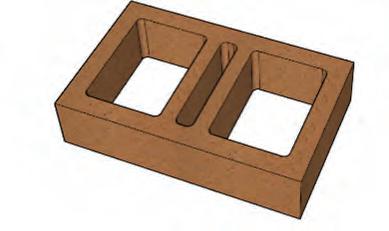
Ten-inch deep HCM units were chosen for the single-wythe wall. The unit size used for this case study was 10 inches deep by 4 inches tall by 16 inches long, (nominal dimensions), called a 10416 unit, with two large rectangular cells adjacent to the end webs, and a single narrow cell in the center (Fig. 1) The design assumes (requires) a fully grouted wall. Wall weight was calculated at 103 psf. The terms “fully grouted” or “solid grouted” (currently used interchangeably in TMS 402/602) allows for voids in the head joints between the mortared face shells (standard mortar bedding) of square ended units (for CMU and HCM) and should allow for the unfilled center cells of HCM and the large head joint voids for CMU units made with “ears” due to recessed end webs. These voids are generally assumed to remain unfilled when using standard coarse grout and standard grouting procedures. The tornado shelter walls were fully grouted to provide the durability needed for tornado shelter projectile impact resistance, per ICC 500, which has been proven via testing by at least one HCM
STRUCTURE magazine 18
Figure 1. The 10416 HCM unit is 10 inches by 4 inches by 16 inches.
manufacturer. Reinforcing also requires fully grouted walls.
This case study was based on Strength Design (SD) concepts (TMS 402 chapter 9) with f’m = 4,000 psi. The minimum grout strength (f’g) was chosen to equal f’m, so, f’g = 4000 psi, in accordance with TMS 602.
Per ICC 500, the tornado design wind speed (VT) from Figure 304.2(1) was 250 mph; roof live load was 100 psf, to account for wind borne debris landing on the roof; Exposure Category C is prescriptive; Topographic effects Kzt = 1.0; wind directionality factor, Kd = 1.0; gusteffect and internal pressure coefficient, GCpi = +/-0.55 (partially enclosed). This assumed GCpi coefficient may be conservative if the openings are properly designed and constructed for tornado wind and impact resistance, wherein +/- 0.18 is allowed.
the two noted appeared to be the most critical.
The assumed ground elevation for this example is 750 feet above sea level (Ke = 0.97).
For monolithic structural masonry walls, there is some debate as to the most appropriate derivation of the “Effective Wind Area” (EWA) used for Components and Cladding (C&C) design. EWA is part of several nomographs in ASCE 7 used to determine various pressure coefficients. With the amount of reinforcing anticipated in these walls the EWA was chosen to be 2L2/3, or double the minimum suggested (but not required) by the code. [An EWA of 2L2/3 was chosen because a monolithic wall most likely performs more like a plate or membrane for out of plane load distribution than discrete framing members like stud wall framing or roof joist/purlin framing]. For the roof C&C wind pressures EWA of L2/3 was used relative to the discrete roof framing members. EWA for monolith planar masonry walls is not universally interpreted as L2/3, with such variations as L x 6t; L x joint spacing; and/or L2 used by various engineering practitioners. Main wind force resisting system (MWFRS) wind pressures were used for walls acting as shear walls for wind blowing parallel to the wall, and C&C design wind pressures were used for wind perpendicular to the walls (which were not acting as shear walls for that load case). Maximum negative (suction) out-of-plane (OOP) design wind pressure for C&C design was -219.0 psf; maximum negative OOP design wind pressures for MWFRS design was -174.1 psf. Maximum C&C wind uplift pressure for the roof was -297.0 psf while the maximum wind uplift roof pressure for MWFRS was -160.0 psf.
The 100-foot-long walls were divided into thirds, horizontally, with movement joints; the 70-foot walls were divided in half with movement joints. The maximum design in-plane (IP) shear in the short 70-foot-long end walls derived from MWFRS wind pressures on the 100-foot-long walls was 57.45 kips per wall segment. For the 100-footlong wall, the IP design wall shear was 24.9 kips per wall segment.
Controlling Design Cases
Two particularly critical load cases for the tornado shelter emerge: 1) the 100-foot-long wall oriented perpendicular to the wind generating the highest C&C OOP suction (leeward side) and roof up-lift with no IP shear, and, 2) the 100-foot-long wall oriented parallel to the wind direction with MWFRS IP shear, while resisting the MWFRS OOP suction pressures and uplift forces on the tributary roof area. In this case, uplift exceeded the gravity loads on the wall, putting the wall into net tension throughout its height. Of course, all code prescribed load cases and load combinations must be checked and satisfied, but
Some consideration should be given to the assumed fixity at the base of the wall based on the detailing and construction at the base of the wall. A pinned base would have Mu-p-base = 0.0, and Vu-p-base = wLb/2; a fixed base would have Mu-f-base = wL2b/8, and Vu-f-base = 5wLb/8, where ‘b’ is the effective unit width, or length along the wall being considered, and ‘L’ is the span length. For this case study, a pinned base was assumed. Also, keeping the maximum moment away from the base simplifies the foundation design and will prove to be important when checking dowels.
EleMasonry software was used to facilitate the actual design and code checks. The main wall reinforcing that satisfies the various load combinations is shown in Figure 2.
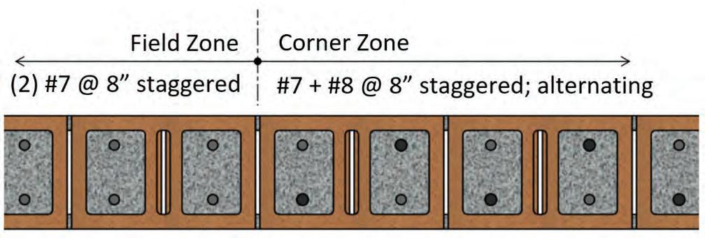
This is a lot of reinforcing, but the walls are nearly 30-feet tall with extreme winds. Horizontal steel selected was (1) #4 @ 48” o.c. vertically to meet code minimum bar size. The maximum vertical spacing allowed by code is 120 inches. Interestingly, deflection control is a main consideration and impacted the reinforcing selection.
The roof joists attached to the wall and the top courses of masonry must have sufficient tension capacity to resist the extremely large net uplift loads. Special detailing may be necessary to develop the reinforcing in tension at the very top of the wall to resist the roof joist uplift loads at their supports. (This could be steel bearing plates with fusion welded deformed bar anchors extending a sufficient length downward into the wall to lap with the vertical wall reinforcing. Another special detail could include also creating a 24-inch deep “beam-in-the-wall” at the top of the wall to facilitate developing hold-down reinforcing and spreading the joist reactions laterally would be a wise choice).
Using #3 180-degree hairpin dowels at the top of the wall to match the vertical reinforcing, placed to engage the top horizontal steel, is a good design choice.
Out-of-Plane Base Shear in Walls
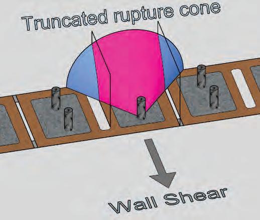
For most design cases, the OOP wind design pressures creating OOP shear at the base of the wall is generally not much of a design consideration, but it is something that requires some specific attention for tornado shelters—especially for tall walls due to the high OOP C&C wind design pressure. Procedures developed for “headed and bent-bar anchor bolt” design were used to check the wall base connection for OOP shear, substituting the foundation rebar dowels for anchor bolts. This is made somewhat more complicated because the center cell of the HCM units will likely be, and should be assumed to be, unfilled, as previously noted. This center cell void and head joint void can create a truncated shear cone, depending on dowel placement, for masonry breakout design checks, which is one of the two primary masonry strength items to check at the base of the wall
MAY 2024 19
Figure 2. Reinforcing of 10416 walls satisfied various load combinations.
for OOP forces. This truncated cone “devalues” the masonry shear breakout strength at the base connection of the wall. The other critical masonry strength design check is crushing of the masonry material (crushing the grout, actually) as the foundation dowels bear against the grout in the filled cells. For these checks, one generally assumes that the foundation dowels will match the vertical reinforcing and will be well developed into the foundation, most likely via hooks into the footings or pile caps, and well developed by sufficient development or lap lengths into the wall above the foundation. For this case study, prying failure and pull-out failure were not an issue. Lastly the rebar shear strength must be checked.
If all the vertical reinforcing is doweled into the foundation, it would be difficult to consider the base of the wall as a pinned connection. Consequently, a single #7 dowel was assumed, centered in the cell, at 16” o.c. as the sole reinforcing connection between the wall and foundation to represent a pinned base most closely.
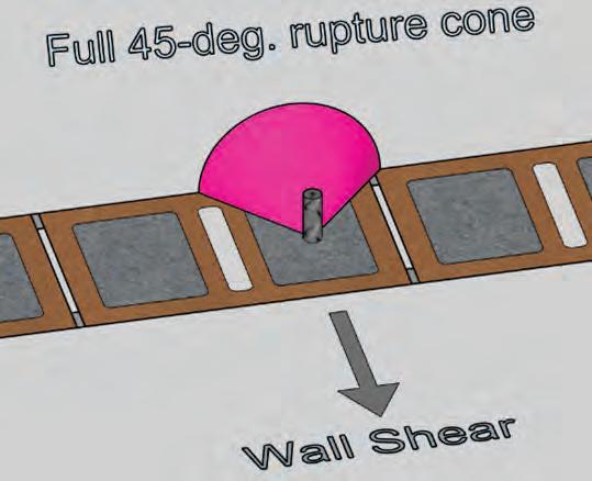
For the rebar dowel centered in the cell at the base of the wall shown in Figure 3, the rupture cone for the 10-inch deep units would be a full 45-degree half cone with a surface area of 44.08 in2. (For dowels placed at the maximum distance from the rupture face of the unit shown in Figure 4, the rupture cone would be truncated (devalued) as it passes through the plane of the head joint void and the plane of the center cell void – but still greater than the 44.08 in2.) The capacity reduction factor (Φ) for shear is 0.50 for masonry modes of anchor failure (breakout and crushing), and 0.9 [0.65] for steel modes of failure (9.1.4.1). Using the single #7 rebar dowel centered in the cell (left image above) the masonry breakout capacity (Eqn. 9-6 [9-4]) was ΦVnbOOP = 5.6 kips. The masonry crushing capacity (Eqn. 9-7 [9-5]) was ΦVnc OOP = 6.1 kips and the rebar shear capacity (Eqn 9-9 [9-7]) was ΦVnsOOP = 19.4 [14.0] kips, assuming full capacity of the steel.
The C&C Zone 5 wind pressure at the pinned base of the wall generated an OOP shear force of Vu = 4.2 kips at 16” o.c. The OOP shear capacities previously noted for the #7 dowels at 16” o.c. indicated that there was sufficient capacity at the base of the wall to resist the C&C OOP shear demand for the “non-MWFRS” walls – walls perpendicular to the wind direction. Utilization ratio = 0.22.
Checking combined wind effects: Some masonry design programs will only check IP and OOP loadings as separate load conditions, individually. For the MWFRS walls, IP and OOP forces act simultaneously so the design must account for those superimposed effects—basically a biaxial bending issue, plus shear, both IP and OOP shear. Combinations and utilization ratios vary with height, so several checks should be made to confirm that adequate strength is provided at various wall heights. So, after said checks were performed, the design was deemed adequate.
Also, consider checking shear friction at critical heights of the wall to ensure that uplift is not impacting the shear strength detrimentally. The default coefficient of friction, μ, value is 0.7.
Conclusion
The intent of this case study was to show that RHCM can be designed for tall walls under extreme wind loadings from tornados due to the inherent strength advantage of RHCM. Additionally, this case study
provided an opportunity to clarify the terms “fully grouted” and “solid grouted,” which may not be what most designers assume. Further, the question of determining the EWA for monolithic walls and wall elements is worth an additional discussion since there seems to be varying interpretations and little consensus of what is the “correct” EWA formula for monolithic walls.
By way of comparison, if this particular facility was to be constructed with CMU, using units with a net area compressive strength of 3,250 psi, the wall thickness would need to be a minimum of 12-inches deep; plus, for the finished brick appearance, which is one of the design imperatives, brick veneer or thin brick would need to be added to the CMU. A single wythe RHCM wall will always be less expensive than brick over CMU due to the reduction of materials and, most importantly, the reduction of labor to install one wythe versus two. Secondary benefits are more interior space and thinner/smaller foundations. [In general, walls designed for CMU can be swapped to HCM without any redesign, but the full efficiencies of the higher strength HCM material will be somewhat limited.]
HCM is a material that has the three building qualities espoused by Vitruvius - Firmitas, Utilitas, and Venustas, which means strength, utility/usefulness, and beauty. Consequently, RHCM can be used effectively to construct buildings with those same three qualities, especially for buildings with extremely high wind design pressures—like tornado shelters. Where tornado safety is a concern, building with RHCM is a viable solution. For the safety conscious, RHCM also has proven performance via testing for tornado driven projectiles, ballistic impact, and fire-resistive ratings up to four hours—for 8-inch deep units in a filled assembly. RHCM is an excellent choice where safety or protection of valuable assets is a design imperative. ■
Steven G. Judd, CE, SE, CBS is the Technical Director of Interstate Brick, a Western U.S. brick manufacturer. He is current Chair of several committees and task groups in Western States Clay Products Association, The Masonry Society, and Brick Industries Association, and is active in various other committees in those organizations as well as in ASTM committees and task groups related to masonry.
The author would like to recognize and give special thanks to John Hochwalt of KPFF Engineering, Seattle, Washington, for insight and assistance regarding shear in masonry walls under net tension.
STRUCTURE magazine 20
Figure 3. For the rebar dowel centered in the cell at the base of the wall, the ruptured cone is a full 45-degree half cone.
Figure 4. For dowels placed at the maximum distance from the rupture face of the unit, the rupture cone is truncated
BUILD TALL WITH POWER COLUMN ®
STRONG, EFFICIENT, SUSTAINABLE
POWER COLUMN® FEATURES
• Complement to Mass Timber wood framing systems
• Sustainable Forestry Initiative (SFI®) Certified
• Manufactured with superior strength southern yellow pine MSR Lumber
• Available in range of appearance grades for structural and architectural applications
• Superior alternative for Tall Wall applications
• Load path solution for Engineered Beam and Header Products
• Framing members such as Power Beam® can easily be attached to Power Column® with simple connection detailing


©Anthony Forest Products Company, LLC WWW.CANFOR.COM | 800.221.BEAM | WWW.ANTHONYFOREST.COM
Anthony Forest Products is part of the Canfor Group of Companies
Mass Timber Solutions for Affordable Multi-Family Housing
STRUCTURE magazine 22
Used efficiently, mass timber can be a cost-effective structural material to create sustainable, affordable housing.
By Michael Scancarello, PE, and Andrew Ruff
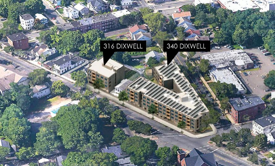
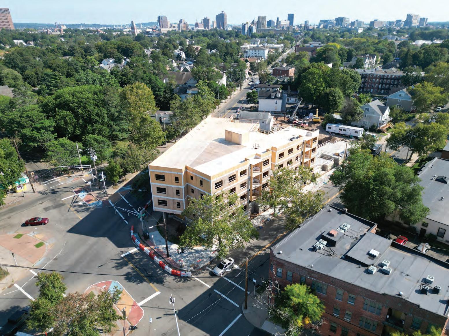
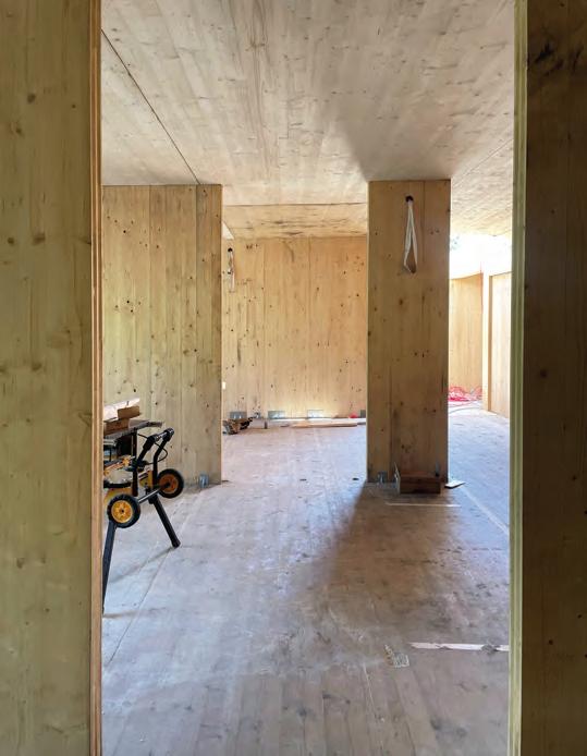
Mass timber structures are becoming more frequently studied as a leading choice for high-end residential and commercial structures for their sustainability and aesthetic benefits. Perhaps often overlooked, mass timber also belongs in the conversation when it comes to multi-family residential projects, including those classified as “affordable housing.” Providing 69 units of affordable housing along with ground floor retail while funded through typical methods for affordable housing projects, the 340+ Dixwell project is one project that demonstrates this possibility. While this article does not spend time addressing the funding or specifics of affordable housing, it will present challenges and solutions to successfully delivering a cost-effective mass timber structure in this typology.
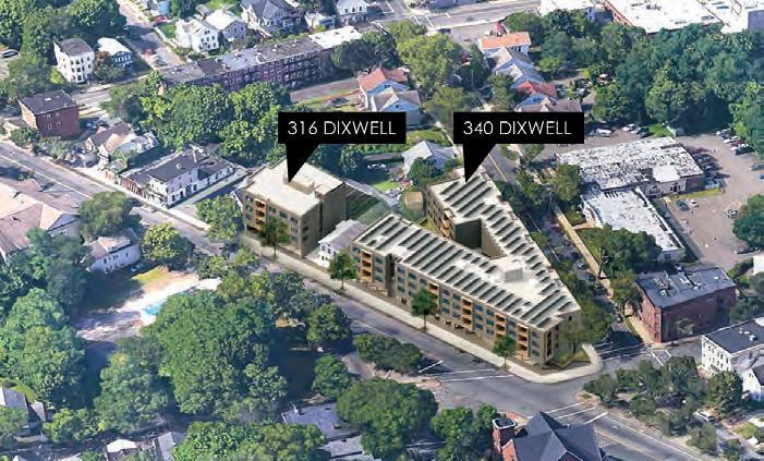
The 340 and 316 Dixwell buildings are each four-story structures comprised primarily of 5-ply cross-laminated timber (CLT) floor panels and 3-ply CLT roof panels that are supported on CLT bearing walls at unit demising and partition walls in addition to coldformed metal framed (CFMF) bearing walls at most corridor walls. The exterior walls, while typically non-load bearing, are also CLT. At the ground floor retail spaces, glulam timber columns and beams support the bearing walls above while steel framing and a composite slab on deck are used above exterior covered parking areas to minimize structural depth. On this project, the following key design considerations helped achieve the project’s ambitious goal of demonstrating the feasibility of mass timber affordable housing.
Know Your Construction Type
Typically, the building’s construction type classification as defined by the building code is not something that structural engineers will be particularly familiar with, and it is usually selected without substantial input from the structural engineer. However, when the architectural goals include exposing the structure without the use of applied fireresistant materials, knowing the options and limitations with mass timber systems is important. One of the first conversations between the structural engineer and architect (and likely code consultant) should be centered around selecting a construction type that can meet the project’s goals as efficiently as possible. In many cases, the construction type will drive the decision-making for structural layouts. This project was designed and permitted before the 2021 IBC provisions for mass timber in construction types went into effect, and was permitted as Type VA, with a 1-hour fire rating. However, it is likely that even had the new construction types within Type IV been available, the same code path would have been followed. The excerpt from the International Building Code (IBC) Table 601 summarizes some of the key structural considerations based on construction type. As can be seen in this table, both Type IIIA and Type VA require a 1-hour fire rating for most components of the structural system while
each of the new construction types—including Type IV-C, which generally allows for exposed timber surfaces—require a minimum 2-hour rating for the primary structural systems. When fire rating is provided by the code prescribed methods that account for charring of the timber frame, it is the author’s experience that 3-ply panels will typically be insufficient for meeting a 1-hour rating for most span conditions. However, at shorter spans, thin 5-ply panels will often be sufficient and even at more moderate spans this 1-hour fire rating will only moderately decrease the maximum permissible spans of 5-ply panels. When the fire rating requirement increases to 2 hours for exposed panels, the result is frequently a significant amount of wood fiber increase or a requirement for panel specific test data acceptable to the Authority Having Jurisdiction (AHJ). Reliance on fire testing at early stages of design and permitting often requires early selection of suppliers, which can be a challenge for projects that rely on public funding sources. Much like floor panels, when using CLT bearing walls exposed on one or both sides, the difference between a 1-hour and 2-hour rated structure can result in significant wood fiber increases. With glulam framing members, it has been shown that a 1-hour fire rating can be achieved for glulam beams exposed on three sides that meet the traditional “heavy-timber” minimum sizing without significant impact on member sizing. However, like CLT, when a 2-hour fire rating is required, it is likely to control the design for most efficient beam sizes. (Glulam members with a non-uniform layup have additional requirements that may increase cost over an unrated structure even when timber volumes do not change.) Finally, while a structural system with any rating requirement also requires rated connections, 1-hour fire ratings are more easily achieved without significant impact on member sizing or aesthetics. The footnotes of IBC Table 601 are important to understand. Footnote c, which has been clarified in the 2021 IBC, allows for the use of heavy timber for roof construction in many situations. Heavy timber requirements are generally less restrictive than those of a prescribed one-hour rating and were used at this project to reduce the panel thickness—and cost—of the roof structure.
MAY 2024 23
Figure 1. The buildings at 340 and 316 Dixwell are comprised primarily of 5-ply cross-laminated timber (CLT) floor panels and 3-ply CLT roof panels supported on CLT bearing walls.
Design for Flexibility
A key factor in successful mass timber projects is the early selection of a mass timber supplier. However, waiting as long as possible to commit to a particular manufacturer also has advantages. In some cases, like affordable housing, the timing of bidding and selection may also be dictated by funding streams. In the case of this project, a substantially complete design was needed prior to onboarding a supplier. This requirement allowed for a competitive bid process which, while a requirement here, is an approach more familiar and comfortable for many owners and developers accustomed to utilizing conventional structural systems.
Leverage Material Strengths
This process can provide competitive pricing, but in the U.S., CLT is not sold as a commodity product in the same way as steel or concrete. Most manufacturers produce a variety of panels as slightly different products with different constraints tied to materials, manufacturing processes, and transportation limitations. This presents a different challenge for the design team than many may be used to.
When a supplier is onboarded early, the design team’s goal is to optimize their solution for the selected supplier. Conversely, in a competitive bid, the design team must ensure the design is compatible with as many suppliers as possible. In this scenario there is more responsibility on the design team to be familiar with the capabilities and strengths of multiple suppliers. In the case of 340+ Dixwell, the design team was able to rely on previous experience working with several of these suppliers as Architect and/or Engineer of Record (EoR), Delegated Design Engineer, or both. However, when that experience is not available, it is recommended to communicate with as many suppliers as possible at multiple steps of the design process. Even with ample experience, frequent feedback from suppliers can help the team ensure that their design does not preclude suppliers from bidding or put unnecessary constraints on them that would limit their ability to provide competitive pricing.
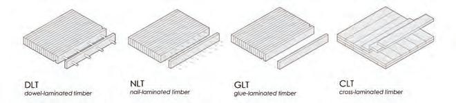
As a simple spanning element, CLT is often not as efficient as other panelized timber elements like Nail-Laminated Timber (NLT) or Glued-Laminated Timber (GLT) decking which orient dimensional lumber stacked on edge, placing all fibers in the primary strength direction of the panels. However, by placing the panel fibers in alternating directions, CLT provides several distinct advantages that can make it an efficient choice (Figure 2).
In addition to providing dimensional stability in both axes perpendicular to the face of the panel, CLT panels also have significant in-plane shear strength, making them suitable to be used as diaphragm elements when properly joined together. The ability to use the CLT as a diaphragm and eliminating the need for the topping slab to be structural allowed the design team to study non-cementitious topping systems. Although ultimately not selected for this project due to budgetary constraints, a dry lay assembly could reduce the embodied carbon and reduce the number of “wet” products applied over the timber, potentially providing a schedule savings. With new products and data continuing to become available, this could become a beneficial alternative in the future for projects where a cementitious topping is not required by code. CLT panels also provide flexural capacity in two directions. While creating true fixity across panel joints is very difficult, if supported frequently enough, it is possible to achieve two-way spans with individual panels. Some notable mass timber projects have leveraged this and utilize fully point-supported panels with closely spaced columns. At 340+ Dixwell, this attribute of CLT was used to provide beam-free
c. In all occupancies, heavy timber shall be allowed where a 1-hour or less fire-resistance rating is required.
STRUCTURE magazine 24
Building Element Type I Type II Type III Type IV Type V A B A B A B HT A B Primary structural frame (see Section 202) 3a 2a 1 0 1 0 HT 1 0 Bearing Walls Exteriore, f Interior 3 2 1 0 2 2 2 1 0 3a 2a 1 0 1 0 1/HT 1 0 Nonbearing walls and partitions Exterior See Table 602 Nonbearing walls and partitions Interiord 0 0 0 0 0 0 See Section 602.4.6 0 0 Floor construction and associated secondary members 2 2 1 0 1 0 HT 1 0 Roof construction and associated secondary members 1 1/2b 1b,c 1b,c 0c 1b,c 0 HT 1b,c 0
Figure 2. Different panelized mass timber products are presented.
IBC Table 601. Fire-Resistance Rating Requirements for Building Elements (Hours)
corridors as well as beam-free zones within primary bearing lines, allowing MEPFP distribution to be kept tight to the ceiling. Early coordination between the structural and building systems were critical to ensure that a 10 foot-6 inch floor to floor height could be achieved while maintaining an 8-foot ceiling height within the portions of units with dropped ceilings. As part of the early design process, multiple framing options were presented for review and coordination, and the choosing by advantages method (a decision-making process, often used by the authors, taken from lean construction practices) was used to select the preferred choice. While the authors have frequently found that spanning CLT panels across the width of double loaded corridor residential buildings results in efficient layouts for non-bearing wall structures, because of the architectural desire for exposed CLT partition and demising walls it was determined that eliminating additional framing members and spanning the CLT panels directly between these walls provided the most advantages to the project. This decision then drove revisions to architectural layouts to improve the efficiency in panel selection.
The two-way spanning capability of CLT was leveraged at two primary conditions that repeated throughout the building. First, corridors were designed to be beam-free by utilizing corridor walls as bearing walls, a strategy commonly used in traditional light-frame construction. To accommodate the different capabilities of potential suppliers, these spans were confirmed to work in two different ways. For manufacturers who could provide the exterior laminations (and therefore primary strength direction of the panel) in the short direction of the panel, panels would be able to span directly across the corridor and either 3-ply or 5-ply panels would be sufficient. However, for suppliers who primarily supply panels with the outer laminations parallel to the length of the panel, spans were confirmed to be acceptable for the panel to span in the weak direction of the panel, including the impacts of fire rating. This flexibility prevented the need to have multiple short span corridor panels that would increase the number of pieces to erect.
Near the corridor, door openings between bearing walls were sized to allow for panels to span these openings while being supported on wall panels only, without any headers above the door. This arrangement was stacked on each floor to ensure no concentrated loads would occur above unsupported sections of the CLT. Additionally, these openings were aligned from unit to unit so that consistent panel layouts could be used throughout the building, maximizing repetition and reducing restrictions on panel layout (Figure 3).
The requirement to provide beam-free corridors and door openings without using headers placed two constraints on the decisions driving the layout of floor panels, slightly minimizing opportunities for efficiency. However, by grouping these constraints together in the center of the building, the area of impacted panels was reduced. Additionally, choosing corridor and door widths and locations that didn’t push the limits of individual panel widths, multiple solutions were available to allow suppliers flexibility in the final approach.
The Role of the Engineer of Record
In part due to the uniqueness of each supplier, it was determined that a delegated design would make the most sense for the final mass timber package. This would allow the selected supplier as much flexibility as possible to reduce costs by tailoring their solution within the constraints outlined by the design team. However, to sufficiently finalize the design without running the risk of changes that could not be mitigated during construction administration, it was important for the engineer of record to be very involved in developing the design of
the mass timber systems by providing:
• A range of expected wall thicknesses for each supplier so that appropriate tolerances could be built into the floor plan, allowing for slight changes in dimensions without impacting code required dimensions. The architect then set all unit dimensions based upon centerlines of the mass timber and ensured there was room for these walls to grow or shrink as dictated by the supplier’s available products while maintaining critical required interior dimensions and clearances.
• A range of expected floor thicknesses to ensure adequate clearance for required MEP routing while working with the exterior wall detailing. The thickness of the floor assembly was used to set floor to floor heights. This project also aimed to aid the speed of erection by minimizing piece counts by using single panels where the width of the panel was the floor-to-ceiling height in the platform type construction, allowing for an entire wall segment to be comprised of one piece of CLT. Therefore, heights were also limited by the maximum panel widths a manufacturer could produce (Figure 4).
• Guidance on the limitations of suppliers, particularly as it pertained to maximum panel dimensions that would impact the ability to use single panels as bearing walls and where the location of openings might dictate panel layouts. Corridor layouts were confirmed and door locations within units were set to provide maximum flexibility to systems distribution and panel layouts as described in detail previously.
• Anticipated timber connection details at any locations where they would impact the architecture and at the interface between different trades, including connections to supporting concrete
MAY 2024 25
Figure 3. The MEPFP routing zones maximize repetition and reduce restrictions on the panel layout.
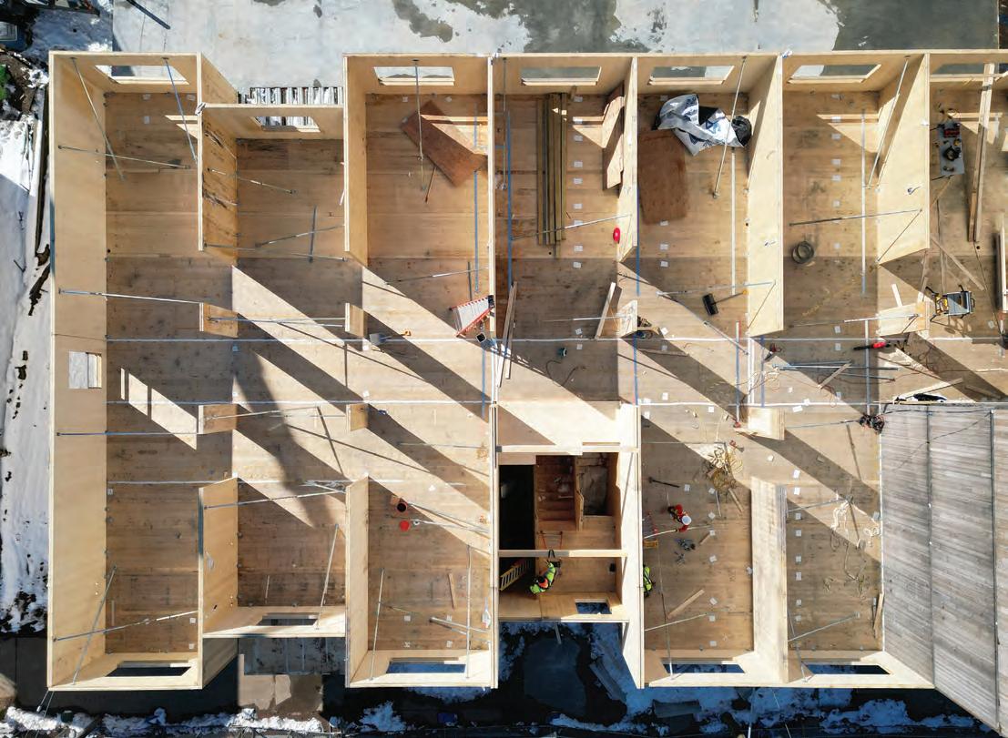
and steel elements. The authors attempted to allow the greatest flexibility to each supplier’s preferences, however the design team also had to be proactive to provide details that helped to dictate conditions that may increase the scope of one trade to simplify constructability and coordination between trades and/or improve the product that is ultimately delivered.
• Providing guidance on floor plan inefficiencies that will impact costs. Early unit layouts typically had a framed drywall surface applied to one side of all CLT walls to provide acoustic separation and vertical routing of building systems. However, after selection of a code path and structural system, this drywall was standardized to be continuous on the same side of each wall for the full length of the wall and height of the building instead of alternating where architecturally preferred so that it could also be used to provide the fire resistance rating for exposure on one side of the wall. By using materials that would already be present, the total wood fiber requirements for the walls were substantially reduced. Typical bearing wall to bearing wall dimensions varied throughout the building in initial unit layouts. After the selection of the framing approach, unique layouts were moved to areas of the building where site constraints would require unique solutions, maximizing repetition in the primary structural layout and allowing for uniformity in most governing spans, therefore allowing for more panel thickness reductions.
Inexpensive Buildings Don’t Need to Feel Cheap
By leveraging the strengths of each unique material and following through on good design decision making, the new affordable housing units on Dixwell Avenue are proving it is possible to build high-quality affordable housing on a tight budget. It is possible to use mass timber as a cost-effective and biophilic element in a sustainable fashion on a project that will be certified to PHIUS passive house energy efficiency standards. It is also possible to introduce new materials to the market and build up a skilled local workforce to construct these buildings. Every project presents opportunities to learn from as we continue to improve what we build, how we build, and who we build it for. This project was informed by many before it and the authors hope its demonstrated successes, as well as its recognized challenges, will contribute to continued improvement in our industry. ■
STRUCTURE magazine 26
Figure 4. This aerial photograph taken during construction shows the full-width walls.
Michael Scancarello, PE, is a Project Director at Odeh Engineers, a member of WSP. He is passionate about sustainable structures and is an Embodied Carbon Champion in the firms commitment to SE2050.
Andrew Ruff is the Research Director at Gray Organschi Architecture in New Haven, Connecticut, and a Visiting Critic at the Yale School of Architecture.
Investigating a Collapse
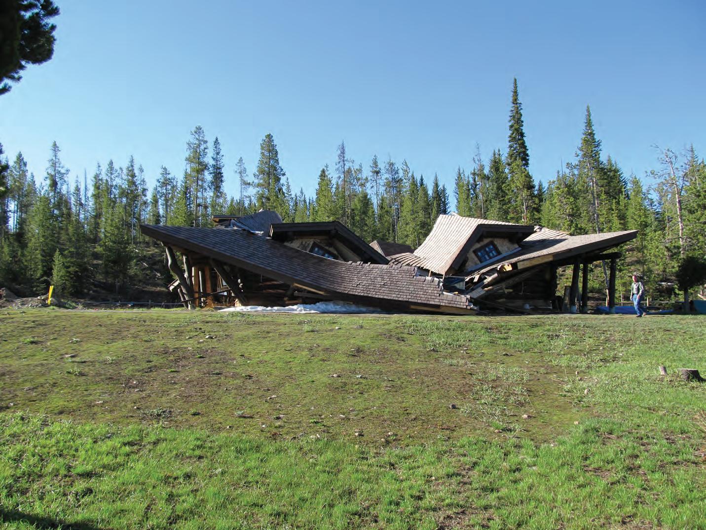
The case study of a lodge collapse provides considerations for structures under construction. By Peter
Despite adequate structural design and a less-than-design snow event, a scribed log- and sawn-lumber-framed commercial lodge structure experienced a catastrophic collapse less than two years after it was built. The subsequent investigation involved a piece-by-piece selective dismantling of the debris pile to determine the cause of the devastating failure.
The recreational ranch facility where the subject building was located is a vacation-type resort situated on leased federal land in a high alpine environment of the Rocky Mountains. The summer activities of the ranch cater to horseback riding, hiking, bike riding, and exploring the nearby national park. During the months of October to April, the area where the ranch is located can receive upwards of 20 feet or more of snow, making wintertime access by tourists impractical for some and infeasible for others.
Under the terms of the ranch owner’s long-term land lease with the United States National Forest Service, the ranch was permitted to construct permanent structures on the property. As part of a broader facility expansion, the ranch owner began procuring plans for an approximate 3,100-square-foot, one-story fourplex log building that included a wrap-around exterior wooden deck. The plans for the log building were developed by a professional engineer who was licensed in the state where the structure was to be built. The snow loads specified in the construction plans were appropriate for the proposed location of the log building.
The ranch owners/managers were acting as the general contractors for the project. The onsite log erection/assembly, roof covering installation,
and rough framing of some of the interior walls took place in early summer. The interior finishes, including interior drywall, insulation, floor coverings, electrical wiring, plumbing, and HVAC equipment, were not installed before the onset of the first winter. Due to project financing issues, all construction progress stopped, and the project remained incomplete for the first winter, the following spring, summer, and fall. The status of the project remained nearly unchanged for the second winter season.
On May 1, the building collapsed catastrophically (Figure 1). The damage was significant and global. It was believed that only the concrete foundation could be reused if the structure was to be rebuilt. Information provided by witnesses who discovered the collapse indicated that 10 or more feet of snow and a thick layer of solid ice had accumulated on the roof at the time of the collapse.
Unified Building Sciences and Engineering, Inc. (UBSE) was hired by an insurance company to determine the cause of the building collapse. As part of the investigation, USBE conducted a site visit once the roads became navigable, approximately one month after the collapse. Based on a detailed review of the weather records, the maximum roof load during the first winter after the initial construction was determined to be 20 to 30 pounds per square foot. The maximum roof snow load on May 1st at the end of the second winter was determined to be 60 to 70 pounds per square foot.
USBE visually and tactiley inspected the logs, framing, connectors, and foundation as part of the investigation. The structural members were still in a near-new state. No corrosion, decay, rot, or deterioration
MAY 2024 27
Marxhausen, PE
Figure 1. The commercial lodge structure collapsed catastrophically less than two years after it was built.
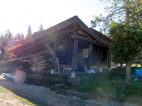
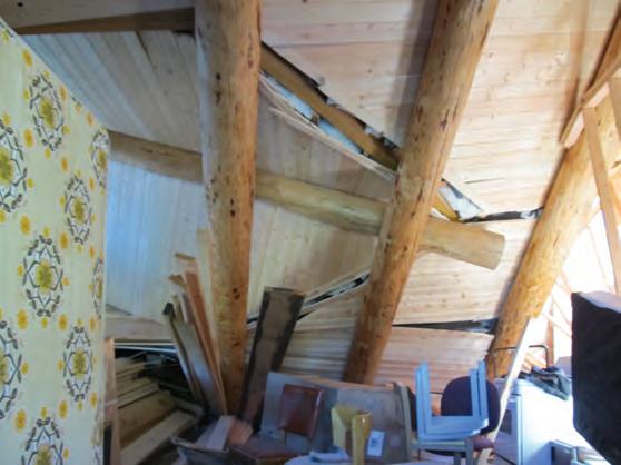
was observed that could have caused or contributed to the building collapse. Aside from the stresses imparted by the collapse, the logs were in good condition and well-suited for their intended function. Similarly, conditions were not observed that would suggest the logs or dimensional framing were improperly fabricated, shipped, or assembled onsite.
The configuration of the building debris after the structural collapse indicated that the failure originated near the center of the building. USBE analyzed the design that was set forth in the construction documents and determined, before the inspection, that the beams, headers, and roof trusses were appropriately designed for the anticipated loads and would have been expected to endure the snow loads that were presented in the weather records.
The approved construction plans specified that the roof structure was to be vertically supported by two triangular-shaped log frames that would be vertically supported along the bottom chord by two 12 foot tall first-floor 2x6 stud-framed interior load-bearing walls. The roof ridge was also to be supported in the transverse direction with two back-to-back 2x4 continuous walls that were to serve as the fire assembly party walls.
The examination of the physical evidence located within the building collapse revealed the following:
• The two 2x6 first-floor interior load-bearing walls were installed; however, they were not sheathed with a gypsum wallboard panel product as specified in the approved construction plans.
• The lack of wall sheathing violated the National Design Specification for Wood Construction (NDS) slenderness ratio for solid columns and rendered the studs vulnerable to weak axis buckling.
• Without sheathing, the code-permissible (allowable) load-bearing capacity of the 2x6 wall was effectively 0 (zero) pounds per square foot; however, the calculations indicate the ultimate (failure load) capacity would have been reached with approximately 55 to 65 pounds per square foot of snow on the roof.
• Blocking had not been installed between the studs that comprised the central 2x6 load-bearing wall.
• The two back-to-back 2x4 continuous first-floor party walls specified on the plans were not installed. The failure to install the specified walls resulted in the roof ridge being vertically unsupported; however, at a laterally unsupported height of 18 feet, these 2x4 walls would have had an ultimate capacity (failure load) of less than 5 percent of the applied load.
• The 2x6 studs that comprised the center load-bearing walls buckled
and collapsed under heavy snow loads in early May. The compression buckling of the load-bearing walls caused the log roof frames to fail and the roof structure to come crashing down through the first-floor framing into the crawl space.
Discussion
The conventional 2x4 and 2x6 sawn lumber wall framing was sufficiently tall that Euler buckling action controlled the allowable design load. Had the 2x6 stud framing been sheathed/covered with gypsum wallboard, the calculated allowable axial load for Douglas-Fir No. 2 wooden studs would have been approximately 5,000 pounds per stud with the expected mode of failure being in the direction of the strong axis. The ultimate (failure load) would have been approximately 14,000 pounds per stud in the direction of the strong axis. Without the gypsum wallboard sheathing, the allowable axial load of a Douglas-Fir No. 2 wood stud would have been approximately 400 pounds per stud due to weak axis buckling, and the ultimate (failure load) would have been approximately 1,120 pounds per stud.
The NDS limits the slenderness ratio of axially loaded members to 50 or less for in-service loads and 75 or less for construction loads. A 12-foot tall 2x6 stud without blocking has a calculated slenderness ratio of 96, which means the stud wall framing, as it existed at the time of the collapse, was not suitable to receive service or construction loads.
Conclusion
Based upon the forensic structural engineering evaluation of the building collapse, the following conclusions were reached:
• The structure was appropriately designed for the local design ground snow load of 175 pounds per square foot.
• The fourplex log building collapsed due to the general contractor’s failure to install the interior load-bearing walls in conformance with the plans.
• The interior load-bearing stud walls were not covered with gypsum wallboard sheathing at the time of the collapse. Without the gypsum wallboard sheathing attached to the narrow face of the studs, the wood studs were vulnerable to buckling along the narrow/weak axis.
• Had the gypsum wallboard been installed, the axial capacity of the
STRUCTURE magazine 28
Top left: Figure 2. The loss of integrity of the roof framing placed outward forces on the exterior walls, which caused the perimeter log walls to lean outward. Top right: Figure 3. This view shows the interior of the collapsed structure with finishes and furnishings in place.
wood wall studs would have been approximately 12 times greater.
• The general contractor did not r specifically the gypsum wallboard, were necessary for the load-bearing wall to support the anticipated loads.
• The structural engineer did not anticipate that the construction might stop for two winters, leaving the load-bearing wall without the sheathing that was needed to prevent weak axis compression buckling of the wall studs.
• When the load-bearing interior stud walls w moderate loads due to an accumulation of ice and snow on the roof, the individual 2x6 studs within the two primary interior support walls buckled. The buckling of the load-bearing walls caused the supported roof structure to collapse downward. The loss of integrity of the roof framing placed outward forces on the exterior walls, which caused the perimeter log walls to lean outward, leading to a large-scale catastrophic collapse (Figure 2).
• The collapse could have been avoided had the structural engineer of record been notified of the work stoppage and the incomplete status of the load-bearing wall construction. Similarly, had the plans and notes indicated that some finishes, such as the drywall, were needed to support the loads that were likely to occur, the general contractor may have been alerted to the need to sheath the walls before stopping work.
The structural members in this building were appropriately sized for final finished conditions. However, proper considerations were not in place to account for loads encountered during the construction period. Although the construction documents communicated that the interior load-bearing walls were to receive sheathing, it was not understood by the builder or the property owner that the specified sheathing needed to be in place before stopping the work for the duration of the winter. Had the structural engineer of record been informed of the state of construction and the desire to stop work, the collapse could have likely been avoided.
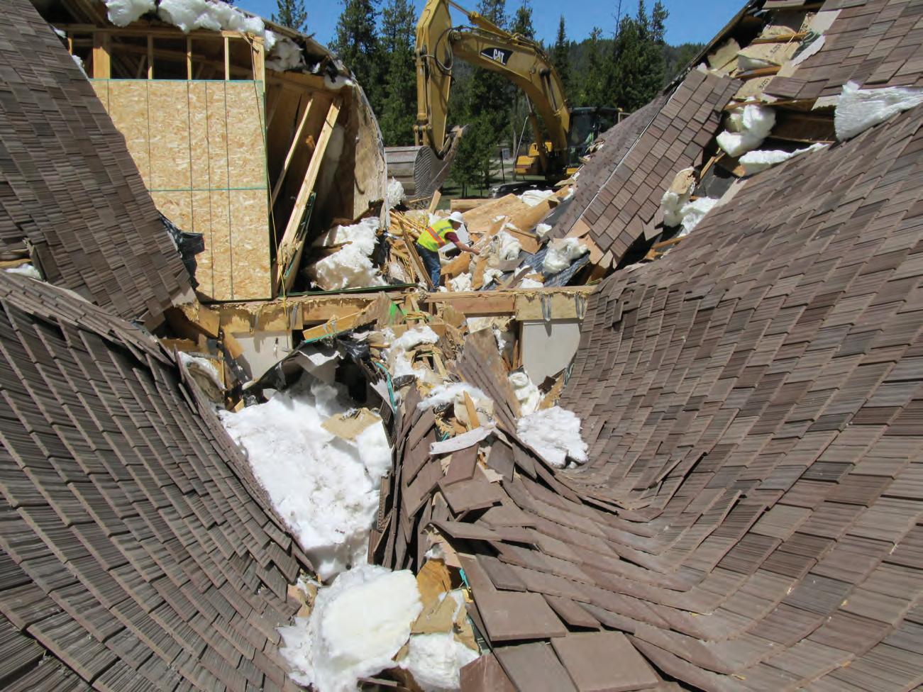
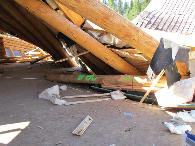
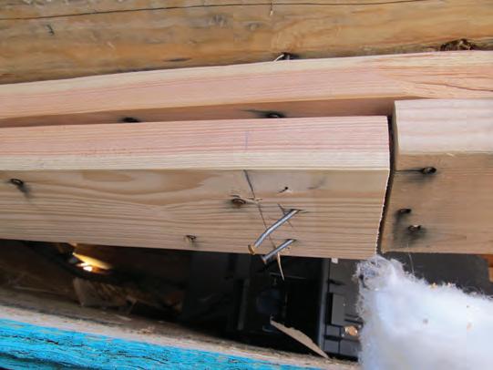
MAY 2024 29
Peter Marxhausen, PE, is a full-time forensic structural engineer with Unified Building Sciences and Engineering, Inc. (UBSE) and a part-time non-tenure professor of civil engineering at the University of Colorado Denver. (pmarxhausen@ubse.com
Figure 6: The evidence revealed that the load-bearing wall studs were not sheathed to prevent weak axis buckling. The floor sheathing and the double top plate are shown, which, with the studs, should have been 10 feet apart. The wall studs had all buckled and become widely displaced.
Figure 5. The center load-bearing stud wall was the critical structural element that failed.
Figure 4. The investigation initiated at the center load-bearing wall and used two tracked excavators to remove components.
Reviving a San Francisco Bay Area Historic Landmark
The seismic ductility and health monitoring of historic wood connections in a WWII airship hangar were enhanced using fully threaded screws.
By Kenneth Ogorzalek, PE, SE; Blake Dilsworth, PE, SE; and Shakhzod Takhirov, Ph.D, PE
Have you ever walked into a garage or a shed and discovered timber defects in structural elements that made you think twice about needing to fix them? Often, we ignore these early warning signs simply because it is easier to turn a blind eye and close that garage door with the hope of standing on conservative designs and inherently redundant structures. Now, imagine that garage was 173 feet tall, 300 feet wide, and 1,000 feet long with over 4 million board feet (FBM) of lumber; and it was designated as a historic structure in the National Register of Historic Places (NRHP) while maintained by the U.S. Navy and subsequently, NASA. Observations of timber checks, splits, warps, and any other defect that crosses your mind have a whole different meaning when staring into an abyss of wood. This was exactly the case when KPFF stepped into the Moffett Federal Airfield (MFA) Hangars 2 and 3 in 2013.

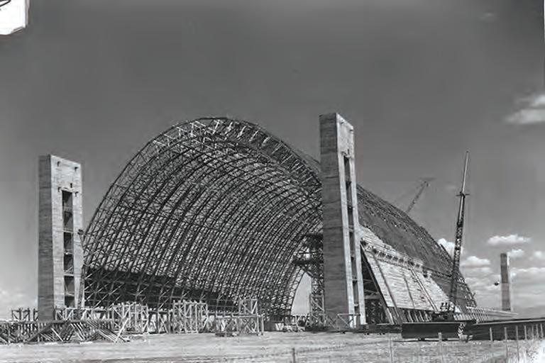
STRUCTURE magazine 30
Figure 1. Moffett Federal Airfield LTA Hangars: (below) Hangar 2 during construction in 1943 (photo from the U.S. Navy); (opposite page left) an aerial image of Hangar 2 on the left and Hangar 3 on the right in 1968 (photo from the U.S. Navy); (opposite page right) a map of LTA Hangar locations and their current-day status.

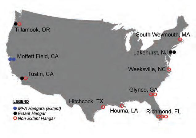
MAY 2024 31

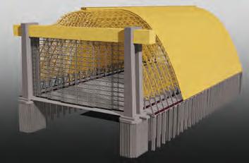
Project History
Hangar 2 (H2) and Hangar 3 (H3) were built in 1943 in Mountain View, California, by the U.S. Navy to aid WWII efforts and the Lighter-Than-Air (LTA) program. Constructed in 12 and 7 months, respectively, H2 and H3 are 2 of 17 similar hangars constructed along the west and east coast of the U.S. (Figure 1). The hangars primarily housed the U.S. Navy blimp fleet for submarine patrol, as well as dirigibles (rigid airships) when needed. A single hangar consists of 51 parabolic timber arched trusses spaced at 20 feet on-center and on top of two-story portal frame concrete bents supported by concrete pile caps and timber piles. Each truss was constructed from erection units containing timber chords and web members ranging from 3x8 to 6x14 in size, and were connected to one another by split rings, shear plates, and/or bolts. Independent door structures consisting of concrete towers connected by a spanning box beam are at each end of the hangars. A seismic joint separates the main hangar from the door structures.
All 17 LTA hangars were built from the same structural drawings and specifications, with some minor optional variations. LTA was part of the Accelerated Public Works Program of the Navy in aid of the war efforts, so the hangars were designed in a way to maximize efficiency and speed. At the time in 1942, this meant that the project structural engineer was able to use slightly higher member and connection capacities while simultaneously using slightly lower force demands when compared to code requirements. In addition, it was acceptable to use improperly seasoned timber to expedite construction. The hangars were created strictly to support WWII efforts, so these notions were approved since their life necessity was only 5 years. Remarkably after 82 years of service, six of these hangars still stand (Figure 1). In November 2023, one of the Tustin, California, hangars tragically burned down. This hangar put up a good fight and in certain on-site photos it was observed that the west side of all 51 wood arches still stood after the fire. This speaks to the level of redundancy within the original structural system relative to a 5-year design life, which is exactly what we have also observed in the MFA hangars.
H2 and H3 are not new to being studied. More recently, Rutherford & Chekene (1992), Neal Engineering Associates (1993), and Degenkolb (2006) have all provided their expertise. Starting in 2013, KPFF designed a voluntary upgrade to the portion of hangar H2 to ASCE 41-13 seismic demands per Life Safety (S-3) performance objective under the BSE-1N hazard level, as well as to ASCE 7-10 wind demands for a 700-yr event (95 mph). Given the complexity of the hangar, extensive condition assessment by visual inspection and 3D laser scanning was conducted on H2 to accurately document all in-field conditions. This allowed for better representation in our sitespecific seismic time history analyses, site-specific wind tunnel testing, and progressive collapse emergency repairs for hangar H3 (Figure
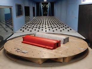
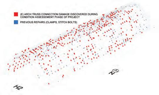
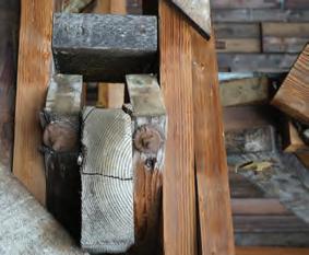
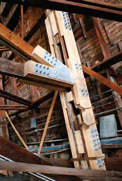
2). One upgrade item that was installed in the hangars included the strengthening of various arch truss wood connections, which is the focus of this article.
Wood Connection Strengthening
A single hangar contains 3,774 primary truss panel points, so strengthening of existing timber arch connections was a top concern. During the condition assessment phase of the project (Figure 4), numerous timber connection defects such as longitudinal splits, shear plugs, net section rupture, and bearing failures were identified. These connections are traditionally strengthened by anti-check bolts, clamps, or robust sistered members with bolted steel gusset plates, all of which can be time consuming and costly to install within the hangars because of difficult access constraints (Figure 3). Some of these strengthening techniques can even harm a structure by restraining the connection and the in-framing elements from translating or rotating during a wind or seismic event.
KPFF developed a simple, elegant, and highly strategic
STRUCTURE magazine 32
Figure 2. (Above) 3D laser scanning of full hangars; (center) Revit model [partial] for renovation coordination; (right) wind tunnel testing [H3 on left, H2 on right] (photo from RWDI).
Figure 3. (Top) An example of the KPFF condition assessment visual database for H2 connection damage and historic repairs (image from Sam Delwiche); (left and right) anti-check bolt and robust sistered member/steel gusset plate strengthening were observed in the hangars.
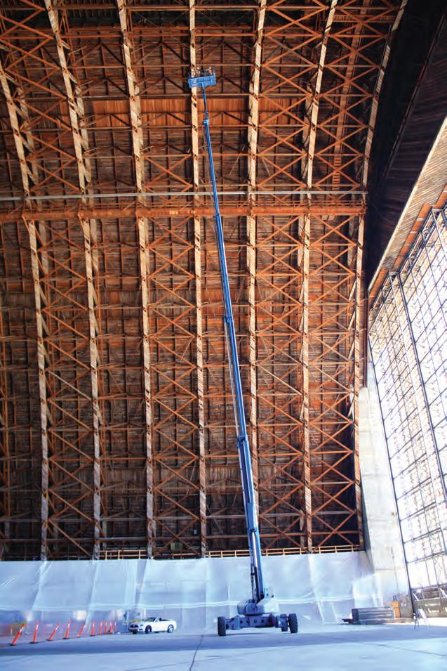
concept to repair the defects as well as enhance the strength and ductility of undamaged split ring and shear plate connections while accommodating inherent limitations. The concept is an extension from research by Mohammad and Quenneville (1999, 2000) and Bejtka and Blaß (2005). The solution uses modernday mass timber self-tapping SWG ASSY VG Plus fully threaded screws manufactured by MTC Solutions (formerly MyTiCon) and is designed to be installed within seconds rather than hours. These specific fully threaded screws are lightweight, have a high withdrawal capacity, do not require pre-drilling (confirmed by KPFF in-field drilling tests) nor prep work, and do not require complete spatial access around a connection for installation. The historic aesthetic impact of screw installation is also minimal since the screw head and washer, if used, are the only exposed surfaces.
Although the SWG ASSY fully threaded screws currently have an ICC-ES evaluation approval, KPFF conducted full-scale experimental testing at the University of California at Berkeley, Structures Lab, to more accurately quantify the increased strength and ductility of different screw strengthening configurations for both split ring and shear
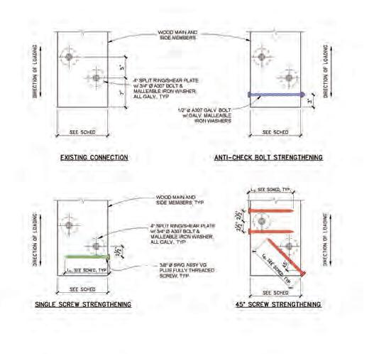
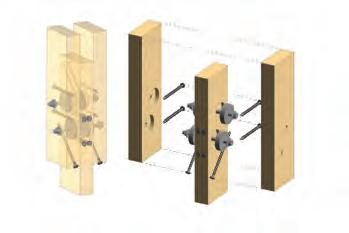

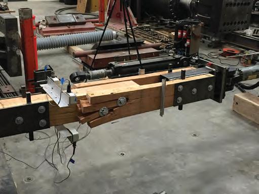
plate connections. A typical hangar arch truss connection was used to develop the testing specimen, and five different strengthening concepts were investigated: the historic anti-check bolt versus an equivalent single fully threaded screw, as well as a variety of different fully threaded screw orientations (Figure 5 presents four out of the five strengthening concepts for brevity). A total of 73 specimens were tested, handled, and fabricated according to ASTM D1761/D4442/E2126 and ASCE 41-13. The testing included monotonic (ASTM protocol) and cyclic (CUREE protocol) loading, thereby representing wind and seismic effects, respectively. A majority of the specimens were fabricated with new Select Structural Douglas-Fir wood (typically two 3x8s connected to a central dapped 4x8), 4” Ø SAE 1010 hot rolled carbon steel split rings that were galvanized per ASTM A123, 4” Ø malleable iron shear plates per ASTM A47/D5933, and A307 steel bolts. However, a portion of the testing program investigated and used extracted wood and connectors from Hangar 3.
The experimental testing results were precisely what KPFF had envisioned. It was evident after the first few tests that the fully threaded screws provided strength where wood is weak in cross-grain tension,
MAY 2024 33
Figure 5. (Top) During experimental testing, different specimen
Figure 6. Experimental testing is performed on full-scale unstrengthened wood connections under cyclic loading.
Figure 4. Hangar 2, which is 173 feet tall, 300 feet wide, and 1,000 feet long with over 4 million board feet (FBM) of lumber, is given a condition assessment.
Figure 7. Shown are monotonic compressive and tensile forcedeformation comparisons of example split ring connections: unstrengthened [highly brittle response] vs. anti-check bolt and single screw strengthening.
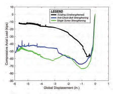
similar to the way steel rebar functions in reinforced concrete. All split ring and shear plate connections enhanced with fully threaded screws, as well as the anti-check bolt, exhibited increased strength and ductility when compared to an “unstrengthened” connection, while also simultaneously resisting perpendicular-to-grain splitting and minor secondary stresses of prying. Key takeaways and KPFF recommendations from the experimental testing program include:
• “Existing” unstrengthened connections exhibited ASCE 41-13, Fig. 7-4, Type 3 brittle failure force-deformation curves for both monotonic and cyclic tests (Figure 6). Unstrengthened connection tests turned out to be an expensive way to split wood for a bonfire, but all screw and anti-check bolt strengthened connections exhibited ASCE 41 Type 1 ductile behavior.
• The single screw strengthening proved to have similar response to the historic anti-check bolt strengthening (Figure 7). However, the single screw option is more efficient with installation time and therefore is recommended to use.
• The 45° screw strengthening proved to have the largest strength and ductility increase for both split ring and shear plate connections under monotonic and cyclic loading, as this was the intent of this strengthening option. The 45° screw orientation was implemented to take advantage of the screw’s high withdrawal capacity, which is about three times larger than the screw lateral shear capacity. Even under cyclic loading, the 45° screw connection strength increased by up to 34% and with a ductility factor of 9 (Figure 8).
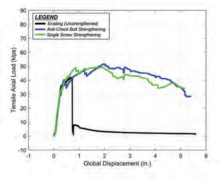
• Fully threaded screw head pull-through failures were observed. However, the pull-through occurred at deformations well beyond code requirements. KPFF recommended installation of washers under the screw head (for cylinder heads) in order to increase bearing resistance against member side grain and ultimately to achieve a higher connection capacity.
• Internal and external hydrogen embrittlement of the fully threaded screws was not directly studied during the experimental program. However, KPFF considered these factors during the hangar upgrades and provided a slightly more conservative design threshold for strengthening in-field hangar connections, even though the in-field screws are in a constant state of relatively dry conditions since installed on the inside of the hangars. KPFF recommends contacting your structural fastening hardware supplier for more information about individual internal hydrogen embrittlement management policy.
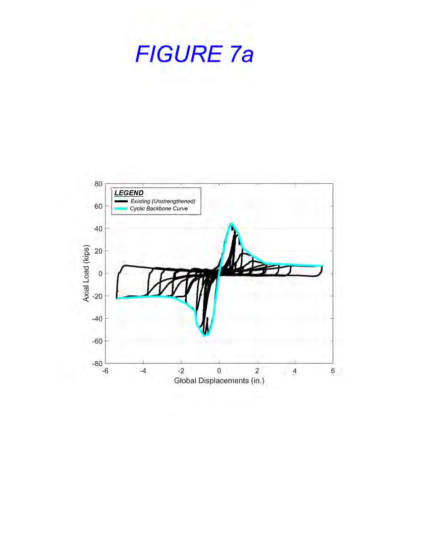
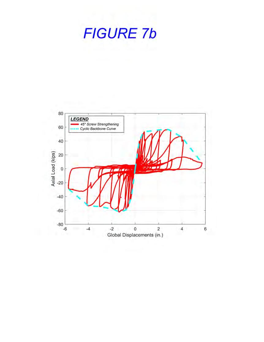
Simple-to-Use Wood Connection Health Monitoring System
Prior to testing various specimens, the wood connections were littered with random black dots drawn by hand with a permanent marker (any size and any shape was acceptable). Photographic still images were continuously taken throughout the duration of testing by a Cannon 6D camera that had been calibrated for lens distortion by a checkerboard
Figure 8. Shown are cyclic force-deformation comparisons of example split ring connections: unstrengthened (left) vs. 45° screw strengthening (right).
concept. Each digital image consisted of 20.2 mega-pixels, and by using Matlab (MathWorks) each pixel was then evaluated per its RGB color distribution. This allowed the centroid of each black dot to be determined and tracked throughout testing. The vector representing a distance between any of the dots in a 2D plane was then calculated, thereby providing a relative displacement or strain field across the specimen that was correlated to the measured axial load. This method allowed the team to discover and track wood cracks as small as 0.007 inches (0.18 mm) and larger simply through a series of photographic images (Figure 9). Since the process turned out to be simple and precise, KPFF installed numerous tracking dots (colored thumb tacks to preserve the historic nature of the hangar wood) within the MFA hangars that function as a passive health monitoring system. Readily available commercial products and software use similar techniques presented here. However, KPFF recommends exploring crack detection first through day-to-day software used in practicing firms, such as Matlab or Microsoft Office VBA, and a camera.
Conclusion
Only a portion of the experimental results and health monitoring system are presented here. The proposed screw repair and strengthening concept has been approved by NASA through the Alternate Means or Methods of Construction (AMMC) process. To date, thousands of fully threaded screws have been installed in both hangars H2 and H3 to repair or strengthen existing wood connections that well exceed ASCE 41-13 S-3 performance objective, along with ASCE 7-10 site-specific wind demands (Figure 10). The experimental testing program and developed screw strengthening concepts proved to be quite beneficial for project budget and to enhance the strength and ductility of the hangars when subject to wind and seismic hazards. We look forward to these strengthening measures and the health monitoring system to be applied to the renovation or new design of other timber structures. ■
Full references are included in the online version of the article at STRUCTUREmag.org .
Kenneth Ogorzalek, PE, SE, is an Associate at KPFF in San Francisco, CA, and specializes in Performance Based Design and Resiliency of new and existing buildings in high-seismic regions. (kenneth.ogorzalek@kpff.com)
Blake Dilsworth, PE, SE, is the Managing Principal for KPFF’s San Francisco office and leads the structural design and management of many of their highest profile projects, including dozens of Design/Build and Integrated Project Delivery (IPD) projects. (blake.dilsworth@kpff.com)
Shakhzod Takhirov, Ph.D, PE, is Director of Operations (Structures Lab and Center for Smart Infrastructure) at the University of California at Berkeley and has extensive expertise in structural testing and structural health monitoring. (takhirov@berkeley.edu)
KPFF is the SEOR for the renovation of all three hangars at MFA and hasve been work ing on them for more than a decade. The team would like to thank CBRE Director of Project Management, Alex Saleh P.E., for his project oversight, Dr. Ben Brungraber and Dr. Richard Schmidt from Fire Tower Engineered Timber (FTET) for their continuous peer review during the experimental testing program, Power Engineering Construction for fabricating all wood connection specimens, the personnel at the Structures Laboratory, University of California at Berkeley for conducting the experimental testing, and all other members of the design team.
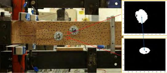
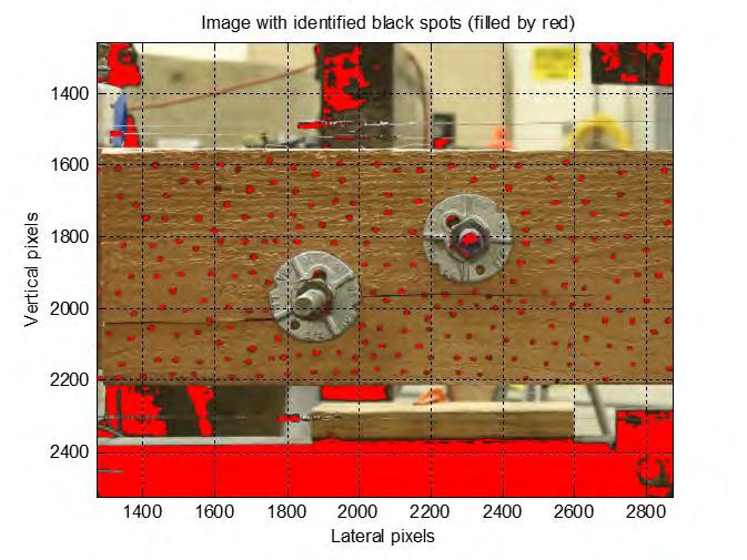
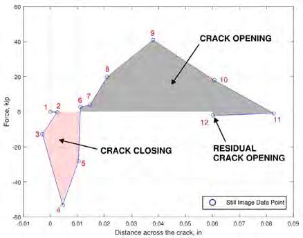
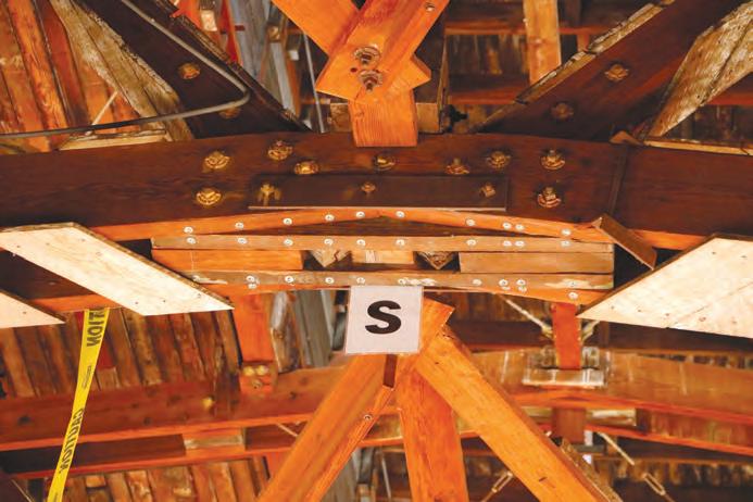
MAY 2024 35
Figure 9. In the health monitoring system, a typical photographic image (top) shows tracking dots. The tracking dots are identified in Matlab (middle) and a corresponding plot (above) shows crack detection and movement between the example tracking dots.
Figure 10. Fully threaded screws and washers are installed in the MFA hangars at arch truss panel points.

Modern Meets Historic
How innovative strengthening techniques saved the historic terra cotta flat-tile-arch floor structure of an iconic landmark. By
Michael D. Zajac, PE, LEED AP
Project Team
Structural Engineer of Record: Simpson Gumpertz & Heger, Washington, D.C.
Project Architect: Bowie Gridley Architects (now part of DLR Group), Washington, D.C.
Owner: DC Department of General Services, Washington, D.C.
General Contractor: STRUC’TUR’AL, Elkridge, Maryland
Designed by the firm of Cope and Stewardson in the American Beaux Arts style and dedicated as the District Building in 1908, the John A. Wilson Building currently serves as the city hall of Washington, D.C. The building is prominently situated along the south side of D.C.’s Pennsylvania Avenue corridor between the U.S. Capitol Building and the White House.
STRUCTURE magazine 36
Photo by Marvin Bowser, iStock
The structure of the Wilson Building is among early examples of so-called “fireproof” construction in Washington, which became standard practice for large commercial and important buildings following several disastrous fires in other cities around the turn of the 20th century. The structural floor systems were designed and constructed utilizing structural flat-tile-arch construction, which consisted of open-cell clay tile masonry unit blocks placed on temporary formwork and mortared into place. A lightweight cinder concrete topping slab was then placed, followed by sand-set terrazzo flooring, and a plaster ceiling finish along the underside. Although considered archaic compared to today’s construction materials and practices, such construction was common during the late 19th and early 20th century for commercial structures due to its fire resistance, lightweight, and shallow depth. At the Wilson Building, wrought iron beams were specified to support the clay tile structure of the office suites at each floor; the flat tile arches of the east and west corridors of the building bears upon the brick masonry corridor walls.
Problem Discovered
While visiting the building to investigate an unrelated structural scope item, engineers from Simpson Gumpertz & Heger (SGH) noted an uncharacteristic sag of several corridor floors, most notably on the 5th floor of the building. SGH noted subtle hairline cracking patterns in the plaster ceiling finish at the underside of the sagging slabs running parallel with and located approximately at the centerline of the corridor. At the south ends of each corridor, above an acoustic dropped ceiling, investigators found a prominent crack approximately 1-inch wide extending nearly the full length of the suspended ceiling area.
Cause of Damage
In order to determine the cause of the noted damage, SGH began researching various structural clay tile reference sources. Discoveries indicated that structural clay tile floor systems were specified by first taking into consideration the overall span of the floor system followed by determining the required load capacity, then a minimum clay tile depth was selected to satisfy the load and span requirement. Although significant redundancy and safety factors (sometimes as high as 7) are associated with structural clay tile floor assemblies, the team discovered that structural clay tile design guides and specifications at the time generally did not recommend 12-inch deep clay tile for spans exceeding 8 feet regardless of required load capacity. The corridor widths at the Wilson Building are on the order of 10 feet. Another factor which likely contributed to the damage relates to the August 23, 2011, earthquake experienced in the region. Although the characteristic corridor floor damages were observed at five of the six corridor floors framed with structural clay tiles, the most pronounced floor sag was observed at the top (5th) floor corridor slabs, where 1-1/2 inches of slab deflection was measured. Similar to other heavy stone masonry structures in the region, including the Washington Monument and Washington National Cathedral, the Wilson Building may have experienced significant movement and racking during the earthquake, disrupting the compressive force load path of the structural flat-tile-arch corridor floor systems. No information was available regarding the condition of the corridor floors prior to the August 2011 earthquake event.
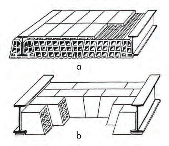
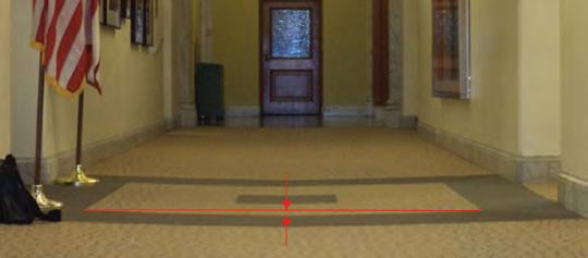
Conventional Repair Solutions Considered
To address the structural damage to the clay tile floor structure, the following conventional structural repair options were considered. Option 1: Removal and Replacement. This option included full demolition of structural clay tile floor slabs followed by replacement with either new cast-in-place reinforced concrete floor slab construction, or new composite slab on metal deck construction. This solution would have required vacating large areas of the building for an extended period. In addition, the historic plaster crown molding would have been lost.
Option 2: Reinforcement. This option was characterized by installing a new supplementary structure beneath the existing structural clay tile floor system. Such a structural system could have consisted of a steel beam framework supported on the masonry bearing walls of the corridor and shimmed tight to the underside of the existing clay tile floor assembly above, or installation of a new concrete slab directly beneath the clay tile floor system. The new concrete construction could have been engineered to carry the dead loads of the original floor slab, as well as the code-prescribed superimposed live loads. Similar to Option 1, this repair had the convenience of straightforward and conventional engineering, detailing and construction, but would not necessarily have required vacating various floors of the building during construction. However, the historic plaster crown molding would be lost.
MAY 2024 37
Figure 2. Typical structural clay tile flat arch floor construction is depicted. Source: “Structural Analysis of Historic Buildings” Rabun, 2000.
Figure 3. Typical sagging of the building’s corridor floor slab, shown here with the red line, measured approximately 1-1/2 inches. Photo copyright SGH.
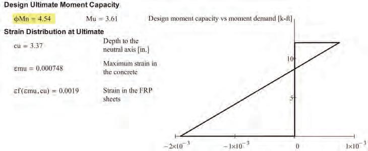
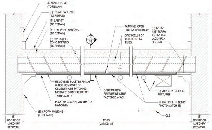
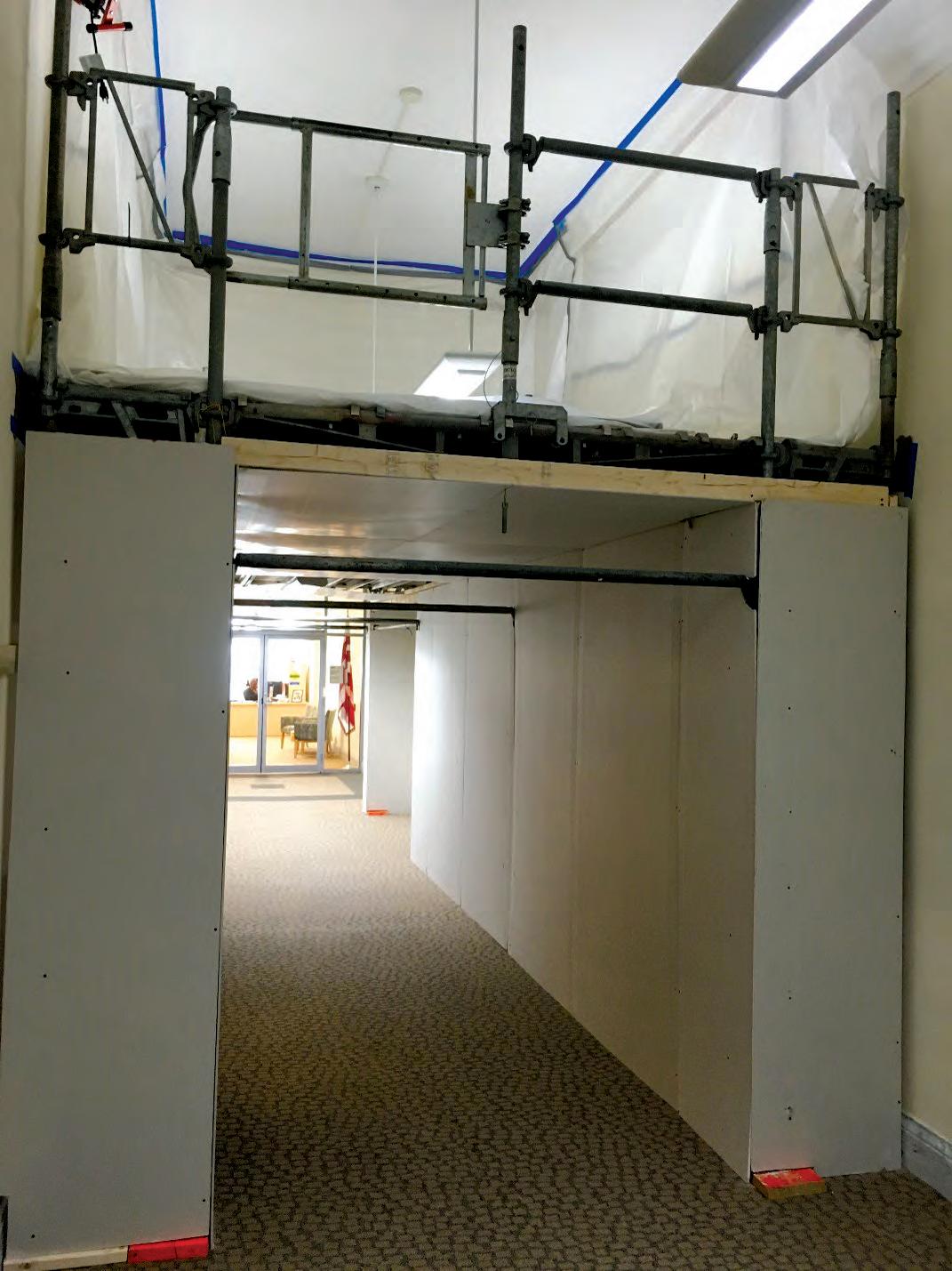
The Modern-Day Solution
Given the cost, disruption, and loss of historic fabric associated with the conventional repair options, the design team elected to consider a carbon fiber reinforced polymer (CFRP) reinforcement solution. CFRP has been commonly associated with successful repair and strengthening of concrete structures for many years, but little information exists with respect to reinforcing structural clay tile flat arch floor systems. Whereas the original structural clay tile relied upon compressive forces offered by flat tile arch construction to carry dead and live loads, a CFRP system would change existing floor structure into a one-way reinforced clay tile and concrete slab, with tension forces carried by the CFRP bonded along the underside of the structural clay tile, and the concrete topping serving as the compression block. Since there was no indication of shear distress or shear failure of the slab-towall bearing, the CFRP could stop short of the bearing points, preserving the historic plaster crown molding.
The existing structural clay tile flat arch floors consisted of multiple parallel rows of 12-inch square by 12-inch deep clay tile units. The repair specified a continuous strip of 6-inchwide CFRP bonded along the centerline of each 12-inch-wide row of clay tiles.
The CFRP system offered the following benefits:
1. O ccupancy: Vacating the spaces of the building served by the corridors would not be required.
2. Cost savings: Compared to the conventional demolish-and-replace repair options, CFRP would offer significant savings.
3. Retention of historic fabric: The existing structural clay tile floor system, original terrazzo floor finish, and historic plaster crown molding could all remain.
Although the CFRP-reinforced terra cotta floor slab construction is not part of any fire-rated UL assembly, the design assumed that the existing condition of the damaged floor assembly was suitable to support the self-weight of the existing floor system in addition to nominal live loads.
Execution
The repair work began with installation of temporary wood planking work platforms
STRUCTURE 38
Figure 4a. This illustration depicts moment capacity comparison and strain diagram of reinforced condition.
Figure 4b. A floor section with CFRP repair detail is shown.
Figure 5. Temporary shoring frames are wrapped with temporary finish on the work platform above a corridor. Photo copyright SGH.
integrated with conventional metal shoring frames and supplemental shore posts extending down multiple floors to the basement slab on grade. The generous floorto-ceiling heights of the building permitted the shoring frame system to incorporate the elevated work platforms above each corridor so the workspace could be fully enclosed to allow the corridors to remain open for daily use and egress. In addition, installation of the shoring system utilized screw jacks with wood blocking to engage the vertical shore posts into the underside of each slab above, installed in “snug tight” manner. This installation technique was critical to avoid heaving of the slab and to maintain the compression load paths of the structural clay tile arch floor system. Temporary corridor lighting was installed along the underside of the work platform, along with protective barriers to prevent building occupants from accessing the work areas.
With access to the work area completed, the repair team began executing plaster removal by mechanical tools with careful means and methods to prevent significant damage and abrasions to the base clay tiles. The substrate was then cleaned and prepared to receive the initial epoxy resin base coat followed by continuous CFRP reinforcement strips. The project included testing mockups and pull tests to confirm that the bond between the epoxy resin and clay tile substrate was sufficient to develop the CFRP. All mockups successfully satisfied the project specification.
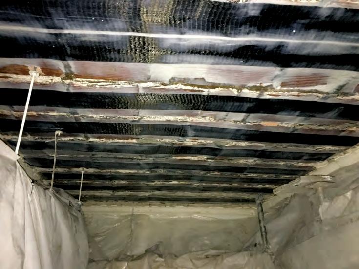
new plaster finish followed by a finish coat of paint was installed. In order to ensure proper mechanical bond of the plaster coating to the repaired substrate, the CFRP reinforcement was coated with a secondary layer of epoxy embedded with sand. Adhesion testing of the new plaster coat on the cured epoxy repair material indicated a bond even better than the original plaster coating on the underside of the original structural clay tile floor system.
Where existing features such as hanging fixtures and electrical items prevented centering of the CFRP reinforcement along the centerline of the clay tile row, the CFRP was offset as field conditions permitted. At areas where the clay tile was extensively damaged, CFRP strips were placed side by side to provide full coverage of the underside of the clay tile floor slab. No attempts were made to lift the slab back into a more level profile as the structural engineering team anticipated difficulty achieving success and the risk of opening tension cracking in the concrete topping and disrupting the compression block load path, in addition to damaging the original historic terrazzo floor finish, was high. In addition, no leveling compounds were placed on top of the slab. The original terrazzo floor finish remained present and unaltered under the existing carpet finish.
As is often common with historic structural clay tile floor systems, several unforeseen conditions arose during execution of the work, including discovery of broken tiles and miscellaneous voids along the underside of the floor slab. Since the CFRP system required a continuous substrate along the underside of the floor slab, the the voids of broken clay tiles were infilled with a cementitious overhead patching mortar prior to application of the epoxy coating and CFRP reinforcement.
Final Finish
Two final finishes were specified as part of the work.
Type 1: At areas of exposed plaster ceiling and crown molding, a
Type 2: At the suspended ceiling areas, much of the original plaster ceiling had already been penetrated with various mechanical and electrical connections prior to execution of the work. Following the completion of the work, these areas would remain concealed above the suspended ceiling bulkhead below. Therefore, the owner elected not to reapply plaster finish at the concealed condition. Instead, a water-based intumescent coating was applied to provide a layer of fire protection for the CFRP. In order to protect the CFRP strips from future damage during future mechanical/electrical/plumbing work, “DO NOT CUT” stenciling was applied.
Closing
Applying a strengthening technique usually associated with concrete structures ultimately resulted in a clever and successful solution that saved time, money, and historic building fabric while allowing the building to remain occupied during construction, with no obvious visible changes to the spaces at the completion of the project. ■
Michael D. Zajac, PE, LEED AP, is a Senior Project Manager in the Washington, D.C., office of Simpson Gumpertz & Heger. (mdzajac@sgh.com)
MAY 2024 39
Figure 6. CFRP reinforcement strips installed is shown. Photo copyright SGH.
Wood Floor Truss Collapse: A Case Study
The real reason for the failure of a clubhouse floor was not the dancing.
By Scott D. Coffman, PE
The Woodlands at Clemson clubhouse floor collapsed in the early Sunday morning hours of October 20, 2018, injuring several individuals who had gathered for an annual homecoming weekend party. Several engineers and media outlets concluded that the rhythmic jumping (i.e., dancing) by a significant number of individuals was the cause of the floor collapse. However, two structural engineers who investigated the floor collapse found evidence that improper metal plate connected wood truss design and fabrication were more likely the proximate cause. The rhythmic dancing on the floor exposed a truss deficiency that prevented the truss system from supporting code-prescribed loads.
Building Code
The clubhouse was a wood-framed, two-level structure identified as an A-3 Assembly on the Certificate of Occupancy. The applicable building code for the building was the 2000 International Building Code (IBC). The IBC specifically associated dance halls to the A-3 Assembly and prescribed a 100 pound per square foot (psf) design live load. The “oldtime” dance halls probably did not consider rhythmic jumping; however, the prescribed 100 psf static load appeared reasonable for a community building in an apartment building complex.
The local Fire Marshal limited the maximum number of occupants to 135 for the main floor level based on documents made available during the investigation. The IBC assigned a maximum of 5 square feet per occupant for standing space in an Assembly space. The collapsed floor area measured approximately 20 feet x 30 feet to imply at least 120 individuals could congregate in the area.
Collapsed Floor Observations
The collapsed floor framing consisted of 24-inch-deep metal plate connected wood trusses spaced 16 inches on center with a measured length of approximately 20 feet-9 inches. The chord and web lumber grades were noted, and plate sizes were measured. The truss lumber failure locations were predominately limited to the truss end that intersected the stair wall (Figure 1). On the opposite end, the floor framing rotated and fell against the exterior wall with the broken ends resting on the lower-level floor. The truss bottom chord (tension member) in the center one-third of the span did not appear to be damaged and the metal truss plates were fully embedded. The truss evaluation was made to address three specific questions:
• Was the truss designed for the code-prescribed 100 psf live load?
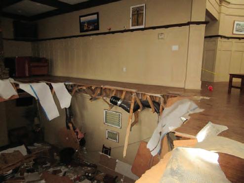
• Is a 100 psf live load sufficient to support a rhythmic dancing dynamic load?
• Why did the floor collapse?
The Truss Plate Institute’s 1995 Edition of the National Design Standard for Metal Plate Connected Wood Truss Construction (TPI) as referenced in the 2000 IBC was used to collect data and perform an analysis of the floor truss component.
Initial Truss Analysis
The wood truss design drawings were requested but not available. The truss midspan bottom chord tension stress was calculated for a 115 psf total load and compared to the published allowable tension design value (Ft) for the noted truss chord's lumber grade. (The 115 psf total load is the sum of a 100 psf live load and the historical truss industry common practice of a total 15 psf top and bottom chord dead load). The wood chord member was found to be structurally sufficient for the calculated tension force. Additionally, metal connector plates at truss panel points were found to have sufficient coverage for the 115 psf total load. Therefore, it was concluded that the truss was originally designed for the code-prescribed 100 psf live load.
Dynamic Truss Analysis
There are no wood truss industry design guidelines available to evaluate dynamic loads for a group of individuals who perform rhythmic dancing or jumping on a floor. Research revealed studies that reported an amplification factor on a person’s body weight as they ascended or descended a staircase. A 1998 study by Stuart C. Kerr found an enhancement factor of 4 times the body weight for a large group (greater than 25 people) ascending or descending a flexible staircase. With this research information, the wood truss ultimate tension chord capacity was used to evaluate the code-prescribed 100 psf design load for dynamic loads.
The published Ft was increased by the 2.1 general adjustment factor to approximate the lumber ultimate tension strength value. (The 2.1 factor includes a 1.6 factor for duration of load the author considered acceptable for rhythmic dancing or jumping). It was found the truss could support a 255 psf maximum uniform static live load before the truss bottom chord might break. Additionally, the dynamic floor capacity was investigated using the 255 psf live load and 20 feet x 30 feet floor area. It was determined that 170 individuals could be on the 20 feet x 30 feet floor area using a 225 pound per person weight and enhancement/amplification
STRUCTURE magazine 40
Figure 1. The truss lumber failure locations were predominately limited to the truss end that intersected the stair wall.
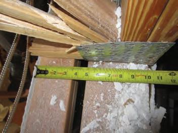

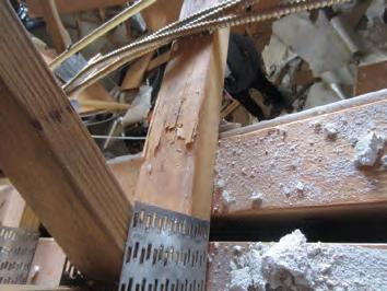
factor of 4. (The 170 occupants exceeds the 120 people determined using the 5 square feet per person IBC limit.) Based on the analysis, a wood truss floor system designed to a code prescribed 100 psf static live load is anticipated to perform without failure/collapse when subjected to dynamic loads by the occupants.
Subsequent to our initial dynamic floor analysis, M.A. Broers et al. (2021) published Residential Floor Failures from Dynamic Occupant Loading that gives a procedure to evaluate the dynamic impact of jumping on a wood floor. The study found amplification factors ranged between 1.55 and 3.2 and recommended that a 2.5 factor be applied to the static code-prescribed live load. The author’s analysis and conclusions were consistent with the Broers study. Therefore, a wood truss floor system designed for a 100 psf static live load should not have failed when subjected to dynamic loading.
Improper Truss Bearing Design Caused Floor Truss Failure
The investigation focused on the truss end bearing condition when it became evident a floor truss system designed to a 100 psf live load should be able to support dynamic loads. The source of the truss failure appeared to originate at the interior stair wall. The 10-inch-wide double stud wall consisted of a 2x6 stud adjacent to the stairs, a 1-inch air space, and 2x4 stud wall that was positioned within the first bottom chord truss panel (Figure 2). As load was applied, the primary truss bearing support became the 2x4 plates/wall instead of the 2x6 wall located below the double vertical and diagonal web at the truss end. The absence of a truss web element above the 2x4 wall changed the intended load path and caused the bottom chord to bend until breaking which precipitated the floor collapse when dynamically loaded. The metal connector plate buckling or tooth “back-out” was a result of high localized forces (Figure 3). The splintered top edge of the truss bottom chord at the inside edge of the 2x4 wall identified the de facto primary truss support locations (Figure 4). The buckled metal connector plate and wood fracture at the interior face of the wall are signs of improper design of the truss bearing.
The truss industry publishes typical floor truss bottom chord bearing details and four examples are depicted in Figure 5. In each condition, a minimum of one vertical web and a portion of the metal connector plate is located immediately above the bearing wall. For this truss failure, the webs and metal connector plates were absent above the 2x4
wall that became the primary truss support even though the 2x6 wall was solely intended to serve that purpose.
The truss bottom chord capacity at the inside edge of the 2x4 wall was investigated to determine the approximate maximum uniform design load the truss could support. The bending stress was calculated and compared to the published allowable stress design bending design value (Fb) that was increased for a ten-minute load duration factor (CD = 1.6), flat use factor (Cfu = 1.1), and repetitive member factor (Cr = 1.15). The tension component that would have reduced the truss design capacity a minimal amount was neglected. The truss uniform design live load was calculated to be 50 psf or half of the original 100 psf live load. Therefore, the wall positioned below the first bottom chord truss panel where webs were absent was the reason the truss failed. The rhythmic dancing exposed the truss's weak point from the improper design. At least one web should have been located over the 2x4 portion of the double stud wall. All webs were located over the 2x6 portion of the double stud wall which permitted the bottom chord to fail in bending as the truss was loaded to less than design capacity.
Conclusion
The code prescribed design live load of 100 psf was found to be sufficient for static and dynamic live loads when metal plate connected wood trusses are designed and fabricated properly. The rhythmic jumping (i.e., dancing) by a significant number of individuals as cited by engineers and media outlets was not the primary reason for the Woodlands at Clemson clubhouse floor collapse. A truss bearing design error reduced the floor truss capacity by 50% and the dynamic load exposed the truss design deficiency. The absence of a truss web above the inner truss bearing location created by a double wall placed the bottom chord in bending and tension. This configuration changed the load path which exceeded the lumber capacity and resulted in failure when subjected to a less-than-codeprescribed load. ■
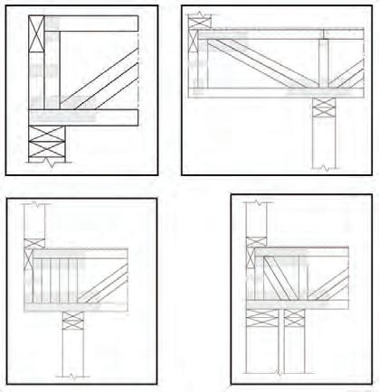
Full references are included in the online version of the article at STRUCTUREmag.org .
Scott D. Coffman, PE is a Senior Engineer with REI Engineers, Inc. in Westminster, South Carolina, that provides forensic engineering services. He can be reached at scoffman@reiengineers.com.
MAY 2024 41
Figure 2. The 10-inch-wide double stud wall consisted of a 2x6 stud adjacent to the stairs, a 1-inch air space, and 2x4 stud wall that was positioned within the first bottom chord truss panel.
Figure 3. The metal connector plate buckling or tooth “backout” was a result of high localized forces.
Figure 4. The splintered top edge of the truss bottom chord at the inside edge of the 2x4 wall identified the de facto primary truss support locations.
Figure 5. Four examples of typical floor truss bottom chord bearing deatails are depicted.


No matter how hard the job gets, JLG® is built to help you stand tough through it all. High-capacity telehandlers are engineered to weather the worst while delivering state-of-the-art tech including Smart Load technology that keeps focus up and downtime down. Never settle. Leave your mark. LEAVEYOURMARKWITHJLG.COM YOUR WORK STANDS THE TEST OF TIME. YOUR EQUIPMENT SHOULD TOO.
code UPDATES
2024 IBC Significant Structural Changes
Wood (IBC Chapter 23)—Part 7
By John “Buddy” Showalter, PE, and Sandra Hyde, PE
This multi-part series discusses significant structural changes to the 2024 International Building Code (IBC) by the International Code Council (ICC). This article includes an overview of changes to IBC Chapter 23 on wood. Only a portion of the chapter’s total number of code changes is discussed in this article. More information on the code changes can be found in the 2024 Significant Changes to the International Building Code available from ICC.
Referenced Standards
Table 1 provides a list of standards that are newly referenced or updated in the 2024 IBC.
Wood Structural Panel Wall Sheathing
IBC Table 2304.6.1 provides requirements and limitations for wood structural panels (WSP) used as exterior wall sheathing when resisting wind pressure (Figure 1). For a given wind speed and exposure category, the table gives the minimum nail size, WSP span rating, panel thickness, stud spacing, and nailing schedule. The limitations of the table are that the building must be enclosed, the mean roof height must be not greater than 30 feet, and the topographic factor must be equal to 1.0.
Change Significance: Tabulated values are modified for basic wind
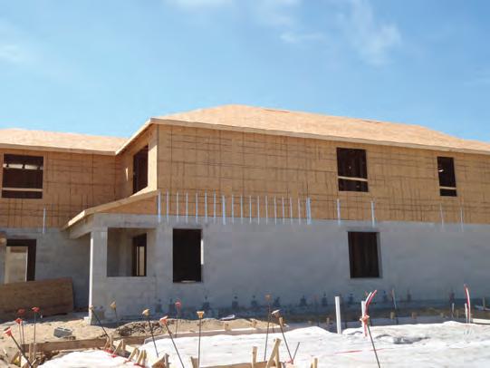
Table 2304.6.1 Maximum Allowable Stress Design Basic Wind Speed, Vasd V, Permitted for Wood Structural Panel Wall Sheathing Used to Resist Wind Pressures a, b, c
speeds to be consistent with ASCE 7-22 Minimum Design Loads and Associated Criteria for Buildings and Other Structures. This change updates the tabulated values from allowable stress design wind speeds (Vasd) to basic wind speeds (V) for consistency with ASCE 7-22. When developing these modifications, stud and panel capacities, nail withdrawal resistance, and nail-head pull-through capacities were evaluated in the same manner as the previous table, resulting in comparable design requirements as the wind speeds are soft-converted from Vasd values per IBC Section 1609.3.1. The tabulated wind speeds are also consistent with those in 2021 International Residential Code (IRC) Table R602.3(3). Footnote “b” was updated to reference ASCE 7 Section 30.4. Since the revised table reflects basic wind speeds, the previous text in footnote “d” is no longer required but is replaced by a new note. The new footnote “d” text recognizes the minimum specific gravity basis of 0.42 for the WSP fastener spacing and provides a prescriptive option (i.e., multiply spacing by 0.67) for framing species with lower specific gravity down to a specific gravity equal to 0.35. Engineered design of the WSP fasteners is required when the specific gravity is less than 0.35 for the lumber species used for wall framing.
b. The table is based on wind pressures acting toward and away from building surfaces in accordance with Section 30.7 4 of ASCE 7. Lateral requirements shall be in accordance with Section 2305 or 2308. d. Vasd shall be determined in accordance with Section 1609.3.1. Where the specific gravity of the wood species used for wall framing is greater than or equal to 0.35 but less than 0.42 in accordance with AWC NDS, nail spacing in the field of the panel shall be multiplied by 0.67. Where the specific gravity of the wood species used for wall framing is less than 0.35, fastening of the wall sheathing shall be designed in accordance with AWC NDS.
(Footnotes “a” and “c” did not change and are not shown for brevity)
Fire Protection of Connections
IBC Section 2304.10.1 provides two options for demonstrating compliance for the protection of connections in Types IV-A, IV-B, and IV-C construction: a testing option
MAY 2024 43
Minimum Nail Minimum Wood Structural Panel Span Rating Minimum Nominal Panel Thickness (inches) Maximum Wall Stud Spacing (inches) Panel Nail Spacing Maximum Allowable Stress Design Basic Wind Speed, Vasdd (mph) Size Penetration (inches) Edges (inches o.c.) Field (inches o.c.) Wind Exposure Category B C D 6d Common (2.0" × 0.113") 1.5 24/0 3/8 16 6 12 d 140 110 115 90 110 85 24/16 7/16 16 6 12 d 150 110 125 100 115 90 6 d 190 150 160 125 150 110 8d Common (2.5" × 0.131") 1.75 24/16 7/16 16 6 12 d 170 130 140 110 135 105 6 d 190 150 160 125 150 110 24 6 12 d 140 110 115 90 110 85 6 d 140 110 115 90 110 85
Figure 1. Wood structural panel wall sheathing (courtesy Norbord [David Lewis])
and a calculation option. The provisions do not apply to connections in heavy timber (IV-HT) construction, because heavy timber structural members do not have a prescribed fire-resistance rating. Connections in Type IV-A, IV-B and IV-C construction are required to have fire protection for the time associated with fire protection of the primary structural frame members (Figure 2).
American Wood Council
ANSI/AWC NDS—2024 National Design Specification (NDS) for Wood Construction—with NDS Supplement
ANSI/AWC WFCM—2024 Wood Frame Construction Manual for Oneand Two-Family Dwellings
AWC STJR—2024 Span Tables for Joists and Rafters
ASTM
E2768 -11(2018) Standard Test Method for Extended Duration Surface Burning Characteristics of Building Materials (30 min Tunnel Test)
D8223-19 Standard Practice for Evaluation of Fire-Retardant Treated Laminated Veneer Lumber
A641/A641M-19 Specification for Zinc-coated (Galvanized) Carbon Steel Wire
American Society of Agricultural and Biological Engineers
EP 484.3 DEC2017 (R2022) Diaphragm Design of Metal-clad, Woodframe Rectangular Buildings
EP 486.3 SEP2017 (R2021) Shallow-post and Pier Foundation Design
EP 559.1 AUG2010 (R2019) Design Requirements and Bending Properties for Mechanically Laminated Wood Assemblies
APA – The Engineered Wood Association
ANSI/APA A190.1—2022 Product Standard for Structural Glued Laminated Timber
ANSI/APA PRR 410—2021 Standard for Performance-Rated Engineered Wood Rim Boards
APA PDS Supplement 1—23 Design and Fabrication of Plywood Curved Panels
APA PDS Supplement 2—23 Design and Fabrication of Plywood-lumber Beams
APA PDS Supplement 3—23 Design and Fabrication of Plywood Stressed-skin Panels
APA PDS Supplement 4—23 Design and Fabrication of Plywood Sandwich Panels
APA PDS Supplement 5—23 Design and Fabrication of All-plywood Beams
APA T300—23 Glulam Connection Details
APA X440—23 Product Guide: Glulam
APA X450—23 Glulam in Residential Building—Construction Guide Truss Plate Institute
ANSI/TPI 1—2022 National Design Standard for Metal Plate Connected Wood Truss Construction West Coast Lumber Inspection Bureau
AITC 200—20 Manufacturing Quality Control Systems Manual for Structural Glued Laminated Timber
2304.10.1 Connection fire-resistance rating Fire protection of connections. Fire-resistance ratings for connections in Connections used with fire-resistance-rated members and in fire-resistance-rated assemblies of Type IV-A, IV-B or IV-C construction shall be protected for the time associated with the fire-resistance rating. Protection time shall be determined by one of the following:
1. Testing in accordance with Section 703.2 where the connection is part of the fire-resistance test.
2. Engineering analysis that demonstrates that the temperature rise at any portion of the connection is limited to an average temperature rise of 250°F (139°C), and a maximum temperature rise of 325°F (181°C), for a time corresponding to the required fire-resistance rating of the structural element being connected. For the purposes of this analysis, the connection includes connectors, fasteners and portions of wood members included in the structural design of the connection.
Change Significance: This change clarifies the code intent that connections are required to be protected for the time associated with the fire-resistance rating of members and assemblies as required by IBC Sections 704.2 for the primary structural frame.
However, IBC Section 704.2 does not require connections that join elements of the structural frame to be tested per ASTM E119 Standard Test Methods for Fire Tests of Building Construction and Materials or UL263 Fire Tests of Building Construction and Materials. The connections must only be protected with a material having the fire-resistance rating required for the structural members that they connect. It is neither practical nor possible to test connections in a standard fire test furnace since there is no capability to test large connections used to transfer gravity loads. In addition, neither ASTM E119 nor UL263 includes any provisions on how to test connections and assess their performance. See the May 2023 issue of STRUCTURE for more background on design for fire protection of mass timber connections.
Wood Shear Walls and Diaphragms
IBC Section 2305.1 references AWC’s Special Design Provisions for Wind and Seismic (SDPWS) for the design and construction of wood shear walls and wood diaphragms to resist wind, seismic, or other lateral loads.
2305.1 General. Structures using wood-frame shear walls or woodframe diaphragms to resist wind, or seismic or other lateral loads shall be designed and constructed in accordance with AWC SDPWS and the applicable provisions of Sections 2305, 2306 and 2307.
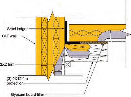
STRUCTURE magazine 44
Table 1. Standards Newly Referenced or Updated in the 2024 IBC
Figure 2. Fire protection of connections in Type IV-A, IV-B and IV-C construction
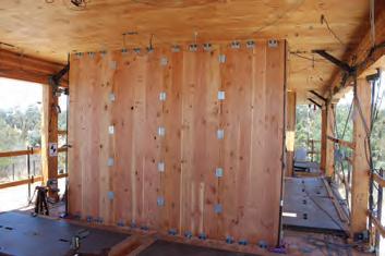
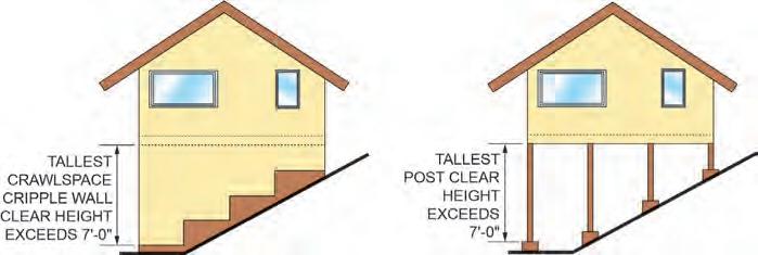
2305.1.2 Permanent load duration. Permanent loads are associated with permanent load duration in accordance with the ANSI/AWC NDS. For wood shear walls and wood diaphragms designed to resist lateral loads of permanent load duration only and that are not in combination with wind or seismic lateral loads, the design unit shear capacities shall be taken as the AWC SDPWS nominal unit shear capacities, multiplied by 0.2 for use with allowable stress design in Section 2306 and 0.3 for use with load and resistance factor design in Section 2307.
Change Significance: Terminology in IBC Section 2305.1 changes to use “wood shear walls” and “wood diaphragms” instead of “woodframe” shear walls and diaphragms. The terminology change is driven by the need to cover the design of both wood-frame and cross-laminated timber shear walls and diaphragms in the SDPWS (Figure 3).
Reference to the SDPWS is appropriate for the design of wood shear walls and diaphragms to resist wind and seismic loads, but for resistance to permanent lateral loads, such as soil loads in foundation design, the nominal unit shear capacities in SDPWS need further reduction to account for long-term effects. Permanent loads are associated with a permanent load duration factor (allowable stress design, ASD) or timeeffect factor (load and resistance factor design, LRFD) as defined by the NDS. IBC Section 2305.1.2 now requires the use of a 0.2 factor for ASD and a 0.3 factor for LFRD.
Hillside Light-frame Wood Construction
One of the most important aspects of prescriptive methods is meeting the restrictions and limitations required to use the method. The structures for which conventional light-frame wood construction is applicable are described in IBC Section 2308.2. For light-frame wood dwellings on steep hillsides, the typical assumption of floor loads transferring to braced wall panels based on the tributary area of a flexible wood floor may not provide adequate seismic performance (Figure 4). This building configuration was found to be vulnerable in the 1994 Northridge, California earthquake. Whether the earthquake motion occurs across the slope or perpendicular to the hill, seismic forces follow the stiffest load path to the uphill foundation, rather than distributing evenly to all braced wall panels as assumed in prescriptive IBC seismic wall bracing provisions.
CHAPTER 2 DEFINITIONS
CRIPPLE WALL CLEAR HEIGHT. The vertical height of a cripple wall from the top of the foundation to the underside of floor framing above.
2308.2 Limitations. Buildings are permitted to be constructed in accordance with the provisions of conventional light-frame construction, subject to the limitations in Sections 2308.2.1 through 2308.2.6 2308.2.7
(No changes to Sections 2308.2.1, 2308.2.2, 2308.2.4 and 2308.2.5. Changes to 2308.2.3 and 2308.2.6 not shown for brevity.)
2308.2.7 Hillside light-frame construction. Design in accordance
with Section 2308.3 shall be provided for the floor immediately above the cripple walls or post and beam systems and all structural elements and connections from this floor down to and including connections to the foundation and design of the foundation to transfer lateral loads from the framing above in buildings where all of the following apply:
1. The grade slope exceeds 1 unit vertical in 5 units horizontal where averaged across the full length of any side of the building.
2. The tallest cripple wall clear height exceeds 7 feet (2134 mm); or, where a post and beam system occurs at the building perimeter, the post and beam system tallest post clear height exceeds 7 feet (2134 m).
3. Of the total plan area below the lowest framed floor, whether open or enclosed, less than 50 percent is occupiable space having interior wall finishes conforming to Section 2304.7 or Chapter 25.
Exception: Light-frame buildings in which the lowest framed floor is supported directly on concrete or masonry walls over the full length of all sides except the downhill side of the building are exempt from this provision.
Change Significance: These new load path provisions provide a correlation between the prescriptive requirements of IBC Section 2308 and IRC Section R301.2.2.6 Item 8. The hillside requirement was added to the 2021 IRC with the intent of improving the seismic performance of hillside light-frame wood buildings. A related modification was also made to ASCE 7-22 to provide additional guidance to engineers designing these types of structures.
Wind Uplift
Wind loads (based on main wind force-resisting system pressures) can cause considerable uplift forces on roof framing. The uplift loads must be positively transferred into the structure below to resist the uplift (Figure 5).
2308.11.4 Wind uplift. The roof construction shall have rafter and truss ties to the wall below. Resultant uplift loads shall be transferred to the foundation using a continuous load path. The rafter or truss-towall connection shall comply with Tables 2304.10.2 and 2308.11.4.
Exception: The truss-to-wall connection shall be determined from the uplift forces as specified on the truss design drawings or as shown on the construction documents.
Change Significance: Changes to IBC Section 2308.11.4 (formerly 2308.7.5) and the corresponding table update roof-to-wall connection uplift loads to comply with the IBC-referenced standard ASCE 7-22. Tabulated wind uplift loads have been updated based on the basic wind speeds used in ASCE 7-22 (and ASCE 7-16) which match the required basic wind speeds of IBC Figures 1609.3(1) through 1609.3(4). (see the March 2024 issue of STRUCTURE on IBC Chapter 16 loads for more background)
Basic wind speeds are tabulated for 90-140 mph which provides values up to the maximum wind speed permitted in IBC Section 2308.2.4 for conventional light-frame construction. Uplift loads for Exposures C and D with an assumed mean roof height (MRH) of 33 feet are
MAY 2024 45
Figure 3. CLT shear wall
Figure 4. Cripple wall heights that trigger engineered design
also now tabulated eliminating the need for the table in Footnote “a”. A higher MRH will require engineering analysis for uplift connectors.
Uplift connection requirements now include the effects of 24-inch overhangs. Calculations are no longer required to determine the magnitude of the uplift loads by adding the overhang loads previously found in the table. While conservative, engineering analysis can be used to reduce uplift loads for roofs with shorter overhangs. Overhangs greater than 24 inches will require engineering analysis. A new exception is added to IBC Section 2308.11.4 to allow trussto-wall connections to be designed using either the loads on the truss design drawings or the construction documents. This new language is meant to be consistent with IRC Section R802.11.1 for truss uplift resistance.
Conclusion
Exposure C
Exposure D
a. The uplift connection requirements are based on a 33 30-foot mean roof height. located in Exposure B. For Exposure C or D and for other mean roof heights, multiply the loads by the following adjustment coefficients:
Structural engineers should be aware of significant structural changes in the 2024 IBC Chapter 23 on wood. Tabulated values are modified for basic wind speeds to be consistent with ASCE 7-22. New footnote text provides a prescriptive option for framing species with a specific gravity lower than 0.42. Connections in Type IV-A, IV-B and IV-C construction are required to have fire protection for the time associated with fire protection of the primary structural frame. Design requirements for wood-frame and cross-laminated timber shear walls and diaphragms are added. For resistance to permanent lateral loads, such as soil loads in foundation design, capacity reductions are added to account for long-term effects in nominal unit shear capacities. New load path requirements are intended to improve the seismic performance of hillside light-frame wood buildings. Roof-to-wall connection uplift loads are updated to be consistent with ASCE 7-22. ■
d. The uplift connection requirements do not account for include the effects of 24" overhangs. The magnitude of the loads shall be increased by adding the overhang loads found in the table. The overhang loads are based on framing spaced 24 inches on center. The overhang loads given shall be multiplied by the overhang projection and added to the roof uplift value in the table.
e. The uplift connection requirements are based on wind loading on end zones as defined in Figure 28.3-1 of ASCE 7. Connection loads for connections located a distance of 20 percent of the least horizontal dimension of the building from the corner of the building are permitted to be reduced by multiplying the table connection value by 0.75 and multiplying the overhang load by 0.8
g. Interpolation is permitted for intermediate values of Vasd and roof spans.
h. The rated capacity of approved tie-down devices is permitted to include up to a 60-percent increase for wind effects where allowed by material specifications. The required rating of approved uplift connectors is based on allowable stress design loads.
i. Vasd shall be determined in accordance with Section 1609.3.1 (Footnotes “b”, “c” and “f” did not change and are not shown for brevity)
John “Buddy” Showalter, PE, M. ASCE, M. NCSEA (bshowalter@iccsafe.org) is a Senior Staff Engineer and Sandra Hyde, PE, M. ASCE, M. NCSEA (shyde@iccsafe.org) is Managing Director of ICC’s Consulting Group.
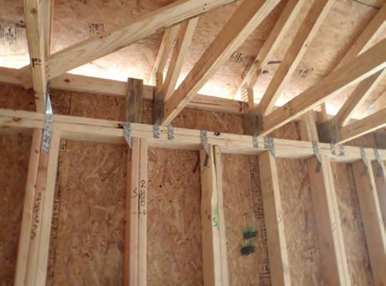
STRUCTURE magazine 46
Nominal Design Basic Wind Speed,
Roof Span (feet) Overhangs (pounds/ feet)d 12 20 24 28 32 36 40 Exposure B 85 90 -72 -64 -120 -85 -145 -96 -169 -107 -193 -117 -217 -128 -241 -139 -38.55 90 100 -91 -102 -151 -139 -181 -158 -212 -177 -242 -195 -272 -214 -302 -233 -43.22 100 110 -131 -144 -281 -199 -262 -226 -305 -254 -349 -282 -393 -310 -436 -338 -53.36 110 120 -175 -190 -292 -265 -351 -302 -409 -339 -467 -377 -526 -414 -584 -452 -64.56 130 -240 -335 -382 -431 -479 -528 -576 140 -294 -411 -470 -530 -590 -650 -710
Vasd
90 -126 -175 -199 -223 -247 -272 -296 100 -179 -250 -285 -320 -356 -391 -426 110 -238 -332 -380 -428 -476 -525 -573 120 -302 -424 -485 -547 -608 -669 -731 130 -371 -521 -597 -674 -751 -828 -904 140 -446 -628 -719 -812 -904 -997 -1090
90 -166 -232 -265 -298 -311 -364 -396 100 -229 -321 -367 -413 -459 -505 -551 110 -298 -418 -478 -539 -601 -662 -723 120 -373 -526 -603 -679 -756 -833 -910 130 -455 -641 -734 -829 -924 -1020 -1114 140 -544 -767 -878 -992 -1106 -1220 -1333 Table 2308.11.4 Required Rating of Approved Uplift Connectors (pounds)a, b, c, d, e, f, g, h
Mean Roof Height (feet) EXPOSURE 15 20 25 30 35 40 45 50 55 60 B 1.00 1.00 1.00 1.00 1.05 1.09 1.12 1.16 1.19 1.22 C 1.21 1.29 1.35 1.40 1.45 1.49 1.53 1.56 1.59 1.62 D 1.47 1.55 1.61 1.66 1.70 1.74 1.78 1.81 1.84 1.87
Figure 5. Roof truss-to-wall uplift connectors (courtesy Norbord [David Lewis])
structural RESILIENCE
New Solution Needed Following Flooding in Historic Office Complex Buildings
A renovation project found success with a newly developed mat foundation system.
By Russ Miller-Johnson, PE, SE
The State Office Complex historic buildings in Waterbury, Vermont, were devastated by Tropical Storm Irene’s 2011 flooding. The fully inundated partial basement levels, used for office, storage, and mechanical system functions, were a complete property loss with extensive clean-up and remediation to remove alluvial debris and incipient mold. The mandated renovation project selected 13 of the original 20 buildings for preservation and resilient improvements requiring the interconnected basements to be “flood-proofed” for 500-year event flood criteria. A range of both dry and wet floodproofing options were studied.
The design team developed a stressed-skin type “sandwich” mat foundation system, comprised of steel fiber-reinforced concrete outer layers with a lightweight flowable cellular concrete fill (FCCF) center, for eliminating basement level flooding. The design balanced the settlement resulting from the added infill weight with the competing hydrostatic uplift effects due to the basement level being below the design flood elevation. The system significantly reduced the difficulties of construction in existing basements and met the owner and construction manager’s budget and schedule constraints. Since 2014, the installation has not seen settlement distress; and in July 2023 it withstood flooded conditions approaching the design flood elevation.
The 2011 flooding first reached the partial basement levels by surface flow into window well and utility passages at the outlying buildings. A utility and passageway tunnel system, originally built for the complex's prior use as a State Hospital, allowed the water to flow freely into all the basements. With depths up to 7 feet, operational relocation costs and service time losses, as well as the clean-up costs were extensive, and the complex was completely and indefinitely shut down. Because basements have limited access and confined space work issues, drying and removing waste, is routinely a long-term problem.
The renovation project was mandated to preserve the selected buildings with flood resilient measures to the 500-year elevation based on Appendix G of the IBC and the FEMA-based Executive Order for Critical facility use function. This elevation was above Irene’s level by about 3 feet as well as above the local Waterbury municipal Design Flood Elevation requirement at 2 feet above the FIRM-mapped Zone AE 100-year Base Flood Elevation. The existing wood-framed ground floors were about 6 inches above the design level. The State of Vermont Building and General Services specified that no open wet floodproofed spaces below that ground level were permitted to remain, so as to eliminate future cleanup and potential for utility use. Preliminary work by the design and construction team determined that raising the buildings above a service crawl space, itself above the design elevation, or dry floodproofing the basements as reinforced concrete tank-like structures was not economically viable. The project team elected to fill the basement in alignment with the State’s focus on resiliency, prioritizing lower

future monetary outlays, reduced environmental impact, and the desire to maintain the location as a locus for state operations.
The circa 1890 low-rise buildings consist of interior and exterior multi-wythe load bearing brick masonry walls supporting wood-framed floors and roofs. Limited existing drawings showed stone and brick foundation walls on rough strips of concrete, confirmed by test pits and probing. GEODesign, Inc., the Geotechnical Engineer of Record (GER), found that the surcharge weight of conventional granular earthen fills or naturally balanced fills such as sand, would likely lead to widespread long-term settlement of the underlying silts, clays, and sandy soils. The findings did consider that initial settlements had likely occurred from flooding “pre-load”, which was reported to have been at least 10 feet deep around the buildings in the 1920s before upstream river flood-control measures were constructed.
The GER analyzed a range of potential surcharges in the basements for settlement effects that could limit settlement potential distress to an acceptable design level. At a 500 pounds per square foot (psf) design load for over 9 feet of fill, calculations indicated overall movements up to 1-inch and settlement distortions in the range of L/250, well in excess of a L/2500 reference criteria for unreinforced brick masonry buildings. To achieve even lighter loadings to limit settlements to acceptable levels with just unstructured fills, the use of lightweight polyfoam or foam-enhanced cellular flowable fills would be needed. And to employ those, with the basements almost entirely below the design water elevations, buoyancy-resisting structural measures were required. However, global uplift forces of a very light fill weight that was
MAY 2024 47 historic STRUCTURES
Flooding at the State Office Complex in Waterbury, Vermont, in July 2023 reached the approximate 50-year level. This was 3 feet above the previous basement floor level of the preserved, historic buildings. Photo courtesy of fluidstateconsulting.com.
acceptable for settlement would exceed the permissible buoyancy factor of safety even if all the available building structure was engaged as ballast. Without an apparent convenient, conventional remedy, Engineering Ventures teamed with the GER in an iterative solution study for a mat foundation system to distribute gravity loads and stiffen against settlements movements, in balance with resisting buoyancy loads.
Options that were designed and studied included a “dry” floodproofing tank with a structured reinforced concrete mat base and side walls encapsulating a light fill; a complete fill of a reinforced, sand-lightweight concrete mat; and a coffered, ribbed “waffle” mat with poly-foam infill. While these mat designs limited differential settlements, the long-term sinking effect from total weight and costs were excessive. The team also studied a two-way structured slab at grade with a hold-down pile grid system over foam-based fill, but this solution was also not viable due to cost and schedule constraints.
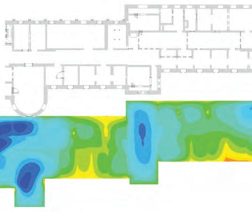
alleviate most of the reinforcing placement effort, steel fiber reinforcing in the mix was used for flexural strength and to address minimum shrinkage and temperature criteria. The steel fiber supplier, Fab-Form, provided Helix’s fibers supported by Wicke Herfst Maver’s engineered calculations to confirm dosage rates for strength and stiffness requirements in the mix design. Conventional reinforcing was used to directly engage the bearing walls and to transfer load to the post bases for gravity and uplift load resistance. While the elastic shear design values were used to qualify the middle FCCF material for horizontal shear transfer between the upper and lower concrete layer, to account for a range of anomalies including potential unforeseeable soft soil pockets, placement stoppage joints, catastrophic flood levels, or weak existing brick wall spots, steel reinforcing standees were used as a secondary, ductile and overload horizontal shear transfer mechanism.
While none of the more conventional options studied were viable, the analysis exercise illustrated that a structured fill system that used the full depth of the basement for stiffness could efficiently limit the differential settlements to the comparatively small allowable design limits for the brick masonry walls. The infill solution also armored the basement walls above grade against hydrostatic pressures and potential debris impact. Building off of the understanding that for common concrete structural elements, a lot of the actual cementitious material functions as a placeholder for reinforcing coverage or form-filler and is not used to resist stresses at a given location, the team explored concepts similar to precast concrete sandwich or wood structural insulated panels.
The final solution consisted of a structural mat foundation with 12-inch thick “flange” top and bottom reinforced conventional concrete layers with a lightweight foamed cellular fill (FCCF) shear-based mid-section. The material specifications were developed with the concrete contractor, using a full-range water reducer and a blended aggregate to enhanced flowability of the fiber-rich layers given their inherent stickiness. Establishing a 56-day test period allowed for a relatively higher water cement ratio and the use of fly ash to further allow for uniform placements from a limited amount of access locations. A range of foamed concrete strengths and densities was evaluated for required modulus and strength mechanical properties, permeability, local availability, installation, and cure time logistics, and cost performance implications. The best overall fit for the project was a 32 pounds per cubic foot (pcf) material of 250 pounds per square inch (psi) strength for the middle fill.
The existing posts and complicated cross wall geometries in the basement drove up the cost of conventional steel reinforcing placement in the mat. To
Individual building mat foundation analytical models were developed using RAM Elements. The three standard zones of subgrade modulus values were developed and incrementally iterated with the GER using results for displacement and bearing stress review and modification. The design team selected an overall design settlement limit of 1-inch and an L/600 differential settlement limit as target design parameters. While these values exceeded recommendations, the structured mat and overall renovation budget allowed for sufficient mitigation for any minor brick wall repairs that might be required. Analyses were run for each building using a range of mat materials and subgrade stiffnesses. Design properties were varied globally to account for local “soft pocket” possibilities, as well as to address creep effects. The hybrid sandwich mat foundation weighed in at an average density of approximately 60 pounds per cubic foot, with the structural capability to distribute the loads from the bearing walls and the fills to address settlement implications and resist hydrostatic uplift to the walls serving as ballast.
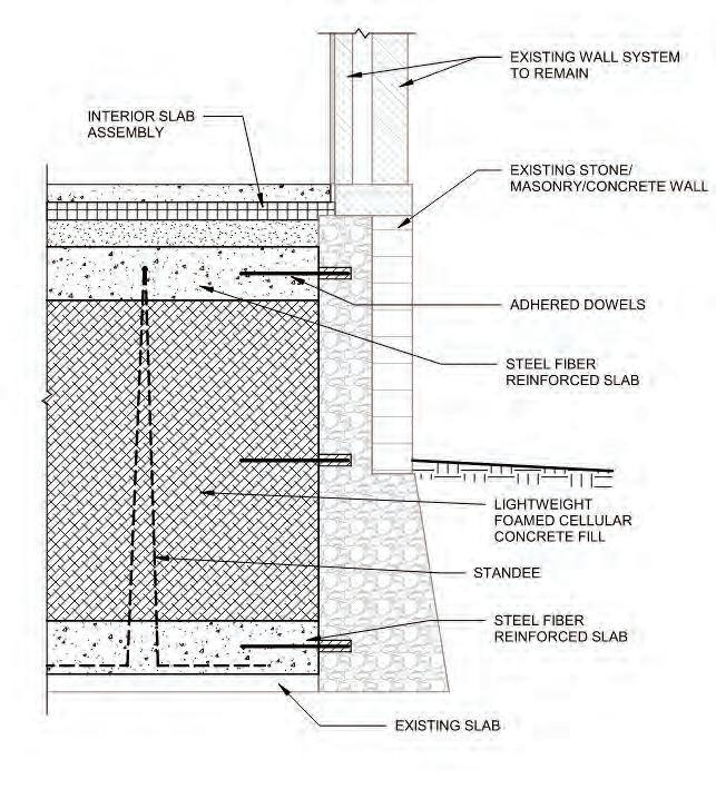
The Architectural team of Goody Clancy and Freeman, French, Freeman concurrently developed related designs and specifications for each option accounting for the moisture effects of below grade walls, building enclosures requirements, and plumbing implications. Additionally staging plans were developed with the construction team, to allow for mat installation to replace existing ground floor framing serving as wall bracing without the need to temporary shoring. As an integral part of the design and pre-construction assessment and estimating work, material testing and survey monitoring plans were developed. These included density, strength and modulus testing for the mix designs during construction for both layers. Surveys taken throughout construction before and after the mat pours found total settlements of up to
STRUCTURE magazine 48
A
Shown is the plan view of the basement bearing wall layout with moment distribution with uplift and gravity loads using RAM Elements software.
schematic section of sandwiched mat foundation is detailed.
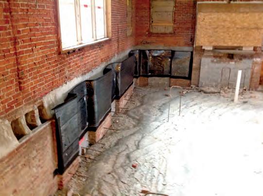
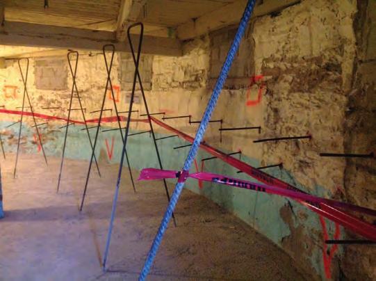
5/16-inch, averaging in the range of 3/16-inch, with associated differential settlements not exceeding established L/600 curvature levels. Settlement distress from the mat work has not been observed, and uplift-inducing recent flooding has not resulted in any reported issues.
The preservation of the historic portions of the Waterbury State Office complex for community and environmental well-being required the engagement of the Owner, Construction team and Design consultants in all project phases. Their collaboration, effort and expertise to expand conventional solution boundaries is reflected in the facility’s recent resilient performance against flood conditions similar to those
that caused previous damage. The sandwich mat foundation system was found, and now tested, to be an economical solution that met the State’s preservation goals. ■
Russ Miller-Johnson, PE, SE, is a Senior Engineer and former Principal with Engineering Ventures in Burlington, Vermont (russmj@engineeringventures.com). Miller-Johnson has served on a broad variety of projects and has designed with many types of materials throughout his sustainability-focused practice.
WOOD guide
ASDIP Structural
Software
Phone: 407-284-9202

Email: support@asdipsoft.com
Web: www.asdipsoft.com
Product: ASDIP Wood
Description: ASDIP WOOD is a structural engineering software utilized by engineers for the design of wood members, such as biaxial columns, continuous beams, and out-of-plane bearing walls. See immediate graphical results, calculations, and detailed or condensed reports with exposed formulas and code references.
SAFI Structural Engineering Software
Phone: 800-810-9454
Email: sales@safi.com
Web: www.safi.com
Product: GSE Software
Description: Optimize workflow efficiency with the GSE software's hybrid solution enabling simultaneous material design, including steel, cold-formed steel, concrete, automated slab design, timber, light-frame wood, and aluminum. Experience a technology built on a powerful user-friendly interface offering advanced structural analysis capabilities and intuitive modeling features. GSE Software: Empowering Engineers since 1986.
RISA Tech, Inc.
Phone:949-951-5815
Email: info@risa.com
Web: risa.com
Product: RISA Floor
Description: RISAFloor and RISA-3D form the premiere software package for wood design. Create 3D models of your entire structure and get complete design of wood walls, flexible wood diaphragms, dimensional lumber, glulams, parallams, LVL’s and joists. Custom databases for species, design of strap and hold-downs as well as panel nailing offer.
ENERCALC,
LLC
Phone: 800-424-2252
Email: info@enercalc.com

Web: https://enercalc.com
Product: ENERCALC SEL/ENERCALC 3D
Description: Count on ENERCALC SEL for analysis and design of wood beams, wood columns, wood shear walls, wood ledgers, and even flitch plated wood beams. Built-in databases include section and material properties from NDS, as well as properties for common engineered wood products. SEL subscriptions provide both installed and cloud use.
MAY 2024 49
The exterior wall with fill system and waterproofing measures is shown in progress at a crawl space location after lower mat layer installed. Photo by Engineering Ventures, PC.
The basement bearing wall mat mid-layer reinforcing installation and standees in lower layer is in progress here. Existing wood floor framing is left in place for bracing until mid-layer is sufficiently cured. Photo by Engineering Ventures, PC.
Monthly 2024 Resource Guide forms are available on our website. Not listed? STRUCTUREmag.org
NCSEA News
NCSEA Announces Its 2024-25 Board of Directors
The National Council of Structural Engineers Associations is pleased to announce its 2024-25 Board of Directors.
• Chris Cerino, PE, STV, Inc., will serve as its president, replacing Ryan Kersting, SE, Buehler Engineering, Inc., who will transition to Past President for one year before exiting the Board.
• Jami Lorenz, SE, SMA Architecture + Design, P.C., was named vice president, and Ken O’Dell, SE, MHP, Inc. Structural Engineers, as its secretary. Brian Petruzzi, PE, Meta, will serve his second year as Treasurer.
• Jeannette Torrents, PE, SE, JVA, Inc., will be Senior Director. The Senior Director is a new Board position that expands the Board’s capacity to manage additional initiatives by extending the service of an experienced Director.
• Michelle Ryland, SE, RA, Klein & Hoffman, Inc., and Andrew Lovenstein, PE, SI, J.S. Held, LLC, have been newly appointed as directors.
Board of Directors member terms began April 1, 2024, and will conclude on March 31, 2025. To learn more about the NCSEA Board, please visit: https://www.ncsea.com/about-ncsea/ncsea-board/.


STRUCTURE magazine 50
May 14 Cantilever Column Systems May 21 Champlain Towers South—WJE Collapse Investigation June 4 The Parametric Genome—A Structural Approach June 13 Other Structures: KF Aerospace Spiral Stair NCSEA
NCSEA webinar
access to all the educational
ever need! Subscribers receive access to a full year’s worth of live NCSEA education webinars (25+) and a recorded library of past webinars (170+) – all developed by leading experts; available whenever, wherever you need them! Recommendations for Performing Structural Engineering Quality Assurance Reviews Visit www.ncsea.com/education for
latest news on upcoming webinars and other virtual events.
Webinars Purchase an
subscription and get
content you’ll
the
President
Chris Cerino, PE STV, Inc.
Past President Ryan Kersting, SE Buehler Engineering, Inc.
Secretary Ken O’Dell, SE MHP, Inc. Structural Engineers
Treasurer Brian Petruzzi, PE Meta
Senior Director Jeannette Torrents, PE, SE JVA, Inc.
Director
Cervente D. Sudduth, PE ENV SP Dubois Consultants
SMA Architecture + Design
Director
Angela Stasulis, PE, SE Shear Structural
Michelle Ryland, SE, RA Klein & Hoffman, Inc.
Director
Andrew Lovenstein, PE, SI J.S. Held, LLC
News from the National Council of Structural Engineers
NCSEA Foundation Announces Its 2024-25 Board of Directors
The NCSEA Foundation is pleased to announce its 2024-25 Board of Directors.
• Tricia Ruby, Ruby + Associates, a Degenkolb Company, will serve as its President, replacing Emily Guglielmo, Martin/Martin Consulting Engineers, who will transition to Past President.
• Tom Grogan was named Vice President.
• Ron Klemencic, Magnusson Klemencic Associates, and Lauren Piepho, HGA, have been newly appointed as Directors. Board of Directors member terms began April 1, 2024, and will conclude on March 31, 2025. To learn more about the NCSEA Foundation, please visit www.ncsea.com/foundation/about/.


Call for NCSEA Awards Nominations
The NCSEA Special Awards are presented to members who have provided outstanding service and commitment to the association and to the structural engineering profession. The categories for these awards include the NCSEA Service Award, the Robert Cornforth Award, the Susan M. Frey NCSEA Educator Award, and the Susan A. Jorgensen Presidential Leadership Award.
NCSEA’s Structural Engineering Excellence (SEE) Awards highlight structural engineering ingenuity throughout the world and incredible achievements in the profession. Projects are judged on innovative design, engineering achievement and creativity. NCSEA encourages both structural engineers and structural engineering firms to submit their projects, providing an opportunity to showcase their successes and accomplishments.
The awards are presented in the following categories:
• New Buildings < $30 Million
• New Buildings $30 Million to $80 Million
• New Buildings $80 Million to $200 Million
• New Buildings Over $200 Million
• New Bridges or Transportation Structures
• Forensic/Renovation/Retrofit/Rehabilitation Structures < $20 Million
• Forensic/Renovation/Retrofit/Rehabilitation Structures > $20 Million
• Other Structures
For more information on how to submit, visit www.ncsea.com/events/awards/. Entries are due Monday, June 17.
The winners will be honored at NCSEA’s Structural Engineering Summit, Nov. 5-8, in Las Vegas, in STRUCTURE magazine, in a professionally produced video, and on the NCSEA website.
Associations 51 MAY 2024
President Tricia Ruby Ruby + Associates, a Degenkolb Company
Past President Emily Guglielmo, PE, SE Martin/Martin Consulting Engineers
Vice President Tom Grogan, PE, SE
Director
Ron Klemencic, PE, SE Magnusson Klemencic Associates
Director Lauren Piepho, PE HGA
Director Judy Lio, Professor School of Civil & Construction Engineering, Oregon State University
Jami Lorenz, PE SMA Architecture + Design
Director Brian Petruzzi, PE Meta
Director Sara Roberts, PE KPFF

SEI Update
Highlights From SEICon24
This past March, this year’s SEI annual conference SEICon24 held in collaboration with NASCC Steel Conference, showcased a fusion of innovation, expertise, and collaboration within the structural engineering community. From the heart of San Antonio, attendees were warmly greeted, setting the stage for a wide exchange of ideas and learning.
SEICon24 marked a significant milestone as SEI celebrated more than 90 Futures Fund scholarship winners. The participation of these budding young professionals and students injected palpable energy into education sessions and events like our Meet the Leaders breakfast. Education sessions offered attendees a wealth of knowledge and expertise, covering a spectrum of topics ranging from cutting-edge design standards to emerging trends in the field. Notable addresses from SEI President Jerry Hajjar and SEI Fellow David Odeh underscored the importance of sustainability, resilience, and innovation in structural design, reaffirming the community’s commitment to advancing the field. Attendees were challenged to adapt their designs to meet the evolving demands of emerging global challenges. Celebrations were in order as SEI President Jerry Hajjar was honored with the prestigious SSRC Lynn S. Beedle Award for lifetime achievement. This esteemed recognition serves as a testament to Hajjar’s unwavering dedication to the field.
Against this backdrop of celebration and recognition including ASCE/SEI award winners and new SEI Fellows, SEICon24 emerged as a rounding success, having fostered collaboration and strengthened the community’s commitment to advancing the art and science of structural engineering. As we shift our focus to the future, excitement mounts for Structures Congress 2025 in Phoenix, which promises to continue the tradition of ingenuity, education, and advancement.


STRUCTURE magazine 52
ASCE/SEI Awardee Recognition
News of the Structural Engineering Institute of ASCE

SEI Futures Fund
Give your gift of support to champion the future of structural engineering. Join us to invest in the next generation of young professionals, supporting innovation, and advancing our field towards new heights. Learn more at www.asce.org/SEIFuturesFund.
“Thank you to the SEI Futures Fund for their support to attend SEICon2024! It was very informative and inspiring, expanding my horizon to the new and emerging trends developed by different professors and industry leaders. Meeting like-minded engineers, networking during the event, receiving feedback and comments from the experts on my research topics, and learning techniques from successful leaders to sharpen soft skills were highlights for me.”
—Sheila Ariana, S.M.ASCE
Remembering Jim Rossberg, Founding SEI Director
We are very sad to share the news that our friend and colleague Jim Rossberg passed away on March 25. Rossberg launched the Structural Engineering Institute in 1997, one of ASCE’s first two Institutes. His list of accomplishments is extensive, and his legacy lives on at SEI/ASCE.
Read more at https://www.asce.org/publications-and-news/civil-engineering-source/article/2024/04/04/ jim-rossberg-who-launched-asce-7-the-structural-engineering-institute-and-the-societys-9-11-investigations-dies-at-65.
Congratulations to O.H. Ammann Research Fellowship Recipients
• Sheila Ariana, S.M.ASCE, University of Massachusetts, Amherst
• Pedram Bazrafshan, S.M.ASCE, Drexel University
• Abdullah Braik, S.M.ASCE, Texas A&M University
• Henrique Martins, S.M.ASCE, University of Notre Dame
• Xukai Zhang, S.M.ASCE, Texas A&M University
Learn more at O. H. Ammann Research Fellowship in Structural Engineering | ASCE
53 MAY 2024
SEI Futures Fund Scholarship Recipients
CASE in Point
Tools To Help Your Business Grow...
CASE has committees that work together to produce specific resources available to members, from contract documents to whitepapers, to help your business succeed.
If you are a member of CASE, all CASE publications are free to you. NCSEA and SEI members receive a discount on publications. Use discount code - NCSEASEI2022 when you check out.
Check out some of the new CASE Publications …
CASE Commentary D: Teaming Agreements
An important aspect of a joint project pursuit between a contractor or design professional and a structural engineer is an agreement covering the activities of the parties prior to contract award. This agreement is commonly referred to as a teaming agreement. Teaming agreements are often associated with design-build projects but can be used on any project pursued jointly by two or more parties. Many organizations familiar to structural engineers provide a standard form teaming agreement. This commentary summarizes the contents and typical clauses of the standard form teaming agreements offered by four of these organizations:
• American Institute of Architects (AIA): Contract C102-2015
• Engineers Joint Contract Documents Committee (EJCDC): Contracts D-580 and E-580
• Design-Build Institute of America (DBIA): Contract No. 580
• Consensus Docs: Contract Nos. 296 and 498.
Guideline 976-D: Commentary on 2020 Code of Standard Practice (COSP) for Steel Joists and Joist Girders

The Steel Joist Institute (SJI) Code of Standard Practice (Code or COSP) for steel joists and Joist Girders establishes trade practices for the steel joist and Joist Girder industry. The practices presented in the COSP are “in accordance with good engineering practice, tend to ensure safety in steel joist and Joist Girder construction, and are standard within the industry” (Section 1.1). Unlike the AISC Code of Standard Practice, the SJI COSP is not a comprehensive summary of acceptable practices for all involved parties, including the fabricators, erectors, structural engineers, owners and general contractors or construction managers. Rather the SJI COSP is focused primarily on the characteristics and properties of joists and Joist Girders themselves and the structural engineer’s responsibilities in properly specifying them for the purposes of design, bidding and installation.
The specification of joists and Joist Girders can provide an economical structural solution, but there are very specific requirements that must be understood by all parties. The 2020 SJI COSP provides a practical approach to specifying joists, to introduce design terms for use by the structural engineer, and to identify and clarify topics that may have been subject to varying interpretation in the past. This commentary provides observations and analysis of specific aspects of the COSP that have a direct impact on the structural engineer’s practice of specifying steel joists. A familiarity and understanding of the entire SJI COSP is necessary to ensure the proper design and documentation of steel joists and Joist Girders. However, the following discussion highlights sections of particular interest to the specifying structural engineer.
You can purchase these and other Risk Management Tools at https://www.acec.org/member-center/get-involved/coalitions/case/resources/
Is there something missing for your business practice? CASE is committed to publishing the right tools for you. Have an idea? We’d love to hear from you!

Follow ACEC Coalitions on LinkedIn: www.linkedin.com/in/acec-coalitions
STRUCTURE magazine 54
News of the Coalition of American Structural Engineers
Upcoming Events
Joint Town Hall Event with CASE, NCSEA, and SEI
Recording Available
Leadership from CASE, NCSEA, and SEI hosted a virtual joint town hall event to discuss how the three organizations are progressing to fulfill the Vision for the Future of Structural Engineering (adopted April 2019), highlighting initiatives to advance the profession and enhance member engagement.

The town hall is an opportunity to catch up on things you might have missed and gain insight into what the three organizations are doing moving forward.
This complimentary event was recorded and is available to watch. Check out: https://program.acec.org/joint-town-hall-event-case-ncsea-and-sei
Managing Small Projects Successfully
May 29-June 6, Online
For engineering firm project managers and firm principals, smaller projects can be a core revenue driver. But, smaller projects can potentially carry big risks that can be a drag on resources, profitability, and client satisfaction. The good news is this course puts the right set of skills in your toolbox to ensure that small projects deliver maximum profits.
Register now for Managing Small Projects Successfully: How to Prevent Small Projects from Becoming Big Problems and learn the skills, hacks, secrets, formulas, trouble-shooters and problem-solving that make engineering firm executives and clients delighted with small project progress and outcomes.
From planning, scheduling and budgeting to team management and business development, this live online program packs everything you need into just 8 hours of instruction, broken into two-hour sessions to work with your busy schedule. It is packed with proven insights from the engineering project management experts at PSMJ Resources, Inc.
Earn up to 8 PDHs!
www.acec.org/event/managing-small-projects-successfully-howto-prevent-small-projects-from-becoming-big-problems-summer-2024/
CASE Summer Meeting
August 8-9, Minneapolis, Minnesota

Save the date! The CASE Summer Meeting will be in Minneapolis, Minnesota this year. The meeting will feature breakout sessions for the CASE Committees, interactive discussions on structural engineering and business resources, education sessions, and more. Registration coming soon. Follow the coalitions LinkedIn page to stay up to date. https://www.linkedin.com/in/acec-coalitions.
55
MAY 2024
Make lasting
Steel roof and floor deck with realistic wood-grain finish
Get wood’s natural beauty and steel’s unmatched strength — all in one innovative structural building component. Introducing IMPRESSIONS™, a revolutionary steel roof and floor deck available in six distinct digitally printed wood-grain finishes so realistic, you won’t believe it’s steel. Realize your architectural visions while achieving project goals. Together, let’s build it better.

newmill.com/impressions
LEARN MORE
structural

It Is OK to Struggle
The structural engineering profession has many stressors, and asking for help is one of the strongest ways to cope.
By Chad S. Mitchell, PE, SE
The structural engineering profession is full of stressors. Whether life safety, deadlines or cost/budget concerns, there is never an absence of stress. Even the best engineers have their challenges; they either have tools to manage the stress or they likely hide their struggles. Per a 2016 Center for Disease Control and Prevention study, architects and engineers had the fifth highest suicide rate at 32 per 100,000, double the national rate at the time. As May is National Mental Health Awareness Month, this article aims to provide insight and resources for taking care of your mental health and supporting colleagues who may be struggling. I personally have struggled as the years since COVID-19 turned our world upside down. However, the pandemic was not the only cause of my struggles. I always had a lot on my plate, as people would say, but I seemed to be able to manage the stressors. As my responsibilities grew, my toolset to manage the stress grew at a much slower rate. Because I am one of those who hide their struggles, it may not have been noticed, but it surely was happening.
The struggles have pushed me to the point of looking for change. I love what we do. I consider engineering one of my love languages and cannot imagine doing anything else. But I am unable to continue in the industry in the long-term without changes.
Stressors
Structural engineering contains so many variables that we need to work through, and the stakes are high. Too often, we are asked to push the
limits of physics to make our clients’ visions a reality. As technology advances with BIM software, we are often asked to work through designs that are constantly changing.
With the increase in material costs since the pandemic, we often are asked to redesign multiple times, with multiple materials to get the budget to pencil. The design team is often under unrealistic deadlines due to jurisdiction review backlogs.
Firms that are understaffed require their engineers to take on more projects. These engineers meet company goals by working longer hours or rushing through processes—or both. With a looming enrollment cliff at engineering schools created by lower birth rates, reinforcements do not appear to be coming.
Adding the stresses from personal life, these all combine for an environment I have not seen in my two-decade career.
Solutions for Industry
We as structural engineers cannot control most of the causes of our stress. We cannot control the nature of our industry: the deadlines, the costs, the clients. We can, however, work on the tools we use to manage the external pressures.
As firm leaders, we need to set our teams up for success. We need to do a better job planning and properly staffing our projects, improving the training of new engineers so that the struggle is not technical shortcomings, and pushing back on clients when deadlines
MAY 2024 57
are unreasonable and designs are unrealistic. It is important to have a plan in place for employees having mental health issues. The plan can include something as simple as checking in on employees who seem to be struggling at work. It is not a technical issue that they are struggling with, but the stresses of their career. Simply checking in on an employee might be enough to open up the discussion of mental health. Being isolated and feeling alone in work can add to struggles. I speak from experience. It is important to be there for our work families. We may not always have the solution, but being able to be open with struggles is such a powerful step. In times of mental health crisis, firms should have a plan on how to react—similar to plans for other emergencies.
Solutions for Me
My biggest step to working through my struggles was to be open and not hide them. I do not have the toolset at this time to manage everything alone. Being honest with my supervisors that I was struggling gave me an opening to start working on my mental health. A part of this is normalizing mental health struggles. I have recently started seeing a therapist and it has been a game changer. As engineers we think we can solve any problem. But there are just too many unknowns in the equation that is the human mind. In my last session, my therapist introduced me to a concept called “Ask vs. Guess” culture. In Ask culture, people ask for help when they need it. Guess culture people worry that they will inconvenience people by asking for help. A trap I fell into as my struggles started was to hide them and try to dig out of the hole by myself. I thought that if I just worked a little more, I could get ahead. I was trying to do everything myself, thinking my coworkers were too busy to have time to help me with my struggles. Being able to ask for help and delegate work is essential. I am just now understanding this, and it has changed things greatly.
“No” is a complete sentence. I have always had a hard time saying no to things. I am a member of too many professional society committees. Assess your commitments and focus on those that you are truly passionate about, while passing on the opportunities that do not align as well with your interests and schedule.
It is important to stay physically healthy as well. Take walks. Take actual lunch breaks. Do not eat lunch at your desk while working on a Revit model. Take the time to recharge. These steps, pun intended, can help with mental health. Studies have shown a link between physical and mental health. Exercise increases levels of dopamine, which has been shown to reduce depression and anxiety.
Increasing our R-Factor
As structural engineers design a building for seismic, we have two approaches that can be used. One is to provide an over-strength factor, which increases the forces for which lateral resisting elements need to be designed. Members are designed such their capacity is much greater than the forces created by the maximum earthquake event. This is analogous to the just work harder mentality.
This works well for low seismic regions. But when in higher seismic areas, the overstrength approach creates loads that are much higher than what would be reasonable for the design of members. To account for this, ductility is introduced into the lateral system to dissipate energy from the earthquake. This ductility
Helpful Resources
Suicide & Crisis Lifeline Call or Text 988
National Suicide Prevention Lifeline 1-800-273-TALK www.psychologytoday.com
allows the seismic loading to be reduced by increasing the response modification factor (R-Factor). A system design with ductility considered, such as a special moment frame (R=8), has a third as much force as a moment frame that does not consider ductility requirements (R=3).
We need to increase our R-Factors to combat the stressors we have in our profession. Build in ductility. Therapy is my ductility. Talking about my struggles is my ductility. Writing this article is my ductility.
Ask
If you are struggling like me, do not hide it. The old way was just to work harder; be stronger; don’t complain. This only attracts more load. Let people know you are struggling. They can help. Reaching out for help is not a weakness. It is one of the strongest things you can do.
Therapy is covered by many insurance plans. If it is not, I would challenge firm leaders to find a way to encourage that mental health be covered in some way. Firms pay for continuing education, why not an allowance for therapy? In the United States, most health insurance is company-provided. Companies realized that healthy employees are productive employees. Mentally healthy employees are even more productive. Invest in the mental health of your employees. In the hiring struggles, it is financially prudent to do what you can to keep employees vs. finding new ones when they leave due to burn out.
If you would like to start therapy, you can search for a therapist in your area at www.psychologytoday.com.
Normalizing mental health will make it easier for people to ask for help. Build local networks of friends, family, and coworkers who understand what stresses you deal with day today and that you can count on in times of need.
Find ways to personally recharge. Practice meditation or try breathing exercises. When I am in a stressful situation, I tend to forget to breathe. The simple step of focusing on breathing is a way for me to bring down my anxiety. Mindfulness apps on your phone also can help with anxiety. Firms should be open to offering ways to allow employees to recharge or step away temporarily if needed. A refreshed employee is much more efficient than a burned out one—and much more efficient than training a replacement. Help is out there! And be the help others need! ■
Chad S. Mitchell, PE, SE, is an Associate Principal at S. A. Miro, Inc. in Denver, Colorado and past president of the Structural Engineers Association of Colorado (SEAC). He is currently SEAC’s delegate to the National Council of Structural Engineers Associations (NCSEA). Structural engineering is his love language, and he is loving therapy as his way to work at tackling this crazy equation called life. (cmitchell@samiro.com)
STRUCTURE magazine 58