SUSPENSION SOLUTION DATASHEET
STRUT-LOCK SYSTEM (M10) The M10 STRUT-LOCK system is used to support HVAC and M&E services from the Y-RANGE of Zip-Clip wire supports. The devices are typically installed into profile channel which can then be hung from a wire suspension.
FEATURES • 18th Edition Amendment 2 : 2022 compliant. • Versatile – Use with channel nuts or nuts and washers (metric only). • Quick to install and adjust. • Safe Working Load (SWL) of 90 kg each per suspension. • Secure lock-off. • Manufactured from mild steel. • Bright zinc plate finish.
APPLICATIONS • Single-tier trapeze brackets. • Multi-tier trapeze brackets. • Attach to existing bracketry. • Compatible with 41×41 and 41×21 profile channels plus other channel types when compatible channel nuts are used (metric only).
FIXING OPTIONS The M10 Strut-Lock system is available with the following fixing terminations: LOOP END: To form a choke knot for wrap-around anchor points such as purlins or I-beams. Ensure anchor points are suitable. Product code suffix: TPDM1020LPY. M6 CONCRETE HAMMER FIXING: BS8539 approved with ETA, offering shallow embedment into cracked and non-cracked concrete. Ensure base material is suitable. Contact Zip-Clip for installation details. Product code suffix: TPDM1020CY. FO-11-05
Iss.001
Jan. 2021
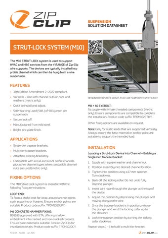
DESIGNED FOR STATIC LOADS THAT ARE SUPPORTED VERTICALLY
M8 × 60 EYEBOLT: To couple with female threaded components (metric only). Ensure components are compatible to complete the Installation. Product code suffix: TPDM1020THY. Other fixing options are available on request. Note: Only for static loads that are supported vertically. Always ensure the base material or anchor point are suitable to support the intended load.
INSTALLATION Locating a Strut-Lock Device Into Channel – Building a Single-tier Trapeze Bracket: 1. Couple with square washer and channel nut. 2. Position assembly into desired channel location. 3. Tighten into position using a 17 mm spanner. Turn clockwise. 4. Back-off the locking collar. Do not undo fully. Depress plunger. 5. Insert wire rope through the plunger at the top of the device. 6. Adjust the position by depressing the plunger and moving along on the wire. 7. Once the trapeze bracket is in position, release the plunger and wind the locking collar up to the shoulder. 8. Lock the trapeze position by turning the locking collar clockwise. Repeat steps 1 - 8 to build a multi-tier bracket. ZIP-CLIP.COM