A NEW STATEMENT TOWARDS A CYCLABLE BUDAPEST

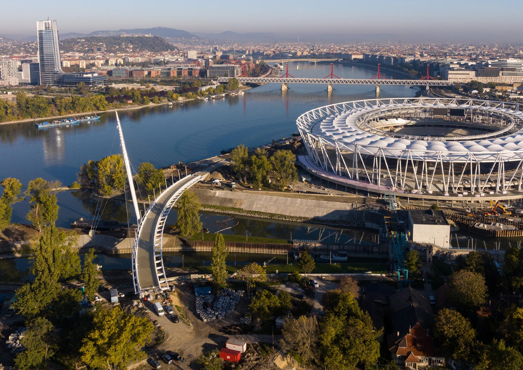
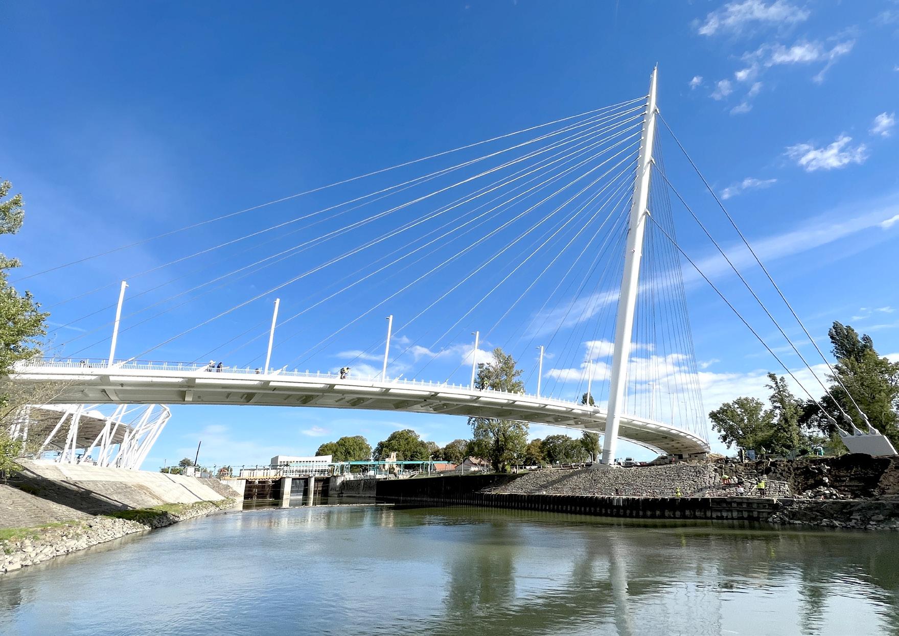
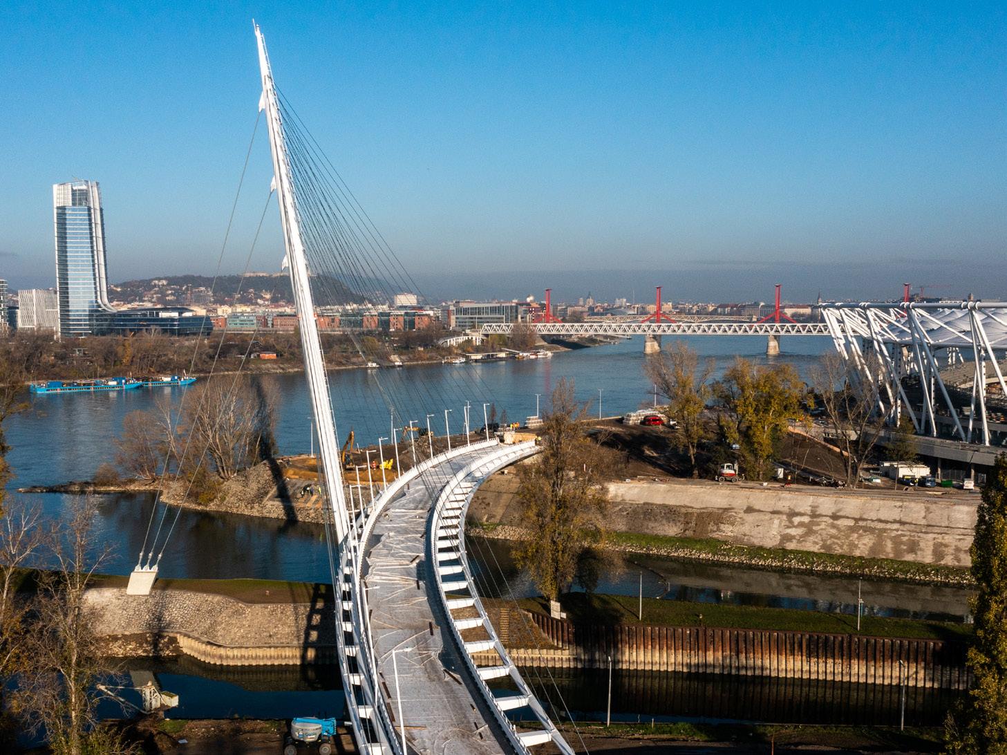
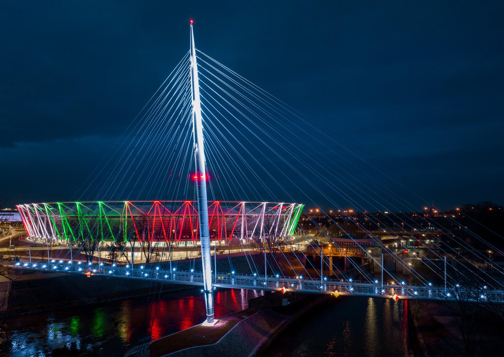
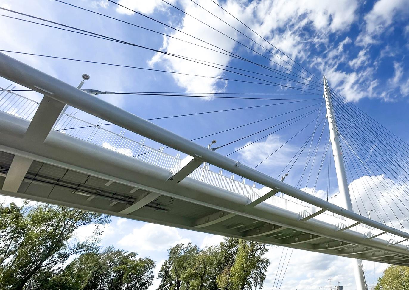
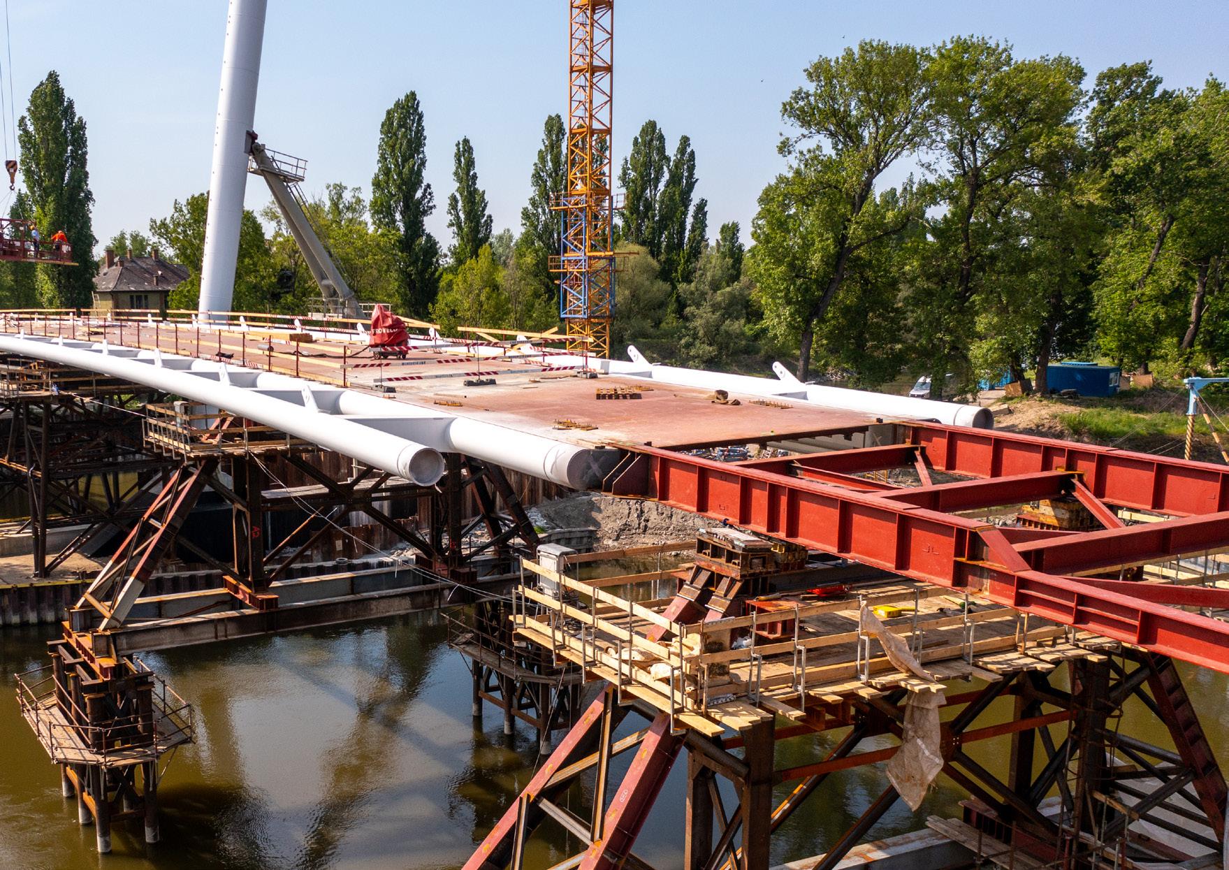
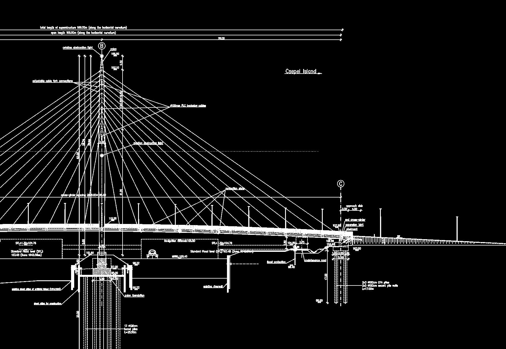
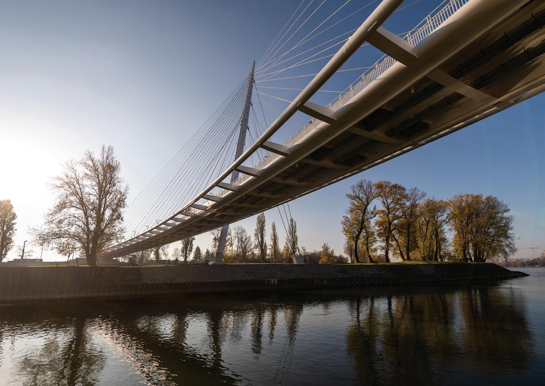
The 168 m span bridge follows a curved path along the Danube with its pylon standing on a small island. The slender cable-stayed design harmonizes with its architectural and environmental context. The 170 m long and almost 70 m tall bridge structure is the largest bridge in Budapest and Hungary, designed exclusively for pedestrians and cyclists.
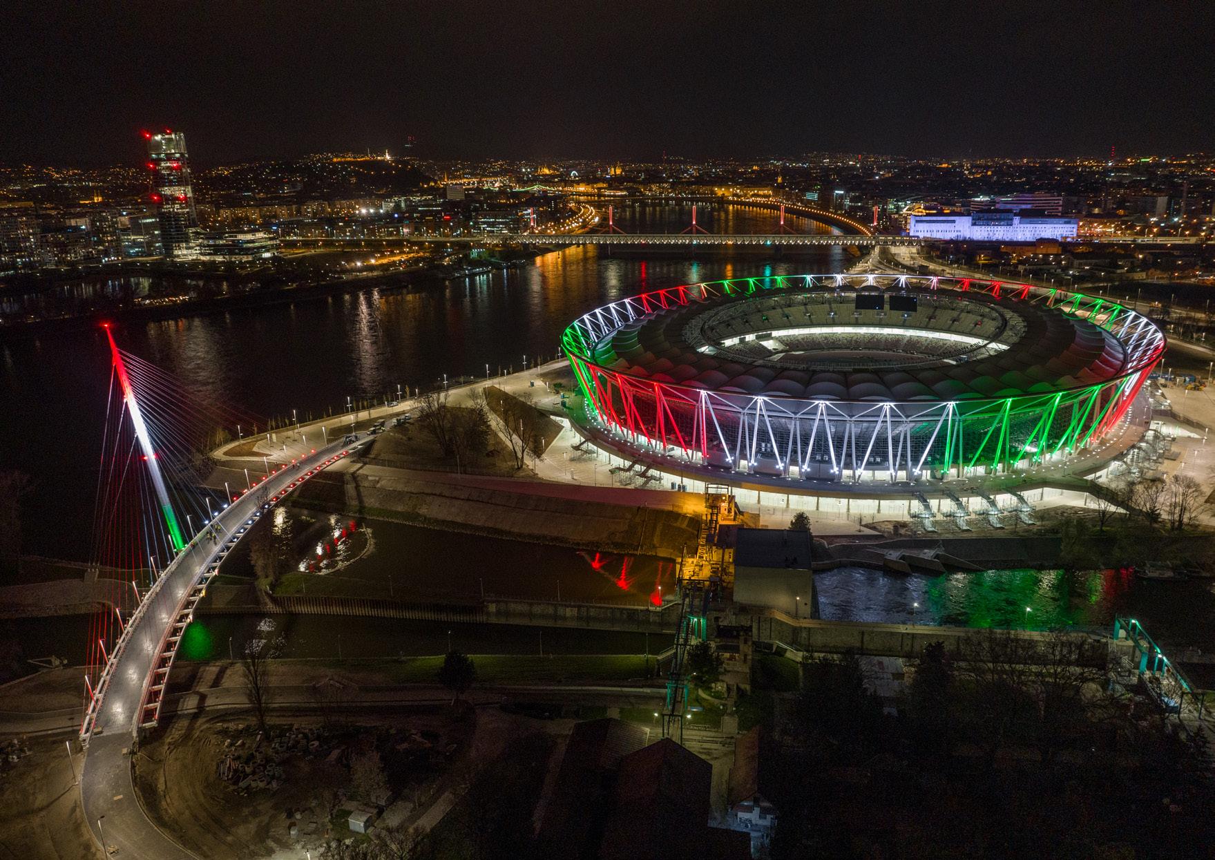
The Athletic Stadium project developed a new public space for sports and recreation by revitalizing an exceptional brownfield area of central Budapest. The pedestrian and cycle bridge plays a vital role in creating access to the Danube waterfront between the city centre and Csepel Island.
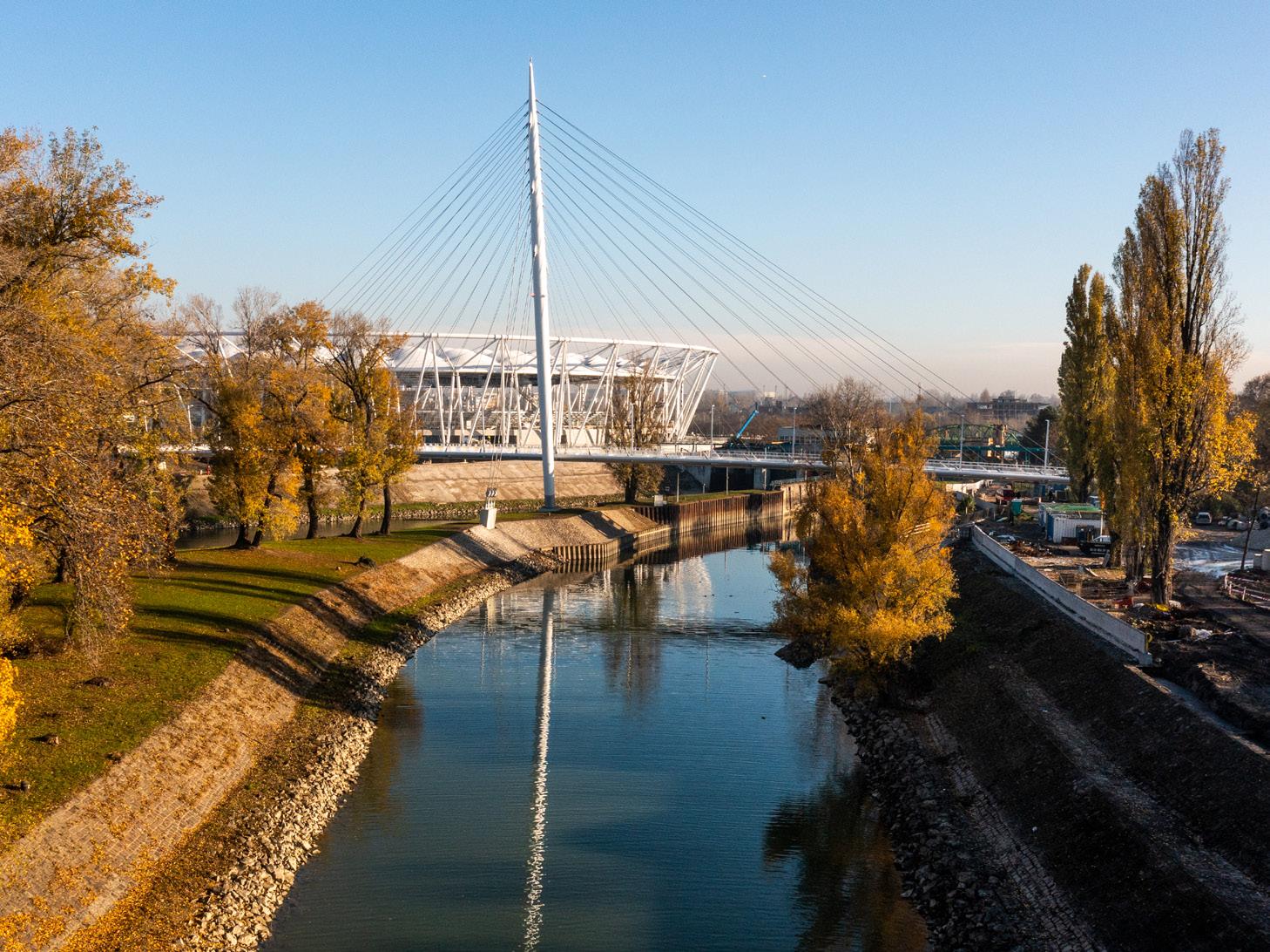
The bridge structure’s pylon is tall, yet slim and needle-like, cleverly avoiding any sense of rivalry with the stadium’s curved mass. The cable network is branching and transparent, revealing a new and exciting aspect from every angle, its rays leading skyward.
 The ‘Robinson’ Bridge is a newly built pedestrian bridge erected next to the new National Athletics Stadium in Budapest, Hungary.
pedestrian path follows the Danube
Váci Street, Central Budapest Robinson bridge
Csepel
Danube
The ‘Robinson’ Bridge is a newly built pedestrian bridge erected next to the new National Athletics Stadium in Budapest, Hungary.
pedestrian path follows the Danube
Váci Street, Central Budapest Robinson bridge
Csepel
Danube
5
Budapest, Hungary
6
TRANSPARENT STRUCTURE
The bridge structure is a single span one-pylon cablestayed pedestrian and cycle bridge with a steel-concrete hybrid stiffening girder and an orthotropic steel deck. The deck is suspended from the pylon by a two-plane cable fan system.
The pylon’s height is 65 m. Its body has a circular crosssection with a maximum diameter of 2.00 m, which tapers conically upwards and downwards. Its axis is inclined an angle of 9°.
Span:
Bridge length: Width of pedestrian path:
Total width: Height of the pylon
Steel structure
FLC cables
168,00 m without intermediate support 168,90 m
7,00 m
12,71 m 65,00 m
1020 t S460 ML and S355 M 3500 m
7
WEIGHTLESS ELEGANCE
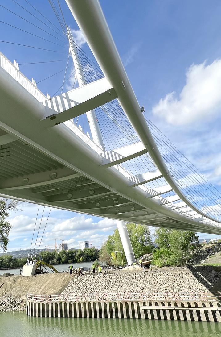
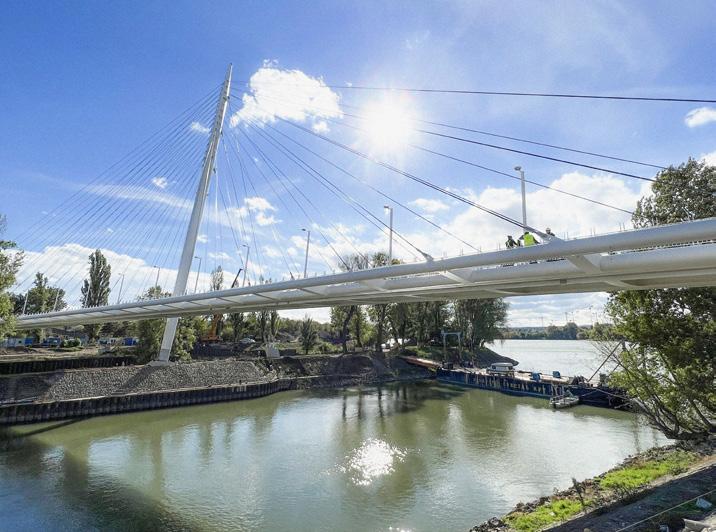
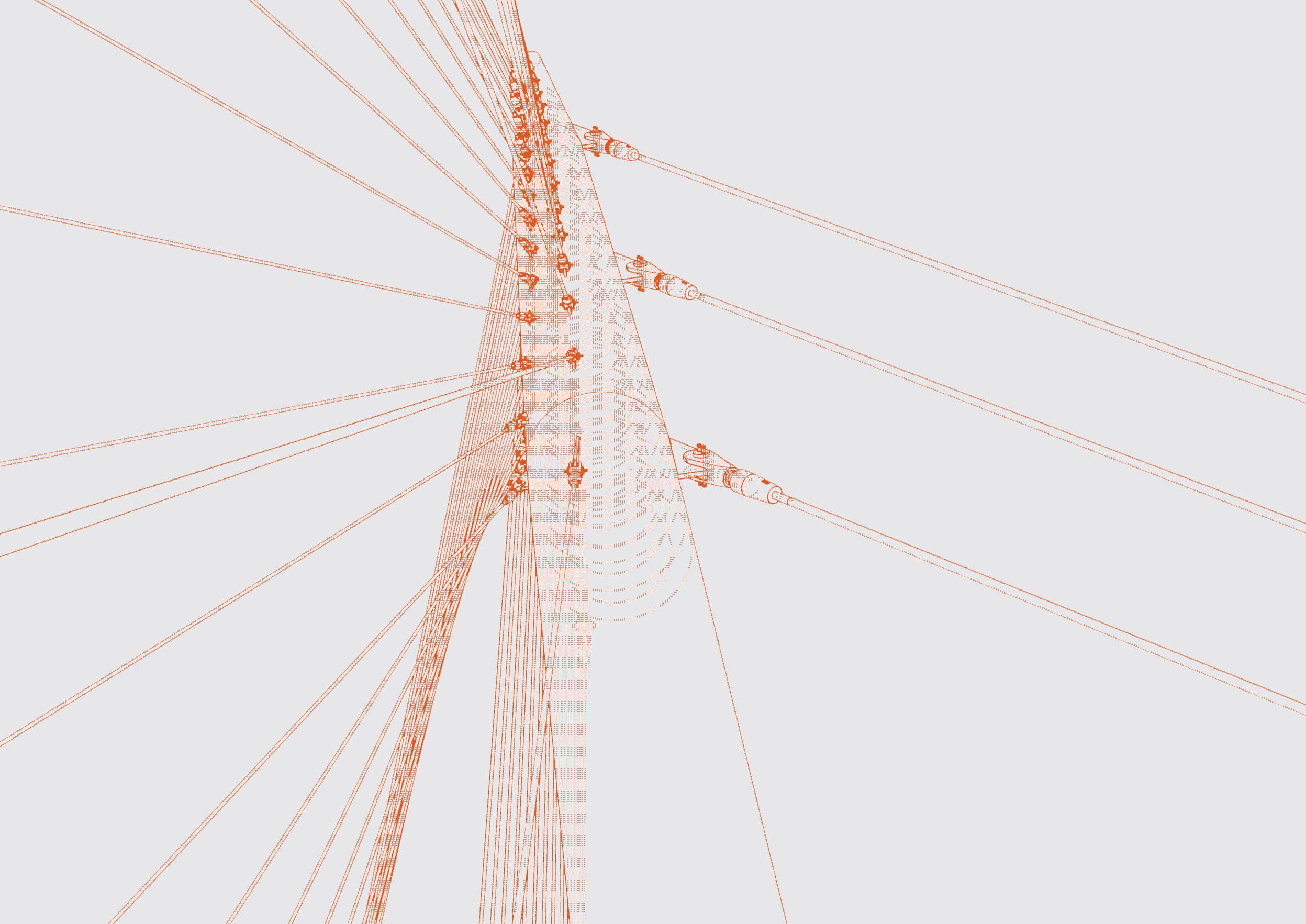
The bridge is hung on a slender steel pylon located on an artificial island that divides the Danube-branch. The pylon’s height is 65.00 m measured from the upper plane of the pile cap beam and its height above the roadway is 56.34 m. The pylon body has a circular cross-section with a maximum diameter of 2.00 m. Its axis is inclined from the vertical to the outside of the bridge at an angle of 9.0 degrees. The cable network nodes on the stiffening girder are distributed at 6.0 m intervals aligned with the crossbeams, and with a spacing of 1.5 m on the pylon. The cables are arranged symmetrically in a fan shape in the longitudinal direction. The bridge deck is supported by 53 small-diameter FLC suspension cables. The back anchorage stabilizing the pylon is located 25 m away, with three 100 mm-diameter cables used for anchoring.
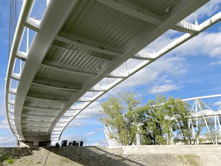
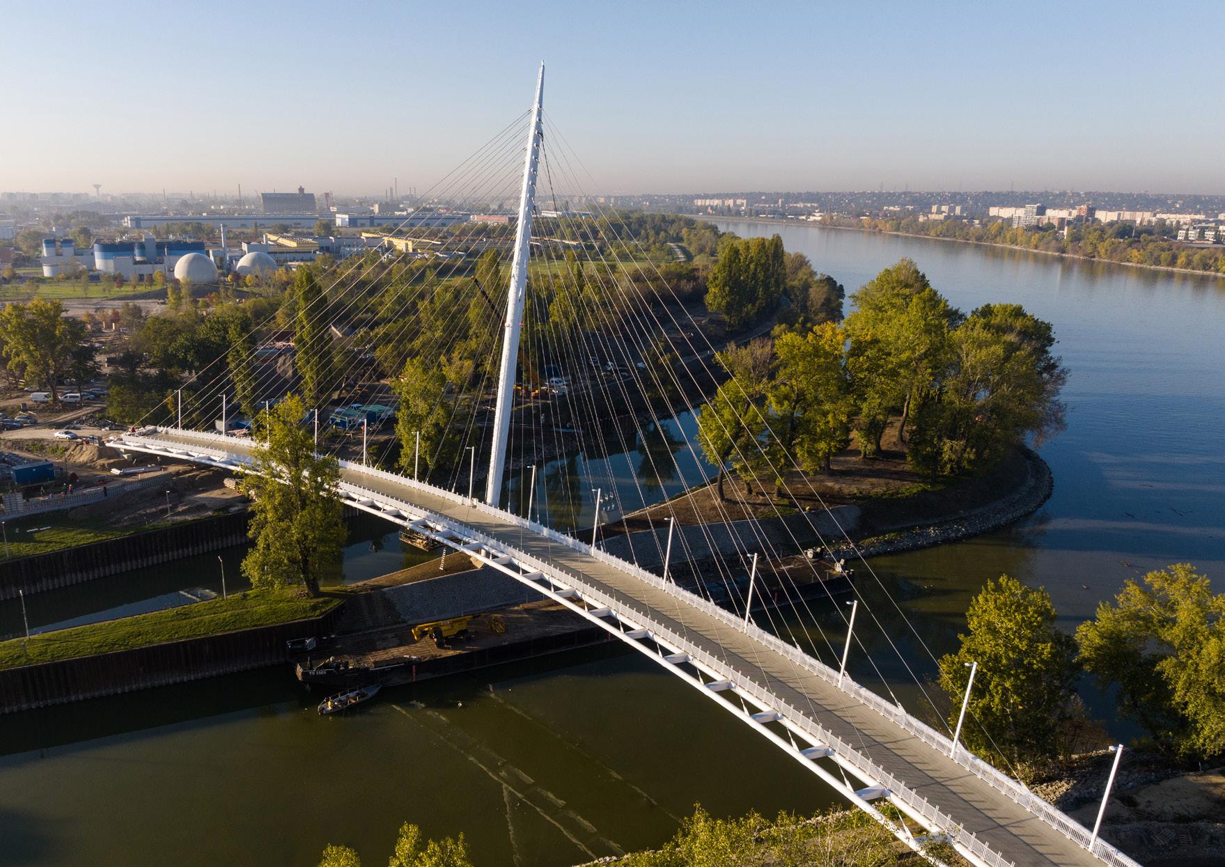
The layout of the superstructure is arranged in a pure circular curve with a radius of 275 m. Total width of the deck is 12.71 m, and the free width of the walkway between the railings is 7.00 m. The bridge deck girder consists of two welded box-sections, and an orthotropic steel deck plate in between. The structural height of the superstructure is only 900 mm. To ensure adequate pedestrian clearance on the bridge’s curved plan, the cables were cantilevered outside the main girders. Steel edge beam tubes were used with a diameter of Ø610 mm on either side, connected to the deck as a continuation of the cantilevered crossbeams. Both the edge beams and the box sections of the deck were filled with concrete.
8
The use of the edge beams as tubes not only made the roadway transparent, but also enhanced the spatial experience and ensured a seamless connection between the bridge structure and the adjacent Stadium building’s key architectural details.

The cross-section of the tubes is asymmetric, with the axis of the edge beam being situated 3.00 m away from the axis of the main girder on the inner side of the curve, and 1.50 m away on the outer side. Both the edge beams and the box sections of the deck were filled with concrete.
The superstructure was constructed with a vertical alignment of R=1600 m. The roadway’s highest point is 2.2 m above the bridge abutments.
Bearing arrangement
9
General cross-section

10

11

12

13
TOP VIEW OF PYLON FOUNDATION
14
Side view of pylon foundation
SUBSTRUCTURES
The abutments are solid monolithic reinforced concrete structures with pile foundations and parallel wing walls. Piles and pile walls were used to withstand the significant horizontal loads acting on the substructure, providing excellent horizontal support.
A unique bearing arrangement is designed to transfer the reaction forces between the abutment and the superstructure: a total of 3 bearings support the superstructure at each abutment. Due to the horizontal curvature of the deck and the inclined cables, significant lateral force is required to maintain the superstructure in position (~4000kN). As considerable tensile force is also required, the two effects were separated in the design: the outer bearing provide vertical (uplift) support, while a purely compressed bearing was used to transfer the horizontal lateral force resulting from the curvature. These bearings were placed on small shear cantilevers, formed on the bottom side of the end-crossbeams. The bridge is balanced in its own weight; longitudinal forces can only arise from seismic and live loads.
The intermediate support constructed on the artificial island is a hidden monolithic reinforced concrete pile cap with bored piles. It provides a rigid moment-resisting connection for the steel pylon and it also anchors the backstay cables that stabilize the pylon. Its geometry was designed to meet these functions. To absorb the significant tensile forces of the 3 large-diameter cables that provide the pylon’s backstay, a steel element was cast into the pile cap.

THE ROBINSON BRIDGE
HÍD DÉLI ÖSSZEKÖTŐ VASÚTI HÍD LACZKOVICH JÓ Á UTCA ÍDÉ RO LACZKOVICH CSEPELRAKPART HELYIKIKÖTŐÚT TH 38086/13 (38039) 86/5 (3808 12 (3 (38021/3) 38086/78 38038/8 3801 34) (38038/15) 38017/35 (380 /67) (38086/65) (38086/65) (38086/6) 23815/2 08 (38045/4) (38086/152) (3 (38086/155) (38086/160) (38086/161) (38 808 5) (38086/234 (3808 235 4) (38088/3) 86 1) (38086/149) (38086/148) (38045/3) 38086/255 (38086/254) (38086/233) (38086/240) 38086/23 38086/2 CS PE RA HAJÓÁ szennyvíz N HÍD ÖSSZEKÖTŐ VASÚTI HÍD LACZKOVICH KÖNYVES KÁLMÁN KÖRÚT JENŐ KÖ HAJÓÁLLO SUTCA Ő UT ROKSÁ ÚT LACZKOVICH UTCA CSEPELRAKPART HELYIKIKÖTŐÚT É (38039) 3808 (3886 16/1) 38017/33 38089 38086/78 (38017/37) 38038/8 (38038/9) (380 (38038/15) 38086/80 (38086/70) (38086/67) (38 (38086/65) 38086/33 23815/2 38086/9 38086/9 (3 (38045/4) 08 0) (38086/152) (380 15 (38086/155) (38086/160) (38086/18 (38 6/ 8) 6/2 (3808 /238 (38 37 38088/ (38088/3) 15 (38086/149) (3808 (38045/3) 38038/14 09 38090/2 (38086/233) (38086/240) 086/236 CSEPEL AKP RT KV JÓÁL MÁS A szennyvíz N HÍ RÁKÓCZI HÍD DÉLI ÖSSZEKÖTŐ UTCA KÖNYVES KÁLMÁN KÖRÚT UTCA HÍDÉP RO Á UTCA CSEPELRAKPART HELYIKIKÖTŐÚT THÉK (38039) 86/5 086 (38 38017/33 38086/78 38086/78 (38086/77) (38038/9) 3801 34) 38086/80 (38086/70) (38086/67) (380 /67) (38086/65) (38086/65) (38086/65) 23815/2 38086/9 (38086/7) (38045/4) 15 (38086/152) (38 /1 (38086/160) 6/18 6/17 (38086/23 (3808 4) (38088/3) 1) (38086/149) (38086/148) (380 38090/2 (38086/254) (38086/233) (38086/240) (38086/241) (38086/239) 38086/23 CS RA AY HAJÓ N RÁKÓCZI VASÚTI HÍD LACZKOVICH UTCA ÚT HA UTCA TŐ O Ú LACZKOVICH UTCA CSEPELRAKPART HELYIKIKÖTŐÚT ÉK (38039) (38039) (3808 1) 38089 (38017/37) 38017/32 3801 34) (38038/15) 38040 (38086/67) (38086 (38086/65) (38086/65) 33 23815/2 (38086/7) (38045/4) (38086/152) (38 (38086/160) (38086/161) (38 86 (38086/ (3808 (38 (3 8/4) (38088/3) 15 (38086/148) 74) (38045/3) 38038/14 (38086/233) (38086/240) (38086/241) (38086/239) 3808 CS KP SS ÚT HAJÓ OMS szennyvíz N ÖSSZEKÖTŐ VASÚTI HÍD LACZKOVICH JÓ LO UTC HÍDÉ RO LACZKOVICH CSEPELRAKPART HELYIKIKÖTŐÚT TH (38039) (38039) 86/5 (3808 12 (3 38017/32 3801 34) (38038/15) 38041 38040 38017/35 38086/80 (380 /67) (38086/65) (38086/65) (38086/6) 38086/9 (38086/7) (38045/4) (38086/152) (3 (38086/160) (38086/161) (38 808 5) (38086/234 (3808 235 4) (38088/3) 86 1) (38086/148) (38045/3) (38086/233) (38086/240) (38086/239) 3808 CS PE RA HAJÓÁ szennyvíz N ABUTMENT ‘A’ ABUTMENT ‘C’ BUDAPEST NATIONAL ATHLETICS STADIUM
Abutment ‘A’
Abutment ‘C’
15

16
Front and side views of the pylon
STIFFENER RINGS INSIDE THE PYLON
POSITIONING OF THE STIFFENER RINGS, VERTICAL PLATES AND OUTER LU G PLATES
STIFFENER RING AND PLATES
CROSS SECTION ASSEMBLIES
SIDE VIEW THE PYLON
STIFFENER RINGS INSIDE THE PYLON
Stiffeners and studs of pylon base
POSITIONING OF THE STIFFENER RINGS, VERTICAL PLATES AND OUTER LU G PLATES
STIFFENER RING AND PLATES
CROSS SECTION ASSEMBLIES
POSITIONING OF THE STIFFENER RINGS, VERTICAL PLATES AND OUTER LU G PLATES
POSITIONING OF THE STIFFENER RINGS, VERTICAL PLATES AND OUTER LU G PLATES
STIFFENER RING AND PLATES
STIFFENER RING AND PLATES
CROSS SECTION ASSEMBLIES
CROSS SECTION ASSEMBLIES
The steel structure of the pylon is 69.80 m long and was welded together from 5 subassemblies on a TS80 type barge. The pylon is made of S460 ML structural steel plates, formed using a special rolling process. The design of the lug plates to be welded onto the single-curved conical surface was done using a 3D parametric BIM model. In addition to determining the unfolded contours of the plates and the adjoining lines of the lug plates, it was also necessary to create templates and auxiliary elements suitable for control measurements. This was achievedby close collaboration between the Contractor and the Designer.

UTILITY CABLE OUTLET FOR AVIATION LIGHTS
UTILITY CABLE INLET AND INNER PIPES VERTICAL SECTION
SIDE VIEW PYLON TOP
UTILITY CABLE OUTLET FOR AVIATION LIGHTS
Positioning of the stiffener rings, vertical plates and outer lug plates
UTILITY CABLE INLET AND INNER PIPES VERTICAL SECTION
The counter-diaphragms that connect to the internal stiffening rings transfer the forces acting on the lug plates into the pylon, minimizing the local bending effects on the shell. The interior of the steel pylon and parts of the bridge deck were filled with concrete. The composite action between steel and concrete was an efficient and economical design solution to increase the performance and durability of the main load bearing elements. The internal stiffening rings of the pylon are capable of transmitting the compressive forces to the concrete infill without any shear connectors. The pylon has shear studs on both the outer and inner surfaces only on the bottom 4 meters that is embedded into the pile cap in order to form a fixed connection.
SIDE VIEW PYLON TOP
tervdokumentáció szerzői jogról szóló 1999. évi LXXVI. tv. védelme alatt áll. MEGJEGYZÉSEK, JELMAGYARÁZAT REVÍZIÓ Szám: Leírás: Dátum: Kvassay Jenő Rákóczi híd Duna által határolt terület PROJEKT INFO BUDAPESTI ATLÉTIKA STADION Helyrajzi szám: Projekt: Helyszín: Építtető: 38086/78 GENERÁLKIVITELEZŐ Vállalkozó: ZÁÉV Építőipari Zrt. 8900 Zalaegerszeg, Millennium Köz 1. BMSK Beruházási, Műszaki Fejlesztési, Sportüzemeltetési és Közbeszerzési Zrt. 1146 Budapest, Istvánmezei út 1-3. Tel.: +36 325 1750, E-mail: info@bmsk.hu 000 2021.03.18 Bírálat 001 2021.03.30 Gyártói észrevételek Hegesztési varratok 002 2021.04.28 Mérnök észrevételek
UTILITY CABLE OUTLET FOR AVIATION LIGHTS UTILITY CABLE INLET AND INNER PIPES SIDE VIEW PYLON TOP
PYLON 17

18
GENERAL CROSS-SECTION
SUPERSTRUCTURE
The bridge deck girder consists of two welded box-sections, and an orthotropic steel deck plate in between. Box sections are made of Ø711 mm diameter, 30 mm wall thick steel halfpipes, a 30 mm top flange, a 40 mm bottom flange, and an internal 30 mm vertical web. The orthotropic steel deck is stiffened by longitudinal open ribs at 40 cm intervals. Crossbeams are 90 cm high and designed with curved lower flanges; they have a spacing of 6 m, according to the stay cables. Edge beams were made of Ø610 mm diameter

steel tubular sections with 30 mm wall thickness, which had to be bent to follow the spatial curvature of the bridge deck. The crossbeams and the orthotropic steel deck were made of S355 M steel, while the box sections, edge pipes, and crossbeam cantilevers were made of S460 ML steel. Both the main and edge beams of the steel tubes were filled with concrete in order to increase their capacity.

19
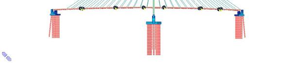
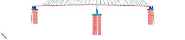
Építési állapotok (Midas
1. Építési fázis: Aléptmények éptése, merevítőtartók beemelése állványokra hosszirányban kéttámaszústva, merevítőtartó elemek összehegesztése állványokon. Pilon építés egy kitámasztás benntartásával feszítés előtt, a pilont kitámasztó rúd szelvénye Φ800x40. Jármok helyeit lásd a tervlapokon.
Végeselemes
rúd szelvénye Φ800x40. Jármok helyeit lásd a tervlapokon.
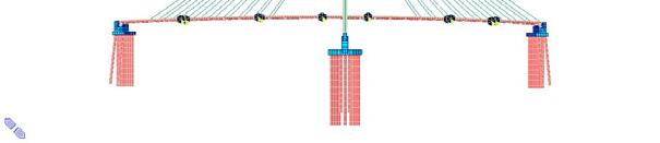
7. Építési fázis: Pilont hátrahorgonyzó fölső két kábel megfeszítése, alulról felfelé haladva.
CABLES


SPECIÁLTERV Építőmérnöki Kft.
5. Építési fázis: A pilont hátrahorgonyzó legalsó kábel megfesztése.
SPECIÁLTERV Építőmérnöki Kft.
STATIKAI SZÁMÍTÁS – Osztószigeti gyalogos híd
7. ábra – 1. Építési fázis
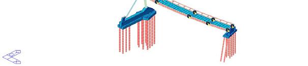
2. Építési fázis: A merevítőtartó kibetonozása a betonozási támaszokon.
SPECIÁLTERV Építőmérnöki Kft. STATIKAI SZÁMÍT

5. Építési fázis: A pilont hátrahorgonyzó legalsó kábel megfesztése.
STATIKAI SZÁMÍTÁS – Osztószigeti gyalogos híd
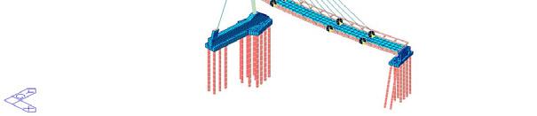
3. Építési fázis: 5-5 db pilon felőli kábel megfeszítése párosával, a rövidebbektő a hosszabbak felé haladva.
SPECIÁLTERV Építőmérnöki

STATIKAI SZÁMÍT
3. Építési fázis: 5-5 db pilon felőli kábel megfeszítése párosával, a rövidebbektől a hosszabbak felé haladva.
Számította: Dési Attila
4.
11. ábra – 5. Építési fázis
13. ábra – 7. Építési fázis
8. Építési fázis: Pilonnal átellenes oldalon lévő kábelek feszítése párosával, a hosszabbaktól a rövidebbek felé haladva, addig amíg utolérjük a pilon felöli kábeleket.
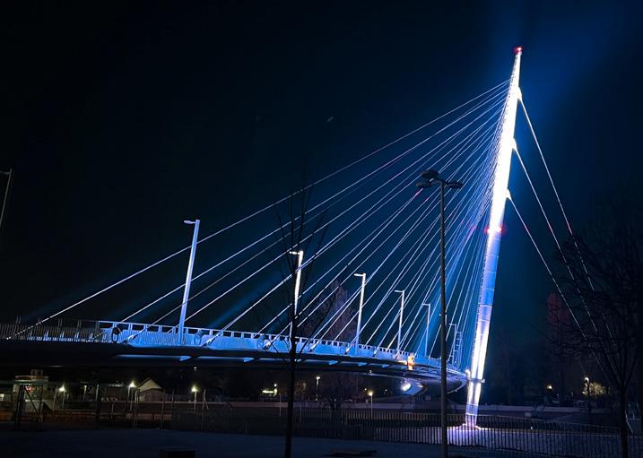
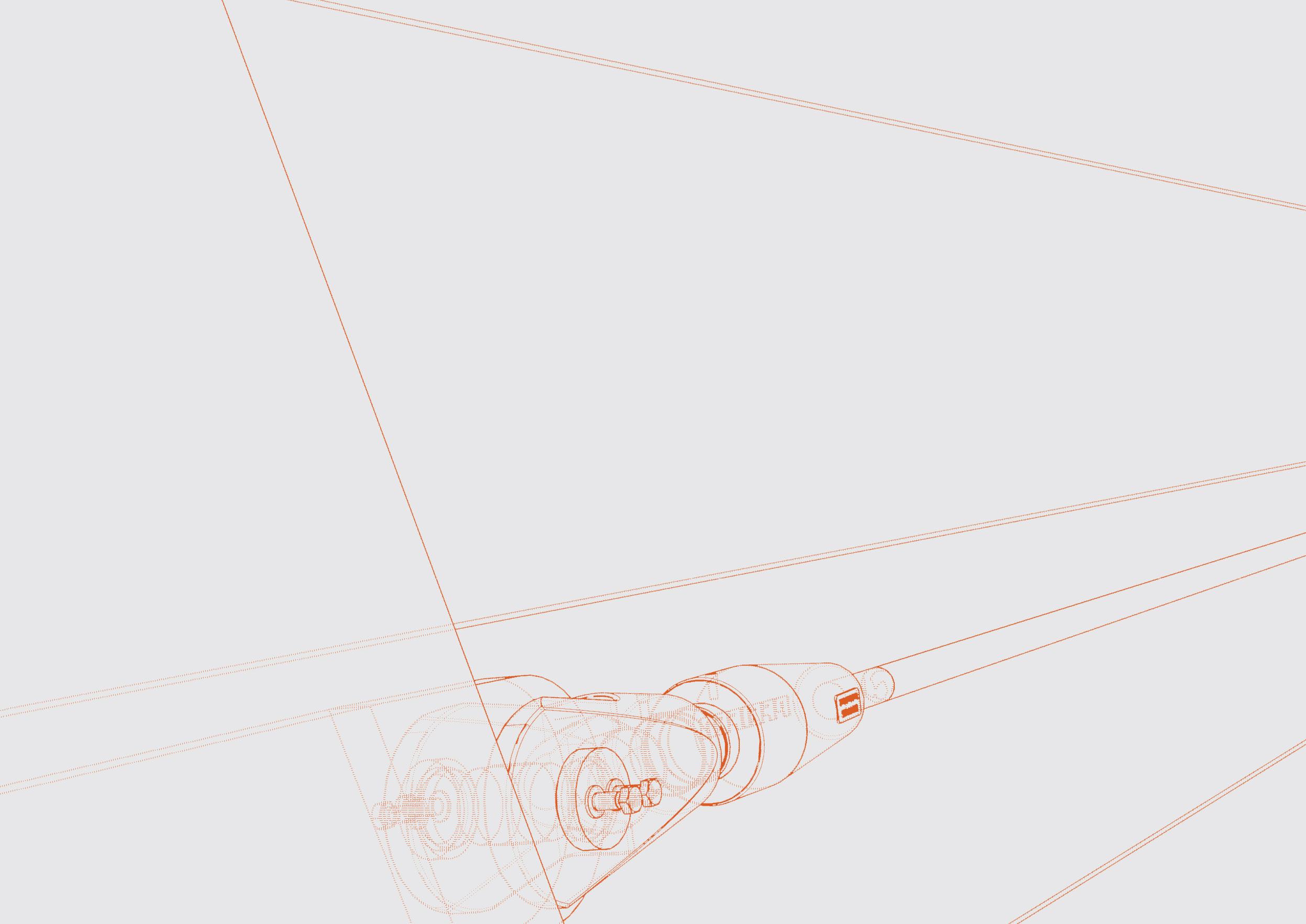
The slender curved deck, which is nearly 170 m long, “floats” over the Danube branches without any additional support. The deck is suspended with 53 high strength steel full-locked coil ropes attached to a needle-like pylon independent of the deck. Their diameters range from 35 to 65 mm, with 5 mm increments. The equilibrium of the outward-leaning slender pylon is ensured by the three backstay cables anchored to the support located on the island. 100 mm nominal diameter cables were used for this. All stay cables have adjustable forked ends.


SPECIÁLTERV Építőmérnöki Kft. STATIKAI SZÁMÍTÁS – Osztószigeti gyalogos híd
SPECIÁLTERV Építőmérnöki Kft. STATIKAI SZÁMÍTÁS – Osztószigeti gyalogos híd
9. Építési fázis: A maradék kábel megfeszítése párosával a hídfőktő a pilon felé haladva. (2db kábel pilon oldalon, 2db átellenes oldalon, 2db kábel pilon oldalon, …, 1db pilonnal átellenes középső kábel)
9. Építési fázis: A maradék kábel megfeszítése párosával a hídfőktő a pilon felé haladva. (2db kábel pilon oldalon, 2db átellenes oldalon, 2db kábel pilon oldalon, …, 1db pilonnal átellenes középső kábel)

14. ábra – 8. Építési fázis
6. Építési fázis: Maradék pilon felőli kábelek megfeszítése párosával, a rövidebbektő a hosszabbak felé haladva.
SPECIÁLTERV Építőmérnöki Kft.
STATIKAI SZÁMÍTÁS – Osztószigeti gyalogos híd
15. ábra – 9. Építési fázis
12. ábra – 6. Építési fázis
7. Építési fázis: Pilont hátrahorgonyzó fölső két kábel megfeszítése, alulról felfelé haladva.
10. Építési fázis: Jármok bontása, korlátok építése.
15. ábra – 9. Építési fázis
Számította: Dési Attila
13. ábra – 7. Építési fázis
Számította: Dési Attila - 15 -
8. Építési fázis: Pilonnal átellenes oldalon lévő kábelek feszítése párosával, a hosszabbaktól a rövidebbek felé haladva, addig amíg
16. ábra – 10. Építési fázis
16. ábra – 10. Építési fázis
Számította: Dési Attila
Civil)
szoftverben a következő építési állapotokat állítottuk be:
1. Építési fázis: Aléptmények éptése, merevítőtartók beemelése állványokra hosszirányban kéttámaszústva, merevítőtartó elemek összehegesztése állványokon. Pilon építés egy kitámasztás benntartásával feszítés előtt, a pilont kitámasztó
7. ábra – 1. Építési fázis
8. ábra – 2. Építési fázis
Kft.
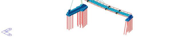
10. ábra – 4. Építési fázis
9. ábra – 3. Építési fázis
Építési fázis: A pilont kitámasztó rúd bontása
10. ábra – 4. Építési fázis
utolérjük a pilon felöli kábeleket.
20

21

22
BRIDGE ACCESSORIES
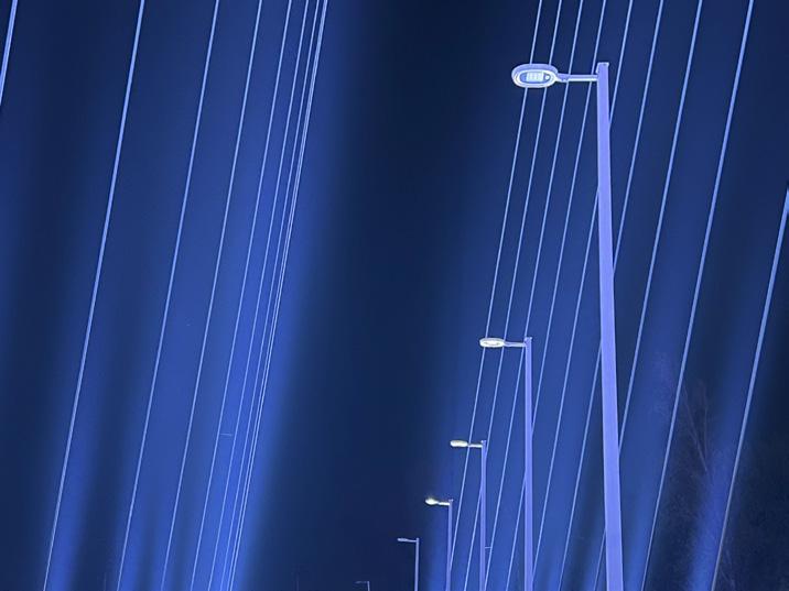
The bridge railings are tilted to match the path of the stay cables towards the pylon. This effect also emphasizes the spatial curvature of the bridge deck and the inclination of the pylon. The handrails running at heights of 1.00 and 1.40 m are made of tubular sections. The railings are also designed to withstand an accidental collision force to protect electric cars that may occasionally appear on the bridge during larger sports events. The bridge deck is illuminated by 8 m high lamp posts placed at 18 m intervals on the pylon side.
Sections of different railing variations
Lighting
23


24

25

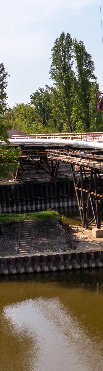
BUILDING TECHNOLOGY
Pile cap side view, with temporary works
26
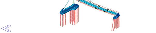
Pylon erection - stage 0
CONSTRUCTION TECHNOLOGY

In order to achieve our objective, all participants of the project provided the best of their professional knowledge. Due to the extremely complex shape of the structure, planning, production, and construction could not have been realized without state-of-the-art software, procedures and BIM models that enable 21st century 3D and 4D planning.
Designing and constructing cable-stayed structures is among the greatest challenges in the field of civil engineering. The construction of a slender, curved, asymmetric cable-stayed bridge involves dealing with significant deformations, which is a serious task for both designers and contractors to control. In the case of ‘Robinson’ Bridge, this difficulty was successfully overcome by close collaboration between the designers and contractors using a measurement-evaluation-control process aided by parametric design.
The designed pylon and the bridge deck are both extremely slender, which was ensured by the combined and economical use of steel structure and concrete. The pylon and the parts of the superstructure in which its advantages could be utilized were designed and fabricated from high-strength and thermomechanically rolled S460 M/ML steel material, which is not yet common in bridge construction, and requires special attention during design and fabrication. To this end, a number of unique manufacturing and welding technologies were used.
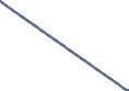
Assembling the steel structure of the pylon on barge and lifting it together with a 200t floating crane was one of the most spectacular and complicated operations of the construction, which was able to be realized effortlessly and with almost incredible precision within just a few hours as a result of almost a year of careful preparation. The interior of the steel pylon and parts of the bridge deck were filled with concrete. The composite action between steel and concrete was an efficient and economical design solution to increase the performance and durability of the main load bearing elements.
As a consequence of the curvature of the deck and the inclined stay cables, significant lateral force is required to keep the bridge deck in position. A special arrangement of 3 bearing at each abutment were designed.
 Pylon erection - stage 1
Pylon and auxiliary column connection
Pylon erection - stage 1
Pylon and auxiliary column connection
27
Pylon erection - stage 2

MODE ABUTMENT
A tervdokumentáció szerzői jogról szóló 1999. évi LXXVI. tv. védelme alatt áll. Méretarány: Tervfajta: MEGJEGYZÉSEK, JELMAGYARÁZAT REVÍZIÓ Szám: Leírás: Dátum: Kvassay Jenő út Rákóczi híd Duna által határolt terület PROJEKT INFO BUDAPESTI ATLÉTIKA STADION SPECIÁLTERV ÉPÍTŐMÉRNÖKI KFT. 1134 Budapest Kassák Lajos utca 81. Tel.: +36 368 9107, E-mail: specialterv@specialterv.hu ÉPÍTŐMÉRNÖKI KFT SZAKÁGI TERVEZŐ Helyrajzi szám: Projekt: Helyszín: Építtető: Név: 38086/78 GENERÁLKIVITELEZŐ Vállalkozó: ZÁÉV Építőipari Zrt. 8900 Zalaegerszeg, Millennium Köz 1. Tel.: +36 92 504 100, E-mail: zaev@zaev.hu Magyar Építő Zrt. 1149 Budapest, Pillangó utca 28. Tel.: +36 1 467 2700, E-mail: info@magyarepito.hu Vállalkozó: KIVITELEZŐ Hídépítő Zrt. 1138 Budapest, Karikás Frigyes utca 20. Tel.: +36 1 465 2200, E-mail: info@hid.hu Kivitelező: BMSK Beruházási, Műszaki Fejlesztési, Sportüzemeltetési és Közbeszerzési Zrt. 1146 Budapest, Istvánmezei út 1-3. Tel.: +36 1 325 1750, E-mail: info@bmsk.hu Felelős tervező: Pataki Péter T 01-5232 Mészáros Norbert Tervező: Tervező: Tervező: Ellenőr: Szabados Mihály Kemenczés András Hunyadi László HT 01-12467 TECHNOLÓGIAI TERV OSZTÓSZIGETI GYALOGOS HÍD 000 BÍRÁLATRA 2021.04.12 M = 1:20, 1:10 28
29

30
31
32
EXCELLENCE IN DESIGN
Aesthetic appearance was given a prominent role throughout the implementation of the project, since our goal was to create an elegant and innovative bridge structure in both domestic and international perspective which can live up to the very high expectations regarding the famous Budapest cityscape, the valuable waterfront of the Danube River, and also the Stadium complex itself.
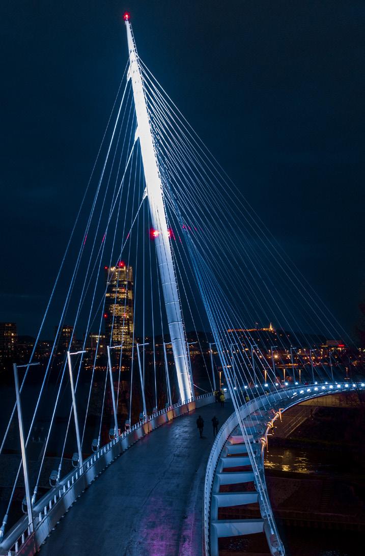
In the architectural design of the bridge and stadium, we had to choose between similarity and differentiation. Ultimately, we have concluded on contrast, with the stadium’s curved and flat mass opposing the bridge’s pointed, angular and tall, yet very transparent structure. While the two facilities allude to each other in their details, they complement each other perfectly as a whole.
The pylon is elegantly slim and needle-like, suspending the bridge deck without any intermediate support to achieve a floating effect. The transparent cable network reveals a new and exciting experience from every angle, focusing the user’s attention towards the sky.

41
linkedin.com/ specialterv-kft
facebook.com/ specialterv
specialterv.com/projects/ bridges/robinsonbridge
+ 36 1 368 9107
1134 Budapest, Kassák Lajos utca 81. specialterv@specialterv.hu
SOURCES:
All illustrations and plans: SPECIÁLTERV
Cover image: Magyar Építők
Images on pg. 9-14, 20-23 and 30: Magyar Építők
Images on pg. 19, 32-33, image 2 and 3 on pg. 37, and pg. 38: SPECIÁLTERV

 Edited by SPECIÁLTERV SPT-ROB-V2-2305