
HULLÁMOK JÁTÉKA FLOW OF THE WAVES BICYCLE ROAD BRIDGES BETWEEN POROSZLÓ AND TISZAFÜRED A POROSZLÓ-TISZAFÜRED KÖZÖTTI KERÉKPÁRÚT HÍDJAI


Bicycle
1 HULLÁMOK JÁTÉKA A Poroszló–Tiszafüred közötti kerékpárút hídjai
FLOW OF THE WAVES road bridges between Poroszló and Tiszafüred
2
Szerkesztette: Speciálterv Kft. 1134 Budapest, Kassák Lajos u. 81. Pál Gábor/Salánki Balázs/Zalai Tamás/Dési Attila/ Kemenczés András/Wunderlich István/Tóth Miklós/Borzai Tibor Felelős szerkesztő: Borzai Tibor Kiadja: Hidászokért Egyesület 2045 Törökbálint, Kossuth Lajos u. 6. Felelős vezető: Sitku László ISBN 978-615-01-2816-0Készült: TEXT Nyomdaipari Kft. 2400 Dunaújváros, Papírgyári út 49. Telefon: 25/283-019 Kiadványszerkesztés: Knyihárné Fülöp Andrea Felelős vezető: Knyihár Lajos
3 HULLÁMOK JÁTÉKA A Poroszló–Tiszafüred közötti kerékpárút hídjai FLOW OF THE WAVES Bicycle road bridges between Poroszló and Tiszafüred
88 2 4
84 2 .2 .
The structural elements of the structure . . . The water regulating structure and it’s reconstruction . . . . . . . . . . . . . . 64 Use of the current structure as abutments 64 The designed bridge . . . . . . . . . . . . . . . . 66 The operation of the bridge . . . . . . . . . . 66 Mechanical engineering . . . . . . . . . . . . 66 III. CONSTRUCTION – HÓDÚT KFT. . . . . . . . . . . . . 70 . EGER AND SZOMORKA CREEK BRIDGES . . . . . . . 70 1 1 History, organization 70 1 2 . Substructures . . . . . . . . . . . . . . . . . . . . 70 1 3 Manufacturing 72 1 4 . On-site installation . . . . . . . . . . . . . . . . . 78 2 . TISZA BRIDGE . . . . . . . . . . . . . . . . . . . . . 84 2 .1 History, organization . . . . . . . . . . . . . . . . Substructures, cantilevers . . . . . . . . . . . transportation . . . . . . . . . . . . . . . . . . . Designing technology, pre-assembly .2 of the deck of the barges . . 94 the bridge elements onto the barges and lifting them into place . . . . . . . . . . . . . . . . . . . 106 .1 Dynamic test loading . . . . . . . . . . . . . . . . 106 .2 . Static test loading . . . . . . . . . . . . . . . . . . 110 BRIDGES . . . . . . . . . . . . . . . . 112 . CREEK BRIDGE . . . . . . . . . . . . . . . . . . . SZOMORKA CREEK BRIDGE . . . . . . . . . . . . . . BRIDGE BRIDGE OF THE FLUSHING NO . X . . . . . . . . . . . . . . . . . . . . CLOSING REMARKS . . . . . . . . . . . . . . . . . . . participated in the implementation . . . . . . . . . . . . . . . . . . . . . . . . . . . . . . . . . .
64
the
EGER
134 4 . OPENABLE
CHANNEL
154 Organizations
128 3 TISZA
84 2 3 Manufacturing,
156 Photos and Figures 157 List of Photos
IV. THE REALIZED
86 2 .4 On-site assembly
112 2 .
88 2 4 1
146 V.
4
4 I. DEMAND, LOCATION . . . . . . . . . . . . . . . 6 1 . LOCATION . . . . . . . . . . . . . . . . . . . . . . 6 1 1 . The birth of the Lake Tisza . . . . . . . . . . 8 1 2 Parts of the Lake 8 1 3 . The environmental characteristics of the lake 8 1 3 1 The topography of the area 8 1 .3 .2 . Hydrographic characteristics . . . . . . . 10 1 3 3 The water protection of Lake Tisza 10 1 .3 .4 . Wildlife . . . . . . . . . . . . . . . . . . . 10 2 HISTORY . . . . . . . . . . . . . . . . . . . . . . . . 14 3 . THE PURPOSE OF THE CONSTRUCTION . . . 14 4 THE SECTION BETWEEN POROSZLÓ AND THE TISZA BRIDGE . . . . . . . . . . . . . . 16 5 THE SECTION BETWEEN THE TISZA BRIDGE AND TISZAFÜRED . . . . . . . . . . . . . . . . . . . 16 II. PLANNING – SPECIÁLTERV KFT. . . . . . . . . . 20 1 . CONCEPT PLANNING, STUDIES . . . . . . . . . 20 The bridges of Eger and Szomorka creeks . . . . . 22 The widening of the Tisza Bridge in Tiszafüred 26 A Tisza-tavi hidak végleges formája . . . . . . . . . . 32 2 EGER AND SZOMORKA CREEK BRIDGES . . . . . 34 Authorization plans . . . . . . . . . . . . . . . . . . . 34 Construction plans . . . . . . . . . . . . . . . . . . . 38 Substructures . . . . . . . . . . . . . . . . . . . . 38 Superstructures . . . . . . . . . . . . . . . . . . . 40 Statics . . . . . . . . . . . . . . . . . . . . . . . . . . 42 Dynamics . . . . . . . . . . . . . . . . . . . . . . . 46 3 . TISZA BRIDGE . . . . . . . . . . . . . . . . . . . 50 3 1 The existing, truss composite bridge 50 3 2 . The designed bicycle bridge . . . . . . . . . . 52 Using an existing structure as intermediate supports . . . . . . . . . . . . . . . . . . . . 52 Abutments . . . . . . . . . . . . . . . . . . . . 56 SUPERSTRUCTURE . . . . . . . . . . . . . . 56 Deck plate, bracing bracket . . . . . . . . . . 56 Floodplain bridges, tensioning structure . 56 Riverbed bridges, arch holder . . . . . . . . . 56 Static behavior 58 4 THE STRUCTURE OF THE FLUSHING CHANNEL NO . X . . . . . . . . . . . . . . . . . . . . . . . . . 62 4 .1 Movable bridges . . . . . . . . . . . . . . . . . . 62 4 .2 . Designing . . . . . . . . . . . . . . . . . . . 62
1
Equipment
96 3 THE OPENABLE BRIDGE OF THE FLUSHING CHANNEL NO X 104 4 TEST LOADING .
4
158 List of Figures 162 CONTENTS
1
2 4 3 Moving
5 TARTALOM I. IGÉNY, HELYSZÍN 7 1. HELYSZÍN 7 1.1. A Tisza-tó születése ......................... 9 1.2. A tó részei 9 1.3. A tó környezeti jellemzői .................... 9 1.3.1. A terület domborzati adottságai ........ 9 1.3.2. Vízrajzi jellemzők 9 1.3.3. A Tisza-tó vízvédelmi bemutatása ....... 11 1.3.4. Élővilág 11 2. ELŐZMÉNYEK ................................. 15 3. AZ ÉPÍTÉS CÉLJA ............................... 15 4. POROSZLÓ TISZA-HÍD KÖZÖTTI SZAKASZ 17 5. TISZA-HÍD TISZAFÜRED KÖZÖTTI SZAKASZ 17 II. TERVEZÉS – SPECIÁLTERV KFT. ............. 21 1. KONCEPCIÓTERVEZÉS, TANULMÁNYOK .......... 21 Eger- és Szomorka-patak-hidak 23 A Tiszafüredi Tisza-híd szélesítése ................ 27 A Tisza-tavi hidak végleges formája 33 2. EGER- ÉS SZOMORKA-PATAK-HIDAK . . . . . . . . . . . . . . 35 Engedélyezési tervek ........................... 35 Kiviteli tervek 37 Alépítmények .................................. 37 Felszerkezetek 41 Statika ........................................ 41 Dinamika 47 3. TISZA-HÍD ..................................... 51 3.1. Meglévő, rácsos öszvérhíd ................... 51 3.2. Tervezett kerékpároshíd 53 A jelenlegi műtárgy felhasználása közbenső támaszokként 53 Hídfők .................................... 57 FELSZERKEZET 57 Pályalemez, merevítőtartók .................. 57 Ártéri hidak, feszítőmű 57 Mederhidak, ívtartó ......................... 57 Statikai viselkedés 59 4. X. SZ. ÖBLÍTŐCSATORNA MŰTÁRGYA 63 4.1. Mozgatható hidak .......................... 63 4.2. Tervezés 65 A vízépítési műtárgy és rekonstrukciója ....... 65 A jelenlegi műtárgy felhasználása hídfőkként 65 A tervezett híd ............................. 67 A híd kezelése 69 Gépészet .................................. 69 III. KIVITELEZÉS – HÓDÚT KFT. 71 1. EGER- ÉS SZOMORKA-PATAK-HIDAK . . . . . . . . . . . . . . 71 1.1. Előzmény, organizáció ...................... 71 1.2. Alépítmények 71 1.3. Gyártás .................................... 73 1.4. Helyszíni szerelés 79 2. TISZA-HÍD 85 2.1. Előzmény, organizáció ...................... 85 2.2. Alépítmények, konzolok 85 2.3. Gyártás, szállítás ............................ 87 2.4. Helyszíni szerelés . . . . . . . . . . . . . . . . . . . . . . . . . . . 89 2.4.1. Technológia tervezése, előszerelés ...... 89 2.4.2. A bárkafedélzetek berendezése 95 2.4.3. Hídelemek mozgatása bárkákra és beemelés ........................... 97 3. X. SZ. ÖBLÍTŐCSATORNA NYITHATÓ HÍDJA 105 4. PRÓBATERHELÉS 107 4.1. Dinamikus próbaterhelés .................... 107 4.2. Statikus próbaterhelés 109 IV. MEGVALÓSULT HIDAK ...................... 113 1. EGER-PATAK HÍDJA ............................. 113 2. SZOMORKA-PATAK HÍDJA 129 3. TISZA-HÍD 135 4. X. SZ. ÖBLÍTŐCSATORNA NYITHATÓ HÍDJA ....... 147 V. ZÁRSZÓ 155 A megvalósítás során közreműködő szervezetek 156 Képek, ábrák ......................................... 157 Képek jegyzéke 159 Ábrajegyzék .......................................... 163
1 LOCATIONDEMAND, LOCATION 1. kép: A Tisza-tó látképe / Picture 1.: View of Lake Tisza I. DEMAND, LOCATION 1. Location I

1HELYSZÍN IGÉNY, HELYSZÍN 2. kép: A 33. sz. főút keresztezése a Tisza-tavon / Picture 2.: Crossing of road number 33 on Lake Tisza I. IGÉNY, HELYSZÍN 1. Helyszín I

In the surroundings of Lake Tisza, the typical altitude is between 85 and 90 m above sea level . The relative relief is of very little value, the largest level difference nowhere exceeds 2 m/square kilometres . Its northern part (Borsod floodplain) varies between 87.3 and 98.1 m above sea level . The average relative relief value here is
The present appearance of the area is fundamentally determined by the work of generations of civil engineers of the earlier ages who’s work was built on each other . In the second half of the 19th century, the river regu lation planned by Pál Vásárhelyi transformed the river Tisza and its surroundings, thus creating the flood pro tection lines that still bordering the river . Later, with the construction of the dam at Kisköre, between 1967 and 1974, the Lake Tisza was created by damming back the river – originally called the Kisköre Reservoir – and became the largest artificial lake in Hungary.
8 1.1. The birth of the Lake Tisza
The floodplain of the reservoir is located in the sec tion between the 404 and 440 river kilometer sections of the river Tisza, between Kisköre and Tiszabábolna, covering a total area of 127 square kilometers The low land area that was previously used for farming was flooded in many stages, the today’s water coverage of the lake in summer time was formed in 1978 . Since then, in the more than 40 years that have passed, a diverse, uniquely rich fauna has gradually developed with en vironmental conditions that are similar to the ancient Tisza floodplain landscape.
The water depths of the pools and bays are very var ied. Next to the large, nearly flat areas, it is 0.8 m to 2 .0 m deep, the water depth of natural watercourses, backwaters and irrigation canals is between 2 .0 and 5 .0 m, and the greatest, 10–20 m depths can be meas ured in the main riverbed .
1.2. Parts of the Lake Lake Tisza is divided into five larger basins: – Tiszavalk Basin – Poroszló Basin – Tiszafüred Basin – Sarud Basin – Abádszalók Basin
The second largest still water of the Carpathian Basin is located on the river Tisza, at its lowland section, on the border of Jász-Nagykun-Szolnok and Heves counties .
Today, large areas of open water, wetlands overgrown with swamp and seaweeds, backwaters, morotvas, nat ural watercourses, capes, flushing canals, islands and peninsulas make the area diverse and unique .
The internal flow system of the basins is fed by the rinsing channels, which establish the connection be tween the river Tisza as the main riverbed and its floodplain as a reservoir (lake). In its natural state, the coastal strip (belt reef) surrounding the riverbed is con stantly filled, stands out and does not allow the refresh ing water coming from the river to spread . The rins ing channels are ensuring the supply, distribution and drainage of the refreshing water to pools formed by belt reefs . 1.3. The characteristicsenvironmentalofthe lake 1.3.1. The topography of the area
I DEMAND, LOCATION 1 Location
A medencék és öblözetek vízmélysége igen változatos. A nagy kiterjedésű, közel sík területeken 0,8 m 2,0 m, a természetes vízfolyások, holtágak és öblítő csatornák vízmélysége 2,0–5,0 m közötti, a legnagyobb mélységek pedig a főmederben mérhetőek, 10–20 m.
A medencék belső áramlási rendszerét az öblítőcsatornák táplálják, melyek megteremtik a kapcsolatot a Tisza folyó, mint főmeder és hullámtere, mint tározótér (tó) között. A medret övező parti sáv (övzátony) természetes állapotában folyamatosan töltődik, kiemelkedik, és nem teszi lehetővé a folyón érkező frissítő víz szétterülését. Az öblítőcsatornák a frissítő víz bejuttatását, szétosztását, ill. elvezetését biztosítják az övzátonyokkal kirekesztett medencékbe.
A Tisza-tó környezetében 85 és 90 m közötti tszf-i magasság a jellemző. A relatív relief nagyon kis értékű, a legnagyobb szintkülönbség a 2 m/km2-t sehol sem haladja meg. Északi (Borsodi ártér) része 87,3 és 98,1 m tszf között változik. Az átlagos relatív relief értéke itt 1 m/km2. A felszín legnagyobb része alacsony ártéri és ármentes síkság, északi részén ármentes részekkel tagolt, de egészében ártéri szintű tökéletes síkság. 1.3.2. Vízrajzi jellemzők
1.3. A tó környezeti jellemzői
A Kárpát-medence második legnagyobb állóvize a Tisza folyón, annak alföldi szakaszán, Jász-Nagykun-Szolnok és Heves megye határán helyezkedik el. A terület mai megjelenését alapvetően meghatározza a korábbi korok építőmérnök nemzedékeinek egymásra épülő munkássága. A XIX. század második felében a Vásárhelyi Pál által tervezett folyószabályozás formálta át a Tiszát és környezetét, létrehozva a folyót ma is határoló árvízvédelmi védvonalakat. Később a Kiskörei vízlépcső 1967 és 1974 közötti megépítésével, a folyó visszaduzzasztásával jött létre a Tisza-tó – eredeti nevén a Kiskörei víztározó – hazánk legnagyobb mesterséges tava. A tározó hullámtere a Tisza folyó 404 és 440 folyamkilométer-szelvényei közötti szakaszon, Kisköre és Tiszabábolna között terül el, összesen 127 km2-en. A korábban gazdálkodásra használt síkvidéki területet több ütemben árasztották el, a tó mai nyári vízborítottsága 1978-ban jött létre. Az azóta eltelt több mint 40 évben fokozatosan fejlődött ki egy változatos, az ősi ártéri Tisza-tájhoz hasonló környezeti adottságokkal rendelkező, páratlanul gazdag élővilág. Napjainkban nagy kiterjedésű nyílt vízfelületek, mo csári és hínári növényzetekkel benőtt vizes területek, holtágak, morotvák, természetes vízfolyások, fokok, öblítőcsatornák, szigetek és félszigetek tarkítják, teszik változatossá és egyedivé a területet. 1.2. A tó részei
A Tisza-tó öt nagyobb medencére tagolódik: – Tiszavalki-medence, – Poroszlói-medence, – Tiszafüredi-medence, – Sarudi-medence, – Abádszalóki-medence.
A Tisza-tó mesterséges létesítmény, lényegében egy átfolyásos tározó, szintjének helyzete a folyó mindenkori vízjárásának is függvénye. A duzzasztómű csak a kiskörei szelvényben tartja a vízszintet egy adott intervallumon belül, a tározó felszínének esése az érkező vízhozamtól függ.
I. IGÉNY, HELYSZÍN 1. Helyszín
1.3.1. A terület domborzati adottságai
9 1.1. A Tisza-tó születése
1.3.4. Wildlife
3.
tion canals of Jászság (with a capacity: 48 m3/sec) and Nagykunság (with a capacity: 80 m3/sec), which ensure the supply of irrigation water and the refillment of fish ponds in the surrounding areas . In addition to satis fying agricultural water needs, the Nagykunság main canal, by gravity water transmission plays a major role in alleviating the water shortage and ecological water replenishment of the Körös Valley .
The first protected area of Lake Tisza is the Tiszafüred Bird Sanctuary situated in the Valki Basin, which was established in 1972 on 3,400 hectares . The nature con servation area was declared as the part of the Hortobágy National Park in 1993, and it was expanded by 3,600 hectares by declaring the Poroszló and Sarudi basins partially protected . Protected natural areas of national importance are also so-called wetlands of international importance that are covered by the Ramsar Conven tion, and as part of the Hortobágy National Park, they have been a UNESCO World Heritage Site since 1999 . The entire area of Lake Tisza is part of the European Union’s nature conservation network, the so-called Natura 2000 network, as a priority nature conservation and special bird protection area .
1.3.3. The water protection of Lake Tisza
Lake Tisza is the second largest lake in Hungary, which belongs to the Nagykunság subunit from the point of view of the river’s drainage basin management . The liv ing river Tisza flows through the lake on a 33 km long section . In the vicinity of Lake Tisza a numerous des ignated water base protecting defender areas/defender profiles can be found.
A special feature of the lake is that its stream is con trollable. The river Tisza flows through the reservoir area in an independent riverbed – the main riverbed or the so-called mother riverbed . Parallel to the main riverbed, to its right and left, is the line of belt reefs — these form the system of islands and peninsulas — that separates the riverbed from the reservoir basins
10 1 m/square kilometer. Most of the surface is low flood plain and flood-free plain areas, In it’s northern part, it is divided by flood-free parts, but on the whole flood plain level, a perfect plain .
kép: Madárvilág / Picture 3 .: Birdlife I DEMAND, LOCATION 1 Location

Lake Tisza is an artificial facility, essentially a flowthrough reservoir, the position of it’s water level also depends on the current stream of the river . The dam keeps the water level within a certain interval only in the Kisköre section, the hang of the reservoir surface depends on the flow of the incoming water.
The current volume of the reservoir is 253 million cubic metres, of which 132 million cubic metres can be utilized . The most important facilities of the water distribu tion network of the water supply are the main irriga
1.3.2. Hydrographic characteristics
A tó sajátossága, hogy vízjárása szabályozható. A Tisza folyó önálló mederben – főmeder, vagy úgynevezett anyameder – folyik át a tározótéren. A főmederrel párhuzamosan, annak jobb és bal oldalán húzódik az övzátonyok vonulata – ezek alkotják a szigetek és félszigetek rendszerét –, amely elválasztja a folyó medrét a tározó medencéitől. A tározó jelenlegi térfogata 253 millió m3, melyből 132 millió m3 hasznosítható. A vízkészlet vízelosztó hálózatának legfontosabb létesítményei a Jászsági (kapacitása: 48 m³/sec) és a Nagykunsági (kapacitása: 80 m3/sec) öntöző főcsatornák, amelyek biztosítják a környező térségek öntözővíz ellátását és halastavi vízpótlását. A Nagykunsági főcsatorna a mezőgazdasági vízigények kielégítése mellett, gravitációs átvezetéssel nagy szerepet játszik a Körös-völgy vízhiányának enyhítésében és ökológiai vízpótlásában. 1.3.3. A Tisza-tó A Tisza-tó Magyarország második legnagyobb tava, amely vízgyűjtő-gazdálkodási szempontból a Nagykun sági alegységhez tartozik. A tóban egy 33 km-es szakaszon folyik át az élő Tisza. A Tisza-tó környezetében számos kijelölt, vízbázis-védelmi védőterület/védőidom található. 1.3.4. Élővilág
bemutatásavízvédelmi
A Tisza-tó első védett területe a Valki-medencében elhelyezkedő tiszafüredi madárrezervátum, melyet 1972ben alapítottak 3400 hektáron. A természetvédelmi területet 1993-ban a Hortobágyi Nemzeti Park részévé nyilvánították, majd 3600 hektárral kibővítették a Poroszlói- és Sarudi-medencék részleges védetté nyilvánításával. Az országos jelentőségű védett természeti területek egyben a Ramsari Egyezmény hatálya alá tartozó, ún. nemzetközi jelentőségű vizes élőhelyek, valamint a Hortobágyi Nemzeti Park részeként 1999 óta az UNESCO világörökség részei. A Tisza-tó egész területe az Európai Unió természetvédelmi hálózatába, az ún. Natura 2000 hálózatba tartozik, mint kiemelt jelentőségű természet-megőrzési és különleges madárvédelmi terület. A tó egyes részei emellett a Hortobágyi Nemzeti Park bemutatóterületei. 4–5. kép: Madárvilág / Picture 4–5 .: Birdlife

I. IGÉNY, HELYSZÍN 1. Helyszín

Lake Tisza is a significant bird habitat in all seasons, with more than 200 species observed in and around the lake . In spring and summer, nesting birds cover the lake . The heron colony of the Tiszafüred Bird Sanctuary is unique, in which the pygmy cormorant, little egret, great egret, gray heron, black-crowned night heron nest. The undisturbed floodplain forests are nested by the white-tailed eagle, the black kite and the black stork . In addition to nesting, the lake also plays a prominent role in bird migration . Hundreds of thousands of water birds visit the lake in autumn and winter . In addition to the masses of wild ducks and great white-fronted gooses, Lake Tisza plays a prominent role in the mi gration of common pochards, tufted ducks and com mon goldeneyes, but the highly protected red-breasted goose is also resting in increasing numbers on the lake . The presence of velvet ducks or velvet scoters, which cross the lake are sporadic in Hungary, and are unique in relation to the Great Plain . Along the cycle path, many bird species can be observed from close on the Lake Tisza Water Promenade and Educational Trail . Singing birds and bearded reedlings live in the reeds, and almost all water birds on the lake occur along the open waters . Typical bird species of the domestic sum mers along the trail are the common wood pigeon, the great spotted woodpecker, the Eurasian blackcap, the common chiffchaff and the great tit .
.
Among mammals, the retreating beaver is becom ing more common in the area, but otters and wildcats also occur . In the bumpier parts, on islands, roe deers and wild boars have also found favorable conditions for their living .
.
12 Besides this, some parts of the lake are also demon stration areas of the Hortobágy National Park
I DEMAND, LOCATION 1 Location
The lake hides a unique world of the wild water, at tracting hikers and tourists to an adventurous journey, offering different leisure time opportunities in every season . We can choose between routes and explore the countryside on foot, by bike, on horseback, or even by boat throughout the whole year . Thanks to the diverse habitats and mosaic-like struc ture of Lake Tisza, a very rich fauna has developed here . They are accounting 14 types of plant associations in its territory . Along the cycle path, the number of natural and natural-like habitats is small Starting from Poroszló, the open water is mainly characterized by seaweed asso ciations formed by fringed water lily, white water lily, yellow pond-lily and water caltrop . Common species in the shallower parts are diamond milfoil, bladderwort, common club-rush and flowering rush. A narrow strip along the shores is occupied by broadleaf cattails and reeds . The dominant species in the wooded areas is the native white poplar and white willow, but along the bike path, alien invasive species such as green ash, boxelder maple, or false indigo bush have also spread . The under growth of floodplain forests is poorer, but the protected summer snowflake occur in several places. The fish fauna of Lake Tisza is extremely rich, with more than 50 species known to occur, of which the bream, carp, silver carp, fluvial catfish and pike are common . Fishing is allowed in accordance with the rulesThe. most common amphibians are marsh frogs, pool frogs and edible frogs, but European fire-bellied toads and European tree frogs are also common, while the Danube crested newt is rarely seen . Reptiles are repre sented by the grass snake and the European pond turtle
A fészkelésen túl a tó szerepe a madárvonulásban is kiemelkedő. Ősszel és télen vízimadarak százezrei keresik fel a tavat. A tőkés récék és nagy lilikek tömegei mellett a Tisza-tónak kiemelkedő szerepe van a barát-, kontyos és kercerécék vonulásában, de a fokozottan védett vörösnyakú lúd is egyre nagyobb számban pihen meg a tavon. Alföldi viszonylatban egyedülálló a tavon átvonuló, hazánkban szórványosan előforduló búvárok vagy füstös récék jelenléte. A kerékpárút mentén a Tisza-tavi Vízi Sétányon és Tanösvényen számos madárfaj közelről is megfigyelhető. A nádasokban nádi énekesek és barkóscinegék élnek, a nyílt vizek mentén pedig a tavon előforduló szinte összes vízimadár előfordul. A nyomvonal menti hazai nyarasok jellemző madárfajai az örvös galamb, a nagy fakopáncs, a barátposzáta, a csilpcsaplfüzike és a széncinege. Emlősök közül a visszatelepülő hód egyre gyakoribb a területen, de előfordul a vidra és a vadmacska is. A hátasabb részeken, szigeteken az őzek és vaddisznók is megtalálták az élőhelyeik kedvező feltételeit.
változatos élőhelyeinek, mozaikosságának köszönhetően igen gazdag élővilág alakult ki. Területén 14-féle növénytársulást tartanak számon. A kerékpárút mentén a természetes, illetve természetszerű élőhelyek száma csekély. Poroszlóról indulva a nyílt vízen elsősorban tündérfátyol, fehér tündérrózsa, vízitök és sulyom alkotta hínártársulások a jellemzőek. A sekélyebb részek elterjedt fajai a süllőhínár, a közönséges rence, a tavi káka és a virágkáka. A partok mentén keskeny sávot foglal el a széleslevelű gyékény és a nád. A fával borított területek domináns faja az őshonos fehér nyár és fehér fűz, de a kerékpárút mentén elterjedtek a táj idegen invazív fajok is, mint az amerikai kőris, a zöld juhar vagy a gyalogakác. Az ártéri erdők aljnövényzete szegényes, de több helyen előfordul a védett nyári tőzike.A Tisza-tó halfaunája rendkívül gazdag, több mint 50 faj előfordulása ismert, melyek közül elterjedt a dévérkeszeg, a nyurga ponty, az ezüst kárász, a folyami harcsa és a csuka. A horgászat a szabályok betartása mellettKétéltűekengedélyezett.közülleggyakoribb a tavi, kis tavi és kecskebéka, de elterjedt a vöröshasú unka és a zöld levelibéka is, míg a dunai tarajosgőte ritkán kerül szem elé. A hüllőket a vízisikló és a mocsári teknős képviseli. A Tisza-tó minden évszakban jelentős madárélőhely, a tavon és környékén több mint 200 fajt figyeltek meg. Tavasszal és nyáron a fészkelő madarak lepik el a tavat. Egyedülálló a tiszafüredi madárrezervátum gémtelepe, melyben fészkel a kis kárókatona, kis kócsag, nagy kócsag, szürke gém, bakcsó. A háborítatlan ártéri erdők fészkelője a rétisas, a barna kánya és a fekete gólya.
A tó páratlan vadvízi világot rejt, kalandos utazásra csábítva a természetjárókat, minden évszakban más és más szabadidős lehetőséget kínálva. Egész évben válogathatunk az útvonalak között, és bejárhatjuk a vidéket gyalog, kerékpárral, lóháton, vagy akár csónakba is szállva.ATisza-tó
I. IGÉNY, HELYSZÍN 1. Helyszín
13
Picture 6:
6. kép: A rejtőzködő életmódú hód / Beaver with hiding lifestyle

HISTORY
the
2
The basic purpose was to create the conditions of safe cycling along the main road No . 33 . between Poroszló and Tiszafüred, connecting the existing operating bicycle traffic facilities around Lake Tisza between the western and eastern shores . The expected result after the implementation was exempting the main road No . 33. from cycling traffic, and by this, the increasing traf fic safety. The built facility serves the needs of the region for both tourism and professional cycling . of construction
I DEMAND, LOCATION 2 History 3 The purpose
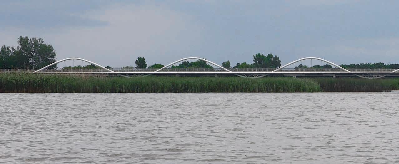
7. kép: A Tisza-tó vízfelülete Poroszló mellett az elkészült Eger-híddal / Picture 7 :
3
The water surface of Lake Tisza near Poroszló
The entire investment program includes a 42 km long path for bicycle traffic with four new bridges on the Po roszló – Tiszafüred F ishponds of Hortobágy route .
The investment No . K033 08 PST . of the NIF National Infrastructure Development Zrt ., in the construction of the main contractor of Hódút Kft , was based on the development of bicycle traffic between 2017–2020 or dered by the Lake Tisza Tourism Development Associ ation’s given project plans of the Permit design plans developed by TANDEM Mérnökiroda Kft . in the project that’s code was ÉAOP-2 .1 .1 / E-12-K1-2012-0009 on the topic of “Competitive tourism product and attraction development” and the project that’s code was ÉMOP2 .1 .1 / A-12-K1-2012-0008 on the topic of “Competitive tourism product and attraction development”. Permit design plans and construction plans were preceded by several study plans, which primarily examined the op timal buildability of the structures and the cycle path .
THE PURPOSE OF THE CONSTRUCTION
A NIF Nemzeti Infrastruktúra Fejlesztő Zrt. K033.08 PST. számú beruházásában, a Hódút Kft. Fővállalkozói kivitelezésében 2017–2020 között megvalósuló kerékpárforgalmi fejlesztés alapját a Tisza-Tavi Turizmus Fejlesztő Egyesület megbízásából a TANDEM Mérnökiroda Kft. által készített a „Versenyképes turisztikai termék- és attrakciófejlesztés” tárgyú ÉAOP-2.1.1/E12-K1-2012-0009 kódszámú projektben kidolgozott engedélyezési tervei és a „Versenyképes turisztikai termék- és attrakciófejlesztés” tárgyú ÉMOP-2.1.1/A12-K1-2012-0008 kódszámú projekt tervei adták. Az engedélyezési és kiviteli terveket több tanulmányterv előzte meg, melyek elsősorban a műtárgyak és a kerékpárút nyomvonal optimális megépíthetőségét vizsgálták. A teljes beruházási program a Poroszló Tiszafü red Hortobágyi halastavak útvonalon, mintegy 42 km hosszúságú kerékpárforgalmi nyomvonalat tartalmaz négy új híddal.
3 AZ ÉPÍTÉS CÉLJA Alapvető cél a biztonságos kerékpáros közlekedés feltételeinek megteremtése volt a 33. sz. főút mentén Poroszló és Tiszafüred között, csatlakoztatva a Tisza-tó körül már meglévő, üzemelő kerékpárforgalmi létesítményeket a nyugati és a keleti partok között. A megvalósítás után elvárt eredmény a 33. sz. főút kerékpáros-forgalomtól való mentesítése, ezáltal a forgalombiztonság növelése. A megépült létesítmény a térség turisztikai és hivatásforgalmi kerékpáros igényeit egyaránt szolgálja. IGÉNY, HELYSZÍN 2. Előzmények 3. A z építés célja

I.
ELŐZMÉNYEK
2
THE SECTION BETWEEN THE TISZA BRIDGE AND TISZAFÜRED
BRIDGE The first section of the facility belongs to the Northern Hungary Region and is located in Heves County .
The trail belongs to the Northern Great Plain Region and is located in Jász-Nagykun-Szolnok county . Con necting to the structure of the new cycling Tisza Bridge, the cycle path starts with a section supported by a re taining wall . The planned route, after the cycling Tisza Bridge follows the topographical design of the main road No . 33 . , similarly to the section before the river Tisza, with a nearly parallel line, as an independent two-way cycle path The end of the independent bicycle path is the industrial road next to the main road in the area of the 3 + 645 km section . This more than 300 m long mixed-use section, was built as an industrial road of the Central Tisza Region Water Directorate in a way, that it is also suitable for the periodic loads of maintenance vehicles and high axle load heavy-duty vehicles used for moving of logging material . The section is connected to the u-turn road for oversized vehicles (it is a parking lot, which also serves as a rest area, according to the daily traffic schedule). Following parallel the trail of the main road No. 33. (on the counter berm) we reach the border of Tiszafüred . Then, a little further away from the main road No . 33, we arrive on a short embank ment to the flood gate structure called flushing channel No . X ., which is bridged by a new, “Dutch type” opena ble bridge structure . After the structure, the cycle path reaches the area in front of the Tisza Balneum Thermal I DEMAND, LOCATION 4 The section between Poroszló and the Tisza bridge 5 . The section between the Tisza bridge and Tiszafüred
The cycle path starts in the administrative area of Po roszló, from the top of the flood protection embankment of the Eger creek, outside a populated area, as a contin uation of the asphalt-paved cycling route already es tablished on the flood defense embankment. Leaving the embankment on the south side of the main road No . 33 ., the first and also the one of the most impressive struc tures of the trail is the new bicycle bridge of the Eger creek . After that, the bike path continues almost parallel to the main road towards Tiszafüred . The topographical line drawing of the path uses the asphalt-paved road of the previous and already abandoned main road No . 33 ., which was available in a significant length at the south ern side of the existing embankment . The implemented two-way bicycle path between the Eger creek and the Szomorka creek was built using the existing abandoned road . And due to the watercourse crossings, new road way sections were built, that lead up to the bridges . From the Szomorka creek to the Kis-Tisza flood gate, the cycle path was also built on the abandoned pavement of the available old main road No . 33, with road recon struction. And from the Kis-Tisza flood gate, to the plant facility at the 32 + 520 km section area of the main road No . 33 ., an industrialroad was established, partly with a new track structure and partly with road reconstruc tion . In front of the building of the Fehér Amur Fisher man’s Tavern at the northern end of the Tisza Bridge, the cycling trail is slightly moving away from the road, leaving room for the double-sided retaining wall, that is built into the surface of the existing sloping . On the more than 4 .4 km long road, besides the two-way cycle path, two independent bridge structures were built, and a completely new drainage system has been implement ed between the slope of the main road and the planned cycle path . 5
16 4 THE SECTION BETWEEN POROSZLÓ AND THE TISZA
A létesítmény első szakasza területileg az Észak-Magyarországi Régióhoz tartozik és Heves megyében található. A kerékpárút Poroszló közigazgatási területén, az Eger-patak árvédelmi töltésének tetejéről, lakott területen kívül indul, folytatásaként az árvédelmi töltésen már korábban kialakított aszfaltburkolatú kerékpáros útvonalnak. A töltést a 33. sz. főút déli oldalán elhagyva a nyomvonal első és egyből egyik legimpozánsabb építménye az Eger-patak új kerékpároshídja. Ezt követően a kerékpárút a főúttal közel párhuzamosan halad tovább Tiszafüred felé. A helyszínrajzi vonalvezetés kihasználta a korábbi és már felhagyott 33. sz. főút aszfaltburkolatú útpályáját, mely a meglévő töltés déli oldali lábánál jelentős hosszban rendelkezésre állt. A kialakított kétirányú kerékpárút, az Eger-patakot és a Szomorka-patakot áthaladó kerékpároshidak között, a meglévő, felhagyott útpályát hasznosítva épült. A vízfolyás-keresztezések környezetében pedig új, a hidakra felvezető útpályaszakaszok készültek. A Szomorka-pataktól a Kis-Tiszazsilipig a szintén a rendelkezésre álló régi 33. sz. főút felhagyott burkolatán útpálya-rekonstrukcióval építették ki a kerékpárutat. A Kis-Tisza-zsiliptől a 33. sz. főút 32 + 520 kmsz. térségében lévő üzemi létesítményig pedig üzemi út létesült részben új pályaszerkezettel, részben pedig útpálya-rekonstrukcióval.
17 4 POROSZLÓ – TISZA-HÍD KÖZÖTTI SZAKASZ
5 TISZA-HÍD – TISZAFÜRED KÖZÖTTI SZAKASZ
közötti szakasz
A Tisza-híd északi hídfőjénél található Fehér Amur Halászcsárda épülete előtt a kerékpáros nyomvonal kissé eltávolodik a közút mellől, helyet hagyva a meglévő rézsű felületébe épített kétoldali támfalas megtámasztásnak. A több, mint 4,4 km hosszú nyomvonalon a kétirányú kerékpárút mellett két önálló hídműtárgy épült, valamint a főút ré zsűje és a tervezett kerékpárút között teljesen új vízel vezető rendszer valósult meg.
Az új kerékpáros Tisza-híd hídszerkezetéhez csatlako zóan a kerékpárút támfalas megtámasztású szakasszal indul. A tervezett nyomvonal a kerékpáros Tisza-híd után követi a 33. sz. főút helyszínrajzi kialakítását, hasonlóan a Tisza előtti szakaszhoz, közel párhuzamos vonalvezetéssel, önálló kétirányú kerékpárút jelleggel.
I. IGÉNY, HELYSZÍN 4.
A nyomvonal területileg az Észak-Alföldi Régióhoz tartozik és Jász-Nagykun-Szolnok megyében található.
szakasz 5.
A kerékpáros útvonal Tiszafüred belterületén belül több irányba válik szét, és több végponton ér véget a beavatkozás. Az északi irányba továbbhaladó nyom vonal a Balneum Thermal Hotel előtt keresztezi a Poroszló–Tisza-híd közötti Tisza-híd – Tiszafüred
Az önálló kerékpárút vége a főút mellett található üzemi út a 3 + 645 km-szelvény környezetében. Ez a több, mint 300 m hosszú, vegyes használatú szakasz a KözépTisza-vidéki Vízügyi Igazgatóság üzemi útjaként épült ki úgy, hogy az alkalmas a fenntartó járművek és a fakitermelés anyagkihordására használt, nagy tengelyterhelésű járművek időszakos teherviselésére is. A szakasz csatlakozik a túlméretes szerelvények visszafordítójáig (parkoló, mely a napi forgalmi rend szerint pihenőhely funkciókat is ellát). A 33. sz. főút nyomvonalával párhuzamosan (fióktöltésen) haladva érjük el Tiszafüred határát, majd a 33. sz. főúttól kissé eltávolodva, rövid töltésen érkezünk meg a ún. X. sz. öblítőcsatorna zsilipműtárgyához, melyet új, nyitható kivitelű, „Holland típusú” nyitható hídszerkezet hidal át. A műtárgy után a kerékpárút íves vonalvezetéssel éri el a Tisza Balneum Thermal Hotel előtti területét és ismét igazodik a 33. sz. főút nyomvonalához. Ez a szakasz szintén megerősített pályaszerkezettel épült, hogy a Közép-Tisza-vidéki Vízügyi Igazgatóság nagy tengelyterhelésű fenntartó járműveinek teherviselésére alkalmas legyen.
I
5 The
18 Hotel with a curved line and is once again aligned with the trail of the main road No . 33 . This section was also built with a strengthened track structure, to be able to take the load of the high axle load maintenance vehicles of the Central Tisza Region Water Directorate . The cy cling route is divided into several directions within the inner area of Tiszafüred, and the intervention ends at several endpoints The ongoing northbound trail cross es Main Road No . 33 . in front of the Balneum Thermal Hotel, then it crosses the Debrecen Füzesabony railway line No. 108, from where on the Tisza flood defense em bankment at Kakukk Street it joins the existing EURO Velo 11 trail that goes on the flood defense embankment. In the southern direction, passing the Balneum Ther mal Hotel, it joins the existing pavement of Kis-Tisza Street on a section of a flood protection embankment again . Then it leads along on the existing roadway to Ady Endre Street, where the cycle lane and connect ing cycle path realized in the previous investment are available . These sections are part of the EURO Velo 11 route network . The third direction crosses the Karcag – Tiszafüred railway line No . 103, separated from the flood protection industrial road., and on the modified Pankotay Jósa György Street it joins as an independent two-way cycle path to the bicycle route built next to the main road No 33 In the inner area of Tiszafüred, the implementation of the bicycle path and railway cross ing to be built on the route of Pankotay Jósa György Street connects the cyclable industrial road leading on the planned flood protection embankment and the main road No . 33 . In this area, the building and service facili ties of the Tiszafüred Bicycle Rental and Service Center are located, as one of the central infrastructural hubs of the bicycle paths around Lake Tisza . DEMAND, LOCATION section between the Tisza bridge and Tiszafüred 8. kép: Indulás Poroszlóról / Picture 8 .: Departure from Poroszló

II 1 CONCEPT
The studies and development ideas for the developmentof the bike path around the lake have been on the agenda continuously since the beginning of the 2000s. The growth of domestic cycling tourism has been expo nential in recent decades, however, road No. 33., that is crossing the lake meant a high accident risk. The engi neers of TANDEM Mérnökiroda Kft. and our company SPECIÁLTERV Kft. prepared their first studies in 2006. Our primary target was to create traffic safety, how ever, the use of economical and landscape-friendly en gineering solutions has also been identified as priority demands.Inthecase of the four major watercourse crossings of the route, we had to solve different technical problems with an economical approach. Considering the special ities of each site, we distinguished three different envi ronments:
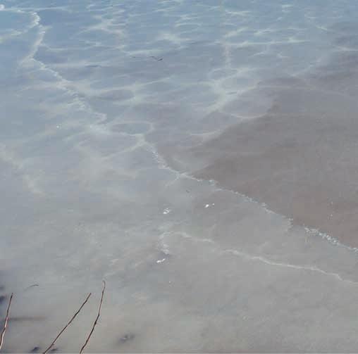
– The Eger- and Szomorka creeks formed the classic dammed lake environment. Shallow, with a small stream of water that can only be interpreted at low water levels, in the case of the Eger creek it is almost 300 m, and in the case of the Szomorka creek it is ap prox. 80 m of water surface.
SPECIÁLTERVPLANNINGKFT.
1. ábra: Gerendatartós verzió az Eger-patak esetében – Tanulmányterv 2006 / Figure 1.: Beam girder version in the case of the the Eger creek – Study plan 2006 II. KFT.

20
PLANNING – SPECIÁLTERV
1. Concept planning, studies
PLANNING, STUDIES
– In the case of the navigable main riverbed of the river Tisza, we were based on the possibilities of the load capacity reserves of the robust substructures of the existing road bridge.
– During the planning of the crossing of the flushing channel No. X. next to Tiszafüred, we had to consider that the average width of the channel is 80–100 m and as an additional water management need, we also had to solve the passage of the floating constructions per forming periodic riverbed maintenance. At each site, a different evolution led to the structures that were eventually built.
SPECIÁLTERVTERVEZÉSKFT.
tanulmányok II
1 TANULMÁNYOKKONCEPCIÓTERVEZÉS,
2. ábra: Rácsos tartós verzió az Eger-patak esetében – Tanulmányterv 2006 / Figure 2 : Truss-girder version in the case of the the Eger creek – Study plan 2006 II. TERVEZÉS – KFT. Koncepciótervezés,

SPECIÁLTERV
A Tisza-tavi kerékpárút fejlesztéséhez szükséges tanulmányok és fejlesztési elképzelések a 2000-es évek eleje óta folyamatosan napirenden voltak. A hazai kerékpáros turizmus térnyerése az utóbbi évtizedekben exponenciális volt, a tavat átszelő 33. sz. út azonban kiemelt baleseti kockázatot jelentett. A TANDEM Mérnökiroda Kft. és cégünk, a SPECIÁLTERV Kft. mérnökei 2006-ban készítették első tanulmányaikat. Elsődleges célunk a forgalombiztonság megteremtése volt, azonban kiemelt igényként határoztuk meg a gazdaságosság és a tájba illeszkedő mérnöki megoldások alkalmazását. A nyomvonal négy jelentősebb vízfolyás-keresztezése esetén eltérő műszaki problémákat kellett gazdaságos szemlélettel megoldanunk. Az egyes helyszínek sajátosságait figyelembe véve három eltérő környezetet különböztettünk meg: – Az Eger és Szomorka-patakok a klasszikus duzzasztott tó környezetet képeztek. Sekély, csak kis víz esetén értelmezhető vízfolyással, az Eger-patak esetében közel 300 m-es, a Szomorka-pataknál kb. 80 m-es vízfelülettel. – A Tisza folyó hajózható fő medre esetében a meglévő közúti híd robusztus alépítményeinek teherebírási tartalékaiban rejlő lehetőségekre alapoztunk. – Tiszafüred előtt a X. számú öblítőcsatorna keresztezésének tervezésénél a csatorna átlagos szélessége 80–100 m, és további vízügyi igényként az időszakonkénti mederkarbantartást végző úszóművek áthaladását is meg kellett oldanunk. Minden egyes helyszínen más evolúció vezetett a végül megépült műtárgyakig.
21
1.
The joint need of the client and the environmental conditions for the shape still existed, so we created an other alternative to highlight the symbol that fits into the landscape .
The bridge of the flushing channel No. X.: 97,87 m
In the first versions, the superstructures with small openings adapted to the widened substructures of the road bridge imitated two “wave” shapes: The main beams of the girder bridge with variable structural height plate-girders formed the soft waves, while the spiked torque-like shape of the truss main girders that follow the stress has resulted in an almost historiz ing form . The spiked waves imitated the rolling waves forming in stormy water . In the case of the wider main
22 The bridges of Eger and Szomorka creeks
At the structure of the flushing channel, the solu tion moved in a different direction . An agreement was reached with the Water Management Company on us ing their existing flood gate structures as bridges that were just a few 10 meters away to the south from the route, thereby achieving significant cost reductions. On the structure, the operational and cycling traffic needs were solved by applying a temporarily openable bridge .
II PLANNING – SPECIÁLTERV KFT 1 Concept planning, studies
The substructures of the road bridges built on Main Road No . 33 were prepared for a subsequent widening of the structure on their northern (rail side) sides. It might have seemed evident to use these existing substructure elements and building new facilities on them to solve the passage of cyclists economically . However, the bike path approaches the site from the south and also runs to the south side on the adjoining islands . Thus, in order to take advantage of the existing bridge substructures, we would have had to cross the road traffic of the Main Road No. 33. at least four times. For traffic safety reasons, this solution has been discarded and exploring the solutions of choosing the south side came to the fore .
The resulting bridge lengths were the followings: Eger creek bridge: 288,06 m Szomorka creek bridge: 83,84 m
In order to reduce the number of foundation difficul ties in the river bed, we increased the openings of the new bridge in a way, that in the case of the “lake” bridg es, a new substructure was added to every third support of the adjacent road bridge . Thus, the enlarged openings were bridged with a light steel structure, keeping the accordance with the repetitions of the adjacent struc tures .
Using the existing reinforced concrete structure, the length of the bridge to be built was reduced from the previous 97 m to only 6 m, which, even with the extra cost of the actuating machinery, resulted in significant savings .
In the original concept, the structure of the flushing channel would also have been built with this same sys tem onto or right next to the existing bridges of the road No . 33 .
.
girder, we have already examined the possibilities of bearing on separate substructures
On the south side, the first investor and designing joint intent was also calculating by widening the existing substructures, which would have meant 17 intermediate supports to be widened in the case of the Eger creek and 4 in the case of the Szomorka creek . Both the need for the bridges to fit into the land scape and the search for a formal symbol specific to the lake and its surroundings led the forming directions in the design of the structure . Out of several solutions developed, we finally chose the geometry of the wave, in which we saw the respect for the natural environ ment as a landscape and the adequacy of the supporting structure to be feasible without compromise .
23 Eger- és
A 33. sz. főút megépült közúti hídjainak alépítményei elő voltak készítve egy utólagos felszerkezet-szélesítésre az északi (vasút felőli) oldalon. Evidensnek tűnhetett ezen meglévő alépítményi elemek felhasználásával, azokra új felszerkezeket építve, gazdaságosan átvezetni a kerékpárosokat. A kerékpárút viszont délről közelíti meg a helyszínt és a csatlakozó szigeteken is a déli oldalon halad. Így a meglévő híd alépítmények lehetőségeinek kiaknázása esetén a 33. sz. út közúti forgalmát minimum négyszer kellett volna kereszteznünk.
A mederben való alapozási nehézségek darabszámának csökkentése érdekében megnöveltük az új híd nyílásait oly módon, hogy a „tavi” hidak esetében a szomszédos közúti híd minden harmadik támasza mellé került új alépítmény. Így a megnövelt nyílásokat egy könnyű acélszerkezettel hidaltuk át, tartva az összhangot a szomszédos szerkezetek ismétlődésében.
A szélesebb rácsos főtartó esetében pedig már vizsgáltuk a külön alépítményeken történő támaszkodás lehetőségeit is.
II. TERVEZÉS – SPECIÁLTERV KFT. 1. Koncepciótervezés, tanulmányok
Szomorka-patak-hidak
Az öblítőcsatorna műtárgyánál a megoldás más irányba mozdult el. A Vízüggyel megegyezés született a nyomvonaltól alig néhány 10 m-re délre lévő meglévő zsilipműtárgyuk hídként való a felhasználhatóságáról, ezzel jelentős költségcsökkentést elérve. A műtárgyon az üzemeltetési és kerékpáros forgalmi igényeket egy ideiglenesen nyitható híd alkalmazásával oldottuk meg. A meglévő vasbeton műtárgy felhasználásával a létesítendő híd hossza a korábbi 97 m-ről mindössze 6 m-re redukálódott, mely még a mozgató gépészet többletköltségével együtt is jelentős megtakarítást eredményezett.Amegbízói és környezeti adottságok együttes formai igénye továbbra is fennállt, így a tájba illeszkedő szimbólum kiemelésére egy újabb alternatívát készítettünk.
A déli oldalon az első közös beruházói és tervezői szándék szintén a meglévő alépítmények szélesítésével kalkulált, amely az Eger-patak esetében 17 darab és a Szomorka-pataknál pedig 4 darab közbenső támaszszélesítést jelentett volna. Párhuzamosan a hidak tájba illeszkedésének igénye és egy, a tóra és környezetére jellemző formai szimbólum keresése vezette a szerkezet tervezésének formai irányait. Számos kidolgozott megoldás közül végül a hullám geometriáját választottuk, melyben a természeti környezet tájképi tiszteletét és a tartószerkezeti megfelelőséget kompromisszum nélkül megvalósíthatónak láttuk. Az első verziókban még a közúti híd kiszélesített alépítményeihez igazodó kis nyílású felszerkezetek két „hullám” formát imitáltak: A gerendahíd változó szerkezeti magasságú gerinclemezes főtartói a lágy hullámokat formálták, míg a rácsos főtartók igénybevételkövető hegyes nyomatéki ábraszerű alakja már-már historizáló formát eredményeztek. A hegyes hullámok a viharos vízben kialakuló tarajos hullámokat imitálták.
Forgalombiztonsági okokból ezt a megoldást elvetették, és a déli oldalon vezetett megoldási lehetőségek vizsgálata került előtérbe.
Az Eger- és Szomorka-patakok esetében az 50 m fölé növelt támaszközök már új léptékben tették lehetővé számunkra a hullámmotívum kidolgozását. Egy folyamatos szinuszhullámot fejtettünk ki a támaszokra, mely a pálya alatt és felett haladva egy folytonos vonalat eredményezett. A kialakuló természetes vonal egyszer-
Eredeti koncepcióban az öblítőcsatorna műtárgya is ezen azonos szisztémával épült volna a meglévő 33. sz. úti hídra vagy közvetlenül mellé elhelyezve. Az így kialakuló hídhosszak az alábbiak voltak: Eger-patak hídja 288,06 m, Szomorka-patak hídja 83,84 m, X. sz. öblítőcsatorna hídja 97,87 m.
In order to ensure a rigid grip, we tried to connect the arches connected to the reinforced concrete support with a sufficiently rigid, but aesthetic grip. In the first versions, the arch was located asymmet rically towards the road bridge, then, as we continued to work on the planning, we switched to symmetrical designFinally,. we positioned the arches in the axis of the bridge, rigidly connected to the stiffener and passed through it, by a bond formed on top of the reinforced 10. kép: Nyitható hídszerkezet / Picture 10 .: Openable bridge structure 3. ábra: Eger- és Szomorka-patak-hidak – Támaszkoncepció vázlata / Figure 3 .: The bridges of Eger and Szomorka creeks – Support concept sketch

II . PLANNING – SPECIÁLTERV KFT . 1 . Concept planning, studies

In this range of openings, arch bridges are generally made with two main girders, which are typically stiffened or joined to each other by lateral bracings (“bas ket tab” arches) to give spatial rigidity to the structure. These extra shapes would have “divided the intended clear wave into new elements” so we decided to clamp a piece of torsionally rigid pipe section with sufficient diameter and clamp it in the rigid support .
24 In case of the Eger and Szomorka creeks, the increased distance between the supports to above 50 m already enabled us to develop the wave pattern at a new scale . A continuous sine wave was applied onto the supports, resulting in a continuous line passing below and above the track . The emerging natural line simultaneously imitated the soft waves of the lake and the basic shape of the waves of the vibrations that make up the universe . After finding the form, we adjusted its optimal stat ic boundary condition system to the selected shape . The structure was converted to a so-called “mixed track” bridge, that means it was designed for an upper deck bridge above the supports and for lower deck bridge in the span . We connected the track to the continuous curve with pressed grid bars in the upper deck bridge section, while pulled bars were drawn in the lower deck bridge section
re imitálta a tó lágy hullámait és a mindenséget alkotó rezgések hullámainak alapformáját. A forma megtalálása után annak optimális statikai peremfeltételei rendszerét hozzáhangoltuk a kiválasztott alakhoz. A szerkezetet ún. „vegyespályás”-sá alakí tottuk, vagyis a támaszok felett felsőpályás, míg mezőben alsópályás vezetésűre terveztük. A felsőpályás szakaszon nyomott rácsrudakkal, míg az alsópályás részen húzott függesztőrudakkal kapcsoltuk a pályát a folytatólagos ívhez.

II. TERVEZÉS – SPECIÁLTERV KFT.
tanulmányok
Ezen a nyílástartományon az ívhidak általános esetben két főtartóval készülnek, melyek jellemzően szélrácsokkal egymáshoz merevítve vagy egymáshoz csatlakozva („kosárfül” ívek) adnak térbeli merevséget a szerkezetnek. E többletformák a szándékolt tiszta hullámot „újabb elemekre bontották volna”, ezért egy darab kellő átmérőjű, csavarómerev csőszelvény ívtartó és annak a merev támaszba befogása mellett döntöttünk. A merev befogás érdekében a vasbeton támaszba bekötött íveket kellően merev, azonban mégis esztétikus megfogással igyekeztünk összekapcsolni. Az első ver ziókban az ív a közúti híd felé aszimmetrikusan helyezkedett el, majd a tervek tovább dolgozása során áttértünk a szimmetrikus kialakításra. Végül az íveket hídtengelybe pozicionáltuk, a merevítőtartóhoz mereven csatlakoztatva és azon átvezetve, a teljes szerkezet térbeli merevségét biztosító, a vasbeton pillérek tetején kialakított lekötésbe fogva. A pálya 12. kép: Eger- és Szomorka-patak-hidak – Kishajókikötő (nem valósult meg) / Picture 12 .: The bridges of Eger and Szomorka creeks – Small Boat Harbor (has not been implemented) 11. kép: Eger-patak-híd – Kivitelitervi látványterv / Picture 11 .: Eger creek bridge – Visual design study 1. Koncepciótervezés,

. We even suggested a small boat marina transfer point to be built on a floating pontoon that can be connected to the bridge, but was not built for acci dent prevention and operational reasons
.
The main road No. 33 crosses the river Tisza in the flow section at its 430 + 53 river km . Here, a road and a rail way Tisza bridge parallel to each other have been oper ating for decades .
.
II PLANNING – SPECIÁLTERV KFT 1 Concept planning, studies
In our first studies, above the riverbed we explored the possibilities of a new track plate expansion placed on the brackets of the superstructure of the road bridge’s truss structure .
5. ábra: A szélesített híd oldalnézete – Műszaki javaslat 2005 / Figure 5 : Side view of the widened bridge – technical proposal 2005 4. ábra: A tiszafüredi Tisza-híd felszerkezetének konzolos bővítése – Műszaki javaslat 2005 Figure 4 : Cantilever extension of the superstructure of the Tisza bridge in Tiszafüred – technical proposal 2005


The structure of the road and railway bridges in the two openings on the sides are two upper track girder bridges, while above the main riverbed they are trussell structures with low tracks . The railway bridges consist of three independent riveted beams with two supports, the road bridge is a three-hole, continuous truss girder made of welded sections with NF screw joints .
26 concrete pillars to ensure the spatial rigidity of the en tire structure . The stabilization of the track against tor sion was solved partly by the torsionally rigid box de sign of the cross-section and partly by the support of the 3D truss under the track . With the local widening of the roads on the bridg es, we also proposed and planned stopping places from where travellers can admire nature, which were liked by the Investors too and appeared on the implement ed structures
The widening of the Tisza Bridge in Tiszafüred
At the crossing of the main riverbed of river Tisza, we tried to ensure an economical cycle path passage using the existing Tisza bridge of the road
And in the openings os the sides, suiting with the de sign of the adjacent bridges, we developed sketch plans of an upper track structure . The proposed structure type was a steel 3D truss, resting on a cantilevered steel pier cap fixed to the existing reinforced concrete sub structures .
A Tiszafüredi Tisza-híd szélesítése A 33. sz. főút a Tisza folyót annak 430 + 53 fkm. folyá si szelvényében keresztezi. Itt egymással párhuzamo san egy közúti és egy vasúti Tisza-híd már évtizedek ótaAüzemel.közúti
27 elcsavarodás elleni stabilizálását részben a keresztmetszet csavarómerev szekrényes kialakításával, részben pedig a pálya alatti térrács alátámasztással oldottuk meg.A hidakon az útpálya lokális szélesítésével a természet megcsodálására kiálló helyeket is javasoltunk, beterveztünk, mely a Beruházók tetszését is elnyerve a megvalósuló szerkezeteken is megjelentek. Még egy úszó pontonon létesítendő kishajókikötő átszállóhelyhez hídról való csatlakozást is javasoltunk, de ez végül balesetvédelmi és üzemeltetési okokból nem valósult meg.
II. TERVEZÉS – SPECIÁLTERV KFT. 1. Koncepciótervezés, tanulmányok
Figure 6 : Proposed structure to the floodplain openings: 3D truss on the steel cantilever extension to be built on the substructure – technical proposal 2005

és a vasúti hidak szerkezete a két szélső nyílásban két-két felsőpályás gerendahíd, míg a főmeder felett egy-egy alsópályás rácsos szerkezet. A vasúti hidak három darab független kéttámaszú, szegecselt tartóból állnak, a közúti híd háromnyílású, folytatólagos rácsos tartó, hegesztett szelvényekből NF-csavaros illesztésekkel.ATiszafőmedrének keresztezésénél a meglévő közúti Tisza-híd felhasználásával igyekeztünk gazdaságos kerékpárút-átvezetést biztosítani. Az első vizsgálataink ban a medernyílásokban a közúti híd rácsos felszer kezethez történő konzolokra helyezett, új pályalemezbővítés lehetőségeit jártuk körül. A szélső nyílásokban pedig – igazodva a szomszéd hidak kialakításához – fel sőpályás szerkezet vázlatterveit dolgoztuk ki. A javasolt szerkezettípus egy acél térrács volt, a meglévő vasbeton alépítményekre rögzített, konzolos acél fejgerendán támaszkodva.Részletesebb vizsgálataink kimutatták, hogy a közúti hidat gazdaságosan tervezték. Karcsú szelvényei nem adtak kellő teherbírási tartalékot a külpontos kerékpá6. ábra : Az ártéri nyílásokra javasolt szerkezet: térrács az alépítményre építendő acélkonzol –bővítményenMűszakijavaslat 2005

Picture 13 .: Existing, operating Tisza bridges

II PLANNING – SPECIÁLTERV KFT 1 Concept planning, studies
The first opening, similar to the surrounding bridges, was designed as a upper deck bridge, while the interme diate openings are designed as lower deck bridges . With the curved outlined supporting elements, we were able to imitate the play of the waves of the “lake bridges”, thus allowing the appearance of the organic pattern of the cycling constructions established around the lake . Given the nautical gauge, the middle superstructure could not be “upside down,” so the wave in the middle is the transformed absolute value of the consistent func tion . 13. kép: Meglévő, üzemelő Tisza-hidak /
28 Our more detailed studies have shown that the road bridge was designed economically Its slender sections did not provide sufficient load capacity reserve to carry the cycling load fixed on it. We also examined the rein forceability of the structure, but the node designs also did not allow it in a cost-effective way . After all of these, we had to place the bike path on a new structure .
The new superstructure could be constructed as an independent bridge or by the extension of the existing substructures with a cantilever . The building of new pillars in the Tisza riverbed would have resulted in a very significant additional cost, so, the extension of the substructures was clearly the more economical solution, that must be examined . Geotechnical calculations showed significant load reserves on the caisson foun dations of riverbed pillars, thus, the technical task to be solved was to design the appropriate cantilever exten sionW.e examined several steel, concrete, reinforced concrete and prestressed concrete solutions for the exten sion and “stretching” of the pier cap . We came to that final result that we use a traditional reinforced concrete version, which wraps around the existing pier caps, connects the new cantilever pier cap extension to the existing one with sheared pins drilled through them and glued reinforced concrete spikes placed into them . With the designing of the supports for the widening, it was possible to establish a superstructure for bicycles with the same support distance as the parallel running adjacent bridges By this stage of the design, the “sine wave” concept of the Eger and Szomorka creek bridges has already been developed, so, we were looking for a structural system that was consistent with both of them and with the adjacent bridges .
A fejgerenda meghosszabbítására, „kinyújtására” több acél-, beton-, tartóbetétes beton és feszített beton meg oldást is vizsgáltunk. Végső eredményként egy hagyo mányos vasbeton verzióra jutottunk, mely a meglévő fejgerendákat körbeköpenyezve, azokon átfúrt nyírt csapokkal és befúrt–beragasztott vasbeton tüskékkel kapcsolja az új konzolos fejgerendabővítményt a meglévőhöz.Aszélesítés alátámasztásainak kidolgozásával lehe tőség nyílt egy a szomszédos, párhuzamosan futó hi dakkal azonos támaszközű kerékpáros felszerkezet létesítésére. A tervezés ezen fázisára az Eger- és Szomorka-patak-hidak „szinuszhullám” koncepciója már kialakult, így egy azokkal és a szomszédos hidakkal is összhangban lévő felszerkezeti rendszert kerestünk. Az első nyílást – a környező hidakhoz hasonlóan –felsőpályásra, míg a közbenső nyílásokat alsópályásra kialakítva, íves vonalvezetésű tartókkal imitálni tudtuk a „tavi hidak” hullámjátékát, ezzel végig megjelenhetett a tó környezetében létesített kerékpáros nagyműtár gyak organikus motívuma. Tekintettel a hajózási űrszelvényre, a középső felszerkezet nem lehetett „fejjel lefelé”, így a hullám középen transzformált abszolútértéke a következetes függvénynek. A végül kialakult hídforma a szélső nyílásban felsőpályás feszítőmű íves vonalvezetésű alsó övvel, 34,10 m-es támaszközökkel.
A közbenső nyílások 68,50 m támaszközű, alsópályás ívhidak, hálózatos függesztőrendszerrel. A függesztőrudak pozícióját hozzáigazítottuk a szomszédos közúti híd ferde rácsrúdjaihoz, így oldalról tekintve a hidakra, azok geometriájának ritmusa azonos, szerkezeti rendezettséget is sugall.

29 ros teher felvételére. A szerkezet megerősíthetőségét is vizsgáltuk, de a csomóponti kialakítások azt költség hatékony módon szintén nem tették lehetővé. Mind ezek után a kerékpárospályát új szerkezetre kellett he lyeznünk. Az új felszerkezetet független hídként vagy a meglévő alépítmények konzolos bővítésével lehetett elkészíteni. Új pillérek építése a Tisza medrében igen jelentős többletköltséggel járt volna, így egyértelműen az alépítmények bővítése volt a gazdaságosabb, kötelezően vizsgálandó megoldás. A geotechnikai számítások a mederpillérek keszonalapjaira komoly teherbírási tartalékokat mutattak ki, így a megoldandó műszaki fel adat a megfelelő konzolos kibővítés megtervezése volt.
II. TERVEZÉS – SPECIÁLTERV KFT. 1. Koncepciótervezés, tanulmányok
The finally formed bridge shape in the side opening is an upper deck bridge with tensioner with a curved line with a bottom belt, with 34 .10 m distance between the supports . The intermediate openings are lower deck arch bridges with 68 50 m distance between the sup ports, with a networked hanger system . We adjusted the positions of the suspension bars to the oblique bars of the adjacent road bridge, this way, when we look at the bridges from the side, the rhythm of their geometry is the same, that is also suggesting a structural order .

Figure 8 : Early,
II PLANNING – SPECIÁLTERV KFT 1 Concept planning, studies
308.ábra: A Tisza-híd színezett korai vázlatterve, még Vierendeel szélső nyílásokkal – Oldalnézet – hosszmetszet / colored Sketch Design of Tisza Bridge, still with Vierendeel side openings

31 7. ábra: A Tisza-híd szélesítésének elvi megoldása – Virtuális 3D „makett” / Figure 7 .: Conceptual solution of Tisza bridge widening, virtual 3D “model” II. TERVEZÉS – SPECIÁLTERV KFT. 1. Koncepciótervezés, tanulmányok


32 A Tisza-tavi hidak végleges formája / The final form of the bridges of Lake Tisza Szomorka-patak hídja / Szomorka creek: támaszok / Supports: 19,25 m + 47,40 m + 19,25 m hídhossz / Bridge length: 86,30 m acél felszerkezet tömege / Weight of steel superstructure: 112 t 9 ábra: Eger-patak hídja / Figure 9 .: Eger creek bridge 11. ábra: Szomorka-patak hídja / Figure 11 : Szomorka creek bridge 10. ábra: Tisza-híd / Figure 10 : Tisza bridge II PLANNING – SPECIÁLTERV KFT 1 Concept planning, studies
tanulmányok
33 Eger-patak hídja / Eger creek: Tisza-híd / Tisza bridge: támaszköz / Supports: 34,11 m + 3 × 68,50 m + 34,10 m hídhossz / Bridge length: 279,47 m acél felszerkezet tömege / Weight of steel superstructure: 362 t X. sz. öblítőcsatorna hídja / Flushing channel bridge: támaszköz / Supports: 6,30 m hídszélesség pályalemezen / Bridge width on the decking: 2,80 m acél felszerkezet tömege / Weight of steel superstructure: 9 t 12.: ábra: X. sz. öblítőcsatorna hídja / Figure 12 : Flushing channel bridge II. TERVEZÉS – SPECIÁLTERV KFT. 1. Koncepciótervezés, támaszok / Supports: 8,45 m + 50,72 m + 4×47,43 m + 50,72 m + 8,45 m hídhossz / Bridge length: 308,46 m acél felszerkezet tömege / Weight of steel superstructure: 383 t
According to the findings of the study plan, the cycle path was led over watercourses with bridge structures that are independent of road and rail bridges and were designed exclusively for cycling traffic. In determining the openings of the new bridges, we also took into account the width of the creekbed and reservoir, the relevant flood level, and the opening lay out of the adjacent road bridges . Due to the significant length of the trail on structures, the specific cost of the bike path is more expensive, so, a cost-effective solution has been formulated as a fun damental aspect during bridge designing . At the same time, we set the goal that the constructions to be built in the vicinity of the lake would not only correspond to the economic aspects, but also to be in harmony with 13. ábra: Eger-patak-híd – Oldalnézet és hosszmetszet / Figure 13 : The side view and longitudinal section of Eger creek bridge
The Eger creek is a natural internal watercourse of Lake Tisza, it is one of the elements of the flushing canal system No . IX . It only becomes an independent riverbed during the winter, at low water levels, therefore, it only presents itself as a watercourse in the traditional sense during the winter . In the case of the Szomorka creek (Bocskoros bridge), there is not even a riverbed-like ter
34 2 EGER AND SZOMORKA CREEK BRIDGES
Leaving Poroszló, the cycle path is running parallel to the main road No . 33 . and the Debrecen – Füzesabony railway line No . 108 . and crosses the open water section of the Poroszló basin of Lake Tisza . The existing infra structure led on the embankment, and over the internal watercourses called Szomorka and Eger creeks it cross es the reservoir on multi span bridges .
Authorization plans
After several study design phases The road construc tion authorization plans for the section of the cycle path between Poroszló and Tiszafüred from Poroszló to the northern abutment of the Tisza Bridge were pre pared by TANDEM Mérnökiroda Kft ., and the design of the structures was carried out in all design phases by Speciálterv Építőmérnöki Kft.
rain forming in the bridge opening . The environment of the “creek bridges” is a floodplain that is covered with water during most of the year . The bridge structures connect the related water surfaces of the reservoir to provide a transport linkage between the basins of Lake Tisza
.
II PLANNING – SPECIÁLTERV KFT 2 Eger and Szomorka creek bridges
Az új hidak nyílásainak meghatározásakor figyelembe vettük a patakmeder és a tározó szélességét, a mértékadó árvízszintet valamint a szomszédos közúti hidak nyílásbeosztását is. A jelentős hosszban műtárgyakon vezetett nyomvonal miatt a kerékpárút költségei fajlagosan drágábbak, így a költséghatékony megoldás a hídtervezés során alap vető szempontként fogalmazódott meg. Ugyanakkor célul tűztük ki, hogy a tó környezetében létesítendő mű tárgyak a gazdasági szempontokon túl megfeleljenek a különlegesen szép természeti környezetnek is. A műtárgyaknak tájba illeszkedőknek kellett lenniük, és akár a nemzeti park szimbólumaként is értelmezhető formai elemet hozva a környezetbe.
II. TERVEZÉS – SPECIÁLTERV KFT. 2. Eger- és Szomorka-patak-hidak
A kerékpárút nyomvonala Poroszlót elhagyva a 33. sz. főúttal és a 108. számú Debrecen Füzesabony vasútvonallal párhuzamosan haladva keresztezi a Tiszató Poroszlói-medencéjének nyíltvízi szakaszát. A meg lévő infrastruktúra töltésen vezetett, a Szomorka- és Eger-patak nevű belső vízfolyások fölött pedig többtámaszú hidak segítségével szeli át a tározót.
Az Eger-patak a Tisza-tó természetes belső vízfolyása, a IX. sz. öblítőcsatorna-rendszer egyik eleme. Csak a téli, kisvizes időszakban válik önálló mederré, ezért hagyományos értelemben vett vízfolyásként csak a tél idején mutatja meg magát. A Szomorka-patak (Bocskoros híd) esetében pedig még mederjellegű terepalakulat sincs a hídnyílásban. A „patakhidak” környezete mely az év nagy részében vízzel borított.
hullámtér,
35 2 EGER- ÉS PATAK-HIDAKSZOMORKA-
Több tanulmánytervi fázis után a Poroszló és Tisza füred közötti kerékpárút Poroszlótól a Tisza-híd északi hídfőjéig tartó szakaszának útépítési engedélyezési terveit a TANDEM Mérnökiroda Kft. készítette, a műtárgyak tervezését az összes tervfázisban a Speciálterv Építőmérnöki Kft. végezte.
A hídszerkezetek a tározó egymással összefüggő víz felületeit áthidalva biztosítanak közlekedési kapcsolatot a Tisza-tó medencéi között. Engedélyezési tervek A tanulmányterv megállapításai nyomán a kerékpárutat a vízfolyások felett a közúti és vasúti hidaktól függet len, kizárólag a kerékpáros-forgalom részére kialakított hídszerkezetekkel vezettük át.
The finalized structure of the Eger creek bridge is a lower deck and deck steel arch bridge with box crosssection bracing bracket with orthotropic deck plate having nine supports, with the following support distribution: 8 .45 m + 50 .72 m + 4 × 47 .43 m + 50 .72 m + 8 .45 m . The total length of the superstructure is 308 .46 m .
The structure of the Szomorka creek bridge is a lower deck bridge and deck steel arch bridge with box cross-section bracing bracket with orthotropic deck plate having four supports, with the following support distribution: 19 .25 m + 47 .40 m + 19 .25 m . The total length of the superstructure is 86 30 m .
Both bridges have a welded steel structure, the width of their box-supporting structures is 3 .91 m, and their structural height is 60 cm . By widening the track to 5 .81 m in the middle of the bridges, we also expanded 14. ábra: Szomorka-patak-híd – Oldalnézet és hosszmetszet / Figure 14 .: The side view and longitudinal section of Szomorka creek bridge
The load capacity of the bridges is 5 kN/m2 pedestrian and bicycle load according to the e-UT 07 .01 .11: 2011 Road Technical Specification. We run a 2 × 1.00 m wide bicycle lane along the bridges .
The two bridge structures were designed with the same type of superstructures and with substructures of similar geometry . However, due to the different support distributions – in addition to the number of inflection points – the shape of the arch supports is also slightly different of the two bridges .
II PLANNING – SPECIÁLTERV KFT 2 Eger and Szomorka creek bridges
36 the extraordinarily beautiful natural environment . The structures had to fit into the landscape and even bring a formal element that could be interpreted as symbols of the National Park . Continuous arcs, elaborated in accordance with the “wave” concept as it was presented in the study plan, form the main support structure on which the track is supported or hanged . The radius of the arcs are varied, they have a sine wave-like geometry At the supports, the arch holder falls under the bracing bracket, and at the fields, it arches over the bridge span, above the brac ing bracket . The height at the top points of the arches above the bracing bracket is 5 .81 m, and under the bracing bracket it is 2 30 m .
A vasbeton hídfő tömör szerkezetű, 3,91 m szélességű és változó vastagságú. A hídfőfallal egybeépülnek a 30 cm vastagú, függő vasbeton szárnyfalak. A felszerkezetet megtámasztó ingaoszlopok mögötti földtömeget a nyílás felé 30 cm vastag, a hídfőfallal egybebetonozott térdfal határolja.
37 A tanulmánytervben bemutatott „hullám”-koncepció nak megfelelően kidolgozott folytatólagos ívek alkotják a főtartó szerkezetet, melyre a pályát feltámasztottuk vagy függesztettük. Az ívek sugara változó, szinuszhullámhoz hasonló geometriájú. Támaszoknál az ívtartó a merevítőtartó alá bukik, mezőkben pedig a merevítőtartó fölött íveli át a hídnyílást. Az ívek tetőpontjának magassága a merevítőtartó felett 5,81 m, a merevtőtartó alatt pedig 2,30 m. Az Eger-patak-híd véglegesített szerkezete egy kilenctámaszú, 8,45 m + 50,72 m + 4 × 47,43 m + 50,72 m + 8,45 m támaszkiosztású ortotrop pályalemezes, alsó-, ill. felsőpályás acél ívhíd szekrény-keresztmetszetű merevítőtartóval. A felszerkezet teljes hossza 308,46 m. A Szomorka-patak hídja pedig egy négytámaszú, 19,25 m + 47,40 m + 19,25 m támaszkiosztású, ototrop pályalemezes, alsó- ill. felsőpályás acél ívhíd, szekrénykeresztmetszetű merevítőtartóval. A felszerkezet teljes hossza 86,30 m.
A hidak teherbírása az e-UT 07.01.11:2011 Útügyi műszaki előírás szerinti 5 kN/m2 nagyságú gyalogos és kerékpáros teher. A hidakon 2 × 1,00 m széles kerékpáros-forgalmi sávot vezetünk át. A két hídszerkezetet azonos típusú felszerkezettel, hasonló geometriájú alépítményekkel alakítottuk ki.
A közbenső pillérek alatt 3 darab Ø 100 cm átmérőjű fúrt cölöpből álló cölöpalapozást terveztünk. A cölöpök tengelytávolsága 3,00 m, a cölöpök hossza 13,00 m.
főket síkalapozással terveztük, a pillérek cölöpalapo zásúak.Ahíd tervezéséhez a vízügyi alapadatokat a vízfolyást kezelő Közép-Tisza-vidéki Vízügyi Igazgatóság (KÖTIVIZIG) egyeztettük. A hídépítési engedélyezési tervekre a Nemzeti Köz lekedés Hatóság Útügyi, Vasúti és Hajózási Hivatala 2013. augusztus 30-án szakhatósági állásfoglalásában hozzájárulást adott. Az engedélyezési tervekre a Heves Megyei Kormányhivatal Közlekedési Felügyelősége az út- és műtárgyépítési engedélyét 2013. október 8-án adta meg. Kiviteli tervek Az 1. és 2/A projektelemeket tartalmazó Poroszló-Tisza-híd északi hídfő közötti szakasz út- és vízépítési, forgalomtechnikai, híd- és műtárgykiviteli tervek készítését a Pannonway Építő Kft. nyerte és végezte el. A hídépítési szakági tervezési feladatokat a Speciálterv Építőmérnöki Kft. készítette. Alépítmények A hídfőket síkalapozással terveztük. A hídfőalaptestek 3,75 × 5,00 m alapterületűek, 40–80 cm között változó vastagsággal. Felső síkjuk 5%-os keresztesésű.
A cölöpösszefogó gerendák 8,00 × 1,40 × 1,40 m befoglaló méretűek, a pillér alatt szélességük 1,40 mII. TERVEZÉS – SPECIÁLTERV KFT. 2. Eger- és Szomorka-patak-hidak
A szekrény-keresztmetszetű merevítőtartók felső öve 1,95 m, alsó öve pedig 1,36 m széles, melyhez 0,98 m hosszúságú, változó keresztmetszetű, konzolos kereszt tartók kapcsolódnak. A vasbeton hídfők tömör falas szerkezetűek, merőleges, függő szárnyfalakkal. A híd
Az eltérő támaszkiosztások miatt azonban – az inflexiós pontok számán kívül – az ívtartók alakja is kismértékben különbözik a két híd esetében.
Mindkét híd hegesztett acélszerkezetű, szekrénytartós felszerkezetének szélessége 3,91 m, a szerkezeti magassága pedig 60 cm. A hidakat középen a pálya 5,81 m-re szélesítésével egy-egy pihenőhellyel is kibővítettük a tanulmánytervi koncepciónak megfelelően.
For the design of the bridge, the basic water manage ment data were agreed with the Central Tisza Region Water Directorate (KÖTIVIZIG), which manages the watercourse .
We designed the bridge abutments with flat foundation. The base bodies of the abutment have a floor area of 3 .75 × 5 00 m, with a thickness varying between 40–80 cm Their upper plane have 5% cross slope .
The Office of Roads, Railways and Shipping of the National Transport Authority gave its consent in a res olution to the bridge construction authorization plans on the 30th of August in 2013 . For the authorization plans, the Transport Inspectorate of the Heves County Government Office issued it’s road and structure con struction permission on the 8th of October in 2013 Construction plans Pannonway Építő Kft. won and carried out the prepa ration of the road and water construction, traffic engi neering, bridge and structure construction plans for the section between Poroszló and the northern abutment of the-Tisza bridge containing project elements 1 and 2/A .
The design tasks in the field of professional bridge con struction were prepared by Speciálterv Építőmérnöki Kft .
The 30 cm thick hanging reinforced concrete wing walls are integrated with the wall of the abutment .
38 them with a resting place according to the study plan concept .
Substructures
The reinforced concrete abutment is compact in structure, 3 .91 m wide and it’s thickness is varying .
The ground mass behind the pendulum columns supporting the superstructure is bounded towards the opening by a 30 cm thick knee wall that is concreted together with the abutment . Under the intermediate pillars, 3 pile foundations consisting of 100 cm diameter drilled piles were planned . The distance between the axes of the piles is 3 .00 m, the length of the piles is 13 .00 m . The enclosing size of the pile connecting beams is 8 .00 × 1 .40 × 1 .40 m, their width under the pillar increases from 1 .40 m to 3 .00 m . The size of the pile connecting beams is 8 .00 × 1 .40 × 1 .40 m at the supports marked 3–7 . The cross slope of the upper plane of the pile connectors is 5% . The pillars were formed clamped in the pile connecting beams . The pillars start from the upper plane of the pile connecting beam with an oval cross-sectional design . The cross section of the riverbed pillars of the bridg es grows upwards to a height of 3 .00 m . At the top of the pillars, 51 .5 cm thick structural beams with an oval layout were made to receive the arch holders . The ge ometric design of the pillars that are completely unique and slender looking from all directions was made with 3D modeling . The main axes of the lower and upper oval cross sections are perpendicular to each other . At the bottom of the pillars they are in the direction of the watercourse and at the top they are in the direction of the longitudinal axis of the bridge . The unique shapes of the vertical pillar reinforcement steels were constructed using the cross-sections taken from the spatial surface model .
The upper belt of the box cross-section bracing brack ets is 1 95 m and the lower belt is 1 .36 m wide, to which cantilever cross members with variable cross-sections of 0 .98 m length are connected . The reinforced concrete bridge abutments have a solid wall structure with perpendicular hanging wing walls . The bridge abutments were designed with a flat foundation, the pillars have piled foundation .
II PLANNING – SPECIÁLTERV KFT 2 Eger and Szomorka creek bridges
39 ről 3,00 m-re növekszik. A 3–7 jelű támaszoknál a cölöpösszefogó gerendák 8,00 × 1,40 × 1,40 m-esek. A cölöpösszefogók felső síkja 5%-os keresztesésű. A pilléreket a cölöpösszefogó gerendákba befogottan alakítottuk ki.
16. ábra: Pillér vasbeton terve / Figure 16 . Reinforced concrete plan of pillar II. TERVEZÉS – SPECIÁLTERV KFT. 2. Eger- és Szomorka-patak-hidak
15. ábra: A pillérek kontúrvasalásának térbeli modellje / Figure 15 : Spatial model of contour reinforcement of pillars


A pillérek a cölöpösszefogó gerenda felső síkjáról indulnak, ovális keresztmetszeti kialakítással. A hidak me derpilléreinek keresztmetszete felfelé haladva 3,00 m magasságig sudarasodik. A pillérek tetején az ívtar tók fogadására kialakított ovális alaprajzi kialakítású, 51,5 cm vastagságú szerkezeti gerendák készültek. A teljesen egyedi megjelenésű, minden irányból karcsú megjelenésű pillérek geometriai tervezése 3D modellezéssel készült. Az alsó és a felső ovális keresztmetszetek főtengelyei egymásra merőlegesek. A pillérek alján a vízfolyás irányában, felül pedig a híd hossztengelye irányában állnak. A függőleges pillérvasak egyedi alakjait a térbeli felület modelljén felvett keresztmetszetek segítségével szerkesztettük meg.

The structure of the Eger and Szomorka creek bridges are lower deck and deck steel arch bridge with box cross-section tie girder with orthotropic deck plate . Their structural height is 60 cm . The upper belt of the box cross-section tie girders is 1 .97 m and the lower belt is 1 .39 m wide . The deck plate is stiffened with longitudinal ribs with a cross-sectional size of 100 × 12 mm and a distance of 400 mm between them . The webs of the box holder are tilted 29° outwards from the vertical . With a length of 0 .98 m, cross members with cantilevers and variable cross-section (h = 60–31 cm) are connected to the web of the box girder, their distance from each other is 2 .95 m in the span, and next to the supports is 3 .05 m . The total width of the deck plate is 3 .91 m and it’s thickness is 12 mm . The cross slope of the deck plate is 3% in two directions, it has no longitudinal rise. In the intermediate span, in the middle of the field, the deck plate widens to 6 .31 m, with a curved layout .
Above the pillars, the pipe support is horizontal on a 3 .00 m long section and has a wall thickness of 40 mm .
The lower sections of the arch girder pillars that connect to the pillars were braced by concreting them up to the limit of the lower mounting unit . The concret17. ábra: Függesztőrudak / Figure 17 .: Suspension rods 18. ábra: Merevítőtartó keresztmetszete normál és szélesített szakaszon / Figure 18 .: The cross section of the tie girder on the normal and widened section
The radiuses of the main girder arches vary, changing its sign at several inflection points along the struc tural length of both bridges . The height of the apex of the arch measured from the deck level is 5 .81 m above the tie girderand 2 .31 m below the tie girder . The arch main holders are pipe sections with 610 cross-section and varying wall thickness .
40 Superstructures
For the sections between the pillars, 16 mm and 10 mm thick profile were used.
II . PLANNING – SPECIÁLTERV KFT . 2 Eger and Szomorka creek bridges
In the longitudinal section, bracing ribs were designed horizontally into the tube . The wall thickness of the pipe girder between the pillar and the abutment is 16 mm .

Az Eger- és Szomorka-hidak felszerkezete ortotrop pályalemezes, alsó- ill. felsőpályás acél ívhíd szekrény-keresztmetszetű merevítőtartóval. A szerkezeti magasság 60 cm. A szekrény-keresztmetszetű merevítőtartók felső öve 1,97 m, alsó öve pedig 1,39 m szélességű. A pálya lemez 100×12 mm keresztmetszeti méretű hosszbordákkal merevített, melyek távolsága 400 mm. A szekrénytartó gerincei a függőleges irányhoz képest 29°-kal kifelé döntöttek.
A középső támaszközben mezőközépen a pályalemez 6,31 m-re szélesedik, alaprajzilag íves kialakítással.
A merevítőtartó és a felette vezetett csőszelvény között sugarasan elhelyezett függesztőrudak találhatóak.
A függesztőrudak alsó csomópontjai a kereszttartók vonalába csatlakoznak. A hídfőtámaszoknál a reakciók felvételére a merevítőtartóban végkereszttartókat alakítottunk ki. A végkereszttartók magassága megegyezik a közbenső kereszttartókkal, lemezvastagságuk 16 mm.
41
A főtartó ívek sugara változó, mindkét híd szerkezeti hossza mentén több inflexiós pontban változtatja előjelét.Az ív tetőpontjának magassága a pályaszinttől mérve a merevítőtartó felett 5,81 m, a merevtő tartó alatt pedig 2,31 m. Az ívfőtartók Ø 610 keresztmetszetű cső szelvények, változó falvastagsággal. A pillérek felett a csőtartó 3,00 m-en vízszintes, falvastagsága 40 mm. A vízszintes szakaszon a csőben hosszirányú merevítőbordákat terveztünk. A pillér és hídfő között a csőtartó falvastagsága 16 mm. A pillérek közötti szakaszokon 16 mm-es és 10 mm-es falvastagságú szelvényeket alkalmaztunk.Azívtartó pillérekhez kapcsolódó alsó szakaszait az alsó szerelési egység határáig kibetonozással merevítettük. A betonozó–levegőztető nyílásokat az acélszerkezet gyártmányterveinek készítésekor alakítottuk ki. A merevítőtartó és az alatta vezetett csőtartó között Ø 193,7×20 mm csőszelvényű rácsozás biztosítja a me revítőtartó alátámasztását. A rácsrudak a merevítőtartó gerincvonalába kötnek be. A rácsrudak alsó végeiken közvetlenül az ívtartó palástjához csatlakoznak, az ívtartó belsejében a csomópontotokat körbemenő keresztirányú bordával merevítettük.
A felszerkezet és az alépítmény kapcsolatának megtervezésekor egyedi megoldások alkalmazására volt szükség. A hosszú, helyszínrajzilag egyenes, csőtartókon támaszkodó szerkezeteken a megtámasztásoknak nyomatékbíró merev befogást kellett biztosítanunk a 19. ábra: Felsőpályás szakasz keresztmetszete / Figure 19 : The cross section of the upper deck bridge section
A hídfőknél a felszerkezet vízszintes keresztirányú elmozdulását acélszerelvényekkel akadályoztuk meg. Statika
Felszerkezetek
A szekrénytartó gerincéhez 0,98 m hosszú változó keresztmetszetű (h = 60 31cm) konzolos kereszttartók kapcsolódnak, távolságuk mezőben 2,95 m, a támaszok mellett pedig 3,05 m. A pályalemez tejes szélessége 3,91 m, lemezvastagsága 12 mm. A pályalemez 3%-os kétirányú keresztesésű, hosszirányú emelkedése nincs.
II. TERVEZÉS – SPECIÁLTERV KFT. 2. Eger- és Szomorka-patak-hidak
A függesztőrudak keresztmetszete az igénybevételekhez igazodva Ø 24–42 között változó.
The bridge, which is braced with a continuous mul ti-support, waving arch, is rigidly supported at the in termediate supports and articulated at the abutments . Due to the rigid intermediate grips, the superstructure and the single-row pile substructures are forming a continuous frame bridge and the intermediate sup ports absorb torque at the “T” branches of the frames . Due to the weak subsoil, at the intermediate supports 3 piles per each support were required . The piles were arranged in a row, as this reduced the lower clamping rigidity of the “frame columns”, thereby reducing the ef fects of tensing in the rigid structure
As the structure is clamped in the subsoil with the piles and the clamping rigidity of the soil has an effect on the stresses of the superstructure, we examined the embedding rigidity of the piles over a wider range, in several different cases . The piles were modeled by lim-
There are suspension rods placed radially between the tie girder and the pipe section guided above it .
The lower nodes of the suspension rods join into the line of the cross girders .
The superstructure support of the Eger bridge is fixed on the middle 3 pillars, on the 2 outer pillars on each side, the longitudinal displacement is ensured by a layer of Teflon placed in the tie down assembly. The super structure supports of the Szomorka Bridge are fixed on both intermediate pillars . The thermal movements de velop evenly towards the two abutments in case of both structures .
A grid on the pipe section provides support for the tie girder with a diameter of 193 .7 × 20 mm between the tie girder and the pipe support underneath it . The grid bars connect to the ridge line of the tie girder . The members of the truss are connected at their lower ends directly to the curved surface area of the arch support, inside the arch support, the nodes are stiffened with a surround ing transverse rib .
At the abutment supports, end cross girders were formed in the tie girder to take the reactions .
The height of the end cross girders is the same as the in termediate cross girders, their plate thickness is 16 mm .
At each of the abutments, the vertical support is pro vided by 2 pendulum columns . The pendulum columns allow longitudinal movement of the bridge due to ther mal expansion, and they transmit the vertical force to the abutment . The transverse movement of the bridge ends are prevented by shearing pins attached to the knee walls of the abutments – by a tube-in-tube system, without obstructing the thermal expansion movements .
At the abutments, the horizontal, transverse movement of the structure was prevented by steel fittings. Statics When designing the connection between the super structure and the substructure, it was necessary to ap ply custom solutions . On the long, marked on the site plan as straight structures, supported on pipe girders, the supports had to provide a torque-resistant rigid grip in all directions of the space (Mx, My, Mz), there fore, we could not apply the classic bearing structures and bearing arrangement solutions .
The geometry of the pillars follow not only aesthetic aspects but also static aspects . The goal was a design that follows the stress, through which the rigidness of the pillar was gradually reduced as we moved towards the pile clamper .
The cross section of the suspension rods varies from Ø 24 to Ø 42, depending on the loads .
42 ing-aeration openings were formed during the making of the production plans of the steel structure .
II PLANNING – SPECIÁLTERV KFT 2 Eger and Szomorka creek bridges
The arch girders are supported on the pillars by a longitudinal and transverse torque-resistant connec tion. The stiffened tie down assembly provides fixed support with studs concreted into the pillar heads .
.
Tisza-tó
Munka: - Szomorka-patak feletti Tervező: Dési Attila 1.oldal2020. 05. 14.Modell: Szomorka_Modell 15b_INGA felso CSP -
II. TERVEZÉS – SPECIÁLTERV KFT. 2. Eger-
Az Eger-patak esetében a közbenső 3 pilléren lévő fix megfogás a fentiek alapján végzett eredmények alapján megfelelőnek bizonyult.
alátámasztása a pilléreken hossz- és keresztirányban nyomatékbíró kapcsolattal történik.
A pillérek geometriája az esztétikai szempontok mellett statikai szempontokat is követ. Cél volt az igénybevétel-követő kialakítás, mely révén a cölöpösz szefogó felé haladva a pillér merevségét fokozatosan csökkentettük. Mivel a szerkezet a cölöpökkel az altalajba befogott, és a talaj befogási merevsége visszahat a felszerkezet igénybevételeire, a cölöpök ágyazási merevségét szélesebb tartományban, több esetre is vizsgáltuk. A cölöpöket határrugós ágyazással modelleztük.
20. ábra: Csőtartó egy irányban mozgó lekötése – Végeselemes modell / Figure 20 : The finite element model of the tie down of the unidirectionally moving pipe girder 21. ábra: Végkereszttartó és ingaoszlopos támaszok – Végeselemes modell / Figure 21 : The finite element model of end cross girder and pendulum column supports
43 tér minden irányában (Mx, My, Mz), ezért a klasszikus saruszerkezeteket, saruelrendezési megoldásokat nem alkalmazhattuk.Azívtartók
és Szomorka-patak-hidak
A merevített lekötő szerelvény fix megtámasztást biztosít a pillérfejekbe bebetonozott tőcsavarokkal.
Az Eger-híd felszerkezete a középső 3 pilléren fix megtámasztású, a szélső 2–2 pilléren a hosszirányú elmozdulás a lekötő szerelvénybe helyezett teflonréteggel biztosított. A Szomorka-híd felszerkezete mindkét közbenső pilléren fix megtámasztású. A hőmozgások mindkét műtárgy esetében a két hídfő felé egyenletesen alakulnak ki.
A hídfőknél a függőleges megtámasztást 2–2 ingaoszlop biztosítja. Az ingaoszlopok a híd hőtágulásból adódó hosszirányú mozgását engedik, a függőleges erőt pedig közvetítik a hídfőre. A hídvégek keresztirányú elmozdulását a hídfőtérdfalakra rögzített nyírótüskék gátolják meg – cső a csőben rendszerrel, a dilatációs mozgások akadályozása nélkül. A folytatólagos többtámaszú, hullámzó ívvel merevített híd a közbenső támaszoknál mereven, a hídfőknél csuklósan megtámasztott. A merev közbenső megfogások miatt a felszerkezet és az egysoros cölöpös alépítmények egy folytatólagos kerethidat alkotnak, a közbenső támaszok nyomatékot vesznek fel a keretek „T” elágazásainál. A közbenső támaszoknál a gyenge altalaj miatt 3–3 cölöpre volt szükség támaszonként. A cölöpöket egy sorba rendeztük, mivel így a „keretoszlopok” alsó befogási merevsége csökkenthető volt, csökkentve a merev szerkezet befeszüléséből keletkező hatásokat.
kerékpáros híd
ferde_ V2 másolata.axs
AxisVM X5 R3g Jogosult felhasználó: Dési Attila okl. építőmérnök Munka: Tisza-tó - Szomorka-patak feletti kerékpáros híd Tervező: Dési Attila 1.oldal2020. 05. 14.Modell: Szomorka_Modell 15b _AxisVM_r1__5__UJRAFUTTAT_torolni másolata.axs 23.ábra: Övlemezzel merevített kereszttartók végeselemes modellje a kiszélesedő pályalemezél / Figure 23 : Finite element model of cross girders stiffened with flanges at the widening deck plate 24. ábra: Merevítőtartó és ívtartó kapcsolata / Figure 24 : Tie and arc girder connection 22. ábra: Eger-patak-híd – Végeselemes modell / Picture 22 : Finite element model – Eger creek bridge
44 The rod connections are slightly eccentric with respect to the arc girder axis, thus, the forces of the structure became more favorable for torsion . At the more used grid bar connections, internal stiffening ribs were placed in the curved main support tube .
The webs of the cross girders are without a flange at the bottom, which is why the compliance of the cross girders to dent stability loss were examined in detail . Only in the case of widened crossbars at the resting places, the cross girders had to be fitted with flanges and only on a short section .
Mainly to improve the dynamic behavior of the bridge structure, the sections of the arches under the tie gird ers were designed with concrete filling.

AxisVM X5 R3g · Jogosult felhasználó: Dési Attila okl. építőmérnök Munka: Tisza-tó - Eger-patak feletti kerékpáros híd Tervező: Dési Attila 1.oldal2020. 05. 14.Modell: Eger_Modell 20b__EC__03__Beilleszt_09e__belso_bordaval4__190702_UJRAFUTTAT_SURIT__BORDA KIVAGAS2.axs
II PLANNING – SPECIÁLTERV KFT 2 Eger and Szomorka creek bridges
45 25. Rudakábra:feszítése a merevtőtartó megemelésével / Figure 25 Tensioning: the hangers by raising the tie girders 26. Szomorka-patak-hídábra:–Végeselemesmodell / Figure 26 : The finite element model of Szomorka creek bridge II. TERVEZÉS – SPECIÁLTERV KFT. 2. Eger- és Szomorka-patak-hidak


46 The rods hanging the tie girder to the arches are ar ranged radially, their diameter increase continuously from the shoulder of the arch inwards, according to the stresses .
The suspension bars were tightened as part of the construction technology . In such a way that, after weld ing the tie girder and the arch girder ready, the tie gird er had to be raised by 15 mm in the middle of the field with the specified pressing force, so that, after elimi nating the reactions of the temporary support and the added pressing force, the appropriate tensile (pulling) force can awaken in the rods . With this, it was possible to avoid stretching the bars one by one, which was a great ease during the construction . Dynamics The specialityof the Eger and Szomorka bridges is that they are braced by only one arch Although the tie gird er is a torsionally rigid box in it’s cross-section, but at the same time, the bridges are clamped only at the points above the pillars with a pipe cross-section that has large wall thickness . During the construcion plan ning, after detecting the adequacy to the load capacity 14. kép: Eger patak – Dinamikus terhelés / Picture 14 :Eger creek – Dynamic load test
II PLANNING – SPECIÁLTERV KFT 2 Eger and Szomorka creek bridges

47 lyeknél kiszélesedő kereszttartóknál kellett a kereszttartókat és csak rövid szakaszon övlemezekkel ellátni.
A merevítőtartót az ívekhez függesztő rudak radiális elrendezésűek, átmérőjük az ívváltól befelé haladva folyamatosan növekszik, az igénybevételeknek megfelelően.Afüggesztőrudakat az építéstechnológia részeként feszítettük meg oly módon, hogy a merevítőtartó és az ívtartó készre hegesztését követően a megadott sajtóerővel meg kellett emelni a merevítőtartót a mezőközépen 15 mm-rel, hogy utána a járomreakciókat és hozzáadott sajtolási erőt megszüntetve, a rudakban a megfelelő feszítő- (húzó)erő ébredjen. Ezáltal a rudak egyesével való feszítése elkerülhető volt, amely nagy könnyebbséget jelentett a kivitelezés során.
II. TERVEZÉS – SPECIÁLTERV KFT. 2. Eger- és Szomorka-patak-hidak
Főként a hídszerkezet dinamikai viselkedésének javítása érdekében az ívek merevítőtartó alatti szakaszait kibetonozással terveztük.
Dinamika Az Eger- és Szomorka-hidak sajátossága, hogy mindösszesen egy ívvel merevítettek. Bár a merevítőtartó csavarómerev szekrény keresztmetszetű, ugyanakkor a hidak csak a pillérek feletti pontokban vannak befogva egy nagy falvastagságű csőkeresztmetszettel. A kiviteli tervezés során, teherbírási (szilárdsági, stabilitási) és a használhatósági (hasznos terhekből keletkező alakváltozás) megfelelések kimutatását követően elvégeztük a hídszerkezet dinamikus terhelésekre való vizsgálatát is. A dinamikus terhelésekre kapott szerkezeti válaszokból kimutatható volt, hogy a felszerkezet csaravási merevségének növelése volt szükséges, mivel a kitűzött komfortfokozathoz tartozó gyorsulási kritériumokat a szerkezet első körben még nem teljesítette. A komfortérzettel kapcsolatos kritériumokat általában akkor szükséges igazolni, ha a felszerkezet alaprezgésszáma kisebb, mint 5,00 Hz függőleges rezgések esetén, 2,50 Hz vízszintes síkú (keresztirányú) és csavarási regések esetén. A két híd több sajátrezgésalakja is a gyalogosdinamikailag érzékeny tartományba esett. A hidak alapvetően kerékpáros funkció kiszolgálására épültek, és a kerékpáros nem okoz olyan jellegű dinamikus hatást, mint egy hídon áthaladó gyalogos, ugyanakkor fontos volt a hidak dinamikai megfelelőségének, komfortérzetének javítása. A dinamikai csökkentés érdekében a következő eszközökkel éltünk: – dinamikus terhelés számításakor a támaszrugók merevségét növeltük – a nemzetközi szakirodalmi ajánlásoknak megfelelően, – a korábban alkalmazott Ø 100 × 20-as rácsrudak keresztmetszetét Ø 193,7 × 20 szelvényre növeltük, – az alsó ívszakaszokat részben kibetonoztuk, amellyel a merevséget növeltük, és az alkalmazott beton által javult a szerkezet csillapítása is.
15. kép: Kibetonozott csőtartó és növelt keresztmetszetű rácsrudak / Picture 15 .: Filled main pipe and lattice with increased cross sections

The frequencies calculated in this way and their associ ated vibrational shapes are as follows (Table 2.). During the dynamic calculations, we assumed low pedestrian traffic on the bridge. In the classification ac cording to pedestrian dynamics recommendations: „A pedestrian bridge of average use, occasionally crossed by a larger group of pedestrians”.
II PLANNING – SPECIÁLTERV KFT 2 Eger and Szomorka creek bridges
48 (strength, stability) and usability (deformation due to payloads), we also examined the bridge structure for dynamic loads . The structural responses to the dynamic loads showed that it was necessary to increase the tor sional rigidity of the superstructure, because the accel eration criteria belonging to the set comfort level have not yet been met by the structure in the first round. The comfort criteria usually need to be verified if the basic vibration number of the structure is less than 5 .00 Hz in case of vertical vibrations and 2 .50 Hz for horizontal (transverse) and torsional vibrations. Sever al natural frquency shapes of the two bridges also fell into the dynamially sensitive range of the pedestrians . The bridges are basically built to serve a cycling func tion, and the cyclist does not cause the kind of dynam ic effect that a pedestrian crossing a bridge, but at the same time, it was important to improve the dynamic adequacy and comfort of the bridges .
The frequencies calculated in this way and their associ ated vibrational shapes are as follows (Table 1.).
The changes, due to the modifications at the bridge of the Szomorka creek are: – the frequency of the 1st torsional vibration increased from 1 .91 Hz to 2 .43 Hz, – the frequency of the 1st longitudinal vibration in creased from 2 .53 Hz to 3 .63 Hz, – the frequency of the 1st bending vibration increased from 4 .80 Hz to 5 .72 Hz .
As a result of the listed modifications, the following changes occurred at the bridge of the Eger creek: – the frequency of the 1st torsional vibration increased from 1 .61 Hz to 2 .41 Hz, – the frequency of the 1st longitudinal vibration in creased from 1 .47 Hz to 1 .95 Hz, – the frequency of bending vibration 1 increased from 2 .54 Hz to 2 .74 Hz .
To reduce dynamic sensitivity, we used the following –tools:during calculations of the dynamic load, the rate of the support springs was increased – in accordance with the recommendations of the international literature, – the cross-section of the previously used Ø 100 × 20 grid bars was increased to Ø 193 .7 × 20 sections, – the lower arch sections were partially filled with con crete, which increased the rigidity and also improved the mitigation of the structure by the concrete used .
27.: ábra: Eger-patak – 1. hajlítórezgés / Figure 27 . Eger creek – 1st vertical bending vibration
frekvenciák és a hozzájuk tartozó rezgésalakok a következőek: A módosítások, változtatások hatására a Szomorka-patak hídjánál: – az 1. csavarórezgés frekvenciája 1,91 Hz-ről 2,43 Hz-re, – az 1. hosszirányú rezgés frekvenciája 2,53 Hz-ről 3,63 Hz-re, – az 1. hajlítórezgés frekvenciája 4,80 Hz-ről 5,72 Hz-re
1 táblázat: Eger-patak
/
49 A felsorolt módosítások hatására az Eger-patak hídjá–nálaz 1. csavarórezgés frekvenciája 1,61 Hz-ről 2,41 Hz-re, – az 1. hosszirányú rezgés frekvenciája 1,47 Hz-ről 1,95 Hz-re, – az 1. hajlítórezgés frekvenciája 2,54 Hz-ről 2,74 Hz-re
frekvenciák és a hozzájuk tartozó rezgésalakok a következőek: A dinamikai számítások során a hídon gyér gyalogosforgalmat feltételeztünk. A gyalogosdinamikai ajánlások szerinti besorolásban: „Átlagos használatú gyalogos híd, amelyen alkalmanként nagyobb gyalogos csoport halad át”. Csavarórezgés / Torsional 2.742.784.674.915.294.474.702.412.412.502.582.632.701.2.3.4.5.6.vibrationHosszirányúrezgés/Longitudinalvibration1.1.95Hajlítórezgés/Bendingvibration1.2.3.4.5.6.7. hídja Table :
Aznövekedett.ígyszámított
Aznövekedett.ígyszámított
1
Eger creek bridge LongitudinalHosszirányúrezgés/vibration Csavarórezgés / Torsional vibration Hajlítórezgés/Bendingvibration 1. 1. 2. 3. 1. 2. 3,63 2,43 3,86 5,57 5,72 6,48 2 táblázat: Szomorka-patak hídja / Table 2 : Szomorka creek bridge II. TERVEZÉS – SPECIÁLTERV KFT. 2. Eger- és Szomorka-patak-hidak
– side wiev II PLANNING – SPECIÁLTERV KFT 3 Tisza bridge
The possibility of crossing between Poroszló and Tiszafüred on the road has been available in the area since 1891 . A road-rail bridge over the River Tisza en sured the passage . The two riverbed piers of the roadrail bridge were blown up in 1919, and then the structure was restored after the World War. In 1937, a traffic restriction had to be introduced on the road-rail bridge due to it’s insufficient load capacity. At that time, the construction of a new railway bridge was planned, to gether with the construction of a road bridge on the outflowing side, parallelly, having the same distribution of supports . The substructures of the road bridge were prepared in 1941/42 . However, due to the events of the war, it was no longer possible to place the su perstructure The existing pillars were not blown up during the war, however, they suffered minor damages . The planning of the final road crossing began in 1962. The designer was UVATERV (Pál Kékedy). The completed bridge was realized with welded steel trusses above the channel openings and box girder composite structure above the floodplain openings. No significant changes have been made to the sub structures of the bridge since the handover . The I .–III . pillars are standing on a caisson fondation. The floor plan size of the caisson is ~5 5 × 11 0 m . The pillars were made with a 1:20 ratio . With natural stone cover on their outer surface. The filling material is unreinforced concrete structure throughout the whole structure . The depths of the caissons are respectively 21 .23 m, 22 .53 m and 21 .85 m . The pillar marked IV . is with wooden pile foundation . The height of the pile cap is 1 .80 m . The entire masonry is made of floating concrete. Tisza-híd – Általános terv – oldalnézet Figure 28 .: Tisza-bridge General plan
/
–
28. ábra:
50 3 TISZA BRIDGE 3.1. The trussexisting,composite bridge
II. TERVEZÉS – SPECIÁLTERV
3 TISZA-HÍD 3.1. Meglévő,
A meglévő pilléreket a háború során nem robbantották fel, azonban kismértékű károsodások érték őket.
A pillérek 1:20 hajlással készültek, külső felületükön terméskő burkolattal ellátva. A kitöltő anyag a teljes szerkezetben vasalatlan betonszerkezet. A keszon mélysége rendre 21,23 m, 22,53 m és 21,85 m. A IV. jelű pillér facölöpös alapozású. A cölöpösszefogó magassága 1,80 m. A teljes falazat úsztatott betonból készült. KFT. 3. Tisza-híd
A tervező az UVATERV (Kékedy Pál) volt. A kivitelezett híd hegesztett rácsos acélszerkezetű medernyílásokkal és szekrényes öszvérszerkezetű ártéri nyílásokkal valósult meg. A híd alépítményeit érintő jelentős változtatás az átadás óta nem történt. Az I.–III. jelű pillérek keszon alapon állnak. A keszon alaprajzi mérete ~5,5 × 11,0 m.
51 rácsos öszvérhíd
A végleges közúti átkelő tervezése 1962-ben kezdődött.
A Poroszló és Tiszafüred közötti közúti átkelés lehetősége 1891 óta adott volt a térségben. A Tiszán közúti-vasúti híd biztosította az átjutást. A közúti-vasúti híd két mederpillérét 1919-ben felrobbantották, majd a világháborút követően a szerkezetet helyreállították. 1937ben a közúti-vasúti hídon az elégtelen teherbírás miatt forgalomkorlátozást kellett bevezetni. Ekkor új vasúti híd építését vették tervbe, a kifolyási oldalon vele párhuzamosan, azonos támaszkiosztással közúti átkelő építésével együtt. A közúti átkelő alépítményeit 1941/42ben készítették el. Azonban a háborús cselekmények miatt a felszerkezet elhelyezésére már nem volt mód.
During the construction, the missing parts of the ex isting pillar masonry were also grouted, as well as tak ing core samples for checking the homogeneity of the pillar body behind the stone masonry . The core samples
According to the construction plans, the surface of the pier caps had to be engraved back to a minimum length of 10 cm on each side, and after cleaning and pas sivation, the reinforcing bars became usable and bound into the new concrete . After this, the entire pier cap had to be sheathed with a monolithic reinforced con crete structure with drilled and glued pins and towards the planned bicycle bridge, the reinforced concrete pier cap reinforcement had to be extended cantilevered . We originally designed a rigid steel insert for the elongat ed, cantilevered pier cap, which would have been con nected to the old structure with connecting studs and in addition to their final load capacity, the temporary scaffolding and formwork could also have been hung on them . The professional contractor eventually used scuf foldings attached to the pillar body, making the rigid support inserts optional .
The superstructural system of the new bicycle bridge is a two support upper deck bridge in the side fields, and in the three fields in the middle,it is a series of two support lower deck bridges with steel arches . When choosing the designed slender arch bridge structure, the main aspect was to keep the superstructure’s weight as light as possible, to minimize the load on the new reinforced concrete cantilever . The hangers of the arch support were formed in such a network system, which follows the grid bar allocation of the truss bars of the truss system of the existing road bridge . The advantage of network arch bridges is that the loads absorbed from the tie girder through the bars are more evenly received by the arch structure due to the mesh design of inter secting hanging elements than in the case of the more conventional arch bridges hanged vertically or radially . This design is especially advantageous for bridges that have a significant live load/dead load ratio in case of high concentrated loads, such as railway bridges and pedestrian bridges .
52 3.2.
The planned cycling Tisza Bridge rests on reinforced concrete cantilevers using the stone covered concrete pillars of the existing road bridge . And as the outer most supports of the new bridge, new reinforced con crete abutments are made next to the abutments of the road bridge . With the 50–50 cm widening of the pier caps of the existing bridge pillars and by wrapping them around and cantilevering the new reinforced concrete pier cap extensions .
The new structure was fixed to the old pier caps with drilled, glued reinforcing bars and by stretching the new reinforced concrete covering onto the surface of the old pier caps .
Using an existing structure as intermediate supports At the bicycle bridge, the lateral widenings of the pier caps were also examined, taking into account both steel and reinforced concrete cantilever The expert opinion prepared for the construction plan focused especially on the condition of the existing pier caps of the road bridge . The expert opinion, in accordance with the bridge inspection carried out in 2012, considered the surface of the structural beams to be in a degraded con dition, therefore, at the steel-concrete connection of the steel cantilever doweled to the structural beam, in addition to the drilled and glued steel bars inserts, it consid ered necessary to also use through steel pins . The tensed connection provided the best opportunity to strengthen the cooperation between the old and the new concrete .
II PLANNING – SPECIÁLTERV KFT 3 Tisza bridge
The designed bicycle bridge
Az ívtartó függesztőrúdjait network-rendszerben alakítottuk ki, melynek hálózata követi a meglévő közúti híd rácsos tartójának rácsrrúdkiosztását. A network-hálós ívhidak előnye, hogy a merevítőtartóról a rudakon keresztül felvett terheit az ívszerkezet az egymást keresztező függesztőelemekből álló hálós kialakítás miatt egyenletesebben kapja meg, mint a hagyományosabb, függőleges vagy radiális felfüggesztésű ívhidak esetei ben. Ez a kialakítás a jelentős hasznos teher/önsúly aránnyal rendelkező hidaknál jelent különösen előnyt a nagy koncentrált terhelések esetére. Ilyenek a vasúti hidak és a gyalogoshidak. A jelenlegi műtárgy felhasználása közbenső támaszokként A kerékpároshíd fejgerendáinak oldalirányú szélesítéseit acél- majd vasbeton konzol figyelembevételével is vizsgáltuk. A kiviteli tervhez készített szakértői vélemény kiemelten vizsgálta a közúti híd meglévő fejgerendáinak állapotát. A szakértői vélemény – összhangban a 2012-ben készült hídvizsgálattal – a szerkezeti gerendák felületét leromlott állapotúnak ítélte, ezért a szerkezeti gerendára rádűbelezett acélkonzol acél–beton kapcsolatánál a befúrt–beragasztott acélbetétek mellett az átmenő acélcsapokat is szükségesnek tartotta. A régi és új beton együttdolgozás erősítésére a feszített kapcsolat adta a legjobb lehetőséget. A kiviteli tervek alapján a fejgerendák felületét min. 10 cm-ben vissza kellett vésni minden oldalon, és az így felszínre kerülő betonacélok tisztítás és passziválás után az új betonba bekötve felhasználhatóvá váltak. Ezt követően befúrt–beragasztott tüskékkel a teljes fejgerendát körbe kellett köpenyezni monolit vasbeton szerkezettel és a tervezett kerékpároshíd felé a vasbeton fejgerenda-erősítést konzolosan túlnyújtani. A konzolosan túlnyújtott fejgerendába eredetileg egy-egy acél merevbetétet terveztünk, melyeket a régi szerkezethez hozzátüskéztünk volna, és a végleges teherbírásuk mel29. ábra: Tisza-híd – Általános terv részlet / Figure 29 : Tisza-bridge – A detail of the general plan II. KFT. Tisza-híd
53 3.2.
TERVEZÉS – SPECIÁLTERV
Tervezett kerékpároshíd
Az új kerékpárhíd felszerkezeti rendszere a szélső mezőkben kéttámaszú felsőpályás rácsos szerkezetű, a közbenső három mezőben pedig kéttámaszú alsópályás acél ívhidak sorozata. A tervezett karcsú ívhíd szerkezetének kiválasztásakor meghatározó szempont volt, hogy a felszerkezet minél kisebb súlyú legyen, hogy az új vasbeton konzolra minél kevesebb teher jusson.
Az új szerkezetet befúrt–beragasztott betonacélokkal és az új vasbeton köpenynek a régi felületre történő feszítésével rögzítettük a régi fejgerendákra.
A tervezett kerékpáros Tisza-híd a meglévő közúti híd kőborítású betonpilléreit felhasználva, a vasbeton konzolokon támaszkodik fel. Az új híd szélső támaszaiként pedig új vasbeton hídfők készülnek a közúti híd hídfői mellett. A meglévő hídpillérek fejgerendáinak 50–50 cm-es szélesítése azok körbeköpenyezésével és az új vasbeton fejgerenda-kiegészítés konzolos kialakításával.
3.
54 showed the pillar body to be in a homogeneous state, no intervention was required . During the construction phase, due to the different hanging of the formwork, the rigid inserts were omitted and the pier caps were reinforced with Dywidag thread bars . The tensioning increases the safety of the old and new concrete connection with its normal force on the associated “frictional” surfaces . As an alternative to the threadbars, the possibility of tensioning with strand also arose, but after consulting with the professional contractor, we decided using the Dywidag threadbar solution because of the following reasons:
– The size of the anchor plate could be freely determined so we could reduce the effect of fissure.
– The threadbar can work with shear even if the tension force decreases later – as it is injected . 30. ábra: Tisza-híd – Meglévő híd fejgerenda-erősítés és a kerékpároshídhoz a konzolos túlnyúlás / Figure 30 .: Tisza bridge – Existing bridge pier cap reinforcement and the cantilever overhang for the bicycle bridge
– The specific surface area of the threadbar is smaller, so its corrosion sensitivity is lower . Furthermore, the injection also could be done more safely .
– Dywidag threadbar did not require the use of a space-consuming trumpet head .
II PLANNING – SPECIÁLTERV KFT 3 Tisza bridge
– The elements of the transverse tension are short so the effect of the wedge slip is less significant.
16. kép: Tisza-híd – Kiviteli látványterv / Picture 16 .: Tisza-bridge – Construction visual design II. TERVEZÉS – SPECIÁLTERV KFT. 3. Tisza-híd
lett az ideiglenes állványt és zsaluzatot is rájuk függeszthettük volna. A szakkivitelező végül pillértestre felrögzített állványokat alkalmazott, így a merev tartóbetétek elhagyhatóvá váltak. A kivitelezés során a meglévő pillérfalazatok hiányzó részeinek fugázása is elkészült, mint ahogyan a kőfalazat mögötti pillértest homogenitását ellenőrző magminták vétele is. A magminták a pillértestet homogén kitöltött állapotúnak mutatták, beavatkozást nem igényeltek.Azépítési fázisban a zsaluzat másfajta függesztése miatt a merev betéteket elhagytuk, és a fejgerendákat Dywidag-feszítőrudakkal erősítettük. A feszítés a kapcsolódó „súrlódó” felületekre adódó normálerejével növeli a régi és új betonkapcsolat biztonságát. A feszítőrúd alternatívájaként felmerült a pászmás feszítés lehetősége is, de a szakkivitelezővel egyeztetve a Dywidag-rudas megoldás mellett döntöttünk a következő okok miatt: – A keresztiirányú feszítés elemei rövidek, így az ékcsúszás hatása kevésbé jelentős. – Dywidag-rúd esetén nem volt szükség helyigényes trombitafej alkalmazására. – A lehorgonyzó lemez mérete tetszőlegesen felvehető volt, így a felhasadás hatását csökkenteni tudtuk. – A feszítőrúd fajlagos felülete kisebb, ezért a korróziós érzékenysége alacsonyabb. Továbbá az injektálás is biztonságosabban kivitelezhető volt. – A feszítőrúd a feszítőerő későbbi csökkenése esetén is – mivel kiinjektált – csaphatással is képes nyírásra dolgozni.

Figure 31 : Tisza bridge – Tie girder cross section 32. ábra: Tisza-híd – Merevítőtartó rúdbekötés /
Figure 32 : Tisza bridge – Tie girder rod connection
II PLANNING – SPECIÁLTERV KFT 3 Tisza bridge
Riverbed bridges, arch holder
The structural systems of the 3 intermediate openings with support spacings of 68 .50 m are two-support low er deck arch bridge made of steel . The height of the axis of the arch above the deck level is 8 .187 m, its section
The side fields of the bridge structure, with a span of 34 .11 m, were designed with an lower tensioning struc ture system . The axis of the tensioning structure is curved, with a sag of 2 .90 m from the deck level . The bottom chord of the tensioner are CHS section cross-sec tion with 355 .6 mm diameter and variable thickness .
56 Abutments
On the 3 .31 m wide superstructure, a track width of 2 .50 m between the arches is ensured . The brac ing brackets and arch supports have a CHS section cross-section of 406 .4 mm in diameter, with transverse 100 mm × 10 mm cross-section flat steel ribbed ortho tropic deck plate . There are half-tube cross-section cross members at the rod connections . The structural height is equal to the diameter of the tube . The total width of the deck plate is 2 .50 m, it’s thickness is 12 mm, with a 3% cross slope on both sides in the direction of the hol low line placed in the centerline . The longitudinal slope of the bridge was formed with 0 .5% corrugation, with a sinkhole placed in every 17 .5 m . Floodplain bridges, tensioning structure
The new abutments were made with on-site concreting monolithically . The reinforced concrete abutment is a solid struc ture, measuring 4 .60 m wide and 1 .20 m thick . At the top of the 2 .56 and 2 .60 m high abutment wall, we built bearing seats with a floor area of 50 × 50 cm and 25 cm high to receive the bearings of the structure . The ground behind the bearings is bounded towards the opening by a 40 cm thick knee wall concreted with the abutment wall, and “U” shaped gravity walls launched from the rear plane of the bridge abutment wall .
The diagonals have a CHS section cross section with 101 .6 mm diameter .
SUPERSTRUCTUREDeckplate,bracing bracket
The web of the end cross girders of the two-support girders have a cross-section of 580 mm × 20 mm and the flanges have a cross-section of 300 mm × 20 mm. The cross girders, placed in every 5 .82 meters, have a half-tube cross-section with an outer radius of 195 .51 mm .
31. ábra: Tisza-híd – Merevítőtartó keresztmetszete /
57 Hídfők Az új hídfők helyszíni betonozással, monolitikusan készültek.Avasbeton hídfő tömör szerkezetű, 4,60 m szélességgel és 1,20 m vastagsággal. A 2,56 ill. 2,60 m magasságú hídfőfal tetején 50×50 cm alapterületű, 25 cm magas saruzsámolyokat alakítottunk ki a felszerkezet saruinak fogadására. A saruk mögötti földtömeget a nyílás felé 40 cm vastag, a hídfőfallal egybebetonozott térdfal határolja, valamint a hídfőfal hátsó síkjától indított „U” alakú súlytámfalak.
A ferde kitámasztó rudak Ø 101,6 mm átmérőjű CHS szelvény-keresztmetszetűek.Akéttámaszútartókvégkereszttartóinak gerince 580 mm × 20 mm, övei pedig 300 mm × 20 mm ke resztmetszetűek. Az 5,82 m-enként elhelyezett kereszt tartók félcső keresztmetszetűek 195,51 mm külső sugárral. Mederhidak, ívtartó A 3 darab 68,50 m támaszközű közbenső nyílások szerkezeti rendszere kéttámaszú alsópályás acél ívhíd. Az ív tengelyének magassága a pályaszint felett 8,187 m, szelvénye Ø 406,4 mm átmérőjű változó falvastagságú körszelvény-keresztmetszetű. Az ívhíd nyílmagassága igen lapos f/L = ~0,12. Az ívtartó függesztőrúdjai ún. network-rendszerűek, melyek hálózata követi a szomszédos közúti híd rácsos tartójának rúdkiosztását, így az alsó függesztőpontok távolsága 5,83 m. A függesztőrudak keresztmetszeti kialakítása Ø 27 mm átmérőjű tömör szelvényű rudak.
Az ívtartó keresztkötései Ø 82,5 mm átmérőjű 7,1 mm falvastagságú körszelvény-keresztmetszetű rudak. A kéttámaszú tartók végkereszttartóinak gerince 582 mm × 20 mm, övei pedig 300 mm × 20 mm keresztmetszetűek. A 4,00 m-enként elhelyezett kereszttartók gerince 160 mm × 12 mm, övei pedig 140 mm × 14 mm keresztmetszetűek. A híd főbb paraméterei: – támaszköz 34,11 + 3 × 68,50 + 34,10 m, – felszerkezet hossza 279,47 m, – hídszélesség 3,312 m, – átvezetett út szélessége 2,00 m, – kerékpáros űrszelvény 2,50 m.
A hídszerkezet szélső, 34,11 m támaszközű mezőit felsőpályás feszítőműves szerkezeti rendszerrel terveztük. A feszítőmű tengelye íves, melynek belógása a pályaszinttől 2,90 m. A feszítőmű alsó övrúdjai Ø 355,6 mm átmérőjű változó vastagságú CHS szelvény-keresztmetszetűek.
II. TERVEZÉS – SPECIÁLTERV KFT. 3. Tisza-híd
FELSZERKEZET Pályalemez, merevítőtartók A 3,31 m széles felszerkezeten az ívek között 2,50 m-es útpályaszélesség biztosított. A merevítőtartók és az ív tartók Ø 406,4 mm átmérőjű CHS szelvény-kereszt metszetűek, keresztirányú 100 mm×10 mm kereszt metszetű laposacél bordás ortotrop pályalemezzel. A rúdbekötéseknél félcső keresztmetszetű keresztartók találhatóak. A szerkezeti magasság megegyezik a cső átmérőjével. A pályalemez teljes szélessége 2,50 m, vas tagsága 12 mm, kétoldali 3%-os kereszteséssel a közép vonalban elhelyezett mélyvonal irányába. A híd hossz irányú lejtését 0,5%-os hullámoztatással alakítottuk ki, 17,5 m-enként víznyelőt elhelyezve. Ártéri hidak, feszítőmű
The web of the end cross girders of the two-support girders’ cross-section are 582 mm × 20 mm and the flanges cross-section are 300 mm × 20 mm. The crosssection of the webs of the cross girders placed in every 4.00 meters are 160 mm × 12 mm and the flanges cross section are 140 mm × 14 mm .
The cross girders of the arch support are girders with a circular cross-section with a diameter of 82 .5 mm and a wall thickness of 7 .1 mm .
The main characteristics of the bridge: – Support distance: 34 .11 + 3 × 68 .50 + 34 .10 m – Length of superstructure: 279.47 m – Bridge width: 3 .312 m – The width of the road passing the bridge: 2 .00 m – Bicycle clearance: 2 .50 m Static behavior
The designed load capacity of the bridge has been designed for a pedestrian-bicycle load of 2 .50 kN/m2, in 33. ábra: Tisza-híd – Mederhídelem gyártmányterv részlet / Figure 33 : Tisza bridge – Construction plan detail of riverbed bridge part II PLANNING – SPECIÁLTERV KFT 3 Tisza bridge
The arc height of the arch bridge is flat f/ = ~0.12, but due to the advantage of network system bridges, the arch does not get as much bending as in the case of arch bridges with vertical or radial bars . With the slenderness of the arch, the wind surface could be reduced, however, compared to the size of the openings, the nar row bridge is unfavorable, because the structure is more sensitive to the turning effect of the wind . Therefore, it was necessary to use tensed bearings at the bearings .
The suspension bars of the arch support are socalled network system, the network of which follows the bar distribution of the truss girder of the adjacent road bridge, thus, the distance between the lower sus pension points is 5 .83 m . The design of suspension rods is solid cross-sectional bars with a diameter of 27 mm .
58 is 406 4 mm in diameter with a circular cross-section of variable wall thickness . The arc height of the arch bridge is very flat f/L (arc-to-chord offset) = ~0.12.
II. TERVEZÉS – SPECIÁLTERV KFT. 3. Tisza-híd
34. 4. alak / Figure 34 .: Tisza bridge Self-frequency, shape 4
59 Statikai viselkedés Az ívhíd nyílmagassága lapos f/L=~0,12, de a network-rendszerű hidak előnyéből fakadóan az ív nem kap akkora hajlítást, mint a függőleges vagy sugaras rudazatú ívhidaknál. Az ív karcsúságával a szélfelület csökkenthető volt, ugyanakkor a nyílások méretéhez képest a keskeny híd kedvezőtlen, mivel a szél borítóhatására érzékenyebb a szerkezet. Ezért a saruknál szükség volt húzott saruk alkalmazására. A híd tervezett teherbírása 2,50 kN/m² gyalogos–kerékpáros teherre lett méretezve, az e-UT 07.01.12:2011 külterületi hidakra tett előírásának megfelelően, e teher azonos az MSZ-EN előírásaival. A híd hasznos parciális leterheléseiből kialakuló burkoló lehajlási ábrák alapján a kialakuló alakváltozások az útügyi műszaki előírás L/400-as kritériumát messzemenőleg teljesítik. Az L/400-as határérték a kis nyílás esetén 85 mm, míg a nagy nyílás esetén 171 mm. A hídszerkezet kellően merev, ezért elhangolásra, beépített csillapítókra nem volt szükség. Kezdeti tervfázisban felmerült a csövek kibetonozása, de végül a többlett súlyra nem volt szükség, azt az acélszerkezeti elemek vastagságaival kezelni tudtuk és így a meglévő híd fejgerendájára is kisebb tömeg hárult. A híd sajátfrekvenciái önsúlyra: 1,43 Hz – mederelem oldalirányú lengése, a pálya lemez kissé csavarodik, 2,88 Hz – mederelem oldalirányú lengése, a pálya lemez és az ív ellentétes irányba leng ki, 3,81 Hz – ártéri elem oldalirányú lengése, a pálya lemez kissé csavarodik, 4,12 Hz – mederelem csavarólengése kombinálódik a híd hajlítórezgésével, 4,17 Hz – mederelem csavarólengése kombinálódik a híd hajlítórezgésével, 4,85 Hz – a híd fél szinusz alakú hajlítólengése.
A fenti sajátfrekvencia-értékek nem esnek bele a gyalogosoknál érzékeny frekvenciatartományokba. A hidak alapvetően kerékpároshidak és a kerékpáros nem okoz olyan jellegű dinamikus hatást, mint a gyalogos, de a Csárda melletti szakaszon fennáll a lehetősége annak, hogy az emberek felsétáljanak a hídra. Az ívszerkezet keresztkötéseinek hálózatát több változattal is vizsgáltuk, és végül a „K” rácsozású rendszert választottuk ki. A keresztkötés csőátmérőit a kapuzat és annak közelé ben lévő csomópontok igényei határozták meg. Azért, hogy a csőátmérőket ne kelljen növelni az alsó csomópontokba rejtett csomólemezes bekötéseket terveztünk. A fentebb elhelyezkedő rudak falvastagságait fokoza tosan csökkenteni tudtuk a csomólemezek elhagyása mellett. Az összetettebb csomópontokhoz, mint a keresztkötések csomópontjaihoz, a rúdbekötések csomópontjaihoz és a ívváll és merevítőtartó kapcsolatához részletesebb végeselemes héjmodelleket készítettünk és a mértékadó feszültségeket azokon vizsgáltuk.
ábra: Tisza-híd – Sajátfrekvencia
–
The covering deflection diagram formed from the useful live loads of the bridge is largely fulfilled based on the resulting deformations according to the criteri on L/400 of the Highway Design Specification Requirements . The limit of L/400 is 85 mm for the small open ing and 171 mm for the large opening .
The upper bracing of the arch structure was studied with several variants and finally the “K” truss system was selected . The diameters of the crosslink tubes were determined by the needs of the end portal and the nodes near it . In order not to have to increase the tube diameters, we designed gusset plate connections hidden in the lower nodes . We were able to gradually reduce the wall thicknesses of the bars above while leaving the gus set plates . For the more complex nodes such as crosslink nodes, rod-link nodes, and the shoulder of the arch and tie girder connections, more detailed finite element shell models were made and the reference stresses were examined on them . Due to the network system and the low dead load, great attention had to be paid to the rod regulation at the riverbed elements . With a possibly wrongly cho sen construction sequence and without the tensioning of the rods, pressure could have been developed in the rods, even under the effect only of dead load . For all these reasons, we applied dense supporting during as sembly and the rods had to be inserted in a given order and the supports had to be removed in a given order . The rod tensioning was executed in 13 phases, these planned action was as follows .

60 accordance with the requirements of e-UT 07 .01 .12:2011 for outdoor bridges, this load is the same as the regula tions of the MSZ-EN standard .
The natural frequencies of the bridge to self-weight: 1 .43 Hz – Lateral oscillation of the riverbed element, the deck plate twists slightly . 2 .88 Hz – Lateral oscillation of the riverbed element, the deck plate and the arc oscillate in oppo site directions 3.81 Hz – Lateral oscillation of the floodplain element, the deck plate twists slightly . 4 .12 Hz – The torsional oscillation of the riverbed ele ment is combined with the bending vibration of the bridge . 4 .17 Hz – The torsional oscillation of the riverbed ele ment is combined with the bending vibration of the bridge . 4 .85 Hz – Half sinusoidal bending oscillation of the bridge . The natural frequency values above do not fall within the sensitive frequency ranges for pedestrians . The bridges are basically cycling bridges and the cyclist does not create the kind of dynamic effect that a pedestrian does, but in the section next to the Tavern there is the possibility of people walking up the bridge .
II PLANNING – SPECIÁLTERV KFT 3 Tisza bridge
35. ábra: Tisza-híd – Ívváll és végkereszttartó, végeselem modell / Figure 35 : Tisza bridge – F inite element model of the arc shoulder and end cross girder
The bridge structure is sufficiently rigid, therefore no detuning or built-in dampers were required . Filling up with concrete of the tubes arose in the initial design phase, but in the end no extra weight was needed, it could be handled with the thicknesses of the steel struc tural elements and thus a smaller weight was placed on the pier cap of the existing bridge as well .
A mederelemeknél a network-hálózat és a kis önsúly miatt nagy figyelmet kellett fordítani a rúdszabályozásra. Egy esetlegesen rosszul megválasztott építési sorrenddel és a rudak feszítése nélkül a rudakban nyomás is kialakulhatott volna, akár már önsúly hatására is.
II. TERVEZÉS – SPECIÁLTERV KFT. 3. Tisza-híd
Mindezek miatt a szereléskor sűrű alátámasztást alkalmaztunk, és a rudakat adott sorrendben kellett behelyezni és a támaszokat adott sorrendben kellett kivenni.
61 36. ábra: Tisza-híd – Feszítési fázisok / Figure 36 .: Tisza bridge – Tensioning phases
A rúdfeszítés 13 darab fázisban valósult meg, tervezett ütemei a következők voltak.
II PLANNING – SPECIÁLTERV KFT 4 The
Movable bridges are very popular in places where we are basically in a flat environment and the landscape is step-by-step divided by the water of navigable canals In such places, the high approach embankment for a fixed bridge would be aesthetically disturbing and would sep arate the spaces . One of the most important sortings of movable bridges is the classification according to their moving mechanisms itself . All mechanisms can be led back to combinations of shift and rotation . For small openings, one of the most basic movable bridge type is the bascule bridge .
17. kép: Vincent Van Gogh – The Langlois Bridge at Arles (1888) /

After consulting with the competent water authori ty, we were able to use the existing flood gate struc ture to receive the mobile bridge. The flood gate ensures the water protection of the Tiszafüred Örvény area through the rinsing channel No . X, against the dirt and sediment coming from the main riverbed, while supply ing the continuous water exchange of the interiors and maintaining the connection with living water . The sub structure of the flood gate was reinforced as part of a recent renovation of the entire reservoir as it sank and tilted in the unfavorable, slimy subsoil .
No X
62 4 THE STRUCTURE OF THE FLUSHING CHANNEL NO. X.
Picture 17.: Vincent Van Gogh – The Langlois Bridge at Arles (1888) structure of the Flushing channel
4.1. Movable bridges
One type of axle pivot bridge with external coun terweight is the swing arm, or “Holland-type” draw bridge . This early construction is also known as a “lift ing bridge”. The structure works on the principle of a simple lift . In the opposite side of the wrist of the wing, a swinging arm rests on a fixed support (abutment) at the end of which the counterweight is located . The other end is tied to the wing with a bar (or cable). Applying a smaller “pulling down” force to the center of gravity of the counterweight, the counterweight holding element rotates around the support point, thus pulling up the wingIn order for the system to be balanced at all angles during the opening, the points A–B–C–D must form a parallelogram . The superstructure is only used for dead and wind loads (it is loaded by the weight of the swing ing arm, the tower, the counterweight and a part of the moving wing). In closed position, the shore abutment simply supports the bridge deck structure and takes the possible loads as well as the dead load . In case of a twowing arrangement, additional support is required for stabilization . The classic two-wing type is known for the famous Van Gogh painting . 4.2. Designing
MŰTÁRGYAÖBLÍTŐCSATORNA
Annak érdekében, hogy a rendszer egyensúlyban legyen a nyitás során minden szögben, az A–B–C–D pontoknak egy paralelogrammát kell alkotniuk. A fel építmény csakis önsúlyteherre és szélteherre van igénybe véve (a lengőkar, a torony, az ellensúly és a mozgó szárny egy részének súlya terheli). Csukott helyzetben egyszerűen a parti hídfő támasztja alá a hídpályaszerkezetet és veszi fel az esetleges terheket éppúgy, mint az önsúlyterhet. Kétszárnyas elrendezésnél a stabilizáláshoz további megtámasztásra van szükség. A klasz szikus kétszárnyas elrendezés ismert a híres Van Goghfestményről.
/ Picture 18 : Flushing structure No X – State after installation II. TERVEZÉS – SPECIÁLTERV KFT. 4. X. sz. öblítőcsatorna műtárgya
63 4 X. SZ.
18. kép: X. sz. műtárgya – Ráépítés utáni állapot

4.1. Mozgatható hidak A mozgatható hidaknak nagy népszerűsége van olyan helyeken, ahol alapvetően sík környezetben vagyunk és a tájat a víz lépten-nyomon hajózható csatornákkal szabdalja fel. Ilyen helyeken a fix hídhoz a magas felvezető töltés esztétikailag zavaró és a tereket elválasztaná egymástól. A mozgatható hidak egyik legfontosabb csoportosítása maga a mozgásmechanizmus szerinti besorolás. Az összes mechanizmus visszavezethető az eltolás és a forgatás kombinációira. Kis nyílások esetén az egyik legalapvetőbb mozgatható híd típusa a csapóhíd. A külső ellensúllyal kialakított tengelycsapos csapóhidak egy fajtája a lengőkarú, vagy más néven „Holland típusú” csapóhíd. Ez a korai konstrukció úgy is ismert, mint „emelőhíd”. A szerkezet egy egyszerű emelő elvén működik. A szárny csuklóján túl egy fix alátámasztáson (hídfőn) nyugszik az a lengőkar, melynek part felőli végén az ellensúly helyezkedik el. Másik vége pedig egy rúddal (vagy kábellel) van a szárnyhoz kötve. Kisebb „lefelé húzó” erőt kifejtve az ellensúly tömegközéppontjára az ellensúlyt tartó elem elfordul az alátámasztási pont körül, így húzva fel a szárnyat.
öblítőcsatorna
The structure of the flood gate: mass concrete between sheet piles . The foundation of the abutments is a row of CS2 sheet piles in the upper plane and monolith ic concrete on the front surface, and reinforced with steel-structured straps at different heights . The height of the foundation plane was determined not by the soil properties but by the geometric dimensions of the sheet piles . In the transverse direction, the foundations of the pillars are following the slope of the coast by install ing at the deepest point 8 m and then 6 m long sheet piles . The upper plane of the sheet pile wall is the same as the height of the current handling surface, it’s val ue is about 91.50 mBf (meters above Baltic sea level).

The quality of the monolithic concrete structures with in CS sheets is C12-32/K, and the quality of the blocks formed by underwater concreting is C16-48/K .
Use of the current structure as abutments
To receive the steel structure, we designed a rein forced concrete plate with the same floor plan as the ex isting concrete block, in which the steel fittings receiving the superstructure were concreted . At the abutment on the Tiszafüred side, the enclosing size of the 4late is
The closing structure has a 6 .0 m wide free open ing with 8 inserted flood protecting beams. The insert beams can be moved with a mobile, electric trolley hoist lifting device . The water regulating structure and it’s reconstruction
The regulatory structure was handed over in 1991, and its reconstruction was completed at the end of 2014 . The reconstruction works were stabilizing, condition improving, modernizing and manageability develop ment interventions, the throughput and other hydrau lic characteristics, or the basic structure of the existing structure have not been modified. The abutments were reinforced during the reconstruction . Stabilization by Jet grouting technology was chosen for the reinforce ment due to site conditions, accessibility, soil conditions, and the presence of flowing medium. The struc ture was reinforced with 18 JET-Grouting piles with 80 cm in diameter at each abutments, and furthermore, they also filled the low-quality hollow concrete between the sheet piles . The pile foundings are distributed along the circumference of the abutments with a distance be tween their axes of 1 .50–1 .60 m . The foundation plane of the piles is 74 .40 mBf .
The existing flood gate structure, after Jet-grouting re inforcement, was already able to properly accommodate the light steel-structured bascule bridge .
II PLANNING – SPECIÁLTERV KFT 4 The structure of the Flushing channel No X
64 The structural elements of the structure
37. ábra: Alapozásra jutó többletterhelés vizsgálata statikai programban / Figure 37 .: Examination of the additional load on the foundation in a static program
The tidal bore is a monolithic concrete layer about 0 .5 m thick with a sheet pile delimitation on both sides .
A jelenlegi műtárgy felhasználása hídfőkként A meglévő zsilipműtárgy a jet-groutingos megerősítés után már megfelelően tudta fogadni a könnyű acélszerkezetű csapóhidat.
JET-GROUTING cölöpalappal erősítették meg, továbbá kitöltötték a szádlemezek közötti rossz minőségű, kiüregelődött betont is.
II. TERVEZÉS – SPECIÁLTERV KFT. 4. X. sz. öblítőcsatorna műtárgya
A szabályozó műtárgyat 1991-ben adták át, rekonstrukcióját 2014. végén fejezték be. A rekonstrukciós munká latok stabilizáló, állagjavító, korszerűsítő, kezelhetősé get javító beavatkozások voltak, az átbocsátóképességet, egyéb hidraulikai jellemzőket, a meglévő műtárgy alapszerkezetét nem módosították. A hídfőket a rekonstruk ció során megerősítették.
Az alapozási sík magasságát nem a talajadottságok, hanem a szádlemezek geometriai méretei határozták meg. Keresztirányban a pillérek alapozása a parti rézsűt követve a legmélyebb ponton 8 m-es, majd 6 m-es szádlemezek beépítésével történt. A szádlemezfal felső síkja a jelenlegi kezelőfelület magasságával azonos, értéke ~91,50 mBf. A CS lemezeken belüli monolit beton szerkezetek minősége C12-32/K, a víz alatti betonozással kialakított tömbök minősége C16-48/K.
A vízépítési műtárgy és rekonstrukciója
Az elzáró szerkezet 6,0 m szabad nyílású, 8 darab betétgerendával. A betétgerendák mozgatása mobil, elektromos futómacskás emelőszerkezettel történhet.
A cölöpalapok kiosztása a hídfők kerülete mentén 1,50–1,60 m-es tengelytávolságú. A cölöpök alapozási síkja 74,40 mBf.
A helyszíni körülmények, megközelíthetőség, talaj adottságok, áramló közeg jelenléte miatt a megerősítés technológiájára jet-cölöpös stabilizálást választottak ki. A műtárgyat hídfőnként 18–18 darab Ø 80 cm átmérőjű
65 4.2. Tervezés Az illetékes vízügyi igazgatósággal egyeztetve a meglévő zsilipműtárgyat felhasználhattuk a mozgatható híd fogadására. A zsilip a X. sz. öblítőcsatornán keresztül Tiszafüred Örvény térségének vízvédelmét biztosítja a főmederben érkező szennyeződésekkel, hordalékkal szemben, a belső terek folyamatos vízcseréjének ellátása és élővíz kapcsolatának fenntartása mellett. A zsilip alépítménye a teljes tározótér vízépítési megújítása keretében megerősítést kapott, mivel az a közelmúltban a kedvezetlen iszapos altalajban megsüllyedt és megbillent. 4.2. Tervezés A zsilipműtárgy felépítése tömegbeton szádpallók között. A hídfők alapozása CS2 szádlemez köpenysor, a felső síkban, és a homlokfelületen monolit beton, valamint különböző magasságokban acélszerkezetű pántokkal merevítve.
A fenékküszöb ~0,5 m vastagságú monolit beton réteg, két oldalon szádlemez lehatárolással.
Az acélszerkezet fogadásához a meglévő betontömbbel alaprajzilag megegyező vasbeton lemezt terveztünk, melybe a felszerkezetet fogadó acélszerelvényeket bebetonoztuk. A Tiszafüred felőli hídfőnél a lemez befoglaló mérete 5,5 m × 10,2 m, vastagsága 10–36 cm, melynek a kerékpárúthoz kapcsolódó végét 6,7 m hosz szúságú 2,3% hosszesésű betonrámpaként alakítottuk ki. A Poroszló felőli hídfőnél a lemez befoglaló mérete 5,5 m × 10,2 m, vastagsága 10–39 cm, melynek a kerékpárúthoz kapcsolódó vége 8,2 m hosszúságú 2,4% hosszesésű. Az új betonlemez kétoldali keresztesése
During the examination of the foundation, the measurable tension increase in the base plane was determined The new bridge represents a tension in creasement of about 5% on the base plane, which was considered geotechnically acceptable .
The main characteristics of the bridge: – Span: 6 .30 m – Free opening: 5 .70 m – Bridge width on the deck plate: 2 .80 m – Total width at the columns: 2 .74 m – Width of the passing road: 2 .00 m – Bicycle clearance: 2 .50 m – Width of substructures: 5 .50 m
– W hen lowering, the two person unlock the counter weight locking devices on both sides of the bridge and then using the hand lever, one of them moves the bridge to the lower dead center . – Removing the hand lever
II PLANNING – SPECIÁLTERV KFT 4 The structure of the Flushing channel No X
The deck plate of the bridge is a two-girder, orthotrop ic, upper deck, openable, steel beam bridge . The moving of it is around the joints placed on the abutment on the Tiszafüred side . The opening of the bridge is carried out by a steel lifting boom structure that is resting on columns, with a reinforced concrete counterweight on the opposite side of the bridge . The bicycle bridge is a counterbalanced structure that can be lifted by human power, and it’s moving is carried out by a worm gearbox and the connected chain drive . When open, a counter weight locking mechanism secures the structure .
66 5 .5 m × 10 2 m and it’s thickness is 10–36 cm, of which the end that is connected to the cycle path was built as a 6 .7 m long concrete ramp with a 2 .3% slope . At the Poroszló side abutment, the enclosure size of the plate is 5 .5 m × 10 .2 m and it’s thickness is 10–39 cm, of which the end that is connected to the cycle path has a length of 8 2 m and a slope of 2 .4% . The cross slope of the new concrete plate is 3% on the two sides , it is connected to the existing concrete of the flood gate with 30 cm deep drilled-glued studs .
The operation of the bridge
The bridge, installed on an existing hydraulic struc ture, had to be openable due to the hydraulic and water structures construction requirements . We chose one of the most economical solutions for moving the structure with an opening of only 5 .70 m . It was the previously presented swingarm, or “Dutch-type” bascule bridge, in which case the opening-closing was provided by an ex ternal counterweight .
The detailed mechanical designing of the bridge were done during the making of the construction plans . Mechanical engineering At the beginning of the design, we started to think in a rope winch solution, but this was rejected during the design, as the rope is a good solution for lighter mova ble bridge structures, such as gratings or wooden struc tures . We planned the movement by gearing, we were able to place the segment gear on the stem of the lifting frame, through which we passed the necessary torque to the boom. Its gearing ratio is i1 = 6.
The designed bridge
Two people are needed to lift the bridge . The method of opening and closing is the following: – Closing the structure – Inserting the bayonet lock lever into the manual gear box . – Lifting the bridge by turning the hand lever until the counterweight locking devices on the bridge columns get locked .
67 3%, a zsilip meglévő betonjához 30 cm mélyen befúrt–beragasztott tüskékkel kapcsolódik. Az alapozás vizsgálata során meghatároztuk az alapsíkon mérhető feszültségnövekedést. Az új híd az alapsíkon ~5%-os feszültségtöbbletet jelent, melyet geotechnikai szempontból elfogadhatónak ítéltünk.
II. TERVEZÉS – SPECIÁLTERV KFT. 4. X. sz. öblítőcsatorna műtárgya
A híd pályalemeze kéttámaszú ortotrop felsőpályás acél nyitható gerendahíd. A mozgatás a Tiszafüred felőli hídfőn elhelyezett csuklók körül történik. A híd felnyitását oszlopokra támaszkodó acél emelő gémszerkezet végzi, melynek híddal ellentétes oldalán vasbeton ellensúly található. A kerékpároshíd emberi erővel emelhető, ellensúlyos szerkezet, amelynek mozgatása csigahajtóművel, illetve a hozzá kapcsolódó lánchajtással történik. Felnyitott állapotban ellensúlyos, reteszelhető szerkezet rögzíti a szerkezetet. 3.50 2.00 40 10.5cm (3%) 3.50 2.00 10.5cm (3%) 6cm (3%) 3.50 2.00 2.25 2.50 75 6.70 8.20 OLDALNÉZET FELÜLNÉZET 8.202.00 10.20 5.70 3.50 6.70 10.20 5.50 50 3.00 10.5cm (3%) 15.5cm (2.3%) 6cm (3%) 15.5cm (2.3%) 19.5cm (2.4%) 6cm (3%) 10.20 10.5cm (3%) 6cm 19.5cm(3%) (2.4%) v=40cm v=29.5cm v=36cm v=20.5cm v=10cm v=14.5cm x y z x z y v=40cm v=29.5cm v=36cm v=36cm v=25.5cm v=30cm v=36cm v=25.5cm v=30cm v=20.5cm v=10cm v=14.5cm 10 38. ábra: A nyitható híd oldalnézete és felülnézete / Figure 38 : Side view and top view of the openable bridge
A tervezett híd A meglévő vízépítési műtárgyra telepített hídnak a vízépítési igények miatt nyithatónak kellett lennie. A mindössze 5,70 m nyílású szerkezet mozgatásához az egyik leggazdaságosabb megoldást választottuk. A korábban már bemutatott lengőkarú, vagy más néven „Holland típusú” csapóhidat, mely esetén a nyitás–zárást egy külső ellensúllyal biztosítottuk.
The selected gearbox unit is the Bofiglioli VF-130–100. Its gear ratio is i2 = 100, and operating torque is 1350 Nm. Torque at the designed load is Mht = 550 Nm, thus the overload capacity is 2 .5 times .
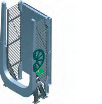
Áporka, Pet Sándor 161. eb: www.gep-hang.hu tel.: +36 20 500 BB METSZET B-B 1:4 A METSZET A-A 1:4 CC METSZET C-C 1:4 D D METSZET D-D 1:4 160 Bronz tárcsa 16 EE METSZET E-E 1:4
68 We chose a worm gearbox solution for the following –reasons:requires relatively little space, – simple and low maintenance, – favorable cost . Due to its self-locking properties, it fits for the intended task great . If the operating personnel interrupts the operation during lifting/lowering for any reason, the bridge will stop and will not move further .

41. ábra: X. sz. öblítőcsatorna-híd – Gépészeti terv részlete / Figure 41 : Mechanical design detail of the bridge of the flushing channel No X 39. ábra: A híd acélszerkezeti tervének részletterve – Pályalemez keresztmetszet / Figure 39 .: Detailed plan of the steel structure of the bridge – Deck plate cross section tűrések. Mérettűrések: MSZ ISO 2768-1m 2338 0,030 kg DIN 93480,140 kg M16x60 8.80,544 kg DIN 1278.0,012 kg M10x20DIN 9338.80,097 kg 08B-1 3140 4,980 kg L=3797 34,657 kg 40x120 Lv5 S355JO0,362 kgTISZA Ø70x250 A608,121 kgTISZA 2Bronz távtartó tárcsaØ120x9,5 Bronz 1,560 kgTISZA 122Bronz távtartó tárcsaØ120x9,5 Bronz 1,415 kgTISZA 148x190x280 17,694 kgTISZA 101Hajtómű tengely öá.Ø127x181,5 2,881 kgTISZA 109x510x700 49,402 kgTISZA 109x510x700 47,887 kgTISZA 71Kézi mozgató öá.250x267x520 9,350 kgTISZA 300x426x543,5 90,516 kgTISZA 51Támasztógörgő öá.180x246x400 23,916 kgTISZA 1185x3170x6797 2879,545 kgTISZA 1650x2800x6525 2880,330 kgTISZA 320x1387x3770 444,783 kgTISZA 11Oszlop 571x1387x3770 511,601 kgTISZA S.sz.Db.Megnevezés
Jelöletlen
To ensure that the resulting gear ratio is such that the speed is not slow when moved by hand, an acceler ator angle drive with a gear ratio of 1 : 2 is integrated in the drive chain . The gearbox was attached on the outsode of the north-east column . The worm gearbox can be rotated by chain drive, with a hand lever, that is located on the same column . The le ver is detachable type to prevent unauthorized use . With the built-in moving mechanism, the bridge can be raised or closed in 1–1 .5 minutes by turning the lever around about 80 times . The force to be applied to the lever is maximum 25 N . In the fully open state, it is necessary to lock the counterweight so that any windstorm that may occur will not damage the structure .
MéretSzabv.AnyagTömegMegjegyzés F METSZET F-F 1:4 DETAN rúd GG METSZET G-G 1:4 2 923 150 1200 8 1305350 6 7 7 10 11 1211 13 14 15 16 17 1819 222021 Jelöletlen tűrések. Mérettűrések: MSZ ISO 2768-1m szerint. Jelöleten tűrések. Alak- és helyzettűrések: MSZ ISO 2768-2m szerint. Hegesztett szerkezetek általános tűrései: MSZ EN ISO 13920-AE szerint. BB AA CC D EE FF METSZET F-F 1:4 DETAN Bronzperselyrúd GG 2 3 4 5 923 150 1200 613053507 9 11 16 17 222021 II PLANNING – SPECIÁLTERV KFT 4 The structure of the Flushing channel No X 40. ábra: AvisVM statikai modell Figure 40 .: Static models in AxisVM
szerint. Jelöleten tűrések. Alak- és helyzettűrések: MSZ ISO 2768-2m szerint. Hegesztett szerkezetek általános tűrései: MSZ EN ISO 13920-AE szerint. Rajzszám: 2014.06.25. TISZA XHídszerkezet öá.Jóváhagyta: 10 11 12 13 14 Fonyódi Emil
– Az emelőkar eltávolítása.
A csigahajtómű forgatása lánchajtással, kézi karral végezhető, ami ugyanezen az oszlopon helyezkedik el. A kar – illetéktelenek használatát megelőzendő – leszerelhető kivitelű.
– A kézi kar forgatásával híd emelése addig, míg a híd oszlopain elhelyezett ellensúlyos reteszelőszerkezetek nem záródnak.
– A kézi hajtómű, a bajonettzáras hajtókar felhelyezése.
– Leengedéskor egy-egy ember az ellensúlyos reteszelő szerkezetet a híd két oldalán oldja, majd a kézi kar segítségével a hidat alsó holtpontig mozgatja.
Hajtóműnek csigakerekes megoldást választottunk ki az alábbi okokból: – viszonylag kevés helyet foglal, – egyszerű és alacsony szintű karbantartási igény, – kedvező költség. Önzáró tulajdonsága miatt nagyszerűen megfelel tervezett feladatnak. Amennyiben a kezelőszemélyzet valamilyen okból emelés/eresztés közben megszakítja a műveletet, akkor a híd megáll, nem mozdul tovább. A kiválasztott hajtómű Bofiglioli VF-130-100. Ennek áttétele i2 = 100, üzemi nyomatéka 1350 Nm. Tervezett terhelésnél fellépő nyomaték Mht = 550 Nm. Így a túlterhelhetőség 2,5-szeres.
A híd részletes gépészeti tervezésére a kiviteli tervek során került sor. Gépészet A tervezés elején a kötélcsörlős megoldás felé indultunk, de ezt a tervezés során elvetettük, mivel a kötél inkább könnyebb szerkezeteknél – járórácsos vagy faszerkezetű – mozgatható hidaknál ad jó megoldást. Hajtóműves mozgatást terveztünk be, az emelőkeret szárán el tudtuk helyezni a fogazott ívet, amelyen keresztül átadtuk gémre a szükséges forgatóerőt. Ennek áttétele i1~6.
69 A híd főbb paraméterei: – támaszköz 6,30 m, – szabad nyílás 5,70 m, – hídszélesség pályalemezen 2,80 m, – teljes szélesség oszlopoknál 2,74 m, – átvezetett út szélessége 2,00 m, – kerékpáros űrszelvény 2,50 m, – alépítmények szélessége 5,50 m. A híd kezelése A híd emeléséhez két ember szükséges. A nyitás–zárás művelete a következő: – A műtárgy lezárása.
Az így felépített mozgató mechanizmussal a hidat a hajtókarnak kb. 80 elfordításával 1–1,5 perc alatt fel lehet emelni, illetve le lehet zárni. A hajtókaron kifejtendő erő max. 25 N.
Teljesen nyitott állapotban az ellensúly reteszelésére van szükség, hogy az esetlegesen fellépő szélvihar a szerkezetet ne károsítsa.
Ahhoz, hogy az eredő áttétel olyan legyen, hogy kézzel mozgatáskor a sebesség ne legyen lassú, ezért egy 1:2-es áttételű gyorsító szöghajtóművet építettünk be a hajtásláncba.Ahajtóművet az északkeleti irányban elhelyezkedő oszlophoz kívülről rögzítettük.
II. TERVEZÉS – SPECIÁLTERV KFT. 4. X. sz. öblítőcsatorna műtárgya
1.1. History, organization For those who want to admire the beautiful natural val ues of Lake Tisza, the cycling around the lake offers a unique experience. For this recreation, cycling on the water embankments south from the main road No. 33 could be done safely for years., however, everyone avoided cycling on the busy main road No. 33 and only admired the beauties of the lake from the car. Hódút Kft. won the tender for the implementation of the cycle path project between Poroszló and Tiszafüred. The task of the project team during this project was to build four bridges, two retaining walls and 6.5 kilometers of cycle path. Between the two settlements, the transport of cyclists had to be solved through several water surfaces. The water surface of Lake Tisza for two times, the river Tisza and one of the channels serving the water supply of the lake had to be crossed. Between the two settlements, in many places the structure of the old, abandoned main road No. 33 could be found, which was replaced by the new main road, which is located higher and protected from water, that was realized at the same time as the formation of Lake Tisza. Using the old road, in many places the bike path has been laid on solid foundations. The road construction connects from the Poroszló protective barrier connection to three different points of Tiszafüred. In Tiszafüred, we drove it close to the Free Beach, the rail way station, the water embankment to the north and the building of the Lake Tisza Cycling Center, which was completed a couple of years ago. The whole trail was very challenging. Two counties, Jász Nagykun Szolnok and Heves counties were also touched with it, as well as two settlements. We also established two railway cross ings near the border of Tiszafüred. During the works, we consulted with the archaeologists and road managers of two counties, three water organizations, the ex perts of the Hortobágy National Park and many other organizations. Besides these, great attention was paid to environmental protection too. We also had to pay at tention to the construction inside the Natura 2000 area, and to the north from the main road No. 33 even in the highly protected areas in our immediate vicinity. We had to plan our works so that we could protect them all. 1.2. Substructures
III III. CONSTRUCTION – HÓDÚT KFT. 1. Eger and Szomorka creek bridges
CONSTRUCTION – HÓDÚT KFT.
70 1 EGER AND SZOMORKA CREEK BRIDGES
The construction of the Eger and Szomorka creek bridges was made a real challenge by the fact that be fore the formation of Lake Tisza, two creeks flowed in these places, but when the lake was swollen, large, wide water surfaces formed here. In the lowland area, which has been covered with water for almost 50 years, un der the about 1 meter deep water, 2.0–2.5 meters of mud
Az Eger- és Szomorka-patak-hidak kivitelezését az tette igazán nagy kihívássá, hogy a Tisza-tó kialakítása előtt ezeken a helyeken két patak folydogált, azonban a tó felduzzasztásakor itt nagy, széles vízfelületek alakultak ki. A közel 50 éve vízzel borított alföldi területen körülbelül 1 méter mélységű víz alatt 2,0–2,5 méter iszap található. A hidak helyét így nehéz volt megközelíteni. A bárkákról, úszóművekről történő folyami hídépítés a kis vízmélység miatt nem volt megoldható, ezért más technológia mellett kellett döntenünk, hogy minden körülmény mellett be tudjuk juttatni a kivitelezéshez szükséges eszközöket. A Közép-Tisza-vidéki Vízügyi Igazgatóság szakembereivel egyeztetve építettünk kőanyagból bejáróutakat az Eger- és Szomorka-patak-hidakkal párhuzamosan, a támaszoknál és járomhelyeknél félszigeteket képezve. Így már biztonsággal le tudta fúrni a CFA technológiával kivitelezendő cölöpöket a fúrógép, le tudtuk vibrálni a szádlemezeket az alépítményi szerkezetek kivitelezési munkagödréhez.
1.1. Előzmény, organizáció A Tisza-tó gyönyörű természeti értékeit megcsodálni vágyóknak a tó körbe kerékpározása páratlan élményt nyújt. Ehhez a kikapcsolódáshoz a 33. sz. számú főúttól délre, a vízügyi töltéseken a kerékpározás már évek óta biztonságosan megtehető volt, azonban a nagy forgalmú 33. sz. főúton mindenki kerülte a kerékpáros közlekedést és csak autóból csodálta a tó szépségeit. A Poroszló Tiszafüred közötti kerékpárút megvalósítása projekt kivitelezésére kiírt pályázatot a Hódút Kft. nyerte el. A projektcsapat feladata ennek keretében négy híd, két támfal és 6,5 kilométer kerékpárút megvalósítása volt. A két település között több vízfelületen keresztül kellett megoldani a kerékpárosok átközlekedését. Keresztezni kellett két helyen a Tisza-tó vízfelületét, a Tisza folyót és a tó vízutánpótlását szolgáló egyik csatornát is. 1.2. Alépítmények
III. KIVITELEZÉS – HÓDÚT KFT. 1. Eger- és Szomorka-patak-hidak III
71 1 EGER- ÉS PATAK-HIDAKSZOMORKA-
A munkagödör kiemelése után a vasbeton cölöpösz szefogók és egyedi keresztmetszetű pillérek kialakítása következett. A pillérek alakja illeszkedik a híd felszerkezet kecses, légies formájához. A vízszintes keresztmetszete ellipszis formájú, és mindez tölcséresen nyílik felfelé. A kis keresztmetszet és belső erők eredményeként a pillér fővasai 40 mm átmérővel rendelkeznek, valamint a pillérekbe nagy átmérőjű, M42 mm keresztmetszetű menetes szárakat és egyéb bebetonozandó acélszerkezeteket is el kellett helyezni az acél felszerkezet lekötéseMindezekcéljából.összessége
miatt a pillér építését csakis nagyfokú precizitás mellett lehetett megoldani. Egyszerűen szólva, mindennek passzolnia kellett. A Magyar
KIVITELEZÉS–HÓDÚTKFT.
The main supporting elements of both the Eger creek bridge and the Szomorka creek bridge, the 610 mm diameter steel pipes of varying wall thickness, were manufactured by the German-based company Mannes mann . It was expedient to book the production capacity to the full quantity, therefore the pipes required for the production of the Eger creek and Szomorka creek bridge Eger and Szomorka creek
III CONSTRUCTION – HÓDÚT KFT 1
For schedule reasons, the construction of the Eger creek and Szomorka creek bridge started after the start of the production of the Tisza bridge structure, in par allel with it .
The abutments of the Eger and Szomorka creek bridges also rely on CFA pile foundations, which we had to build on the slope of the previous road bridge embankment . This was also possible with a sheet pile workspace delimitation, as the piling machine required a horizontal working level for the piling and the abut ment front walls, together with the wing walls, could be constructed from here . 1.3. Manufacturing
The production of the steel structure of the Eger creek bridge (383 t) was in the halls of BANIMEX Sp.z o.o. the group’s plant in southern Poland, while the elements of the Szomorka creek bridge (112 t) were manufactured in Sárospatak – in the production plant of Weinberg ’93 Kft . – in order to ensure the indicators of capacity plan ning and the sustainability of the tight schedule
72 can be found . Because of this, the location of the bridges was difficult to access. The construction of river bridges from barges and floating platforms was not possible due to the small water depth, therefore, we had to choose a different technology so that we could deliver the devices needed for the construction to the site under all circum stances . After consulting with the experts of the Central Tisza Region Water Directorate, we built stone access road embankments parallel to the Eger and Szomorka creek bridges, forming peninsulas at the supports and temporary supports . This allowed the drilling machine to safely drill piles with CFA technology, we were able to vibrate the sheet piles for the construction pit of the substructure . After the excavation of the construction pit the next step was the construction of reinforced con crete pile clamps and custom cross-section pillars . The shape of the pillars matches the slim, airy shape of the bridge superstructure . Its horizontal cross-section is el liptical in shape and opens as a funnel upwards As a result of the small cross section and internal forces, the main steel reinforcements of the pillar have a diame ter of 40 mm . In addition, large-diameter threaded rods with an M42 mm cross-section and other steel struc tures to be concreted had to be placed in the pillars in order to fix the steel suterstructure. Due to all of these, the construction of the pillar could only be done with a high level of precision . To put it simply, everything had to fit. Magyar Doka Zsalutechnika Kft. undertook the production of the custom shaped pillar formworks, of which three sets were rotated by the structural con struction company RO-LY BAU Kft in order to imple ment the pillars in a timely manner . The built access road embankment was also suitable for piling, work space delimitation, the construction of reinforced con crete structures of the substructure and the transpor tation and lifting of the steel superstructure with over sized vehicles to its final place. We were able to carry out from it all the finishing work on the bridge, from the placing of the bearings, through the concreting of the lower parts of the main girder arches, to the cor rosion protection . After the construction of the bridges, there was little time to break down our access road em bankment and give back the spacious surface of water to wildlife . In about three weeks, we had to retrieve and transport 15,000 tons of andesite stones while preserving the already built bike path
.
bridges
III. KIVITELEZÉS – HÓDÚT KFT. 1. Eger- és Szomorka-patak-hidak
Mind az Eger-patak-híd, mind a Szomorka-patak-híd fő tartóelemeit, a 610 mm átmérőjű, variálódó falvastagságú acélcsöveket a németországi székhelyű Mannesmann cég gyártotta. A gyártókapacitás lekötését a teljes mennyiségre volt célszerű megtenni, ezért az 19 kép: Pillér vasalása és kizsaluzott vasbeton szerkezete / Picture 19 : Pillar reinforcement and the reinforced concrete structure 20. kép: Eger-patak-híd pihenőhelye alatti pillér/ Picture 20 : Arch supporting element of the Eger creek bridge under the resting place


73 Doka Zsalutechnika Kft. vállalta az egyedi formájú pillérzsaluzatok legyártását, melyből három készletet forgatott a RO-LY BAU Kft. szerkezetépítő vállalat a pillérek ütemes kivitelezése érdekében. Az épített bejáróút alkalmas volt a cölöpözés, a munkatér-határolás kialakítására, az alépítményi vasbeton szerkezetek kivitelezésére és az acél felszerkezet túlméretes járművekkel való beszállítására, beemelésére. El tudtuk végezni róla a híd minden befejező munkáját a saruzástól kezdve a főtartó ívek alsó kibetonozásán át, a korrózióvédelemmel bezárólag. A hidak kivitelezése után kevés idő állt rendelkezésre, hogy a bejáróutunkat visszabontsuk és visszaadjuk a tágas vízfelületet az élővilágnak. Körülbelül három hét leforgása alatt kellett 15 000 tonna andezit követ visszanyernünk és elszállítanunk a megépített kerékpárút megóvása mellett. Az Eger- és Szomorka-patak-hidak hídfői is CFA-cölöpalapozásra támaszkodnak, melyeket az eddigi közúti híd töltésrézsűjében kellett kiviteleznünk. Ez szintén szádlemezes munkatér-határolás mellett volt megvaló sítható, mivel a cölöpözőgépnek szükséges volt egy vízszintes cölöpözési lavírsík kialakítása, és a hídfő felmenőfalakat a szárnyfalakkal együtt innen tudtuk kivitelezni. 1.3. Gyártás Az Eger-patak-híd (383 t) acélszerkezetének gyártása a cégcsoport dél-lengyelországi gyárában, a BANIMEX Sp.z o.o. csarnokaiban, történt, míg a Szomorka-patak-híd (112 t) elemeinek gyártása a kapacitástervezés mutatói és a szoros ütemterv tarthatósága érdekében Sáros patakon – a Weinberg ’93 Kft. gyártóüzemében – történt. Ütemtervi megfontolásból az Eger-patak- és Szo morka-patak-híd gyártása a Tisza-híd szerkezet gyártásának kezdetét követően, azzal párhuzamosan történt.

creek bridges
Only the finished bent pipe main girders were trans ported to the production plants – in Będzin in southern Poland and in Sárospatak. The arc radius of the curved supports for the Eger creek and Szomorka creek bridge is between 15 and 63 meters, and their wall thickness is in the 10 and 60 mm range. The lightness of the structures and the beauty of the bridges are given by the dynamic lines and curves formed from these bent pipes.
III. CONSTRUCTION – HÓDÚT KFT. 1. Eger and
The main test of this machine was the production of components for bridges in Poroszló, where, of course, it performed its task flawlessly, saving very significant amount of man-hours and guaranteeing a precision production compared to traditional machining.
One of the biggest challenges was to manufacture and assemble curved pipe supports according to the de sign specifications, because the base line cannot be well defined on the pipe elements, which is the basis of all measurements during production.
The different types of assembly units required the creation of a production devices, fixtures and templates, because this was the only way to ensure that the re quired geometry was kept within tolerance and that the connecting elements could be assembled on site. The ac curacy of the production and assembly was ensured by optical and laser leveling and measuring instruments, inspection arc templates, specially pre-manufactured for the project, bases fixed and accurately measured for the assembly devices and significantly more intensive engineering supervision than usual. Even the applica tion of these at one time, created a serious challenge to those who were involved in manufacturing and on-site assembly.Theproduct design required even closer cooperation between the Designer and the Constructor in the case of the bicycle bridges between Poroszló and Tiszafüred, due to the custom, non-typeable pipe-pipe intersections and the internal forming of the structure. Continuous optimization was required to ensure the relationship between design of the welds and their feasibility, which was only possible with continuous and smooth commu nication between the Welding Supervision department of Hódút Kft. and the design team of Speciálterv Kft. The lightness of the structure allowed the application of a single main girder design, although the support re actions increased inversely due to the eccentric effects. It would have been possible to absorb the arising sup porting forces only by using a robustly designed “clas sic” bearing element., which would have resulted in a significant expense and a break in the harmony of the 21. kép: Eger-patak- és Szomorka-patak-híd csőfőtartóinak hajlítása / Picture 21.: Bending of the main girder pipes of the Eger creek and Szomorka creek bridge Szomorka
74 were transferred from the same rolling mill to the Ker sten Europe plant in the Netherlands, where the pipes were bent.
Within the BANIMEX’s technological development program, a high-tech, plasma cutting machine that is capable of 3D cutting too, with a 28 meter long table was also purchased, with which both plates and pipes can be machined, including the formation of welding edges or pipe intersection curves.

A gyártmánytervezés a Poroszló Tiszafüred közötti kerékpároshidak esetében még szorosabb együttműködést kívánt meg Tervező és Kivitelező részéről, az egyedi, nem tipizálható cső–cső áthatások és a szerkezet belső kialakítása miatt. Folyamatos optimalizálás volt szükséges a hegesztési varratok tervezése és kivitelezhetőség kapcsolatának biztosításaként, mely a Hódút Kft. Hegesztésfelügyelete és a Speciálterv Kft. tervező csapata közötti folyamatos és gördülékeny kommunikációval volt csak lehetséges. 22. kép: Eger-patak- és Szomorka-patak-híd hajlított csőfőtartói /
75 Eger-patak- és Szomorka-patak-híd gyártásához szükséges csöveket ugyanazon hengerműből szállítottuk át Hollandiába a Kersten Europe üzemébe, ahol a csövek hajlítása történt. A gyártóüzemekbe – a dél-lengyelországi Będzin-be, valamint Sárospatakra – már csak a kész hajlított cső főtartókat szállítottuk át. A hajlított tartók ívsugara az Eger-patak- és Szomorka-patak-híd esetében 15 és 63 méter közötti, a falvastagság a 10 és 60 mm tartományba esik. A szerkezetek könnyedségét, a hidak szépségét éppen az ezekből a hajlított csövekből kialakuló lendületes vonalak és ívek adják.
A BANIMEX technológiai fejlesztési programja keretében egy csúcstechnikát képviselő, 28 méter asztal hosszúságú, 3D vágásra alkalmas plazmavágó gép beruházására is megtörtént, amellyel lemezek és csövek egyaránt megmunkálhatók a hegesztési élkiképzést vagy a csövek áthatási vonalait is beleértve. Ennek a gépnek a főpróbáját éppen a poroszlói hidak alkatrészgyártása jelentette, ahol természetesen hibátlanul végezte a feladatát, nagyon jelentős munka óra-ráfordítást megtakarítva és méretpontos gyártást garantálva a hagyományos megmunkáláshoz képest. Az egyik legnagyobb kihívás az íves csőtartóknak a tervezői előírások szerinti gyártása és összeállítása volt, mivel a csőelemeken nem definiálható jól bázisvonal, ami a gyártás során minden mérés alapja. A különböző típusú szerelési egységekhez gyártókészülék és sablon készítése volt szükséges, mert egyedül ezáltal volt biztosítható az előírt geometria tűrésen belül tartása és a csatlakozó elemek helyszíni szerelhetősége. A gyártás és összeszerelés pontosságát optikai és lézeres szintező- és mérőműszerekkel, speciálisan a projekthez előre legyártott ellenőrző ívsablonokkal, az összeállító készülékekhez rögzített és pontosan bemért bázisokkal és a szokásosnál lényegesen intenzívebb mérnöki felügyelettel biztosítottuk. Még ezek együttes alkalmazása is komoly kihívás elé állította a gyártásban és a helyszíni szerelésben résztvevőket.
Picture 22.: The bent pipe main girders of Eger creek and Szomorka creek bridges 23. kép: Munkában az új 3D plazmavágó berendezés /

Picture 23.: New 3D plasma cutting machine at work III. KIVITELEZÉS – HÓDÚT KFT. 1. Eger- és Szomorka-patak-hidak

The supporting element is connected to a receiving plate with M42/M50 threaded shanks, previously con creted into the pillars of individual geometry. During the production of the bridge elements, we de cided to keep the full cross-sectional width of 3.91 m, considering the limitations of road transportation and also the increased time and capacity that is required for the on-site installation. For on-site assemblability, the assembly allowances were formed at the end of the elements in each span with a length of 100 mm. Prior to transportation, the trial assembly of the ele ments was done in accordance with the production or der. It is a very impressive sight when a small part of a complicated spatial geometry structure shows itself in the factory hall during trial assembly and projects the beauty of the future bridge.
76 bridge structure at the same time. This is how the sup port element suitable for absorbing longitudinal move ments and the tearing up forces was born, the so-called “Sausage-filler”.

24. kép: A „hurkatöltő” támasz (Eger-patak- és Szomorkapatak-híd támaszelem) /
Picture 24.: The "Sausage-filler" support (Eger creek and Szomorka creek bridge supporting element)

25. kép: Szomorka-patak-híd – pálya próbaszerelése / Picture 25.: Trial assembly of Szomorka creek bridge deck 42. ábra: Eger-patak-híd – Elemosztás / Figure 42.: Eger creek bridge element distribution III. CONSTRUCTION – HÓDÚT KFT. 1. Eger and Szomorka creek bridges
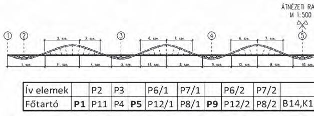
A szerkezet könnyedsége tette lehetővé az egyfőtar tós kialakítást, bár a támaszreakciók ezzel fordított arányban nőttek a külpontos hatások miatt. A fellépő támaszerőket csak robusztus kialakítású, „klasszikus” sarugyártmány alkalmazásával lett volna lehetséges fel venni, mely jelentős ráfordítást és egyben a hídszerkezet összhangjának megbontását eredményezte volna. Így született meg a hosszirányú mozgások és a felszakító erők felvételére alkalmas támaszelem, az ún. „hurka


26.töltő”.kép: Bebetonozandó elemek „hurkatöltő” fogadásához / Picture 26.: Elements to be concreted to receive the “Sauseage-filler” 27. kép: Eger-patak-híd P1-P11 elemek próbaszerelése / Picture 27.: Trial assembly of the P1-P11 elements of Eger creek bridge III. KIVITELEZÉS – HÓDÚT KFT. 1. Eger- és Szomorka-patak-hidak

77

During the on-site assembly, due to the width limita tions of the access road embankment, the location of the combination vehicle that was carrying the bridge ele ment and the crane that was doing the lifting was only possible on the same axle, which in the case of the larg er elements required the deployment of a mobile crane with a load capacity of 160–200 tonns for both bridges.
The on-site assembly of the Szomorka creek bridge could have been carried out in two phases due to the forced redesign of the foundations of the abutments. In the first phase, the intermediate bracing brackets and main supporting elements were put in place, then, after the abutments were completed, the side elements were alsoTheassembled.PFEIFER UMIX system suspension bars were in stalled after the assembly of the main supports of the 28. kép: Szomorka-patak-híd – Építés közben / Picture 28.: Szomorka creek bridge under construction HÓDÚT KFT. 1. Eger and Szomorka creek bridges

78 1.4. On-site installation When planning the on-site construction technology, the main consideration was that the official diversion route of the large project running in parallel on the Tisza, a few river kilometers away, was the main road No. 33. As a result of this, the traffic on the main road could not be significantly restricted. The access road embankment mentioned in the previous chapter ensured undisturbed construction under all circumstances. It was a great challenge for the transporting com panies to forward the oversized bridge elements that were 3.91 m wide, 12–22 m long and 0.8–3.5 m high, in many cases weighing ~30 tonns, that could enter the road traffic only in the evening. A special solution was needed to maintain the stable condition of the support elements during transport that had a high center of gravity, resulting from the designed shape. This could be ensured by using transport cradles specially designed for this purpose.
The structural geometry of the Eger creek and Szo morka creek bridges is very similar, so the assembly of both bridge structures could be served by the production of 7 steel temporary support structures and their ap propriate logistics.
III. CONSTRUCTION –
The on-site installation was carried out by ACÉLHI DAK Kft. On behalf of Hódút Kft., in such a direct way that the manufactured, trial assembled bridge elements were immediately lifted from the transport vehicles to their intended location. Stability during installation was provided by the custom made prefabricated re inforced concrete pillars and steel temporary support structures installed on both sides of them.
A helyszíni kivitelezési technológia tervezésekor fő szempont volt, hogy a Tiszán pár folyamkilométerre párhuzamosan futó nagyprojekt hivatalos terelőútja a 33. sz. főút volt. Ennek eredményeként a főút forgalma nem volt korlátozható jelentős mértékben. Az előző fejezetben említett betöltés biztosította minden körülmény mellett a zavartalan kivitelezést. Nagy kihívás volt a szállítmányozó cégek számára a 3,91 m széles, 12–22 m hosszú és 0,8–3,5 m magas, több esetben ~30 t tömegű túlméretes hídelemek szállítása, melyek kizárólag este léphettek be a közúti forgalomba. Külön megoldást kívánt a tervezett formából adódó magas súlypontú támaszos elemek stabil állapotának fenntar29. kép: Szomorka-patak-híd – T2 jelű elem beemelése / Picture 29.: The lifting of T2 bridge element of Szomorka creek bridge HÓDÚT KFT. 1. Eger- és Szomorka-patak-hidak
A helyszíni szerelhetőség érdekében a szerelési ráhagyásokat minden pillérközben egy elemvégen alakítottuk ki 100 mm hosszban. A szállítást megelőzően – a gyártási sorrendnek megfelelően – történt az elemek próbaszerelése. Igen impozáns látvány, amikor egy bonyolult térgeometria próbaszerelése során már a csarnokban megmutatja magát a szerkezet kis része, és előrevetíti a majdani híd szépségét. 1.4. Helyszíni szerelés

79
A támaszos elem az egyedi geometriájú pillérekbe előzőleg bebetonozott fogadó lemezhez, M42/M50 menetes szárakhoz csatlakozik, A hídelemek gyártása során a teljes 3,91 m keresztmetszeti szélesség megtartása mellett döntöttünk, mérlegelve a közúti szállítás korlátait, a helyszíni szerelés többletidő- és kapacitásigényét is.
III. KIVITELEZÉS –

32. kép: Eger-patak-híd – Ívtartó szerelése / Picture 32.: Eger creek bridge arch girder installation

III. CONSTRUCTION – HÓDÚT KFT. 1. Eger and Szomorka creek bridges

80 arch, which were tensioned by raising the suspended brace bracket section by a specified increasement of the reaction force and then releasing it. After the bar ten sionings, it was necessary to perform a geometric check in each case, which confirmed the success of the ten sioning.Theinstallation
Picture 31.: Szomorka creek bridge access road embankment and assembly site

of the Eger creek bridge was continuous moving from Poroszló to Tiszafüred. While the access road embankment filled into Lake Tisza along the Szomorka creek bridge was in the full-width, in the riverbed of the Eger creek, it was necessary to contin uously ensure an unobstructed flow through 1.8 m di ameter Rocla culverts pre-built into the embankment of the access road. On the “river” section that had to be kept, temporary supports installed on pipe piles served as supports for the lifting of the bridge elements. In case of the on-site installation of the Eger creek bridge, the installation of the elements was always ac complished from support to support. The main supporting girders that were lifted onto the pre-concret ed M50/M42 threaded rods formed on the pillars were followed by the intermediate bracing brackets, which were supported on temporary auxiliary supports. Dur ing production, after cutting the 100 mm mounting al lowance formed at the end of each bracing bracket, the assembly of the given span became continuous. The arch supports were lifted and installed with the help of the arch assembling scaffolds designed for this purpose.
30. kép: Szomorka-patak-híd – T2 jelű elem érkezése / Picture 30.: The arrival of the T2 element of the Szomorka creek bridge
31. kép: Szomorka-patak-híd – Betöltés és szerelőterület /
Az ívfőtartók szerelését követően helyeztük be a PFEIFER UMIX rendszerű függesztőrudakat, melyek feszítése a függesztett merevítőtartó-szakasz meghatározott reakcióerő-növekménnyel történő megemelése, majd visszaengedése által zajlott le. A rúdfeszítést követően minden esetben geometriai ellenőrzést volt szükséges végrehajtani, mely igazolta a feszítés sikerességét.AzEger-patak-híd szerelése Poroszló felől Tiszafüred felé haladva folytonosan történt. Míg a Szomorka-patak-híd mentén a Tisza-tóba történt betöltés teljes mederszélességű volt, az Eger-patak medrében egy pillérközben folytonosan szükséges volt biztosítani az akadálymentes átfolyást a betöltésbe előre beépített 1,8 m átmérőjű Rocla átereszek mellett. A fenntartandó „folyó” szakaszon csőcölöpökre telepített jármok szolgáltak támaszként a hídelemek beemelésekor.
A Szomorka-patak-híd helyszíni szerelése két ütemben valósulhatott meg a hídfőalapozások kényszerű áttervezése miatt. Első ütemben a közbenső merevítőtartók és főtartó elemek kerültek a helyükre, majd a hídfők elkészülte után a szélső elemek szerelése is megtörtént.

81 tása szállítás közben, mely külön erre a célra tervezett szállító bölcsők alkalmazásával volt biztosítható. A helyszíni szerelést Hódút Kft. megbízásából ACÉLHIDAK Kft. in-szitu végezte, azaz a legyártott, próbaszerelt hídelemeket a szállító járművekről emelték be egy ből a tervezett helyükre. A szerelés közbeni stabilitást a már előzőleg elkészült egyedi vasbeton pillérek és azok két oldalán telepített acél járomszerkezetek adták. A helyszíni szerelés során a betöltés szélességi korlátai miatt a hídelemet szállító trailer és a beemelést végző daru elhelyezkedése csak egy tengelyben volt lehetséges, mely a nagyobb elemek esetében 160–200 t teherbírású autódaru felvonultatását igényelte mindkét híd esetében. Az Eger-patak- és Szomorka-patak-híd szerkezeti geometriája nagyon hasonló, így 7 darab acél járomszerkezet gyártásával és azok megfelelő logisztikájával mindkét hídszerkezet szerelése kiszolgálható volt.
Az Eger-patak-híd helyszíni szerelése során az elemek beépítése mindig támasztól támaszig tartott. A pilléreken kialakított, előre bebetonozott M50/M42 menetes szárakra daruzott támaszos főtartó elemeket a közbenső merevítőtartók követték, melyek alátámasz tása az ideiglenes segédjármokon valósult meg. A gyártás során az egyes merevítőtartók végén kialakított 100 mm szerelési ráhagyás levágása után vált folytonossá a szerelésbe fogott támaszköz.
Az ívtartók beemelése és szerelése az erre kialakított ívszerelő állványok segítségével történt.
A függesztőrudak feszítése a Szomorka-patak-hídon ismertettek szerint zajlott, annyi módosítással, hogy a feszítés mindig a következő támaszköz ívtartójának szerelése után valósulhatott meg.
III. KIVITELEZÉS – HÓDÚT KFT. 1. Eger- és Szomorka-patak-hidak
A szerkezetek a funkciójuk és elhelyezkedésük alapján egyaránt érzékenyek a gyalogosok, illetve a szél által keltett dinamikus gerjesztésre. A sajátfrekvenciák elhangolása érdekében a csőfőtartókat szakaszosan kibetonoztuk.
33. kép: Szomorka-patak-híd szerkezete a víz felett / Picture 33.: Szomorka creek bridge structure over the water 34. kép: Pihenőhely a Szomorka-patak-hídon Picture 34.: Resting place on Szomorka creek bridge
The tensioning of the suspension bars was carried out as described at the Szomorka creek bridge, with such modifications that the tensioning could always take place after the installation of the arch support of the next span. Based on their function and location, the structures are sensitive to dynamic excitation forces by pedestrians and the wind. In order to detune the natural fre quencies, the pipes of the main supports were intermit tently filled with concrete. The corrosion protection of the bridge elements was performed by COLOR HELP Kft. both in the plant and on site, thus reaching the final 320 µm dry layer thickness of the coating. During the choosing of the color, we considered it important that the symbolic status and airiness of the bridge structures be both accentuated and aesthetic. As a result of consultations with the Cus tomer and the prospective Operator, the color RAL 9018, papyrus white was determined as the covering layer of the bridge structures. The construction of the substructure, superstructure and the complete logistics of the Eger and Szomorka creek bridges was a great challenge for the team, which involved considerable effort, but the sight of the com pleted bridge overwrites all strenuous work. When we turn at the end of Poroszló onto the straight road lead ing to Tiszafüred, the arches of the Eger creek bridge al ready shine among the poplars of the coast. From there, one only watches curiously, what great structures have actually been made here. It doesn’t take a long time for the bridges just done, to become real symbols of Lake Tisza, for which the Eger creek bridge has the great est chance of competing with its dignity and length, but with a structure that is still airy and graceful.

III. CONSTRUCTION – HÓDÚT KFT. 1. Eger and Szomorka creek bridges

szerkezeti
volt a csapat részére, mely nem kis fáradtsággal járt, azonban az elkészült híd látványa felülír minden korábbi erőfeszítést. Amikor Poroszló végén rákanyarodunk a Tiszafüred felé vezető egyenesre, már az Eger-patakhíd ívei tündökölnek a parti nyárfák között. Onnantól az ember csak kíváncsian figyeli, milyen nagyszerű szerkezetek készültek is itt valójában. Nem sok idő kell ahhoz, hogy a most készült hidak igazi jelképei legyenek a Tisza-tónak, melyre a négy darab most készült híd közül méltóságával, hosszával, de mégis légies, kecses szerkezetével az Eger-patak-híd pályázik a legnagyobb eséllyel.
A hídelemek korrózióvédelmét COLOR HELP Kft. végezte üzemben és helyszínen, így nyerte el a bevonat végleges 320 µm száraz rétegvastagságát. A színválasztás során fontosnak tartottuk, hogy a hídszerkezetek jelkép státusza és légiessége egyaránt hangsúlyos, esztétikus legyen. A Megrendelővel és leendő Üzemeltetővel történt egyeztetés folyományaként a hídszerkezetek fedőrétegeként RAL 9018 papiruszfehér színt határoztukAzmeg.Eger- és Szomorka-patak-hidak alépítményi, felés teljes logisztikai kivitelezése nagy kihívás
35. kép: Eger-patak-híd / Picture 35.: Eger creek bridge III. KIVITELEZÉS – HÓDÚT KFT. 1. Eger- és Szomorka-patak-hidak


84 2 TISZA BRIDGE 2.1 History, organization
When preparing for the construction, we held a site visit through the entire section of the bike path. However, the area around the Tisza bridge caused us the biggest headache, how could it be implemented. From the north, the railway bridge of the Debrecen – Füzesabony rail way line and the road bridge of the main road No. 33 line up. The next row would show a more complete picture of the transport: railway bridge, road bridge and a bicycle bridge. The fact made the implementation even harder that on the right bank of river Tisza the Fisher man’s Tavern is located in the immediate vicinity of the road bridge. Should we even have space for a bike path, a bridge there?– we asked the question. Then we took a closer look and yes, the bike path has to be there. On the dirt roads hidden on the left bank, it was possible to enter the floodplain that is under the railway and road bridges. Here, we finally built an access road embank ment and a staging area of around 6,000 square me ters for the facilities and colleagues assembling the steel structure and to build the assembly tracks and launch ing track. The trial pile test of the Tisza Bridge was also carried out here. 2.2. Substructures, cantilevers
Zsalutechnika Kft. and RO-LY BAU Kft., the supporting scaffolding system was developed and it’s working level of which was used to safely load the concreting of the new cantilevers and to implement all this in the air, above the river Tisza.

After the construction of the working levels, the covering concrete “bark” of the pier caps of the exist ing road bridge was removed and carved to a depth of 10–15 centimeters, so that by connecting it more pre cisely to the existing reinforced concrete structure, we could build the reinforced, sheathed, cantilevered pier cap based on the plans of Speciálterv Kft. More than 550 shear studs per pillar had to be drilled and glued to each pier cap with high strength adhesive. In case of each cantilever a total of about 12 000 kg re inforced steel was installed. Due to the poor condition of the existing pier caps, we also had to drill them through in the bearing axles and in the transverse bearing zone we had to provide a subsequent tensioning force on them. This was finally solved with 36 millimeter diam eter Dywidag rods. We can say that it was a complex task to implement all these over the water of Tisza and 36. kép: Tisza-híd – Fejgerenda tüskézése / Picture 36.: Tisza bridge pier shear studs
III. CONSTRUCTION – HÓDÚT KFT. 2. Tisza bridge
The construction of the cycling Tisza bridge was a great challenge. We had to supplement each of the existing pillars of the road bridge, built in the 1800s and rebuilt several times, standing in water, with reinforced con crete cantilevers, but there were space constraints too. By the end of the joint negotiations with Magyar Doka
37. kép: Tisza-híd – Fejgerenda visszavésése
85 2 TISZA-HÍD 2.1. Előzmény, organizáció
A kivitelezés előkészületekor bejárást tartottunk a kerékpárút teljes szakaszán. A Tisza-híd környéke okozta azonban a legnagyobb fejtörést, hogy hogyan is lehetne azt megvalósítani. Északról sorban a Debrecen –Füzesabony vasútvonal vasúti hídja, valamint a 33. sz. főút közúti hídja sorakoznak. A közlekedésről teljesebb képet mutatna a következő sor: vasúti híd, közúti híd és egy kerékpároshíd. Tovább nehezítette a megvalósítást, hogy a Tisza jobb partján a halászcsárda a közúti híd köz vetlen közelében fekszik. Oda kellene még férnünk egy kerékpárúttal, híddal is? – tettük fel a kérdést. Majd megnéztük közelebbről, és igen, ott kell legyen a kerékpárút. A bal parton elrejtett földutakon be lehetett jutni a vas úti és közúti hidak alatt elterülő hullámtérre. Itt építettünk végül bejáróutat és nagyságrendileg 6000 négyzet méteres szerelőterületet a felvonulási létesítményeknek és az acélszerkezetet összeállító kollégáknak a szerelőpályák és tolópálya kialakítására. Itt valósult meg a Tisza-híd próbacölöp vizsgálata is. 2.2. Alépítmények, konzolok A kerékpáros Tisza-híd építésének nagy kihívása volt a közúti híd meglévő, 1800-as években készült, többször újjáépített, felújított, vízben álló pillérjeinek kiegészí tése egy-egy vasbeton konzollal, valamint a helyszűke. A Magyar Doka Zsalutechnika Kft.-vel és RO-LY BAU Kft.-vel történő közös egyeztetések végére kialakult az az alátámasztó állványrendszer, munkaszint, mely alkalmazásával biztonságosan terhelhető volt az új konzolok betonozása, és meg is valósítható a Tisza fölött a levegőben.Amunkaszintek kiépítése után következett a meglévő közúti fejgerendák betontakarási „kérgének” eltávolítása, levésése 10–15 centiméter mélységig, hogy a meglévő vasbeton szerkezethez precízebben csatlakozva meg tudjunk építeni az erősített, köpenyezett, konzollal ellátott fejgerendát a Speciálterv Kft. tervei alapján. Pillérenként több mint 550 darab betonacél tüskét kellett
Picture 37.: Carving of the Tisza bridge pier cap 38. kép: Tisza-híd – Fejgerenda vasszerelése / Picture 38.: Installation of the reinforcement of Tisza-bridge pier cap III. KIVITELEZÉS – HÓDÚT KFT. 2. Tisza-híd


under the structure of the road bridge: scaffolding, re inforcing steel assembly, concreting, and post-tension ing tasks and all related work phases. But we got richer with unforgettable challenges and for the unique beauty of the bridge, it was worth doing all these too. The abutments, unlike the internal supports, rely on an independent pile foundation. The challenge was really provided by the small area between the road bridge and the F isherman’s Tavern. Applying the sheet pile workspace delimitation and embankments located next to the road bridge, we were able to get the 96 ton pil ing machine to a small, narrow and high place, where it was able to drill the piles using CFA technology, only a few centimeters far from the road bridge. After that, piling at the abutment on the left riverbank, towards Tiszafüred was less of a challenge for us. Although here, too, construction of embankments and the delimitation of workspaces with sheet piles became necessary for the implementation of the piling, the abutments and the connecting “U” shaped retaining walls. These retaining walls lead cyclists up to the Tisza Bridge, providing safe support for both abutments.
39.
2.3. transportationManufacturing, The production of the steel structure of the Tisza bridge (362 t) – was chronologically before the production of the Eger creek bridge -in the halls of BANIMEX Sp.z o.o. the group’s plant in southern Poland. Although the total weight of the structure lags behind bridges with similar spans, the complexity of the design and the entire construction process rivals with the time and capacity consumption of those. The main supporting elements of the structures are the seamless 406 mm diameter pipes, which in the case of the Tisza bridge were manufactured by the Báthory pipe factory in Poland. The radius of curvature of the bent supports is 75 meters. About the structural junc tions of the Tisza bridge – similarly to the previous two bridges – can also be said to abound in custom pipeto-pipe intersections, which were cut with a 3D plasma cutting device. kép: Tisza-híd – Elkészült fejgerenda / Picture 39.: Tisza bridge finished pier cap Tisza bridge
III. CONSTRUCTION – HÓDÚT KFT. 2.

III. KIVITELEZÉS – HÓDÚT KFT. 2. Tisza-híd
A szállításokat megelőzően minden hídelemet próbaszereltünk, ellenőrizve a megadott szigorúbb tűréseket.
87 befúrni, és nagy szilárdságú ragasztóval beragasztani minden egyes Konzolonkéntfejgerendába.nagyságrendileg összesen 12 000 kg betonacél szerelése valósult meg. A meglévő fejgerendák rossz állapota miatt sarutengelyekben átfúrással, azokat keresztirányban saruzónában utólagos feszítéssel is el kellett látnunk. Ezt végül 36 milliméter átmérőjű Dywidag-rudakkal oldottunk meg. Mondhatjuk, hogy a Tisza fölött és a közúti híd felszerkezete alatt összetett feladat volt megvalósítani mindezeket: az állványozást, a betonacél-szerelést, a betonozást, valamint az utólagos feszítési feladatokat és minden kapcsolódó munkafázist. De felejthetetlen kihívásokkal lettünk gazdagabbak, és a híd páratlan szépségéért ezt is megérte végigcsinálni.Ahídfőka belső támaszokkal ellentétben független cölöpalapozásra támaszkodnak. A kihívást igazából a közúti híd és a halászcsárda közti kevés terület szolgáltatta. A közúti híd mellett elhelyezett szádlemezes munkatér-határolás és töltéstestek alkalmazásával sikerült bejuttatnunk a 96 tonnás cölöpözőgépet egy kis szűk és magas helyre, ahol le tudta fúrni a közúti hídtól pár centiméterre elhelyezkedő CFA technológiájú cölöpöket. Ezek után a Tiszafüred felé eső, bal parti hídfő cölöpözése már kisebb kihívást jelentett számukra. Bár itt is töltéstestek építése és szádlemezes munkatér-határolás vált szükségessé a cölöpözés kivitelezéséhez, a hídfők és a csatlakozó „U” alakú támfalak megépítéséhez. Ezek a támfalak mindkét hídfőhöz biztonságos megtámasztást nyújtva vezetik fel a kerékpárosokat a Tisza-hídra. 2.3. Gyártás, szállítás A Tisza-híd (362 t) acélszerkezetének gyártása – időrendileg az Eger-patak-híd gyártását megelőzve – a cégcsoport dél-lengyelországi gyárában, a BANIMEX Sp.z o.o. csarnokaiban, történt. A szerkezet össztömege bár elmarad a hasonló fesztávú hidakétól, ám a tervezés és a teljes kivitelezési folyamat összetettsége vetekedik azok idő- és kapacitás ráfordításával.Aszerkezetek fő tartóelemei a varratmentes 406 mm átmérőjű csövek, melyeket a Tisza-híd esetében a lengyel Báthory csőgyár gyártott. A hajlított tartók ívsugara 75 méter. A Tisza-híd szerkezeti csomópontjairól – az előző két hídhoz hasonlóan – szintén elmondható, hogy bővelkedik egyedi cső–cső áthatásokban, melyek leszabása 3D plazmavágó berendezéssel történt.
Az előírásokban ugyan nem szerepelt, de az elemeket speciális vízpróbának is alávetettük. A pályaelemeket a beépítési pozícióba állítottuk, és a magas pontról egy vödör vizet óvatosan kiöntve figyeltük meg, hogyan folyik rajta végig a csapadékelvezető nyílásig. A víznyom
A vonatkozó gyártási szabványoktól szigorúbb tűrések szerint történt a gyártás, melyet az alkalmazott HALFEN Detan függesztőrúdrendszer állítási tartománya miatt volt szükséges előírnunk.
40. kép: Tisza-híd – Csőfőtartó csomópont / Picture 40.: Connection detail of pipe girders

88 Production was carried out according to stricter tolerances than in the relevant production standards, which had to be specified due to the adjustment range of the HALFEN Detan suspension rod system used. Prior to delivery to their final location, all bridge el ements were trial assembled and checked for the speci fied, stricter tolerances. Although it was not included in the specifications, the bridge elements were also subjected to a special wa ter test. The deckelements were set to their installation position, and a bucket of water was carefully poured from a high point onto them and we checked how the water flowed through it to the rainwater drain holes. The trace of the watercourse gave us illustrative feed back on how accurate and smooth the deck became, the deformations resulting from the welding of the cross and longitudinal ribs have become clearly delimitable, thereby determining the intensity and place of the re quired straightening. The proper segmentation of the elements was also crucial during the preparation of the Tisza bridge production, by this optimizing the number of oversized transportations and on-site assemblability. Based on the chosen assembly technology, the flood plain elements were delivered in two cargo, the deck plate of the riverbed elements was divided into 5 parts, while the paired main support arch was divided into 6 parts. 2.4. On-site assembly 2.4.1. Designing the technology, pre-assembly

Picture 41.: Trial assembly of Tisza bridge floodplain element upside down
On the riverbank of Tiszafüred, on the outlet side of the existing road bridge, originally there was a bushy flood plain forest. Prior to the planning of the final construc tion of the assembling place, there were consultations with the property manager and authorities of the spec ified area.
III. CONSTRUCTION – HÓDÚT KFT. 2. Tisza bridge
41. kép: Tisza-híd – Ártéri elem próbaszerelése fejtetőre állítva /
bridge riverbed element 43. kép: Tisza-híd – Elem indulásra készen / Picture 43.: Tisza bridge elements are ready to go III. KIVITELEZÉS – HÓDÚT KFT. 2. Tisza-híd

A Tisza-híd gyártás-előkészítése során is az elem tagolás döntő jelentőségű volt, optimalizálva a túlméretes szállítmányok számosságát és a helyszíni szerelhe tőséget.
A választott szereléstechnológia alapján az ártéri elemek szállítása két részletben történt, a mederelemek pályalemeze 5 részre, míg a párosított főtartó ív 6 részre tagolt. 2.4. Helyszíni szerelés 2.4.1. Technológia tervezése, előszerelés A tiszafüredi parton a meglévő közúti híd kifolyási ol dalán eredetileg bozótos ártéri erdő volt. A szerelőtér végleges kialakításának tervezése előtt a terület vagyonkezelőjével, hatóságokkal egyeztettünk. A kezdeti fázisban több szereléstechnológiát vizsgál–tunk:hosszirányú betolás, – in-szitu építés jármokon, – beúsztatás bárkákkal, Az első kettő irány gyorsan elvethető volt a híd tömegéhez képest indokolatlanul nagy segédszerkezet / Tisza
42. kép: Tisza-híd – Mederelem próbaszerelése
89 szemléletes visszajelzést adott arról, hogy mennyire lett pontos és egyenletes a pálya, a kereszt- és hosszbordák hegesztéséből adódó deformációk egyértelműen behatárolhatóvá váltak, ezzel meghatározva a szükséges egyengetések mértékét és behatási övezetét.
Picture 42.: Trial installation of

The line of the sheet pile wall was determined as the optimum of the dredging and backfilling quantities, and taking into account the position of a previously sunk barge wreck below the water surface, which was deter mined by a previous riverbed survey.
The first two directions could be quickly discarded due to the unreasonably large need for auxiliary struc tures relative to the weight of the bridge. All designing after this point were based on the floating, to which the design of the assembly space and the division of bridge products were subordinated. HSP Kft. provided the floating equipment for the implementation of the floating and water service. As the negotiations went on, the participants became more and more aware that this special part of the construc tion work requires special capacity and attention.
As a result of the riverbed survey – compared to what was previously experienced on the Danube – the common depths of 15–18 m on the affected section of the Tisza were surprising, although it was necessary to carry out dredging in the shore where mooring was planned in order to ensure the adequate draft of barges on the water side of the sheet pile wall, according to the length of the TS40 type barges up to 86.0 mB.f. level, adapting to the summer water level.
Detailed technological planning was carried out be fore the water work processes, during this the stability of the barge, the size of the crane that could be installed on the barge, uneven descenting of the barge, riverbed geometry, synchronous movement of barges, continuous equalization of bridge reaction forces during the move ments were all important influencing factors.
During the construction and planning, we also had to take into account the constraints given by the huge project running parallel a few river kilometers away on river Tisza. In order to do this, it was necessary to move all the planned floats and watercrafts to the upstream water level of the Kisköre Dam before the start of the de clared shipping closure and to keep them there during the whole construction.
III. CONSTRUCTION – HÓDÚT KFT. 2. Tisza bridge
The boundary of the assembling space was set at 35.0 m away from the axis of the bicycle bridge, taking into account the minimization of the occupied area and the keeping of an appropriate distance from the adja cent ruined granary building. To set the TS40 type barges that float the bridge ele ments in their correct place, a suitable port was required in the axis of the launching rail track. Because the edge of the shore was originally curved, it had to be straight ened to allow barges to set perpendicular to the bridge axis. The construction of the port was carried out by a three-sided sheet pile wall, using Larssen L603 type, 8 m long elements. The sides of the sheet pile wall were filled up with material to a height corresponding to the level of the assembly space. In addition to the ground pressure, the geotechnical scaling also had to take into account the moving loads that occur during the navi gation of the bridge elements, therefore, the sheet metal wall had to be anchored to the back.
In order to develop the on-site assembly technolo gy, plant extermination, landscaping and leveling took place, then, in order to ensure the adequate load capac ity, at the shore assembly site the shore was filled with crushed stones in a thickness of 40–60 cm. The final ground level was fixed at the optimal 90.25 mB.f., which was already at a safe height above the flood level of the summer wate at r88.60 mB.f., but did not require the transport of a large amount of filler material to the site. The filling was made in a reinforced design around the pillars III. and IV. for later setups of the large cranes.
90 In the initial phase, we examined several assembly tech –nologies.longitudinal pushing – in-situ construction on temporary supports – floating on barges
Az előkészítést követően a helyszíni szerelési munkákat Hódút Kft. megbízásából ACÉLHIDAK Kft. végezte.
A szerelőtér határát a kerékpárhíd tengelyétől 35,0 mre állapítottuk meg, figyelembe véve a kisajátítási terület minimalizálását és a szomszédos romos magtárépülettől való megfelelő távolság megtartását. A hídelemek beúsztatását végző TS40 bárkák beállásához a behúzó sínpálya tengelyében megfelelő kikötőre volt szükség. Mivel a partél eredetileg ferde vonalú volt, ezért azt ki kellett egyenesíteni a hídtengelyre merőleges bárkabeállások érdekében. A kikötő kialakítása háromoldalú alakzatban végzett szádfalveréssel történt, Larssen L603 típusú, 8 m hosszú elemek alkalmazásával. A szádfal oldalai közé betöltés készült a szerelőtéri szintnek megfelelő magasságig. A geotechnikai mérete-
A mederfelmérés eredményeként – a Dunán korábban tapasztaltakhoz képest – a Tisza érintett szakaszán általános 15–18 m-es mélységek meglepőek voltak, bár a kikötésre szánt partélben a bárkák merülésének biztosítása érdekében mederkotrást volt szükséges végrehajtani a szádfal vízi oldalán az alkalmazott TS40 típusú bárkák hosszának megfelelően 86,0 m B.f. szintig, a nyári vízmagassághoz igazodva. A szádfal vonalát a kotrási és feltöltési mennyiségek optimumaként terveztük, továbbá figyelembe kellett venni egy, a vízfelszín alatt lévő, korábban elsüllyedt uszályroncs helyzetét is, melyhez a korábban végzett mederfelmérés adott támpontot.
A helyszíni szereléstechnológia kialakítása érdekében irtás, területrendezés és terepegyengetés történt, majd a megfelelő teherbírás biztosítása érdekében feltöltés készült a parti szerelőtéren 40…60 cm vastagságban tömörített zúzottkővel. A végleges térszintet az optimális 90,25 mB.f.-re vettük fel, ami a 88,60 mBf nyári víz fölött az elöntéssel szemben már biztonságos magasságban volt, de nem igényelte túlzott többlet feltöltőanyag helyszínre szállítását. A feltöltés erősített kivitelben készült a III. és IV. pillérek környezetében a későbbi nagydarus beállásokhoz.
A kivitelezés, tervezés során a Tiszán pár folyamkilométerre párhuzamosan futó nagyprojekt által adott kötöttségeket is figyelembe kellett vennünk. Ennek érdekében a kihirdetett hajózási zárlat kezdete előtt már szükséges volt az összes tervezett úszóművet a Kiskörei Vízlépcső felvizére mozgatni, és a kivitelezés teljes ideje alatt ott tartani.
III. KIVITELEZÉS – HÓDÚT KFT. 2. Tisza-híd
zésnél a földnyomáson kívül a hídelemek behajózásakor jelentkező mozgó terheléseket is figyelembe kellett venni, ezért a szádfalat hátra kellett horgonyozni.
91 igénye miatt. Minden ezt követő tervezés a beúsztatásra épült, ennek rendeltük alá a szerelőtér kialakítását, a hídelemgyártmányok tagolását. A beúsztatás, vízi kiszolgálás megvalósításához HSP Kft. biztosította az úszóműveket. Az egyeztetések előre haladtával egyre tudatosult a résztvevőkben, hogy a kivitelezési folyamat e speciális munkarésze nem mindennapi kapacitást, odafigyelést igényel. A vízi munkafolyamatokat részletes technológiai tervezés előzte meg, mely során a bárka stabilitása, bárká ra telepíthető daru mérete, egyenlőtlen bárkasüllyedés, medergeometria, bárkák szinkronmozgatása, hídelemreakcióerők folyamatos kiegyenlítése a mozgatások során mind-mind fontos befolyásoló tényező volt.
A szerelőtéren az öt hídelem összeállítása két fázisban történt: Első szerelési fázis: az úsztatott elemekhez (1 darab 35 m hosszú ártéri elem és 2 darab 70 m hosszú meder elem) a terület következő felosztására volt szükség: – behúzó és tároló sínpálya, – szerelő- (összeállító) terület, – daruzó- és elemtároló terület, – elembeszállítási útvonal és daru beléptetés bárkákra. Másdik szerelési fázis: a parti elemeket (1 darab 70 m hosszú mederelem és 1 darab 35 m hosszú ártéri elem) mozgatás nélkül, csak daru emelte a helyükre, ezért a
The rail tracks that became unnecessary have been de molished and the assembly scaffoldings have been relo cated so that the assembly of the bridge elements can be done near their installation site.
During assembly, the deck connections were first welded using support scaffolding and then the arches were mounted using frame supports. After assembling the structure and removing the temporary supports, the main arch became self-supporting, at which point the insertion of the tension rods could begin. There are 20 intersecting bars on each side planes on the river bed elements in a network system, so a total of 120 bars were installed onto the 3 riverbed elements.
The tensioning state of the elements of the network design rod system is in direct interaction with the as sociated and all other suspension bars too, therefore, the order of insertion and tensioning of the bars, which was realized in 13 phases, was crucial. The accuracy of the bar tensionings that was performed in each phase had to be validated by real-time stress measurement.
92 After the preparation, the on-site installation works were performed by ACÉLHIDAK Kft. on behalf of Hódút Kft. At the assembly area, the five bridge elements were as sembled in two phases:

Second assembly phase: the on-shore elements (1 pc of a 70 m long riverbed element and 1 pc of a 35 m long floodplain element) were put into place without moving, only by crane lifting, therefore, according to this, the organization of the assembly area had to be optimized.
44. kép: Tisza-híd – Szerelőtér 44.: Tisza bridge assembly area
III. CONSTRUCTION – HÓDÚT KFT. 2. Tisza bridge
F irst assembly phase: the floating elements (1 pc of a 35 m long floodplain element and 2 pcs of 70 m long riverbed elements) required the following division of the area: – launching and storage rail track, – assembly (put together) area, – craning and element storage area, – element delivery route and crane access to barges.
The bridge elements were assembled on reinforced concrete load distribution plates, steel-structured scaf foldings and assembly support frames, placed according to the appropriate distribution. The scaffoldings for the truss arch were designed in a modular system so that they could also be used at the installation of the other bridges (Eger creek and Szomorka creek bridges). Assembly was done without mounting the railing el ements to reduce the weight to be moved. The elements were received and the structure was assembled with the help of mobile cranes of 160 and 25 tonns.
/ Picture
III. KIVITELEZÉS – HÓDÚT KFT. 2. Tisza-híd
A szerelés a korlátelemek felhelyezése nélkül történt a mozgatott tömeg csökkentése céljából. Az elemfogadás és a szerkezet összeállítása egy 160 tonnás és 25 tonnás autódaruval zajlott. A szerelés során először a pályakeresztmetszet illesztéseinek hegesztése történt meg szerelőbakokon, majd utána az ívek szerelése az ívszerelő állványokon. A szerkezet összeállítása és az ívállványok kiszabadítása után az ívfőtartó önhordóvá vált, ekkor kezdődhetett a feszítőrudak behelyezése. Mederelem-oldalsíkonként 20 darab egymást keresztező rúd helyezkedik el network-rendszerben, azaz a 3 mederelemre összesen 120 darab rudat szereltünk fel. A network-rajzolatú rúdrendszer elemeinek feszítési állapota közvetlen kölcsönhatásban van a kapcsolódó és valamennyi másik függesztőrúddal is, ezért kulcsfontosságú volt a rudak behelyezési és feszítési sorrendje, mely 13 fázist tett ki. Az egyes fázisokban elvégzendő rúdfeszítések pontosságát valós idejű feszültségméréssel volt szükséges validálni. A feszítés monitoringot a Hódút Kft. megbízásából a Budapesti Műszaki és Gazdaságtudományi Egyetem, Építőmérnöki Kar, Hidak és Szerkezetek Tanszéke végezte nyúlásmérő bélyegek felhelyezésével.Afeszítésbefejezése után a közbenső bakok eltávolításával a szerkezet kéttámaszúsítása következett, mely lyel a szerkezet mozgatásra alkalmassá vált. A szerelés befejeztével a COLOR HELP Kft. által elkészült az üzemi korrózióvédelem javítása helyszíni varratok környezetében, majd a teljes felület fedőfestésével.
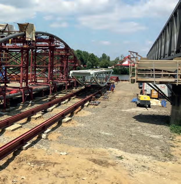
93 szerelőterület organizációját – ennek megfelelően optimalizálva – át kellett rendezni. A feleslegessé vált sín pályákat elbontottuk, és a szerelőállványok áttelepítése is megtörtént, hogy a hídelemek összeállítását a beemelési hely közelében lehessen elvégezni.
A hídelemek összeállítását vasbeton teherelosztó lapokon megfelelő kiosztás szerint elhelyezett acélszerkezetű állványokon és szerelőbakokon végeztük.
A készre szerelt hídelemek szerelőtéri mozgatása a keresztpályán egyszerű WälzWagen görgőkkel, hossz irányban pedig speciálisan erre a célra tervezett kocsikkal történt az alsó sínpályán magas, az indítóállványon és a bárkákon pedig alacsony kivitellel. A magas kocsikba beépített és hidraulikusan összekötött sajtók segítségével folyamatosan lehetőség nyílt a sínpálya terheléseinek kontrollálására mozgatás közben is. A moz
A rácsos szerkezetű ívállványok kialakítása modulrendszerben valósult meg, hogy a kapcsolódó hidak (Eger-patak- és Szomorka-patak-híd) szerelésénél is alkalmazhatók legyenek.
94 The tension monitoring was carried out by the Depart ment of Bridges and Structures of the Faculty of Civil Engineering of the Budapest University of Technology and Economics on behalf of Hódút Kft. by placing strain gauge
Aftersensors.thetensioning
was completed, the removal of the intermediate assembly support frames resulted the element to become a freely supported beam, making the structure suitable for movement. After completion of the installation, COLOR HELP Kft. repaired the operational corrosion protection in the vicinity of the welding seams that were made on-site, and then they applied the topcoating of the entire surface.The ready assembled bridge elements were moved in the assembly area on the transverse track with simple WälzWagen roller carriages and longitudinally with trolleys specially designed to this purpose, with high de signs on the lower rail track and with low designs on the launcher scaffolding and on the barges. With the help of presses built in and hydraulically connected into the high trolleys, it was constantly possible to control the loads on the launching rail track even during move ment. The movement into the trolleys was done on WW roller carriages with side guides. The arch supports of the riverbed elements, accord ingly, could only be supported or suspended at their ends during the crane liftings. The floodplain elements were truss girders, so in ad dition to their ends, they could be loaded near the junc tions too. 2.4.2
In order to lift the elements, a LIEBHERR LTM 1200 –5.1 type mobile crane with a load capacity of 200 tonns had to be installed in advance on both of the TS40 type barges used, with which in order to reduce the boom ex tension it was necessary to stand as close to the pillars as Crpossible.anelifting from the side would have been an obvi ous solution, but then the position of floating on the wa ter would have become unstable due to the deviation of more than 2 m from the longitudinal axis of the barge. Therefore, the task had to be solved from the stern of the barge by directly standing close to the pillars, leav ing only a narrow area to place the launching rail track and the crane on the barge. The asymmetrical place ment also resulted in a longitudinal tilt of the barge body, so to compensate this, a counterweight formed of reinforced concrete slabs had to be piled up at the bow.
The truck cranes were embarked onto the barges from the assembly area through a temporarily established ac cess bridge, positioning the two barges with their sterns close to each other. The presence of the crane in the riv erbed perpendicular to the direction of flow formed a continuous 100 m long barrier. During the lifts, the barge deck alone would not have been able to withstand the stresses of the outrigger pads of the cranes, therefore, a pair of load-distrib uting beams was placed under the outriggers through hardwood pads, supported on the ribs of the ship. The outriggers of the crane also had to be tied down to the deck against overturning. As the floating posi tion of the barges was constantly changing during the operations and the mobile cranes could only work in a horizontal position, their leveling had to be constantly checked and adjusted if necessary with the hydraulics of the outriggers of the cranes. Nevertheless, lifting on the water was considered to be a rather dangerous opera tion for the cranes due to the constantly moving barge deck, which required careful preparation of the work. On the barge, the launching rail tracks were designed as a continuation of the longitudinal track of the as-
Equipment of the deck of the barges
III. CONSTRUCTION – HÓDÚT KFT. 2. Tisza bridge
45. kép: Tisza-híd – Mederelem szerelése / 45.: Assembly of Tisza bridge riverbed element 46. kép: Tisza-híd – Mederelem rúdfeszítése folyamatban / Picture 46.: Tisza bridge riverbed element rod tensioning in progress


teni, amelyekkel a gémkinyúlás csökkentése érdekében minél közelebb kellett a pillérekhez állni.
Picture
Kézenfekvő megoldás lett volna az oldalról való daruzás, de ekkor a bárkatengelyből való – 2 m-t meghaladó – kitérés miatt az úszáshelyzet instabillá vált volna. Ezért a tat felől kellett megoldani a feladatot a pillérekhez való közvetlen ráállással, ami által csak szűk terület maradt a bárkasínpálya és a daru elhelyezésére. Az aszimmetrikus elhelyezés a bárkatest hosszirányú dőlését is eredményezte, ezért ennek kiegyenlítésére a hajóorrnál vasbeton lap depóniákból képzett ellensúlyozást kellett alkalmazni.
III. KIVITELEZÉS – HÓDÚT KFT. 2. Tisza-híd
Az elembeemelésekhez az alkalmazott 2 darab TS40 típusú bárkára előzetesen egy-egy LIEBHERR LTM 1200 –5.1 típusú, 200 t teherbírású autódarut kellett feltelepí-
95 gatás a kocsikba oldalvezetéssel ellátott WW görgőkön történt. A mederelemek ívtartói, ennek megfelelően csak a végeiken voltak alátámaszthatók vagy függeszt hetők a darus emelések alkalmával. Az ártéri elemek rácsos tartók, így a végein kívül a csomópontok közelében is terhelhetők voltak. 2.4.2. A bárkafedélzetek berendezése
The tracks were installed with stacked HEB beams, support with a height adjusting to the level of the water and the draft of the barge, fastened together with grat ings, and using load distribution beams. 2.4.3. Moving the bridge elements onto the barges and lifting them into place
We tried to ensure free passage for those intending to pass by boat as it was possible, therefore, when only coastal movements were executed, one bridge opening always remained navigable with the requirement of gentleBeforenavigation.starting the operations, the barges involved in the floating had to be placed side by side in the port and then connect them to the rail tracks. During the move ment of the elements, as soon as the front of the bridge structure left the launcher scaffolding, the loading of the barges and thus their gradual descent also began, which later changed to a rise as the load decreased. Due to the asymmetrical loading and descenting of the barges, the launching rail track was twisted under the first trolley, and this effect had to be balanced hydraulically during the operation with the high trolley that was moving on the coastal rail track in order to avoid overloading of the whole track. Since the hydraulics installed in the rear trolleys after the lifting of the rear end of the bridge element onto the launcher scaffolding were omitted due to the height restrictions, the torsional readjustment had to be performed with the stopping of the movement from time to time and the rear bridge end had to be pressed and the height had to be fixed by shimming using spacers. When the first trolley reached the center of the outer barge, it had to be fixed there, and then the two barges had to be separated from each other by unscrewing the connected rail tracks. The outer barge then moved to gether with the bridge until the rear trolley also reached the middle of the other barge.
47. kép: 200 t teherbírású daruk beléptetése a TS40 bárkákra / Picture 47.: Entry of 200 t cranes onto the TS40 barges III. CONSTRUCTION – HÓDÚT KFT. 2. Tisza bridge
Synchronous floating of the two TS40 type barges was key to maintaining the soundness of the cargo, so an embargo in the whole width of the riverbed was ordered for the duration of the floatings and liftings. Prior to the work processes, A.1 type passing is prohibited signs were placed on both the road and rail bridges, and A.1 signs were placed on buoys 500 m far before and after the bridges on the river, thus, we signaled to the boat men of the river Tisza that they could not cross under the bridge by boat during the special work processes.
96 sembly area, perpendicular to the longitudinal axis of the barges, fixed to the launcher scaffolding on the shore with hinge. During the designing of the rail tracks, it had to be taken into account that the barges can only be loaded in their center line, and under load they not only sink, but also tilt in longitudinal direction, there fore, the track had to be provided with hinged joints that could follow all the deformations that occurred when the bridge elements were moved onto the barge.

Az autódaruk behajózása a szerelőtérről egy ideig lenesen létesített bejáróhídon át történt, a két bárkát egymásnak farral pozicionálva. A daru beléptetése a mederben a folyásirányra merőlegesen egy összefüggő, 100 m-es akadályt jelentett.

III. KIVITELEZÉS – HÓDÚT KFT. 2. Tisza-híd

lett volna alkalmas, ezért a talpalások alatt teherelosztó gerendapárt helyeztünk el, keményfa alátéteken keresztül a hajóbordákra letámasztva. A darutalpakat ezen kívül borulás ellen is le kellett kötni a fedélzethez. Mivel a műveletek során a bárkák úszáshelyzete folyamatosan változott és az autódaruk csak kivízszintezett helyzetben tudnak dolgozni, ezért azt folyamatosan ellenőrizni kellett, és szükség esetén után kellett állítani a darutalpak hidraulikáival. Mindazonáltal a vízen végzett beemelés a daruk szempontjából meglehetősen veszélyes műveletnek minősült a terhelésváltozásra folyamatosan mozgó bárkafedélzet következtében, ami gondos előkészítő munkát igényelt. A bárkasínpályákat a szerelőtéri hosszpálya folyta tásaként, a bárkák hossztengelyére merőlegesen, a parti indítóállványhoz csuklósan rögzítve alakítottuk ki. A sínpályák megtervezésekor figyelembe kellett venni, hogy a bárkák csak középvonalukban terhelhetők, valamint teher hatására nemcsak süllyednek, hanem hosszirányban billennek is, ezért a pályát olyan csuklós kapcsolatokkal kellett kialakítani, amelyek a hídelemek bemozgatásakor fellépő összes deformációt le tudják követni.Apályákat HEB gerendás, a vízálláshoz és a bárka merüléséhez igazodó magasságú máglyás alátámasztással, rácsokkal összerögzítve, teherelosztó gerendák alkalmazásával telepítettük. 2.4.3. Hídelemek mozgatása bárkákra és beemelés A két TS40 bárka szinkron úsztatása kulcsfontosságú volt a szállítmány épségének megőrzése kapcsán, ezért a beúsztatások és beemelések idejére teljes mederszélességben hajózási zárlatot rendeltünk el. A munkafolyamatokat megelőzően a közúti és vasúti hidakra kihelyeztük az áthaladni tilos A.1 jelzéseket, valamint a hidak 48. kép: Tisza-híd – TM1 és TM2 mederelem a szerelőtéren / Picture 48.: Tisza bridge TM1 and TM2 riverbed elements at the assembly site
97
A beemelések során a darutalpak alatt fellépő igénybevételek elviselésére a bárkafedélzet önmagában nem
Both floating and elements on the shore were lifted from the immediate vicinity of their final location by mobile cranes.
98
By unleashing the barges from the shore, the bridge element was completely movable on the water and the floating to the pillars could begin.
III. CONSTRUCTION – HÓDÚT KFT. 2. Tisza bridge
Phases of the lifting: – lifting up by crane, – floating with a barge to the pillar, – tilting the boom over the bridge axis, – lowering.
The right side floodplain element was lifted to its place by the working together on a TEREX – DEMAG AC100-4 crane with a load capacity of 100 tonns on the shore and a crane with 200 tonns load capacity that was mounted on one of the barges. The other barge was given only element delivery task in the operation.

The first riverbed element was placed by the lifting together of two 200 tonns load capacity cranes that were mounted on the barges.
49. kép: Tisza-híd indulásra készen / Picture 49.: Tisza bridge ready to go
fölött és alatt 500–500 méterrel is bójákra kihelyezett A.1 táblákkal jeleztük a tiszai hajósok számára, hogy a speciális munkafolyamatok ideje alatt nem tudnak hajóval áthaladni a híd alatt. A lehetőségekhez mérten igyekeztünk szabad áthaladást biztosítani a hajóval áthaladni szándékozóknak, ezért a part menti mozgatások során egy hídnyílás mindig közlekedhető maradt kíméleti hajózás előírása mellett.Aműveletek megkezdése előtt először az úsztatásban részt vevő bárkákat kellett a kikötőben egymás mellé beállítani, majd a sínpályákkal összekötni őket. Az elemmozgatások során, amint a hídszerkezet eleje elhagyta az indítóállványt, megkezdődött a bárkák terhelése és ezáltal fokozatos süllyedésük is, ami később 50. kép: Tisza-híd – Szélső nyílás szállítása a szerelőtérről a csárda melletti támaszhoz / Picture 50.: The transport of the side opening part of the Tisza Bridge from the assembly area to the support next to the tavern 51. kép: Tisza-híd – Első mederelem beúsztatása / Picture 51.: Floating of the first riverbed element of the Tisza bridge
III. KIVITELEZÉS – HÓDÚT KFT. 2. Tisza-híd


100 The desinging of mooring points and the installa tion of the anchors by HSP Kft. had special importance, which precisely ensured the stability of the moved bridge elements with a span of 70 m and the success of the construction phase throughout the movement pro cess. Stability during lifting was enhanced by auxiliary floating elements tightly attached to the barges. The second riverbed element was lifted by a pair of 200 tonns cranes mounted on a barge and another 200 tonns crane on the shore in pairs as described above. The other crane that was on the other barge and had become redundant in the meantime was used as the shore crane. Synchronous floatings and near-pillar maneuvers on the water were done quickly and accurately thanks to the well-assembled team. The bridge elements above land were lifted by a pair of cranes.Aftercompleting the work, one is happy to look back at the graceful consoles and structures that were made 52. kép: Tisza-híd – Első mederelem beúsztatása / Picture 52.: Floating of the second riverbed element of the Tisza bridge III. CONSTRUCTION – HÓDÚT KFT. 2. Tisza bridge

101 a terhelés csökkenésével emelkedésbe váltott át. Mivel a bárkák aszimmetrikus terhelése és süllyedése miatt az első kocsi alatt a sínpálya csavarodott, ezt a hatást a parti sínpályán mozgó magas kocsival hidraulikus módon, menet közben le kellett követni a pálya túlterhelésének elkerülése érdekében. A hátsó hídvég indítóállványra történő felléptetése után a hátsó kocsikba beépített hidraulikák a magassági korlátok miatt elmaradtak, ezért a csavarodási utánállítást a mozgatással időnként megállva és a hátsó hídvéget sajtóra véve kellett elvégezni a magasság beilagolással történt rögzítésével.Amikor az első kocsi beért a külső bárka közepére, ott rögzíteni kellett, majd az összekötő sínpálya szétcsavarozásával a két bárkát egymástól el kellett oldani. A külső bárka ezután együtt mozgott a híddal, addig, ameddig a hátsó kocsi is a másik bárka közepéig nem ért.A bárka parttól való eloldásával a hídelem teljes egészében a vízre került, és megkezdődhetett a pillérekhez való beúsztatás.
53. kép: Tisza-híd – Első mederelem beemelése / Picture 53.: Lifting of the second riverbed element of the Tisza bridge

III. KIVITELEZÉS – HÓDÚT KFT. 2. Tisza-híd
Mind az úsztatott, mind a parti elemek beemelése a végleges helyük közvetlen közeléből autódarukkal történt.A jobb ártéri elem egy TEREX – DEMAG AC100-4 típusú, 100 tonna teherbírású parti daru és az egyik bárkára telepített 200 tonnás daru párosemelésével került a helyére. A másik bárka a műveletben csak elemszállítási feladatot kapott.
102 at the cost of great difficulties. The area is uniquely lined with bridges designed and implemented in differ ent eras with the railway bridge, the road bridge and the new graceful bicycle bridge, which we hope will proper ly serve those who want to hike and relax. We hope that, when they are resting and stopping for a moment, the question will arise in them as to how the constructors solved this complex task at that time. 54. kép: Az elkészült Tisza-híd / Picture 54.: The completed Tisza bridge
III. CONSTRUCTION – HÓDÚT KFT. 2. Tisza bridge

III. KIVITELEZÉS – HÓDÚT KFT. 2. Tisza-híd 55. kép: Különböző korok hídszerkezetei / Picture 55.: Bridges from different ages

bírt a HSP Kft. által megtervezett kikötési pontok, horgonyok telepítése, melyek a teljes mozgatási folyamat során precízen biztosították a mozgatott 70 m fesztávú hídelemek stabilitását és a kivitelezési fázis sikerességét. Az emelés közbeni stabilitást a bárkák mellé szorosan rögzített segéduszályok növelték. A második mederelem beemelése az egyik bárkára telepített 200 tonnás daru és egy parti 200 tonnás daru párosemelésével zajlott a fent már ismertetett módon. Parti daruként az időközben feleslegessé vált másik bárkás darut alkalmaztuk. A szinkronúsztatások és pillérközeli vízi manőverek az összeszokott csapatnak köszönhetően gyorsan, precízen történtek. A szárazföld feletti hídelemeket páros darus emeléssel emeltük fel. A munkák végeztével örömmel néz vissza az ember a nagy nehézségek árán elkészült kecses konzolokra, felszerkezetre. A terület egyedülállóan sorakoztat fel különböző korszakokban tervezett, megvalósított áthidalásokat a vasúti híddal, a közúti híddal és az új kecses kerékpároshíddal, mely reméljük, megfelelően szolgálja majd a túrázni és kikapcsolódni vágyókat. Reméljük, hogy megpihenve, megállva egy pillanatra majd bennük is felmerül a kérdés, hogy annak idején a kivitelezők hogyan is oldották meg ezt az összetett feladatot.
103 Az első mederelem a bárkákon lévő két 200 tonnás daru párosemelésével került a helyére.
A beemelés fázisai: – felemelés daruval, – ráúszás bárkával pillérig, – gémdöntés hídtengely fölé, – leeresztés.Kiemeltfontossággal
THE OPENABLE BRIDGE OF THE CHANNELFLUSHINGNO.X.
Picture 56.: Factory trial assembly of the bridge of the flushing channel No. X. 57. kép: X. sz. öblítőhíd – Helyszíni telepítése
Picture 57.: On site installation of the bridge of the flushing channel No. X. III. CONSTRUCTION – HÓDÚT KFT. 3. The openable bridge of the flushing channel No. X.

104 3
In the section between Poroszló and Tiszafüred, the smallest and most unique bridge is the bridge of the flushing channel No. X. with its 5.5 m free opening and openable design. The structure with a total weight of 8 tonns was realized on behalf of Hódút Kft., in the production of Weinberg ’93 Kft. and on-site installation of DLW 91 Kft.. During the production, only with extremely precise control could ensure the oiled cooperation of the me chanical elements and the structural steel elements. During the manufacturing process, several trial as semblies were performed under operating conditions where the operation of the mechanical parts were tested. The counterweight designed in the rear curved part of the boom played a big role, and the structure could be fine-tuned by manufacturing that curve from a steel sheet.The corrosion protection was performed in the fac tory by COLOR HELP Kft. on the structure, which was delivered to the site in a disassembled state after the coating had dried. The installation was quick and trou ble-free thanks to the factory trial installations. 56. kép: X. öblítőhíd – Üzemi próbaszerelés /

105 3 X. SZ.
58. kép: A megvalósult X. sz. öblítőhíd felnyitás közben / Picture 58.: The realized flushing channel bridge during opening III. KIVITELEZÉS – HÓDÚT KFT. 3. X.
A Poroszló Tiszafüred közötti szakaszon a legkisebb és legegyedibb híd a X. sz. öblítőcsatorna hídja a maga 5,5 m szabad nyílásával és nyitható kialakításával. A Hódút Kft. megbízásából a Weinberg ’93 Kft. gyártásában és a DLW 91 Kft. helyszíni szerelésével valósult meg a 8 t össztömegű szerkezet. A gyártás során rendkívül precíz ellenőrzéssel lehetett csak a gépészeti elemek és szerkezeti acél elemek olajozott együttműködését biztosítani. A gyártási folyamat során több alkalommal végeztek próbaszerelést üzemi körülmények között, ahol a gépészet működését tesztelték. Nagy szerepet kapott a gém hátsó ívébe tervezett ellensúly, melyet acéllemezből kialakítva sikerült a szerkezetet finomhangolni. A korrózióvédelmet üzemi körülmények között a COLOR HELP Kft. végezte a szerkezeten, melyet a bevonat száradását követően szétszerelt állapotban szállítottuk ki a helyszínre. A telepítés, a gyári próbaszereléseknek köszönhetően, gyorsan és problémamentesen zajlott. sz.

öblítőcsatorna nyitható hídja
NYITHATÓÖBLÍTŐCSATORNAHÍDJA
Test loading
III.
As a result of the existing conditions, the dynamic test loading was carried out by Hódút Kft. with its own employees, which is a recall of an old tradition in the bridge construction industry. It was a unique event for decades.Thedynamic test loading was performed with the participation of 56 colleagues divided to several groups of different sizes and speeds. Keeping the group shape and step frequency was key during the arranged pass ings through the bridge. The aim of the strategy and planned sequence of the test rounds was to determine the excitation frequencies relevant to the structures. For this, the loadings of the three bridges were held on one day, according to the same program. 28 test rounds were planned per bridge, which meant 12–16 passes on each bridge for the peo ple in the groups (by walking/running with a walking/ running distance of 90–150 m).

During the test rounds, accelerometers were placed on the bridge to determine the vertical and horizontal acceleration values of the structure, and 3–4 person at different points on the bridge evaluated the dynamic be havior of the bridge in terms of comfort.
59. kép: Szomorka-patak-híd – Dinamikus próbaterhelés a Hódút Kft. kollégáinak közreműködésével / Picture 59.: Szomorka creek bridge dynamic test loading with the participation of the colleagues of Hódút Kft. Construction – HÓDÚT KFT. 4.
The measurements required during the dynamic and static test loadings and the evaluation of the measure ment results were performed by the Faculty of Civil En gineering, Bridges and Structures of the Budapest Uni versity of Technology and Economics.
106 4
TEST LOADING 4.1. Dynamic test loading
4.1.
Eger
III. KIVITELEZÉS – HÓDÚT KFT. 4. Próbaterhelés
A fennálló körülmények folyományaként a dinamikus próbaterhelés kivitelezése a Hódút Kft. saját létszámával történt – mely egy régi hagyomány felidézése a hídépítés szakmában –, évtizedekre visszatekintve is egyedülálló esemény volt. A dinamikus próbaterhelést 56 fő kolléga részvételével hajtottuk végre, több különböző nagyságú és különböző sebességgel haladó csoporttal. A hídon való rendezett áthaladás során kulcsfontosságú volt a csoport alakzat- és lépésfrekvencia-tartása. A futamok stratégiájának és tervezett sorrendjének célja a szerkezetekre mértékadó gerjesztő frekvenciák meghatározása volt. Ennek érdekében a három híd terhelését egy nap alatt végeztük el, azonos program szerint. Hidanként 28 futam volt tervezve, mely a csoportokban részt vevő személyek számára 12–16 áthaladást jelentett mindegyik hídon (sétálva/futva, 90–150 m-es sétálási/futási távolsággal).
60.
/ Picture 60.: Dynamic
/ Picture 61.:
61. kép: Szomorka-patak-híd – Dinamikus próbaterhelés felülnézetből Dynamic test loading of Szomorka creek bridge from top view kép: próbaterhelés test loading of creek bridge
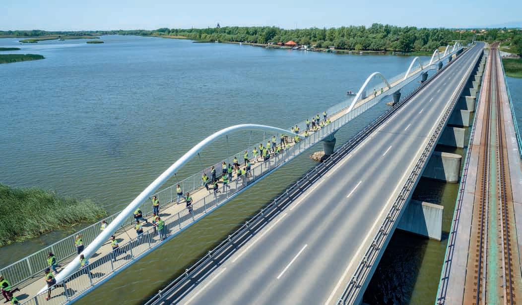

4
Eger-patak-híd – Dinamikus
PRÓBATERHELÉS
Dinamikus próbaterhelés
to the subjective comfort evaluators, only slightly or moderately disturbing vibrations were gen erated during the passing of the dynamically significant rounds. 62. kép: A Hódút Kft. próbaterhelő csapata / Picture 62.: Test loading team of Hódút Kft.
108 During the test loading, 28 load cases resulted from the combination of test rounds with different speeds and numbers of participants, which were as follows: – 2 persons, – 10 persons, – 26 persons, – 56 persons – slow walk at 3–4 km/h; – walk at 5–6 km/h; – jog at 8–9 km/h; – run at 10–15 km/h. For the most part in the dynamic test rounds, the group passed through the structures stepping in spec ified order, following a command, but there were also disordered, uncoordinated step rounds. In addition, there were two of the rounds, when a group of 10 people after jogging or running suddenly stopped in the middle of the Accordingbridge.
III. Construction – HÓDÚT KFT. 4. Test loading

A vizestartályok darabszáma úgy lett meghatározva, hogy a próbaterhelés során elérjük a tervezési teherszint min. 80%-át. A szerkezeteket 6–9. különböző teherállásban terheltük, és minden teherállásban szintezéssel mértük a hídszerkezetek alakját (lehajlását) felsőrendű szintezőműszerekkel, ±0,5 mm pontossággal. A próbaterhelés során mindegyik hídszerkezet esetén vizsgáltunk a hosszirányú parciális terhelést, totális terhelést, féloldalas és csavaró jellegű terhelést is. 63. kép: Szomorka-patak-híd – Statikus próbaterhelés / Picture 63.: Static test loading of Szomorka creek bridge III.
109 A dinamikus és statikus próbaterhelések során szükséges méréseket és a mérési eredmények kiértékelését a Budapesti Műszaki és Gazdaságtudományi Egyetem Építőmérnöki Kar, Hidak és Szerkezetek Tanszék vé gezte.Afutamok során a hídon gyorsulásmérőket helyeztünk el a futamok során a szerkezet függőleges és vízszintes gyorsulásértékeinek meghatározására, illetve a híd különböző pontján 3–4 fő komfortérzet szempontjából értékelte a híd dinamikai viselkedését. A próbaterhelés során a különböző sebességű, létszámú futamok kombinálásából adódott a 28 darab terhelési eset, melyek a következők voltak: – 2 fő, – 10 fő, – 26 fő, – 56 fő, – lassú séta 3–4 km/h, – gyaloglás 5–6 km/h, – kocogás 8–9 km/h, – futás 10–15 km/h.
A szubjektív komfortértékelők megítélése alapján a dinamikai szempontból mértékadó futamok áthaladása során is csak kismértékben, illetve mérsékelt módon zavaró rezgések keletkeztek a szerkezeten.

4.2. Statikus próbaterhelés
A statikus próbaterhelést mindhárom híd esetén vízzel feltöltött IBC tartályokkal végeztük el. Az alkalmazott –tartályszámok:Szomorka-patak hídja: 116 darab, – Eger-patak hídja: 128 darab, – Tisza-híd: 100 darab.
KIVITELEZÉS – HÓDÚT KFT. 4. Próbaterhelés
A dinamikus futamok nagy részében a csoport rendezett lépésben, vezényszóra lépve haladt át a szerkezeteken, de voltak rendezetlen, nem összehangolt lépéses futamok is. Ezenkívül a futamok között volt két olyan is, amikor egy-egy 10 fős csoport kocogás, illetve futás után a híd közepén hirtelen megállt.
Static test loading was performed with IBC tanks filled with water in case of all three bridges. Tank numbers –used:Szomorka creek bridge: 116 pcs, – Eger creek bridge: 128 pcs, – Tisza bridge: 100 pcs.

The result of the static test loading confirmed the planned behavior of the bridge structures taking into account the special structural behavior of the pendulum column joints and the adequate load-bearing capacity of the structures. The measurement results confirmed that the bridge structure meets the relevant require ments of the Highway Design Specification Require ments 2-2.208-2004 and can be placed into the traffic.
III. Construction – HÓDÚT KFT. 4. Test loading
110 4.2.
The number of water tanks was determined so that the the test loading could reach minimum 80% of the design load level. The structures were loaded in 6 to 9 different loading positions, and the shape (static deflection) of the bridge structures was measured by leveling in each loading position with accurate leveling instru ments, with an accuracy of ±0.5 mm. During the test loading, longitudinal partial loads, total loads, one-sid ed and torsional loads were also examined for each bridge structure.
Static test loading
64. kép: Eger-patak-híd – Statikus próbaterhelés / Picture 64.: Static test loading of Eger creek bridge
111 A statikus próbaterhelés eredménye igazolta a hídszerkezetek terv szerint viselkedését az ingaoszlopos lekötések speciális szerkezeti viselkedésének figyelembevételével és a szerkezetek kellő teherbírását. A mérési eredmények igazolták, hogy a hídszerkezet kielégíti az ÚT 2-2.208-2004 Útügyi Műszaki Előírás vonatkozó előírásait és forgalomba helyezhető. 65. kép: Szomorka-patak-híd – Statikus próbaterhelés / Picture 65.: Static test loading of Szomorka creek bridge III. KIVITELEZÉS – HÓDÚT KFT. 4. Próbaterhelés

THE REALIZED BRIDGES 1 EGER CREEK BRIDGE IV IV. THE REALIZED BRIDGES 1. Eger creek bridge

IV 1 EGER-PATAK HÍDJA
HIDAK IV. A MEGVALÓSULT HIDAK 1. Eger-patak hídja
MEGVALÓSULT

114 IV. THE REALIZED BRIDGES 1. Eger creek bridge

IV. A MEGVALÓSULT HIDAK 1. Eger-patak hídja

IV. THE REALIZED BRIDGES 1. Eger creek bridge

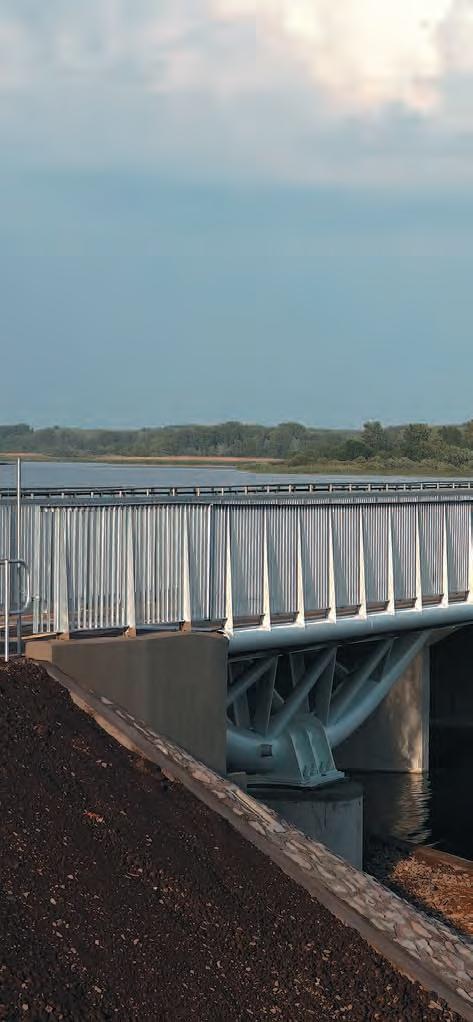
117 IV. A MEGVALÓSULT HIDAK 1. Eger-patak hídja

118 IV. THE REALIZED BRIDGES 1. Eger creek bridge


119 IV. A MEGVALÓSULT HIDAK 1. Eger-patak hídja

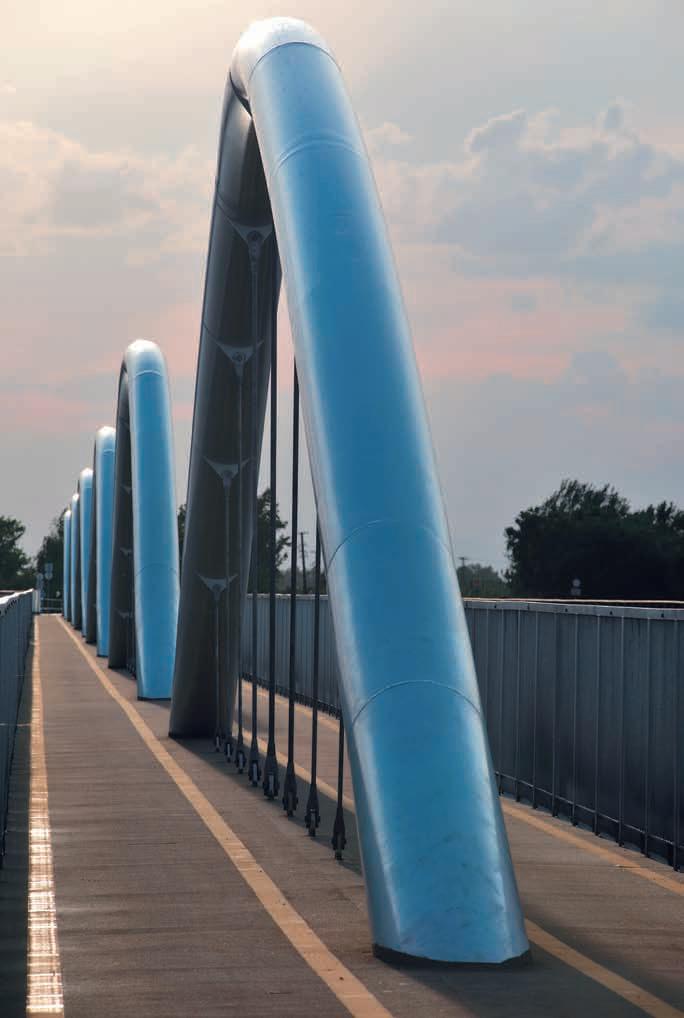

IV. THE REALIZED BRIDGES 1. Eger creek bridge

IV. A MEGVALÓSULT HIDAK 1. Eger-patak hídja

122 IV. THE REALIZED BRIDGES 1. Eger creek bridge


123 IV. A MEGVALÓSULT HIDAK 1. Eger-patak hídja


IV. THE REALIZED BRIDGES 1. Eger creek bridge


IV. A MEGVALÓSULT HIDAK 1. Eger-patak hídja


126 IV. THE REALIZED BRIDGES 1. Eger creek bridge

127 IV. A MEGVALÓSULT HIDAK 1. Eger-patak hídja


128 2 SZOMORKA CREEK BRIDGE IV. THE REALIZED BRIDGES 2. Szomorka creek bridge

2 SZOMORKA-PATAK HÍDJA IV. MEGVALÓSULT HIDAK 2. Szomorka-patak hídja

IV. THE REALIZED BRIDGES 2. Szomorka creek bridge

IV. MEGVALÓSULT HIDAK 2. Szomorka-patak hídja

132 IV. THE REALIZED BRIDGES 2. Szomorka creek bridge

133 IV. MEGVALÓSULT HIDAK 2. Szomorka-patak hídja


3 TISZA BRIDGE IV. THE REALIZED BRIDGES 3. Tisza bridge


3 TISZA-HÍD IV. MEGVALÓSULT HIDAK 3. Tisza-híd


136 IV. THE REALIZED BRIDGES 3. Tisza bridge

137 IV. MEGVALÓSULT HIDAK 3. Tisza-híd

138 IV. THE REALIZED BRIDGES 3. Tisza bridge

139 IV. MEGVALÓSULT HIDAK 3. Tisza-híd


140 IV. THE REALIZED BRIDGES 3. Tisza bridge
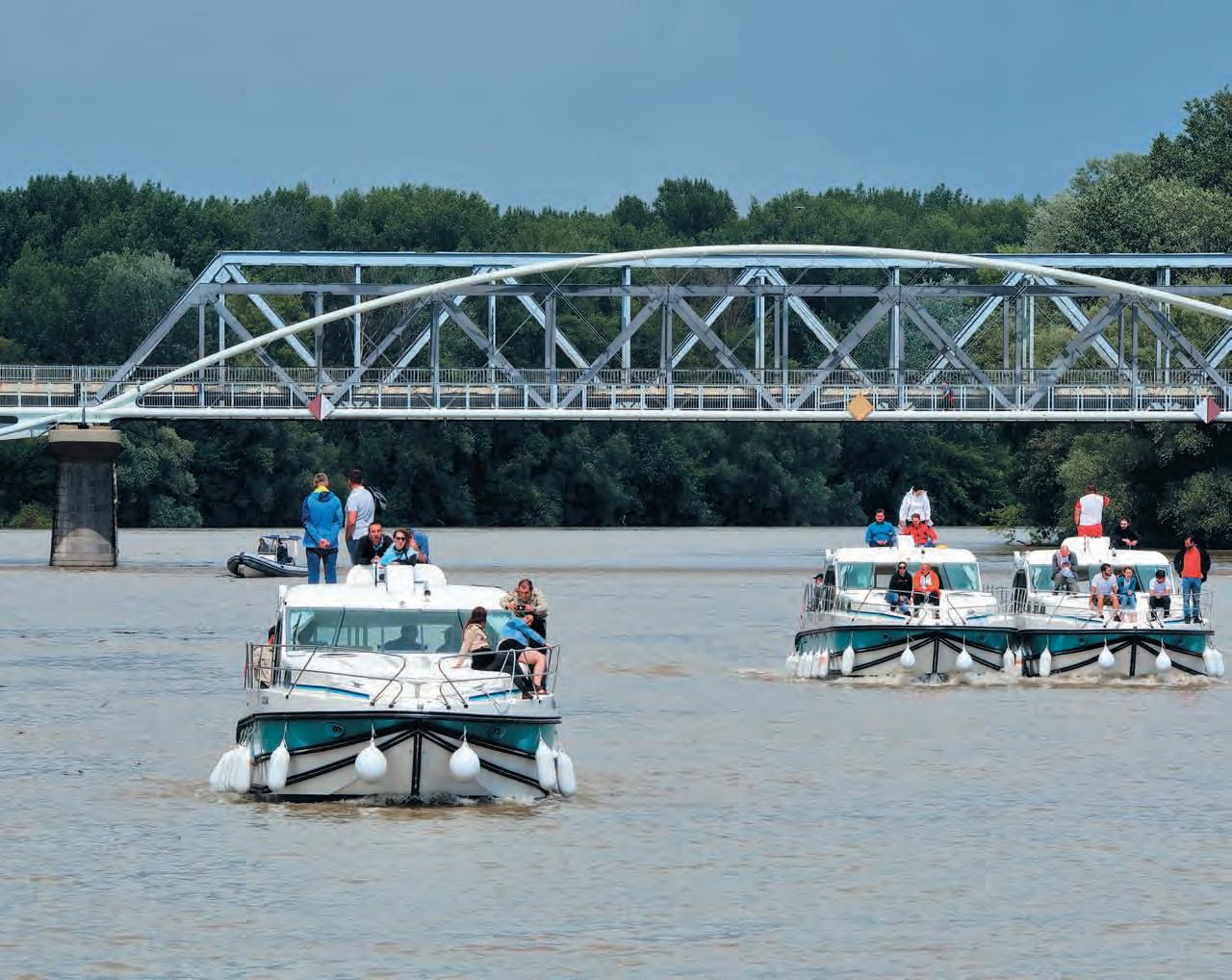
141 IV. MEGVALÓSULT HIDAK 3. Tisza-híd


IV. THE REALIZED BRIDGES 3. Tisza bridge

IV. MEGVALÓSULT HIDAK 3. Tisza-híd

144 IV. THE REALIZED BRIDGES 3. Tisza bridge

145 IV. MEGVALÓSULT HIDAK 3. Tisza-híd
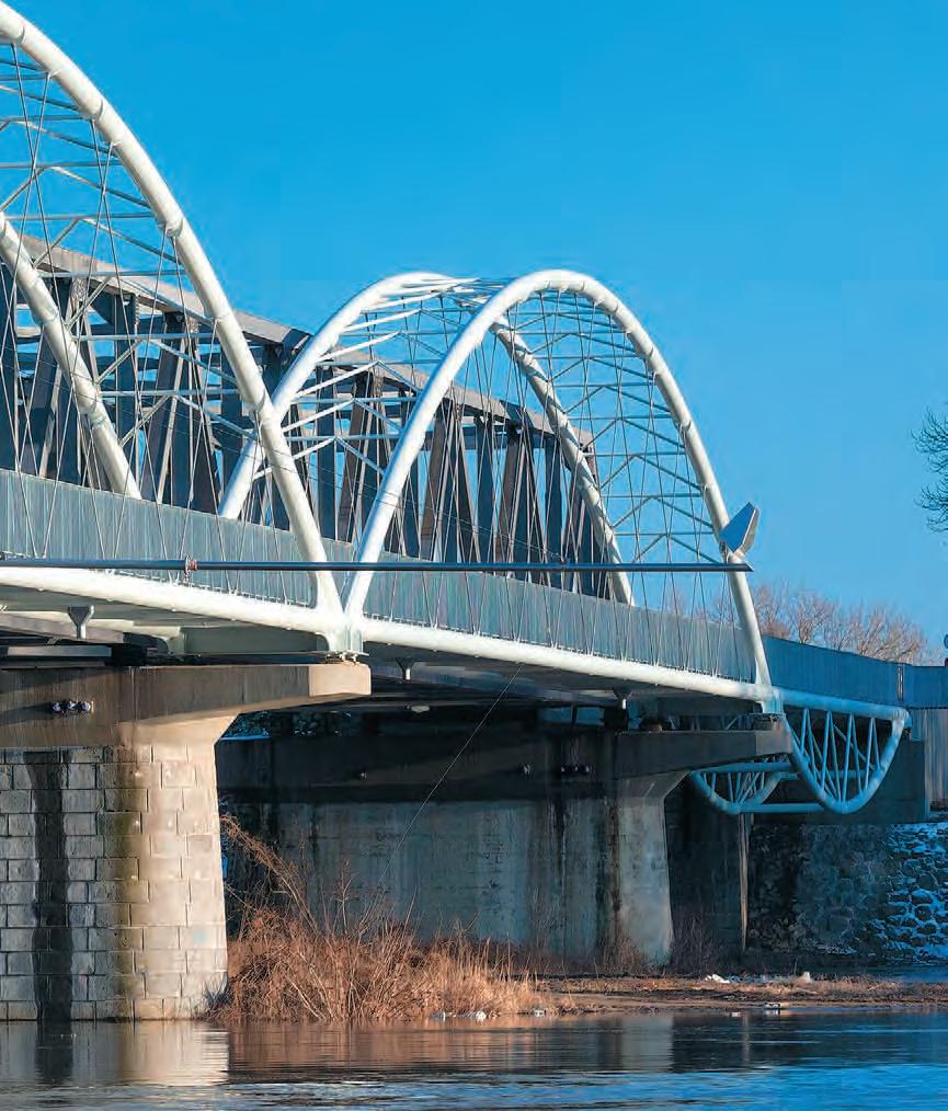

4 OPENABLE BRIDGE OF THE FLUSHING CHANNEL NO. X. IV. THE REALIZED BRIDGES 4. Openable bridge of the flushing channel No. X.

4 X. SZ. NYITHATÓÖBLÍTŐCSATORNAHÍDJA IV. MEGVALÓSULT HIDAK 4. X. sz. öblítőcsatorna nyitható hídja

148 IV. THE REALIZED BRIDGES 4. Openable bridge of the flushing channel No. X.
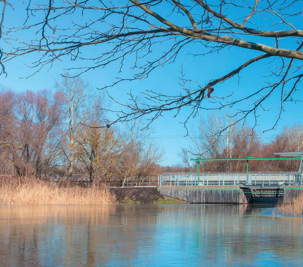
149 IV. MEGVALÓSULT HIDAK 4. X. sz. öblítőcsatorna nyitható hídja

150 IV. THE REALIZED BRIDGES 4. Openable bridge of the flushing channel No. X.


IV. MEGVALÓSULT HIDAK 4. X. sz. öblítőcsatorna nyitható hídja
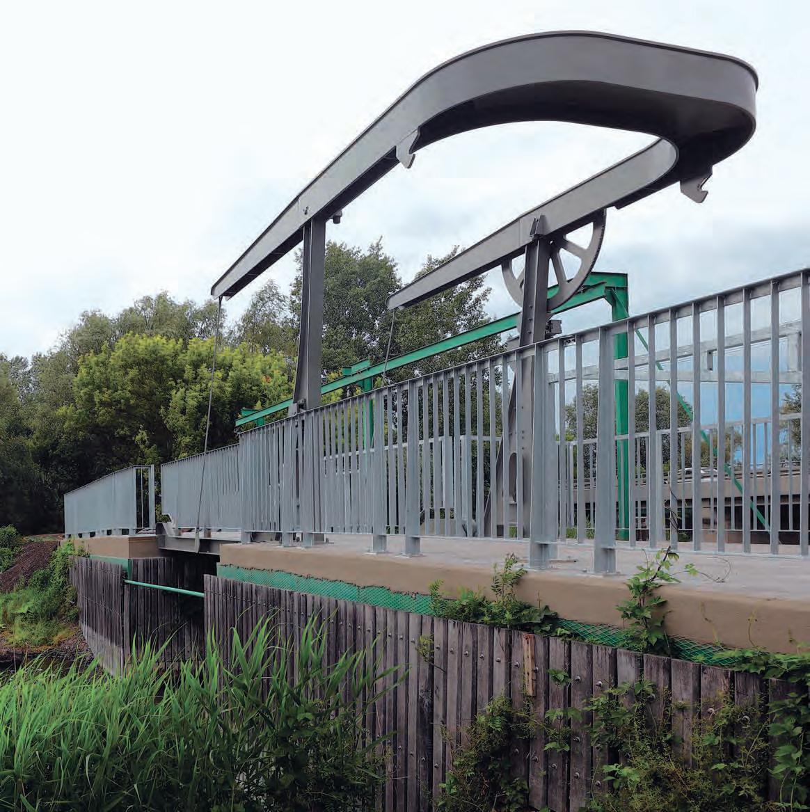
152 IV. THE REALIZED BRIDGES 4. Openable bridge of the flushing channel No. X.


153 IV. MEGVALÓSULT HIDAK 4. X. sz. öblítőcsatorna nyitható hídja


CLOSING REMARKS
66. kép: Eger-patak hídja a tavasz kezdetekor / Picture 66.: Bridge Eger creek at the start of spring V. CLOSING REMARKS V
The shape of the bridges on Lake Tisza, reinforced with continuous arches, is unique even internationally, the construction of the 308 m long superstructure with nine openings was possible to make by individual static decisions and detailed solutions that provide space for thermal movement. Methods that were used to analyze the behavior of the bridge: consideration of flexible soil embedding and the partially rigid fixing of the super structure-substructure and the static investigation of substructure-subsoil interaction through multiple soil parameters – have evolved over the last decade, so it can be said that an innovative new bridge has been built. New steel bridges constructed on the widening of the pier cap over the river Tisza enabled economical and aesthetic cycle path passage, which required remarka bly clever construction work to lift the large elements to their places from the water. The bridge structure of the flushing channel No. X. is Hungary’s first openable bicycle bridge.

ZÁRSZÓ V. ZÁRSZÓ V
A Tisza-tavi folytatólagos ívekkel merevített hidak formája nemzetközi szinten is egyedülálló. A kilenc nyílású, 308 m hosszú felszerkezet létesítését a hőmozgásnak teret adó egyedi statikai döntések és részletmegoldások tették lehetővé. A híd viselkedésének az analíziséhez használt módszerek, a talaj rugalmas ágyazásának figyelembevétele és a felszerkezet–alépítmény részlegesen merev befogása és az alépítmény–altalaj iterakció több talajparaméterrel való statikai vizsgálata – az elmúlt évtizedben fejlődtek ki, így mondhatni, hogy innovatív új híd épült. A Tisza folyó feletti fejgerenda-szélesítésen épülő új acélhidak gazdaságos és esztétikus kerékpárút átvezetést tettek lehetővé, melyek megépítéséhez a nagyméretű elemek vízről beemeléséhez bravúros kivitelezői munkára volt szükség. A X. sz. öblítőcsatorna műtárgya Magyarország első nyitható kerékpároshídja.

156 A megvalósítás során közreműködő szervezetek / Organizations participated in the implementation V. CLOSING REMARKS Organizations participated in the implementation
NIF Nemzeti Infrastruktúra Fejlesztő Zrt. Beruházó / Investor ÉPÍTŐMÉRNÖKI KFT. Speciálterv Kft. Híd- és műtárgy tervező – Tanulmány, engedélyezési és kiviteli tervek, továbbá a Kivitelezési fázisban út- és generáltervező / Bridge and structure designer – Study plans, permitting plans and implementation plans, and a road and general planner in the construction phase Hódút Kft. Generálkivitelező és acélszerkezeti generálkivitelező / General contractor and steel structure general contractor
157 PHOTOS AND FIGURES KÉPEK ÉS ÁBRÁK KÉPEK ÉS ÁBRÁK / PHOTOS AND FIGURES Képek / Photos 1–2. Bernáth Benjámin 3–5. Gyukics Péter 6. Speciálterv Kft. 7. Gyukics Péter 8–9. Szabó Zoltán 10. Litkey Csaba 11. Gajdos Gergely 12. Ábrahám Norbert 13. Speciálterv Kft. 14. Dernovics Tamás 15. Szabó Zoltán 16. Ábrahám Norbert 17. Vincent Van Gogh festmény reprodukciója 18. Szabó Zoltán 19–32. Hódút Kft. 33. Dernovics Tamás 34. Szabó Zoltán 35–46. Hódút Kft. 47. Speciálterv Kft. 48–54. Hódút Kft. 55. Szabó Zoltán 56–58. Hódút Kft. 59–62. Dernovics Tamás 63–65. Hódút Kft. 66. Szabó Zoltán IV. fejezet képei: Gyukics Péter, Szabó Zoltán és Dernovics Tamás Ábrák / Figures 1–2. Speciálterv Kft. 3. Pál Gábor 4–6. Speciálterv Kft. 7–8. Ábrahám Norbert 9–19. Speciálterv Kft. 20–27. Dési Attila 28–33. Speciálterv Kft. 34–37. Dési Attila 38–39. Speciálterv Kft. 40–41. Fonyódi Emil 42. Speciálterv Kft.
Picture 41.: Trial assembly of Tisza bridge floodplain element upside down ................... 88
158 LIST OF PHOTOS
LIST OF PHOTOS
Picture 42.: Trial installation of Tisza bridge riverbed element ............................... 89
......................................
Picture 43.: Tisza bridge elements are ready to go ..... 89
................................
................................
Picture 16.: Tisza-bridge – Construction visual design 55 Picture 17.: Vincent Van Gogh – The Langlois Bridge at Arles (1888) ..... 62
Picture 32.: Eger creek bridge arch girder installation 80 Picture 33.: Szomorka creek bridge structure over the water ......................... 82
Picture
Picture 27.: Trial assembly of the P1-P11 elements of Eger creek bridge .................... 77
Picture 30.: The arrival of the T2 element of the Szomorka creek bridge .................. 80
Picture 39.: Tisza bridge finished pier cap ............ 86
Picture 47.: Entry of 200 t cranes onto the TS40 barges ................................. 96
Picture 12.: The bridges of Eger and Szomorka creeks – Small Boat Harbor (has not been implemented) ............. 25
Picture
Picture 14.: Eger creek – Dynamic load test .......... 46
Picture 15.: F illed main pipe and lattice with increased cross sections .......................... 47
Picture 18.: Flushing structure No. X. – State after installation ................ 63 Picture 19.: Pillar reinforcement and the reinforced concrete structure 73 Picture 20.: Arch supporting element of the Eger creek bridge under the resting place ........... 73
Picture 26.: Elements to be concreted to receive the “Sauseage-filler” .................... 77
Picture 11.: Eger creek bridge – Visual design study ... 25
Picture
Picture 44.: Tisza bridge assembly area .............. 92
Picture 37.: Carving of the Tisza bridge pier cap ...... 85
Picture 25.: Trial assembly of Szomorka creek bridge deck .................................. 76
Picture 34.: Resting place on Szomorka creek bridge .. 82 Picture 35.: Eger creek bridge ....................... 83
Picture 28.: Szomorka creek bridge under construction 78 Picture 29.: The lifting of T2 bridge element of Szomorka creek bridge ........................... 78
Picture 8.: Departure from Poroszló ................ 18 9.: Arrival in Tiszafüred ................... 19 Picture 10.: Openable bridge structure ............... 24
Picture 22.: The bent pipe main girders of Eger creek and Szomorka creek bridges.............. 75 Picture 23.: New 3D plasma cutting machine at work . 75
................................
Picture 31.: Szomorka creek bridge access road embankment and assembly site .......... 80
Picture
Picture 21.: Bending of the main girder pipes of the Eger creek and Szomorka creek bridge ... 74
Picture
Picture 36.: Tisza bridge pier shear studs ............ 84
Picture 38.: Installation of the reinforcement of Tisza-bridge pier cap ................. 85
Picture 1.: View of Lake Tisza ...................... 6 2.: Crossing of road number 33 on Lake Tisza 7 3.: Birdlife 10 4.: Birdlife 11 5.: Birdlife 11 6: Beaver with hiding lifestyle .............. 13 7.: The water surface of Lake Tisza near Poroszló 14
Picture
Picture 45.: Assembly of Tisza bridge riverbed element 95 Picture 46.: Tisza bridge riverbed element rod tensioning in progress .................. 95
Picture 13.: Existing, operating Tisza bridges ......... 28
Picture 24.: The "Sausage-filler" support (Eger creek and Szomorka creek bridge supporting element) .................... 76
Picture 40.: Connection detail of pipe girders ......... 87
Picture
...............................
KÉPEK JEGYZÉKE
1. kép: A Tisza-tó látképe ......................... 6 2. kép: A 33. sz. főút keresztezése a Tisza-tavon ..... 7 3. kép: Madárvilág 10 4. kép: Madárvilág 11 5. kép: Madárvilág 11 6. kép: A rejtőzködő életmódú hód 13 7. kép: A Tisza-tó vízfelülete Poroszló mellett az elkészült Eger-híddal .................... 14 8. kép: Indulás Poroszlóról ....................... 18 9. kép: Érkezés Tiszafüredre ...................... 19 10. kép: Nyitható hídszerkezet 24 11. kép: Eger-patak-híd – Kivitelitervi látványterv 25 12. kép: Eger- és Szomorka-patak-hidak – Kishajókikötő (nem valósult meg) ......... 25 13. kép: Meglévő, üzemelő Tisza-hidak .............. 28 14. kép: Eger patak – Dinamikus terhelés ............ 46 15. kép: Kibetonozott csőtartó és növelt keresztmetszetű rácsrudak 47 16. kép: Tisza-híd – Kiviteli látványterv 55 17. kép: Vincent Van Gogh – The Langlois Bridge at Arles (1888) ........ 62 18. kép: X. sz. öblítőcsatorna műtárgya – Ráépítés utáni állapot .................... 63 19 kép: Pillér vasalása és kizsaluzott vasbeton szerkezete 73 20. kép: Eger-patak-híd pihenőhelye alatti pillér ...... 73 21. kép: Eger-patak- és Szomorka-patak-híd csőfőtartóinak hajlítása .................... 74 22. kép: Eger-patak- és Szomorka-patak-híd hajlított csőfőtartói 75 23. kép: Munkában az új 3D plazmavágó berendezés 75 24. kép: A „hurkatöltő” támasz (Eger-patakés Szomorka-patak-híd támaszelem) ......... 76 25. kép: Szomorka-patak-híd – pálya próbaszerelése .. 76 26. kép: Bebetonozandó elemek „hurkatöltő” fogadásához 77 27. kép: Eger-patak-híd P1-P11 elemek próbaszerelése 77 28. kép: Szomorka-patak-híd – Építés közben ........ 78 29. kép: Szomorka-patak-híd – T2 jelű elem beemelése 78 30. kép: Szomorka-patak-híd – T2 jelű elem érkezése . 80 31. kép: Szomorka-patak-híd–Betöltésésszerelőterület 80 32. kép: Eger-patak-híd – Ívtartó szerelése 80 33. kép: Szomorka-patak-híd szerkezete a víz felett ... 82 34. kép: Pihenőhely a Szomorka-patak-hídon ........ 82 35. kép: Eger-patak-híd 83 36. kép: Tisza-híd – Fejgerenda tüskézése ........... 84 37. kép: Tisza-híd – Fejgerenda visszavésése 85 38. kép: Tisza-híd – Fejgerenda vasszerelése 85 39. kép: Tisza-híd – Elkészült fejgerenda . . . . . . . . . . . . . 86 40. kép: Tisza-híd – Csőfőtartó csomópont ........... 87 41. kép: Tisza-híd – Ártéri elem próbaszerelése fejtetőre állítva ........................... 88 42. kép: Tisza-híd – Mederelem próbaszerelése 89 43. kép: Tisza-híd – Elem indulásra készen 89 44. kép: Tisza-híd – Szerelőtér 92 45. kép: Tisza-híd – Mederelem szerelése ............ 95 46. kép: Tisza-híd – Mederelem rúdfeszítése folyamatban .............................. 95 47. kép: 200 t teherbírású daruk beléptetése a TS40 bárkákra 96 48. kép: Tisza-híd – TM1 és TM2 mederelem a szerelőtéren ............................ 97 49. kép: Tisza-híd indulásra készen ................. 98 50. kép: Tisza-híd – Szélső nyílás szállítása a szerelőtérről a csárda melletti támaszhoz ... 99 51. kép: Tisza-híd – Első mederelem beúsztatása 99 52. kép: Tisza-híd – Első mederelem beúsztatása 100 53. kép: Tisza-híd – Első mederelem beemelése 101 54. kép: Az elkészült Tisza-híd ...................... 102 55. kép: Különböző korok hídszerkezetei ............ 103 56. kép: X. öblítőhíd – Üzemi próbaszerelés .......... 104
..............................
159
...............................
KÉPEK JEGYZÉKE
............................
..............
Picture 56.: Factory trial assembly of the bridge of the flushing channel No. X. ............ 104
......................
Picture 54.: The completed Tisza bridge 102
Picture 62.: Test loading team of Hódút Kft. .......... 108
Picture 63.: Static test loading of Szomorka creek bridge Static test loading of Eger creek bridge Static test loading of Szomorka creek bridge Bridge Eger creek
.........
Picture 60.: Dynamic test loading of Eger creek bridge 107 61.: Dynamic test loading of Szomorka creek bridge from top view 107
... 110 Picture 65.:
Picture
Picture 49.: Tisza bridge ready to go ................. 98
Picture 50.: The transport of the side opening part of the Tisza Bridge from the assembly area to the support next to the tavern 99
......................
Picture 53.: Lifting of the second riverbed element of the Tisza bridge 101
Picture 57.: On site installation of the bridge of the flushing channel No. X. ............ 104
................................. 109 Picture 64.:
at the start of spring 154 LIST OF PHOTOS
.................
......................
................................. 111 IV. THE REALIZED BRIDGES ........................ 112 1. EGER CREEK BRIDGE 112 2. SZOMORKA CREEK BRIDGE ................... . 128 3. TISZA BRIDGE ............................... 134 4. OPENABLE BRIDGE OF THE FLUSHING CHANNEL NO. X. ............................... 146 Picture 66.:
Picture 48.: Tisza bridge TM1 and TM2 riverbed elements at the assembly site 97
Picture
Picture 55.: Bridges from different ages ................ 103
Picture 59.: Szomorka creek bridge dynamic test loading with the participation of the colleagues of Hódút Kft. 106
Picture 58.: The realized flushing channel bridge during opening 105
........................
....................
Picture 51.: Floating of the first riverbed element of the Tisza bridge 99 52.: Floating of the second riverbed element of the Tisza bridge 100
160
161 57. kép: X. sz. öblítőhíd – Helyszíni telepítése 104 58. kép: A megvalósult X. sz. öblítőhíd felnyitás közben 105 59. kép: –Szomorka-patak-hídDinamikuspróbaterhelés a Hódút Kft. kollégáinak közreműködésével ............. 106 60. kép: Eger-patak-híd – Dinamikus próbaterhelés 107 61. kép: –Szomorka-patak-hídDinamikuspróbaterhelés felülnézetből ..... 107 62. kép: A Hódút Kft. próbaterhelő csapata .......... 108 63. kép: Szomorka-patak-híd – Statikus próbaterhelés . 109 64. kép: Eger-patak-híd – Statikus próbaterhelés 110 65. kép: Szomorka-patak-híd – Statikus próbaterhelés 111 IV. MEGVALÓSULT HIDAK .......................... 113 1. EGER-PATAK HÍDJA ........................... 113 2. SZOMORKA-PATAK HÍDJA ..................... 129 3. TISZA-HÍD 135 4. X. SZ. ÖBLÍTŐCSATORNA NYITHATÓ HÍDJA 147 66. kép: Eger-patak hídja a tavasz kezdetekor ........ 154 KÉPEK JEGYZÉKE
..................................
Figure 5.: Side view of the widened bridge – technical proposal 2005 ............... 26
Figure 29.: Tisza-bridge – A detail of the general plan 53
Figure 38.: Side view and top view of the openable bridge 67
Figure 23.: F inite element model of cross girders stiffened with flanges at the widening deck plate .................................. 44
Figure 6.: Proposed structure to the floodplain openings: 3D truss on the steel cantilever extension to be built on the substructure – technical proposal 2005 ............... 27
Figure 41.: Mechanical design detail of the bridge of the flushing channel No. X. ........... 68
Figure 36.: Tisza bridge – Tensioning phases 61
Figure 12.: Flushing channel bridge ................. 33
LIST OF FIGURES
Figure 33.: Tisza bridge – Construction plan detail of riverbed bridge part .................. 58
Figure 7.: Conceptual solution of Tisza bridge widening, virtual 3D “model” ............ 30 F igure 8.: Early, colored Sketch Design of Tisza Bridge, still with Vierendeel side openings ....... 30 F igure 9.: Eger creek bridge ....................... 32
Figure 24.: Tie and arc girder connection ........... 44
Figure 4.: Cantilever extension of the superstructure of the Tisza bridge in Tiszafüred – technical proposal 2005 ............... 26
Figure 28.: Tisza-bridge – General plan – side wiev .. 50
Figure 15.: Spatial model of contour reinforcement of pillars .............................. 39
Figure 17.: Suspension rods ........................ 40 F igure 18.: The cross section of the tie girder on the normal and widened section ...... 40 F igure 19.: The cross section of the upper deck bridge section ................................ 41 F igure 20.: The finite element model of the tie down of the unidirectionally moving pipe girder 43
Figure 13.: The side view and longitudinal section of Eger creek bridge .................... 34
F igure 3.: The bridges of Eger and Szomorka creeks – Support concept sketch ................ 24
F igure 26.: The finite element model of Szomorka creek bridge ................................. 45
Picture 22.: F inite element model – Eger creek bridge .. 44
Figure 14.: The side view and longitudinal section of Szomorka creek bridge ................ 36
F igure 27. Eger creek – 1st vertical bending vibration 48
F igure 30.: Tisza bridge – Existing bridge pier cap reinfor cement and the cantilever overhang for the bicycle bridge .................... 54
.................................
F igure 32.: Tisza bridge – Tie girder rod connection 56
F igure 35.: Tisza bridge – F inite element model of the arc shoulder and end cross girder .. 60
Figure 34.: Tisza bridge – Self-frequency, shape 4. .... 59
Figure 39.: Detailed plan of the steel structure of the bridge – Deck plate cross section ... 68
Figure 21.: The finite element model of end cross girder and pendulum column supports .......... 43
Figure 25.: Tensioning the hangers by raising the tie girders .......................... 45
162
Figure 16. Reinforced concrete plan of pillar ........ 39
F igure 31.: Tisza bridge – Tie girder cross section .... 56
F igure 2.: Truss-girder version in the case of the the Eger creek – Study plan 2006 ... 21
Figure 1.: Beam girder version in the case of the the Eger creek – Study plan 2006 ... 20
Figure 42.: Eger creek bridge element distribution .... 76
LIST OF FIGURES
Figure 10.: Tisza bridge ........................... 32 Figure 11.: Szomorka creek bridge .................. 32
F igure 37.: Examination of the additional load on the foundation in a static program .... 64
Figure 40.: Static models in AxisVM ................ 68
163
1. ábra: Gerendatartós verzió az Eger-patak esetében – Tanulmányterv 2006 .................... 20
ÁBRAJEGYZÉK
2. ábra: Rácsos tartós verzió az Eger-patak esetében – Tanulmányterv 2006 .................... 21 3. ábra: Eger- és Szomorka-patak-hidak – Támaszkoncepció vázlata 24
4. ábra: A tiszafüredi Tisza-híd felszerkezetének konzolos bővítése – Műszaki javaslat 2005 ................... 26 5. ábra: A szélesített híd oldalnézete – Műszaki javaslat 2005 26 6. ábra.: Az ártéri nyílásokra javasolt szerkezet: térrács az alépítményre építendő acélkonzol –bővítményenMűszakijavaslat 2005 ................... 27 7. ábra: A Tisza-híd szélesítésének elvi megoldása – Virtuális 3D „makett” .................... 30 8. ábra: A Tisza-híd színezett korai vázlatterve, még Vierendeel szélső nyílásokkal – Oldalnézet – hosszmetszet ................ 30 9 ábra: Eger-patak hídja .......................... 32 10. ábra: Tisza-híd ................................. 32 11. ábra: Szomorka-patak hídja ..................... 32 12.: ábra: X. sz. öblítőcsatorna hídja 33 13. ábra: Eger-patak-híd–Oldalnézetés hosszmetszet 34 14. ábra: Szomorka-patak-híd–Oldalnézetéshosszmetszet ............... 36 15. ábra: A pillérek kontúrvasalásának térbeli modellje . 39 16. ábra: Pillér vasbeton terve ....................... 39 17. ábra: Függesztőrudak . . . . . . . . . . . . . . . . . . . . . . . . . . . 40 18. ábra: Merevítőtartó keresztmetszete normál és szélesített szakaszon .................... 40 19. ábra: Felsőpályás szakasz keresztmetszete ........ 41 20. ábra: Csőtartó egy irányban mozgó lekötése – Végeselemes modell ..................... 43 21. ábra: Végkereszttartó és ingaoszlopos támaszok – Végeselemes modell ..................... 43 22. ábra: Eger-patak-híd – Végeselemes modell ........ 44 23.ábra: Övlemezzel merevített kereszttartók végeselemes modellje a kiszélesedő pályalemezél 44 24. ábra: Merevítőtartó és ívtartó kapcsolata 44 25. ábra: Rudak feszítése a merevtőtartó megemelésével ........................... 45 26. ábra: –Szomorka-patak-hídVégeselemesmodell ..................... 45 27.: ábra: Eger-patak – 1. hajlítórezgés 48 28. ábra: Tisza-híd – Általános terv – oldalnézet 50 29. ábra: Tisza-híd – Általános terv részlet 53 30. ábra: Tisza-híd – Meglévő híd fejgerenda-erősítés és a kerékpároshídhoz a konzolos túlnyúlás .. 54 31. ábra: Tisza-híd – Merevítőtartó keresztmetszete ... 56 32. ábra: Tisza-híd – Merevítőtartó rúdbekötés ........ 56 33. ábra: Tisza-híd – Mederhídelem gyártmányterv részlet 58 34. ábra: Tisza-híd – Sajátfrekvencia 4. alak .......... 59 35. ábra: Tisza-híd – Ívváll és végkereszttartó, végeselem modell .......................... 60 36. ábra: Tisza-híd – Feszítési fázisok 61 37. ábra: Alapozásra jutó többletterhelés vizsgálata statikai programban ...................... 64 38. ábra: A nyitható híd oldalnézete és felülnézete ..... 67 39. ábra: A híd acélszerkezeti tervének részletterve – Pályalemez keresztmetszet ............... 68 40. ábra: AvisVM statikai modell 68 41. ábra: X. sz. öblítőcsatorna-híd – Gépészeti terv részlete 68 42. ábra: Eger-patak-híd – Elemosztás ................ 76
ÁBRAJEGYZÉK
164
EGER-PATAK-HÍD SZOMORKA-PATAK-HÍD X. ÖBLÍTŐCSATORNA NYITHATÓ HÍDJA TISZA FOLYÓ HÍDJA EGER BRIDGE SZOMORKA BRIDGE NR. X. BASCULE BRIDGE TISZA RIVER BRIDGE
