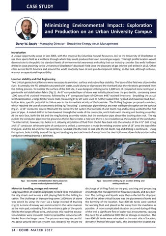
CASE STUDY Minimizing Environmental Impact: Exploration and Production on an Urban University Campus Darcy W. Spady - Managing Director - Broadview Energy Asset Management Introduction A unique opportunity arose in late 2003, with the proposal by Columbia Natural Resources, LLC to the University of Charleston to use their sports field as a wellbore through which they could produce their own natural gas supply. This high profile location would demonstrate to the public the standard levels of environmental awareness and safety that our industry consider. Gas wells had been drilled in close proximity to the University of Charleston’s Blackwell Field since the discovery of gas in brine well drilled in 1815. Other cities across North America and around the world routinely have oil and gas development drilling, so the task, although arduous, was not an operational impossibility. Location stability and Civil Engineering Two critical geotechnical factors were necessary to consider; surface and subsurface stability. The base of the field was close to the river. Essentially, the fill, probably saturated with water, could slump or slip toward the riverbank due the vibrations generated from the drilling process. To stabilize the surface of the drill site, it was designed utilizing some 1,600 tons of compacted stone resting on a geo-textile soil stabilization fabric (Fig.1). An 8” compacted layer of stone was initially placed over the geo-textile, containing some 1000 tons of #3 crushed limestone, followed by a 4” compacted layer of 600 tons #467 washed limestone. Straddling the actual wellhead location, 2 large timber crane mats measuring 8’ by 20’ were used to further support the rig load and maximize load distribution. Also, specific potential for failure was in the immediate vicinity of the borehole. The Drilling Engineer proposed a solution, which required the use of a concentric drilling rig “installing” a conductor pipe without any near wellbore disruption on the surface (Fig.2). A 16” conductor pipe is fitted with the concentric bit system that consists of a bit tooth ring and bushing welded to the first joint of pipe. A mated drill bit is then lowered through the inside of the conductor, and it locks with the ring and bushing assembly. At the rock face, both the bit and the ring/bushing assembly rotate, but the conductor pipe above the bushing does not. The rig pushes the conductor pipe into the ground as the bit face creates a hole and there is no circulation up the outside of the conductor. The internal bit, however, has holes in it, allowing circulation of fluid from the bit face back into the annulus of the 4 ½” drill string and 16” conductor. When one joint of conductor is drilled, a connection is made by welding another joint of 16” onto the top of the first joint, and the bit and internal assembly is run back into the hole to lock into the bit tooth ring and drilling is continued. Using this system, hole stability around the rig and sealing any encroachment of water from the river bottom or down hole erosion in the conductor setting process is achieved.
Fig.1 - Geo-textile soil stabilization fabric placed on access road and planned drill pad.
Materials handling, storage and removal Large quantities of location aggregate needed to be moved over the city streets and across a soft playing field to the drilling location. The challenge of transporting some 1,600 tons of stone was solved by using the river via a barge instead of trucking (Fig.3). A stone driveway was constructed in the same manner as the main pad, extending from the entrance gate of the sports field to the barge offload area, and across this road the excavator and dozer were moved in order to spread the stone once offloaded from the barge crane. The process was very successful. An above ground steel pit system was designed to ensure no
14 | E C H O • M A R C H 2017
Fig.2 - Concentric drilling rig on location drilling and setting conductor.
discharge of drilling fluids to the pad, catching and processing of cuttings, the management of flow back liquids, and dust control. The cuttings and liquids were then collected for disposal. One of the other critical factors was the placement of tanks and the berming of the location. Two 400 bbl tanks were spotted for working fluid and placed as far away from the riverbank as possible. A more complicated situation occurred during drilling of the well a significant flow of water was encountered, causing the need for an additional 2000 bbls of storage on location. The two 400 bbl tanks were relocated to the east side of location, directly in front of the pipe racks. This crowded the location sig-