Repair of Old Buildings Course


SPAB
2022 Handbook: Additional resources
Additional resources
The SPAB Approach

Need for old buildings to breathe Control of Damp
Energy Efficiency
Repair of Wood Windows


Patching Old Floorboards
Caring for Old Floors
Gypsum Plaster Floors
Slate and Stone Roofing in Wales and the Marches
Slating in the East Midlands
Slating in South-West England
Plumbing Leadwork:
Conservation
and
Charity number 1113753 Company number 5743962
Scottish charity number: SC 039244
Registered in Ireland: 20158736
Contents
Joints
Pipes
of Decorative Leadwork The SPAB 37 Spital Square London E1 6DY 0207 377 1644 education@spab.org.uk / info@spab.org.uk


b
SPAB William Morris Craft Fellow, Andrew Johnson
Picture: Ralph Hodgson
“
The Great British conservation movement ... draws its intellectual energy and passion from the wellspring that is the Society for the Protection of Ancient Buildings. ”
Ke vin Mc c loud, SPAB Me MB er, de S igner A nd T v P re S en T er.
Foreword
The SPAB is over 140 years old and is widely admired around the world as the fount of conservation thinking for the built heritage. It is still involved in the everyday problems and battles that old buildings face today.
One of the reasons for the Society’s longevity is its founding, not on commercial or political ground, but on a philosophy that offers proven and sustainable conservation ideas.
The principles contained in the elegant, precise prose of William Morris’s Manifesto have served to enlighten those who care for old buildings since the founding of the Society, but each generation has had to consider how those principles apply to the particular problems of the age.
The aim of this document, under the title the SPAB A PP ro A ch is to re-present and interpret the Manifesto for new audiences in the 21st century. It provides practical guidance for building owners and professionals who manage or need to repair an old building, while, for the Society, the Approach informs our strategic direction as well as providing a basis for much of our work including campaigning, training and advice.
At the same time, we seek to reach the widest possible audience, including our new members, writers, grant funders, peer organisations and the next generation of home owners, so that they can appreciate the singular and reasoned line of thought that helps us ‘protect our ancient buildings, and hand them down instructive and venerable to those that come after us’.
Iain Boyd, Chairman
a
St Mary Magdalene, Caldecote, Hertfordshire.
Picture: SPAB
THE SPAB APPROACH4


THE SPAB APPROACH6
b
Introduction
t he SPAB A PP ro A ch to building conservation combines well-proven principles with practical repair techniques. It has influenced building conservation worldwide and underpins much in UK heritage legislation. Other conservation approaches exist, but the Society’s principles are viewed by most as the yardstick.
t he SPAB A PP ro A ch began as an outcry against destructive work, but the guidance the Society offers today is practical and positive.
It aims to promote the value and good sense of caring for the fabric of old buildings. The SPAB takes a long-term view, urging that in our own actions we consider the legacy we will leave to future generations.
“ It is for all these buildings, therefore, of all times and styles, that we plead, and call upon those who have to deal with them, to put Protection in the place of Restoration. ”
q“ Stave off decay by daily care ” — from the SPAB Manifesto
Tile repair to the door of Rottingdean Church, Sussex, 1920s
Picture: SPAB
THE SPAB APPROACH 7
Historical background
The SPAB’s ideas stem from the thoughts of John Ruskin. In his ‘Seven Lamps of Architecture’ (published 1849) Ruskin railed against destructive work to old buildings, described at the time as ‘restoration’. Ruskin called restoration ‘a lie from beginning to end’ because it sought to change the character of an old building by erasing the evidence and record of its true history. The SPAB’s founders, led by writer and designer William Morris and architect Philip Webb, took up Ruskin’s ideas and translated them into the Society’s founding Manifesto. The Manifesto remains a concise and beautifully poetic expression of SPAB conservation principles, as relevant to the needs of today as to those of the 19th century. SPAB members have applied the Manifesto’s ideas to the care and repair of thousands of historic structures in the UK and beyond.
Early on, the SPAB was nick-named ‘Antiscrape’ as it rejected the 19th century fashion for removing historic surfaces and emphasised that leaving the fabric of old buildings unaltered was the best way to ensure their history and character remained intact.
 St John the Baptist Church, Inglesham, Wiltshire. William Morris paid for its conservative repair.
Picture: Diana Neale/ The CCT
St John the Baptist Church, Inglesham, Wiltshire. William Morris paid for its conservative repair.
Picture: Diana Neale/ The CCT
THE SPAB APPROACH8
A conservation philosophy
t he SPAB A PP ro A ch is based on the protection of ‘fabric’ — the material from which a building is constructed. A building’s fabric is the primary source from which knowledge and meaning can be drawn. Materials and construction methods embodied in building fabric illustrate changes in people’s ideas, tastes, skills and the relationship with their locality. Fabric also holds character and beauty; the surfaces, blemishes and undulations of old buildings speak of the passage of time and of lives lived. Wear and tear adds beautiful patination that new work can only acquire through the slow process of ageing.
Building fabric is precious. A concern for its protection helps ensure that the essence of an old building survives for future generations to appreciate. t he SPAB A PP ro A ch therefore stands against Restorationist arguments that it is possible and worthwhile to return a building to its original — or imagined original — form. Equally, the SPAB A PP ro A ch generally rejects arguments that original design or cultural associations are more important than surviving fabric. For the Society, protecting fabric allows meaning and significance to be drawn from it by individuals, groups and successive generations.
q
“ Prop a perilous wall or mend a leaky roof by such means as are obviously meant for support or covering, and show no pretence of other art, and otherwise to resist all tampering with either the fabric or ornament of the building as it stands…”
— from the SPAB Manifesto
THE SPAB APPROACH 9
The S PAB Approach
RE GULAR MAINTENANCE
The starting point for the SPAB A PP ro A ch is care and maintenance. Some deterioration of a building over time is almost inevitable, but maintenance helps slow the rate and lessens the need for larger campaigns of work. Major interventions tend to be more costly, disruptive and damaging to building fabric. Good maintenance involves simple, frequent checks and minor works: clearing gutters and drains, fixing slipped slates or tiles, or replacing missing putty around glass. Maintenance is a continuous obligation for building owners, but the effort always pays dividends in protecting a building’s historic and monetary value. The most important message of the SPAB Manifesto is: ‘stave off decay by daily care’.
 SPAB Scholar Marianne Suhr supporting SPAB National Maintenance Week.
THE SPAB APPROACH10
L
UNDERS TANDING
All conservation work involves decision-making. For these decisions to be well-considered, knowledge and understanding are essential. t he SPAB A PP ro A ch calls for an understanding of history, design and construction. Buildings are the product of decisions made at the time of their construction and in every era since. This sequence of change, and the relative importance of the elements that make up the whole, need to be explored and assessed. Past changes often add interest and value; but sometimes they will have caused damage and need reconsidering. Equally important is understanding of structural issues. For example, is the lean of a wall worsening, or did it occur and cease years ago? Is the decay of a timber superficial or a structural threat? Often the best first step, where a potential structural problem is identified, is simply to monitor, watch and learn. Thought and investigation should precede any action.
CONTEXT AND CONTINUITY
Old buildings invariably have a strong connection with their locality. This can result from the materials and construction techniques used, as well as the relationship between people and buildings that helps create a sense of community. Buildings are also likely to age and weather according to the conditions on a particular site. For these reasons, the Society does not support the moving of buildings to new locations nor their reduction to mere facades. Also, repairs carried out in situ, rather than on elements dismantled and moved to the workshop, will help ensure that the maximum amount of existing fabric is retained, thus maintaining integrity and continuity. It is extremely rare for there to be no hope for a building.
THE SPAB APPROACH 11
L L
RESPECT FOR AGE
The ‘oldness’ of a historic building is a precious quality. It is the patina of age that distinguishes old from new. Those signs of age, often held in the slender surface layers of an old building, deserve special consideration. They may be the undulations of old plaster, the dip in a roof ridge, or the wear on stair treads. Sometimes wear and tear becomes a practical problem, but, wherever possible, t he SPAB
A PP ro A ch encourages restraint. Through respect for the signs of age in surfaces and architectural features, the integrity of the whole as an old building will be retained. Thoughtful management and maintenance help slow down the more harmful effects of decay.

ESSENTIAL WORK ONLY
The Society’s approach very often involves carefully considered inaction. Where no problems exist, or where a problem has no major effect on use or conservation, an old building is best left alone and simply enjoyed.
Problems need to be tackled, but the Society encourages work which is no more – but no less – than is essential. Restricting work to these things helps ensure the maximum survival of historic fabric. As a secondary benefit it should also reduce effort and cost. Sometimes more work than essential is undertaken in a bid to secure long-term benefits. There are certainly occasions when the opportunity of access makes it sensible to
Weathered carving, All Saints Church, Theddlethorpe.
Picture: SPAB
THE SPAB APPROACH12
L L
carry out more work than is immediately necessary, but generally the best conservation approach is to deal with present problems alone.
L
REPAIR NOT RESTORATION
Restoration of the kind opposed by Ruskin and Morris sets out to turn back the clock or to recreate the past. Its often a destructive process and may leave a building without the signs of age or evidence of its past interaction with people. Knowledge of an original design is not sufficient reason for erasing later change, particularly where this change has added positively to a building’s historic interest. Also, the Society believes that damaged or missing elements of a building do not necessarily need to be replaced, except where there is a functional need. Then, small-scale, localised reinstatement may be justified, but only if carried out for well-considered, practical reasons.
Reinstatement for the sake of tidiness, or to recreate historic design or detail is at odds with the SPAB A PP ro A ch .

Monument at St George's Church, Hinton St George, Somerset conserved without restoration of lost detail.
OVERLEAF a
Archbishop’s Palace, Charing, Kent. Changes and additions add interest to the original.
Picture: SPAB
Picture: SPAB
THE SPAB APPROACH 13

Conservative repair to a window head replaces as little fabric as possible.

CONSERVATIVE REPAIR
t he SPAB A PP ro A ch champions ‘conservative repair’ in opposition to ‘restoration’. Conservative repair can embrace a wide range of techniques. Its aim is to retain as much as possible of a building’s historic fabric. Sometimes it involves matching the existing materials of a building and sometimes use of compatible alternatives. Conservative repair is based on thorough investigation and understanding of the whole building and of the element directly concerned. It requires careful planning and appropriate craft skills. A good repair deals quietly and modestly with a problem, with a skilled repairer knowing when to hold back and when to intervene with the aim that work is done quietly, modestly and humbly but effectively.
FITTING NEW TO OLD
t he SPAB A PP ro A ch calls for new work to be fitted to the old. All too often, old work is cut back or levelled off to make the job of inserting the new simpler. Modelling the new to fit the old can be more complex and technically challenging, but it is necessary to ensure protection of an old building’s surviving fabric.
Picture: SPAB
THE SPAB APPROACH16
L L
MATERIALS
LA careful choice of materials is essential to the sympathetic and effective repair of old buildings. Often it is best for new materials to match the old, ensuring fabric remains compatible in terms of structural movement or ‘breathability’. Sometimes though, use of alternative materials may be more fitting and effective, allowing new work to be distinguished from the old, and illustrating that an intervention has occurred. Equally, use of alternative materials can sometimes assist the maximum retention of historic fabric.
The Society does not generally encourage re-use of materials on a building when they have been taken from another structure. This is because the inclusion of historic materials from else-where can confuse an old building’s history. Furthermore, salvaged materials are a finite resource, and damage or loss of interest sometimes results when they are taken from one building for use on another. Production of traditional building materials helps ensure a continuing supply for future repair work.
Tile repair: a method sometimes used by SPAB members to follow the eroded contours of a building and minimise fabric replacement.
Picture: SPAB

THE SPAB APPROACH 17
The SPAB has led the revival in use of traditional lime and earth-based mortars, plaster and renders.

PROVEN METHODS
Conservation work often requires creative thinking and ingenious planning. Despite this, the techniques to be used should be tried and tested. New techniques of repair may become useful once proven, but old buildings are not the place where experimentation should occur. There are many instances where new repair methods and products, considered a panacea in their day, have proven ill-advised and harmful over time. Much effort is expended in undoing well-intentioned but misguided works of the past.
CRAFTSMANSHIP AND PRACTICAL KNOWLEDGE
Skilful repair requires skilled people. Some old buildings were constructed by people with no more than basic craft skills, and this simple workmanship can lend a building charm. But the old buildings that have survived into the present are precious, and any work done to them today should be tackled by people who have gained conservation experience and expertise but show a willingness to keep learning. The SPAB supports conservation training in all the disciplines that are needed to ensure sensitive care and repair of old buildings. The Society has also argued,
Picture: SPAB
THE SPAB APPROACH18
L L
since its earliest days, that people involved with old building care as owners, managers or professionals benefit from gaining hands-on practical experience of construction and repair methods.

L
GOOD NEW DESIGN TO COMPLEMENT THE OLD
The Society recognises that, from time to time, old buildings may need sympathetic alteration, adaptation or extension to ensure their continuing usefulness. There are occasions, the SPAB Manifesto argues, when it may be better to leave an old building unaltered and to build a new one if the adaptation required would involve serious damage. These cases are the exception. Generally, modest, sympathetic new works allow continuing life for old buildings and can contribute positively to their interest and story. Further alterations and additions, the Society believes, are best when they complement what exists. They should not compete unduly with the old building in form or position; nor should they mimic the original or pretend to be historic. They should fulfil modern needs in a way that respects both the old building’s form and context. The new should not harm the old where they meet, nor create problems with future maintenance.
New complements the old at Astley Castle, Warwickshire.
Picture: SPAB
THE SPAB APPROACH 19
EMERGENCY WORK AND A LONG-TERM VIEW
t he SPAB A PP ro A ch involves taking a long term view of a building’s care and needs. The Society has seen many examples where repair for re-use has been considered unviable at a certain point in time – usually by virtue of cost or surroundings – only to become a more attractive proposition at some later date. Many country houses or old cottages, for example, were viewed as ‘white elephants’ in the mid 20th century, but where they have survived are now considered valuable and useful property. Sometimes full repair is not possible at a particular point. In such cases, temporary repair can buy time for a building, halting decay or reducing its rate.
Emergency work to fire-damaged Tonge Hall, Tonge, Middleton, Greater Manchester.

Picture: SPAB
SUSTAINABILITY AND THE SPAB APPROACH
If we are to be ‘trustees for those that come after us’ in William Morris’s words, we need to consider the impact of our treatment of old buildings on future generations. Overall, the SP AB
A PP ro A ch is about understanding, care and conservative repair. It is a simple message of sustainability. Through protection of building fabric the stories and beauty embodied in old buildings can be enjoyed by us and by generations to come. This is as much an issue for us today as it was in 1877.
THE SPAB APPROACH20
L L
PASSING ON KNOWLEDGE
LThe Society’s founders were concerned not only with conservation theory, but also its practice. This interest in the practical has been developed through the work of the Society’s members over many generations. Passing on and developing knowledge is a vital part of the SPAB A PP ro A ch . The Society seeks to help those entering the conservation field, and all those who wish to develop their existing skills and experience of old building care and management.
Ruins — structures which are roofless and without active use — can be picturesque and beautiful. Their ruination may also result from an important historical event. Where a ruinous structure is reasonably resistant to decay, and the reasons for ruination are of historic importance, the Society would not normally support reconstruction for re-use.
In other cases re-use may be sensible and appropriate — particularly where the reasons for ruination are of lesser importance, or where decay is likely to be rapid because of the structure’s constructional type. Where ruination has resulted from a recent disaster, pause for thought may be needed before decisions about its future are taken, though temporary protection must still be considered.
Picture: SPAB
OVERLEAF a Ruin conservation at Penicuik House, Midlothian
Picture: SPAB
 Sharing traditional skills with school children at a SPAB Working Party.
THE SPAB APPROACH 21


Our work today
The Society is the longest established building conservation body in the UK and continues to be recognised for its knowledge base, training expertise, and promotion of the built historic environment’s value.
The Society’s mission
• To supply expertise that keeps old buildings useful, beautiful and part of people’s lives
• To be the most recognised organisation for building conservation knowledge and skills
• To connect with all people who appreciate old buildings or care for them.
Today this is put into action through:
• Campaigning for individual buildings and for historic places through our formal casework role in the planning system as well as media outreach and public engagement.
• Technical research and guidance, including the information service provided by our website, advice line, publications and appearances at events and exhibitions.
• Training and courses for those involved professionally, and for owners and enthusiasts
• Opportunities for involvement as a SPAB member through social events, lectures, volunteering and participation in working parties.
THE SPAB APPROACH24
The SPAB puts its ideas into practice through its training, advice, working parties and events.

Pictures: Ralph Hodgson

THE SPAB APPROACH 25
O O O O O O O O O
Become a member of the SPAB
Join the Society for Protection of Ancient Buildings and help us to protect, care and repair historic buildings into the future. We need your support to continue our unique education and training programmes, provide advice, carry out essential research and campaign to save old buildings from decay, harmful alteration and demolition.

With your SPAB membership you’ll receive:
U The S PAB Magazine, a must-read for those who love old buildings
U A copy of our annual Property List publication as well as access to our online directory of historic and interesting buildings for sale
U Priority booking on selected SPAB courses and training
U A programme of member-only events
U Activities organised by regional membership groups
U Exclusive online content
U Occasional offers from partner organisations
Visit spab.org.uk for more information or contact 020 7377 1644, membership@spab.org.uk
Y Y Y Y Y Y Y Y Y Y Y Y Y Y
Leave a gift in your will.
Y Y Y Y Y
You can give old buildings a future. Leaving a legacy to the SPAB is a powerful and effective way to ensure that our work can continue.
Y Y Y Y Y
Y Y Y Y Y
Y Y Y Y Y Y Y Y Y Y Y Y Y
Demands for the SPAB’s help and support are ever-increasing. To meet them we rely on the assistance of those passionate about the charity’s philosophy. William Morris left us the SPAB as his legacy. We hope that you will join us in continuing the important work he started in 1877. By leaving a legacy you can help protect old buildings for future generations.
Y Y Y Y Y
Visit spab.org.uk for more information or contact 020 7377 1644, development@spab.org.uk
Y Y Y Y Y Y
Y Y Y Y Y Y
Y Y Y Y Y Y
Y Y
Y
Y Y Y Y Y
Y Y Y Y Y Y Y Y Y Y Y Y Y Y Y Y Y Y Y Y Y Y Y Y Y Y Y Y Y Y Y Y Y Y Y
THE SPAB APPROACH26
O O O O O O O O O O O O O O O O O O O O O O O O O O O O O O O O O O O O O O O O O O O O O O O O O O O O O O O O O O O O O O O O O O O O O O O O O O O O O O O O O O O O O O O O O O O O O O O O O O O O O O O O O O O O O O O O O O O O O O O O O O O O O O O O O O O
Y
Y Y
Y Y
Y
Y Y
Y
Y
Y
Y Y
Y
Y Y Y
Y
q

Society for the Protection of Ancient Buildings
37 Spital Square, London, E1 6DY
020 7377 1644
info@spab.org.uk
www.spab.org.uk

Charity No. 111 3753
Scottish Charity No. SC 039244 Company No. 5743962
The Need for Old Buildings to ‘Breathe’
SPAB Technical Advice Note

Philip Hughes BSc, MRICS (Chartered Building Surveyor) and SPAB Scholar
The Society for the Protection of Ancient Buildings
37 Spital Square London, E1 6DY 020 7377 1644
info@spab.org.uk
www.spab.org.uk

Contents
In order to repair a building one needs to be able to understand the building’s construction and the causes of its decay. From the mid-19th century, rapid changes in construction methods occurred and a number of new building materials were introduced. Many of these materials are perfectly suitable for contemporary buildings, but have been found to be incompatible with the construction of old buildings. The aim of this Technical Advice Note is to examine these differences and draw conclusions about the way old buildings should be treated.
1 Introduction ....................... 3
2 Problems caused by the use of impervious materials
3 The correct treatment of old buildings
4 References
5 Other advice
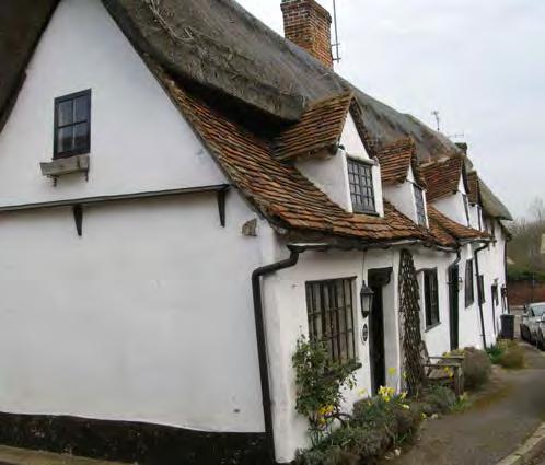
Cover image: The walling materials and finishes on old buildings were generally absorbent so allowed the fabric to ‘breathe’.
Photo: Matthew Slocombe
4
7
8
8
SPAB The Need for Old Buildings to
‘Breathe’2
.......................
.......................
.......................
.......................
1 Introduction
Modern buildings tend to rely on an impervious outer layer or a system of barriers to prevent moisture penetrating the walls, whereas buildings constructed before the mid-19th century generally rely on allowing the moisture which has been absorbed by the fabric to evaporate from the surface (see figure 1). The thickness of the wall alone in these earlier buildings may have been relied upon to achieve acceptably dry conditions internally.
The walling materials of old buildings in Britain are usually stone, brick, timber and earth (cob, wattle and daub), which are all absorbent. Mortars used to construct walls of brick and stone were usually of lime and sand, but earth or earth/lime mortars were sometimes used. The porous nature of these mortars permits evaporation of moisture from within the wall. As the mortars are usually more permeable than the materials they bond, walls are often dependent upon the evaporation of moisture from the joints to remain acceptably dry.
External rendering was usually lime-based, and therefore absorbent. Where this was used to improve the weather-resistance of the wall, it is common to find that this render has a rough open-textured surface, which tends to maximise the surface area and thus the amount of moisture able to evaporate is increased.
Buildings used to be decorated, internally and externally, almost exclusively with limewash, which could be coloured with natural pigments. Limewash is again, a porous material and allows the wall to ‘breathe’.
The concept behind the construction of old buildings is that moisture entering the wall should be able to evaporate. Whereas modern buildings rely on keeping water out by a system of barriers.
Technical terms used in this guidance are defined in our online glossary.1
Evaporation of moisture
Rain Rain
Cavity - barrier to penetrating dampness
Interstitial condensation (water vapour)
Damp-proof coursebarrier to rising damp
Evaporation of moisture
Rising dampness
1(a)
Interstitial condensation (water vapour)
Evaporation of moisture
1(b)
Rising dampness
Figure 1: Understanding the behaviour of old walls: (a) Basic modern cavity wall. (b) Solid wall of porous materials.

Illustrations: Philip Hughes
 SPAB The Need for Old Buildings to ‘Breathe’
3
2 Problems caused by the use of impervious materials

2.1 Different building types
In a modern building, the damage or failure of one of its moisture barriers will lead to severe problems of dampness penetration. In an old building, anything that prevents the evaporation of moisture from walls will lead to similar difficulties. Hence the two building types need to be handled in completely different ways: modern buildings will be damp without a barrier to moisture, because the economy of design does not provide a massive and absorbent structure, but old buildings will become damp if an impervious layer is applied to them, because this prevents water within the structure from evaporating.
As the moisture content of the wall increases, the likelihood of decay also increases. Timbers may succumb to wet or dry rot attack because their moisture content is too high. Timbers often occur in solid masonry walls in the form of lintels, spreaders for beam or joist ends, as bonding timbers or as fixing blocks. In masonry walls, the mortar will also be susceptible to decay if excessive moisture levels persist. This is particularly so of the lime/earth mortars used in vernacular buildings. Cob (a mixture of natural soil, straw and cow dung, compacted in layers to form walls) will decay extremely rapidly if it becomes wet and unable to dry out (see
2.2 Paint systems
Paint systems for exterior use tend to prevent evaporation of moisture from the surface. They are designed to prevent the ingress of moisture, but when used on the solid walls of old buildings, water inevitably gets behind the paint film in time (see figure 3). Unable to evaporate from the surface, this moisture is trapped and unless it is able to evaporate from the inner face of the wall the moisture content of the wall will gradually increase. In hot weather, moisture behind the paint film will vaporise, causing blistering, and in cold weather the wall surface may be damaged by frost action (see figure 4).
As the surface layer of paint begins to break down, further water penetration will occur leading to increased dampness.
2.3 External renders
Strong cement renders have a very similar effect to impervious paint films, but renders are even more susceptible to cracking and subsequent breakdown (see figure 5). The resulting decay is often more dramatic. Strong cement renders tend to form hair cracks as they set: these are hardly visible to the eye, but moisture enters the wall by capillary action. Once in the wall,
Figure 2: Water penetration has resulted in the decay of these cob walls. The cement render applied externally prevented them from drying out and led to the suddenness of the collapse.
Photo: Chris Shapland
prevented by the impermeability of the render. Where the render has been applied over soft brick or stone, severe breakdown of the weak underlying material can occur.
2.4 Pointing
External cement-rich pointing of an old wall has slightly different implications (see figures 6 to 9). Once again, water will get into the wall through the masonry or through cracks in the pointing, and due to the impermeability of the mortar will be unable to evaporate from the joints, as originally intended. Moisture within the wall will, therefore, have to evaporate from the surface of the masonry rather than from the pointing, leading to increased decay of the masonry due to the deposition of salts or frost action at its surface.
It is preferable that a soft lime mortar with rough texture and lower strength than surrounding masonry be used for pointing

and bedding. This encourages moisture to evaporate through the joints, rather than through the masonry units. Deposition of most of the salts will therefore occur at these mortar joints and the mortar will decay more rapidly than the masonry. Thus the pointing may be regarded as sacrificial. It is also, of course, cheaper and easier to repoint at intervals than to replace bricks or blocks of stone. This also helps to maximise retention of historic fabric.
2.5 Internal plaster
If the wall has been left with original lime plaster, then water unable to evaporate from the exterior will evaporate from the interior, with consequent disturbance to finishes. Furthermore, increased moisture content leads to decreased thermal insulation of a wall. Evaporation of moisture has a cooling effect on the surroundings and excessive levels of dampness will represent a considerable heat loss.


 Figure 5: Strong cement render on a cob wall. The render is being forced off the wall and is taking the surface of the cob with it. The cob behind this is decaying. Photo: Philip Hughes
Figure 3: Frequently overflowing hopper head and gutter have saturated the wall behind an impervious paint layer. Decay of the walling immediately behind the paint film has resulted in flaking.
Photo: Philip Hughes
Figure 4: Moisture trapped behind an impervious paint film has caused it to blister. The effect of salts and frost has led to further decay. Photo: Philip Hughes
Figure 6: Dense cement pointing splurged over the face of the stonework inhibits the evaporation of water from the wall and leads to rapid decay of the stone. Photo: Philip Hughes
Figure 5: Strong cement render on a cob wall. The render is being forced off the wall and is taking the surface of the cob with it. The cob behind this is decaying. Photo: Philip Hughes
Figure 3: Frequently overflowing hopper head and gutter have saturated the wall behind an impervious paint layer. Decay of the walling immediately behind the paint film has resulted in flaking.
Photo: Philip Hughes
Figure 4: Moisture trapped behind an impervious paint film has caused it to blister. The effect of salts and frost has led to further decay. Photo: Philip Hughes
Figure 6: Dense cement pointing splurged over the face of the stonework inhibits the evaporation of water from the wall and leads to rapid decay of the stone. Photo: Philip Hughes
SPAB The Need for Old Buildings to ‘Breathe’5
If dense plasters are used internally, moisture will again be prevented from evaporating and the level of dampness in the wall will increase. A gradual increase in salt concentrations within the wall and the deposition of crystals below the surface will tend to blow the plaster off the wall, or lead to expansion of the plaster layer itself and consequent bulging.

Where dense plasters are used to cover a wall suffering from rising dampness, the effect may be only to drive the moisture higher up the wall (see figure 10). This may cause old plaster which had remained sound hitherto to become affected, or may force moisture up the wall and into contact with timber, making it susceptible to decay.

2.6 Modern extensions
All the factors must be considered carefully when repairing, altering or extending an old building. Extensions cause particular difficulties because the materials in use for the new extension will often be quite unsuitable for works to the fabric of the old building, and yet it is common for work to be carried out on new and old at the same time. It is important to take great care to ensure that damaging work is not executed. Where a full specification has been prepared, it may be necessary to include two sets of workmanship and materials clauses: one set for the new extension and one for work to the existing building.
RainRain
Water in liquid form
Strong cement pointing
Deposition of salt crystals
Interstitial condensation (water vapour)
Evaporation of moisture
Usual decay pattern when mortar used for pointing is softer and more porous than walling material

9(a)
Evaporation of moisture
Water in liquid form
Interstitial condensation (water vapour)
Deposition of salt crystals
Usual decay pattern when wall materials are more porous than pointing
9(b)
Rising dampness Rising dampness
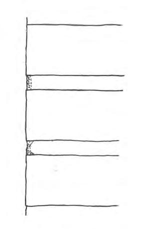 Figure 7: Strong cement-based mortar survives while the wall it was used to point up decays. This could have been avoided by the use of a lime-based mortar, weaker than the brickwork.
Photo: Philip Hughes
Figure 8: This wall has been repointed in a cement-based mortar. It is suffering severely from the deposition of salts. Efflorescence is occurring on the surface of the bricks instead of on the mortar joints as would be the case had a porous lime mortar been used.
Photo: Philip Hughes
Figure 9: Movement of moisture: (a) Wall built of porous materials. (b) Effect of imperious pointing. Illustrations: Philip Hughes
Figure 7: Strong cement-based mortar survives while the wall it was used to point up decays. This could have been avoided by the use of a lime-based mortar, weaker than the brickwork.
Photo: Philip Hughes
Figure 8: This wall has been repointed in a cement-based mortar. It is suffering severely from the deposition of salts. Efflorescence is occurring on the surface of the bricks instead of on the mortar joints as would be the case had a porous lime mortar been used.
Photo: Philip Hughes
Figure 9: Movement of moisture: (a) Wall built of porous materials. (b) Effect of imperious pointing. Illustrations: Philip Hughes
SPAB The Need for Old Buildings to ‘Breathe’6
3 The correct treatment of old buildings
Under normal circumstances, older buildings will function well if they are allowed to work as they were intended to do. Mortars, plasters, renders and finishes should all be of relatively permeable materials, allowing moisture to pass through them and evaporate from the surface.2
Traditionally mortars, plasters and renders were usually lime-based, and decoration was with limewash.


In the case of an old building which has already been treated in some way with an impervious material, watch the building carefully for any signs of the problems mentioned in this Advice Note, and at the first sign of these occurring take remedial action if possible (see figures 11 and 12).
Remedial action should ideally involve the removal of any impervious materials and their replacement with permeable ones. This is not always possible without doing further damage to the fabric of the building and compromise may be necessary.
Cement renders can sometimes be removed after working over the surface thoroughly with a hammer to fracture the render into small units (see figure 13). Levering off large sheets of render will cause severe damage to soft underlying materials. Where a render is so hard that it does not respond, it is probably best to leave it to age naturally. Rendering should be in a lime mix.3
 Figure 10: Strong cement-based render has been used to replace plaster affected by dampness on the lower part of these massive walls. As a result the dampness has risen higher in the wall and has now affected the old plaster that had remained sound.
Photo: Philip Hughes
Figure 11: Salt crystallisation behind the strong cement patches on this plinth has led to both these being forced off and to further disintegration of the stonework.
Photo: Philip Hughes
Figure 12: Strong cement pointing being forced off the wall by crystallisation of salts behind. Increased levels of dampness within the wall have caused decay of the earth-lime mortar, leading to compaction of the wall – also forcing off the dense pointing.
Photo: Philip Hughes
Figure 13: Cement render has been applied over a lime roughcast on this timber-framed building. The cement is being carefully removed in small pieces by forming hairline cracks with a lump hammer.
Photo: Philip Hughes
Figure 10: Strong cement-based render has been used to replace plaster affected by dampness on the lower part of these massive walls. As a result the dampness has risen higher in the wall and has now affected the old plaster that had remained sound.
Photo: Philip Hughes
Figure 11: Salt crystallisation behind the strong cement patches on this plinth has led to both these being forced off and to further disintegration of the stonework.
Photo: Philip Hughes
Figure 12: Strong cement pointing being forced off the wall by crystallisation of salts behind. Increased levels of dampness within the wall have caused decay of the earth-lime mortar, leading to compaction of the wall – also forcing off the dense pointing.
Photo: Philip Hughes
Figure 13: Cement render has been applied over a lime roughcast on this timber-framed building. The cement is being carefully removed in small pieces by forming hairline cracks with a lump hammer.
Photo: Philip Hughes
SPAB The Need for Old Buildings to ‘Breathe’7
Cement pointing should be cut out but sometimes it adheres so well that its removal will damage the surrounding masonry. In these circumstances it is usually best to leave what cannot be removed easily and to patch point with a lime-based mortar.4
Paints can sometimes be scraped off when they have started to blister and peel or may be removed by any of the methods suggested in the SPAB Information Sheet on Removing Paint from Old Buildings. Paints which adhere strongly and which resist the usual removal methods are best left until they age. If, in the latter case, they should become patchy, the wall can be redecorated in limewash until the paint is sufficiently decayed to remove.
Where walls have been mistreated in any of the ways mentioned, it is essential they are kept as dry and as well ventilated as possible. Water must not be allowed to enter the top of the wall or behind the impervious material.
Solid walls which have become saturated may take many months or even years to dry out. During the drying process, salts will be deposited on the surfaces, and this can lead to severe breakdown of the materials. In some cases it may be necessary to poultice the wall or apply another finish over it to draw the salts out of the masonry. This is particularly important where ornamental work may be at risk.
If in any doubt, seek professional advice from an architect or building surveyor experienced in the repair of historic buildings. The SPAB can usually suggest names of people with experience in this field.
4 References
1 See https://www.spab.org.uk/advice/glossary
2 for more about permeability, see SPAB
statement on Breathability and Old Buildings
3 Further advice on lime renders is given in English Heritage, 2011
4 For more about repointing, see SPAB
Technical Pamphlet 5 on Repointing Stone and Brick Walling
5 Other advice
5.1 Contacts
Where work to old buildings is being considered, the SPAB may be able to suggest suitable specialists, including contractors.
5.2 Further reading
English Heritage (2011) Mortars, Renders and Plasters, Practical Building Conservation , Farnham: Ashgate Publishing Ltd
English Heritage (2012) Timber, Practical Building Conservation, Farnham: Ashgate Publishing Ltd Kent, D D (2018) Control of Dampness, SPAB Technical Advice Note, London: SPAB. Available at: https://www.spab.org.uk/sites/ default/files/SPAB%20Control_of_Dampness_ Edn_01_Rev_01_0.pdf
Oxley, R (1999) Is Timber Treatment Always Necessary? An Introduction for Homeowners, SPAB Information Sheet 14, London: Society for the Protection of Ancient Buildings Schofield, J (1985) Basic Limewash, SPAB Information Sheet 1, London: Society for the Protection of Ancient Buildings
Slocombe, M (2017) The SPAB Approach to the Conservation and Repair of Old Buildings, London: Society for the Protection of Ancient Buildings
Society for the Protection of Ancient Buildings (1990) The Surface Treatment of Timber-Framed Houses, SPAB Information Sheet 3, London: Society for the Protection of Ancient Buildings Society for the Protection of Ancient Buildings (2016) Breathability and Old Buildings. Available at: https://www.spab.org.uk/advice/ breathability-and-old-buildings
Torraca, G (1988) Porous Building Materials: Materials Science for Architectural Conservation, 3rd edition, Materials Science for Architectural Conservation, Rome: International Centre for the Study of the Preservation and Restoration of Cultural Property. Available at: https://www.iccrom.org/sites/default/ files/2018-02/2005_torraca_porous_building_ eng_106444_light.pdf (Accessed 13 February 2020)
Wright, A (1994) Removing Paint from Old Buildings, 3rd edition, SPAB Information Sheet 5, London: Society for the Protection of Ancient Buildings
SPAB The Need for Old Buildings to ‘Breathe’
8
The content of this publication is offered in good faith, but neither the author nor the Society can accept responsibility arising from incorrect or incomplete information that may be included. The use of traditional materials may incur risks that are different from those associated with modern materials. Manufacturers’ and suppliers’ guidelines should always be observed. This document is intended as a contribution to a continuing debate and we welcome comments.
Written by Philip Hughes. This publication revises and supersedes our former Information Sheet 4 (1st edition, 1986 as amended). The author is indebted to Paul Bedford for his help with the preparation of this document. Grateful thanks to Judith Rodden for editorial advice. Produced by Catherine Peacock. The sources of illustrations are given adjacent to them together with any copyright where not belonging to the SPAB.
The help and advice of the following with the first edition is also acknowledged: Ian Angus, Shawn Kholucy and Annette Downing.
Warning
The term ‘breathing’ is often applied to many products which are only slightly vapour permeable. In general, no synthetic modern materials should be applied to the masonry or plaster surfaces of historic buildings. If in any doubt, contact the SPAB.
The Society for the Protection of Ancient Buildings (SPAB) believes old buildings have a future. From cottages to castles and from churches to cathedrals we are here to help buildings and the people who care for them. Through our unique training schemes, courses, advice and research we help people put our expertise into practice.
Today the SPAB encourages excellence in new design to enrich and complement the built historic environment. We train new generations of architectural professionals and building craftspeople to conserve this landscape with sensitivity and skill, and we play a statutory role as adviser to local planning authorities. In our casework we campaign actively to protect old buildings at risk.

SPAB: hands on history. Join today to support our positive, practical approach to building conservation.
Published by the SPAB in February 2020
© SPAB 2020 Edn 2 Rev 0
SPAB ref: T5304M www.spab.org.uk
ISBN 978-1-898856-39-9
The Society for the Protection of Ancient Buildings 37 Spital Square, London E1 6DY Tel 020 7377 1644 info@spab.org.uk www.spab.org.uk
A charitable company limited by guarantee registered in England and Wales Company No 5743962 Charity No 111 3753 VAT No 577 4276 02
Control of Dampness
SPAB Technical Advice Note
 Douglas Kent BSc (Hons), BSc, MSc, MRICS
The Society for the Protection of Ancient Buildings
37 Spital Square London, E1 6DY 020 7377 1644
info@spab.org.uk www.spab.org.uk
Contents
Most forms of deterioration that affect old buildings in the United Kingdom are attributable to the presence of excessive moisture. Dampness promotes timber decay, the corrosion of metals and even structural collapse. It mobilises soluble salts that harm masonry and increases frost damage. Damp fabric also reduces thermal efficiency. Dampness inside buildings spoils plasterwork, decorations and furniture, and creates conditions that are uncomfortable or harmful to the health of occupants.
This Technical Advice Note explains the nature and causes of dampness together with its diagnosis, control and prevention in buildings predating c1919. Despite dampness problems being commonplace, their cause is frequently misdiagnosed and ineffective remediation undertaken. Unnecessary treatments are often carried out, including the insertion of damp-proof membranes to create barriers to moisture. Action to address basic maintenance or lifestyle issues is usually more appropriate, as well as measures that respect the need for old buildings to ‘breathe’.
Cover image: Dampness problems are commonly misdiagnosed. Rainsplash, as shown here, is incorrectly stated to be rising dampness in many cases.
Photo: SPAB
1 Introduction ....................... 3 2 Sources and symptoms ....................... 5 3 Causes ....................... 8 4 Diagnosis ....................... 11 5 Work in general ....................... 13 6 Control ....................... 15 7 Prevention ....................... 22 8 References ....................... 22 9 Other guidance ........................ 23
1 Introduction
The term ‘dampness’ is used in the context of buildings to refer to the presence of excessive moisture that, if not addressed, may harm them or their occupants (see figure 1).
The source of this moisture can be either liquid water or water vapour in the air. Buildings remain dry when water from various ‘moisture sources’ (for example, moist, warm air rising out of a bath) is balanced by its dissipation via ‘moisture sinks’ (such as good ventilation for a humid bathroom) or storage in ‘moisture reservoirs’ (for instance, absorbent materials). If this equilibrium is upset, however, buildings may become damp.
To understand how this equilibrium arises in older buildings, it is necessary to consider first the way they are built (see figure 2). Pre-c1919 buildings are typically of ‘traditional’ construction. They tend to have solid walls, and sometimes solid floors, built using ‘breathable’ materials that allow the free passage of moisture.1 These include stone, soft brick, unfired earth, lime-based mortars and plasters, and limewash. They take in more moisture than their modern substitutes but allow it to evaporate readily when conditions become drier.

As well as being of traditional construction, many older buildings are vernacular (indigenous) in nature so possess features adapted for the local climate. The UK’s maritime climate means that pitched roofs to shed water quickly are usual, generally with gutters and downpipes or otherwise generous overhanging eaves.

Ventilation through gaps where tile (or slate) beds against tile, dries out any damp timbers
Wind dries the external surfaces
Limewash holds any condensation until it can be re-evaporated
Evaporation of rising dampness
Damp rising through floor Evaporation of rising damp Simple lifestyle generates only small quantities of water vapour
Open fires drawing large quantities of air
Penetration by driving rain
Figure 1: Dampness can lead to serious deterioration if left unattended, as with this cottage that was later demolished as a result.
Photo: Douglas Kent
Figure 2: The movement of moisture through a traditionally constructed building. Illustration: SPAB
Wind blown rain and snow
SPAB Control of Dampness3
During rain, a certain amount of moisture deposited on the outer face of a solid wall will be taken in by capillary action and seep slowly inwards. The vapour permeability of the building fabric will enable this moisture to be drawn back to the surface and evaporate when the rain has stopped, before it can reach the inner face, although extra protection is sometimes required.
Various traditional methods exist to give walls extra protection from the rain with little hindrance to evaporation. These include the application of lime render, comprising roughcast (or harling) in more exposed regions, with limewash.2 Slate-hanging is an alternative seen in the south-west and tile-hanging in the south-east. Weatherboarding is associated with the south-east and parts of East Anglia. Good weatherings are important, too, such as projecting cills, stringcourses, hood moulds and pentice boards (see figure 3). Internally, solid walls can be lined with lath and plaster on timber battens to create an air gap that reduces the likelihood of moisture penetration.
Most pre-c1919 buildings were built without damp-proof courses (DPCs) or damp-proof membranes (DPMs) to act as barriers to moisture in walls and floors respectively. Moisture will rise to some degree as it is drawn by capillary action into the pores of permeable materials, such as brick or stone, that are in contact with damp soil. This is usually not a problem where the construction can ‘breathe’, allowing evaporation.
The absorbed moisture will rise in a wall to a height at which there is a balance between the forces of capillary rise and that of gravity and evaporation. This height will vary somewhat
with the time of year, wall thickness, pore size and the level of the water table in the ground. Flagstone or brick floors used to be laid directly upon the bare earth and the moisture that rose through these floors would be carried away by ventilation (see figure 4). Additionally, the hygroscopic nature of many traditional building materials means they absorb small quantities of moisture from the air when it is humid and rerelease it under drier conditions.

Old buildings are not inherently damp. Before central heating was commonplace, they were heated by open fires that drew in large quantities of air through loosely fitting windows and doors. Generally, this high rate of ventilation would have quickly evaporated ‘structural moisture’ from the breathing fabric internally while such moisture on external wall surfaces would be driven away by the wind. There was, therefore, in theory, an inherent equilibrium.
In practice, this equilibrium may be upset for various reasons with the consequence that liquid water persists for long enough to adversely affect the physical structure of materials, or that relative humidity increases to a detrimental level of 70% or higher. Where dampness exists, it should not be ignored. Although a decision may be taken not to carry out any remedial work, this should only be made after the dampness has been investigated carefully.
This Technical Advice Note considers next the sources and symptoms of dampness, along with its causes (sections 2 and 3). Understanding these is an important prerequisite for diagnosing, controlling and preventing dampness problems (sections 4 to 7).
Figure 3: Traditional architectural details, such as pentice boards, function to protect buildings from the rain.
Photo: Douglas Kent
Figure 4: Traditional solid floors allow the ready evaporation of below-ground moisture from their surfaces.
Photo: Douglas Kent
SPAB Control of Dampness4
2 Sources and Symptoms
2.1 Types of dampness
There are different types of dampness. They are classified according to their source and the distinction between them is important to understand because each requires different treatments. The sources of dampness fall into two main categories:
• From liquid moisture: This includes rainwater penetration, below-ground moisture and plumbing leaks. Flooding is beyond the scope of this guidance.3
• From the air: This covers condensation, high humidity and dampness due to hygroscopic salts.
2.2 Rainwater penetration
Rainwater penetration refers to the ingress of rainwater at various points in the external envelope of a building. It can occur directly through roofs, chimneys and openings, such as windows and doors. It can also happen indirectly, for example, via spillage from a blocked or leaking gutter or gulley through an external wall or ground floor. Rainwater penetrates buildings by various mechanisms, for example, gravity, wind pressure and capillary action.
Rainwater penetration usually produces welldefined damp patches or leaks. The dampness


may evaporate in a few days but will reappear after a period of heavy rain. The symptoms of rainwater penetration internally include stains and peeling paint on ceilings, external walls and chimney breasts. Outside, signs of rainwater penetration may be dark patches that appear after rain, especially on the more exposed parts of a building, such as chimneys, parapets and south-west or west-facing walls, as well as near gutters and downpipes. Patches of green algal growth externally are also commonly attributable to rainwater penetration. (See figures 5a and 5b.)
2.3 Below-ground moisture (including rising dampness)
Below-ground moisture problems relate to the entry of groundwater into a building. This may take place laterally, for example, through a cellar wall under hydrostatic pressure. Alternatively, moisture may enter via upward movement through the bases of walls or floors. This is often due to capillary action, where the result is termed ‘rising dampness’. Rising dampness is usually much less of a problem than commonly supposed. It may extend only 10 to 50 mm above the internal floor level in walls, though can rise to 900 mm or higher, depending on the external ground levels, masonry type, water table level and evaporation rate. (See figure 6.)
The symptoms of groundwater moisture in a building include moist patches on floors and damp floor perimeters. The level of the water table can vary but in general the dampness is more constant than that arising from rainwater penetration. Contaminating salts may be seen as white deposits or feathery crystals. On walls, the effects of rising dampness exhibit a sharp
Figures 5: Common symptoms of rainwater penetration. (a) Water staining internally. (b) Green algal growth externally.
Photos: Douglas Kent
5(b)
SPAB Control of Dampness5
5(a)
change from wet to dry or a ‘tidemark’ stain on finishes. They can also include peeling paint, rotten skirting boards, and possibly mould and an accompanying musty smell.

2.4 Plumbing leaks
The escape of liquid water inside a building from water supply or waste water systems will cause dampness or localised flooding. This may arise where tanks, pipes, valves, radiators, sanitary fittings and appliances, such as washing machines, develop leaks. Dripping overflow pipes for WC cisterns are a further source. (See figures 7a and 7b.)
The symptoms are localised stains, sometimes with a fan-like pattern, and a presence of moisture that is unrelated to the weather. Plumbing leaks may be associated with
mould growth, as well as decay in ducts or voids (although this will frequently not be immediately visible) and can, therefore, result in severe decay if there has been even a slight but long-term problem. Leaks can sometimes be heard or noticed because of higher than usual water bills.


2.5 Condensation
Condensation is the release of water that occurs internally when air comes into contact with colder building components so is cooled to its dewpoint temperature and can carry less moisture as vapour. Condensation is, therefore, dependent upon the temperature of surfaces and the humidity of the surrounding air.
Condensation commonly affects rooms where a large amount of moisture is produced, such as kitchens, bathrooms and bedrooms. It is also found in areas where ventilation is inadequate, particularly in lofts, subfloor voids and chimney flues.⁴ Wardrobes and cupboards built against external walls are often badly affected, as well as room corners and walls behind furniture or pictures. North-facing walls are particularly prone to condensation problems. Condensation is an intermittent form of dampness. It is usually worse in rainy weather but is not dependent on rain.
The condensate will form tiny droplets of moisture on hard, shiny surfaces, for example, glass, metal or plastic-based paint. Because single-glazed windows commonly provide the coldest surface inside a room or space in winter, condensation usually forms on these first – with the glazing acting effectively as a dehumidifier. (See figure 8.)
Control of Dampness
Figure 6: Rising dampness exists but is rarer than commonly supposed.
Photo: Caroline Rye
Figure 7: Plumbing leaks associated with: (a) Defective pipework above a kitchen unit (b) Overflowing WC cistern.
Photos: Douglas Kent
7(b)7(a)
SPAB
6
There may be accompanying rot in softwood window frames. Where windows are doubleglazed, condensation often occurs on the adjacent plaster reveals instead. At other times of the year, surfaces such as stone flags at ground level or the lower part of ground floor walls may be affected.
Condensation on porous surfaces, as with lime plastered walls, is characterised by diffuse areas of moisture. It is often accompanied by black mould on wallpaper and plaster, and white spot mould on timber in voids (see figure 9).The acidic condensate formed within chimney flues will attack mortar and can carry tarry deposits through the brickwork into the building to stain wallpaper or plaster.⁵

Interstitial condensation – as opposed to surface condensation - occurs within building elements, such as walls. Water vapour exerts a pressure that causes humid air to move through permeable building materials towards drier air

on the other side, usually the outside. Interstitial condensation results when the temperature of the diffusing water vapour falls below its dewpoint within the construction. The resulting dampness will reduce the thermal insulation value of the building fabric, in turn increasing the risk of condensation on the internal surface.
2.6 Hygroscopic salts
This form of dampness is linked to hygroscopic salts, such as chlorides and nitrates, that absorb moisture from the air when it is humid. Some salts are so hygroscopic (or ‘deliquescent’) that they dissolve in the moisture they absorb. Additionally, as salts cycle through their liquid and crystal phases in response to humidity fluctuations (ie between deliquescence and drying), recrystallisation within the pores of masonry leads to its damage.
Prolonged rising dampness can leave a wall contaminated by hygroscopic salts carried up

 Figure 10: Hygroscopic salt deposits can be a sign of a current or past rising dampness problem.
Photo: Douglas Kent
Figure 11: Decay of floor structures can result from high humidity in voids below. Photo: Douglas Kent
Figure 8: Condensation forms on the coldest surfaces first, such as windows or their surrounding reveals.
Photo: Douglas Kent
Figure 9: Black spot mould is commonly associated with condensation. Photo: Douglas Kent
Figure 10: Hygroscopic salt deposits can be a sign of a current or past rising dampness problem.
Photo: Douglas Kent
Figure 11: Decay of floor structures can result from high humidity in voids below. Photo: Douglas Kent
Figure 8: Condensation forms on the coldest surfaces first, such as windows or their surrounding reveals.
Photo: Douglas Kent
Figure 9: Black spot mould is commonly associated with condensation. Photo: Douglas Kent
SPAB Control of Dampness7
from the ground (see figure 10). Their presence will keep moisture levels high even after the rising dampness itself has been eliminated. Hygroscopic salts can also be deposited within chimney flues from combustion gases and will remain long after flues have been disused, causing dampness on plasterwork around chimney breasts.

The symptoms of dampness due to hygroscopic salts will be increased moisture levels when conditions are muggy. Salt concentrations may be evident in locations where evaporation occurs but deposits are not always visible.
Efflorescent salts, usually sulfates, also occur in damp buildings. Efflorescence indicates that water has passed through a material, leaving white or off-white salty deposits. Efflorescent salts, while unsightly, are seldom hygroscopic so do not absorb moisture from the atmosphere.
2.7 High humidity
Exceptionally high levels of relative humidity alone can result in dampness, especially under suspended timber ground floors but also in cellars. Wood is hygroscopic so its moisture content varies with the temperature and humidity of the surrounding air. In a normal, dry living environment, the moisture content of timber will generally be between approximately 9 and 16%. Where it exceeds 21%, timber becomes susceptible to fungal decay. The symptoms of dampness resulting from high humidity, therefore, are decayed floor structures, though dry rot fungal decay can also travel across masonry without harming it. (See figure 11).
3 Causes
3.1 Understanding the problem
It is important to understand the causes of dampness problems, as well as their signs and symptoms, because this will help when it comes to implementing effective control measures. Addressing the cause of dampness is always preferable, where possible, to dealing merely with the symptoms.
3.2 Poor maintenance and damage
Neglect (especially where access for maintenance is difficult), deterioration and vandalism are commonly associated with rainwater penetration. (See figures 12a and 12b.) Problems will be most acute during prolonged spells of heavy rain.

Leaves, moss and dirt can build up quickly in gutters and hopper heads, obstructing the free passage of water and causing leakage or overflow. Leaks from parapet and valley gutters are particularly serious because the spaces beneath tend to be warm, poorly ventilated and contain the bearings of the roof trusses. In these conditions, water from blocked or defective parapet/valley gutters can give rise to severe fungal growth.
Cracked hopper heads or downpipes, especially where the crack may be undetected against the wall, are another source of dampness in walls. A downpipe will often become choked with leaves, causing water to back up the pipe and spurt out of the joints or cracks onto the adjacent wall. Such concentrated and continued
Figure 12: (a) Rainwater penetration due to missing gutter. (b) Damage from lead theft.
Photo: Douglas Kent
12(b)12(a)
SPAB Control of Dampness8
wetting is likely to erode mortar joints, corrode fixings (potentially leading to further failure), promote moss growth externally, which prolongs the dampness by retaining moisture, and may also lead to frost damage. (See figure 13.)
Defective drains or gulleys, or leaking water pipes can add considerably to the moistureload of the ground in proximity to the base of walls. Often problems of rising dampness are caused by failures of this nature rather than the presence of ground water per se.


Driving rain can penetrate even a thick wall through weak points, such as cracks and open joints. Roofs, chimneys and parapets, normally being the most exposed parts of a building, are particularly susceptible to rainwater penetration. Something as straightforward as a displaced tile or defective flashing or mortar fillet can cause significant damage. Water may also be drawn by capillary action through cracks in leadwork.

3.3 Inappropriate methods and materials
Traditional and modern buildings handle moisture in different ways and mixing the two types of construction can cause dampness. Unlike older, traditional construction with solid walls and floors that rely on the need to ‘breathe’ to stay dry, modern buildings are normally built with cavity walls and floors that employ ‘vapour-closed’ materials of low permeability, for example, ordinary Portland cement. They depend on excluding water with barriers and moisture breaks. The two types of construction are like overcoats and raincoats respectively. Old buildings usually become damp when barriers to moisture are added. New buildings, on the other hand, become damp when such barriers fail.
Any impervious covering, such as linoleum, vinyl etc, laid over a solid ground floor in contact with the ground will become soaking wet underneath and problems may also follow the installation of a DPM. Water trapped under the floor could be forced up the walls and, where there is no DPC, cause rising dampness there. The installation of a DPM in the floor of a cob, wychert, clay lump or other earth-walled building can increase dampness in the walls to such a degree that they collapse.
Attempts to seal walls (for example, with dense plasters, polyvinyl acetate (PVA) or impervious paint) will impede the evaporation, trapping moisture or displacing it elsewhere, and can lead to spalling or powdering of surfaces.⁶ (See figures 14a and 14b.) The use of impermeable plastic-based materials for decoration and repair also results in more humid internal environments and tends to encourage condensation.
Figure 13: Moss growth can compound problems arising from rainwater penetration. Photo: Douglas Kent
Figure 14: Traditional, solid walls can suffer from dampness and deterioration where inappropriate impermeable finishes are used, such as: (a) Plastic-based paints. (b) Bitumastic products.
Photos: Douglas Kent
SPAB Control of Dampness9
14(a) 14(b)
Modern cement renders and pointing are brittle, of low permeability and tend to crack easily as walls undergo small thermal or structural movements (see figure 15). Water commonly streams down the surface of such render and is drawn into fine cracks by capillary action where it becomes trapped. Consequently, moisture may build up behind the render and eventually find its way to the inside face.
Using hard cement renders, vapour barriers or impermeable thermal insulation on walls also increases the likelihood of interstitial condensation. Cement renders hinder the evaporation of moisture in the wall from the external surface. In certain solid walls at specific times of the year, moisture bound within the wall fabric may evaporate from both the external and internal wall faces. For these walls, the inclusion of a vapour control layer (VCL) close to the internal wall face will restrict the amount of moisture accessing the surface for evaporative purposes and may cause moisture to accumulate in the masonry of the wall. This is also likely with internally insulated walls that incorporate a VCL.
Other inappropriate work includes the stripping of lime render from buildings – a practice longopposed by the SPAB and which lead to its early nickname of the Anti-Scrape Society.

3.4 Reduced ventilation

Compared to their modern counterparts, older buildings require greater ventilation to remove structural moisture from their breathing fabric, in addition to the water vapour generated by the activities of their occupants. Even though old buildings are often overgenerously
ventilated, excessive draughtproofing and the installation of double-glazing has contributed to an increase in condensation problems in recent years. Ventilation levels should not be reduced excessively (to below 0.4-0.5 ach).⁷
Chimney flues can become damp through condensation because modern boilers and closed stoves draw in considerably less air than open fires. The warm humid flue gases rise slowly and are likely to condense on any part of the flue which is exposed or has poor thermal insulation. Disused flues may also suffer from condensation if they are closed off without adequate ventilation at the top and bottom.
Experience shows bitumen-coated fabric on the outside of roofs or spray-on coatings underneath prevent proper inspection, hinder the reuse of slates or tiles and, by reducing ventilation, increase the risk of timber decay. They are a false economy, and cases have been reported of serious damage resulting to the structure. These treatments can adversely affect the mortgageability of properties.
The blocking up of subfloor vents may lead to condensation problems and serious timber decay in the associated voids.
3.5 Modern lifestyles and use
Our modern, more sedentary, interior lifestyles have changed the moisture equilibrium in old buildings. Internal room moisture is increased by cooking and washing activities (such as drying laundry, boiling kettles and bathing) that can distribute more moisture into rooms.
Condensation may occur in a thick-walled or solid-floored building of high thermal capacity,
SPAB Control of Dampness
Figure 15: Hairline cracks resulting from the inappropriate use of cement render on traditionally constructed buildings can admit moisture via capillary action. Photo: Douglas Kent
Figure 16: The use of moisture-generating bottled gas heaters is best avoided in thick-walled, solid-floored buildings.
Photo: Douglas Kent
10
such as a church, if it is heated intermittently, particularly where moisture-generating flueless bottled gas stoves and heaters are used. (See figure 16.) The heating installation does not have time to warm the surfaces above the dewpoint temperature, so moisture from the already warmed air condenses on them. (A rapid change from cold to warm, humid weather can produce a similar effect.)
Additionally, where patios, paths and other hard surfaces are laid up to walls, inadequate drainage or rainsplash commonly soaks them.
Moisture movement can increase when central heating is first installed or turned on after the summer months: sometimes soluble salts are drawn to the wall surface that crystallise. The effect can be cyclical with salts going back into solution when the internal relative humidity rises and then being redeposited.
3.6 Poor workmanship and detailing
Rainwater penetration can be caused by poor workmanship. An example is where roof tile laps are reduced by stretching the gauge during retiling to economise on materials. This will increase the chances of moisture penetration, including as a result of wind-driven rain or ingress by melting snow on roof slopes.

Poor detailing can also cause dampness. Cold spots from gaps in insulation are conducive to condensation. Roofs on porches or extensions may be of inferior quality, with poor weatherings and rainwater disposal.
4 Diagnosis
4.1 Methodical investigation
An accurate diagnosis of the type and cause of a dampness problem is essential if it is to be treated effectively. It is alarming, however, how often this stage is skipped or a problem misdiagnosed. This can lead to unnecessary and expensive ‘remedial’ work that damages the building fabric, notably through some irrelevant solution for a non-existent rising dampness problem (see section 4.3).
Sometimes the diagnosis may be self-evident, (see figure 17); frequently, however, it is less obvious and needs investigating. Applying staged remedies can help to accurately diagnose the cause of dampness. Before embarking on extensive work, therefore, the first step may entail nothing more than basic maintenance, such as clearing a blocked gulley, to see if it addresses the problem or further action is needed.
It might be necessary to employ an appropriate independent specialist to diagnose a dampness problem. It is strongly advisable to seek advice required with diagnosing a major dampness problem separately from quotations for work to address it. Taking such advice first (for example, from a chartered building surveyor or other appropriately qualified individual) will prevent vested commercial interests giving rise to recommendations for more work than is strictly necessary (which can occur when a remedial treatment contractor is asked to both diagnose and resolve dampness). Free surveys are also best avoided.
In the SPAB’s experience, mortgage lenders can demand unnecessary damp-proofing work during house purchases. Although mortgage valuers have a duty to follow a trail of suspicion, some simply pass all responsibility onto remedial treatment contractors with a vested commercial interest encouraging over-specification. It is worth challenging any diagnosis you believe is questionable and, if necessary, seeking a second opinion in writing from an independent chartered building surveyor or consultant (note, not contractor). The SPAB may be able to advise you on suitable names.
A methodical step-by-step approach is advocated, as described in sections 4.2 to 4.5.⁸
Figure 17: Diagnosis of a dampness problem is sometimes, but not always, obvious.
Photo: Douglas Kent
SPAB Control of Dampness11
4.2 Step 1: Visual inspection
The human senses must not be undervalued because the sight, feel and smell of dampness can often provide adequate information. Be very wary of tasting deposits to determine the presence of salts, however, because hazardous chemicals, such as entachlorophenols, were used in the past to treat areas of decay. The starting point is to check for the symptoms discussed earlier in section 2, taking into consideration the date the property was built, whether it is unoccupied or unheated, the occupancy type, exposure and recent weather, dampness duration, location, colour and shape of patches, stains, mould and salts.
A careful inspection of the roof, parapets, parapet and valley gutters, and abutments should be made, especially exposed horizontal surfaces and areas likely to collect water. Water from leaks can run down rafters or, more occasionally, the underside of the roof to appear inside the building some distance away.
It is often instructive to observe the performance of the rainwater disposal system below the roof during heavy rainfall. The rainwater head, gutters and downpipes that appeared to deal adequately with average rainfall can fail under heavy and prolonged periods of rain. There have been occasions when dampness has been due to the failure of downpipes which had been embedded at an earlier date within walls. The inspection of gulleys during rain can also reveal blockages.
The height of ground levels and condition of external wall faces should be examined carefully. Pay particular attention to the pointing, which can be very vulnerable to water penetration. Traditional lime mortars tend to absorb moisture and release it later. Modern cementitious mortars often permit water penetration through hairline cracks on the perimeter of, and within, the pointing material.
Joints in protruding elements such as parapets are particularly vulnerable, especially if not covered (for example, with lead sheet or slate).
4.3 Step 2: Electrical moisture meters (EMMs)
Diagnosis sometimes requires more scientific approaches than the sight, feel and smell of dampness. Dampness can be hazardous long before it is detectable by human senses and electrical moisture meters help to establish the presence and amount of moisture scientifically. (See figure 18.)
Using electrical moisture meters to plot the distribution of moisture can give very helpful clues about its source (Table 1). Electrical moisture meters are also particularly useful for detecting changes in the moisture content of materials.
Rising dampness is widely misdiagnosed on the basis of high electrical moisture meter readings alone. Elevated readings occur frequently in old buildings that are not unduly damp, due to salt deposition from evaporation associated with a previous dampness problem, or the presence of certain timber preservatives, foil-backed wallpaper or carbon-containing materials (for example, in breeze blocks or black wallpaper coatings); or they can indicate another problem altogether, such as penetration from rainsplash or condensation.

If rising dampness exists, there will be visible indications too, such as an accompanying tidemark.
Various accessories are available for use with EMMs, for example, hammer electrodes that can be helpful when measuring the moisture content in joists without lifting floorboards.
4.4 Step 3: Detailed investigation
An in-depth investigation is likely to be required to help build up a better picture of a dampness problem if steps 1 and 2 have not enabled a diagnosis.
Salt tests can provide valuable information and be undertaken on site using an analysis kit or use made of a laboratory service. Typical results of salts testing are given in Table 2.
SPAB Control of Dampness
Figure 18: Electrical moisture meters have a role to play in diagnosing problems when used in the correct hands.
Photo: Douglas Kent
12
Dampness Source Distribution of meter readings
Rainwater penetration
For liquid moisture
Below-ground moisture
Usually tail off sharply
Tail off sharply with height
Plumbing leaks Normally localised
Condensation Tail off gently
Dampness Source Salts present
Rainwater penetration No salts typically (possibly sodium chloride near coasts)
For liquid moisture
Below-ground moisture Nitrites and generally chlorides – important clue
Plumbing leaks Chlorides & possibly nitrates
Other Chlorides from urine or sea water
Condensation No salts (hence mould)
For moisture from the air
Hygroscopic salts (for example, due to a previous dampness problem)
Usually tail off fairly sharply above and below the area of salt deposition unless there is a continuing source of moisture.
Table 1: Electrical moisture meter readings9
Relative humidity and dewpoint can be ascertained with instruments such as the whirling hygrometer. The use of other equipment can also be helpful, including infrared cameras for mapping moisture. These detect temperature differences. Wet areas will usually have a different temperature to dry ones, due to, for example, evaporative cooling. Wooden or metal ‘listening sticks’ or stethoscopes can be used in other situations to detect plumbing leaks.
4.5 Step 4: Further testing and monitoring
In some cases, it will be necessary to carry out more advanced forms of testing to diagnose the cause of a dampness problem. Such tests include the use of carbide meters or the gravimetric (oven-drying) method. They are time-consuming and intrusive but can help avoid unnecessary and harmful work by, for example, determining whether a wall is significantly damp within its thickness.
Some monitoring of the internal environment within a building may also be beneficial. Modern data loggers, which are more versatile and less expensive than their earlier counterparts, have the advantage of providing a longer-term picture of conditions than a one-off assessment, so can assist, for instance, in determining seasonal effects or building performance in relation to lifestyle.
For moisture from the air
Hygroscopic salts Chlorides, nitrates or ammonium sulfate (cf efflorescent salts – usually sulfates)
High humidity No salts
5 Work in General
5.1 Conservation approach
The demands of conservation impose additional considerations when working on an old building. In particular, a number of overriding principles should be borne in mind when tackling a dampness problem, in addition to the specific control measures described later (section 6) for the different forms of dampness.
The SPAB exists foremost to promote ‘conservative repair’. For the Society, the value of an old building lies in its antiquity because of the feelings this evokes. It believes that the special interest of old buildings is best protected by maximising the retention of their historic fabric while minimising any disturbance affecting the overall essence.
The SPAB’s view is that conservative repair is achieved by adhering to the following key principles:
• carry out work essential to the long-term well-being of an old building:
• employ compatible methods and materials and;
• obtain sound information about the history, construction and condition of an old building, as well as user needs, before making any serious interventions.
Any intervention needs to be carefully considered to minimise disturbance of historic fabric and aesthetic impact while ensuring that defects are attended to in a way that allows for future repair and maintenance.
Control
Table 2: Salt test results10
SPAB
of Dampness13
Listed building consent may be required from the local planning authority for work that exceeds like-for-like repair – if in doubt, consult the conservation officer. It is a criminal offence to carry out work that needs listed building consent without obtaining it beforehand.
5.2 Essential work
It is essential to address the cause of significant dampness in order to cure it, although if this is not feasible (for example, due to access difficulties) the alternative is to manage it by treating the symptoms. Where dampness is transient or insignificant, it may be too minor to require further action. The remedy might be more damaging than the defect.
A conservative approach should be adopted that prioritises repair in situ over wholesale replacement or modifications, justified only where absolutely necessary. The inappropriate installation of DPCs to combat rising dampness accounts for much unnecessary work on old buildings (see section 4) and can also be highly damaging (see section 6.3.4). It is sometimes undertaken to obtain guarantees; be wary about these, however, because they are often loaded with ‘get-out’ clauses and may have no insurance backing. The right approach coupled with good workmanship is the best warranty.
5.3
Appropriate methods and materials
The most effective solution for a dampness problem may well be to take measures to help an old building ‘breathe’.11 This entails encouraging the moisture to evaporate quickly and easily, rather than trying to restrain it.12,13 It will normally involve the use of traditional

methods and materials, such as lime-based plasters and vapour permeable paints, rather than their modern substitutes. Limewash is ideal for the purpose because it is more tolerant of dampness and extremely permeable. A soft distemper can sometimes be an alternative but is unsuitable on walls that remain damp.

Where impervious materials have been used, they should ideally be removed but this may not be possible without causing further damage, so a compromise may be necessary.
Any builder employed to carry out measures to address a dampness problem should be experienced in work on old buildings, including the use of appropriate methods and materials.
Persistent dampness will encourage the growth of various kinds of mould on internal decorations and moss on external stonework. This may be removed by washing and brushing, or by use of vinegar and water, and the affected area treated with a proprietary fungicide designed for this purpose. It is not a permanent cure unless the source of dampness is eliminated.
5.4 Good information
It is strongly advisable to obtain advice from a suitable independent specialist familiar with working on old buildings and vital to investigate the underlying causes of dampness problems before attempting to control them (see section 4). In particular, be wary of anyone who suggests the insertion of a retrofit DPC based merely on the results from an electrical moisture meter.
Figure 20: Trace heating cables may be used to prevent the build up of snow and ice in gutters.
Photo: Douglas Kent
Figure 19: Vapour permeable paints, such as soft distemper, should be used when redecorating traditional solid walls.
Photo: Douglas Kent
SPAB Control of Dampness14
6 Control
6.1 Context
This section describes the specific measures that can be appropriate for addressing different types of dampness. When implementing these measures, the overarching principles described earlier (section 5) should be heeded.
6.2 Controlling rainwater penetration
6.2.1 Roofs and abutments
Roof tiles or slates may become cracked or displaced as a result of decayed fixings or movement in the supporting structure. Individual units can be replaced but at a certain stage in the life of any roof it will need stripping and recovering.
Flashings and mortar fillets should be kept in good order at abutments with for example, chimney stacks. Modifications are sometimes justified. When renewing mortar fillets or mitred hips, it is often prudent to introduce concealed lead soakers as additional protection against moisture ingress. Mortar fillets, though, should not automatically be replaced completely with lead flashings. Roofs with inadequate eaves, overhangs or insufficient oversailing verges should be adjusted when the coverings are renewed, particularly where jeopardising earth or timber-framed walls.
6.2.2 Chimneys
Modifications, such as the installation of caps to chimney stacks, may be necessary to protect redundant flues from driving rain while still maintaining ventilation. Where an existing flue remains in use, old parging absorbs water but new impervious linings may convey this rapidly to the interior. The problem is often water driving through the thin sides of stacks and then running down the outside of liners.1⁴
6.2.3 Gutters, downpipes and gullies
Rainwater fittings should be cleared of leaves, particularly after the autumn leaf fall, as well as moss and debris (such as broken tiles), and the system checked for defects. Be extra vigilant after adverse weather and occasionally check rainwater disposal during heavy rain. It can be advantageous to fit plastic leaf guards to gutters or wire balloons above downpipes. Leaf guards still admit pine needles and are sometimes easily dislodged, and material left
to gather around wire balloons may cause blockages.
Defects in rainwater disposal systems require making good promptly, possibly in conjunction with modifications where these are visually acceptable, such as the introduction of overflow pipes above hopper heads; where of lead, look for signs of cracking and repair damaged sections. Periodic redecoration of ironwork is required to inhibit corrosion.
Ensure rainwater fittings are adequately sized and correctly detailed. The size of rainwater fittings may need to be increased to cope with more intense rainfall attributed to climate change. Eaves gutters supported by too few brackets can sag and overflow while excessive swan-neck arrangements may increase the frequency of blockages.
Over-sized and over-fixed lead linings may suffer fatigue. Snow should be cleared from parapet and valley gutters with wooden or plastic shovels to prevent moisture seeping through joints (minding personal safety). Alternatively, electric heating tapes can be provided to keep gutters free of snow (see figure 20). Duckboards may also be installed for this purpose but need to be very carefully detailed if they are not to increase maintenance problems. The bottoms of rainwater pipes are preferably terminated with a shoe to facilitate access for clearance and maintenance, rather than taken into the ground. It is advisable to form backs to gulley surrounds (for example, with vertically embedded slates) to stop water running into the bases of walls. At ground level, improved drainage (including better surface falls) helps reduce rainwater penetration of wall bases.
6.2.4 Walls
Deeply eroded mortar joints in walls, copings and window cills should be raked out and repointed, normally using a lime-based mix (without cement). It may be beneficial to remove cementitious pointing, where this will not cause more harm. Associated grouting (ie use of liquid mortar) can be required to prevent ongoing moisture penetration problems in exposed areas where voids exist within the cores of solid walls.1⁵ Damaged cornices, stringcourses and other projections designed to throw water away from the walls should also be repaired or, if missing, reinstated. Lead can be used to protect these vulnerable elements and create (or recreate) a drip.
With timber-framed buildings, infill panels of lath or wattle and daub (a mixture of lime, cow
SPAB Control of Dampness15
dung, etc pressed in a plastic state in between wattles and staves) are efficient if kept in good repair. Traditional daub mixes expand when wet, thereby closing the joints. Old panels should be patched with the appropriate traditional materials, which are daub, lime/hair plaster and limewash. If a panel is missing or beyond repair it can be renewed with, where needed, the addition of thermal insulation.1⁶ Rainwater penetration in old timber framed buildings usually occurs at the joints between the infill panels and the framing. Cracks at the edges of infill panels should be made good with daub, lime/hair mortar or oakum.1⁷ Cracks and decay in timber frames should not be filled with cement mortar as this will retain moisture and encourage decay. The use of mastic in such situations is also inadvisable.
Limewash is commonly the most appropriate finish for walls. It will reduce rainwater penetration through them because of its ability to absorb water and fill cracks. In exceptional cases, the water-resistance of limewash might be increased, perhaps, for instance, by incorporating linseed oil or magnesium stearate to offer better protection from the weather.1⁸
Where rain seriously penetrates an exposed wall, the reinstatement of a lime render or use of traditional slate- or tile-hanging, weatherboarding etc might be considered. Partial treatment at first floor level (including any gables) may be more acceptable aesthetically, though, than a wholesale covering. Some circumstances may justify the installation of a ventilated dry lining system internally instead. These remedies have historic precedent but cannot be used if the appearance of a wall face must remain unaltered.
Colourless water-repellent solutions should normally be avoided on old buildings.
6.2.5 Windows and doors
Paintwork and putty should be maintained to exclude moisture and prevent rapid deterioration of joinery. Some of the linseed paints now available offer good durability. Thermal movement and cracking in timber cills may be minimised by avoiding dark paint colours. When redecorating windows externally, paint 1 to 2 mm over the glass to prevent the entry of moisture at the glazing and putty interface. Ensure also that anti-capillary drips on cills do not become so clogged with paint that they fail to perform their function. Rather than using a modern sealant, gaps between window frames and walls may be pointed with lime
mortar and finished with a fillet of sand and boiled linseed oil.
Where original cills have no projection to throw rainwater clear, it is usually possible to install lead, slate or tile below the frame to provide protection to the wall below.
Run-off on walls may enter openings other than doors and windows. For example, airbricks designed to ventilate subfloor voids and reduce condensation can provide pathways for penetrating dampness. This may be overcome by forming small slate or lead hoods above to act as drips.
6.2.6 Replastering chimney breasts
The historic practice of incorporating cow dung into lime plaster applied in fireplaces or on chimney breasts can successfully prevent tar leaching through from old chimneys.
6.2.7 Electrical services
Penetrations made for services through the building envelope should be detailed with care. At overhead cable entry points, the amount of water running down cables and potentially into a building can be reduced by looping them externally.
6.3 Controlling below-ground dampness (including rising dampness)
6.3.1 Ground works/improved drainage
There are many types of works outside a building that will remove, redirect or reduce the water that is causing a problem. These can range from grubbing out plants, trees and shrubs adjacent to the walls through to lowering the immediate levels around the building to at least 150 mm below the ground floors inside to form ‘dry areas’. It may be beneficial to improve the drainage adjacent to a building. (See figure 21.)The structural consequences of groundworks or improved drainage should be considered, however. Foundation failures can occur due to ground movement and change in the level of the water table. The archaeological implications of excavation close to old walls should also not be overlooked.19
French drains can, in certain circumstances, help control below-ground dampness by redirecting surface and subsoil water away from foundations.20 Laid near a building, they may, for example, be an effective means
SPAB Control of Dampness16
of intercepting surface flow from uphill or dispersing liquid moisture in a clay soil that is not free-draining. It is important to ensure that water in a French drain is directed away from the building. The drain should be inspected annually and for this purpose care should be taken to arrange for well-sited inspection chambers. There is a serious risk that the drain could otherwise become blocked, especially in clay soil, thereby forming a moat around the building and increasing dampness.

Open drains can be a better solution than French drains if evaporation of moisture from the bottom of walls is needed where surrounding ground levels have risen. In other situations, the use of ‘hi-tech’ alternatives might be appropriate. These include drainage composites, reduce or eliminate the need for a granular backfill material so cut construction costs. Alternatively, a geodrain barrier can be fitted to the exterior of the wall to drain it if access for the excavation is available. Where below ground services enter, care needs to be taken to avoid trenches picking up ground water and leading this into the building fabric.
6.3.2 Breathability and ventilation
Measures that help the fabric ‘breathe’, such as replacing hard cement render or pointing with a more suitable lime-based mortar, may be the best solution for controlling rising dampness in a traditionally constructed building. Conversely, applying water-proof renders and coatings, or repointing or re-rendering walls with a cement-rich mortar, can exacerbate dampness problems. Where a floor has a DPM that is displacing moisture into the bottoms of walls, this might be replaced with a ‘breathable’ construction. Alternatively, as a compromise,
a ‘breathing’ strip for evaporation may be cut through the floor around the room perimeter and infilled with a material such as lime concrete or grated over.
6.3.3 Dry linings
It may sometimes be possible to provide a dry lining where the cause of below-ground moisture is hard to cure. This solution is not suitable where historic features, such as wall surfaces, cornices, skirtings, wall paintings, ends of beams and joists, will be masked. The limitations and detailing problems of dry linings, especially at windows, doors and other openings, are self-evident and inevitably adversely affect the appearance of historic interiors. Treatment of timbers in the existing wall where they are identifiable is also essential. This is difficult to achieve but unless it is there is a real danger of condensation leading to dry or wet rot in the cavity.
Panelling is the earliest example of this approach to dampness but is vulnerable to decay where there are high moisture levels unless adequately isolated and ventilated behind. Panelling can also inhibit evaporation of moisture from the wall. Modern practice is for dry lining to be of timber or metal framing with an air gap and VCL, and gypsum plasterboard (often incorporating thermal insulation). It is very important that the cavities formed by all these methods are ventilated but secure against rodents and timber is pretreated against fungal and insect attack, and isolated from the surface of the wall. Plasterboard on mortar dabs should not be regarded as dry lining as the dabs allow moisture to move from the backing to the surface.
Cellars that are seriously affected by belowground moisture to the extent that water creeps through the joints in the walling are best left to drain naturally. If control of dampness is necessary in a cellar or where a wall extends below the water table, it may be possible to reduce moisture levels by providing drainage. This might necessitate forming a sump that can be kept dry by means of a float-operated electric pump, which needs to be regularly checked/maintained to ensure it is operative. This method is far more reliable than traditional tanking, which tends to be expensive and depends upon faultless workmanship.
Proprietary ventilated dry lining fixed directly on the wall (see figure 22) may be particularly relevant where there are high external ground levels or for cellars. A lime plaster can be retained though any wallpaper or gypsum plaster must be removed.
Figure 21: Improvements to drainage can help to overcome problems arising from below-ground dampness.
Photo: Douglas Kent
SPAB Control of Dampness17
6.3.4 Retrofit damp-proof courses (DPCs)

There should be a strong presumption against inserting retrospective DPCs, which, inappropriately installed in a pre-c1919 building, can be damaging, ineffective and an unnecessary expense (see figure 23). DPCs may occasionally have a role, for example, where irreversible alterations mean an old building is effectively now functioning as a modern sealed structure.
When selecting a DPC system and it is not feasible to insert a physical type, the SPAB suggests following BRE’s advice to consider only methods that have been awarded an Agrement or other third-party certificate. Chemical injection is the sole method that currently satisfies this requirement. Physical and chemical DPC’s, however, should be avoided in earth buildings, where major structural damage can result, and treatment is difficult in flint and rubble-cored walls. Measures may need to be taken to remove the salts left by rising dampness (section 6.6).
Cill plates are the horizontal bottom members of a timber frame that normally rest on masonry plinths. They can be subject to high moisture levels so are commonly the part of a frame most susceptible to decay. Partial or total renewal may be necessary.21 Occasionally, it can be acceptable to raise the plinth height to minimise future deterioration if other solutions are limited. When rebuilding a plinth and a DPC is felt justified, try not to place this under the cill plate but lower down in the masonry to avoid the possibility of the timber being in contact with condensation or other moisture on the upper surface of the barrier.
6.3.5 Internal joinery and panelling
While most old buildings do not have DPCs and moisture will, therefore, rise in the walls to some degree, this is not, in itself, a problem unless there are timbers built into the wall. Where timber elements, such as skirting boards, architraves and dado rails, are at risk from dampness and, therefore, fungal attack, it may be possible to isolate them.
If such items are taken off to enable treatment of the wall behind, it is important to employ a carpenter/joiner to remove them carefully. These items must not be thrown away. The pieces should be numbered and keyed to a drawing. They should be examined for damage, treated for fungal and insect attack, repaired where necessary and replaced once the work is complete. Where a room is panelled and there is a question about damp-proofing the wall behind, professional advice should be sought from a suitable chartered building surveyor or other independent consultant.
6.3.6 Floors
Floors should be tackled in conjunction with soil drainage. As a general rule, a DPM should never be inserted under a floor unless a DPC is inserted into the walls at the same time (or at least a breathing ‘lung’ formed around the perimeter). DPM insertion is often undesirable because of the risk of it creating or increasing rising dampness in the walls. Applying modern sealants to a floor can also have a detrimental effect but a beeswax and turpentine polish may be suitable.22
 SPAB Control of Dampness
Figure 23: Evidence of holes drilled for chemical DPC injection, which is not only damaging but usually unnecessary in a traditionally constructed building. Photo: Douglas Kent
Figure 22: Ventilated dry linings can help with managing below-ground dampness where the underlying cause is difficult to address. Photo: Douglas Kent
SPAB Control of Dampness
Figure 23: Evidence of holes drilled for chemical DPC injection, which is not only damaging but usually unnecessary in a traditionally constructed building. Photo: Douglas Kent
Figure 22: Ventilated dry linings can help with managing below-ground dampness where the underlying cause is difficult to address. Photo: Douglas Kent
18
6.4 Controlling plumbing leaks
Leaks can be addressed with plumbing repairs to pipework and the sealing of gaps around sanitary fittings. Sacrificial magnesium anodes canmay be placed in tanks to halt galvanic corrosion where undesirable combinations of metal pipework exist (such as copper and steel). Pipes and tanks should be lagged to protect them against the cold weather. The positions of shut-off valves should be clearly identified so that they can be closed quickly during emergencies. Leak detection systems and automatic shut off values can be installed to provide protection from leakage and overflow, which is particularly useful for bathrooms above historic ceilings, panelling etc).
Plumbing leaks can sometimes be heard (especially when amplified with a stethoscope or listening stick) or noticed because of higher than usual water bills.

6.5 Controlling condensation
6.5.1 Humidity
Simple lifestyle changes can produce dramatic improvements at little or no expense. Condensation within a building is eliminated by reducing relative humidity to a maximum of 70%. The optimum range for indoor relative humidity is often considered to be between 40 and 60%.
6.5.2 Moisture generation
Ideally, generate less moisture and contain it.
Place lids on pans while cooking, dry clothes outdoors, close kitchen and bathroom doors when in use and avoid the use of moisturegenerating portable gas heaters.
Modern roofing underlays come in various forms (breather membranes (see figure 25), reinforced felt etc). It is essential to ensure that their use will not set up condensation problems that could lead to premature decay of the roof structure. To this end, manufacturers’ instructions should be followed closely – particularly any requirement to seal penetrations into a roof void to limit the ingress of water vapour. It should also be borne in mind that vapour permeable membranes are not ‘time-tested’.

6.5.3 Ventilation
Improving ventilation to the exterior can also help prevent condensation providing that this is not done in an uncontrolled manner that introduces large quantities of warm, moist air into a room or void. The lower vapour pressure that normally exists will tend to draw out moisture. Open windows, therefore, and avoid draught-proofing those in kitchens and bathrooms. Alternatively, utilise powered extract fans. Ensure that lofts and floor voids are ventilated adequately. (See figures 26(a), 26(b) and 26(c).)
Condensation in wardrobes or kitchen cupboards built against external walls can be alleviated by fitting slatted shelving to improve airflow or increasing the ventilation of the cupboard to the room. The use of freestanding furniture on legs or spacers behind wallmounted picture frames can also be beneficial, especially for north-facing external walls.
Figure 24: Various damp-proofing systems and dehydration products exist to combat rising dampness. Their use is generally inadvisable on traditionally constructed buildings but where they are installed only those awarded an Agrement or other third-party certificate should be considered.
Photo: Douglas Kent
Figure 25: Manufacturers’ instructions should be followed closely when installing vapour permeable membranes.
Photo: Douglas Kent
SPAB Control of Dampness19
There will be cases of rooms with insufficient ventilation where former fireplaces and chimney flues have been sealed up. Often, these can be opened up or fitted with grilles so that additional ventilation can be achieved. Redundant chimneys should be ventilated at the top and bottom, assuming that they have not been partially dismantled.2 ⁵
6.5.4 Heating and insulation

Increased heating can maintain surfaces above dewpoint, especially if run constantly at a low level rather than intermittently. Radiant heat is better than convective heat for higher surface temperatures. (See figure 27.)
Lagging cold pipes may prevent surface condensation, as can improving insulation levels (taking care not to cause interstitial condensation instead, as discussed in Section 6.5.5). Other dampness problems should be resolved before thermal insulation is added, for example, by repointing open mortar joints externally to stop rainwater penetration. The thick walls in many old buildings may have relatively low levels of heat loss so perform in a similar way to an insulated wall but their thermal efficiency is requenlyreduced considerably by dampness present in the wall. The use of hygroscopic insulation materials, such as sheep’s wool, can help avert condensation by temporarily storing excess moisture. Spray-on roof insulation is inadvisable (see section 3.4).

Solid masonry walls have a high heat capacity, which means they can absorb a great deal of heat and therefore respond slowly to changes of temperature. Churches and other buildings used intermittently may not be heated continuously, which can result in low surface temperatures. In such buildings, limewash or another suitable vapour permeable paint should be used for wall surfaces in preference to standard modern paints. Vapour permeable paints will absorb condensation and prevent the wall from ‘running with water’.
Because softwood windows are prone to decay where condensation occurs inside during cold weather, it must be remembered that internal painting of windows is just as important as external. Secondary glazing can be installed to minimise the formation of condensation on windows and is preferable to the fitting of standard double-glazed units. It should be borne in mind that listed building consent may be required for some work.
 Figure 26: Adequate ventilation helps to prevent condensation, for example, by: (a) opening windows on fine days (b) ensuring subfloor ventilators do not become blocked (c) providing ventilation at the bottom and top of redundant chimney stacks left in place.
Photos: Douglas Kent
Figure 26: Adequate ventilation helps to prevent condensation, for example, by: (a) opening windows on fine days (b) ensuring subfloor ventilators do not become blocked (c) providing ventilation at the bottom and top of redundant chimney stacks left in place.
Photos: Douglas Kent
SPAB Control of Dampness20
26(a) 26(b) 26(c)
Dampness on chimney breasts is often caused by problems of condensation within chimney flues. Disused flues should generally be vented top and bottom (unless dismantled). Further advice should be obtained for problems in flues that are in use.23
6.5.5 Interstitial condensation
Interstitial condensation may, in theory, be eliminated by preventing the entry of vapour into the wall/fabric. This is difficult to achieve in practice and attempts to do so are nearly always incompatible with the character of old buildings.
A more practical approach is to attempt to ensure that moisture production is reduced and evaporation can take place from the wall faces. This means, for example, closing gaps where moisture can enter a wall internally and removing impervious barriers, such as dense cement renders. Insulation materials that possess poor vapour permeability should also be avoided.2⁴
6.5.6 Dehumidifiers

Dehumidifiers are designed to reduce and maintain humidity levels (see figure 28).
Used in conjunction with air heaters and air movement, dehumidifiers provide an effective means for the removal of excessive dampness from buildings that have been long disused, flooded or recently repaired. The permanent use of such devices, though, is a poor substitute for efficient heating combined with adequate ventilation and air movement. They consume electricity, are not silent, require a permanent drain and are visually intrusive in old buildings.

Simple lifestyle changes that lower humidity and/or keep surface temperatures above dewpoint will tend to provide a more practical and less expensive long-term solution than dehumidifiers.
Similarly, whole-house ventilation systems, which can have a role in controlling condensation, should not be seen as the automatic answer in old buildings. Their installation can entail significant harm to the historic fabric.
6.6 Controlling hygroscopic salts
6.6.1 Salt removal
Tackle the contributing sources of dampness before attempting to remove salts.
Salt accumulations on plain-faced walls are best treated by repeatedly brushing or vacuuming away crystalline deposits. Plastered wall surfaces pose a more difficult problem. A poultice of whiting and water is an old method of removing patches of residual salts from plasterwork. Alternatively, the contaminating salts are mainly on the surface of plaster so removal of the plaster can be an option but if it is replaced before the wall has dried out the new plaster is likely to become contaminated by salts retained in the wall.
6.6.2 Replastering
Dampness treatment companies will normally insist, as part of their guarantee for a retrofit DPC, that the internal plaster is removed up to about 1 m above the floor level and replaced with a salt-resistant plaster. This tends to just
Figure 27: Increased heating can assist with controlling condensation problems. Photo: Douglas Kent
Figure 28: Dehumidifiers are rarely a practical long-term solution for condensation problems. Photo: Douglas Kent
SPAB Control of Dampness21
disguise dampness problems temporarily and may require listed building consent. Additionally, it is now recognised that quite a large number of houses, particularly those built before the 18th century, have wall paintings or more simple painted designs that are hidden by later layers of decorations. These are easily and unwittingly destroyed during building works. If there is any chance that the building has wall paintings, specialist professional advice must be sought before proceeding with any treatment.
Lime plaster should normally be used for any replastering or repairs following work to combat hygroscopic salts. Delayed replastering may reduce the need for more than one replastering by allowing time for walls to dry out and salts to come to the surface. The rule of thumb is to allow approximately 25 mm per month for the thickness of a wall to dry out. Decoration with permeable finishes such as limewash, soft distemper or clay-based paint, where possible, will maximise ‘breathability’ and dissipate moderate amounts of moisture with a positive benefit to the structure, finishes and furniture.2
6.7 Controlling high humidity
Dampness arising from high humidity can be controlled by removing impervious floor coverings, clearing air vents, increasing subfloor ventilation and utilising more tolerant materials when undertaking repairs. Builder’s debris can hydrate subfloor voids and inhibit their ventilation so should be removed.
The use of dehumidifiers is generally not the answer (see Section 6.5.6) and their performance is suboptimal where spaces are cold.
7 Prevention
With all buildings, good maintenance and care is essential to help control dampness. Prevention is better than cure. Good preventative maintenance, involving uncomplicated tasks such as clearing gutters and rainwater pipes, will restrain, or even obviate, the need for repairs in the first place, prevent the loss of original fabric and also be cost-effective.
Moisture sensors and alarm systems can be installed to warn of excessive moisture conditions in building envelopes, especially in hidden or difficult-to-access areas.
8 References
1 See SPAB Technical Advice Note on The Need for Old Buildings to ‘Breathe’
2 See SPAB Technical Advice Note on Roughcast
3 Further guidance on remediation work after natural flooding can be found in Pickles, 2015
4 See SPAB Technical Advice Note on Fireplaces, Flues and Chimneys (forthcoming)
5 Ibid
6 See SPAB advice on Colourless WaterRepellent Surface Treatments on Historic Masonry (forthcoming)
7 Hubbard, D, personal communication, 7 June 2018
8 Derived from Burkinshaw and Parrett, 2004, pp105-117
9 Derived from Burkinshaw and Parrett, 2004, p117
10 After Coleman, G
11 The Building Regulations (Part L) allow for ‘special considerations’ for traditionally constructed buildings where the application of standard solutions would cause unreasonable harm
12 See SPAB Technical Advice Note on The Need for Old Buildings to ‘Breathe’
13 See SPAB advice on Breathability and Old Buildings at: https://www.spab.org.uk/advice/ breatability-and-old-buildings
14 See SPAB Technical Advice Note on Fireplaces, Flues and Chimneys (forthcoming)
15 Further guidance on dealing with damp towers can be found in English Heritage, 2013
16 See SPAB advice on Infill Panels for alternative materials to wattle and daub at: https://www.spab.org.uk/advice/infill-panels
17 Oakum can be obtained from boatyards
18 See SPAB Technical Advice Note on Basic Limewash (forthcoming)
19 Excavation may well reveal interesting or important archaeological evidence. In the case of important (or particularly old) buildings you should notify your local planning authority and county archaeologist before starting work. If you come across any such evidence during the course of the work you should notify the same authorities. In the case of a Church of England place of worship, a faculty will be required and the diocesan archaeological adviser should be involved
20 See SPAB advice on French Drains at: https://www.spab.org.uk/advice/french-drains
21 See SPAB Technical Advice Note on Timber Frames and Roofs
Control of Dampness
SPAB
22
⁵
22 See SPAB Technical Advice Note on Beeswax Polish
23 See SPAB Technical Advice Note on Chimneys, Flues and Fireplaces (forthcoming)
24 See SPAB advice on Breathability and Old Buildings at: https://www.spab.org.uk/advice/breathabilityand-old-buildings
25 See SPAB Technical Advice Note on Basic Limewash (forthcoming)
9 Other advice
9.1 Contacts
Where work to old buildings is being considered, the SPAB may be able to suggest suitable specialists.
9.2 Further reading
Burkinshaw, R and Parrett, M (2004) Diagnosing Damp, Coventry: RICS Business Services
Burkinshaw, R (2009) Remedying Damp, Coventry: RICS Business Services Ltd
Coleman, G R Dampness and Condensation in Buildings: Course notes, unpublished
English Heritage (2013) Damp Towers Conference. Available at: http://content.historicengland. org.uk/content/docs/research/damp-towersconf2013-programme-transcripts.pdf
Hughes, P (2020) The Need for Old Buildings to ‘Breathe’, SPAB Technical Advice Note
Kent, D (2018) French Drains. Available at: https://www.spab.org.uk/advice/french-drains Kent, D (2018) Infill Panels. Available at: https://www.spab.org.uk/advice/infill-panels
Massari, G and Massari, I (1993) Damp Buildings, Old and New, Rome: International Centre for the Study of the Preservation and Restoration of Cultural Property
Pickles, D (2015) Flooding and Historic Buildings, 2nd edition. Available at: https://historicengland.org.uk/images-books/ publications/flooding-and-historic-buildings2ednrev/
Schofield, J (forthcoming) Basic Limewash, SPAB Technical Advice Note
Schofield, J (forthcoming) Beeswax Polish, SPAB Technical Advice Note
Society for the Protection of Ancient Buildings (2016) Breathability and Old Buildings. Available at: https://www.spab.org.uk/advice/breathabilityand-old-buildings
Society for the Protection of Ancient Buildings (forthcoming) Chimneys, Flues and Fireplaces, SPAB Technical Advice Note
Society for the Protection of Ancient Buildings (forthcoming) Colourless Water-Repellent Surface Treatments on Historic Masonry
Society for the Protection of Ancient Buildings (forthcoming) Timber Frames and Roofs, SPAB Technical Advice Note
Townsend, A (forthcoming) Roughcast, SPAB Technical Advice Note
Trotman, P, Sanders, C and Harrison, H (2004) Understanding Dampness: Effects, Causes, Diagnosis and Remedies, Garston: HIS BRE Press
SPAB Control of Dampness
23
The content of this publication is offered in good faith, but neither the author nor the Society can accept responsibility arising from incorrect or incomplete information that may be included. The use of traditional materials may incur risks that are different from those associated with modern materials. Manufacturers’ and suppliers’ guidelines should always be observed. This document is intended as a contribution to a continuing debate and we welcome comments.
First published in this form in 2018. This pamphlet draws on material contained in former Technical Pamphlet 8, written by Andrew Thomas, Gilbert Williams and Nicola Ashurst. Thanks for advice on the preparation of this document are due to: Philip Hughes, Caroline Rye, Joseph Orsi and David Alexander.
The Society for the Protection of Ancient Buildings (SPAB) believes old buildings have a future. From cottages to castles and from churches to cathedrals we are here to help buildings and the people who care for them. Through our unique training schemes, courses, advice and research we help people put our expertise into practice.
Today the SPAB encourages excellence in new design to enrich and complement the built historic environment. We train new generations of architectural professionals and building craftspeople to conserve this landscape with sensitivity and skill, and we play a statutory role as adviser to local planning authorities. In our casework we campaign actively to protect old buildings at risk.
SPAB: hands on history. Join today to support our positive, practical approach to building conservation.
Published by the SPAB in 2018
© D Kent/SPAB 2020 Edn 1 Rev 1
SPAB ref T5301M www.spab.org.uk
ISBN 978-1-898856-40-5
The Society for the Protection of Ancient Buildings 37 Spital Square, London E1 6DY Tel 020 7377 1644 info@spab.org.uk www.spab.org.uk
A charitable company limited by guarantee registered in England and Wales Company No 5743962 Charity No 111 3753 VAT No 577 4276 02
Energy efficiency in old buildings

BRIEFING
www.spab.org.uk
BRIEFING
Energy efficiency in old buildings
Cover: A Victorian terrace in London typical of the many solid-walled buildings that may benefit from sensitive, wellinformed energy efficiency measures.
Image: Roger Hunt
Contents
5 Introduction
Douglas Kent, SPAB Technical and Research Director
6 Understanding old buildings
The SPAB’s research, achievements and concerns
8 The intelligent way
Steering the building conservation world on a sustainable course
10 Victorian terrace retrofit

The challenge of cutting heat loss in a chilly Victorian home
13 The need for assessment
Why individual retrofit ‘masterplans’ are vital
14 Points of view
Discussing energy-efficient glazing options for old buildings
19 Ventilation and health
Understanding why good ventilation is a crucial consideration
22 Insulation issues
Examining the concerns and the options for solid wall insulation
27 Holistic heating
Energy efficient heating in old buildings
30 Mill power
The relationship between buildings and natural energy
SPAB BRIEFING: ENERGY EFFICIENCY IN OLD BUILDINGS
ISSN 2054-7684
Editor: Roger Hunt Design: Made In Earnest Advertising: Hall-McCartney Ltd Printing: Pensord

The Society for the Protection of Ancient Buildings 37 Spital Square, London E1 6DY 020 7377 1644 info@spab.org.uk twitter.com/@SPAB1877 facebook.com/SPAB1877 linkedin.com/groups/SPAB-4571466
A charitable company limited by guarantee registered in England and Wales. Company number 5743962
Charity number 1113753
Scottish charity number SCO39244
Reproduction of this publication’s content in whole or part is prohibited without prior written permission of the SPAB. Views expressed may not be those of the SPAB. Products and services advertised in this magazine are not necessarily endorsed by the SPAB. You should make your own enquiries into products and services and seek professional advice if appropriate. Although every effort is made to ensure the accuracy of material, the SPAB can accept no responsibility for statements made by contributors or advertisers.
For further information about the organisations, research and policy documents mentioned in this Briefing, please visit spab.org.uk/briefing
© 2014 SPAB
First distributed as a supplement to the SPAB Magazine.
www.spab.org.uk
Introduction
Old buildings are sustainable, their very existence demonstrates this, but they can still frequently benefit from sensitive, well-informed energy efficiency measures. Early on, the SPAB recognised that such upgrading is important if our precious national asset of older buildings is not to be perceived as a liability or unaffordable luxury. Accurate information is a pre-requisite for good building conservation work so we had to ensure our advice to others on energy efficiency improvements came from a sound understanding of how old buildings perform in practice, not just theory.
In 2007, with this in mind, we started at our own headquarters in Spital Square by commissioning an energy assessment of the building, which began life as a silk merchant’s house around 1740. That was only the beginning. As the heritage sector began to explore how old, solid-walled buildings could be made energy efficient, without destroying what makes them special, we invited Dr Paul Baker of Glasgow Caledonian University to undertake a study throughout 2009. This measured the heat loss through the rear brick wall of our building via its in situ ‘U-value’.
The results were groundbreaking. Whilst the theoretical U-value for our 1740s property was 1.23 W/m2K, the in situ measurements gave a significantly better actual figure of 0.6 W/m2K. Ours was the first example to use calculated and in situ data to prove that old walls can perform better than previously believed. Our subsequent monitoring of numerous other buildings shows 77 per cent of walls performing significantly better than predicted. This is important because not only do older, solid-walled houses represent 20% of all dwellings but U-value calculations underpin energy reduction standards and the associated legislation.
In addition to this work, the SPAB has embarked on further research into the performance and energy profiles of old buildings, as we explain on the following pages. Old solid-walled houses – most of those pre-dating about 1919 – usually need to ‘breathe’ unlike their modern counterparts. Consequently, different approaches are required when working with traditional and modern buildings to reflect their contrasting nature. The research underway is essential to inform best practice.
Our concern has been that a laudable drive to upgrade the thermal efficiency of the country’s older building stock could do more harm than good. In particular, the use of standard non-breathable materials and excessive sealing-up risks damaging both old buildings and their occupants’ health while saving little, if any, energy. This is why the SPAB, along with other bodies and individuals knowledgeable about old buildings, wrote to The Times in August 2011 expressing our concerns about the implementation of the Government's ‘Green Deal’ initiative for funding energy efficiency upgrades.
Thankfully, our concerns were recognised and the SPAB now supports the Green Deal and is working, along with others, to guide its ongoing implementation. The Green Deal has been hugely successful in highlighting the issues of energy efficiency in old buildings and, more importantly, will aid appropriate upgrading. Accordingly, this SPAB Briefing aims, through the words of some of the leading practitioners in the field, to bring clarity to the methods, materials and debate that will help ensure our historic buildings continue to be sustainable into the future.

Douglas Kent, Technical and Research Director, Society for the Protection of Ancient Buildings.
SPAB BRIEFING: ENERGY EFFICIENCY IN OLD BUILDINGS 5
IMAGE: DOUGLAS KENT/DAVID GIBSONE
Understanding old buildings
The SPAB is at the forefront of research into the energy efficiency of old buildings. Jonathan Garlick, SPAB Technical Officer, explains the Society’s achievements and concerns.


For all their apparent simplicity,old buildings are surprisingly complex and diverse.This is why the SPAB advocates that the need to understand a building comes before anything else.It holds true when we think about introducing energy efficiency measures.The problem here has been that,until recently,we have lacked the data to base our decisions on hard facts.Without that data we could,unintentionally,be doing untold,invasive damage. This is why the Society is undertaking research projects.
Results from the first stage ofthe SPAB’s research on the energy efficiency performance ofold buildings suggest that standard U-value calculations,used across the construction industry to measure the rate ofheat loss through materials,underestimate the thermal performance oftraditional walls.In some instances, it now appears that actual heat loss through vernacular materials such as wattle and daub,cob,limestone,slate and granite can be up to three times less than previously calculated.These findings - and those from Historic Scotland and English Heritage which have looked at sandstone and brick constriction - are significant.
They tell us that we need to think very carefully before rushing in because they suggest that conventional industry practices are struggling to accurately represent the thermal performance of traditionally built walls.Ultimately,this could have negative consequences for historic buildings as calculated theoretical U-values,suggesting a poorer performance,may lead owners and professionals to adopt disproportionate energy saving interventions that may not only be unnecessary,but also invasive and potentially harmful to the fabric ofa building and its occupants.
U-values are not the complete story.Energy efficiency is also about our behaviour in a building,moisture content in the structure,humidity,temperature,air-tightness,the quality ofthe air we
breathe.Since our U-value report was first published in 2010,the SPAB has undertaken two further significant research projects.
Firstly,the Building Performance Survey measured the internal environment and fabric oftraditional buildings before and after retrofitting.It looked at issues including air-tightness,air quality and the way people’s behaviour inside a building can affect its performance.Secondly,as part ofthis ongoing survey,the SPAB has presented findings from a hygrothermal study.Once again we discovered a significant discrepancy between expectation and reality.
Along with research elsewhere into the thermal performance ofwindows and other building elements,this SPAB research begins to give us a clearer picture ofhow buildings can be retrofitted to achieve effective long-term energy efficiency through minimum intervention.
Dr Paul Baker of Glasgow Caledonian University prepares to monitor a timber-framed house.
IMAGE: JONATHAN GARLICK
IMAGE: JONATHAN GARLICK
Data is gathered by Dr Caroline Rye of ArchiMetrics on behalf of the SPAB.
6 SPAB BRIEFING: ENERGY EFFICIENCY IN OLD BUILDINGS
The Green Deal
Our research has been particularly important in showing that some ‘improvement’measures originally promoted by the Government's Green Deal could have had potentially harmful implications for older buildings.The Green Deal is a scheme that can help make energy-saving improvements to homes and businesses without all the costs having to be paid in advance. Although it is a loan,not a grant,the savings made on energy bills after the improvements have been undertaken should cover the repayment ofthe loan.The process involves a Green Deal assessment ofthe property to see what improvements can be made and how much could be saved on energy bills.A certified Green Deal installer then undertakes the work.
The Green Deal gave impetus to those representing the building conservation world.We came together and focused our energy and knowledge under the collective banner ofthe Sustainable Traditional Buildings Alliance (STBA).As a group we put the problems to government and were able to apply pressure on them to recognise the importance ofunderstanding the way traditionally constructed buildings perform.We successfully demonstrated that there is no ‘one size fits all’solution for buildings in terms ofenergy efficiency performance or interventions and have been instrumental in shaping and influencing aspects ofpolicy.
Among the ongoing achievements ofthe STBA is a gap analysis which has identified where knowledge is lacking;a ‘knowledge hub’;and a ‘guidance wheel’.The Green Deal itselfhas been good in that it has provoked a discussion about energy efficiency in older building that might otherwise not have been had.What we must ensure is that assessments are linked to contractors who understand old buildings.
Spreading the word
Research and knowledge is oflittle use unless it is disseminated. Old House Eco Handbook, A Practical Guide To Retrofitting For EnergyEfficiency & Sustainability by Marianne Suhr and Roger Hunt,with a foreword by Kevin McCloud,is published by Frances Lincoln in association with the SPAB.

The book is a companion to the highly successful Old House Handbook and is based on both the SPAB’s own research and the latest thinking in the field ofsustainability and traditional buildings.By examining the potential impact ofeco improvements, ranging from increased airtightness to the installation ofsolar panels,it aims to provide feasible solutions.
Alongside the book,the SPAB offers courses for homeowners and professionals on improving the energy efficiency ofold houses.These offer practical advice on how to make buildings energy efficient and low carbon without devaluing their future sustainability or character.
The way ahead
The way we approach energy efficiency is still evolving and our projects,like any good research,have thrown up many new questions.A growing number ofindividuals and other organisations are now looking to understand the data and are undertaking research.Meanwhile we are continuing our own projects.We do know that natural insulation and other traditional materials are performing best in old buildings.We also know that we have to consider the risks every step ofthe way.What we have sought to provide through our reports and guidance are practical starting points that attempts to tread the delicate path between the needs ofour heritage and the needs oftomorrow.
Maintenance is crucial to a building’s sustainability.
Join the SPAB
The Society for the Protection of Ancient Buildings was founded by William Morris in 1877 to counteract the highly destructive ‘restoration’ of medieval buildings practised by many Victorian architects. Today it is the largest, oldest and most technically expert group fighting to save old buildings from decay, demolition and damage. A firm set of principles, backed by practical knowledge accumulated over many decades, is at the heart of the Society's philosophy.
The SPAB is a charity representing the practical and positive side of conservation, not only campaigning but training, educating and offering advice through an expert telephone helpline and publications, including the Society's acclaimed quarterly Magazine.

The SPAB runs specialist courses for building professionals, homeowners and those who care for churches and other public buildings. Members include many leading conservation practitioners as well as homeowners, living in houses spanning all historical periods, and those who simply care deeply about old buildings.
Thousands of structures survive which would have been lost, damaged or badly repaired without the SPAB’s intervention. Indeed, many of the most famous buildings in Britain are cared for by some of the several thousand people who have received the Society’s training.
By becoming a member of the SPAB you are adding your voice and giving weight to the Society’s work and influence.
To find out more visit www.spab.org.uk or e-mail info@spab.org.uk to request a complimentary copy of the Magazine.
IMAGE: RALPH HODGSON
The intelligent way
Our generation faces the most important environmental challenge we have ever seen.For the historic environment to have a sustainable future,our world – the world ofstructures,materials and places – must embrace these challenges.Those who care about historic buildings must appreciate both the issues and the consequences ofour actions.Our instinct to conserve,repair and re-use gives us a sound grounding.That wish to protect and manage a scarce resource has to be embedded in every architect’s vision,every site manager’s head and every crafts person’s hands – preferably in every client’s commission too.
Many larger contractors are extremely well-versed in issues of sustainability.Their corporate commitment to environmental conservation may be entirely genuine,but sometimes there’s a disconnect between the company's idea and those that use the tools.Often,because they’re subcontracted,or detached by one, two or perhaps even three levels from those who have agreed a sustainability policy,the commitment at a practical level is much reduced.

In today’s building industry,where environmental improvements are too often measured by ridiculously simplistic ‘tick-box’ assessments,undertakings made at design stage often bear little relationship to actual outcomes.The problem is that once the boxes have been ticked there’s no commitment within the industry to post-occupancy evaluation or monitoring ofthe user pat-
terns.One way to encourage more ‘ownership’ofsustainability and to tighten performance is for contractors to commit themselves to an understanding ofreal performance where this has failed to follow the intended environmental model.
The conservation sector has the skills and the intelligence to play a leading role in shaping the way forward.I believe we need to be positive about the challenges.We must seek ways to work individually and together to tackle the problems.Through this we can also help prevent old buildings being perceived as an environmental liability with limited use.You don’t have to look far to find important and inspirational work being undertaken by communities who are working to better understand their historic buildings and apply environmental solutions for the longer term. Among the leaders in the field here are those church congregations that have already embraced the Church ofEngland’s ‘Shrinking the Footprint’campaign.
It falls to us in the building conservation community to embrace the challenge oftaking a knowledgeable and environmentally-sound approach to construction to its next level.I’m sure William Morris and John Ruskin would have been at the forefront ofsuch an approach in their day.But it’s now for us to find a new way forward that can steer an intelligent and sustainable course for our generation and for those ofthe future.
www.fcbstudios.com
The building conservation world must devise a new green approach that can steer a sustainable course for the future says Geoff Rich, a partner at Feilden Clegg Bradley Studios.
Adding sheep’s wool insulation prior to re-thatching.
IMAGE: MARIANNE SUHR
8 SPAB BRIEFING: ENERGY EFFICIENCY IN OLD BUILDINGS
Terraced house retrofit

A chilly Victorian home prompted James Ayres, a director at Lime Green Products, to take on the challenge of cutting heat loss.
When I moved into Abbey Foregate,in Shrewsbury,Shropshire,I had little idea that the 1820s brick facade hid the remnants ofa much older oak frame core;nor that,despite having a modern central heating system,the end ofterrace house would be bitterly cold in wintery weather.So the timing was fortuitous when the SPAB started to look for homes to study both before and after insulation upgrades,just as I started considering how to improve my own house.A few weeks later,monitors were installed to measure the U-values ofthe wall,humidity at different depths, air quality inside the room and temperatures throughout the wall and outside.
There were a number ofreasons for the cold.The ‘front’door leads to an open corridor through to the backyard,essentially leaving the small sitting room with three solid brick external walls that were uninsulated.Secondary glazing had been fitted to the leaky old sash windows,but not very well and draughts howled through the gaps in bad weather.Finally,some ofthe walls were much thinner than expected:the gable was formerly a party wall to a now demolished house and,as a result,is just 115mm (4.5 inches) thick.
Breathable walls
Most ofthe work has been to the walls.Varying between 115mm (4.5 inches) and 340mm (13.5 inches) thick,these are ofsolid brick and still coated with the original lime plaster,although it was in very poor condition.Internal wood fibre insulation seemed to offer many benefits – breathability,high thermal mass, eco-friendliness and hygroscopicity.After some patching to the plaster,40mm ofwood fibre insulation board was fixed mechanically directly over it,without any studwork or vapour barriers.
Wood fibre presents a challenge when it comes to plastering:it’s smooth and contains a few percent paraffin wax,which means that achieving a good bond with the plaster is difficult;but I wanted to maintain a very traditional lime plaster look.I’m in the lucky position ofworking at Lime Green where we have a well-equipped lab. So,after plenty ofbench trials and destructive testing,we formulated a lime mix I was convinced met both my aesthetic requirements and the technical demands ofapplication directly on to wood fibre.
Testing at Sheffield University has confirmed that the breathability ofthe plaster is the same as found with lime putty.This was an important concern for me,as the wall is more vulnerable to
IMAGE: JAMES AYRES
The Victorian house with lightweight insulating render applied to the flank wall.
10 SPAB BRIEFING: ENERGY EFFICIENCY IN OLD BUILDINGS
dampness than might be at first apparent.There are large oak beams from a previous dwelling running parallel to the facade and the window lintels are timber,built to be boxed in behind lath and plaster.After removing plasterboard and a plastic membrane (installed probably during the 1980s or 90s) I found the timber had mould and early stages ofrot present.In fact,the metal bead used on the corners had rusted badly enough to crumble as I removed it so the area over the lintel was replaced with lath and lime plaster.I believe this will be much less likely to cause the lintels to deteriorate any further,although it does mean sacrificing some insulation in this area.
Finally the Lime Green plaster was finished with natural casein paint,again to maintain the breathability ofthe wall.Externally, a lightweight insulating,through-colour render was applied to the flank wall with an average thickness of20-25mm.
Stove and flue
The very large flue had an open gas fire with a 1980s reproduction inglenook in place.This was replaced with a small woodburning stove and a metal flue lining was installed.The lining is surrounded by vermiculite to provide insulation to the flue and the chimney breast.On a purely subjective basis this has made an enormous difference,perhaps the biggest benefit ofall,as heat is no longer sucked up the flue in windy weather.
Windows
The original sash windows were in fair condition but were far from airtight.Rather than attempt to rebuild them,it seemed much simpler to fit secondary glazing behind,with the secondary units being double-glazed.These were made by a local carpenter, with the thinnest appearance possible so as not to detract from the sash.This meant I could achieve a good airtight modern window without changing the external appearance ofthe house or removing the sash windows.Depending on space available,either a thin layer ofwood fibreboard or aerogel insulation was applied on the reveals – critical to prevent thermal bridging (cold spots) or condensation forming.Expanding sealing tape was fitted between the old windows and the frame ofthe secondary glazing to keep them draughtproofeven after movement.
Ceiling insulation and loft hatch
The roofspace was already insulated with 100mm ofmineral wool,so was topped up to 270mm.Thermal imaging showed plenty ofcold air leaking around the loft hatch so I sealed this with silicone – easy to remove with a razor blade ifI need access.
Outcomes
Two years on and the monitors are still in place,logging the temperature and dew point every five minutes.The data is being gathered and analysed by Dr Caroline Rye ofArchiMetrics on behalfofthe SPAB.The outcomes at Abbey Foregate have been pleasing so far.The air tightness has been measured by Diane Hubbard ofGreen Footsteps,both before and after upgrades were made,and there has been a reduction in air permeability of around 25 per cent,probably largely down to the secondary glazing.Interestingly,the actual figure after upgrades is 8.5 m3h-1m2 @ 50pa,which is slightly better than the figure of10 m3h-1m2 @ 50pa required for new build dwellings by building regulations.

As might be expected,the heat loss through the walls has shown substantial improvement.The U-value before insulation on the south wall was measured in situ at 1.48 W/m2K and after insulating at 0.48 W/m2K,so a reduction ofaround two-thirds with just 40mm ofinsulation and 10mm ofplaster.The real
interest lies in the moisture and condensation risk in the wall.At the time ofwriting (late November) the insulation and inner half ofthe brickwork has a relative humidity (RH) ofaround 70 to 75 per cent,lower than the 80 per cent RH figure widely accepted as being necessary for the growth ofmould or rot.

What is really noticeable is that it bears no relation to the prediction given by conventional methods,which are widely used throughout the construction industry and incorporated into building regulations.Using a Glaser diagram would lead one to believe that the critical interface between the wood fibreboard and underlying plaster would reach 100 per cent RH by November in any year. It would then continue accumulating water throughout the winter followed by drying in the summer.In fact,that did not happen last winter,and shows no signs ofdoing so this winter either.
It may take the wall several years to reach equilibrium after being insulated,so it is perhaps too early to make bold claims. Nevertheless,the moisture has been managed in a very satisfactory manner so far and very differently to the manner predicted by conventional methods ofmoisture risk analysis. www.lime-green.co.uk
Monitoring underway using an external thermocouple.
James Ayres and Diane Hubbard assessing air tightness with a thermal imaging camera.
IMAGES: JONATHAN GARLICK
SPAB BRIEFING: ENERGY EFFICIENCY IN OLD BUILDINGS 11
The need for assessment
Assessing the building and understanding the occupant’s lifestyle is the first step towards achieving a sensitive energy efficiency strategy.
With every building different, Russell Smith, Managing Director of Parity Projects, believes individual retrofit ‘masterplans’ are vital.
Unfortunately,‘retrofitting’buildings to make them more energy efficient is often a complex business – particularly when applied to older homes – so it can be hard to work out where to start. Most ofthe information out there is either supplied by manufacturers with a vested interested in making their products sound like a must-have,or is given in the form ofgeneric advice that applies to the mythical ‘typical’house or the ‘average’family.
But if,for example,you live in a 16th century farm cottage, Georgian townhouse or a Victorian terrace,packed with character and historic detail,you probably don’t feel that recommendations for a ‘typical’house really apply to you.And I’d be inclined to agree.I believe that every house,not to mention every household,is different.Even houses that were built at the same time and appear similar from the outside are likely to have been modified in different ways over time,and will be occupied by people with different habits,needs and budgets.
Appreciating these differences is vital.For example,the energy efficiency measures that are right for a single professional tend to be very different to those needed by a retired couple.Similarly, you’d likely recommend very different things for an off-grid house in Cumbria compared to a townhouse in Bath.Ifmeasures are applied in a generic way,there’s every chance that you might end up spending money on work or systems that don’t achieve the desired results,or spending more money than you need to. You may also cause problems for the future.For instance,inappropriate insulation can result in dampness and decay.
To avoid these mistakes,the best way forward is to undertake an assessment that is specific to your home.It’s an approach now enshrined in UK retrofit policy,with the government incorporat-
ing assessments as a key stage in the Green Deal.

Green Deal assessments are designed to be mass-market,quick and cheap,enabling broad estimates ofcosts and benefits to be made as a gateway to Green Deal finance.This level ofassessment is all well and good but I believe that it’s important to have a much more individual ‘masterplan’.The idea behind creating a masterplan is that it goes into much more detail to allow the identification and comparison ofa greater range ofsolutions. Importantly,taking this approach also allows us to be much more considerate ofthe complexities ofolder buildings.For example, focussing on measures that don’t interfere with period features, or assessing the relative benefits ofbreathable insulation materials that pose a lower risk to vulnerable walls.
Alongside the specifics ofyour home,a thorough assessment should also be capable ofaccounting for your wider plans.If you’re thinking about re-decorating,installing a new kitchen or building an extension,for example,you should consider what energy efficiency measures you can install at the same time. When undertaken alongside other home improvements,the additional cost ofa retrofit can be much,much lower than ifit’s undertaken as a stand-alone project.
Ifthat sounds complicated,don’t worry.In recent years the sector has grown significantly and there are now an ever-increasing number ofcompanies out there that can help with expert advice and support – from up-front planning and analysis to project management.With a little bit ofcareful planning,there’s no reason why even the most traditional ofproperties can’t be an ‘eco’house.And, in most cases,it should be achievable at a very reasonable cost.
www.parityprojects.com
IMAGE:
SPAB BRIEFING: ENERGY EFFICIENCY IN OLD BUILDINGS 13
PARITY PROJECTS
Points of view
Glazing in traditional and historic buildings has always been a sensitive area for homeowners, building professionals and conservation bodies. The use of double- and triple-glazing to improve energy efficiency has only heightened the debate. Here the options are considered.
First, Chris Wood, head of English Heritage’s building conservation and research team, sets out the case for traditional glazing.
Windows have a profound effect on the appearance ofhistoric buildings and give obvious clues about their history and development.They can also help visually link groups ofbuildings,particularly terraces.In addition,windows can be important artifacts in their own right,made with as much skill and ingenuity as a piece ofantique furniture.Old windows are surprisingly resilient and reflect the age,weathering and movement ofa building over the centuries.Although when built they would have been neat and square,over the years many have been adapted to accommodate building settlement or deflections.And so much the better they look.Many coats ofpaint will have enhanced this somewhat organic appearance.All ofthis is lost when a window is either replaced or adapted to accommodate double-glazing.

Virtually all historic or traditional windows were single-glazed. To a large extent the design oftraditional windows reflects developments in glass production and availability,cost,fashion,and the influence oftaxes.Whatever the design,all the component parts had purpose.For example glazing bars,although becoming increasingly slender through the 18th and early 19th centuries, were there to support the individual panes ofglass and strength-
en the sash,as well as enhancing the proportions ofthe individual house or terrace.
Historic handmade window glasses are much thinner and lighter than modern glass.Therefore,it is usually impossible to install double-glazed units - even the ‘slim-profile’type – in existing windows without enlarging the glazing rebates.This nearly always involves not only the loss and replacement ofthe historic plain glazing but the glazing bars,ifnot the entire sash.Also, because double-glazed units can be four times the weight ofthe old glass,there is much more wear and tear on moving parts.
It is not uncommon in multi-pane windows for large,individual double-glazed units to be used with glazing bars that are simply stuck on the outside and inside,serving no function.These look most incongruous when viewed close-to,as does the double reflection in the two panes.Handmade glass is a rarity and,where it survives,should always be retained.Crown glass,so redolent of the Georgian era,is especially precious;not just because ofits far more interesting lustre and sparkle,but because comparable glass is no longer made today.Is it likely that replacement doubleglazed units will perform satisfactorily for 200 years?
Traditional timber windows have proved to have great longevity. Much ofthis is due to the quality and durability ofthe timber used;
14 SPAB BRIEFING: ENERGY EFFICIENCY IN OLD BUILDINGS
Old glass provides interest and depth to windows.
Right: High quality plastic secondary glazing is held in place with magnetic strips.
Secondary glazing
even the humble terraced house had windows made from slowgrown Scots pine imported from the Baltic region.This was ofa quality virtually unobtainable today.Even though many buildings were not regularly maintained,most ofthese windows survived, only to be replaced with double-glazing made from plastic,or much inferior timber which is heavily impregnated with preservatives.
Single-glazed windows can be repaired and improved to reduce draughts and retain heat within the room.In the 18th and 19th centuries great use was made ofblinds,awnings,shutters and curtains to do this.Recent tests have shown that these same measures can match the thermal performance ofdouble-glazing. Secondary glazing performs even better still.Some ofthese systems are lightweight and can be removed in the warmer months when two panes ofglass are not needed.

Installing double-glazed windows has resulted in the loss of millions ofhistoric windows and their replacement by ill-matching caricatures which can never replicate the originals.Even where traditional windows are retained,their appearance,historic values and functionality are diminished when their glass is replaced with double-glazed units.A high price for an alteration that is unlikely to pay for itselfwithin its service life.

www.english-heritage.org.uk
A number of companies now specialise in secondary glazing for old buildings so various options are available. All comprise an extra layer of glass or high quality plastic that fits to the inside of the existing window and, if well designed, this is unobtrusive with modern systems more discreet than those of the past. Units may be made with slim-profile aluminium frames, powder-coated to match internal paint schemes.
Where windows need to be opened, sliding secondary glazing is the answer. For windows that are never opened, or are permanently closed during the winter months, a single secondary glazing panel held in place by magnetic strips is a good option. These systems are easy to install with the magnetic strips fitted around the edge of the glazing while a second magnetic or metal strip is stuck to the window frame so the panel simply drops into place. The strips fixed to the window frame may be painted the same colour as the woodwork so they are inconspicuous when the panel is not in place.
For thermal insulation, the optimum air gap between panes is 20mm. A little ventilation should be maintained through the outer window to prevent condensation on the inner face.
Panels that are removed during the summer are best wrapped and stored under a bed. Even if the panels are not removed for storage, magnetic systems allow the secondary glazing to be easily lifted out for cleaning. Remember that the bigger the window, the heavier and more unwieldy it becomes, making lifting out more difficult; this is where plastic glazing has a definite advantage.
If you measure the window and assemble the panel yourself, this type of glazing is also much cheaper than glass. When ordering secondary glazing bear in mind that careful measurements or a template are essential as old windows are often out of square.
IMAGES: ROGER HUNT
Calum Duncan, Senior Architect at Malcolm Fraser Architects in Edinburgh, examines the case for double-glazing. In considering the place ofdouble-glazing in refurbishment,we should acknowledge that the glazed elements are part ofa wider structure,where improvements are also possible,and that there are many ways ofimproving thermal performance before double-glazing is necessary.In addition,we must give consideration to what remains;retention oforiginal material being the accepted starting point.However,what is extant may vary in quality, authenticity and condition.In the case ofcatastrophic damage, such as after a fire,nothing remains at all.The detailed nature of a repair or replacement would be considered by our practice in relation to the significance ofthe historic material and the technical and aesthetic impact ofany intervention.
From our experience in Scotland,there appears to be a reasonable view in the approach taken by conservation authorities. There has developed a hierarchy ofinterventions that allows retention ofimportant elements where they survive,yet deliver the thermal improvement that owners are expecting and sometimes legislation is demanding.
Advances in glazing technology allow many more options in the housing and mounting ofglass,especially in their use in multi-pane sash and case windows.This has also allowed the retrofitting ofnew glass into existing,and sometime historic sashes.In Scotland,where slim-profile double glazed units were first developed,the debate has mainly pondered on the durability ofthis new type ofunit.While durability ofthe slim-profile double glazed unit has been cited as a reason not to use them,this is a problem ofmanufacturing and quality control,not one of principle.It is for the industry to resolve these issues and manufacture products that suit the job and the needs ofdesigners.

It should be emphasised that in cases where original glass sur-
vives which has a clear historical value,removal would not be appropriate and less invasive measures may be available. However,across the UK the amount ofhistoric glass in situ is minimal.The replacement ofa modern float glass with a newer version ofthe same technology can hardly be a detriment,ifit gives the existing timber ofthe window an on-going alternative future to removal and replacement.
Where a replacement window is required,it is a straightforward matter to manufacture a new timber sash and case window. It is technically possible to construct this,with current slim-profile double glazed units,to even the thinnest ofastragals and traditional patterns and proportions.There might also be a small irony in that,while the sector seeks to preserve examples ofinnovation in construction techniques ofthe past,it sometimes inadvertently prevents that story from continuing in the appropriate idiom oftimber windows.
Where modern double-glazed timber windows do look wrong, it is generally the fault ofthe design,not the principle ofhow such units can be used.In seeking the manufacture ofnew windows,ironically,it is the smaller joinery workshop that is often more flexible and adept at respecting traditional profiles and proportions than larger scale manufacturers.Larger manufacturers oftimber windows seem reluctant to move from oversized styles and heavy margins,possibly for concerns over the perceived movement or distortion ofthinner timber sections.
There are also considerable benefits in seeking to ensure that the manufacture oftimber windows is a volume activity – this will help keep prices within reach ofhomeowners and maintain bench and site joinery skills.Ifthis is not done,we risk commoditising the supply chain and making the proper custody ofa traditional building feasible for only the well-offor those who can access grants. www.malcolmfraser.co.uk
IMAGE: MALCOLM
Double glazed panes fitted into an existing window in Edinburgh.
16 SPAB BRIEFING: ENERGY EFFICIENCY IN OLD BUILDINGS
FRASER ARCHITECTS
Ventilation and health
Neil May, Managing Director of Natural Building Technologies, explains why achieving good ventilation is a crucial consideration in any building.
The renovation ofolder buildings is usually considered to mean the renovation oftheir fabric.Ventilation is often taken for granted because,in many older buildings,it is an accidental process occurring through gaps in the fabric,frequently around and through windows,under floors,up chimneys and through roofs. Where deliberate ventilation measures are devised for the renovation ofolder buildings,they are typically limited to extractor fans in bathrooms and kitchens.
However,it cannot be emphasised enough that when an older building is renovated,particularly where modern standards of living and low energy use are part ofthe renovation plan and a ventilation strategy is not stipulated,there may be considerable risks to the health ofoccupants and to the health ofthe fabric.
The risks to fabric are almost entirely due to moisture,while the risks to human health are partly due to moisture and partly to do with toxins and particulates.This article only covers the issues ofmoisture as these are the most common and,ifthey are addressed correctly through ventilation,nearly all ofthe issues associated with toxins will also be resolved.
Modern standards ofliving and low energy use are highly desirable for older buildings.Without them,older buildings will become uninhabitable or uncared for.This is not to say that all such buildings must be renovated to new build standards ofenergy use.Indeed,the existing building fabric and the planned future use must be the main determinants ofhow a building is
High moisture levels in buildings lead to increases in moulds,bacteria,and insect and dust mite activity, which affect fabric health and human health

modernised.Even so,some buildings are far easier to renovate to modern standards than others,so there cannot be one rule or approach for all buildings.
Moisture
Modern standards ofliving introduce vast quantities ofmoisture into older buildings through bathing,cooking and high occupancy levels.At the same time,to make an older building both comfortable and energy-efficient,draughts must be reduced.It is this combination ofhigh moisture production and airtightness which can create major problems.
High moisture levels in buildings lead to increases in moulds, bacteria,and insect and dust mite activity,which affect fabric health and human health equally.In fabric terms the result will be condensation,damage to finishes,structural damage,insect infestation such as woodworm,and even freeze-thaw damage to masonry.In human terms diseases such as asthma,bronchitis, pneumonia,and more serious auto-immune problems have been shown to result from mouldy housing and dust mite infestations.
Increases in the incidence ofthese microbiological pollutants are directly related to the relative humidity in a building.The growth ofthese pathogens is also linked to temperature:different kinds thrive at different temperatures.But,in general,warm and moist buildings are excellent breeding grounds for many types of pathogens and insects.However,buildings without heating are likely to have much more condensation overall,as heating enables the air to carry more water,and this presents its own problems.
There is a key relationship between insulation,airtightness, heating and moisture when it comes to the risks moisture poses to fabric and human health.Ifwe accept that older buildings have
IMAGE: ROGER
HUNT
SPAB BRIEFING: ENERGY EFFICIENCY IN OLD BUILDINGS 19
Previous page: The presence of moisture quickly leads to decay and mould growth.
Left: Condensation is particularly noticeable on cold surfaces in rooms where the relative humidity is high and ventilation is poor.

to be warm,more airtight,and able to cope with modern bathing,cooking and living conditions,then the two key ways to prevent moisture related problems are the insulation ofthe building and the ventilation strategy.
As regards insulation in old buildings,the main factors are that it is installed at even levels wherever possible so as to minimise the chance ofcondensation-inducing cold spots,and that it should be ‘breathable’or moisture-open,so that moisture is not trapped in the fabric.
Breathable insulation materials are able to absorb and desorb moisture rapidly as relative humidity increases and decreases. However,they are not a substitute for a good ventilation system and,without such a system,the challenges ofmaking insulation work effectively increase considerably.
Achieving a coherent insulation strategy that actively deals with moisture is relatively difficult in many older buildings,particularly around openings and junctions and in complex structures.Ifit is too difficult to achieve,it is sometimes better (as far as moisture risks are concerned) to have no insulation and just ensure that the heating and ventilation systems are good.
Ventilation
Installing a ventilation system is not without its challenges but,if we want to live to modern standards while preserving traditional buildings,we have to come to grips with it.
There have in fact been several reports over the past few years showing how poorly ventilation systems have performed in new buildings.In the work for Part F ofthe Building Regulations in 2010,the briefsurvey ofboth natural and mechanical ventilation systems found that over seventy per cent ofall system types fail to achieve the required air changes in practice.Other recent research into mechanical ventilation with heat recovery (MVHR) systems has found an even worse failure rate.In most analyses there is not one single cause offailure,but rather a combination ofpoor design,procurement,installation and use.
In the renovation ofolder buildings there is a further difficulty in that the existing building structure and layout cannot be changed and there is unlikely to be a mechanical and electrical
consultant or expert there to advise.Too often the problems start with an inadequate (or non-existent) assessment,which needs to take into account not only the fabric risks and complications but also the practicality ofinstallation and the planned use ofthe existing building.
Designing without understanding the practicalities will lead to failures.It is far better to specify a system that works to seventy per cent ofthe theoretical requirement,than to specify a high performance system which cannot be installed correctly or is difficult to operate.
Ventilation systems should all be whole-house systems. Unfortunately many are not.Particularly in the retrofit ofolder buildings,it is common to install 100mm (4 inch) fans in bathrooms and not much else.The options for ventilation in older properties are:mechanical,with or without heat recovery;passive stack;natural (i.e.trickle vents in windows) with fans.
In addition,the first two options – mechanical and passive stack – can also be demand-controlled.This demand control means that the ventilation systems respond to moisture or some other trigger – such as volatile organic compounds (VOCs) or movement – to operate when needed,rather than being in operation continuously.This can save energy and unnecessary draughts.
Furthermore,all ofthese systems apart from the third option require ductwork to ensure effective whole-house ventilation. Ductwork requires good design and application,and can be intrusive.Here,as elsewhere,good assessment and design will enable an effective and compatible solution.We must not compromise on this.
Each system has its value although,in older buildings,unless a very high standard ofairtightness can be achieved,the MVHR option is probably unwise,as it will be expensive and inefficient. The decision about which other option to use will depend on the existing building structure and condition,its context and the planned use.
What is most important is that any specification must be deliverable in reality and that a joined up process ofdesign,installation,commissioning and use must be put into place. www.natural-building.co.uk
IMAGE: DOUGLAS KENT
20 SPAB BRIEFING: ENERGY EFFICIENCY IN OLD BUILDINGS
Insulation issues
Solid wall insulation is one of the most challenging aspects of retrofitting old buildings. Paul Mallion, a chartered building surveyor, certified Passivhaus designer and a director of Conker Conservation, examines the concerns and the options.

Insulating and draughtproofing buildings can reduce energy demand and increase comfort,but these measures need to be undertaken as part ofa considered holistic approach. Consideration should be given to user behaviour and expectations,ventilation and heating strategies.In addition,care needs to be taken not to compromise the building’s aesthetics or special interest;loss ofhistoric fabric and the accelerated deterioration ofcomponents must also be guarded against.
The walls ofold buildings are one ofthe most widely variable elements ofconstruction.Generally they rely on the breathability ofthe materials to prevent problems with moisture,consequently they are challenging to upgrade.Common forms oftraditional construction are solid brick;solid stone;stone with rubble infill; earth;and timber frame with tile hanging,weatherboard or plaster.In some old buildings various types ofcavity wall exist.
The first step when assessing ifa solid wall can be upgraded is to fully understand and evaluate the building in its current con-
dition and use.This involves assessing the method ofconstruction and the structural and physical condition internally and externally.Any special features or details that contribute to the special character ofthe building must be noted and retained, such as external brick or render details,internal cornices or plaster details.
A condensation assessment should always be carried out when introducing thermal insulation to an historic building.These assessments are often provided by insulation manufacturers free ofcharge but,in my experience,they can be over optimistic in order to show products in the best possible light.It is best to ask an independent consultant to carry out the assessment.This should model a range ofmaterials and installation options,such
Internal insulation has many risks,therefore needs the greatest care and attention to detail
22 SPAB BRIEFING: ENERGY EFFICIENCY IN OLD BUILDINGS
as different occupancy patterns,different weather conditions,different vapour control layers.This will highlight the variables that could give rise to condensation,allowing the designer to create a robust solution.
Internal solid wall insulation
Internal insulation has many risks,therefore needs the greatest care and attention to detail.This is due to the fact that less heat escapes through the walls,therefore the walls will be cooler.Ifany moist air passes through the fabric it will cool down and may condense into a liquid within the wall (interstitial condensation).
Studwork lining
A timber studwork frame can be constructed against the external walls,with the gaps between the studs filled with insulation.It is advisable to leave a ventilation gap between the back ofthe studs and the wall,as condensation can occur on the internal face of the wall.A breather membrane should be used at the back ofthe studwork to hold the insulation in place,therefore thought needs to be given as to how to locate it,either prefabricating the stud panels or pinning the membrane between head and sole plates.
I always recommend a flexible insulation that can be squeezed into the studwork without any gaps.Sheep’s wool,hemp batts, and wood fibre bats are very effective.Higher performance rigid boards can be used,but these tend to be difficult to install with a tight fit and any gaps result in a dramatic drop in performance.
Some plasterboard manufacturers use light-guage metal framework fixed to the wall in lieu oftimber.Mild steel is an excellent
Making an assessment
There are a number of key points that should always be considered:
Does the wall need to ‘breathe’?
In masonry external walls there is an equilibrium between moisture ingress and evaporation. When in good condition with suitable finishes, plasters and pointing, the wall will dry out quickly after rainfall, or absorb then safely re-release moisture during periods of high humidity. Adding impervious layers to the wall – such as non-breathable insulation materials – will alter its equilibrium and risk exacerbating or creating a damp problem.
Most of the high-performance insulation materials available today are non-breathable, made from petrochemicals or metal foils. They can be highly effective when used correctly in the right situation. Breathable materials may have slightly lower thermal performance but have less chance of upsetting the moisture balance in an old wall.
Is the wall subject to wind driven rain?
Driving rain can cause problems when walls are internally insulated, especially systems incorporating a vapour control layer as moisture may become trapped.
Are there existing damp problems?
Before insulation is added any moisture-related problems within the wall must be rectified at source. If not they will be exacerbated by the installation of insulation of any type.
Is the building listed, does is have an article 4 designation or is it within a conservation area?
If yes, there are likely to be restrictions on any alteration to the external appearance or the internal fabric affecting the character or special interest of the building. Advice should always be sought from the local planning department/local conservation officer.
Is the building part of a terrace that needs to be considered as a whole? Altering the appearance of one property may ruin the overall appearance of the terrace.
What is the proportion of wall in the property relative to the whole building?
Some properties have large roofs with low eaves, leaving a relatively small wall area, in which case more attention should be paid to roof insulation. Mid-terrace houses have a relatively small external wall area in proportion to the total heat loss surface.
What is the size of windows relative to the walls?
A wall with large windows, such as the front elevation of a Georgian house, has a small amount of wall surface. The windows can account for up to five times more heat loss than the walls (typical solid wall U-value being in the region of 1.5W/m2K, single-glazed windows being 5.6 W/m2K)

How much floor space will be lost if internal insulation is used?
If a back addition with three external walls is to be insulated, the effect on floor area could be considerable. Internal insulation may also impact on stairs, landings and door openings, be aware of minimum widths for access and safety.
How will window and door openings be detailed?
Careful detailing is paramount whether internal or external insulation is used – this must not be left to the installer to work out. Air tightness, weather protection, condensation, minimising thermal bridges, minimising impact on daylight and aesthetic implications all need consideration.
Will gutters and eaves need to be adjusted?
With the installation of external insulation it is likely that eaves will need to be extended and gutters, downpipes and drains may need repositioning.
Damp-proof course
Any existing damp-proof layers need to be protected and not bridged. If a DPC does not exist, use insulation materials that are not hygroscopic close to ground level.
Can continuity be assured?
Insulation must be continuous, and not truncated at floors or roof. Creating continuous details needs careful assessment, and even more careful execution on site.
IMAGE: ROGER HUNT
SPAB BRIEFING: ENERGY EFFICIENCY IN OLD BUILDINGS 23
thermal conductor,therefore not a logical choice in my opinion.
Thermal plasterboard
A wide range ofplasterboard laminates are available with mineral wool,polystyrene,PU,and phenolic foam insulation bonded, usually with a vapour barrier ofaluminium foil or polyethylene.
Although not regarded as good practice in old buildings,manufacturers claim that these can be applied direct to a solid wall or fixed over timber battens.Careful condensation assessment is important,as the built-in vapour barrier is interrupted at each board joint and every fixing.Ideally the wall’s surface should be flat and smooth;do not apply to bare masonry.
Wood fibre and lime plaster
Wood fibre comes in different grades and densities,for different uses.Certain grades can be fixed direct to internal walls and plastered with lime.As above,they should be applied to smooth surfaces or a parge coat ofplaster should be applied to smooth out rough masonry.As these materials are very breathable,a vapour control layer is not usually required unless a non-breathable coating has been applied to the exterior.

Other solutions include insulating plasters made from lime and hemp,or lime and granulated cork,and calcium silicate boards.These have modest insulating properties,but are very breathable and have humidity-regulating properties which can benefit old buildings.

External solid wall insulation
Insulation and render

Insulation boards can be applied direct to the building face ifflat, smooth and in good condition.A rough surface may need to be smoothed out with a parge coat oflime render.Cork or wood fibre are ideal for this purpose,both can be used with modified lime render.
Foamed plastic insulations are also available.These perform well and are affordable but are not breathable and result in landfill waste which will not biodegrade.However,they can be useful ifthe wall in question is not breathable due to existing surface coatings
or is below damp-proofcourse level.
Lime hemp render and lime renders with granulated cork can be used,finished with lime plaster,though the insulating properties are only modest,they suit certain situations.
Timber stud frames
Just as for internal insulation,a timber framework can be constructed to support insulation externally and filled with a flexible insulation batt.The external finish may be timber boarding,tilehanging,or a layer ofwood fibre which can be directly rendered.
Timber-frame buildings
There are particular risks when insulating timber frames,as interstitial condensation can be devastating over a long period of time.Condensation analysis is essential but,ifdone correctly,the thermal properties can be greatly improved with little visual intrusion.
Insulation can be installed in the voids between studs,but only ifthere is sufficient depth and ifthe external finish is breathable or has a ventilated layer.When weatherboarding or tile hanging needs to be replaced,this is an ideal opportunity to add a counter batten and breather membrane,allowing the full depth ofthe timber frame to be insulated behind.
Where original medieval wattle and daub infill panels to timber-framed buildings have already been lost,they can be replaced with a hemp lime mix or wood fibre insulation boards finished with lime plaster.Original wattle and daub has been shown to be a surprisingly good insulator.

Conclusion
Insulated walls allow greater comfort for the occupants in both summer and winter and reduce energy consumption,but there are many risks to consider before altering an old building.The ongoing research by the SPAB and its partners is improving our understanding ofthese risks and providing proven solutions. Every building is different and needs to be carefully assessed to ensure its longevity.
www.conkerconservation.co.uk
Previous page: timberframed house insulated internally.
This page: Wood fibre (left) and sheep’s wool insulation are natural and breathable.
IMAGES: LEFT AND CENTRE, MARIANNE SUHR; TOP, ROGER HUNT; BOTTOM RIGHT, PAUL MALLION
24 SPAB BRIEFING: ENERGY EFFICIENCY IN OLD BUILDINGS
IMAGE: STAFFORD HOLMES/STEVEN
Holistic heating
Steven Coulsting, a consultant at Encraft, considers the options for heating old buildings.
A heating solution for an old building should be holistic.The strategy must encompass fabric energy efficiency,various available heating options,renewable energy and the way we use the building.The importance ofenhancing the efficiency ofthe fabric should not be overlooked or regarded as an afterthought. Improvements,that include minimising fabric heat losses and increasing air tightness,lead to a reduction in heating system size, radiator sizes,heating costs and carbon emissions.Underfloor heating systems may also become viable.
The most traditional form ofheating is the open fire burning either wood or coal.An open fire will typically be 15 per cent efficient with the remainder going up the chimney.A chimney draws air from the room,especially when the fire is lit,which is replaced by cold air being drawn into the building from outside.However healthy this may be,as a source ofheat it is the least efficient or sustainable;and,in the case ofcoal,the highest in carbon emissions.
A high-efficiency wood burner might,where appropriate,be installed in a traditional fireplace.Where this can be achieved without harm to historic fabric 80 per cent efficiency is possible. The chimney flue should be effectively sealed by a register plate through which the burner flue pipe passes.Combustion air should be supplied by a dedicated pipe from outside to avoid cold draughts.Such stoves may heat a single room;others,with a back boiler,may supply hot water and/or a central heating system. Chimney lining is a vital consideration due to the risk offire.

The importance ofinstalling and using heating controls is often overlooked
Heating fuels may be classified in different ways:solid,liquid and gaseous;fossil fuels and renewables;and low and high carbon.For those properties on the gas grid with an old gas boiler, the simplest option is replacement with a new,efficient condensing boiler.Recent advances in technology have resulted in boilers that are much more efficient,typically 90 per cent.Replacing an old G rated boiler (efficiency 70 per cent or less) will reduce annual fuel bills by £300 and CO2 emissions by 1,200kg for a typical house.A ‘combi’boiler will save space through the elimination ofa hot water cylinder and will be more efficient for houses with normal to low hot water demand.A hot water cylinder is normally required where demand is high or where there are solar thermal panels.
Alternatives to gas for those properties offthe grid include oil, LPG,coal and biomass.The efficiency ofa modern condensing oil or LPG boiler is typically around 90 per cent,whereas the efficiency ofa coal boiler will be in the range 50 to 75 per cent.This combined with the fact that coal has the highest carbon emissions,second only to electricity,makes coal an undesirable option.
Biomass covers a range offuels:logs,wood chips and pellets being the most popular.The efficiency ofbiomass boilers is from 65 per cent for logs through to 90 per cent for a pellet boiler.Logs can be the cheapest form ofbiomass fuel.However,they take the greatest storage space,produce the most ash and are the most labour intensive.Pellets,on the other hand,are the cleanest and most easy to handle with the least maintenance.Wood chips lie between logs and pellets in terms ofcost and ease ofhandling. Wood chip boilers have automated feed mechanisms,although
COULSTING
Wood burning stoves can be a good heating solution.
SPAB BRIEFING: ENERGY EFFICIENCY IN OLD BUILDINGS 27
Solar panels do not need to be on buildings.
Below: Wood pellets are a popular form of biomass.

these are somewhat more prone to mechanical problems than the pellet versions.
For historic buildings located in the countryside,such as mansions and farms with outbuildings,biomass is often an attractive solution,especially where wood is available on the estate or locally.The Renewable Heat Incentive (RHI) for biomass is currently available for commercial properties and will become available for domestic properties in the first halfof2014.

When comparing gas,LPG,oil,biomass,electricity and coal, the cheapest to run are generally gas and biomass (with RHI). Also they are the lowest carbon emitters.In fact,biomass is classed as almost zero carbon.However,the assessment ofcarbon emissions from biomass is rather a complex matter with a lot depending upon its source and its proximity.The fuels that generally come out worst are electricity and coal;the most expensive being electricity and LPG.Oil is somewhere in the middle but somewhat worse than gas in terms ofprice and carbon emissions.
Some old buildings are fitted with a range;either an original cast iron fitting or a modern version running on coal,oil,gas or electricity.Typically these appliances are left on for a large part of the day,have a high thermal mass and are not very well controlled as a source ofheat,particularly those burning solid fuel. Although they provide an enjoyable source ofradiant heat and may be used for cooking,they tend to be a poor choice in terms ofenergy efficient heating.
The importance ofinstalling and using heating controls is often overlooked and can make a very significant difference to annual energy consumption.From several house ofsimilar form and occupancy that I have recently surveyed,the annual energy consumption per unit area ofthe highest was five times that of the lowest.This was due to personal comfort preference and the fact that the former exercised minimal control over heating.In a domestic situation,the use ofa simple programmer with thermostatic valves to the radiators will make all the difference.
Heat pumps,including ground and air source types,are popularly hailed as an ecological form ofheating.The reality is not that simple;where gas is available heat pumps generally offer little advantage in terms ofprice and carbon savings.Heat pumps
do use electricity,even ifmore efficiently than regular electrical heaters.They compare better against oil and LPG in offgas-grid locations and,with the advent ofdomestic RHI in 2014,they are due to become more popular.Heat pumps work well with underfloor heating systems due to their low output temperatures. However,the installation ofunderfloor heating may be too disruptive for many old buildings and the output may not be adequate to heat buildings with high fabric heat loss.The alternative of using radiators results in very large radiator sizes which may be unacceptable.
Solar thermal panels should not be forgotten. Although generally lacking the ability to supply space heating,they complement other forms ofhot water heating well.Their aesthetic suitability for installation on an old building may pose problems but,in some cases,it is possible to install the panels on outbuildings or as ground arrays.
Whatever your heating preference,it is important to consider each situation and the merits ofeach technology in context rather than applying a one size fits all solution.With improvements in efficiency,the development ofnew technologies and the availability ofRHI,there are opportunities today that did not exist just a few years ago.Properly considered choices can make a big difference to your comfort,your building,the economic sustainability ofthe chosen solution and the building’s carbon footprint.
www.encraft.co.uk
IMAGES: ROGER HUNT’
28 SPAB BRIEFING: ENERGY EFFICIENCY IN OLD BUILDINGS
Mill power
Traditional milling and millwrighting specialist
Martin Watts looks at the relationship between buildings and natural energy.
The generation ofrenewable energy from water and wind is not a new phenomenon.The power ofwater was harnessed through the use ofwaterwheels over two millennia ago and wind-powered machines are recorded in central Asia by the 10th century AD.
England probably had some 10,000 mills by 1300 and, although estimates vary,there were perhaps 60,000 windmills and water-powered sites in Britain in the early 19th century. While the main use ofboth water and wind was to drive millstones for grinding corn,water power - being more adaptable than that ofwind - was harnessed to serve a range ofindustries, in particular textile production and metalworking.

Only a tiny proportion ofthe wind and watermills that were at work in the early 19th century survive today.Most are now protected as historic buildings and many ofthose that retain machinery have been repaired and returned to working order.A number ofwatermill sites have also been adapted to generate electricity,so the potential for mill power remains.
The judicious and honest repair ofhistoric buildings such as mills,which in many places are on sites that date back to the Middle Ages,is certainly one ofthe best ways to ensure their survival.To carry this essential process forward in economically stringent times,it is now necessary to deliver some sort ofreturn. While mills are still being adapted and converted to domestic use, and in many cases being lost as working,productive machines, the potential ofothers is being realised.
Mills ofall types have long formed one ofthe focal points ofa community and they can still provide an important centre for local interest.A small number ofboth wind and water mills remain in use,producing wholemeal flour and other products on a small-scale commercial level.Some are run as businesses,oth-
ers by trusts and groups ofvolunteers who are responsible both for the preservation ofthe building and its historic machinery, and for demonstrating its capabilities.
The small-scale production levels associated with historic mills and the craft traditions in which both the buildings and their products are rooted,make the output potential oftraditional mills most suited to specialised production,such as organic flour.
Some mills supply artisan bakers,with bakeries located either on site or close by,as at Redbournbury Mill,just north ofSt Albans,Hertfordshire,or the Town Mill in Lyme Regis,Dorset. Foster’s Mill at Swaffham Prior,Cambridgeshire,grinds wheat sourced from local farms wherever possible,offers products ranging from organic wholemeal flour to muesli and has an online shop.It also supports local bakers,promotes tasty,top quality bread and champions the Real Bread Campaign.
While the rivers feeding watermill sites potentially offer the opportunity for electricity generation,this must always be balanced with the need to conserve the integrity ofthe mill’s structure,any historic machinery and the surrounding environment.
In North Yorkshire,the Renewable Heritage Trust was formed to rescue Howsham Mill near Malton,from ruin.The building had suffered neglect and vandalism resulting in the loss ofmost ofthe milling machinery and much ofthe waterwheel itselfafter it fell out ofuse in the 1940s.Now the mid 18th century water-powered corn mill has been given a new lease oflife as an environmental education centre,generating hydro-electricity.Its waterwheel has been renovated and an Archimedean screw turbine has been installed alongside,together generating electricity with a maximum output of about 30 kW.Revenue from selling surplus electricity to the grid will fund future renovation work and the costs ofrunning the project.
IMAGE: JONATHAN COOK
Foster’s Mill at Swaffham Prior, Cambridgeshire.
30 SPAB BRIEFING: ENERGY EFFICIENCY IN OLD BUILDINGS
Repair of Wood Windows

SPAB Technical Advice Note

Andrew Townsend, Architect and SPAB Lethaby Scholar Martyn Clarke, Carpenter/Joiner and SPAB William Morris Craft Fellow
The Society for the Protection of Ancient Buildings
37 Spital Square London, E1 6DY 020 7377 1644 info@spab.org.uk www.spab.org.uk
Contents
Thousands of wood windows are destroyed every year because people believe they are beyond repair. As a result, many old buildings suffer a profound degradation in their character and historic interest. Only time will tell how durable modern replacements will be. Many replacement windows inserted in the last 30 years have now decayed beyond repair, whereas examples of original windows survive from the 18th century and earlier, demonstrating both the compatible methods of construction and the durability of materials used in ancient buildings.
1 Introduction
3
2 Window types 3
3 Defects and deterioration
4
4 Work in general 8
5 Repairs
8
6 Glass 14
7 Preservatives
15
8 Pointing 15
9 Painting
10 References
11 Other advice
15
16
17
Cover image: A window at the King Edward VI Almshouses in Saffron Walden, Essex repaired with the aid of a grant from the SPAB’s Newcombe Fund.
Photo: Joseph Bispham
SPAB Wood Windows2
.......................
.......................
.......................
.......................
.......................
.......................
.......................
1 Introduction
This Technical Advice Note aims to demonstrate that limited decay can be tackled without total destruction, and that repair methods are to hand that enable a decayed window to be brought back into a sound, functioning condition. Advice is included on the analysis of the causes of decay (section 3) and general guidelines (section 4) are set out for remedial work to windows, followed by specific examples of repair methods (section 5). The SPAB has a strong presumption in favour of repairing old single-glazed windows and, if necessary, introducing secondary glazing, as opposed to replacement double-glazed windows.1
Figure 1 illustrates the main components of a typical mullion and transom window. Technical terms used in this guidance are defined in our online glossary.2
2 Window types
2.1 History
The earliest wood window frames known in the British Isles were simple openings formed as an integral part of timber-framed buildings (with cills, heads and jambs formed from members of the structural frame of the building, often with timber mullions as in figure 2) or as frames set within masonry.3

To reduce draughts, openings could be covered with oiled cloth, animal hide, bone or sliding/folding timber shutters. In some cases, openings were filled with wattle or a timber lattice.
From the 16th century, glass became more readily available (although was not in general use until well into the 17th century) and the
Horn
Mortice and tenon joint with timber peg
Glass quarry
Timber or iron stanchion
Copper tie Head
Transom
Iron saddle bar
Fixed leaded light
Mullion
Frame jamb
Flat iron casement let into rebate in window frame
Lead came
Iron catch
Frame cill
Spiked iron hinge pin driven into jamb
Iron hook and iron stay
Iron sprung stay
Figure 1: Typical mullion and transom window. Illustration: SPAB
SPAB Wood Windows3
Illustrations: SPAB 2(a) 2(b)
earlier form of chamfered mullions and jambs was adapted to take the small panes (‘quarries’) of glass set in lead ‘cames’. Opening lights were rare in this form of early glazing. In the 17th century, mullion-and-transom windows became fashionable in the new, classically inspired, symmetrical facades, although leaded lights were still incorporated within this design of window, often with opening casements formed in a flat iron frame.
2.2 Sash windows
The earliest ‘sash’ windows were simple mechanisms where a single section of the window would slide vertically across a fixed section to form an opening, without the aid of weights and pulleys. Early vertical sliding sashes were held in position by a series of pegs and notches.
The modern sash window (with weights and pulleys) came into use in London in the latter half of the 17th century. Its introduction into the provinces occurred gradually throughout the first half of the 18th century. These early sash windows are distinguishable by their large section (for example, glazing bars up to 50 mm wide); they often incorporate a fixed sash (usually the top one) and may have frames worked out of solid timber.
Subsequently, sash window design evolved to produce a general lightening of glazing bars and frames, with sash boxes formed from separate sections of timber linings and pulley stiles (see figures 3(a) and 3(b)). With the advent of ever-cheaper and larger panes of glass (especially with the invention of drawn sheet glass), the number of panes per window decreased from twelve or sixteen throughout the 18th century to four or two towards the end of the 19th century. A 19th-century development was the introduction of ‘horns’
(projections) at the base of the stile of the upper sash and at the head of the lower sash stile (see figure 3(c)). As fewer glazing bars were included in the design, horns were required to increase the strength of these joints.

Smaller windows with leaded lights and metal casements continued to be used for humbler buildings, servants’ quarters and the rear elevations of grander buildings up to the middle of the 19th century. Wooden casement windows superseded those with iron casements and these windows have continued in use up to the present day.
With the late 19th- and early 20th-century revivals in architectural styles, many of the earlier window forms were brought back into use with modifications to suit the increasing desire for comfort.
3 Defects and deterioration
3.1 Assessment
A detailed inspection of windows for defects should ideally be made annually or at least as regularly as redecoration. It is essential first to diagnose the precise nature and causes of decay (see figure 4).⁴
Although an inspection of the surfaces of a window may reveal much about its condition, probing vulnerable areas with a sharp instrument (for instance, bradawl or pen knife) is also necessary (see figure 5).
3.2 Wet rot
Wet rot comes in various forms and affects both softwoods and hardwoods, causing the timber to soften and lose strength. In windows, wet rot may be found where:
• Water is allowed to stand on horizontal planes (for example, cills).
• There is a breakdown of decorative surfaces (especially where paintwork cracks due to movement of joints).
• Moisture is attracted by capillary action and is subsequently trapped (for instance, between the timber window cill and the masonry sub-cill below).
• Adjoining masonry is damp for long periods.
Figure 2: Example of an early unglazed window from a house in Fairford, Gloucestershire: (a) Elevation. (b) Plan.
SPAB Wood Windows4
3(a)
3(c)
Inner lining
Outer lining
Top rail
Sash window parting strip
Upper sash
Glazing bar or astragal Sash frame
Meeting rail
Lower sash Lower sash weight
Bottom rail Pocket giving access to sash weight
Upper sash weight
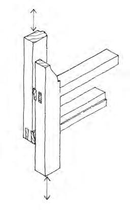
Sash stile with horn (late 19th century onwards) giving stronger joint between stile and meeting rail Meeting rail of upper sash
Sash stile without horn (note dovetailed tenons)
Back lining
Void for pulley weight
Outer lining
Meeting rail of lower sash
Figure 3: Typical vertical sliding sash window: (a) Main components. (b) Cill detail. (c) Detail of junction of upper/lower sash. Illustrations: SPAB


Timber cill Cill board
Wagtail
Pulley stile inner lining Staff bead
Parting bead Glass Cill Sash stile bottom rail
3(b)
SPAB Wood Windows5
Failure of sash joint, breakdown of paint/putty
Breakdown of paint/putty
Breakdown of paint/putty on cill. Defective detail at cill/sash box junction
Shutters fixed in position leading to build-up of moisture in unventilated void
Failure of joint between glazing bar/sash rail.
Breakdown of paint/putty
Failure of joint between sash stile/bottom rail
4(a)
Breakdown of paint. Capillary action between timber and masonry cill. Inadequate fall on cill
Inside Excessive condensation
4(b)
• Condensation persistently forms on the internal surface of the glass.
Wet rot is recognised by slight ripples and discoloration in the paintwork, and the underlying timber is found to be soft and friable when probed. Although the breakdown of the decorative surface of a window is often associated with wet rot, this is not always the case, and a window (or part of a window) should never be condemned on surface appearance alone.
Treatment of wet rot in windows should broadly be as follows:⁵
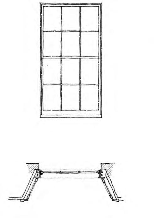
1. Locate and eliminate the sources of moisture.
2. Promote rapid drying of the affected area.
3. Remove decayed timber only as far as is necessary to carry out repairs.
4. In repairs , make use of a species of timber which is known to be durable.
If timber remains in contact with damp masonry - during the period of drying out following removal of the moisture source - consider treating potentially vulnerable areas with a timber preservative; this approach will buy time but should not in most cases be considered as a permanent solution to the problem.

3.3 Dry rot
Dry rot (Serpula lacrymans) occurs mainly in softwoods and is characterised by the affected timber turning a dull brown colour and ‘cubing’ (deep cracks along and across the grain – also found in timber affected by some forms of wet rot). This type of fungus thrives in humid, stable conditions in poorly ventilated voids. As such, it rarely affects windows, but is sometimes found behind sealed shutters and in the pulley boxes of sash windows, especially where there has been an outbreak of the fungus elsewhere in the building.
Treatment of dry rot is more complex than for wet rot and usually should not be tackled without the advice of an independent timber decay consultant.⁶ In tackling dry rot, a primary aim normally is to dry out the structure which has led to the outbreak, and to remove the ‘food’ source, ie the affected timber. Great care must then be taken during reinstatement works to ensure that all new timbers introduced into the building are of
Figure 4: Sash window elevation (a) and plan (b) showing typical areas of decay. Illustrations: SPAB
Figure 5: A sharp instrument is essential for investigating the extent of decay in a window. In this case, rot has occurred following the use of poor quality timber for a past repair.
Photo: Joseph Bispham
SPAB Wood Windows6
a durable type or are pre-treated; and they should be isolated from damp walls/floors, although placing impermeable barriers/ coatings up against timber should be avoided, as this may lead to trapping of moisture in the window joinery.
3.4 Wood-boring insects
Damage caused by wood-boring insects is less common in windows than decay from fungal attack. Many species of wood-boring insects exist, but those chiefly affecting windows are furniture beetle and death watch beetle, with the latter usually only active in hardwoods, especially oak. Beetle activity is recognised by flight holes appearing in the surface of the timber, together with deposits of bore dust. The beetles leave the timber only between March and June, when inspections should take place.
Death watch beetle and furniture beetle are both encouraged by damp timber conditions and, therefore, are often found in association with wet rot. Where evidence of activity is found, treatment should be as for wet rot (see section 3.2); if a timber preservation treatment is used, this should be of a type appropriate to the control of wood-borers.
3.5 Settlement
Movement in masonry or timber-frame walls surrounding a window may lead to deformation of the window with jamming of working parts (sashes, casements) and even the breakage of window glass (see figure 6). Look for obvious signs of general movement within the fabric or more localised movement caused, for example, by the decay of a timber lintel above a window, or where differential movement in the cill and jambs (due to compression in the masonry below the latter) has occurred, giving a bowed appearance to the cill. Any structural movement may require remedial measures and could require the advice of a structural engineer experienced in dealing sensitively with old buildings.⁷ Windows which have become deformed by past movement in a surrounding wall have often been adjusted to suit their realignment, and continue to work effectively.

3.6 General wear and tear
All wood windows require regular maintenance to keep them in working order. Sticking sashes can be eased, although this should be avoided in buildings which have not been in use for some time – with the reintroduction of heat and ventilation, the sashes will often contract slightly, thus working themselves free. Where sashes or casements are loose and allow in excessive draughts, timber fillets may be added to fill gaps or draught strips may be used,⁸ although it is important not to seal windows completely. Windows which have been painted shut should be gently eased and excess paint removed.
Misalignment of sashes/casements may be due to missing or worn beads. If this is the case, the beads should be reworked/refitted or replaced, to allow the window to work properly.
The breakdown of paintwork or putty should be dealt with promptly as this may lead to decay of the timber below.
Figure 6: Structural movement.
Photo: Douglas Kent
SPAB Wood Windows7
4 Work in general
A number of principles should be followed when considering repairs to wood windows:
• Where decayed timber is to be removed to form a splice repair, the minimum amount of existing timber should be removed as is necessary to allow an effective repair to be formed.
• Always work new material to the line of the existing (rather than vice versa) and avoid unnecessary trimming of the original timber. Repairs should follow any existing deformities in the line of the window.
• Generally, avoid mixing timber species between the new and the existing in a repair, as the joint between the two is likely to fail due to differential expansion and contraction during alternating dry and damp conditions.
• When carrying out a repair, try to ensure that the structural integrity of the window is maintained and that the window continues to work as it was designed to do.
• Wherever possible, spliced repairs should be designed to ensure that moisture is directed towards the outer face of the timber and that moisture does not lie on the repair joint. The length of the splice is governed by the section of timber and the nature of the component being repaired, and should be designed to ensure an effective bond between the new and the existing sections of timber.
• Wherever possible, splice repairs should be designed which incorporate mechanical fixings (for example, timber pegs/dowels or non-ferrous screws/pins) as well as glue. Screw or pin fixings should ideally be inserted from the inner face of the window.
• Well-seasoned timber should be used in forming a repair, with the line and density of the grain (number of growth rings) of the new timber matching the existing as closely as possible. As with all joinery work, timber with shakes, fissures, warping, heartwood, sapwood or numerous/large knots should be avoided for use in repair.
• Avoid previous design faults when carrying out repairs. Consider modifying a method of construction (or a previous repair) where it is liable to lead to further decay.
• If possible, repairs to window frames should be formed in situ, especially where the frame is built in and cannot be removed
•
without damaging either the window or the surrounding wall. In general, casements/ sashes can be easily removed without damage, to be repaired on site or in a joiner’s workshop.
Where windows are to be dismantled as part of the repair process, always mark and record the constituent parts before dismantling, especially where a significant number of windows are to be repaired. Similarly, always number glass panes/ quarries before removal.
5 Repairs
5.1 Bottom rail of sash window
The method of repair illustrated in figure 7 allows for the work to be carried out without dismantling the sash. The same procedure for removal and replacement may be used where total renewal of the bottom rail is necessary, although removing the existing decayed rail is easier if a series of vertical cuts are made through the rail before removal.
5.2 Base of sash stile (outer face)
See figure 8.
5.3 Bottom rail/base of sash stile
A similar repair method may be used where the replacement of only the base of the sash stile is necessary, as shown in figure 9.
5.4 Tongue of glazing bar
For replacement of short sections of a glazing bar where only the outer tongue section is decayed, as illustrated in figure 10. If care is taken, this repair can be carried out without dismantling the sash or removing the glass. In most cases, hardwood (for strength and durability) should be used for the new tongue, even where the existing glazing bar is softwood.
5.5 Tongue of glazing bar at junction of bars
See figure 11.
5.6 Glazing bar
See figure 12.
SPAB Wood Windows8
Inside
7(a)
Decay to outer face of bottom rail including tenon
Gently knock down bottom rail after removal of hatched areas of timber of each sash stile
Carefully soften putty and remove glass
Bottom rail and tenon sound
Inner section of stile (including mortice) relatively sound
New outer section of bottom rail glued to existing sound timber
7(b)
Remove or drill out wedges
Cut out hatched area to allow for removal of bottom rail
7(c)
Joint pegged re-wedged and glued
Joint line between new and existing formed on inner side of glazing line and to include full tenon


Figure 7: Bottom rail of sash: (a) Decay. (b) Dismantling. (c) Repair. Illustrations: SPAB


Sloping splice designed to give optimum area of surface to be glued whilst ensuring that moisture is directed away form the glazing line
Joint between new and exisiting timber formed with undercut to direct moisture towards the outer face of the sash stile

Screw fixings from inner faceRe-form anti-capillary drip
Decay limited mainly to outer section of sash stile 8(a) 8(b)
Figure 8: Sash stile (outer face): (a) Decay. (b) Repair. Illustrations: SPAB
SPAB Wood Windows9
9(a)
Dropping of bottom rail relative to stile indicates decay of mortice and/or tenon
11(a)
Splayed splice joint with undercut and step to give optimum surface area for gluing/ fixing and to ensure that moisture is directed away from vulnerable areas towards the outer face of the window

9(b)
New timber chosen to match line and density of existing grain as closely as possible
Figure 9: Bottom rail/base of sash stile: (a) Decay. (b) Repair. Illustrations: SPAB


Inside
10(a)
Inside
10(b)
New putty New tongue glued and pinned into groove cut in existing inner section of glazing bar
Figure 10: Tongue of glazing bar: (a) Decay. (b) Repair. Illustrations: SPAB
Decay largely confined to outer section of horizontal glazing bar
11(b)
New section of timber twisted into position
New section of timber (hardwood) pinned and glued 11(c)
Figure 11: Tongue of glazing bar at junction of bars: (a) Decay. (b) and (c) Repair. Illustrations: SPAB

SPAB Wood Windows10
Splay cut Splay cut
12(a)
12(b)
Cill relatively sound
Decay to foot of outer lining of sash box
14(a)
Decay limited to outer section of existing cill InsideOutside
13(a)
Splayed undercut splice. Alternatively, a simple horizontal undercut splice may be used
Outside
Screw fixings from inner face Step possibly introduced at junction between cill and bottom rail (if not exisiting)


Inside Joint between new and existing timber formed behind line of bottom rail ) or behind line of anti-capillary drip, where this exists)


Cut slot to prevent water being trapped behind bead
14(b)
New outer lining glued to pulley stile and pinned/ screwed adn glued to cill
Rebate at base of cill filled with lime mortar or mastic formed from burnt sand and boiled linseed oil
13(b)
Prime and undercoat base of new cill section before fixing
Figure 12: Glazing bar: (a) Decay. (b) Repair. Illustrations: SPAB
Figure 13: Cill to sash window: (a) Decay. (b) In situ repair. Illustrations: SPAB
Figure 14: Outer lining of sash box: (a) Decay. (b) Repair. Illustrations: SPAB
SPAB Wood Windows11
5.7 In situ repair of cill to sash window
See figure 13.
5.8 Outer lining of sash box
The type of repair depicted in figure 14 can be carried out in situ where the sash box is not situated behind a reveal.
5.9 Base of pulley stile
See figure 15.
5.10 Casement window – general repairs
See figure 16.
5.11 Casement Window – alternative repair to base of jamb or mullion
The type of repair shown in figure 17 is appropriate where the window is performing a load-bearing role and a simple splice repair may not be strong enough. It also ensures that more of the internal face (including mouldings) of the existing mullion is retained than would be the case if the splice illustrated in figure 16 were to be employed.
5.12 Sash and casement mouldings
When replacing a moulded section of timber from an old window, it is very unlikely that a matching size and shape of moulding will be available from a timber merchant. A small section of the original moulding should be carefully stripped of any paint, revealing crisp, clean edges for an accurate mould to be taken. If the end section of the moulding cannot be drawn around, then an accurate moulding section can be obtained using a template former.
Where only small quantities of moulded section are required, it may be uneconomical for a cutter to be made for a spindle moulding machine. If this is the case, a combination of special purpose planes (moulding planes) and a steel scraper shaped to the required finished section can be used. New moulded sections should always be made very slightly over-sized, to allow for working back to the precise line of the existing timber in a repair, so avoiding the need to work the original material.
5.13 Loose joints
Casements or sashes are often in sound condition but the joints have become loose due to the breakdown of glue and loose wedges. The wedges will often be easily removable and will probably be unsuitable for reuse. It may be necessary to remove some panes of glass for the joints to be pulled together successfully.
It should be possible to apply glue to the shoulders of the tenon. This can be achieved by working the glue down to the base of the tenon with a hacksaw blade or piece of card. Glue can then be applied to the voids left by the removal of the wedges from the mortice. The joint should then be pulled together and re-wedged.
Where opening of joints is combined with minor decay such that regluing alone will be inadequate, reinforcement of the timber at the joint can be achieved with a non-ferrous bracket (see figure 18).
5.14 Small areas of decay
If localised pockets of decay are detected in their early stages and the structural integrity of the window remains sound, the defective areas can be scraped out and the remaining, sound, timber treated, filled and, where appropriate, painted.
The treatment can take the form of a timber preservative when using standard modern paints but this is not suitable with all paint types. It is advisable to impregnate timber with raw linseed oil, for example, if using a linseed oil paint.
Larger voids should be filled with a combination of a timber patch (shaped to fill the void) and filler.
Traditional fillers (or ‘stopping’) were formed from a combination of white lead paste and ordinary linseed oil putty sometimes with the addition of chalk, sawdust etc, to give extra volume.⁹ Where linseed putty is used as a filler today, the lead is omitted to overcome toxicity concerns. Of the modern filler types, two-pack systems (for example, epoxy resin or polyurethane type) are generally more durable than ready-to-use fillers.
SPAB Wood Windows12
Remove pocket
Staff bead and parting bead shown removed Decay at base of pully stile below level of pocket
Decayed area of pulley stile removed by cutting saw lines as shown
Where pulley stile is not housed in, a hacksaw blade should be used to cut through nail fixings between linings and pulley stile
15(b)
15(a)
Refix pocket
New section of pulley stile glued and re-wedged to rebate in cill. Outer and inner linings screwed or pinned (nonferrous) to pulley site
15(c)
Figure 15: Base of pulley stile: (a) Dismantling. (b) Cutting back shown on plan of sash box. (c) Repair. Illustrations: SPAB


Horns on head and cill built into masonry
Glazing line for leaded lights
Existing window repaired in situ
Timber peg or non-ferous screw fixings for repair joints
Decayed tenon
Partial decay of cill
Slip tenon
16(b)16(a)
Figure 16: Mullion window: (a) Decay. (b) General repairs. Illustrations: SPAB
Timber peg fixings at exisiting joints
SPAB Wood Windows13
Peg holes draw-bored to ensure a tight fit
6 Glass
6.1 Old glass
The inherent irregularities in handmade crown and cylinder glass found in windows dating from the mid-19th century and earlier contribute much to the liveliness and character of historic buildings. With the invention of drawn sheet glass and later float glass, glazing became much more uniform and dull in appearance.
Figure 17: Mullion window – alternative repair to base of jamb or mullion Illustrations: SPAB

Crown glass is irreplaceable (it is no longer manufactured in large sheets in this country) and is thin and easily broken. Therefore, extreme care should be taken to avoid damage both during general building works (especially involving the erection of scaffolding) and in the repair of individual windows. When considering the method of repair, an assessment must be made beforehand as to the quality of the glass, whether or not it can be easily removed and whether the repairs can be carried out with the glass in situ.
Minor decay and loose joint
18(b)
18(a)
Bracket let into stile and bottom rail (prime recess before fixing bracket)
Non-ferrous bracket with screw fixings
Joint (formed at same angle as underside of bottom rail)
Length of bracket sufficent to gain good fixing into sound timber


Bracket let into (or fixed on surface of) timber on inner face of sash or casement
Non-ferrous bracket with screw fixings
18(c)
Figure 18: Dealing with loose joints. Illustrations: SPAB

If it is necessary to remove the glass for timber repairs, the putty may have deteriorated to such an extent that it can be removed by hand. Otherwise, an organic solvent paint stripper, soldering iron or bespoke infrared lamp can be used to soften the putty. Other methods of softening include the application of household bleach or a mixture of potassium carbonate and quicklime in a 1:3 ratio (by weight). In all cases, extreme care and patience are needed as numerous applications may be required to soften the putty adequately.
6.2 Replacement glass
Replacement glass should be carefully chosen to be compatible with the original glass, but avoiding material which is too reamy (contains noticeable inclusions or inhomogenous glass strings or layers) or over-distorted. In sash windows, replacement glass should be of a thickness (and, hence, a weight) to ensure that the sash is correctly counterbalanced by its weights.
Few sources of new glass are satisfactory for replacement in historic windows. Handmade glass is, however, available from specialist suppliers. Original glass, taken from a window which is decayed beyond repair, should always be kept for reuse in repair work elsewhere within the same building.
Glazing line
SPAB Wood Windows14
6.3 Putty
Reglazing in timber sashes/casements should be carried out in linseed oil putty. The glazing rebates should be primed before applying putty to the appropriate thickness and angle. Where metal fixing sprigs or pins are necessary, these should be fixed with a small gap between sprig and glass to avoid fracturing the thin, delicate glass. Putty should be decorated within a day or two after application to avoid it drying out/shrinking. The paint should be taken slightly over the border, between glass and putty covering about 1 mm of the glass, to form an effective seal against moisture penetration.
Putty thinned with a few drops of raw linseed oil or natural turpentine can be used to seal minor cracks in old putty, thereby extending its life for a few years.
7 Preservatives
7.1 Use
All preservatives have a limited lifespan. They are not a long-term solution to bad detailing or poor quality modern timber, nor are they an alternative to regular maintenance. Some types of timber, such as Douglas fir, do not take preservatives particularly well. Preservatives are also incompatible with certain paints, such as linseed oil paint. If deemed to be useful/ necessary, preservative systems should be carefully selected to ensure compatibility with paints, primers, glues and putty. An applied preservative should be allowed to dry before carrying out repairs, reglazing and re-painting.
Chemically modified timber is available that claims good durability. Its use for repairs is best confined to where the adjacent, existing timber can move independently; for example, for a new cill rather than scarfing in to an old one.
7.1 Methods of treatment
When used in repairs, new timber without a high natural resistance to decay should be pre-treated by the supplier with a doublevacuum treatment using an organic solvent preservative.10 Existing timber components removed from the window for repair can be immersed in a preservative (also organic solvent type), after all the repair cuts have been made. Where window components suffering from decay are to be repaired in situ, removal of the decayed areas of timber can be followed by brushing preservative in multiple applications
or by smothering temporarily the affected area with an absorbent material (for instance, cotton wool) soaked in preservative and covered with polythene sheeting. In all cases, particular attention should be given to treating the end grain of timber.
The use of boron rods (which work by emitting anti-fungal boron when damp) should generally be avoided. Considerable damage (including possible weakening of the joints) is inflicted on the window by the insertion of the rods and they provide protection to only a small area of the wood for a limited period.
8 Pointing
8.1 Lime and burnt sand mastic
The existing pointing material that fills the joint between a frame and the surrounding masonry should normally be matched (taking care not to inadvertently copy inappropriate repair work). The use of haired lime mortar and/or burnt sand mastic (baked sand and boiled linseed oil) is the traditional method for closing the window-to-wall gap. The void behind can be packed with rolled up newspaper, soaked with water before use.
8.2 Modern sealants
Modern mastic sealants and foam fillers should be avoided. They can trap moisture and are disfiguring.
9 Painting
9.1 Deterioration of paintwork
With the exception of some early oak windows, timber windows were usually painted from construction both for aesthetic reasons and to give the timber a protective coating (see figure 19). However, a poor paint specification or badly maintained paint will lead to deterioration in the paint surface, allowing water to penetrate into the body of the timber. This will lead to swelling of the timber, causing further deterioration of the paint finish and a continuation of the cycle of decay.
This problem is best avoided by regular inspection and maintenance of the paint surfaces. Complete stripping of a window is seldom necessary; only loose and defective
SPAB Wood Windows15
areas of paint, putty, filler etc should be removed. Essential stripping of paint can be achieved successfully using an organic solvent stripper, although much patience is required and care should be taken to clean the timber down thoroughly after stripping. Defective paint can also be burnt (flame or hot air stripper) but this method should be avoided on windows in situ (because of the dangers to the general building fabric) or where glass is still in place. Precautions should also be taken when burning off lead-based paint because of the toxic fumes. For the same reason, only wet abrasive paper should be used when rubbing down old paintwork.
9.2 Avoid stripping
Under no circumstances should windows (or any other joinery) be stripped by immersion in caustic soda or similar ‘acid bath’ treatments, as this will deform the timber and weaken the joints.
Drips and anti-capillary grooves with accumulated paint layers should be cleared, and any further repairs carried out before priming. Any reglazing should be carried out after
painting, to minimise the risk of absorption by the timber of the binding oil from the window putty.
Following the removal of paint, all accessible surfaces of the window should be rubbed down (wet abrasive paper) with priming of exposed timber surfaces and application of a minimum of one undercoat and one finish coat. Concealed surfaces of timber (for example, underside of cill, interior of sash boxes) may be coated with primer and undercoat where they are made accessible during the course of repair. Some timber components are left unpainted, to allow the window to function properly (for instance, the junction of the sash window pulley stile/sash stile, which should be waxed to ensure an easy sliding action).

9.3 Choice of paint
Choice of paint is critical to the protection of softwood windows from decay. Leadbased paint systems (including primers) offer excellent durability on most types of wood and are particularly effective for use on partially degraded timber surfaces. However, their use is banned except on exempted buildings.11 Alkyd paint systems are those most generally in use on external joinery. The elasticity required in paints applied to timber surfaces is initially good in alkyd-based paints, but this property deteriorates with age and generally results in the need for repainting much more frequently than with lead-based systems. Alkyd-based primers are not suitable for use on most hardwoods, where a metal-based primer should be used. Some of the linseed oil paints now on the market appear to provide good alternatives to alkyd–based systems.
10 References
For full details of sources cited, see bibliography in Section 11.2.
1 Further guidance on adding secondary glazing is given in Historic England, 2016b, pp50-53
2 See https://www.spab.org.uk/advice/glossary
3 Innocent, 1916, chapter XV
4 Further guidance on recognising the types of fungal decay and wood-boring insect damage encountered in buildings is given in Bravery et al, 2003
5 A leading source of advice on dealing with wood-boring insects and timber-decaying fungi is Brian Ridout’s Timber Decay in Buildings. The approach he sets out is summarised in sections 3.2 to 3.4 of this Technical Advice Note
Figure 19: Windows post-dating the 18th century are commonly made of softwood and require regular redecoration for protection.
Photo: Douglas Kent
SPAB Wood Windows16
6 The SPAB may be able to suggest the names of timber decay consultants who might be contacted
7 The SPAB may be able to suggest the names of structural engineers.
8 See Historic England, 2016a for advice on draught-proofing windows
9 Painting and Decorating, 1947
10 For more on preservative treatment, see Bravery et al, 2003
11 Toxicity concerns mean the supply of lead paint is now restricted by law for use on certain listed buildings (Grades I and II*, or in Scotland Grade A), scheduled monuments and works of art. For more on dealing with lead in painted surfaces, see British Coatings Federation, 2014
11 Other advice
11.1 Contacts
Where work to old windows is being considered, the SPAB may be able to suggest suitable craftspeople, contractors and professionals.
11.2 Further reading
Bravery, A F, Berry, R W, Carey, J K and Cooper, D E (2003) Recognising Wood Rot and Insect Damage in Buildings, 3rd edition, BR 453, Garston: BRE Press
Briggs, M S (1925) A Short History of the Building Crafts, Oxford: Clarendon Press
British Coatings Federation (2014) Lead in Painted Surfaces: Guide on Repainting and Removal for DIY and Professional Painters and Decorators, HS 022, rev 5, Coventry: BCF. Available at: https://www.coatings.org.uk/faq/Removing_ old_lead_paint-15.aspx (Accessed 20 June 2019)
English Heritage (2011) Glass and Glazing, Practical Building Conservation, Farnham: Ashgate Publishing Ltd
English Heritage (2012) Timber, Practical Building Conservation, Farnham: Ashgate Publishing Ltd
Historic England (2016a) Energy Efficiency and Historic Buildings: Draught-Proofing Windows and Doors, v1.1, London and Swindon: Historic England. Available at: https://historicengland.org.uk/images-books/ publications/eehb-draught-proofing-windowsdoors/ (Accessed 20 June 2019)
Historic England (2016b) Energy Efficiency and Historic Buildings: Secondary Glazing for Windows, v1.1, London and Swindon: Historic
England. Available at: https://historicengland.org.uk/images-books/ publications/eehb-secondary-glazingwindows/ (Accessed 20 June 2019)
Historic England (2017) Traditional Windows: Their Care, Repair and Upgrading, London and Swindon: Historic England. Available at: https://historicengland.org.uk/images-books/ publications/traditional-windows-care-repairupgrading/ (Accessed 20 June 2019)
Innocent, C F (1916) The Development of English Building Construction, Cambridge: Cambridge University Press. Reprint 1999, Shaftesbury: Donhead Publishing Ltd
Painting and Decorating (1947) Home Mechanic Series, London: A Arthur Pearson Ltd
Ridout, B (2015) Timber Decay in Buildings and its Treatment, Broome: Scientific and Educational Services Ltd. Available to purchase from the SPAB
Tutton, M and Hirst, E (eds) (2007) Windows: History, Repair and Conservation, Shaftesbury: Donhead Publishing Ltd
Wood, C, Bordass, B and Baker, P (2009) Research into the Thermal Performance of Traditional Windows: Timber Sash Windows, Research Report 109/2009, London: English Heritage. Available at: https://research.historicengland.org.uk/Report. aspx?i=16035 (Accessed 20 June 2019)
11.3 Other organisations
Brooking Museum of Architectural Detail www.thebrooking.org.uk
The museum displays items from the Brooking National Collection. This is an unrivalled assemblage of British windows and other architectural elements spanning many centuries
11.4 Use of timber preservatives
Information on currently approved timber preservatives can be obtained from the Health and Safety Executive at www.hse.gov.uk .
Before using any timber preservative, carry out an assessment in accordance with the Control of Substances Hazardous to Health (COSHH) Regulations 2002 (as amended). You are strongly advised to consult the following publication before specifying and using timber preservatives:
Department for Environment, Food and Rural Affairs, the Health and Safety Commission and the National Assembly for Wales Environment, Planning and Countryside Department (2006) Pesticides: Code of Practice for Using Plant Protection Products, London: Department for Environment, Food and Rural Affairs
SPAB Wood Windows17
The content of this publication is offered in good faith, but neither the authors nor the Society can accept responsibility arising from incorrect or incomplete information that may be included. The use of traditional materials may incur risks that are different from those associated with modern materials. Manufacturers’ and suppliers’ guidelines should always be observed. This document is intended as a contribution to a continuing debate and we welcome comments.
Written by Andrew Townsend and Martyn Clarke. This publication revises and supersedes our former Technical Pamphlets 13 (1st edition, 1992 and 2nd edition, 1998). The authors are indebted to Dr Joseph Bispham for his help with the preparation of this revised edition. Grateful thanks to Judith Rodden for editorial advice. Produced by Catherine Peacock. The sources of illustrations are given adjacent to them together with any copyright where not belonging to the SPAB.
The acknowledgements for help and advice with the first edition of this publication are also still relevant and go to Robert Franklin and members of the SPAB Technical Panel, especially Paul Bedford and Philip Hughes.
The Society for the Protection of Ancient Buildings (SPAB) believes old buildings have a future. From cottages to castles and from churches to cathedrals we are here to help buildings and the people who care for them. Through our unique training schemes, courses, advice and research we help people put our expertise into practice.
Today the SPAB encourages excellence in repair and good new design to enrich and complement the built historic environment. We train new generations of architectural professionals and building craftspeople to conserve this landscape with sensitivity and skill, and we play a statutory role as adviser to local planning authorities. In our casework we campaign actively to protect old buildings at risk.
SPAB: hands on history. Join today to support our positive, practical approach to building conservation.
Published by the SPAB in December 2019

© SPAB 2019 Edn 3 Rev 0
SPAB ref T5303M www.spab.org.uk
ISBN 978-1-898856-44-3
The Society for the Protection of Ancient Buildings
37 Spital Square, London E1 6DY Tel 020 7377 1644 info@spab.org.uk www.spab.org.uk
A charitable company limited by guarantee registered in England and Wales Company No 5743962 Charity No 111 3753 VAT No 577 4276 02
Patching Old Floorboards

SPAB Technical Advice Note
Philip Hughes BSc, MRICS (Chartered Building Surveyor) and SPAB Scholar
The Society for the Protection of Ancient Buildings
37 Spital Square London E1 6DY 020 7377 1644 info@spab.org.uk www.spab.org.uk
Contents
An old floor of wide boards – scrubbed or polished for generations and uneven from wear – adds considerable richness to any room in an old building. A floor is one of the principal surfaces of a room, yet ancient boards are often badly abused. Bodged attempts to replace boards are common. Even when replacement is completed satisfactorily, the result will not always be visually acceptable. In addition, replacement of floors in their entirety often takes place unnecessarily.
This Technical Advice Note aims to alleviate the problem by suggesting a number of methods by which old boards may be patched or repaired.
1 Introduction
3
2 Deterioration 3
3 Lifting floorboards
3
4 Undulations and gaps 5
5
Reducing unevenness
6
6 Repairing a split board 6
7 Repairing a broken edge
7
8 Strengthening a weak board 8
9 Splicing a broken end
10 Relaying old boards
11 Surface treatment
12 Conclusion
13 References
14
Other advice
Cover image: Warmth and richness of a well-repaired old floor.
Photo: Philip Hughes
8
8
9
9
9
9
SPAB Patching Old Floorboards2
.......................
.......................
.......................
.......................
.......................
.......................
.......................
.......................
.......................
.......................
1 Introduction
This Technical Advice Note explains common reasons why floorboards deteriorate (section 2) and a range of methods by which they can be repaired (sections 4 to 9). It also discusses techniques for successfully lifting floorboards, where it is necessary to take them up, and offers advice on their relaying (sections 3 and 10) and surface treatment (section 11).
The Advice Note is written with butt-edged boards in mind and the guidance given will not necessarily be suitable for tongued-andgrooved boards. The ancient method of fixing boards to the joists was with wooden pegs and where these or any other unusual features are found, specialist advice should be sought.
Technical terms used in this guidance are defined in our online glossary.1
2 Deterioration
A full examination of causes is outside the scope of this Advice Note, but the principal areas include:
• Beetle attack.
• Fungal decay.
• Careless lifting of weakened boards, particularly by electricians, plumbers and heating engineers (see figures 1(a) and (b)).
• Natural seasoning, shrinkage, and warping of boards original laid ‘green’.
• The effects of furniture (especially castors) when positioned on the edge of an old board (see figure 1(c)).
It is relatively unusual to find that boards affected in any of the above ways are beyond repair (see figure 1(d)). For example, although a board may be suffering from beetle attack and have many ‘worm holes’ (actually beetle ‘flight’ holes) its strength may not have been reduced significantly.
In such a case, treatment against beetle attack may be all that is necessary.2
3 Lifting floorboards
It is extremely easy to cause serious damage to floorboards by attempting to lift them –particularly when the board is decayed. Despite the pitfalls, there are numerous techniques for lifting floorboards successfully. Lifting the first board without damage is usually much more difficult than removing the remainder. It is not an operation which should be rushed into –it requires ingenuity, preparation, care and patience! If there is an opportunity to choose which board to lift first, select with care. The ideal is a shortish board, with at least one end in relatively good condition, not placed against a wall, and preferably with a gap big enough for the bolster to fit between boards.
The necessary tools are likely to include: a wide-bladed bolster (preferably two of these); wooden blocks of various thicknesses; a flat hardened steel plate; a hammer; a 13 mm (½”) batten about 200 mm (8”) longer than the width of the board; nail punches; a hacksaw; and a crowbar.
1. Using a block of wood (or the steel plate) to protect the edge of the adjoining board, work around the board to be lifted with the bolster, levering from side to side slightly, to try to loosen the board (see figure 2(a))
2. Starting over a joist (by a nail) about a third of the way down the board (to avoid splitting the end), lever more vigorously with a pumping action first one side of the board and then the other, so as to raise the board by up to one-third of its thickness. Ensure the edge of the adjacent board is protected. Moving towards the middle, then back towards the end, repeat the process until one end of the board comes free. If this does not seem to be working or if the board is very decayed, resort to a nail punch and try to drive the nails down.
3. When one end has been freed, try placing the 13 mm (½”) batten underneath it, spanning the two adjacent boards, and gradually move this towards the next set of nails with gentle pressure applied on the free part of the board (see figure 2(b)). The amount of pressure will depend on the condition of the board. This will normally ease the nails slightly out of the joists. Remove the batten and allow the board to drop to its original position to give access to the nail heads. If this does not succeed, try the bolster again or perhaps the crowbar
SPAB Patching Old Floorboards3

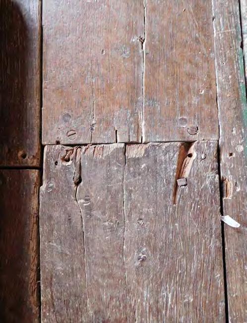

 Figure 1: Damage to boards caused by: (a) and (b) Careless lifting and relaying during installation of central heating and wiring runs. (c) A castor, which can be particularly serious when the castor is positioned over the edge of a board. Softwood boards have been used inappropriately in (d) to replace a damaged wide elm board – could it have not been repaired? Photos: Philip Hughes
SPAB Patching Old Floorboards4
1(b)1(a) 1(c) 1(d)
– levering (pump action again) under the board near the position of the nail, but away from the edge of the board.

4. Particular care needs to be taken with the nails at the end of the board, as it is easy to split an old board unless these are removed gently.
5. Once the board is free, pull out the nails –pincers, hammer or crowbar.
The levering process using the bolster against the side of the board is probably the one most likely to cause damage by bruising neighbouring boards or splitting away part of the board being lifted. This process can usually be avoided when lifting the second and subsequent boards as it is possible to place a block across the joists and to lever against the underside of the board with a crowbar (see figure 2(c)). Once the board has started to lift, the bolster or crowbar can be inserted between board and joist and levering with a pumping action resumed. Again, it is wise to start about one-third of the way along a board and work to the middle and back to the end.


Where a board (or part) is very fragile, it may be necessary to cut the nails using a hacksaw.
Ingenuity and care are the keys to success.
4 Undulations and gaps
It is sometimes suggested that all the floorboards should be lifted in order to shuffle them up to close gaps or to level a sloping or undulating floor. In general, such proposals should be resisted for various reasons unless there is a special need, for example, to carry out repairs. In particular, there is a danger that lifting floorboards will cause damage. Also, the undersides of many old boards are shaped because either the board or the joists are uneven, and in such circumstances they must be replaced in their original position exactly.
Deflection in a floor is often reflected by movement elsewhere in the structure, but provided that the structure is still sound it may be best to leave well alone. A levelled floor can look extremely out of place in an old cottage or house where the walls, windows and doors have deflected and where the ceiling slopes at an angle similar to that of the old floor.
Gaps between boards must be expected in an old house. Normally these will be unobtrusive and cause little problem, but where gaps approach 5 mm (¼”) or more it may be worth considering the introduction of slips of matching timber between the boards (see figure 3). This will, of course, avoid the need to lift and possibly damage the old boards. Papier mâché is also sometimes used to fill gaps between boards.
Extent of levering action for normal butt-jointed boards with slight gaps between
Block of wood to protect edge of board
Crowbar
Block across joists

Batten
Block to protect underside of board. Essential if board is weak. If necessary, the block can be clamped in position
2(b) 2(c)
Figure 2: Lifting butt-edged floorboards: (a) The first stage. (b) Easing up the first board. (c) Lifting second and subsequent boards.
Illustrations: Philip Hughes
Bolster Pressure
SPAB Patching Old Floorboards5
5 Reducing unevenness
An uneven board can rarely be made perfectly straight, but any twist or warp can usually be reduced to acceptable levels:
1. Lift the board.
2. Either steam the board or immerse and soak it in water. (Note: This is likely to spoil any finishes which have been applied to the board.)
3. Lay the board out to dry on battens and apply weights to overcome twisting. There is a tendency for boards to revert partially to the original twist when the weights are removed, and this should be compensated for by overweighting.
4. Allow the board to dry slowly whilst under pressure for at least one week.
5. If serious warping is still present, try applying wet rags to selected areas of the board and re-weighting. The dampened areas will swell slightly – helping to straighten a board. If it is held flat while drying, then the warping is likely to be reduced. The process can be repeated.

6. Treat the underside of the board (and joists etc, if necessary) against beetle attack.
7. Relay the old board.
6 Repairing a split board
Option 1:
1. Clean out the crack/split.
2. Work glue into the split.
3. Insert wedges in joints either side to close the split while the glue is drying.
4. Insert a butterfly stitch across the crack (if required).
Option 2:
1. Lift the board.
2. Mark the joist position on the board.
3. Clean out the crack.
4. Remove warp/twist (if necessary).
5. Glue and clamp. Ensure use of blocks to protect the edges, and that the board remains true.
6. Treat the underside of the board and the joists etc, if necessary.
7. Screw on fixing blocks but do not glue (see figure 4). If the split has been caused by maltreating the board, ensure the blocks are of similar timber to the board, wellseasoned and with grain running in same direction as that of the board. If a split has been caused by natural movement of the timber, the blocks should be fixed with slotted screw holes and with the grain running across the board.

8. Relay the board.
Joist positions marked on underside of board
Blocks to protectJoist positions marked on underside of board edges of board crack glued
Block of same timber as board. See note 7 above for fixing details
Figure 3: Gap between floorboards filled with slip of matching timber. Photo: Philip Hughes
Figure 4: Repairing a split board. Illustration: Philip Hughes
SPAB Patching Old Floorboards6
7 Repairing a broken edge
1. Choose the repair type (see figures 5 and 6).
2. Lift the board (if necessary) and mark joist positions on the underside of the board.
3. Select seasoned timber of the same variety and match the grain.
4. Cut out around the broken edge of the board.
5. Form a new section to fit the old, glue and clamp in position.
6. Carefully pare down the new section to follow the undulations of the old. Do not pare down the surface or the edges of the old board.

7. Treat the underside of the board and joists etc, if necessary.
8. Relay the board (if lifted previously).
Grain of block runs in same direction as board
Note: this type of splice is fairly weak but can be useful for boards at edges of floors - particularly for making good holes left by pipes etc

6(b)
loose tongue
Figure 6: Repairing a broken edge: (a) Dovetail slice with ends supported on joists. (b) Dovetail splice supported on block screwed to underside of board. (c) Tapered splices. (d) Corner insert.


Illustrations: Philip Hughes
 Figure 5: Patches of same timber variety and matching grain. Photo: Philip Hughes
SPAB Patching Old Floorboards7
----- 7 / / / 6(a)
6(c) 6(d)
8 Strengthening a weak board
1. Lift the board (if necessary).
2. Screw battens to the sides of the joists over the area affected.
3. Lay 25 mm thick slats on battens under the weakened board (see figure 7).


4. Treat the board, slats and battens against beetle attack. Note: Treatment must be undertaken before any wax is applied.
5. Impregnate weakened areas of the board with beeswax. (If the board has become extremely fragile, it may be necessary to use resins.)
6. Relay the board.
Note: It may be necessary to strengthen or fill some areas with wood glue and sawdust – for example, around nail holes.
9 Splicing a broken end
If the end of a board is so decayed that it cannot be saved, then it is usual for the board to be cut back to the next joist and a short board pieced in. However, this can often mean that much more of a board is removed than is strictly necessary and, in some floors, a new short board can look completely out of place. In such circumstances it may be appropriate to splice a new end on to a board. The most appropriate type of splice to use will depend on a number of factors including the grain of the wood and the width of the board. Billiard cue jointing is sometimes used but two simpler types of splice joint are illustrated (see figure 8).
10 Relaying old boards
Considerable care needs to be taken when relaying old floorboards. In general it is easier to nail floorboards down, but there are a number of occasions when this should be avoided, and screws used instead. For example:
1. Over a decorative plaster ceiling or ceiling painting, which might be disturbed by nailing.
2. Over a lath and plaster or reed and plaster ceiling where the plaster key is suspect.
3. Over service runs etc, where frequent lifting and relaying of the board will be necessary.
Iron screws will eventually rust and become extremely difficult to remove (even if greased). In general, brass screws should be used and these should be lightly greased before fitting to aid removal. Where a board is likely to be lifted and relaid every few years (for example, over service runs), brass cups should be used to protect the board from any damage caused by the screw head.
Glued joint
25 mm slats
Battens screwed to sides of joists
Figure 7: Giving additional support to a weak board.
Illustration: Philip Hughes
25 mm supporting slats Batten screwed to joist
Batten screwed to joist to support end of old board
Figure 8: Splicing the end of a board at the edge of a floor (a) and (b).

Illustration: Philip Hughes 8(b) 8(a)
Glued joint

SPAB Patching Old Floorboards8
Where walls may be damp, keep the edge board slightly away from the wall to reduce the risk of decay.
Avoid placing fixings under the front edge of any skirting. This avoids the need for the skirting to be disturbed if the board needs to be lifted again.
11 Surface treatment
This is really a suitable subject for an Advice Note on its own, but it is perhaps worth mentioning a few points here.
Old boards should never be sanded. If a board has suffered at all from beetle attack, sanding will remove the smooth surface of the board and leave a ragged mess of ‘worm-ridden’ timber beneath.
If it is necessary to remove a paint, stain or varnish on the surface of the board, reference should be made to SPAB Information Sheet 5 on Removing Paint from Old Buildings. 3 Stains will have soaked into the surface of the timber, and although poulticing may reduce the effect of the stain, it is unlikely to remove it entirely. Repeated poulticing may help.
In general, old boards that have not been polished will have been scrubbed. Minimum water should be used when scrubbing boards. If the board has suffered from beetle attack in the past, scrubbing may remove the surface in the same way as sanding. In such cases, it is probably best to treat the board with timber preservative and then polish with beeswax – trying to get this to soak into the board to consolidate the weakened timber surface.
Before polishing boards, thought should be given to the serious danger of slipping. Loose rugs should never be laid over polished floors.
Modern varnishes and finishes should be avoided, as they tend to give an unsympathetic appearance. Linseed oil should also be avoided as it is slightly sticky, attracts the dirt and darkens with age.
12 Conclusion
As one of the principal surfaces of a room, the overall treatment of a floor needs to be carefully considered in relation to: the appearance of the room as a whole; the context of the building; and the function of the floor. Simple straightforward repair of existing floorboards, as described in this Technical Advice Note, should substantially enhance the quality and appearance of the interior of the building. When repairs have been well-executed, there should not normally be any need to try to tone them in, as they will demonstrate the care and craftsmanship that has been lavished on the building.
13 References
1 See https://www.spab.org.uk/advice/glossary
2 For more about dealing with timber decay, see SPAB Information Sheet 14 by Richard Oxley on Is Timber Treatment Always Necessary? An Introduction for Homeowners
3 For more about paint stripping, see SPAB Information Sheet 5 by Adela Wright on Removing Paint from Old Buildings
14 Other advice
14.1 Contacts
Where work to old floorboards is being considered, the SPAB may be able to suggest suitable specialists, including contractors.
14.2 Further reading
English Heritage (2012) Timber, Practical Building Conservation, Farnham: Ashgate Publishing Ltd
Oxley, R (1999) Is Timber Treatment Always Necessary? An Introduction for Homeowners, SPAB Information Sheet 14, London: Society for the Protection of Ancient Buildings
Schofield, J (1997) Beeswax Polish, SPAB Information Sheet 13, London: Society for the Protection of Ancient Buildings
Slocombe, M (2017) The SPAB Approach to the Conservation and Repair of Old Buildings, London: Society for the Protection of Ancient Buildings
SPAB Patching Old Floorboards9
The content of this publication is offered in good faith, but neither the author nor the Society can accept responsibility arising from incorrect or incomplete information that may be included. The use of traditional materials may incur risks that are different from those associated with modern materials. Manufacturers’ and suppliers’ guidelines should always be observed. This document is intended as a contribution to a continuing debate and we welcome comments.
Written by Philip Hughes. This publication revises and supersedes our former Information Sheet 10 (1st edition, 1988). The author is indebted to Dr Joseph Bispham and Ben Hornberger for their help with the preparation of this revised edition. Grateful thanks to Judith Rodden for editorial advice. Produced by Catherine Peacock. The sources of illustrations are given adjacent to them together with any copyright where not belonging to the SPAB.
The Society for the Protection of Ancient Buildings (SPAB) believes old buildings have a future. From cottages to castles and from churches to cathedrals we are here to help buildings and the people who care for them. Through our unique training schemes, courses, advice and research we help people put our expertise into practice.
Today the SPAB encourages excellence in new repair and good design to enrich and complement the built historic environment. We train new generations of architectural professionals and building craftspeople to conserve this landscape with sensitivity and skill, and we play a statutory role as adviser to local planning authorities. In our casework we campaign actively to protect old buildings at risk.
SPAB: hands on history. Join today to support our positive, practical approach to building conservation.
Published by the SPAB in October 2019
© SPAB 2019 Edn 2 Rev 0
SPAB ref T5302M www.spab.org.uk
ISBN 978-1-898856-38-2
The Society for the Protection of Ancient Buildings 37 Spital Square, London E1 6DY Tel 020 7377 1644 info@spab.org.uk www.spab.org.uk
A charitable company limited by guarantee registered in England and Wales Company No 5743962 Charity No 111 3753 VAT No 577 4276 02
Caring for old floors


Advice from the SPAB


History at Your Feet: the care & repair of old floors 3 Introduction 4 Damp-proof membranes & solid floors 4-5 Floor waxes & old floors 6-7 Timber floors 8-10 Natural stone floors 11-13 Marble 14 Floor tiles 15-16 Brick floors 17 Plaster floors 18 Excessive salt efflorescence 19 Chalk floors 19 Earth floors 19 The SPAB’s top tips for old floors 20 Contents Reproduction of this publication’s content in whole or part is prohibited without prior written permission of the SPAB. Copyright 2016 SPAB. This downloadable booklet is a version of the SPAB’s Technical Pamphlet ‘The Care and Repair of Old Floors’ by Adela Wright. Images,toptobottom:woodenfloorattheOldPostOfficeinTintagel,Cornwall(KateGriffin),CanonsAshbykitchenwithElizabethan flagstonefloor(NationalTrustImages/AndreasvonEinsiedel),tiledflooratStDavid’sCathedralinWales(KateGriffin),brickflooratStMary’s Cawston,Norfolk(SPAB). The Society for the Protection of Ancient Buildings 37 Spital Square, London, E1 6DY, 020 7377 1644 www.spab.org.uk info@spab.org.uk twitter.com/@SPAB1877 facebook.com/SPAB1877 A charitable company limited by guarantee registered in England and Wales. Company number 5743962. Charity number 1113753. Scottish charity number SCO39244
History at your feet: care and repair of old floors

The SPAB (Society for the Protection of Ancient Buildings) is Britain’s oldest heritage organisation. Co-founded by William Morris and Philip Webb in 1877, today it is a campaigning charity offering informed practical advice and assistance to owners of older buildings and those who work with them. The SPAB has members in all parts of the country and active regional groups. If you find the following information helpful, why not consider becoming a member to help us spread the message of gentle conservation.
This pamphlet (based on an original SPAB document written by Adela Wright, RIBA) has been produced as part of the SPAB’s History at Your Feet campaign to make people aware of the importance of old, original floors.
The SPAB believes that floors contribute enormously to the ‘spirit’ of a place. The patina of time caused by centuries of wear and tear, daily use and gradual settlement are essential components of a space’s presence and unique atmosphere. The floors of old buildings are often worn, discoloured, and out of true level. Yet these imperfections can make their own important contribution to the interest, beauty and historic value of a structure.
Floors are where we make a direct physical connection to a space, following in the footsteps of those who – throughout the centuries – have gone before us. The grooves, undulations, imperfections and scratches are the ‘ghosts of time’. The SPAB believes that once you make a significant intervention to an old floor you remove something vital to a building’s heart and story.
Yet obliteration of ancient fabric is happening with alarming frequency. Work is undertaken under the guise of ‘improvement’ with little or no regard given to the aesthetic or historic value of a floor and its importance to the integrity of a building or place.
The SPAB fears that a vital ‘step’ is being missed by homeowners, architects, builders and planners who, often unwittingly, proceed without first taking note of the significance of the materials, literally, beneath their feet. Any decision to replace them, apply surface treatments, or alter their levels should not be taken without careful consideration, particularly as most old floors are not difficult to maintain.
Bannerimage:VictoriantilesatStDavid’sCathedralinWales.Credit:Kate Griffin.
3
Introduction to caring for old floors
The primary aim in caring for an old floor should be to maintain its appearance and prolong its life. Strange as it might sound, the ‘do nothing’ option has a track record of being cheap, pragmatic and effective in the long term and should not be ignored.
• Surface soiling should be removed before it becomes impacted
• Moisture should be controlled
• Aggressive chemicals, seals and other inappropriate coating should avoided
Alterations to floors in an old building may require Listed Building Consent and anyone thinking of alterations or major work should contact their local conservation officer for advice.
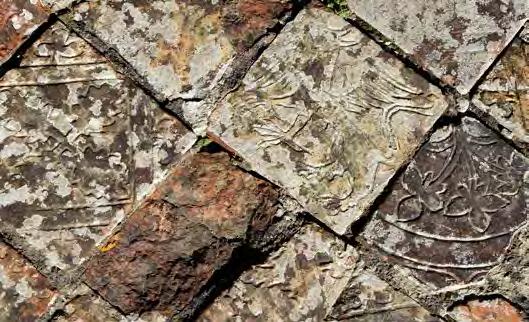

can be solved by inserting a damp-proof membrane (DPM) under the existing floor covering. This solution is commonly suggested because standard practice in the construction of a new building is to include a membrane within the floor thickness which is linked to a horizontal damp-proof course (DPC) designed to prevent moisture rising within the thickness of the walls, inside or outside.
DA MP PROOF MEMBRANES AND SOLID FLOORS
Advice is often given that damp problems in old floors at ground or basement level
However, in an old house lifting and then relaying an old floor on a new DPM can cause more problems than it solves. Restricting the amount of moisture that can evaporate through the floor may adversely affect the moisture content at the base of previously dry walls, partitions and chimney breasts. This is because the introduction of a horizontal membrane can displace and concentrate moisture – now unable to evaporate over the whole surface – to the edges. Many old walls at the edge of DPMs can seldom be effectively treated retrospectively against rising dampness. Particular problems occur in very thick walls, walls without regular coursing, ungrouped rubble-covered walls and walls built of earth, clay, chalk or flint. The SPAB rarely endorses the insertion of DPMs and DPCs in older, traditionally constructed properties, both because of the potential
Bannerimage:BristolCathedral.Left:StrataFlorida,Ceredigion,Wales.Credit: KateGriffin.
4
of damage to historic fabric and because intervention is usually unnecessary.
The SPAB’s experience is that many dampness problems are related directly to construction defects or interventions, which have undermined the previous breathing potential of the floor or rooms. Initially, with any dampness related problems, thought should be given to common potential problems: faulty guttering, downpipes and drains; external ground levels; adequacy of ventilation and mis-diagnosis of condensation as rising dampness, and the use of rubber-backed wall-to-wall carpets which have acted as a membrane and held moisture back. In the last case, and also after constructional defects have been resolved it may take some time for the floor to dry. The testing of drains and soakaways to establish where they run and their condition is also important.
floor which can be difficult to remove. In addition, a concrete floor and DPM can prevent moisture caused by spillage or floor washing from draining away or being absorbed naturally into the ground.
Improving site drainage around exterior walls will sometimes help to alleviate conditions caused by a high watertable by reducing the moisture content immediately adjacent to building fabric and thus avoid the need to disturb a floor. Old floors have often survived well due to a stable environment. The humidity within some flooring materials, such as stone, brick, chalk and limewash, if left undisturbed, may vary according to the weather and a little damp can often be an asset as it may help prevent ‘dusting’ of the surface. Old floors must be allowed to ‘breathe’, preferably downwards as well as upwards.

The environmental changes caused by re-laying old brick, stone or tiled flooring above a new membrane can affect the appearance and durability of the floor. Salt contamination, in the form of a white sediment, originally absorbed from subsoil, may migrate to the surface. These salts may, in turn, absorb moisture from the air and create a damp floor. Regular brushing may become necessary to reduce the deposit. There are also cases where residue of cement, from a newly laid cement screed above a DPM have migrated to form an unacceptable film on the surface of an old
If all other solutions have been tried and have failed and the decision is taken to lift and relay the old flooring on a concrete slab, great care should be taken as it should be recognised that damage to the original materials is likely to occur. If insulation is to be laid it may help to reduce condensation but the material should be carefully chosen to ensure moisture decay resistance and sufficient compressive strength. In certain projects the whole floor has been photographed and drawn with each slab numbered and stone type noted. Only after this was the floor lifted. The floors are often subsequently re-laid on a sand-lime base to allow water trapped in the new concrete slab to evaporate and each stone is re-laid in its original location.
Imageleft- ablockeddownpipeatAlbrightonStMary.Credit:SPAB.
5
Floor waxes and old floors
Polish will help to protect a surface from grit, grime, water and stains. But a heavy buildup of polish will inhibit the floor’s ability to ‘breath’ which can hasten decay. It will also increase the risk of slipping. Highly polished surfaces, and those which seal the surface, were rare before the 19th century. The term floor wax covers a wide range of both natural and synthetic materials. The three main types in used today can be classified as:
• Traditional solvent-based floor wax
• Proprietary solvent-based floor wax
• Water-based emulsion floor wax
Most are available in liquid or paste form.
T RADITIONAL AND SOLVENT BASED FLOOR WAx ES
These are made from beeswax and turpentine, and retain their flexibility, allowing a floor to breathe and any moisture present to evaporate. Early polishes consisted of pure beeswax melted with hot irons or in a bain marie, to ease application. The addition of turpentine dissolves the wax and dispenses with the need to soften by heating.

Tins of beeswax and pure turpentine polish are now available widely. (If you are interested in finding out how about homemade polish SPAB Information Sheet 13
Beeswax Polish gives you a step-by-step guide). This traditional polish can be used on all types of wood and is particularly suitable for open-grained wood such as oak and pine (also used for furniture and panelling). It feeds timber and will prevent excessive dryness. Thin coats can also be applied to timber floors and some other natural types of flooring, such as stone flags. In all situations where a new finish is to be applied a test should be carried out first on the material to which it is to be applied.
A PPLICATION OF BEESWAx AND T u RPENTINE POLISH
Polish should be applied rarely and sparingly but frequent dry buffing will help to protect the floor and keep the surface free from dirt. Once an acceptable coat has been established a further overall coat may only be necessary about once a year. New applications should be restricted to areas subject to use and wear to avoid a build up of wax elsewhere on the floor. Excessive wax can trap dirt, darken floors and form a slippery surface.
Application is with a soft cloth, brush or electric polisher. Warming the polish eases the operation and helps to force the wax into crevices. Adequate ventilation will help to dry the polish.
Banner image: Avon Tyrell, Hampshire. Credit: SPAB.
6
A liquid polish can be used for cleaning a waxed floor prior to adding extra polish to an existing polished surface. On the rare occasions when it is necessary to remove existing polish, white spirit can be used.
P ROPRIETARY SOLVENT BASED FLOOR WAx ES
These are made from synthetic materials, using waxes such as paraffin dissolved in solvents such as white spirit. Most of these waxes are derived from petroleum and contain additives such as silicone, designed to increase water repellency qualities and to form a hard glossy finish. As a result the breathability qualities of an old floor are impaired and the non-slip advantages of using a traditional polish may be reduced. The deterioration and ‘wearing’ qualities of these polishes can be unattractive and the polishes are often difficult to remove.
Solvent vapour, i.e. from white spirit and to a lesser extent turpentine, constitutes a health hazard. Ample ventilation should be provided during application. Solvents also pose a fire risk.
WATER BASED EM u LSION FLOOR WAx ES
The solvents in solvent-based floor waxes can dissolve certain 20th century synthetic floor finishes and as a result many types of water-based emulsion waxes were developed from the second quarter of the 20th century. These now satisfy the needs of most new flooring materials. They contain emulsified resins and polymers. The early waxes, such as carnauba in water emulsion polishes, have now been largely replaced by materials of synthetic origin although they are still classified as ‘wax’.
The aim of manufacturers now is to develop a product with an increased or instant
gloss on drying, thus reducing the need for manual polishing and buffing. The coatings are effective on most modern synthetic floorings. They provide a hard surface, are easy to maintain and are non-flammable.
These types of floor waxes are designed for floors that are absolutely dry and laid above a concrete sub-floor with a dampproof membrane. They are not suitable for finishing old flooring materials or for floors that have been treated with solvent-based polishes as any traces of remaining wax will affect the efficiency of the water emulsion coating.
Water-based emulsions can introduce moisture into old floors with damaging results. They mad raise the grain and introduce dirt into timber. Their use to ‘seal’ timber is controversial. Seals can break down in areas of heavy traffic, such as doorways, which may result in staining.
7
Timber floors
Medieval floorboards were predominantly oak, and were riven, axed, or pit-swan in widths of up to 450mm or more, which varied in a single floor. The boards tended to be laid parallel to, and rebated into, the upper edges of heavy floor joists which were laid flat (i.e. contrary to the later practice of ‘joists on edge’). Elm boards, typically 300mm wide, were common in the 17th century and softwood came into general use in the 18th century, a time when floors began to be wholly or partly carpeted. Tongues and grooved boards appeared in the 1820s.


The value of old floor boards is not always recognised. Whole planks are often replaced where it would be possible and much less destructive to piece-in sections of the same species of wood, matching the grain. Where a boarded floor is of historic interest, but is beyond repair, new boards can sometimes be laid above the old as a means of retaining the original floor as part of the archaeology of the building. However, careful thought needs to be given as to how the new floor level will affect adjacent architectural features such as doors, skirtings, architraves, thresholds, hearth stones etc.
Some timber floors slope and creak. These ‘defects’ often occurred at an early date and may have adapted to movement in a
building that has long since stabilised. But the following defects could be a cause for concern:
• Structural failure due to the removal of posts of par titions of lower floors.
• Inadequately supported joists
• Insect attack and rot, particularly in beam ends embedded in walls.
Old floor boards can be repaired insitu but salvaged boards, that have become distorted, can rarely be forced back into position if replaced on new or repaired joists. Warped boards can seldom be reversed. A sloping floor that has reached an uncomfortable state can sometimes be improved by fixing tapered firring pieces to the top face of existing joists.
Images:Banner-ChastletonHouse,LongGallery.CreditNationalTrustImages/ NadiaMacKenzie.Above-OldPostOffice,Tintagel,Cornwall.CreditKate Griffin.
8
This may enable boards that have not become too distorted to be re-laid nearer to level.
Squeaking floorboards may be caused by one board rubbing against another or by loose boards. The problem can sometimes be alleviated by inserting a screw through boards where they pass over joists. The use of screws for this purpose should be limited to the minimum necessary as they can be visually obtrusive. The use of timber plugs or pellets can reduce the visual impact of screws but can make lifting at a later date more difficult.
Early ground floor boarded floors were often laid to rough joists laid directly on earth or over older floors of plaster, brick or stone, often one above the other, an arrangement that could encourage decay due to excessive dampness. Later boarded floors were laid on joists supported above the ground on brick piers or sleepers walls leaving a void usually with provision for ventilation at the perimeter. It is important to ensure that air bricks or other means of venting such voids are kept free of rubble, earth and plant growth and that contact between timber and damp walls is avoided.
C LEANING F LOORBOARDS
Hardwood floors should be washed rarely and only when absolutely necessary. Minimal quantities of water should be used on timber, particularly softwood floors, to prevent raising the grain, expansion, warping and possible damage to ceilings below. Washing timber floors can also set off fungal decay.
Water should be cold or warm (not hot). A little neutral pH soap can be added to the water but traces should be removed by rinsing. The bucket system of washing, rinsing and mop drying boards, working
over a small area at a time, will speed up drying. If scrubbing is really necessary the brush should not be too wet and scrubbing should be in the direction of the grain.
Polished floors should not be washed but cleaned with liquid wax (natural solventbased wax with more turpentine than beeswax). unpolished floors can be cleaned, prior to an initial application of wax polish with turpentine.
Some 19th century housing manuals advocate regular sweeping using a nonabrasive powder, slightly damp sand, or tea leaves to remove dust and dirt. Fine sand and Fuller’s earth helped to retain the colour of unpolished wood. Fuller’s earth is a clay-like product consisting of hydrated silicates, such as calcium and magnesium, which absorbs oil and grease. A mop or woollen cloth (lint free) soaked in a mix of paraffin and vinegar in equal proportions, can remove dust on polished floors. These treatments were effective and are still used today. Proprietary sweeping powders are available for both softwood and hardwood floors. But some of the sweeping compounds contain oil and other ingredients that could stain a floor.
The SPAB does not advise the use of sanding machines on timber floors. Not only is there loss of original surface, toolmarks and patina, but sanding machines often cut across and through the grain. In the latter case, especially with older pine,
Aboveimage:staircaseatKnole,Sevenoaks.Credit:SPAB.

9
the process can destabilise the surface.
Sanding can also produce a reduction in thickness of boards, leaving them too thin to carry loads; subsequent sanding will only exacerbate this problem. Sanding, if thought necessary, should be done by hand and carried out by someone with experienced in the use of hand-held sanders. Before starting, existing nails should be carefully ‘punched-in’ as sanding can make them razor sharp.
Any cleaning or removal work proposed should only take place after sample / trial areas have been carefully carried out. Care should also be taken that early painted decorative schemes, found particularly to the underside of floorboards where originally exposed, are not removed. Such schemes are valuable evidence on the history of a building.

should be allowed to dry before buffing, or dry polishing, using a hand mop or machine.
Tenacious spots will sometimes respond to rubbing with a cloth or plastic dish scourer dipped in liquid wax polish. Wire wool should be avoided as fragments can become lodged in the timber leading to rust staining on contact moisture.
Although linseed oil is often used to feed timber it is not good practice to apply it to floors (and rarely elsewhere). It absorbs dirt and dust and will discolour a surface over time.
Leftimage:theundersideofwoodenfloorboardsat Gladstone’sLand, Edinburgh.Credit:NationalTrustforScotland
Timber floors were seldom polished to a high gloss prior to the 19th century. Clean, unpolished hardwood floors can be as beautiful as a polished floor. Pure beeswax polish in liquid or paste form should be applied sparingly and only to worn areas once the overall coating has been established. A heavy build up can make a floor slippery, attract dust and may inhibit the timber’s ability to breathe. Excess polish can be removed with white spirit. Polish
P OLISHING ( SEE ALSO SECTION 3. F LOOR WAx ES AND O LD F LOORS )
10
Natural stone floor

Flagstones were produced from hard, dense and durable stone that could be split easily. Although generally riven, some were sawn or dressed. Stone types include a wide range of sandstones, hard limestones, marbles, slates, granites (mainly sawn and used from the 19th century) and other igneous rocks, usually obtained from nearby quarries. Overall sizes tended to be up to a metre square, but smaller slabs were more economical and easier to lay. Thicknesses varied according to the type of stone. Most were bedded directly on well-rammed earth or chalk. Hard freestone (stone that could be worked in any direction) was also set on edge to form pitched paving which made a tough floor able to withstand heavy wear in kitchens and outbuildings.
edged on one side only, but occasionally it is possible to reverse a badly decayed slab and replace it worn side down. Remember, though, that wear on flagstone floors usually relates to years, perhaps centuries, of footfall and is therefore an appealing reminder of the building’s history. The moisture content of flagstones tends to change seasonally. A little moisture in winter can be beneficial in minimising the surface powdering in summer. Laminations in the stone will sometimes splinter, slabs may crack and an uneven bed is common, but it is usually preferable to accept these defects rather than disturb a floor. Cracks can be repaired with lime mortar if thought really necessary.
Laminations as a result of separation along the bedding planes in Purbeck marble and Blue Lias stone floors can be repaired by slurry grouting. Once method to fill the voids can be to lightly flush out the void with clean water and then inject a slurry of lime putty and cottage cheese (for its casein or glue content) to help re-adhere laminations on the top of stone flags. Water content in the slurry should be the minimum necessary to produce a flowing / pouring consistency with minimal shrinkage.
Flagstones are still being produced in a few quarries. The SPAB or the Stone Federation can advise on current sources. Most flagstones were surface dressed and
Images:Banner-ChapelatLytesCarey,Somerset.Credit:KateGriffin.LeftElizabethanflagstoneatCanonsAshby,Northamptonshire.Credit:National TrustImages/AndreasvonEinseidel.

11
Many flagstone floors have survived because the joints between the slabs have never been pointed and moisture has been allowed to evaporate freely through the open joints.


to be serious, the advice of a structural engineer experienced in the repair of historic buildings should be sought.
undulations, voids under slabs etc. can all potentially create a pedestrian hazard. Health and safety issues occur most frequently in areas of high traffic. If there is a defect, such as a void under a slab, this should be remedied. However, with slight undulations these can be partially ironed out by the introduction of natural rush matting or other similar non rubber-backed* covering.
Dense mortar pointing may change this pattern and trap dampness into a previously dry floor. Where existing mortar joints to a limestone floor have decayed they may be repointed with a pozzolanic gauged lime-putty and aggregate mix, or hydraulic lime and aggregate mix. Joints between sandstone flags can occasionally pose a problem, with deterioration of the flagstone in the joint zone, due possibly to chemical interactions between lime and some sandstones, where moisture is present. Sometimes dry-jointing with a coarse well graded sand swept into the joints without lime is appropriate.
Voids can sometimes appear under solid floors. These can arise because of the collapse of buried features or the shrinkage of clay under a floor (sometimes leaving a gap of up to 50mm). The slabs can then act as a beam until one fails and a hole appears. Churches with crypts have this problem and it has been reported at Westminster Abbey. These voids can often be filled with dry sands / aggregate or a weak lime based grout without raising the floor. This ensures that ground bearing is reinstated without damaging the floor or, particularly in the case of churches, damaging underlying archaeology. Where this defect is thought
In frequently used areas appropriate free standing signage or temporary preferably ventilated timber boards and / or steps may be appropriate. Most flagstones require little maintenance other than daily brushing. Washing, using minimal quantities of clean water, is best restricted to infrequent intervals. It is difficult to prevent dirty water seeping into the slabs and open joints.
The addition of a little neutral pH soap may be necessary on very dirty areas but household soaps, washing powders, alkaline cleaners, bleach and abrasives should be avoided. Although clean water may remove dirt on limestone and marble, it can result in staining on sandstone. Sandstone floors require regular and gentle cleaning with a brush or broom and fine sand, in the traditional manner.
Image: Left- CardiganCastle.Above-RomanBaths,Bath.Credit:KateGrifin.
12
Many stains respond to a rub-stone or fine carborundum (see section 6. Marble). Scouring powder may accelerate erosion. Mechanical methods of redressing may expose a weak sub-surface.
change the character and colour of a stone floor and give it a synthetic appearance. They may also inhibit the ability of a floor to breathe.
*Rubberbackedmatsandcarpetsshould beavoidedastheyrestrictmoisturepassing fromthefloortotheairandencourage thebuild-upofsaltswhichmayleadtothe breakdownofthesurfaceandofthestone, andstaining.
Image:StBaglan,Llanfaglan,Gwynedd.Credit:FriendsofFriendless Churches.
Nineteenth-century housekeeping manuals refer to sour milk (unpasteurised) applied sparingly with a rag as a cleaning agent for stone floors. This can bring up a soft sheen and a degree of protection to the surface of fine-grained stone with an established patina. But it can also produce a dull milky stain on absorbent or damp stone. Tests should be made on a small trial area in the first instance.
Flagstones were rarely waxed in the past and most have developed a fine natural sheen. Not all stone slabs take well to a polish and a response test on a small trial area should be made prior to application on an untreated floor. Beeswax and turpentine polish should be applied rarely and sparingly. Subsequent maintenance may include dry rubbing or dry polishing with clean pads and an electric polisher: or a mop impregnated with a solution of paraffin and malt vinegar in equal proportions. Rubber scuff marks can usually be removed with a solution of water and white spirit in equal proportions. Deep stains may need poulticing and expert advice should be sought. Techniques utilised will depend very greatly on the stone type. Further advice and contacts can be suggested by SPAB. Sealing products will

13
Marble
True marble, a limestone originally crystallised or recrystallised by heat and pressure, was imported from Europe and used for floors dating from the Georgian period. The only true marbles in Britain and Eire are from Iona, Skye and Connemara, County Galway and have been little used in building. The English so-called marbles, used in flooring from an early date, should correctly be classified as hard limestone.
Marble is a vulnerable stone and great care should be taken before anything is done to it. If you are unsure, the SPAB may be able to suggest marble specialists. Particular care needs to be taken when washing a marble floor. Clean water can cause damage, and dirty water and oil can stain. The least harmful way is to restrict the amount of water used and leather dry the surface immediately after washing. Light hand spraying prior to hand washing may help to soften heavily soiled areas. Avoid household soap as any residues can make a marble floor very slippery. The addition of a little neutral pH soap may be necessary for very dirty areas. Alkaline cleansers, acids, bleach and abrasives may damage the surface.
Mild but resistant stains (other than grease / oil) may respond to a poultice of attapulgite clay or acid-free blotting paper, moistened with distilled water, which is then covered
with a plastic film and left for a few days before removal. Some organic stains can be oxidised or bleached out with a poultice of hydrogen peroxide (50% volume), the reaction being catalysed by the addition of a few drops of 35% ammonium hydroxide to the poultice.
Polish should be minimal to avoid the risk of creating a slippery surface. This is especially applicable to a marble staircase. unpasteurised sour milk has been used as a cleaning agent, and will impart a slight lustre, but it is slightly acidic and any thick deposits on marble can stain. Response tests should be made in the first instance as it not suitable for all marble floors.
The formation of black and white marbles varies. Black is the harder marble and when the two are placed together they wear unevenly: they also accept different levels of polish. Vitrification and crystallisation processes for ‘reviving’ marble floors may introduce long term damage to an old floor. The fluorosilicates deposit an impermeable enamel coating on the floor. The stone is unable to ‘breathe’ and moisture is unable to evaporate, so these systems are best avoided.
Bannerimage:BristolCathedral.Credit:KateGriffin.

14
Floor tiles
M EDIEVAL FLOOR TILES
These tiles were developed in monasteries during the first quarter of the 13th century and were used regularly in churches and other major buildings from the 14th century. Colours include an attractive range of brownish reds, yellows and pale oranges depending on local clay. Tiles can be plain or patterned and are usually square. Designs were usually formed by using and inset of a paler clay of a different composition which lightened in colour on firing. Tiles became thinner and patterns progressively more refined until the dissolution of the monasteries in the mid 16th century when production ceased in all areas except the West Country where they continued to be produced on a small scale until the 18th century. As a useful point of reference, the British Museum has a fine collection of tiles dating from the 13th to the 16th centuries. Significant numbers of these valuable tiles have survived and require expert advice on their care. Every effort should be made to retain them in-situ. If further tiles to fill in the gaps are considered really necessary, they should be plain, hand-made tiles of similar density and porosity to the existing tiles, which usually means burnt at a low temperature. These are now being made in a similar manner to those used during the medieval period.
V ICTORIAN ENC Au STIC TILES
The intricate designs of these tiles were produced by a burning-in process. Different coloured clays from many sources were skilfully blended by machine and fired under controlled conditions. The clay was pressed into shallow sinkings, bearing patterns on the face of the tiles. Tiles were also handpainted. Decorations applied to cheaper and inferior tiles were produced with the aid of lithography prior to firing. These tiles were often hard and relatively impermeable with little ability to accommodate movement especially when bedded in hard mortar.
Quarry tiles, common from the 18th century are made of clay and water mixed to a plastic condition.

Images:Banner-MedievaltilesatAllSaintsChurch,Icklingham,Suffolk.Credit: PeterEmina.Above-VictorianrepairstotilesatStJerome,Llangwmuchaf, Monmouthshire.Credit:FriendsofFriendlessChurches.

15
They were moulded in presses, by hand or machine, then fired in a kiln. The wearing qualities and appearance of the tiles varied in accordance to the composition of the clay and the firing temperature. Irregularities in shape and texture can be due to impurities on the clay or due to underfiring. Victorian tiles were widely used in all types of buildings but are becoming increasingly rare. They now have a scarcity value and need to be carefully conserved.
marginal protection against grease and stains and improve appearance. Linseed oil can spoil the appearance of a tiled floor. It yellows when exposed to light and absorbs dirt which dulls and darkens the tiles. Linseed oil as a means of cleaning and nourishing tiles should therefore be avoided. Tiles were traditionally laid on a thick bed of lime mortar, a practice that continued until the first quarter of the 20th century. Lime mortar allows movement between the tiles and the screed. Hydraulic lime and cement-based mixes were used for bedding from the Victorian period. Where old tiles are bedded in hard Portland cement there is a risk of them cracking. Problems may arise where old tiles are re-laid on a new modern foundation together with a cement screed on a damp-proof membrane, concrete base and hard core.
M AINTENANCE
Most tiled floors require little maintenance other than regular sweeping or vacuuming with a brush head to remove dirt and grit that might scratch the surface. Patterned tiles are more susceptible than plain to damage from cleaning. Surface dirt should be removed with minimal quantities of warm water. Tenacious dirt marks may require the addition of a little neutral sulfatefree detergent followed by careful rinsing. Household soaps may leave a slippery scum. Excessive washing, household detergents and scouring powder can remove glazing. Caustic soda or hydrofluoric acid may etch the surface. Polish is not advisable for tiles: it cannot be absorbed and will produce an unacceptably slippery surface. However, there may be a case for applying a little polish to worn quarry tiles, of no historic value, that have a porous and powdery surface, and a dry substrate. A protective coat of beeswax and turpentine polish will reduce the need for washing, provide
The new screed may contract on drying throughout the first year but moisture absorbed from the screed may cause the tiles to expand and, although the expansion is marginal, it may result in their lifting. Sulfates in the mortar bed may also be absorbed by the tiles which may accelerate decay. It is sometimes found necessary to cut out hard cement pointing from between and around soft hand-made tiles to reduce the rate of decay of the tile surface. In a case of a church suffering from seasonal rising dampness and a high water table, this was found to be necessary. The mortar was carefully cut out using hand tools and a soft lime mix with a well graded gritty sand, to produce a more open and porous ‘matrix’, was introduced. This will encourage channels for the evaporation of moisture and consequent damaging deposition of salts in the joints and not the tiles. It is hoped that this balanced approach will reduce the pressure of dampness rising up the walls and floor standing monuments.
Image:AyshfordChapel,Devon.Credit:FriendsofFriendlessChurches.

16
Brick floors
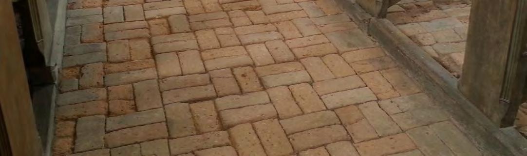
Most early brick floors were bedded directly on the earth or over a layer of sand or clay on a bed of well compacted rubble. Most have acquired a protective and attractive patina over the years. Their surfaces are seldom level but this ‘defect’ will usually contribute to the aesthetic value of a room. Larger flooring units of clay materials, such as ‘pamment’ or flooring ‘pantiles’ are used in similar fashion. There is a strong argument in favour of retaining a brick floor with minimal disturbance.
Many old bricks are of non-uniform dimensions and of irregular thickness. It can be difficult to lift and reverse them and set them to the level on a renewed base. If the joints between bricks have not been filled with mortar it is usually an advantage to leave them so. This will allow any moisture present to evaporate through open joints instead of through bricks. However, where arrises (sharp edges) of bricks appear to be vulnerable to damage by heavy traffic there may be a case for pointing the joints. Where existing pointing needs to be repaired this should be done with weak lime mortar.
When there is no alternative and the floor must be re-laid, the bricks should be set close together on a bed of sand above well compacted hardcore (see also Section 5: natural stone floors).
Heavy silting on the surface can be difficult to remove without saturating the bricks and introducing moisture into the joints. Saturation can lead to efflorescence which can also be difficult to remedy. Surface dirt will usually respond to scrubbing with a bristle brush, using minimal quantities of warm water and a little sulfate free detergent.
Mechanical abrasive cleaning methods can scar the surface and destroy the surface ‘skin’ coating making the bricks more vulnerable to the absorption of dirt and erosion. Many old brick floors have worn to a smooth hard surface and do not require further treatment. Some may benefit from a little beeswax and turpentine polish which will help protect the surface. But a build up of wax will inhibit the breathing qualities of the brick and make the floor slippery. (See also Section 3).
Very small quantities of unpasteurised soured milk, applied with a rag and rubbed in to the brick, is an old method of providing some surface protection to bricks. The milk also imparts a slight sheen. This should first be used on a small trial area. (See also Section 5).
Bannerimage:StMary’sCawston,Norfolk.Credit:SPAB.
17
Plaster floors

Plaster was a sound, warm, economical and fireproof means of flooring and as a lightweight material it was particularly suitable for finishing, mainly, upper floors. Many such floors continued in use and were still being maintained in some areas of Edwardian Britain. They are found particularly in the following counties: Staffordshire, Leicestershire, Worcestershire, Warwickshire, Northamptonshire, Herefordshire, Shropshire, Cheshire and Welsh Borders, Nottinghamshire, Derbyshire, Lincolnshire and parts of Yorkshire.
Gypsum plaster floors comprise a flooring layer that contains gypsum (calcium sulfate) as the binder mixed with aggregates such as crushed brick, burnt wood and coal particles. This layer is typically 35-75mm thick and placed on water reed or straw over timber joists.
with modern concrete, especially after the surface has been wiped with a damp sponge. The presence of reed or straw bedding, a suspected pre-20th century date and signs of later repairs can all provide further clues to the existence of a gypsum plaster floor.
Various forms of deterioration can occur:
• Deflection and/or cracking (for instance, due to movement of joists, perhaps historically)
• Abrasion (especially in areas such as passageways)
• Later work (such as drilling or chasing for building services)
A greater variety of aggregates is usually visible in gypsum plaster floors compared

Holes and cracks can be filled with matching new mortar. Cracks should be carefully raked out first to a depth sufficient to provide a good key and the edges dampened to control suction. Eroded patches or larger sections of defective plaster (or damaging later cement) should be cut back, normally to their full depth, as far as the middle of the nearest supporting joist beneath sound material. Fresh plaster can then be laid on new bedding material secured by laths fixed to the joists. The bedding material can be dressed beforehand with lime putty if this was identified in the old floor.
Images:Banner-gypsumplasterfloor.Credit:SuePickles.Left-laying aplasterfloor.Credit:SPAB.
18
As moisture evaporates to the internal environment salts, which have been transported in the water can be deposited as a solid on or near the surface. In many historic floors this is not excessive and the salts can simply be brushed off. However, if there have been constructional defects, such as blocked gutters or broken drains, there can be a deposition of excessive quantities of salts until the moisture movement is reduced to normal levels after repair of the building’s problems. Rooms where animals were housed, with urine soaking into the floor, or rooms where salted foodstuffs were stored may also have excessive salt contamination. In particularly severe salt-contamination cases poulticing may be necessary.
C HALK FLOORS
Many cottages in medieval England were floored with chalk in areas where the material could be easily obtained. There are also several references to these floors in buildings on moated sites. The addition of sour milk (unpasteurised) was an essential element in strengthening a floor subjected to heavy wear.


The chalk floor of the Medieval Great Hall of the Clergy House at Alfriston, owned by the National Trust, was renewed in 1998. Fine dusty chalk from a local quarry was laid and compacted to produce a smooth surface.
Large chalk aggregate at the surface was thought to be the reason for the failure of the previous floor. Thirty gallons of unpasteurised sour milk was poured over the chalk floor and left to soak in. An initial mould growth occurred, but this has subsequently died back. It took several months for the floor to solidify and harden but it has since withstood heavy visitor footfall.
E ARTH F LOORS
Ear th floors, well consolidated and protected with a layer of rushes or straw, continued in use on the ground floors of humble cottages until the 18th century. Clay mixed with fresh ox blood and ashes formed a surface that was hard enough to be polished. Where still in existence, these floors can be repaired by raking the surface and incorporating high calcium lime and flyash or hydraulic lime depending on the clay content of the earth floor. Many of the comments made in previous sections about not inhibiting breathing potential apply particularly to earth floors.
Writing in the 16th century Erasmus commented on the rush matting in English houses at the time: “The floors are commonly of clay, strewed over with rushes, under which lies unmolested an ancient collection of bears grease, fragments, bones, spittle, excrements of dogs and cats, and everything that is nasty.”
Images:Left-AlfristonClergyHouse,Sussex.Credit:SPAB.Above-tampingan earthfloor.Credit:BeckyLittle.
ExCESSIVE SALT EFFLORESCENCE
19
The SPAB’s top tips for old floors
1. Before undertaking any work to an old original floor, take time to really understand what you are dealing with in terms of age and condition, methods and materials.

2. Do not unnecessarily disturb a historic florr, for example, to put in a damp proof membrane simply because none exists already. Where not causing a genuine safety issue, the patina of time – wear and tear, undulation, fading – should be viewed as something to cherish and maintain. Try to retain features which contribute to the interest and continuity of a historic floor. This may include repairs and patches from earlier times.
3. When putting in new services care should be taken to minimise the intervention on historic flooring. Old existing ducts and the grouping of all services should be sought; this requires planning at an early stage to minimise the impact of any work. Surface mounting may be preferable to the disruption caused by lifting or cutting into historic floors.
4. Always carry out tests for any proposed cleaning or polish products to ensure that the results will be technically and aesthetically appropriate and not damaging to the floor. Follow any neutralising instructions, if given by the manufacturer,
carefully. Before universally applying any product, leave the test area for a period to ensure no adverse long-term reactions occur. If maintenance cleaning / polishing is carried out by someone else it is important that they are given appropriate instructions on materials and methods.
5. I f in doubt seek advice. The SPAB runs a technical helpline for anyone who has a query about the care and repair of a building. The free and completely independent helpline answers hundreds of questions every year from householders and building professionals. SPAB’s helpline is staffed by specialists and is open from Monday to Friday between 9.30 am and 12.30 pm on 020 7456 0916.
Bannerimage:StDavid’sCathedral.Credit:KateGriffin.
20
Gypsum Plaster Floors

SPAB Regional Technical Advice Note
Anthony J Goode DipBldgCons (RICS), IHBC
Spital
020 7377
E1
info@spab.org.uk www.spab.org.uk
The Society for the Protection of Ancient Buildings 37
Square London
6DY
1644
Contents
This Technical Advice Note aims to help prevent continuing unnecessary damage to gypsum plaster floors in old buildings and, consequently, the United Kingdom’s built heritage. Such floors have a long and rich history in areas with gypsum deposits. These are found most notably in the English Midlands but also counties elsewhere, including Yorkshire, Sussex, Somerset and Cumbria.
Once associated with high‑status construction, gypsum plaster floors eventually became ubiquitous in many categories of building. Their popularity declined in the 19th century. Today, they are commonly unrecognised and widely mistaken for later concrete construction. Even where accurately identified, gypsum plaster floors are often wrongly perceived as inherently inferior to modern flooring. There is also little appreciation of their historic value or advice for those wishing to keep old gypsum plaster floors in use.
This advice explains how repair and retention is frequently practical.
Cover image: The historic gypsum plaster floor in the Great Chamber at the Bede House, Lyddington, Rutland.
Photo: Douglas D Kent
SPAB Gypsum Plaster Floors2
1 Introduction ...................... 2 History of use ...................... 3 Construction ...................... 4 Defects and deterioration 5 Work in general ..................... 6 Preparation 7 New plaster ..................... 8 Repairs 9 Care and maintenance ..................... 10 References 11 Other advice ..................... 3 5 6 9 12 13 14 18 18 19 20
1 Introduction
A gypsum plaster floor comprises a screed typically 40 75 mm thick containing gypsum (a soft sulfate mineral) as the primary binder mixed with various other ingredients. This mix is laid over a suspended timber structure or, less often, solid base. In addition to gypsum and related minerals, the plaster contains materials such as charcoal and unburnt coal, limestone, burnt lime, sand and, in crushed form, tile or brick. Some ingredients were incorporated deliberately in the past, including those intended to give bulk, but others may have become part of the plaster incidentally due to crude production methods and the varying degrees to which the gypsum was burnt.
Historically in the UK, gypsum plaster floors possessed attributes that led to their use in preference to timber floorboards while, near to the natural raw materials, were still economical. They provided a hard, durable surface that was draught free and warm under foot, gave good sound insulation, offered fire resistance and were less vulnerable to rot and vermin damage than floorboards.
Another very interesting, practical function was as master masons’ drawing or tracing floors. Here full scale drawings and designs for window tracery, arches and vaults could be inscribed into the soft surface of the plaster for modelling stonework. Examples remain in York Minster and Wells Cathedral.
The composition of a gypsum plaster floor was determined by what materials were to hand locally (see figure 1(a)).
Depending on the constituents, the overall colour of gypsum plaster floors varies from creamy to a nondescript or dark grey, due
in part from the ash of wood or coal, to a pink reddish hue, influenced by brick dust or fragments (see figure 1(b)). Many of the contents are visible with the naked eye or a x10 hand lens, especially after the surface is wiped with a damp sponge. These might include, for example, opaque blue/grey or near translucent particles of anhydrite, a mineral frequently found with naturally occurring gypsum. It is the varied composition of the mix that provides an important characteristic of gypsum plaster floors and helps distinguish them from concrete or cement screeds.
The presence when viewed below of organic bedding material (for instance, reed or straw) can provide a further clue to the existence of a gypsum plaster floor, as does a suspected pre 20th century date (see figure 2). In addition, unlike with concrete or cement, the surface of a gypsum plaster floor is scratched easily with a sharp knife and ‘rings’ when gently tapped. Be mindful, however, that gypsum plaster floors may well contain some later cement repairs.
Although the binder is sometimes partly lime based (indicated by the presence of calcium carbonate), floors of gypsum plaster differ from those bound principally with lime as generally found, for example, in south west England. Aggregates in the latter display a more limited range of colours and fewer pink or red particles. This distinction between gypsum and lime plaster floors is important when formulating repair proposals. Cost effective up to date laboratory analysis is available to aid the accurate identification of the principal binder.

Confusion has frequently arisen over the identification of gypsum plaster floors and those based on lime, which has not been aided by past terminology.1 For instance, according to the literature ‘alabaster floors’, ‘plaster concrete’, ‘lime plaster floors’ or ‘lime ash floors’
 Figure 1: Samples of old gypsum plaster floors:
(a) Typical colour and texture. (b) The varied composition found.
Photos: A J Goode Ltd (a) and Douglas D Kent (b)
Figure 1: Samples of old gypsum plaster floors:
(a) Typical colour and texture. (b) The varied composition found.
Photos: A J Goode Ltd (a) and Douglas D Kent (b)
SPAB Gypsum Plaster Floors3
1(a) 1(b)
all sometimes seem to have been terms for gypsum plaster floors. Even today, the term ‘lime ash floors’ is much used, misleadingly, as a generic name for both lime and gypsum plaster floors.

Surviving gypsum plaster floors are usually of historic significance and worthy of conservation. In many cases, they are original to a building, or date from an early phase in its construction, and this authenticity contributes notably to the property’s special interest. An important characteristic of many old plaster floors is their patina, highly polished appearance and gentle undulation caused by centuries of wear and settlement, which enhances the unique atmosphere of old buildings (see figure 3). Gypsum plaster floors also reflect vernacular building traditions and help create a sense of local distinctiveness. Additionally, the varied range of constituents in such floors can provide aesthetic appeal. Most gypsum plaster floors are simple and were covered with matting in living spaces but for more refined interiors could sometimes be laid to imitate stone.
Regrettably, these floors seem to be treated with less respect than other surviving historic fabric in old buildings and are commonly replaced with alternative materials. Replacement also sometimes occurs because of misguided concerns over the strength or insulating properties of gypsum plaster floors in comparison with modern construction.
This Technical Advice Note considers next the history and construction of gypsum plaster floors (sections 2 and 3). A sound understanding of these aspects will help enable a proper appreciation of the significance of such floors. Good information on the history and construction of gypsum plaster floors also provides information essential for the analysis of any defects (section 4) and effective repair, the methods and materials for which are described later (sections 5 to 8) along with care and maintenance (section 9). Technical terms used in this guidance are defined in our online glossary.2
 SPAB Gypsum Plaster Floors
Figure 2: The presence of organic bedding material, such as reed, can indicate the existence of a gypsum plaster floor.
Photo: A J Goode Ltd
Figure 3: The patination from years of wear in a gypsum plaster floor at The Triangular Lodge in Rushton, Northamptonshire.
Photo: Douglas D Kent
SPAB Gypsum Plaster Floors
Figure 2: The presence of organic bedding material, such as reed, can indicate the existence of a gypsum plaster floor.
Photo: A J Goode Ltd
Figure 3: The patination from years of wear in a gypsum plaster floor at The Triangular Lodge in Rushton, Northamptonshire.
Photo: Douglas D Kent
4
2 History of use
Knowledge of how to produce gypsum plaster stretches back to the ancient world in prehistoric times.3 This insight was exploited in the Middle East during the early Neolithic period around 8 000 BC, when gypsum plaster was used originally for floors with the development of permanent dwellings. It provided these early roundhouses with flooring that was durable and easy to keep hygienic. It typically featured quadrantal mouldings at the abutments with the ancillary walls to form skirtings that aided cleaning.
Floors have traditionally been constructed of gypsum plaster in parts of Europe, such as the Andalucia region of Spain (see figure 4). In the UK, its use for the construction of floors appears to stretch back to the 13th century, following a visit by Henry III to France. Gypsum plaster floors were laid initially in important areas of royal palaces. One of the earliest documentary references relates to the supply of plaster of Paris for the floor of the Jewel Tower, London in 1365 6.⁴ They started appearing in the 16th century in larger houses, such as Harwick Hall, Derbyshire.
By the 17th and 18th centuries, gypsum plaster floors were popular at a humbler level, for example, in farmhouses, cottages and outbuildings/agricultural buildings. According to Nicholson, gypsum was:
‘much used in Derbyshire, for laying the floors of cheese rooms, granaries, &c. After preparing it in the usual way, they mix it with water, and spread it on the floors about 2½ inches [65 mm] thick, which, when dry, forms a smooth surface and durable flooring, the whole expence [sic] not exceeding 1s 6d per square yard.’⁵
Floors of gypsum plaster also found favour in the service areas of country houses, such the attics accommodating servants’ quarters.
Gypsum plaster was used predominantly on first and second floors, presumably because it is slightly soluble in water so more susceptible to erosion at lower levels. More examples are emerging at ground floor level, however, where they are found on solid bases rather than suspended timber structures. The geographical distribution of gypsum plaster floors may also be wider than previously thought as small deposits of gypsum occur in many parts of England. Laboratory testing will help establish exactly where old gypsum plaster floors exist and the SPAB is always interested to hear of further examples that become known.

The use of gypsum plaster floors slowly declined during the 19th century because of changing fashion, the introduction of woodworking machinery and reduction in the price of floorboards, along with the abolition of duty on timber. Timber floorboards became a popular and economical alternative.
Sophisticated techniques employing durable gypsum based pigmented plaster to achieve decorative marble like effects were imported to England from Italy in the 18th century. Such plaster, known as scagliola, is used for floors, as well as columns and wall panels, but is beyond the scope of this Technical Advice Note.
It should be noted that various salt solutions can be added to gypsum to produce patent plasters. For example, Keene’s Cement is made by burning gypsum that has been soaked in a solution of alum. This was sometimes specified for floors in the 19th century.
 Figure 4: Cane bedding forming the underside of a historic gypsum plaster floor in Sierro, Andalucia, Spain.
Photo: Douglas D Kent
Figure 5: Trial gypsum burning on an SPAB course.
Photo: Douglas D Kent
Figure 4: Cane bedding forming the underside of a historic gypsum plaster floor in Sierro, Andalucia, Spain.
Photo: Douglas D Kent
Figure 5: Trial gypsum burning on an SPAB course.
Photo: Douglas D Kent
SPAB Gypsum Plaster Floors5
3 Construction
3.1 Gypsum
Gypsum is a common mineral also known as calcium sulfate dihydrate, which has the chemical formula CaSO4∙2H2O. It has different crystal varieties, including satin spar and alabaster. Although naturally occurring, gypsum may also be produced synthetically as an industrial by product. The water combined within gypsum (‘water of crystallisation’) can be driven off by various degrees of heating (‘calcining’) to create different plasters (see figures 5 and 6).
When gypsum is heated in air between about 150 and 160 °C it is partially dehydrated and yields the hemihydrates of calcium sulfate (CaSO4∙½H2O). These are better known as plaster of Paris – so named because it was first imported from the quarries at Montmartre near Paris. Heating gypsum to higher temperatures drives off more water of crystallisation. At 180°C, the nearly water free anhydrite (CaSO4∙nH2O) is produced and above 250°C the completely water free anhydrite (CaSO4).
Hemihydrate gypsum will revert to the more commonly occurring dihydrate again upon the addition of water, with the resulting paste hardening or ‘setting’ rapidly in ways useful for casting and construction. Chemically, the end result is the same as the original gypsum, hence the term the ‘gypsum cycle’. Modern bagged gypsum plasters contain retarders to slow down the speed of set and also include fillers and other additives. By contrast, fully water free anhydrite does not readily react with water, to create hardened anhydrous plaster, unless an accelerator is added.
The scientific analysis of old gypsum plaster floors indicates that most contain a binder consisting of a combination of hardened hemihydrate and anhydrous plaster. The mineral anhydrite occurs naturally with other forms of gypsum while also being produced by burning gypsum at higher temperatures. It is quite likely that crude early calcining methods inadvertently (if not deliberately) created the anhydrite. Its inclusion would have had the advantage of extending the working time for laying a floor and providing it with a harder finish.
Where ash occurs in gypsum plaster floors, it tends to be present in small quantities and was probably a result of the calcination process, rather than deliberate addition as a separate aggregate.⁶ If lime is present, this is sometimes
in a sufficient quantity to suggest its deliberate incorporation as a binder. In other cases, though, any lime identified is far less significant and indicates accidental inclusion, perhaps, for instance, from bedding mortar that adhered to old bricks crushed up and used in the aggregate.
Early methods of producing gypsum plaster were seemingly more haphazard than today. In the UK, records indicate how production in the past was carried out by burning lumps of gypsum rock close to the source of supply in the open, using fires with wood or coal that could be alight for several days (see figure 6). John Farey in his General View of the Agriculture and Minerals of Derbyshire noted this process in 1813:
‘The process of burning and preparing plaster for floors … is the most wasteful one that can be imagined: an immense pile of brush and billet wood was made, and upon it the old plaster and some new … was laid, and fired: after which, a number of men with flails, thrashed, and rather wasted and spread it about than pulverised it.'⁷
After this burnt gypsum had been broken down and ground into powder, water was added to produce a coarse plaster for flooring.
More economical means of production evolved as demand increased. Easily obtainable gypsum stone of a poorer quality was quarried that was unlikely to have been considered for high quality plaster. Kilns and pan calciners were used for burning the gypsum instead of open fires and mechanical means of crushing components rather than flails.⁸
Referring to old plaster being broken down and reused as aggregate when floors were relaid, The Builder noted in 1854 that:
'it is considered desirable that a certain proportion of old plaster should be mixed with the new; when that is the case the floors are found to set harder.'⁹
3.2 Bedding, floor structure and base
The surface of a gypsum plaster floor consists of a rigid slab formed after the mix was trowelled on wet, usually as a single layer. The bed onto which the plaster was normally placed varied regionally and could be of water reed, hay or straw held down by riven or sawn timber laths nailed across the top of timber floor joists (see figure 7). Such bedding probably adds little to the ultimate strength of the floor but supported the mixture while still wet, like shuttering.
SPAB Gypsum Plaster Floors6
H20 Water added
Slow set
Anhydrite (calcium sulfate) CaSO4
H20 Water driven off Burned >1800C
Gypsum (calcium sulfate dihydrate) CaSO4 2H2O
Burned 150 1600C (calcined)
H20 Water driven off
Plaster of Paris (calcium sulfate hemihydrate)
Ca SO4.½H20
Riven or sawn timber laths nailed to joists
Figure 6: The gypsum cycle: heating of raw material and recrystallisation of hemihydrate and anhydrite back to gypsum. Illustration: SPAB
Gypsum plaster
Water reed, straw or hay bedding
Ground floor lath and plaster ceiling
Joist
Figure 7: Cutaway of a typical gypsum plaster floor. Illustration: Ross Perkin
 SPAB Gypsum Plaster Floors
7
A variation has been noticed in high status buildings where riven hardwood laths were nailed to the joists before the bedding material was laid (particularly where hay was used). (See figure 8). In rare cases, the plaster was spread over boarding.

The joists supporting gypsum plaster for upper floors were generally laid in the same way as for conventional floorboards. The relative lightness of gypsum plaster once set enabled slimmer joists to be employed, though, which saved timber and would have allowed appreciable cost savings in comparison with timber boarded floors. The joists and supporting beams in more modest buildings were very often of unseasoned timber, generally oak.
The underside of the bedding material for a gypsum plaster floor was left exposed or plastered between the joists. Alternatively, in better quality work, a separate lime plaster ceiling might be applied to the underside of the joists. Occasionally, the space between the joists of attic floors was filled with a lightweight sound insulating material, such as chaff or even nutshells.


With ground floors, the gypsum plaster is cast directly over compacted earth, hardcore or stones. A well drained base of this nature helps protect the floors from rising dampness and aids their durability (see figure 9).
Occasionally, a decorative effect was sought. One unusual late 18th or early 19th century example of a solid gypsum plaster floor in Leicestershire appears to imitate more expensive stone. It comprises black and white ‘tiles’ of gypsum plaster laid on a bed of compacted earth and coal chippings. The plaster was cast in situ, which enabled tighter joints to be achieved than with precast tiles. The white ‘tiles’ were formed as one layer but the black ones as two (a lower part of white plaster plus an upper layer blackened with fine coal dust) (see figure 10).
3.3 Finishes
Millar records that bullock’s blood was used to harden floors after they were dry.10 The Builder in 1854, however, commented that ‘it is also usual to give a[n] increased hardness by a coat of linseed oil, and in Nottinghamshire the floors are painted and look extremely well’.11 Rush matting was commonly used historically as a covering for gypsum plaster floors in living areas.
Figure 8: Organic bedding material: (a) Reed, as seen in a sample box cutaway. (b) Laths.
Photos: Douglas D Kent (a) and AJ Goode Ltd (b)
Figure 9: A stone base for a new gypsum plaster ground floor. Photo: Douglas D Kent 8(b) 8(a)
SPAB Gypsum Plaster Floors8
4 Defects and deterioration
4.1 Diagnosis
Knowledge about the history and construction of gypsum plaster floors will assist with the diagnosis of any defects. Once the nature and cause of defects are established, an appropriate form of repair can be implemented to maintain the integrity of the floor yet retain as much of the original fabric as practicable. Many old plaster floors continue to be serviceable but over time can become heavily eroded, weaken or fail (see figure 11).

It is important to carry out a thorough inspection to identify any defects within the gypsum plaster, bedding material or base. Much can often be gained from a visual inspection. There may, however, be an additional need for limited investigations, including the sensitive opening up of concealed areas.

Where a floor is damp due to an overlying impervious floor covering, such as foam backed carpet or vinyl sheeting, this should be removed to aid drying. Moisture contained within the floor cannot evaporate otherwise and condenses instead on the underside of the covering. The condition of the floor can only be assessed properly after it has reached equilibrium with its surroundings. The floor may dry out satisfactorily without the need for more extensive and expensive measures. It should not, therefore, be instantly condemned and replaced.
Bear in mind that intermediate floors provide restraint for enclosing walls in many old buildings so are fundamental to their structural integrity. Where doubt exists about the stability of a floor or supporting components, reference should be made to a suitably experienced structural engineer. The SPAB may be able to suggest the names of engineers who might be contacted.
 Figure 10: A historic solid gypsum plaster floor at Scraptoft, Leicestershire laid to imitate tiles: (a) General view. (b) Alternating black and white 'tiles'. (c) The two layers forming a black tile.
Photos: A J Goode Ltd
10(a) 10(b) 10(c)
Figure 10: A historic solid gypsum plaster floor at Scraptoft, Leicestershire laid to imitate tiles: (a) General view. (b) Alternating black and white 'tiles'. (c) The two layers forming a black tile.
Photos: A J Goode Ltd
10(a) 10(b) 10(c)
SPAB Gypsum Plaster Floors9
4.2 Abrasion and impact damage
Minor abrasion is to be expected but gypsum plaster floors may deteriorate more seriously due to:
• Localised wear. This arises from excessive foot traffic in doorways, passageways or even rooms. The surface will also become polished and, where grit is trodden in, pitted, which exposes and loosens aggregate, and leaves the floor vulnerable to further erosion. Sharp heeled shoes are particularly damaging.
• Scratching and gouging. Plaster floors are susceptible to impact damage from the careless movement of heavy furniture.
• Harsh brushing. Stiff bristle brushing can exacerbate deterioration, particularly of floors suffering from dampness.
4.3 Distortion and cracking
Many old plaster floors are uneven and distorted but this does not necessarily indicate ongoing or recent movement causing damage that requires attention. Gypsum plaster floors can distort and crack for various reasons, leaving them more susceptible to abrasion, impact damage and, in extreme cases, collapse (see figure 12):
• Overloading. Gypsum plaster floors are not designed to take heavy loads. Joists may be weakened or fractured where they support heavy objects or increased loads, for instance, following the sub division of large rooms with new walls or where a building changes use. Misguided attempts are also sometimes made to level up floors by overlaying them with concrete or cement screeds. The weight of this can cause distortion, especially where a floor structure has already been weakened. Further attempts to level a sagging floor with inappropriate materials will frequently exacerbate the deformation.
• Differential movement. Cracking may occur at the interface between gypsum plaster and incompatible cementitious repairs. This leaves the floor vulnerable to abrasion and impact damage.

• Movement or decay of supporting timbers. Many original suspended plaster floors probably settled unevenly early in their history. This is because the timber supporting structures in more modest buildings were often built of unseasoned timber that twisted as it dried out. More serious, ongoing movement may result, however, from the decay of joists or beams, where dampness promotes beetle
 SPAB Gypsum Plaster Floors
Figure 11: An old gypsum plaster floor may look beyond repair but can frequently be brought back into a sound, functioning condition. Photo: Douglas D Kent
Figure 12: The nature and causes of defects should be clearly established before carrying out work involving an old gypsum plaster floor.
Photo: Bonsers Restoration Ltd
SPAB Gypsum Plaster Floors
Figure 11: An old gypsum plaster floor may look beyond repair but can frequently be brought back into a sound, functioning condition. Photo: Douglas D Kent
Figure 12: The nature and causes of defects should be clearly established before carrying out work involving an old gypsum plaster floor.
Photo: Bonsers Restoration Ltd
10
infestation or fungal attack. Deformation and cracking can also arise from settlement, subsidence or the outward movement, or removal, of supporting walls.
• Loss of bedding material. Localised subsidence may occur due to insect attack, associated with dampness, or rodent damage. It will be most obvious if there is no plaster ceiling below.
• Movement of solid base. Ground floors may suffer localised subsidence where their base settles, perhaps due to poor compaction during laying or changes in moisture levels (for example, due to alterations in drainage patterns) or the presence of tree roots. Floors can also be undermined by burrowing rodents.

4.4 Breakdown of plaster
Gypsum plaster can deteriorate for several reasons:
• Dampness. The floors of older, traditionally constructed buildings, which normally perform best without damp proof membranes (DPMs) to stop moisture rising, can suffer from groundwater problems. This may occur, for instance, where a water table has risen or drainage problems develop. Because gypsum is slightly soluble in water, it will break down when subjected to excess moisture, particularly over long periods. Deterioration is exacerbated where soluble salts are present. These crystallise within the pore structure as moisture evaporates, causing the surface to crumble.
Problems are compounded where impermeable floor coverings, such as vinyl sheeting and foam backed carpet, or surface sealants trap moisture. Leaking water pipes and roofs, or water penetration through exterior walls, can cause severe localised decay in gypsum plaster floors. It is strongly advisable to seek advice required with diagnosing a major dampness problem separately from quotations for work to address it. Taking such advice first (for example, from a chartered building surveyor or other appropriately qualified individual) will prevent vested commercial interests giving rise to recommendations for more work than is strictly necessary (which can occur when a remedial treatment contractor is asked to both diagnose and resolve dampness).12
• Strong detergents and other cleaning products. Gypsum plaster can be adversely affected by cleaning agents that introduce
soluble salts into floors.
• Inappropriate repair mixes. Gypsum plaster floors are sometimes overlain or partially replaced by concrete, or a cement screed, in a misguided response to cracking or surface irregularity. Delamination of the later, harder plaster often occurs with movement in the underlying structure.
4.5 Damage from installation of building services
Floors can be compromised by the installation of buried services, such as plumbing and electrical cabling:
• Chasing of plaster. The plaster itself is frequently damaged by cutting out to insert pipe or cable runs.
• Notching or drilling of timbers. The slender joists of many plaster floors may be seriously weakened by notches or holes formed to accommodate services.
• Disturbance of bedding. Reed, straw or hay and the laths used to hold it down may be absent where cut out, and require reinstating before plaster repairs are undertaken.
Figure 13: The special interest of an old building is best protected with conservative repair.
Photo: Douglas D Kent
SPAB Gypsum Plaster Floors11
5 Work in general
5.1 Conservation approach
The demands of conservation impose additional considerations when working on an old building. In particular, a number of overriding principles should be borne in mind when dealing with gypsum plaster floors, in addition to the specific practices described later (sections 6 to 9).
The SPAB exists foremost to promote ‘conservative repair’. For the Society, the value of an old building lies in its antiquity through the mental associations, this evokes. It believes that the special interest of old buildings is best protected by maximising the retention of their historic fabric while minimising any disturbance affecting their overall integrity (see figure 13).
The SPAB’s view is that conservative repair is achieved by adhering to the following key principles:
• Carry out work essential to the long term wellbeing of an old building.
• Employ compatible methods and materials.
• Obtain sound information about the history, construction and condition of an old building, as well as user needs, before making any serious interventions.
Listed building consent may be required from the local planning authority for replacement of a gypsum plaster floor or other work that exceeds like for like repair – if in doubt, consult the conservation officer. It is a criminal offence to carry out work that needs listed building consent without obtaining it beforehand.
5.2 Good information
It is strongly advisable to obtain advice from a suitable specialist familiar with working on gypsum plaster floors when work is required (see section 11.1). Well meaning but misguided jobbing builders who lack the necessary mindset, skills and experience often undertake harmful work on old buildings. In particular, be wary of anyone who suggests the removal of a gypsum plaster floor that is merely worn or suffering from an unresolved structural problem. It is vital to identify and remedy the underlying causes of any problems before embarking on plaster repairs (see section 4).
While many constituents of a plaster floor mix can usually be readily identified visually, the presence of others will often only be
ascertained by laboratory analysis (see figure 14 and section 11.1). Such analysis is normally essential, therefore, to formulate a suitable plaster mix for repairs. It is important when sampling historic plaster floors to ensure the specimen being analysed is representative of the inhomogeneous material. Take care not to inadvertently select inappropriate later work. A range of simple and sophisticated analytical techniques is available to establish the ingredients and their proportions. Be sure, however, to employ an experienced analyst who can interpret the resulting data accurately.
It is good practice to record the condition and appearance of the floor before commencing repair. Photographs are satisfactory in many cases but sketches may sometimes be helpful in addition. A good record of the work should also be made (including the results of analysis).
5.3 Essential work
An abstemious approach should be adopted that prioritises repair in situ over wholesale removal and replacement, which is justified only where absolutely necessary. Gentle wear and undulations in old floors are signs of age and can confer beauty. They deserve respect and are not blemishes to be eradicated. Good preventative maintenance will not only restrain, or even obviate, the need for repairs in the first place, it will prevent the loss of original fabric and is also cost effective.
Be mindful of not inadvertently taking up a historic floor when removing a more recent concrete screed or slab on top of the plaster.
 Figure 14: Drilling to remove a core sample of a gypsum plaster floor for laboratory analysis. Photo: A J Goode Ltd
SPAB Gypsum Plaster Floors12
Where a new use is planned for an old building, ensure that the proposals consider the capabilities of existing plaster floors at the design stage to help prevent unnecessary damage or loss to them.
5.4 Appropriate methods and materials
Methods and materials should be chosen to ensure that the appearance and performance of repairs correspond, as far as possible, to those of the original floor (see figure 15). A sympathetic match is important not only for aesthetic reasons but also to help ensure good durability. Cement or lime plaster should not, therefore, be used as a substitute for gypsum plaster of a suitable composition.
Sample boxes (containing plaster laid in advance of the main work, to demonstrate that the workmanship and materials match the originals) should be prepared on all jobs wherever possible. Once workmanship and finish standards have been agreed, a suitable sample can be used as an exemplar for the remainder of the project. The production of sample boxes also allows the practical aspects of different mixes to be assessed, such as setting times.
Defects in the supporting timber structure causing deterioration should be addressed before the plaster is repaired. Minor carpentry repairs are preferably carried out in situ, where possible, to minimise disturbance to the floor. Some temporary propping may be prudent to ensure a safe working environment during repairs.
6 Preparation
6.1 Removal of existing plaster, concrete or cement screed
Where the removal of old gypsum plaster is justified, as much material as possible should be salvaged because it can usually be crushed and reused in new plaster (see figure 16).

When removing inappropriate concrete floor slabs or cement screeds, trial excavations should be made at several locations to establish whether the material has been laid over an earlier gypsum plaster floor (or other historic surface). If a historic floor surface is discovered, the concrete or cement should be removed carefully because it may be possible to repair the underlying material.

6.2 Repair or replacement of bedding or base
The bedding or base of a floor may require repair or, if unavoidable, replacement before new plaster is laid (see figure 17). Repairs should normally be like for like in terms of methods and materials, including any used for sound deadening.
Where complete renewal is warranted, however, the opportunity could be taken to upgrade the performance of the floor, if appropriate. For example, the thermal properties of a ground floor, although adequate, can be enhanced further by laying the plaster over insulating loose fill rather than more conventional compacted hardcore or earth.
Figure 15: Materials and methods for repairs should match those of the original gypsum plaster floor as far as possible.
Photo: A J Goode Ltd
Figure 16: Old gypsum plaster that is removed should normally be retained for use as aggregate when laying replacement flooring.
Photo A J Goode Ltd
SPAB Gypsum Plaster Floors13
The loose fill layer is overlain with a permeable membrane to stop the wet plaster seeping down into the fill.
Notwithstanding this, the SPAB has a presumption against the insertion of DPMs in old floors. DPMs prevent solid floors from breathing and, by displacing moisture into the bases of adjacent walls, may cause rising dampness.
New bedding material should be cut and laid on the exposed joists. This is held in position by fixed laths on top of the joists. The bedding material can then dressed with lime putty, if identified in the old floor (see figure 18) Alternatively, it may be appropriate to use fine hay or straw to fill the gaps instead of a lime putty dressing where the bedding is of reeds.13

It is generally unnecessary to reinstate lost bedding material where a section of ceiling is being replaced providing this is localised between joists and it does not provide the backing for a ceiling below . The plaster will usually span the joists safely and the underside can be concealed behind a new section of ceiling on separate lathing.
7 New plaster
7.1 Plaster selection
Standard mixes are not appropriate because of the wide variation in the composition of gypsum plaster floors. When undertaking repairs, the existing plaster should be analysed and trials undertaken (see section 5.2) to ensure that a compatible mix is employed.
If a floor is beyond repair, perhaps due to extensive collapse, a plaster mix can be selected to meet the required aesthetic and performance criteria. The modern requirements of a floor may differ from those of the past.
7.2 Gypsum
Modern plasters are invariably different from those found in historic floors due to today’s production processes. Plasters nowadays are purer and lack the inclusions that characterise old gypsum plaster. Two types of gypsum plaster have so far been used to repair and replicate plaster floors with some success.
First, a high strength hemihydrate plaster1⁴ with a setting time of approximately 35 minutes. This shortens when the new plaster is mixed with old reconstituted plaster floors, requiring a retarder to provide sufficient laying and levelling time. Secondly, a high impact finishing gypsum plaster,1⁵ giving a much longer setting time. Either plaster works well, though given the choice, some consider the latter to be preferable.
If possible, it is best to avoid adding a retarder to extend the laying time before the plaster sets. The need will depend largely on the size of repair being undertaken and number of workers to optimise the working time. Possible retarders are trisodium citrate, decorator’s glue size mixed with hydrated lime or natural keratin glue. Some experimentation is advised, however, because using too much can reduce setting capacity.
7.3 Aggregates
Where possible, any gypsum plaster removed from a floor should be crushed and reused as aggregate in new plaster, as was frequently done historically. This helps ensure the visible aggregate matches the old floor, particularly as the surface wears and the old particles become exposed. It is also likely to encourage crystalisation. New plaster is added to the aggregate in proportions identified by analysis. If recycled material is not available, many of
Figure 17: New reed bedding being laid.
Photo: A J Goode Ltd
SPAB Gypsum Plaster Floors14
the materials found in old plaster floors can be substituted by adding a selection of new aggregates to the plaster. Gypsum rock and anhydrite are not readily available but can be sourced. Other ingredients, such as brick or tile, sand, coal, charcoal, stone, limestone or burnt lime are available. Most, though, will have to be crushed to an appropriate size, or purchased ready prepared, and then blended if a good match and colour is to be achieved.


7.4 Mixing
Laboratory analysis of original material is important because it not only establishes the binder but also the type and proportions of aggregates needed if as near as possible a repair is to be achieved, and is probably more economical than a trial and error exercise (see section 5.2). Whether using original crushed flooring material or processed aggregates identified visually, guessing the quantities for new mixes is inadvisable and time consuming.
The main issue affecting the mixing of plaster for a floor is the volume of water required (before it is added to the blended aggregates). The water content for the plaster is found in the product information sheets but more may be needed for dry aggregates. This can be
SPAB Gypsum Plaster Floors
Figure 18: Bedding material being dressed with lime putty (a) over which, as in this demonstration, gypsum plaster is laid. (b) .
Photos: Douglas D Kent (a) and AJ Goode Ltd(b)
Figure 19: Mixing gypsum plaster in a plasterer’s bath. Photo: Douglas D Kent
15
18(a) 18(b)
estimated by adding a measured volume of water to a known amount of dry aggregate. For example, if 1 kg of dry aggregate absorbs, say, 300 ml of water without excess, multiplying the water content to the weight of aggregates used in a mix will give the extra water needed.
Mixing for relatively small areas can take place in a plasterer’s bath using rakes or shovels, or a heavy duty electric drill and whisk designed for the purpose, and for larger scale works a cement mixer (see figure 19). In both instances, the dry blended material is scattered into the container holding the measured volume of water. The resulting mix should be fluid and easily spreadable.
7.5 Laying
To experienced plasterers familiar with modern floor screeds, laying gypsum for a plaster floor is not dissimilar except the mix will be more fluid and, depending on the type of plaster used, can set more quickly. Buckets or wheelbarrows may be used to transport the mix but care needs to taken when walking or wheeling up to, and placing the mix onto, a fragile bedding material. The floor is laid between timber battens that are removed to allow the laying of the sections

in between. The plaster is levelled to a uniform thickness with a long wooden float and the surface finished with a steel or wooden float as works proceeds (see figure 20).
When reed or straw bedding was used in the past, a regular practice was to spread onto this an initial, quite thin, layer of lime putty to prevent the main mix, which can be fairly fluid, running through any crevices or small holes. An alternative to lime putty dressing, as mentioned above, was to use fine hay or straw to fill gaps between reeds. Where the underside is to be plastered between the joists, though, plaster can be left to run down between the bedding material and then floated off from below to form the pricking up coat for the ceiling.

For larger areas, a reasonable amount of time will be needed for repairs, once laid, to cure and harden before they can cope with foot traffic and longer for loading, possibly from two to four weeks.
20(a) 20(b)
SPAB Gypsum Plaster Floors
Figure 20: New gypsum plaster being laid between temporary timber battens (a) before the adjacent sections are infilled (b)
Photos: Jamie Miles
16


 Figure 21: Cracking in gypsum plaster: (a) Raked out for repair. (b) Filled with a matching new mix. Photos: Douglas D Kent (a) and A J Goode Ltd (b)
Figure 22: Patch repair: (a) New plaster being spread over a dressing of lime putty. (b) Finished level with the existing surface. Photos: A J Goode Ltd 21(b) 21(b) 22(a) 22(b)
Figure 21: Cracking in gypsum plaster: (a) Raked out for repair. (b) Filled with a matching new mix. Photos: Douglas D Kent (a) and A J Goode Ltd (b)
Figure 22: Patch repair: (a) New plaster being spread over a dressing of lime putty. (b) Finished level with the existing surface. Photos: A J Goode Ltd 21(b) 21(b) 22(a) 22(b)
SPAB Gypsum Plaster Floors17
8 Repairs
8.1 Scope
Minor cracking and surface spalling due to wear and tear is generally not a serious problem providing the floor structure below is sound. Cracks and spalling can be made good but are probably best left alone. Where deterioration is more extensive, repair will need to be considered and is not as difficult as frequently assumed. It can range from filling a crack to the partial replacement of a floor.
8.2 Repairing cracks and holes
Holes from redundant pipe or cable runs can be filled, as can wide cracks if stable.
Cracks and fractures should be raked out carefully to a depth sufficient to provide a good key for the repair mix, their edges undercut and loose debris removed. Damaged areas, large or small, should be cut back as far as the middle of the nearest supporting joist beneath sound flooring.
Gypsum floors are quite soft and cutting can be done with old wood saws, hacksaw blades or, in highly experienced hands, mechanical tools, particularly those with oscillating blades. Electric drills and masonry bits may be used to form a series of close holes, weakening and controlling removal without using a ‘heavy hand’. Care must be taken to ensure that vibration does not damage adjacent ceiling plaster.
It is important that the raw, undercut edges of the floor being repaired are dampened with water to control suction from the new plaster mix before it is inserted. The new plaster should be finished flush with the existing surface (see figure 21).
To make good isolated sections, cracks and fractures, refine the crushed material to an aggregate size appropriate for the width of the gaps. The repair is made easier by the slight expansion of gypsum as it sets, which will close the joint crisply between the existing and new flooring.
8.3 Making good minor areas of surface spalling and deteriorated plaster
Surface depressions can be made good, where necessary, using new gypsum plaster spread over the defective area after first undercutting the edges of the existing, adjacent plaster. In more serious cases, where filling is not practical, an area of disintegrating plaster will need removing and re laying (see figure 22). Care should be taken to minimise damage to attached bedding material. It can be difficult, however, to achieve a good match because most floors are highly polished after years of use and this effect is extremely hard to replicate in a repair.
No attempt should be made to seal powdering surfaces because this may well exacerbate damage (see section 4.4).
9 Care and maintenance
9.1 Good practice
Good care and maintenance of gypsum plaster floors helps ensure their long term survival. Sensible housekeeping includes regular monitoring of any surface deterioration or cracking.
9.2 Cleaning and surface treatments
Plaster floors should be regularly swept or dry vacuumed on a low suction setting to remove dirt and dust. Rugs, mats or loose carpets are best lifted first. Gently loosen any embedded dirt by dry bristle brushing but avoid aggressive wire brushing or similar, as this will cause damage.
Cleaning the floor judiciously with warm water and a sponge, after sweeping or vacuuming it to remove any abrasive material, can reveal the colour and texture of the surface. Place doormats at entrances to catch dirt and reduce abrasion to floors by grit taken into the building.
In most cases, proprietary surface treatments are inadvisable. Such products can greatly accelerate deterioration (see section 4.4).
SPAB Gypsum Plaster Floors18
9.3 Floor coverings and protection from impact damage
Natural, breathable coverings can help protect a gypsum plaster floor. Rush matting is a noted traditional covering but requires dampening down weekly to prevent embrittlement. More convenient alternatives today are sisal, coir or hessian backed woollen carpets, rugs or mats.
Foam backed carpets or other impervious coverings should be avoided because these will seriously compromise air circulation below and may cause dampness to form, leading to degradation of the floor.
Where woolen carpets are laid, a suitable material comprises an 80% wool/20% nylon mix laid over a natural colour, natural fibre contract quality hair/jute underlay. It is best to use runners or loose laid carpet. Sticking on underlay or other materials is not recommended. It not only makes future removal very difficult but also the glue might have an undesirable effect on the floor.
Plaster floors are quite strong but relatively soft, so vulnerable to sharp, pointed objects that will cut into the surface. High heeled shoes, therefore, should not be worn on unprotected floors. Floors can also weaken from point loading or impact from heavy house or office furniture. Problems may be avoided by the selection appropriate furnishings, careful positioning of furniture around the edges not in the centres of rooms and possible use of boards to spread weight. Additional protection can be afforded by using castor cups beneath furniture.
10 References
1 Wright ( 2005, p143) comments on how authors in the ancient past appear to confuse gypsum and lime generally
2 See https://www.spab.org.uk/advice/glossary
3 Wright, op cit, pp156 159
4 Taylor (1996, p6) states that Henry de Yevele, deviser of the King’s works of masonry, ‘received individual payments for supplying plaster of Paris for rendering the floor of the Jewel Tower’ in London
5 Nicholson, 1841, p337. John Speed, writing about Nottinghamshire in the 17th century, commented that ‘betwixt the Joysts they lay only long Bulrushes, and thereon spread this Plaister, which being thoroughly dry becomes most solid and hard, so that it seemeth rather
to be firm stone than mortar, and is trod upon without all danger’ Derbyshire Miscellany, 2009, p123.
6 Notwithstanding this, Stafford Holmes has commented to teh SPAB that it is not unheard of for ash to be used as a lightweight aggregrate and comprise up to 50% of the gypsum plaster mix. He has suggested that the sources of the ash in such cases could be many, including lime ash (the partially burnt residue from kilns).
7 Farey, 1813, p16. See also Pilkington (1789, pp147 148)
8 Nicholson, 1841, p181 describes how the material for gypsum plaster was brought to London in crude state, then calcined and ground in a mill
9 The Builder, 25th March 1854, p149. Farey, op cit, p16 also notes ‘the plaster of old floors being burnt, and mixed with fresh Gypsum, with good effect’
10 Millar, 1897 p498
11 The Builder, op cit, p149
12 For more on treating dampness problems, see SPAB Technical Advice Note on Control of Dampness.
13 Stafford Holmes has reported to the SPAB that he has seen the use of fine hay or straw as an alternative to a lime putty dressing on old gypsum plaster flooring at Hardwick Hall in Derbyshire. the use of straw in this way is referred to by Millar (op cit, p498). Stafford Holmes suggests that lime putty may have been used historically in addtion to hay in some instances.
14 Saint Gobain Formula ‘Crystacal R’ or equivalent
15 Tarmac Tilcon or equivalent
SPAB Gypsum Plaster Floors19
11 Other advice
11.1 Contacts
Where work to gypsum plaster floors is being considered, the SPAB may be able to suggest suitable specialists, including contractors and structural engineers. If plaster analysis is required, the SPAB may also be able to provide the names of firms with testing facilities.
11.2 Further reading
Barley, M W (1961) The English Farmhouse and Cottage, London: Routledge & Kegan Paul
(The) Builder (1854) 'The use if Gypsum or Plaster for Chamber Flooring', The Builder , 25th March, p149. Reprinted in Derbyshire Miscellany 18(5) Spring, p123
Clifton Taylor, A (1987) The Pattern of English Building, 4th edition, London: Faber & Faber
Colston, B and Watt, D (2002) ‘Analysis of Historic Lime and Gypsum Plaster Floors: Part 1’ in Journal of Architectural Conservation, 8(1), pp57 73
Colston, B, Watt, D and Goode, A (2002) ‘Analysis of Historic Lime and Gypsum Floors: Part 2’ in Journal of Architectural Conservation, 8(2), pp47 68
Farey, J (1813) General View of the Agriculture and Minerals of Derbyshire; With Observations on the Means of its Improvement: Vol 2, Board of Agriculture and Internal Improvement, London: B McMillan
Firman, R J (1964) ‘Gypsum in Nottinghamshire’ in Bulletin of the Peak District Mines Society, 2(4), pp189 203
Goode, A, Royall, C and Bagnall, B (2002) ‘An Analysis of Plaster Floors in the East Midlands’ in Lime News, 9, pp40 48
Kent, D D (2018) Control of Dampness, SPAB Technical Advice Note, London: Society for the Protection of Ancient Buildings
Millar, W (1897) Plastering: Plain and Decorative: A Practical Treatise on the Art and Craft of Plastering and Modelling, Reprint 1998, London: B T Batsford. Shaftesbury: Donhead
Nicholson, P (1841) Practical Masonry, Bricklaying and Plastering, both Plain and Ornamental, London: Thomas Kelly
Pilkington, J (1789) A Viewof the Present State of Derbyshire: With an Account of its Most Remarkable Antiquities: Volume 1, Derby: J Drewry
Salzman, L F (1967) Building in England Down to 1540: A Documentary History, 2nd edition, Oxford: Oxford University Press
Sarjeant, W A S (1962) ‘Gypsum in Derbyshire’ in Bulletin of the Peak District Mines Historical Society, 1(6), pp45 53
Slocombe, M (2017) The SPAB Approach to the Conservation and Repair of Old Buildings, London: Society for the Protection of Ancient Buildings
Speed, J (1676) An Epitome of Mr John Speed’s Theatre of the Empire of Great Britain and his Prospect of the Most Famous Parts of the World, London. ’
Taylor, A J (1996) The Jewel Tower, London: English Heritage
Ware, I (1767) A Complete Body of Architecture. Adorned With Plans and Elevations, from Original Designs, 2nd edition, London: Printed for J Rivington, L Davis, C Reymers et al
Wright, G R H (2005) Ancient Building Technology: Volume 2 – Materials: Part 1 Text, Technology and Change in History – Volume 7/1, Leiden and Boston: Brill
SPAB Gypsum Plaster Floors20
The content of this publication is offered in good faith, but neither the author nor the Society can accept responsibility arising from incorrect or incomplete information that may be included. The use of traditional materials may incur risks that are different from those associated with modern materials. Manufacturers’ and suppliers’ guidelines should always be observed. This document is intended as a contribution to a continuing debate and we welcome comments.
Written by Anthony J Goode. Additional input from Douglas D Kent. Mortars section contributed by Stafford Holmes. This Technical Advice Note draws on, and supersedes, material contained in SPAB Information Sheet 12 (1996) by Phillip Hartley. The author of this Technical Advice Note is indebted to the following for their help: Julie Butcher (Sales Area Manager, Saint Gobain Formula), Paul Robinson (PAR Nottinghamshire, supplier of specialist casting plasters), Analytical Services at the Department of Geology, University of Leicester, Chris Royall (co author of ‘An Analysis of Plaster Floors in the East Midlands’), Tim Ratcliffe (Tim Ratcliffe Associates, architect and historic building and traditional materials consultants), Philip Heath (heritage consultant), Stephen Bull (conservation contractor) and Nigel Copsey (conservation contractor). Grateful thanks to Judith Rodden for editorial advice and Sally Stradling with proofreading. Produced by Catherine Peacock. The sources of illustrations are given adjacent to them together with any copyright where not belonging to the SPAB.
This publication is dedicated to the memory of Anthony J Goode (1945 2018), who died during its production. Anthony’s contribution to the cause of the SPAB was immense and he will be remembered for his kindness, enthusiasm and willingness to share with others.
The Society for the Protection of Ancient Buildings (SPAB) believes old buildings have a future. From cottages to castles and from churches to cathedrals we are here to help buildings and the people who care for them. Through our unique training schemes, courses, advice and research we help people put our expertise into practice.
Today the SPAB encourages excellence in new repair and good design to enrich and complement the built historic environment. We train new generations of architectural professionals and building craftspeople to conserve this landscape with sensitivity and skill, and we play a statutory role as adviser to local planning authorities. In our casework we campaign actively to protect old buildings at risk.
SPAB: hands on history. Join today to support our positive, practical approach to building conservation.
Published by the SPAB in October 2019
© SPAB 2019 Edn 1 Rev 1
SPAB ref T5502M www.spab.org.uk
ISBN 978 1 898856 36 8
The Society for the Protection of Ancient Buildings 37 Spital Square, London E1 6DY Tel 020 7377 1644 info@spab.org.uk www.spab.org.uk
A charitable company limited by guarantee registered in England and Wales Company No 5743962 Charity No 111 3753 VAT No 577 4276 02
Slate and Stone
Roofing in Wales and the Marches

SPAB Technical Advice Note
Terry Hughes BSc (Hons), FIoR Dp Man
Richard Jordan FIoR SPAB William Morris Craft Fellow
The Society for the Protection of Ancient Buildings
37 Spital Square London E1 6DY 020 7377 1644 info@spab.org.uk www.spab.org.uk

Contents
This Advice Note describes the production and use of slates and stone slates in Wales, west Gloucestershire, and the counties of Herefordshire, Worcestershire and Shropshire, and deals with the maintenance and repair of roofs and wall cladding. It explains the basics of the region’s slating practices, including many of the local variations, and considers details specific to the traditions of roofing and cladding in the region. Additionally, it discusses adaptations, where appropriate, to incorporate modern requirements such as improved thermal performance. It includes brief explanations of novel but now rare slating systems, which were developed or promoted by the slate industry in response to mill fires and war time materials shortages as well as to expand the market for slate. Videos illustrating some of the slating techniques are linked from the text.
1 Introduction 3
2 Recording and assessment 11
3 Work in general 13
4 Repairs and re-slating 18
5 Slating systems and techniques 32
6 Specifications and detailing 44
7 Maintenance 64
8 References 66
9 Video links 66
10 Other advice 67
Cover image: Field shelter, Cwm Nantcol, Snowdonia National Park
Photo Terry Hughes
2 SPAB Slating in Wales and the Marches
1 Introduction
1.1 Development of the slate and stone slate industries
Today the term Welsh slate implies a roof of single sized, fairly thin and fairly smoothtextured slates originating from the huge quarries and mines of north-west Wales. This disregards the wide variety of products which were produced in hundreds of quarries working stone, shale and slate prior to the 20th, century and the diversity of roofs created using them. It also overlooks the special slate types, such as Colloidal slates and Patent slating, which were promoted by the major quarries to expand their markets.
There is archaeological evidence throughout the region of roofing slates found in excavations of Romano-British sites such as the fort at Segontium, Caernarfon and the bathhouse at Tremadoc, Gwynedd (see figure 1) and stone slates on villas at Ely near Cardiff and Llantwit Major in South Glamorgan. However, the earliest post-Roman records of slate quarrying date from the 13th century, when Edward I used slate to roof parts of his castles at Caernarfon, Conway and Carmarthen.

By the 15th century there is evidence that slate was being quarried in the Nantlle,
Ogwen, Llanberis and Conway valleys of Caernarfonshire (see figure 2); in the Berwyn range near Llangollen; at Aberllefenni in south
Figure 1: Hexagonal slates excavated from the remains of a Roman bathhouse near Tremadoc Gwynedd still in perfect condition after being buried for 2000 years. Produced from the Nantlle to Bethesda slate belt, they are examples of diagonal slating (see section 5.9).

Merionethshire and in mid and south Wales, especially in Pembrokeshire. By 1583 slate had become the principal export from Wales to Ireland.
Vernacular slates and stones are the product of small quarries. They are all random-sized and generally rough-textured. They include the shales and slates produced in south-west, midand north Wales, and the stone slates of south Wales and the border region (see figure 3). So the region’s roofscape falls largely into three categories: the vernacular or preindustrial slates and stones; modern slates developed
SPAB Slating in Wales and the Marches
Photo: © Gwynedd Archaeological Trust,
Figure 2: Barnacle-encrusted slates from the Pwll Fanog wreck in the Menai Strait near Bangor Gwynedd. The slates, approximately 10 x 4 inch, originate from the Cambrian age, Nantlle to Bethesda slate belt. The wreck was carbon dated to the latter half of the 15th century.
Photo: Terry Hughes
3
Terminology
Technical terms used in this Advice Note and not explained here or in the text are included in an online glossary (see section 10.5). The meanings of some words are variable and need to be understood before reading on (see video 0).
Slate - Strictly, this term should be applied only to stones derived from sediments which have undergone low-grade metamorphism - the process of compression and heating under which the sedimentary minerals are recrystalised and re-orientated perpendicular to the compression. They can be split into thin, strong and flexible sheets, which are not parallel to the original sedimentary layers. In practice, where the specific type of rock is not relevant or is obvious, the term slate can be used to mean other roofing stones such as shales or sedimentary sandstones and limestones.
Shales - These are splittable rocks which have not undergone metamorphism, or less so than true slates.
Stone slates - A commonly used, but geologically deprecated, term for splittable sedimentary rocks. In geology texts, the term tilestone is often used instead.
Tilestone - When capitalised Tilestone is used for a specific stone slate exploited along the Tilestone Formation on the north side of the South-Wales coalfield and north-eastwards towards Ludlow in Shropshire.
Cleavage - The property of true slates which allows them to be split. Also, a verb, to cleave. In quarries, the synonyms rive or riving are more common.
Fissile, fissility -The property of sedimentary stones which allows them to be split along bedding planes.
Random slates - Slates with a variety of lengths and widths sold by weight. They are usually described in the form longest to shortest lengths by random width, for example, 24 - 12 x R inches. They are sold by weight with an estimated coverage.
Tally slates - All slates in a consignment of the same length and width. Sold by count.
Slate length - The length of slates sold by quarries is the overall dimension from the tail to the head (bottom edge to top edge). But for top-fixed slates the effective length is the dimension from the tail to the bottom of the fixing hole and this is typically 25 mm (1”) less than the overall length. This is important because it is the length to the fixing hole which is used to establish the gauging of the roof and hence the area that can be covered with a given quantity or weight of slates. Failure to appreciate this can result in expensive under-estimates of the cost of a roof. When carrying out random roof surveys or recording, it is the length to the fixing hole which should be measured.
Proportionation - Any system for setting out the slating - gauging the laths or battens - in which the gauge is determined by dividing the slate lengths by a number.
Slating in thirds - Gauging by dividing the slates’ lengths by three.
Pin slating - In this proportionation system slates are laid triple-lapped and the lath gauge is determined by dividing the slates’ lengths by 3.5. Hence three-and-a-half pin slating.
4 SPAB Slating in Wales and the Marches
Figure 3: Bedding and cleavage. Sandstones and limestones are sedimentary rocks which are fissile along the bedding layers. Shales have been very slightly changed from sedimentary deposits, either under their own weight or by very low grade metamorphism. Although they have been described in the past as slates they are not slates geologically and many did not last long on a roof. True metamorphic rocks, such as slates, schists and phyllites, have been changed from sediments by pressure and heat in the earth’s crust. They split along the resultant cleavage planes almost always at an angle to the bedding. This is known as slaty cleavage.

during industrialisation; and specialised products and roofing techniques.
In the past there were hundreds of slate quarries in Wales. They too fall into three groups: the small operations supplying their immediate locality; the somewhat larger ones which supplied slates beyond the immediate area but only on a modest scale; and the major quarries and mines of the north-west which had national and international importance. Table 1 is based on Richards (see section 10.5 Richards) and shows the operations which he ranked as more significant within their locality. However they are not all of similar size: some, although important for vernacular buildings locally, were quite small. The major and nationally important examples are shown in bold.
As the major quarries developed they devised new products and novel, for the UK, methods of slating (see section 5). Slates gradually increased in size, eventually producing sizes up to 48” (1.2 m) long, known variously as rags, queens and tons (see figure 4). The latter were so named because they were sold by weight.
By the mid-19th century, the north Wales quarries had grown large enough to be able to segregate slates into single sizes, known
as tally slates to distinguish them from random slates sold by weight. It was cheaper to construct roofs with these and gradually single-sized slating displaced the older styles and those quarries which were too small to compete closed down. Despite attempts by the Arts and Crafts movement to encourage the use of vernacular slates and techniques, their use declined throughout the 19th and 20th centuries. Small and later large quarries closed until, by this century, only the major operations in north-west Wales at Bethesda near Bangor and at Blaenau Ffestiniog are still producing roofing slates.
Figure 4. As the major quarries developed and gained access to the deeper, better cleavage slate they were able to make larger slates. These were known as rags, queens or tons. As much as 48” (1.2 m) long they were able to compete with the large sandstones slates of the Pennine counties.
 Slating in Wales and
Illustration: Terry Hughes
Photo Terry Hughes
Slating in Wales and
Illustration: Terry Hughes
Photo Terry Hughes
5 SPAB
the Marches
Alongside the introduction of tally slates, sawn battens became available and these allowed slates to be centre-nailed rather than top-fixed.
Slates nailed in this way do not need to be bedded in mortar because they are inherently resistant to wind uplift. Bedding therefore ceased for all but the smaller slates, which continued to be tophung. Torching persisted as a means of draughtproofing and to prevent snow penetration, until the general adoption of roofing underlay from the mid-20th century. Today, for new buildings, the old styles of slating have been almost entirely supplanted by single-size slates, centre-nailed to sawn battens over underlay. Happily, many of the old roofs still survive to add variety to an
increasingly bland roofscape. But their future is by no means secure. Roofs continue to be lost on the ill-informed assumption that modern slating is better than the traditional systems.
Specialised slate roofs are rare Indeed, some types may have disappeared long ago but they are important to the history of the industry and wherever they still exist they should be carefully conserved.
Modern (tally) slating is ubiquitous. It roofed the houses, factories, commercial buildings and chapels of the 19th and 20th centuries and continues to thrive in the 21st. It was only with the post-war availability of cheaper asbestos-
Formation Region Location Slate quarries and mines
Betws-y-Coed and Llanrwst Rhos, Foel, Cwm Machno, Bwlch Gwyn, Hafod Las
Silurian North
Ruthin, Corwen, Llangollen and the Tanat Valley
Craig Rhiwarth, Llangynog, Cwm Maengwynedd, Penarth, Moelfferna, Moel Fferna, Cambrian, Wynne
Bala to Ffestiniog Braich Ddu, Aran
Cwm Pennant to Porthmadog
Prince of Wales, Cwm Bach, Gorseddau
North
Beddgelert to Porthmadog Coesor, Rhosydd
Blaenau Ffestiniog Wrysgan, Cwmorthin, Oakley, Llechwedd, Bowydd, Diffwys, Maenofferen, Graig Ddu, Manod, Bwlch-ySlaters, Cwt-y-Bugail, Rhiwbach
Ordovician
Rhyd Ddu Glanrafon, Rhos Clogwyn, Bwlch Cwmllan
Coris & Aberlleffeni
Gaewern, Abercwmeiddaw, Braich Goch, Aberlleffenni, Cynerau, Ratgoed
Mid
Twyn & Machynlleth Allt Goch, Fron Goch, Bryn Eglwys, Glandyfi, Morben, Minllyn
Dolgellau to Barmouth Egryn, Henddol, Golwern, Arthog, Cefn Gam, Penrhyngwyn
South Carmarthen
Llwynpiod
Cardigan and Fishguard Rosebush and Bellstone, Fforest, Cilgerran, Gilfach, Glogau
Cambrian North Nantlle to Bethesda
Penrhyn, Dinorwic, Vivian, Glyn Rhonwy, Garreg Fawr, Treflan, Tal-y-Sarn, Pen-yr-Orsedd; Dorothea, Glanrafon, Moel Tryfan, Alexandra
Table 1: Historical sources of slates in Wales, after Richards. There were many other quarries which had a small production or a short duration. Richards lists most of them in The Gazetteer of the Welsh Slate Industry.
6 SPAB Slating in Wales and the Marches
Geological age Historical name Bedrock source unit
Jurassic Early Lias
Triassic
Tarporley Siltstone Formation
Carboniferous Pennant Pennant Sandstone Formation
Brownstones Formation
Stone slate source
Cheshire: Combermere Abbey Gloucestershire: Ashleworth; Tewkesbury
Shropshire: Grinshill
Around Bristol; Iron Acton; Forest of Dean; north of the South Wales Coalfield
Shropshire: New Invention; Forest of Dean
South Wales: Talgarth (Tredoman) quarry; Skokholm Island 1, 2
Devonian Old Red Sandstone
Senni Formation
Freshwater West Formation (St Maughans Formation)
Near Cwmyoy 3
North of Hereford: Dinmore Hill; Kipperknoll; Garnons Hill
Herefordshire: Olchon Valley to Golden Valley; north of Hay-on-Wye Moor Cliffs Sandstone Formation (formerly Shropshire: Five Turnings
Downton Castle Formation in the north (formerly Clun Forest Formation)
Silurian Raglan Mudstone Formation) Bettws-y-Crwyn
Tilestones Formation in the south
Cheney Longville Formation
Shropshire: Downton Castle; Ludlow
Wales: Llandybie; Onnen Fawr; Golden Grove; Long Quarry; Cilmaenllwydd; Pont ar Llechi; Mynedd Meddfai; Mynedd Eppynt; Brecon
Shropshire: Cheney Longville; north and west of Wistanstow
Alternata Limestone Formation Shropshire: Soudley quarry
Chatwell Sandstone and Chatwell Flags Shropshire: Chatwell
Hoar Edge Grit Formation
Shropshire: Ruckley near Acton Burnell to Harnage
Table 2: Historical sources of stone slates in South Wales and the Welsh Marches. Silurian and Devonian stratigraphy based on Barclay et al. (2015). Sources shown in italics have been recorded or are probable but are unconfirmed.
Howe J A (1910) The Geology of Building Stones, London: Edward Arnold. Lawman J (1948) Skokholm. an Island Remembered. Tiverton: Halsgrove. Davies J and Horak J (2009) Building Stone Use in Brecon Beacons National Park. Cardiff: National Museum Wales.
Ordovician
7 SPAB Slating in Wales and the Marches
cement imitations and concrete tiles that their predominance faltered. Guidance on this type of slating is not included in this guide. It is available from manufacturers and in BS5534 Code of Practice for Slating and Tiling. It should be noted though that the scope of BS5534 explains that:
‘This British Standard gives recommendations primarily intended for the design, performance and installation of new build pitched roofs, including vertical cladding, and for normal re-roofing work, including repairs, using slates, tiles, shingles and shakes and their associated components. This British Standard does not cover the structural design of the roof.
The recommendations contained in this British Standard might not be appropriate for the re-slating or re-tiling of some old roofs, particularly where traditional and/or reclaimed materials are used. Users intending to adopt any of these recommendations for old roofs, and especially for historically or architecturally important buildings, are advised to consult with the local planning authority or an appropriate conservation organization to check their suitability. ‘
Stone slate sources are shown in table 2. They nearly all worked sandstones across south Wales and in the border counties, serving local markets. The production of stone slates, which had a similarly long history to slates in the region had ceased entirely during the 20th century but in recent years, due to work by Historic England (formerly English Heritage), continuous production has been re-established in some quarries or could be restarted elsewhere for specific projects, such as was done for Harnage (Hoar Edge) slates in Shropshire (see 10.5 Wood).
The techniques of stone slating are largely unchanged. Mortar is used for head-bedding and torching but not for tail-bedding. The main changes are the adoption of battens rather than laths, nails rather than pegs for fixing, and underlays.
Slate and stone slate producers are given in section 10.2.
1.2 Significance and conservation
Vernacular roofs are important elements in the character of historic buildings and settlements in the region, and give individual buildings, towns and villages their sense of place. This is in part due to the materials themselves, with their different colours, textures and sizes, but also to the way in which they are laid and detailed.
Because of the long availability of modern slates, vernacular slate and stone roofs now remain mainly on early religious buildings and manor houses, as well as farms and low status buildings in the more remote regions and especially in the uplands.
Where stone roofs have been conserved the techniques are usually applied correctly. Unfortunately, many are changed to different stones or even to slates or fake stone slates.
Welsh slate and stone roofs are predominantly double-lapped, but there are single-lapped examples and triple-lapping has been identified on some roofs (see figure 5(a - d)). A common form of double-lapping is slating in thirds where the slates’ lengths are divided by three to set out the lathing (see figure 5(e) and video 1)
For many years, there have been misunderstandings of the traditional slating systems and confusion about their details, resulting in inappropriate repairs. In particular, where the roof includes curves, such as swept valleys, attempts to use large and wide modern slates are doomed to fail.
The techniques for producing weather-tight roofs were often local, expressing the individual way in which slaters made the slating work. They were based on skill, understanding of how water moves on a roof and experience. Sadly, many of today’s slaters do not have these attributes and often a detail which has worked perfectly well is condemned out of ignorance or changed for lack of confidence to be able to do the work successfully (see figures 6 and 7).
Although most of these slate roofs have been lost to modern tally slating, many remain and recent researches have revealed a much greater variety of slating styles and techniques than had been recognised in the past. Many of these were constructed in response to the characteristics of the locally made slates; especially their sizes and
SPAB Slating in Wales and the Marches
8 SPAB Slating in Wales and the Marches
5(a). In double lap slating the third course overlaps the first, fourth overlaps the second and so on, usually by a specified amount - the head lap. This is how all new and many old roofs are constructed. (Ditherington Flax Mill, Shropshire).
5(b) and (c). In single lap slating each course of slates overlaps only the one immediately below and the vertical sides are butted against each other. Consequently, the perpendicular joints are open and have to be weathered in some other way.

In Patent slating at St Georges Church, Everton, Merseyside, above, the perpendicular joints are sealed with slate cover strips bedded in a putty.
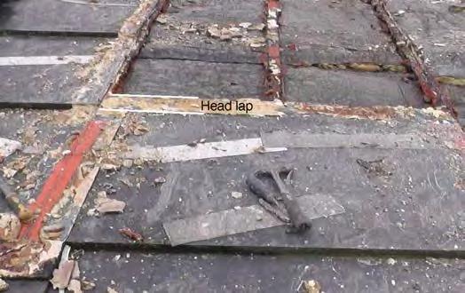

Close to quarries, very large slates, which would not survive haulage over a long distance, are often used single lapped on farm buildings or sheds. The perpendicular joints on this pig sty near Caernarfon are weathered with mortar fillets.
5(d). In triple lap slating the fourth course overlaps the first and so on. This makes it possible to use slates which would be too narrow for double lap slating without risking leaks. It also improves the wind resistance. Less common in Wales than in south-west England, it has been identified only on a few roofs so far.
Figure 5. Welsh slate and stone roofs are predominantly double-lapped (a) but there are single-lapped examples (b) and (c) and triple-lapping has been identified on some roofs (d). A common form of double-lapping is slating in thirds where the slates’ lengths are divided by three to set out the lathing (e).
All photos Terry Hughes
5(e). A system of slating in thirds where the head lap and the lath gauge are equal to the slate length (from tail to peg hole) divided by three. The method uses a divider rather than mathematical division, similar to the techniques of mediaeval masons (video 1).


9 SPAB Slating in Wales and the Marches
the range of lengths in which they were made. Some were sold in just two or three lengths which was critical to how, for example, valleys were laid (see section 6.7). The key problems for the conservation of these roofs are that:

• They are not inspected properly before stripping.
• The vernacular techniques are not understood.
• Most slaters are not experienced or trained in the techniques.
• New slates and stones in vernacular sizes are assumed to be unavailable (see section 10.2) and tally slates or other stone slates are specified instead of the originals.

As roofs were renewed the vernacular
systems were changed to the modern system even when laying random slates. Modern slating recommendations and detailing as exemplified by British Standards together with modern slates, have been applied to historic roofs without regard to their visual and technical needs. This is inappropriate for conservation, not least because the standards omit vernacular techniques. The issue of the differences between modern and historic slating should be dealt with at the design stage of a project.

Whilst the slates and stone slates themselves are durable and may last hundreds of years, the roofs have a finite life determined by the fixings used to support them. Pegs and laths rot and nails rust. Roofs are known that may be between 150 and 200 years old, but there will be very few in situ any older than this. Older buildings may well have had their roofs renewed two, three or more times during their existence, and whilst the original slates may be salvaged and reused once or twice, the act of stripping and relaying a roof destroys most of the evidence of the earlier roofing techniques.
It is very important that the details of roofs are recorded before the slating is stripped, and that the information obtained is used to derive appropriate specifications for re-slating (see
SPAB Slating in Wales and the Marches
Figure 8. Recording the way a roof was slated can be difficult, perhaps involving several measurements on each of 50 or more courses. Equipment should be chosen to be convenient when working on a roof ladder. Photography and voice recordings will ensure details are not lost or recorded for the wrong course. Also, every slate removed destroys it’s relationship with the surrounding slates, so if a video recording can be made it allows the stripping to be ‘reversed’ to check the details subsequently.
Photo Terry Hughes
Figures 6 and 7. The Welsh slate valley in the top photo which had been satisfactory for at least 100 years was changed to a lead lined type for no good reason.
Photos Terry Hughes
10
figure 8). Each surviving example is likely to contain valuable information about traditional craft techniques and local variations.
In general, the existing form and details of each historic building should be respected and retained during any campaign of repair. This extends not only to the overall appearance of the building but also to the construction methods employed.
The broad principle of retaining existing details does not mean that they should simply be replicated without thought. There are situations where details may need to be sensitively adapted to improve performance but, if so, this should follow careful analysis in such a way that the traditional local style and appearance is maintained, and be within appropriate statutory consents.
2 Recording and assessment
2.1 Recording and condition surveys
Any work on historic roofs should always be based on an understanding of the existing roof and how well it has performed. Each surviving example is likely to contain valuable information about historic craft techniques. Many of these techniques and details cannot be seen externally, but unless their presence is known and understood, the roof cannot be repaired or renewed authentically. So it is essential that the recording of such information is undertaken before or as the slating is stripped and the results used to develop a specification for the re-slating. This will minimise the possibility of delays and errors in the ordering of any new slates, and, importantly, will give the owner of the building more certainty over the final cost. If no survey is done, assumptions about the quantities of slates needed will have to be made at the time of specifying the work in order to obtain prices.
Where defects occur, they are frequently down to poor maintenance, unsuitable alterations or inadequately sized members, and result in
decay or distortion of the roof. It is important to distinguish these factors from inherently poor design or construction.
2.2 Structural deterioration, rafter settlement and deflection

Most historic roofs will have moved during their life. Commonly, because of inadequate restraint by couples etc, the eaves may have spread, pushing out the walls, and the ridge may have settled. Rafters may also have settled along their length or adjacent to walls. These features give roofs much of their character and should not be rectified unless there is a clear structural reason to do so.
Some roofs were constructed with a concave curve in the rafters, either deliberately or simply because they had a natural curve. This should not be misinterpreted as settlement. It helps the slates to sit tightly together. Also, rafters may have been raised at abutments to turn water away from the vulnerable junction. For the same reason valley boards may be offset from the centre line (see figure 9).
Every effort should be made to conserve the structure that supports the roof covering. It is frequently one of the least altered parts of an old building and may provide valuable clues about its history. These range from smoke-blackened timbers where a medieval open hall preceded a chimney, to remnants of early decoration and evidence of smoke bays or louvres. Many old roof structures also constitute fine examples of craftsmanship, jointing is often exemplary and features such as crown posts, moulded beams and traceried
Figure 9. The structure of a roof is part of how the slating works. Rafters and valley boards were placed to tilt the slates and direct water away from vulnerable junctions such as abutments and valleys.
Photo Terry Hughes
Slating in Wales and the
11 SPAB
Marches
Slate durability
There have been problems with imported slates in recent years. These are caused by inclusionscarbonates (calcite etc) or metallic minerals, collectively known as pyrite or pyrites. They can be present in the slate as distinct crystals or veins, or be dispersed within the slate’s structure. When exposed on a roof, expansive reactions take place, converting pyrite to iron oxide and carbonate to bicarbonate or sulfate. These can result in staining, cracking, flaking or blistering of the roofing slate. Some forms of pyrite can be stable so its susceptibility cannot be decided visually. Other failures have been the result of mudstones and siltstones being sold as slates. These disintegrate very quickly on roofs.
Slates should conform to BS EN 12326-1 Product Specification and should be tested by the quarry once a year or for every 25 000 tonnes of finished slates they produce. It is particularly important that they conform to the scope of the standard which defines a slate geologically. Quarries must provide attestations of conformity to the standard (Known as Verification of Constancy of Performance in the Construction Products Directive).
Specifiers should be aware that it is not safe to simply specify ‘slates conforming to BS EN 12326-1’. This is because the durability tests in the standard have more than one level of conformity and such a specification allows slate with any of the conformity levels to be supplied. The range of conformity levels was necessary to accommodate all the slates produced throughout Europe, some of which are less durable than is acceptable in the UK market. A specification should state the conformity level for three of the tests: water absorption – less than 0.6% or more than 0.6%; thermal cycling - T1, T2 or T3; and sulfur dioxide exposure - S1, S2 or S3. (The S1 and T1 categories and the lower the water absorption - ideally lower than 0.3% - are the most durable.) There are other tests which need to be considered as well. Further explanation is available (see the link below).
Rust-staining indicates the presence of oxidising metallic minerals and a general whitening of the slates will usually be the result of a high carbonate content, although this can also be caused by carbonates leaching out of mortar or by lead-staining. A specialist report will be needed to determine whether the slates already on a roof should be replaced. It is important to understand that while oxidation of pyrite can be a serious problem (which in recent times has been mainly associated with imported slates) not all pyrite oxidises and some will do so without causing problems.
Slate breakage can be due to wind forces, roof settlement or imposed loads, such as people walking on the roof or, more importantly, because the slates are inherently weak. Wind damage is usually localised on the lee side of hips, ridges or other changes in the roof shape. Broken slates can be replaced individually but if the cause is wind damage a review of the fixing method or slating technique or the slate’s strength is advisable. Failure due to inherent weakness is usually a symptom of imported slates which are too thin. A roofing slate’s strength is a function of its thickness and the inherent strength of the rock, known as its modulus of rupture (MoR). Hence an inherently weak rock will be satisfactory only if it is made thicker than one with a higher MoR. BS EN 12326-1 specifies the minimum thickness for slates in relation to their MoR and size. The minimum thickness for specific slates should be declared by the manufacturer.
The slate standard itself does not contain a classification of slate durabilities but an explanation of the tests is available at www.stoneroof.org.uk/tests2.html and two organisations - the NHBC and the NFRC - have established their own requirements or guides - see section 10.5. The roofing slate standard is revised from time to time. The BSI and the NFRC can advise on the latest version.
12 SPAB Slating in Wales and the Marches
early spandrels may be found.
A technical assessment will often indicate that stabilisation of the structure is all that is necessary. However, deflection or settlement of the structure may have created undulations in the roof slope which are impossible to slate without gaps, especially for larger slates or stones. In this case, when reslating it is acceptable (and essential) to ease the undulations by packing the rafters or similar. Where settlement is less severe, gaps under the slates can be reduced by using narrow slates which will fit more tightly across the undulations (see figure 10).
2.3 Nail failure
Rusting of iron nails used to fix laths or slates is the main cause of slates becoming detached from the roof. Loss of slates individually indicates that it is the slate nails which are failing (see figure 11(a)). This will be a gradual process and they can be refixed for a time. If lath nails fail, several slates in a course will slip (see figure 11(b)).
2.4 Lath failure
Lath failure is indicated by courses of dropped slates or undulations in the roof plane. If the failure is extensive then the roof will need to be reslated. Laths may be unable to carry the weight of the slates, if they have been weakened by rot or insect attack, or if the slating has been grouted and slurried. Repeated slurrying increases the load on the laths and when it becomes too heavy for the lath nails large cracks form (see figure 12(a)). In Pembrokeshire, Anglesey and elsewhere, to overcome the slippage barbed wire is laid over the ridge and turned under the eaves slates or nailed
Dimensions
into the rafters and covered with a mortar fillet (see figure 12(b)). This is only a temporary solution. Slurrying reduces the roof’s ability to breathe, resulting in rotting of the laths and structural timber.
2.5 Slate failure
Slates currently sourced from Wales are durable and will reach the end of their lives only after many, commonly hundreds, of years. Typically, the process of slate ageing is a general softening in the overlapping parts of the slates. Less durable slates may fail for three main reasons: the presence of deleterious minerals; inherent weakness; or because of mechanical stress (see box page 12).
3 Work in general
3.1 Conservation approach
The demands of conservation impose additional considerations when working on an old building. In particular, a number of overriding principles should be borne in mind when dealing with vernacular slate roofs, in addition to the specific practices described in sections 4 to 7. These are set out in the ‘SPAB Approach’ (see 10.5 Slocombe).
The SPAB exists foremost to promote the care and protection of old buildings through maintenance and ‘conservative repair’. For the Society, old buildings are best safeguarded and enjoyed by maximising the retention of their historic fabric. Through maintaining historic fabric, it is possible to retain character, history
Although metric dimensions were adopted long ago, many slaters still work in inches and some slate manufacturers still make imperial size slates and quote approximate metric equivalents. In this guide, where past practices are described and where direct quotations are provided from historic documents, the inch dimensions are used. Otherwise, and for descriptions of modern practice, approximate metric equivalents are given with the imperial dimensions in brackets.
It is important to understand that so-called metric equivalents made by some quarries are not exact. A 500 x 300 mm slate is not the same size as a 20 x 12” slate (508 x 305 mm) and this can result in problems if they are mixed on a roof. Additionally, some Welsh quarries made their slates oversize so a nominal 20 x 12” slate was actually 20.25 x 12.25” equal to 514 x 311 mm.
SPAB Slating in Wales and
13
the Marches
10(a)
10(b)

11(a)


11(b)


12(a)
12(b)
Figures 11 If slate nails rust and fail, individual slates will slip (a). If the lath nails fail, whole courses of slates will collapse (b).
Photos Terry Hughes.
Figures 10. Often structural movement will require only stabilisation. Undulations in the roof can make it difficult to lay slates without gaps. Often, for random slating, the use of narrow slates will overcome the problem.
Photos Terry Hughes.
Figures 12. The use of mortar can prolong the life of a failing roof but the weight of repeated slurrys will eventually overwhelm the fixings and large areas will slip (a). In some regions barbed wire from eaves to eaves and nailed to the roof structure is used to resist slippage (b) Photos Terry Hughes.
14 SPAB Slating in Wales and the Marches
and interest. This does not rule out change, but change should be carefully considered, respectful and should add interest or assist long-term care.
The SPAB Approach is achieved by following these key principles:
• Carrying out work essential to the longterm well-being of an old building.
• Employing compatible methods and materials.
• Obtaining sound information about the history, construction and condition of an old building, as well as user needs, before undertaking serious interventions.
3.2 Selecting an architect or surveyor
An architect or building surveyor may be employed on larger, more complex projects, or projects where the re-slating is only part of the work. This should give the client protection if things go wrong, and a competitive tendering procedure should ensure that value for money is obtained. Professional advisors should be selected who have the right knowledge and experience to specify and inspect the work. For sources of names (see section 10.1).
3.3 Selecting a slater or slating company
It is most important to ask skilled and knowledgeable slaters to tender for the work. The key is to ensure parity of tendering. Then the lower price can be chosen. It is usually unwise to make a selection based on cost alone, as an inexperienced slater may simply have underestimated the cost after inadvertently leaving out a step in the slating process. Problems can also arise if the main contractor is allowed to choose the slater because this too may be primarily based on cost.
The National Federation of Roofing Contractors (NFRC) operates an accreditation scheme for heritage roofing companies which includes those working with stone roofs and slates in tally, random and Patent formats.
There are national vocational qualifications (NVQs) for roof slating and tiling, and construction site management (conservation)
(see table 4). Older but highly skilled slaters may not have such qualifications, but this should not disqualify them from consideration.
These qualifications may be required by clients or be included in grant conditions.
A slater should be able to show roofs which they have worked on successfully and provide references. It is wise to view roofs that a company has repaired or reslated, preferably recently. Although an external view cannot reveal all the mistakes which may have been made, examples of good workmanship to look out for include:
• Evenly diminishing margins – no margins taller (longer) than ones lower in the slope. Do not mistake undulations caused by wavy laths with bad setting out.
• Perpendicular joints roughly central on the slate below – any joints lying closely above each other are a serious fault. In tally slating the joints should be central on the slate below and straight up the roof.
• Tidy mortar – neatly finished at the tails of the slates, verges and abutments
• Ridge tiles fitting closely onto the slating without large mortar beds except where the roof undulations make this difficult. In stone roofing it can be difficult to avoid mortar showing, but it should be minimised.
• In the roof space there should be no signs of leaks or dampness but these might be visible only if there is no underlay.
• Similarly, no tail bedding mortar should be visible from the underside of the roof but do not confuse this with head-bedding or torching (see figure 13).
The slater should be asked to provide a statement covering all the steps in reslating the roof including:
• Survey and recording – how the roof will be inspected before and during stripping, to ensure historical details will be conserved and technical detailing will be replicated or if necessary changed. This may be subcontracted to a specialist and may have been carried out prior to tendering.
• Specification review – advising on unsuitable or impractical aspects of the specification.
• Method statement – a description of how
15 SPAB Slating in Wales and the Marches
the work will be organised and executed
• The re-slating process - a description of the process of carrying out the work. This aspect is important because comparison between tenderers will highlight any steps which have been omitted.

• How they will deal with any faults or damage caused, for example, when dismantling scaffolding.
Quotations should state the total area of the slating work to be done so that differences can be checked; and any aspects which are unknown until the roof is stripped should be clearly explained. It is also very important that all quotes are based on the correct gauging system. A price mistakenly based on slating at double-lap when three-and-a-half-pin is specified is going to seriously underestimate labour and materials.
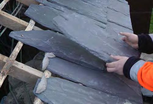
3.4 Specifications
Any work on historic roofs should always be based on an understanding of the existing roof and how well it has performed. Ideally, a survey to record and photograph the constructional details should be carried out prior to writing the specification. This will involve some opening-up of the roof. The survey should cover the slate sizes, their condition and gauging and lapping system, and the details for eaves, valleys, verges, abutments, hips, ridges and dormers. It should also assess whether the roof has performed satisfactorily or if it has deteriorated prematurely because of some inherent defect. Care and experience are needed to differentiate between cause and effect. The survey should be carried out by a
Figures 13. Head bedding (a) and torching (b) will be visible inside a roof. This is normal and not a problem.
Photos Terry Hughes
Table 4: Vocational Qualifications in roofing. NVQ Title S/NVQ level CSCS card Roof Slating and Tiling 2 Blue Roof Slating and Tiling (including random slating) 3 Gold Diploma in Heritage Skills Roof Slating and Tiling 3 Gold + Heritage Skills Construction Site Supervisor Conservation 3 Gold Construction Site Management Conservation 6 Platinum Conservation Consultancy 7 Black 16 SPAB Slating in Wales and the Marches 13(b)13(a)
slating consultant, contractor, conservation accredited architect or building surveyor, provided they are experienced in the local slating styles and detailing.
The specification can be prepared based on the survey findings. Where modifications are required to fulfil other objectives such as environmental performance, they should be based on sound information. In particular, care should be taken where insulation is introduced and where a method for venting any moisture from the batten space may need to be provided.
This Advice Note includes roof details which vary across the region and should be replicated during repairs or re-slating. However, the location and geographical extent of their use is not necessarily known, so their application on a particular roof should be based on research, a survey or other reliable information rather than assumptions.
A written specification will allow the work to be detailed and the standards of materials and workmanship to be set out, so that all slaters who are pricing the work can do so against the same document. The prices can then be judged on an equal basis. If the work includes more than slating, and is to be managed by a main contractor, a good specification will ensure that the method and standard of slating can be understood by all who tender and can be met by the main or slating subcontractor. Under certain contracts a particular slating firm can be nominated. The specification should cover the following issues.
• Survey and recording if required.
• Policy on retention of historic details and materials.
• Slate source, size or size range, thickness and colour.
• Gauging. For pin slating the slate length divisor should be stated: 3.5 for roofing and 2.5 for cladding are typical. For slating in thirds, the gauge divisor is 3.
• Side lap. For random slating the requirement is to set perpendicular joints approximately central over the slate below;.
• Battens or laths and fixings – sizes and materials.
• Slate fixing method – nailed or peg-hung.
• Slate fixings – nails or pegs, sizes and materials.
• Mortar, if required, including any preparation procedures and precautions to ensure satisfactory curing
• Underlay if required
• Insulation and means of ventilation if required
• Details for eaves, verges, hips, valleys, dormers and ridges.
3.5 Listed building consent
For listed buildings, most changes to the construction details will require listed building consent from the local authority. Relevant changes will include:
• Reslating of a roof at the end of its life, where renewal would affect the building’s character.
• Removal and alteration of material and/or detail of archaeological or historic importance.
• Alteration of a detail affecting, for example, ridges, valleys, hips, abutments verges or the style or size of dormer windows.
• Change from one slate or stone type to any other slate, stone or to clay or concrete tiles, imitation slates or sheet products.
• Use of slate or stone of a different geological type, including another source quarry within a particular geological type.
• Change from riven laths to sawn battens or the reverse.
• Introduction of underlay.
• Introduction of counter-battens which raise the roof line.
• Change of slate fixing method, for example, top-hung to centre-nailed.
• Change in the overall range of slate lengths which would significantly affect the roof’s character.
• Use of new slates or stones that have been prepared using non-traditional methods, such as sawn edges which have not been dressed to give a bevelled edge.
• Change of ridge or hip material, such as from one stone type to another or to reconstituted stone, concrete or clay ridges.
• Introduction of building services or ventilation details that would significantly alter the character of the building.
17 SPAB Slating in Wales and the Marches
Local policy on these issues should be checked before making proposals for alterations. The policy is likely to cover three main options.
• Completely authentic reslating – an exact replication of the existing style and techniques.
• External appearance authentic, but modern methods adopted, for example, nailing rather than peg hanging.
• Either of the other two but including modern innovations like insulation.
The third option is most likely to be driven by the building regulations.
3.6 Building regulations and other controls on roofing work
In addition to listed building consent, building regulation or, for many places of worship - a faculty, building regulations approval will be required for any increase or decrease to the weight of the roof covering. This will include a change from a slurried to a normal roof.
‘If you want to carry out repairs on or re-cover less than 25 per cent of the area of a pitch or flat roof, you will not normally need to submit a building regulations application. You will need approval, however, if:
• You carry out structural alterations
• The performance of the new covering will be significantly different to that of the existing covering in the event of a fire
• You are replacing/repairing more than 25 per cent of the roof area, in which case, the roof thermal insulation would normally have to be improved.
• Where more than 25% of the roof area is to be replaced, the person intending to do the work has a legal obligation to contact the local authority building control department in relation to the upgrading of insulation to comply with the Part L of the Building Regulations (see section 7.6).’
Section 3.5 in Part L2B of the Building Regulations states that listed and other historic buildings and places of worship are exempt from the need to conform with the energy requirements (see 10.5 Historic England).
All bats and some birds and plants which live
on or in roofs are protected. This will often limit the time of year when work can be done. There are controls on the type of underlay where bats are present. Currently only bituminous roofing felt known generally as BS747 1F may be used, but it must be hessian reinforced and not contain polypropylene fibres. The county wildlife trusts will be able to advise (see section 10.4).
4 Repairs and reslating
4.1 Alteration of details
It is normally assumed that a like-for-like repair or re-slating – same slates, same slating system and gauging, same bedding if originally used, etc – will perform satisfactorily in the future. However, the implications of the increasing incidence of deluge rain and more severe storm force winds consequent on climate change should be considered in deciding on the gauging and the fixing method. An improved specification can usually be adopted without impact on the appearance of the roof, but specialist advice may be needed so that all the implications of changes are considered and an integrated solution achieved. Simply applying the recommendations for each element in isolation is unlikely to be successful.
4.2 Structural repairs
All roof-work should be carried out from a safe means of access that does not damage the
Maximum gap 470 mm between top and middle rail and middle rail and toe board

Figure 14. Roof work should be carried out from a scaffold designed for safe access and able to carry the weight of the slates.
Illustration NFRC
SPAB Slating in Wales and
18
the Marches
roof. Scaffolds should be designed to carry the weight of stacked slates or stones and to be wide enough to allow sorting and redressing. The NFRC provides guidance publications(see figure 14 and 10.5 National Federation of Roofing Contractors, 2009).
It is better to repair rather than replace roof timbers. Consult a suitably experienced structural engineer where necessary (SPAB may be able to suggest names) and leave only minor repairs to roofers. Whilst conventional carpentry techniques alone will frequently be suitable, strengthening using steel may be justified where it allows more timber to be retained than would otherwise be possible. Resins and consolidants should be used with great care, and other means of reinforcement, such as plastic rods, should be employed only where they can be justified. For more about work to roof structures (see 10.5 Boutwood).
Where active decay exists, the first priority is to eliminate causes of dampness and promote drying. Chemical treatments are frequently unnecessary and should only be used judiciously where justified as a secondary measure, for example, when it is difficult to reduce moisture levels sufficiently. Degraded surface material should not be removed (defrassed) without good reason. Serious mutilation can result.
Keeping roof spaces clear of rubbish and debris discourages decay. Timbers may be vacuumed or brushed down – though take care not to remove any medieval smoke blackening or evidence of early decoration that is of archaeological value.
4.3 Slates
Although slate and stone roofs which are reaching the end of their life can be kept weather-tight for many years by regular maintenance, eventually they will have to be stripped and reslated, typically when 5-10% of the slates have slipped or been lost. The decision to reslate is often precipitated by the repeated cost of scaffolding for repairs.
When carrying out repairs the primary aim should be to retain the maximum amount of historic fabric without compromising the
effectiveness of the roof. The existing slates should be reused if they are still sound or if they are damaged or softened, they may be dressed down to remove any defective areas.
Only slates or stones from the local sources can produce an authentic appearance. Those from other locations should not be used unless there is no local source. For extensive reslating, new slates should be used to make up any shortfall. This may be local authority policy and a condition of any grant-supported works.
Claims of unavailability or long delivery times should always be checked with the quarries. It may be worth delaying the project for a few months until the right slates can be produced, since the life of a well-slated roof is likely to be more than 100 years. Only where it is impossible to obtain suitable new slates should the use of slates reclaimed from other buildings be considered and these should be from a known source to discourage theft. Reclaimed slates will not last as long as new ones and their use inevitably means some other building will have lost its historic roof. Often, they are sourced from several other roof,s so their remaining life will be mixed. They should be checked for softening and damage, especially around the fixing holes. Affected areas can be dressed off but this may result in a shortage of the longer sizes, with a consequent change in the appearance of the roof. It is better for appearance and for reasons of durability to consolidate old slates on to one or more slopes and to use the new ones on others.
When stripping and reslating random roofs any shortfall should be made up with new slates supplied in a mix as they arise in the quarry, with an appropriate mix of widths. Using a few lengths and widths selected from a quarry’s standard sizes will not produce an authentic roof.
Normally, the new and old slates should be fixed on separate slopes. When the existing slates are consolidated and sorted into lengths, the number of courses of each length can be calculated.
Large slates and stones slates are not always
19 SPAB Slating in Wales and the Marches
immediately available, and have to be specially ordered. Suitable block for such large slates may not be readily available so the order should be discussed with the quarry as early as possible.
The quarries are always willing to make special slates, such as for Patent slating (see video 2), but they will need a detailed specification of what is required and almost always time to organise production of any special slates (see figure 15). An order might include sizes, quantities, colour, texture, and most importantly the date work is to commence, as well as the scheduling for each stage of large projects. It is always wise to discuss the order and work programme well in advance. If a roof is to be stripped and re-slated, there will inevitably be uncertainty about the quantities of slates needed until the numbers of reusable slates are known. Experienced slaters or independent consultants can advise on this before stripping commences.
The individuality of random roofs derives from the mix of slate sizes (see figure 16) . Historically, no attempt was made to supply a specific mix of sizes and this policy should be respected for most re-slating work today (see figure 17). How the slates were fixed, their laps and the detailing was mainly a response to the climate and roof pitch.
Generally, metamorphic slates should conform to the highest level of BSEN12326-1 - S1, T 1 and water absorption no greater than 0.3% (see box page 12). Slates specially produced from historic sources might not conform to the standard but if they have a long history of successful use this may be convincing.
There are no formal standards for stone slates. Again, any produced from an historic source may be able to show long and successful use. Otherwise, for slates from a new source the best advice is to store them on edge off the ground outside or on a trial roof which can be quite small - ideally for a year - and then inspect them for cracks and delamination etc.

Colloidal slates


In the 1930s the Oakley Quarries Group developed a process for colouring natural
Figure 17. Orders for new slates should not ask for specific sizes. The correct way is to specify the longest and shortest and allow the quarry to produce a natural mix of sizes. It is the slater’s job to produce an effective roof from the mix supplied. Hereford stone slates made for St Mary’s Church, Portbury, Somerset
slates by coating them with sols - a colloid of solids suspended in liquid - and baking it on. Available in a range of earth colours (see figure 18(a)) the coating was claimed to be ‘absolutely fast even if boiled in concentrated acids or alkalies. A promotional leaflet listed 71 buildings in Wales and England slated with them and many can still
Wales
Figure 15. Quarries can make slates to specific sizes or formats given reasonable warning. These slates measuring 1350 x 950 mm were made by Welsh Slate for the Patent slating of St George’s church, Everton, Merseyside.
Photo Terry Hughes
Figure 16. The appearance of slate and stone roofs depends on the mix of sizes which the quarry can produce. St Mary’s Church, Kempley, Gloucestershire
Photo Terry Hughes
Photo Terry Hughes
20 SPAB Slating in
and the Marches
be seen (see figure18(b)).

4.4 Slate repairs
The thickness and size of missing or damaged slates must be determined and matched and this will probably involve opening up the slating.
If the slates are pegged it may be possible to swing adjacent slates aside and hang the new slate. If the slates are nailed or if the slating has to be opened for another reason, such as renewing a horizontal lead gutter then, if they can not be swung aside, it may be necessary to remove a triangle of slates, so that each one can be accessed for re-fixing and the last one can be fixed with a copper tingle (see figure 19). Inevitably, any bedding or torching will be damaged and this should be renewed.


Re-fixing slates by simply bedding them in mortar should be avoided but is sometimes necessary as an emergency and purely temporary measure. Cement mortar should not be used as any water which gets behind it cannot evaporate through it and more damage will ensue. Lime mortar of the torching type (see Table 5) placed on the slates where water can not reach it is preferable. Slates fixed in this way will not be fully secure.
Roofs near the coast have often been repaired in the past by grouting and slurrying with mortar (see figures 12(a) and 12(b)). This is
most common in Pembrokeshire where there is specific conservation control on such roofs. It is also seen in other coastal counties but has rarely been conserved in the past. However, the issue should be discussed with the local conservation officer or Cadw when repairs are necessary. Grouting or slurrying leads to structural deterioration and will eventually cost far more than if the roof had been re-
Figure 18. Colloidally coloured slates produced by Oakley Quarry in the 1930s (a) are still visible on roofs today. The example in 18(b) is near Llandudno, Conwy.
Photo Terry Hughes
Figure 19. Slipped slates can be refixed with a tingle. Copper is better than lead, which tends to unroll.
Photos Terry Hughes
18(b) 18(a)
21 SPAB Slating in Wales and the Marches
slated instead. Although slurried roofs are a distinctive feature, of Pembrokeshire in particular, they are a last resort for a roof which has failed.
Covering slates with hessian and bitumenTurnerising - or spraying foam on the slates’ undersides is also damaging. These techniques make it expensive or impossible to re-use the slates and reduce the ventilation through the roof, increasing the risk of rot or insect attack (see 7.5 Roof maintenance). This will be aggravated where insulation is installed in the roof.
4.5 Thatch legacy
Many of the vernacular roofs we see today would have been thatched before they were slated - outside the slate producing areas probably not before the late 19th century - and some of their original features persist simply because it was difficult or costly to change them.
The most obvious legacy is the roof pitch. Thatched roofs need a much steeper roof than slates to shed water but it is rare that the pitch would have been reduced for a change to slating.
In Waunfawr and Rhos Tryfan near Caernarfon there are examples of slates laid on turf on loosely laid birch branches on pole rafters (see figures 20(a -c)). It has been speculated that the use of slates in this way from small quarries close at hand, was a continuation of the process of regularly renewing the thatch weather coat but using slate instead. However they could equally well have been laid directly to a turf roof.


The outer leaves of gable walls are often raised with the slates butted up to them (see figures 21(a) and 21(b). This is often only on the wind exposed end of the roof. This is unnecessary for slating so it is thought to have originally been to prevent thatch being blown off. It is an awkward detail for slating (see 6.3).
Thatched roofs sometimes have slates or stones at the eaves (see figure 22). This can be to support the thatch without the need for sprocketed rafters or may reflect extensions to
Figure 20. The roof of the Caer Adda cow shed (a) in Waunfawr near Caernarfon and (b) inside in 2005 before it was moved to St Fagans museum (c). Relaying the the roof (c).
Photos Terry Hughes
22 SPAB Slating in Wales and the Marches 20(a) 20(c) 20(b)
Figure 21 ( The raised outer leaf of a gable wall (a) and (b) was originally to prevent thatch being blown off. It is unnecessary for slating but has persisted.

Gable support for thatch (c). Kennexiton farmhouse Gower. Now at St Fagans museum. https://museum. wales/stfagans/buildings/ kennixton/


Photo Terry Hughes
the building. It has also been suggested that, for very low eaves, it was to prevent livestock pulling the thatch off.
Eyebrow dormers are a natural technique for thatch which fits easily to curves. This is not so for slates so perhaps on older buildings slated eyebrows are a replacement for thatch.

As most of these details are unnecessary or awkward for slating it is difficult to understand why they are so often adopted for buildings that were never thatched. Maybe architectural style has taken precedence over practicality.
4.6 Fixings
Lath nails should be no less durable than galvanised or sheradised and sized to suit the laths or battens. Stainless steel nails are sometimes specified, especially in marine situations, but not all types are equally durable. There have been failures associated with AISI grade 304 slate hooks in coastal areas and current advice is to avoid this grade for roofs and only use 316. However, standards and grades of stainless steel are changing and the NFRC technical bulletin 11 should be consulted for full details.
For fixing 50 x 25 mm softwood battens a 3.35 mm shank diameter nail is recommended in BS 5534. Shank length and diameter should be chosen to provide adequate pull-out resistance for the building’s situation, height etc. BS 5534 provides further guidance. Smaller nails will be needed for fixing thin riven laths to avoid splitting them or the laths can be pre-drilled. Alternatively cleats (cooper’s hooks) can be used (see figure 23).
Pre-drilling may be necessary when nailing into old hardwood rafters or where a fragile ceiling is fixed to the rafters.
Historically, the most common fixings for slates and stones were soft- or hard-wood pegs, but many other materials, including animal bones, were used (see figure 24). Wood pegs were roughly square section, whittled to a slight taper and forced into the hole until almost flush with the surface of the slate. Peg making
Figure 22. Slates below thatch. Roson farm, Pembrokeshire.
Photo Terry Hughes
21(b)
23 SPAB Slating in Wales and the Marches
21(c) 21(a)
would be a wet day task and they would be allowed to dry naturally or be dried in an oven the day before using them (see figure 25). Once inserted in the slate they would absorb moisture and swell to fit tightly in the peg hole.

On a pegged roof where the underside of the roof is to be visible, wooden or the existing type of pegs should be used; they will be prevented from twisting or falling out by
Figure 23. Riven laths nailed to rafters might not be able to support the weight of large slates or stones. Cleats (a) driven in below the lath (b) ensured the slates were supported by the full width of the lath.
Photo and image Terry Hughes
Figure 24. Bone pegs. These are believed to be sheep’s metatarsals. Chicken bones were also used, probably for smaller slates.


the addition of a small dab of mortar (pin pointing), by torching (see figures 26(a) and 26(b) and video 4) or by head bedding (see video 5).
Otherwise, nails can be used in the same way as pegs.
 Photos Doug Waugh
Figure 25. Wooden pegs are made slightly over-size for the peg hole and driven in to make a tight fit (see video 3)
Photo Terry Hughes
Photos Doug Waugh
Figure 25. Wooden pegs are made slightly over-size for the peg hole and driven in to make a tight fit (see video 3)
Photo Terry Hughes
24 SPAB Slating in Wales and the Marches 23(a) 23(b))
26(a)
26(b)
Where wood or metal pegs are used over underlay, they must not be so long as to risk puncturing it, especially close to the rafters. Counter-battens may be necessary to ensure they are well away from the underlay. But these can create other problems at abutments ,etc (see 6.4).
For slate nailing, copper or, in salty air exposed situations bronze nails are the most durable option. Aluminium nails are also suitable but should be avoided where they might be in contact with lime mortar. Ring-shanked nails should not be used as it will be impossible to remove the slates in the future for reuse without breaking them. Stainless steel nails are too smooth to provide adequate pull-out resistance in many situations. Small nails - 2.65 mm shank diameter - are satisfactory for small slates but because the heads are only 8 mm diameter the nail holes must be similarly small.
For larger sizes the BS 5534 recommended 3.35 mm shank diameter is appropriate.
Hook-fixing is not traditional and should not be used on old roofs. There is no situation where hooks are necessary, however exposed the building.
4.7 Laths, battens and sarking boards
The earliest ground work for slating seems to have been wattle or other randomly laid brushwood. Examples have been found on Roman archaeological sites and are known on vernacular buildings in north Wales (see figures 20(a) and 20(b)) More recently, riven laths were used for all types of slating and are satisfactory for peg-hanging all the slating types in this Advice Note. Made from a variety of woods, including oak and sweet chestnut, they are typically 25 mm wide by at least 6 mm thick and 900 to 1800 mm long. They are available from specialist suppliers. Being riven, they are not straight and impart undulations to the slating, which gives a livelier and less mechanical appearance to the roof than is effected by sawn battens. They are also less prone to beetle attack. For small peg-fixed slates, battens need to be narrower near the ridge where the gauge reduces, to allow space to insert the pegs between them.
Formal guidance for slating, such as BS 5534, recommends thicker battens of 50 x 25 mm, which are regarded as providing a safe platform for slaters to work on. If riven laths are used, a risk assessment may be needed to justify their use. If judged necessary a slater’s heel is a suitable way of working over thin laths (see figure 27 and 10.5 NFRC 2009). Changing from riven laths to thicker sawn battens will raise the roof level and may lead to problems at abutments and verges. Listed building consent will be required where a building is listed.
Slating was often laid over sarking boards and these should be retained wherever possible. They fulfil most of the functions of underlay in keeping out draughts, powdery snow and dust, reducing the wind uplift force on slates and acting as a moisture buffer.

Under correctly laid slating there is no need
 Figures 26. Pegs can be secured by head-bedding (a), torching (b), or with a dab of mortar. (See video 4)
Photos Terry Hughes
SPAB Slating in Wales and the
Figures 26. Pegs can be secured by head-bedding (a), torching (b), or with a dab of mortar. (See video 4)
Photos Terry Hughes
SPAB Slating in Wales and the
25
Marches
27(a)
27(b)
to include an underlay over boarding and its addition will reduce the ventilation of moisture from the roof space. Even the addition of a vapour permeable membrane will lead to a lower rate of ventilation of moisture than no membrane at all. To ensure ventilation and to allow for thermal and moisture movement through the boarding, they can be laid with penny gaps.
If an underlay is needed to provide temporary weather protection it can be removed as slating progresses.

4.8 Underlays
The gappy nature of slating is a benefit in allowing ventilation but it is draughty and susceptible to powdery snow being blown in. Snow in the attic space can form drifts and look alarming but all that is really necessary is to spread it around to help it to slowly melt and then dry up.

In the past these problems were often tolerated but from at least the 15th century draughts were reduced by laying slates or

stones on vegetable material. Hay, straw or more commonly sphagnum moss was used, especially in the uplands areas of Wales. A trade in moss developed. Some quarries sold moss with ‘moss slates’. The moss eventually rotted and the moss man would visit to force fresh moss between the slates with a mossing iron. In time mossing became obsolete and pointing with mortar supplanted it (see section 6.10).
Once roof spaces came to be adapted for accommodation - either as bedrooms or workshops, the need to make them warmer and less draughty led to the adoption of torching - applying haired lime mortar to the underside of the slates (see figure 26(b)). This persisted until the development of underlays, which were a cheaper option. Initially underlays were know as felt made of animal hair or what was loosely described as oakum - jute, flax or hemp; literally felts in the textile meaning of the word (see figure 28). These were intended to insulate roofs. Unlike more recent reinforced underlays, they were not self-supporting and could be laid only on expensive boarding. So were used only on higher specification buildings.
Early hair types were contaminated with anthrax spores which are very long lived - possibly many decades - so a health assessment may be necessary before work is carried out. The Health and Safety Executive has published advice (see 10.5 HSE). Later types were sterilised.
Figure 28 The earliest underlays were based on vegetable fibres or hair and were intended to insulate roofs.
Photo Terry Hughes
SPAB Slating in Wales and the Marches
Figure 27. A platform, known as a slater’s heel, is used for access on tall roofs provided it can carry the weight of the slater(s) and the slates. It can be a simple scaffold (a). Larger works might justify a more substantial platform using Youngman boards (b)
Photo Richard Jordan
26
Underlays developed over the years and their purposes changed from insulation and draught-proofing to secondary leak and condensation protection, and today wind uplift resistance and water vapour dispersal. Most of the early types are no longer available but BS747 1F reinforced bitumen type (now specified in BS 8747) which came into common use during the mid-20th century, is still made. It is the only one (as of March 2020) suitable for use where bats are present, provided it is reinforced with vegetable fibres, not polypropylene. It is perfectly suitable for use when reslating roofs. It is virtually permanent in normal use but will deteriorate if regularly wetted by leaks or where it is exposed to sunlight at the eaves. For the latter situation, a more durable type such as BS747 5U or an eaves tray should be used.
Underlays should not be laid on top of the eaves slate, because they will rapidly deteriorate under the perpendicular joints of the first course slates, resulting in leaks. Instead support should be provided by an arris cut board or similar which can also provide the eaves tilt for the slating.
There are many vapour permeable membranes on the market for use where the thermal performance of the roof is to be changed. They have different levels of performance and limitations. Their use with insulation should always be an integrated solution, rather than adopting each product’s recommendations individually (see 10.5 Historic England 2016).
4.9 Insulation and ventilation
Part L of the building regulations requires the addition of roof insulation for most substantial repairs, including partial re-slating but there are exemptions for protected buildings (see 10.5 Historic England 2016 and SPAB 2014). Installing insulation can increase the condensation risk in the roof structure unless precautions are taken (see 10.5 British Standards 2011).
Vernacular roofs were built with inherently good ventilation, which prevented moisture build-up and condensation in all but the most adverse conditions. This is one of the main
reasons such roofs survive for so long. Underlays were not included in old roofs and draughtproofing was provided by lime mortar torching. This would temporarily absorb moisture and release it when the weather was more favourable.
It will be difficult, if not impossible, for many older buildings to achieve statutory target U-values without compromising the appearance of their roofs. Part L allows exemptions and special consideration for historic buildings, so enabling building control officers to take a sensible view to conserve the appearance and character of the building and not introduce technical risks. Historic England has published guidance on complying with Part L and Cadw recommends its use (see 10.5 Historic England 2016)
To prevent condensation problems, the first step should always be to reduce the amount of moisture reaching the roof. This has two aspects: elimination at source, especially for bathrooms and kitchens, and the installation of a vapour control layer at the top floor ceiling or at the rafters. To be effective, a vapour control layer must be sealed at all joints, perimeters and penetrations, but this can be very difficult as a retro fit.
Having minimised the moisture reaching the roof space it is important to ventilate any that does occur there. This can be done with eaves, highlevel or ridge ventilators or with vapour permeable membranes. Ventilation product manufacturers provide guidance on the amount of ventilation required, and the levels their products achieve under ideal conditions. These may be inadequate under worst case conditions. Where Agrément Certificates are available they should always be checked for the limitations applying to the product. For example, many vapour permeable membranes will achieve adequate performance only provided a vapour control layer is installed below the roof.
It is preferable to place insulation at ceiling level rather than in the rafter depth, because it is easier to provide ventilation through the roof space from eaves to eaves, or eaves to ridge or through gable walls. However, this may be undesirable where there is an historic ceiling or lining.
Providing ventilation for insulation placed in, or above, the rafters can involve raising the slating on 27 SPAB Slating in Wales and the Marches
counter-battens, leading to problems of detailing and changes to the building’s appearance at eaves, abutments, ridges, below copings and at verges. Listed building consent will be required. Secret gutters at abutments can be used to avoid the need to cut into the wall to reposition flashings or string courses. They are prone, though, to blockage by leaves or other debris, so regular
maintenance is essential (see figures 29(a) and 29(b)).
Where there is natural ventilation, at the eaves, for example, it is important that it should not be impaired by the insulation. Roofing specialists are the best sources of advice on this, rather than insulation installers who probably know little about roof construction.
It may be necessary to install vents at the eaves, ridge or in the slating. Proprietary eaves vents are easy to include and clay vent ridges may be acceptable. In-slope vents are intrusive and should be avoided. It is possible to install stainless steel vents under any ridge. They raise the ridge only by a few millimetres, forming a shadow line (see figure 30).
Wet-laid slating, where the slates are bedded across the tail and the lower part of the perpendicular joints, is rare in the region; it is, however, a sealed system, so if it is to be applied over any sort of membrane or underlay, or a ceiling is to be fixed to the rafters, it is vital that the batten space is ventilated. This will usually necessitate eaves ventilators and high-level vent(s) in the roof slope or at the ridge.
4.10 Mortar
The use of mortar has a long history in roofing. It has been applied to improve the wind resistance of slates and prevent draughts, as well as for bedding slates, ridges and hips, pointing verges and forming abutment fillets.


 Figure 29. Secret gutters are notorious for becoming blocked by debris. Regular maintenance is essential to prevent leaks
Photo Terry Hughes
Figure 30. Stainless steel under-ridge vents can be used where it is important to conserve the appearance of the ridge line.
Photo Terry Hughes
Figure 29. Secret gutters are notorious for becoming blocked by debris. Regular maintenance is essential to prevent leaks
Photo Terry Hughes
Figure 30. Stainless steel under-ridge vents can be used where it is important to conserve the appearance of the ridge line.
Photo Terry Hughes
28 SPAB Slating in Wales and the Marches
Increasing strength and flexibility
Roofing application Mortar mix (ratio by volume Comments
Torching except on exposed roof slopes or where the lap is not ideal
1:3 lime putty:soft sand plus fibres
The bedding mix immediately below is likely to be more suitable for torching on exposed roof slopes, especially where not heated from the underside. This also applies where slates are being reused or an ideal lap cannot be achieved for various reasons
Bedding for slates, ridges or hips, forming fillets and pointing verges and flashings.
1:2 NHL 3.5:aggregate
For use in sheltered and moderately exposed locations in reasonable weather
1:2 NHL 5:aggregate
For use in very exposed locations or cold weather
Increasing permeability and flexibility
Table 5 : Selection of mortars
Notes
(i) NHL denotes a natural hydraulic lime. Natural hydraulic limes are classified under BS EN 459-1:2015 as NHL 2, NHL 3.5 and NHL 5 in order of increasing strength. The classes refer to the compressive strength in megapascals of a 1:3 lime:sand mix by mass approximately 1:1.5 by volume) after 28 days. Users should be aware, however, that the strength continues to grow considerably over the first couple of years, so the final result may be a much stronger mortar. It is also important to note that the NHL classification accommodates a wide range of strength within each class.
(ii) Cement:lime:aggregate mortars are often used for work on the roofs of old buildings but great care must be taken to control the mix proportions on site to avoid the problems associated with excessive strength.
(iii) Pre-mixed lime mortars are available that minimise material handling and quality control problems on site. It is advisable to clarify with the manufacturer, though, whether any additives are present, as some will be unsuitable for conservation work.
(iv) The inclusion of well-graded crushed limestone for, or as part, of, the aggregate will aid moisture entrainment and carbonation, and enhance frost resistance.
(v) Where lime mortar is applied in thicknesses greater than 15 mm, the same principles should be followed as with external lime render, ie use more than one coat, incorporate hair in the first of these and ensure the aggregate is sufficiently coarse.
Mortar is important in some slating. If the slates are short and the gauging small, the slates’ heads tend to be lifted away from the laths, especially in the upper courses. This makes them susceptible to wind-lift but is overcome by bedding the tails of the slates, tipping the heads onto the laths or headbedding. Tail-bedding is less common in the region than head-bedding (see 6.10).
Lime rather than cement was the binder for most roofing mortars before the early 20th century and is being used increasingly for this purpose again today. Roofs move under the influence of wind and temperature so it is essential to use a flexible bedding mortar to avoid cracking. Strong cement mortars
(1:3 or 1:4 cement:aggregate) should be avoided because of their inherent rigidity and impermeability. This results in cracking and loss of adhesion, which can allow water into the fabric where it will be trapped and cause decay. Old roofing slates (sometimes irreplaceable) are likely to be damaged beyond repair when later rebedding or re-laying is necessary if they have previously been laid in cement mortar. Where they are bedded and pointed with lime mortar, roofs can be repaired or reslated without, or with very little, loss.
The recent resurgence of hydraulic limes in Britain, and their development and increased use in both conservation and new-build work, now makes it possible to use lime mortars
29 SPAB Slating in Wales and the Marches
which are durable in exposed conditions. Although historically mortars for bedding slates may have been non-hydraulic or only weakly hydraulic, hydraulic lime mortars are more commonly specified today to give a speedier set and greater durability.
There is a wide variation of mixes using different strengths of hydraulic lime and varying proportions of aggregate. These need to be selected to suit local weather and building exposure conditions. The ideal is to keep a balance between a mortar that is robust enough to withstand the level of exposure, but at the same time remains sufficiently soft and flexible to avoid causing damage to the slates or roof structure.
Due to the level of exposure to wind, rain and sun to which roofs are naturally subject, various levels of movement of slates are inevitable. The softer, richer and more flexible mortars (possibly also containing fibres) are likely to cope best with movement, but the tougher and harder mortars will tolerate conditions of extreme exposure better. The type of lime and form in which it is used will also affect adhesion. Hydraulic lime is less ‘sticky’ than non-hydraulic lime. Lime may be included in the form of quicklime, lime putty or bagged dry hydrate. Generally, working from the former to the latter of the three, the extent of adhesion and workability will be in descending order. Sources of information on mortar are given in 10.5 Allen et seq, Holmes, SPAB and British Standards 2015.
Table 4 indicates typical lime-based mixes that can be used for work on old slate roofs in Wales and the Marches. It is not exhaustive. For example, hot lime is being increasingly used for roofing, and should be considered where investigation of the roof indicates it was originally used successfully.
The aggregate should be a clean and well graded sharp sand with angular particles, which bind closely with the lime and leave minimal voids. Generally, the thickness of mortar beds for slating should be no more than 5 mm but inevitably may be thicker, due to the unevenness of some slate surfaces. Where thicker beds are unavoidable, it
is important to keep the aggregate size sufficiently large to prevent cracking. The size of the largest aggregate particles should normally be about one-third of the mortar bed thickness. Where thicker beds are unavoidable, it is important to keep the aggregate size sufficiently large to prevent cracking.
The mortar should be mixed in a pan or forced action mixer for a minimum of 30 minutes.
Only mix sufficient quantities for immediate use unless trials have been carried out to show that they may be knocked-up safely without the need to add further water. Non-hydraulic lime that is kept damp may be left overnight. Certain weaker hydraulic limes can be similarly knocked-up at times. This is inadvisable, however, with NHL 5 and some NHL 3.5 limes.
The principle of mixing is to achieve a good dispersion of lime and other constituents with the dry sand before any water is added. Once the dry mix is fully dispersed water should be added slowly, allowing time for this to become fully mixed before deciding on the amount needed to achieve good workability. Bear in mind that too much water will decrease the mortar strength by holding the grains apart, thus leaving an open structure when dry.
Lime takes time to cure. To gain the benefits of lime mortar in connection with roof slating, the normal recommendations for curing and tending apply. This requires planning ahead and arranging for the access to remain in place for at least two, preferably four, weeks following completion of the slating.
Protection of all new lime-work against the weather is almost always required. If possible, working should be avoided in the winter months when there is a risk of frost, because freezing and expansion of water can damage uncarbonated areas. To prevent this, layers of hessian or another insulating material must cover the roof (leaving air gaps). The use of anti-freezing agents in mortars is not recommended.
Rapid drying of the mortar by the wind or sun will produce a light-coloured surface with an increase in the deposition of lime binder and risk of cracking and powdering; when
30 SPAB Slating in Wales and the Marches
Slate type Slating type
Lapping Characteristics
Double
Head-hung to laths or hung or nailed to battens at diminishing head laps or gauges
Random
Moss
Double in thirds Head-hung to laths or hung or nailed to battens at gauges of one third of the slate lengths
Double in three and a half pin
Double, thirds and three-and-a -half-pin
Tally Double
Queen Double
Ton Double
Head-hung to laths or hung or nailed to battens and double-lapped at gauges of two sevenths (length / 3.5) of the slate lengths. Rare
Small, coarse textured, cheap slates. Used on farm and other low-status buildings.
Single size slates typically sold as 10 x 6” to 26 x 14”. Centre-nailed to battens at a defined head lap. Now as specified in BS5534: gauge = 0.5 (length - head lap)
Large random-sized head or centre fixed at defined head laps. Various lengths, such as 24-44”. Finer texture and thinner than tons. Dry laid and torched.
Large random-sized head- or centre-fixed at defined head laps. Various lengths such as 36-44”. Coarser texture and thicker than queens. Dry-laid and torched
Shales
Double, thirds and three-and-a -half-pin
Stones Double
Specialised slating
Shales and other slightly metamorphosed stones often worked and sold as slates. Random-sized double-lapped often in thirds.
Random-sized in length ranges dependent on the rock properties.
Colloidal Double Tally slates artificially coloured
Open Double
Slates laid with wider perpendicular joints for ventilation. Used on animal housing, chemical factories, distilleries and retort houses etc.
Patent Single
Perpendicular joints weathered with over-seal slates bedded in putty or similar. Rare in the region but many examples outside Wales. Several similar systems were devised by the Welsh slate industry, but none had commercial success
Fireproof Double
Diamond or diagonal Diagonal
Slating fixed to metal grids. Mainly used on industrial and commercial buildings
Hexagonal single-size slates laid point down. An ancient system known from Roman archaeological sites
Swiss Pattern Diagonal and square Very rare. Only one example known to survive in Wales
Resurgam Diagonal Rare. Also known as diagonal pattern.
Table 3: Types of slates, slating styles and their lapping systems. Size ranges for large randoms varied from quarry to quarry and some quarries sold more than one range. Many of the slate types were also laid on boards.
Wales and
31 SPAB Slating in
the Marches
this occurs, the work will have to be redone. All lime mortars must harden in the presence of moisture. Covering with polythene over damp hessian will provide a microclimate that encourages carbonation. A fine mist spray applied daily for a minimum of four weeks, where this is practical, is also beneficial.
5 Slating systems and techniques

Historically, all the region’s systems used slates or stones from the nearest sources within their own districts (see tables 1 and 2). As transport systems improved and quarries closed, they were obtained from more distant sources.
It is a feature of the historically remote regions with poor transport links that local methods were developed to deal with common roof features such as valleys and abutments. In particular, the arrangement of the slates in valleys was dictated by the size and especially the width of slates available locally and the gauging system used.
The region’s vernacular slate roofs use a variety of slating systems based on proportionation: determining the lath gauging by dividing the slate length by a fixed number, rather than by the modern method based on a defined head lap dimension. The older methods use a compass or divider to gauge the roof, a geometric method similar to that of medieval masons (see figure 5). The two primary methods are slating in thirds (length divided by three) and three-and-a-half pin (length divided by three and a half producing a gauge equal to two sevenths of the length). These automatically reduce the head lap and the margins of diminishing length slates from eaves to ridge, so that there are large head laps on the lower courses, which carry the most water, and adequate laps on the upper courses.

The margins determined in this way for each slate length are their basic lath gauges, but the gauge is reduced at a change from a longer to a shorter slate (see figures 31 and 32). In practice the compass is used to transfer these
to a rod for the whole roof (see page 37).
The geographical extent of the two systems is generally unrecorded and their boundaries may be blurred. Slating in thirds is common in north, mid Wales and Pembrokeshire, but the extent of its use elsewhere still needs to be established. Three-and-a-half pin slating similar to dry-laid scantle slating in south-west England, has been recorded on a few roofs. But, because roofs have seldom been properly investigated before renewing them, its use will have been largely unrecognised and therefore under-recorded and the evidence lost.
Hand in hand with these lapping systems techniques evolved for forming watertight valleys, abutments etc usually including mortar and without the inclusion of lead. Regretably, as these roofs needed repair, often after long
Figure 31. Where the slating changes from a longer to a shorter slate the batten gauge is reduced. The drop courses are marked red.
Photo Terry Hughes
Figure 32. If the batten gauge is not adjusted at change courses, there will be long margins above short ones indicating that the head lap will probably be inadequate.
Photo Terry Hughes
32 SPAB Slating in Wales and the Marches
periods of neglect and lack of maintenance or because of rusted nails, they were deemed to be defective even though they had performed perfectly well for a hundred years or more. For no good reason they have been replaced with modern techniques and details. They are simply stripped and discarded with no attempt to understand their perfectly satisfactory construction and detailing.
Stone slate roofing techniques are less variable than those employing metamorphic slates, generally being laid to a proportional head lap for small sizes and a defined lap for larger varieties. They are always laid double lapped.


5.1 Slating styles
techniques employed, their detailing and the repair methods sometimes used to prolong their life.
Older roofs will have used slates or stone slates from sources fairly close by. They are random-sized and the size mix, colour, texture and the way they weather is distinctive for each quarry. Only truly randomly-sized slates ideally from the original quarries can provide an authentic appearance. They should always
have edges dressed in the traditional way (see video 6) and never have sawn edges.
The predominant Welsh slate colours are shades of purple in Cambrian age slate and grey in all the others, but both are described as blue or blue shades. In the past, a wider range of colours has been available in Cambrian slates including red(ish) green and blue(ish) (see figure 33) and in many smaller quarries shades of brown due to iron staining, usually described as rustic (see figure 34). Coloured slates have been used in decorative patterns in tally slating (see figure 35). Green slates are worked out in the operating Welsh quarries so unfading Vermont Green slates are commonly chosen for repairs.
The detailing at hips, valleys, verges and abutments is distinctive and varies within the
 Welsh slate or stone roofs are distinctive because of their materials, the slating
Figure 33. Most Welsh slates are shades of grey and purple, but in the past a wider range of colours were available. These are the colours sold by Dinorwic quarry in Llanberis, Gwynedd.
Photo Terry Hughes
Figure 34. Smaller quarries usually working near-surface slates produced so-called rustic slates which were iron-stained. This example is near Llanrwst, Gwynedd.
Photo Terry Hughes
Figure 35. Coloured slates have been used to produce decorative roofs. This building is in Nantlle near Caernarfon, Gwynedd but there are similar roofs throughout Wales and England.
Photo Terry Hughes
Welsh slate or stone roofs are distinctive because of their materials, the slating
Figure 33. Most Welsh slates are shades of grey and purple, but in the past a wider range of colours were available. These are the colours sold by Dinorwic quarry in Llanberis, Gwynedd.
Photo Terry Hughes
Figure 34. Smaller quarries usually working near-surface slates produced so-called rustic slates which were iron-stained. This example is near Llanrwst, Gwynedd.
Photo Terry Hughes
Figure 35. Coloured slates have been used to produce decorative roofs. This building is in Nantlle near Caernarfon, Gwynedd but there are similar roofs throughout Wales and England.
Photo Terry Hughes
33 SPAB Slating in Wales and the Marches
region. The collar and tie valley for example, is known only in Pembrokeshire and south-west England. Other valleys types such as Welsh in slate and stone and single-cut in slate may be unique to Wales. None of these would have used lead soakers.
Slate cladding, to protect south- and westfacing walls from the prevailing rain, is also a distinctive feature of the region (see figure 36).

A wide range of sizes are used although the largest less often because of the weight they impose on the pegs or nails. Cladding with stone slates is done only on small areas such as dormer cheeks.
5.2 Stone slating styles
All the stone slates used in the region are shales, sandstones (see figure 37) or similar, except for the Alternata Limestone in Shropshire, and a few limestones which were specified by architects and imported from the English Midlands. They are typically randomsized, flat, rectangular but with un-squared heads and of a medium range of sizes (see figures 38 (a - e)). Colours are most commonly various shades of grey to brown but with some more purple examples produced in Herefordshire. Edges should be dressed as shown in the video 5.

5.3 Slating techniques
Almost all slating in the region is double-or tripple-lapped, the exceptions being singlelapped Patent, Swiss Pattern and diamond slating, which are rare. Recent research has demonstrated that triple lap slating is more common than had been realised.
For all techniques, slates are set out to achieve head and side laps of sufficient size to resist the penetration of driving rain over the their heads or sides or through the fixing hole (see figure 39).
Tally slating and slating in thirds (see figure 5(e)) are double-lapped – each course is overlapped by the next but one course above. Three-and-a-half-pin slating is triplelapped – courses are lapped by both the third and fourth courses above (see figure 5(d).
This means there is an extra layer of slates throughout the roof, compared with doublelapped slating, making the roof more resistant to driving rain and wind and able to use narrower slates and side laps without leaking.
Head lap can be specified either as a dimension – typically 75 or 100 mm (3 or 4 inches) – or, as when slating in thirds, by setting it as a proportion of the slates’ lengths
Figure 37. Almost all region’s stone slates are sandstones. Pennant sandstone from near Pontardawe.
Photo Terry Hughes
Figure 36. Slate cladding to protect a south-west facing gable in Welshpool.
Photo Terry Hughes
34 SPAB Slating in Wales and the Marches
Figure 38. Most stone slates in the region are shades of grey to brown but there are some purple types in Herefordshire.


Forest of Dean sandstone at All Saints’ church, Newlands (a). Shropshire stones in Clunbury (b) and Colebatch (c).

Harnage stones from the Hoar Edge Grit Formation (d) are distinctly different ,being paler coloured and with a very rough surface.
The distinctive Alternata Limestone (e) was worked in the past but the extent of its use on roofs is unknown.


38(a)
38(b)
38(d)
Photos Terry Hughes
Wales
38(e)
38(c) 35 SPAB Slating in
and the Marches
as described above. A smaller head lap is used for vertical cladding – typically about 2 inches (51 mm).
For large slates a proportional head lap would be very large and wasteful – 200 mm (8 inches) for a slate 600 mm (24 inch) long for example. Nonetheless proportional laps are known exceptionally for slates up to 457 mm (18 inches) long but for slates longer than about 405 mm (16 inches) it is common for the head lap to be specified and the gauging calculated from that.

5.4 Random slating
Random slates are all laid in courses of equal slate length but diminishing in length from eaves to ridge (see figure 39). There may be one or several courses of a given slate length, depending on the mix of slate sizes and the roof’s dimensions.
There are several ways the courses can be set out to accommodate their reducing length. The basic lath or batten gauge can be determined as a proportion of the slates’ lengths (say one third) or from a defined head lap. The traditional method is based on geometry rather than calculation, and is similar to medieval masons’ techniques. It uses a slater’s stick to set out the laths - (see page 37). This is actually easier and quicker than the
modern arithmetical method using a defined head lap.
If a defined head lap or a fixed proportion of the length is used the slating will be in bands of equal length and the gauge has to be reduced each time a course of shorter slates is introduced (see figure 31). This ensures the margins diminish regularly, and an adequate head lap is always achieved.
5.5 Tally slating
With the general adoption of tally slates and the availability of sawn battens from about the late 18th century, slate roofs started to loose their vernacular character and local techniques were displaced by the standard centre-nailed double-lap system, which is now ubiquitous on new and sadly, very many old buildings.
Tally slates are set out using a defined head lap dependent on their length and width, the roof pitch and the driving rain exposure of the site using the equation
Gauge = 0.5(length - head lap).
Normally, the gauge is the same over the whole roof slope.
5.6 Single-lap slating
Single-lapping where the slates only overlap the slates immediately below, is not common
Figure 39. Head, side laps are set to resist rain water penetration.
Illustration Terry Hughes
SPAB Slating in Wales and the
36
Marches
Using a slater’s stick to gauge a roof
All the vernacular slate types in this Advice Note would have been set out with a slater’s marking stick when they were first slated. Sticks vary nationally but all have a mark for each slate length and a pin at one end (see figure 40(a)). The marks can be numbers or symbols, and historically they might have been finger widths roughly equal to one, two or three inches. They could have included some head lap marks also roughly equal to one to three inch intervals. Alternatively, they might have lath gauges corresponding to each slate length for a chosen gauge, such as thirds or three-and-a-half pin.
The stick is first used to sort the slates into length sets (see figure 40(b)). The slater has to make a decision about the size of the length sets. They could be small - half inch stets - or inch sets or larger for very long slates.
40(a)
Once complete the total width of each length is measured or estimated, and these are divided by the roof width to determine how many courses can be laid in each length (see figure (40(c)).


The stick is then used to mark the position of each course of slates. It can be done either directly on the rafters or on a rod or a pair of rods, which are placed on the rafters at either side of the roof and a string line snapped across (see figure 40(d)).
The positions of all the laths on the roof are set out to margins and these and the lath gauges diminish all the way up the roof. This is different to modern tally slating which calculates lath or batten gauges starting with a specified head lap.

The process involves using the slate lengths on the stick to mark lath gauges onto one or a pair of rods, which are the length of the rafter plus the eaves overhang. These are then placed on either side of the roof and a string line snapped across the rafters to mark the top of the laths.
40(b)
40(c)
37 SPAB Slating in Wales and the Marches
The eaves course mark for the longest slate is positioned on the rod, allowing for the eaves overhang. The second and third course marks, which might each be for equal slate lengths, or the second might be shorter, are placed for the appropriate head lap and to give equal or diminishing margins.


All the subsequent gauges are similarly marked, but always keeping an eye on whether any have produced a longer margin (a pig course or gaper) or too small a head lap. If so, the mark is lowered on the rod. Inevitably, every mark affects every subsequent one up the roof, so the gauging might not reach the ridge at the first attempt. It is quite normal to repeat the process to get the whole rod right.
On the roof the drop courses can be seen where there is a reduced gauge (see figure 40(e)). If a roof hasn’t been set out correctly with drop courses, long margins can be seen above shorter ones (see figure (40(f)).
40(d)
40(f)
SPAB Slating in Wales and the Marches
Photos Terry Hughes
38
40(e)
in Wales, being largely restricted to the use of very large or very wide slates on simple buildings such as pigsties close to the quarry (see figure 5(c)). These were too big to carry further afield without breaking.
Patent slating
A more formal use of single-lapping, Patent slating, was ‘invented’ by Charles Rawlinson of Lostwithiel in Cornwall. He was granted Letters Patent for a New Invented Method of Covering Roofs with Slates in 1772. It may derive from a vernacular technique seen on larger buildings in Scotland, the north of England, Ireland and Norway (see 10.5 Hughes 2012 and 2020).

The method was promoted (and possibly independently ‘invented’ ) by the architect James Wyatt, and used on many buildings in the UK. Its use is rare in Wales, the only known example being the 1848 Penoyre House near
Brecon by Anthony Salvin (see figure 41(a)).
By laying the slates single lapped and simply butting up the sides, the perpendicular joints are left open but leaks are prevented by over-sealing - bedding slate strips onto them in a ‘mastic’ or glaziers’ putty (see figure 41(b)). There are two styles which can be distinguished by the over-seal slates which weather the open butt joints. The original Rawlinson system used flat slate strips (see figure 41(c)) whereas the later system, believed to have been devised by James Wyatt in co-operation with Penrhyn Quarry, uses slate ‘rolls’ (see figure 41(a)) which resemble the appearance of a lead roof. For authenticity and historical accuracy the two methods should never be substituted for each other. Despite the technique’s apparent regional rarity, it is nationally important.
The system is perfectly successful until the old mastic hardens and cracks. So these roofs

Figure 41. In Patent slating the perpendicular joints are oversealed with slate rolls (a) or flat slate strips (b and c). Rawlinson’s original design is shown in (b).
Photos (a) Camilleri Roofing, (b) Terry Hughes

41(a) 41(c) 41(b)
39 SPAB Slating in Wales and the Marches
should always be conserved, albeit with a modern, non-hardening sealant. Although the slabs look strong they usually span a metre or more so they should not be walked on to avoid cracking them.
Swiss Pattern
In this system, which is widely used in several European countries, each course is single lapped vertically but each slate overlaps the adjacent slate laterally. The slates could be laid with their long edges parallel or perpendicular to the battens. In the post war period when there was a government drive to devise novel building, methods to overcome shortages of materials including timber for roof construction, it was promoted by the Oakley Slate Company, using traditional fixing to wooden battens or hooked to iron battens (see figure 42). A roof in Church Stretton, Shropshire is still performing well after 70 years (see figure 43).
5.7 Double-lap slating
Double-lapping is used for tally and random slates. Head lap can be specified either as a dimension – typically 3 or 4 inches (75 or 100 mm) (see figure 44) – or, as in, for example, slating in thirds, by setting it as a proportion of the slates’ lengths. The latter is economical because it automatically reduces as the slates’ lengths reduce. This is satisfactory, because the smaller slates with smaller laps laid near the ridge carry less water. Proportional gauging is not appropriate for larger slates because the head laps would be wastefully large. Therefore for slates longer than about 16 or 18 inches (400 or 450 mm) it is more appropriate to specify the head lap and calculate the gauging from that.
A smaller head lap is often used for vertical cladding – typically about 2 inches (51mm).
Slating in thirds
Slating in thirds is a particular form of double lapping, using proportional gauging of one third of the slates’ lengths (see figure 5(e)). It is used with random and small tally slates. With

larger slates the head lap would be excessive and wasteful.
5.8 Triple lap slating
In this system slates overlap those next but two below, so that over the whole roof there are three layers and at the head lap, four (see figure 5(d)). Only a few roofs using this system have been confirmed in Wales: at Tremeirchion in Denbighshire and Edern in Gwynedd. Because it only becomes apparent when a roof is carefully recorded, other instances may have simply been unrecognised and lost. The system is common in Devon and Cornwall and as there are other similarities between the slating techniques in these counties and in west Wales, its use here is likely to have been more extensive.

5.9 Diamond or diagonal slating
This is an ancient technique known mainly from archaeological excavations of Romano-
Figure 42. The Oakley Slate Company’s Resurgam Swiss pattern slating hook fixed to steel laths.
Illustration Oakley Quarry
Figure 43. Resurgam Swiss pattern slating in Church Stretton. Photo Church Stretton Golf Club
40 SPAB Slating in Wales and the Marches
British sites (see figure 1). Slates are roughly hexagonal and laid point down. With the name Resurgam, Oakley Quarry promoted a diagonal version of their Swiss Pattern system described above (see figures 1 and 45(b)). It may have been based on Moses Kellow’s patented system (see figure 45(b). It was promoted by several companies. One was Richard Fletcher of Blackburn, the self-proclaimed ‘oldest slating firm in the country,’ which also claimed to have patented the system and used it on a Government factory at Yate near Bristol (see figure 46). The system lives on in fibre-cement slating.
5.10 Fire-proof slating and grillage systems
Developed in response to mill fires from the late 18th century, the slates were fixed to flat wrought iron or angle iron laths on cast iron trusses or rafters (see figures 47(a and b)). The laths were often set into saddles or notches at fixed positions in the trusses or rafters which
dictated the size of slates which would be used.
In response to the wartime shortage of timber, alternative methods of building construction were investigated from the early 1940s by the National Pitched Roofing Council which included all the slate and tile trade associations and the London Federation of Slaters and Tilers. Steel was proposed as an available substitute for timber roof structures and two systems were presented: the Oakley Slate Quarries’ Resurgam and E Hillson’s Prefabric Steel Grillage. Both involved steel grids with the ‘laths’ welded at the slating gauge and the slates fixed with clips (see figure 48). There is an example on an estate house in Vaynol Park, Bangor.
Dorothea Quarry had investigated a similar system of angle iron ‘laths’ fixed to steel trusses on behalf of the Associated Slate Quarries in 1939. This was primarily directed at the War Office for hutments and prisoner of war camps but was unsuccessful. It was taken up by the Manchester Slate Company and promoted as the Slategrip and Prefabric systems.
The grillage system was eventually successful commercially. In the 1950s, for example, Precision Roofs Ltd of Sheffield advertised its system, showing the large number of local authorities which had used it on many schools and similar large buildings (see figure 48).
5.11 Economy or open slating

On buildings such as animal housing, distilleries and retort houses, where good ventilation is needed, the slates were spaced out horizontally giving the roofs a distinctive appearance. They are quite common in Wales known as tor brat (see figure 49). Provided the slates have adequate head and side laps this is satisfactory.
As animal housing the occasional leak during severe weather would be acceptable, so they can be repaired as found. If however there is to be a change where this wouldn’t be acceptable the slating can be adapted to provide normal
Figure 44. For tally slating to BS5534 recommendations, slate manufacturers provide tables of head laps production slate sizes. Many are reliable but some do not give adequate side laps, so it is wise to check these.
Illustration Welsh Slate Ltd
41 SPAB Slating in Wales and the Marches
45(a)
Figure 45. (a)Kellow’s system of diagonal slating. “Plan of roof with 24in. by 14in. slates laid diagonally for main cover , and a 6in. by 6in. straight course at the eaves. Vertical rafters and horizontal battens. (b) Oakley quarries diagonal version of their Resurgam slating system (a).


Illustrations (a) Railways Supplies Journal (b) Oakley Quarry
Figure 46. The diagonal system was taken up by a number of companies, often claiming it as their own invention and that it was patented. 45(b).
47(a)
47(b)
Figure 47. The development of iron framed buildings to resist fires eventually included the roof structure with iron trusses and laths (a). The laths were often set into notches in the rafters (b). This dictated the length of slate which would be used.


Photos Terry Hughes
Figure 48. Grillage systems had some commercial success from the mid-20th century. They continue to be re-invented today.
Illustration The Roofing Contractor journal

42 SPAB Slating in Wales and the Marches
weather resistance. Specialist advice should be obtained.
5.12 Wall cladding
Slate cladding to protect south- and westfacing walls from the prevailing driving rain is common throughout the region (see figure 36). It is rarely done with stone slates, because they are too heavy. In slate a wide range of sizes were used and they are usually laid closely together laterally but are sometimes spaced out to promote air circulation behind them. Many examples were not original features of the building but were added to alleviate damp walls.
The slates are fixed directly to mortar render (see figure 50(a) and video 7) or to laths or battens which in turn are nailed directly into the mortar joints, or to counter-battens nailed to the wall (see figure 50(b)). Historically, wrought iron nails were used for batten or

counter-batten fixing which held well when they rusted but eventually corroded away or failed due to rust-jacking.
The slates are pegged or nailed directly to the mortar, or to the battens, and bedded in mortar. Mortar for direct fixing is laid in two coats. The first is allowed to set, the second is then applied either, onto the first coat or onto the back of the slates and they are pressed on and pegged or nailed into the first coat. The mortar mix is critically important to ensure good wind-resistance.

The eaves are given a large kick, to cast water well away from the wall and to allow the slates in successive courses to sit tightly together. Historically, the slates at external angles were not soakered but were carried slightly beyond
 Figure 49. Open slating to provide good ventilation is fairly common on animal housing in the region.
Photos Adam Burnett
Figure 50. Cladding slates were either pegged into two layers of mortar (a) or peg hung or nailed to battens (b).
Photos Terry Hughes
50(b)
50(a)
Figure 49. Open slating to provide good ventilation is fairly common on animal housing in the region.
Photos Adam Burnett
Figure 50. Cladding slates were either pegged into two layers of mortar (a) or peg hung or nailed to battens (b).
Photos Terry Hughes
50(b)
50(a)
43 SPAB Slating in Wales and the Marches
the opposite face. Soakers should be used today.
6 Specifications and detailing
6.1 Slating specifications
Specifications should include the materials to be used, methods to be applied and the detailing of local areas such as eaves hips and valleys etc.
All slating should be specified and constructed to provide adequate head, side and shoulder laps to resist driving rain and be fixed to resist wind uplift. If the survey or investigation of the roof has confirmed that the existing laps were satisfactory, they should be replicated. They should be changed only if there is a technical reason to do so. Increasing deluge rain may be one reason but there is no need to automatically change to BS5534 laps (see page 8). The various slating systems described in the previous section achieve these objectives in different ways. Most importantly, some details such as particular valley types can only work with the appropriate lapping system, such as thirds or three and a half pin.
There is little reason for variation in the general slating. The gauging rules are normally applied

consistently to all slopes, unless there are different pitches across an intersection, for example, a close mitred hip or a valley (see 6.6).
Slates should be laid without gaps underneath them. For single sized (tally) slates this is done by sorting them into sets of equal thickness and laying them with the thickest at the eaves grading down to the thinnest at the ridge. This is not possible for random-sized slates because they have to be positioned on the slope where their length dictates. Therefore they must be selected as they are laid, to ensure adjacent slates are equally thick or they can be sorted for thickness from side to side.
6.2 Eaves
The slating should overhang at the eaves to discharge water into the gutter where there is one or well away from the wall if not. Where there are no gutters long slates will be needed to give an adequate throw.
A tilt must be provided to lift the tail of the under eaves slates to ensure the subsequent courses lie tightly onto each (see figure 51). This is done either by fixing a tilting fillet, by raising a fascia board or, if the rafter is set back on the wallhead, by packing up the masonry. Where the slates are laid directly on an uneven wall head without a wall plate, a double undereaves course is used to level the wall and provide tilt (see figure 52).
 Figure 51. To ensure slates in each course lie closely onto each other the eave is tilted slightly.
Photo Terry Hughes
Figure 52. Where the roof does not include a wall plate, a double eaves course is sometimes used to level the slating.
Photo Terry Hughes
SPAB Slating in Wales and the Marches
Figure 51. To ensure slates in each course lie closely onto each other the eave is tilted slightly.
Photo Terry Hughes
Figure 52. Where the roof does not include a wall plate, a double eaves course is sometimes used to level the slating.
Photo Terry Hughes
SPAB Slating in Wales and the Marches
44
Figure54. Verges are susceptible to wind damage, especially where the bond is closed with a narrow or half-width slates as on the furthest gable in (a) Several techniques have been used to overcome the problem. In (a) the nearest verge is held down with a slate slab, and on the middle gable the original half slates have been replaced with the modern solution: slate-and-a-half slates, when the roof was reslated. These is not traditional.
Verges formed by butting the slating against a raised outer leaf of the gable (b) can be difficult to make water tight even if lead soakers are incorporated. Tilting the slating upwards can help by directing water away from the junction (c).
Traditionally verge slating was held down by bedding on stone (d), rough slate blocks (e), or sawn slate slates (f).


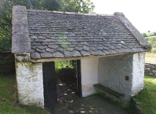

 54(a)
Photos Terry Hughes
54(a)
Photos Terry Hughes
45 SPAB Slating in Wales and the Marches
54(b). 54(c) 54(e)54(d) 54(f)
In horizontal valleys the lead is laid underneath the eaves slates. When it needs to be repaired or replaced, the lower courses of slates have to be removed, which is awkward. To avoid this a lead apron can be installed which can be folded back the next time the valley needs repair (see figure 53).

6.3 Verges
Verge slating is finished with either a slight overhang to the gable wall or cladding and a mortar fillet under the slates; an external rafter or barge board; or an abutment (see figure 54(a) and 21(a)). Barge boards, although common, are not a vernacular detail. The slating is often raised slightly by setting up the rafter, packing up the laths or bedding up the slates to direct water away from the verge or abutment and back onto the roof slope (see figure 54(b) and video 8).
Slating is often finished against a raised outer leaf of the gable wall, sometimes below a cope (see figure 54(c)) and sealed with a mortar fillet. Probably inherited from thatching, when applied to slating, it is a weak detail susceptible to leaks. To overcome this lead soakers are commonly incorporated during reslating but this is not effective in all cases because dampness can still penetrate through the raised wall or butted cope joints.

Verges are susceptible to wind damage. Localised techniques to overcome this include, bedding stones onto the slates (see figure 54(d)). In the slate quarrying regions sawn slabs or small rough blocks were used; (see figure 54(d) and 54(e)) and in north Wales 90°
ridge tiles were popular. The similar technique - fixing a verge board over the slates - is a later innovation. Today, plastic verge covers are being used increasingly, even on completely secure modern slating. They are unnecessary and are not appropriate for historic roofs. Listed building consent would be needed for plastic fascias and is unlikely to be given.
Often there is very little upstand between the slates and the coping so, if the roof is raised, for example, to accommodate insulation, it may be impossible to weather the junction without recourse to a secret valley (see 6.7.8}.
Where there are external rafters, they, and any exposed purlin ends, are often protected with barge slates (see figure 55) and are sometimes decoratively shaped. They are either overlapped by about one-third to protect the nails or butted end to end with the nails exposed or covered with a mortar fillet.
6.4 Abutments
The junctions between the slating and abutting walls and chimneys can be difficult to make watertight. Historically, abutments did not include soakers and relied on mortar fillets which are prone to cracking (see figure 56(a)), or slates bedded in mortar or nailed onto the wall to prevent water penetration (see figures 56(b) and 56(c)). These were often protected by slates set into the wall (see figure 56(d)); and the roof slating might be tilted slightly, by raising the last rafter, packing the laths, or by bedding the slates up on mortar, to direct water away from the junction (see figure 56(e).
Figure 55. Where an external rafter is installed it is often protected with barge slates.
Photo Terry Hughes
Figure 53. For the future, the need to remove the lower course(s) of slates over a horizontal lead valley can be avoided if a lead apron is substituted for the first course.
Illustration Terry Hughes
46 SPAB Slating in Wales and the Marches
56(a)
Figure 56. Abutments are commonly weathered with mortar fillets but they are prone to cracking (a). To help prevent water penetration, slates were bedded over the junction (b) or nailed to the wall and (c)
The abutment was often protected with slates or slabs set into the wall above, which cast water away (d) or by raising the slating (e).


 Photos Terry Hughes
56(e) 56(d) 56(c) 56(b) 47 SPAB Slating in Wales and the Marches
It is possible to conserve the appearance of abutments but to include concealed lead soakers. These and cover flashings became common once lead was economical, but the latter can be visually intrusive and mortar fillets are preferred. The technique of bedding slates into the mortar to prevent cracking is surprisingly rare in the region except in Pembrokeshire and not used at all on stone roofs. When renewing fillets the risk of cracking can be reduced by avoiding hard mortar, by forming the fillet in two or three coats of well-haired mortar or by separating it from the slating and incorporating stainless steel mesh screwed to the masonry joints (see figure 57).

If the roof level is raised, for example, under a label course to accommodate insulation, it can become impossible to form a weather-tight junction except with a secret valley or gutter (see section 6.7.8)


6.5 Ridges
The earliest ridges were finished with a clay or turf capping, by carrying the windward side slates above the opposite slope or with wrestlers (see figure 58).
On metamorphic slate roofs, the 18th and 19th centuries saw the adoption of clay tiles, lead, and less commonly, stone ridges. Patent slate ridges and hips were made by slate quarries (see figure 59) often with decorative crests (see figure 60). Iron foundries also made elaborate ridges, which are a feature of civic

 Figure 57. Cracking of mortar fillets can be reduced by incorporating fibre in the mix or with expanded metal reinforcement.
Photo Terry Hughes
Figure 58. Wrestler ridge on a shed at Kennixton Farmhouse from Llangennith, Gower, Glamorgan. Now at St Fagans museum, Cardiff.
Photo terry Hughes
Figure 60. Decorative crests for “Patent’ ridges.
Photo Terry Hughes
Figure 59. One- and two-piece ridges and hips were frequently claimed to be ‘patented.
Photo Terry Hughes
Figure 57. Cracking of mortar fillets can be reduced by incorporating fibre in the mix or with expanded metal reinforcement.
Photo Terry Hughes
Figure 58. Wrestler ridge on a shed at Kennixton Farmhouse from Llangennith, Gower, Glamorgan. Now at St Fagans museum, Cardiff.
Photo terry Hughes
Figure 60. Decorative crests for “Patent’ ridges.
Photo Terry Hughes
Figure 59. One- and two-piece ridges and hips were frequently claimed to be ‘patented.
Photo Terry Hughes
48 SPAB Slating in Wales and the Marches
buildings in the region (see figure 61). Stone roofs are usually finished with stone ridges cut from freestone (see figure 62). For all these ridge types, new pieces to replace any broken sections can be manufactured to order
Clay and stone ridge tiles should be backbedded in mortar which should not show at the long edges as far as possible. They should not be pointed (see figure 63). The butt joints of plain ridge tiles were weathered with small slate slips (see figure 64).

Where dormer ridges run into the main slating, the slates and the ridge tile are swept up into the main slope (see figure 65) or the junction is weathered with an upturned ridge tile, or today, with a lead saddle.

Under lead ridges or aprons and over the lower
No mortar showing along ridge line
Back bedding
Figure 63. Ridges should always be back-bedded (f) and should not be pointed along the long edges. Ideally, they should not show mortar under the long edge but this is not always possible if the ridge is uneven.

Figure 65 Before the use of lead saddles, the difficult junction between a dormer ridge and the main slope was weathered by sweeping the slates and the ridge up into it.
Photo Terry Hughes
Figure 66. Under lead ridges or aprons, the heads of top course slates must be supported on a thicker batten and ideally, nailed as low as possible (see video 9)


Photo Terry Hughes
 Figure 62. Stone ridges (b) were also made in single pieces from freestone.
Photo Terry Hughes
Figure 61 .Cast iron ridge on Chester town hall. Photo John Greenough,
Figure 64. The butt joints of plain ridge tiles were weathered with small slate slips.
Photo Terry Hughes
SPAB Slating in Wales and the Marches
Illustration Terry Hughes
Figure 62. Stone ridges (b) were also made in single pieces from freestone.
Photo Terry Hughes
Figure 61 .Cast iron ridge on Chester town hall. Photo John Greenough,
Figure 64. The butt joints of plain ridge tiles were weathered with small slate slips.
Photo Terry Hughes
SPAB Slating in Wales and the Marches
Illustration Terry Hughes
49
slope of mansard roofs, the top course of lightweight slates must be properly supported to resist wind uplift (see figure 66 and video 9)

6.6 Hips
Before lead and ridge tiles became commonly available hip slates were mitred and bedded on clay or mortar. Today the mitre is normally weathered with lead soakers. If the adjacent slopes have unequal pitches it is good practice to adjust the gauging and hence the margins so that they course across the hip (see figure 67) but this may not have been traditional practice. Provided the hip is water tight the original detail can be reinstated.

Cut slates on mitred hips are vulnerable to wind damage, so to reduce this risk wider slates were selected for the raking cut (see figure 68). Alternative wind-resistant options

are to cover the hip with lead or clay tile, stone, slate or cast-iron ridges. (see figures 69 and 70) The latter three can all be made to order.
6.7 Valleys
6.7.1 General
The difficulty of making a watertight valley has been tackled with ingenuity, especially before the ready availability of lead for soakers. Various methods, sometimes bedded in clay or mortar, have been used in the past and these add to the character of the building. There is no reason why they cannot be replicated when reslating a roof.
The examples given here and their region of use may be incomplete. Several variations have been recorded in north and mid Wales over recent years, and further research is needed. The types traditionally used and the regions where they have been recorded are shown in Table 6. In the stone slate regions, the valley type is dictated by the stone’s properties. The larger or thicker stones, such as Pennant, Hereford sandstone and the Tilestones do not suit curves or sweeps, so Welsh valleys are
SPAB Slating in Wales and the Marches
 Figure 67. On unevenly-pitched mitred hips the gauging and/or the slate length can be adjusted on the steeper pitch to match the margins on the lower pitch so that they course across.
Illustration Terry Hughes
Figure 68. Wide slates are used on mitred hips to reduce the risk of wind damage. Hereford stone on St Mary’s church, Kempley
Photo Terry Hughes
Figure 69. Slate ridges were equally suitable for hips. Photo Terry Hughes
Figure 70. Cast iron hip at Bridge Street, Dolgellau.. Photo Terry Hughes
Figure 67. On unevenly-pitched mitred hips the gauging and/or the slate length can be adjusted on the steeper pitch to match the margins on the lower pitch so that they course across.
Illustration Terry Hughes
Figure 68. Wide slates are used on mitred hips to reduce the risk of wind damage. Hereford stone on St Mary’s church, Kempley
Photo Terry Hughes
Figure 69. Slate ridges were equally suitable for hips. Photo Terry Hughes
Figure 70. Cast iron hip at Bridge Street, Dolgellau.. Photo Terry Hughes
50
typical (see video 10). The thinner Silurian and Ordovician stones, but not Harnage, can be laid to curves and may be formed to single cut or swept valleys, as well as the more common Welsh type.
There are many subtleties in the way vernacular valleys are constructed. Each type will work only with their traditional lapping system (see figure 71(a)).
To perform well, valleys have to deal with some constraints: the narrowness of small vernacular slates; their limited range of lengths; and, as is normal for all valleys, the fact that the valley rafter is longer than the common rafters. A variety of valley types tackle these issues in different ways. Also, besides the way the slates are arranged in each type, there are some techniques which are applied more generally. These are:
• The phenomenon whereby water clings to the edges of the slates. Advantage of this is taken by shaping the slates to a point, to direct the flow of water to where it will not leak into the roof; usually, onto the centre of a slate below. Chevrons and shales are examples of this technique.
• The use of shales, small pieces of slate which cover or underlay gaps in the slating. They are always shaped with a point at the bottom and placed so the point directs water onto the slate below.
• Tilting slates at a valley so that water running down the roof is turned away from the vulnerable junction (see the video in 6.7.5).
Valleys can be classified in two main types.
Those that carry the slating across the junction in the same curved plane - swept and collarand-tie, for example - and those where the valley slates are set below the main areas on either side with the main slating laid over them - the Welsh valley is one example. There is also at least one hybrid where only one side is over laid - the single cut.
Welsh, single cut valleys and shale all tilt the slating on either side of the intersection to turn water away from the vulnerable area. They do this by offsetting the valley board and/or by the slates overlying each other. In a single cut valley for example, the cut side slates are tilted because they lie on top of the swept side slates.
A valley rafter is longer than the common rafters. So, if the slating is to course across the valley in the same plan, longer slates are needed in the valley so that there will be the same number of courses and the margins will be the same height. If there is a wide range of slate lengths in the consignment, the longer ones can be selected for the valley. But some small quarries supplied slates in just a few lengths and only a few of the longer ones. So a roof would have maybe two or three courses of 16 and 14 inch (405 and 355 mm) long slates, and the rest of the roof could be all 12 inch (305 mm). In this case, where the slates available for the valley do not fit the intended gauge perfectly, the valley slates are gauged for the required head lap and the gauge of the slating on both main areas is decreased to suit. In this way, the main areas which would otherwise be slated in thirds might become
Valley type Slate or stone Locality Swept Slate Mid-Wales Mitred slate-lined Slate North Wales Collar and tie Slate Pembrokeshire Shale Slate North Wales Single cut Slate Mid-Wales and Marches Welsh Both Mid- and south Wales, Marches Welsh mitred Slate North Wales Mitred lead-lined Slate Not vernacular but common as Open lead-lined Both replacements of traditional valleys Table 6. Traditional valley types and their known locations 51 SPAB Slating in Wales and the Marches
three-and-a-half pin; because the gauge has been reduced.
Lead-lined valleys are not vernacular and laced slate valleys are not traditional in Wales (see 10.5 Hughes 2019).
More information and videos of valley construction can be seen here
6.7.2 Swept valleys
Swept valleys of the Cotswold type are not common in Wales (see figure 71(b)). Normally, these valleys are formed by selecting longer and wider slates from the stock and dressing them to taper from head to tail (see figure 71(c)) or selecting suitably shaped ones. Many Welsh vernacular slates were narrow and supplied in just two or three lengths so they could not be dressed to a wide enough inverted triangle, or provide the necessary head lap in the valley without reducing the gauge on both slopes which would be costly. Where they are seen, they use many narrow slates to get round the intersection, eight or more compared with three and four slates wide in alternate courses, for example, in the Cotswolds.
6.7.3 Collar and tie valleys
Collar and tie valleys are more common in south-west England than in Wales where they are known only from Pembrokeshire (see figure 71(c)).
The valley slates are longer than the main slates which compensates for their narrowness. These are a swept valley type but they work differently from conventional swept valleys, and to be effective the roof has to be set out for at least slating in thirds.
Alternate courses are close mitred (the collars) and swept (the ties). The joints in the close mitred (collar) courses are weathered by the slate in the next course down. The central slates in the tie courses need to be even longer than is simply needed, to ensure the margins match, so that they are triple lapped. So even if their very narrow side laps leak, there is an extra slate underneath to catch the water and carry it back out of the slating. Also of note, the
tails of the tie slates are cut to carry water away from the mitre junction in the course below (see video 11).
6.7.4 Shale valleys
Shale valleys are very complicated and require great skill. It is essential that the main slating is set out for three-and-a-half pin gauge for the valley to work. The valley is built up in three layers: a wood valley board; a lining of chevron shaped slates laid single lapped on the board; and the valley slates (also chevron shaped) on the linings with shales interleaved between them (see figure 72(a)).
The lining slates raise the main slates on either side, turning water away from the valley. They also carry any condensation or water that might get through the valley slates down the valley and out at the bottom.
These valleys tackle the narrow slate problem in a different way. The valleys are only a few slates wide and are laid in the same way as a swept valley, but they overcome the problem of the gap at their top corners by inserting shales between the slates at their shoulders. These are pointed to direct any water onto the valley slate below (see video 12).
Surface tension at the chevron edges of the lining and valley slates holds any water that reaches them, and directs it to the point at the bottom and onto the centre of the slate below. This is an effective way of controlling the movement of water and preventing leaks into the roof (see video 13).
6.7.5 Welsh or double-cut valleys
Seen in slate over most of mid and eastern Wales and in stone in south Wales, the Forest of Dean and Herefordshire, Welsh or doublecut valleys, are best suited to roofs where the intersecting slopes are of equal pitch or no more than 15° different. The whole valley is in effect a narrow roof laid in the same way as the main slating, but with longer slates than those on the adjacent slopes. The slates on either side lap onto the valley slates by about 180 mm (7 inches) for a typical pitch of more that 35° and consequently are tipped up slightly to direct water away from the valley (see figures
Slating in Wales and
52 SPAB
the Marches
71(a)
71(c)
71(d)
Figure 71
In valleys where the slating course across the intersection (swept, shale and collar and tie for example) they will work only at their traditional gauge. In (a) the slating is laid at three-and-half pin, producing margins of 2/7ths of the slates’ lengths and is essential for the the shale valley shown in 72(b).


Swept valleys are not common in Wales and where they do exist they reuire a wide sweep to work with the generally narrow slates produced in many Welsh quarries (b). They contrast with the Cotswolds swept valleys, where wide slates (c) are plentiful and can be formed to work well in sets of two and three slates in alternate courses (b).
Collar and tie valleys (c) need very long slates centrally to prevent leaks.

 Photos Terry Hughes
71(b)
53 SPAB Slating in Wales and the Marches
Figure 72
In shale valleys (a) the vulnerable gap at the top corners of the chevron-shaped valley slates (C) and the main slates (M )are weathered with shales (S). The left shale is arranged with the main slate and the valley slate, so that any water reaching it is directed via the point onto the shale and chevron in the next course below.
Welsh valleys in Hereford stone (b) and slate (c). Like single-cut and shale valleys, because the main slates overlie the valley slates, water is turned away from the vulnerable junction.

In a variation on the Welsh valley the slates from either side are mitred on the centre line (d)


 Photos Terry Hughes
.
72(a). 72(c). 72(d). 72(b). 54 SPAB Slating in Wales and the Marches
72(b) and 72(c)). Provided the slating in each is appropriately lapped and the overlap of the sides over the valley is adequate, they work perfectly.
There is a variation on the Welsh valley where the slates from either side are mitred on the centre line (see figure72(d)). Because they look like an modern mitred valley externally, they may be common but unrecognised (see video 14).
6.7.6 Single-cut valleys
Single-cut or half swept valleys are suitable for roofs where the intersecting slopes’ pitches differ by more than 15°. The valley boards are offset to the steeper or longer side which carries the most water (see figure 73).
The slates on the lower or shorter pitch are swept up under those on the other side, so that they and the offset of the board tilts the overlying slates, directing water onto the main slating parallel to the valley (see figures 74(a), 74(b) and video 15).


On the swept side the slating dips before sweeping across, which also directs water away from the valley line (see figure 74(c) and video 16). Also the side laps are set to be wider down the tilt, to compensate for the diagonal flow of water.
Figure 74.
In single cut valleys water is turned away from the junction by tilting the slates on both sides.
 74(a)
Figure 73. Succesful valleys often combine the kill of the joiner (a) and the Figure 66.slater (b). Working together they ensure that water flowing over the slating moves away from the vulnerable junction (c)
Photos Terry Hughes
Photos Terry Hughes 74(c)
74(b)
74(a)
Figure 73. Succesful valleys often combine the kill of the joiner (a) and the Figure 66.slater (b). Working together they ensure that water flowing over the slating moves away from the vulnerable junction (c)
Photos Terry Hughes
Photos Terry Hughes 74(c)
74(b)
55 SPAB Slating in Wales and the Marches
6.7.7
Close-mitred and open valleys
In Tremerchion near Denbigh there is what is probably a precursor to the modern leadlined mitred valley. Instead of lead the lining is parallel-sided chevron-shaped slates (see figure 75(a) and video 17). These are singlelapped and are not interleaved with the main slating, so they carry water all the way down to the eave rather than directing it back out onto the main slating like lead soakers.


Although now common, lead-lined valleys are not vernacular and are included here only for completeness (see figures 75(b) and 75(c)). They are not an appropriate replacement for the vernacular valleys described above.
6.7.8 Secret valleys, secret gutters
At abutments if a mortar-flaunched junction
75(a)
75(b)
Figure 75
A close-mitred slate lined valley in Tremerchion, Denbighshire (a). These may be more common than realised because the slate lining is not visible until the valley is dismantled.
Lead-lined open (b) and close-mitred (c) valleys are not traditional and should not be substituted for vernacular types.
Photos Terry Hughes
75(c)
56 SPAB Slating in Wales and the Marches
76(a)
76(b).
76(c)
Figure 76
Secret valleys and gutters can be closed (a) or open (b).
The former always become blocked eventually and leak.
The latter are more visually intrusive especially if lead lined. The slate lined version near Corwen may be more visually acceptable.
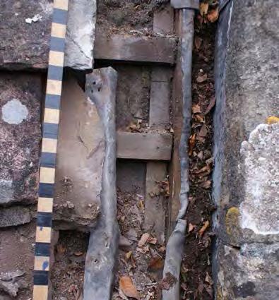

Photos Terry Hughes
Figure 77 The inclusion of a lead apron when renewing a horizontal valley will avoid having to strip the slating next time it has to be done.
Illustration Terry Hughes.
cannot be formed it may be necessary to introduce a secret or hidden valley - usually a consequence of raising the roof surface to introduce insulation. These are prone to block with leaves and other debris, so it is essential to establish a maintenance plan to keep them clear (see figure 76(a)); ideally in the autumn after leaf fall. The slating can be carried tight up to the wall or held back. The former reduces but does not eliminate debris getting in and are more difficult to clear. The latter are easier to clear, but more visually intrusive. It is possible to form the valley at the original level over the gable wall (where insulation is required) and lay slates in the valley (see figure 76(b)).
6.7.9 Horizontal valleys
Lead-lined horizontal valleys are likely to need to be repaired or renewed sooner than the slate or stone roofs which discharge onto them. This usually means removing the lower courses of slating, but this can be avoided in future if a lead apron is included which can be folded back to renew the valley lead. (see figure77). A sacrificial apron can also be included.
6.7.10 Authentic reslating
All of the vernacular valleys described here were originally constructed in response to the available sizes of slates in their locality. They work with those sizes but usually cannot with other sizes (see figure 78). So to correctly relay and conserve them, the same slates must be used. If a roof with a swept valley laid to work with narrow slates is relaid in wide tally slates, simply because that is the default slate that a quarry makes today, then it will be impossible to conserve the valley, because these slates will not lie down tightly into the curve.
6.8 Dormers and rooflights
Dormer windows are uncommon in older buildings in Wales. Where they do exist, it is often

57 SPAB Slating in Wales and the Marches
78(a).
Figure 78
78(b).
Reslating valleys. If large modern slates are used instead of the original small (random) sizes they will not sit down into the curve of coursed valleys. The consequence so often is to install a lead valley instead (a) and the original roof is lost completely - wrong slates, wrong detail and probably the wrong slater.


In coursed valleys (b) if long slates are not used to allow for the longer valley rafter, the valley slating will always lag behind the main areas going up the roof. To match the coursing and margins of the main slating to the valley, it will need to curve down towards the valley slates on each side, with the result that the valley will look as though it has sagged. This is a bad mistake, which is easily avoided as described in section 6.7.1.
the result of the adaptation of the roof space for domestic or workshops use, which may coincide with a change from thatch to slate. Sometimes this may have involved raising the walls or altering a couple or truss to provide head room (see figure 79).

The earliest, 18th-century, dormers are small and low or only partly within the roof expressing the low-ceilinged rooms they illuminated (see figures 80(a and 80(b)). Later windows are larger and

79(a)
Figure 79. Evidence of a raised roof can be seen externally (a) or internally (b). In (a) the former chimney is now encorparated into the raised gable. In the roof (b) the position of the former couple has been raised to provide for a bedroom. In (c) a third floor has been added above the former eaves line, probably for a home workshop.
79(b)
79(c)
Photos Cadw and Terry Hughes
Photos Terry Hughes
SPAB Slating in Wales and the Marches
58
placed higher in the walls or entirely in the roof (see figure 81).

Mono-pitched and gabled dormers are common in slate and stone but hipped versions are rare (see figure 82). Cheeks are either rendered or slateclad but very rarely stone clad. On ridged dormers, before the general availability of lead, ridges were swept up into the main slating (see figure 68) or the junction was weathered with an upturned ridge tile. Where lead was available a saddle weathers the junction.


Bell vents and ventilation louvres are similar in style but are also sometimes lead-covered (see figure 83(a) and 83(b))
Rooflights are an alternative to dormers and, being much cheaper to install, are common on industrial, farm and similar buildings. They are an
Figure (a) near the Corndon Hill former small roofing quarry south-west of Shrewsbury (b) Finsbury Square, Dolgellau. Demolished in the 1950s. (c) inserted window in a house in Tremerchion, Denbighshire..
Photo (b) Francis Firth Collection www.francisfirth.com remainder Photos Terry Hughes
Figure 80. Early dormer windows are set below (a) or low in the roof (b). Gabled (b) and Mono-pitched version (c) are common.
Figure 81 Dormer placed higher in the roof. Colebatch in Shropshire. Photo Terry Hughes
Figure 82. Hiipped dormer in Arran Road Dolgellau. Photo Terry Hughes
80.(a)
80.(b) 80.(c)
59 SPAB Slating in Wales and the Marches
important feature of many farm buildings. In their simplest form, sheets of glass are substituted for slates or are inserted into the slope and the slating overlaid (see figure 84). Where the extra cost was acceptable cast iron lights were used. They are usually quite small (see figure 85).


The scale of the rooflights in relation to the roof slope is an important consideration in roof renewal. If an existing light cannot be reused, the replacement should be of similar size and style. ‘Conservation rooflights’ will generally be preferable, and should be of slender section steel with a vertical emphasis. These lie flush and emulate the look of traditional cast iron. Bespoke sizes can be made where rooflights of standard dimensions are unsuitable. The use of excessive flashings between the rooflight and roof should be avoided to maintain the character of the building.
6.9 Limewash
It is a long-standing tradition to limewash buildings including the roof (see figure 86). This may seem a trivial aspect of roofing but it is important to an understanding of a roof’s history and affects its performance and longevity.

For roofs, the original purpose was probably to protect thatch against both natural deterioration and fire, and its continuation on later slate roofs may be simply tradition and a matter of pride in a building’s appearance. Limewashing was done annually and has been associated with the culture at the beginning of the yearly agricultural cycle in spring and especially as a preparation for Easter. Also, farm buildings and dairies were limewashed inside and out for reasons of hygiene
 83(b).
Figure 83. Sound vent. St Mary’s church Kempley, Gloucestershire (a), Herefordshire. Dovecott=e in Richard’s Castle, Shropshire (b).
Photo Terry Hughes 83(a)
Figure 85. Original rooflights were generally small and low profile, making a small impact on the appearance of the roof.
Photo Terry Hughes
Figure 84. Farm buildings are often lit with sheets of glass which replace slates.
Photo Terry Hughes
83(b).
Figure 83. Sound vent. St Mary’s church Kempley, Gloucestershire (a), Herefordshire. Dovecott=e in Richard’s Castle, Shropshire (b).
Photo Terry Hughes 83(a)
Figure 85. Original rooflights were generally small and low profile, making a small impact on the appearance of the roof.
Photo Terry Hughes
Figure 84. Farm buildings are often lit with sheets of glass which replace slates.
Photo Terry Hughes
60 SPAB Slating in Wales and the Marches
but other than this it has no technical purpose for a roof until the roof is failing, when it becomes slurrying. The technique was to make a thick mix of quicklime and water in a bucket and apply it with a brush (https://youtu.be/s-JZjdCC7xs). It has become confused with slurrying, described below.
The white buildings and especially the white roofs, are an important landscape feature in Pembrokeshire, where its continuation and even conservation is supported (see figure 87).
Attempts to replicate the roofs’ appearance using lime mortar have not always been successful, probably because it was applied in one thick coat rather than several built-up over time. The more recent, unauthentic, use of cement mortar did not fail in itself provided a suitable mix was used - but there are many renewed roofs where a poor mix has fallen off except for the ribs (see figure 88). Also, the result is a grey rather than a bright white roof, so it fails in that objective too.
If white roofs are to continue to be a landscape feature, building owners will have to be persuaded or made to limewash their roofs and to do so every few years.
In regions other than Pembrokeshire where limewashing was recorded as a significant feature of the landscape in the past, it seems to have been largely unremarked for conservation and allowed to gradually disappear as roofs were reslated.
6.10 Uses of mortar
Mortar has many traditional uses in roofing and is applied at different stages of roofing work or during the life of the roof. They include bedding slates at the tail or head, torching the underside, pointing at verges, flaunching at abutments, and grouting.
The word grouting can mean forcing mortar or a sealant under the slates’ tails or into the perpendicular joints ,or it can mean a thin layer of mortar applied to the roof’s surface. To distinguish between these two, applying mortar to the surface is described below as slurrying.
6.10.1 Bedding
Bedding is applied as the slates are laid. In the region it is usually applied at their heads. Tail-bedding is uncommon except perhaps in Pembrokeshire, where the evidence is unclear
because it is obscured by grouting and slurrying. Careful examination of the mortar and its shape under the slates will be necessary to decide whether a roof was originally tailbedded or grouted later (see figure 89). Headand tail-bedding both stabilise the slates, but head-bedding also secures the pegs in their holes (see figure 90). Tail-bedding risks trapping water behind the slates, so it is safer to apply a small dab rather than a bed right across the slate and up the perpendicular joint.
The techniques are important for smaller slates because their heads often do not lie closely onto the laths, especially in the upper courses where the head lap is a larger proportion of the length. If a slate’s head does not touch the lath, the wind can lift its tail, resulting in rattle and eventually it falls off. Head-bedding was not intended to draught-proof a roof, although it may do so.
Head-bedding and torching are compatible but neither should extend too far down between the slates because of the risk of external moisture reaching the laths, leading to rotting and leaks. It is also dangerous to apply tail- and head-bedding together for the same reason - they may touch when the slates are pressed down. Anyway, there is no reason to do both together.
Where it was applied originally, bedding is a necessary part of the slating and should always be reinstated when a roof is repaired authentically. It is also essential for the conservation of the historic appearance of the underside. It is not necessary to omit bedding simply so that an underlay can be substituted.
6.10.2 Vaulting
Some vaulted roofs are covered with slating bedded directly onto the masonry without a timber structure. There are several examples in Pembrokeshire.
6.10.3 Torching
Torching is applied once the slating is complete to prevent draughts and powdery snow blowing into the roof (see figure 91). It is applied to the underside of the slates and may be a single coat of lime mortar which has been left rough, or in two coats, and may just
61 SPAB Slating in Wales and the Marches
.
Figure 87. Slurried roofs, such as these at Abereiddy, are an important landscape feature in Pembrokeshire. Although formerly common in many exposed regions of Wales, they have not been conserved in the same way as in Pembrokeshire


86(c)
Figure 88. Confusion about the technique of slurrying, and the suitability of different mortars, has resulted in roofs rapidly loosing their slurry with only the ribs remaining. Rhodiad-ybrenin.
Photo Terry Hughes
Figure 86. There is a long history of limewashing roofs, but the original purpose has become confused with efforts to prolong the life of failing slating by grouting and slurrying. (a) Limewashing for decoration on a roof with tail bedded slates, Aberdaron, Gwynedd in 1875. Slurried roofs in (b) Pembrokeshire today and (c) in Aberdaron, 1875
Photo (a) and (c) Llyfrgell Genedlaethol Cymru – The National Library of Wales (b)Terry Hughes
Photo Terry Hughes
86(b) 86(a)
62 SPAB Slating in Wales and the Marches
cover the top of the slates (single-torching) or their backs completely between the laths (full-torching). If a second coat is applied covering the laths and pegs, it may be trowelled to form a tidy ceiling. It is very important that torching is not forced too far down between the slates, to avoid drawing water to the laths and rafters.
Both domestic and agricultural buildings are found with two-coat work, which indicates its importance. It became more common in houses when roof spaces were adapted for accommodation or home workshops. In shippons, or cow houses, it was used because cattle will not tolerate drips.

It can be reapplied during re-slating, but there may be some areas which are now inaccessible, for example, at the eaves, because the ceiling is in the way. Head-bedding should be used in those areas instead.
6.10.4 Grouting
The term grouting can mean forcing mortar into a crack or a void or applying a thin coating (slurrying) to a surface. Both are applied long after the construction of the roof. Slurrying is described below.
Forcing mortar, or today, some sort of sealant or mastic under the slates and/or into the perpendicular joints appears to be done for two reasons: to prevent draughts on a roof without bedding, torching or underlay; or over a gable wall below a chimney where the inside of the wall is wet and it is assumed, incorrectly, that the roof is leaking (see figure 92). The latter is actually caused either because the wall has been cement mortar rendered or because of hygroscopic salts which leak into the wall’s plaster from unlined chimney flues. These absorb water and release it later when the atmospheric conditions change, producing damp patches along the line of the flue.
Also, where slates have slipped, they are often temporarily repaired by bedding them onto mortar. This will not last. It is better to refix the slate properly (see 7.2) or if this isn’t possible to hang the slate on a copper tingle.


Grouting is unlikely to be necessary when reslating.
6.10.5 Slurrying
Slurries of various mortars, based on lime or cement, are applied all over a roof. Slurrying is seen throughout west Wales, especially near the coast and in exposed upland areas (see figure 93). This process was no different from, and almost certainly a continuation of, decorative limewashing described above, and it would have been applied in the same way, by brushing on. However, its purpose is different. Where poor durability slates are failing (often the case in Pembrokeshire) or the fixings are failing and slates are slipping, it is used to keep the roof going for
Figure 89. Tail bedding is applied as the slates are laid and should not spread beyond the tail onto the slate below. Pointing, grouting and slurrying are applied long after the slating was laid. Pointing and grouting are spread along the slates tails and forced up under the slate. Slurrying is spread all over the slates. Pembrokeshire.
Photo Terry Hughes
Figure 90. Head bedding is applied as the slates are laid.
Photo Terry Hughes
Figure 91. Two coat torching in a cow shed. Photo Terry Hughes
63 SPAB Slating in Wales and the Marches
a bit longer. It is only a temporary solution and inevitably has to be repeated frequently - typically, annually. And that is what finally brings about the roof’s demise. The increasing weight of slurry eventually overwhelms the slate, or the lath fixings, and large areas become detached (see figures 12(a) and 94). To prevent the roof covering falling away entirely, lengths of barbed wire are hung over the roof from eave to ridge to opposite eave, and a mortar fillet rendered over them, producing a distinctive feature (see figures 12(b) and 95).
This technique today has become conflated with the limewash tradition described above. Slurrying is primarily a temporary repair and so, when a roof finally fails, the logical step is to renew the slating and apply slurrying only if and when it is needed in the future. But this will not conserve the white roofs because the original poor durability slates are no longer available, either new or as reclaimed. And who would choose to use them today anyway? And those slates which are manufactured will last very much longer - a hundred years or more. To slurry a new slate roof is understandably unpopular with the building owners, and has been a contentious issue in the past.
6.11 Farm buildings
These tend to remain unaltered for long periods and are often the best source of information on early roof structures and slating techniques. Their detailing is less elaborate than in domestic buildings and this should be respected in repairs. Verges and eaves often have little overhang and gutters are seldom included. Lighting for storage areas or livestock was not important, so it was often provided by replacing a few slates with glass (see figure 84) or by installing small cast iron rooflights rather than dormer windows (see figure 85). Good ventilation is important for livestock, but this was usually provided by openings in walls rather than roofs or by raising a few ridge tiles.
7 Maintenance
7.1 Deterioration
Slate roof deterioration is usually a long-term process and, even though repairs can be carried out for many years, routine maintenance will significantly delay the need to strip and re-slate. The key is to check often, perhaps twice a year,


Figure 92. Mastic grouting in an ill-conceived attempt to prevent damp walls. Near Caernarfon.
Photo Terry Hughes
inside and out if at all possible, and to act quickly. An unattended leak can result in timber rotting or other fabric damage which will seriously exceed the cost of repairs. It is particularly important to keep rainwater gutters - especially horizontal lead gutters - and downpipes clear of debris.
Insulation is also a potential source of dampness because it can cause moist air to condense onto woodwork so it should not be assumed that dampness always indicates a slating problem.
7.2 Repairs
Missing, slipped or broken slates should be replaced as soon as possible. If they are pegged it will probably be possible to lift or rotate adjacent slates, to slide a new slate of similar thickness into place. However, this will break any torching, so this should be replaced as well. If the slates are nailed, then a slater’s ripper should be used to cut or drag out the nail. The replacement can be fixed with a peg or copper tingle (see figure 19). For repairs to large areas a triangle of slates should be stripped so that all except the apex can be re-fixed with
Figure 93. Slurried roof at Rhosgadfan, near Caernarfon.
Photos Terry Hughes
64 SPAB Slating in Wales and the Marches
pegs or nails and only the top one(s) will need a tingle or similar fixing.
7.3 Mortar
Where long-established mortar bedding is crumbling or falling away it can be repointed, but this is usually only a temporary reprieve, as the lath nails are probably failing as well and repointing places more stress on them.
Slurrying roofs is a policy of last resort. Although it is traditional in the region it is not a good technique, because it can eventually cause the complete failure of the roof, with collapsed battens and rotting of the structure and will be far more costly to repair than reslating. When the battens
fail, large areas of slating will slip. At this point the roof will be beyond practical repair, and should be stripped and reslated.
Fallen torching should be renewed, because it holds pegs in place, helps prevent slates being lifted by high winds and protects laths from water damage. Ridge and hip tiles may need re-bedding and, if the bed is not exposed along the edges, an NHL 3.5 mortar is suitable. Where it is exposed it will need to be stronger, an NHL 5, for example, or the NHL 3.5 bedding mix can be pointed-up.
7.4 Bi-annual checklist
Twice a year:
• Check internally for water-staining or other signs of leaks. These may be much lower on the roof than the leak.
• Clear gutters and downpipes, pitched and horizontal valleys and secret gutters.
• Replace slipped, broken or missing slates.
• Check if ridges and hips are secure.
• Check leadwork – look for wrinkles and cracks, cuts from slipped slates and flashings coming out of chases.
• See whether mortar beds, fillets or flaunchings are cracking or insecure.
• Look for leaks around roof penetrations such as rooflights or solar panels.
• Ensure insulation is not blocking ventilation routes, for example, at the eaves or ridge.

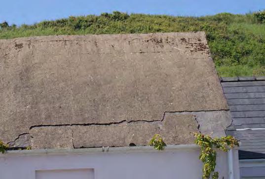 Figure 94. Eventually the weight of slurries overcomes their adhesion, and large sections fall away. Pembrokeshire.
Photo Terry Hughes
Figure 95. Reinforcing ribs on a Pembrokeshire roof. Photo Terry Hughes
SPAB
Figure 94. Eventually the weight of slurries overcomes their adhesion, and large sections fall away. Pembrokeshire.
Photo Terry Hughes
Figure 95. Reinforcing ribs on a Pembrokeshire roof. Photo Terry Hughes
SPAB
65
Slating in Wales and the Marches
National Vocational Qualifications
The Level 3 NVQ Diploma Roof slating and Tiling and construction site management (conservation). Successful completion entitles candidates to apply for the Construction Skills Certification Scheme (CSCS) Gold Card covering craft skill, job knowledge and understanding. They can extend this with the Level 3 Heritage Special Apprenticeship Programme for Roof Slating and Tiling. This covers the historical, theoretical and technical knowledge and practical skills in historic building conservation, repair and restoration which
9 Video links
The
Section Page Topic
1
1.2
4.3
4.6
5.1
lead to the CSCS Card endorsement Heritage Skills. These are the appropriate qualifications for slaters who work on historic roofs, especially those in random slates. There are similar systems for construction site management of conservation work and for conservation
Thermal performance
Historic England has published a series of guides on compliance with Part L Conservation of fuel and power generally and for roofs (see 10.5 Historic England 2016). CADW has not published its own guide, but recommends using the Historic England guides.
Video link
https://vimeo.com/channels/spabwelshslating/455181486
https://vimeo.com/channels/spabwelshslating/441544639
https://vimeo.com/channels/spabwelshslating/441959219
https://vimeo.com/channels/spabwelshslating/441949200
https://vimeo.com/channels/spabwelshslating/439956741
https://vimeo.com/channels/spabwelshslating/453197671
https://vimeo.com/channels/spabwelshslating/442334568
https://www.youtube.com/channel/UCNeM10EH7n5r3LQxwIl38Yw
https://vimeo.com/channels/spabwelshslating/443654802
https://vimeo.com/channels/spabwelshslating/443965108
https://vimeo.com/channels/spabwelshslating/452816845
https://vimeo.com/channels/spabwelshslating/453190042
https://vimeo.com/channels/spabwelshslating/452986149
https://vimeo.com/channels/spabwelshslating/444489893
https://vimeo.com/channels/spabwelshslating/452816845
https://vimeo.com/channels/spabwelshslating/452800401
https://vimeo.com/channels/spabwelshslating/443652699
https://vimeo.com/channels/spabwelshslating/453000731
8 References
66 SPAB Slating in Wales and the Marches
4 0 Terminology
8 1 Gauging in thirds
20 2 Making Patent slates
24 3 Peg fixing
4.6 24 4 Torching
4.6 24 5 Head bedding
33 6 Dressing slates
5.12 43 7 Cladding
6.3 46 8 Abutment water
6.5 49 9 Secure top courses
6.7.1 50 10 Welsh Valley
6.7.3 52 11 Collar & tie valley
6.7.4 52 12 Shale valley
6.7.4 52 13 Surface tension
6.7.5 55 14 Welsh valley
6.7.6 55 15 Single cut valley
6.7.6 55 16 Single cut water flow
6.7.7 55 17 Chevron valley
videos can be seen here or individually below.
10 Other advice
10.1 Consultants and contractors
Where slating work is being considered, the SPAB may be able to suggest the names of suitable contractors and professionals or advise on courses that teach practical skills. Local authorities may also have lists of architects, surveyors and slaters with experience in local slating.
The names of professionals accredited in building conservation be obtained from the relevant accreditation bodies:
• Architects (AABC Register) www.aabc-register.co.uk/
• Building Surveyors (ConservationAccredited) www.rics.org/
• Structural Engineers (Conservation Accreditation Register for Engineers) www.istructe.org
• The names of contractors accredited in heritage roofing can be obtained from: The National Federation of Roofing Contractors 020 7638 7663 www.nfrc.co.uk/heritage-roof-specialists
10.2 Slate and stone slate producers
Slates
• The Traditional Slate Company 07771 552321
enquiries@thetraditionalslatecompany.co.uk www.traditionalslatecompany.co.uk
• Welsh Slate Ltd, Penrhyn Quarry, Bethesda, Bangor, Gwynedd LL57 4YG 01248 600656
enquiries@welshslate.com www.welshslate.com
Stone slates
• Hay Stone Coed Major Farm, Craswell, Herefordshire HR2 0PX 07773 778118
enquiries@hay-stone.com https://hay-stone.com
• Hereford Sandstone Supplies Ltd Springfield, Longtown, Hereford HR2 0NA 07814 220657 herefordshiresandstone@yahoo.co.uk
10.3 Advice on conservation
• Cadw Plas Carew, Unit 5/7 Cefn Coed, Parc Nantgarw, Cardiff CF15 7QQ 0300 0256000 cadw@gov.wales https://cadw.gov.wales
• Historic England Midlands, The Axis, 10 Holliday Street, Birmingham B1 1TF 0121 625 6888 midlands@HistoricEngland.org.uk https://historicengland.org.uk/about/contact-us/ local-offices/midlands/
• Stone Roofing Association tech@slateroof.co.uk www.stoneroof.org.uk
10.4 Advice on protection of animals and plants
• Natural England 0300 060 3900 www.gov.uk/government/organisations/naturalengland
• The Bat Conservation Trust 0345 1300 228 http://www.bats.org.uk/
• The Barn Owl Trust 01364 653026 www.barnowltrust.org.uk
10.5 Further reading
Allen, G, Allen, J, Elton, N, Farey, M, Holmes, S, Livesey, P and Radonjic, M (2003) Hydraulic Lime Mortar for Stone, Brick and Block Masonry, Shaftesbury: Donhead Publishing Ltd
Barclay, W J, Davies, J R, Hillier, R D, and Waters, R A, (2015) Lithostratigraphy of the Old Red Sandstone successions of the Anglo-Welsh Basin. Research Report, RR/14/02, Keyworth, British Geological Survey.
SPAB Slating in Wales and the Marches
67
Bennet, F and Pinion, A, (1948) Roof Slating and Tiling, 2nd edition, London: Caxton Publishing Co. Reprint 2000, Shaftesbury: Donhead Publishing Ltd
Boutwood, J., (1991), The Repair of Timber Frames and Roofs, SPAB Technical Pamphlet 12, London: Society for the Protection of Ancient Buildings.
British Standards Institution (2011 + A1:2016) BS BS 5250:2011+A1:2016 Code of practice for control of condensation in buildings, London: British Standards Institution
British Standards Institution (2014) BS EN 12326-1:2014 Slate and Stone Products for Discontinuous Roofing and Cladding, London: British Standards Institution
British Standards Institution (2014) BS 5534:2014 + A2:2018 Slating and Tiling for Pitched Roofs and Vertical Cladding: Code of Practice, London: British Standards Institution
British Standards Institution (2015) BS EN 4591:2015 Building Lime: Definitions, Specifications and Conformity Criteria, London: British Standards Institution
Building Regulations (2018) Building Regulations 2010: Approved Document L1A: Conservation of Fuel and Power in Existing Dwellings (2010 Edition Incorporating 2010, 2011, 2013, 2016 and 2018 Amendments – For Use in England). Available at: https://www.planningportal.co.uk/ info/200135/approved_documents/74/ part_l_-_conservation_of_fuel_and_power/2 (Accessed 11 March 2019)
Building Regulations (2016) Approved Document L2B: Conservation of Fuel and Power in Existing Buildings Other than Dwellings (2010 Edition Incorporating 2010, 2011, 2013 and 2016 Amendments – For Use in England). Available at: https://www.planningportal.co.uk/ info/200135/approved_documents/74/ part_l_-_conservation_of_fuel_and_power/4 (Accessed 11 March 2019)
Cadw Best Practice Guidance for Listed Buildings in Wales. Available at:
https://cadw.gov.wales/advice-support/ historic-assets/listed-buildings/best-practiceguidance#section-managing-change-to-listedbuildings-in-wales (Accessed 23 March 2020)
https://cadw.gov.wales/sites/default/ files/2019-05/20170531Managing%20 Change%20to%20Listed%20Buildings%20 in%20Wales%2024303%20EN.pdf (Acessed 16 September 2020)
Davey, N, (1971) A History of Building Materials, London: Phoenix House Ltd.
Emerton, G, (2017) The Pattern of Traditional Roofing, Acton, Nantwich CW5 8LE
https://spark.adobe.com/page/Bkar9XFoe ao2c/?ref=https%3A%2F%2Fspark.adobe. (Accessed 6 September 2020)
English Heritage, (2003) Research Transactions vol 9 Stone Roofing in England Swindon: English Heritage. Available at: http://www.stoneroof.org.uk/historic/Historic_ Roofs/Publications_files/EH%20Trans%209%20 Stone%20Roofing%20LR.pdf (Accessed 2 April 2020)
English Heritage, (2013) Practical Building Conservation: Roofing, Farnham: Ashgate Publishing Ltd.
Gwyn, D (2015) Welsh Slate: Archaeology and History of an Industry, Aberystwyth: Commission on the Ancient and Historic Monuments of Wales. There are very many other books about the history and operation of individual Welsh slate quarries.
Health and Safety Executive, Construction micro-organisms: Anthrax from contaminated land and buildings. Available at: www.hse.gov.uk/construction/healthrisks/ hazardous-substances/harmful-microorganisms/anthrax.htm (Accessed 30 March 2020)
Historic England (English Heritage) (2005) Stone Slate Roofing Technical Advice Note, London and Swindon: Historic England. It is being revised and expanded to also cover metamorphic slating for publication in 2020. Available at:
SPAB Slating
68
in Wales and the Marches
https://historicengland.org.uk/advice/ technical-advice/buildings/building-materialsfor-historic-buildings/stone-slate-roofing/ (Accessed 2 April 2020).
Historic England (2016) Energy Efficiency: Insulating Pitched Roofs at Ceiling Level, v1.1, London and Swindon: Historic England. Available at:
https://historicengland.org.uk/images-books/ publications/eehb-insulating-pitched-roofsceiling-level-cold-roofs (Accessed 5 Sept 2020)
Historic England (2016a) Energy Efficiency and Historic Buildings, v1.2, London and Swindon: Historic England. Available at:
https://historicengland.org.uk/images-books/ publications/eehb-how-to-improve-energyefficiency (Accessed 5 Sept 2020)
Historic England (2016) Energy Efficiency: Insulating Pitched Roofs at Rafter Level, v1.3, London and Swindon: Historic England. Available at
https://historicengland.org.uk/images-books/ publications/eehb-insulating-pitched-roofsrafter-level-warm-roofs (Accessed 5 Sept 2020)
Historic England (2020) Building Stone Database for England, London: English Heritage. Rebranded 2017, London and Swindon: Historic England. Available at: https://www.bgs.ac.uk/mineralsuk/ buildingStones/StrategicStoneStudy/EH_ project.html (Accessed 5 Sept 2020)
Holmes, S and Wingate, M (2002) Building with Lime: A Practical Introduction, 2nd edition, London: ITDG Publishing
Hughes, H and North, H L (1908) The Old Cottages of Snowdonia, reprinted (1979) Snowdonia National Park Society, Capel Curig.
Hughes, T G (1997-2020) Historic Roofs in Britain and Ireland [Online]. Available at: http://www.stoneroof.org.uk/historic/Historic_ Roofs/Introduction.html (Accessed 21 March 2020)
Hughes, T G, (2003) ‘Stone Roofing in England’ in Wood, C (ed) Stone Roofing: Conserving the
Materials and Practice of Traditional Stone Slate Roofing in England, English Heritage Research Transactions – Volume 9, London: James & James (Science Publishers) Ltd. Available at: http://www.stoneroof.org.uk/historic/Historic_ Roofs/Publications_files/EH%20Trans%209%20 Stone%20Roofing%20LR.pdf (Accessed 14 May 2020)
Hughes T G (2012) Patent Slating in Historic Roofs in Britain and Ireland [Online] Available at:
www.stoneroof.org.uk/historic/Historic_Roofs/ Patent_slating.html (Accessed 30 March 2020)
Hughes, T G (2016) A Glossary of Slate and Stone Roofing [Online]. Available at: www.stoneroof.org.uk/historic/Historic_Roofs/ Publications_files/Glossary%20v3%205-16.pdf (Accessed 21 March 2020)
Hughes, T G, and Jordan, R, (2016) Slating in South West England. London: Society for the Protection of Ancient Buildings. Available at: https://www.spab.org.uk/sites/default/files/ SPAB%20Technical%20advice%20noteSlating%20in%20South%20West%20England. pdf (Accessed 30 March 2020)
Hughes T G and Jordan R, (2019) Vernacular Slating in the East Midlands, London: Society for the Protection of Ancient Buildings. Available at: https://www.spab.org.uk/sites/default/files/ SPAB%20Technical%20advice%20noteVernacular%20Slating%20in%20East%20 Midlands.pdf (Accessed 5 Sept 2020)
Hughes T G (2020) Patent Slating in Building Conservation Directory 2020, Tisbury: Cathedral Communications. Available at: https://www.buildingconservation.com/ articles/patent-slating/patent-slating.html (Accessed 30 March 2020)
Hughes T G (2020) Historic roofing in Britain and Ireland - Valleys. Available at http://www.stoneroof.org.uk/historic/Historic_ Roofs/Valleys.html (Accessed 12 July 2020)
69 SPAB Slating in Wales and the Marches
Hughes, P (2020) The Need for Old Buildings to Breathe, London: Society for the Protection of Ancient Buildings. Available at:
www.spab.org.uk/sites/default/files/NFOBTB-_ reduced_1.pdf (Accessed 11 May 2020)
Locke, P (1990) Timber Treatment: A Warning About the Defrassing of Timbers, SPAB Information Sheet 2, London: Society for the Protection of Ancient Buildings
National House-Buildings Council, Slates - No more grey areas. NHBC, Milton Keynes
National Federation of Roofing Contractors NFRC guide TB4A Selecting Natural Slates for Roof Covering London: NFRC
National Federation of Roofing Contractors, (2009) Guidance Sheet E Slater’s Heel London: NFRC. Available at:
https://www.nfrc.co.uk/docs/default-source/ health-and-safety-guidance-publications/ healthsafetyguidancesheets/hs-guidancesheet-e---slaters-heel---feb-2009.pdf?sfvrsn=2 (Accessed 13 May 2020)
National Federation of Roofing Contractors, (2009) Guidance Sheet M Working at Height London: NFRC
National Federation of Roofing Contractors, (2012) Technical Bulletin TB03 Hooks for Slating London: NFRC
National Federation of Roofing Contractors (2013) Fall Protection and Prevention for Working on Roofs, Health and Safety Guidance Sheet A, London: National Federation of Roofing Contractors.
Peate I C (1940) The Welsh House, Reprinted (2004) Lampeter: Llanerch Press
Richards A J (1991) Gazetteer of the Welsh Slate Industry, Llanrwst: Gwasg Carreg Gwalch He has also written many guides to slate production in Welsh regions.
Roach P (2005) The White Roofs of the St Davids Peninsula, in Coulson M R, (ed) Stone in Wales, Cardiff: Cadw.
Slocombe M (2017) The SPAB Approach to the Conservation and Repair of Old Buildings, London: Society for the Protection of Ancient Buildings. Available at:
https://www.spab.org.uk/campaigning/spabapproach (Accessed 5 Sept 2020)
Smith P (1975) Houses of the Welsh Countryside, London: HMSO.
SPAB The Manifesto of the Society for the Protection of Ancient Buildings, London: Society for the Protection of Ancient Buildings.
SPAB (2014) Energy Efficiency in Old Buildings, London: Society for the Protection of Ancient Buildings.
Available at: www.spab.org.uk/sites/default/files/ documents/MainSociety/SPAB%20Briefing_ Energy%20efficiency.pdf (Accessed 11 May 2020)
SPAB Roof maintentance. Available at: www.spab.org.uk/advice/roof-maintenance (Accessed 12 May 2020)
Sugget R and Dunn M (2014) Discovering the Historic Houses of Snowdonia, Aberystwyth: Commission on the Ancient and Historic Monuments of Wales. This deals mainly with the historical evolution of house types rather than roofs.
Sugget, R (2005) Houses and History in the March of Wales: Radnorshire 1400-1800, Aberystwyth: Commission on the Ancient and Historic Monuments of Wales.
Tucker, T and Tucker M (1979) The Slate industry of Pembrokeshire and its Borders in Industrial Archaeology Review Vol 3 Issue 3 pp203-227
William, E (1982) Traditional Farm Buildings in North-East Wales 1550 - 1900, Caerffili: National Museum of Wales, Welsh Folk Museum.
William, E (1986) The Historical Farm Buildings of Wales, Edinburgh: John Donald.
SPAB Slating in Wales and the
70
Marches
William, E (2010) The Welsh Cottage, Aberystwyth: Royal Commision on the Ancient and Historic Monuments of Wales.
Wood C (1999a) Reroofing Pitchford Church in English Heritage Conservation Bulletin 36, London: English Heritage. Available at:
www.stoneroof.org.uk/historic/Historic_Roofs/ Pitchford_Church.html (Accessed 30 March 2020)
Wood, C (1999b) Reroofing Pitchford Church in English Heritage Transactions – Volume 9, London: James & James (Science Publishers) Ltd. Available at:
http://www.stoneroof.org.uk/historic/Historic_ Roofs/Publications_files/EH%20Trans%209%20 Stone%20Roofing%20LR.pdf (Accessed 14 May 2020)
71 SPAB Slating in Wales and the Marches
The content of this publication is offered in good faith, but neither the authors nor the Society can accept responsibility arising from incorrect or incomplete information that may be included. The use of traditional materials may incur risks that are different from those associated with modern materials. Manufacturers’ and suppliers’ guidelines should always be observed. This document is intended as a contribution to a continuing debate and we welcome comments.
Written by Terry Hughes and Richard Jordan. The authors are indebted for help from Stephen Parry on the stratigraphy of stone slates, Stafford Holmes on mortars, the SPAB Technical and Research Committee, Douglas Kent and Catherine Peacock for their help with the preparation of the document and Judith Rodden for proof reading. The sources of illustrations are given adjacent to them together with any copyright where not belonging to the SPAB.
The Society for the Protection of Ancient Buildings (SPAB) believes old buildings have a future. From cottages to castles and from churches to cathedrals we are here to help buildings and the people who care for them. Through our unique training schemes, courses, advice and research we help people put our expertise into practice.
Today the SPAB encourages excellence in repair and good new design to enrich and complement the built historic environment. We train new generations of architectural professionals and building craftspeople to conserve this landscape with sensitivity and skill, and we play a statutory role as adviser to local planning authorities. In our casework we campaign actively to protect old buildings at risk.
SPAB: hands on history. Join today to support our positive, practical approach to building conservation.
Published by the SPAB in September 2020
© Terry Hughes/SPAB 2020
SPAB ref T5503M www.spab.org.uk
ISBN 978-1-898856-467
The Society for the Protection of Ancient Buildings
37 Spital Square, London E1 6DY
Tel 020 7377 1644 info@spab.org.uk www.spab.org.uk
A charitable company limited by guarantee registered in England and Wales Company No 5743962
Charity No 111 3753
VAT No 577 4276 02
Vernacular Slating in the East Midlands

SPAB Regional Technical Advice Note
Terry Hughes BSc (Hons), FIoR Dp Man
Richard Jordan FIoR SPAB William Morris Craft Fellow
37 Spital
London E1 6DY
020 7377 1644
info@spab.org.uk
www.spab.org.uk

The Society for the Protection of Ancient Buildings
Square
Contents
This Advice Note describes the production and use of the roofing slates and stones of the East Midlands of England. It includes the metamorphic Swithland slates, the Jurassic limestonesCollyweston slates and similar stones from the Northampton and Banbury area - and briefly, the Magnesian limestones. It deals with the maintenance and repair of roofs, considers details specific to the traditions of roofing in the region and explains, where appropriate, adaptations to incorporate modern requirements, such as improved thermal performance.
1 Introduction
2 Recording and assessment
3 Work in general
4 Repairs and reslating
5 Specification and detailing
6 Random slating
7 Swithland slating
8 Limestone slating
9 Magnesian Limestone slating
10 Collyweston slating
11 Northampton slating
12 Maintenance
13 References
14 Other advice
3 6 10 13 18 23 25 28 31 32 36 38 38 40
Cover image: Swithland slating near Leicester. The house was reslated in 2003.
Photo: Terry Hughes
SPAB Vernacular Slating in the East Midlands2
....................
.....................
....................
....................
....................
....................
....................
....................
....................
....................
....................
....................
....................
....................
1 Introduction
In the roofscape of the English Midlands, which is otherwise dominated by tiles and Welsh slates, four areas still display vernacular stone roofs: Swithland slate in and around Leicester; Magnesian limestones to a small extent between Mansfield and Doncaster; Collyweston stone slate near Stamford in Lincolnshire but used over a much wider area, even as far away as New York state, USA; and other Jurassic stones in the Northampton area.
The products of small quarries and mines, these slates are all random-sized with distinctive features and are formed into roofs with characteristic techniques which are regionally important.
Swithland slate is a true metamorphic slate of Cambrian age (Swithland Formation). Fissile beds of limestone were worked in the Magnesian Limestone (Cadeby Formation), the Middle Lias, Northampton Sand and Lincolnshire Limestone Formations, and the Great Oolite Group (see table 1); some were split by natural frost action.
Formation Stone slate sources
Oxford Clay
Kellaways sand and clay
Cornbrash
Great Oolite Group
Blisworth Limestone*
Rutland Formation (Upper Estuarine Series)
Oundle (possibly Yardley Chase)
Pytchley, Hoping Hill, Helmdon, Kettering, Wellingborough, Northampton, Duston
Jurassic
Lincolnshire Limestone Formation
Upper Lower (Collyweston Slate)
Grantham, Formation (Lower Estuarine Series)
Northampton Sand Formation
Variable Beds
Ironstone
Wothorpe, Burghley Park, Wittering, Collyweston, Duddington, Deene Park
Duston, Harlestone, Pitsford, Weston Favell
Middle Lias Sulgrave, Chacombe, Banbury Permian Magnesium Limestone
Cadeby Formation
Table 1: Historical sources of stone slates in the East Midlands
* Blisworth Limestone is known locally as Oundle limestone
Specialised slate and stone roofs are rare. Indeed, some types may have disappeared long ago, but they are important to the history of local economies and cultural heritage, and wherever they still exist they should be carefully conserved. They are major elements in the character of historic buildings and settlements, and help give individual buildings, towns and villages their sense of place.
Steetley, Bakestone Moor, Whitwell (possibly Worksop)
This is in part due to the materials themselves, with their different colours, textures and sizes, but also to the way in which they are laid and detailed.
This Advice Note explains the basics of Swithland, Collyweston and other limestone slating practices and the local variations (see boxouts on ‘Terminology’ and ‘Dimensions’).
Slating
SPAB Vernacular
in the East Midlands3
Terminology
Technical terms used in this guidance and not explained in the text are defined in our online glossary and that of the Stone Roofing Association.1 The meanings of some words are variable and need to be understood before reading on:
Slate: Strictly, this term should be applied only to stones derived from sediments which have undergone low-grade metamorphism – the process of compression and heating under which the sedimentary minerals are recrystallised and reorientated perpendicular to the compression. They can be split into thin, strong and flexible sheets which are not parallel to the original sedimentary bedding layers. In practice, where the specific type of rock is not relevant or is obvious, the term slate can be used to mean other roofing stones, such as shales, limestones or sandstones.
Shales: These are splittable rocks which have not undergone metamorphism, or less so than true slates.
Stone slates: A commonly used but geologically deprecated term for splittable sedimentary rocks. In geology texts, the term tilestone is often used instead.
Cleavage: The property of true slates which allows them to be split. Also a verb, to cleave. In quarries, the synonyms rive or riving are also common (see figure 1).
Fissile, fissility: The property of sedimentary stones which allows them to be split along bedding planes (see figure 1). In Collyweston, the fissile stone is known as log.
Random slates: Slates with a variety of lengths and widths often sold by weight. They are usually described in the form longest to shortest lengths in inches by random width, for example, 24 – 12 x R.
Tally slates: All slates in a consignment or on a roof of the same length and width sold by count.
Slate length: The length of slates sold by quarries is the overall dimension from the tail to the head (bottom edge to top edge). However, for top-fixed slates – all the slates in this Advice Note – the effective length is the dimension from the tail to the bottom of the fixing hole and this is typically 25 mm (or 1") less than the overall length (see figure 2). This is important, because it is the length to the fixing hole which is used to establish the gauging of the roof and hence the area that can be covered with a given quantity of slates. Failure to appreciate this can result in expensive underestimates of the cost of a roof. When carrying out random roof surveys or recording, it is the length to the fixing hole which should be measured.
Gauge: The spacing of laths or battens up the roof slope. In random slating, the gauge is variable and is proportional to the slate length. There is more than one system:
• Proportionation: Any system for setting out the slating – gauging the laths or battens – in which the gauge is determined by dividing the slate length by a number. This is usually done with a slater’s stick (see boxout in section 6.1 on ‘Using a slater’s marking stick to gauge a roof’). Examples of proportioning include dividing by three – slating in thirds (see figure 3) - or three point five (three-and-a half pin slating).
• Calculating the gauge from a specified head lap using the equation: Gauge = (length – head lap)/2 This is the system universally applied to tally and some random slating.
Dimensions
Although metric dimensions were adopted long ago, many slaters still work in inches and some slate manufacturers still make imperial size slates and quote approximate metric equivalents. In this Advice Note, where past practices are described and where direct quotations are provided from historical documents, the inch dimensions are used. Otherwise, and for descriptions of modern practice, approximate metric equivalents are given with the imperial dimensions in brackets.
SPAB Vernacular Slating in the East Midlands4
Sedimentary rock
Metamorphic rock
Figure 1: Bedding and cleavage. Sandstones and limestones are sedimetary rocks which are fissile along the bedding layers. Metamorphic rocks, such as slates, schists and phylites, have been changed from sediments by pressure and heat in the Earth’s crust. They split along the resultant cleavage planes almost always at an angle to the bedding.


Figure 2: Laps and gauges. Quarries describe and sell slates by their overall length from the head to the tail. The effective length of top-fixed slates is about 1" (25 mm) less because the distance above the fixing hole has to be discounted when setting out the roof. Failure to appreciate this can result in expensive under-estimates of the cost of a roof.
Illustration: Terry Hughes
Illustration: Terry Hughes
Figure 3: Slating in thirds. In the proportioning system slating in thirds, the slate length is divided by three.
Illustration: Terry Hughes
Figure 4: The effective width of head-fixed slates is greater than if they are centre-nailed. Following the introduction of BS 680 roofing slates in 1944, quarries adopted the ‘slate width not less than half the length’ limitation for all slates but this was, in fact, only necessary for centre-fixing. The consequent elimination of the narrower slates traditionally used in scantle slating has changed the appearance of roofs. For the conservation of old roofs, the existing lengths and widths should be recorded and the narrow examples included in the specification and order to the quarry.
Illustration: Terry Hughes

SPAB Vernacular Slating in the East Midlands5
Whilst the slates and stones themselves are durable and may last hundreds of years, the roofs have a finite life determined by the fixings used to support them. Pegs and laths rot and nails rust. Roofs are known that may be between 150 and 200 years old, but there will be very few in situ any older than this. Older buildings may well have had their roofs renewed two, three or more times during their existence, and although the original slates may be salvaged and reused once or twice, the act of stripping and re-laying a roof potentially destroys most of the evidence of the earlier roofing techniques.
It is very important that the details of roofs are recorded before the slating is stripped and that the information obtained is used to formulate appropriate specifications for reslating. Surviving examples are likely to contain valuable information about traditional craft techniques as well as reflecting local variations.
In general, the existing form and details of each historic building should be respected and retained during any campaign of repair. This extends not only to the overall appearance of the building but also to the construction methods employed.
The broad principle of retaining existing details does not mean that they should simply be replicated without thought. There are situations where details may need to be sensitively adapted to improve performance: but, if so, this should follow careful analysis in such a way that the traditional local form and appearance is maintained, along with appropriate statutory consents.
Unfortunately, many roofs are mistakenly deemed to be inadequate even though they have performed satisfactorily for more than 100 years and have reached the point of needing repair only because of iron nail failure. These roofs are simply stripped and discarded with no attempt to understand their construction and detailing. Also, in recent years there has been a tendency to use modern slating recommendations and detailing for historic roofs, as exemplified by British Standards, without regard to visual and technical needs. This is inappropriate for conservation, not least because such modern standards omit vernacular techniques (see boxout on ’Vernacular slates and British Standards’). The issue of differences between modern and historic slating should be dealt with at the design stage of a project.
2 Recording and assessment
2.1 Recording and condition surveys
Any work on a historic roof should always be based on an understanding of the existing construction and how well it has performed. Each surviving example is likely to contain valuable information about historic craft techniques. It is important that the recording of such information is undertaken before the slating is stripped and that the results are used to develop a specification for the reslating. The level of recording entailed should be proportional to the significance of the building. Recording will minimise the possibility of delays and errors in the ordering of any new slates; and, importantly, will give the owner of the building more certainty over the final cost. If no survey is done, assumptions about the quantities of slates needed will have to be made at the time of specifying the work in order to obtain prices.
Where defects occur, they are frequently down to poor maintenance, unsuitable alterations or inadequately sized members, and result in decay or distortion of the roof. It is important to distinguish these factors from inherently poor design or construction.
2.2 Structural deterioration, rafter settlement and deflection
Most historic roofs will have moved during their lives. Commonly, because of inadequate restraint by couples etc, the eaves will have spread, pushing out the walls, and the ridge settled. Rafters may also have settled along their length or adjacent to walls. These features give roofs much of their character and should not be rectified unless there is a clear structural reason to do so.
Some roofs were constructed with a concave upwards curve in the rafters that helps the slates to sit tightly together. This should not be misinterpreted as settlement.
Every effort should be made to conserve the structure that supports the roof covering. The roof structure is frequently one of the least altered parts of an old building and may provide valuable clues about its history. These range from smoke-blackened timbers where
SPAB Vernacular Slating in the East Midlands6
Vernacular slates and British Standards
Durability
Swithland slates
In principle, BS 12326-1, the product standard for metamorphic roofing slates, could be used to test Swithland slates but the test methods (water absorption, thermal cycling and sulfur dioxide exposure) are intended for newly manufactured slate, so reused slates cannot be expected to pass. For reused slates, it is normal to test for soundness by tapping with a hammer and dressing off any softened parts. New facsimile slates or slates from other sources should have a declaration of performance - see box out on 'Metamorphic slate durability' below.
Limestones
There are no formal tests for limestone roofing slates. The best guide to durability of new slates is evidence of successful use of slates from the same source over a long period of time.
Strength
BS EN 12326 requires the bending strength (modulus of rupture) of slates to be tested across, and along, the slate’s long dimensions (longitudinal and transverse orientations) and from this a slate’s minimum individual thickness is calculated. This could be applied to confirm the strength of reused Swithland slates but because they are so thick it is probably pointless.
Grain
Some slate has bending strengths which are significantly different in the longitudinal and transverse directions. This is known as grain. It has nothing to do with surface texture or mineral veins in a slate. BS 680:1944, the former roofing slate standard, required the grain to be longitudinal in the slates (parallel to the long edge). This was to ensure that the maximum strength was in the direction which best resisted loadings on a roof, such as wind forces or roof settlement.
It is not sensible to apply this to all slates. Swithlands have such coarse cleavage that they can only be split so thickly that they have more than adequate strength, irrespective of the grain direction. Other slates have almost equal strength in the two orientations, so they have no grain. Grain orientation is not a requirement in BS 12326-1, although the direction of maximum strength should be declared.
Minimum width
BS 680 also set a limit on the width of slates - they should be no narrower than half their length. This was because the design recommendations for sizes of slates and their minimum head laps, which were set in relation to roof pitch and the rain exposure of the building, assumed the width of the slates. This limit came to be adopted by all slate quarries but not for stone slates (BS 680 did not apply to them anyway) and narrower slates fell out of production.
This limitation also assumed the slates would be centre-fixed, that is, fixed with nails roughly halfway up the slates, one on each side. This had become standard practice for new slating by 1944. However, vernacular slates and stones always were, and still are, head-fixed. The difference this makes for driving rain resistance is that centre-fixing reduces the effective width of the slate by the distance of the nails from the edges - about 25 mm, but this can be larger. Consequently, they are effectively 50 mm narrower than top-fixed (see figure 4) so topfixed slates with widths less than half their length are satisfactory. BS EN 12326-1 does not set a minimum width limit but BS 5534 Code of Practice for Slating and Tiling includes recommendations and a means for calculating minimum widths for top-fixed metamorphic slates.
Other dimensions
BS EN 12326-1 also includes limitations for deviations from length, width, edge straightness, rectangularity and flatness, none of which should be applied to reused Swithland slates or limestones.
Fire and dangerous substances
Swithland slate would be deemed to satisfy fire requirements and, even though BS EN 12326-1 does not apply to them, so would limestone slates. Neither release dangerous substances.
BS5534 Code of Practice for Slating and Tiling
This is primarily a code for new roofing. The scope states: ‘The recommendations contained in this British Standard might not be appropriate for the re-slating or re-tiling of some old roofs, particularly where traditional and/or reclaimed materials are used. Users intending to adopt any of these recommendations for old roofs, and especially for historically or architecturally important buildings, are advised to consult the local planning authority or an appropriate conservation organization to check their suitability.’
SPAB Vernacular Slating in the East Midlands7
an open fire in a medieval hall preceded a chimney, to remnants of early decoration and evidence of smoke bays or louvres. Many old roof structures also constitute fine examples of craftsmanship. Jointing is often exemplary and features such as crown posts, moulded beams and traceried early spandrels may be found.
A technical assessment will frequently indicate that stabilisation of the roof structure is all that is necessary. However, deflection or settlement of the structure may have created undulations in the roof slope which are impossible to slate without gaps, especially for larger slates or stones. In this case, it is acceptable (and essential) to ease the undulations by packing under the laths or similar (see figure 5). Where settlement is less severe, gaps under the slates can be reduced by using narrow slates which will fit more tightly across the undulations.

2.3 Nail failure
Rusting of iron nails used to fix laths or slates is the main cause of slates becoming detached from the roof. Loss of slates individually indicates that it is the slate nails which are failing. This will be a gradual process and they can be refixed for a time. If lath nails fail, several slates in a course will slip.
2.4 Lath failure
Lath failure is indicated by courses of dropped slates or undulations in the roof plane (see figure 6). If the failure is extensive then the roof will need to be reslated. Laths may be unable to carry the weight of the slates if they have been weakened by rot or insect attack.

2.5 Slate failure
All the slates and stones covered by this Advice Note are durable and will reach the end of their lives only after many, commonly hundreds, of years. Typically, the process of slate ageing is a general softening in the overlapping parts of the slates. Less durable slates may fail for three main reasons: the presence of deleterious materials; inherent weakness; or because of mechanical stress (see boxout on ‘Metamorphic slate durability’).
The stone slates covered by this Advice Note which are currently produced are from longestablished mines or quarries.2
SPAB
Vernacular Slating in the East Midlands
Figure 6: If whole courses of slates have slipped, the cause is usually failed lath nails.
Illustration: Ray Harrison
Figure 5: Movement of the roof structure: (a) Distortion may not require any correction or perhaps just needs stabilising. If there are severe or abrupt undulations, though, they can be impossible to slate over without the slates gapping, even if small or narrow slates are used. In this case the undulations can be eased. (b) If undulations are eased only by the minimum necessary to allow tight slating, the special interest of the roof will be conserved.
Photos: Terry Hughes
5(a) 5(b)
8
Metamorphic slate durability
The current standards for roofing slates are BS EN 12326-1 Product Specification and BS EN 12326-2 Methods of Test. They are revised from time to time. BSI and the NFRC can advise on the latest versions. They do not apply to stone slates.
There have been problems with imported slates in recent years. These are caused by inclusions - carbonates (calcite etc) or metallic minerals, collectively known as pyrite or pyrites. They can be present in the slate as distinct crystals or veins or be dispersed within the slate’s structure. When exposed on a roof, expansive reaction take place, converting pyrite to iron oxide and carbonate to bicarbonate or sulfate. These can result in staining, cracking, flaking or blistering of the roofing slate. Some forms of pyrite can be stable so its susceptibility cannot be decided visually. Other failures have been the result of mudstones and siltstones being sold as slates. Some of these disintegrate very quickly on roofs.
Slates should conform to BS EN 12326-1 Product Specification and should be tested by the quarry once a year or for every 25 000 tonnes of finished slates they produce, whichever arises soonest. It is particularly important that they conform to the scope of the standard which defines a slate geologically. Quarries must provide a Declaration of Performance based on the Assessment and Verification of Constancy of Performance (AVCP) of the slate. This was formerly known as a Certificate of Conformity.
Specifiers should be aware that it is not safe to simply specify ‘slates conforming to BS EN 12326-1’. This is because the durability tests in the standard have more than one level of conformity and such a specification allows slate with any of the conformity levels to be supplied. The range of conformity levels was necessary to accommodate all the slates produced throughout Europe, some of which are less durable than is acceptable in the UK market. A specification should state the conformity level for three of the tests: water absorption – less than 0.6% or more than 0.6%; thermal cycling - T1, T2 or T3; and sulfur dioxide exposure - S1, S2 or S3. (Slates in lower categories and with lower water absorption - lower than 0.3% ideally - are the most durable.) There are other tests which need to be considered as well.
Rust-staining indicates the presence of oxidising metallic minerals and a general whitening of the slates will usually be the result of a high carbonate content, although this can also be caused by carbonates leaching out of mortar or by lead-staining. A specialist report will be needed to determine whether the slates already on a roof should be replaced. It is important to understand that although oxidisation of pyrite can be a serious problem (which in recent times has been associated mainly with imported slates) not all pyrite oxidises and some will do so without causing problems.
Slate breakage can be due to wind forces, roof settlement or imposed loads, such as people walking on the roof or, more importantly, because the slates are inherently weak. Wind damage is usually localised on the lee side of hips, ridges or other changes in the roof shape. Broken slates can be replaced individually but if the cause is wind damage a review of the fixing method or slating technique is advisable. Failure due to inherent weakness is usually a symptom of imported slates which are too thin.
A roofing slate’s strength is a function of its thickness and the inherent strength of the rock, known as its modulus of rupture (MoR). Hence an inherently weak rock will only be satisfactory if it is made thicker than one with a higher MoR. BS EN 12326-1 specifies the minimum thickness for slates in relation to their MoR and size. The minimum thickness for specific slates should be declared by the manufacturer.
SPAB Vernacular Slating in the East Midlands9
3 Work in general
3.1 Conservation approach
The demands of conservation impose additional considerations when working on an old building. In particular, a number of overriding principles should be borne in mind when dealing with vernacular slate roofs, in addition to the specific practices described later (sections 4 to 12).
The SPAB exists foremost to promote ‘conservative repair’. For the Society, the value of an old building lies in its antiquity through the mental associations this evokes. It believes that the intrinsic nature of old buildings is best protected by maximising the retention of their historic fabric, while minimising any disturbance affecting their overall integrity.
The SPAB’s view is that conservative repair is achieved by adhering to the following key principles:
• Carry out work essential to the long-term wellbeing of an old building.
• Employ compatible methods and materials.
• Obtain sound information about the history, construction and condition of an old building, as well as user needs, before making any serious interventions.
3.2 Selecting an architect or surveyor
An architect or building surveyor may be employed on larger, more complex projects, or projects where the reslating is only part of the work. This should give the client protection if things go wrong, and a competitive tendering procedure should ensure that value for money is obtained. Professional advisers should be selected who have the right knowledge and experience to specify and inspect the work. For sources of names see section 14.1.
3.3 Selecting a slater or slating company
It is most important to ask skilled and knowledgeable slaters to tender for the work. The primary consideration should be that they take a conservation approach. All too often slaters will strip a roof without looking at its materials, gauging or detailing, and then replace it inappropriately.
contractor is allowed to choose the slater because this, too, may be primarily on the basis of cost. Rather, a shortlist of suitable roofers should be established and within these the key is to ensure parity of tendering and check tenders for completeness. Only then can a choice be made, and it should not necessarily be on the lowest price.
The National Federation of Roofing Contractors operates an accreditation scheme for heritage roofing companies, which includes those working with Swithland slates, and Collyweston and other limestones (see section 14.1). If you intend using an unaccredited company, you should do your own checks for their competence.
There are vocational qualifications (VQs) for roof slating and tiling, and construction site management (conservation) (see table 2).3 These qualifications may be required by clients or be included in grant conditions. The training and tests in roofing VQs are practical in nature but do not encompass conservation per se, and the options selected by trainees on VQ courses may not cover the East Midlands roof types. So even for companies with these qualifications, it would still be wise to confirm and ensure that they will take a conservation approach to the works, and apply authentic techniques and detailing based on an examination of the roof during stripping. For the roofs covered specifically by this Advice Note, the options selected by trainees on VQ courses may not cover Swithland or Collyweston slating.
Older but highly skilled slaters might not have such qualifications, but this should not disqualify them from consideration. A slater should be able to show roofs which they have worked on successfully and provide references. It is wise to view roofs that a company has repaired or reslated, preferably
Roof
Roof
Diploma
Slating
Construction
Construction
It is usually unwise to make a selection based on cost alone, as an inexperienced slater may simply have underestimated the cost after accidentally leaving out a step in the slating process. Problems can also arise if the main Table 2: Vocational qualifications in roofing
SPAB Vernacular Slating in the East Midlands10
VQ title S/VQ level CSCS Card
Slating & Tiling 2 Blue
Slating & Tiling (including random slating) 3 Gold
in Heritage Skills Roof
& Tiling 3 Gold + Heritage skills
Site Supervisor Conservation 3 Gold
Site Management Conservation 6 Platinum Conservation Consultancy 7 Black
recently. Although an external view cannot reveal all the mistakes which may have been made, examples of good workmanship to look out for include:
• Evenly diminishing margins – no margins taller (longer) than ones lower in the slope.
• Tidy mortar – neatly finished at the ridge, hips, verges, abutments and, where appropriate, at the tails of slates.
• Ridge tiles fitting closely onto the slating without thick mortar beds. Roof undulations, curves in the ridge tiles and uneven stone roofing can make it difficult to avoid mortar showing, but it should be minimised.
• In the roof space there should be no signs of leaks or dampness but these would be visible only where underlay is absent.
• Similarly, no tail-bedding mortar should be visible from the underside, only headbedding. Do not confuse either with torching.
The slater should be asked to provide a statement covering all the steps in reslating a roof, including:
• Survey and recording – how the roof will be inspected before and during stripping to ensure historical details will be conserved and technical detailing will be replicated or, if necessary, improved. This may be subcontracted to a specialist surveyor and may have been carried out prior to tendering.
• Specification review – advising on unsuitable or impractical aspects of the specification.
• Method statement – a description of how the work will be organised and executed.
• An explanation, or ideally a demonstration, of how the slating will be set out on the roof (lath gauging). This can be done by demonstrating making the marking rod which will be used on the roof.
• The reslating process – a description of the process of carrying out the work. This aspect is important because comparison between tenderers will highlight any step which has been omitted.
• How they will deal with any faults or damage caused, for example, when dismantling scaffolding.
Quotations should state the total area of the slating work to be done, so that differences can be checked and any aspects which are unknown until the roof is stripped should be clearly explained. It is also very important that
all quotes are based on the correct gauging system.
3.4 Specifications
Any work on historic roofs should always be based on an understanding of the existing roof and how well it has performed. Ideally, a survey to record and photograph the constructional details should be carried out prior to writing the specification. This will involve some opening up of the roof. The survey should cover the general slating; eaves, valley, verge, abutment, hip, ridge and dormer window details; and the slate sizes, condition and gauging. It should also assess whether the roof has performed satisfactorily or deteriorated prematurely because of some inherent defect. Care and experience are needed to differentiate between cause and effect. The survey should be carried out by a slating consultant, experienced contractor, architect or building surveyor.
Based on the survey findings the specification can be prepared. Where modifications are required to fulfil other objectives, such as environmental performance, they should be based on sound information. In particular, care should be taken when insulation is introduced and/or a means of venting any moisture from the batten space is provided. It would be wise to discuss the practical and technical implications of any innovations with the appointed slater before confirming the specification.
This Advice Note includes roof details that vary across the region and which should be replicated during repairs or reslating. In the Northampton area, there is a crossover between Collyweston and Cotswold roofing styles and details, so those which ought to be applied on a particular roof should be based on research, a survey or other reliable information rather than assumptions.
A written specification will allow the work to be detailed and standards of materials and workmanship to be set out, so that all slaters who are pricing the work can do so against the same document. The prices can then be judged on an equal basis. If the work includes more than slating, and is to be managed by a main contractor, a good specification will ensure that the method and standard of slating can be understood by all who tender and can be met by the contractor or slating subcontractor. Under certain contracts, a particular slating firm can be nominated. The specification should cover the following issues:
SPAB Vernacular Slating in the East Midlands11
• Survey and recording, if required.
• Policy on retention of historic details and materials.
• Slate source, size range, thickness.
• Gauging and head lap.
• Side lap (for random slating the requirement is to set perpendicular joints approximately central over the slate below; for larger slates a minimum side lap can be stated).
• Battens or laths and fixings (sizes and materials).
• Slate fixing method (nailed or peg-hung).
• Slate fixings (nails or pegs, sizes and materials).
• Mortar, if required, including any preparation procedures and precautions to ensure satisfactory curing.
• Underlay.
• Insulation and means of ventilation.
• Details for eaves, verges, abutments, hips, valleys, dormer windows and ridges.
3.5 Listed building consent
For listed buildings, most changes to the construction details will require listed building consent from the local authority. Relevant changes include:
• Reslating of a roof at the end of its life, where renewal would affect the building’s character.
• Removal and alteration of material and/ or detail of archaeological or historic importance.
• Alteration of detailing affecting, for example, ridges, valleys, hips, abutments or verges, or the style and size of dormer windows.
• Change from one slate or stone type to any other slate, stone or to clay or concrete tiles, imitation slates or sheet products.
• Use of slate or stone of a different geological type, including another source quarry within a particular geological type.
• Change from riven laths to sawn battens, or the reverse.
• Introduction of counter-battens, which significantly raise the roofline.
• Change of slate fixing method, for instance, top-hung to centre-nailed.
• Change in the overall range of slate lengths, which would significantly affect the roof’s character.
• Use of new slates or stones that have been prepared using non-traditional methods, such as sawn edges which have not been dressed to give a bevelled edge.
• Change of ridge or hip material, such as from one stone type to another or to reconstituted stone, concrete or clay ridges.
• Introduction of building service or ventilation details that would significantly affect the character of the building.
Local policy on these issues should be checked before making proposals for alterations. The policy is likely to cover three main options:
• Completely authentic reslating – an exact replication of the existing style and techniques.
• External appearance authentic, but modern methods adopted; for example, nailing rather than peg-hanging.
• Either of the other two, but including modern innovations such as insulation.
The third option is most likely to be driven by building regulations.
3.6 Building regulations and other controls on roofing work
In addition to listed building consent, or - for many places of worship - a faculty, building regulations approval will be required for any increase or decrease in the weight of the roof covering.
Where more than 25% of the roof area is to be replaced, the person intending to do the work has a legal obligation to contact the local authority building control department in relation to the upgrading of insulation to comply with Part L of the Building Regulations 2010 (see section 4.8).
All bats and some birds and plants which live on, or in, roofs are protected. This will often limit the time of year when work can be done. The county wildlife trusts will be able to advise, and other sources of information are given in section 14.4. Currently, only BS 747 1F bitumen roofing felt is permitted in roofs where bats are present.
With fully-bedded roofs, such as those of Collyweston slates, bats will not be able to enter unless the mortar has fallen away. However, if access is necessary for small bats, it is possible to leave small areas of the tail-bedding open.
SPAB Vernacular Slating in the East Midlands12
4 Repairs and reslating
4.1 Alteration of details
It is normally assumed that a like-for-like repair or reslating – same slates, same gauging, same bedding, if originally used, etc – will perform satisfactorily in the future. However, the implications of the recent increasing incidence of deluge rain and more severe storm force winds should be considered in deciding on the gauging and fixing method. An improved specification can usually be adopted without an impact on the appearance of the roof, but specialist advice may be needed so that all the implications of changes are taken into account and an integrated solution achieved. Simply applying the recommendations for each element in isolation is unlikely to be successful.
4.2 Structural repairs
All roofwork should be carried out from a safe means of access that does not damage the roof.⁴ Scaffolds should be designed to carry the weight of stacked slates or stones, and with a wide area to allow sorting and redressing. Otherwise, the slates will need to be taken to the ground for sorting.
It is better to repair rather than replace roof timbers. Consult a suitably experienced structural engineer where necessary (the SPAB may be able to suggest names) and leave only minor repairs to the roofer. While conventional carpentry techniques alone will frequently be suitable, strengthening using stainless steel may be justified where it allows more timber to be retained than would otherwise be possible. Resins and consolidants should be used with great care, and other means of reinforcement, such as plastic rods, should be employed only where they can be justified.⁵
Keeping roof spaces clear of rubbish and debris discourages decay. Where active decay exists, the first priority is to eliminate the causes of dampness and promote drying. Chemical treatments are frequently unnecessary and should only be used judiciously where justified as a secondary measure, for example, when it is difficult to reduce moisture levels sufficiently.
Degraded surface material should not be removed (defrassed) without good reason.⁶ Serious mutilation can result. Timbers may be vacuumed or brushed down, though take care
not to remove any medieval smoke-blackening or evidence of early decoration that is of archaeological value.
4.3 Slates
Although slate roofs which are reaching the end of their lives can be kept weathertight for many years by regular maintenance, eventually they will have to be stripped and reslated - typically when 5-10% of the slates have slipped or been lost. The decision to reslate is often precipitated by the repeated cost of scaffolding for repairs.
When carrying out repairs the primary aim must be to retain the maximum amount of historic fabric without compromising the effectiveness of the roof. The existing slates should be reused where they are still sound or, if they are damaged or softened, they may be dressed down to remove any defective areas. They are then sorted into length sets and the number of courses of each length can be calculated.
The individuality of these roofs derives from the mix of slate sizes. Historically, no attempt was made to supply a specific mix of sizes and this policy should be respected for most reslating work today. How the slates were positioned and the detailing was mainly a response to the climate.
Only slates from local sources can produce an authentic appearance. Slates from other locations should not be used unless there is no local source, and only after careful assessment of their suitability and durability.⁷
For extensive reslating, new slates should be used to make up any shortfall and supplied in a mix of sizes as they arise in the quarry or mine. This may be local authority policy and a condition for any grant-supported works. Claims of unavailability or long delivery times should always be checked with the quarries. It may be worth delaying the project for a few months until the right slates can be produced, since the life of a well-slated roof is likely to be in excess of 100 years.
If slates need to be specially made, the producer will need a detailed specification as to what is required and almost always time to organise production. An order might include sizes, quantities, colour, texture and, most importantly, the date the work is to commence and, for large projects, the scheduling for each stage. It is always wise to discuss the order and programme of work well in advance. If a roof is to be stripped and reslated, there will inevitably be uncertainty about the quantities of slates
SPAB Vernacular Slating in the East Midlands13
needed until the numbers of reusable slates are known. Experienced slaters or independent consultants can advise on this before stripping commences.
Only where it is impossible to obtain suitable new slates should the use of slates reclaimed from other buildings be considered, and this should always be from a known source to discourage theft. Reclaimed slates will not last as long as new, and their use inevitably means some other building will have lost its historic roof. Often, they are sourced from several other roofs, so their remaining life will be mixed. They should be checked for softening and damage, especially around the fixing holes. Affected areas can be dressed off but this may result in a shortage of the longer sizes, with a consequent change in the appearance of a roof. It is better aesthetically and for reasons of durability to consolidate old slates onto one or more slopes and to use the new ones on others.
4.4 Slate repairs
The thickness and size of missing or damaged slates must be determined and matched, and this will probably involve opening up the slating.
If the slates are head-fixed, it may be possible to swing adjacent slates aside to hang the new ones.
Where Swithland slates are centre-nailed (which is not traditional), a triangle of slates should be removed so that each one can be accessed for refixing and the last one slid up and fixed with a tingle. Inevitably, any head-bedding, tailbedding for Collywestons or torching will be damaged and this should be renewed.
Collyweston roofs are always wet-laid, ie tailbedded in mortar (see section 10.7). This will
deteriorate eventually and need to be renewed. It is possible to rake out the old mortar and point in new, but this is a stopgap repair that will need to be repeated within ten years.
4.5 Lath and batten fixings
Lath nails should be no less durable than galvanised or Sherardised and sized to suit the laths or battens. Stainless steel nails are sometimes specified, especially in marine situations, but not all types are equally durable. There have been failures associated with AISI Grade 304 in coastal areas, and current advice is to avoid this grade for roofs and use only Grade 316.⁸
Small nails will be needed for fixing thin riven laths to avoid splitting them or the laths can be pre-drilled. Alternatively, cleats (cooper’s hooks) can be used (see figures 7 and 8).
For 50 x 25 mm softwood battens, a 3.35 mm shank diameter is recommended in BS 5534. Shank length and diameter should be chosen to provide adequate pullout resistance for the building’s situation, height etc.⁹
4.6 Slate fixings
The traditional fixings for wet- or dry-laid slates were soft- or hardwood pegs. They were roughly square in section, whittled to a slight taper and forced into the hole until almost flush with the surface of the slate.
On a pegged roof where the underside is to be visible, wooden pegs should be used and are prevented from twisting or falling out by the addition of a small dab of mortar on top (pin pointing) or by torching. Otherwise, nails can be used in the same way as pegs.

 Figure 7: Cleats, also known as cooper’s hooks, can be made by blacksmiths or nail manufacturers.
Photo: Terry Hughes
Figure 8: Cleats support the whole width of a lath and hence the weight of heavy slates. llustration: Ray Harrison
Figure 7: Cleats, also known as cooper’s hooks, can be made by blacksmiths or nail manufacturers.
Photo: Terry Hughes
Figure 8: Cleats support the whole width of a lath and hence the weight of heavy slates. llustration: Ray Harrison
SPAB Vernacular Slating in the East Midlands14
Where wood or metal pegs are used over underlay they must not be so long as to risk puncturing it, especially close to the rafters. Counter-battens may be necessary to prevent this but these can create other problems at abutments etc.
For slate nailing, copper nails are the most durable option. Aluminium nails are also suitable but should be avoided where they might be in contact with lime mortar. Ringshanked nails should not be used for slating, because it will be impossible to remove the slates for reuse in the future without breaking them. Although suitable for fixing laths and battens, stainless steel nails are too smooth to provide adequate pullout resistance for the slates themselves in most situations.
BS 5534 recommends 3.35 mm shank diameter copper nails, in part to ensure an adequate head diameter of 10 mm (3 x the shank diameter). If a thinner nail is necessary, 3.00 mm shank copper nails are available to order with 10 mm heads. The nail length should provide a minimum of 15 mm penetration into the batten in addition to the thickness of the slate(s). BS 5534 provides model calculations for determining slate nail dimensions for adequate pullout resistance.
Hook-fixing is not traditional and should not be used on old roofs.
4.7 Laths, battens and sarking boards
Historically, riven laths were used for all types of slating and are satisfactory for peg-hanging all the slating types in this Advice Note. Made from a variety of woods, including oak and sweet chestnut, they are typically 25 mm wide by at least 6 mm thick and 900 to 1 800 mm long. They are available from specialist suppliers. Being riven, they are not uniform and impart undulations to the slating, which gives a more lively and less mechanical appearance to the roof. Also, they are less prone to beetle attack than sawn battens. For small peg-fixed slates, battens need to be narrower near the ridge to allow space to insert the pegs between them as the gauge reduces.
Formal guidance for slating, such as BS 5534, recommends thicker battens of 50 x 25 mm, which are regarded as providing a safe platform for slaters to work on. If riven laths are used, a risk assessment may be needed to justify their use. Alternatively, a cripple or slater’s heel is a suitable working platform.10 Changing from riven laths to thicker sawn battens will raise the roof level and may lead to problems at abutments and verges. Listed building consent
will be required where a building is listed.
Slating was commonly fixed directly to sarking boards and these should be retained wherever possible. They fulfil most of the functions of underlay in keeping out draughts, powdery snow and dust, reducing the wind uplift force acting on the slates and forming a moisture buffer.
Under correctly laid slating there is no need to include an underlay over boarding and its addition will reduce the ventilation of moisture from the roof space. Even the addition of a vapour permeable membrane will lead to a lower the rate of ventilation of moisture than the presence of no membrane at all. To ensure ventilation through the boards, they can be laid with penny gaps.
If an underlay is needed to provide temporary weather protection it can be removed as slating progresses.
4.8 Insulation and ventilation
Vernacular roofs were built with inherently good ventilation, which prevented moisture build-up and condensation in all but the most adverse conditions. This is one of the main reasons such roofs have survived for so long. Underlays were not included in old roofs and draughtproofing was provided by lime mortar torching. This would temporarily absorb moisture and release it when the weather was more favourable.
Part L of the Building Regulations 2010 requires the addition of roof insulation for most substantial repairs to habitable or heated buildings, including partial reslating. The threshold for ‘substantial’ is 25% of the roof repaired or replaced. However, listed buildings, buildings in conservation areas, scheduled monuments, places of worship and most unheated non-domestic buildings are exempt.11
Installing insulation can increase the condensation risk in the roof structure and affect other parts of the building unless precautions are taken.12
It will be difficult for many older buildings to achieve statutory target U-values without compromising their appearance and it may be impossible. Part L allows for exemptions and special consideration for historic buildings to enable building control officers to take a sensible view in order to conserve the appearance and character of the building and not introduce technical risks.13
SPAB Vernacular Slating in the East Midlands15
To prevent condensation problems, the first step should always be to reduce the amount of moisture reaching the roof. This has two aspects: elimination at source, especially for bathrooms and kitchens; and the installation of a vapour control layer at the top floor ceiling or at the rafters. To be effective, a vapour control layer must be sealed at all joints, perimeters and penetrations, but this can be very difficult as a retrofit.
Having minimised the moisture reaching the roof space, it is important to ventilate any that does. This can be done with eaves, high-level or ridge ventilators, or with vapour-permeable membranes. Ventilation product manufacturers provide guidance on the amount of ventilation required and the levels their products achieve under ideal conditions. Where Agrément Certificates are available, they should always be checked for the limitations applying to their products. For example, many vapourpermeable membranes will only achieve adequate performance provided a vapour control layer is installed below the roof.
It is preferable to place insulation at ceiling level rather than in the rafter depth, because it is easier to provide ventilation through the roof space via eaves to eaves, eaves to ridge or through gable walls. However, this may be undesirable where there is a historic ceiling or lining.
Providing ventilation for insulation placed in, or above, the rafters can involve raising the slating on counter-battens, leading to problems of detailing and changes to the building’s appearance at eaves, abutments, below copings and at verges. Secret gutters can be used at abutments to avoid the need to cut into the wall to reposition flashings or string courses. But they will need regular maintenance to avoid blocking by leaves or other debris.
Where there is natural ventilation, at the eaves, for example, it is very important that it is not impaired by the insulation. Roofing specialists are the best source of advice on this rather than insulation installers, who probably know little about roof construction.
Collyweston slating is a sealed system so if there is any sort of membrane or underlay installed, or a ceiling is fixed to the rafters, it is vital that the batten space is ventilated. This will usually necessitate eaves ventilators and a high-level vent(s) in the roof slope or at the ridge. This constitutes a change of appearance and will require listed building consent where a building is listed.
4.9 Mortar
The use of mortar has a long history in roofing. It has been applied to improve the wind resistance of slates and prevent draughts, as well as for bedding slates, ridges and hips, pointing verges and forming abutment fillets or flaunches.
Lime rather than cement was the binder for most roofing mortars before the early 20th century and is being used increasingly for this purpose today. Roofs move under the influence of wind and temperature, so it is essential to use a flexible bedding mortar to avoid cracking.
Strong cement mortars (1:3 or 1:4 cement:aggregate) should be avoided because of their inherent rigidity and impermeability. This results in cracking and loss of adhesion, which can allow water into the fabric where it will be trapped and cause decay. Old roofing slates (sometimes irreplaceable) are likely to be damaged beyond repair when later rebedding or re-laying is necessary if they have previously been laid in cement mortar. Where they are bedded and pointed with lime mortar, roofs can be repaired or reslated without, or with very little, loss.
The recent resurgence of hydraulic limes in Britain, and their development and increased use in both conservation and new-build work, now makes it possible to use lime mortars which are durable in exposed conditions. Historically, mortars for bedding Collyweston slates may have been non-hydraulic or only weakly hydraulic. Hydraulic lime mortars are more commonly specified today to give a speedier set and greater durability.
There is a wide variation of mixes using different strengths of hydraulic lime and varying proportions of aggregate. These need to be selected to suit local weather conditions and building exposure. The ideal is to keep a balance between a mortar that is robust enough to withstand the level of exposure but at the same time remains sufficiently soft and flexible to avoid causing damage to the slates or the roof structure.
Due to the level of exposure to wind, rain and sun to which roofs are naturally subject, some movement of slates is inevitable. The softer, richer and more flexible mortars (possibly also containing hair) are likely to cope best with movement, but the tougher and harder mortars will tolerate conditions of extreme exposure better. The type of lime and form in which it is used will also affect adhesion. Hydraulic lime is less ‘sticky’ than non-hydraulic lime. Lime may
SPAB Vernacular Slating in the East Midlands16
be included in the form of quicklime, lime putty or bagged dry hydrate. Generally, working from the former to the latter of the three, the extent of adhesion and workability will be in descending order.1⁴
Table 3 indicates typical lime-based mixes that can be used for work on old slate roofs. It is not exhaustive. For example, hot lime is now sometimes used for roofing and should be considered where investigation of the roof indicates it was originally used successfully.
The aggregate should be a clean and wellgraded sharp sand with angular particles, which will bind closely with the lime and leave minimal voids. Generally, the thickness of mortar beds for slating should be no more than 5 mm but inevitably may be thicker, due to the unevenness of some slate surfaces. The size of the largest aggregate particles should normally be about one-third of the mortar bed thickness. But where thicker beds are unavoidable, it is important to keep the aggregate size sufficiently large to prevent cracking.
Increasing strength
Roofing application Mortar mix (ratio by volume)
Torching, except on exposed roof slopes or where lap is not ideal
1:3 non-hydraulic lime:soft sand plus hair
The mortar should be mixed in a pan, paddle or drum mixer for a minimum of 30 minutes. Only mix sufficient quantities for immediate use unless a trial has been carried out to show that they may be knocked up safely without the need to add further water. Non-hydraulic lime that is kept damp may usually be left overnight, as can certain weaker hydraulic limes at times. This is inadvisable, however, with NHL 5 and some NHL 3.5 limes.
The principle of mixing is to achieve a good dispersion of lime and other constituents with the dry sand before any water is added. Once the dry mix is fully dispersed water should be added slowly, allowing time for this to become fully mixed before deciding on the amount needed to achieve good workability. Bear in mind that too much water will decrease the mortar strength by holding the grains apart, thus leaving an open structure when dry.
Lime takes time to cure. To gain the benefits of lime mortar in connection with roof slating, the normal recommendations for curing and
Comments
The bedding mix immediately below is likely to be more suitable for torching on exposed roof slopes, especially where not heated from the underside. This also applies where slates are being reused or an ideal lap cannot be acheived for various reasons.
Bedding for wet-laid, ridge or hip slates, forming fillets, and pointing verges and
1:2 NHL 3.5:aggregate
1:2 NHL 5:aggregate
For use in sheltered and moderately exposed locations in reasonable weather
For use in very exposed locations or cold weather
Increasing permeability and flexibility
Notes
(i) NHL denotes a natural hydraulic lime. Natural hydraulic limes are classified under BS EN 459-1:2015 as NHL 2, NHL 3.5 and NHL 5 in order of increasing strength. The classes refer to the compressive strength in megapascals of a 1:3 lime:sand mix by mass (approxomiately 1:1 5 by volume) after 28 days. Users should be aware, however, that the strength continues to grow considerably over the first couple of years so the final result may be a much stronger mortar. It is also important to note that the NHL classification accommodates a wide range of strength within each class.
(ii) Cement:lime:aggregate mortars are often used for work on the roofs of old buildings but great care must be taken to control the mix proportions on site to avoid the problems associated with excessive strength.
(iii) Pre-mixed lime mortars are available that minimise material handling and quality control problems on site. It is advisable to clarify with the manufacturer, though, whether any additives are present, as some will be unsuitable for conservation work.
(iv) The inclusion of well-graded crushed limestone for, or as part, of the aggregate will aid moisture entrainment and carbonation, and enhance frost resistance.
(v) Where lime mortar is applied in thicknesses greater than 15 mm, the same principles should be followed as with external lime render, ie use more than one coat, incorporate hair in the first of these and ensure the aggregate is sufficiently coarse.
SPAB Vernacular Slating in the East Midlands17
flashings
Table 3: Selection of mortars
tending apply. This requires planning ahead and arranging for the access provided for the roofer to remain in place for at least two, preferably four, weeks following completion of the slating. Protection of all new limework against the weather is almost always required. If possible, working should be avoided in the winter months when there is a risk of frost, because freezing and expansion of water can damage uncarbonated areas. To prevent this, layers of hessian or another insulating material must cover the roof (leaving air gaps). The use of anti-freezing agents in mortars is not recommended.
Rapid drying of the mortar by the wind or sun will produce a light-coloured surface with an increase in the deposition of lime binder and risk of cracking and powdering; when this occurs the work will have to be redone. All lime mortars must harden in the presence of moisture. Covering with polythene sheeting over damp hessian will provide a climate that encourages carbonation. A fine mist spray applied daily for a minimum of four weeks where this is practical is also beneficial.
5 Specification and detailing
5.1 Slating specifications
Specifications should include the materials to be used, methods of application and the detailing of local areas, such as eaves, hips and valleys. All slating should be specified and constructed to resist wind uplift and provide adequate head, side and shoulder laps to resist driving rain (see figure 2). Slates should be laid without gaps underneath them – as arises, for instance, where two underlying slates are of unequal thickness.
Single-sized (tally) slates are sorted into sets of equal thickness and laying them with the thickest at the eaves, grading down to the thinnest at the ridge. This is not possible for random-sized slates or stones because they have to be positioned on the slope where their length dictates. They can be sorted across the roof in each course – thick to thin from left to right and right to left in alternate courses, or thick to thin from verges to the middle. This is known for Swithlands but is not done for wetlaid Collywestons where the mortar bedding takes up any variation. Alternatively, slates must be selected as they are laid to ensure those adjacent to them are equally as thick.
There is little reason for variation in the general slating. The gauging rules are normally applied consistently to all slopes unless there are different pitches across an intersection, such as a hip or a close-mitred valley. In those cases, the margins should be coursed across the pitch change. To do this the gauging is worked out on the lowest pitch (because it is the most vulnerable to driving rain). The lines of the tails are then struck across to the steep side. Slates long enough to provide the required lap are selected for each course and the laths fixed to suit (see figure 9). This can also be worked out by calculation or scale drawing.
5.2 Eaves
The slating should overhang at the eaves to discharge water into the gutters where they exist, or well away from the walls if not. Where there are no gutters long slates will be needed to give an adequate throw.
A tilt must be provided to lift the tails of the undereaves slates and ensure the subsequent courses lie tightly onto each. This is done either by fixing tilting fillets, by raising a fascia board or, if the rafters are set back on the wallhead, by packing up the masonry. If the rafters are well back from the outer face of the wall, they may provide a sufficient tilt (see figure 10). If rafters extend beyond the wall, the slating can be protected by soffit boards.
5.3 Verges
Verge slating is traditionally finished with a slight overhang to the gable wall and a mortar fillet under the slates, or abutting a raised coping (see figure 11). On later buildings, bargeboards or external rafters were adopted. The slating is often raised slightly to direct water back onto the roof slope.
5.4 Ridges
Ridges are closed with stone or clay ridge tiles or crests, which are sometimes decorative. They should be back-bedded in mortar that should not, as far as possible, show at the long edges, and pointing is omitted. Roof undulations, curves in the ridge tiles and uneven stone roofing can make it difficult to avoid mortar showing but this should be minimised. For the treatment of dormer ridges see section 5.9.
5.5 Hips
Before lead and ridge tiles became commonly available hip slates were mitred and bedded with clay or mortar (see figure 12(a)) but they are susceptible to wind damage and, therefore,
SPAB Vernacular Slating in the East Midlands18
Figure 9: Where hip or valley slating on two slopes of different pitches is to be close-mitred, the gauging and margins are worked out for the lower pitch. The margins should then be replicated for the corresponding courses on the steeper pitch and the slate lengths selected to ensure adequate head laps.
Illustration: Ray Harrison
are not common in the region. To reduce the risk of wind damage, wider slates are selected for the raking cut. An alternative wind-resistant option is to use clay or stone ridge tiles (see figure 12(b)). If the hip is mitred it is normally weathered today with lead soakers, and if the adjacent slopes have uneven pitches it is good practice to adjust the gauging and hence the margins, so that they course across the hip (see figure 9).
5.6 Valleys
The difficulty of making a watertight valley has been tackled with ingenuity, especially before the ready availability of lead for soakers. Various methods relying on slates laid up the centre of the valley, sometimes bedded in clay or mortar, have been used in the past, and these add to the character of the building. There is no reason why they cannot be replicated and if their effectiveness is in doubt lead soakers can be interleaved unobtrusively in each course. This is far preferable to an open lead valley on an old roof.
Figure 10: A tilt must be provided to lift the tails of the undereaves slates and ensure subsequent courses lie tightly onto each other. There are a number of ways this can be done: by fixing a tilting fillet, raising a fascia board or, if the rafter is set back on the wallhead, by packing up the masonry. If the rafter is well back from the outer face of the wall, it may provide sufficient tilt.
Illustration: Ray Harrison
On Swithland roofs two valley types are seen: Welsh, and a swept version (see figure 13(a)) but there are very few examples of either and they may be non-vernacular, later innovations. Today, non-traditional lead-lined and close-mitred types are most common. Collyweston valleys are always laced (see figure 13(b)).
There are many subtleties in the way valleys are constructed. Some, for example, have slightly raised slating to turn water away from the junctions, so when they are repaired or renewed this possibility should be checked. The existing details should always be reinstated.
The pitch of a valley is lower than the main slopes, so longer slates are needed to be able to course the slating across. Even longer slates are an advantage because they will provide a larger head lap. Suitable sizes should be put on one side during the preparation stage. In Collyweston valleys, the diagonal dimension of the roughly square slates laid point down gives extra length and lap.
5.7 Abutments
Figure 11: Verge slating can oversail the wallhead by 1 or 2" (25 to 50 mm) or finish against a raised outer wall which is coped. The latter is thought to be intended to prevent wind damage and is probably a legacy of thatching. On vernacular buildings, the abutment is often only applied to the most windsusceptible gable but is common on all gables of professionally designed buildings, such as churches. It is often difficult to make a watertight joint, resulting in the adoption of secret gutters which need regular cleaning to prevent them becoming blocked with leaves and other debris and leaking.
Illustration: Ray Harrison
The junctions between the slating and abutting walls and chimneys can be difficult to make watertight. Historically, abutments did not include soakers and relied on mortar fillets (flaunching) to prevent water penetration, sometimes with slates bedded into the mortar to help protect it (see figure 14). These were known as listings in some regions. Also, the slating might be tilted slightly by raising the
SPAB Vernacular Slating in the East Midlands19


 SPAB Vernacular Slating in the East
Figure 14: Abutments: (a) Before the availability or affordability of lead for soakers, abutments were weathered with simple mortar fillets. (b) Because fillets are prone to cracking and leaks, one technique to help prevent this is to bed slates, thin stones or tiles into the mortar. In some regions these are known as listings.
Photos: Terry Hughes
Figure 12: Hips: (a) Mitred hips are vulnerable to wind so wide slates should be used to ensure sufficient width and, therefore, strength, at the top of the raking cut. (b) An alternative wind-resistant hip is achieved by bedding on heavy ridge tiles supported by a hip iron at the eaves.
Photos: Terry Hughes
Figure 13: Valleys: (a) There are very few pre-19th-century Swithland roofs and those that still exist do not generally include valleys (or hips). The valleys that are seen today – Welsh and a swept type – seem to be non-vernacular innovations. Later still, even these have regrettably been replaced with open lead and close-mitred types. (b) Collyweston Slate valleys are always laced.
Photos: Terry Hughes
SPAB Vernacular Slating in the East
Figure 14: Abutments: (a) Before the availability or affordability of lead for soakers, abutments were weathered with simple mortar fillets. (b) Because fillets are prone to cracking and leaks, one technique to help prevent this is to bed slates, thin stones or tiles into the mortar. In some regions these are known as listings.
Photos: Terry Hughes
Figure 12: Hips: (a) Mitred hips are vulnerable to wind so wide slates should be used to ensure sufficient width and, therefore, strength, at the top of the raking cut. (b) An alternative wind-resistant hip is achieved by bedding on heavy ridge tiles supported by a hip iron at the eaves.
Photos: Terry Hughes
Figure 13: Valleys: (a) There are very few pre-19th-century Swithland roofs and those that still exist do not generally include valleys (or hips). The valleys that are seen today – Welsh and a swept type – seem to be non-vernacular innovations. Later still, even these have regrettably been replaced with open lead and close-mitred types. (b) Collyweston Slate valleys are always laced.
Photos: Terry Hughes
Midlands20
14(b)14(a) 13(b)13(a) 12(b)12(a)

 Figure 15: To reduce the amount of water abutments had to resist, the abutting slating was raised by bedding up the slates or packing up the laths. This is surprisingly effective.
Illustration: Ray Harrison
Figure 18: Rooflights: (a) In their simplest form, rooflights are just a sheet of glass substituted for a slate or inserted into the slope and the slating overlaid. These are common on farm buildings. (b) Where the extra cost was acceptable, cast iron lights are used. Illustrations: Ray Harrison
Figure 16: Dormers: (a) Collyweston dormers can be below, breaking or above the eaves and are monopitch, gabled or hipped. (b) Dormer ridges were traditionally swept up into the main roof slope. Photos: Terry Hughes
Figure 17: A lead saddle is now a common way of weathering a dormer ridge where it meets the main slating. Illustration: Ray Harrison
Figure 15: To reduce the amount of water abutments had to resist, the abutting slating was raised by bedding up the slates or packing up the laths. This is surprisingly effective.
Illustration: Ray Harrison
Figure 18: Rooflights: (a) In their simplest form, rooflights are just a sheet of glass substituted for a slate or inserted into the slope and the slating overlaid. These are common on farm buildings. (b) Where the extra cost was acceptable, cast iron lights are used. Illustrations: Ray Harrison
Figure 16: Dormers: (a) Collyweston dormers can be below, breaking or above the eaves and are monopitch, gabled or hipped. (b) Dormer ridges were traditionally swept up into the main roof slope. Photos: Terry Hughes
Figure 17: A lead saddle is now a common way of weathering a dormer ridge where it meets the main slating. Illustration: Ray Harrison
SPAB Vernacular Slating in the East Midlands21
16(a) 16(b) 18(a) 18(b)
last rafter, packing the laths or bedding up the slates to direct water away from the junction (see figure 15).
It is possible to conserve the appearance of abutments but to include concealed lead soakers. These and cover flashings became common once lead was economical, but the latter can be visually intrusive and mortar flaunchings are preferred. Nonetheless, the flaunchings can be problematic as they often crack and leak. Listings reduce this. Alternatively, when renewing fillets the risk of cracking can be reduced by avoiding hard mortar and incorporating stainless steel mesh screwed to the masonry joints.
5.8 Dormer windows and rooflights
The position of dormer windows can be below, through or above the eaves, or wholly within the roof slope (see figure 16(a)). The cheeks are sometimes slate-clad or covered with single slate panels (see figure 16(b)). Traditionally, ridges were swept up into the main slopes but now the alternative of weathering the junctions with lead saddles is common (see figure 17).
Rooflights are an alternative to dormers and being much cheaper to install are common on industrial, farm and similar buildings. They are an important feature of many farm buildings but are usually quite small. In their simplest form a sheet of glass is substituted for a slate or inserted into the slope and the slating overlaid (see figure 18(a)). Where the extra cost was acceptable, cast iron lights are found (see figure 18b)). The scale of the rooflights in relation to the roof slope is a major consideration in roof renewal.
The provision of new glazing at roof level is one of the most sensitive issues involving work to old buildings. It can be very intrusive, especially if large and dominating the roof slope. It should be positioned to minimise disturbance of existing roof timbers. Conservation types which emulate the look of traditional cast iron rooflights will generally be preferable with slender-section steel and a vertical emphasis. Bespoke sizes can be made where rooflights of standard dimensions are unsuitable. The use of excessive flashings between the rooflight and roof should be avoided to maintain the character of the building.
5.9 Torching
Torching stabilises the slate heads and pegs, keeps out draughts and wind-blown snow, and conserves the historic appearance of the roof from inside. It should never be omitted from any repair work unless underlay is installed.
Torching is applied to the underside of the slates and may just cover the top of them (single torching) or their backs completely between the laths (full torching). If a second coat is applied, this can be trowelled or floated as the background of laths and pegs will be sufficiently covered to allow this. It is very important that torching is not forced too far down between the slates, to avoid drawing water to the laths and rafters (see figure 19).
Both domestic and agricultural buildings are found with two-coat work, which indicates its importance. It became more common in houses when roof spaces were adapted for home workshops or other accommodation. In shippons or cow houses, it was used because cattle will not tolerate drips.
5.10 Farm buildings
These tend to remain unaltered for long periods and are often the best source of information on early roof structures and slating techniques. Detailing is less elaborate than on domestic buildings and this should be respected in repairs. Verges and eaves often have little overhang and gutters are seldom included. Lighting for storage areas or livestock was not important, so it was often provided by substituting a few slates with glass or installing small cast iron rooflights rather than dormer windows (see figure 18). Good ventilation is important for livestock but this was usually provided by openings in walls rather than roofs or by raising a few ridge tiles.
Figure 19: Torching is applied to the underside of the slates and may just cover the top of the slates (single torching) or their backs completely between the laths (full torching).
Illustration: Ray Harrison
SPAB Vernacular Slating in the East Midlands22
6 Random slating
6.1 Random slating
All the slates in this Advice Note are randomsized and always double-lapped so that each course is overlapped by the next but one course above. They are laid in courses of equal slate length but diminishing in length from eaves to ridge. There may be one or several courses of a given slate length depending on the mix of slates and the roof dimensions (see boxout on ‘Using a slater’s marking stick to gauge a roof’).
All forms of slating are set out to achieve head and side laps of sufficient size to resist the penetration of driving rain over the heads or sides of slates, or through the fixing holes (see figure 20). The head lap can be specified as a fixed or varying dimension, or set as a proportion of the lengths of slates (see figures 2 and 4). In random slating head laps always reduce upslope. This is economical because the head lap reduces as the slate lengths reduce and is satisfactory because slates near the ridge carry less water.
The region’s four vernacular slate roof types use their own slating systems. Swithland and Collyweston roofs are set out as described in section 1. For Magnesian limestones and some roofs around Northampton, the existing details should always be checked. A Cotswold style is the most likely unless the slates are Collywestons.
Swithland slates are narrow and limestones are heavily shouldered, so for the laps to be effective roof pitches are comparatively steepcertainly 40˚ and more commonly 45 to 55˚.
As well as the slating techniques which apply, some of the detailing at hips, valleys, verges and abutments is specific to the slates or locality. Slate wall cladding is uncommon.
6.2 The slating process
The steps in random head-fixed slating are:
• For reused slates, check the slates for softness and damage and dress off to sound material.
• Hole the slates and check for any damage.
• Sort the slates into length sets, usually at the same time as holing (see the boxout on ‘Using a slater’s marking stick to gauge a roof’). Typically, for Swithland slates these are at half-inch or inch steps. For Collywestons it is 1" (25 mm) steps in the lower courses and half an inch in the upper (15 mm).
• Set the first batten to provide the required eaves overhang.
• Fix a lath or batten for the undereaves slate.
• Lath the remainder of the roof at the appropriate gauges for the reducing slate lengths and head laps, making adjustments at the change courses.
• Carry the slates onto the roof.
• Fix the slates.
Figure 20: All forms of slating are set out to achieve head and side laps of sufficient size to resist driving rainwater penetration over their heads or sides or through the fixing holes.
Illustration: Ray Harrison
SPAB Vernacular Slating in the East Midlands23
Using a slater’s marking stick to gauge a roof

All the slate types in this Advice Note were traditionally set out with a slater’s marking stick, and this should continue. Sticks vary regionally but have a mark for each slate length and a pin at one end (see figure 21(a)). The marks can be numbers or symbols and do not necessarily designate inch lengths. Some also include head lap marks – usually one, two and three inches – or lath gauges corresponding to each slate length.
The stick is first used to sort the slates into length sets, known as a parting in Collyweston. This is usually in inch of half-inch steps. Once complete, the total width of each length is measured or estimated and these are divided by the roof width to determine how many courses can be laid in each length.
The stick is then used to set out or gauge the roof (see figure 21(b)). This process can be difficult to understand (deliberately so in the past, to protect the trade from outsiders) but is second nature to a slater. The position of all the laths on the roof is set out to margins (skirts in Collyweston terminology) and these and the lath gauges diminish all the way up the roof. This is different to modern tally slating which calculates lath or batten gauges starting with a specified head lap.
The process involves using the slate lengths on the stick to mark lath gauges onto one or a pair of rods, which are the length of a rafter plus the eaves overhang. These are then placed on either side of the roof and a string line snapped across the rafters to mark the top of the laths.
The eaves course mark for the longest slate is positioned on the rod allowing for the eaves overhang. The second and third course marks, which might each be the same length or shorter, are placed for the appropriate head lap and to give equal or diminishing margins. All the subsequent gauges are similarly marked, but always keeping an eye on whether any have produced a longer margin (a pig course or gaper) or too small a head lap. If so, the mark is lowered on the rod. Inevitably, because every mark affects each subsequent one up the rod and the gauging rod might not reach the ridge at the first attempt, it is quite normal to repeat the process to get the whole rod right.
Slating in
Figure 21: Gauging: (a) Slater’s marking sticks vary regionally but all have a mark for each slate length and a pin at one end. The marks can be numbers or symbols and do not necessarily designate inch lengths. Some also include head lap marks – usually 1, 2 and 3" lengths – or lath gauges corresponding to each slate length. (b) The stick is used to set out the margins and the lath gauges and these diminish all the way up the roof.
Photos: Terry Hughes
SPAB Vernacular
the East Midlands24
21(a) 21(b)
6.3 Preparing the slates
Any slates which are to be reused must be checked for damage or softened areas and dressed off. They are then holed about 25 mm (1") from the top and the length measured from the hole to the tail (see figure 2). At the same time they are sorted into inch or half-inch length sets.
The total width is measured or estimated for each length and these values are divided by the roof width to give the number of courses available for each slate length. Leftover slates are added to a course(s) higher up the roof. If the slates are to be fixed with wooden pegs, these can be inserted before taking them up to the roof.
6.4 Fixing the slates
The slates are hung on the laths with wooden or metal pegs or nailed, working one or several courses progressively across the roof. Each slate is selected and laid so that its perpendicular joints are approximately central over the slates below (see figure 2).
Wind uplift is mainly resisted in top-fixed slates by their weight and their overlapping arrangement rather than by pegs or nails, but head-bedding with the small amount of mortar helps with this.
7 Swithland slating
7.1 Swithland history
The first evidence of the use of Swithland slate for roofing is from Roman archaeological sites, including Narborough and West Langton in Leicestershire, Haceby in Lincolnshire, and as far as 50 miles (80 km) away at Great Staughton in Cambridgeshire (see figure 22).1⁶ As at other Roman sites the slates are hexagonal (see figure 23). These are often described as diamondshaped or four-sided, but the actual hexagonal shape is fundamental to the way they are laid to form a watertight roof.


There appears to have been no post-Roman quarrying until the 17th century (or at least no evidence of it). From then, and especially from the mid-18th century, there was a substantial local industry which took advantage of river transport along the Soar and Trent and ultimately along the Grand Union Canal to London. It was, however, the canals and later the railways which brought about this industry’s demise by allowing access for cheaper Welsh slates.
Illustration: McWhirr
Figure 22: Swithland slates were used from Roman times and were so valued that they were carried as far as 50 miles (80 km) away. llustration: McWhirr
Figure 23: As at other Roman sites the slates are hexagonal. These are often described as diamond-shaped or four-sided but the actual hexagonal shape is fundamental to the way they are laid to form a watertight roof.
SPAB Vernacular Slating in the East Midlands25
1⁵
1⁷
The last operations, Northern Pit and Great Pit in Swithland Wood, Leicestershire, closed in 1838 and 1887. Ironically, what was probably Swithland slate’s greatest roof was a product of the railways, when slates from Groby Park in Leicestershire were taken by canal for St Pancras Station hotel in London. Sadly, these have been mainly replaced with green Westmorland slate.
7.2 Swithland sources
Swithland slate was quarried in, and around, Charnwood Forest in the part of Leicestershire between Leicester, Loughborough and Coalville. There were three areas of production: to the west of Swithland village at the Brand estate and in Swithland Wood; in the Hangingstone Hills north-west of Woodhouse; and at Groby.
7.3 Swithland production
Post-medieval working of Swithland slate was on a small scale, purely as a vernacular material. The small pits in Swithland Wood are thought to be early slate workings, perhaps dating from the mid-13th century. Eventually, industrialscale production developed in the wood and at the Brand where some of the old quarries were worked to depth. These are now flooded. There is currently no production and initiatives to reopen a quarry have foundered for lack of commitment.
Roofing slates were sold in two classes: by the score for the large sort; and by sixscore for the common kind.1⁸
The quarries made a range of slate products besides roofing slates, famously including gravestones. But, except for St Pancras Station hotel, they were limited to local markets by the cost of transport and, from the 19th century, by competition from the Welsh quarries. Even
at St Pancras, which had been intended to be a shop window for East Midland’s manufacturing, the developers decided to slate Barlow’s engine shed with Welsh slate because of the cost saving.
Although there is no production of Swithland slates today, reasonable facsimiles matching purple or grey slates can be made using slate from Welsh quarries (see section 14.2.1). If these options are adopted, a specification covering colour, thickness and a range of sizes should be agreed with the supplier. A mix of standard sizes from the quarry’s stocks will not produce a convincing roof (see Figure 24).
7.4 Swithland slates
Swithland slates have a distinctive texture due to their comparatively coarse cleavage. Their colour varies. Those from the Swithland quarries are grey, from Woodhouse Eaves they are purple and the Groby slate is greenish. Colours are sometimes mixed on roofs, probably because they have been sourced from several other roofs for reslating.

They are made in random sizes ranging from 30 to 10" long (762 to 254 mm) and 14 to 3" wide (356 to 76 mm). A distinctive feature is that many are very narrow for their length. This has implications for the roofs, primarily that they are steely pitched, and how they are laid.
7.5 Swithland roofs
Random slates generally are laid to fairly steep pitches – at least 40˚ and as steep as 55˚. This is especially important due to their coarse texture and because they include a significant proportion narrower than half their length. Low pitches, such as on church aisles, are vulnerable to leaks.
SPAB Vernacular Slating in the East Midlands
Figure 24: It is possible to obtain facsimile Swithland Slates made from Welsh slate rock. However, a mix of standard sizes from the stock at a quarry will not produce a convincing roof.
Photo: Terry Hughes
26
Earlier roofs were simple in form – plain gable to gable with no hips or valleys. During the 18th and 19th centuries, Swithland roofs were popular on higher status buildings and roof detailing changed. Valleys, hips and dormer windows became more common and decorative brickwork was introduced under eaves and verges. Professionally designed buildings such as the National Trust’s Stoneywell in Leicestershire adopted details from other regions and traditions. The process continues and even though the quality of slating work is often very good some nontraditional elements have been introduced, for instance, swept valleys, eyebrow dormers, large rooflights and conical hips.
From the 19th century, Welsh slates started to be used for repairs and new buildings, and in the 20th they replaced Swithland slate completely on some roofs. These replacements were tally slates and are smoother and usually thinner, so they are not a good substitute. However, it is possible to make truly random slates of similar colours from more coarsely cleaved Welsh slate.
7.6 Preparation and gauging
The slater sorts the slates and gauges the roof as described in section 1.
7.7 Fixing
The slates can be hung to the laths or battens with softwood, hardwood (as traditionally) or metal pegs, or nailed to battens.

If the slates are pegged, head-bedding will secure the pegs and improve wind resistance. Metal pegs usually have heads which lock them in place (see figure 4).
In recent years, top-fixed Swithland slates have been reused with centre-nailing. This is unnecessary and risks water leaking through the nail holes unless the laps are increased. If it is adopted, the slates’ tops must be dressed off to avoid the risk of leaks through the old holes and the head lap, and minimum width specified to take into account that the centre-nailing reduces the slates’ effective width by about 50 mm (2").
7.8 Eaves
On earlier buildings there would be no gutters but large overhangs provided to throw water away from the walls. One or two courses of much larger and thicker slates at the eaves give the roof a distinctive appearance (see figure 25(a)). They would be heavy enough to resist wind uplift even when head-fixed. To give an even larger overhangs, wallheads were sometimes corbelled with decorative brickwork or terracotta (see figure 25(b)).
Gutters on rise-and-fall brackets have often been added to earlier buildings and those of later date have fascia boards. Where there is a gutter, the undereaves and eaves slates are positioned to give an overhang of typically 50 or 75 mm (2 or 3").
7.9 Verges
Like the eaves, early verges simply oversailed the walls by a few inches (75 mm or so) with mortar fillets under the slates. The slating is finished with wide and narrow slates from the stock. These are still to be seen on farms and outbuildings (see figure 26(a)).
 Figure 25: The eaves of Swithland roofs are often formed with one or two courses of much larger and thicker slates, giving the roofs a distinctive appearance (a). During the 19th century, a large eaves overhang was formed by corbelling the wallhead with decorative brickwork (b).
Photos: Terry Hughes
Figure 25: The eaves of Swithland roofs are often formed with one or two courses of much larger and thicker slates, giving the roofs a distinctive appearance (a). During the 19th century, a large eaves overhang was formed by corbelling the wallhead with decorative brickwork (b).
Photos: Terry Hughes
SPAB Vernacular Slating in the East Midlands27
25(b)25(a)
Later roofs include bargeboards or raised parapets against which the slates are butted and mortared, especially on churches (see figure 11). Alternatively, the slating was carried well over the wallhead with decorative brickwork or terracotta (see figures 26(b) and 26(c)).

On some roofs the slating is tilted to turn water onto the slopes and minimise run-off down gables.
7.10 Abutments
Historically, joints between the slating and the walls were formed with mortar fillets (flaunching) without lead soakers. Pieces of slate, known in some regions as listings, were bedded into the flaunches to protect them (see figure 14(b)). The abutment slating was also raised to turn water away from the vulnerable junctions (see figure 15).
Later, lead soakers or secret gutters were introduced with mortar flaunches or cover flashings. Secret gutters are prone to blockage by leaves and other debris, and need regular cleaning. They are best avoided if at all possible. Regrettably, they are often the only solution when insulation and/or ventilation is introduced that would otherwise raise the roof surface too much under a coping or moulding.
7.11 Valleys
Earlier (pre-18th century) buildings would have avoided including valleys because of the difficulty of making them watertight with narrow slates and without expensive lead. The few slate valleys known appear to be a swept type although they may include lead soakers (see figure 13(a)).

7.12 Ridges and hips
Ridges would most commonly have been covered with angled or hogsback tiles, but stone ridges have also been used. On later buildings, roll-top and decorative tiles were introduced.
Narrow slates do not lend themselves to raking cuts so hips are barely known on earlier roofs. Where they have been adopted, wider slates are selected from the bulk and it is likely that the earliest – 17th century – would have been bedded onto mortar or clay rather than having lead soakers. This would have had a good chance of being successful, because water flows away from the joint.
 SPAB Vernacular Slating in the East Midlands
Figure 26: On early roofs, verges simply oversailed the wall by a few inches (75 mm or so) with a mortar fillet under the slate (a). With later roofs, verges were extended with decorative brickwork or terracotta (b and c).
Photos: Terry Hughes 26(b) 26(a)
SPAB Vernacular Slating in the East Midlands
Figure 26: On early roofs, verges simply oversailed the wall by a few inches (75 mm or so) with a mortar fillet under the slate (a). With later roofs, verges were extended with decorative brickwork or terracotta (b and c).
Photos: Terry Hughes 26(b) 26(a)
28
26(c)
On later roofs, hips are either covered with clay ridge tiles or lead, or, more rarely, mitred and soakered. On mitred hips the slates need to be selected, cut and fixed carefully to avoid wind damage. On covered hips the heavy hip tiles ensure the slates are secure.
7.13 Curved slating
There are successful examples of conical roofs but they are not common (see figure 27).
7.14 Dormer windows and rooflights
Dormer windows are uncommon and the valleys are usually lead-lined or mitred and soakered indicating that even on older roofs they are later introductions.
Rooflights are also not common. Where they exist and need attention they should be repaired or renewed to match the existing units. If cast iron framed lights need to be replaced, conservation types are the most suitable option.
7.15 Wall cladding
Cladding seems to be non-existent with Swithland slating.
7.16 Mortar
Lime mortar is used for head-bedding the slates and with hair for torching, as well as external pointing at verges and abutments. One example is known, St Michael and All Saints’ Church at Thorpe Satchville in Leicestershire, where the head-nailed slating was solidbedded in hot lime onto the ceiling laths (see figure 28).1⁹
8 Limestone slating
8.1 Limestone appearance
The appearance of roofs made with different limestones varies in texture and colour as a result of how the slates are made and laid, and the detailing at hips, valleys etc.
Thickness differs between stones, such as Collywestons, which are thinly split by frosting, and the thicker hand-split examples more common to the south of the region from Oxfordshire to Dorset.
Surfaces range from smooth, Collyweston, for example, to quite heavily textured for Cotswold Forest Marble and Magnesian limestones (see figure 29). The form of the edges is a product of the traditional methods used to shape and size the slates and should always be conserved. Sawn edges are not acceptable.
The weathered colour of the stones can range from grey to yellow but this will often be masked by growths of white to grey lichens that are distinctive (and unlike those on acidic sandstones). There is one exception to this; where cement mortar is used for tail-bedding it promotes the growth of black moss.
Although there is a large diversity of stone slates in the UK, the majority fall into one of three types:
• Small sizes producing roofs with many courses of each size.
• Intermediate sizes with fewer courses but several of each size.
• Large sizes with few courses and often only one or two of each size.
All the limestone slates are small with numerous courses on a roof, as many as 60.
The type of roofing stone influences the style and appearance of a roofscape in two ways. Directly, in the texture of the roof surface in terms of the width and height of the margins and in the number of courses; and indirectly, in the way intersections, such as hips and valleys, can be constructed. The difficulty of constructing the latter with some types of slates, also constrained planforms for historic buildings.
Being generally small, limestones are amenable to laying to curves, such as in laced or swept valleys, and to domes and conical roofs where small and tapered slates are necessary to ensure a close fit.
 Figure 27: Curved Swithland slating is rare even though the long narrow slates are well-suited to conical roofs.
Photo: Terry Hughes
Figure 27: Curved Swithland slating is rare even though the long narrow slates are well-suited to conical roofs.
Photo: Terry Hughes
SPAB Vernacular Slating in the East Midlands29


 SPAB Vernacular Slating in the East Midlands
Figure 28: Mortar is used for all the normal techniques of bedding and torching. One unusual example is known, at St Michael and All Angels’ Church in Thorpe Sackville, Leicestershire. The slating was solid-bedded in hot lime onto the ceiling laths (a). This was renewed as found (b).
Photos: Terry Hughes
Figure 29: The texture of limestone slates varies between quite smooth (a), to rough, as with some Cotswold types and Magnesian limestone (b)
Photos: Terry Hughes
28(a)
29(a)
SPAB Vernacular Slating in the East Midlands
Figure 28: Mortar is used for all the normal techniques of bedding and torching. One unusual example is known, at St Michael and All Angels’ Church in Thorpe Sackville, Leicestershire. The slating was solid-bedded in hot lime onto the ceiling laths (a). This was renewed as found (b).
Photos: Terry Hughes
Figure 29: The texture of limestone slates varies between quite smooth (a), to rough, as with some Cotswold types and Magnesian limestone (b)
Photos: Terry Hughes
28(a)
29(a)
30
28(b)
29(b)
9 Magnesian Limestone slating
9.1 Magnesian Limestone history
The Magnesian Limestone outcrop extends for 150 miles (240 km) from Nottingham to Sunderland in Tyne and Wear (see figure 30). There are historical records that indicate it may have been a significant stone slate in the past but there are only a few roofs known today, in an area from Mansfield in Nottinghamshire to Doncaster in South Yorkshire – at Steetley, Barlborough and Whitwell on the Derbyshire/ Nottinghamshire border. Excavations at Dale Abbey (1162) in Erewash, Derbyshire, discovered Magnesian Limestone roofing along with Swithland slates.

9.2 Magnesian Limestone production
Quarrying for roofing is recorded in Derbyshire at Steetley, Bakestone Moor and at least one of the many small quarries around Gypsy (Gypsyhill) Lane in Whitwell; and possibly in South Yorkshire at a quarry near Gildingwells. It was found in near-surface workings in thicknesses suitable for roofing. Although there are many quarries working the stone for aggregates and several could potentially have fissile stone in their surface levels, there are no active sources of stone slates at present. Currently, the most appropriate stone for repairs would be from one of the Cotswold or Wiltshire limestone quarries.
9.3 Magnesian Limestone slates and roofs
There are so few roofs known that it is risky to draw general conclusions about the slates or roofs. From what is known they are best described as similar to the coarser types of Cotswold stone slates, such as Forest Marble, and seem to have been laid in the same way and with similar detailing.
Figure 30: The Magnesian Limestone Formation extends for 150 miles (240 km) from Nottingham to Sunderland, Tyne and Wear. There are only a few roofs with this slate known today, in an area from Mansfield to Doncaster – at Steetley, Barlborough and Whitwell. Image: Reproduced with the permission of the British Geological Survey © UKRI 2019
SPAB Vernacular Slating in the East Midlands31
10 Collyweston slating
10.1 History of Collyweston slating
There is documentary evidence of the production of Collyweston Slates for Cambridge Castle in 1286. By the 14th century production was well-established with records of 14 000 slates being supplied to Rockingham Castle (Northamptonshire) in 1375 and 5 000 to Oakham Castle in 1383.20
The earliest production would have been along the outcrop at the side of the Welland valley to the west of Collyweston and Easton-on-theHill in Northamptonshire. However, once the easily accessed outcrop was exhausted, the rock had to be extracted from open quarries and ultimately, as the depth of overburden increased, from mines. Mining continued until about the mid-20th century.
During the 20th century, production declined - partly because of a series of mild winters when frosting was unsuccessful - and by the century’s end had effectively ceased. As production reduced, the removal of old slates from buildings for resale and their replacement with unrealistic concrete facsimiles increased to the detriment of the region’s unique roofscape. The threat to the more than 2 000 Collywestonroofed listed buildings had become so serious that the Building Conservation and Research Team at English Heritage (now Historic England) instigated research into an artificial frosting process to obtain slates for the reslating of the Grade I Apethorpe Palace in Northamptonshire. This was the stimulus that resulted in the reestablishment of commercial production. There are now two companies producing slates (see section 14.2.2).
10.2 Collyweston slate sources
Frost-fissile Collyweston Slate rock, known as log, was formed by the precipitation of calcium carbonate into sand and occurs as a distinct bed at the base of the Lincolnshire Limestone Formation.
Although these roofing slates take their name from a single village and its many mines, the productive beds occur intermittently southwestward from Wothorpe, Burghley Park and Wittering, all in Cambridgeshire, and across the border into Northamptonshire through Collyweston and Duddington to Deene Park and Kirby Hall.21
Other sources have been suggested, including from the Northampton quarries, such as Duston, but this is because they were promoted using the Collyweston name even though they are from a different geological source.
10.3 Collyweston Slate production
The process of mining and converting Collyweston slate rock (log) into roofing slates has four stages: extraction of the log; freezing and cliving (splitting) to slate thickness; dressing the thin pieces to a roughly rectangular shape; and sorting them by size, known as parting.
Historically, the log was extracted by hand. The sand was excavated from below the stone using a pick and the roof was propped on temporary pillars until an area about 12 or 15' (3.5 to 4.5 m) deep had been cleared (see figure 31). The pillars were then removed and the log allowed to fall. It was stored, usually underground, until there was a period of frost. But the process was arduous, potentially dangerous and slow – taking up to two weeks to release 20 tons/tonnes of log. It was so inherently dangerous that it would not be permitted today.
Collyweston log is converted to roofing slate thicknesses by exposing it to cycles of freezing and thawing, all the time keeping it wet. The process was, therefore, dependent on the arrival of a period of cold weather and involved wetting by hand regularly, day and night for several days. This provided the slater with enough slate for the next summer’s roofing work.
During the 20th century, the reliability of suitably prolonged cold spells declined and production almost ceased, with a concomitant increase in the removal of slates from old buildings to enable the repair of others.
If this situation had been allowed to continue, all the Collyweston roofs would have eventually disappeared. To tackle the problem, an artificial process was developed whereby the log was exposed to a series of two to four periods of freezing and thawing in a commercial freezer. This mimics the natural frosting process exactly and is carried out continuously.
Besides the problem of the uncertainty of suitably cold winters, even were everything to be favourable the supply of log would be intermittent and unsuitable for today’s roofing industry. A reliable, continuous supply is needed.
SPAB Vernacular Slating in the East Midlands32
To meet this, a method of extracting the log with a remotely controlled – and, therefore, safe – jack hammer has been developed and is in operation by Claude N Smith Ltd. This system undermines the log in the same way as traditionally, but allows it to be dropped and removed for further processing several times a day so that frosting can be a continuous process.
Once the fissile beds in the log can be seen or tested to be ready for splitting, the freezing cycles are stopped and the log split (clived) with a traditional cliving hammer into individual pieces usually more than 9 mm thick but with thinner areas, such as near edges. The split pieces are then reduced to a roughly rectangular shape either by hand-dressing or use of a diamond saw. If sawing is used, the edges are subsequently dressed by hand in the traditional way with a batting hammer. This is essential because it affects the appearance of the roof. Sawn edges are not acceptable for use on historic buildings. Only the bottom edge (the tail) and the two long sides are dressed, the top is left roughly tapered. It is important that the long sides are straight over at least 60% of the length to avoid difficulty with shoulder laps.

Once the slates are made, a fixing hole for a peg or nail is made about 1" (25 mm) from the top edge, either with a metal pick known as a bill and helve or, today, with an electric drill which produces a satisfactory hole but is much quicker.
The final stage of production is parting, sorting the slates by length (to the peg holes). Traditionally, this was into a set of lengths known as a heap or ‘thousand’ comprising about 840 slates plus thirteen large ones. It

should cover about two squares of roof. A roofing square is 100 ft 2 or 9.29 m2.22
The modern processing is essentially the same as the historic process, producing traditional and durable Collyweston roofing slates.
10.4 Collyweston slates
The colour is buff to pale yellow and slates are often blue-hearted. The fissile layers are thin, so frosting produces thin slates normally not less than ¼" (6 mm) thick. Generally, they range in size from 24 to 6" long (600 to 150 mm) but other sizes can be made, if required. It is important that some are approximately square for use as laced valley slates. Bigger sizes are also useful for providing a good eaves overhang where there is no gutter.
10.5 Collyweston slate roofs
Taken together, the thinness of the slates, the mortar bedding and their laced valleys make Collyweston roofs distinctively different from those of all other limestone regions. Frostsplit slates were produced elsewhere, in the Cotswolds region, and limestones are bedded in Purbeck and slates in Cornwall. Even when Collyweston roofs are encountered well outside their natural early transport-based region, however, they are unmistakable.
The roofs are nearly always steep – generally, with a pitch of more than 45˚ and as much as 65˚. This ensures water is shed quickly. Shallow pitches as sometimes seen on church aisles can be satisfactory so long as the mortar bedding is intact. The greatest risk to them is that they are easily walked on and the slates broken.
Figure 32: Fully bedded Collyweston slating is effectively sealed and cannot readily ventilate moisture from inside the roof. If ventilation is necessary, small gaps (see arrows) can be left in the bedding. This also works as access for small bats.
Photo: Terry Hughes
Figure 31: Historically, Collyweston log was mined by extracting the sand from below using a pick and propping the roof on temporary pillars until an area about 12' to 15' (3.5 to 4.5 m) deep had been cleared. The pillars were then removed and the log allowed to fall.
Photo: Terry Hughes
SPAB Vernacular Slating in the East Midlands33
It is not clear why these roofs are always mortarbedded. The size and shape of the slates and the steepness of the roofs are little different from other limestones, which are never bedded yet perform perfectly well. The bedding will make the slates’ heads lay tightly onto the laths, rendering them less susceptible to wind damage and this may be the explanation. It also provides draughtproofing.
10.6 Preparation and gauging
Traditionally, Collyweston slates were supplied as a heap but now, because of the more reliable and continuous production, it is possible to supply a mix of lengths to match an existing roof. The slater sorts the slates and gauges the roof as described in the boxout in section 6.1 on ‘Using a slater’s marking stick to gauge a roof’.
10.7 Fixing the slates
Historically, slates were hung on riven or, later, sawn square laths with wooden pegs. Today, they are also hung with metal pegs or nailed to battens. They are tail-bedded in mortar (but see section 10.8) which should reach no further up each slate than just to the tail of the overlying slate. It must not reach the laths or battens. The mortar is held or raked back at the slates’ tails to provide a water drip and a shadow-line which emphasises the diminishing coursing.
The mortar effectively seals the roof, preventing airflow, so it is better not to lay the slates over an underlay unless ventilation through the batten space can be provided to reduce the risk of moisture entrapment (see section 4.8). This is especially so with a vapour-permeable underlay, which encourages moisture transfer from the roof space. Where bitumen underlay
has been installed, it is usually found to have rotted when the roof is stripped for reslating. One option that has been adopted to provide ventilation is to leave small gaps in the mortar bed at the slates’ tails. This has also been done for bat access (see figure 32).
As the larger slates on the lower courses are laid, slates or shadows are bedded in the mortar underneath them to support their span (see figure 33). This is important because these roofs are often repointed working from ladders, which could break unsupported slates.

Although the slates are sorted into length sets and the lath gauging is decided in advance, knowledge, experience and care are needed to make sure there will be no leaks. The principle is that slates should be chosen and placed so that their perpendicular joints are as close as possible on the centre of the slates below. However, Collyweston slates are shouldered so it is essential to make sure the shoulder lap is adequate (see figure 34). To help with this, shales which cover a large shoulder can also be used.
10.8 Eaves
Slating is set out to give a good throw away from the wall or into the gutter, if there is one. Unlike most slating, the undereaves slates are laid with the bevelled edge upwards. Sometimes the bottom course is only spotbedded to encourage ventilation.
Occasionally, the bottom of each slope was laid with a large margin and a very small head lap or none at all, apparently for decorative reasons. To prevent leaks on this technically bad detail, large pieces of metamorphic slate were bedded across the top of every slate.
Where bitumen underlay was installed in the past it was sometimes laid over the undereaves slates to prevent it draping. This is always unsuccessful because the underlay rots due to the effect of ultraviolet light and water at the slate joints.
10.9 Verges
Older, vernacular roofs have simple verges with the slating oversailing by 25 to 50 mm with a mortar fillet below. The slating is sometimes raised to turn water back onto the roofs.
On more important buildings, such as churches, the slating often finishes against raised parapets. The junction may be simply mortared, especially where the slating is tight under copings, or soakered and mortar-flaunched.
Figure 33: Shales or shadows are bedded in a small amount of mortar as the slates are laid to support their span from tail to bed.
Photo: Terry Hughes
SPAB Vernacular Slating in the East Midlands34
Where there was room, a cover flashing might be installed and turned under the copings. A simple cover flashing onto the slates without soakers is not reliable as water can drive under them and they look ugly. It is preferable when reslating to install lead soakers, one per course. To ensure the soakers are properly supported, slates with a small shoulder should be selected.
On later or professionally designed roofs the verges are carried over bargeboards.
10.10 Abutments

The slating at abutments is often tilted by raising the batten ends to turn water away from the vulnerable junctions. Abutments are weathered with simple mortar fillets (flaunching) or, more effectively, with soakers and flaunches or cover flashings turned into the masonry. Lead cover flashings can be very large in order to reach stone masonry bedding joints, and look clumsy. For this reason, mortar flaunches are preferred.
10.11 Valleys
The traditional Collyweston valleys are laced and are completely satisfactory if correctly laid (see figure 35(a)). Lead valleys are alien and there is no reason why they should replace laced ones.
The roughly square valley slates are laid diagonally up the valley board and the main slates laid on each side turned to butt against them (see figure 35(b)). The valley slates are wide so they sit up away from the valley board.
They are supported with shales underneath. Where two slopes with different slate lengths and, therefore, margins meet at a valley, it is good practice to adjust two courses of the shorter slates to match one longer slate.
If the roof has lead valleys or slating onto aprons, the slating should not be bedded onto the lead because it will inevitably fall out.
10.12 Ridges and hips
Ridges are most commonly closed with hogsback clay tiles or, more rarely, angular clay tiles or stones.
Hips are mitred and formed with wider slate selected from the stock. Historically, they would have been simply mortar-bedded but as lead became more affordable soakers were introduced.
10.13 Curved slating
There are successful examples of conical and domed roofs, and long horizontal curves, but they are not common (see figure 36).
10.14 Dormers and rooflights
Dormer windows are common and the full range of types – monopitch, gabled and hipped – are frequently positioned below, breaking and above the eaves and in the roof slope (see figures 37).
On monopitches, the roof is sometimes formed with one or a few large slates spanning the full width. The ridge is traditionally swept up into the slating above but today is often weathered with a lead saddle.
Rooflights are not common. Where they exist and need attention they should be repaired or renewed to match the existing. If cast iron framed lights need to be replaced, conservation types are the most suitable option.
10.15 Wall cladding
Cladding is not common but is used on dormer cheeks, sometimes as a single large piece of slate. Where it is coursed and lies against a roof slope, it is good practice to match the gauging and margins to the roof slates (see figure 38).
The cladding slates are often found to have deteriorated much faster than the roofing.
10.16 Mortar
The use of non-hydraulic mixes is sometimes specified for bedding Collyweston slate, but these generally lack the durability for the conditions to which the roof is exposed. For appropriate lime-based mixes see section 4.9.
Figure 34: In common with most random slates, the tops are not squared off but left with shoulders. It is essential that when they are laid the perpendicular joints overlying slates are positioned to prevent leaks over the shoulders of the slates below.
Illustration: Terry Hughes
SPAB Vernacular Slating in the East Midlands35
11 Northampton slating
11.1 History of Northampton slating
It is probable that other Jurassic stones were being exploited for roofing as early as Collywestons. Archaeological sites in Northamptonshire have produced stone slates from 1250 from the Upper Estuarine Limestone Rutland Formation, probably worked at Duston and New Duston to the west of Northampton.


Nineteenth-century geological studies have identified quarries or mines in the Blisworth Limestone in Northamptonshire at: Oundle and Yardley Chase; 23 the Rutland Formation at Pytchley and Helmdon; Northampton Sand Formation at Duston; and the Middle Lias at Sulgrave2⁴, 2 ⁵ and Chacombe, near Banbury.2⁶
It is not clear whether the stones were frostsplittable, partly because some were often described and sold as Collyweston slates when they were not. Blisworth Limestone was called Pendle by the miners but documentary records suggest it was not frost-split but was suitable for roofs as dug.2⁷ The term, therefore, should not be confused with its use in the Cotswold quarries, where it is applied to frost-fissile stones. In the Cotswolds, slates suitable as dug are called ‘presents’.
All the operations closed many years ago. Consequently, there is a long history of reslating with other stones or different roof products from about 100 years after the quarries were last active. Stone slates from the Cotswolds, Wiltshire and Collyweston have been used for these repairs and their own regional details have been imported along with the slates. So now there is a confusing roofscape with, for example, Collyweston laced valleys present roughly to the north of Northampton and Cotswold swept to the south. Possibly none of these are historically authentic.
In some villages, there are surprising numbers of old houses with asbestos roofs, including corrugated sheets or diamond pattern slates. These probably replaced stone during the early decades of the 20th century. They may well justify conservation in their own right.2⁶
 Figure 35: Valleys in Collyweston slate are traditionally laced (a). This is done laying roughly square slates diagonally up the valley and turning the adjacent slates on each side to butt up against them (b). Photos: Terry Hughes
Figure 36: There are successful examples of curved Collyweston slating but they are uncommon, as on the Round Church in Cambridge.
Photo: Nigel Smith
35(b) 35(a)
Figure 35: Valleys in Collyweston slate are traditionally laced (a). This is done laying roughly square slates diagonally up the valley and turning the adjacent slates on each side to butt up against them (b). Photos: Terry Hughes
Figure 36: There are successful examples of curved Collyweston slating but they are uncommon, as on the Round Church in Cambridge.
Photo: Nigel Smith
35(b) 35(a)
SPAB Vernacular Slating in the East Midlands36
11.2 Northampton slate production
There is no production of the stone slates around, and to the south-west of, Northampton. Where roofs have been repaired or renewed with other stone slates (or asbestos), it would be appropriate to use the same products for future repairs.


11.3 Northampton slate roofs
The present roofscape includes what may be authentic and original slates (see figure 39) and details mixed in with Collyweston and Cotswold types. It is not possible, therefore, to give clear guidance on their conservation, save to look at a roof closely when it needs repair and to act appropriately, choosing the same or similar stone and replicating the details.
SPAB Vernacular Slating in the East Midlands
Figure 38: Wall cladding is uncommon with Collyweston slates – and mainly seen on dormer cheeks. Where it is applied, it is good practice to match the coursing with the adjacent slope. Photo: Terry Hughes
Figure 39: The roofscape of the Northampton area is confused because it includes original local stone slates, Collywestons and various Cotswold types. Many are not easily distinguished from each other without petrological analysis. Photo: Terry Hughes
Figure 37: Dormer windows are common in Collyweston roofs and the full range of types – monopitched, gabled and hipped – are commonly positioned below, breaking and above the eaves and in the roof slope. Photo: Terry Hughes
37
12 Maintenance
12.1 Deterioration
Slate roof deterioration is usually a long-term process. Routine maintenance and repairs can be carried out for many years and will significantly delay the need to strip and reslate. The key is to check often – perhaps twice a year, inside and out if at all possible – and to act quickly. An unattended leak can result in timber rotting or other fabric damage which will seriously exceed the cost of repairs. It is particularly important to keep rainwater gutters – especially horizontal lead gutters – and downpipes clear of debris.
Insulation is also a potential source of dampness because it can cause moist air to condense onto woodwork, so it should not be assumed that dampness always indicates a slating problem.
12.2 Repair
Missing, slipped or broken slates should be replaced as soon as possible. If they are pegged it will probably be possible to lift or rotate adjacent slates to slide a new slate of similar thickness into place. However, this will break any torching or bedding so these should be replaced as well. If the slates are nailed then a slater’s ripper should be used to cut or drag out the nail. The replacement can be fixed with a hook, non-ferrous tingle or peg, or with nonferrous wire inserted internally through the top of the slate and twisted around the batten. For repairs to large areas, a triangle of slates should be stripped so that all except the apex can be refixed with pegs or nails and only the top one(s) will need a tingle or similar fixing.
12.3 Mortar
Where long-established mortar bedding is crumbling or falling away, it can be repointed but this is usually only a temporary reprieve as the lath nails are probably failing as well and new pointing places more stress on them. Fallen torching should be renewed because it holds pegs in place, helps prevent slates being lifted by high winds and protects laths from water damage. Ridge and hip tiles may need rebedding and if the bed is not exposed along the edges a NHL3.5 mortar is suitable. Where it is exposed it will need to be stronger, NHL 5, for example, or the NHL3.5 bedding mix can be pointed up.
12.4 Biannual checklist
Twice a year:
• Internally, check for water-staining or other signs of leaks. These may be much lower on the roof than the leak.
• Clear gutters and downpipes, pitched and horizontal valleys, and secret gutters.
• Replace slipped, broken or missing slates.
• Check if ridges and hips are secure.
• Check leadwork – look for wrinkles and cracks, cuts from slipped slates and flashings coming out of chases.
• See whether mortar beds, fillets or flaunchings are cracked or insecure.
• Look for leaks around roof penetrations, such as rooflights or solar panels.
• Ensure insulation is not blocking ventilation routes, for instance, at the eaves or ridge.
13 References
1 See: https://www.spab.org.uk/advice/glossary also: http://www.stoneroof.org uk/Historic_Roofs/ Publications_files/glossary%20v3%205-16.pdf
2 The Stone Roofing Association can provide advice if stone from a new source is being considered
3 The Level 3 NVQ Diploma Roof Slating and Tiling includes random slating. Successful completion entitles candidates to apply for the Construction Skills Certification Scheme (CSCS) Gold Card covering craft skill, job knowledge and understanding. They can extend this with the Level 3 Heritage Special Apprenticeship Programme for Roof Slating and Tiling. This covers the historical, theoretical and technical knowledge and practical skills in historic building conservation, repair and restoration, which leads to the CSCS Card endorsement Heritage Skills. These are the appropriate qualifications for slaters who work on historic roofs. There are similar systems for construction site management of conservation work and for conservation consultancy
4 The National Federation of Roofing Contractors provides a range of health and safety guidance notes. See particularly National Federation of Roofing Contractors 2009a, 2009b and 2013
5 For more about work to roof structures, see SPAB Technical Pamphlet 12 by James Boutwood on The Repair of Timber Frames and Roofs
SPAB Vernacular Slating in the East Midlands38
6 For more about reasons not to defrass timber, see SPAB Information Sheet 2 by Peter Locke on Timber Treatment
7 Petrological examination of recently imported foreign slates sold as substitutes for Collyweston and Swithland slates proved them to be completely unsuitable and not even geologically correct.
Collyweston slates: The stone, suggested as a potential replacement for Collyweston slate, was a completely different material. Whereas the Jurassic Collyweston stone is a siliceous limestone, the fissility of which can normally only be developed after a period of freezing and thawing, the potential replacement material was a purely siliceous and extremely fine-grained sedimentary stone, the fissility of which was due to thin laminae of finegrained sandstone. There was a possibility that, after a period of time in service, the potential replacement stone would start to delaminate due to its petrographic structure. As a result of the completely different petrography of the two stones, their surface texture was completely different. Although light coloured, both stones being a pale buff, the chemical differences would have resulted in completely different colonisation on the two materials.
Swithland slate: The stone, suggested as a potential replacement for Swithland slate, was a completely different material to the stone from Charnwood Forest. Whereas the Precambrian Swithland stone is a regionally metamorphosed siltstone with tectonically developed slaty cleavage, the potential replacement material was an unaltered sedimentary stone which had been cleaved along the bedding planes. The surface texture of the two stones was different due to the different nature of these cleavages. The colour of the stones differed due to their different mineralogy. The presence of pyrite in the potential replacement stone could have led to iron staining of the surface as well as a reaction with the calcite in the material to form gypsum. The presence of calcite may have also resulted in the colonisation of the surface by a different organic assemblage to that on the Swithland slate. This, in turn, would have led to a different colour and texture on the weathered surface after a period of exposure. The staining and deterioration of the stone can now be seen on roofs in Swithland village
8 National Federation of Roofing Contractors, 2012
9 BS 5534 provides further guidance
10 See National Federation of Roofing Contractors, 2009a, 2009b and 2013
11 Full explanations on exemptions to the requirement to install roof insulation are given in Part L of the Building Regulations 2010
12 For more about minimising the risk of condensation, see SPAB Technical Advice Note on: Control of Dampness
13 Historic England has published guidance on complying with Part L of the Building Regulations 2010. See Historic England 2016a, 2016b and 2016c
14 Further advice on selecting mortars is included in: Allen et al, 2003 (a range of mixes for varying exposure conditions is set out in tables 9 and 10 on pages 36 and 39); Holmes and Wingate, 2002 (chapter 5 is especially relevant and the effect of blending different hydraulic limes with non-hydraulic limes is given in appendix 7 on p293); British Standards Institution, 2015; and Historic England, 2013, pp51-55 (including advice on the range of building limes, from non-hydraulic to NHL 5, and their use for varying levels of exposure)
15 McWhirr, 1988, p5
16 McWhirr, 1988
17 McWhirr, 1988, p3
18 Potter, 1842, pp12-13 of geological appendix. The slates when quarried, split and trimmed are divided into large slates and small slates. All those whose surface exceeds one hundred square inches are called large, those below are called small. The large slates sell for 2s 6d a score the small for 2s 6d per hundred reckoning the long hundred or sixscore
19 This was renewed as found in 2015
20 Ramsey, 2002
21 Woodwood, 1894, pp482-486
22 A Collyweston heap is a quantity of dressed slates of all sizes on the ground made up of seven hundreds (120 slates). A hundred is 40 cases of three slates. It should cover about two squares of roof
23 Sharp in Thompson, 1927 quoted in Sutherland, 2003 describes a quarry west of Oundle where ‘Pendle’ – the quarrymen’s term for any fissile limestone – occurs at the top of the section, and ‘splits into thin flags or slates’
24 Thompson in Serjeanton, R M and Adkins, W R D, 1906, p298 notes that the manor at Sulgrave was roofed with stone slates ‘probably supplied from Helmdon’. A slate from the manor roof was identified by the British Geological Survey as a yellow-brown, fine- to medium-grained, ferruginous, hard, carbonatecemented sandstone. It showed fine parallel laminations, variably cemented, as is evident
Slating
SPAB Vernacular
in the East Midlands39
from the distinct hard ‘ribs’ that are developed on the weathered edge of the ‘slate’. It was very likely to be a Duston slate
25 English Heritage, 2011, p8 describes Duston Pendle as follows:
‘Within central Northamptonshire, and particularly in an area stretching from the north and west of Northampton across to the western margins of Wellingborough, limestones (termed ‘Pendle’) are present within the Northampton Sand Formation and have been used in buildings across much of this area. The limestones typically occur between the lower and upper sandstones of the Duston Member.
Around Duston, the limestones may be divided into two informal units. The upper is the Duston Pendle and consists of cross-bedded calcareous sandstones to sandy limestones with ooids and shell debris, and may become an ooidal limestone. It was worked mainly in the 19th century and used in pale, brick-sized blocks in local terraced cottages and some Victorian churches (eg St Matthew’s, Northampton).
‘The lower unit, or lower bed of the Pendle, has similarities with the Collyweston Slate and consist of cross-bedded units which split along the laminae formed by the fore-sets to form ‘slates’ that are generally thicker and therefore heavier than those from Collyweston. As with Collyweston Slates, they required winter frosting in order to split the rock. The laminae consist of layers that are alternatively sand-rich, or rich in shell debris, or ooids. This results in different porosities in each layer, making some more susceptible to splitting after wetting and freezing.
'These slates were worked underground, and there are 17th-century references to workings at “Slate-pitt Piece” and around Harlestone and Duston in the 18th century.’
26 There is more information in Hughes, 2003 27 Morton, 1712 quoted in Sutherland 2003, p58
28 The conservation of asbestos cement roofs is covered in English Heritage, 2013, pp587-594
14 Other advice
14.1 Consultants and contractors
Where slating work is being considered, the SPAB may be able to suggest the names of suitable contractors and professionals or advise on courses that teach practical skills. Local authorities may also have lists of architects, surveyors and slaters with experience in local slating.
The names of professionals accredited in building conservation be obtained from the relevant accreditation bodies:
• Architects (AABC Register) www.aabc-register.co.uk/
• Building Surveyors (Conservation-Accredited) www.rics.org/
• Structural Engineers (Conservation Accreditation Register for Engineers) www.istructe.org
The names of contractors accredited in heritage roofing can be obtained from:
• National Federation of Roofing Contractors 020 7638 7663 www.nfrc.co.uk
14.2 Slate producers
14.2.1 Swithland Slates
There are no operating Swithland slate quarries. The Traditional Slate Company can make slates in traditional formats from Welsh slate rock of similar colours.
• The Traditional Slate Company 01773 549273 www.traditionalslatecompany.co.uk
14.2.2 Collyweston slates
• Claude N Smith Ltd 01748 444627 www.claudesmith.co.uk
• Messenger BCR Group 01780 239 800 www.messengerbcr.co.uk
SPAB Vernacular Slating in the
East Midlands40
14.3 Advice on vernacular slating
In addition to the SPAB, advice on vernacular slating can be obtained from:
• Historic England 0121 625 6888 Email: midlands@HistoricEngland.org.uk
• Stone Roofing Association www.stoneroof.org.uk
14.4 Advice on protection of animals and plants
• Natural England 0300 060 3900 www.gov.uk/government/organisations/natural-england
• The Bat Conservation Trust 0345 1300 228 http://www.bats.org.uk/
• The Barn Owl Trust 01364 653026 www.barnowltrust.org.uk
14.5 Further reading
Allen, G, Allen, J, Elton, N, Farey, M, Holmes, S, Livesey, P and Radonjic, M (2003) Hydraulic Lime Mortar for Stone, Brick and Block Masonry, Shaftesbury: Donhead Publishing Ltd
Bennett, F and Pinion, A (1948) Roof Slating and Tiling, 2nd edition, London: Caxton Publishing Co. Reprint 2000, Shaftesbury: Donhead Publishing Ltd
Boutwood, J (1991) The Repair of Timber Frames and Roofs, SPAB Technical Pamphlet 12, London: Society for the Protection of Ancient Buildings
British Standards Institution (2004) BS EN 12326:2004 Slate and Stone Products for Discontinuous Roofing and Cladding, London: British Standards Institution
British Standards Institution (2014) BS 5534:2014 Slating and Tiling for Pitched Roofs and Vertical Cladding: Code of Practice, London: British Standards Institution
British Standards Institution (2015) BS EN 459-1:2015 Building Lime: Definitions, Specifications and Conformity Criteria, London: British Standards Institution
Building Regulations (2018) Building Regulations 2010: Approved Document L1A: Conservation of Fuel and Power in Existing Dwellings (2010 Edition Incorporating 2010, 2011, 2013, 2016 and 2018 Amendments – For Use in England). Available at:
https://www.planningportal.co.uk/info/200135/approved_documents/74/part_l_-_conservation_ of_fuel_and_power/2 (Accessed 11 March 2019)
Building Regulations (2016) Approved Document L2B: Conservation of Fuel and Power in Existing Buildings Other than Dwellings (2010 Edition Incorporating 2010, 2011, 2013 and 2016 Amendments – For Use in England). Available at:
https://www.planningportal.co.uk/info/200135/approved_documents/74/part_l_-_conservation_ of_fuel_and_power/4 (Accessed 11 March 2019)
Davey, N (1961) A History of Building Materials, London: Phoenix House Ltd
Emerton, G (2017) The Pattern of Traditional Roofing, Nantwich: Gerald Emerton
English Heritage (2011) Strategic Stone Study: A Building Stone Atlas of Northamptonshire, London: English Heritage. Rebranded 2017, London: Historic England
English Heritage (2013) Roofing, Practical Building Conservation, Farnham: Ashgate Publishing Ltd
Vernacular Slating in the
SPAB
East Midlands41
Historic England (2016a) Energy Efficiency and Historic Buildings, v1.1, London and Swindon: Historic England. Available at: https://historicengland.org.uk/images-books/publications/eehb-insulating-pitched-roofs-ceilinglevel-cold-roofs/heag077-cold-roofs/
Historic England (2016b) Energy Efficiency: Insulating Pitched Roofs at Ceiling Level, v1.1, London and Swindon: Historic England. Available at: https://historicengland.org.uk/images-books/publications/eehb-insulating-pitched-roofs-ceilinglevel-cold-roofs/heag077-cold-roofs/
Historic England (2016c) Energy Efficiency: Insulating Pitched Roofs at Rafter Level, v1.3, London and Swindon: Historic England. Available at https://historicengland.org.uk/images-books/publications/eehb-insulating-pitched-roofs-rafterlevel-warm-roofs/heag070-insulating-pitched-roof-rafter-warm-roofs/ (Accessed on 11 March 2019)
Holmes, S and Wingate, M (2002) Building with Lime: A Practical Introduction, 2nd edition, London: ITDG Publishing
Hughes, T G (1997-2017) Historic Roofs in Britain and Ireland [Online]. Available at: www.stoneroof.org.uk/historic/Historic_Roofs/Introduction.html (Accessed 11 March 2019)
Hughes, T G (2003) 'Stone Roofing in England' in Wood, C (ed) Stone Roofing: Conserving the Materials and Practice of Traditional Stone Slate Roofing in England, English Heritage Research Transactions –Volume 9, London: James & James (Science Publishers) Ltd, pp32-127
Hughes, T G (2016) ‘A Glossary of Slate and Stone Roofing’ [Online]. Available at: http://www.stoneroof.org.uk/historic/Historic_Roofs/Publications_files/Glossary%20v3%205-16. pdf (Accessed 11 March 2019)
Locke, P (1990) Timber Treatment: A Warning About the Defrassing of Timbers, SPAB Information Sheet 2, London: Society for the Protection of Ancient Buildings
McWhirr, A (1988) ‘The Roman Swithland Slate Industry’, Leicestershire Archaeological and Historical Society Transactions, LXII, pp1-8
National Federation of Roofing Contractors (2009a) Slater’s Heel, Health and Safety Guidance Sheet E, London: National Federation of Roofing Contractors
National Federation of Roofing Contractors (2009b) Working at Height Summary, Health and Safety Guidance Sheet M, London: National Federation of Roofing Contractors
National Federation of Roofing Contractors (2012) Hooks for Slating, Technical Bulletin 03, London: National Federation of Roofing Contractors. Available at: https://www.nfrc.co.uk/docs/default-source/form-protected-documents/tbulletins/tb03-hooks-forslating-feb12.pdf?sfvrsn=2
National Federation of Roofing Contractors (2013) Fall Protection and Prevention for Working on Roofs, Health and Safety Guidance Sheet A, London: National Federation of Roofing Contractors
Potter, T R (1842) The History and Antiquities of Charnwood Forest, London: Hamilton, Adams & Co
Ramsey, D A (2002) ‘Slate Quarrying at Groby and Swithland (With Reference to the Groby Granite Quarries During the 19th Century)’, Leicestershire Industrial History Society Bulletin, 9, pp19-41
Serjeanton, R M and Adkins, W R D (1906) A History of Northamptonshire: Volume II, The Victoria History of the Counties of England, London: Archibald Constable & Co Ltd
Slocombe, M (2017) The SPAB Approach to the Conservation and Repair of Old Buildings, London Society for the Protection of Ancient Buildings
Sutherland, D S (2003) Northamptonshire Stone, Wimborne: Dovecote Press
Woodwood, H B (1894) The Jurassic Rocks of Britain: Volume 4 – The Lower Oolitic Rocks of England (Yorkshire Excepted), Memoirs of the Geological Survey, London: Her Majesty’s Stationery Office
SPAB Vernacular Slating in the East Midlands
42
a
The content of this advice note is offered in good faith, but neither the author nor the Society can accept responsibility arising from any incorrect or incomplete information that may be included. The use of traditional materials may incur risks different from those associated with modern materials. Manufacturers’ and suppliers’ guidelines should always be observed. This document should be seen as a contribution to a continuing debate and we welcome comments.
Written by Terry Hughes and Richard Jordan. Additional input on mortars from Stafford Holmes. The authors are indebted to the SPAB Technical and Research Committee and the following for their help with the preparation of the document: Nigel Smith, Shaun Cummings, Richard Depellette and douglas Kent. Grateful thanks to Judith Rodden for editorial advice and Eur Ing David W Kent for proofreading. Produced by Catherine Peacock. The sources of illustrations are given adjacent to them together with any copyright where not belonging to the SPAB.
The Society for the Protection of Ancient Buildings (SPAB) believes old buildings have a future. From cottages to castles and from churches to cathedrals we are here to help buildings and the people who care for them.Through our unique training schemes, courses, advice and research we help people put our expertise into practice.
Founded by William Morris in 1877, the SPAB was established in response to the work of Victorian architects whose enthusiasm for harmful restoration caused irreparable damage. Today the SPAB encourages excellence in new design to enrich and complement the built historic environment. We train new generations of architectural professionals and building craftspeople to shape this landscape with sensitivity and skill, and we play a statutory role as adviser to local planning authorities. In our casework we campaign actively to protect old buildings at risk.
SPAB: hands on history. Join today to support our positive, practical approach to building conservation.
Published by the SPAB in June 2019
© SPAB 2019 Edn 1 Rev 1
SPAB ref T5501M www.spab.org.uk/
ISBN 978-1-898856-41-2
The Society for the Protection of Ancient Buildings 37 Spital Square, London E1 6DY Tel 020 7377 1644 info@spab.org.uk www.spab.org.uk
A charitable company limited by guarantee registered in England and Wales Company No 5743962 Charity No 111 3753 VAT No 577 4276 02
Slating in South-West England
SPAB Regional Technical Advice Note
Terry Hughes BSc (Hons), FIoR Dp Man
Society for the Protection of Ancient Buildings
37 Spital Square, London, E1 6DY
020 7377 1644
info@spab.org.uk
www.spab.org.uk


1
This advice note describes the production and use of slates in the counties of Cornwall, Devon and Somerset, and deals with the maintenance and repair of slate roofs and wall cladding. It considers regional details specific to the traditions of roofing and cladding in south-west England and explains, where appropriate, adaptations to incorporate modern requirements such as improved thermal performance.
1 Introduction ...................... 3
2 History ...................... 6
3 Characteristics ...................... 6
4 Winning and production of slates ...................... 9
5 Work in general ...................... 13
6 Recording and assessment ...................... 16
7 Repairs and reslating ...................... 18
8 Specification and detailing ...................... 26
Scantle slating ...................... 33
10 Rag slating ...................... 36
Patent slating ...................... 38
12 Wall cladding ...................... 40
Maintenance ...................... 40
14 Notes and references ...................... 41
15 Other advice ...................... 43
16 Glossary ...................... 45
2 Contents
9
11
13
1 Introduction
Vernacular slate roofs are important elements in the character of historic buildings and settlements in south-west England, and help give individual buildings, towns and villages their sense of place. This is in part due to the materials themselves, with their different colours, textures and sizes, but also to the way in which they are laid and detailed. The massive rag slates of north Cornwall are seen in impressively large numbers on roofs in Launceston, for instance, where the hilly topography makes them more prominent. The small scantle slates by contrast give a completely different character to the mining settlements and historic landscapes of west Cornwall. Slate-hanging on walls is common in both Devon and Cornwall, but less so in other south-west counties. The use of large rag slates at the roof verges and eaves and, in the South Hams district of Devon, coloured slates for decorative cladding are important local features. The loss of these distinctive local slating traditions would result in blandness and uniformity.
This advice note explains the basics of southwest slating practices, including many of the local variations.
It is important that the details of roofs are recorded before the slating is stripped and that the information obtained is used to derive appropriate specifications for re-slating. Each surviving example is likely to contain valuable information about traditional craft techniques and local variations.
In general, the existing form and details of each historic building should be respected and retained during any campaign of repair. This extends not only to the overall appearance of the building but also to the construction methods employed. The broad principle of retaining existing details does not mean that they should simply be replicated without thought. There are situations where details may need to be sensitively adapted to improve performance but if so, this should follow careful analysis in such a way that the traditional local form and appearance is maintained and with appropriate statutory consents.
West Country slate roofs use a variety of slating systems: common; rag; scantle and sized (Table 1). Their geographical extent is generally unrecorded

3
Table 1: West Country slating techniques
and their boundaries may be blurred. Some of the techniques are not unknown from other parts of the United Kingdom – most notably along the west coast – but they are less prominent in those regions. Today the most frequently used type of slate roofing for new building is sized slates laid to a constant head lap to the detriment of the regional roofscape. This type is not included in this advice1.
Common slating - large (mounter) slates at the eaves with small slates laid in thirds over the rest of the slope - was a medieval style and such roofs are now uncommon2. Its decline began when, in the late 17th century, quarries began supplying slates as finished products and selling them in specific size ranges, such as rags and scantles. Previously they had been supplied as rough blocks or rivings to be finished by the roofer3 The visually similar and distinctive roofs seen in the South Hams district of Devon may be derived from this system.
Rag roofs and scantle roofs remain very common within their regions but are in decline due to difficulties of supply in the case of rags, lack of knowledge or skill or ill-judged attempts to improve. Rag roofs are most common in east Cornwall and into west Devon. Scantle slating is either dry-laid or wet-laid - tail bedded in mortar. Wet laying is employed in the more exposed areas of west Cornwall and dry in the more sheltered Devon and at sheltered locations within the predominately wet-laid areas.
Slating in thirds appears to be rare (or perhaps under-recognised) in Cornwall and the extent of its use in other counties still needs to be established. Historically, all the systems used slates from the nearest sources within their own counties (Figure 1). As transport systems improved and the quarries closed, slates were used from more distant sources.
In recent years there have been misunderstandings of the traditional systems and confusion about their details leading to roof failures. In part this is because of attempts to apply British Standard recommendations and detailing. These are not always appropriate for conservation because they do not cover vernacular techniques comprehensively. The issue of differences between modern and historic slating should be dealt with at the design stage of a project.
Terminology
Technical terms used in this advice note and not explained in the text are defined in section 15 and a fuller glossary of slate and stone roofing is referenced in 14.2. The more common terms are used with local variations bracketed. The meanings of some words are variable and need to be understood before reading on:
Slate length: The length of slates sold by quarries is the overall dimension from the tail to the head (bottom edge to top edge), But for top-fixed slates the effective length is the dimension from the tail to the bottom of the fixing hole and this is typically 25 mm or one inch less than the overall length. This is important because it is the length to the fixing hole which is used to establish the gauging of the roof and hence the area which can be covered with a given quantity of slates. Failure to appreciate this can result in expensive under-estimates of the cost of a roof. When carrying out roof surveys or recording, it is the length to the fixing hole which should be measured.
Pin slating: Triple-lap slating is known as either Three-and-a-half-pin or four-and-a-half-pin (Figure 2). In the former the first count is taken on the slate and in the latter it is on the scantle stick but they both mean the same thing and in this advice note the term three-and-a-half pin is used. Scantle. In slating the term scantle has several meanings and this leads to confusion in specifications. It can mean small slates typically 12 to 6 inches long4 (305 to 152 mm). But it is also used to mean their use when triple-lapped (Figure 2). In this advice note any reference to scantle slates means small slates laid in this way. A scantle is also the name of the gauging stick used to sort slates into length sets and to set out the slating. This meaning is derived from the more general term for any small timber.
Dimensions: Although metric dimensions were adopted long ago many slaters still work in inches and the slate manufacturers still make imperial size slates and quote approximate metric equivalents. In this guide where past practices are described and where direct quotations are provided from historic documents the inch dimensions are used. Otherwise and for descriptions of modern practice approximate metric equivalents are given with the imperial dimensions in brackets.
4
1


5 Figure
Figure 2
2 History
Slate has been exploited to provide effective and long-lasting roof coverings for buildings in south–west England for many centuries. There is archaeological evidence throughout England of roofing slates from excavations of RomanoBritish sites but the earliest post-Roman records of slate quarrying date from the beginning of the 12th century. At this time roofing slate use was restricted to important buildings, including some as far away as Kent and Essex, but it was not until the 15th century that slate began to generally replace thatch on ordinary buildings. In more inaccessible areas, such as the Scilly Isles, the change did not take place until the early 18th century.
Whilst the slate itself is durable and may last hundreds of years, slate roofs have a finite life determined by the fixings used to support them. Pegs and laths rot and nails rust. Roofs are known that may be between 150 and 200 years old, but there will be very few in situ any older than this. Older buildings may well have had their roofs renewed two, three or more times during their existence, and whilst the original slates may be salvaged and reused once or twice, the act of stripping and relaying a roof destroys most of the evidence of the earlier roofing techniques.
The development of quarrying techniques and the methods used to convert the rock into roofing slates has changed their size and shape over the centuries, and consequently the techniques used to lay them have changed to exploit their practical and economic advantages. These changes have been reflected in a change in the roofs’ appearance. This is not a new phenomenon. In north Cornwall, from the late 17th century large rag slates were used to roof older buildings previously covered with much smaller slates.
By the mid-19th century, the Welsh slate quarries had grown large enough to be able to segregate slates into single sizes known as tally slates to distinguish them from random slates sold by weight. It was cheaper to construct roofs with these and the larger Cornish quarries were forced to respond by introducing similar products, initially alongside the rags and peggies. Gradually, however, single-sized slating displaced the older
styles and those quarries which were too small to compete closed down. In spite of attempts by the Arts and Crafts movement to encourage the use of Cornish slates and vernacular techniques, the industry continued to decline throughout the 19th and 20th centuries. The last slate quarries in Devon ceased trading in the early 20th century and Treborough quarry in Somerset closed in 1938. Today, only the Cornish quarries Delabole and Trevillet (Mill Hill) still produce roofing slates.
Alongside the introduction of tally slates, sawn battens became available and these allowed slates to be centre-nailed rather than top-hung. Slates fixed in this way do not need to be bedded in mortar because they are inherently resistant to wind uplift. Bedding therefore ceased for all but the smaller slates which continued to be top-hung. Torching persisted as a means of draughtproofing and to prevent snow penetration until the advent of roofing underlay from the mid-20th century. Today, for new buildings, the old styles of slating have been almost entirely supplanted by single size slates, centre-nailed to sawn battens over underlay. Happily, many of the old roofs still survive to add variety to an increasingly bland roofscape.
3 Characteristics
3.1 Slating styles
West Country roofs are distinctive because of their materials, the slating techniques, their detailing and the repair methods used to prolong their life. These are often a reflection of proximity to the quarries and the type of slates they producedrag slating in north Cornwall, for example - or, in the case of wet-laid scantles, the severity of wind exposure. The detailing at hips, valleys, verges and abutments is distinctive and varies within the region. Early valley types would not have used lead soakers and the collar and tie valley for example, is only known in the south-west and Pembrokeshire. Only randomly-sized slates produced within the three counties can provide an authentic appearance because of their colour, texture and the way they weather. The decorative use of
6
mixed slate colours and shapes is not extensive in the region, mainly because grey coloured slates predominate, but where it is used, especially as cladding in, for example South Hams - where there are purple and green slates - it can be elaborate and beautiful. It expresses the highest degree of the slater’s skill.
Slate cladding to protect south and west facing walls from the prevailing driving rain is also a distinctive feature of the region. A wide range of sizes are used although the largest less so because of the weight they impose on the fixing. They are laid either with the bevelled edge facing inwards to improve the key for bedding mortar or facing outwards as for roofing.
3.2 Slating techniques
Slates are set out to achieve head and side laps of sufficient size to resist driving rain penetration over the their heads or sides or through the fixing hole (Figure 3). Head lap can be specified either as a dimension – typically 75 or 100 mm (3 or 4 inches) – or, as in scantle slating, by setting it as a proportion of the slates’ lengths. The latter is economical because it automatically reduces as the slate lengths reduce. This is satisfactory because the smaller slates with smaller laps laid near the ridge carry less water. A smaller head lap is used for vertical cladding – typically about 2 inches (51 mm).

Scantle slates and rag slates are randomly sized but scantles are generally small, 12 to 8 or 6 inches
long (305 to 203 or 152 mm) and rags can be very large (Figure 4). They are all laid in courses of equal slate length but diminishing in length from eaves to ridge and there may be one or several courses of a given slate length depending on the mix of slates and the roof’s dimensions. For large slates, such as rags, a proportional head lap would be very large and wasteful – 200 mm (8 inches) for a 600 mm (24 inch) slate for example. None-the-less proportional laps are known for slates up to 457 mm (18 inches) long but for slates longer than about 405 mm (16 inches) it is common for the head lap to be specified and the gauging calculated from that.
Slating in thirds (Figure 5) and rag slating are double-lapped – each course is overlapped by the next but one course above. Three-and-a-halfpin scantle slating is triple-lapped – courses are lapped by both the next course but one and the next course but two above. This means there is an extra layer of slates throughout the roof compared with double-lapped slating, making the roof more resistant to driving rain and wind and able to use narrower slates and side laps without leaking. The gauging of all random slating has to be adjusted at the first course of shorter slates known locally as the twist. This ensures that the head lap is always adequate and that the margins diminish regularly.
7
Figure 3
Figure 4
3.3
Rag slating
Rag slating (Figure 4) is nailed directly to rafters set at comparatively close centres and is not bedded but often torched. The slates can be nailed anywhere above the slate in the course below but always outside the area of water spread. Rag slate roofs are gauged by using the equation:


Gauge = (length - head lap)/2
3.4 Scantle slating
Scantle roofs are set out with a gauge of twosevenths of the slates’ lengths obtained by using a scantle stick but equivalent to dividing the length by 3.5 (Figure 6). They are peg-hung or nailed on riven laths or battens, and dry-laid in sheltered areas throughout the region or bedded in mor
in exposed locations. Torching is sometimes also applied.
For cladding a smaller divisor is used – 2.5 which produces a double-lap of one-fifth of the slate length. It is common for cladding slates to be all one length.
3.5 Slating in thirds
This is a particular form of proportional gauging using one-third of the slates’ lengths. The same gauge is often used for cladding. In west Cornwall, it is less common than three-and-a-half-pin slating.
3.6 Patent slating
Patent slating is a single-lap system which has a particular connection to Cornwall. Although it
Figure 5
has parallels in other parts of Britain, Ireland and Scandinavia, it was developed and patented by Charles Rawlinson of Lostwithiel in 1772.
It is likely that it was inspired by rag slating and differs from that system by using slates all the same width laid so that they only overlap by one course and the resulting open perpendicular joints are covered with narrow slates or, in the earlier version, by wooden strips. Within the region it appears to be most common as cladding.
It was taken up by the architect James Wyatt and used on many buildings especially as a modular system for iron-frame structures such as the church of St Michael in the Hamlet, Liverpool (see the Historic Roofs website in 14.2).
Figure 6
8
4
Winning and production
Historical sources of slates5, 6 are shown in Figure 1 with the more well known quarries indicated.
4.1 Somerset and North Devon
In north Devon and Somerset roofing slates were produced in the Middle Devonian Ilfracombe Slates Formation, the Kentisbury Slate Member and the Late Devonian Morte Slates Formation. The variable grey, greenish grey and purple Kentisbury Slates, because of their friable nature, had limited use as a roofing slate. They were used, instead, for rubble walling and cladding. The Ilfracombe and Morte slates were locally important from at least medieval times and were shipped as far afield as south Wales in the 15th century7. Later, as demand outstripped production, slates were imported into the region from Cornwall and north Wales.
Within the Ilfracombe Slates Formation, Combe Martin slates (Combe Martin Slates Member) are grey-green but weather to yellow-brown. The Morte Slates have a similar green-grey colour with a lustrous sheen on cleavage surfaces and weather to a distinctive silver-grey.
There were a great many quarries working the slate but records specifically mentioning roofing slate production are few. Trying to identify roofing slate quarries can be difficult because they are known locally as shillet which means any fissile rock regardless of whether it was slate or another stone or if it produced roofing slates or not. (Geologically, the term shillet is usually applied just to the mainly Carboniferous, Culm Measures.)
Middle Devonian
In the Ilfracombe Slates Formation the quarries at Treborough (Treborough slates) were a well known source. Howe commented on their quality in 19108 .
Late Devonian
In the Morte Slates Formation there were roofing slate quarries near Wiveliscombe (Oakhampton Quarry - Oakhampton slates) and Huish Champflower (Combe quarry); and at Rook’s Castle Quarry at Broomfield north of Taunton. The roofing slate quarry at Ashbrittle worked the Late Devonian, Teign Valley Group (Ashbrittle slates).
Early Carboniferous
At Tracebridge near Ashbrittle roofing slates were produced from the Doddiscombe Formation.
4.2 South Devon
To the north and east of Plymouth, roofing slates were produced from the Early Devonian Meadfoot Group (Meadfoot Slates); the Middle Devonian (Norden Slates); and the Late Devonian, Tavy Formation (Kate Brook Slate), Gurrington Slate Formation (Gurrington Slates) and Lydbrook Slates. Kate Brook Slate is a minor resource. Roofing slate quarries include:
Early Devonian
In the Meadfoot Sandstones, Beesands quarry produced grey or green-grey slates which weathered to silver. It was also known as the Start Bay Slate Quarry.
Middle Devonian
Slates produced at Harbertonford (Harberton slates) and Diptford are dark and were produced in very small random sizes.
Around Totnes the Nordon Formation worked slates which were grey when fresh but weathering to orange-brown.
Late Devonian
Notable quarries working slate of this age include: Cann. Worked since 1683, it produced grey slates in parts hardened by the intrusion of an elvan (granite) dyke. Despite it’s hardness it had a good reputation9 .
Mill Hill (Tavy Formation - Kate Brook Slates). In the west the Tavy Formation consists mainly of smooth slates with a greenish chloritic sheen to cleavage surfaces. To the east around Buckfastleigh the upper part is a green-grey slate but the lower part contains purple and green mottled slates. Kate Brook was a minor source but the slates’ smooth grey-green lustrous cleavage surface makes them quite distinctive. They weather to yellow-grey. Pen Recca (Gurrington Slate Formation). Gurrington Slates occur in the Ashburton and Buckfastleigh area. They are bright green and purple when fresh and can be mottled.
9
A note on slate durability
There have been problems with imported slates in recent years. These are caused by inclusions -carbonates (calcite etc) or metallic minerals, collectively known as pyrite or pyrites. They can be present in the slate as distinct crystals or veins, or be dispersed within the slate’s structure. When exposed on a roof expansive reactions take place converting pyrite to iron oxide and carbonate to bicarbonate or sulphate. These can result in staining, cracking, flaking or blistering of the roofing slate. Some forms of pyrite can be stable so its susceptibility cannot be decided visually. Other failures have been the result of mudstones and siltstones being sold as slates. These disintegrate very quickly on the roof.
Slates should conform to BS EN 12326-1 Product Specification and should be tested by the quarry once a year or for every 25 000 tonnes of finished slates they produce. It is particularly important that they conform to the scope of the standard which defines a slate geologically. Quarries must provide certificates of conformity to the standard. Specifiers should be aware that it is not safe to simply specify slates conforming to BS EN 12326-1. This is because the durability tests in the standard have more than one level of conformity and such a specification allows slate any of the conformity levels to be supplied. The range of conformity levels were necessary to accommodate all the slates produced throughout Europe some of which are less durable than is acceptable in the UK market. A specification should state the conformity level for three of the tests: water absorption – less than 0.6% or more than 0.6%; thermal cycling - T1, T2 or T3; and sulphur dioxide exposure - S1, S2 or S3. (The lower categories and the lower the water absorption - lower than 0.3%, are the most durable). There are other tests which need to be considered as well. Further explanation is available.12
Rust staining indicates the presence of oxidising metallic minerals and a general whitening of the slates will usually be the result of a high carbonate content although this can also be caused by carbonates leaching out of mortar or by lead staining. A specialist report will be needed to determine whether the slates already on a roof should be replaced. It is important to understand that although oxidisation of pyrite can be a serious problem (which in recent times has been mainly associated with imported slates) not all pyrite oxidises and some will do so without causing problems. The latter two types were formally commonly used in the region and are still produced. The appearance they impart to slates and roofs is an important regional feature. Slate breakage can be due to wind forces, roof settlement or imposed loads, such as people walking on the roof or, more importantly, because the slates are inherently weak. Wind damage is usually localised on the lee side of hips, ridges or other changes in the roof shape. Broken slates can be replaced individually but if the cause is wind damage a review of the fixing method or slating technique is advisable. Failure due to inherent weakness is usually a symptom of imported slates which are too thin. A roofing slate’s strength is a function of its thickness and the inherent strength of the rock, known as its modulus of rupture (MoR). Hence an inherently weak rock will only be satisfactory if it is made thicker than one with a higher MoR. BS EN 12326-1 specifies the minimum thickness for slates in relation to their MoR and size. The minimum thickness for specific slates should be declared by the manufacturer. The roofing slate standard is revised from time to time. BSI and the NFRC can advise on the latest version
10
Woodland quarry, Newton Abbott (Gurrington Slate Formation) produced green and purple slates weathering black and brown. Coryton and Chillaton (Lydford Slates). The Lydford slates were used south-east of Launceston around North Brentor, Lydford, Bridestow, and Chillaton. They are micaceous and dark grey weathering to brown-grey.
4.3 Cornwall
The most famous Cornish roofing slate quarries are those near Tintagel and Camelford working the Late Devonian slate and the only remaining production in the county is at the Trevillet and Delabole quarries. Roofing slate quarries, some of significant size were also formerly worked in the Early and Late Devonian and the Early Carboniferous Trambley Cove and Crackington formations. Other minor slate sources include the Early Devonian Bovisand Formation around St Austel and New Quay and the Trevose Slate near Wadebridge (Camel Slab and Slate Quarry, St Breock). Quarries included -
Early Devonian
Carnglaze Mine (Saltash Formation). These blue slates were used on roofs from Plymouth to Penzance.
Late Devonian
Quarries in the Tredorn Slate Formation include: Trevillet near Tintagel (Tintagel Slate). Blue-grey slates with dark metallic mineral flecks which are important for an authentic appearance. Delabole Slates from the old workings weathered to a silver colour. Present day production is bluegrey.
Cliffside quarries from Tintagel to Trebarwith - Gillow, Long Grass, Lambshouse, Gull Point, Dria, Bagalow, Lanterdan, and West. No longer in production.
West of Boscastle where grey-green slates were produced at Trevalga quarry and others.
Early to Late Carboniferous
There were operations in the Trambley Cove Formation near Boscastle which are dark blackish. The Crackington Formation was worked at Bangor Slate Quarry and at Bad Ash near Launceston.
4.4 Production
There are four steps in modern roofing slate production: quarrying block by drilling and blasting or increasingly today by diamond wire sawing; reduction of the blocks to roofing slate sizes by circular saws; splitting them to thickness with broad chisels (riving); and dressing to size with a guillotine or similar machine.

The earliest quarrying accounts indicate that medieval quarries supplied slate rivings by the wagon-load for the slater to convert to roofing slates3 by dressing the tail and two sides roughly straight and square using a sax and break iron or slater’s dog (Figures 7 and 8). At the same time scantle slates would have a peg hole inserted about one inch (25 mm) from the head using the spike on the sax or a slater’s hammer. Rag slates could not be pre-holed because the nail’s position is unknown until the slates are placed on the rafters (Figure 4). Progressively, the quarries came to supply the slates riven and dressed leaving only the length sorting and holing for the slater to do. Alongside this change in production system the slates came to be segregated into the different sizes – rags, sized, scantles or peggies – and sold as such. It also became common for the smaller sizes to be made by apprentices as they developed their skills.
Today quarries will supply slates in various formats: sized; randoms; and peggies or scantles but rags can only be supplied when suitable block
quarries
11
Table 2 Stock sizes in inches and millimetres available from Cornish
is available. The lengths of sized and random slates are supplied in 50.8 mm (two-inch steps) and scantles or peggies in 25.4 mm (one inch). This is convenient for making up shortfalls when re-slating but for scantle slating, because it encourages the selection of equal numbers of courses of each length, it risks loosing the distinctiveness of roofs which traditionally would not have had such a regular appearance.
Stock sizes currently available from the Delabole and Trevillet quarries are shown in Table 2. The lengths given in the table are as sold by the quarries but for top-fixed slates the effective length is reduced by the distance from the fixing hole to the top of the slate – usually about 25 mm (one inch). When working out the gauging and coverage the effective length must be used. Slaters used numbers rather than lengths to identify slates. In Cornwall they ranged from number 1 for 6 inch below the hole to number 8 for 13 inch. In Devon the numbering was opposite, number 1 or firsts was the longest and might be as large as 18 inches.
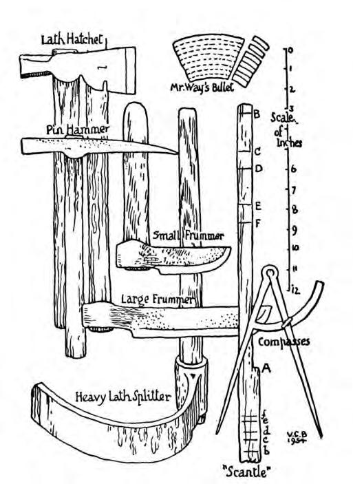
Following the introduction of the British Standard for roofing slates, BS 680, in 1942 (now replaced by BS EN 12326-1 Product Specification and BS EN 12326-2 Test methods) quarries limited the width of slates to not less than half their length. This was useful for centre-nailed, single size (tally) slating which relies on a defined minimum width for ‘normal’ head laps to be effective, but it is not appropriate for head-fixed slating which can safely accommodate narrower slates without leaking (Figure 9). Therefore, it is acceptable and preferable in head-fixed systems to include a proportion of narrower slates in an order.

12
Figure 7 Figure 8
Figure 9
Diagrams
Figure 7: In the past a slater’s kit included frumers for riving laths and pegs, and a break iron, sax and hammer for dressing and holing slates. This was usually wet weather work. Once the slates have been sorted into length (to the peg hole) the scantile stick and compass are used to mark up a guaging rod and the guages transferred to the rafters using a strong line. Laths are then trimmed to length where necessary with the hatched and nailed.
Figure 8: As the slates are fixed they can be redress if needs be with the sax and a dog or cutting iron driven into a rafter. The slater’s pin and hammer has a sharp spike for occasional reholding and a nail puller
Figure 9: The effectice width of head-fixed slates is greater than if they are centre-nailed. Following the introduction of BS 680 Roofing Slates in 1944 quarries adopted the ‘slate width not less than half the length’ limitation for all slates but this was in fact only necessary for centre-fixing. The consequent elimination of the narrower slates traditionally used in scantle slating has changed the appearance of roofs. For the conservation of old roofs the existing lengths and widths should be recorded and the narrow examples included in the specification and order to the quarry.

5 Work in general
5.1 Conservation approach
Conservation imposes additional requirements on building work over and above those required for new construction. Whilst the specific ways in which these requirements can be met will vary greatly from case to case, as will the reason for undertaking the work, the underlying principles advocated by the SPAB remain the same.
The Society believes above all that it is vital to maximise the retention of a building’s authentic fabric and minimise the disturbance to this to keep its integrity. This is achieved by carrying out essential work coupled with using compatible methods and materials.
Obtaining sound information about a building’s history, construction and condition before embarking on any major work is an important prerequisite. The level of recording entailed should be proportional to the significance of the building.
5.2 Selecting an architect or surveyor
An architect or building surveyor may be employed on larger, more complex projects, or projects where the re-slating is only part of the work. This should give the client protection if things go wrong, and a competitive tendering procedure should ensure that value for money is obtained. Professional advisors should be selected who have the right knowledge and experience to specify and inspect the work. For sources of names see Section 15.1.
5.3 Selecting a slater or slating company
It is most important to ask skilled and knowledgeable slaters to tender for the work. The key is to ensure parity of tendering. Then the lower price can be chosen. It is usually unwise to make a selection based on cost alone as an inexperienced slater may simply have underestimated the cost because they left out a step in the slating process. Problems can also arise if the main contractor is allowed to choose the slater because they too may be primarily concerned with cost.
The National Federation of Roofing Contractors
13
Table 3 National Vocational Qualifications in roofing
operates an accreditation scheme for heritage roofing companies which includes Patent, scantle and rag roofs.
There are national vocational qualifications (NVQ) for roof slating and tiling and construction site management (conservation) (Table 3)10. Older but highly skilled slaters may not have such qualifications but this should not disqualify them from consideration. These qualifications may be required by clients or be included in grant conditions.

A slater should be able to show roofs which they have successfully worked on and provide references. It is wise to view roofs which a company has repaired or reslated, preferably recently. Although an external view cannot reveal all the mistakes which may have been made, examples of good workmanship to look out for include:
- Evenly diminishing margins – no margins taller (longer) than ones lower in the slope
- Perpendicular joints roughly central on the slate below – any joints lying closely above each other are a serious fault
- Tidy mortar – neatly finished at the slates’ tails, verges and abutments
- Ridge tiles fitting closely onto the slating without large mortar beds
- In the roof space there should be no sign of leaks or dampness but these would only be visible if there is no underlay
- Similarly bedding mortar should not be visible from the underside of the roof but do not confuse this with torching.
The slater should be asked to provide a statement covering all the steps in reslating the roof including:
- Survey and recording – how the roof will be inspected before and during stripping to ensure historical details will be conserved and technical detailing will be replicated or if necessary improved. This may be subcontracted to a specialist surveyor and may have been carried out prior to tendering
- Specification review – advising on unsuitable or impractical aspects of the specification Method statement – a description of the process of organising the work
- The re-slating process - a description of the process of carrying out the work. This aspect is important because comparison between tenderers will highlight any step which has been omitted How they will deal with any faults or damage caused, for example, when dismantling scaffolding.
Quotations should state the total area of the slating work to be done so that differences can be checked and any aspects which are unknown until the roof is stripped should be clearly explained. It is also very important that all quotes are based on the correct gauging system. A price based mistakenly on slating at double-lap when threeand-a-half-pin is specified is going to seriously underestimate labour and materials.
5.4 Specifications
Any work on historic roofs should always be based on an understanding of the existing roof and how well it has performed. Ideally, a survey to record and photograph the constructional details should be carried out prior to writing the specification. This will involve some opening up of the roof. The survey should cover the general slating and eaves,
14
valley, verge, abutment, hip, ridge and dormer details and the slate sizes, their condition and gauging . It should also assess whether the roof has performed satisfactorily or if it has deteriorated prematurely because of some inherent defect. Care and experience are needed to differentiate between cause and effect. The survey could be carried out by a slating consultant, an experienced contractor, architect or surveyor.
Based on the survey findings the specification can be prepared. Where modifications are required to fulfil other objectives such as environmental performance, they should be based on sound information. In particular, care should be taken where insulation is introduced, especially on wetlaid scantle slating where a method for venting any moisture from the batten space must be provided.
This advice note includes roof details which vary across the region and should be replicated during repairs or re-slating. However, the location and geographical extent of their use is not necessarily known, so their application on a particular roof should be based on research, survey or other reliable information.
A written specification will allow the work to be detailed and the standards of materials and workmanship to be set out so that all slaters who are pricing the work can do so against the same document, and the prices can be judged on an equal basis. If the work includes more than slating, and is to be managed by a main contractor, a good specification will ensure that the method and standard of slating can be understood by all who tender and can be met by the main or slating sub-contractor. Under certain contracts a particular slating firm can be nominated.
The specification should cover the following issues:
Survey and recording if required
Policy on retention of historic details and materials Slate source, sizes range, thickness
Gauging:
for scantle this can be described as either threeand-a-half or four-and-a-half for roofing and two and half for cladding. To avoid confusion, the slate length divisor should be stated: 3.5 for roofing and 2.5 for cladding are typical for slating in thirds the gauge divisor is 3
for rag slating the head lap should be specified
Side lap – for scantle the requirement is to set perpendicular joints approximately central over the slate below; for rags and slating in thirds a minimum side lap can be stated
Battens or laths and fixings – sizes and materials Slate fixing method – nailed or peg-hung Slate fixings – nails or pegs, sizes and materials
Mortar, if required, including any preparation procedures and precautions to ensure satisfactory curing
Underlay
Insulation and means of ventilation
Details for eaves, verges, hips, valleys, dormers and ridges.
5.5 Listed building consent
For listed buildings, most changes to the construction details will require listed building consent from the local authority. Relevant changes will include the:
Reslating of a roof at the end of its life, where renewal would affect the building’s character
Removal and alteration of material and/or detail of archaeological or historic importance
Alteration of a detail such as ridges, valleys, hips, abutments verges or the style or size of dormer windows
Change from one slate type to any other slate or to clay or concrete tiles, imitation slates or sheet products
Use of slate of a different geological type, including another source quarry within a particular geological type
Change from riven laths to sawn battens or the reverse
Introduction of underlay with counter-battens which significantly raise the roof line
Change of slate fixing method, for example tophung to centre-nailed
Change in the overall range of slate lengths which would significantly affect the roof’s character
Use of new slates that have been prepared using nontraditional methods, such as sawn edges which have not been dressed to give a bevelled edge
Change of ridge or hip material, such as from one stone type to another or to reconstituted stone, concrete or clay ridges
Introduction of building service or ventilation details that would significantly alter the character of the building.
15
Local policy on these issues should be checked before making proposals for alterations. The policy is likely to cover three main options: Completely authentic reslating – an exact replication of the existing style and techniques; External appearance authentic but modern methods adopted, for example nailing rather than peg hanging; or Either of the other two but including modern innovations like insulation.
The third option is most likely to be driven by the building regulations.
5.6 Building regulations and other controls on roofing work
In addition to listed building consent, building regulation or, for many places of worship, faculty approval will be required for any increase or decrease to the weight of the roof covering. This will include a change from a slurried to a normal roof.
Where more than 25% of the roof area is to be replaced, the person intending to do the work has a legal obligation to contact the local authority building control department in relation to the upgrading of insulation to comply with the Part L of the building regulations - see Section 7.6. Places of worship are exempt. Historic England has published guidance on compliance with Part LBuilding Regulations and Historic Buildings11 . All bats and some birds and plants which live on or in roofs are protected. This will often limit the time of year when work can be done. The county wildlife trusts will be able to advise and other sources of information are given in Section 15.
6 Recording and assessment
6.1 Recording and condition surveys
Any work on historic roofs should always be based on an understanding of the existing roof and how well it has performed. Each surviving example is likely to contain valuable information about historic craft techniques. It is important that the recording of such information is undertaken before the slating is stripped and the results used to develop a specification for the re-slating. This will minimise the possibility of delays and errors in the ordering of any new slates, and importantly will give the owner of the building more certainty over the final cost. If no survey is done, assumptions about the quantities of slates needed will have to be made at the time of specifying the work in order to obtain prices. For scantle slating where there is flexibility on lengths, potential shortages of smaller sizes can be overcome by ordering extra longer slates which can be used on shorter courses. For rags, however, small quantities of specific lengths and widths will often be needed and will not be known until either a survey has been carried out or the roof has been stripped. The potential delay in obtaining them should be built into the contract programme. Where defects occur, they are frequently down to poor maintenance, unsuitable alterations or inadequately sized members, and result in decay or distortion of the roof.
6.2 Structural deterioration, rafter settlement and deflection
Most historic roofs will have moved during their life. Commonly, because of inadequate restraint by couples etc, the eaves will have spread, pushing out the walls, and the ridge will have settled. Rafters may also have settled along their length or adjacent to walls. These features give roofs much of their character and should not be rectified unless there is a clear structural reason to do so. Every effort should be made to conserve the structure that supports the roof covering. It is frequently one of the least altered parts of an old building and may provide valuable clues about its history. These range from smoke-blackened timbers where a medieval open hall preceded
16
a chimney, to remnants of early decoration and evidence of smoke bays or louvres. Many old roof structures also constitute fine examples of craftsmanship, jointing is often exemplary and features such as crown posts, moulded beams and traceried early spandrels may be found. A technical assessment will often indicate that stabilisation of the structure is all that is necessary. However, deflection or settlement of the structure may have created undulations in the roof slope which are impossible to slate without gaps, especially for larger slates such as rags. In this case it is acceptable (and essential) to ease the undulations by packing the rafters or similar. Where settlement is less severe, gaps under the slates can be reduced by using narrow slates which will fit more tightly across the undulations.
6.3 Nail failure
Rusting of iron nails used to fix laths or slates is the main cause of slates becoming detached from the roof. Loss of slates individually indicates that it is the slate nails which are failing. This will be a gradual process and they can be refixed for a time. If lath nails fail several slates in a course will slip (Figure 10).
6.4 Lath failure
Lath failure is indicated by courses of dropped slates or undulations in the roof plane. If the failure is extensive then the roof will need to be reslated. Laths may be unable to carry the slates’ weight if they have been weakened by rot or insect attack, or if the slating has been grouted and slurried. Repeated slurrying increases the load on the laths and when it becomes too heavy for the lath nails large cracks called riffles form (Figure 11). To overcome the slippage barbed wire was laid over the ridge and turned under the eaves slates or nailed into the rafters and covered with a mortar fillet. This is only a temporary solution. Slurrying and grouting reduce the roofs ability to breath resulting in rotting of the laths and structural timber.


6.5 Slate failure
Slates currently sourced from Cornwall and Devon are durable and will only reach the end of their lives after many, commonly hundreds, of years. Typically, the process of slate ageing is a general
softening in the overlapping parts of the slates. Less durable slates may fail for three main reasons: the presence of deleterious minerals; inherent weakness or because of mechanical stress (see box page 11).
Figure 10
Figure 11
17
Figure 12 Diagrams
Figure 10:Where whole courses of slates are seen to have slipped the cause is usually failed lath nails (Godolphin)

Figure 11: Grouting and slurrying roofs substantially increases the loading on the lath nails. When they fail and large areas of slates slip, cracks known as riffles appear across the roof (Penzance)
Figure 12: ‘Now the pins are put firmly into the holes and the slates piled so that they will stand without toppling: so many with pins lapping one end and so many the other, and still in sets of equal length.’ Boyle, VC, Scantle Roofs, in Devon and Cornwall Notes and Queries 26, pp10-15
7 Repairs and re-slating
7.1 Alteration of details
It is normally assumed that a like-for-like repair or re-slating – same slates, same gauging, same bedding, if originally used, etc – will perform satisfactorily in the future. However, the implications of the increasing incidence of deluge rain and more severe storm force winds consequent on climate change should be considered in deciding on the gauging and the fixing method. An improved specification can usually be adopted without impact on the appearance of the roof but specialist advice may be needed so that all the implications of changes are taken into account and an integrated solution achieved. Simply applying the recommendations for each element in isolation is unlikely to be successful.
7.2 Structural repairs
All roof work should be carried out from a safe means of access that does not damage the roof. Scaffolds should be designed to carry the weight of stacked slates and to be wide enough to
allow sorting and redressing. The NFRC provides guidance publications - Sheet A: Fall Protection and Prevention for Working on Roofs, Sheet E: Slater’s Heel and Sheet M: Working at Height.
It is better to repair rather than replace roof timbers. Consult a structural engineer where necessary and leave only minor repairs to roofers. Whilst conventional carpentry techniques alone will frequently be suitable, strengthening using steel may be justified where it allows more timber to be retained than would otherwise be possible. Use resins and consolidants only with great care.
Where active decay exists, the first priority is to eliminate causes of dampness and promote drying. Chemical treatments are frequently unnecessary and should only be used judiciously where justified as a secondary measure, for example, when it is difficult to reduce moisture levels sufficiently. Degraded surface material should not be removed (defrassed) without good reason. Serious mutilation can result.
Keeping roof spaces clear of rubbish and debris discourages decay. Timbers may be vacuumed or brushed down – though take care not to remove
18
any medieval smoke blackening or evidence of early decoration that is of archaeological value. For further advice on work to roof structures see the SPAB Technical Pamphlet 12.
7.3 Slates
Although slate roofs which are reaching the end of their life can be kept weather-tight for many years by regular maintenance, eventually they will have to be stripped and reslated, typically when 5-10% of the slates have slipped or been lost. The decision to reslate is often precipitated by the repeated cost of scaffolding for repairs.
When carrying out repairs the primary aim should be to retain the maximum amount of historic fabric without compromising the effectiveness of the roof. The existing slates should be reused if they are still sound or if they are damaged or softened, they can be dressed down to remove any defective areas.
Only slates from the local sources can produce an authentic appearance. Slates from other locations should not be used unless there is no local source. For extensive re-slating, new slates should be used to make up any shortfall. This may be local authority policy and a condition for any grant supported works. Claims of unavailability or long delivery times should always be checked with the quarries. It may be worth delaying the project for a few months until the right slates can be produced, since the life of a well-slated roof is likely to be in excess of 100 years. Only where it is impossible to obtain suitable new slates should the use of reclaimed slates be considered. These will not last as long as new and their use inevitably means some other building will have lost its historic roof. Often they are sourced from several other roofs so their remaining life will be mixed. They should be checked for softening and damage especially around the fixing hole. Affected areas can be dressed off but this may result in a shortage of the longer sizes with a consequent change in the roof’s appearance. It is better for appearance and durability reasons to consolidate old slates on to one or more slopes and to use the new ones on others.
When stripping and reslating scantle roofs any shortfall should be made up with new slates supplied in a mix as they arise in the quarry but
with appropriate scantle widths. Normally the new and old slates should be fixed on separate slopes. When the existing slates are consolidated and sorted into lengths the number of courses of each length can be calculated.
Rag slates are not always immediately available and have to be specially ordered. Suitable block for such large slates may not be readily available so the order should be discussed with the quarry as early as possible.
The quarries are always willing to make special slates but they will need a detailed specification of what is required and almost always time to organise production of any special slates. An order might include sizes, quantities, colour, texture, and most importantly the date work is to commence and, for large projects. The scheduling for each stage. It is always wise to discuss the order and work programme well in advance. If a roof is to be stripped and re-slated, there will inevitably be uncertainty about the quantities of slates needed until the numbers of reusable slates are known. Experienced slaters or independent consultants can advise on this before stripping commences.
The individuality of rag and scantle roofs derives from the mix of slate sizes. Historically, no attempt was made to supply a specific mix of sizes and this policy should be respected for most re-roofing work. How the slates were fixed and the detailing was mainly a response to the weather. In sheltered areas, especially in Devon, scantles are laid without mortar bedding (dry-laid) whereas in exposed parts of Cornwall tail-bedding with mortar (wet laying) is used. The use of large (rag) slates at the eaves or verges of scantle roofs is also a precaution against wind damage. Similarly large slates at the eaves (mounters) span the space between a rafter footed onto the inside face of a wall without the need for a sprocket.
Roofing slates produced today may be thicker than formerly. This can cause them to lie on the roof at a lower angle than thinner ones and the shortest slates near the ridge might become unacceptably flat. This problem can be alleviated by using a range of sizes slightly larger than traditional - say one size larger for the first course(s) and two sizes larger at the top of the roof. This should be discussed with the conservation officer.
19
7.4
Slate repairs
The thickness and size of missing or damaged slates must be determined and matched and this will probably involve opening up the slating. If the slates are pegged it may be possible to swing adjacent slates aside and hang the new slate. If the slates are nailed or if the slating has to be opened for another reason then a triangle of slates should be removed so that each one can be accessed for refixing and the last one can be slid up and pegged by moving adjacent slates. Inevitably any bedding or torching will be damaged and this should be renewed.
Refixing slates by simply bedding them in mortar should be avoided but is sometimes necessary as an emergency and purely temporary measure. Cement mortar should not be used as any water getting behind it cannot evaporate through it and more damage will ensue. Lime mortar of the torching type placed high on the underlying slates is preferable. However, slates fixed in this way will not be fully secure but a small dab of bedding mortar under the tail will prevent them lifting in the wind.
Roofs in the south-west are often inadvisably repaired by grouting and slurrying with mortar; covering the slates with hessian and bitumen (Turnerising); or spraying foam on the slates’ undersides. These techniques make it expensive or impossible to re-use the slates and reduce the ventilation through the roof, increasing the risk of rot or insect attack. This will be aggravated where insulation is installed in the roof. Grouting or slurrying leads to structural deterioration and will eventually cost far more than if the roof had been re-slated instead. Although slurried roofs are a distinctive feature of the region they are no more than a temporary repair – a last resort for a roof which has failed - and should not be replicated when the roof is reslated.
7.5 Fixings
Lath nails should be no less durable than galvanised or sheradised and sized to suit the laths or battens. Stainless steel nails are sometimes specified for lath or batten fixing especially in marine situations but not all types are equally durable. There have been failures associated with AISI grade 304 slate hooks in coastal areas and
current advice is to avoid this grade for roofs and only use 316. However, standards and grades of stainless steel are changing and the NFRC technical bulletin 11 should be consulted for full details13
For 50 x 25 mm softwood battens a 3.35 mm shank diameter is recommended in BS 5534. Shank length and diameter should be chosen to provide adequate pull-out resistance for the building’s situation, height etc. BS 5534 provides further guidance. Smaller nails will be needed for fixing thin riven laths to avoid splitting them or the laths can be pre-drilled. Alternatively cleats (cooper’s hooks) can be used.
The traditional fixings for wet or dry scantle or rag slates were soft or hardwood pegs. They were a roughly square section and whittled to a slight taper and forced into the hole until almost flush with the slate’s surface. The slates were then stacked before carrying up to the roof14 (Figure 12).
On a pegged roof where the underside of the roof is to be visible, wooden pegs should be used and will be prevented from twisting or falling out by the addition of a small dab of mortar (pin pointing) or by torching. Otherwise, nails can be used in the same way as pegs.
Where wood or metal pegs are used over underlay they must not be so long as to risk puncturing it especially close to the rafters. Counter battens may be necessary to ensure they are well away from the underlay but these can create other problems at abutments etc. For slate nailing, copper or, in salt water exposed situations bronze nails are the most durable option. Aluminium nails are also suitable but should be avoided where they might be in contact with lime mortar. Ring-shanked nails should not be used as it will be impossible to remove the slates in the future for reuse without breaking them. Stainless steel nails are too smooth to provide adequate pull-out resistance in most situations. Small nails - 2.65 mm shank diameterare satisfactory for scantle slates but for larger sizes such as rags the BS 5534 recommended 3.35 mm shank diameter is appropriate. Nailing rag slates into old hardwood rafters may require pre-drilling to avoid breaking the slates. Hook fixing is not traditional and should not be used on old roofs.
13.
20
Lath gauging
(a) For a given slate length the lath gauging is consistent for each course (Addislade).


(b) When a shorter length is introduced the gauge is reduced. This is know as the twist. Failure to do so means the head lap will be too small and the margin too long.
(c) Narrower laths may be needed for the smaller slates in the upper courses to provide space for the pegs.
14.
If a hip has unequal pitches on either side and the slating is mitred the lath gauging must be carefully worked out so that the margins match without compromising the head laps.
15
The eaves slating must be tilted to ensure the slates lie tight onto each other without gaps where the wind could lift them. This was often done by setting the rafter foot back from the wall face or by extending the wallplate. If the rafters oversail the wall a tilting fillet is placed on the rafter foot or, if there is a fascia, by raising it to lift the eaves slates.

 Figure
Figure 13c
Figure 14
Figure
Figure
Figure 13c
Figure 14
21
16
13a
13b
Figure 15
Large mounter slates are often used at the eaves to resist the wind and to throw water away from the wall where there is no gutter (St Erth).
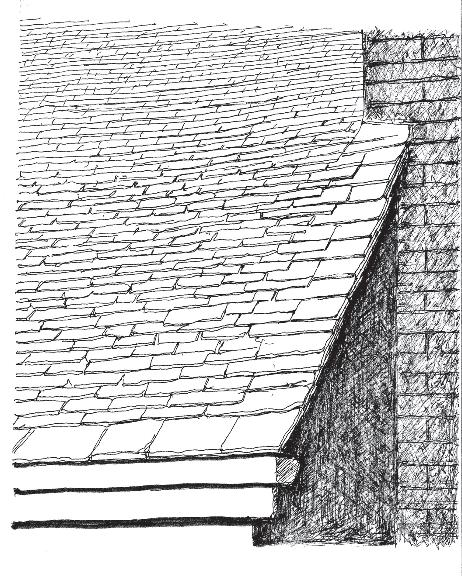
17
If the slating is wet-laid, the mortar bedding is either reduced in width or omitted between the under eaves and the eaves course to allow any condensation in the slating to drain away (St Ives).
7.6 Laths, battens and sarking boards
Historically, riven laths were used for all types of slating except rag slating and are satisfactory for peg hanging all the slating types in this Advice Note (Figure 13(a)). Made from a variety of woods including oak and sweet chestnut they are typically 25 mm by at least 6 mm thick and in length 900 to 1800 mm.
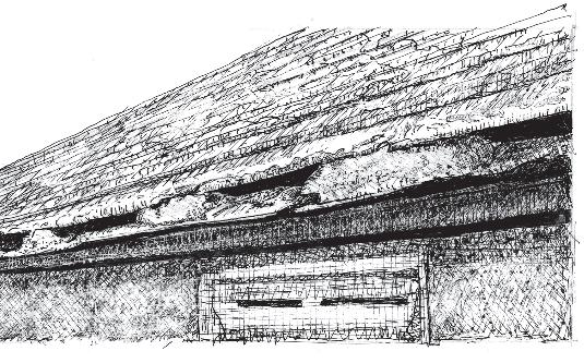
They are available from specialist suppliers. Being riven they are not straight and impart undulations to the slating which gives a more lively and less mechanical appearance to the roof. Also they are less prone to beetle attack than sawn battens. For small peg-fixed slates, battens need to be narrower near the ridge to allow space to insert the pegs between them as the gauge reduces (Figure 13(c)). Formal guidance for slating, such as BS 5534 recommends thicker battens of 50 x 25 mm, which are regarded as providing a safe platform for slaters to work on. If riven laths are used a risk assessment may be needed to justify their use. A slater’s heels are a suitable option. Changing from riven laths to thicker sawn battens will raise the roof level and may lead to problems at abutments and verges.
Listed building consent will be required. Slating was commonly laid over sarking boards and these should be retained wherever possible. They fulfil most of the functions of underlay in keeping
out draughts, powdery snow and dust, reducing the wind uplift force acting on slates and acting as a moisture buffer. Under correctly laid slating there is no need to include an underlay over boarding and its addition will reduce the ventilation of moisture from the roof space. Even the addition of a vapour permeable membrane will have a lower rate of ventilation of moisture than no membrane at all. To ensure ventilation through the boarding they can be laid with penny gaps. If an underlay is needed to provide temporary weather protection it can be removed as slating progresses.
7.7 Insulation and ventilation
Part L of the building regulations requires the addition of roof insulation for most substantial repairs, including partial re-slating. This can increase the condensation risk in the roof structure unless precautions are taken. BS 5250 The Control of Condensation in Buildings provides advice on how to minimise the risk. Vernacular roofs were built with inherently good ventilation which prevented moisture build-up and condensation in all but the most adverse conditions. This is one of the main reasons they survive for so long. Underlays were not included in old roofs and draught-proofing was provided by lime mortar torching. This would temporarily absorb moisture and release it when the weather was more
Figure
22
16 Figure 17
favourable.
It will be difficult for many older buildings to achieve statutory target U-values without compromising their appearance and it may be impossible. Part L allows for exemptions and special consideration for historic buildings to enable building control officers to take a sensible view in order to conserve the appearance and character of the building and not introduce technical risks. Historic England has published guidance on complying with Part L15 .
To prevent condensation problems, the first step should always be to reduce the amount of moisture reaching the roof. This has two aspects: elimination at source, especially for bathrooms and kitchens, and the installation of a vapour control layer at the top floor ceiling or at the rafters. To be effective a vapour control layer must be sealed at all joints, perimeters and penetrations but this can be very difficult as a retro fit.
Having minimised the moisture reaching the roof space it is important to ventilate any which does. This can be done with eaves, high-level or ridge ventilators or with vapour permeable membranes. Ventilation product manufacturers provide guidance on the amount of ventilation required and the levels their products achieve under ideal conditions. Where Agreement Certificates are available they should always be checked for the limitations applying to products. For example, many vapour permeable membranes will only achieve adequate performance provided a vapour control layer is installed below the roof. It is preferable to place insulation at ceiling level rather than in the rafter depth because it is easier to provide ventilation through the roof space via eaves to eaves, eaves to ridge or through gable walls. However, this may be undesirable where there is an historic ceiling or lining.
Providing ventilation for insulation placed in or above the rafters can involve raising the slating on counter-battens leading to problems of detailing and changes to the building’s appearance at eaves, abutments, below copings and at verges. Secret gutters at abutments can be used to avoid the need to cut into the wall to reposition flashings or a string course. But they will need regular maintenance to avoid blocking by leaves or other debris.
Where there is natural ventilation, at the eaves, for example, it is important that it should not be impaired by the insulation. Roofing specialists are the best sources of advice on this rather than insulation installers who probably know little about roof construction.
Wet-laid scantle slating is a sealed system so if there is any sort of membrane or underlay installed or a ceiling is fixed to the rafters it is vital that the batten space is ventilated. This will usually necessitate eaves ventilators and high level vent(s) in the roof slope or at the ridge.
7.8 Mortar
The use of mortar has a long history in roofing. It has been applied to improve the wind resistance of slates and prevent draughts, as well as for bedding slates, ridges and hips, pointing verges and forming abutment fillets. Mortar is important in scantle slating because the slates are short and the gauging small, so their heads tend to be lifted away from the laths, especially in the upper courses. This makes them susceptible to wind-lift and this is overcome by bedding the tails of the slates, tipping the heads onto the lath.
Lime rather than cement was the binder for most roofing mortars before the early 20th century and is being used increasingly for this purpose again today. Roofs move under the influence of wind and temperature so it is essential to use a flexible bedding mortar to avoid cracking. Strong cement mortars (1:3 or 1:4 cement:aggregate) should be avoided because of their inherent rigidity and impermeability. They result in cracking and loss of adhesion. Old roofing slates (sometimes irreplaceable) are likely to be damaged beyond repair when later rebedding or relaying is necessary if they have previously been laid in cement mortar.
The recent resurgence of hydraulic limes in Britain, and their development and increased use in both conservation and new-build work, now makes it possible to use lime mortars which are durable in exposed conditions. Although historically mortars for bedding scantle slates may have been nonhydraulic or only weakly hydraulic, hydraulic lime mortars are more commonly specified today to give a speedier set and greater durability. There is a wide variation of mixes using different
23
strengths of hydraulic lime and varying proportions of aggregate. These need to be selected to suit local weather and building exposure conditions.
Due to the level of exposure to wind, rain and sun to which roofs are naturally subject, various levels of movement of slates are inevitable. The softer, richer and more flexible mortars (possibly also containing hair) are likely to cope best with movement, but the tougher and harder mortars with extreme exposure conditions. The type of lime and form in which it is used will also affect adhesion. Hydraulic lime is less ‘sticky’ than nonhydraulic lime. Lime may be included in the form of quicklime, lime putty or bagged dry hydrate. Generally, working from the former to the latter of the three, the extent of adhesion and workability will be in descending order. Sources of information on mortar are given in Section 14.
Table 4 indicates typical lime-based mixes that can be used for work on old slate roofs in south-west England. It is not exhaustive. For example, hot lime is being increasingly used for roofing and should be considered where investigation of the roof indicates it was originally used successfully. The aggregate should be a clean and well graded sharp sand with angular particles, which will bind well with the lime and leave minimal voids. The thickness of mortar beds for slating should be no more than 5 mm but may be due to the unevenness of some slate surfaces. Where thicker beds are unavoidable, it is important to keep the aggregate size sufficiently large to prevent cracking. The size of the largest aggregate particles should normally be about one-third of the mortar bed thickness.
The mortar should be mixed in a pan or drum mixer for a minimum of 30 minutes. Only mix sufficient quantities for immediate use unless trials have been carried out to show that they may safely be knocked up without the need to add further water. Non-hydraulic lime that is kept damp can usually be left overnight, as sometimes can certain weaker hydraulic limes. This is inadvisable, however, with NHL 5 and some NHL 3.5 limes. The principle of mixing is to achieve a good dispersion of lime and other constituents with the dry sand before any water is added. Once the dry mix is fully dispersed water should be added slowly, allowing time for this to become fully mixed
before deciding on the amount needed to achieve good workability. Bear in mind that too much water will decrease the mortar strength by holding the grains apart thus leaving an open structure when dry.
Protection of all new lime-work against the weather is almost always required. If possible, avoid working in the winter months when there is a risk of frost, because freezing and expansion of water can damage uncarbonated areas. To prevent this, layers of hessian or another insulating material must cover the roof (leaving air gaps). The use of anti-freezing agents in mortars is not recommended.
Rapid drying of the mortar by the wind or sun will produce a light-coloured surface with an increase in the deposition of lime binder and risk of cracking and powdering; when this occurs the work will have to be redone. All lime mortars must harden in the presence of moisture. Covering with polythene over damp hessian will provide a microclimate that encourages carbonation. A fine mist spray applied daily for a minimum of four weeks where this is practical is also beneficial.
24
Notes
(i) NHL denotes a natural hydraulic lime. Natural hydraulic limes are classified under BS EN 459: Part 1: 2015 Building Lime17 as NHL 2, NHL 3.5 and NHL 5 in order of increasing strength. The classes refer to the compressive strength in megapascals of a 1:3 lime:sand mix by mass (approxomiately 1:1 by volume) after 28 days. Users should be aware, however, that the strength continues to grow considerably over the first couple of years so the final result may be a much stronger mortar. It is also important to note that the NHL classification accommodates a wide range of strength within each class.
(ii) Cement:lime:aggregate mortars are often used for work on the roofs of old buildings but great care must be taken to control the mix proportions on site to avoid the problems associated with excessive strength.

(iii) Pre-mixed lime mortars are available that minimize material handling and quality control problems on site. It is advisable to clarify with the manufacturer, though, whether any additives are present, as some will be unsuitable for conservation work.
(iv) The inclusion of well graded crushed limestone for, or as part, of the aggregate will aid moisture entrainment and carbonation, and enhance frost resistance.
(v) Where lime mortar is applied in thicknesses greater than 15 mm, the same principles should be followed as with external lime render, ie use more than one coat, incorporate hair in the first of these and ensure the aggregate is sufficiently coarse.
8
Specfications and detailing
8.1 Slating specifications
Specifications should include the materials to be used, methods to be applied and the detailing of local areas such as eaves hips and valleys etc. All slating should be specified and constructed to provide adequate head, side and shoulder laps to resist driving rain and be fixed to resist wind uplift. The different slating systems achieve these objectives in different ways. These are explained below.
Slates should be laid without gaps underneath them. For single sized (tally) slates this is done by sorting them into sets of equal thickness and laying them with the thickest at the eaves grading down to the thinnest at the ridge. This is not possible for random sized slates because they have to be positioned on the slope where their length dictates. Therefore they must be selected as they are laid to ensure adjacent slates are equally thick. For wet-laid scantles the mortar bedding takes up any variation.
All random slating should be set out to provide the required head lap by using one of the gauging systems described in sections 3, 5.4 and 9-11. There is little reason for variation in the general slating. The gauging rules are normally applied consistently to all slopes unless there are different pitches across an intersection such as a hip or a close mitred valley. In this case the margins are sometimes coursed across the pitch change. To do this the gauging is worked out on the lowest pitch and then the lines of the tails are struck across to the steep side and slates long enough to provide the lap over four courses are selected for each course and the laths fixed to suit (Figure 14). This can also be worked out by calculation or with a scale drawing.
8.2 Eaves
The slating should overhang at the eaves to discharge water into the gutter where there is one or well away from the wall if not. A tilt (springing) must be provided to lift the tail of the under eaves slates to ensure the subsequent courses lie tightly onto each (Figure 15). This is done either by fixing a tilting fillet, by raising a fascia board or, if the rafter
is set back on the wallhead, by packing up the masonry. Eaves slates are vulnerable to wind uplift and in exposed locations may need additional nailing near their tails. If rafters extend beyond the wall, the slating can be protected by soffit boards. A variation seen across all three counties is to form the eaves with one or two courses of rag slates, known as mounters or prickers, nailed to rafters. These are more resistant to wind lift and, where there is no gutter, they discharge water well beyond the wall without the need to use a sprocket to carry smaller slates (Figure 16) Eaves are usually formed with one course of undereaves slates but sometimes with two. If wetlaid, the mortar bedding is either reduced in width or omitted between the under eaves and the eaves course (Figure 17).
8.3 Verges
Verge (windspur) slating is finished with a slight overhang to the gable wall or slate cladding and a mortar fillet under the slates; over a barge board or an external rafter; or abutting a coping (Figures 18). The slating is often raised slightly to direct water back onto the roof slope.
Verges are very susceptible to wind damage. Localised techniques to overcome this include using large (rag) slates spanning two or three courses of scantle slates (Figure 17), bedding bricks or stones onto the slates (Figure 19) or fixing a verge board over the slates18 .
Where there are external rafters they, and any exposed purlin ends, are often protected with slates known in some areas as scrips (Figure 20) and are sometimes decoratively shaped (Figure 20). They are either butted end to end with the nails exposed or covered with a mortar fillet, or they are overlapped by about one-third to protect the nails.
Where two or three courses of scantle slates are laid up to a rag slate verge, they are selected to have a combined thickness equal to the rag slate.
26
Figure 18
Verge or windspur slating can be finished in a variety of ways:

(a) with a slight overhang to the gable wall or cladding and a mortar fillet under the slates (Marazion); (b and c) over a barge board or an external rafter (Carnglaze & Dunster) or (d) abutting a coping (Gwithian).
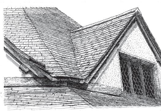

Figure 19
In wind-exposed areas verge slates are often held down with coping stones or bricks bedded in mortar (St Ives)
Figure 18d
 Figure 18b
Figure 18c
Figure 18b
Figure 18c
27 Figure 18a
Figure 20
Where there are external rafters they, and any exposed purlin ends, are often protected with slates known as scrips. These are either:


(a) butted up with the nails exposed (Bridestow) and Figure 23 or (b) overlapped to cover them (near Dartmouth) (c) Scrips are often used as a decorative detail (Near Marazion)
 Figure
 20a
Figure
Figure
Figure 20a
Figure
28
20c Figure 19
20b
8.4 Abutments
The junction between the slating and abutting walls and chimneys can be difficult to make water tight. Historically, they did not include soakers and relied on mortar fillets (flaunches) (Figure 21(a)) or slates bedded in mortar and nailed onto the wall to prevent water penetration (Figure 21(b)). These were often protected by droppers (feathers) (Figures 21(c)) and the slating might be tilted slightly by raising the last rafter or packing the laths to direct water away from the junction (Figure 21(d)). It is possible to conserve the appearance of abutments but to include concealed lead soakers. These and cover flashings became common once lead became economical, but the latter can be visually intrusive and mortar flaunchings are preferred. Nonetheless the flaunchings can be problematical as they often crack and leak. To reduce this pieces of slate were bedded into the mortar. When renewing fillets the risk of cracking can be reduced by avoiding hard mortar, separating it from the slating and incorporating stainless steel mesh screwed to the masonry joints (Figure 22).
8.5 Ridges
The earliest ridges were finished by carrying the windward side slates above the opposite slope or with wrestlers (Figure 23(a)). During the 19th century Patent slate ridges and hips were made at Delabole quarry and these are occasionally still in place (Figure 23(b)). New pieces to replace any broken parts can be manufactured to order. More commonly ridges are covered with clay ridge tiles or crests (creces) which are sometimes decorative (Figure 23(c)). They should be back-bedded in mortar which should not show at the long edges as far as possible and not be pointed.
Where dormer ridges run into the main slating they are either swept up into the main slope or the junction is weathered with a lead saddle (Figure 24).
8.6 Hips
Before lead and ridge tiles became commonly available hip slates were mitred and bedded with clay or mortar, sometimes with a mortar roll (Figure 25(a)). Some unusual techniques have been used to try to protect the open joint, for example, by
extending the slates beyond the arris on one side and butting the opposite slate tight up under it. Elsewhere hips were in effect swept so that the joint was covered and lapped (Figure 25(b)). Today the mitre is normally weathered with lead soakers and if the adjacent slopes have unequal pitches it is good practice to adjust the gauging and hence the margins so that they course across the hip (Figure 14). Cut slates on mitred hips are vulnerable to wind damage so to reduce this risk wider slates are selected for the raking cut (Figure 25(c)). An alternative wind-resistant option is to use clay or slate ridge tiles or cast in situ concrete but this can spoil the slates for re-use in the future (Figure 25(d)).
8.7 Valleys
The difficulty of making a watertight valley has been tackled with ingenuity, especially before the ready availability of lead for soakers. Various methods relying on slates laid up the centre of the valley, sometimes bedded in clay or mortar, have been used in the past and these add to the character of the building. There is no reason why they cannot be replicated and if their effectiveness is in doubt lead soakers can be unobtrusively interleaved in each course. On an old roof this is far preferable to an open lead valley. Examples include swept, sometimes with a very wide sweep, and collar and tie (Figure 26(a-c)).
There are many subtleties in the way valleys are constructed. Some, for example, slightly raise the slating at the valley to turn water away from the junction. Information and videos of valley construction can be seen at www.stoneroof.org.uk/ historic/Historic_Roofs/Introduction.html
29
Figure 21
Historically, abutments did not include soakers and relied on a variety of techniques to prevent leaks. The junction with a wall or coping could be protected with:
(a) a mortar fillet but these are prone to crack (St Erth)
(b) sealing slates to the wall with mortar and nailing in place (Bridestow)
(c) slates laid in the wall (crow steps) to provide an overhang to throw water away from the abutment (Marazion)

(d) tilting the slating away from the junction by raising the last rafter (St Erth).


Figure 22
To help prevent fillets cracking slates, known as listings in some regions, were bedded into the mortar. A modern alternative is to reinforce the mortar withstainless steel expanded metal and to separate it from the slating with a temporary board. This allows the wall and roof to move independently without stressing the flaunch.
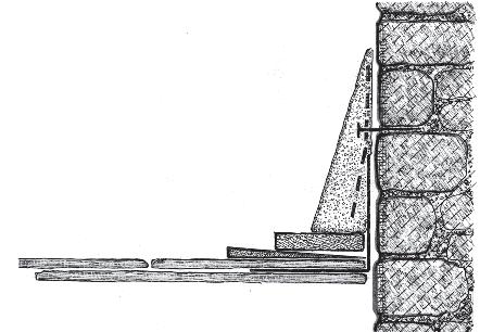
Figure 21b
Figure 22
Figure 21a
Figure 21c
Figure 21d
30
Figure 23 Ridges

(a) Before the use of clay ridge tiles became common the ridge slating was usually closed with overlapping or interlocked slates. (wrestlers). The overlap would face away from the prevailing wind (Tintagel).

(b) Ridges could also be formed with patented wing and roll slates screwed to the rafters. These were made in two or three parts: A combined wing and roll or two wings and a separate roll.
(c) Eventually clay ridge tiles became almost ubiquitous. Often with a decorative crest (Trevarno).
Figure 24
The ridge of a dormer can be formed with a lead saddle or swept up into the main slating


Manufactured and sold by Mr J Carter Agent to the Patentee. Old Delabole Slate Quaries, Near Camelford, Cornwall.
Figure 23b
The ridges consist of three pieces of slate, viz. two sides and a roll as shown. The roll is prefectly round, presenting a bold appearance, and being made in the strongest way of the slate, is reckoned superior to any other. They may be had in separate pieces, or united in one solid piece, in length from 4 to 6 feet, the roll of each length projecting 1¼ inch over the sides of the adjoining length, and to any given angle. When placed on the roof in separate pieces, the sides can be nailed or screwed to the batten, and the roll bedded upon them in blue putty, and if found necessary a screw put through the ridge piece. When united they need only to be placed on the roof like a common tile. Parties if they wish it, may buy them in separate pieces and unite them themselves after the manner of the Patentee, with metal angular plates screwed to the roll and the sides underneath as shown.
 Figure 23c
Figure 24
Davey’s Patent Slate Ridges and Hips.
Figure 23c
Figure 24
Davey’s Patent Slate Ridges and Hips.
31
Figure 23a
Figure 25
Like ridges, hips only carry a modest amount of rain which naturally drains away from them so sealing the junction is less onerous than for valleys. They are, however, very susceptible to wind and need to be securely fixed:
(a) Although today they would normally be soakered, historically the slates were simply bedded in clay, mortar or a mastic or putty (St Mabyn)


(b) The vulnerable hip junction was sometimes protected by forming a sort of roll hip with slates in alternate courses laid across the joint and cut to align with the slate courses


(c) To improve the wind resistance the hip was often made with larger slates selected from the stock (Tintagel)Covering the hip with a tile or with slates like Davey’s Patent ridge allows smaller slates to be used
(d) In many areas the most commonly seen hip is concrete cast in situ but these have only come into use since cement became generally available (St Ives).
Figure 25c
Figure 25b
Figure 25d
32
Figure 25a
8.8 Dormers and rooflights
Within the region the position of dormer windows can be below, through or above the eaves or wholly within the roof slope (Figures 27(a-c)). Most commonly the cheeks are slate clad or covered with single slate panels with soakers at the junction with the roof slope (Figure 27(b)). It is not uncommon for them to be glazed (Figure 27(c)). Before the general adoption of lead saddles, ridges were swept up into the main slating.
Rooflights are an alternative to dormers and being much cheaper to install are common on industrial, farm and similar buildings. They are an important feature of many farm buildings but are usually quite small. In there simplest forms a sheet of glass is substituted for a slate or is inserted into the slope and the slating overlayed (Figure 28(a)). Where the extra cost was acceptable cast iron lights are used (Figure 28(b)). The scale of the rooflights in relation to the roof slope is an important consideration in roof renewal.
8.9 Torching
Torching stabilises the slate heads and pegs; closes the roof against draughts and powdery snow blowing into the roof, and conserves the historic appearance of the roof from the inside. It should never be omitted from any repair work unless underlay is installed. It is applied to the underside of the slates and may be a single, thrown coat of lime mortar which has been left rough and not troweled. On small, scantle slates it may be applied just to the top of the slates or cover their backs completely between the laths and, if a second coat is applied, this may be troweled or floated as the background of laths and pegs will be sufficiently covered to allow this. It is very important that torching is not forced too far down between the slates to avoid drawing water to the laths and rafters.
Both domestic and agricultural buildings are found with two-coat work, which indicates its importance. It became more common in houses when roof spaces were adapted for home workshops. In shippons or cow houses it was used because cattle will not tolerate drips.
8.10 Farm buildings
These tend to remain unaltered for long periods and are often the best source of information on early roof structures and slating techniques. Their detailing is less elaborate than domestic buildings and this should be respected in repairs. Verges and eaves often have little overhang and gutters are seldom included. Lighting for storage areas or livestock was not important so it was often provided by replacing a few slates with glass or by installing small cast iron rooflights rather than dormer windows (Figure 28). Good ventilation is important for livestock but this was usually provided by openings in walls rather than roofs or by raising a few ridge tiles.
9 Scantle slating
9.1 The scantle process
This involves four main steps: making a scantle stick; preparing the slates; setting out (gauging) the roof; and fixing the slates. If lime mortar is to be used, this is made well in advance of the slating work - historically by as much as three monthswhen the building foundations were being dug. A scantle stick is prepared by marking on a set of slate lengths and then a set of lath gauges using the appropriate divisor (Figure 3). This will be three for slating in thirds; three-and-a-half for wet or dry-laid scantle roofs and usually two-and-a-half for cladding. It is possible, although not necessarily any more convenient, to work out the gauging by calculation.
9.2 Preparation
New, and if appropriate reclaimed, slates are first holed about 25 mm (one inch) from the top and sorted into sets of equal length measured from the hole to the tail. The slates were traditionally numbered rather than using their lengths in inches for example, 1 equals 152 mm (six inches) long; 2 equals 178 mm (seven inches) etc, up to 9 equals 356 mm (fourteen inches). But there are other systems and some are numbered in reverse, that is, the lowest number is the longest slate. The total width is then measured or estimated for each length and these values are divided by the roof’s
33
Figure 26b
Figure 26a
Figure 27a
Figure 26c
Figure 26 The difficulty of making a watertight valley has been tackled with ingenuity, especially before the ready availability of lead for soakers. Various methods relying on slates laid up the centre of the valley sometimes bedded in clay or mortar have been used in the past and these add to the character of the building. Examples of traditional valleys include:

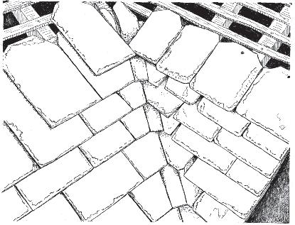

(a) swept, sometimes with a very wide sweep, and (b) collar and tie in Devon and (c) in Cornwall.
Figure 27
Dormers make a strong statement in the roof and can be placed through or immediately above the eaves or entirely within the roof slope. Variations include their own roof type: (a) gabled (b and c) hipped or monopitched. The cheeks may be boarded, clad with roofing slates (b), single slate panels or glazed (c)


Figure 27c
Figure 27b
34
Figure 28
Rooflights are a cheap alternative to dormers. They are commonly seen on outbuildings and are important features of farm builings. They are formed most simply by:
(a) inserting a sheet of glass in the slope and laying the slates onto it or by replacing individual slates with glass.


(b) On better quality work a cast iron light is installed.
Figure 29
Rag slating
(a) Rag lates are very wide partly because they the are laid at with what would normally be the length laid horizontally (St Maben)
(b) The system is different from all other slate systems except Patent slating because the slates are fixed directly to the rafters. Consequently, they cannot be holed for fixing until they are offered up to the roof.


(c) Also, they may need to be notched or shouldered to allow them to lie flat to the rafters. (d & e) They are not mortared expect for torching and this is usually applied only along the tops of the slates (Bodmin).

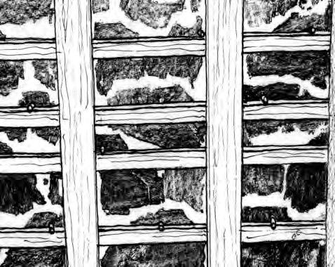
Figure 29b
Figure
Figure
Figure
Figure
Figure
35
28a Figure 28b
29a
29d
29e
29c
width to give the number of courses available for each slate length. Left-over slates are added to the next shorter length. To cover slopes on both sides of a roof the slates might be sorted into odd and even number lengths or simply half the total applied to each side. If the slates are to be fixed with wooden pegs these are inserted before taking them up to the roof.
9.3 Gauging
The position for the first slate course is marked on a rafter at each side of the roof - at the verge, hips or any intervening valleys - and allowing the required eaves overhang. A similar mark is made for the appropriate length under-eaves slate. Then if a scantle stick is being used, the gauge for the longest slate is taken off the stick with a compass and the next course marked above the first. Each of the subsequent gauges are marked on the rafter. However, at each twist - the first course of shorter slates - the next gauging mark using the same compass setting is lowered by the difference in the slate lengths - usually but not always about 25 mm (one inch) – and marked with a letter T. This ensures that the tails of the shorter slates overlap the next but two slates below by the correct amount.
These two steps, marking the courses and then the twist course, are repeated for all the slates up to the ridge. A chalk line is then snapped across the rafters at each mark and the T of the twist courses written on each rafter. The laths or battens are then nailed below the lines and, if necessary, at the twist or near the ridge where the lath gauge is tight their width is reduced to make room for the pegs (Figure 13). An alternative method involves marking the gauges onto two laths which are placed against the rafters on either side of the roof and the lath marks snapped onto the rafters.
9.4 Fixing the slates
The roof is first stacked out with the slates by their appropriate laths. They are then hung on the laths or nailed working one or several courses progressively across the roof and, if wet-laid, bedding them with the minimum of mortar –typically a 25 mm (one inch) bead. Each slate is selected and laid so that the perpendicular joints are approximately central over the slates below (Figure 6).
Sometimes the decision is taken to re-use top-
fixed slates by centre nailing. In this case the slates’ tops must be dressed off to avoid the risk of leaks through the old holes and the head lap and minimum width specified to take into account that the centre nailing renders the slates effectively 50 mm narrower.
10 Rag slating
10.1 The rag slating process
Slating with rags is different from almost all other slating systems in that the slates are nailed directly to the rafters and consequently there are no laths to use to gauge the roof or to work off. Sometimes rag slates are encountered fixed to battens but this is thought to not be original and will certainly be the case if there is underlay installed as well. The slating process involves three steps: sorting the slates by length; determining the number of courses of each length and fixing them on the roof.
The rafters on rag roofs are small – about 50 mm square – but set closer together than battened roofs, at about 300 mm (12 inch) centres. Rag slating is a double-lap system and although historically roofs would be gauged without calculations the normal method using gauge = (length – lap)/2 applies. A head lap of 108 mm (four inches) is most common and given the width of the slates appears to be generous but it was probably adopted to be certain that there was enough lap (shoulder lap) at the slates’ ragged top corners.
10.2 Preparation
Rags slates are usually described as large but really their distinguishing feature is that they are very wide (Figure 29(a)). This is because they are generally laid with the longest dimension horizontal unlike normal slating. As a consequence their grain does not always run north-south in the slates. Slates are usually made with grain in this orientation in order to best resist the stresses they experience on the roof but rags do not break because their thickness combined with the inherent strength of the slate rock is adequate. Rags are not holed before stacking the roof because it is not known where they will overlie the rafters and hence where they will be nailed. So they are only sorted into length sets and the number of courses for each determined before
36
taking them to the roof. Typically they are sorted into seven sets from 610 to 305 mm (24 to 12 inches) long in about 50 mm (two inch) steps.
10.3 Gauging
This is done as work progresses. The eaves are set out as described below and then a line marking the tail of the next course is struck across each preceding course at a point giving the required head lap over the second course below (Figure 29(b)). At the first course of shorter slates the gauge is adjusted as normal to ensure evenly diminishing margins.
10.4 Fixing the slates
The slates are holed for nailing by offering them up to the rafters. The holes are positioned at any convenient point well above the slate below and, because of the difficulty of manipulating large slates, holing is normally done from the back to the bed, the opposite of the normal way. They are usually nailed to two rafters but it is not essential for each slate to rest on more than one rafter because the tails rest on the slates below. If they only overlie one rafter, to make them secure, they are fixed with two nails above each other.
As for all slating, the side lap should be kept as large as possible. This is normally done by setting the perpendicular joints about central over the slate below but with such wide slates the sidelap would still be adequate even if they were substantially offset so the normal central placing does not apply. In practice the slater chooses a slate and determines its position to ensure there is adequate cover over the shoulders in the slates below. If particular slates would not give a generous side lap, a minimum of three inches (76.2 mm) was adopted.
Large rag slates inevitably tend to be a bit uneven or twisted which could cause kicking in overlying courses. To overcome this the heads were thinned, shouldered or notched to allow them to set down between the rafters (Figure 29(c)).
10.5 Eaves
The under-eaves and eaves slates are positioned to give the required eaves overhang – usually 50 or 75 mm (two or three inches). Generally, rag roofs do
not have fascias or gutters so the overhang needs to cast water well away from the wall. The length of the under eaves-slate is the gauge plus the head lap.
10.6 Verges (windspur)
Most commonly verges are formed with a rafter at the outside face of the wall and the roofing slates carried over about 50 mm (two inches). The rafters and purlin ends are protected by scrip slates nailed on tightly under the roof slates as described in Section 8.3 (Figures 19 (a) and (b)) either butted end-to-end or over-lapped. The joints between them and under the roofing are pointed with lime mortar.
10.7 Abutments, ridges, hips and valleys
These intersections are treated in the same way as is described for scantle slating. The main difference is that large slates are not as amenable to tight curves so hips and valleys are simply mitred. For security, wider slates would be selected from the bulk for cutting on the rakes. Most examples seen today are weathered with lead soakers, sometimes with a mortar fillet along the joint, but it is likely that the earliest roofs – 17th century – would have been bedded onto mortar or clay. This would have had a good chance of being successful on hips where water flows away from the joint but on valleys they would be likely to leak or fail completely, needing early or frequent renewal.
10.8 Mortar
Rags roofs are not usually tail-bedded but may have been torched just along the slates’ top edges (Figures 29 (d) and (e)). If rags have mortar at the tails or have been slurried they are most likely repairs to try to prevent the slates slipping when the nails are failing.
37
10 Patent slating
11.1 History
Although this single-lap system was patented by Charles Rawlinson of Lostwithiel in 1772, it appears to be rare in the region. It is seen as cladding in some towns including St Teath, Launceston and Tavistock, and hopefully, there are more to be identified. In spite of its apparent regional rarity, it is a nationally important technique and should always be conserved.
11.2 Construction
The construction illustrated in Figure 30 is from Rawlinson’s patent. The slates overlap vertically but only butt up against each other laterally. The consequent open perpendicular joints are weathered with slate cover strips and glazier’s putty or similar material. It relies entirely on the headlap and the bedding material at the butt joints to be effective. Where it is used as roofing it is always the deterioration of the bedding which results in leaks but this should not be accepted as a reason to change to another slating system. Failed bedding can be satisfactorily replaced with modern seals or sealants19 .
11.3 Durability
A Patent roof’s durability is as long as that of the slates and normally these roofs only need repairs when the seals or bedding fail.
Roof pitches are usually low and because the slates appear to be strong there is a temptation to walk on them for inspections or to look for deteriorated bedding. But, because the spans are large - about a metre, this is the most common cause of cracked slabs. Roof ladders or similar means of spreading the load should always be used.
Provided the slates are not walked on without spreading the load they can be carefully removed and reused. Any losses can be made up with new slates and a flexible mastic with a matching expansion coefficient to slate or a sealing system should be used to reseal the joints.
Used as cladding, the bedding’s deterioration is unlikely to lead to discernible leaks and seldom
needs repairs until any iron fixings fail.
11.4 Preparation and gauging
The slates are all the same size and nominally the same thickness so they do not need to be sorted. Any thickness variation, and consequent gaps under the cover strips, are accommodated by the putty.
Gauging is done in the same way as rag slating - striking head lap lines on each course as work progresses - or by striking lines across the rafters for positioning the slates’ top edges.
11.5 Fixing the slates
A variety of wooden pegs, nails - including lead nails, and screws have been used to fix the slates and cover strips into the supporting structure. Once in place the slates are drilled for the fixing holes and the fixings applied. If lead nails are used they are inserted and wrapped around the rafter from below. The lateral gap between the slates is filled with glaziers putty or a modern equivalent and a bedding strip applied where the next course will overlap. This can be in short, staggered lengths to create gaps for ventilation from the rafter space. Once all the slates are in place the cover strips are similarly fixed with putty or seals.
38
Figure 30 Rawlinson’s Patent slating sytem seems to be rare in the region but is nationally important and should be conserved.
Figure 31 Slate-cladding is common on wind- and rainexposed walls especially on timber-framed upper stories where the lower storey is stone:

(a) The bottom courses are always given a good kick to throw water away from the foundations (St Ives).Various methods are used to finish the slating around windows with:
(b) an architrave (Ashburton) or (c) the slating returned into the reveal (St Mabyn).


Figure 32 Cladding has often provided an opportunity for decoration:

(a) using shaped slates (Bridestow) or (b) a mix of colours (Dartmouth)
 Figure
 31b
Figure 32b
Figure 32a
Figure 31c
Figure 31a
Figure
Figure 31b
Figure 32b
Figure 32a
Figure 31c
Figure 31a
39
30
12 Wall cladding
12.1 Application
Slate cladding is common on wind- and rainexposed walls throughout the region especially on timber-framed upper storeys where the lower storey is stone (Figure 31). Many examples were not original features of the building but were added to alleviate damp walls.
12.2 Ground work
The slates are fixed directly to mortar render or to laths or battens which in turn are nailed directly into the mortar joints, or into the masonry itself if it is soft like mudstone or shillet or to counterbattens nailed to the wall. Historically, wrought iron nails were used for batten or counter-batten fixing which held well when they rusted but eventually corroded away or failed due to rustjacking.
12.3 Fixing
The slates are pegged or nailed directly to the mortar or to the battens and bedded in mortar. The slates are usually laid closely together laterally but are sometimes spaced out to promote air circulation behind them. They can be laid with the bevel edge inward facing to provide a better key to the mortar or as normal, bevel outwards. Mortar for direct fixing is laid in two coats. The first is allowed to set, the second is then laid and the slates pressed into and pegged or nailed into the first coat. The mortar mix is critically important to ensure good wind resistance20 .
12.4 Details
The eaves are given a large kick (springing) to cast water well away from the lower wall and to allow the slates in successive courses to sit tightly together (Figure 31(a)). Historically, the slates at external angles were not soakered but were carried slightly beyond the opposite face. Soakers should be used today. wAround windows the cladding is butted up to an architrave or, if the window is deeply set into the walls, the cladding is returned on the reveal (Figures 31(a) and (b)). Cladding has often been used as an opportunity for decoration using shaped or coloured slates (Figures 32(a) and (b)).
13Maintenance
13.1 Deterioration
Slate roof deterioration is usually a long-term process and even though repairs can be carried out for many years routine maintenance will significantly delay the need to strip and re-slate. The key is to check often - perhaps twice a year, inside and out if at all possible - and to act quickly. An unattended leak can result in timber rotting or other fabric damage which will seriously exceed the cost of repairs. It is particularly important to keep rainwater gutters - especially horizontal lead gutters - and downpipes clear of debris. Insulation is also a potential source of dampness because it can cause moist air to condense onto woodwork so it should not be assumed that dampness always indicates a slating problem.
13.2 Repairs
Missing slipped or broken slates should be replaced as soon as possible. If they are pegged it will probably be possible to lift or rotate adjacent slates to slide a new slate of similar thickness into place. However, this will break any torching so this should be replaced as well. If the slates are nailed then a slater’s ripper should be used to cut or drag out the nail. The replacement can be fixed with a hook, copper tingle or peg. For repairs to large areas a triangle of slates should be stripped so that all except the apex can be refixed with pegs or nails and only the top one(s) will need a tingle or similar fixing. For a temporary (emergency) repair single slates can be simply bedded in lime mortar but a proper repair should be done as soon as practicable.
13.3 Mortar
Where long established mortar bedding is crumbling or falling away it can be repointed but this is usually only a temporary reprieve as the lath nails are probably failing as well and repointing places more stress on them. Slurrying roofs is a policy of last resort. Although it is traditional in the region it is not a good technique because it can eventually cause the complete failure of the roof with collapsed battens and rotting of the structure and far more cost to repair than reslating. When the battens fail large areas of slating will slip forming riffles (Figure 11).
40
At this point the roof will be beyond practical repair and should be stripped and reslated. Fallen torching should be renewed because it holds pegs in place, helps prevent slates being lifted by high winds and protects laths from water damage. Ridge and hip tiles may need re-bedding and if the bed is not exposed along the edges an NHL 3.5 mortar is suitable. Where it is exposed it will need to be stronger NHL 5, for example, or the NHL 3.5 bedding mix can be pointed up.
13.4 Bi-annual checklist
• Internally check for water-staining or other signs of leaks. These may be much lower on the roof than the leak.
• Clear gutters and downpipes, pitched and horizontal valleys and secret gutters.
• Replace slipped, broken or missing slates.
• Check if ridges and hips are secure.
• Check leadwork – look for wrinkles and cracks, cuts from slipped slates and flashings coming out of chases.
• Are mortar beds, fillets or flaunchings cracking or insecure?
• Are roof penetrations such as for solar panels leaking?
• Ensure insulation is not blocking ventilation routes for example at the eaves or ridge.
14 References
1 Technical guidance on fixing single size (tally) slates is available in BS 5534 Code of Practice for Slating and Tiling and the Construction Industry Training Board manual CTP 036/6.
2 Common slating is distinct from the externally similar technique of Three-and-a-half-pin scantle slating with mounters at the eaves and often with large verge slates. “They were sold by the thousand with forty two small rags called prickers for the eaves.” John Jenkins 1888 Delabole slate quarry: a sketch by a workman on the quarry.
3 Blue slates at the quarry, 3s. 6d. per thousand; for the ordinary rough undressed slates, great and small; running from 4 to 12 inches wide and 8 to 18 inches long, when dressed. The large eaves slates – provincially rags – some of them two feet square, when dressed, are sold at 2s. 6d. a dozen; rough at the quarry.
The price of dressing, or cutting slates into the required form, is 20d a thousand. The entire workmanship, of dressing, pinning, pins, laying on in mortar, is 6s. a square of 100 square feet: without pins, 5s. 6d. per square. A square of slate roofing takes about a thousand slates.
Oak Timber – 15d. a foot Ash timber – 1s. to 14d. a foot Lime – 5d. a bushel Mason’s wages – 18d. a day, and a quart of cider. Carpenter’s wages - the same. Marshall, W, (1796) The rural economy of the West of England including Devonshire and parts of Somersetshire, Dorsetshire and Cornwall, vol 1, London, Nicol.
4 Scantles. Small pieces made from the trimmings of slate, not dressed, used in Cornwall. Richardson, C S, (1854) The Slate Quarries of Vermont in The Mining Magazine, New York, Vol 2, pp271-282.
5 With respect to roofing slates, there are many quarries in the district, generally supplying their immediate neighbourhood, and which are rarely exported, with the exception of the Delabole and other slates near Tintagel. In the northern grauwacke there are scarcely any of importance; some slates are, indeed, raised near Treborough, but the quantity is not considerable. Slates are worked in the carbonaceous series at Ashbrittle, on the north, and in the same series near Coryton and Launceston, on the south; the chief quarries, in the vicinity of Launceston, being near Newchurch farm, Tresmarrow and on the south of Bad Ash. Slates are also raised in the range of the latter beds on the west. There is much roofing slate in the grauwauke ranging round the southern part of Dartmoor. There are quarries at Ingsdon, near Bickington; at East Down, between Ogwell and Ashburton; at Bulland, on the south of the latter place; near Wash, on the east of Buckfastleigh; at Bow, on the north of Staverton; at Tigley and Moor, near Rattery; at Porter Bridge, near Harberton Ford; at Brixham; at Wood and Ludbrooke, near Ugborough; at Cann Quarry, near Boringdon Park (to which a canal has been made up the Plym), and extensive works have been carried on; at Leigham, on the east of Egg Buckland; and at Mill Hill, near Tavistock. There are slate-quarries in Cornwall, at Hay, near Callington; at Kerney Bridge, on the south of Linkinghorne; at St. Neott’s; at Newporth,
41
near Morgan; at Penquean, near Wade Bridge; and, at a few other minor places. The great Cornish quarries are at present those of Delabole, and the vicinity of Tintagel; including a large one on the sanding road between Penpethey and Pentafridle. de la Beche, H, (1839) Report on the Geology of Devon and Cornwall and West Somerset, London, Longman, pp 502-503.
Grauwacke is a variety of sandstone composed of poorly sorted angular mineral grains in a compact fine grained matrix.
6 An extensive list of local newspapers including articles on slate quarries can be seen at Exeter University on http://projects.exeter.ac.uk/mhn/Newspapers2008. htm
7 Shipments to Kidwelly in South Wales are recorded in 1478-79 and 1480-81. ‘... stones called slates, cost 20d. per thousand and payment for carriage of the said 10000 stones from Ilfracombe to Kidwelly price per thousand 12d. - 26s. 8d.’ and ‘payment for 10000 stones called slatstone bought at Ilfracombe price per thousand 20d. - 16s. 8d.’ National Archives Duchy of Lancaster accounts DL 29/584/9251 and DL 29/584/9253.
8 ‘... the Devonian strata in north Devon and Somerset have afforded rough slates strong and sound, but with a rather wavey cleavage surface, and not capable of being split at all thin. They have been worked in a small way about Countisbury and Treborough, in the Bredon Hills. As a rule these slaty rocks are too much crinkled and folded to make good slate.’ Howe, J. A, (2001) The Geology of Building Stones, Shaftsbury, Donhead Publishing Ltd. First published in 1910.
The Countisbury source may be in the Lower Devonian, Lynton slates.
9 ‘The stone of Cann Quarry is a very firm and durable slate of a kind of greyish-blue; it does not run into such fine and even laminae as the Dedibole [sic] and Millhill quarries, as it frequently splits out wavy and irregular thick; but there is none, I believe, that can exceed it in strength and durability: and I have a great deal now on the roof of my house, which was taken down after having remained on it in seventy years, and is now replaced, being, if possible, still more
firm and stronger than even what is taken fresh from the quarry: even the same pin holes served again.’ Polwhele, R, (1793-1806) The History and topography of Devonshire in three volumes, Exeter Trewman, Vol 1, p52.
Polwhele is quoting Yonge of Puslinch House, Yealmpton.
10 The Level 3 NVQ Diploma Roof Slating and Tiling includes random slating. Successful completion entitles candidates to apply for the Construction Skills Certification Scheme (CSCS) gold card covering craft skill, job knowledge and understanding. They can extend this with the Level 3 Heritage Special Apprenticeship Programme for Roof Slating and Tiling which covers the historical, theoretical and technical knowledge and practical skills in historic building conservation, repair and restoration which leads to the CSCS card endorsement Heritage Skills. These are the appropriate qualification for slaters who work on scantle and rag roofs There are similar systems for construction site management of conservation work and for conservation consultancy (Table 3). These qualifications may be required by clients or be included in grant conditions.
11 Historic England: Energy Efficiency and Historic Buildings - Application of Part L of the Building Regulations to historic and traditionally constructed buildings. First published 31 March 2011.
12 Whilst the w itself does not contain a classification of slate durabilities an explanation of the tests is available at See www.stoneroof.org.uk/ tests2.html and two organisations have established their own requirements or guides:
National House-Buildings Council (NHBC) www. nhbc.co.uk/Builders/Technicaladviceandsupport/ Slates-nomoregreyareas/
National Federation of Roofing Contractors NFRC guide TB4A Selecting Natural Slates for Roof Covering. www.nfrc.co.uk
13 National Federation of Roofing Contractors Technical Bulletin Selecting Hooks for Slating.
14 ‘Now the pins are put firmly into the holes and
42
the slates piled so that they will stand without toppling: so many with pins lapping one end and so many the other, and still in sets of equal lengths.’ Boyle, V C, Scantle Roofs, in Devon and Cornwall Notes and Queries 26, p10-15
15 Historic England series Energy Efficiency in Historic Buildings:
- Insulating pitched roofs at rafter level - warm roofs.
- Insulating pitched roofs at ceiling level-cold roofs. - Insulating dormer windows.
16 Viscar in Wendon 1834: ‘Roofs with best scantle slate on Norway heart laths at the four-and-a-halfpin and rag eaves double laid in lime and sand half Aberthaw and half common lime.‘ Cornwall Records Office X634/52/2.
Aberthaw was a strong hydraulic lime.
17 Further advice on selecting mortars is included in Allen, G C, Allen, J, Elton, N J et al (2003) Hydraulic Lime for Stone, Brick and Block Masonry. Shaftesbury: Donhead Publishing Ltd. See particularly Tables 9 and 10 regarding mortar selection for durability giving durability classes. Holmes, S and Wingate, M (2002) Building with Lime: A Practical Introduction, revised edition, London: Intermediate Technology Publications (now Practical Action). Chapter 5 is particularly relevant.
British Standards Institution (2015) Building Lime – Part 1: Definitions, Specifications and Conformity Criteria, BS EN 459-1, London: BSI
18 ‘At the gable ends the scantle slates may sail out over the bargeboards as in later roofs, but in windy places the barge-boards come up outside all, and a capping piece about 3 ins. wide is nailed down, covering ends of slates and top edge of bargeboard.’ Boyle, V C, idem 26, p10-15
19 Information and pictures of Patent slating can be seen at www.stoneroof.org.uk/historic/Historic_Roofs/ Patent_slating.html
20 Describing West Devonshire: ‘In situations exposed to westerly winds the walls of dwelling houses of every material are frequently guarded with slates, put on scale-wise, as upon roofs, to prevent the “sea air” from penetrating the walls,
and giving dampness to the rooms. In towns, the shells of houses are not uncommonly built of wood; lathed; plaistered; and slated. Houses fronted with well coloured slate, put on neatly, and with “black mortar” (namely cement, among which pounded forge cinders have been freely mixed), are not unsightly. But smeared in stripes or patches, with white mortar, ouzing out of the joints, and spreading partially over the surface, the appearance is filthy.’ Marshall, W., idem.
14 Other advice
14.1 Contacts
Where slating work is being considered, the SPAB may be able to suggest the names of suitable contractors and professionals or advise on courses that teach practical skills. Local authorities may also have lists of architects, surveyors and slaters with experience in local slating. Architects can be chosen from the list of Architects Accredited in Building Conservation (AABC) www. aabc-register.co.uk/ and conservation accredited surveyors from the RICS www.rics.org/. The Institution of Structural engineers CARE scheme lists structural engineers www.istructe.org.
National Federation of Roofing Contractors Ltd
Roofing House
31 Worship Street London, EC2A 2DY Tel: 020 7638 7663 www.nfrc.co.uk
Historic England South West region 29 Queen Square Bristol BS1 4ND 0117 975 1308 www.historicengland.org.uk/about/contact-us/ local-offices/south-west/
14.2 Advice on protection of animals and plants
DEFRA
APHA Field Services Isca Building Manley House Kestrel Way Exeter Devon EX2 7LQ Tel: 01392 266 375
43
Natural England Bristol
1st Floor
Temple Quay House 2 The Square
Avon
Bristol BS1 6EB Tel: 0300 060 6000
Glastonbury Shapwick Rd, Westhay Glastonbury BA6 9TT Tel: 01458 860120
Blandford Rivers House
Sunrise Business Park Higher Shaftesbury Road Blandford Forum DT11 8ST Tel: 0300 060 6000
Bridgwater Rivers House E Quay Bridgwater TA6 4YS Tel: 0300 060 6000
Exeter Level 9
Renslade House
Bonhay Road
Exeter, EX4 3AW Tel: 0300 060 1110
Taunton
Riverside Chambers Castle Street Taunton TA1 4AP Tel: 0300 060 2570
Truro
Polwhele
Truro
Cornwall TR4 9AD Tel: 0300 060 2544
The Bat Conservation Trust
5th floor
Quadrant House 250 Kennington Lane London SE11 5RD Tel: 0845 1300 228
The Barn Owl Trust Waterleat Ashburton Devon TQ13 7HU www.barnowltrust.org.uk
14.3 Further reading
English Heritage, (2013) Practical Building Conservation: Roofing, Farnham, Ashgate Publishing Ltd.
Bennett, F and Pinion, A., (2000) Roof Slating and Tiling. Shaftsbury, Donhead Publishing Ltd, Boutwood, J., (1991), The Repair of Timber Frames and Roofs, SPAB Technical Pamphlet 12, London, SPAB.
Cox, J and Thorp, J, (1991) ‘Authentic Slating in Devon’, Transactions of the Association for Study of in the Conservation of Historic Buildings, Vol 16, pp3-12, London.
Davey, N, (1971) A History of Building Materials, London, Phoenix House Ltd.
Setchell, G T and Setchell, M C, (ND), The Delabole System of Random Slating in Diminishing Courses, Delabole Quarry.
Emerton, G, (1988) Old Roofings, Nantwich, Johnsons Ltd.
The Manifesto of the Society for the Protection of Ancient Buildings
Hughes, T G, Historic roofs in Britain and Ireland www.stoneroof.org.uk/historic/Historic_Roofs/ Introduction.html
Hughes, T G, Slate and Stone Roofing Glossary www.stoneroof.org.uk/historic/Historic_Roofs/ Publications_files/Stone%20slate%20glossary.pdf
44
Glossary
This glossary includes terms mentioned in the text many of which are specific to the region.
Back: Upper face of the slate when laid on the roof, visible from outside the building. Antonym: bed. Backer: narrow slates laid roughly centrally over a wide slate to accommodate the increasing number of slates in each course as work progresses up the roof. Synonym bachelor
Batten: Sawn wooden support for hanging or nailing stone slates. Synonym: lath. In slate and stone roofing guides the word lath is usually reserved for riven supports.
Bed: Lower face of the slate when laid on the roof, visible from within the roof. Antonym: back Bedding: Layer of mortar laid over the back or face of a slate, into which the tail of the slate in the next course above is pressed.
Break iron: Long iron blade set into a wooden block over which slates are dressed to shape and size. Smaller versions are used on the roof driven into a rafter. Synonym: slater’s dog.
Calcite: form of calcium carbonate which can occur in layers or veins in metamorphic slates.
Carbonate: calcium or magnesium carbonate potentially deleterious inclusion as veins or layers in metamorphic slates.
Centre-nailing: Fixing of slates to battens by a nail at each side of a slate, on a line approximately halfway up the slate.
Cleavage: Slaty cleavage is developed in fine grained rocks following metamorphism. Under the influence of pressure and heat the pre-existing minerals are partially re-crystallised and aligned perpendicular to the pressure. Slates cleave parallel to these platy minerals.
Cleat: spike bent at right angles and driven into the rafter to hold thin laths with out splitting them. Synonym, cask / barrel / cooper’s hook, tenter hook.
Collar and tie valley: A valley of alternating courses of mitred slates (the collar) and a single long, narrow slate (the tie) all laid triple-lapped.
Common slating: Wet-laid small slates pegged over laths in diminishing courses at one-third lap so that each slate just laps the peg of the slate in the second course below, and using large slates at the eaves.
Course: A single row of slates across a roof or wall.
Coursing: See gauging.
Crest, crece or cresting: Ridge stones or tiles.
Crow steps: slate or stone set into a wall to throw water away from an abutment synonym feather, dropper
Diminishing: Slating with a range of lengths on one roof. The system whereby random sized slates are sorted by length and laid with the longest at the eaves, diminishing to the smallest at the ridge. It is essential that the minimum head lap is maintained when there is a change of slate length between two courses. This also ensures that each successive margin is the same size or smaller than those below Double-lap: Slates laid so that each course overlaps the course next but one below. See triple-lap and thirds.
Dressing: Trimming slates to square the edges. Traditionally done with a sax over a break iron or in the quarry with rotary guillotines.
Dressing iron: Synonym for break iron.
Dropper or feather: Flat stones or slates set into a wall or chimney to protect the vulnerable slating abutment from water penetration.
Eaves course or eaves slate: Short course laid at the eaves under the first full course. In pin slating there are sometimes two eaves slates. Synonym: under eaves.
Ellen: A roofing slate.
End lap: See head lap.
Feathers: Synonym for droppers
Full torching: application of mortar to the underside of the slates between the top and bottom edges of the laths or
45
15
battens. Synonym single torching. Gauge: The spacing between the top edge of a lath or batten and the next one on a roof or wall. Synonym: lath or batten gauge. See twist.
Gauging: Setting out the laths to provide the specified head lap or margin. Synonym: coursing. See twist.
Half-torching: Mortar applied to the underside (bed) of the slate at its head from the inside of the roof after the slating is completed.
Hammer, rag hammer, pin hammer or slater’s pick: Hammer with a blunt end for nailing and a pointed end for holing.
Head: Top edge of the slate when laid on the roof.
Head bedding: setting the head of slates in a bed of mortar across part or the full slate’s width.
Head-fixing: Slates hung on or nailed to laths or battens with wooden pegs or nails positioned close to the slate’s head.
Head lap: The length by which the tail of a slate overlaps a slate in a course below. In head-fixed slating it is the overlap of the peg hole or the top of the lath. In centre-fixed slating it is the overlap of the head of the slate. Synonym: end lap.
- single-lap: course two overlaps course one.
- double-lap: course three overlaps course one. Slating in thirds is double-lapped.
- triple-lap course four overlaps course one. Three- or four-pin slating is triple-lapped.
Helling, hailing or healing: Roofing stone or slate; to slate a roof
Horse: Long wooden block into which a break iron is fixed.
Lath: A strip of riven (split or cleft) timber, rectangular in cross-section, on which slates are hung. cf batten which in slate and stone roofing guides is usually reserved for sawn supports.
Lath hatchet: Hatchet with a blade for cutting laths to length and a hammer head at the back of the blade for nailing the laths to the rafters.
Lap: Amount by which the tail of a slate overlaps a slate in a course below. See head lap and side lap.
Margin: Portion of the back of the slate visible when fixed on the roof, from the tail of one slate to the tail of the slate in the next course above.
Metamorphism: The action of pressure and temperature on rocks or sediments in the earth’s crust, producing mineralogical and structural changes.
Mounter or mounter slate: Large slates laid at the eaves of roofs for one or two courses and often fixed directly to rafters rather than laths or battens. Ovvies or hovies (offies): Double course of slates at the eaves (under ovvies) or ridge (top ovvies).
Patent slating: single lap system where slates are fixed to rafters, especially on cast iron frames. Patent ridge: ridges made from slate. They have two forms: a birdsmoth roll top which is fixed over two wings or a wing and roll mating with an opposite wing.
Peg: Small piece of wood roughly square in section and may be tapered. Used for hanging slates from laths.
Peggy: Small slate, typically, in West Country slating, slates ranging from 305 to 152 mm (twelve to six inches) long.
Pig course or gaper: A large margin above a shorter one, the result of not applying the twist at the change course.
Pin: Synonym for peg;
Pin pointing: Mortar applied to or around slate pegs to hold them in place and to prevent them tilting.
Pin slating: System for gauging roofs by division of slate lengths into fixed proportions. The normal division is into sevenths whereby the head lap is one seventh and there are three margins of two sevenths each in a set of four successive courses. This division can be described as three-and-a-half or four-and-a-half-pin.
Prickers: Synonym for mounters
Pricking up: Setting out the laths or battens on the roof. Pyrite, pyrites: generic name for a group of metal sulphides found in some slates often collectively known as oxidising pyrites or oxidising metallic minerlas. It is also the specific name for one form of iron sulphide FeS2.
Rag slate: Large slate squared on three sides and with a ragged top.
46
Rag slating: Rag slates nailed directly to rafters. There is some evidence that rag slates have been nailed or pegged to boards historically.
Random slate: Slates of varying lengths and widths. In west country slating, usually restricted to mean slates longer than 305 mm (twelve inches).
Rap: Batten or lath.
Rapping: Battening, lathing.
Riffle: A hole especially a long gap in slating where the lathing has failed and one or more courses have slipped. Usually a consequence of grouting or slurrying.
Rip or ripper: Long flat tool with an offset handle for cutting or withdrawing slate nails.
Riving: Piece of slate split to thickness but not dressed to size.
Sax or zax: Bladed tool with an offset handle used for dressing slates to size and optionally with a spike to make a fixing hole.
Scantle, scantle gauge: Length of timber marked with slate lengths and their corresponding lath gauge Scantle rod: length of timber marked up with the slate gauges. A pair of rods are placed at either side of the roof and the gauges struck onto the rafters with a chalk line
Scantle slates: Small slates typically ranging in length from 305 to 152 mm (12 to 6 inches) long and of random widths,
Scantle slating: Systems of wet- or dry-laid slates set out (gauged) and laid in diminishing courses, so that each slate laps the head of the slate in the third course below. Also known as three-and-a-half and fourand-a-half-pin.
Scrip: Slates fixed to exposed verge rafters and purlin ends.
Shillet: building shale able to receive a nail fixing for cladding slates.
Side lap: Horizontal distance between the side edge of a slate and the side edge of the next slate in the course directly above or below.
Slate length: In top-fixed slating, the dimension from the fixing hole to the tail of the slate;
- in centre-nailing, the full length of the slate from its head to its tail.
Slater’s dog: See break iron
Springing: See tilt
Square: One hundred square feet of roof area. Historically, the basis for coverage and supply of slates.
Swept valley: A valley formed with several tapered slates, with the narrow end down, laid without a break across the intersection of the two slopes
Tail: Bottom edge of the slate when laid on the roof.
Tally slates: Slates all the same size.
Thirds: Setting out slates on the roof so that the head lap and hence margin is one third of the slate length. See double-lap.
Tilt or springing: Lift provided to ensure the slates are correctly supported and/or lay closely onto their neighbours:
- on the main areas of the roof slope, the tail of each slate rests on two (in pin slating, three) thicknesses of slate in the courses below. At the eaves, the first full course rests on one thickness less - the eaves slate(s). Essentially, the tilt replaces the missing thickness but a little more is needed to allow a slate to bridge between the lath at its head and the underlying slate at its tail. The required amount of tilt can be provided by a tilting fillet, by building up the wall head underneath the eaves course or by setting the rafter back from the outside edge of the wall. Fascia boards can also be used to provide tilt but historically they were not used on slate roofs.
- at the eaves course and at back abutments - the lift provided to ensure that successive courses lie correctly without gaps at the tail
- at verges and side abutments the lift provided by raising a rafter relevant to the roof slope or by use of a batten or tilting fillet to tilt the slating into the roof thus directing water onto the slope and away from vulnerable abutments.
- at lead valleys – use of a wooden fillet to support the edge of the valley slates and to fill the gap between the lead and the slates thus preventing water driving into the slating. The lead must be laid over the tilt.
Tingle: Metal strip used to replace a slipped slate. It is nailed to a lath or batten, the replacement slate is
47
slid into place over it and the tingle turned up to hook the slate’s tail.
Torching or tiering: Mortar applied to the underside (bed) of the slate from the inside of the roof after the slating is completed. It serves to check the entry of wind-blown snow or dust through the slating. In full torching the mortar is applied between the laths or covering the laths. In half torching the mortar is only applied at the top edge of the laths.
Triple-lap: The overlap formed by the tail of a slate lying over the slates next but two courses below.
Triple-lapping: Slates laid so that each course overlaps the course next but two below. See double-lap.
Turnerising: The damaging and disfiguring mid-twentieth century practice of spreading a mesh and bitumen mix over the top of the slates to prolong the life of a failing roof.
Twist: Decreasing the lath gauge in random slating at the first shorter course to maintain the minimum head lap. If the twist is not applied there will be courses with larger margins than lower courses and the head lap will be smaller than intended and may leak.
Under, under eaves slate, under course: the first, short course of slates laid at the eaves.
Valley: The sides or bottoms of two adjacent or opposing roof slopes. Vapour control layer: A material used to limit the passage of water vapour between parts of a building.
Vapour permeable membrane: Sheet material which allows the passage of water vapour between parts of a building.
Windspur: Synonym for verge.
Worm: lead welt
Wrestlers: Vernacular ridge detail in which sets of notched slates interlock along the ridge.
Zax: See sax.
48
The Society for the Protection of Ancient Buildings (SPAB) believes old buildings have a future. From cottages to castles and from churches to cathedrals we are here to help buildings and the people who care for them. Through our unique training schemes, courses, advice and research we help people put our expertise into practice.
Founded by William Morris in 1877, the SPAB was established in response to the work of Victorian architects whose enthusiasm for harmful restoration caused irreparable damage. Today the SPAB encourages excellence in new design to enrich and complement the built historic environment. We train new generations of architectural professionals and building craftspeople to shape this landscape with sensitivity and skill, and we play a statutory role as adviser to local planning authorities. In our casework we campaign actively to protect old buildings at risk.
SPAB: hands on history. Join today to support our positive, practical approach to building conservation.

The content of this advice note is offered in good faith but neither the author nor the Society can accept responsibility arising from incorrect or incomplete information that may be included. The use of traditional materials may incur risks different to those associated with modern materials. Manufacturers’ and suppliers’ guidelines should always be observed. This document should be seen as a contribution to a continuing debate and we welcome comments.
Thanks for advice on the preparation of this paper are due to the SPAB Technical Panel and the following: Erica Adams, Paul Bedford, Oliver Bosence, Rebecca Child, Jo Cox, Jan Clarke, Roger Green, Bob Harris, Val Harrison, Gavin Hickson, Philip Hughes, Richard Jordan, Douglas Kent, Andy King, Graham Lott, Stuart Meigh, Linda MacLean, Dave Norish, Richard Roberts, Alistair Rule, Viv Stratton, Simon Thorpe.
The author is indebted to Stafford Holmes for the section on mortar.
Edited by Terry Hughes
Drawings by Ray Harrison and Terry Hughes
Produced by Terry Hughes
© Terry Hughes/SPAB 2016 ISBN 978-1-898856-33-7
A charitable company limited by guarantee registered in England and Wales
Company No 5743962
Charity No 111 3753
Scottish Charity No SC 0392214
VAT No 511 121602
49
Plumbing Leadwork: Joints and Pipes

SPAB Technical Advice Note
Peter T J Rumley MA, DPhil, MA, FSA, MCIfA
The Society for the Protection of Ancient Buildings
37 Spital Square London E1 6DY 020 7377 1644
info@spab.org.uk www.spab.org.uk

Contents
This Technical Advice Note explains the basic jointing techniques and methods of pipe fabrication used in plumbing leadwork, ie the making, fixing and maintenance of pipework for building services, which require a broader range of skills from those used in lead sheetwork for roofs and cladding. Historically, lead pipes were used for the supply of water and gas, as well as the disposal of rainwater and foul water.
Materials such as cast iron, copper and plastic having replaced lead, the construction industry no longer offers training in plumbing leadwork. the loss of such traditonal skills is of great concern to the SPAB. Much historic plumbing leadwork has been lost or harmed through poor quality repair work or inappropriate replacement, particularly in hidden areas, due to a lack of conservation understanding and traditional plumbing craft skills. The skills of the plumbing leadworker remain essential for the conservation of historic leadwork.
1 Introduction
3
2 Joints in leadwork 3
3 Pipe fabrication
4 References
5 Other advice
Cover image: Historic lead waste water pipe with associated collar and brackets. Photo: Douglas D Kent
SPAB Plumbing Leadwork: Joints and Pipes2
.......................
....................... 7
....................... 10
....................... 10
1 Introduction
When undertaking repairs to historic plumbing leadwork, it is important to copy the original jointing methods and not to ‘improve’ upon them, as to do so is to change the fundamental nature of the historic piece. It is equally important not to follow bad examples set by earlier repairs carried out with inappropriate techniques or poor workmanship.
Work on lead pipes entails the use of techniques different from those generally recommended for lead roofing. In particular, the tradtional skill of solder wiping is often the suitable method for forming joints in lead pipwork as opposed to leadburning (lead-welding), which tends to be advocated for patch repairing lead sheet roofs. Other traditional skills associated with plumbing leadwork include lead pipe bending and pipe construction.
2 Joints in leadwork
2.1 Types of joint
Three hot processes have been used historically for jointing leadwork:
• Soldering.
• Wiped soldering.
• Leadburning.
2.2 Soldered joints
Soldering entails the use of an alloy, or ‘solder’, to join metal without heating it to its melting point. The melting point of lead (327.5˚C) is reduced by the addition of tin. The proportions of tin and lead can be varied to produce a range of alloys, each with a different melting point, which can be exploited by the plumber for different purposes. Table 1 gives the usual ratios and their respective applications.
Blowpipe
Tinman’s
Plumber’s 2:1
solder used for copper-bit jointing, tinning for pre-jointing, tinning for decoration and
coarse solder used for wiping all kinds of joints; has a working plastic range between 182˚C and 262˚C
SPAB Plumbing Leadwork: Joints and Pipes3
Solder Lead:tin Melting point Application
1:2 171.1˚C A fine solder used for delicate work
1:1 187.7˚C A fine
general applications
227.2˚C A
Table 1: Lead:tin ratios for soldering
There is as much art in fixing the joints in place, ready to be soldered, as there is in the soldering itself. ‘Solder-tacking’ is the use of spots of solder to hold the edges of an item together before it is finally soldered. Before this is done, however, all surfaces to be joined are cleaned by scraping back to bright metal using a shave hook.1 They may be smeared with flux, which assists jointing by preventing oxidation (dulling of the bright surface of the lead, which can occur very quickly after cleaning). Only noncorrosive fluxes, such as rosin or tallow, should be used.
When plumbers had to rely on coal or charcoal for heat, two soldering irons were used to maintain soldering temperature, one being used to apply the solder while the other was being heated by the plumber’s mate. Today, an oxyacetylene torch is used.
Soldered joints can be susceptible to thermal movement. However, items fabricated from smaller sheets of heavier-gauge lead –rainwater heads, pipes and cisterns – are less likely than lead sheet roofing to suffer from thermal stress.
2.3 Wiped soldered joints
Wiped soldered joints were used extensively in lead pipework for water supply and rainwater drainage (see figure 1), and for making decorative rainwater heads. The wiped joint is made by manipulating a mass of molten solder into a neat shape over a joint and smoothing it with a moleskin cloth2 before the solder solidifies.
The tools required for wiped solder joints in making items from sheet lead are a: melting pot, ladle, hammer, shave hook, rasp, mallet and dresser. In addition, boxwood turnpins are used to open out the ends of the pipes; they come in various diameters and taper to suit different pipe sizes. The materials needed are: plumber’s solder (see table 1), flux and ‘plumber’s black’ –a masking fluid made of size (animal skin glue), whiting and lamp black mixed together to a creamy consistency.
For safety reasons, this work is nearly always completed on the bench and rarely in situ. Fixing rods are nailed into the bench and the item is tied to them to hold it in place. Lead sheet must be fixed firmly in position ready for soldering, either by solder tacking and/or spikes driven into the bench.
It is sometimes necessary to wipe joints in situ where access is restricted. However, there is often enough give in lead pipes to pull them away from the wall so that the solder can be wiped around appropriately.
To limit the spread of the solder and prevent it adhering where not required, the surface of the lead is masked (‘soiled’) using plumber’s black. The areas to be joined are cleaned with a shave hook, heated with a blow lamp and smeared with flux. The solder is then ladled over the joint
 Figure 1: Lead water pipe for WC with wiped soldered joint below cistern.
Photo: Douglas D Kent
Figure 1: Lead water pipe for WC with wiped soldered joint below cistern.
Photo: Douglas D Kent
SPAB Plumbing Leadwork: Joints and Pipes4
and wiped neatly with the moleskin cloth. It will splash everywhere but will fall away from the soiled areas. Solder that flows on the joint may be wiped neatly from the outside. In box-like items such as rainwater heads, this type of joint is particularly strong, as the solder will form a right-angled triangle along the corner seams, supporting the ‘walls’ of the box from within.
Wiped soldered joints on soil, waste and vent pipes are made with the same tools and materials as those used for sheet items. The three basic types of joint are:
• Underhand wiped.
• Upright wiped.
• Branch wiped.
(See figure 2.)
In underhand wiped joints, the ends of the pipe are cut square, and a turnpin and mallet are used to open out the female end. The male spigot end is tapered with a rasp. Each pipe is then soiled with plumber’s black. When dry, the soiled ends are cleaned, and flux is applied to the cleaned metal. The pipes are fixed in position and the solder is poured over the joint with a ladle while a moleskin catch cloth is held underneath the pipe. The solder is roughly and smartly wiped around the joint. The wiping must be timed so that the solder sticks to the surface where intended. A smaller moleskin wiping cloth is used to mould the joint to the correct shape. A thin strip of moleskin is worked around the pipe to finish off and shape the joint lengthways.
The same tools are used to make upright wiped joints, with the addition of a splash stick and a cardboard collar; the latter is fixed below the joint to catch the dripping solder. The pipe is prepared in the same way as for the other wiped joints. The solder is splashed up from the ladle onto the joint using the splash stick and wiped into position with moleskin. The soiled collar and excess solder are removed as soon as possible.
Branch wiped joints: A damaged pipe may be released from a joint by applying a gentle flame to the solder to melt it. The joint must be cleaned before a new section of pipe is inserted. Both pipes are prepared as described above. A pair of compasses is used in conjunction with a scribing plate (a thin, flat piece of brass that holds the compasses in the correct relationship to the curved surface of the pipe) to incise the line of the angled joint into the plumber’s black. This masking fluid is then scraped back to the scribed line, enabling the plumber to achieve an accurate joint between the pipes. The wiped solder is formed into a neat, slightly concave, shape. (See figure 3.)
2.4 Leadburning
The technique of using a hot welding iron to fuse the lead joint without the use of solder or flux was known in Roman times, and is also mentioned in medieval building accounts. It was further developed in the early 20th century with oxyacetylene equipment, and is now primarily used in sheet leadwork.
The small, precise oxyacetylene flame creates a pool of molten lead to close the gap between the two sections of lead being joined. The lead filler rod (a thin strip of scrap lead, scraped bright) provides added strength. Depending on the intended location and use of the pipe, two or three loadings may be needed to achieve a sufficiently strong seam. Suggested cylinder pressure gauges are 0.21 bar (3 psi) with nozzle sizes from 1-5.
Leadburning can be used in pipe fabrication, to join the two long edges of a sheet of lead that has been rolled into a cylinder.
SPAB Plumbing Leadwork: Joints and Pipes5
Molten solder
Plumber's black to prevent solder adhering
Lead pipe
Moleskin cloth to wipe molten solder around joint
Plumber’s black Neatly wiped solder
Pipes tied to spikes driven into wooden blocks
Ladle Cleaned, bright lead
Wooden support blocks on bench
2(a)
Pipes tied to spikes in support
Pipes tied to spikes in support Wooden support block
Molten solder Ladle Cleaned, bright lead Plumber’s black Splash stick
Collar formed from cardboard
2(b)
Wooden support blocks on bench
2(c)
Figure 2: Wiped soldered joints (a) Underhand joint. (b) Upright wiped joint. (c) Branch wiped joint. Illustrations: Nicola Westbury

Plumbing Leadwork: Joints and Pipes


SPAB
6
3 Pipe fabrication
3.1 Types of pipe
Essentially, three kinds of lead drainage pipe are found on old buildings (see figure 4). The first carries rainwater from the roof and normally has open joints where the spigot and collar meet. The second comprises waste and soil pipes, and the third, air vent pipes. The latter are normally round in profile, sealed with wiped joints and vented with a decorative cap or finial.
From Victorian times until the late 1940s, lead pipe was produced by hydraulic presses, which extruded it in massive coils. For the repair of existing drainage installations, however, it is assumed that replacement sections of lead pipe will be handmade.

3.2 Pipe sections
Round- or square-section pipe may be fabricated by wrapping sheet lead of the appropriate type and gauge around a steel tube or hardwood mandrel made to the size required for the job in hand and supported between two benches.


The lead is joined with a seam following the same technique employed for the original pipe, whether soldering, wiped soldering or leadburning. The existing joint position –normally at the back of the pipe – should be copied.
The metal to be joined is prepared as described above (see section 2.2). The soldering iron is supported on a small ‘chariot’, made up of discs (perhaps two old coins) with an axle, so that it can be run along the join with the solder. The plumber’s assistant may use a wet sponge or swab to cool the solder, which prevents the pipe seam from opening during the soldering process.
 Leadwork: Joints
Figure 3: Formation of a branch wiped joint demonstrated on an SPAB course: (a) Opening up to receive the branch pipe. (b) Use of compasses and a scribing plate to incise the line of the joint. (c) Scraping back the masking fluid. (d) Applying the solder.
Photos: Douglas D Kent
3b 3d3c
Leadwork: Joints
Figure 3: Formation of a branch wiped joint demonstrated on an SPAB course: (a) Opening up to receive the branch pipe. (b) Use of compasses and a scribing plate to incise the line of the joint. (c) Scraping back the masking fluid. (d) Applying the solder.
Photos: Douglas D Kent
3b 3d3c
SPAB Plumbing
and Pipes7
3a
3.3 Spigots and collars

Several short lengths may be joined together to make longer pipes, using spigots and collars. The spigot is the plain end of the pipe and the collar is the socket end, into which the spigot of the next section of pipe is inserted. Lead manufacturers used to produce prefabricated cast collars or clips in various designs, which were slipped over standard pipe sizes and soldered on. This is no longer the case, so any castings will have to be made from sand-cast moulds taken from existing examples.
There are several methods of forming a simple collar. The most basic (‘false’) collar (see figure 5(a)) is made using a tapering mandrel driven in with a wooden mallet to the length of the socket required. Alternatively, a more complex collar may be formed (see figure 5(b)).
Once the collar is formed, the next stage is to construct the semicircular bead moulding, known as the astragal, that forms the top or bottom rim on a collar covering a joint.
Astragals are made by casting lead in an open sand mould. The finished castings are soldered to the collar.
3.4 Bending lead pipe
Angles in square pipes are usually cut and mitred, while round lead pipe is bent to the required shape. Various tools are used for bending pipes of different size, weight and gauge (see figure 6).

Spring bending is used on lead pipe up to 50 mm diameter. A metal bending spring of the appropriate size is slipped into the lead pipe and the pipe is then pulled against a soft pad, such as the knee, in a series of gentle manoeuvres to achieve the bend required (see figure 7(a)).
Bobbin bending is used on medium-sized lead pipes, such as soil and vent pipes up to 75 mm diameter. This requires a template of the bend, which may take the form of a chalk line drawing on the bench or floor.
Leadwork: Joints
Figure 4: Lead drainage pipes: (a) Rainwater and waste water disposal. (b) For air venting, incorporating roof flashing. Photos: Douglas D Kent (a) and Peter T J Rumley (b)
SPAB Plumbing
and Pipes8
4a 4b
The pipe is slightly flattened with a bending stick to form an ellipse at the point at which the bend is to be made. The pipe is then gently pulled around into the shape of the bend in easy stages, care being taken to avoid buckling the throat, or the inside of the bend. At the first pull the pipe side will swell; to maintain the true diameter, a bobbin with followers (of slightly smaller size) is driven into the pipe bend with a drift and snatched through on the wire to which they are attached. This is repeated for each pulling until the desired radius of the bend is achieved (see figure 7(b)).
Bobbin, snatch weight and dummy bending is used on lead pipe of 75 mm to 150 mm diameter. The greater the diameter, the greater the risk of the back, or ‘heel’, of the bend stretching, while the throat kinks. The pipe is gently warmed at the point at which the bend is to be made: this can be done by soiling the pipe with plumber’s black and then pouring hot solder over the soiled area, or with a blowlamp, taking care to avoid meltdown.
Once heated, the pipe is pulled up to create the first stage of the bend, which kinks the pipe at the throat. This is known as the ‘throw’. A dummy is then used internally to knock out the kink (‘dummying-out’). The dummy can be used as a lever on the edge of the bench. Care must be taken to keep the thickness of the pipe even, so the throat, which is buckled with excess lead, is driven with a bending dresser up and around to the heel that has been stretched during the bending and is therefore thinner at this point.

To complete the process, a wooden bobbin and smaller diameter followers are inserted with a heavy metal snatch weight attached to a wire, and pulled back and forth several times through the bend to create an even diameter (see figure 7(c)). Two people usually complete the working and bending of larger soil pipes.
The specialised sand bending technique is employed on lead pipe of larger diameter than 150 mm. The sand in effect takes the place of the bobbins and during the bending process the sand prevents the lead pipe from creasing.
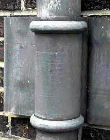 Figure 5: Collars: (a) Early ‘false’ collar and spigot joint formed simply by opening and closing the ends of the lower and upper pipes respectively, and applying cast astragals to the lower pipe, along with a band to create ears for fixing to the wall. (b) Typical plain collar fabricated separately as a wide cylinder, with cast astragals, and slipped over the lower pipe to form the collar to receive the spigot.
Photos: Peter T J Rumley 5a 5b
Figure 5: Collars: (a) Early ‘false’ collar and spigot joint formed simply by opening and closing the ends of the lower and upper pipes respectively, and applying cast astragals to the lower pipe, along with a band to create ears for fixing to the wall. (b) Typical plain collar fabricated separately as a wide cylinder, with cast astragals, and slipped over the lower pipe to form the collar to receive the spigot.
Photos: Peter T J Rumley 5a 5b
SPAB Plumbing Leadwork: Joints and Pipes9
4 References
1 The soldering process described is for forming lead-to-lead joints. When joining copper or brass to lead, the method varies. After the copper or brass is cleaned with wire wool, it is given a thin coating of solder (‘tinned’) to ensure good coverage and a strong joint. The pipe can go cold if need be. The lead is not tinned. The two pieces are located and heated with flux and solder
2 Moleskin is a densely woven cotton fabric with a soft pile on one side that resembles the fur of moles (but is not actually animal skin)
5 Other advice
5.1 Contacts
Where work to plumbing leadwork is being considered, the SPAB may be able to suggest suitable specialists, including contractors.
5.2 Further Reading
Davies, P (1898) Standard Practical Plumbing, London: E & F Spon Ltd
Lloyd, N (1929) Building Craftsmanship, Cambridge: Cambridge University Press
Martin, A (1929) The Modern Practical Plumber, London: Caxton Ltd
Molloy, E (1943) Lead Pipe Work, London: George Newnes Ltd
Rumley, P T J (2007) Conservation of Decorative Leadwork, SPAB Technical Pamphlet 17, London: SPAB
Slocombe, M (2017) The SPAB Approach to the Conservation and Repair of Old Buildings, London: Society for the Protection of Ancient Buildings
5.3 Other organisations
• Weald & Downland Living Museum www.wealddown.co.uk 01243 811363
The Worshipful Company of Plumbers has supported the creation of a Museum of Plumbing in Court Barn at the Weald & Downland Living Museum. There is an exhibition here that illustrates the traditional role of the plumber and plumbing skills. Nearby is a plumber’s workshop, c1925, that was moved from Newick, East Sussex and in which are displayed a wide variety of tools and equipment donated by many craftspeople

5.4 Health and safety
In most cases the use of lead in building does not create a significant hazard, although it is essential not to eat, drink or smoke in a place liable to be contaminated with lead and also to wash your hands, arms and face thoroughly at the end of each working session. When undertaking hot works in unventilated conditions, additional precautions must be followed.
Hot work is a serious fire hazard and a permit may be required to undertake this operation.
Plumbing Leadwork: Joints and Pipes
Figure 6: Bobbins used for truing bends in lead pipes. Photo: Douglas D Kent
SPAB
10
Heel
Bending spring

Throat
Lead pipe
Heel
Heel
7(a)
Wooden followers
Wooden bobbin
Wooden bobbin to fit bore of pipe Metal snatch weight moved back and forth
Throat
Drift to push or pull bobbin through
7(b)
Throat
Dummy
7(c)
Figure 7: Bending pipes: (a) Spring pipe bending. (b) Bobbin bending. (c) Bobbin, snatch weight and dummy bending.

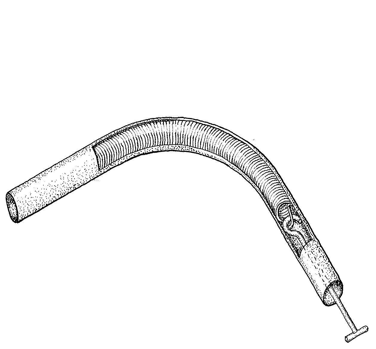
Illustrations: Nicola Westbury
Plumbing Leadwork: Joints and Pipes
SPAB
11
The content of this publication is offered in good faith, but neither the author nor the Society can accept responsibility arising from incorrect or incomplete information that may be included. The use of traditional materials may incur risks that are different from those associated with modern materials. Manufacturers’ and suppliers’ guidelines should always be observed. This document is intended as a contribution to a continuing debate and we welcome comments.
Written by Peter T J Rumley. The author is indebted to Douglas Kent (SPAB Technical and Research Director) and Tim Ratcliffe (Tim Ratcliffe Associates, architect and historic building and traditional material consultant) for their help with the preparation of this document. Edited by Kit Wedd. Grateful thanks to Judith Rodden for editorial advice. Produced by Catherine Peacock. The sources of illustrations are given adjacent to them together with any copyright where not belonging to the SPAB.
The Society for the Protection of Ancient Buildings (SPAB) believes old buildings have a future. From cottages to castles and from churches to cathedrals we are here to help buildings and the people who care for them.Through our unique training schemes, courses, advice and research we help people put our expertise into practice.
The Society for the Protection of Ancient Buildings (SPAB) believes old buildings have a future. From cottages to castles and from churches to cathedrals we are here to help buildings and the people who care for them. Through our unique training schemes, courses, advice and research we help people put our expertise into practice.
Founded by William Morris in 1877, the SPAB was established in response to the work of Victorian architects whose enthusiasm for harmful restoration caused irreparable damage. Today the SPAB encourages excellence in new design to enrich and complement the built historic environment. We train new generations of architectural professionals and building craftspeople to shape this landscape with sensitivity and skill, and we play a statutory role as adviser to local planning authorities. In our casework we campaign actively to protect old buildings at risk.
Today the SPAB encourages excellence in new repair and good design to enrich and complement the built historic environment. We train new generations of architectural professionals and building craftspeople to conserve this landscape with sensitivity and skill, and we play a statutory role adviser to local planning authorities. In our casework we campaign actively to protect old buildings at risk.
SPAB: hands on history. Join today to support our positive, practical approach to building conservation.
SPAB: hands on history. Join today to support our positive, practical approach to building conservation.

Published by the SPAB in April 2019
© SPAB 2019 Edn 2 Rev 0
SPAB ref T5301R www.spab.org.uk
ISBN 978-1-898856-43-6
The Society for the Protection of Ancient Buildings 37 Spital Square, London E1 6DY Tel 020 7377 1644 info@spab.org.uk www.spab.org.uk
A charitable company limited by guarantee registered in England and Wales Company No 5743962 Charity No 111 3753 VAT No 577 4276 02
Conservation of Decorative Leadwork

SPAB Technical Advice Note
Peter T J Rumley MA, DPhil, MA, FSA, MCIfA
The Society for the Protection of Ancient Buildings
37 Spital Square London, E1 6DY 020 7377 1644
info@spab.org.uk www.spab.org.uk

Contents
This Technical Advice Note describes principles and practices used in the conservation of decorative architectural leadwork.
Ornate leadwork is an overlooked aspect of building conservation. Although historic designs demonstrate the skill and artistry of early plumbers, metalworking techniques such as piercing and wrought work are no longer readily associated with the craft. It is also forgotten that leadwork was often brightly tinned, gilded or painted.
This lack of awareness is compounded by the construction industry’s neglect of the plumbing techniques essential to decorative leadwork, which is different from modern lead sheet work and requires a wider range of skills.
Much original leadwork has already been lost, and poor repairs threaten Britain’s surviving stock of historic decorative lead items, so every effort must be made to save what remains.
1 Introduction
2 History
3 Fabrication
4 Identification of defects
5 Conservation
6 Surface decoration
7 References
advice
Cover image: Seventeenth-century decorative rainwater head at Hatfield House, Hertfordshire.
Photo: Peter T J Rumley
3
SPAB Conservation of Decorative Leadwork2
.......................
....................... 4
....................... 8
....................... 12
....................... 14
....................... 18
....................... 19 8 Other
....................... 19
1 Introduction
The chief characteristics of lead are its weight, colour, durability and malleability. These properties, and the ease with which the metal can be manipulated, cast, decorated and jointed, make it suitable for a wide variety of architectural uses.

Lead’s resistance to water makes it ideal for weatherings and conveying rainwater: the runoff from lead-covered roofs can be carried via lead gutters and downpipes into cisterns and pipework made of the same material (see figures 1 and 2).
Because lead (see figure 3) is highly ductile and lends itself to finely detailed ornamentation, it offers scope for decoration to be incorporated into rainwater goods and into other architectural items, ranging from fonts to glazing cames and fanlights. Its ability to withstand the effects of weather also makes it suitable for garden ornaments and other, purely decorative, uses.

There already exist some excellent technical publications on underside lead corrosion, lead sheet roofing and the repair and conservation of lead sculpture. The SPAB Technical Advice Note on Plumbing Leadwork: Joints and Pipes, covers non-ornamental plumbing leadwork skills. The advice below is intended to complement existing publications by providing an introduction to decorative leadwork and some guidelines on techniques, principles and practice. Although the skills for repairing and conserving decorative leadwork may be beyond the scope of most readers, the Advice Note aims to help enable owners of old buildings understand the complexity of the subject before employing a skilled craftsperson; and also to give the plumbing leadworker an appreciation of the approaches that should be employed in conservation and repair.
Technical terms used in this guidance are defined in our online glossary.1
Figure 3: Symbol for lead. The alchemists used the same symbol for lead and for Saturn – perhaps because Saturn is the father of the gods and lead one of the oldest metals. Illustration: SPAB
Figure 1: Decorative rainwater head of 1635 at St John’s College, Oxford.
Photo: Peter T J Rumley
Figure 2: Early 19th-century print (anon) showing plumbers undertaking sheet leadwork. Note the soldering iron in the foreground. Photo: Philip Venning
SPAB Conservation of Decorative Leadwork3
2 History
2.1 Uses
Lead has been mined and smelted since antiquity. Under the Romans, welding and casting techniques were used to construct lead water pipes in several standard lengths and diameters, as laid down by Sextus Julius Frontinus, Water Commissioner of the City of Rome, in AD 97. Archaeological excavations have shown that Romano-British builders made lead sheets to form water tanks, some of which bore inscriptions, string designs or monograms.
The Worshipful Company of Plumbers received its Ordinance in 1365 and was granted a royal charter by James I in 1611. In the medieval period, lead was used extensively, both for utilitarian purposes and, to great decorative effect, on high-status structures such as cathedrals, churches, monasteries, castles and royal palaces. In 12th-century Britain, beautiful baptismal fonts were made of lead; around 30 of these survive, their moulded designs still clearly discernible. At All Saints’ Church in Shipdham, Norfolk, the medieval plumbers dressed lead sheet over the distinctive decorative wooden flèche for weather protection (see figure 4). Church roofs were also adorned with crests, weathervanes or figures of saints made from lead (see figure 5).


The stonework of some Norman castles was decoratively capped with lead sheet. In the 13th century, Henry III applied lead to the roofs and battlements at Dover Castle in Kent, and from the 14th century, all manner of towers and turrets in England and Scotland were clad with lead. Scottish castles maintained their characteristic ‘tiled’ leaden roofs until the 19th century. Lead helped preserve a string of castles belonging to Henry VIII, of which St Mawes, Cornwall remains the perfect example. George III had the gun platforms on his east and south coast Martello towers covered with lead.
The metal was also used extensively in grand country houses and their gardens. After the dissolution of the monasteries in the 1530s-40s, church and cloister roofs were stripped of their lead, which was then recast and used during the conversion of ecclesiastical buildings into houses, among them Lacock Abbey in Wiltshire, Leez Priory, Essex and Mottisford Abbey, Hampshire. Lead from the same source was also reused for ornamental urns, fountains, cisterns and statues.
Figure 4: Typical example of a country church flèche at All Saints’, Shipdham, Norfolk. Lead was dressed over a complex timber frame to provide a distinctive silhouette to the skyline. Photo: Peter T J Rumley
Figure 5: Lead angel on guttering at the Church of St Michael the Archangel, Framlingham, Suffolk.
Photo: Simon Barber /SPAB
SPAB Conservation of Decorative Leadwork4
On medieval cathedrals, churches and important secular buildings, rainwater was usually drained from the roof through carved stone gargoyles. However, as building fashions changed, there arose a distinctly British tradition of using lead for decorative rainwater heads. There is a reference to lead downpipes at the Tower of London in 1241 and the oldest surviving examples date from the mid-16th century. Towards the end of the 15th century, as red brick was becoming fashionable for fine houses in England and Wales, lead sheet was used to make stylish heads to carry rainwater from roofs into downpipes; in the 17th and 18th centuries, the water was fed via downpipes into ornate lead cisterns at lower levels (see figure 6).
In the 17th century, plumbers developed their decorative skills to the full. Haddon Hall, Derbyshire, built with the leadmining wealth of the Vernon and Manners families, has some of the earliest surviving decorative rainwater heads. The expansion of the house through successive generations has provided it with the finest historical series of decorative rainwater heads (c1580-1670) in England. The

early examples incorporate repoussé work and bartizans (see figure 7); the later have elaborate and delicate pierced tracery with dentil courses, pendants and cast enrichments.

When Thomas Sackville enlarged his house, Knole in Kent, in the early 17th century, he beautified the severe exterior with richly delicate rainwater heads of pierced work interlaced with crests, dates, arms, initials and complex tinned patterns of chequers, chevrons, strapwork and stars. This is the finest group of rainwater heads of a single period on a country house: not only are the bartizans pierced, but solid cast pendants provide another dimension on sunny days, by throwing interesting, crisp shadows (see figure 8).
 Figure 6: Sand-cast lead cistern of 1774 embellished with strapwork and motifs. Photo: Douglas D Kent
Hall, Derbyshire. Photo: Peter T J Rumley
Figure 8: Tinning of stars, chequerwork, strapwork and, far right, fleur-de-lis on a rainwater head that incorporates eight battlemented bartizans, the third from the right pierced. The date, initials, crest and leopard rampant are cast and soldered. Stone Court, Knole, Kent, 1605.
Photo: Peter T J Rumley
Figure 6: Sand-cast lead cistern of 1774 embellished with strapwork and motifs. Photo: Douglas D Kent
Hall, Derbyshire. Photo: Peter T J Rumley
Figure 8: Tinning of stars, chequerwork, strapwork and, far right, fleur-de-lis on a rainwater head that incorporates eight battlemented bartizans, the third from the right pierced. The date, initials, crest and leopard rampant are cast and soldered. Stone Court, Knole, Kent, 1605.
Photo: Peter T J Rumley
SPAB Conservation of Decorative Leadwork5
In Britain, lead statutes were cast as early as the 15th century but the technique was used most prolifically between the 17th and 19th centuries. Significant decorative leadwork was used at Hatfield, Herfordshire – not only on the house but in Robert Cecil’s fantastic lost water garden. The centrepiece of the garden was a lead statue of Neptune. It took 1 100 kg of plaster to make the mould and 140 kg of ‘solder’ for the casting, which was executed by the Dutchman, Garret Christmas. Cecil’s decorator, Rowland Buckett, painted the statue to resemble copper and he may well have had something to do with the decoration of Hatfield’s rainwater heads (see front cover).
William Peele, plumber, was engaged to cast lead snakes, fishes and leaves, to be painted and scattered around the fountain.

The late 17th-century resurgence of the founder’s craft was led by artists such as John van Nost, who came to England during the reign of William III (1689-1702) and set up a foundry in Piccadilly, London. At Canons Ashby, Northamptonshire, there is a unique baroque cartouche made of lead above the door entrance of Green Court. It was commissioned by Edward Dryden in 1710 and attributed to van Nost, who may well have completed the elaborate cast rainwater heads and downpipes. On the south front are two sets of rainwater heads and downpipes, also dated 1710, which display a floral motif reminiscent of tulip leaves at each pipe socket. Nost’s business was carried on into the 18th century by the sculptors John Cheere and Sir Henry Cheere.
The casting of lead sculpture by the lost-wax technique was, on the whole, the province of the artist/sculptor. The secrets of the technique were published in French, which few plumbers could read.2 The skills of the leadworker and the sculptor were passed on only to those who were apprenticed in a protectionist trade society (see figure 9). Plumbers, on the whole, kept to simple open sand or metal chill moulds to form their enrichments. Manufacturers in the 19th century, such as Henry Hope of Birmingham, developed cast iron closed moulds to produce an array of intricate lead rainwater heads, downpipes, gutters and collars.
The revival of traditional building materials and methods prompted by the practical example of Gothic Revival architects and by the writings of John Ruskin and William Morris, led to a resurgence in decorative architectural leadwork, which was used to complement the solid, impressive character of Arts and Crafts buildings in the late 19th and early 20th centuries.
2.2 Colour
The attractive dull, silvery-grey surface finish of ornamental architectural leadwork is so familiar that few people realise that originally, the leadwork may well have had a highly colourful surface treatment. Surface decoration would have taken the form of tinning, gilding, painting and, sometimes, artificial patination, mastic inlays, etching and leadburning (see figure 10).
In medieval England and Europe, numerous ecclesiastical and important secular buildings had whole roofs, girouettes, flèches, ogee domes, lanterns, pennons and spires gilded, painted or tinned to provide a dazzling display of chevrons or chequered polychrome patterns. The tradition persisted beyond the medieval period: Félibien, writing in 1676, informs us that plumbers wishing to tin whole sheets of lead use a tinning furnace of hot charcoal, ‘on each side of which a man stands holding up and heating the sheets of lead. Leaves of tin foil are laid over these, and as the sheets get hot and the tin melts the tinning accomplished by rubbing and spreading it over the surface with tallow and resin.’3
At Windsor Castle in Berkshire, a colossal fountain, mostly in led, was erected in the centre of the Great Upper Court for Mary I in 1555, under the control of John Puncherdown, Sergeant Plumber. Carpenters made wooden patterns for the moulds used in the plumbery to make the royal coat of arms and the great Beasts Royal. The latter included an eagle, a
Figure 9: Engraving showing a plumber’s workshop of 1676 with the furnace, sand bed and strickle – essentially the same as those still used in the manufacture of sand-cast sheet lead (Félibien, 1676)
SPAB Conservation of Decorative Leadwork6
lion, an antelope, a greyhound and a griffin, all some 2 m tall, and a dragon 3.5 m long at the base, which spouted water to a height of 4 m. John Nicholas Lyzard, Sergeant Painter, decorated the royal coat of arms, first priming the heraldic beasts and painting them with red lead, then gilding them.
John Stow’s A Survey of London (1598) described the bell tower leadwork of the priory church of St John of Jerusalem, Clerkenwell, as ‘a most curious piece of workmanship, graven, gilt, and enamelled, to the great beautifying of the city, and passing all other that I have seen.’⁴ Stow was also impressed by the appearance of Goldsmith’s Row:
‘It containeth in number ten fair dwellinghouses and fourteen shops, all in one frame, uniformly built four stories [sic] high, beautified towards the street with the Goldsmiths’ arms and the likeness of woodmen, in memory of his name [Thomas Wood, goldsmith], riding on monstrous beasts, all which is cast in lead, richly painted over and gilt.’⁵
London’s lead-enriched skyline must have looked magnificent above the narrow, bustling, stench-ridden streets. Royal palaces, including Hampton Court and the Nonsuch Palace, were also abundantly decorated with lead.

Oil gilding of features such as dates, crests and owners’ initials on lead rainwater heads and cisterns was popular in England from the 17th century. Historically, such decorative painting and gilding work was allocated to members of trade guilds, such as the Painter-Stainers Company. The great baroque lead cartouche of the Dryden arms, 1710, over the Green Court Hall door at Canons Ashby was at one time painted in bright heraldic colours, but more recently only the lead sculpture in Green Court has been painted a stone colour (see figure 11).


In contrast, the rainwater heads and pipes in Canterbury Quadrangle, St John’s College, Oxford, have been gilded and painted many times since 1635 and the fresh, bright colours enhance these outstanding examples of the plumber’s decorative craft, as well as conserving the original intention to the benefit of the architectural whole (see figure 12).
 Figure 10: Colourful surface treatment: (a) Gilded rainwater head, Upnor Castle, Kent, 1718. (b) Painted rainwater head, Tilbury Fort, Essex, 1719. (c) Gilded and painted pipe collar, St John’s College, Oxford, 1635. (d) Tinning of circles and chevrons, Knole, 1605.
Photos: Peter T J Rumley
10(a) 10(b) 10(d)10(c)
Figure 10: Colourful surface treatment: (a) Gilded rainwater head, Upnor Castle, Kent, 1718. (b) Painted rainwater head, Tilbury Fort, Essex, 1719. (c) Gilded and painted pipe collar, St John’s College, Oxford, 1635. (d) Tinning of circles and chevrons, Knole, 1605.
Photos: Peter T J Rumley
10(a) 10(b) 10(d)10(c)
SPAB Conservation of Decorative Leadwork7
3 Fabrication
Two broad categories of work form the basis of all historic decorative leadwork. The first is the skilful fabrication of sheet lead using tools, and techniques that include repoussé work, carving and piercing, and wrought work. The second category is the casting of molten lead in moulds, either to embellish sheet lead or make individual ornaments to be applied separately. As well as these specialist decorative techniques, plumbing leadwork skills such as pipe fabrication and joint solder wiping are required (for further details see Plumbing Leadwork: Joints and Pipes. Finished pieces may be further embellished with tinning, gilding, painting and other forms of surface decoration (see section 6).


3.1 Sand-cast lead sheet: plain
Sand-cast lead has been used since antiquity. In all periods, it was customary for plumbers to cast their own lead sheet in the workshop or on site, by running molten lead over a bed of sand (see figure 13). At Exeter Cathedral, a 19th-century lead furnace remains in the roof of the south tower (see figure 14). Rolled lead – a cheaper lead produced in a rolling mill and supplied in uniformly even sheets – became available towards the end of the 17th century.
Items such as decorative rainwater heads can be fabricated from pieces cut from lead sheet. For instance, to fabricate a half-round rainwater head (see figure 15), a piece of wood has to be turned to the required pattern and then cut in half – a skill in itself. The wooden block is then fixed to the workbench and a piece of lead
SPAB Conservation of Decorative Leadwork
Figure 12: Rainwater heads at St John’s College, Oxford, 1635: (a) With gilded unicorn cut from sheet lead and set in front to provide depth and shadows. (b) Gilded and painted. Photos: Peter T J Rumley
12(a)
12(b)
Figure 11: Cast lead statue painted to imitate stone, Canons Ashby, Northamptonshire, 1710. Photo: Peter T J Rumley
8
sheet is gently dressed over it, using a variety of wooden dressers.
Another method of making up the front of a rainwater head is to use several pieces of sheet lead (see figure 16), which are soldered, wiped soldered or leadburnt together. A flat back is then attached, along with ‘ears’ for fixing to the wall. Various specialised decorative techniques (explained in sections 3.3 and 3.4) can be used to form more complex embellishments, according to the imagination and inventiveness of individual plumbers.


3.2 Sand-cast lead sheet: decorative Decorative lead sheet is cast in the same way as plain lead sheet, except that moulds or patterns are pressed into the sand to provide decoration to the underside of the lead (which will, of course, be used on the face of the finished

 of
Figure 13: Sand-casting of lead sheet.
Photo: Norman & Underwood Group Ltd
Figure 14: Nineteenth-century lead furnace (disused) at Exeter Cathedral. Photo: Peter T J Rumley
Figure 15: Formation of a decorative rainwater head: (a) Half-round wooden block over which lead is dressed. (b) Half-round 18thcentury rainwater head having been dressed over wooden block at 16 Watling Street, Canterbury, Kent. Photos: Peter T J Rumley
Figure 16: Combination of sheet lead sections shaped over wooden block, soldered and wiped soldered with pierced work added. Note the shadows cast by the solid pendants. Knole, Kent, 1605.
Photo: Peter T J Rumley
15(a) 15(b)
of
Figure 13: Sand-casting of lead sheet.
Photo: Norman & Underwood Group Ltd
Figure 14: Nineteenth-century lead furnace (disused) at Exeter Cathedral. Photo: Peter T J Rumley
Figure 15: Formation of a decorative rainwater head: (a) Half-round wooden block over which lead is dressed. (b) Half-round 18thcentury rainwater head having been dressed over wooden block at 16 Watling Street, Canterbury, Kent. Photos: Peter T J Rumley
Figure 16: Combination of sheet lead sections shaped over wooden block, soldered and wiped soldered with pierced work added. Note the shadows cast by the solid pendants. Knole, Kent, 1605.
Photo: Peter T J Rumley
15(a) 15(b)
SPAB Conservation
Decorative Leadwork9
items). Leadworkers often make their own moulds or patterns. The deeper the mould, the more sand is required and the deeper the bed. Equally, more lead is required for the crucible and the completed piece is correspondingly heavier.
A great variety of decorative objects, including downpipes and gutters, may be formed in this way. Normally, decorative downpipes were cast in 2 m lengths (see figure 17), in a sand bed that was reduced from the normal 3-3.5 m length. Three or four designs may be cast in one go and the sections separated later. After casting,
each lead strip may be folded around a square or cylindrical mandrel to form the pipe.
Strapwork decoration is formed using strips of cast lead, which can easily be bent into curves and pressed into the sand to provide the design.
The great decorative lead cisterns of the 17th and 18th centuries were cast in this way. With cisterns, the shape of the casting bed may well have taken the cruciform shape of an opened-out cardboard box, the sides being folded and wiped jointed after the lead had set or ‘frozen’.
On large cisterns, strengthening stays were soldered across the interior to help support the sides.
3.3 Decorative techniques
In addition to casting (see sections 3.2 and 3.4) and surface decoration (see section 6), the following techniques were used to add decorative interest:
• Repoussé work. This term is often used in the narrow sense of hammering metal into relief from the reverse side, but is taken here in a broader sense that includes the simple dressing of lead over a mould to form shapes, such as faces.
• Carving and pierced work. Lead may be carved with gouges. The intricate pierced work used to form a valance or bartizan tracery is achieved by using sharp chisels, punches and knives to cut out patterns from sheet lead. The sheet lead is worked whilst on a soft block of lead or wood. Keeping the tools wet assists the action. At Knole, Hatfield House, Haddon Hall, Canons Ashby and St John’s College, Oxford, it is possible to see not only surface decoration but also sumptuous forms of ‘filigree’ pierced work, which cast elegant, crisp shadows in bright sunlight (see figure 18).
• Leadburning. This form of surface decoration is the most recent, having been introduced in the early 20th century, following the development of the oxyacetylene torch. Leadburning may be used not only to weld two sections of sheet lead, but also to form bead patterns of lead across the surface by applying a number of loadings with excess lead from the lead filler stick. Depending on how the oxyacetylene torch is held, a bead or herringbone pattern may be achieved by skilful manipulation of the molten pool of lead.
• Wiped soldered decoration. When plastic solder is being applied to large soil or vent pipes and, occasionally, rainwater downpipes, it may be fluted with the finger or a shaped tool to provide some decorative interest on an otherwise plain joint. Examples may be seen at Upnor Castle in Kent, Lanhydrock in Cornwall and Firle Place, East Sussex. This form of decoration is characteristic of 18th-century pipework.

• Wrought work. This is the beating of cast sheet into highly decorative shapes for finials, crestings etc (see figure 19). Medieval plumbers worked their lead to perfection, their skill equalling that of the goldsmith working precious metal.
 Figure 17: Sand-cast downpipe with a grape and vine motif (Weaver, 2002).
Photo: Courtesy of Donhead Publishing Ltd
Figure 18: Pierced work with tinning on bartizans, Hatfield House, Hertfordshire, 1610. Photo: Peter T J Rumley
Figure 17: Sand-cast downpipe with a grape and vine motif (Weaver, 2002).
Photo: Courtesy of Donhead Publishing Ltd
Figure 18: Pierced work with tinning on bartizans, Hatfield House, Hertfordshire, 1610. Photo: Peter T J Rumley
SPAB Conservation of Decorative Leadwork10
3.4
Applied lead castings
Beside the casting of molten lead to produce ornamental lead sheet as described in section 3.2, individual enrichments for soldering or leadburning can be made by the following methods:

• Open sand moulds. A pattern of wood or plaster is pressed into an open box or tray of fine, damp sand and lifted away, leaving a void of the required shape. Molten lead is poured into this mould, and when the metal has cooled and hardened, the casting is removed and the excess sand is brushed off back into the box, where it can be used again to make a fresh mould. This mould is used to make a variety of decorative castings, including crests, dates, initials, rope twists, battlements, cornices, downpipe collars or astragals.
• Two-piece moulds. A two-piece closed mould gives a solid lead casting within a sand box, which can be separated (see figure 20). The pattern may also be in two halves depending on the complexity of the design. One half of the pattern is placed on a flat surface; one half of the wooden box is placed around it. This is then rammed with casting sand (naturally bonded or oil-based) and the box is turned over. The other half of the pattern is located precisely on top of the half pattern remaining in the sand by register pins. The whole is then dusted with parting sand before placing the remaining half of the moulding box with its register pins in line. This is then rammed with moulding sand. The two boxes are parted, the pattern removed and two pouring holes, or ‘gates’, are made by pushing a sharp dowel through the sand: one gate is for pouring the molten lead into the mould and the other acts as an air vent.
• Chill moulds. Plumbers regularly used these when crafting sections for decorative rainwater heads. They are simple, open cast iron moulds, about 500 mm long, into which molten lead is poured to form astragals or battlements. When poured into the cold metal mould, the lead ‘chills’ and hardens rapidly. Unlike a sand mould, which has to be made afresh after each use, a chill mould can be used repeatedly.
• Closed cast iron moulds. Victorian and Edwardian foundries used these moulds to mass-produce decorative lead rainwater heads and other associated accessories, such as downpipe collars and cast ears.
Figure 19: Design for wrought leadwork in the shape of foliage and a rose bud. Illustration: Nicola Westbury

• Waste moulds. These are used for one-off castings, after which they are destroyed. In the past such moulds were made of plaster; today they are more likely to be made of heat-resistant vinyl.
• Lost-wax casting. This technique, also known as cire perdu or investment casting, produces a one-off piece, for the mould is destroyed to release the casting.
Figure 20: Casting molten lead in a two-piece mould. Photo: Douglas D Kent
SPAB Conservation of Decorative Leadwork11
Initially a solid model is made in wax. Plaster casts are then made from sections of this model; these are known as ‘case moulds’, which can be reused. These plaster moulds are then fitted together before hot wax is poured into the cavity they enclose; the superfluous wax is poured out, leaving a thin wax lining on the interior surface of the moulds.
The case moulds are removed, revealing various pieces formed in hollow wax. These separate pieces are then joined to create a copy of the original model, but in hollow, not solid, wax. A hole is cut into this hollow wax model, and sand and plaster are poured into it to form a solid core. Wax rods are fixed in appropriate places on the model, to allow molten lead to feed into it and gases to escape; a wax funnel is also created. Thin metal pins (chaplets) are pushed through the wax model into the core. The entire block is encased in fine plaster, then placed in a kiln and the heated wax is driven out. Molten lead is then funnelled into the thin cavity left by the wax, with the metal pins holding the core in place. The plaster is broken off and the rods, now formed of metal, are cut away, the pins removed and the model cleaned.
Sir Henry Cheere (1703-1787) used this method to cast his hollow sculptures. In this case, large sections would have been cast separately and then soldered together.
4 Identification of defects
Lead is a very durable material, and many architectural elements continue to function perfectly well as originally designed, three or four centuries after they were first installed. In certain conditions, however, decorative leadwork can develop defects.
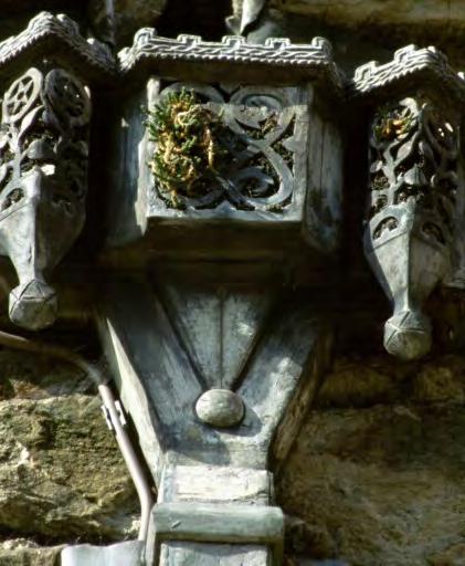
4.1 Corrosion
Although lead is highly resistant to corrosion, it is not immune to it. The metal is amphoteric: that is, it can be affected by both acids and alkalis, depending on interactions with other chemicals. Corrosion occurs at various rates in different environmental conditions. For example, lead reacts with water, oxygen and carbon dioxide in the air to form lead carbonate, which in itself forms a stable, protective white surface film. However, where certain acids, such as acetic, formic or nitric acid are present, corrosion may take place.
The principal environments in which lead is liable to corrode, albeit slowly, are:
• Oak-shingled roofs. Rainwater run-off is certain to contain tannic acid absorbed from the timber.
• Lichen- and moss-covered roofs. Organic acids from the plant life may leach into rainwater run-off (see figure 21).
• Timber supports. The use of modern laminates or timber such as oak as bearers to support cisterns, gutters or rainwater heads should be avoided: these materials contain organic acids that will corrode lead.
• Insects. A blocked rainwater head, pipe or gutter that contains, say, a colony of ants, can produce enough formic acid to attack the lead, especially if the host organic material is peat-based and enriched with bird droppings.
• Industrial environments. The vapours emitted from breweries and tanneries may be corrosive.
• Masonry cleaning agents. Hydrochloric and hydrofluoric acids are normal building cleaning agents, which will corrode unprotected lead.
• Fluxes. Only mild, non-corrosive fluxes such as tallow or rosin should be used when soldering or wiping lead.
of Decorative
Figure 21: Moss and other organic matter lodged in pierced bartizans, prior to cleaning. Knole, Kent.
Photo: Peter T J Rumley
SPAB Conservation
Leadwork12
• Lime and cement. Alkalis have a moderately corrosive effect, depending on moisture, aeration, temperature and concentration. Calcium hydroxide solutions, perhaps from water that has been in contact with fresh Portland cement, are damaging.

• Storage. If any decorative leadwork is going to be stored for long periods, it is important to cushion and support the pieces on crumpled, acid-free paper in dry conditions. Plastic wrappings should be avoided, as they may trap moisture, creating corrosive micro-environments.

There appears to have been an unexplained increase recently in brown-red surface discoloration on leadwork. This phenomenon is not believed to shorten the life of lead.⁶ It is possible to remove the staining chemically.
4.2 Thermal stress failure
Lead has a high linear coefficient of thermal expansion (approximately three times that of steel) which may cause it to buckle and crack. Items such as rainwater heads, pipes, gutters and cisterns are less likely than lead sheet roofing to suffer from thermal fatigue because they are usually fabricated from smaller sheets of heavier-gauge lead.
The solder used for wiping joints is an alloy of lead and tin and exhibits different thermal characteristics from the body of lead being joined; but it is wrong to imagine that this causes failure. The splitting or tearing of the lead that can appear next to a wiped
joint is normally a result of lead corrosion or mishandling; it is particularly important to move large, heavy items with care.
4.3 Frost damage
Rainwater systems should be checked for blockages and cleared as part of normal maintenance routines. If water is trapped in a pipe, gutter or cistern in frosty conditions it will turn to ice. As it freezes, it expands and causes the lead to split. For this reason, the joints in downpipes were not usually caulked, allowing water to escape at the open spigot joints to indicate a blockage in the next section of pipe below. Continuous lengths of soil pipe were joined by solder wiping; they tend to fail on bends, and rarely at the wiped joints (see figure 22).
4.4 Insufficient support
Rainwater heads and pipes were usually fixed into place by wrought iron pipe nails driven through purpose-made lead ears into wooden blocks built into the brick or stonework – or, worse, driven into the mortar joints. The lead band was cut long enough so that after the nails had been hammered into the walls the ends could be folded back over their heads. The plumber in the workshop normally cast these ears, or they could be purchased from suppliers. Ears came in all shapes and sizes and were soldered or leadburnt onto the pipe at regular intervals to suit the work in hand.
Figure 23: Torn lead cornice of rainwater head, prior to repair. Tilbury Fort, Essex. Photo: Peter T J Rumley
Figure 22: Common failure of a lead soil pipe, prior to repair. Ightham Mote, Kent. Photo: Peter T J Rumley
SPAB Conservation of Decorative Leadwork13
The iron nails invariably become corroded, and the wooden block may also rot, so that eventually, only the downpipe supports the rainwater head. In time, the downpipe begins to buckle under its own weight and becomes deformed.
The deterioration of internal wrought iron armatures or solid cores in cast lead components can also lead to deformation. Cast ornaments that have simply been soldered onto the front and not also pinned through to the back, may become detached.
4.5 Failure of surface decoration
Tinning is the most common of all the surface decorative treatments applied to leadwork. It is rare to find painted and gilded rainwater heads and pipes, and all such examples should be treated with great care:
• Tinning. This treatment rarely fails. Any peeling of the surface tinning that has occurred will be due to poor workmanship –failure to clean the lead surface or the use of insufficient flux.
• Gilding. The action of rain, frost and heat is the main cause of gilding degradation.
• Painting. Weather also erodes paint finishes, which simply wear away over time.
4.6 Vandalism and theft
The theft of lead from isolated churches and other buildings has long been a serious threat to historic decorative leadwork stock. Rainwater heads, pipes and roof sheet may be stolen for their scrap value, whilst urns and garden sculptures made of lead are also vulnerable. Prudent owners now ensure that lead garden ornaments are protected by alarms and other security measures.
In extreme circumstances, where there is genuine, serous risk to historic decorative leadwork, consideration may be given to moving an item into safekeeping for a time. This should only be considered as a last resort. Any leadwork removed for this reason should be handled and stored with care (see section 5.1).
4.7 Other defects
Mechanical damage may be caused by ladders being rested against rainwater heads and gutters (see figure 23), mishandling or even by heavy birds landing on delicate tracery. Unprotected, pipes at low level are also vulnerable to knocks from passers-by.


5 Conservation
The basic principle of good architectural conservation is to preserve as much of the original fabric as possible by undertaking only work that is essential to a building’s survival. Regular preventative maintenance is the most practical and economical form of conservation, and will reduce (or even obviate) the need for repairs later.
Where fabric has deteriorated, effective and honest repair should be the first consideration. Replacement is the last resort. Many lead rainwater heads and downpipes have been unnecessarily replaced with plastic or cast iron substitutes (see figure 24). Even the smallest lead strainer placed over a lead box gutter outlet, unseen behind a parapet, should be conserved in situ. Similarly, just because a decorative lead soil pipe finial is hidden is no reason to replace it, since in doing so, a valuable historic element is lost.
Figure 24: Avoidable loss of a rainwater head: (a) Eighteenth-century original. (b) Inappropriate replacement. Photos: Douglas Kent
24(a)
SPAB Conservation of Decorative Leadwork14
24(b)
5.1 Preliminaries
It is not unusual for the repair of historic decorative leadwork to be carried out as part of a larger building conservation contract where statutory consent has been granted.
Before survey or repair work is begun, a risk assessment may have to be completed and approved. Access to leadwork at high level is gained via scaffolding, which affords a safe way to carry out a preliminary survey and any subsequent handling of lead items.
If an item is to be removed from site for cleaning, repair or decoration, it should first be photographed in situ and carefully labelled (see section 5.2). Items such as rainwater heads can be extremely heavy, and the method of removal, handling and transportation should be planned in advance.
Delicate and fragile tracery or enrichments may become damaged when moved, so they should be protected by being placed in a rigid wooden box and cushioned with bubble wrap and crumpled, acid-free paper. Very heavy pieces may require a metal cradle to be specially made, and perhaps the use of a crane.
5.2 Recording
It is good practice to record the condition and appearance of decorative leadwork before commencing repairs. Photographs are satisfactory in some cases, but a written survey or drawings may also be required. By providing information about an item’s design and history, location, construction, decoration, and method of fixing, the leadwork survey will be a meaningful aid to repair and conservation:
The record should comprise a:
• Location plan.
• Unique reference number (for example, the first downpipe on the north-east elevation of Hatfield House might be identified as: HHNEE1 rainwater head/pipe 1/pipe 2/pipe 3/pipe 4/pipe shoe).
• Drawing.
• Set of photographs.
• Historical summary.
• Description of the item, its condition, method of fixing and any surface decoration.
• Conservation and repair summary.
All records should be kept on site as a permanent archive to which reference may be made.
5.3 Paint analysis
Even where decorative finishes appear to have been completely lost, traces of paint, gilding and coloured mastics may be discovered in crevices and folds. This valuable evidence of the original decorative scheme should be noted in the written record. Samples may be submitted to a specialist for detailed paint analysis to determine the composition of the paint, which will assist understanding of the original decoration.
5.4 Cleaning
Painted and gilded surfaces of decorative leadwork that are coated with dirt may be gently cleaned with a soft cloth rinsed in water containing a few drops of washing-up liquid per bucket of water. Use warm water for painted areas and cold water on gilding. A soft toothbrush may be used for awkward corners and pierced work. If more stringent methods are required to remove heavily polluted buildups then it is important to remember that aggressive cleaning agents are likely to damage painted decoration.
For the removal of paint, a proprietary poultice paint stripper may be used, particularly on details such as bartizans, and applied dates, heraldic devices or ciphers that may embellish rainwater heads on complicated pieces. Follow the manufacturer’s instructions carefully.
Do not under any circumstances use a blowtorch to remove paint that has been used to decorate leadwork. The fumes given off by hot lead are highly toxic, and may paralyse the operative if inhaled. Heat can distort the piece or, more drastically cause the soldered or wiped joints to run, and the piece to disintegrate.
Areas of leadwork that are neither painted nor gilded may become encrusted with sulfates. In such cases, the piece may be scrubbed hard with a stiff brush and hot water containing detergents. The water should be changed frequently.
The use of microblasting is potentially hazardous unless a fume cupboard is used, or the operative is completely covered by protective clothing incorporating a separate oxygen supply.
SPAB Conservation of Decorative Leadwork15
5.5 Repairs
A thorough understanding of old buildings and their components is a prerequisite for successful repair work. Considerable damage has been inflicted on delicate and decorative leadwork through ‘repairs’ carried out by operatives who lacked sufficient understanding of historic fabrication and jointing methods, or were unfamiliar with historic decorative surface techniques.
Lead lends itself well to repair, because it is possible to cut out a damaged section and leadburn in a new section, and clean the seam of the joints to produce an invisible mend. The metal can equally well be soldered or solder wiped; these techniques are particularly useful for repairing small pinholes and splits. Fillers such as epoxy resins, or any other foreign material, should not be used to repair such defects in leadwork.
Sometimes a solution can be devised that avoids cutting out. For example, a new lead reservoir might be fabricated in Code 4 sheet lead and fixed inside the old reservoir of a rainwater head in poor condition, taking care to provide further reinforcement stays and remembering that further weight is added.
Occasionally, a case exists for easing distorted leadwork back into shape, for example, when a piece no longer functions as intended (obstructing water flow etc). However, if the leadwork is functioning and fixed properly and all that is wrong is some deformation to one side, then it is best left well alone. Misshapen rainwater heads and pipes do have a charm of their own and to reshape them so that they look like new detracts from this appeal. It can
be advisable to provide additional protection – for instance, a metal sleeve or grille to shield a downpipe at low level in a location where it is vulnerable to knocks (see figure 25). An alternative method is to split the back of the downpipe and insert a stainless steel lining before re-making the joint.

Stainless steel may also be used to replace wrought iron armatures where these have become corroded, leading to the deformation of a cast lead component. Similarly, when a downpipe or rainwater head is being repaired there is an opportunity to consider the method of fixing and replace corroded wrought iron pipe nails with stainless steel bolts set in plastic plugs.
When re-making joints, it is important to copy the original jointing methods (leadburnt, soldered or wiped soldered) and not to ‘improve’ upon them, as to do so is to change the fundamental nature of the historic piece. (For further details see Plumbing Leadwork: Joints and Pipes,. Take care not to follow inappropriate examples set by earlier repair work. There are many instances where unskilled individuals have tried to replace soldered joints by leadburning (welding) inside restricted rainwater head reservoirs, leaving unsightly globules of molten led, which hamper the flow of water and cause debris to accumulate. Smooth wiped joints would have been easier to perform in such cases, and would not have impeded water flow.
Hot work is a serious fire hazard and a permit may be required to undertake this operation (see section 8.4).
5.6 Replacement
Replacement should not be undertaken simply because decoration is showing signs of wear or a piece is no longer perfectly shaped. Figure 26 shows unusual decorative lead items that give additional interest to buildings but could so easily be replaced with bland modern equivalents or substitute materials. Replacing original material should be done only when it can be fully justified; sometimes, for example, the replacement of lead sheet is unavoidable because it is seriously degraded with microcracks that are impossible to repair.
Any replacement should be on a like-for-like basis. Where lead sheet is replaced, sand-cast lead should be used for all conservation work unless the original piece was constructed with the milled variety. Sand-cast lead is specified because of its inherent unevenness and characterful appearance, which result
Conservation of Decorative Leadwork
Figure 25: Protection for a decorative lead downpipe.
Photo: Douglas Kent
SPAB
16
from the handcrafted manufacturing process. In addition, experienced leadworkers seem to find the sand-cast material more ductile and malleable for working to neat details. In rainwater heads, pipes etc the sand face is normally used facing outwards, whereas in roofing it often faces inwards. In both cases, the smooth side tends to be placed to facilitate water flow.
Underside lead corrosion is essentially a potential problem confined to sheet lead roofing but where lead is in contact with timbers or walls it is advisable to use a chalkenriched emulsion as a precautionary measure.
The fabrication of replacement pipe sections is covered in Plumbing Leadwork: Joints and Pipes.
Cast ornaments should, if possible, be preserved by transferring them onto the new sheets of lead.
Where seriously corroded, damaged or missing decoration needs to be replaced, the new work should complement, not parody, the existing. A design that echoes the spirit of the original but is not a slavish copy, or an attempt to ‘pass’ as original work, is best. Sometimes in repair work it is appropriate to use a section of an existing component as a pattern; this may be achieved by taking a vinyl mould from it and making a plaster cast, which is pressed into the sand bed. The casting is then soldered or leadburnt into position.
It is often desirable to show the date of new work; such information can be helpful both to historians and to those working on the repair of the building in the future.


5.7 Maintenance
Rainwater heads, downpipes and gutters are functional elements of a building. However decorative their appearance, their primary purpose is to remove water, so regular maintenance is essential to ensure that they are performing properly (see figure 27).
Clear rainwater fittings regularly: the best time to check and clear gutters and downpipes is at the end of each autumn, when the trees are bare.
In addition, try to inspect gutters and downpipes in heavy rain, as this is when signs of blockage may be most obvious. Stains on walls and plant growth also show where rainwater fittings have failed.
Conservation of Decorative Leadwork
Figure 26: Unusual items of decorative leadwork: (a) A canopy fascia, date numerals and plaque with gilded initials and oak leaf splays. The Art Workers’ Guild, Queen Square, London, 1914. (b) Victorian fascia advertising a builder’s business in Stour Street, Canterbury, Kent. It is fabricated in lead sheet, with cast elements. Photos: Douglas Kent 26(a) 26(b)
Figure 27: Vegetation growing in lead rainwater head: an obvious problem with a simple remedy.
Photo: James Boutwood
SPAB
17
6 Surface decoration
Reinstatement of gilding, painting and other forms of surface decoration might be contemplated where it is known to have existed originally and would be of benefit to the architectural whole. Our eyes have become accustomed to the grey patina of weathered lead, but that is no reason to reject bright decoration where it would be appropriate.
The decision about whether or not to redecorate historic leadwork should be made on the merits of each case. For example, where there is exceptional degraded surface decoration on a rainwater head, that has not been touched for a long time, it would probably be best not to repaint this but to let the decoration continue to weather (but record it and possibly make a copy that can be retained as a museum piece).
Statutory consent may be required for work on listed buildings and scheduled monuments or in conservation areas, and it is essential to check whether or not this is the case before starting work.
6.1 Tinning
Tinning is the most common form of surface decoration found on rainwater heads, pipes and gutters. It provides a slightly raised pattern with a brightly tinned appearance that is well set off against the dull oxidised lead. The piece to be tinned is first painted, or soiled, with the plumber’s black – a mixture of lamp black pigment, chalk and glue size. The pattern is traced or ‘pounced’ onto the surface and a shave hook is used to remove the black soiling and reveal the clean lead areas to be tinned. A little tallow or crushed rosin is sprinkled across the exposed lead to provide a flux to prevent oxidation.
With a moderately hot copper soldering iron, the solder is run from the tinman’s stick (1 part lead:1 part tin) onto the cleaned lead surface of the pattern. The solder fuses with the lead, but not in the blackened masked areas.
It is possible, with tinning, to create three colour effects: the bright tinning, the black soiling and the dull lead (which will turn silvery as it oxidises). Indeed, there is no reason why the plumber’s black cannot be made up of other coloured ground pigments and applied. The
bright tinned area may also be glazed over with transparent oil colours to give a brilliant metallic lustre.
The plumber’s black acts, then, as both a masking fluid and a decorative element. On certain rainwater heads, as at Hatfield House, the method of masking was to use a pattern cut out of paper as a stencil and then tinning. The tinning process would have taken place in the workshop prior to fixing.
Alternatively, whole sheets can be tinned: a sheet of tin foil may be laid over a sheet of heated lead, causing the tin to melt onto the lead.
6.2 Gilding
Like tinning, this is an accepted method of surface decoration on lead. For exterior work, the method is that of oil (mordant) gilding, with the disadvantage that it cannot be burnished like water gilding. Gold size is applied to the areas to be gilded: the size is essentially linseed oil with dryers, such as lead oxide, added. The drying time of gold size varies between two and twenty-four hours according to different recipes and weather conditions. For exterior work it is better to use a faster drying gold size. Gold size may be purchased clear or yellow, to provide a coloured body. If yellow gold size is hard to find, it is possible to make a batch from clear gold size by adding artist’s oil colour, such as yellow ochre, but this may alter the drying time.
When the gold size has reached the right stage of tackiness, the gold leaf is pressed onto the sized surface. Gold leaf comes in two forms: transfer leaf, which has a backing and is easier to manipulate; and loose gold leaf, which requires more skill if it is to be used correctly.
Gilding is not restricted to gold leaf, for silver and bronze leaf may also be applied using the same technique.
Bronze patination
8 oz (227 g copper nitrate)
4 oz (113 g) ammonium chloride
4 oz (113 g) acetic acid
1 oz (28 g) chromic acid
1 gal (4.5 l) water
SPAB Conservation of Decorative Leadwork18
6.3 Painting
The principal reason for painting rainwater heads, pipes and gutters was to beautify, rather than to protect, them. White lead, or basic lead sulfate, is the oldest white paint pigment, having been in use since antiquity. The preferred method of production was the ‘old Dutch’ process, which produced a pigment with good colour and covering power. The white lead mixed with linseed oil provided a durable, flexible film, compatible with the leadwork, for both a priming and a finishing coat. The pure white lead paints could be easily tinted to practically any colour desired.
In England and Wales, legislation now restricts the sale of lead-based paints to use on Grade I and II* listed buildings, scheduled monuments and also works of art – a category which might include some decorative lead objects. Given that these rare decorative architectural elements are made of lead, obtaining leadbased paint for the purpose of repair and maintenance should not present a problem, whether the building is listed or not. (Similar restrictions apply elsewhere in the UK.) Acrylic paint, although not historically accurate, could be employed, particularly on new work.
6.4 Artificial patination
Old recipes for artificially inducing a bronze and a green antique effect to the surface of the lead are known (see boxout on ‘Bronze patination’). To date, however, no surviving examples of this form of historic decoration have been found.
6.5 Mastic inlay
References to ‘mastics’ may be found in texts relating to historic decorative leadwork. These have no relationship to modern mastics and refer to various compounds of linseed oil, turpentine, wax and natural resins, such as copal, rosin, amber etc, which are mixed with pigments into a putty and applied to channels gouged into the lead by chisels. When dry, these residues are scraped with a shave hook, leaving a neat coloured inlay design. No recipes have been discovered to date, as individual plumbers tended to keep their methods secret. Mastics are also used as varnishes. Other materials for inlays include white and red lead oxide and black asphaltum.
6.6 Etching
This method of surface decoration is known to have been used, but no examples have been located to date. The method is to mask the
whole of the piece with an acid resist, such as varnish, and expose the areas to be etched to the acid. Always add acid to water (not water to acid).
7 References
1 See https://www.spab.org.uk/advice/glossary
2 Félibien, 1676
3 Ibid
4 Stow, 2005, p364
5 Ibid, pp294-295
6 English Heritage, 2020, p271
8 Other advice
8.1 Contacts
Where repairs to decorative leadwork are being considered, the SPAB may be able to suggest suitable specialists. If paint analysis is required, the SPAB may be able to provide the names of conservators in your region.
8.2 Further reading
British Standards Institution (2006) BS EN 12588: 2006 Lead and Lead Alloys: Rolled Lead Sheet for Building Purposes, London: British Standards Institution
Butler, V (1997) Casting for Sculptors, London: A & C Black
Colvin, H M (ed) (1963) The History of the King’s Works: Volume 1 – The Middle Ages, London: Her Majesty’s Stationery Office
English Heritage (1998) English Heritage Research Transactions: Research and Case Studies in Architectural Conservation: Volume 1 – Metals, London: James & James (Science Publishers) Ltd
English Heritage (2012) Metals, Practical Building Conservation, Farnham: Ashgate Publishing Ltd Félibien, A (1676) Principes de l’Architecture, Paris: Chez la veuve & Jean Baptiste coignard fils
Lethaby, W R (1893) Leadwork: Old and Ornamental and for the Most Part English, London & New York: Macmillan & Co
Mactaggart, P and Mactaggart, A (1985) Practical Gilding, Welwyn: Mac & Me Ltd
Powys, A R (2015) Repair of Ancient Buildings, 4th edition, Oxford: Shire Publications Ltd. First published in 1929
SPAB Conservation of Decorative Leadwork19
Rumley, P T J (2019) Plumbing Leadwork: Joints and Pipes, SPAB Technical Advice Note, 2nd edition, London: Society for the Protection of Ancient Buildings
Simpson, L G (1986) ‘Conservation of Ornamental Leadwork’, unpublished thesis (MA), York University
Slocombe, M (2017) The SPAB Approach to the Conservation and Repair of Old Buildings, London: Society for the Protection of Ancient Buildings
Stow, J (2005) A Survey of London, Stroud: Sutton Publishing Ltd. First published in 1598
Sutton-Goold, P (1990) Decorative Leadwork, Shire Album 249, Princes Risborough: Shire Publications Ltd
Weaver, L (2002) English Leadwork: Its Art and History, Shaftesbury: Donhead Publishing Ltd. First published in 1909
Young, A J (2000) History of the Worshipful Company of Plumbers, London: The Worshipful Company of Plumbers
The Manifesto of the Society for the Protection of Ancient Buildings. Available at: https://www. spab.org.uk/about-us/spab-manifesto
8.3 Other organisations
• Amberley Museum and Heritage Centre www.amberleymuseum.co.uk 01798 831370
The Worshipful Company of Plumbers has a display dedicated to traditional plumbing methods in the Gin Building at this open-air industrial heritage museum in West Sussex. There are a number of exhibits here of ceremonial leadwork, as well as fine examples of the plumber’s craft
8.4 Health and safety
In most cases, the use of lead in buildings does not create a significant hazard, although it is essential not to eat, drink or smoke in a place liable to be contaminated by lead and also to wash your hands, arms and face thoroughly at the end of each working session. When stripping old lead sheet where the underside is heavily corroded or when undertaking hot works in unventilated conditions, additional precautions must be observed.
Hot work is a serious fire hazard and a permit may be required to undertake this operation.
You are strongly advised to consult the following publications before undertaking work with lead:
Lead Sheet Training Academy (no date) Working with Rolled Lead Sheet in Construction: A Guide to Health, Safety and Environmental Care, East Peckham: Lead Sheet Training Academy. Available at: https://leadsheet.co.uk/app/ uploads/2018/05/LSTA-WWLIC-0518.pdf (Accessed 14 February 2020)
Health and Safety Commission (2002) Control of Lead at Work: Approved Code of Practice and Guidance, 3rd edition, Sudbury: HSE Books
Decorative
SPAB Conservation of
Leadwork20
The acknowledgements for help and advice with the first edition of this publication are still relevant and go to: Philip Venning, Douglas Kent and David Lodge (SPAB); Marquess of Salisbury; Robin Harcourt Williams, Anthony Downs and Ray Pegram (Hatfield House); Mark Hassall (Reader in Roman Archaeology, University College London); Martin Stancliffe (Architect and Surveyor of the Fabric of St Paul’s Cathedral); Andrew Shepherd (Elden Minns & Co, Architects); Alison Derritt (Royal Archives, Windsor Castle); A J Young, Lt Col Antony PatersonFox, Mike Swallow, Alan Carlyle and Terry Fillary (Worshipful Company of Plumbers); Peter Foster (Architect and Surveyor Emeritus of Westminster Abbey); Jane Kennedy and Andrew Clark (Purcell Miller Tritton, Architects); Patrick Crawford (Caröe & Partners, Architects); Peter Bird (Surveyor of Exeter Cathedral); C E A Cheeseman (Rouge Dragon Pursuivant, Royal College of Arms); Allan Anderson (Architectural Lead and Metalwork Ltd); Jonathan Castleman (Norman & Underwood Group Ltd); Peter Leach (Consultant Archaeologist to National Trust); Carl Edwards and John Harvey (Anglia Lead Ltd); Caroline Thackray (Territory Archaeologist, National Trust); John Woods (Lead Sheet Association); John Schofield (Godolphin House, Cornwall); Robert Ash and Norman Foster (Plimto Solders); David Rivers (D R Leadwork); W H Wagg; Jonathan Clark; the late Lord Sackville and Stephen Dedman (Knole, National Trust); Bernadette Gillow (Ightham Mote, National Trust); Lord Edward Manners (Haddon Hall); Pauline Turner (Essex County Council); President and Fellows, St John’s College, Oxford; Dean and Chapter, Exeter Cathedral); Bridget Rumley; National Trust; English Heritage; Historic Scotland; King’s Library, British Library; British Museum; National Archives, Kew; Peter Berrill (Berrill & Quainton, Leadwork, Oxford).
SPAB Conservation of Decorative Leadwork21
The content of this publication is offered in good faith, but neither the author nor the Society can accept responsibility arising from incorrect or incomplete information that may be included. The use of traditional materials may incur risks that are different from those associated with modern materials. Manufacturers’ and suppliers’ guidelines should always be observed. This document is intended as a contribution to a continuing debate and we welcome comments.
Written by Peter T J Rumley. This publication revises and supersedes our former Technical Pamphlet 17 (1st edition, 2007). Grateful thanks to Judith Rodden for editorial advice, and Sally Stradling and Robin Dukes for proofreading. Produced by Catherine Peacock. The sources of illustrations are given adjacent to them together with any copyright where not belonging to the SPAB.
The Society for the Protection of Ancient Buildings (SPAB) believes old buildings have a future. From cottages to castles and from churches to cathedrals we are here to help buildings and the people who care for them. Through our unique training schemes, courses, advice and research we help people put our expertise into practice.
Today the SPAB encourages excellence in new design to enrich and complement the built historic environment. We train new generations of architectural professionals and building craftspeople to conserve this landscape with sensitivity and skill, and we play a statutory role as adviser to local planning authorities. In our casework we campaign actively to protect old buildings at risk.
SPAB: hands on history. Join today to support our positive, practical approach to building conservation.

Published by the SPAB in April 2020
© SPAB 2019 Edn 2 Rev 0
SPAB ref T5302M www.spab.org.uk
ISBN 978-1-898856-45-0
The Society for the Protection of Ancient Buildings 37 Spital Square, London E1 6DY Tel 020 7377 1644 info@spab.org.uk www.spab.org.uk
A charitable company limited by guarantee registered in England and Wales Company No 5743962 Charity No 111 3753 VAT No 577 4276 02
