Welcome to the Society for the Protection of Ancient Buildings (SPAB) Repair of Old Buildings Course.
Welcome to the Society for the Protection of Ancient Buildings (SPAB) Repair of Old Buildings Course. This agship course has been a highlight of the SPAB’s education programme since it was rst held in 1951. Originally designed to sustain awareness and understanding of the value of old buildings –particularly places of worship - and to keep conservation knowledge and repair skills alive in a period of intense change following the Second World War, the course has evolved over time. It now aims to provide a concise introduction to conservation thinking and practice, widely relevant to construction and heritage professionals and allied specialists; consultants or advisers; building owners, users and managers; and others who care for and about old buildings of all dates and types.
Presented through a combination of lectures by expert speakers, drawing on their accumulated knowledge and experience, site visits to real-world projects, and discussion sessions with speakers, visit hosts and fellow delegates, the course covers legal and philosophical frameworks to conservation, understanding the construction and performance of old buildings, and insights into key building elements and commonly encountered materials, including working with lime.
The course is underpinned by the SPAB’s distinctive fabric-based Approach to old buildings, their maintenance, care and repair. This combines established principles with tried-and-tested practical repair techniques, has in uenced building conservation worldwide and informs much in UK heritage legislation. The SPAB Approach began as an outcry by the Society’s founders in 1877 against both neglect and the destructive “restoration” work often seen in the nineteenth century. It holds that a building’s fabric – the materials and construction methods used to create it - is the primary source for understanding and deriving meaning from it: and that concern for its protection can inform work to ensure the building continues to function and survives for future generations to appreciate with its historic character intact. The guidance the Society o ers today remains practical and positive, advocating the sustainability and economic, cultural and aesthetic bene ts of caring for old buildings.
We hope that you will enjoy the course and exploring your conservation questions with speakers, SPAB colleagues and your fellow delegates.
Elaine Byrne Head of Education & Training Repair Course Chair
2 Building limes
Sta ord Holmes Building Limes Development Group
Di erent types of lime
Historically lime was used as a binder for a wide range of building elements including mortars, plasters, renders, limewash and lime concrete. It was and is mainly made by heating limestone or chalk in a process described as lime burning. There is a growing recognition that building limes are not only appropriate for the repair of old buildings but are also suitable for various forms of new and sustainable construction. These di erent uses require a material that has a diverse range of properties and to an extent this is provided by the various types of lime.
The formation of most limestones involves a sedimentary process in which calcium carbonate, CaCO3, is laid down from the shells and skeletal remains of marine animals. Inorganic sediment of eroded material, usually from land formations, may be deposited at the same time. Sediment settling in seas or lakes may contain widely varying quantities of silica, alumina, iron, other minerals and compounds. The further this inorganic sediment settles away from its origin the greater the proportion of calcareous material. In many cases limestone can be close to pure calcium carbonate. Due to the sedimentary process however there is a wide range of limestones that contain di erent amounts of inorganic material.
Where this includes certain types of minerals (active clays) the stone will produce a hydraulic lime, that is, one that can set in wet conditions or even under water. Pure limes on their own cannot set in these conditions but they have been used extensively for construction over the centuries and have been described in numerous ways. Today, to di erentiate them simply from the wide range of hydraulic limes, they are often described as non-hydraulic limes.
Building limes are therefore diverse and there are many types which have varying properties.
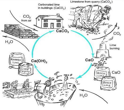
The diagrams below and opposite illustrate the chemical process by which building limes are produced.
The rst is the lime cycle for ‘pure’ or non-hydraulic lime. After the stone has been burnt the lime may be used in three di erent forms for a variety of mixes. These are as quicklime, dry hydrate powder (hydrated lime), or putty.
The Lime Cycle DiagramfromBuildingwithLime
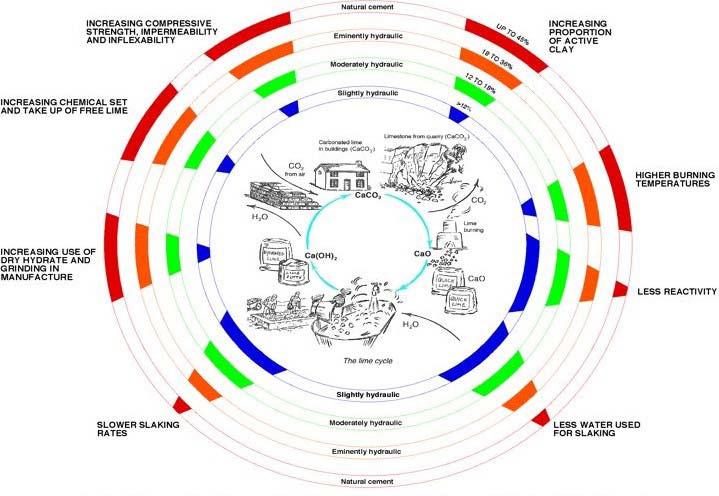
The diagram above illustrates some of the variations that occur with di erent types of hydraulic lime following a similar lime cycle.
By the 19th century di erent types of building limes had been classi ed in a way that was generally accepted in the building industry at the time. Following research by Smeaton (1757) and Vicat (1818) the principal range of traditional building limes were described as set out in the table on the next page. Subsequently, since mechanical methods of production have developed a variety of new hydraulic limes of substantially greater strength and faster set are now also readily available. These may not all be suitable for the sympathetic repair of old buildings particularly the strongest and least permeable, and some may cause long term damage if used inappropriately.
Regional distribution of limestone
One of the world’s most abundant materials is limestone. It is widely available in many countries in various forms. Small scale lime burning and lime kilns were a common sight for centuries until the advent of large scale mechanised and centralised production. Its geological distribution in the British Isles is recorded in detail on BGS survey maps. Relating this information to historical records of limestone quarries and the history of lime production is rewarding for those who wish to take this subject further.
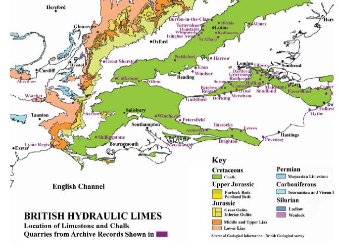
From before the medieval period up to the beginning of the 20th century, when lime was produced on a small scale, it was mostly sourced locally close to the place of construction. The exception was sometimes for high status buildings, particularly if the speci ed type of lime was not available locally, or for engineering purposes. By the time the di erent types of lime were classi ed there was a greater understanding of their regional distribution. The South of England has extensive chalk deposits which have been quarried for lime from before the 13th century much of which was used for building in London, as well as locally to the quarries. Either pure or slightly hydraulic limes can be produced from chalk depending on the bed selected.
Traditional feebly and moderately hydraulic limes have been obtained in the past from various limestone deposits and particularly in the UK from di erent strata of Blue Lias. This formation runs from Lyme Regis diagonally north-east past the Wash. It also runs southwards to West Somerset’s north coast near Bridgewater and crosses the Severn Estuary to Aberthaw near Cardi .
There are carboniferous deposits in South Wales, in Pembrokshire, and in North Wales and Anglesey. These produce mostly non-hydraulic limes. Oolitic deposits, which also produce non-hydraulic and lean limes, run through the Cotswolds roughly parallel to the Blue Lias beds. There is a belt of magnesian limestone on the line of the Pennines running from Nottingham to Catterick in the north. Extensive deposits of carboniferous limestone
occur in deep pockets in the Midlands, to the north of this and to the north and west of Skipton, across the north Pennines and in many areas of Scotland and Ireland.
The location of some historic limestone quarries and lime production in the south of England can be related to regional geology as given in the example below.
Large centralised plants continue to produce an ample supply of indigenous non-hydraulic lime.
Unfortunately there is no UK production of traditional natural hydraulic lime from British limestone at the time of writing and all natural hydraulic lime is imported.
Properties of building limes and lime-based mixes
Breathability and vapour permeability
Brie y, this is one of lime’s most important properties because it handles moisture movements in a way that protects other materials. It is instrumental in assisting buildings and their component parts to dry out, the avoidance of condensation, and the improvement of comfort conditions. This is in contrast to the opposite e ects of harder and/or less permeable materials particularly when introduced into older buildings.
Workability
Once a mix is prepared and before nal set it will be in a constant state of change. It is designed to be malleable when placed but to set and harden afterwards. If this set takes place at an unpredictable rate the mix will be di cult to work. Limes assist good workability which makes them a pleasure to use. They help a mix to
remain mouldable for long periods, penetrate the background, and achieve good early bonding.
Durability
When used appropriately and with good detailing, lime mixes are extremely durable as the many examples of Roman and Medieval buildings including aqueducts, bridges, castles and cathedrals standing today demonstrate.
Self-healing
Water penetration into ne cracks can dissolve ‘free’ lime and transport it from adjacent material. Over time lime is deposited and may heal the cracks. As an example the redistribution of calcium carbonate this way is similar to the way stalagmites and stalactites are formed.
Sacri cial protection
Lime mortar mixes and paints may be used sacri cially to protect other materials due to their rm but soft nature. This is particularly helpful for
the conservation of delicate surfaces, sculpture and mouldings of historic importance and for the sympathetic maintenance of old buildings.
Pozzolanic set
The ability of lime used with pozzolanic materials to provide a hydraulic set is a remarkably versatile property. Chemically pozzolans are similar to the active clays in hydraulic limes described above. They have no hydraulic binding qualities on their own but when combined with lime in appropriate proportions will produce a hydraulic set. A wide range of strengths and permeability can be achieved with the combination of non-hydraulic or hydraulic limes and pozzolans this way. Many pozzolans have been used in the past including brick dust, volcanic ash and other ashes from various industrial processes. These are all in the form of powder after burning but similar although generally less robust e ects may occur with lime and lime and unburnt clays, for example for the stabilization of clay soils.
High alkalinity
Lime is highly alkaline which is one of the reasons for its many bene cial uses including as a mild disinfectant, cleaning agent and medically as an antidote to acidity. It has been used for water puri cation and for lime nishes to create hygienic surfaces and improve comfort conditions within buildings for thousands of years.
Quicklime instability
Quicklime (CaO) has a natural a nity with water and the chemical reaction with it (to produce calcium hydroxide) is so rapid that it can boil in the process. The reaction can be violent, it can burn the skin and should be treated with caution.
Variable forms of building limes
Unlike most binders lime may be used in several forms. The principal ones are quicklime, dry hydrate powder and lime putty. Quicklime may be used as large lump lime, granulated lime or powder and recently as micro lime for specialist conservation purposes. Dry hydrate is favoured by the larger manufacturers and suppliers as it is convenient to pack and transport in bags. A
disadvantage of this is that it is not as reactive as fresh quicklime and its reactivity will reduce the longer it is stored. It is, however, mostly the way hydraulic limes and the majority of nonhydraulic limes are supplied. Provided lime putty is sealed from the air or simply stored under water it improves with age, and it is the preferred form of lime for use by traditional plasterers and for achieving ne nishes and details.
Double Refraction
The double refraction of light through calcite crystals gives a unique aesthetic to lime nishes. This combines a soft texture with a luster that has a liveliness and delight of its own. Lime nishes can rapidly develop a rich patina which has a glowing translucent quality and are beautiful.
Ecological Bene ts
The use of lime as a binder reduces the detrimental e ects that some construction methods have on the environment.
- Lime has less embodied energy than Portland Cement (OPC)
- Lime absorbs carbon dioxide in the setting process of carbonation reducing CO2 to a far greater extent than OPC
- The gentle binding properties of lime enable full reuse of other materials such as bricks and blocks resulting in a considerable energy saving for alterations and rebuilding
- Lime can be produced locally on a small scale reducing or eliminating transport distances
- Small quantities of lime can protect otherwise vulnerable, very low energy materials such as earth construction, straw bales and wattle and daub
Decay mechanisms
Generally, or building elements that use lime as a binder, the principal decay mechanisms are:
- Lack of maintenance
- Poor or defective weathering details
- Wet conditions/water damage
- Frost damage
- Impact damage
- Atmospheric pollution – salts, sulphates etc.
resulting in stained and defective surfaces and building material erosion
- Vegetation, plant and mould growth
- Recent and sometimes earlier interventions, with inappropriate materials for alterations, additions and covering original surfaces
- Ferrous xing corrosion
- Structural movement
- E orescence
There are also other speci c decay mechanisms that apply to items which include:
- Ceiling plaster
- Wall plaster
- External render
- Mortar and pointing
- Limewash
Ceiling plaster
This may be weakened by a number of decay mechanisms including the deterioration of supporting wood laths due to insect attack, xings corrosion (nail rot), wet rot and dry rot. Support may also be weakened by accessing oor voids for maintenance and particularly the installation of services and insulation which may damage the plaster key by breaking nibs. Vibration and movement of oorboards and oor joists may induce cracking or cause partial loss of key.
Wall plaster and external render
Where this has been applied to a lath background causes of decay can be similar to that described above for ceilings. Plaster and render on solid backgrounds may also deteriorate due to the various general decay mechanisms listed above in the introduction to this section.
Lime mortar and pointing
One of the principal bene ts of lime mortars is that they protect adjacent masonry by their vapour permeability. Evaporating moisture draws out salts. These tend to damage mortar surfaces which decay in preference to the adjacent masonry. The mortar is acting sacri cially and weathers back slowly during this process. The simple unobtrusive intervention of repointing with matching lime mortar will be required at intervals subject to
severity of exposure conditions and weathering.
Limewash
Decay may be caused by any of the general items above as well as weathering over the long term due to exposure conditions or aking related to poor or inappropriate previous application. A brief guide to the preparation, application and aftercare of limewash is given elsewhere in this section.
Repair option
The cause of defects
This is often to be found, not in the lime bound material itself but in external factors. Prior to repair the cause or causes of the defect need to be identi ed and remedied. Sometimes if the defect is not severe, this is all that is required following drying out, plus possibly minor making good and surface treatment.
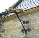
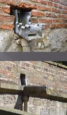
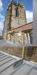
Maintenance
Probably the most common cause of deterioration is excessive moisture due to defective drainage. The repair and maintenance of drainage systems is important although frequently overlooked. Gutters, downpipes and gullies may be blocked. Defects to roof nishes may be out of sight or di cult to access. Causes of moisture retention and build up adjacent to walls, such as due to raised ground levels should be eliminated or drained and isolated from the building fabric. Moisture build up inside buildings, largely generated in areas such as kitchens and bathrooms, may be reduced or prevented by providing good ventilation and maximizing the use of permeable materials and nishes.
Defective detailing
E ective weathering details are an intrinsic part of good building design. They have been used frequently in forms that shed surface water away from plane surfaces protecting them from saturation in vulnerable areas. Drip grooves below cills and copings are typical examples. Lime plaster has many attributes but it is not strong in positions liable to impact damage. Detailing at external corners for example has traditionally been treated
in a number of ways. Internally, xing “sta beads” of timber or other hard material on corners was common practice protecting these and other vulnerable arrises. Externally, stone quoins and rounded or splayed surface at corners were often used.
Over time details like these, that protect render and plasterwork, may be eroded or lost completely. Where they are damaged or missing they should be repaired or reinstated in their original form.
Water damage
Following investigation and elimination of the cause of water damage the saturated area is best allowed to dry out slowly before repair. Attempting to dry out quickly with forced heating in a localized area is not advisable as this may lead to further deterioration and cracking. It may also damage adjacent fabric, particularly timber. Once dry, the area can then be cleaned, irreparable material carefully removed and lime mixes matching the original prepared and the area patch repaired. After drying out lime bound mixes should be carefully checked as they may not have deteriorate and can be conserved.
Frost damage
Once a mix has fully cured, and in the case of most limes, dried, it is unlikely to be damaged by frost. If applied in cold weather however (say 5°C or below) it may take months to mature. During this time it is vulnerable to frost attack and should be protected against freezing. Also, refer to the section on aftercare.
Impact damage
Materials may be damaged by light impact or abrasion and to varying degrees up to destruction by vehicle collision. Light damage may involve cutting out irreparable render to a rm edge, providing a key to this, damping down and replacing with matching material where the original is missing. This can be done provided the background is sound and will provide a good key. The more severe the impact the more likely the supporting structure will have been damaged. This needs to be carefully checked and repaired
before re-rendering onto a rm and well keyed background. It is also important to reinstate weathering and protective details such as corner beads which may also have been damaged by impact.
Atmospheric pollution and staining
Changes in fuel used industrially and domestically, the Clean Air Act, and a growing awareness of the health hazards caused by polluted air have resulted in an almost smoke free atmosphere in many towns and cities today. This is in contrast to the smoke and soot stained conditions, including the London ‘smogs’ prevalent within living memory.
There are various pollutants carried in the air and by water, in the past and up to the present that have varied over time. Probably the most common of these that damage lime binders are acidic or those that contain sulphates. Acidic rain and smoke are typical. Lime is an alkali so may be dissolved by acids. Smoke from coal contains sulphates that can combine with lime to form calcium sulphate or gypsum which is water soluble. A traditional method of dealing with these problems was to limewash on a regular basis. In addition to improving appearance the limewash acts as a sacri cial coating to protect the surface on which it is applied.
There is now a range of proprietary materials for removing surface discoloration and deposits but it is important to proceed with caution before attempting the cleaning or removal of old nishes, particularly limewash. These may cover historically important murals or other decorations particularly in buildings used for worship or other community activities. It is advisable that an initial investigation by a specialist conservator is carried out before attempting to remove old surface nishes of this nature especially from ancient buildings.
Vegetation and mould growth
Unchecked vegetation against lime render will cause damage and regular maintenance to keep it clear of walls is important. Some plants are more damaging than others. Creepers such as ivy will nd crevices and cracks and over time can destroy
a nish completely once established on lime bound surfaces.
Mould and lichen removal initially may simply be by applying hot water (just below boiling temperature) and a light brushing or sponging o . External render incorporating hydraulic lime or natural cement will stand this treatment better than internal plaster. Various poultice methods of mould removal have been successful including quicklime poulticing. If acidic fungicides are used they should be thoroughly cleaned o after use and no residue left on the cleaned surface as this may dissolve the lime.
Inappropriate interventions
Alterations, additions maintenance and repairs with materials that are inappropriate for old buildings are frequently the cause of deterioration. There is an incompatibility between two building construction methods. The older traditional, often solid wall, methods rely on the absorption and evaporation of moisture from a solid but permeable building fabric whilst most new systems rely on dense impermeable materials, sheeting and membranes to form waterproof barriers.
When impermeable materials are used on or in conjunction with permeable construction they prevent evaporation and trap moisture. The resultant decay can be dealt with, and further decay and moisture build up prevented by removing or separating impermeable material from the original building fabric. Lime based mortars, plasters and renders, and vapour permeable paints are suitable to use as they reduce the risk of further moisture build up after damaging impermeable materials have been removed and the area has dried out. Care needs to be taken to avoid unnecessary removal where this may cause damage or loss of original fabric.
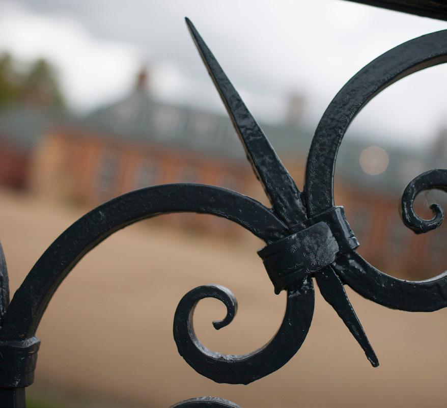
Ferrous xings
When iron is exposed to damp and the air it corrodes and expands. The conservation of ironwork, particularly decorative wrought-iron and castings is another subject but deteriorating
iron xings can damage lime nishes, by cracking them due to expansion, and depositing rust stains. Depending on the severity of corrosion and historic signi cance of the ironwork, the xings should be either carefully removed, cleaned and coated for re- xing, tipped with stainless steel or similar, or replaced with a non-ferrous xing. Lime render or mortar round the xing can then be made good.
Structural movement and cracking
A building’s stability is largely dependent on ground conditions, foundations and form of superstructure. If one, or any combination of these vary or become unstable in the same building, di erential settlement or movement may occur. Materials that depend on this structural support, typically lime plaster and renders may crack on the line of di erential movement. If cracking is ongoing and serious structurally, a structural engineer specialising in historic building conservation should be consulted.
If, as is frequently the case, cracking is slight and long established, carefully removing loose material and lling with matching lime mortar using best practice of preparation, application and aftercare is appropriate. It may help to adjust the mix relative to the width of the crack. In general terms a larger size aggregate of sharp sand or crushed stone and more hair will be preferable for the wider cracks to reduce shrinkage whilst the smallest and least amount of aggregate is needed for the nest ssures. The preparation of samples to test these before carrying out the main work is helpful in selecting the most suitable mix
E orescence
Evaporating moisture through walls may carry various minerals and compounds or ‘salts’ which are deposited on the surface as powder or froth like crystals. The salts may be from the walling itself or from earth or other material adjacent to it. The transfer of salts this way is not always harmful but over a long period may cause a breakdown of lime bound mixes. If severe it may cause deterioration and erosion of masonry surfaces. In the short term the e orescence can be brushed away and if the
source of moisture is located and isolated form the wall e orescence will reduce as it dries out.
Ceiling plaster
Where ceilings have lost their key and the plaster is bulging or sagging, it would reduce the risk of loss to provide temporary soft support on the underside, and propping from below until the repair can be e ected.
In some areas improving adhesion to the background may be su cient. One method is by lime grouting and carefully inserting screws and washers into shallow recessed pockets in the levelling coat (second coat) of plaster, with the surface keyed and deep enough to plaster over for concealment. It would be advisable for this to be carried out by an experienced plasterer or conservator. Details of this repair method are given in the English Heritage Practical Conservation Series. Only after the supporting structure is fully stable and in sound repair should cracks and minor surface defects to the plaster be made good otherwise cracking is likely to reoccur due to continued background movement.
Lime plaster ceilings that have a weakened support due to defective laths and missing nibs and/or cracking may be strengthened in various other ways. Minimum intervention is preferable in order to conserve all original plaster, mouldings and decorative work that remains without further loss or damage. For the most severe decay and
structural defects specialist consultants, craftsmen or conservators should be consulted. In some cases techniques for suspending plasterwork on hangers from the oor structure above that have been developed for areas where laths have been lost due to decay, or there is no longer a plaster key, may be appropriate. Details of these repair methods are also set out in the English Heritage Practical Conservation Series, Mortars, Renders and Plasters.
Internal wall plaster
Original sound internal lime plaster is unlikely to need repair unless it has been subject to failures of the supporting background laths, structural movement or water penetration as outlined above. Once the cause of these defects has been corrected the exact condition of the plaster should be determined. Bulging plaster due to lack of key often has the potential of being saved by xing back to its supporting background in a similar way to re- xing ceiling plaster particularly if well haired. In addition, where there is a solid background lime grouting carefully introduced into the void where the key has been lost will assist consolidation and adhesion.
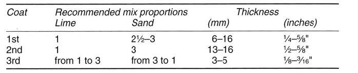
Where old plane plaster has lost the majority of its binding properties or is so badly damaged it cannot be saved, the defective area can be cut out and patch repaired or re-plastered. Typical traditional mixes for well haired three coat plasterwork are set out below.
TablesreproducedfromBuildingwithLime
External wall render
There are many types of external lime render. These vary for reason of climate, building exposure, availability of local materials and design preference. Of the various decay mechanisms water saturation and frost damage are probably the most common in the British Isles. Where render has been destroyed it can be cut out and repaired in principle in a similar way to internal plaster. There is a wide range of external render nishes however, which also vary to achieve durability, deal with exposure conditions, status of the building and regional di erences. It is therefore important to establish the precise nature of the original render to ensure a satisfactory match. These are, for example, in timber framed buildings feebly hydraulic lime skim coat on wattle and daub panels or lime stabilised soil, two-coat work of lime and sand, three-coat work of the same, plane and textured surface nishes, lined out render, rusticated work, roughcast on a render coat on lath, harling or wet dash in two or more coats on solid backgrounds. A list of publications that contain technical details and repair recommendations for the wide range of di erent lime renders and nishes is given at the end of this chapter.
Lime mortars
These vary for the same reasons as lime renders above with additional variations to accommodate mortar joint width and type of masonry unit. Historically there are also various types of mortar joint nish, pro le, and techniques such as tuck pointing and galleting.
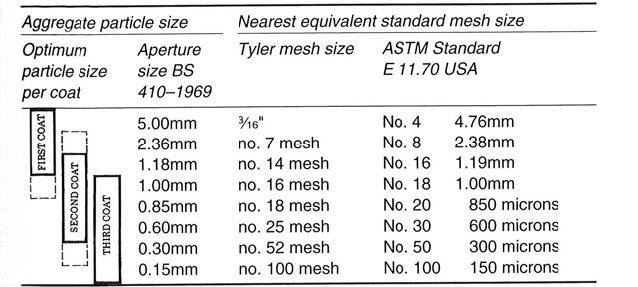
- Mortar joint width is a guide to the optimum aggregate particle size and proportion required in the mix. This varies from ne ashlar
or gauged brickwork joints, needing little or no aggregate of 1mm particle size or less, to wide random rubble joints of 10mm or over requiring higher proportions of large aggregate up to 5mm or more.
- Masonry units, usually bricks or stone, may be hard and dense or soft, permeable and possibly friable. A delicate balance needs to be struck between achieving an adequate weathering quality to the mortar with its ability, after full curing and set, to be more permeable than the adjoining masonry units. Most lime mortars take two years or more to fully cure. Manufacturers should provide compressive strengths and permeability gures after two years from application for mortars made with their limes. Not all lime suppliers have this information readily to hand. On larger projects an allowance for the laboratory testing of existing and new materials may well be of bene t.
- Whilst mortar joints appear to be relatively small and insigni cant compared to the mass of a building as a whole, the overall e ect of the appropriate size, colour and texture of all the joints is extremely signi cant to the aesthetic of an elevation. There are cases where a simple ush joint of the original width and with a matching colour, size of aggregate and durability is satisfactory for replacing defective or missing areas of mortar. There are however, other pointing techniques and pro les, such as tuck pointing, or gauged brickwork which are integral to the original design and should be carefully retained. This is usually a skilled process for which specialist craftsmen or conservators may be required or to give advice.
Limewash weathering
A good limewash is gently washable but a poorly applied limewash can be rubbed o . Good limewash will have carbonated well after application to the wall to form a continuous lm of calcium carbonate. It is used for decoration and protection both inside and outside buildings. A regular application of a thin coat of limewash is a traditional method of protection particularly e ective on softer and more porous building surfaces.
Less e ective “whitewashes” are made from dry hydrate but cannot achieve all the qualities of a good limewash from putty or quicklime. Mould inhibitors include formaldehyde and other watersoluble inhibitors such as Formalin. Externally, any water soluble disinfectants can be used including owers of sulphur, copper sulphate, crude carbolic acid or coal tar disinfectants. Marks and stains can be gently cleaned using water and soap suds or mild detergent. Colours are achieved through the addition of mainly natural earth pigments in small quantities in the nal coat and all pigments used should be alkali-resistant.
As with all repairs incorporating lime binders, the background surface on which the limewash is to be applied should be clean, rm and damped down prior to application, although, limewash will not adhere to smooth hard surfaces. Similarly an understanding of thorough preparation, application and aftercare during the whole process is necessary as it is for the successful use of all work with building limes. Thin coats of limewash, similar in consistency to very thin skimmed milk, and four or more of them will give better results than a few thicker coats.
Workmanship and materials
Setting properties
Working with building limes can be enjoyable and rewarding as they are such a pleasure to use. They are one of the most versatile binders with a wide range of properties. In the main, to bene t from this versatility, particularly softness and permeability, they need to be treated with
care. Setting properties depend on carbonation, a slow absorption of carbon-dioxide from the air entirely for the non-hydraulic limes, and increasing chemical set for the various hydraulic limes and natural cements.
Best practice
Best results are achieved with good practice, this has been recognised by craftsmen during centuries of developing various techniques for using this remarkably diverse material. Of the various way to use many types of lime there is a common thread. That is the importance of moisture control and thorough preparation of materials, careful application and regular aftercare.
Preparation
Preparation of materials includes ensuring that the lime is fully reactive. That it is reasonably fresh and has not absorbed carbon dioxide which reduces its binding properties; and that the sand or other aggregate is sharp, well graded and has a particle size appropriate for the joint or coat thickness. Water content is also important, mixes that are too wet will be di cult to apply and strength will be reduced.
Application
Application can be enjoyable as the workability of lime binders is usually good, forgiving, and better than many others, but care to avoid overworking needs to be taken into account. Most lime mixes are malleable and slow setting so there is usually time to re-work areas before nal set. The risk is that if a surface is re-worked too often this will bring the lime (fat) to the surface and weaken the material below. Background surfaces on which lime is applied should always be rm, have a good key, be clean and damped down in preparation for the work.
Aftercare
Aftercare is mainly to assist curing, to protect surfaces whilst they cure and dry, and ensure that this happens slowly. All free lime needs carbon dioxide to set which is carried by water rstly absorbed into the mix and then released as it
evaporates. The chemical set of hydraulic limes is assisted by warm damp conditions. For best results it has been found that assisting lime mixes to cure by regular damping down, two or three times a day for a week or more, improves the set.
Protection against frost is also important and winter working should be avoided if possible unless adequate protection or heating is provided. Ideal curing temperatures are in the order of 10°C or above in conjunction with regular damping down. Standard speci cations state that all limework should not be carried out if temperatures are 3°C and falling or work recommence until they are at a minimum of 5°C and rising. It is essential that freshly applied mixes and work that has not fully cured is not subjected to freezing conditions.
Further reading and useful organisations Publications
Allen, G., et al., Hydraulic Lime Mortar for Stone, Brick and Block Masonry, Donhead, Shaftesbury, 2003
Brocklebank, J et al., The Building Limes Forum selected papers, Building Limes in Conservation, Donhead Publishing Limited, Shaftsbury, 2012
Cowper, A.D., Lime and Lime Mortars, HMSO, London 1927, reprinted by Donhead, 1998
Henry A and Stewart J. Practical Building Conservation, Mortars, Renders and Plaster, English Heritage, Ashgate Publishing Limited, Franham, 2011
Holmes, S., To Wake a Gentle Giant – Grey Chalk Limes Test the Standards, The Journal of the Building Limes Forum, Volume 13, UK, 2006
Holmes, S. and Rowan, B., Lime Stablized Construction International Organisation for
Migration (IOM), Islamabad, 2016
Holmes, S and Wingate, M., Building with Lime: A Practical Introduction Intermediate Technology Publications Ltd., London 1997, Practical Action Publishing, Rugby, 2003
Hughes, P. The Need for Old Buildings to “Breath”, SPAB Information Sheet 4, London, 1986 + SPAB “Breathability” De nition, 2016
Hunt, R., SPAB Brie ng, Lime, Supplement to the SPAB Magazine, 2015
Hunt, R. and Suhr, M., Old House Handbook, Lincoln Limited, London, 2008
McAfee, P., Lime Works, The Building Limes Forum of Ireland, Dublin, 2009
Scho eld, J., Lime in Building, A Practical Guide, Black Dog Press, Crediton, revised 3rd edition, 1999
Vicat, L.J., A Practical and scienti c Treatises on Calcareous Mortars and Cements, Arti cial and Natural, Captain J.T. Smith, John Weale, London, 1837, reprinted by Donhead,
Weismann, A. and Bryce, K., Using Natural Finishes, Green Books Limited, Totnes, 2008
Wingate, M., An Introduction to Building Limes, SPAB Information Sheet 9, London c1987
The Building Limes Forum admin@buildinglimesforum.org.uk
The Building Limes Forum Ireland info@bl .net
Acknowledgements
Michael Wingate – Joint author of Building with Lime
Je Orton – Joint author of the chapters on lime plaster in Building with Lime
3 Mechanical and electrical services
Tim Bowden BSc, CEng, MCIBSE, MIET Consultant, Ramboll
Introduction
There have been ‘services’ in buildings since the earliest times in the form of open res for heating and lighting. The Romans developed sophisticated heating, water supply and drainage systems and in hot climates an approach of allowing incoming air to pass over an area of water allowed evaporative cooling to moderate internal temperatures. Oil lamps consisting of hollowed out stones have been used since the Stone Age period and then later developed into purpose made terracotta lamps.
In the early 19th century the development of town gas allowed the use of gas lighting.
The Victorian period brought about signi cant advances in ‘building services’ with the development of ‘central heating’ installations, distributed hot and cold water systems, air conditioning (controlling temperature and humidity). The most important developments during this period were those of Michael Faraday (electromagnetic induction) and Joseph Swan (incandescent lamp) which led to the development of electrical services and electric lighting in buildings.
Types of engineering services
This short note does not give su cient space to consider and give detailed descriptions of every type of service in building but the most common services and a short summary is listed below:
Heating
Provided to meet occupant comfort requirements or at lower levels to protect the building and contents from deterioration.
Can be of many forms, often consists of pipe work carrying hot water into heat emitters, radiators (although termed radiators most of the heat from radiators is convective); fan coil units (a hot water
coil with a fan forcing air over it); hot water into pipework buried in the oor (under oor heating). The potential energy source producing the hot water also has a wide range of options including oil/gas boiler, bio-mass boiler, CHP (combined heat and power unit) or heat pump. Direct acting n also be provided electrically e.g. direct acting heaters (basic electric re or fan heater), storage heaters, and under- oor electric or electric infrared. Sometimes systems are hybrids of the above e.g. warm air circulated under the oor (similar to a Roman hypocaust system) with the warm air being produced by passing air over a hot water coil.
The selection of the most appropriate energy source and distribution / delivery equipment will depend upon a wide range of factors including the nature of the building, (lightweight / heavyweight, fabric performance and if it can be improved); the nature / type of the existing heating system; level of heating required as it may be di erent for di erent areas of the building; hours of use / operation, space / extent of intervention needed to incorporate any new proposals; capital costs vs operation costs energy consumption and CO2 emissions. Heating is often the most considered and challenging aspect of services in historic buildings.
Ventilation
Provided to give fresh air to the occupants or dispel moist / contaminated air from kitchens or WCs. Natural ventilation (opening windows) is the most common approach. In many historic buildings ducts or ue arrangements are provided to assist ventilation. In some of these arrangements the air ow rate is controlled via dampers in others such a ue for an open re the ow is uncontrolled.
Hot and cold water services
Provided to kitchen, bathroom and laundry facilities. Generally distributed using copper or plastic pipe systems (lead was used previously but now not acceptable for potable uses). Hot water There have been ‘services’ in buildings since the
earliest times in the form of open res for heating and lighting. The Romans developed sophisticated heating, water supply and drainage systems and in hot climates an approach of allowing incoming air to pass over an area of water allowed evaporative cooling to moderate internal temperatures. Oil lamps consisting of hollowed out stones have been used since the Stone Age period and then later developed into purpose made terracotta lamps.
In the early 19th century the development of town gas allowed the use of gas lighting.
The Victorian period brought about signi cant advances in ‘building services’ with the development of ‘central heating’ installations, distributed hot and cold water systems, air conditioning (controlling temperature and humidity). The most important developments during this period were those of Michael Faraday (electromagnetic induction) and Joseph Swan (incandescent lamp) which led to the development of electrical services and electric lighting in buildings.
Types of engineering services
This short note does not give su cient space to consider and give detailed descriptions of every type of service in building but the most common services and a short summary is listed below:
Heating
Provided to meet occupant comfort requirements or at lower levels to protect the building and contents from deterioration.
Can be of many forms, often consists of pipe work carrying hot water into heat emitters, radiators (although termed radiators most of the heat from radiators is convective); fan coil units (a hot water coil with a fan forcing air over it); hot water into pipework buried in the oor (under oor heating). The potential energy source producing the hot water also has a wide range of options including oil/gas boiler, bio-mass boiler, CHP (combined heat and power unit) or heat pump. Direct acting gas red radiant heating is also an option. Heating
can also be provided electrically e.g. direct acting heaters (basic electric re or fan heater), storage heaters, and under- oor electric or electric infrared. Sometimes systems are hybrids of the above e.g. warm air circulated under the oor (similar to a Roman hypocaust system) with the warm air being produced by passing air over a hot water coil.
The selection of the most appropriate energy source and distribution / delivery equipment will depend upon a wide range of factors including the nature of the building, (lightweight / heavyweight, fabric performance and if it can be improved); the nature / type of the existing heating system; level of heating required as it may be di erent for di erent areas of the building; hours of use / operation, space / extent of intervention needed to incorporate any new proposals; capital costs vs operation costs energy consumption and CO2 emissions. Heating is often the most considered and challenging aspect of services in historic buildings
Ventilation
Provided to give ‘fresh air’ to the occupants or dispel moist / contaminated air from say kitchens or WC’s. Natural ventilation (opening windows) is the most common approach. In many historic buildings ducts or ue arrangements are provided to assist ventilation. In some of these arrangements the air ow rate is ‘controlled’ via dampers in others such a ue for an open re the ow is uncontrolled.
Hot and cold water services
Provided to kitchen, bathroom and laundry facilities. Generally distributed using copper or plastic pipe systems (lead was used previously but now not acceptable for potable uses). Hot water is generally either produced centrally (e.g. at a boiler) or point of use (e.g. an electric heater next to a sink). Hot water produced centrally requires a pipework pumped ow and return loop to avoid excessive water draw o before the hot water appears at the tap. The follow and return system also prevents the water temperature falling too low and therefore reducing the risk of the build-up of legionella bacteria.
Above and below ground drainage
Internal above ground drainage is generally linked to the water services noted above. Ideally water services and drainage should be located in the lower levels of the building to lessen the impact in the event of a leak.
Electrical services
Electrical services developed in the later 19th century. Cragside in Northumberland was one of the rst building to have hydro-electric power in 1870 to power arc lamps with these replaced by incandescent lamps in 1880. John Ryland’s library had a generator in the basement that powered the lighting installation in 1890. Electricity was generated where it was used. However by 1910 only 2% of households had electricity. It was not until the development of the National Grid in 1926 and the promotion of electricity as a clean fuel as opposed to all the smoke from domestic chimneys that take up increased.
Electricity is now taken for granted to operate a whole host of appliances, including IT equipment and lighting.
Electrical services are provided primarily to meet two requirements the rst being to meet the needs of the occupant e.g. lighting and power provision the second to reduce risks such as the provision of re detection, security installations and lightning protection.
Electrical services are generally smaller physically than mechanical services and therefore they can generally be more easily accommodated in existing buildings although there are generally more of them. Since electrical services are from the 1880’s they will be a previous ‘intervention’ in earlier buildings. The wiring systems consist generally consist of copper conductors covered by insulation with additional mechanical protection either from a conduit system (metal or plastic tube within which the cables run) or by increased protection in the design of the cable sheath (such as a further level of insulation material, a lead covering, steel wire armouring or copper sheath) covering the insulation material. Some electrical systems such as
IT ‘Wi-Fi’ and re detection systems also make use of radio links between devices to avoid the need for cables interconnecting every device.
Work involving services to historic buildings should follow the SPAB principles of conservation:
Information
Understand the building before making any changes including:
• The current use, hours of operation, assessment of the building thermal performance.
• Review any ‘as installed’ information.
• Note the building features such as builder’s/ ventilation ducts, primary service routes likely air and moisture movement.
• Consider if any aspect of the ‘services installation’ has any historic signi cance.
• Review any temperature / humidity records and energy use data that exist so that subsequent changes can be monitored against this.
• Also consider if the building structure, fabric or contents are a ected by the current temperature regime and if changes are proposed what is the likely impact of this.
• Understand if the building and services have any special protection and the consents required for any work.
Essential work
Consider carefully if the work is essential. Ideally co-ordinate any building services work with other building work so that other specialists are available e.g. a joiner to carefully lift oorboards. Consider if existing systems can be retained to perform their original use particularly if they are early examples of building services installations.
Fit new to old
Where new installations are installed re-use existing service routes and avoid opening up previously undisturbed areas or creating new service routes. A useful approach for more highly
serviced areas such as wash room spaces is the provision of free standing ‘pods’ or de ned areas allowing subsequent refurbishment within a restricted area. Also consider the likely route of ‘leaks’ if they occur. Alterations should be compatible with the building rather than working against it.
Repair not restoration
Historic buildings have lives of many hundreds of years and the engineering services are likely to be a transitory intervention due to their shorter life that is normally in the region of 25 to 50 years. Where possible retain existing early building services performing their original function. Also consider the likely life of the services, in some buildings such as cathedrals the requirements are unlikely to change whereas in a commercial historic building a new tenant may have di erent requirements. (Potentially match the life of the services / degree of opening up undertaken installing them to consider this). Existing services also contribute to the character of the building even if they are no longer in operation. Retain them where their signi cance warrants this. Ensure that services are simple to operate and maintain. The work should aim to be reversible so that future services replacement’s / repairs can be carried out. Make a presumption against the loss of historic fabric by creating new service routes for example, locate socket outlets on the side of the room where oorboards have already been lifted as opposed to lifting oorboards that have not been disturbed previously.
Workmanship
Careful and considered workmanship does justice to ne buildings. This is equally applicable to building services where care during installation will provide a solution that minimises damage to the building fabric and are sympathetic to the appearance of the building, fabric or contents.
Materials
The materials use for building services systems and equipment need to consider the design life, minimising maintenance and energy / carbon e ciency.
Respect of age
Just because items are old does not necessarily mean that they are not functioning correctly. An example of this is early ‘radiators’ in buildings which make a signi cant contribution to the character of the building. There is potential for these heating systems to be retained operational in their entirety or at least the radiators themselves retained as part of a new heating system.
Integrity
Early building services particularly those that remain operational bond with the building itself and strengthen the link with the building. Even where services have been removed by earlier interventions retaining where possible building features for their original function such as ventilation ducts, ues, air intake positions etc. enhance an understanding of the building.
Responsible methods
Services solutions and interventions should avoid fabric loss and be reversible. Bespoke solutions are often required that suit the building special characteristics. Where possible implement solutions as a sample / trial and monitor (potentially over a heating season) to understand the impact and for agreement with other stakeholders.
Complement not parody
New work should express modern needs in a modern language. Items like lighting and radiators are probably the most visual items of building services equipment. Where these items are new they should relate to the existing building in responsive way by considering their size and scale and the existing rhythm of the building.
Regular maintenance
This is required to maintain the e ciency of systems and meet mandatory health and safety requirements, such as the testing of re alarm, emergency lighting, lightning protection and the general electrical installations. Many ‘protection’ systems are designed to higher property standard levels and not merely to provide protection to occupants.
This maintenance should also include as a minimum the monitoring and review of temperature in the primary spaces in order to compare with previous data and the monitoring of energy and water consumption to allow benchmarking and targeting to reduce consumption. Systems also potentially require seasonal adjustment / ne tuning particularly during the rst year of operation and where systems have been operating for some time to also consider changes of use / occupancy that may have occurred since the original design, installation and commissioning.
Energy and CO2 emissions
The Government (Dec 2020) has made a commitment to reduce CO2 emissions to net zero by 2050 and atleast 68% reduction in greenhouse gas emissions by 2030, compared to 1990 base levels.
The National Trust has committed to become carbon net zero by 2030 particularly by increasing tree planting as carbon sinks.
The Church of England’s General Synod has set new targets for all parts of the church to work to become carbon ‘net zero’ by 2030. This is a challenging target particularly with the limited land areas for carbon sinks and limited nance available in most Parishes.
It is important to adopt a systematic approach regarding carbon emissions for Building.
Where possible re-using existing building will be more carbon e cient than demolishing them and rebuilding a new building.
In terms of reducing the operational carbon from building services systems the overall approach should be:
• Reduce the demand / requirement.
• Use an appropriate method of distributing / providing the heating where required
• Meet the demand / requirement for heat in the
most carbon e cient way possible.
• Consider obtaining energy from renewable sources.
It is important that the options considered also take into account, capital costs, life cycle costs, planning requirements / listed building consent in addition to cabon impacts so that the most appropriate solution is taken forward.
There are simple ways of improving the energy and carbon e ciency of nearly all buildings including:
Improved management of existing systems
Ensure a person has responsibility for and champions energy and carbon reduction and encourages good energy housekeeping. Review if the current regime for operating systems is it still appropriate or can it be modi ed to better match the needs of the buildings contents and occupants? Historic buildings often bene t from providing heating at lower levels than those normally required for occupant comfort, even if only by a few degrees below comfort levels with the associated reductions in energy and CO2 emissions.
Reducing levels further to where the internal temperature is only a few degrees above the external temperature is often referred to as ‘conservation heating’ this is designed to maintain relative humidity in the region of 40% to 60%, a band that is more suitable to prevent deterioration of organic materials. This may not be appropriate for buildings that are more continuously occupied, and some compromises often have to be made. Part of this management role will involve keeping proper records of ‘as installed information’, operating and maintenance manuals, details of maintenance undertaken and energy consumption details. It is also useful to have a log book making notes of dates that work has been undertaken or defects identi ed.
Fabric improvements
The importance of the appearance of historic buildings usually means that the opportunity to add insulation materials particularly to walls and oors is limited. The rst step should be to consider reducing unwanted in ltration by actions such as repair / restoration of doors / windows and draught proo ng, repair of any holes in the construction; restoring window shutters and adding heavy curtains. At the same time care should be taken to provide an appropriate amount of ventilation to remove any internally generated moisture.
Adding insulation is generally more di cult in historic buildings; the provision of discrete secondary glazing is an option that can be cost e ective. Also void spaces, particularly roof voids can be insulated ideally using natural materials e.g. therma eece type insulation that are vapour permeable.
Selecting e cient plant and systems
The selection of systems is often de ned by the existing installation and the nature of the building use. Consider if a more localised solution may be appropriate such as small electric heaters for example under the pews of a church rather than a system that attempts to heat the whole building. If a more centralised system exists or is proposed the heat energy source should be selected with high e ciency and low carbon in mind.
As a minimum where mains gas is available boilers should be high e ciency condensing type with other options being other LZCT (low and zero carbon technology) such as bio-mass boilers that burn wood pellets or chips, heat pumps either ground or air source or CHP (combined heat and power) which require a signi cant hot water demand on a daily basis to be viable. The LZCT solutions generally have higher capital costs but allow some recovery of this via RHI (renewable heat incentives).
Improved controls
This may not require any new equipment but just a need to understand the capabilities of the existing controls and utilise them. Review if time and
temperature settings are appropriate and consider if some areas of the building can be operated to a di erent regime to reduce consumption. Review areas with natural light and consider switching o arti cial light in these areas.
Energy e cient lighting
There have been signi cant improvements in the e cacy of light sources (the lumen output of the source compared to the power input lm/watt), the quality of light and the lamp life performance. Fluorescent sources are suitable and cost e ective for most installations. LED lighting is currently more expensive but will give a better return over time. LED lighting is likely to predominate as capital costs fall.
Renewables
This refers to energy generation systems where the source of energy is from a natural source such as wind, solar and water where the energy store is naturally replenished therefore no carbon emissions associated with the generation.
Some systems produce electricity from solar PV panels, wind turbines, hydro systems; other such as solar thermal and biomass boilers produce heat energy. Of all the technologies solar PV is normally the easiest to implement. It requires no real consideration of the building loads since excess energy is fed back into the electrical supply system and providing there is a suitable south facing roof planning approval is usually straightforward even on listed buildings. There are many examples of this technology being implemented. Renewable systems are paid for the energy they generate under the OFGEM feed in tari s and renewable heat incentives.
Electricity grid
As UK power stations have moved away from coal and towards renewables, the national grid has begun to ‘decarbonise’. Electric heating is now cleaner than gas or oil heating, and this trend is expected to continue. Churches can go beyond this and purchase or generate ‘green’ renewable electricity, which further reduces the carbon footprint of electricity as a fuel source.
Further reading
BSRIA illustrated guide to Electrical Services BG32/2005
BSRIA illustrated guide to Mechanical Services BG31/2012
CIBSE Guide for Building Services in Historic Buildings.
Historic England BeEST Practice 1 – Principles of Conservation Practice: Engineering the past to meet the needs of the future.
Historic England –Energy E ciency and Historic Buildings
CIBSE Heritage Group Website - www.hevacheritage.org/
Government Carbon Reduction Targets - UK sets ambitious new climate target ahead of UN Summit - GOV.UK (www.gov.uk)
National Trust Carbon Commitment - National Trust outlines fresh ambition in landmark speech by Director General | National Trust
Church of England Carbon Commitment - General Synod sets 2030 Net Zero carbon target | The Church of England
4 Timber
Dr Joseph Bispham
Oak: 13th - 17th century
Contemporary records show that a variety of species of tree woods were used in medieval England for construction purposes. Recorded in the Henry III building accounts are woods such as oak, elm, sweet chestnut, poplar and the many varieties of fruitwoods (Colvin 1971). The single most important species of tree supplying timber and wood for building construction in Britain before the 18th century was the oak (Quercus robur).Oak is the timber that has survived in our medieval building to a greater extent than any other, oak was, and still is, the most popular native hard wood used for the construction of timber frame buildings in Britain.
Much of the medieval carpenter’s timber was sourced for construction from locally managed woodland. The managed forest and woodland areas were creations of under-wood. This was the area of woodland, to the height of a tree that is manageable. These areas of managed woodland produced small sections of timber from coppicing and pollarding the trees. Coppicing is when a tree is cut to the ground leaving the base of the tree known as the stool (Evans, 1984: 69). The tree regenerates from shoots that continue to grow from the side of tree stools and become large enough to use as timber. Pollarding is the same principle, but instead of the tree being cut to the ground, it is cut leaving 2-3 metres above the ground, giving the forthcoming shoots protection from grazing animals.
Since the 12th century, the history of coppice work is well recorded. This type of woodland management and regeneration gave a regular crop of wood and timber for domestic and building purposes and was common practice up until 150 years ago(Evans, 1984: 69).
In the management of woodland certain trees of value, such as the oak, would be selected
to grow through the under-wood canopy so becoming more mature. The selected trees went on to develop straight boles with fewer branches lower down the trunk and with the crowns much higher. These were the ones that once felled and converted would have been used for the longer sections of timber that were needed, for example, in the construction of timber frame buildings, barns and hall houses. They would also have been of greater monetary value than the unrestricted growth of timber from the eld oaks.
Historically, there has always been a demand for English oak as a construction timber and periodically intense demand made it a scarce commodity, particularly when demand for timber for a great project removed all local supplies. In times of timber shortage imported timbers from the Baltic countries were a substitute for home grown timber, Oak, beech and pine were the main timbers traded, oated down the rivers Memel, Bug and Vistula to the Baltic ports of Memel and Riga. Their nal destination was England or the Low Countries,
England could no longer have a reliance on home grown building materials such as the oak. In a little over 150 years England experienced a building material shortage, a Great Fire and the architectural in uences of the Grand Tour, all of these in uenced the type of building materials used and methods of building construction.
Materials available for the carpenter builder; limitations of use
England never had a reforestation policy and as a result the availability of native timber was at times in short supply for building construction. In the 17th century, as a result of the Elizabethan housing boom, the consumption of oak for fuel and the
growth of the Navy, timber for construction was at times in short supply. The master carpenter needed to source timber for construction and quality timber was not, at times, easily obtainable for general building.
There were a number of limitations that had to be overcome in order to construct secular timber dwellings of a less important nature. The following limitations were to have a direct bearing on the growth of trade of imported softwoods into England as a building material and the eventual displacement of native timber in favour of imported softwoods.
a) Availability of material
b) Size of available timber
c) Seasoning, conversion of the material and workability
The carpenter would have been familiar with these limitations and the constraints were to in uence the size and character of timber frame constructions.
a) Availability of Timber
The limitations that the carpenter had to deal with, from the later medieval period into the 16th century, were to have an in uence on the changing use from oak, as the most commonly used constructional timber, to softwood. The change was to occur later in the 17th century.
England never had a reforestation policy and as a result the availability of native timber was at times in short supply for building construction. In the 17th century, as a result of the Elizabethan housing boom, the consumption of oak for fuel and the growth of the Navy, timber for construction was at times in short supply. The master carpenter needed to source timber for construction and quality timber was not, at times, easily obtainable for general building.
b) Size of available timber
Size of timber was a factor that in uenced the scale of the building or hall size, in particular the width of the property, which would be governed
by the length of timber required for the tie beams. The height of the rooms would also be in uenced by the length of the bole of oak for conversion to the required post sizes. In the search for a largesection oak with dimensions above 300 mm (12 inches) square for a principal jowl post, the village carpenter generally would need to source from a eld oak. Field oaks, unlike the oak from managed woodland, would have been very much older, and slower grown, they would not be as straight. Once converted by cutting or splitting the oak trunk through the middle, lengthways, and upending the timber to display the thickened end that was originally towards the ground, the thick section (jowel) was able to accommodate the tenons of the tie beam and the wall plate each tree chosen for this purpose would then supply a pair of jowl posts with enough length to accommodate most secular dwellings.
c) Seasoning, conversion of the material and workability
Much of the oak used in the timber frame construction of dwellings was green oak (unseasoned). The moisture content in an oak tree is so great when rst felled that it can commonly account for half its weight. As an indication of the weight of water trapped in the cells of a fresh felled oak, rstly, if it is calculated that an oak tree contains 100% moisture content at felling (this gure would not be excessive), secondly, take into account the dry weight, which is constant at Metric equivalent (40-50 lb per cubic foot) (Titmuss, 1965:160), then the moisture would account for (40-50lb) of water, trapped in the cells of the oak, per cubic (foot). With such large quantities of water trapped in the wood bres it would have been impossible to season the oak to a dry state fully in the large sections required for use as beams, girders, and posts, before the construction of a timber frame building took place. Indeed, the framing of many of the timber buildings that survive today was speci cally cut and fashioned with green oak. The carpenter in history would have been very familiar with the bene ts of converting and working oak when it is green as it cuts and fashions very much easier in the green
state. Oak continues to harden as it dries and as part of the drying process it will move and twist, this twisting has the e ect of tightening up the tenon into the mortise joint giving more strength to the structure.
A change of style and Softwood imports 17th19th century.
The demand for a ordable literature from professionals and craftsmen are evidence of the 18th-century craftsman and professionals’ quest for knowledge in construction and architectural detailing.
The mid-18th century saw extensive publications with new constructional, joinery and architectural detailing promoted through illustrated books such as The British Carpenter by Francis Price (Price, 1735). These pattern books brought the most fashionable of London architectural style to the wealthy in all parts of the Kingdom and eventually had the e ect of regularizing the architectural building style of England by gentri cation of the older properties in villages and towns. The quality of slow-grown old stand pine timber such as Pinus sylvestris that was cut inland and sent down river to the Baltic ports of Memel and Riga in the 18th century was recognised for its quality by architects and craftsmen of the period (Bispham, 2015). Softwood dried more quickly which reduced its weight and helped to keep it stable. Slow-grown timber with tight growth rings and vertical grain was used extensively for quality joinery such as doors, frames, and the box frame windows with vertical sliding sashes and thin glazing bars.
Analysis: Cause of failure
Excess moisture is the single most problematic cause of all failure of wooden structures whether the failure occurs on parts of a timber-framed building or on external joinery such as, doors, door-cases or window frames. Timber and wood needs to be kept dry or it will attract insect and or fungi: “All of the fungi and insects that damage timbers in European buildings belong to the woodland outside” (Ridout, 2015: 12). The beetle doesn’t know it’s in a listed building, it thinks it’s in a wood-land.
Repairs
Con dence in Repair
The professional specifying and overseeing a repair to any wooden structure needs to demonstrate to the client con dence that the repair has been executed with craft skill and competence, and with quality materials. These things, along with a lasting maintenance programme, will give longevity. Flagging up the need for maintenance is not a new concept:
The same principles apply when repairing any wooden structure whether it is a large timber structure or joinery items. The repairs should be undertaken with quality materials and employing good craft practices. In this way the repair will become part of the original structure. Once a good repair is completed it will serve for as long as the original item is maintained and kept in working order.
Before undertaking repairs to a rotten section of wood an assessment should be carried out. Each repair will need to be assessed on its own merit and a close inspection of the original construction will not only show construction details but also the quality and species of wood originally used. Any new sections of wood used in the repairs need to be the same species as the piece being repaired i.e. oak for oak, or pine for pine and of the same dimensions and matching pro les as the original.
Repairs to timber-framed buildings
Method of repair: carpentry craft practice
One of the most common repairs to an historic timber-frame building is repair or replacement of the sole plate / ground sill. The sole plate is the
horizontal section of timber nearest the ground level, with all the principle posts and studwork xed vertically into it. With moisture from the ground level and the water run-o from the face of the building and down any vertical timbers the sole plate is one of the most vulnerable of timber parts to a timber-frame building. Some elements of a timber-frame such as plates and beams are of such a size that it is very di cult to obtain them in an air seasoned condition (17% moisture content) in which case discus with the timber merchant stock available with a number of years felled air dried.
Smaller sections of oak up to 100mm thick can be obtained kiln dried. Although much of the oak used in England for new build is from French mills English Oak is available and may be preferable for repairs for our historic buildings. As a guide the price quoted to the author for purchasing British oak given spring 2017 was that British oak had approximately a 17% high cost than the French oak. This estimate of cost was from one supplier that the author has used and is purely a guide there will be a number of other suppliers with other estimates of costing.
Materials: oak
Historically the wide use of oak as a constructional timber points to a recognition of oak heartwood for strength, durability and its greater resistance to rot and beetle infestation. When kept dry the properties that are to be found in the physical make-up of English oak as a species of timber give it a longevity that no other English hardwood species has.
In Britain we have two native species of oak: peduculate oak or Quercus robur; and sessile oak or Quercus petraea (Mitchell, A. F. 1985: 67)
. The peduculate oak can be identi ed as having stalk-less leaves with the acorns on stalks. The sessile oaks have a leaf stalk and acorns without stalks.
Both of these species of oak are used for construction and merchants do not di erentiate
between them.
Heartwood: the part of the tree that produces the most durable wood once the tree is felled and converted. The heartwood takes many years to form and is the support for crown. It is the inactive central region of the tree, in the case of oak in particular, the tree’s waste products are stored here, and contribute to colour and most importantly its durability.
Sapwood: the outer part of the tree, it is the living part of the tree that conducts water up to the crown. This part of the tree is not durable when converted for its wood use as it contains sugars and starches which are food for wood-boring insects and fungi.
When ordering fresh sawn new oak take into account the water content of green oak (see above seasoning, conversion of the material and workability). Once the tree is converted into timber sections, the moisture expels through the end grain of the wood at a far greater rate than the tangential, at sawn side of a beam or plank. The radial or quarter-sawn part of a piece will have the least expellation of moisture and is the most stable
When large sections of green oak such as plates or beams are to be used in repairs, it is advisable, because of the high moisture content in green oak, to seal the end-grain while work is being carried out. This will allow moisture to evaporate at a more controlled rate, and will reduce the likelihood of the end-grain splitting, forming, say, a star shake.
Conservation and repair to softwood joinery Method of repair: joinery craft practice
Repairs of a joinery nature will need to be more speci c than that of carpentry in that a note should be taken on the quality and growth patterns of the grain of the wood, and to the extent to which any sound wood needs to be removed enabling a permanent connection with the section of wood being repaired and the new piece of wood. In the case of joinery repairs it is essential that some of the sound wood of the item being repaired needs
to be removed allowing the new wood to be glued and xed to a sound material.
Fixing a new section of wood to the degraded wood on the item being repaired will lead to failure of the joint between old and new. The quality and closeness of grain of wood material used in the repair needs to match as near as possible that of the original. This will lessen the di erential movement at the point of old and new ( Bispham, 2001).
In joining a new section of wood to the original a method of repair needs to be chosen so as to remove as little as possible of any of the original mouldings. The cut line on the original joinery needs to be at the back of the mouldings. The success of the repair will rely on the joining of the two pieces of wood together as one. The splice/ scarf joint should be cut at a shallow angle running along the grain of the wood as illustrated. The cut gives a larger surface area with the run of the grain to glue the two faces together. Fixings should if possible be to the inner faces or sides. If exterior xings are required, use stainless steel and use wooden dowels for tenons (Bispham, 2001).
Joinery Speci cation
Pinus sylvestris
Historically known as Baltic Pine or from its port of export such as Memel Fir or Riga Pine. Today timber merchants stock this softwood as: European redwood or Scots Pine.
It is still possible to obtain quality timber from established timber merchants which in the case of small projects would be selected piece by piece. European redwood (Pinus sylvestris) from Sweden, Finland or Russia is a good choice for most joinery repairs. Redwood comes in grades for joinery known in the timber trade as ‘1-3 unsorted red’ the lower the number the better the grade but if selecting try to obtain slower grown wood with tighter ring growth. Another option for specifying a quality material for joinery repairs is that of Douglas r (Pseudotsuga menziesii) speci ed as grade ‘No 2 clear and better’, selection is important (Bispham, 2001).
Today a good timber merchant will hold stocks of timber listed above and they will have been kilndried. At the inspection stage moisture readings should be taken of the historic joinery in the zones of sound wood, especially in the areas where the splicing of new to old is to take place. When splicing the new wood to the old section it is advisable to keep the moisture content to within a % or two this will prevent subsequent movement.
Quality of material
Today the managed plantation softwood forests aim to produce timber as quickly and economically as possible. The modern fast-grown softwood that is generally used in construction once it has been pressure impregnated with preservatives is not suited to quality repairs of historic joinery.
Preservative Treatment
Redwood (Pinus sylvestris) is less durable than that of Douglas Fir (Pseudotsuga menziesii) and (part of sentence missing?) that due to the generally less durable nature of redwood, but not necessarily Douglas r, that the new wood that is to be used in the repair, is speci ed as preservative treated. If this is the case, all the sections of wood that are to be used in the repair will need to be cut and tted then sent for treatment. Before xing it is essential that the preservative-carrying uids have fully evaporated from the wood, making it ready to be glued. With or without preservative treatment, when the repair is complete all the wood must be primed and sealed, especially the end grain.
Cost
Generally the extra cost for quality timber for repairs is quite minimal set against the labour cost of repairs. The specifying of quality materials for repairs is essential if the repair is seen to be the positive response and preferred choice to that of replacement.
Further reading
Colvin, H.M. (Ed) (1971)The King’s works Henry iii building accounts, Open University Press.
Evans, J. (1984) Silviculture of Broadleaved Woodland, HMSO.Forestry Commission Bulletin 62.(ISBN 0 11 710154 0 )
Mitchell, A. F (1985)Broadleaves, London HMSO. Forestry Commission Booklet no.20. (ISBN 0 11 710039 0)
Dollinger, P. (1964) The German Hansa, London, MACMILLAN & CO LTD (ISBN333 064941)
Salmon, W. (1734) Palladio Londinensis: or The London art of building
Rackham, O.(1986) The Woods of South-East Essex. (ISBN 0 9511863 0 2)
Forrester, H. (1976) Timber Framed Houses of Essex, Regency Press, London.
Titmuss, F.H. (1965) Commercial Timbers of the world, London Technical Press Ltd
Bispham, J. (2001) Wood focus, issue no 4 spring 2001.pp 4-5. The magazine of the Institute of Wood Science.
Bispham, J. (2016) SPAB Brie ng Windows & doors pp8-10 ISSN 2054-7684, Architectural Timber, History and Conservation.
Bispham, J. (2015) The Building Conservation Directory, 22 edition 2015 pp.123-126. ISBN 978-1-9009915-717
Latham, B. (1957) Timber: A Historical Survey, its Development and Distribution, George Harrap & Co, London.
Price, F. (1735) The British Carpenter, 2nd edition. Salzman, L.F. (1997) Building of England down to 1540. Oxford University Press, Special ed.
Sandpiper Books. (ISBN 0 19 817158 7)
Ridout, B. (2015) Timber Decay in Buildings and its Treatment (ISBN 978-1-874146-03-2)
5 Roofs
Peter G Pace Conservation architect
Roo ng elements
Clay tiles – pantiles and plain
Natural clay handmade unglazed tiles will weather naturally, attracting lichen and moss. Arti cially weathered ones will darken over time.
Using second hand tiles is risky as their average life span is only 70 -100 years, and they can contain microscopic fractures unseen to the eye, which become very susceptible to frost action. The cost of re-roo ng is mostly in the labour, preparation, plant, etc. and the material cost of the tile represents a small percentage of the overall cost.
Where access is easy and the building not of high value, carefully selected pantiles can be re used but the client should be made aware the chances of failure are signi cant. A balance is to be struck between using old weathered tiles with their wonderful patina of age, and the risk of failure. Surprisingly some very old hand made tiles from 1600 can be more robust than 19th and 20th cent. machine made tiles. Where surviving ancient tiles of such the historic nature are encountered they are worth every e ort to save and re use. Re using handmade tiles can cause di culties when it comes to re- laying, as the tiles can vary widely in curvature, depending upon the individuals who made them. A man with long thin arm pressing clay into a mould might make the pantile dish shallower than someone with say a short, strong arm, pressing harder. Firing in clamp ovens can also cause much distortion. Be aware selecting reclaimed pantiles for relaying is very time consuming, and will add signi cantly to costs. The result is often unsatisfactory and may rely on underfelt to make water proof. Underfelt should never be relied upon as anything but a belt and braces, to catch water should the roof covering become damaged.
Old buildings rarely had a secondary covering of
under felt. Pantiles were often laid on a lime mortar bed on top of split or sawn lathes, to give a degree of protection from drifting snow (which nds its way into roof spaces very easily!)
Where modern breathable felts are applied to old roofs remember this will often require counter lathes which can raise the roof by a few inches, not much but enough to cause di cult problems at abutments such as gable upstand copings etc.
Plain tiles
These are even more susceptible to frost damage and I personably would never reuse 19th or 20th century cent plain tiles.
A typical detail in the past was to tilt the eaves courses to help slow down the rainwater run o as it joined the gutter. This is essential for both practical and aesthetic reasons to retain. However note the pitch of the tilted course is not nearly as steep as the main slope, and modern clay is often not red to such high temperatures as old, thus rendering the tilted tile to frost damage, and no claim can be made against the company producing the tile as they have minimum pitches which often fall outside the old shallow eaves pitch. The answer is to select a di erent harder tile, or even use stone slates on eaves course – a traditional solution.
Roofs and rainwater goods and drainage go hand in hand. Roo ng grants from Historic England often rightly require all three elements to be addressed at the same time.
Replacing existing rainwater goods in the same Cast Iron may not be su cient. Are the gutters big enough? Are there su cient down comers to take the run o ? Will drains be accessible for rodding out? With re-roo ng there is often a good opportunity to review the system in detail and make improvement without necessarily adversely changing the character of the building?
Historic decorative goods should be retained at all costs, even where damaged and very costly to replace. For example a 19th hopper head designed by G.E. Street contained splits and badly rusted backs, resulting in leaking for years, and almost impossible to reach the back without removing – with the inherent risk the brittle cast-iron could break up completely. The solution in this instance was to insert a lead lining which e ectively by passed the problems, yet left the hopper looking e ciently necessary.
There may be times to remove gutters entirely, if the eaves overhang, and there are no projections such as buttresses below. These arrangements are called dripping eaves and were a common feature in times past. In the illustration above right, the nave gutters were inaccessible, except with great di culty and the chance of damaging the Westmorland slated aisle roof. By adding a lead undercloak to the nave eaves, this extends the eaves to allow a good discharge well clear of the clerestory wall below- and also allowed for the removal of cement render put up to combat the over owing gutters, enabling the wall to breathe. The lower chancel gutters with their ne gutter brackets, were left as they could be easily reached from a ladder.
Many churches no longer have the means to maintain gutters, and much damage to the buildings is due to blocked, over owing gutters. Blocked parapet gutters backing up and soaking into wall tops and timber wall plates, are even more damaging, introducing a slow insidious process, often not discovered until wet rot had gained a signi cant hold.
The answer is to make sure water can get away should blockages occur, and this can be achieved by tting over ow chutes, something the Edwardian architects were good at.
At junctions with walls, roof abutments ashing can be vulnerable to excess concentrations of water discharging from a fall pipe, especially in high winds, and the introduction of a lead U channel can stop water backing up behind the lead ashing.
Sheet metal: lead
Lead is a wonderful long lasting material, easily worked into soft shapes, and capable of being re cast to give hundreds of year’s life. Its great disadvantage lies in its inability to contract, only expand. Lead must be allowed room to expand due to heat(sunshine), with at least one free edge left . If xed at both ends it will quickly fracture. This means lead must be laid in a manner to stop water penetrating through the un- xed ends. This is achieved on roof slopes by joints with high upstands – either wood roll joints or hollow roll joints.
In gutters joints are spaced at regular intervals (2.2 m) with down stands, which are e ective as
Leadchannel
water cannot go uphill - unless the gutter becomes blocked and backs up su ciently to overwhelm the upstand - hence the vital need for over ows. Lead used to be laid in very large sheets, making both handling di cult and chances of fracturing great. From early 20th century the size of lead sheets and lengths has consistently been reduced.
Whilst all this helps lead survive longer it is still important to use heavy grades of lead – code 6 as a minimum but ideally code 8 for roof slopes and gutters. Code 3 is ne for soakers, and code 5 for ashings. Again as with tiles, the cost of the material is not a large proportion of the overall cost. (Lead, contrary to popular myth does not actually have a large scrap value – and is very di cult to move.
As the Lead Sheet Association (LSA) regularly revises their recommendations on sizing and details of lead work, it is worth looking at the way a lead roof on a building has worked in the past and see if improvements can be made without adversely a ecting the character. Fortunately roofs in lead are often at and therefore generally out of sight behind parapets, and the opportunity may arises where some radical changes can be made, to improve both maintenance, and lengthen the life of the roof.
An example can be seen at Castle Howard – a Grade I listed building, of national importance. Firstly, a look at the history of the building tells the story. Vanbrugh was not an architect, yet designed a radically new building. He left details of how to make the building work to his associate architect Nicholas Hawksmoor, who clearly had a struggle. Numerous light wells and di ering levels to the roofs made for a very complicated layout. And not wanting to see external rainwater pipes spoiling his facades, Vanbrugh directed rainwater to the central Hall of the building, with dispersal through internal rainwater pipes set in the thickness of the walls. A serious re in 1943 left much of the historic roof structures severely damaged, and some roofs were temporarily waterproofed with asbestos sheet. The question of rainwater dispersal was not still addressed. When funds were at last available
in 1990 to repair/renew the roofs, a re-structuring of the roofs was seen as necessary to avoid several hundred years of blocked internal fall pies and ooding to stucco painted plasterwork, marble tting, and decorative contents.
The solution was to make the rainwater disperse to the exterior, and by altering heights of roofs, and the falls, rainwater was taken to new lead fall pipes to the courtyards within the building, thereby avoiding adding pipes to external facades.
CastleHoward
CastleHowardroofbycentraldome,beforeand after
Lead work can su er from underside corrosion caused by condensation which oxidises and eats away the lead, becoming only apparent when the lead is so thin pinholes appears. Coupled with fractures associated with long sheets, large roofs are vulnerable to high maintenance. Again any reroo ng programme needs to address issue such as reducing maintenance and making sure rainwater dispersal is e cient.
BowesMuseumBarnardCastle
Newleadworkandgutterlinings
Here at the Bowes Museum, unused light wells were in lled to reduce the many di erent levels of roof, valley gutters were raised to allow proper falls and larger upstand (drips) to conform to LSA guidance. Insulation and ventilation was introduced to reduce the possibility of condensation to underside of roof slopes. Stone lead lined gutters (a constant source of leaks) were re lined in lead coated stainless steel in very long lengths to avoid joints (the advantage of SS over lead), and over ows introduced. Trace heating tapes on thermostats were introduced to melt any build-up of snow which might block gutters and outlets which might lead to internal water penetration, damaging priceless contents (The Bowes Museum has the largest display of Decorative Arts outside the V&A in London.).
All this modi cation work is completely unseen from ground level.
Stainless steel
A very strong, with none of the disadvantages of lead. It can expand and contract, and subsequently be laid in very long lengths without joints. It has no scrap value, and can be coated in lead to resemble lead which will not wear o , and be jointed with round rolls, to become virtually indistinguishable from a lead roof.
The disadvantage lies in its di culty to work, unlike soft lead, and requires skilled craftsmen. Being a hard surface, rain striking can be noisy. Thick sound deadening insulation has to be added beneath – which helps insulate against heat loss.
ExamplesofSSwithcappedbattens
RecentexamplesofSSwoodrollbattens
Slating
There are a number of di erent types of slate from sedimentary slate (compressed shale such as Welsh slate, Burlington), stone (Collyweston limestone or Yorkstone sandstone slate), and Volcanic Ash slate (Westmorland). The principles of laying slate are much the same, with three layers of the material to provide the waterproof covering, head or centre nailed. Copper nailing remains the best material for xing,as copper is less likely to break a slate if struck too hard.
Welsh slate is very hardy, and provided the nail holes are still sound can be successfully re used, though the same comments apply re: the costs of materials versus the overall roo ng costs. Ideally new slate from Britain should be used . Bringing slate from foreign countries reduces home grown quarries, and may not be suitable for English climate. Westmorland slate tends to soften on the underside, and sometimes in the centre, making detection di cult. Destructive testing is advised on samples from several places on a roof.
TheBowesMuseum:Westmorelandslate,replaced innew
Di culties experienced at the Bowes Museum are worth recounting. First the existing slates appeared to be sound on both sides and the experienced roo ng contractor advised they could be reused. However the slates were deceptive and further testing showed they were soft inside – a rare occurrence. This resulted in choosing new slates in the re-roo ng.(adding only 5% to overall cost of the whole re-roo ng project. )
The slates were xed to sarking boarding, posing a dilemma as to how underfelt could be used to help as a double protection to the important contents of the building. The sarking boarding of over 1 inch thick, was sound , but if counter battens were placed on the boarding to take felt then all the junctions with the lead ridges to domes etc. would be out of sync. It was decided to re x directly to the sarking boarding, keeping to the original detail, and rely on good workmanship to keep the roofs watertight.
Stone slates are very tough and can often be reused. They should be xed ideally with alloy pegs or even traditional oak pegs (though the skill is fast disappearing).Many stone slates were xed in 19th cent using wrought iron nails which rust and split the head of the slate making them di cult to reuse, and often are only found upon removing. Slates using random and diminishing courses such as Westmorland, Burlington, and Yorkshire greystone have di culties with salvaging. The courses di er in thickness, and cannot be easily cut down and substituted in smaller course, as the courses will not lie level. Selecting and sorting salvaged slates is an important element to be taken into consideration when costing out the options.
Thatching
There are now very few speci c areas in the British Isles where thatch remains common. Changes in modern agriculture practice means new varieties of wheat with short stalks are unsuitable for thatching. Supply from reed beds in Norfolk, Heather Ling, and bracket thatch in North Yorkshire or Scotland is now rare. Historically, thatching methods and materials re ected strong local traditions, but increasingly techniques are becoming standardised with regional distinctiveness being slowly eroded. Most thatching materials are now imported from Eastern Europe.
Research on the thatch of a building should be made before any repair work starts, to determine what the thatch material is (there may be several layers of di ering material stretching back over many years), and whether or not it might still be available.
Much evidence of local tradition could be lost without this awareness and careful recording, much like on an archaeological site, is essential.
In Scotland a collaborative venture is in process between Historic Environment Scotland (HES), and SPAB , to record thatched buildings and categorise in terms of material - Straw, ,Marram grass, Heather, Bracken, and Rush etc. are amongst more than
the 15 materials already identi ed. The survey will inform a strategic approach to the conservation and protection of remaining thatched building. Many of the more interesting thatches survive under corrugated tin sheeting, having laid un -touched for the last 100 years or so. – see ww.historicenvironment.scott
Modern materials
Very few modern materials such as single-ply felts, built-up felts, GRP, pro led PVC coated steel sheeting, etc., are appropriate for ancient building, for a number of reasons.
These materials have short lifespans of between 15 – 30 years. Guarantees issued by companies are rarely honoured, as subsidence, awkward abutments etc. are common on ancient buildings evolved over centuries, making conditions less than ideal for precision materials.
The aim should be for repairs to last a minimum of 60 -120 + years (depending on the material), and to encourage the continuation of craftsmanship using historical detailing, and a continuation of local sources of materials.
However occasionally there can be overwhelming
reasons to use a modern material on a listed building.
One example is Birley Spar, a listed building of 1840’s, swallowed in the suburbs of She eld, where vandalism was so rife the chances of a renewed welsh slate roof surviving for just a few days, let alone years, was unlikely. A metal pro led sheet, emulating welsh slate, of the type seen on a Burger King fast food outlet, was used to protect the building from wind and rain, whilst also providing a breathing space of a few years for the community to persuade local young people to engage in the project.
6 Metalwork
Brian Hall Hall Conservation
What is metal?
Chemically speaking there are 91 metals in the periodic table, some common, many extremely rare. The metals found in old buildings and the metals that we are concerned with are copper, brass, bronze, iron, lead, zinc and tin, along with gold and silver. More modern buildings may also contain aluminium, nickel, and steels.
The majority of metals are found in combination with other minerals and oxides as ores (rocks containing metal-bearing compounds usually oxides). Extracting a metal from its ore is essentially a heat process, more or less complicated depending on the metal. This process is called smelting. When heated, metal ore, silicates and carbon solids reduce to liquid metal, gasses and slag - silicates that were combined with the ore which vitrify to become a crude glass.
Smelting forces the metal into a high energy state meaning it is chemically unstable. Corrosion is the process of returning to its more stable state by oxidisation and combining with other minerals.
The history and development of metals and metalworking stretches over millennia and became ever more e cient and sophisticated through time and experiment. Metals were developed for particular applications by special treatments or combined, as alloys to give special characteristics, e.g. hardness, ‘springiness’, or re ectiveness.
Aplications
Metals have a multitude of uses. Their strength and resilience has led to their structural use in buildings and bridges as well as decorative elements and, of course, the tools necessary to build the buildings.
The metals which we are principally concerned with are:
Iron and steel: closely related materials with a wide range of characteristics, all produced from basic iron ore but by slightly varying processes. From basic wrought iron in the original charcoal red Bloomery, which reduces the iron to a spongy mass (the ‘bloom’) combined with it’s vitri ed associated minerals and carbon monoxide, through to a wide range of irons and steels used for a range of applications, which evolved through various developments and improvements.
Charcoal wrought iron is an iron alloy with a very low carbon content. When the bloom is taken out of the Bloomery it is hammered to drive out most of the impurities. Some remains to form brous inclusions of slag which gives it a grain resembling that of timber and is visible when it is etched or bent to the point of failure. Toughness, malleability, ductility, easy workability and corrosion resistance made it a unique material for a wide selection of uses. No longer produced, it can be found in recycled form, although expensive and variable in quantities and quality.
By the end of the eighteenth century the demand for iron was huge. With the development of the Blast Furnace and substitution of charcoal for coke smelting of iron was revolutionised. This produced ‘pig iron’ in great tonnages at lower cost. With limited use in crude form, it is processed to produce puddled wrought iron and di erent forms of cast iron.
Puddled wrought iron; re ned by puddling, it contains less slag, less sulphur and has a very low carbon content. Generally more consistent than earlier irons, it could be produced in far greater quantities. It features similar properties to charcoal iron and is worked in the same way.
Cast iron was introduced into Western Europe during the 15th century, but practical uses were limited because of its brittleness and manufacturing limitations. It is a ferrous alloy that has been heated until it lique es and then poured into a mould made principally of damp sand where it solidi es.
Following the introduction of coke as a fuel, cast iron was produced by re-melting pig iron, often together with substantial quantities of scrap iron, scrap steel, coke and limestone to help remove contaminants. Di erent alloy constituents a ect its colour when fractured, which give some of the types their names.
Grey cast iron is characterised by its graphite microstructure which causes fractures in it to have a grey appearance. It is the most commonly used cast iron and the most widely used cast material based on weight. Grey cast iron has less tensile strength and shock resistance than steel, but its compressive strength is comparable to low and medium carbon steel.
White cast iron. Surface fractures in this cast iron have a white appearance. It has good hardness and abrasion resistance and is often used as the wear surface in machinery, but not so much in construction.
Malleable cast iron starts as a white iron casting which is then heat-treated to give it a degree of exibility. Mostly it is used in machine parts, or as pipework in buildings.
Ductile cast iron is a recent development. The properties are similar to malleable iron, but parts can be cast with larger sections and can be easily welded.
Mild steel. Steel was produced in Bloomery furnaces for thousands of years, but large-scale, industrial use was not achieved until the invention of the Bessemer process in the mid nineteenth century. This heralded a new era of mass-produced steel. From then on, mild steel completely replaced wrought iron. Today, steel is one of the most common man-made materials in the world and is used widely in the construction industry.
Specialist steels. There are many specialist steels which are produced for a wide variety of situations and applications. Few are likely to be encountered in buildings, the most common of these are:
Stainless steel. Stainless steel in buildings is practical, water resistant, easy to clean and aesthetic. It was much in vogue during the Art Deco period and remains a popular material. It is essentially a steel/chromium alloy. The stainless steel commonly used in interior settings and for domestic use, SAE304, is not totally rust resistant. Where the highest level of corrosion resistance to weather, very wet conditions, chlorides or high humidity are encountered, the grade will almost certainly be SAE 316L and that is the recognised material for use in situations to replace or reinforce existing materials.
Corten steel is a steel alloy that is often used in outdoor building works. It was designed to eliminate the need for painting, and establish its own decorative nish. When exposed to weather it will develop a self limiting rusted patina.
Reinforcing bar also commonly called rebar are high tensile steel rods used to strengthen and reinforce concrete slabs and structures. When rebar is set into concrete during the pouring process it greatly enhances the tensile strength.
Copper has a long association with buildings as roo ng, pipework and decorative elements. Copper is very durable in unpolluted atmospheres, but is vulnerable to ‘acid rain’, especially where rainwater run o repeatedly runs or drips onto another section.
Polished copper counter tops and table tops are decorative and have an added advantage of being antimicrobial. Copper can also be formed for decorative purposes by ‘repoussé’, embossing from the reverse side to raise a three dimensional design and chasing. Scale can be anything from a simple nger plate to the Statue of Liberty.
Copper is also used as a metal for electroplating other metals. In the nineteenth century, a process of electroplating the interior of moulds was developed known as ‘Elecrotype’ or ‘Electrocast’. The copper was allowed to build up to a considerable thickness until it could become a freestanding sculpture or decorative element.
Bronze is principally a copper/tin alloy. Sophisticated bronze sculptures and decorative work have been found throughout the ancient world. After the collapse of the Roman Empire, these traditions and techniques were neglected in Europe until the Renaissance, when bronze casting once again came to the fore as a sculpture and decorative material.
The nal process in the creation of a bronze sculpture or decorative element is the patina or nish that is applied to the surface. A chemically induced form of corrosion of the metal, that gives it it’s colour, depending on the combination of chemicals and minerals that are applied and the surface it is applied to.
The patina is usually extremely thin and fragile and most outdoor bronzes have su ered a period of neglect at some time or other. Even bronzes that remain in a protected indoors environment can have their patina worn. For outdoor bronze, pollutants in rainfall will quickly strip away the applied patina. Atmospheric pollutants turn the bronze green while eroding the surface. This process irretrievably changes the surface. There is often no record of what the original patina was like, but despite this it became the norm in the recent past to repatinate bronze to a bland uniform brown. All chemical repatination is irreversible In situ, repatination is a hazardous process since the chemicals involved are often dangerous and environmentally damaging. More recently it has been recognised that the naturally accrued stable green patina has an aesthetic and historical value. Current practice is to stabilise and protect it.
Brass is a copper/zinc alloy that is both decorative and functional, and is used in both visible and hidden parts of xtures and ttings in buildings. It takes a high polish and ‘Victorian’ bathroom ttings remain popular.
During Victorian times, brass was a favoured material for ornamental light ttings. Decorative elements were nished to di ering degrees, from textured to highly polished, then given a coat of
subtly pigmented translucent lacquer to give the appearance of patinated bronze. Many examples of ne artisan craftsmanship have been destroyed by inadequate conservation and over cleaning.
In antiquity, bronze and brass alloys have been used for sculpture and similar uses - unless materials analysis has been carried out it can be di cult to di erentiate between these materials. Current conservation practice is to refer to these as cuprous materials, unless the alloy content it is de nitively known.
Lead is ubiquitous in historic buildings, its malleability allows it to be easily formed for weatherproo ng, decorative glazing, pipework, rainwater goods and cisterns. It may be plain, or embellished with cast decoration. Lead is also used as a decorative element on buildings and in their grounds, in the form of cartouches, urns and sculpture. It was at its peak of popularity in the eighteenth century.
Due to its density and malleability, lead has a tendency to slump, distort and rip if it is not given comprehensive support. Generally it has good resistance to corrosion due to it quickly forming an impervious surface oxide layer, but in some conditions the oxide layer is broken down and it becomes very vulnerable to corrosion.
The products of lead corrosion (the oxide layer and the metal itself ) are toxic and easily become dislodged whilst being worked on, becoming airborne and remaining so for long periods. There are legal requirements and obligations which the client, agent and the contractor must be aware of and adhere to.
Solder is a low melting point lead/tin alloy used as a means of joining other metals, often lead. It was used extensively in traditional plumbing and requires a high degree of skill to achieve sound, neat joints. Modern materials and techniques have essentially replaced it.
Zinc is used for roo ng, gutters and decoration However, it is mainly used in buildings as a rust
preventative coating on steel.
Spelter is a zinc/lead alloy that is easily cast and worked. Spelter was used from the 1860s in the manufacture of homeware and applied decoration, and is usually electroplated or nished to look like more expensive metals.
Sculptors such as Jacques Limousin used spelter heavily in their manufacture of Art Nouveau and Art Deco gurines and other ornaments.
Gold and silver are used as protective and decorative layers over other metals.
Aluminium is the third most abundant element on earth but the smelting technology that allowed mass production did not become available until the late nineteenth century. Before that time it was regarded as a semi-precious metal and it’s attractive silvery appearance led it being used for jewellery.
The development of aviation and two World Wars drove a boost in production and greater availability in times of peace saw the uptake of aluminium by architects. It forms a protective layer of oxide on the surface when exposed to air, so is suitable for both outdoor and interior installation. It’s silvery colour is visually attractive, it takes many nishes, from heavy textures to high polish, and can be used in structural applications.
Nickel is a silvery metal often used as a decorative electroplated nish, especially during the 1920’s and 1930’s, but now mostly for rust prevention on steel.
Fixings
Mechanical xings include screws, nuts and bolts and rivets, but also include joints in sheet metal where the edges are folded over each other and locked in place, often used in older sheet metal objects and the lids of cans of food are an example.
Welds are metal to metal fusing. Traditionally this was carried out in the blacksmith’s hearth and over the anvil. The two sections of metal are heated to
a very high temperature and hammered together creating a semi fused, semi mechanical bond.
All other forms of welding rely on melting the surfaces to be joined and allowing them to fuse while molten. Some metals lend themselves to such welding techniques, others do not. Some metals oxidise rapidly and this forms a barrier, some alloys may separate and some have low tolerance to di erential heating. There are ways of overcoming such di culties, depending on the equipment used, technique and skill of the operative.
Solder and braze. Another heat process, but one that does not bring the parent metals up to melting point and uses another lower melting metal or alloy to run into the joint. Often used where two di erent metals are being joined, both leave a tight mechanical connection when the ller metal cools.
Solder is the generic name to this technique, often distinguished as ‘soft’ and ‘hard’, where soft solder is lead-based and melts at very low temperatures and ‘hard’ or ‘brazing’ uses copper based llers. The temperature of the parent metals has to reach a red heat.
Adhesives are useful for repairs where mechanical and hot repairs are not possible. Most adhesives used on metals require a roughened surface for bonding and all rely on absolutely clean joint surfaces.
Epoxy is one of the strongest adhesives for metal but is not e ectively reversible.
Acrylic paranoid glue has reversibility.
Cyanoacrylate (Superglue) is an ‘instant’ adhesive. It works better on brass and copper than on steel but it has low shear strength.
Anaerobic metal adhesives such as ‘Loctite’ are only used for gluing metal to metal as they require presence of metal and absence of oxygen to be able to cure. They are used mostly as a means of
locking the treads of screw xings where vibration might loosen them.
Repair and maintenance
All metals fail but there are di erent causes, from everyday wear and tear to accident, neglect or a combination of these and other factors. Corrosion is often a major contributor to failure, corrosion in ferrous (iron-based) metals for instance increases in volume as it progresses. In doing so, pressure builds up that will rupture any known material.
With crevice corrosion, pitting in a structural member focuses the stresses at that point and can lead to catastrophic failure. The subject of metals corrosion is too broad to cover here, but it is also the easiest potential problem to prevent by basic care and maintenance.
The biggest issue facing any kind of historic metalwork is a lack of routine maintenance. Simple, basic care could avoid the cycle of the complete conservation of an object, followed by neglect, then repeated conservation. More of the object will be lost, and at a higher overall cost if it undergoes this cycle of treatment, than if it is conserved, then regularly maintained.
It is important to develop a maintenance plan and keep to it. There should be regular inspections of the object, for example, annual inspections and surveys after potentially damaging events like storms.
Routine works should be carried out to prevent minor problems escalating into greater problems. This includes small scale repairs and tasks such as clearing drains/gutters, removing organic matter, cleaning down and retouching paint and rewaxing.
Corrosion inhibitors are a useful addition to routine maintenance. They can be applied to corrosion and react chemically to form a more stable compound.
Corrosion inhibitors should not be used on their own, but in conjunction with another coating
system to provide the best protection.
Coatings
The motivations for coating are; as protection and display. It is as important to consider the means of subsequent removal of the coating as for it’s ease of application. Before coatings are considered it is good practice to undertake a paint analysis to inform the decision making process. This will also indicate lead content of existing coatings.
Is a coating really necessary? Should it be a clear coating to reveal remnants of old nishes or is the complete restoration of the original the best form of presentation?
There are a wide variety of coatings available and deciding which one is the appropriate one for each object is dependent on several factors such as; historical evidence, appearance, location, exceptional environments, accessibility, potential wear and tear, durability, the construction of the object and ease of maintenance.
Wax
Wax can often be an excellent alternative to painting for objects that were not originally painted, or where remnants of an original nish are to be on show. It is also a good option for objects that are hard to reach as wax requires little maintenance. Wax can be coloured and also used as an alternative to repatinating an object.
Where possible the object should be gently heated before applying the wax. This allows the wax to ow into crevices and cracks on the surface giving better protection.
It is worth noting that some commercially available wax systems contain corrosion inhibitors.
Paint
There are a wide variety of paint systems available, from oil to modern resins based. Modern resin-based paints are very durable in the right situation but may exacerbate problems on historic structures. Where an object consists of many pieces each of which will expand or ex
at a di erent rate. Epoxy paints can be too rigid to move with the object, causing cracking and allowing water ingress.
External painting in the UK should ideally not be undertaken between the months of October to March, although the British climate can o er challenges in any month.
For the paint system to be as e ective as possible, the manufacturers guidelines should be adhered to. However, this usually entails cleaning back the surface of the object to bare metal and this is not always possible.
It is also good advice to never assume that the ‘time guaranteed’ will actually last the full length.
Gilding
Oil gilding is the method of gilding used on metalwork. There are a variety of types of leaf that can be used including gold, silver, copper, aluminium and more. Gold leaf should be no less than 23.75 (2 ¾) carat. For external metalwork double thickness, double layered leaf should be applied.
Gold leaf will not corrode, and does not need a coating over it. However, other metal leaves such as silver must be protected from the elements or they will quickly tarnish.
Gilding is not applied directly to the base metal. As a minimum, a bole (undercoat) should be applied. For external metalwork, a full paint system should be applied i.e. primer, undercoat, and top coat.
Gilding should be undertaken by a skilled practitioner because it is an expensive process. If not applied correctly, gilding can start to peel and ake o within a few years.
Anodising is an electrolytic process for producing thick oxide protective coatings, often including colouring agents on aluminium and its alloys.
7 Windows and glass
Steve Clare Holy Well Glass Ltd
Introduction
The conservation of stained glass is a discipline that demands a wide range of skill sets. These encompass art history knowledge to understand the periods, artists, and stylistic themes of various periods, as well as a knowledge of how windows t into buildings: the stonework, mortars and essential iron support structures.
Also essential is the knowledge of when to look to other conservation disciplines for support, as well as calling on the knowledge of art historians and conservation scientists when problems and solutions fall outside the expertise of the glass conservator. Working within standards and guidelines, both practical and ethical, such as those espoused in the UK by Icon, The Institute for Conservation.
In project documentation, the stained glass conservator must be able to formulate conservation policy for a window, or windows, and to convey that approach with clarity. This will involve examining all of the aspects of the structure of the window- for example the lead work, glass, glass painting, mortar, and support structures. This should be set out in the condition survey and conservation proposal document. At the end of the project, the conservation record must faithfully record interventions, in a manner which is accessible to layman and specialist alike. Our conservation studio is broadly similar to any traditional workshop, with work benches, and libraries of glass. Any 19th century stained glass artist would recognise the set- up, tools and materials, and smells of the workshop. Where strides forward have been made is the availability of light boxes, on which to work, and to glass paint, the development of high speed kilns to re painted detail on to the glass, and in the conservation studio, the provision of binocular microscopes to monitor work. Modern repair methods, allow ever more subtle, and sympathetic repairs to be made.
Digital recording methods allow the modern conservator to rigorously record and document their work.
The stained glass conservation workshop, like any other, must follow modern health and safety regulations and guidelines, including sta training regimes, and be able to demonstrate that to clients.
Breadth of work
Holy Well Glass has undertaken a remarkable breadth of work over the years, working to underline the stylistic di erences from di ering periods. One project, a 16th century panel from Sam Fogg gallery, had us utilise the touching in of resin repairs with artist’s acrylic paint on the light box. White lines denoted a resin repair, where dis guring repair leads had been removed, and thereby returning the panel nearer to the artistic intent of the original artist.
Moving on to the 18th century, when traditional stained glass technique had been lost, and transparent ‘paintings on glass’ came to the fore, including the extraordinary layered technique of Francis Eginton of Birmingham. Eginton, who was an associate of Matthew Boulton at the celebrated Soho manufactory, developed the technique of sandwiching together, two, sometimes three pieces of paper thin crown glass with stippled transparent enamel on all faces of the glass, giving this extraordinary three-dimensional result.
To demonstrate that not all glass is in windows, the fascinating clock on the top of Selfridges department store, which has two huge curved sections of glass containing literally millions of tiny glass beads forming orange ‘ ames’. When backlit, the e ect is marvellous. Here, a sca older had unfortunately hit the front face and cracked the glass, and in-situ resin bonding is being undertaken to stabilise the structure.
Common glass types and cutting
The two main glass types used since at least the 14th century, crown glass, and cylinder or mu glass have been used in conjunction for centuries.
Crown glass became hugely popular as the demand for large panes for painted windows and sash windows developed.
The crown glass method uses the glass blower, producing a large ute of glass. This is then reheated, and rapidly spun by the glass blower. Centrifugal action results in a large disc or crown of glass, which is then annealed and cut into panes. It is remarkable that we know that in the heyday of crown glass production in England, discs six feet across were routinely blown, resulting in a brilliant material, often less than 1mm in thickness.
The cylinder process commences with a large gather of glass being blown into a long cylinderthe elongation of which is aided by swinging the semi –molten glass over a pit. The end of the cylinder is then opened up by an assistant with an iron tool, and nally the end where the punty, or blowing iron is attached is scored, and broken o . The cylinder is then cooled. A diamond is used to make a single cut along the length of the cylinder, which is tapped to crack the glass. The cylinders are then re-heated and rather dramatically teased open with an iron tool in the onto the oor of the furnace, and ironed at with a block of fruit wood, kept in a water butt near to the furnace. The sheets are then slowly cooled in an annealing lehr, which moves on a conveyor belt system, which takes stresses out of the glass, allowing it to be cut cleanly with a tungsten tipped wheel by the stained glass artist. The two disciplines of glass maker, and stained glass artist have always been distinct trades.
Regarding the colour of glass, this is imparted in the crucible where the constituent parts of the glass are smelted. It is achieved by introducing metallic oxides such as manganese for pink, gold for pink and ruby, cobalt for blue etc. The colour is added ‘in the pot’- hence the common term ‘pot metal glass’. Glass can also be gathered and blown in layers -termed ‘ ash glass’. For example, many ruby and blue glasses are ashed with white glass, because the colour is so intense, it would be di cult to see through.
It should be noted that in the earliest form of cylinder glass, the sheets were cut open and attened whilst still semi-molten. This smaller scale and more rustic glass is called ‘broad glass’. During the Arts & Crafts period, a beautiful glass called ‘Norman Slab’ was developed, with the glass being blown into a rectangular mould. The resulting small panes had great intensity of colour, and were beloved of the principal artists of the period, Christopher and Veronica Whall, and Carl Parsons.
Of course eventually the processes were modernised and mechanised. The ‘improved cylinder method’ is where huge sheets were formed by drawing out large cylinders of glass on a hoop, from the vat of molten glass, held in suspension by injecting compressed air at the top. A massive scaling up of the traditional cylinder method. The ubiquitous textured glasses produced from the late 19th century, and still in large scale production are made by a continuous rolling system, where glass is textured by water cooled rollers.
In the medieval period, glass was cut by using a red hot iron to score the surface and water (The glaziers simply spat on the surface) used to use thermal shock to break the glass. The nal forming was done with notched iron tools called ‘grozing irons’, which were used to nibble the glass to shape. A characteristic nibbled bevelled edge results, which can be used to identify ancient glass. Today, an oil fed tungsten tipped wheel is used to accurately cut the glass.
The
lead work
Traditionally H-section lead has been used to form the structure of windows. The intersections of the lead are soldered with lead/tin solder to x the sections together. Tallow is applied to prevent the area to be soldered from oxidising, and to allow the solder to ow. A soldering iron with a tinned copper tip is used to make the joint.
Originally the leads were cast into wooden, then iron moulds, then in the 16th century, milled were developed to extrude the leads to the sections
required. Historic lead, especially very rare cast medieval leads, should be carefully identi ed and conserved.
The leading process: Rubbings are taken from the original lead work, and used as a guide to allow dismantled panels to be re constructed. Careful rubbings not only show the relative positions of the glass, but give important information about the ow and length of particular leads- very important in historic gurative glazing.
The leads are accurately cut with a very sharp at knife- accurate joints are critical. When joints are slack, solder can run down and pool around the glass, holding it in a vice-like grip. Wind ex and expansion contraction mean that breakage of glass is far more likely over time.
Support systems and ties
Stained glass windows will not self-support. Iron bars have always been set into the stone work to support windows, and frequent strips of lead originally, then copper, the material favoured today for its greater strength, are soldered to the stained glass panels and twisted around the support bars. Lead ties are often tied in attractive rosettes. Simple tie bars are set into pockets in the stonework, more complex interwoven ‘ferramenta’ are common. This xing system was ubiquitous in England (and across Europe- where it is still commonly used) until the 19th century, when English glaziers moved to stacking panels one atop another, with overlapping division leads- a retrospective step if ever there was one.
Applied Surface Decoration
The lovely image in image 41 from the Vyne Chapel, National Trust has all of the traditional applied surface decoration techniques. The features are painted with glass paint or grisaille- a mixture of ground glass and iron or copper oxide, carried in a water or oil based medium, and red onto the surface in a kiln at around 670 degrees. This technique has been in continual use since at least the 10th century. Silver stain was introduced in the early 14th century. Nitrate of silver, suspended in a clay carrier and thinned with water, is painted, usually on to the back of the glass, and
red in the kiln at about 550-600 degrees. The glass is stained yellow, although glass type and kiln manipulation can be skilfully used to achieve a range of colours from pale lemon yellow through to deep red.
Finally, transparent enamel was developed in the 16th century, it can be seen on the lips, and eyes of the gure. This is a paste of ground coloured glass and ux, which res on to the surface at about 500 degrees. It produces a thin transparent layer, which is far less well xed to the glass surface than the other two techniques, and can become detached, leaving a familiar disturbed ‘crizzled’ surface.
Repair techniques
Epoxy resins with a very similar refractive index to glass can be used to bond glass, avoiding the need for intrusive repair leads. The resins must be accurately measured by weight. The Ti any, or copper foil technique, can be used to good e ect to produce very thin repair leads. An adhesive backed copper foil is applied to either side of the crack, and soldered with a small soldering iron. The technique is subtle, and easily reversible.
Site xing
Stained glass panels t into grooves in the stonework. It is imperative that accurate templates are taken to ensure accurate t. Lime mortar should always be employed.
Environmental protective glazing
Environmental protective glazing (EPG) is a proven method of protecting ancient or vulnerable glass from damaging cycles of condensation by installing a new external glazed layer. The interspace is vented to the inside of the building. The EPG system applied at Wells cathedral haswith hinged bronze opening frames corresponding to the panels of medieval glass with additional shaped vertical bronze bars inserted as extra support as the decision was taken not to re-lead the stained glass.
3D scans were used to produce accurately cut bronze frames for the tracery sections. Holy Well
Glass is involved in the technical evaluation of partial EPG, and the application of EPG to tracery sections, in an important collaboration with Tobit Curteis Associates, a study sponsored by Heritage England at Exeter cathedral.
Collaboration
Holy Well Glass undertook a major conservation scheme to the clerestory windows at Winchester Cathedral. It was noted that window SII had su ered extensive paint loss when compared to other windows. Research with the cathedral archaeologist con rmed that the window had been overpainted in the 19th century to subdue light falling on to a Benjamin West painting to the Great Screen below. Conservation scientists con rmed the applied layer was lime wash, but were not certain as to the cause of the paint loss.
It was here that cross- referencing with another project at Gloucester cathedral became critical. An important document in the archive at Gloucester detailed a 19th century survey by the cathedral architect, which highlighted the installation of large coke burning Gurney stoves in many cathedrals and great houses in England. It was evident that these stoves had been installed at Winchester, and were in operation well into the 20th century. Research into the fuel, and the huge ammounts burned at Winchester, allowed conservation scientists to accurately model the alteration of the surface layer to window SII, and the cause of the paint loss.
8 The role of a structural engineer
What does an engineer do?
An engineer’s task in the context of old buildings is to stop structures falling down, so the engineer is concerned with foundations (settlement), walls, (leans and bowing), oors (bounce and cracked beams) and roof (failing timbers). It should be noted that what a surveyor calls a ‘Structural Survey’ actually excludes most of these items and their conclusion may include a recommendation to consult an engineer.
What is an engineer?
“Engineer” is not a protected title, so anyone can call themselves an engineer. However, “Chartered Engineer” is protected, and for buildings and other structures the engineer should be a member of the Institution of Civil Engineers (MICE), the Institution of Structural Engineers (MIStructE) - it doesn’t matter which - and preferably the engineer should be Chartered. (C.Eng).
There is an accreditation process under the auspices of the ICE, IStructE and Engineers Ireland jointly, which accredits members of these institutions as Accredited in Conservation. They are listed on the Conservation Accreditation Register for Engineers (CARE). The list can be consulted on ICE.org.uk/CARE
How can an engineer be found?
A starting point for nding a suitable engineer for advice word of mouth is as good as any starting point. Many Conservation Architects will know of suitable engineers who they may work with regularly. Otherwise the CARE register can be consulted.
What should one be looking for in an engineer?
The selected engineer should have relevant experience in the type of problem they are being asked to address. They must have professional indemnity insurance (neither institution membership or CARE accreditation guarantees this). Conservation accredited engineers are required to demonstrate experience in a wide
range of materials and structures, but there will inevitably be exceptions in anyone’s experience.
They should be able to identify the root cause of the problem – not just how to address it – there’s no point just mending a puncture if the road is full of nails! This may involve historical analysis of the building, it’s construction materials, past alterations, causes of decay, etc. They should also be familiar with repair techniques and traditional methods of repair, lime mortar etc. and they should be familiar with legal matters relating to Listed buildings, and the SPAB principles.
On larger projects the engineer can either be engaged as part of the design team as a subcontractor to the team lead (normally an Architect) or as a separate appointment direct with the client.
Conservation accredited engineers are accepted by Historic England and Historic Scotland for leading teams for grant-aided work where there is a signi cant engineering input.
How can an engineer help?
The sort of defect that might prompt the engagement of an Engineer include:
- Structural decay - rot in timber.
- Past alterations - widening of openings, new partitions on upper oors.
- Future aspirations - new openings, additional loading.
- Foundation movement.
These may become apparent from: Cracks in masonry due to:
Corroding ironwork
Overloading
Fire damage
Foundation movement
Failure of lintels
Embedded timber
Leaning walls
Splits, breaks and rot in timber
Sloping oors
Bounce in oors
What can be expected from an engineer? It is important to allow a proper invasive investigation to nd the cause of the defects. Carpets and oorboards may need to be lifted, roof spaces inspected, and in some cases small areas of plaster removed. Externally, excavations may be needed to inspect foundations. If any of these are requested by the Engineer they need to be carried out if a full diagnosis of the problem is to be arrived at.
Occasionally on-going monitoring of movement may be recommended. This may take the form of tell-tales xed across a crack, pencil marks, or a full level survey with recti ed photography. However, monitoring should only be used to con rm or discount a diagnosis. It should not be used as a means of postponing a solution due to ignorance. So the reason for monitoring should be clearly explained. In many cases monitoring is more important after a repair has been carried out, to con rm its e ectiveness.
Condition surveys often specify the allocation of work to a timescale - required in two, ve years, etc., but this refers to maintenance and not to structural issues. If there is a structural issue it is most likely to need dealing with once it has been identi ed. In many cases of predictions of structural failure it is impossible to give a timescale - a collapse may occur in ve days or ve years - or not at all.
You should be able to discuss alternative solutions with the Engineer. The worst scenario is when an Engineer proposes an unsightly or unacceptable solution, which the client will have to live with forever, having to explain it as the “Engineer’s solution”. Most repairs have alternatives.
A good Conservation Engineer will o er solutions following the SPAB principles of reversibility etc.
Repairs should be recorded, particularly if they are hidden. As well as being good practice it should help remove uncertainty when in the future the building changes hands. It may be that a defect is still apparent, but it is not clear whether the problem has been solved or not because of hidden structural work.
In conclusion, an Engineer should leave you reassured that the structure is safe and sound for the foreseeable future.
Thank you
Thank you for choosing the SPAB Repair of Old Buildings Course. We hope you found it informative and enjoyable. Please remember to let us have your feedback on the course’s content and structure, and your suggestions for how we can develop these in future – and other subjects and formats you’d like to see the SPAB o er.
We also hope that attending the course will be the beginning of a continuing conversation with the SPAB. As a delegate you receive complimentary membership of the Society, with our quarterly magazine, e-newsletter and jobs sheet; access to our network of Regional Groups, members’ events and exclusive members’ web content. You will nd details of our current learning programme in the What’s On section of the website, where you can also subscribe to our monthly courses e-bulletin. Through the website you can explore the many other ways to engage with the SPAB: contact our advice line or browse our knowledge base and advice notes; search our archive catalogue or property list; volunteer at a SPAB hands-on working party; enter for one of the Society’s awards; read our latest news and follow our campaigns or progress at the Old House Project.
Above all, we hope that attending the course has equipped you with useful knowledge and contacts, and given you con dence in developing your own practice and approach to old buildings. We hope it will have inspired you to – as the SPAB Manifesto puts it – “protect our ancient buildings, and hand them down instructive and venerable to those that come after us”.
Elaine Byrne SPAB Head of Education & Training Repair Course Chair