PORTFOLIO Architecture Skanda Vrishank V
About About
EDUCATIONAL AND WORK EXPERIENCE:
2005 - 2007: Bethany Education Society
Bilagula, Mudigere
2007 - 2010: HPS Poorna Prajna, Aldur, Chikkamagaluru.
2010 - 2016: Mount Carmel Central School, Meryhill, Mangaluru
SKANDA VRISHANK V
I am an undergraduate student of architecture, currently pursuing the degree in Nitte Institute of Architecture, located in Derlakatte, Mangalore.

Since a very young age I had this unwavering interest in creating and exploring new things and hence why I got into the field of Architecture.
I have a good sense in design and creating spaces and am currently looking for an opportunity to showcase my skills both technically and creatively.
PERSONAL INFORMATION
skandavrishank7@gmail.com


+91 7406243831

I would say that I work good in a team and can, if necessary take the lead in the team. I always aim to achieve the highest of quality in my works and I always put my all into anything I do, may it be in my professional life or my personal life.
2016 - 2018: Vikas Pre-University College, Maryhill, Mangaluru.
2018 - Present: Nitte Institute of Architecture
Derlakatte, Mangaluru
2021: Graphic Designer/Studio Photograpy Intern @ Veevile Consulting [P] Ltd.


Matadahalli, RT Nagar, Bengaluru
2021: Graphic Designer @ FlashPrep, E-Learning Providers


Bengaluru
SOFTWARE SKILLS:
Adobe Creative Cloud


English
@just__me__being__me
Grasshopper For Rhino Vray For Sketch Up Lumion MS Office
Rhino: NURBS Modeling AutoDesk: AutoCad AutoDesk: Revit Sketch Up Enscape
Hindi Kannada Tulu (native)
01 Contents 03 04 05 02 Contents Institutional Design 01 09 13 18 22 27 01 04 09 13 18 Residential Design Urban Design Commercial Design Technical Drawings Models and Renders SIDYATHI VANA ART CENTER KARUH TINY HOUSING THE GREEN REVIVAL NIGHT LIGHT RESTO PRATHICHI SCHOOL OF EXPERIENTIAL LEARNING
Institutional Design
SIDYATHI VANA ART CENTER
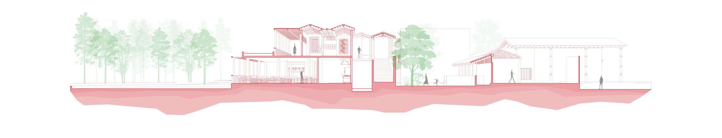
The Site is located in Chanapatna, a town that is famous for its Wooden Toy Industry, this art center has been designed for the local artisans to show off their skills and art to the general public. The Art center also keeps the theme of origin alive, by also acting like a natural museum showcasing how and what lead to the origins of the world famous Channapatna toys.
01
01
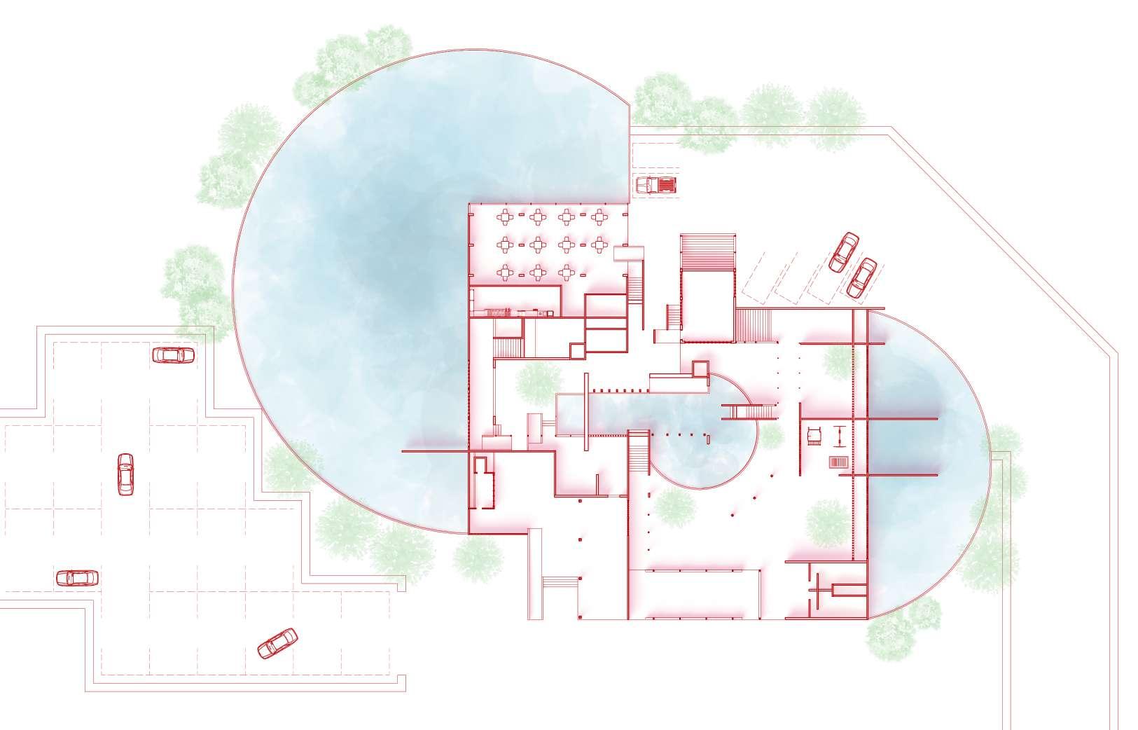
The art center comprises of the exhibition part which is the first part and later that of a public park, the design may look very randomly oriented but follows a path which will guide the people around the center. There are visual connections from one zone to the next of the journey to create a sense of curiosity for the people about what lies ahead. Water and green spaces are designed as a experiential element, i.e. they have been used to keep the user connected to nature. There is constant movement from open to semi open to closed spaces and vice versa.
Sidyathi Vana Art Center | 02
Ground Floor Plan (1:500)
First Floor Plan (1:500)
A A
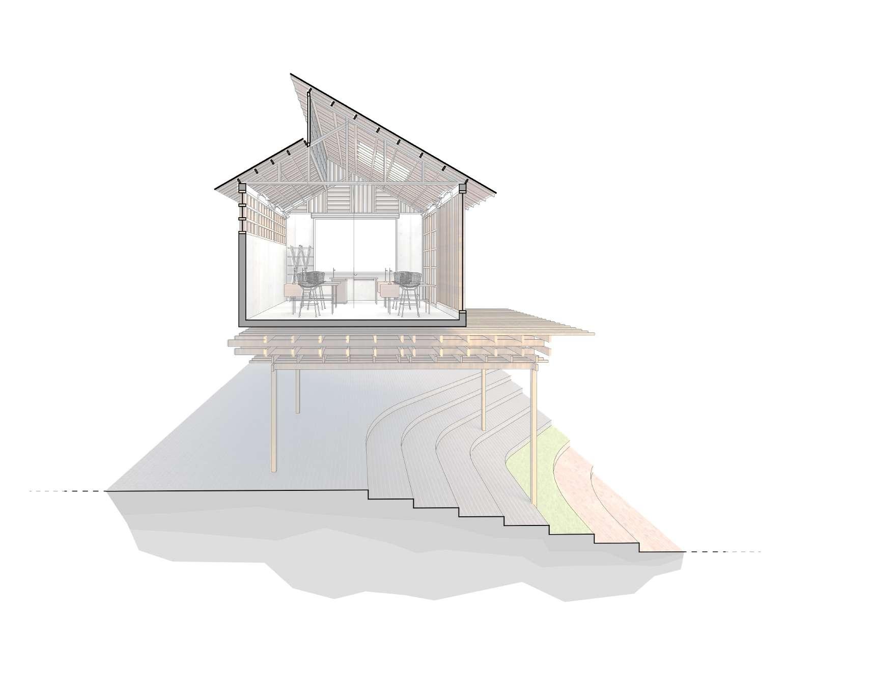
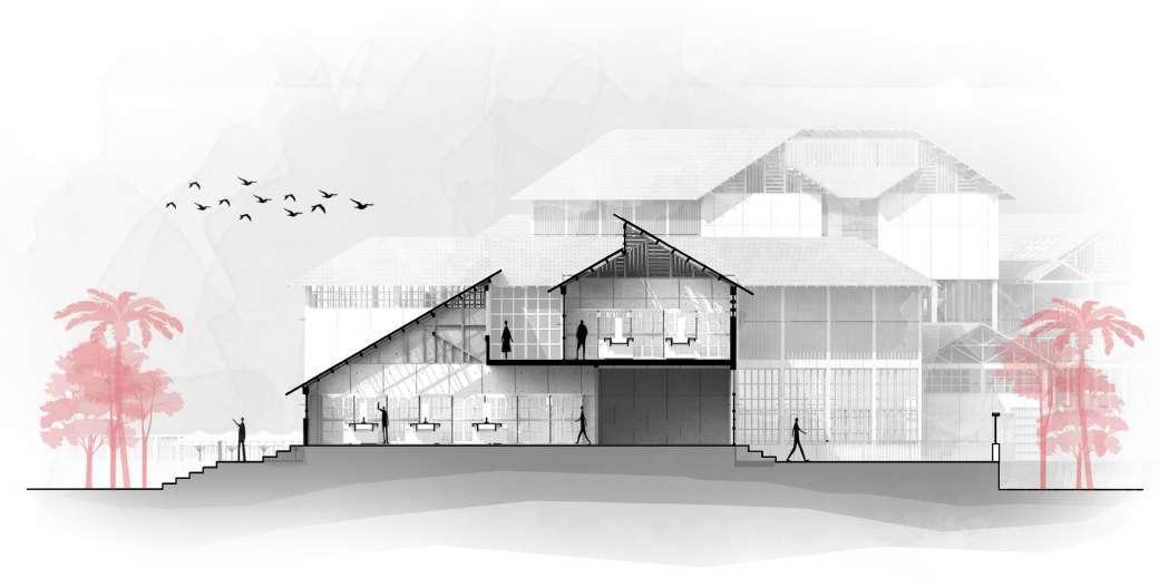
Section AA (1:250)
Sidyathi Vana Art Center | 03
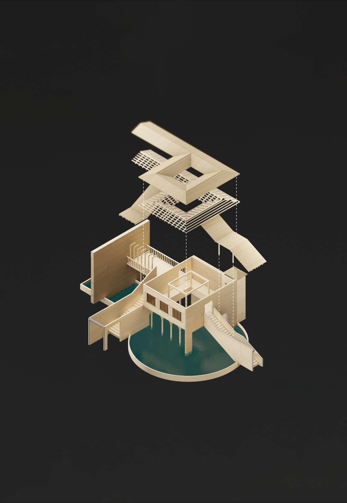
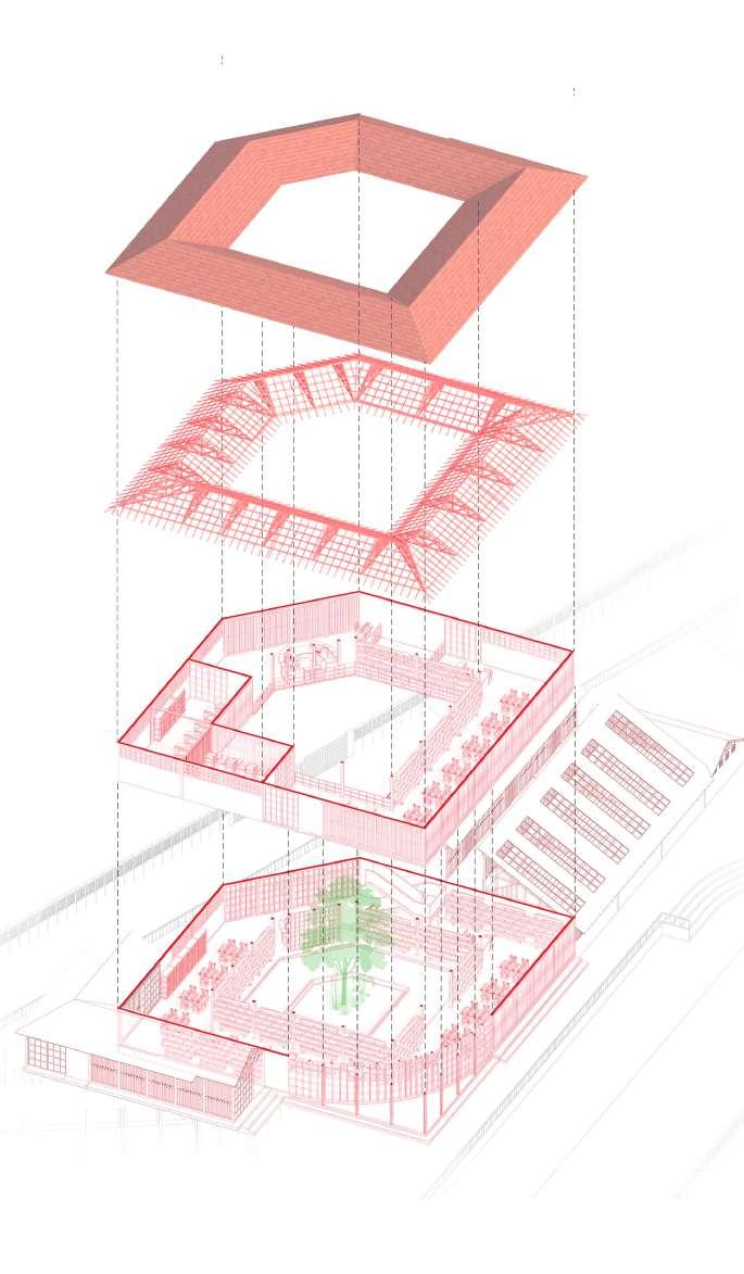
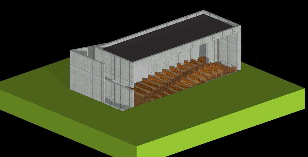
Exploded Axo of the Central Space in the Art Center
Entrance Stairs
Shade Structure
Roof Structure Brick Wall
Exit Stairs
Institutional Design 02
PRATHICHI SCHOOL OF EXPERIENTIAL LEARNING
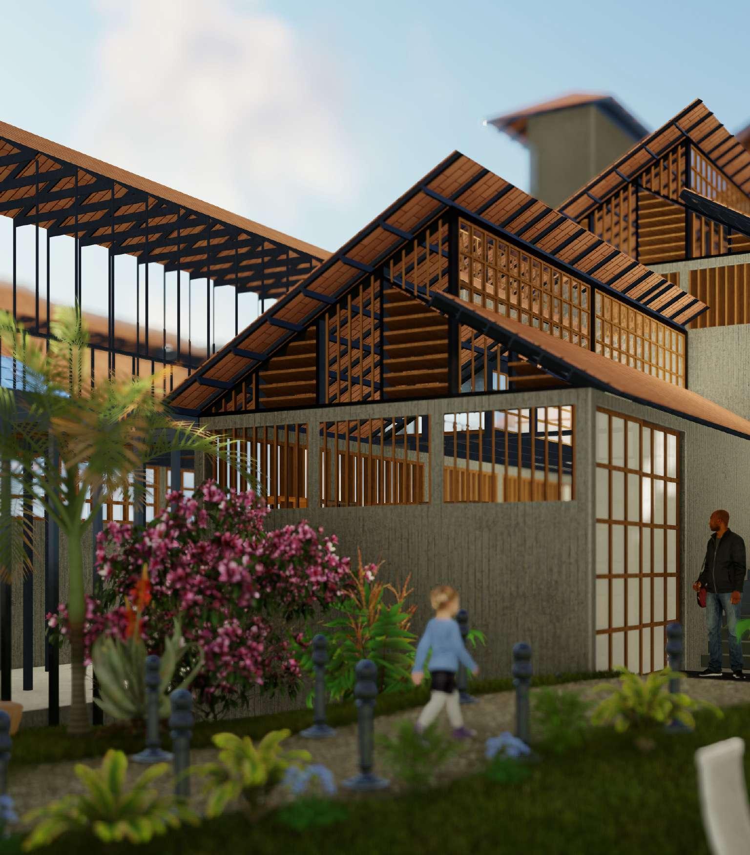
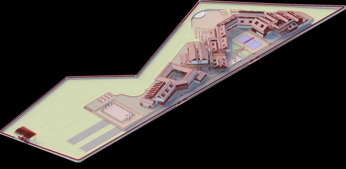
The Site is located in Hyderabad, the goal of this design studio was to break free from the norms set by the obligatory schooling in the country and design a space where students could learn in a different and a unique way. The school offers various opportunities for interactions for the students as classes are divided based on the subjects and the multitude of subjects available provide the students with more chances for academic achievements, and all this done by keeping the connection with nature alive.
04
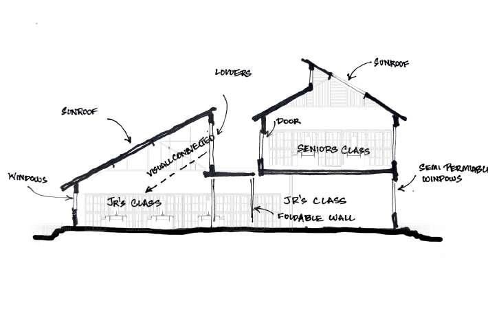
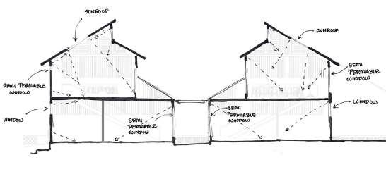
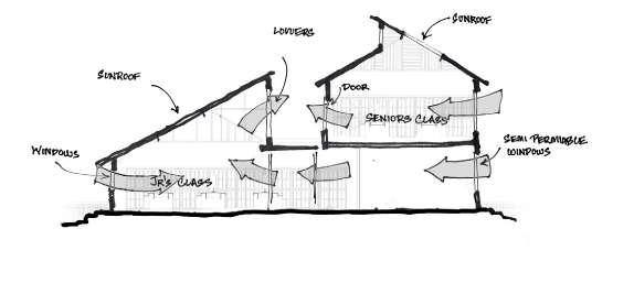
The Classrooms have been designed to have maximum interactions with the hopes that students will learn from one another during these interactions. The classes are separated based on subjects and classes take place simultaneously, hence the school remains active all the time. Two different classes will take place at the same time in the same building to promote learning from one another.
Prathichi School | 05
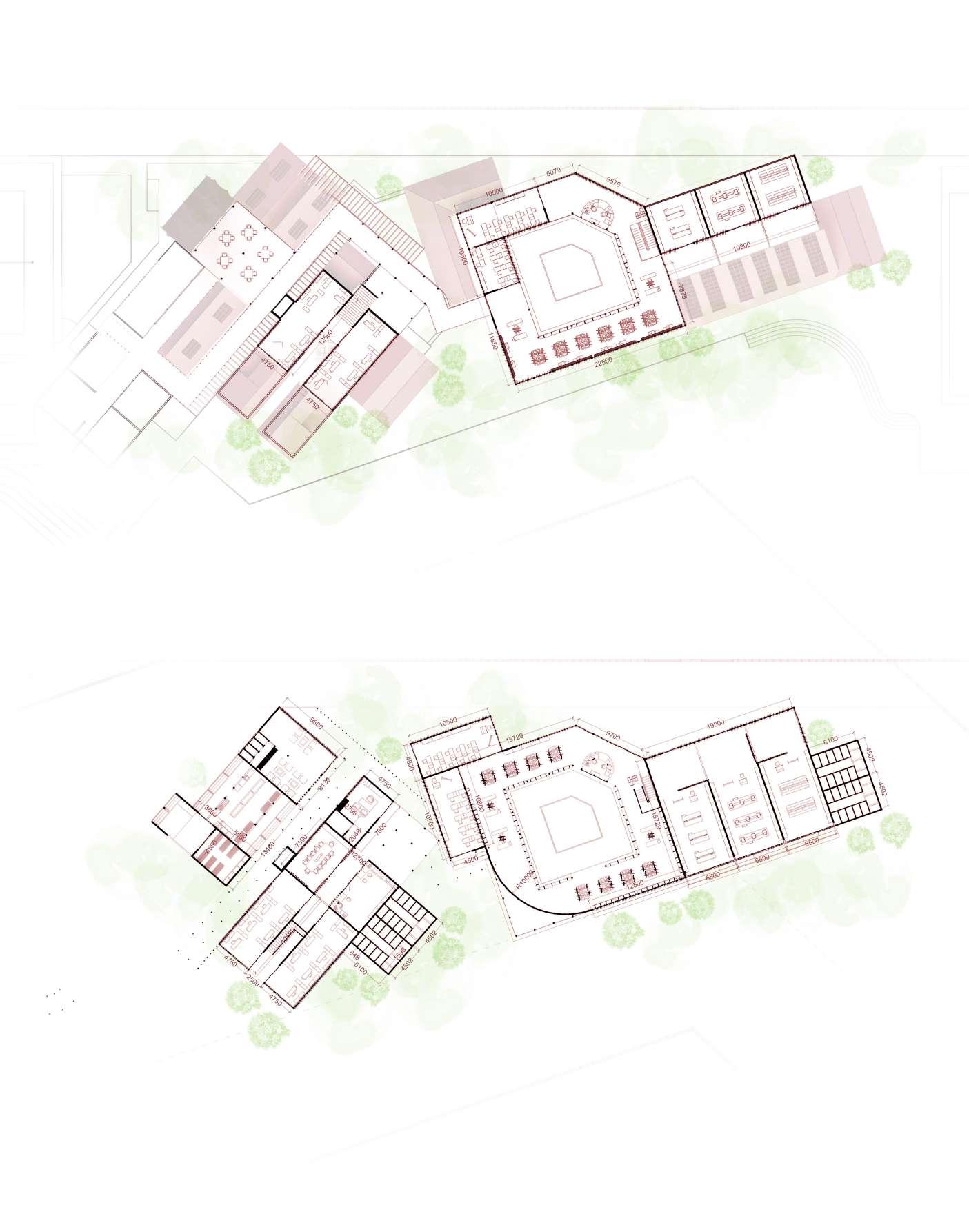
First Floor Plan
Ground Floor Plan
Isometric View (Key Plan)
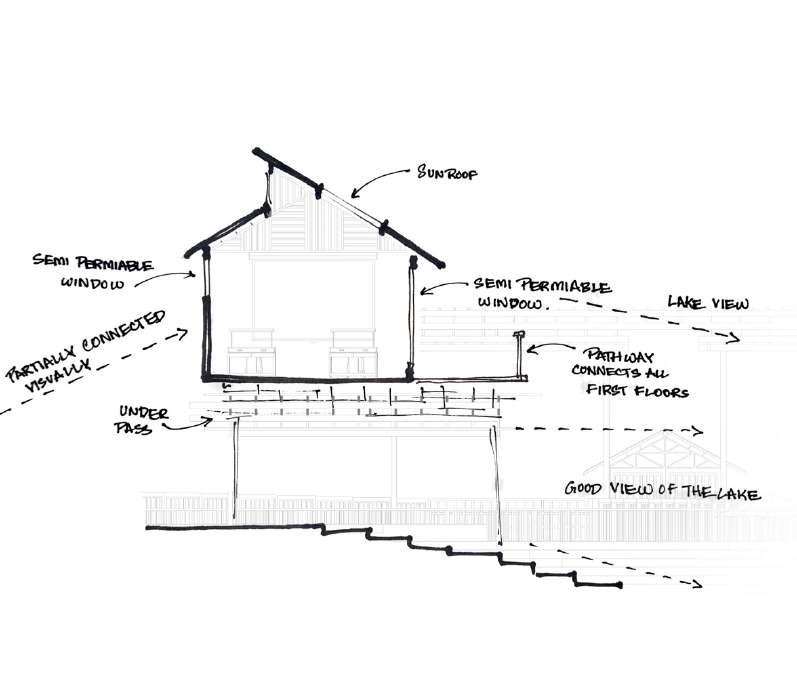
Sketch Showing the Visual Connection
A A A A
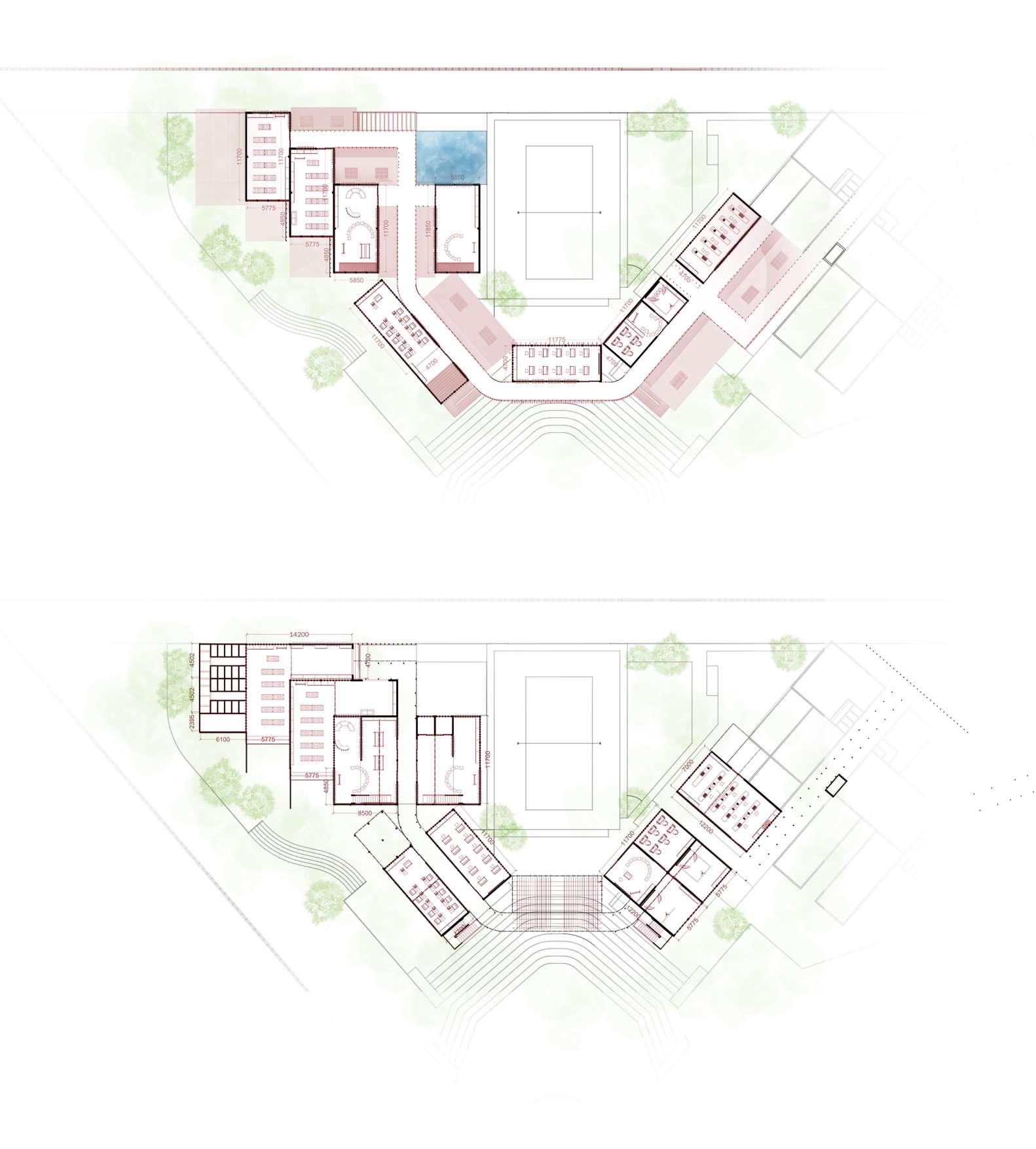
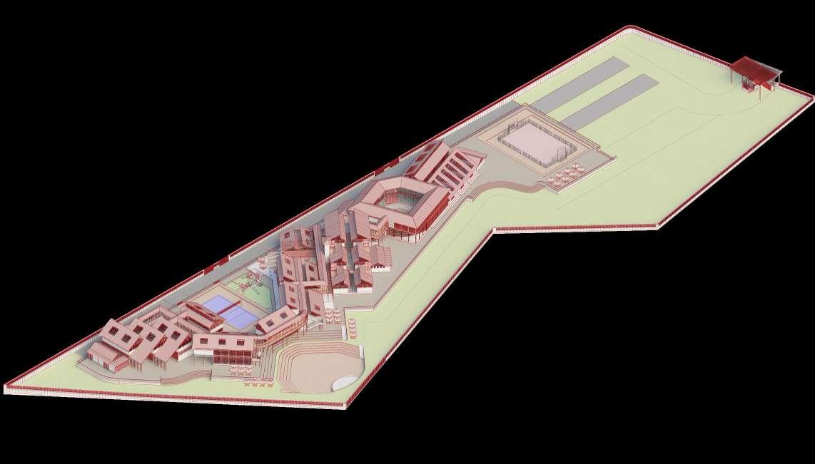
Prathichi School | 06 First Floor Plan Sun Set View Point Ground Floor Plan Isometric View (Key Plan) B B B B
All types of classes, irrespective of the subjects taught in them have prioritized connection with the outside, by providing large windows and openings, hence the classroom also has good natural lighting and ventilation.
Prathichi School | 07
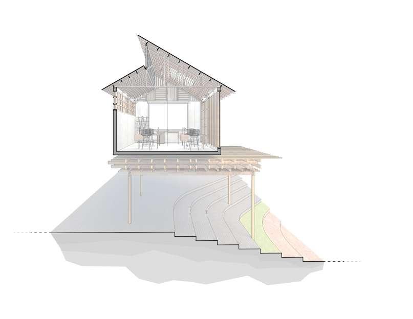
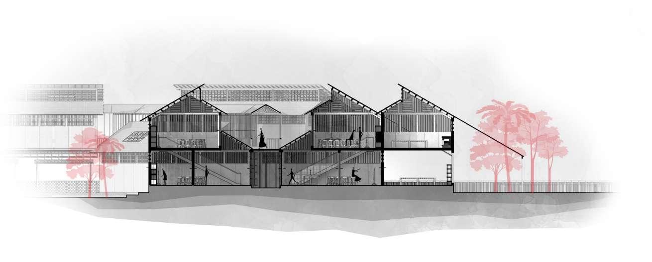
Section AA
Section BB
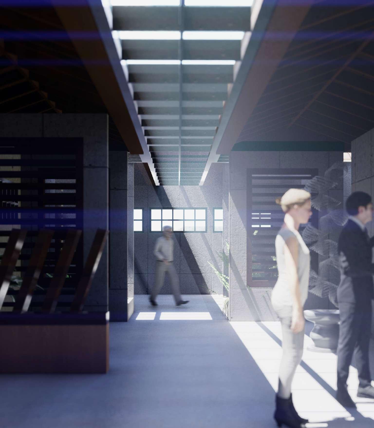
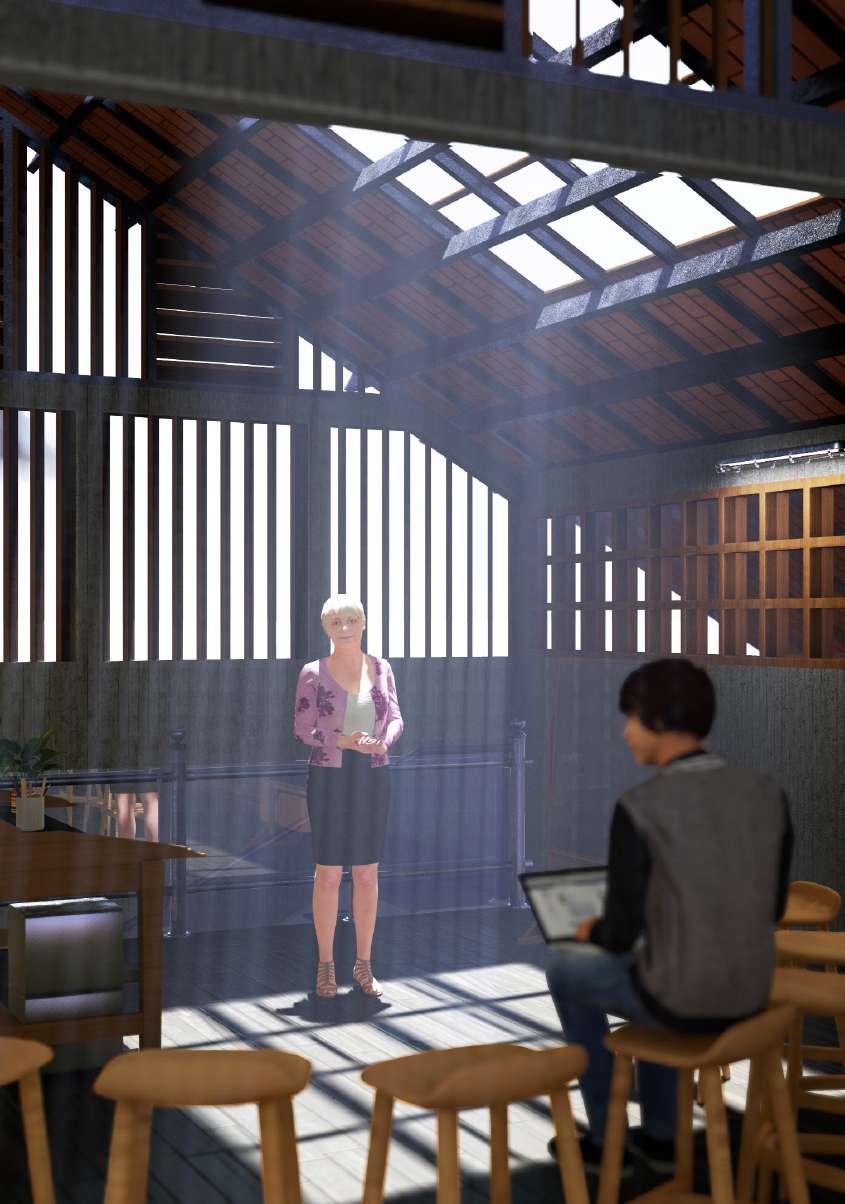
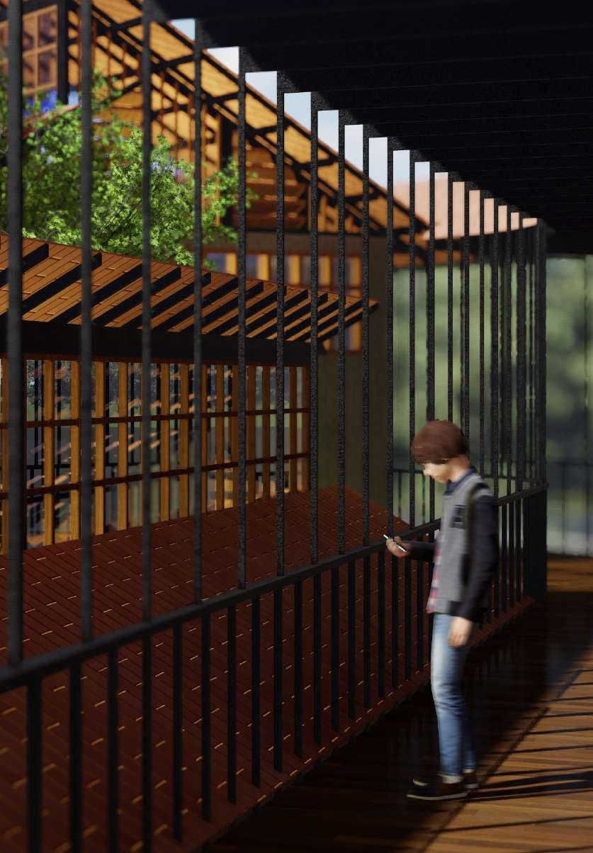
Inside View of a Classroom
Roof Structure
Roof Structure
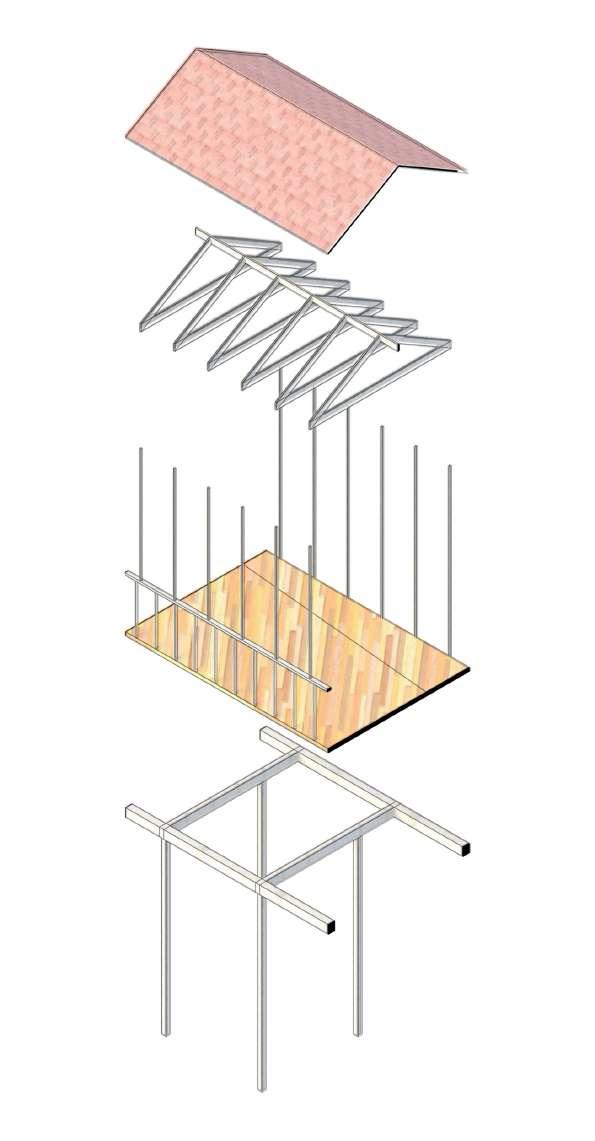
Library 1st Floor
Pathway
Library Ground Floor
Pathway Structure
Prathichi School | 08
Exploded Axo of the School Library
Exploded Axo of the Pathway Pathway Connecting all Senior Classrooms
Roof Tiles
Roof Tiles
Residential Design 03
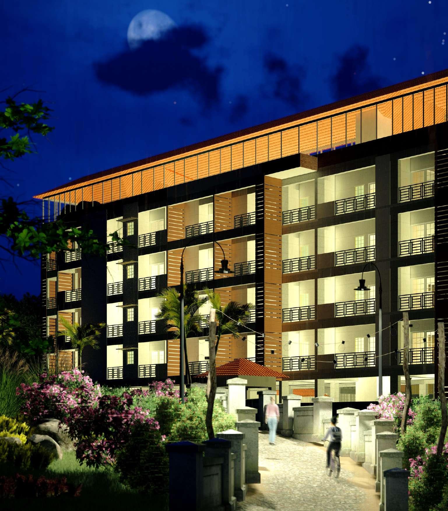
KARUH TINY HOUSING
The Site is located in Mangaluru city, more precisely in the industrial zone of the city. There is a high demand for rental houses by the trainees mostly bachelors and blue caller workers and marginal workers who are usually families of 3 or 4. The surrounding also isn’t well equipped with to house the current stack holders and hence a proposal for Micro Housing was devised for the location with the goal to house the people with low cost and highest economy of space.
09
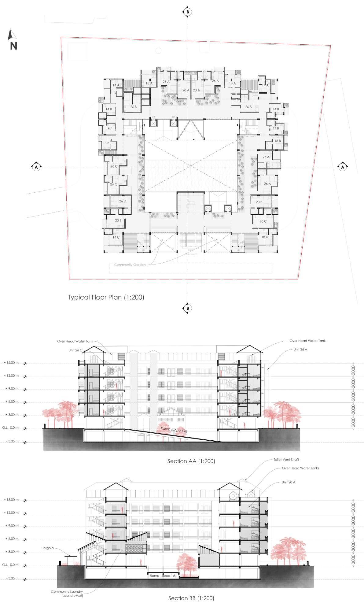
Ground Floor Plan (1:200)


Basement Plan Ground Floor Plan


The Basement has been designed to meet the parking requirements of the building but at the same time it also becomes an open courtyard and houses a green garden which creates opportunities for community development in the building and also become a recreational space for the tenants.
The ground floor again follows the similar principles as the basement plan and provides the tenants with large open gardens and pathways that brings nature into the building and provides a good recreational space for the users as well.
Karuh Tiny Housing | 10 4 m wide driveway 4 m wide driveway 3.75 m wide Ramp (1:8 slope) 3.75 m wide Ramp (1:8 slope) 1 2 3 4 5 6 7 8 9 10 11 12 13 14 15 16 17 18 19 20 21 22 23 24 25 26 27 28 29 34 35 36 37 30 31 32 33 1 2 3 4 5 6 7 8 9 10 R3500 R3500 R3500 R3500 Lift Lift Staircase 1 Lift Lift Staircase 1 Toilet Shaft Toilet Shaft Toilet Shaft Toilet Shaft UP UP N Basement Plan (1:200) 250 mm Retaining Wall Sump Tank 2.7 X 2.7 Sump Tank 2.7 x 2.7 6424 4960 3350 5080 5250 5250 3996 5250 5010 4835 6950 7000 7000 7000 6950 4835 STP Tank 2.7 x 2.7 STP Tank 2.7 x 2.7 4 m wide driveway 4 m wide driveway R3500 R3500 6000 38 39 40 41 42 43 44 45 46 47 48 49 50 51 63 11 12 13 14 Lift Lift Staircase 1 Down Toilet Shaft Toilet Shaft 3 m wide Pedestrian Access Only Up Up Staircase 3.75 m wide Ramp (1:8 slope) 3.75 m wide Ramp (1:8 slope) 1.5 m wide walkway Well (Water Source) Watchman Cabin 2000 x 2000 Transformer 5000 X 4500 Electrical Room 4700 4000 Utility 2500 x 4700 15 16 17 18 19 20 21 22 23 24 Basement Plan (1:200) Retaining Wall 4960 STP Tank 2.7 x 2.7 STP Tank 2.7 x 2.7 4 m wide driveway 4 m wide driveway R3500 R3500 R3500 R3500 6000 6 m wide two - way Vehicular Access 38 39 40 41 42 43 44 45 46 47 48 49 50 51 52 53 54 55 56 57 58 59 60 61 63 11 12 13 14 21 20 19 18 17 16 15 Lift Lift Staircase 1 Down Lift Lift Staircase 1 Down Toilet Shaft Toilet Shaft Toilet Shaft Toilet Shaft UP 3 m wide Pedestrian Access Only Up Up Staircase 2 Staircase 3 3.75 m wide Ramp (1:8 slope) 3.75 m wide Ramp (1:8 slope) 1.5 m wide walkway Well (Water Source) Watchman Cabin 2000 x 2000 Transformer 5000 X 4500 Electrical Room 4700 4000 Utility 2500 x 4700 62 1.5 m wide walkway Outdoor Pergola
Karuh Tiny Housing | 11
Section AA
Section BB
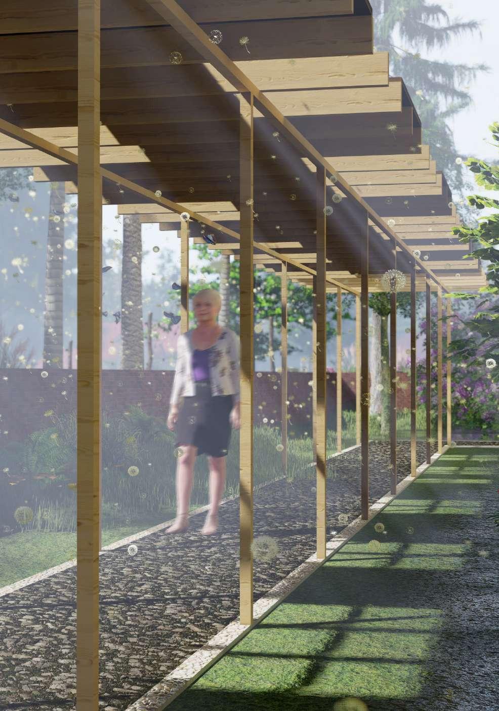
Pergola’s in Walkways
Typical Floor Plan
The southern facade has been used as a space to provide community gardens for the tenants to grow vegetables and fruits for daily use and for public spaces such as the community laundry space etc, the staggering of the units was to achieve ventilation and provide privacy to the tenants without lose in space.
Note: Unit Design Credit - Chirag JK | Sem 4
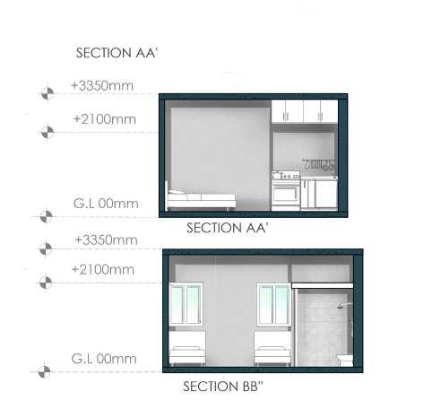
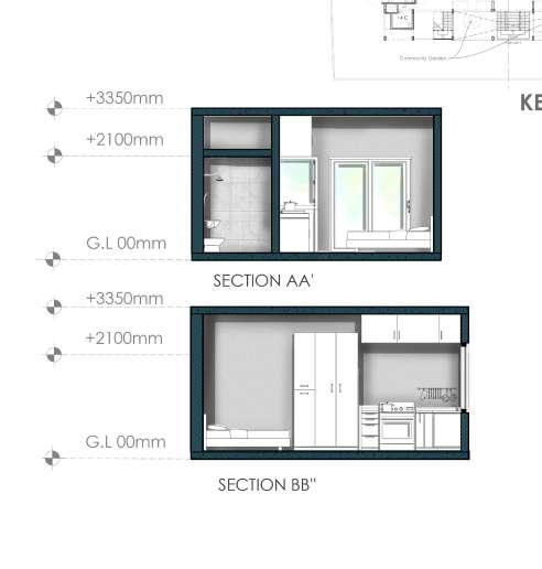
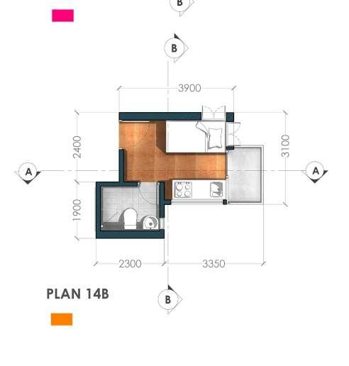
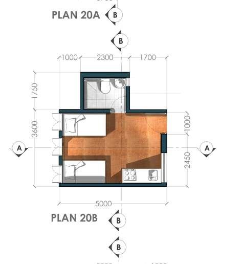
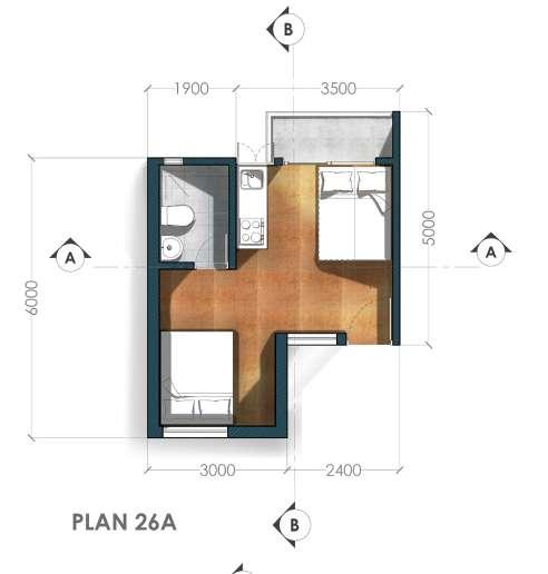
Karuh Tiny Housing | 12
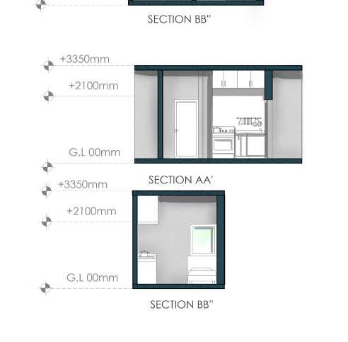
Unit Plan 26A
Section BB’
Section BB’
Section BB’
Section AA’
Section AA’
Section AA’
Unit Plan 20B
Unit Plan 14B
Urban Design
THE GREEN REVIVAL
The Urban Intervention was focused on the city of Mangalore, located in the west coasts of India, in the state of Karnataka. The studio was aimed to design an intervention focused around the concept of water. The city is located on the mouth of two major rivers, the Netravathi River and the Gurupura River, and receives an surplus amount of rain fall every year during the monsoons, and still faces a lot of problems related to water. We specifically choose the site of Bikampady as our location as it is the Industrial Zone of the city.
13
04
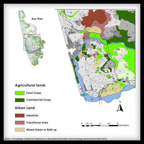
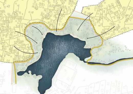
The location had major lakes and large amounts of agricultural lands, and the locals were majorly dependent on ground water for sustenance. The small streams also brought in a lot of aquatic life which became a source of food for the people. This is no more the case, people aren’t able to continue the normal fishing activities in those streams, the lakes have been polluted and has been cut off from public access and ground water has also started getting polluted. The reason for all these problems is the sudden growth of industries and bad infrastructure and waste management by the corporate companies.
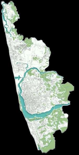
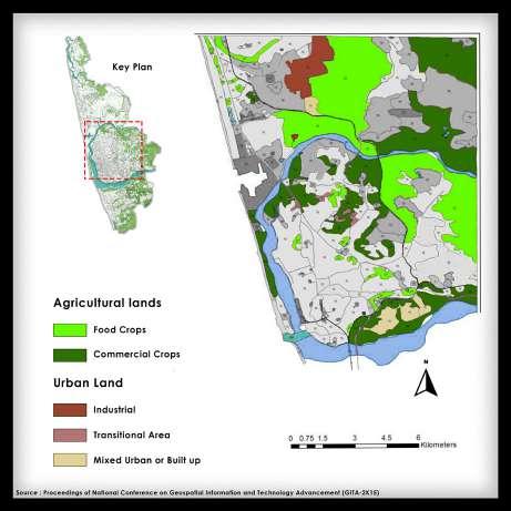
Amendment of the land reform act together with low yield and heavy rainfall in the years 1971 - 2001 forced the farmers to sell their lands to corporates and Industries. This becomes evident when the land-use map 2003 is compared with the land-use map of 2013. The decrease in agricultural lands is significant and the rise of the industries is very clear.


The Industrial Area has proposed a buffer zone of 2km around the major industries and ideally they say its better for no residences to be present in this area, and the existing residences have to deal with the consequences of the presence of the industries. This isn’t a very practical approach towards the growth of industries, also the previously owned agricultural land can be easily acquired and the any existing buildings can be evicted.
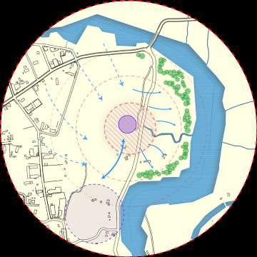

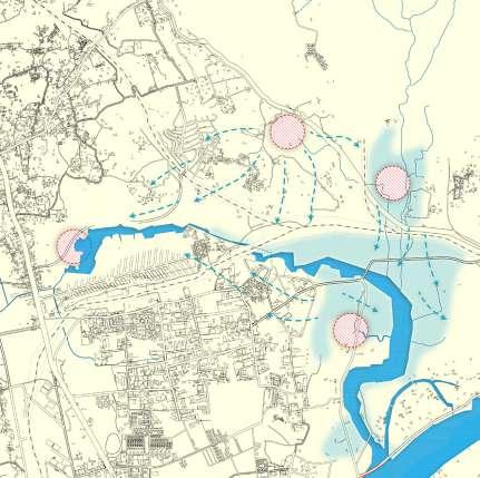
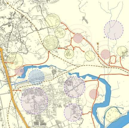
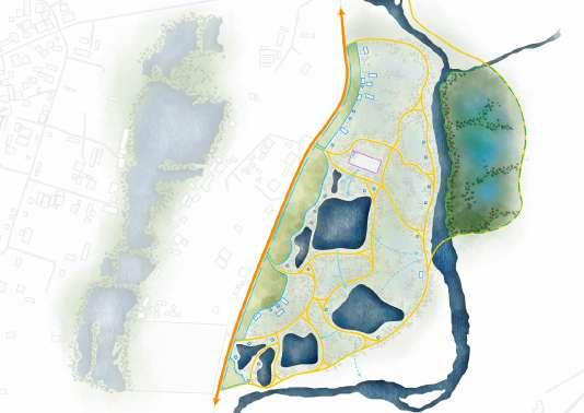
4 sites were choose for each of these sites was contributing majorly in the pollution of the ground water for the surrounding people. Site 1 used to be a major aquifer, which has now succumbed to uncontrolled digging and mining. Site 2 was a temple lake, which was the source of water for the agricultural lands of the temple and now has been completely polluted. Site 3 used to be a major lake and a recharge point for many aquifers and also has been polluted. Site 4 is a stream connected to the river which was the source of the food for the localities and now has become a hub for toxic waste. These sites are one of the major points of recharge for the aquifers and can be used to purify the already polluted ground water as they also will work with one another and help in recharging and clearing out the groundwater for a larger area. These spots also can become the buffer zones that are needed in industrial zones rather than a boundary buffer.
The Green Revival | 14 NMPT Property School K.S.P.B. MSEZ Colony Temple Temple Temple Tokuru Railway Station School School MRPL HPCL Bikampady Industrial Zone Krishna Nagara School And Mosque Mosque School And Church
Mangalore: Bikampadi
Land Use Map 2003
Karnataka Site 1 Site 1 Site 3 Site 3 N Site 2 Site 2 Site 4 Site 4 Site 1 Site 2 Site 3 Site 4 200 m 200 m 200 m 200 m
Land Use Map 2013
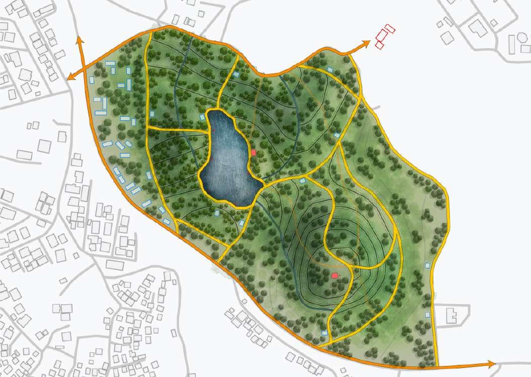
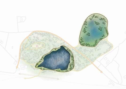
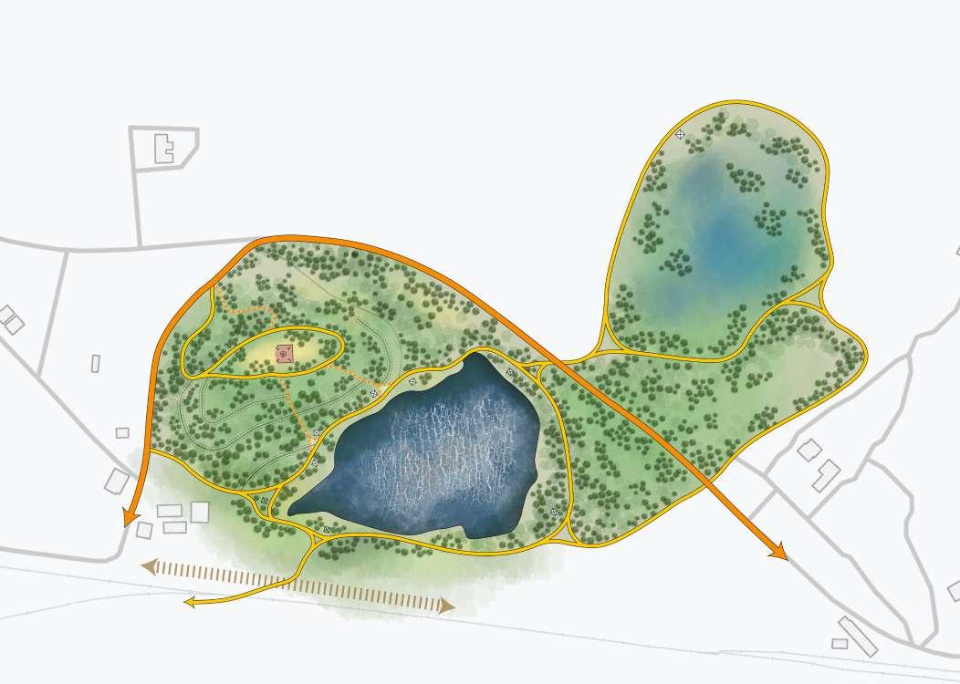
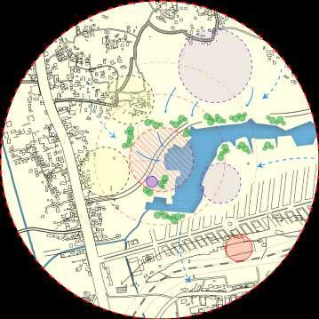
The Green Revival | 15 Site 2: Connecting the local communities and the temple to the lake again.
2: Catchment zone used to developed a new ecosystem and to create an active recharge point 400 400 01 02 03 Site 1: Site 2: Site 2: Site 1: 01 03
02 400 400 N 0 50 100 200 01 02 03 Existing Roads/Paths Proposed Roads/Paths Storm Water Drains Footpaths Existing School Water Quality Monitoring System Air Quality Monitoring System Local Merchants Water/Air Quality Monitoring Unit Points of Interest 01 02 03 Existing Roads/Paths Proposed Roads/Paths Storm Water Drains Footpaths Existing Temple Catchment Zone For Wetland Development Tokkur Station Local Merchants Water Quality Monitoring Unit Points of Interest N 0 50 200 100
Site
Site 1: Bringing in local merchants to sustain the park and making the school accessible. Site 1: Intervention aims to rejuvenate the newly created lake because human intervention.
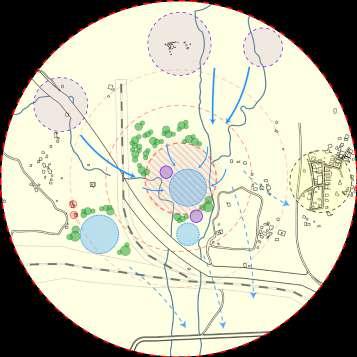
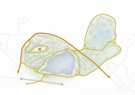
Site 3: Connecting the Lake to the nearby localities, keeping the lake alive
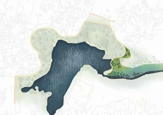
Site 3: The Catchment zone is a good recharge point and a hub for wildlife
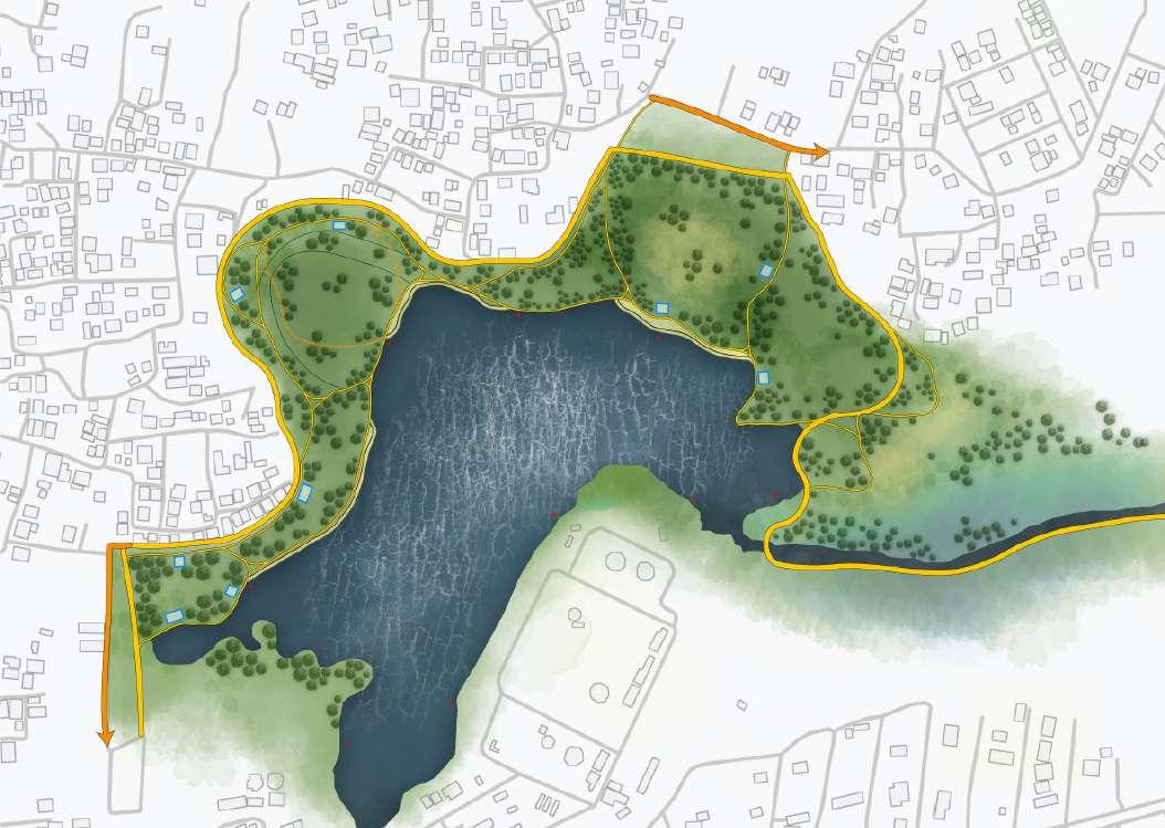
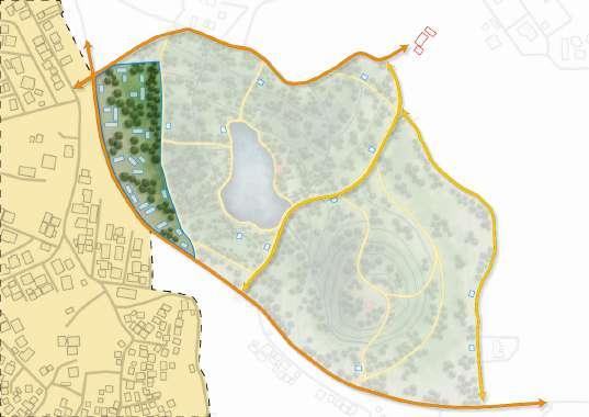
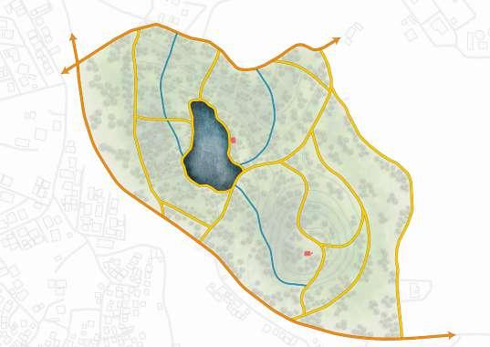
Site 4: Using Catchment areas as Harvesters for the Industries to use that water.
Site
The Water Treatment Plant creates a small water ecosystem in the area.
The Green Revival | 16
4:
01 01 02 02 02 02 03 04 02 04 03 400 400 400 400 01 02 03 04 Existing Roads/Paths Proposed Roads/Paths Storm Water Drains Footpaths Water Treatment Plant Commercial zone/ Parking Water Harvesters/ Catchment Zones Catchment Zone For Wetland Development Local Merchants Water Quality Monitoring Unit Points of Interest Site 4: Site 4: Site 3: Site 3: N 0 50 100 200 01 02 03 04 Existing Roads/Paths Proposed Roads/Paths Storm Water Drains Footpaths Existing Paddy Farms Open Air Ground to Play Open Air Ground for Gatherings Catchment Zone For Wetland Development Local Merchants Water Quality Monitoring Unit Points of Interest N 0 50 100 200
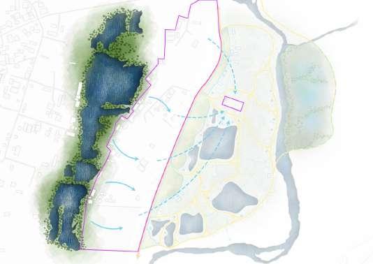
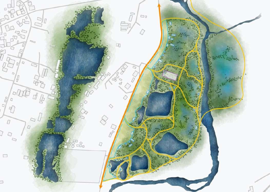
Based on the sites we devised an intervention and came up with 4 prototypes which can be applied in appropriate locations around the 4 sites.
Prototype 1:
Mainly designed to help recharge the aquifers at the different sites, mainly site 1 and 2 as they are located on a hilly terrain and have large storm water runoffs.
Prototype 2:
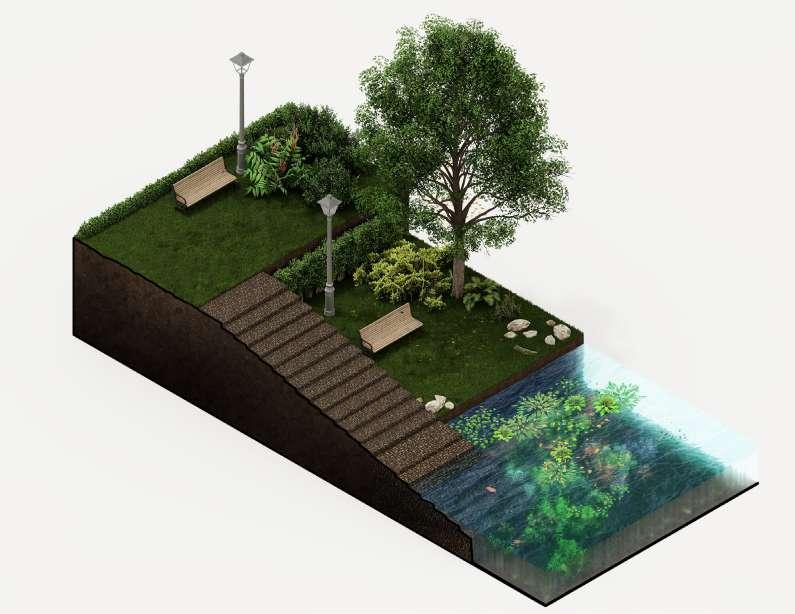
Designed for the large catchment areas on the sites to clear out the natural storm water using wetland plants and create new recharge points for the aquifers.
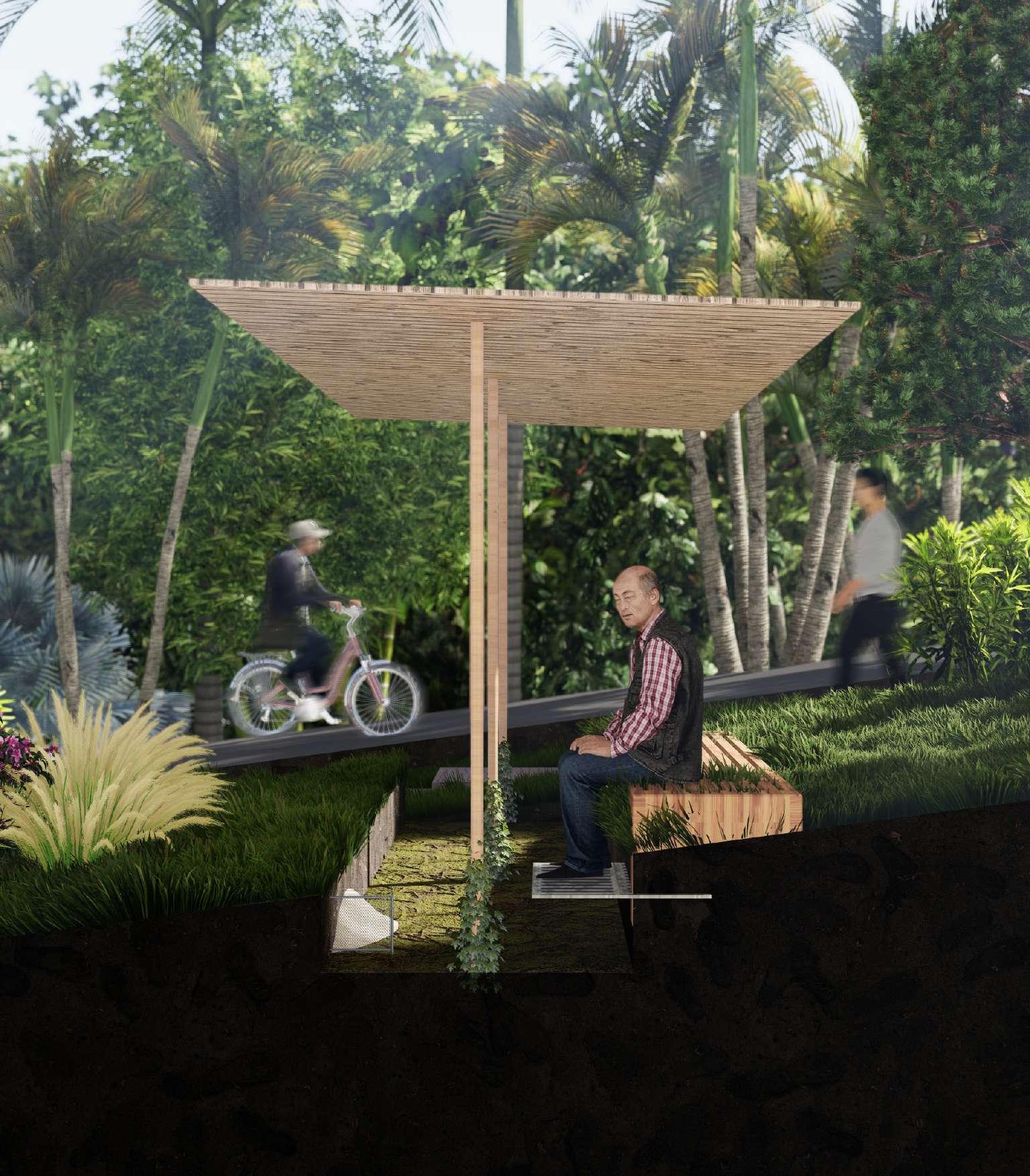
Prototype 3:
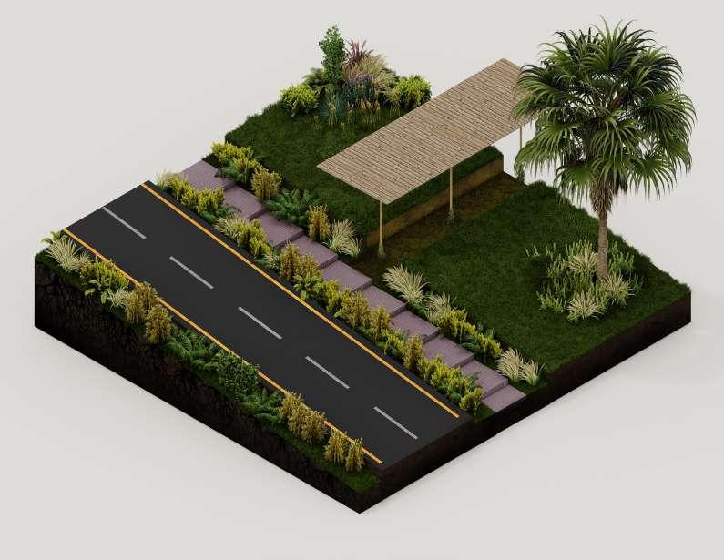
Designed to work along the pathways created near the river streams as a way for the people to access the water and connect them back to the water body invoking a local temple tanks design.
Prototype 4:
The monitoring stations that work in accordance with the existing bodies of law monitoring the water contamination and toxicity levels.
The Green Revival | 17
Prototype 1
Prototype 3
Prototype 2
Prototype 4
Commercial Design
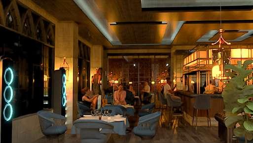
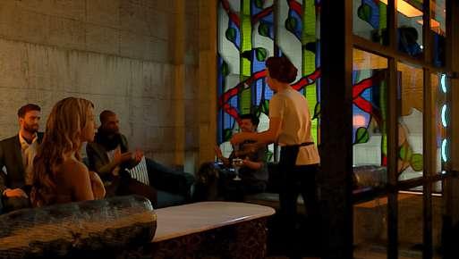
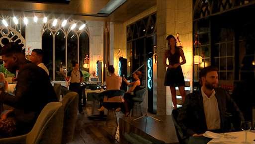
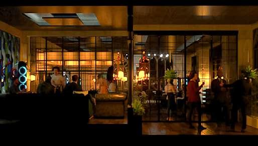
NIGHT LIGHT RESTO
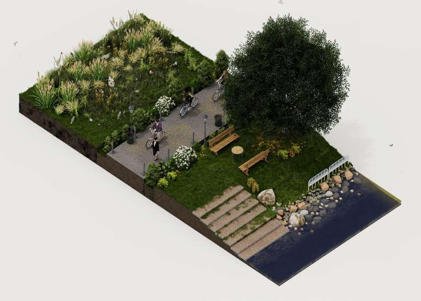
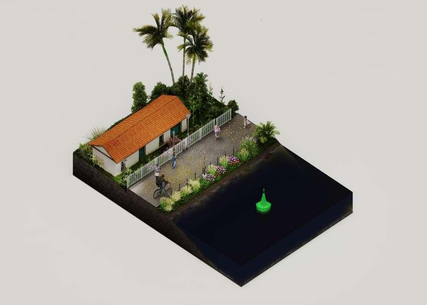
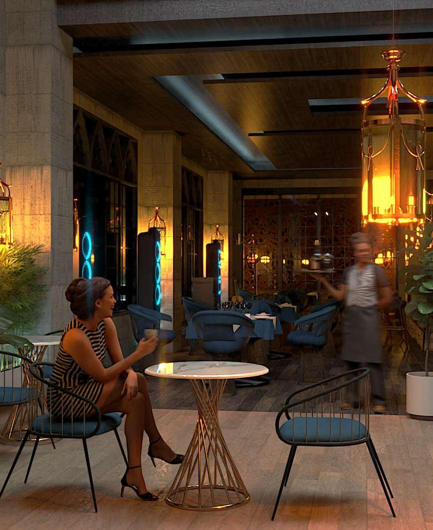
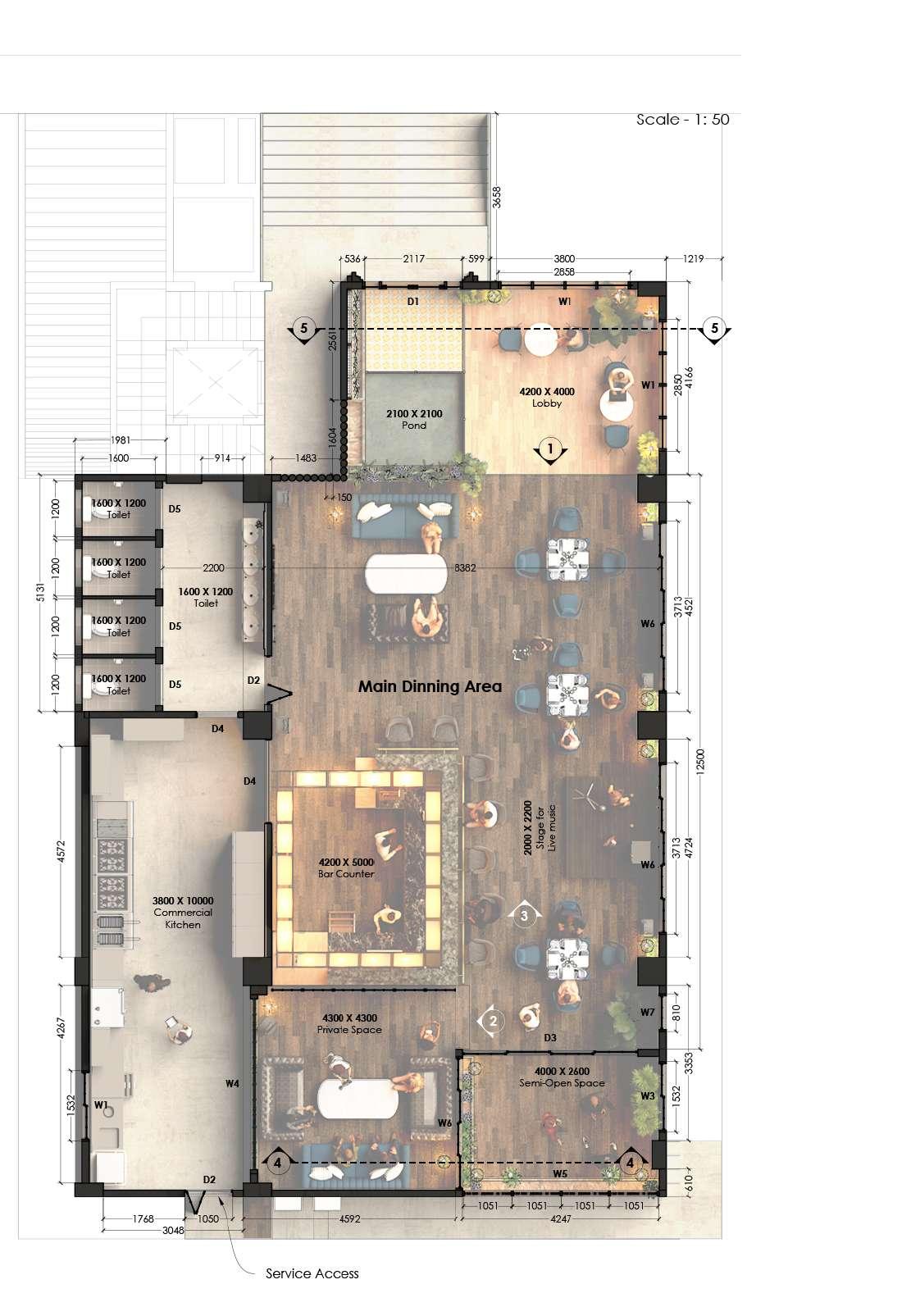
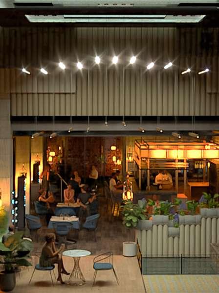
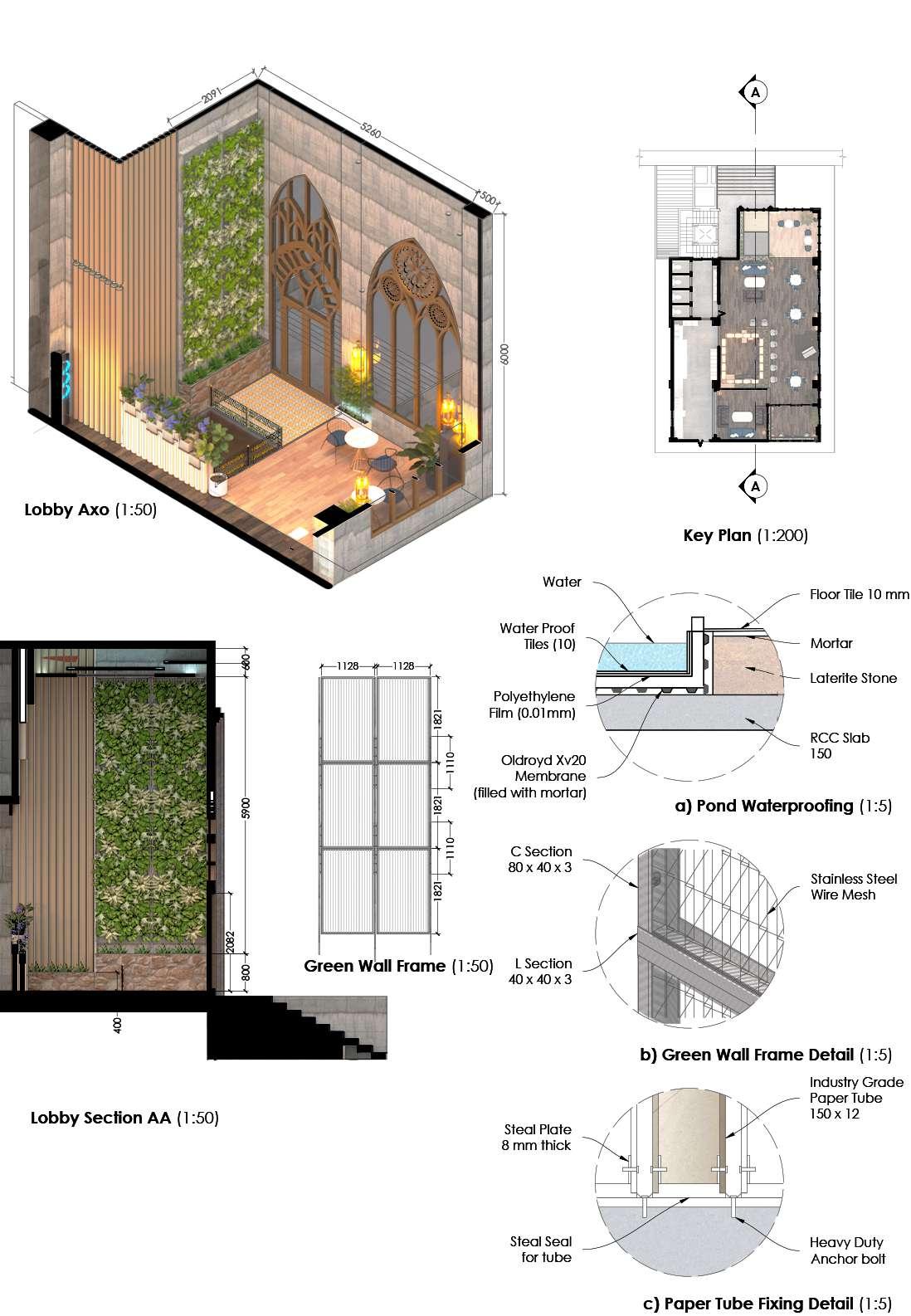
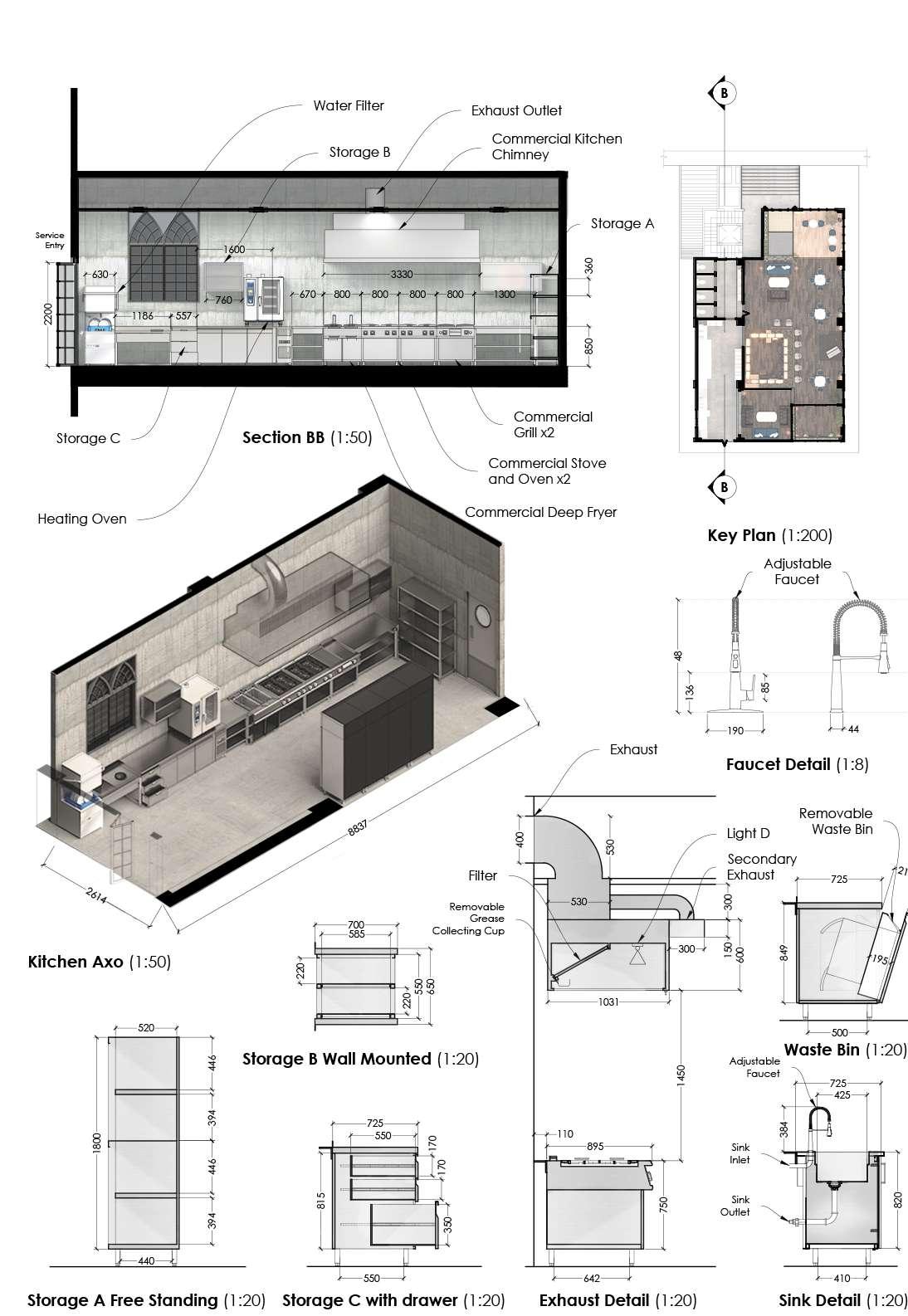
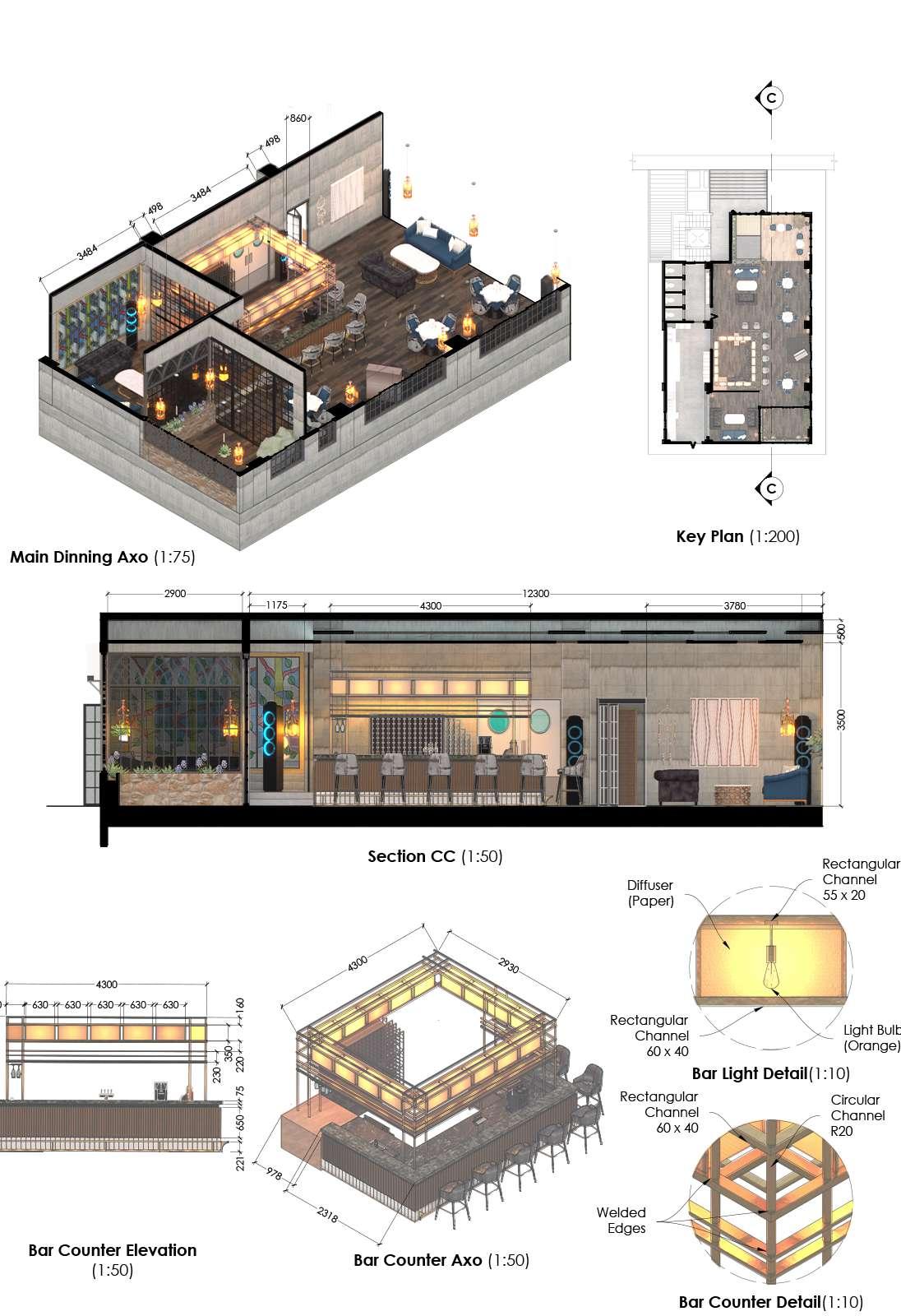
The cafe/restaurant is located in Mangaluru city, the requirements presented for the design was to create an ambient environment with a dark theme, but by using pastel colors. The client wanted to include a small water body in the cafe and have a sense of openness and not have any form of separation at the same time maintaining a sense of privacy. The client also wanted to integrate nature and live music into the design and specifically requested for arched openings.
18
05
Night Light Resto | 19
View 1
View 2
View 3
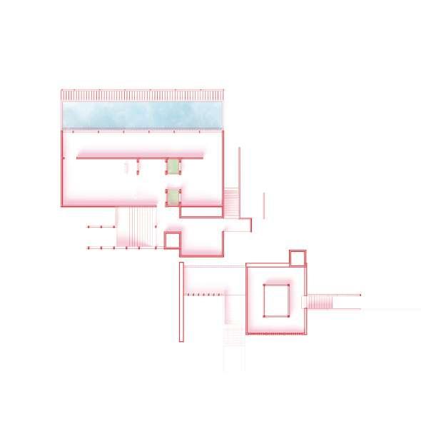
Cafe Plan
View 4
View 5
Night Light Resto | 20
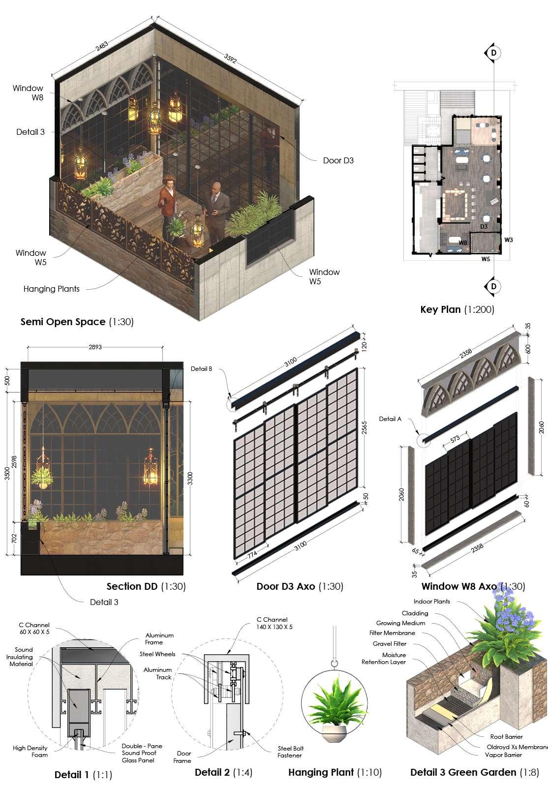
Night Light Resto | 21
Technical Drawings
These are some of the technical drawings that were drafted by me, note that the drawings have been resized from A2 size to A4 without taking into the scales mentioned in the drawings. The software used to draft all the drawings was AutoCad by AutoDest and for some of the sheets I have done some post-production work on Photoshop.
22 1755 1278 2241 3385 1701 3321 front 0 2 note: all dimentions are in mm 4 A b c d e 3 1 5 7 4 front porch up 2 6 1 skanda vrishank v nu18uar033 b.arch 5th sem nitte institute of architecture center line plan; Ground floor working drawing sheet no: 01 13681 10708 f 3384 1521 925 994 3884 study 3154 X 2749 living room/dinning room 5578 X 6134 kitchen 4675 X 3155 pooja 1291 X 1219 bedroom 4674 X 3764 w.c. 1689 X 2049 Duplex Centerline Ground Floor Plan
Duplex Ground Floor Plan Duplex First Floor Plan
23 study 3154 X 2749 living room/dinning room 5578 X 6134 kitchen 4675 X 3155 pooja 1291 X 1219 0 2 note: all dimentions are in mm 4 1 skanda vrishank v nu18uar033 b.arch 5th sem nitte institute of architecture ground floor plan working drawing sheet no: 05 1755 1278 2241 3385 1701 3321 front A b c d e 3 1 5 7 4 front porch 2 6 13681 10708 f bedroom 4674 X 3764 w.c. 1689 X 2049 3384 1521 925 994 3884 1521 1521 1521 1521 910 1521 1521 776 1521 1521 910 1071 up 1286 1730 1208 533 651 578 3155 eql. eql. 1219 1291 3154 651 833 578 4675 837 799 4675 2247 1104 1140 1595 1560 2855 eql. eql. 2049 2372 1954 655 929 1027 2593 910 910 760 a a b b kitchen counter w1 w4 w1 w1 w3 w1 w2 w6 w2 w1 d2 d2 d4 d1 d3 schedule for windows sill ht. window lintel ht. 300 1 2100 650 2 2100 300 3 2100 900 4 2100 1500 5 2100 650 6 2100 schedule for windows door lintel ht. 1 2100 2 2100 3 2100 4 2100
0 2 note: all dimentions are in mm 4 1 skanda vrishank v nu18uar033 b.arch 5th sem nitte institute of architecture first floor plan working drawing sheet no: 06 A b c d e f 3 1 4 2 5 down 1755 2241 3385 2944 10289 10708 balcony 10478 X 2749 living room/dinning room 5573 X 4294 3384 1521 925 994 3884 1521 1521 760 front up gym 4675 X 3155 bedroom 4674 X 3764 w.c. 1689 X 2049 930 1521 1521 1521 1521 910 1979 770 651 651 1521 837 799 4675 2247 1104 1140 1595 1560 2855 eql. eql. 2049 910 910 eql. eql. 3653 655 2576 1595 1558 776 910 776 786 752 752 821 770 2246 1000 2448 2248 1000 798 837 b b w1 w3 w3 w1 w2 w2 w6 schedule for windows sill ht. window lintel ht. 300 2100 650 2 2100 300 3 2100 900 4 2100 1500 5 2100 650 6 2100 a a w2 w5 d3 d2 d2 d4 schedule for windows door lintel ht. 2100 2 2100 3 2100 4 2100
Steel Staircase: Straight Flight
Steel Staircase: Dog Leg

24 A a b 10mm thick plate 8mm dia "u" foundation bolt 120 x 80 x 5 rec. hollow pipe 10mm thick plate concrete bed 80 x 80 x 3.6 squ. hollow pipe 8mm dia bolts ismb 150 8mm dia bolts 10mm thick base plate 100 x 160 C CHANNEL 20 x 20 x 2 squ. hollow pipe 1200 300 6075 6075 3000 100 x 160 C CHANNEL 75 X 55 rec. hollow pipe 20 x 20 x 2 squ. hollow pipe 1575 b 1200 475 C b a detail b 1:5 detail c 1:5 detail a 1:5 note: all dimensions are in mm 1 2 3 4 5 6 7 8 9 10 11 21 20 19 18 17 16 15 14 13 12 11 A A' 3783 2720 1200 1200 first floor plan 1:30 20 x 20 x 2 squ. hollow pipe 1180 landing platform 2720 x 1180 120 x 80 x 5 rec. hollow pipe section aa' 1:30 20 x 20 x 2 squ. hollow pipe 80 x 80 x 3.6 squ. hollow pipe 20 x 20 x 2 squ. hollow pipe a 3000 note: all dimensions are in mm ismb 150 8mm dia bolts 10mm thick base plate 120 x 80 x 5 rec. hollow pipe 20 x 20 x 2 squ. hollow pipe 10mm thick plate 8mm dia "u" foundation bolt 120 x 80 x 5 rec. hollow pipe 10mm thick plate concrete bed 80 x 80 x 3.6 squ. hollow pipe 8mm dia bolts 10 mm thick synthetic slab 10 mm thick steel casing 120 x 80 x 5 rec. hollow pipe 10 mm thick synthetic slab 120 x 80 x 5 rec. hollow pipe B D C detail a 1:5 detail b 1:5 detail c 1:5 detail d 1:5 150 100 10mm thick plate concrete bed 80 x 80 x 3.6 squ. hollow pipe 8mm dia bolts detail c 1:5
Truss Design and Detailing Steel Staircase: Spiral Staircase
25 detail a G.L. G.L. 180 MM OUTER DIA 4.8 MM THICK CIRCULAR HOLLOW PIPE 180 MM OUTER DIA 4.8 MM THICK CIRCULAR HOLLOW PIPE 180 MM OUTER DIA 4.8 MM THICK CIRCULAR HOLLOW PIPE 20 MM THICK STEEP PLATE 50 X 70 X 4 SQU. HOLLOW PIPE 8MM DIA. STEEL ROD 20 MM DIA. HOLLOW STEEL PIPE detail A 1:4 PLAN 1:25 Front elevation 1:25 right elevation 1:25 Isometric view 1:25 3150 3150 detail a 1:8 detail B 1:8 detail C 1:8 sectional view of the truss 1:20 KEY Plan 1:200 detail c detail b detail A 2 ISA 6040 6 mm thick 2 ISA 6040 6 mm thick 2 / ISA 6545 8 mm thick 150 X 100 X 10 rEC. hOLLOW pIPE 10 MM THICK gUSSET pLATE 2 / ISA 6545 8 mm thick 2 / ISA 6040 6 mm thick 2 / ISA 6040 6 mm thick 10 MM THICK gUSSET pLATE welded JOINTS 2 / ISA 8050 8 mm thick 4975 4975 4975 4975 12000 2 / ISA 8050 8 mm thick 2 / ISA 6545 8 mm thick 10 MM THICK gUSSET pLATE iSA 15075 6 MM THICK 150 X 100 X 10 rEC. hOLLOW pIPE 16 MM DIa Lewis bolt Pcc 18° iSA 15075 6 MM THICK 2 / ISA 8050 8 mm thick 10 MM THICK gUSSET pLATE 2 / ISA 6040 6 mm thick detail a 1:8 detail B 1:8 detail C 1:8 sectional view of the truss 1:20 KEY Plan 1:200 detail c detail b detail A 2 / ISA 6040 6 mm thick 2 / ISA 6040 6 mm thick 2 / ISA 6545 8 mm thick 150 X 100 X 10 rEC. hOLLOW pIPE 10 MM THICK gUSSET pLATE 2 / ISA 6545 8 mm thick 2 / ISA 6040 6 mm thick 2 / ISA 6040 6 mm thick 10 MM THICK gUSSET pLATE welded JOINTS 2 / ISA 8050 8 mm thick 4975 4975 4975 4975 12000 2 / ISA 6545 8 mm thick 10 MM THICK gUSSET pLATE iSA 15075 6 MM THICK 150 X 100 X 10 16 MM DIa Lewis bolt Pcc 18° iSA 15075 6 MM THICK 2 / ISA 8050 8 mm thick 10 MM THICK gUSSET pLATE 2 / ISA 6040 6 mm thick 1 2 3 4 5 6 7 8 9 10 11 21 20 19 18 17 16 15 14 13 12 11 A A' 3783 2720 1200 1200 first floor plan 1:30 20 x 20 x 2 squ. hollow pipe 1180 landing platform 2720 x 1180 120 x 80 x 5 rec. hollow pipe section aa' 1:30 20 x 20 x 2 squ. hollow pipe 80 x 80 x 3.6 squ. hollow pipe 20 x 20 x 2 squ. hollow pipe a 3000 note: all dimensions are in mm ismb 150 8mm dia bolts 10mm thick base plate 120 x 80 x 5 rec. hollow pipe 20 x 20 x 2 squ. hollow pipe 10mm thick plate 8mm dia "u" foundation bolt 120 x 80 x 5 rec. hollow pipe 10mm thick plate concrete bed 80 x 80 x 3.6 squ. hollow pipe 8mm dia bolts 10 mm thick synthetic slab 10 mm thick steel casing 120 x 80 x 5 rec. hollow pipe 10 mm thick synthetic slab 120 x 80 x 5 rec. hollow pipe B D C detail a 1:5 detail b 1:5 detail c 1:5 detail d 1:5 150 100 10mm thick plate concrete bed 80 x 80 x 3.6 squ. hollow pipe 8mm dia bolts detail c 1:5
26
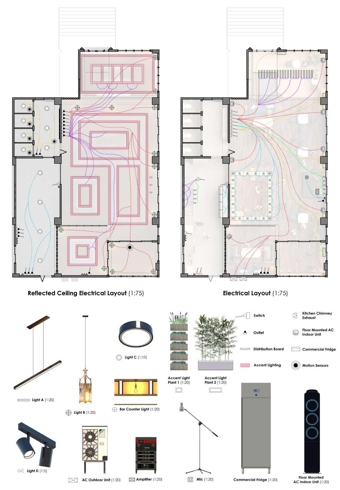
Electrical Layout for Cafe
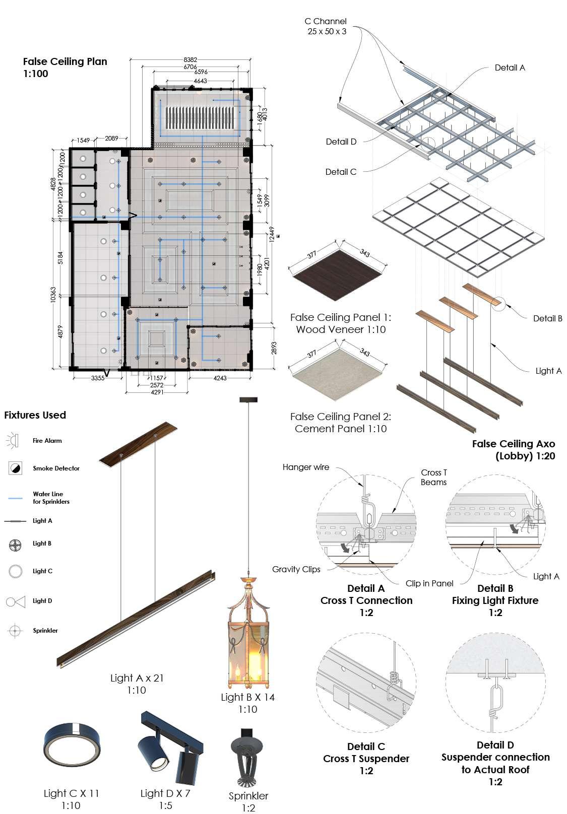
False Celling Drawings for Cafe
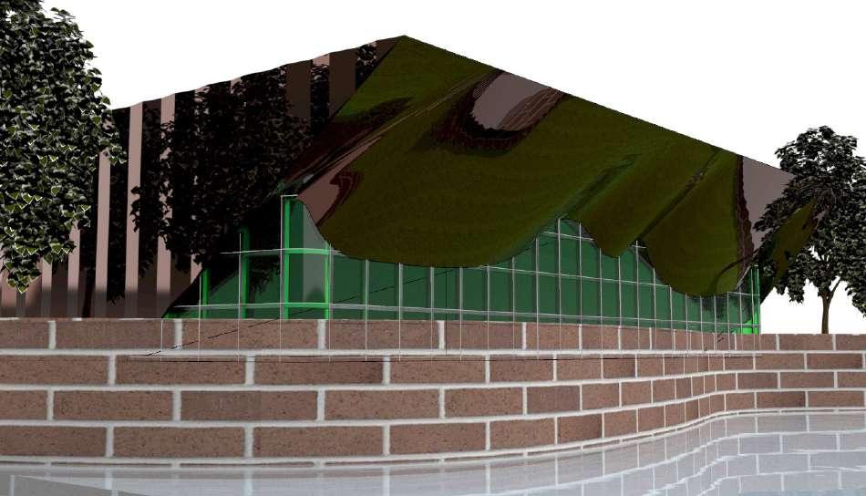
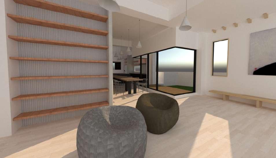
Models & Renders
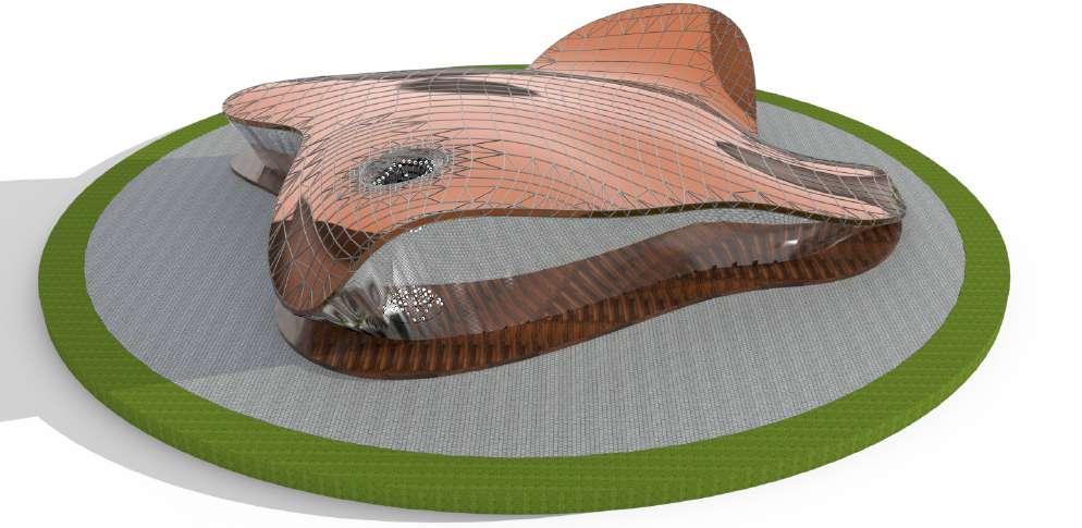
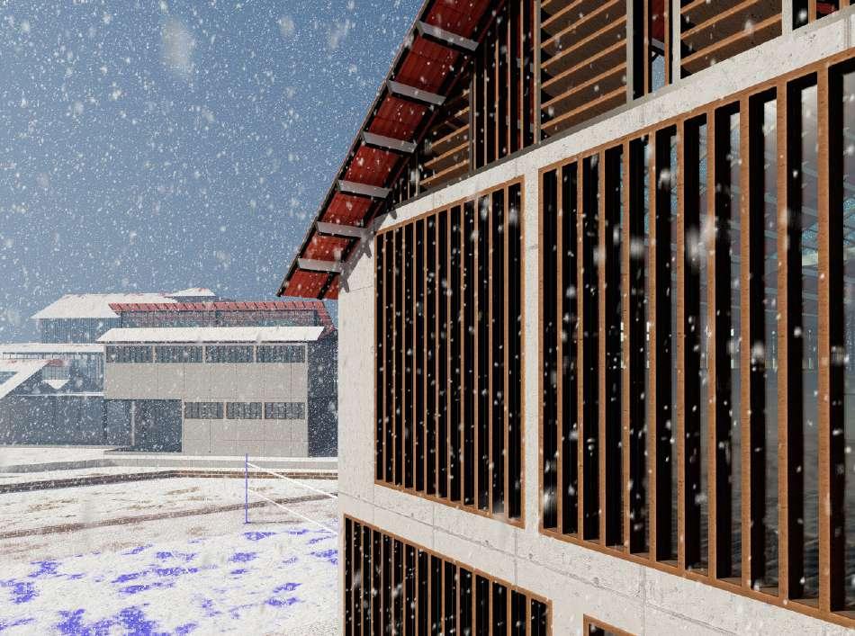
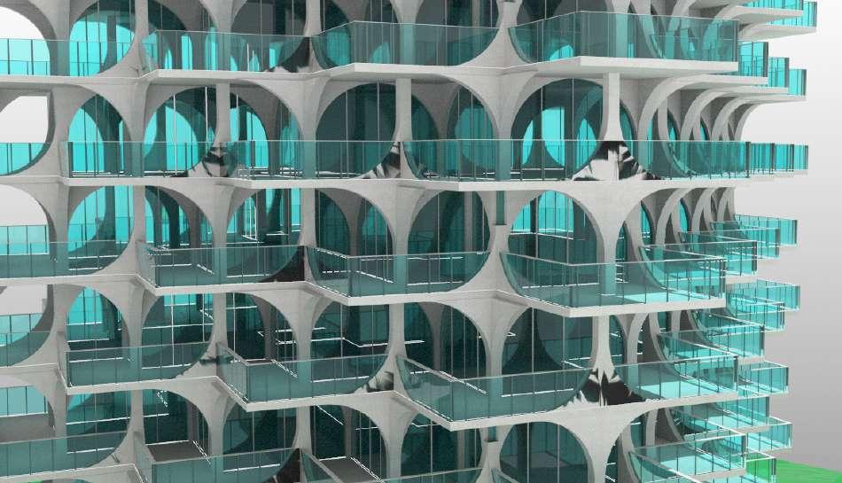
These are some of the 3d models and renders done by me. The 3D models were created on SketchUp and Rhino and the softwares used for the rendering are Photoshop, Illustrator and a few render engines like Vray and Lumion. The postproduction for these images was done Photoshop and Illustrator.

28
Recreation of Terra Project by Orange Architects in Limassol, Cyprus
Recreation of Kilden by ALA architects, in Norway
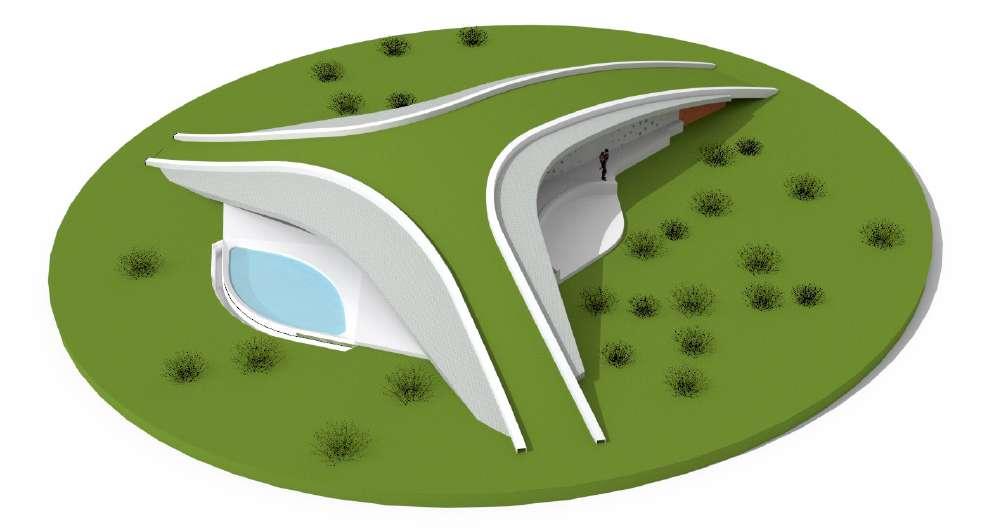
Recreation of Villa Ypsilon by LASSA Architects
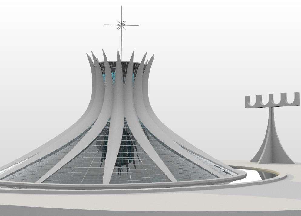
Recreation of Cathedral de Brasilia by Oscar Niemeyer Brazil
3D MODELS
3D MODELS AND RENDERS
29
Alternate Renders for Prathichi School
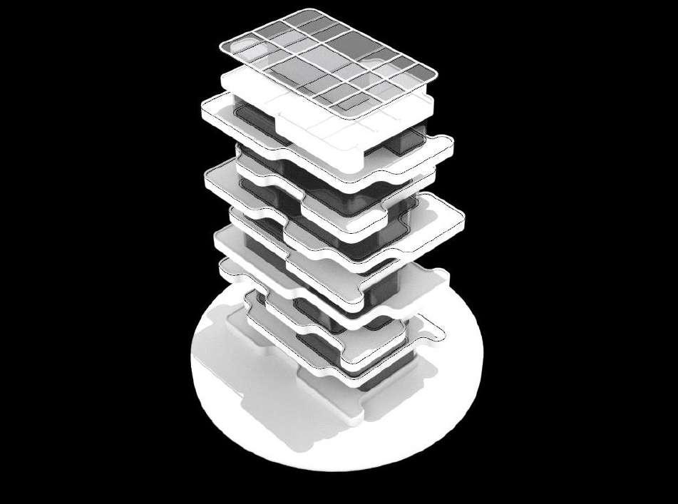
Recreation of Residential Tower by Penda in Tel Aviv
Explorative Design in Rhino
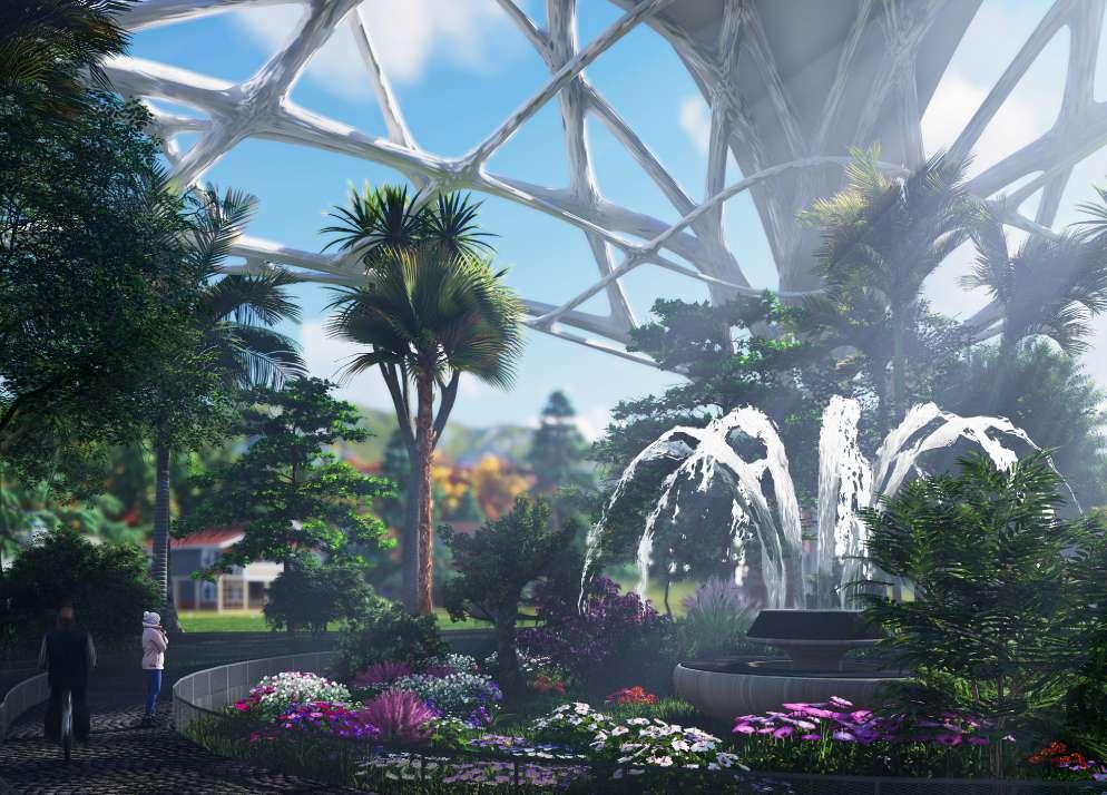
Render from Canopy Design using Biomimicry
PHOTOSHOP AND ILLUSTRATOR RENDERS

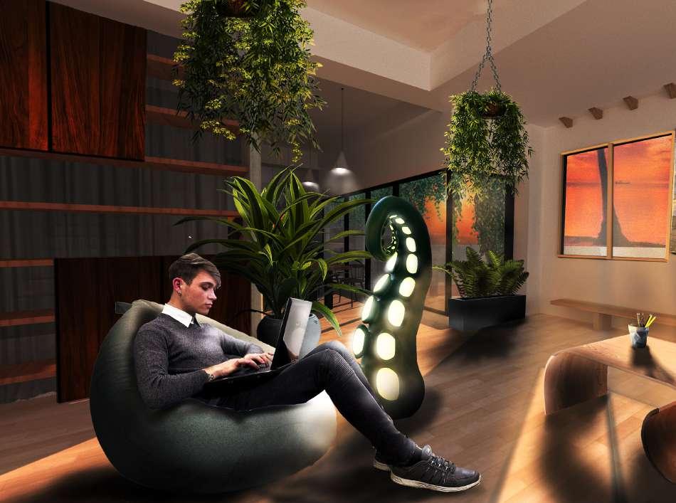
30 C After Before Before After
31
Thank You