SHANE-HUEI, CHU
Architecture Portfolio
Selected Works - 2021-2022
EDUCATION
Shane-Huei Chu
Pomona, CA | (925) - 348 - 3478 | schu@cpp.edu
California State Polytechnic, Pomona Pomona, CA
Bachelor of Architecture, Minor in Urban Planning Jun 2025
WORK EXPERIENCE
Kumagai Gumi
Taipei, Taiwan
Engineer Assistant Jun 2020 - Aug 2020
• Utilized AutoCAD to produce and check construction drawings such as ramp plans, sections, and elevations.
• Inspected and surveyed numerous material options by visiting multiple retailers with the mentor and selecting materials to comply with design requirements.
• Collaborated and communicated with engineers and construction workers onsite ensuring standards of quality and safety control are met, resulting in project completion on time & within budget.
Family Business
Taipei, Taiwan
Drafter Jul 2020 - Jun 2021
• Crafted 35 detailed floor plans using AutoCAD & Rhino for housing safety appraisal reports, surpassing professional standards.
• Accurately measured and drew floor plans of the project, meeting established specifications and deadlines, resulting in the mentor’s ability to calculate the budget accurately.
• Interpreted blueprints & other architectural documents to determine necessary drawings, generating multiple technical drawings within specified timelines.
LEADERSHIP EXPERIENCE
DVC Photography Club Pleasant Hill, CA
Co-Founder Jun 2018 - Jun 2020
• Facilitated weekly team meetings to evaluate topics and themes, optimizing internal communication and goal setting.
• Recruited potential Co-Founders and accelerated the establishment of the club
• Successfully managed multiple housing holding tasks including meeting with the school weekly, managing the social media account, delivering lectures, and providing mentorship for club members.
International Christian Fellowship Pleasnat Hill, CA
Student Leader Jun 2019 - Jun 2020
• Attended weekly meetings with student leaders & faculties to address relevant topics and themes, leading to improved efficiency and productivity.
• Facilitated events on a weekly basis and resolved issues that arose in order to efficiently hold meetings with 50+ students.
• Fostered a welcoming environment while introducing newcomers to the club, ensuring students were not left out.
SKILLS
Skills: AutoCad, Revit, Rhino, Sketchup, Adobe Suite (InDesign, Illustrator, Photoshop), V-Ray, AI text to image tool - (MidJourney, Dall-E-2), Microsoft Office (Excel, Word, PowerPoint)
LANGUAGE
Native: Mandarian
Professional Proficiency: English
CONTENT:
4 - 13
ARC 3021A (SPRING 2023)
MULTI-FAMILY HOUSING
14-17
AI AIDED - FLORAL AIRPORT CONCEPT
ARC 3011 (Fall 2022)
Mt. WILSON SCIENTIST’S RETREAT
ARC 2011 (FALL 2021)
Museum of Japanese Contemporary Art
ARC 2021 (SPRING 2022)
ACADAMIC ARCHITECTURE SCHOOL
Additional Works And Skills
Photography, Hand On, Construction Drawing
18 - 25 26 - 33 40 - 43 40 - 43
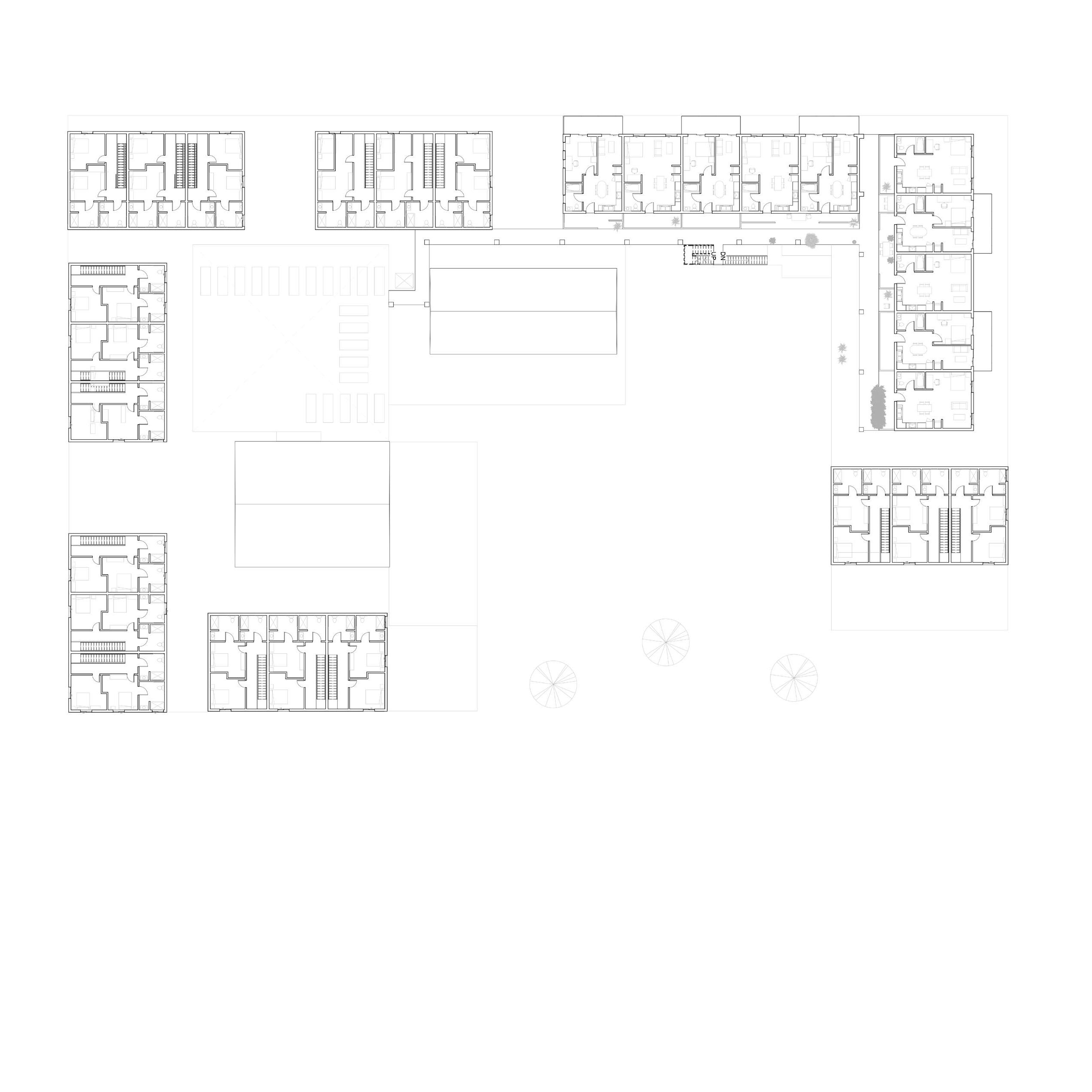
MULTI-FAMILY HOUSING
In this project, the 65 units mixed-use housing next to downtown Santa Ana aims to create a dynamic and inviting courtyard space that serves as a central gathering place for residents and visitors alike every plalce. Each residential unit features a unique front porch and hallway that can be customized to reflect the resident’s personality, fostering a sense of ownership and pride. The building includes amenities such as a daycare center, community room, reading room, game room, and gym to create a comfortable and functional space, which also increase the chance to activate the space. The building’s exterior is made of sustainable and durable materials like stucoo, bamboo panel and glass.
LOBBBY/CIVIC COMMERCIAL 2 BEDROOM LIVE/WORK COMMON AREA AMENITIES STUDIO/1 BEDROOM AXO PROGRAM DIAGRAM
SCALE: 1/32” = 1’-0” SITE SECTION SITE PLAN 0 20 40 80 160 SHANE-HUEI, CHU SCOTT PARKER CPP/ARC SP2023 ARC3021A SITE PLAN AND SITE SECTION (LEFT BY ME AND RIGHT BY MY PARTNER)
GROUND FLOOR, NORTH ELE
COMMERCIAL COMMERCIAL TRASNFORMER ROOM DAYCARE TRASH ROOM LOADING DOCK MAIL ROOM FRONT OFFICE ELECTRICAL MECHANICAL UP UP Level 1 0' - 0" Level 2 10' - 0" Level 3 20' - 0" Level 4 30' - 0" Level 5 40' - 0" Level 6 50' - 0" 1/16" = 1'-0" 1 North
SECOND LEVEL FLOOR PLAN, EAST ELEVATION

DAYCARE GYM ROOF GARDEN UP DN UP
THIRD LEVEL FLOOR PLAN, SECTION AA
UP DN DN READING ROOM READING ROOM COMMON ROOM 1/16" = 1'-0" 2 Section 2
FOURTH LEVEL FLOOR PLAN, SECTION BB
Level 1 0' - 0" Level 2 10' - 0" Level 3 20' - 0" Level 4 30' - 0" Level 5 40' - 0" Level 6 50' - 0" 1/16" = 1'-0" 1 Section 3

PLAZA VIEW


STREET VIEW PROMENADE VIEW

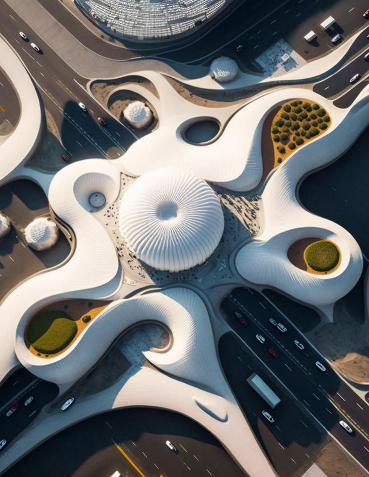
SCHEMATIC DESIGN - FLORAL INTERNATIONAL AIPORT
In this project, I am using artificial intelligence text to image generator - MidJourney as a tool to bring my architectural concept to life. My goal is to design a landmark for a country that offers a truly unique and memorable experience for travelers. To achieve this, I am drawing inspiration from flowers to create a warm and welcoming atmosphere within the terminal. The main terminal building is shaped like a large flower bud, symbolizing the country’s potential for growth and development. The fluid pathway leading to the airside and landside facilities is mimicking the flow of petals, while also guiding travelers to gates. This inspiration is reflected not only on the exterior, but also in the specific details, such as the incorporation of flower-inspired columns within the terminal, which will make it stand out among other airports. This project represents an exciting opportunity for me to push the boundaries of airport design and create a truly beautiful and memorable space for travelers to enjoy.

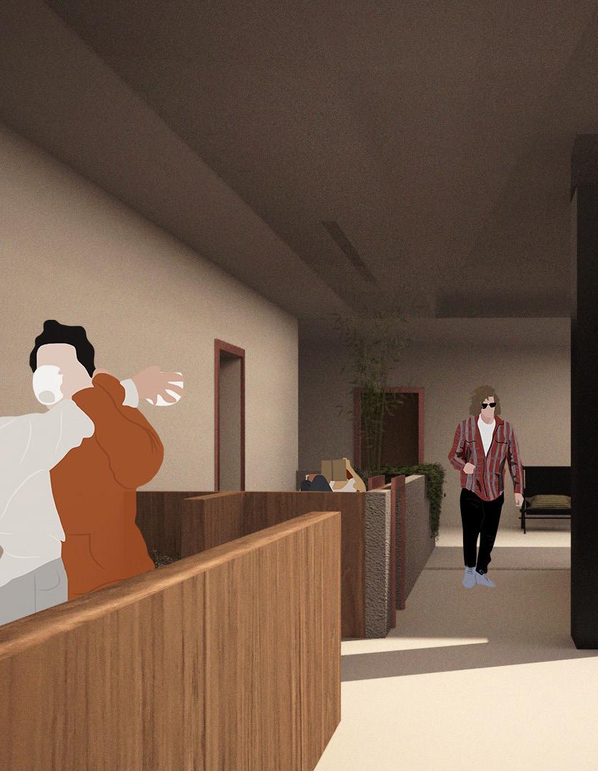
WAITING AREA IN FRONT OF GATES
The flower-inspired columns, not only serve as functional elements of the design but also serve as a striking visual feature throughout the terminal. A gathering and resting space is designed around the column at main lobby, providing travelers with a comfortable and inviting place to wait or meet with friends, colleagues, or family members while traveling. The spaces are designed with comfortable seating, lighting, and charging points to take a break from the trip. The check-in point consists of self-help machines to print boarding pass and baggage tag to check in for their flights.

Supporting by supported by a series of flower-inspired columns, the waiting area at the gate is designed to be a welcoming and comfortable space for travelers. The waiting area is designed with large windows that allow natural light to flood in, creating a bright and inviting atmosphere. The windows also provide views of the surrounding landscape, allowing travelers to enjoy the beauty of the country while they wait for their flight.
 CHECK-IN POINT

DAY ROOM AND KITCHEN (LIVING) LAUNDRY (LIVING) POWDER ROOM (LIVING) RESEARCH OFFICE (RESEARCH) RESEARCH LAB (RESEARCH) OUTDOOR MEETING DECK (PUBLIC) ADA RESTROOM (PUBLIC) ENTRANCE (PUBLIC) PARKING (PUBLIC) CIRCULATION CORE DAY ROOM AND KITCHEN (PRIVATE) BEDROOM (PRIVATE) CIRCULATION CORE CIRCULATION CORE CIRCULATION CORE TRASH (SERVICE) SERVICE CLOSET (SERVICE) PROGRAM DIAGRAM PARTI DIAGRAM AXONOMETRIC PERSPECTIVE CIRCULATION CORE STACK TO CREATE VIEW ACCESS
MOUNTAIN WILSON SCIENTIST’S RETREAT
The project is a combination of private space for astronomers with a public observation deck, located in Mountain Wilson, California. Overlooking Downtown Los Angeles and Pacific Ocean, I decided to approach it vertically, which also meet the brief requirements to limit the touching surface with the site due to sustainable reason. The general form focuses on shifting boxes to break down the scale and also to find a structure grid easily. The public viewing deck is on the first floor and will not affect astronomers’ life while they can access the deck easily since the research office is just one floor upper. Steel moment frames and I-beam trusses serve as structural components, while cement cladding and glass serve as the exterior enclosure.
17'-0" 26'-6" 22'-0" 18'-0" UP A B 1 2 0 5 10 25 GROUND FLOOR PLAN SCALE 1/4" = 1'-0" 3 1 2 1. OUTDOOR DECK 2. PARKING 3. ADA BATHROOM A A B B GROUND PLAN
FLOOR PLANS
1. OUTDOOR DECK 2. PARKING 3. ADA BATHROOM 4. TRASH 5. SERVICE CLOSET 6. RESEARCH OFFICE 7. RESEARCH LAB 8. KITCHEN 9. LIVING ROOM 10. POWER ROOM 11. LAUNDRY 12. OUTDOOR TERRACE 13. BEDROOM 14. BATHROOM 5 4 6 7 8 9 13 11 10 13 12 14 14 BASEMENT PLAN SCALE 1/4" = 1'-0" THIRD FLOOR PLAN SCALE 1/4" = 1'-0" FOURTH FLOOR PLAN SCALE 1/4" = 1'-0" 21'-6" 21'-6" 21'-6" 21'-6" 21'-6" 22'-6" 22'-6" 22'-10 1 2 " 12'-6" 12'-6" 12'-6" 12'-6" 0 5 10 25 UP UP UP A A B B B B B B A A 1 2 A B A B 1 2 A B A B 1 2 1 2
SECTION A SCALE 1/4" = 1'-0" SECTION B SCALE 1/4" = 1'-0" 0 5 10 25 0 5 10 25
LEFT: SECTION AA, RIGHT: SECTION BB
STRUCTURE ANALYSIS
BEAM SPAN: RoT: DEPTH: CANTILEVER SPAN: 18'-4" RoT: C/5 DEPTH: 4' A 5 Item Student: Studio Section: C: ENTIRE SYSTEM - AXON SHANE-HUEI, CHU Yasushi Ishida BEAM SPAN: 22'-6" RoT: L/15 DEPTH: 1'-6" GIRDER SPAN: 15' RoT: L/10 DEPTH: 25'/10=1.5' COLUMN SPAN: 10'-8" RoT: H/25 DEPTH: 10'-8"/25=6" A 5 Item Student: Studio Section: D: ENTIRE SYSTEM AXON SHANE-HUEI, CHU Yasushi Ishida BEAM SPAN: 25' RoT: L/15 DEPTH: 1'-6" CANTILEVER SPAN: 18'-4" RoT: C/5 DEPTH: 4' CANTILEVER SPAN: 22'-5" RoT: C/5 DEPTH: 4.5' A 5 Item Student: Studio Section: A: ENTIRE SYSTEM - AXON SHANE-HUEI, CHU Yasushi Ishida COLOR LEGEND Column Joist Beam Girders/Trusses Lateral x-direction Lateral y-direction Horizontal Bracing Footing Cantilever Porportion A 5 - Item Student: Studio Section: B: ENTIRE SYSTEM EXPLODED AXON SHANE-HUEI, CHU Yasushi Ishida COLOR LEGEND
CODES
1. ROOF COVERING SHALL BE CLASS A AS SPECIFED IN SECTION 1505.2/R902 (705A.21R327.5.2)
2. BUILT-UP ROOFS SHALL HAVE A MINIMUM SLOPE OF 1/4^ PER FOOT (2%) FOR DRAINAGE. (R905.9.11)
3. EXPOSED ROOF DECK ON UNDERSIDE OF UNENCLOSEED ROOF EAVES SHALL CONSIST OF NONCUMBUSTIBLE OR IGNITION RESISTANT MATERIAL. (707A.4:R327.7.4)
4. EXTERIOR WALLS COVERING OR WALL ASSEMBLY SHALL COMPLY WITH NON-CUMBUSTIBLE CONSTRUCTION OR IGNITION RESISTANT MATERIAL. (707A.3;R327.73)
5. PROVIDE A MINIMUM OF 36* STAIR LANDING. (R311.3)
6. PROVIDE INTERIOR AND EXTERIOR STAIRWAY WITH A MINIMUM RISE OF 7.75" AND MINIMUM RUN OF 10* WITH MAXIMUM 3/8* VARIANCE. (R311.7.7.1)
7. PROVIDE INTERIOR AND EXTERIOR STAIRWAY WITH MINIMUM HEADROOM OF 6-8%. (R311.7.2)

8. HANDRAIL HEIGHT SHALL BE 34* TO 38* ABOVE THE NOSING OF TREADS. (R311.7.8.1)
9. GUARDRAIL HEIGHT SHALL BE A MINIMUM OF 42’. (R312.1.1.2)
10. HABITABLE SPACE, HALLWAYS, BATHROOMS. TOILET ROOMS, AND LAUNDRY ROOMS SHALL HAVE A CIELING HEIGHT OF NO LESS THAN 7' (R305.1)
DETAIL CHUNCK AND WALL SECTION
1 2 3 4 5 6 7 10 11 5 8 9 2 4 9
1. CEMENT CLADDING 2. RIGID INSULATION 3. PLYWOOD SHEETING 4. BATT INSULATION 5. INTERIOR FINISH 6. ROOF METAL CLADDING 7. STEEL GRIDER 8. CONCRETE 9. STELL DECKING 10. STEEL CROSS BRACING 11. ANCHOR SYSTEM RAIL AND CLIP KEY SECTION CHUNCK NO SCALE DETAIL SECTION NO SCALE


MUSEUM OF JAPANESE CONTEMPORARY ART
Located in Little Tokyo, the museum was built to exhibit two Japanese artists: Chiharu Shiota and Yoshitomo Nara. The initial concept of the museum project was inspired by the Everson Museum by I. M. Pei with its L shape massing. The main concept of the project is to intersect different volume of L shapes by adding process to create hierarchy spaces and envelope. As program began to be arranged into the museum, I developed a grid system to arrange all the programing into the museum since the L shape is matching with it perfectly. The front of house which include public area and exhibition galleries and the back of house which include support and staff program. The back of house is all located at the ground level and basement level.
SERV I CE ALLEY 0'-0" ST 1 BOOKSTORE 2 CONFERENCE ROOM 3 STAFF RESTROOM 4 STAFF ROOM 5 DIRECTER’S OFFICE 6 OFFICE (6) 7 LOADING DUCK 1 2 3 3 4 5 6 7 FIRST FLOOR PLAN Scale: 1/8” = 1’-0” 1 0 5 10 20 A B C A B B C C UP UP DN UP DN DN GROUND FLOOR PLAN
SERV I CE ALLEY 0'-0" ST 1 EXHIBITION 2 CAFE 3 EXTERIOR SPACE 1 2 3 A A B B C C UP DN UP DN UP DN B C THIRD FLOOR PLAN Scale: 1/8” = 1’-0” 1 0 5 10 20 THIRD FLOOR PLAN
1 0 5 10 20 SECCTION A Scale: 1/8” = 1’-0” SECTION AA
LEFT: SECTION BB, RIGHT: ELEVATION C
 VIEW OF ENTRANCE AT PLAZA LEVEL

INTERIOR VIEW OF MAIN CIRVULATION

ACADAMIC ARCHITECTURE SCHOOL
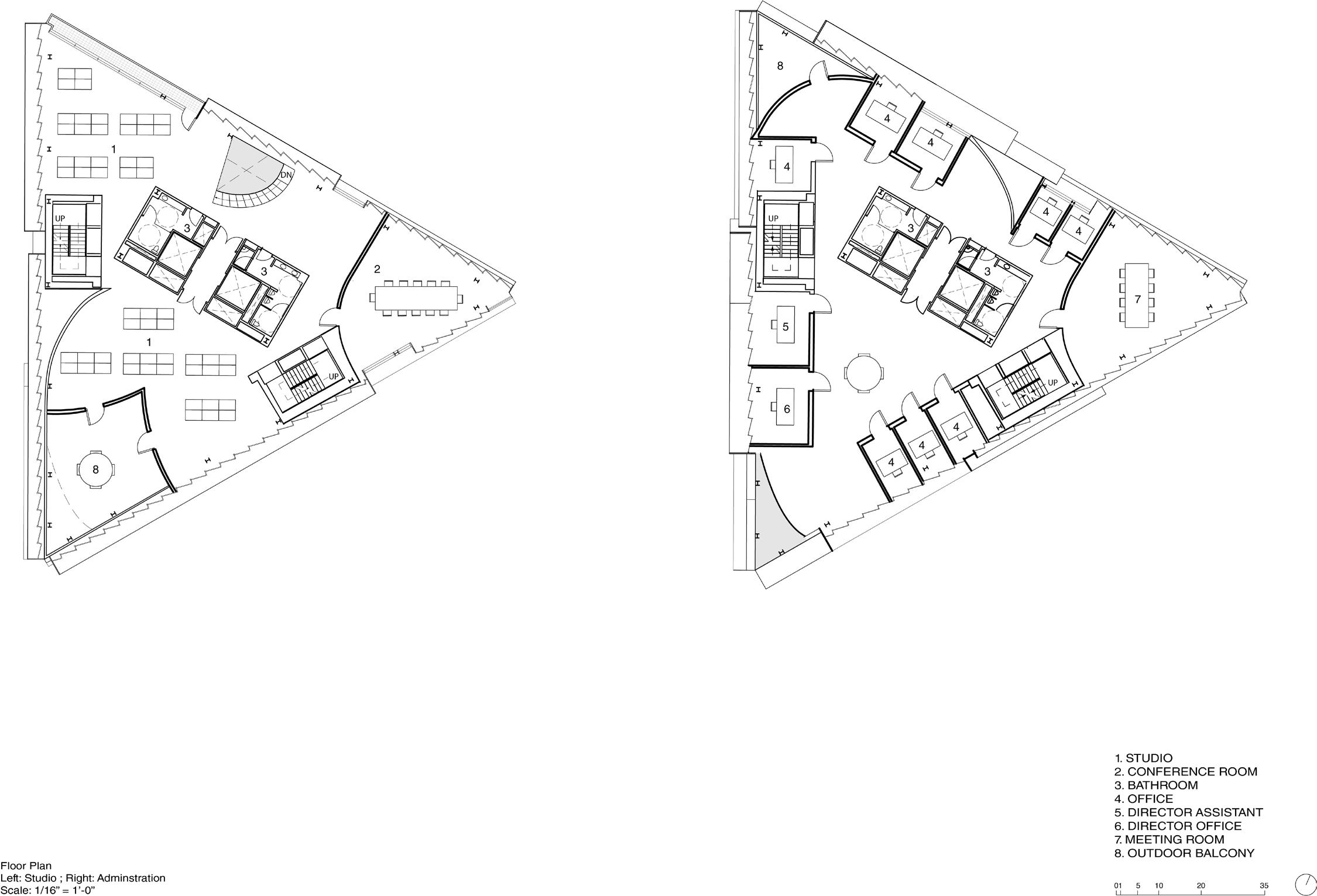
The school of architectures is a project to redesign the decaying iconic Cal Poly Pomona CLA Building. I started with figure ground study and developed a kissing curves concept. The program contains model shop, fab lab, gallery, lecture, and seminar spaces on the plinth and 10 studio spaces and 2 administrations in the tower. The plinth has a domain pathway that connect students from Rose Garden and School of Business Administration. There is another pathway cut through the plinth and the tower to connect Japanese Garden and the back of library. When I think of the school of architecture, I will think of the dynamic atmosphere.To achieve the atmosphere, I decided to make the tower a translucent glass box. I also have secondary stairs to display students’ circulation around studio spaces. To protect the tower from sunlight. I created a façade system that was inspired by KFW Westarkade to have angled glazing. The kissing curves patterns will be frosted windows that are angled to diffuse the light while the flat ground part of the façade will be clear window that was offset 4 feet inward to create an overhang and also serves as an outdoor balcony space.
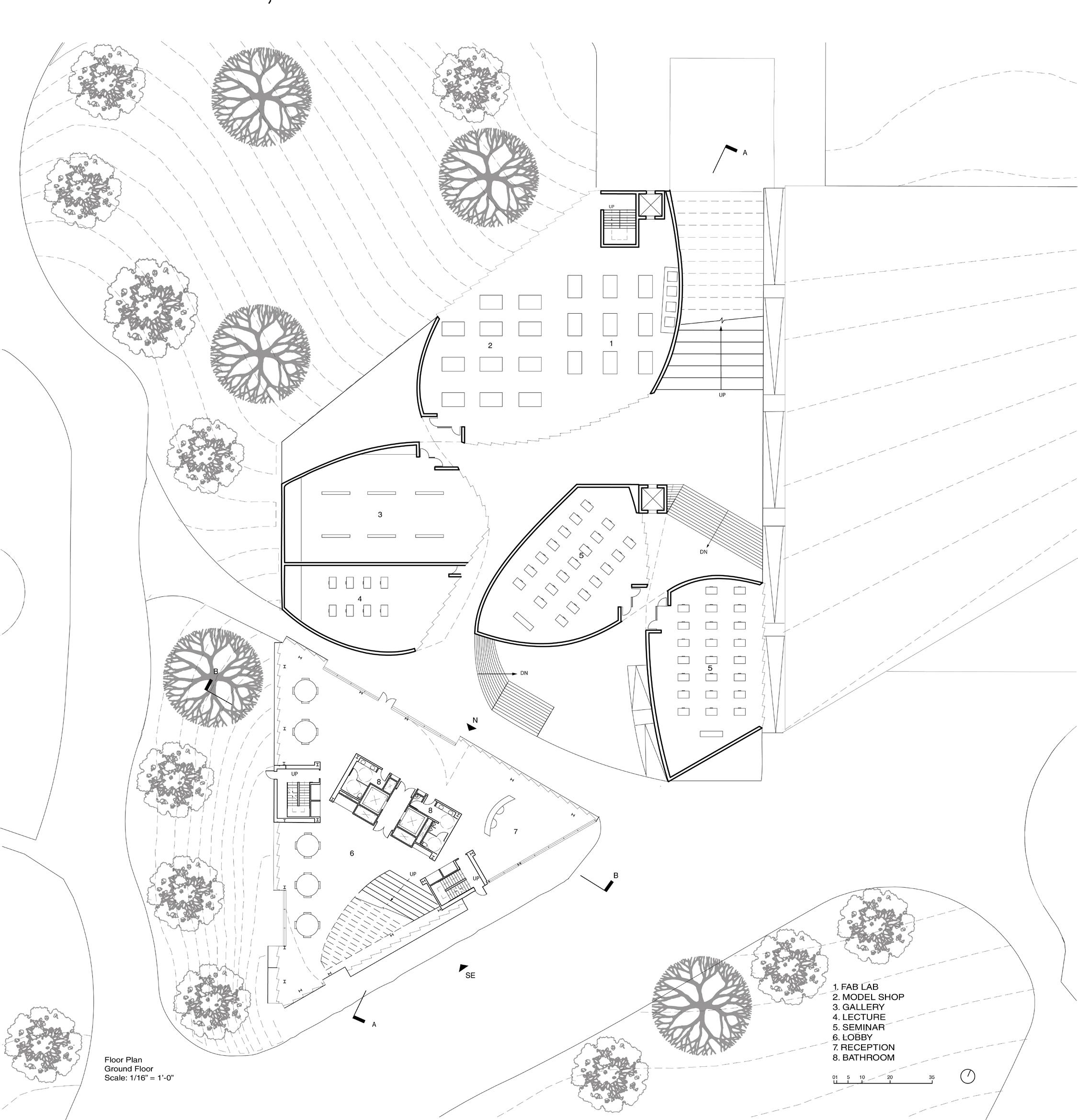
GROUND FLOOR PLAN

Daylight Section
TOP LEFT: STUDIO FLOOR PLAN, TOP RIGHT: ADMIN. FLOOR PLAN
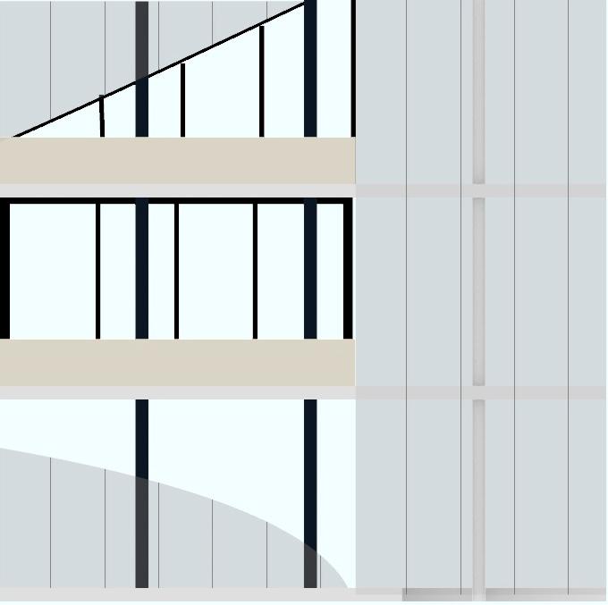
BOT LEFT: FACADE DETAIL, BOT RIGHT: STUDIO VIEW
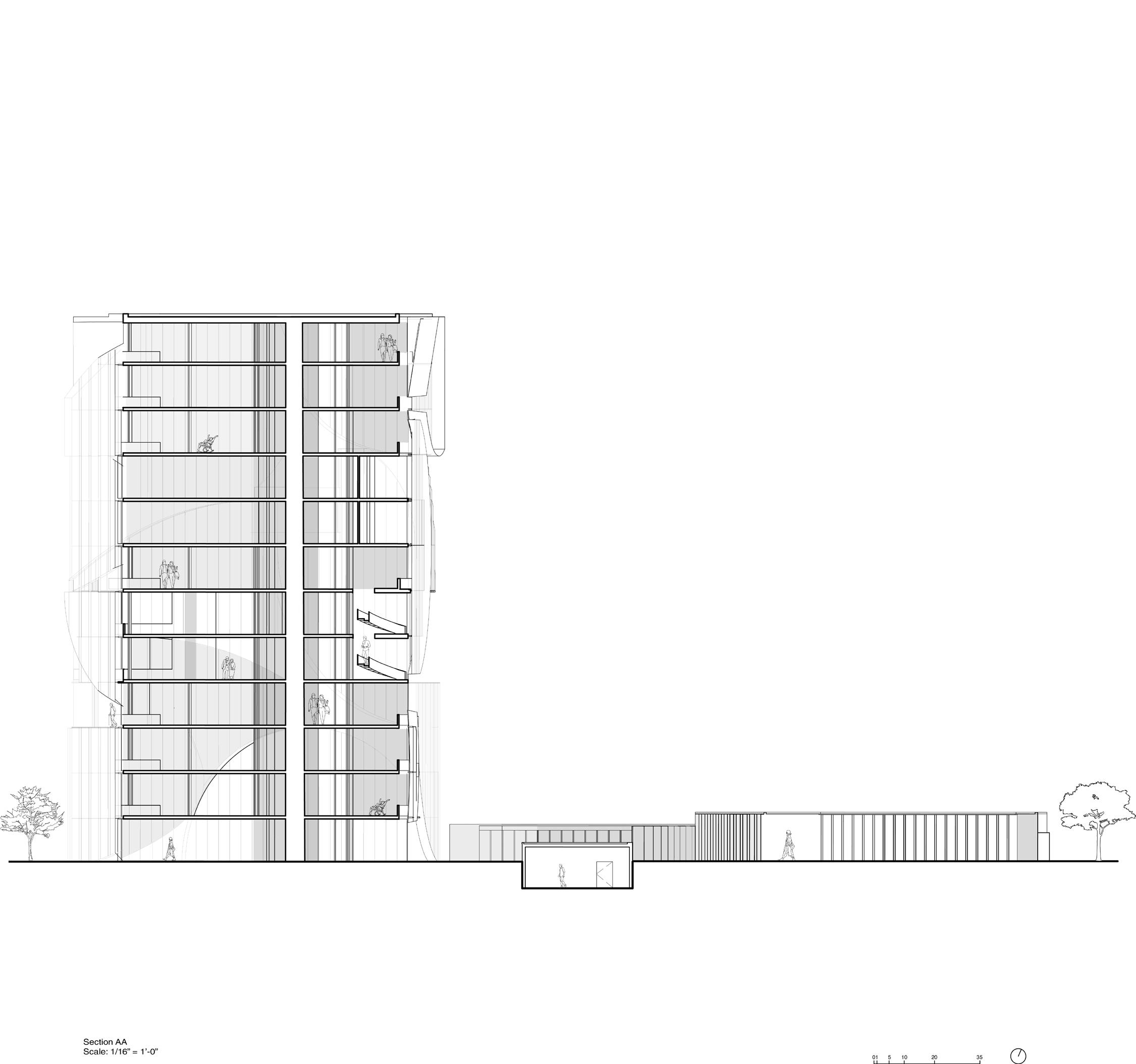
SECTION AA
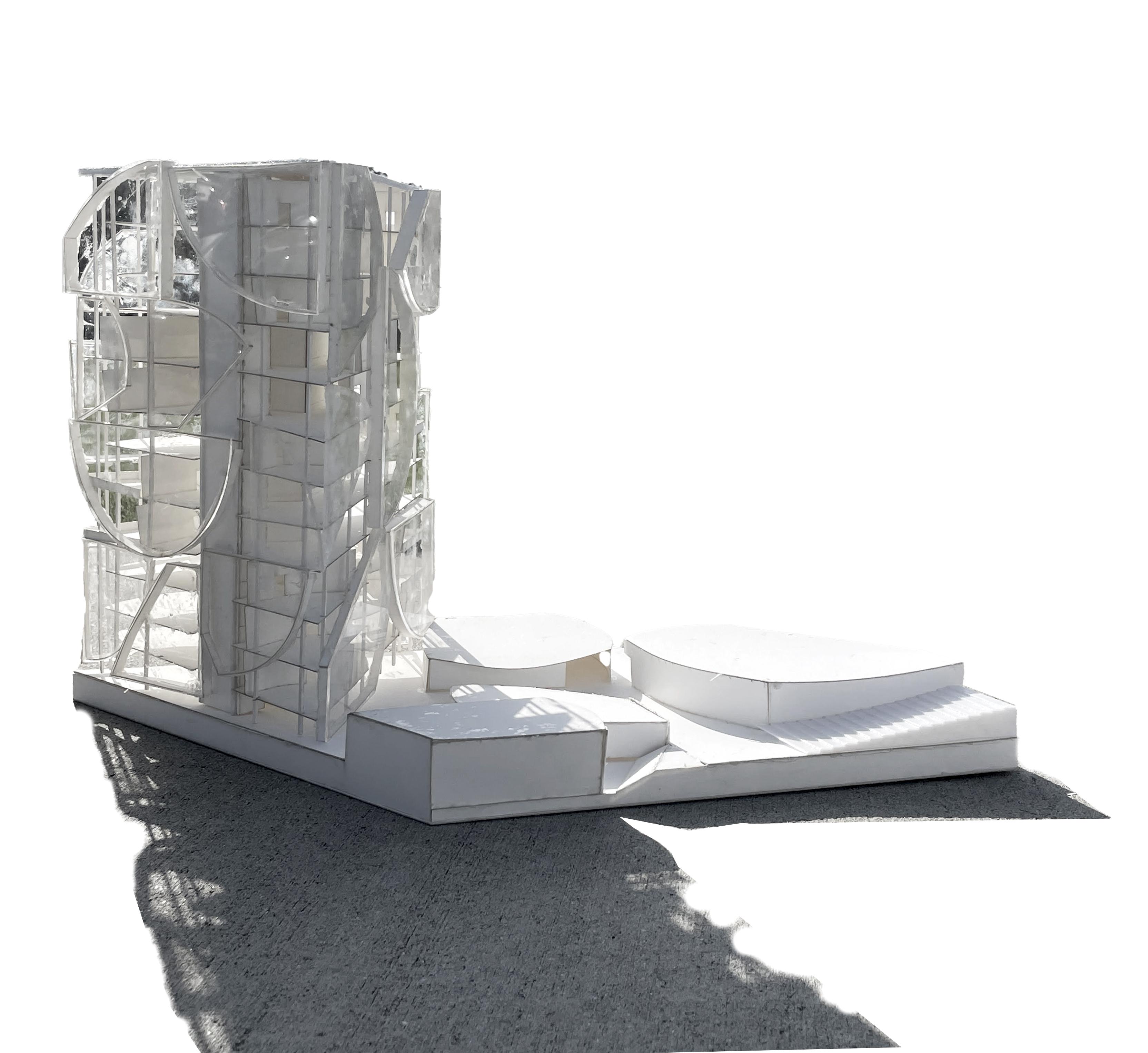
PHYSICAL MODEL
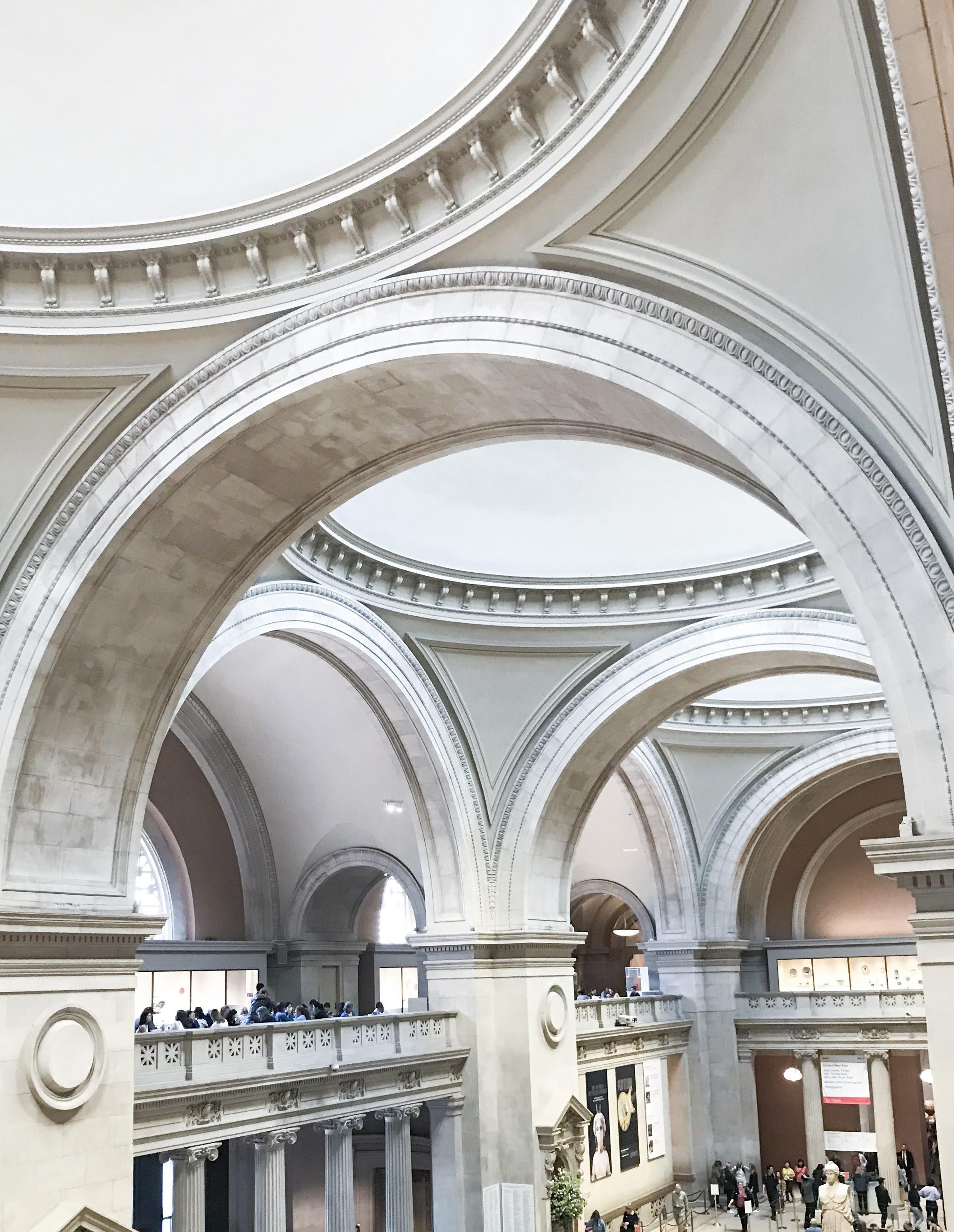
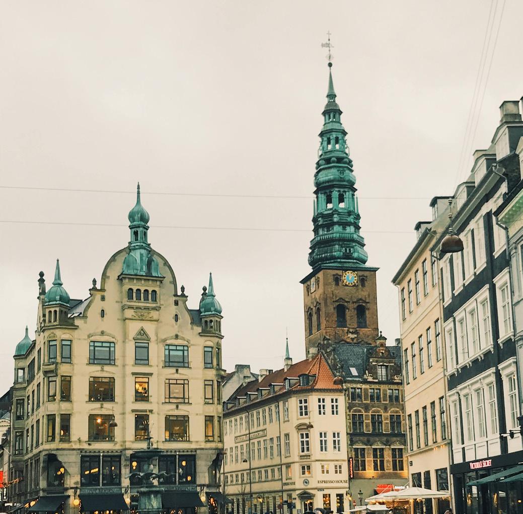
Photography is a hobby that allows me to discover beauty in the everyday and capture it in a way that can be shared and appreciated by others. It is a way for me to see the world in a new perspectives. When traveling, I am particularly drawn to exploring different environments, from grand architectural structures to the small details of daily life. I enjoy observing people in different spaces and how they interact within the space. Photography allows me to document my travels and the unique moments I experience along the way.

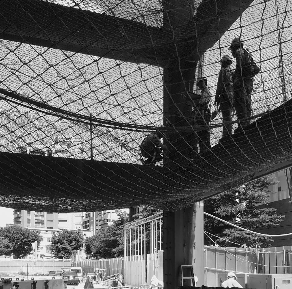
 2020 Summer Intern Documentation
2019 Summer NYC
2019 Europe Trip - Copenhagen
2021 DC Strom
2020 Summer Intern Documentation
2019 Summer NYC
2019 Europe Trip - Copenhagen
2021 DC Strom
HANDS ON
FLOOR PLANS
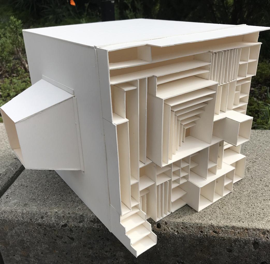
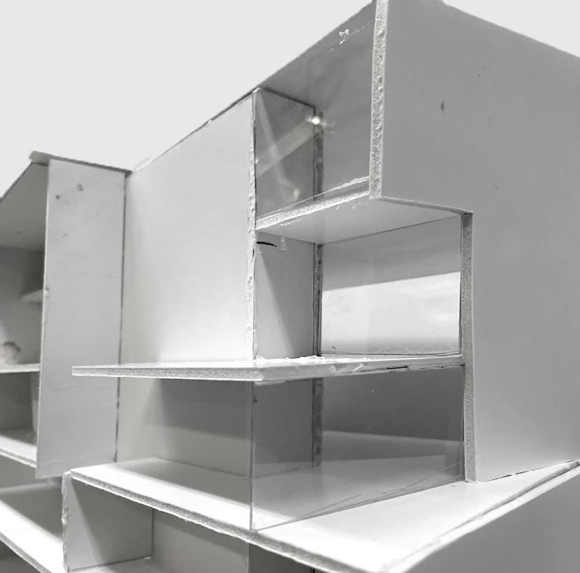 Museum Project - Physical Model
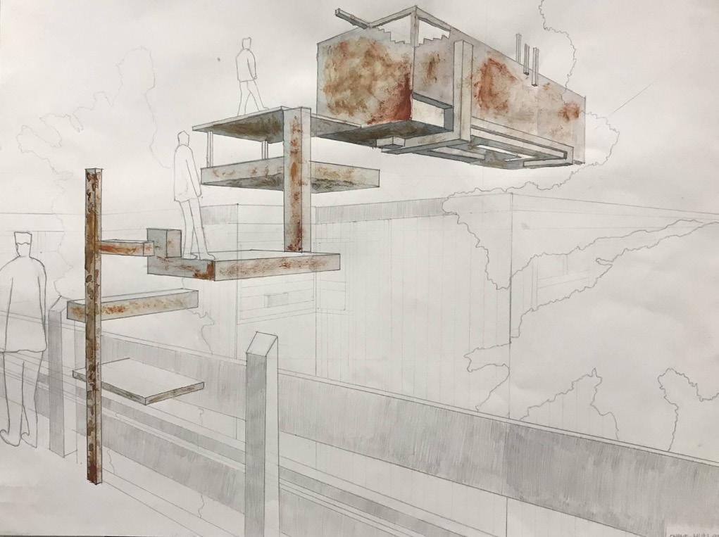
Surreal Space
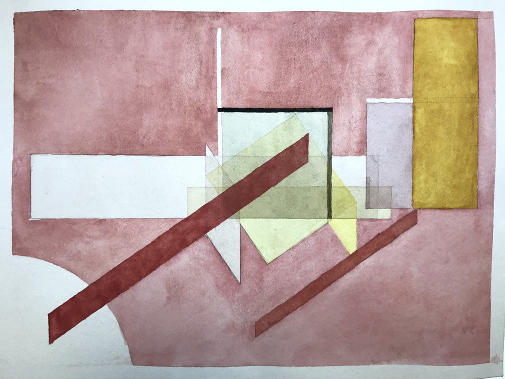
Cube Deconstruction - Hand Render
Museum Project - Physical Model
Surreal Space
Cube Deconstruction - Hand Render
TECHNICAL DRAWING CASE STUDY - ENOUGH HOUSE
FLOOR PLANS
BUILDING SECTIONS
WALL FRAMING ELEVATION
9'-11 9'-9 20'-3" 9'-11 1 9'-10 4 16'-7 2 2'-9 2 16'-7 2 2'-9 2 9'-10 4 13'-10 4 4'-8 19'-9 3 4 29'-3 3 4 29'-3 1 2 2'-0 Enough House UPPER KINGSBURG, CANADA DATE CHECKED BY SHANE-HUEI, CHU REVISIONS NO. DESCRIPTION DATE s.c. L.O. 10.17 A1 FLOOR PLANS A-101 GROUND PLAN 1/4"=1'-0" SECOND FLOOR PLAN 1/4"=1'-0" A-301 2 2 A-301 A-201 1 A-201 1 1 A B C D A B C D 2 15'-1 14'-11 12'-9" Enough House UPPER KINGSBURG, CANADA DATE CHECKED BY SHANE-HUEI, CHU REVISIONS NO. DESCRIPTION DATE s.c. L.O. 10.17 A1 BUILDING SECTIONS 1/4"=1'-0" SECTION 2 1/4"=1'-0" SECTION 1 A-301 A B C D A B C D 1 2 1 2 19'-10 1 10'-1 2'-9 2 9'-11 3 4 9'-10 2'-9 2 16'-7 2 9'-10 3 4 29'-3 2 29'-3 3 19'-9 9'-10 3 4 16'-7 4 Enough House UPPER KINGSBURG, DATE CHECKED BY SHANE-HUEI, REVISIONS NO. DESCRIPTION s.c. L.O. 10.17 A1 REFLECTIVE CEILING PLANS Level 1 1/4"=1'-0" Loft A-111 10'-3 1 2 " 6'-7 1 2 1'-4" 6'-5" 9'-3 1 2 9 10'-2 1 2 " 9'-0 3 4 1'-11 WALL FRAMING PLAN 3/16"=1'-0"
REFLECTIVE CEILING PLAN
THANK YOU SHANE-HUEI, CHU schu@cpp.edu (925) 348-3478
