· No profile / galvanised profile / stainless steel profile
· Pedestrian use and sporadic car traffic with height limitation
· Low hydraulic requirements
· Channel width 100-150-200-300
· No profile / galvanised profile / stainless steel profile
Urban
· Pedestrian use and sporadic car traffic All types of hydraulic requirements
· Channel width 100-150-200-250-300
· No profile / galvanised profile / stainless steel profile
· Option of preslope 0.5%.
48
· Option of cascaded slope Sport
Sports and recreation facilities
· Channel widths: 100-200 Hydro 72
· Plastic channels
· Pedestrian use and sporadic car traffic
· Low hydraulic requirements
· Channel widths: 100-200
· Intermediate loads and road traffic
· Low and medium hydraulic requirements
· Optimised V-shaped section with self-cleaning effect
· Rapidlock® locking system
· 8 locking points per ml
· Channel widths: 100-150-200
· Option of preslope 0.5%.
· Option of cascaded slope
Civil - S
· High loads with height limitation
· Low hydraulic requirements
· Channel width 150-200-250-300
· Locking system Bolted at 8 points per ml
Civil - F
· High loads
· All types of hydraulic requirements
· Channel width 100-150-200-250-300-400
· Locking system Bolted at 8 points per ml
· Monolithic channel
· Specially designed for heavy traffic
· For all hydraulic requirements
· MAXFLOW system, which increases water speed
· Channel width 100-150-200
· Option of different surfaces depending on application
Slotted Gratings
· Hidden drainage grating solution
· Applicable to almost the entire range of channels
· All types of hydraulic requirements
· Channel widths 100-150-200-250-300
· Various slot heights and widths
Who we are
We have been experts in designing, manufacturing and installing highperformance prefabricated polymer concrete since 1990.
We target two market segments: Drainage and Architecture.
With a qualified personable team, technological training, and the know-how acquired over many years of experience, we now offer drainage solutions for a globalized world.
Our certificates
Solutions for Architecture
For our architecture segment, we offer three comprehensive solutions for both new builds and refurbishments.
VENTILATED FACADES ARCHITECTURAL PRECAST
Our group
ULMA Architectural Solutions is part of ULMA Group, , one of the Basque Country’s leading industrial groups, which, in turn, is part of MONDRAGON, the largest cooperative group in the world.
It currently has a significant network of subsidiaries in countries on all five continents. In 2019 we directly employed more than 5200 people, with turnover reaching over 900 million euros.
We have We provide solutions in continents
companies
Present in 80 countries of Turnover
million
Our material
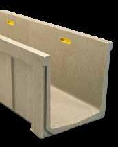
Polymer Concrete is a high quality material composed of a select combination of silica and quartz aggregates.
El Hormigón Polímero
es un material de alta calidad compuesto por una selecta combinación de áridos de sílice y cuarzo.
It is ideal for the evacuation of fluids
The polymeric nature of this material allows smooth surfaces with very low friction on prefabricated elements, thereby facilitating the rapid run-off of fluids and also offering a water absorption index which is virtually non-existent, compared with 5-10% with traditional concrete.
El Hormigón Polímero es un material de alta calidad compuesto por una selecta combinación de áridos de sílice y cuarzo.
Posibilidades de personalización, en textura, forma y dimensión. Por su fabricación mediante moldes ofrece una gran libertad para el diseño. Permite adaptar nuestras piezas prefabricadas a las necesidades de cada proyecto y al criterio del arquitecto. La ligereza de las piezas ofrece un nuevo concepto de estética arquitectónica para las fachadas de los edificios.
Posibilidades de personalización, en textura, forma y dimensión.
Por su fabricación mediante moldes ofrece una gran libertad para el diseño. Permite adaptar nuestras piezas prefabricadas a las necesidades de cada proyecto y al criterio del arquitecto.
La ligereza de las piezas ofrece un nuevo concepto de estética arquitectónica para las fachadas
reaccionan disgregación
soportar hasta 1300 kp/cm frente a los 700 kp/cm que soporta el fibrocemento o los 500 kp/cm2 que soporta el hormigón tradicional. Antes de romperse
the 700 kp/cm2 supported by fi bre cement or 500 kp/cm2 supported by traditional concrete. Before breaking or cracking!
soporta el hormigón tradicional. Antes de romperse o agrietarse!
LA FLEXIÓN
Aplicado soportar que soporta que soporta romperse
A LA ABRASIÓN
La dureza de los agregados de sílice garantiza una buena conservación de las superficies expuestas al
HORMIGÓN POLÍMERO
HORMIGÓN FIBROCEMENTO (CON FIBRA)
HORMIGÓN HIDRÁULICO
HORMIGÓN HIDRÁULICO
CHOQUE
H. Polímero
H. Polímero MPa A LOS Uno de los producto
RESISTANCE TO CHEMICALS
A LOS PRODUCTOS QUÍMICOS
A LOS PRODUCTOS QUÍMICOS
A LOS PRODUCTOS QUÍMICOS
One of the most resistant materials to any chemical product. Its components do not react to contact and prevent disintegration and deformation. Proven!
A LOS PRODUCTOS QUÍMICOS
Uno de los materiales + resistentes a cualquier producto químico. Sus componentes no reaccionan ante el contacto, evitan la disgregación y la deformación. Demostrado!
Uno de los materiales + resistentes a cualquier producto químico. Sus componentes no reaccionan ante el contacto, evitan la disgregación y la deformación. Demostrado!
Uno de los materiales + resistentes a cualquier producto químico. Sus componentes no reaccionan ante el contacto, evitan la disgregación y la deformación. Demostrado!
Uno de los materiales + resistentes a cualquier producto químico. Sus componentes no reaccionan ante el contacto, evitan la disgregación y la deformación. Demostrado!
Sin efectos visibles Daños apreciables
No visible effects Considerable damages
Sin efectos visibles Daños apreciables
A LA FLEXIÓN
A LA FLEXIÓN
FLEXURAL STRENGTH
A LA FLEXIÓN
Aplicado a los sistemas prefabricados, llega a soportar hasta 18-25 MPa frente a los 15-20 que soporta el fribrocemento o los 1-5 MPa2 que soporta el hormigón tradicional. Antes de romperse o agrietarse!
A LA FLEXIÓN
Aplicado a los sistemas prefabricados, llega a soportar hasta 18-25 MPa frente a los 15-20 que soporta el fribrocemento o los 1-5 MPa2 que soporta el hormigón tradicional. Antes de romperse o agrietarse!
Applied to prefabricated systems, it can support up to 18-25 MPa compared to the 15-20 supported by fi bre cement or the 1-5 MPa2 supported by traditional concrete. Before breaking or cracking!
Aplicado a los sistemas prefabricados, llega a soportar hasta 18-25 MPa frente a los 15-20 que soporta el fribrocemento o los 1-5 MPa2 que soporta el hormigón tradicional. Antes de romperse o agrietarse!
Aplicado a los sistemas prefabricados, llega a soportar hasta 18-25 MPa frente a los 15-20 que soporta el fribrocemento o los 1-5 MPa2 que soporta el hormigón tradicional. Antes de romperse o agrietarse!
Al ser un material compuesto, garantiza la perfecta conservación de las superficies frente al uso o paso del tiempo. Sin percepción de desgaste!
Al ser un material compuesto, garantiza la perfecta conservación de las superficies frente al uso o paso del tiempo. Sin percepción de desgaste!
SHOCK RESISTANCE
AL CHOQUE
Al ser un material compuesto, garantiza la perfecta conservación de las superficies frente al uso o paso del tiempo. Sin percepción de desgaste!
As it is a composite material, it guarantees the perfect conservation of surfaces against usage or the passing of time. No perception of wear!
Al ser un material compuesto, garantiza la perfecta conservación de las superficies frente al uso o paso del tiempo. Sin percepción de desgaste!
Cuenta con un % prácticamente nulo de absorción de agua y garantiza la estanqueidad de las piezas. Impermeabilidad! 0-0,3% 5-10% NULA ABSORCIÓN AGUA
NULA ABSORCIÓN AGUA
ZERO WATER ABSORPTION
NULA ABSORCIÓN AGUA
Cuenta con un % prácticamente nulo de absorción de agua y garantiza la estanqueidad de las piezas. Impermeabilidad! 0-0,3% 5-10%
It has practically 0% water absorption and guarantees the sealing of the pieces. Impermeable!
Cuenta con un % prácticamente nulo de absorción de agua y garantiza la estanqueidad de las piezas. Impermeabilidad! 0-0,3% 5-10%
Cuenta con un % prácticamente nulo de absorción de agua y garantiza la estanqueidad de las piezas. Impermeabilidad!
0-0,3% 5-10%
INALTERABLE A LOS CICLOS DE HIELO/DESHIELO
INALTERABLE A LOS CICLOS DE HIELO/DESHIELO
INALTERABLE A LOS CICLOS DE HIELO/DESHIELO
UNALTERABLE IN FREEZE/ THAW CYCLES
Al contrario que los materiales tradicionales no se ve afectado por los ciclos de hielo-deshielo y evita la aparición de fisuras o grietas. Mantiene intactas todas las propiedades!
Al contrario que los materiales tradicionales no se ve afectado por los ciclos de hielo-deshielo y evita la aparición de fisuras o grietas. Mantiene intactas todas las propiedades!
Al contrario que los materiales tradicionales no se ve afectado por los ciclos de hielo-deshielo y evita la aparición de fisuras o grietas. Mantiene intactas todas las propiedades!
On the contrary to traditional materials it is not aff ected by freeze-thaw cycles and prevents the appearance of fissures or cracks. It maintains all properties intact!
INALTERABLE A LOS CICLOS DE HIELO/DESHIELO
Al contrario que los materiales tradicionales no se ve afectado por los ciclos de hielo-deshielo y evita la aparición de fisuras o grietas. Mantiene intactas todas las propiedades!
LIGEREZA Inalterado Filtra el agua y fisura el material
LIGEREZA Inalterado Filtra el agua y fisura el material
LIGEREZA Inalterado Filtra el agua y fisura el material
Unchanged Filtered and frozen, Crack in the material
Inalterado Filtra el agua y fisura el material
Gracias a sus excelentes propiedades mecánicas, permite la realización de piezas con perfil más fino y de menores dimensiones.
LIGHTWEIGHT
Gracias a sus excelentes propiedades mecánicas, permite la realización de piezas con perfil más fino y de menores dimensiones.
Gracias a sus excelentes propiedades mecánicas, permite la realización de piezas con perfil más fino y de menores dimensiones.
Thanks to its excellent mechanical properties, it allows pieces with a fi ner profi le and smaller dimensions to be made.
LIGEREZA
Gracias a sus excelentes propiedades mecánicas, permite la realización de piezas con perfil más fino y de menores dimensiones.
H.Hidráulico
H. Polímero
Fibrocemento (con fibra)
H. Polímero
We offer the best drainage system
We are committed to sustainable water management.
The importance of a good drainage system lies not only in the need for rapid discharge of surface water, but also in doing so in a rational manner, with lower peak flows and adequate quality.
Today, when rationalisation of resources is becoming increasingly important in society and in environmental policies, ULMA is committed to working alongside developers and designers to ensure sustainable urban drainage systems in town planning.
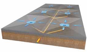
WHY LINEAR DRAINAGE
Our duct and drainage system is based on LINEAR DRAINAGE, which offers many advantages over point drainage.
• Easier installation of paving.
• No need for underground water.
• More profitable in terms of final cost of the drainage network.
• Prevents waterlogging in specific areas.
• Increased hydraulically efficiency than that of point drainage.
• The grating allows access at any point, making it easy to clean and maintain the network.
• Absorbs minimal ground slopes without the need for complicated construction work.
What sets us apart
THE BENEFITS OF POLYMER CONCRETE IN DRAINAGE CHANNELS
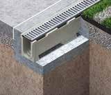
Polymer concrete manufactured by ULMA is an excellent material for surface drainage channels.
Apart from its outstanding properties in terms of strength, the resins that make up polymer concrete provide an extremely smooth surface compared to traditional concrete. This gives the channels up to 30% more hydraulic capacity, bringing a reduction in hydraulic section. This fact, combined with narrower sections thanks to the material’s strength characteristics, ensures more optimised channels.
In addition to the proven quality of the material, this reduction in the size of the channels brings a series of benefits in terms of installation, particularly with regard to cost and time savings.
• Room for other parallel facilities, kerbs...
• Less digging.
• Narrower gratings.
• Aesthetics.
%Q
• Less volume of concrete needed.
Our complete drainage system
We offer complete drainage system with all the required products, from water collection up to the point of discharge, with a range of channels that adapt to the requirements of each project, manufactured in accordance with Standard UNE EN-1433.
CHANNELS
SUMP UNITS GRATINGS
LOCKING SYSTEM
BUCKET LATERAL OUTLETS END CAPS
SLOPE CONFIGURATIONS
WITHOUT SLOPE
All of the channels are placed at the same height.
Advantages: Very simple from an execution point of view. It has a hydraulic capacity sufficient for short stretches of drainage.
Channels of variable height with a built-in slope of 0.5% and 2.5%, according to the model.
Advantages: Very appropriate for areas where the ground has no natural slope.
CASCADE SLOPE
A combination of straight channels of various heights that are joined using step connectors.
Advantages: Simple and economic onsite execution when slopes need to be included.
MIXED SLOPE
A combination of the previous systems.
Advantages: Very appropriate to drain longlength stretches. It allows for the optimization of hydraulic capacity to the utmost.
Gratings
We are focused on customers’ needs
We offer a complete range of gratings in various materials and designs.
In addition to gratings for pedestrian and vehicle use, we have a wide range of gratings for heavy-duty areas such as ports, docks and airports. All our gratings are designed according to the European Standard EN-1433 which regulates covering and sealing devices for use in pedestrian and vehicle circulation areas, classifying the gratings in six categories, in accordance with the place of installation.
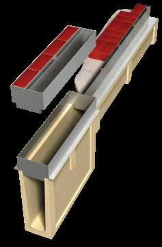
GALVANISED & STAINLESS
LOCKING SYSTEMS
CLICK LOCKING SYSTEM WITHOUT SCREW
• Especially for channels with no galvanized edge,nor cast iron edges.
• Specific for A15 load classes.
• No screws.
LOCKING BAR AND SCREW
• Channels with and without edge-on.
• Up to load class C250.
• Two locking bars and two screws per LM
SCREW TO THE CHANNEL BASE
• Channels with or without edges.
• Up to load class C250.
• Two screws per LM.
BOLTLESS LOCKING SYSTEM
• Channels with profile
• Up to load class D400
• 8 fixing points per LM
8 BOLTS PER GRATING
• Channels with galvanized or cast iron edges.
• Load classes from D400 up to F900.
• 8 screws per LM.
Single slot Double slot Side slot
Slotted Mesh Length Slotted
Solution adapted to your project
1.
LOAD CLASSES
Suitable channels must be chosen for each type of application, based on load class, in order to ensure they meet the strength capacity requirement. At ULMA we have channels for all types of applications.
STANDARD EN 1433
The products set out in this Technical Dossier are designed under the premises of Standard EN 1433 “Drainage channels for vehicular and pedestrian areas. Classification, design and testing requirements, marking and evaluation of conformity”.
2. HYDRAULICS
ULMA Architectural Solutions
Hydraulic Calculation software
SIMPLICITY
It only requires a few project parameters, such as line lengths, catchment areas, slopes and run-off coefficients of each surface, to accurately reflect the current situation and the subsequent study.
PRECISION
To calculate the water’s behaviour in the channels a mathematical model is used that takes the Spatially Varied Flow with Increasing Flow for Open Channels as the base, which describes the water’s behaviour more accurately than other commonly used models and formulas.
COST REDUCTION
The software optimises the cost of channel lines by selecting the most appropriate channel for the application, the exact location of intermediate outlets or the exact distribution of channels in cascade slope.
3. APPLICATION
To ensure drainage systems with optimal evacuation capacity and cost, ULMA Architectural Solutions has developed a multi-platform software solution offering the possibility of performing a hydraulic study for each project and precisely defining the most suitable channel.
MULTIPLE FUNCTIONALITIES
You can enter different rainfall data for any geographic area worldwide, calculate different channel lines in the same project and find the right channel among hundreds of references in ULMA’s extensive catalogue, based on their Heights, Widths, Sections, Load Classes or other characteristics.
DETAILED REPORT
As a result we obtain a report with references and dimensions of the necessary channels, sheet of water, filling percentages, water flows and speeds in each of the project lines. All the necessary data for the validation of the drainage system.
Qref
The value shown as Qref in the product datasheets refers to the maximum flow rate for a length of 10 metres and 0% slope.
Each area of application has its own requirements, and at ULMA we have a wide variety of products and materials to respond to each of them. Checking with the technical department is recommended in order to ensure a correct choice.
ENVIRONMENTAL REQUIREMENTS
Using channels with stainless steel profiles or ductile iron edges, along with gratings in the same material, is recommended for environments with high salinity, as well as places where chemicals are used.
USE REQUIREMENTS
We have a wide range of gratings to meet the requirements of different Standards.
Improve safety
With its many years of experience in the area of surface drainage, ULMA’s technical department is at your disposal to accompany you throughout the entire project.
SETTING-OUT THE DRAINAGE LINES
Send us your plans and we will help you design the best way to drain the surface of your project. We will also advise you on choosing the right kind of resistance for the channels and gratings depending on their use and location.
CHOOSING THE MOST OPTIMAL CHANNEL AND GRATING
With our Optimal Drain hydraulic calculation, we will find the optimal channel with the lowest possible cost.
COMPLETE DRAINAGE SYSTEM
We will advise you to ensure your drainage project is as complete as possible. We will develop the exploded view of the entire system to ensure no element or accessory is missing. Sump units, connectors, covers...
DOCUMENTATION FOR THE PROJECT
We will provide you with all the necessary documentation for the project. Data sheets, plans, files, BIM, DOP, quality control certificates...
ADVICE ON INSTALLATION ON SITE
After we send you the material, we will still be there. We will advise you on installing the channels, defining the necessary concrete reinforcement, in addition to being present on site if required.
Domestic drainage
Self
Channels for pedestrian use and occasional car traffic, for areas with low hydraulic requirements. Using a channel with a built-in profile is recommended, especially when finished with concrete or asphalt paving and/or with frequent passage of vehicles.
Mini
Channels designed for areas with height limitation, pedestrian use and occasional traffic. Using a channel with a built-in profile is recommended, especially when finished with concrete or asphalt paving and/or with frequent passage of vehicles.
Urban
Channels for pedestrian use and occasional car traffic, for all types of hydraulic requirements. Using a channel with a built-in profile is recommended, especially when finished with concrete or asphalt paving and/or with frequent passage of vehicles. Option of built-in slope, mixed slope or cascaded slope.
Sport
Drainage channels for sports and recreation facilities.
Applications
Secondary streets, squares, playgrounds, schools, parks, gardens, etc.
Pedestrian areas, sports facilities, residential complexes, car parks for light vehicles, etc.
Load class up to C250 (according to model).
Load class up to C250 (according to model).
Applications
Football pitches, running tracks, showers, changing rooms, swimming pool paving, etc.
Hydro
Polypropylene drainage channels for pedestrian use and occasional car traffic, for areas with low hydraulic requirements.
Applications
Secondary streets, squares, playgrounds, schools, parks, gardens, etc.
Load class up to C250 (according to model).
Load class up to C250 (according to model).
> Domestic drainage > Technical drainage
Civil drainage
Technical drainage
Civil drainage
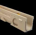
MultiV+
Channels with versatile uses suitable for intermediate loads and road traffic for areas with low and medium hydraulic requirements. Optimised V-shaped section with self-cleaning effect.
• Rapidlock® locking system
• Mechanical stability in 8 locking points
• Option of built-in slope, mixed slope or cascaded slope.
Civil - S
Channels for large loads in areas with height limitations. Locking system with 8 bolts per linear metre.
Civil - F
Drainage channels for large loads and all types of hydraulic requirements. Option of built-in slope, mixed slope or cascaded slope. Locking system with 8 bolts per linear metre.
Applications
Pedestrian areas, commercial areas, and car parks for all types of vehicles.
Applications
Reinforced slabs, garage flooring structure, service stations, loading and unloading areas, industrial buildings, public roads, heavy vehicle car parks, etc.
Applications
Service stations, port loading and unloading areas, industrial buildings, airports, public roads, heavy vehicle car parks, etc.
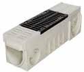
KompaqDrain®
Monolithic channel with built-in grating in a single body, for medium or high loads, specially designed for intense vehicle traffic. Useful for all types of hydraulic requirements.
Incorporates innovative MAXFLOW system, which increases water speed.
Hidden drainage grating solution, applicable to almost the entire range of channels, for all hydraulic requirements. In galvanised or stainless steel.
Load classes up to D-400
Load class up to D400
Applications
Motorways or dual carriageways, airports, service stations, and areas with heavy traffic.
Multipurpose, constant height channels (without slope), very practical in short drain stretches or with frequent outlets.
Available with various grating locking systems (quick system, locking bars, with screws), all types of grating materials up to load class C250.
Load Class up to A15 EN-1433 Standard
EUROKIT
ULMA Linear Drainage Channel type EUROKIT: External width 120 mm; Internal width 98 mm and overall height 85 mm to collect rainwater in 1 metre long units. Locking system “click” type without screws.
Load Class up to C250 EN-1433 Standard
EUROSELF
ULMA Linear Drainage Channel type
EUROSELF: External width 127 mm; Internal width 100 mm and overall height 95 mm to collect rainwater in 1 metre long units. Locking system consist of locking bar and screws.
Load Class up to C250 EN-1433
EUROSELF V+
ULMA Linear Drainage Channel, type EUROSELFV+; External width 130 mm,Internal width 100 mm; Available with overall heights between 95 mm and 145 mm, to collect rainwater in 1 meter long units, optimized V-shape with selfcleaning effect; especially designed for channel runs with no longitudinal slope. Locking system consist of locking
CHANNELS GRATINGS
DOMO
ULMA Linear Drainage Channel type DOMO: External width 130 mm; Internal width 100 mm and overall height 80 mm to collect rainwater in 1 metre long units. The locking system consists of 2 screws per metre.
CHANNEL
GRATINGS
SUMP UNITS
Load Class up to C250 EN-1433 Standard
ULMA Linear Drainage Channel type SELF: External width 130 mm; Internal width 100 mm and overall height 115 mm to collect rainwater in 1 metre long units. Locking system consists of locking bar CS100 and screws.
CHANNEL
GRATINGS
SUMP UNITS
Load Class up to C250
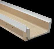
ULMA Linear Drainage Channel type SELFK: External width 130 mm; Internal width 100 mm and overall height 100 mm to collect rainwater in 1 metre long units. Integrated galvanised steel* edges for lateral protection. Locking system consists of 2 screws per metre.
*Also available with stainless steel edge protection
CHANNEL
GRATINGS
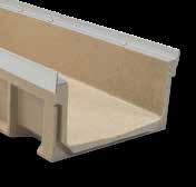
EUROSELF200
ULMA Linear Drainage Channel type EUROSELF200: External width 200 mm; Internal width 150 mm and overall height 70 mm to collect rainwater in 1 metre long units. Locking system consists of 2 screws per metre.
CHANNEL
Vertical outlets on order STE
Class up to C250 EN-1433 Standard
SELF200K
ULMA Linear Drainage Channel type SELF200K: External width 204 mm; Internal width 150 mm and overall height 162 mm to collect rainwater in 1 metre long units. Integrated galvanised steel* edges for lateral protection. Locking system consists of locking bar CS150 and screws.
*Also available with stainless steel edge protection.
Vertical outlets on order STE
Heelproof Mesh
* Available in stainless steel, consult design
SELF250
ULMA Linear Drainage Channel type SELF250: External width 260 mm; Internal width 200 mm and overall height 155 mm to collect rainwater in 1 metre long units. Locking system consists of locking bar CS200 and screws.
CHANNEL GRATINGS
Load Class up to C250 EN-1433 Standard
SELF250K
ULMA Linear Drainage Channel type SELF250K: External width 260 mm; Internal width 200 mm and overall height 180 mm to collect rainwater in 1 metre long units. Integrated galvanised steel edges for lateral protection. Locking system consists of locking bar CS200 and screws.
IRON
* Available in stainless steel, consult design
SELF300
ULMA Linear Drainage Channel type SELF300: External width 300 mm; Internal width 250 mm and overall height 190 mm to collect rainwater in 1 metre long units. Locking system consists of locking bar CS250 and screws.
CHANNEL
Vertical outlets on order STE
GRATINGS
* Available in stainless steel, consult design
SUMP UNITS
BUCKET
AU250S + A250B
Load Class up to C250
EN-1433 Standard
SELF350K
ULMA Linear Drainage Channel type SELF350K: External width 362 mm; Internal width 300 mm and overall height 210 mm to collect rainwater in 1 metre long units. Integrated galvanised steel edges for lateral protection. Locking system consists of locking bar CS300 and screws.
CHANNEL
GRATINGS
* Available in stainless steel, consult design
AEURO100 / AEURO100K
SUMP UNITS
ASELF200 / ASELF200K
ASELF250K / ASELF350K
AU250S + A250I + A250B
Housing estates, pedestrian walkways, squares, car parks, accesses...
Channels specially designed for areas with limited height, such as reinforced slabs and floors of garages, basements, showers, changing rooms, inverted roofs, etc.
Channels from 5 cm. (MINIKIT model) to 15 cm. in height.
All types of grating, materials (cast iron, galvanised steel, stainless steel, etc.) and load classes up to C 250 available.
MINIKIT
ULMA Linear Drainage Channel type MINIKIT: External width 120 mm; Internal width 98 mm and overall height 50 mm to collect rainwater in 1 metre long units. Locking system “click” type without screws. Load
CHANNEL
Vertical outlets on order STE
Load Class up to C250 EN-1433 Standard
ULMA Linear Drainage Channel type M100K: External width 130 mm; Internal width 100 mm and overall height 80 mm to collect rainwater in 1 metre long units. Integrated galvanised steel* edges for lateral protection. Locking system consists of 2 screws per metre.
CHANNEL
*Also available with stainless steel edge protection.
M 100V
Slotted Slotted
Long. Slotted Slotted
ULMA Linear Drainage Channel type M150: External width 204 mm; Internal width 150 mm and overall height 80 mm to collect rainwater in 1 metre long units. Locking system consists of 2 screws per metre.
Vertical outlets on order STE
Available in stainless steel, consult design (1) Click. Without screws.
available with stainless steel edge protection.
* Available in stainless steel, consult design
M 200K
ULMA Linear Drainage Channel type M200K: External width 260 mm; Internal width 200 mm and overall height 125 mm to collect rainwater in 1 metre long units. Integrated galvanised steel* edges for lateral protection. Locking system consists of 2 screws per metre.
*Also available with stainless steel edge protection.
Vertical outlets on order STE
* Available in stainless steel, consult design
300K
ULMA Linear Drainage Channel type M300K: External width 362 mm; Internal width 300 mm and overall height 150 mm to collect rainwater in 1 metre long units Integrated galvanised steel edges for lateral protection. Locking system consists of locking bar CS300 and screws.
URBAN
SYSTEM
Housing estates, squares, pedestrian access to car parks...
Channels without slope, with built-in slope, continuous and/or cascaded. A15, B125 and C250 class gratings. The continuous and/or cascaded slope arrangement makes it possible to install long stretches of channelling between evacuation points.
Load Class up to C250 EN-1433 Standard
U 100
ULMA Linear Drainage Channel type U100: External width 130 mm; Internal width 100 mm; Available with overall heights between 130 and 280 mm for 0,5% presloped channels and between 130 and 280 mm for cascaded slope, to collect rainwater in 1 metre long units. Locking system consists of locking bar CS100 and screws.
CHANNELS
* Vert. and horiz. outlets on order
U 100
GRATINGS
Available in stainless steel, consult design
SUMP UNITS
OPEN END CAP
BUCKET
CLOSED END CAP
U100.00R T100U00A 110 T100U00C
U100.05R T100U05A 110
U100.10R T100U10A 110
U100.15R T100U15A 110
U100.20R T100U20A 110
U100.25R T100U25A 110
U100.30R T100U30A 110
To install in the changes of height with cascaded slope. STEP UNITS
T100U05C
T100U10C
T100U15C
T100U20C
T100U25C
T100U30C
Long. Slotted
Load Class up to C250 EN-1433 Standard
U 100K
ULMA Linear Drainage Channel type U100K: External width 130 mm; Internal width 100 mm; Available with overall heights between 150 mm and 300 mm for 0,5% presloped channels and between 150 and 300 mm for cascaded slope, to collect rainwater in 1 metre long units; Integrated galvanised steel* edges for lateral protection. Locking system consists of CS100 locking bar and screws.
CHANNELS
*Vert. and horiz. outlets on order.
U 100K
SUMP UNITS
U 150
ULMA Linear Drainage Channel type U150: External width 204 mm; Internal width 150 mm; Available with overall heights between 200 mm and 300 mm. Suitable for cascaded type slope, to collect rainwater in 1 metre long units. Locking system consists of locking bar CS150 and screws.
CHANNELS GRATINGS
SUMP
U 150K
ULMA Linear Drainage Channel type U150K: External width 204 mm; Internal width 150 mm; Suitable for cascade type slope and available with overall heights between 220 mm and 320 mm to collect rainwater in 1 metre long units; Integrated galvanised steel* edges for lateral protection. Locking system consists of CS150 locking bar and screws.
CHANNELS
*Also available with stainless steel edge protection.
Vert. and horiz. outlets on order.
Perforated Heelproof Mesh Slotted GRATINGS HOW TO FIX
bar and 2 screws
* Available in stainless steel, consult design
The sump unit can be higher incorporating an intermediate unit.
Load Class up to C250
EN-1433 Standard
U 200
ULMA Linear Drainage Channel type U200: External width 260 mm; Internal width 200 mm; Available with overall heights between 240 mm and 390 mm. Suitable for cascaded type slope to collect rainwater in 1 metre long units. Locking system consists of locking bar CS200 and screws.
CHANNELS
* Vertical outlets on order STE
GALVANISED STEEL
SUMP UNITS BUCKET
AU200S + A200B AU200
* Sump units available only up to height 340mm - SU200.20R ** The sump unit can be higher incorporating an intermediate unit.
Load Class up to C250
EN-1433 Standard
U 200K
ULMA Linear Drainage Channel type U200K: External width 260 mm; Internal width 200 mm; Suitable for cascade type slope and available with overall heights between 263 mm and 363 mm to collect rainwater in 1 metre long units; Integrated galvanised steel* edges for lateral protection. Locking system consists of CS200 locking bar and screws.
*Also available with stainless steel edge protection.
CHANNELS
* Vert. and horiz. outlets on order.TE
* Available in stainless steel, consult design
U 250
ULMA Linear Drainage Channel type U250: External width 310 mm; Internal width 250 mm, and overall height between 270 and 370 mm, to collect rainwater in 1 metre long units. Locking system consists of locking bar CS250 and screws.
CHANNELS
* Vert. and horiz. outlets on order
* Available in stainless steel, consult design
* The sump unit can be higher incorporating an intermediate
ULMA Linear Drainage Channel type
U 300K
U300K: External width 362 mm; Internal width 300 mm and available with overall heights between 390 mm and 490 mm; Suitable for cascade type slope to collect rainwater in 1 metre long units; Integrated galvanised steel* edges for lateral protection. Locking system consists of CS300 locking bar and screws. Load Class up to C250 EN-1433 Standard
CHANNELS
Vertical outlets on order
SUMP UNITS
* Available up to a height of 390mm **The sump unit can be higher incorporating an intermediate unit.
STEP UNITS
*Also available with stainless steel edge protection.
BUCKET
To install in the changes of height with cascaded
SUMP UNITS
AK150S + A150I + A150B / AU150S + A150I + A150B
AK100
SUMP UNITS
AK200S + A200I + A200B / AU200S + A200I + A200B
AU250S + A250I + A250B
AK300S + A300I + A300B
SPORT
Recreational areas, running tracks, football pitches...
Range of channels and accessories for sports facilities, football pitches, running tracks, indoor areas such as showers and changing rooms, pool sides, etc.
Load Class up to C250 EN-1433 Standard
ULMA Linear Drainage Channel type M100V: External width 155 mm; Internal width 100mm and overall height 80 mm to collect rainwater in 1 metre long units. Locking system consists of 2 screws per metre.
ULMA Linear Drainage Channel type D100: External width 155 mm; Internal width 100 mm; Available with overall heights between 140 mm and 235 mm. Suitable for cascaded type slope to collect rainwater in 1 metre long units. Locking system consists of locking bar CS100 and screws, with polymer concrete stepped edges for lateral protection.
CHANNELS
Vert. and horiz. outlets on order.
GALVANISED STEEL
Load Class up to C250 EN-1433 Standard
DPS 100
ULMA Linear Drainage Channel type DPS100: External width 150 mm; Internal width 98 mm and overall height 140 mm to collect rainwater, with side entries for additional water collection, in 1 metre long units. Locking system consists of locking bar CS100 and screws, with polymer concrete stepped edges for lateral protection.
GRATINGS
Load Class up to C250 EN-1433 Standard
DP 100.20
ULMA Linear Drainage Channel type DP100.20: External width 155 mm; Internal width 100 mm and overall height 235 mm to collect rainwater in 1 metre long units. Locking system consists of locking bar CS100 and screws, with polymer concrete stepped edges for lateral protection.
CHANNELS
GRATINGS
ULMA Linear Drainage Channel type SU100: External width 130 mm; Internal width 100 mm and available with overall heights between 180 mm and 230 mm. Suitable for cascaded type slope to collect rainwater in 1 meter long units. Locking system consists of locking bar CS100 and screws.
Load Class up to C250 EN-1433 Standard
SU 200
ULMA Linear Drainage Channel type SU200: External width 250 mm; Internal width 200 mm; Available with overall heights between 240 mm and 390 mm. Suitable for cascaded type slope to collect rainwater in 1 metre long units. Locking system consists of locking bar CS200 and screws.
CHANNELS
* Available in stainless steel, consult design (1) Click. Without screws.
Load Class up to A15 EN-1433 Standard
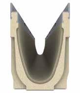
OCULTO 10
ULMA Linear Drainage Channel type OCULTO10: External width 140 mm, inside diameter 100mm and overall height 140 mm to collect rainwater in 1 metre long units.
CHANNEL
GRATINGS
The channel does not have grating. Channel of one piece only.
ACCESS UNIT GRATING
SUMP UNITS
AOCULTO100S + AU100
ACCESS UNIT
HPR100KCAM polymer concrete grating is locked on the AOCULTO 100S sump unit and OCULTO 100RM maintenance element using a locking bar.
SUMP UNITS
AOCULTO100S+AU100
AU200S+A200I+A200B
HYDRO
SYSTEM
Secondary streets, squares, playgrounds, schools, parks, gardens, etc.
Polypropylene drainage channels for pedestrian use and occasional car traffic, for areas with low hydraulic requirements.
Load Class up to A15
EN-1433 Standard
HYDROKIT
Full LM consist of 1 composite linear drainage channel ULMA, to collect rainwater, type HYDROKITH65, external width 130mm, internal width 100mm and overall height 65mm. 1 Units of galvanised Steel Normal Slotted (Runway) grating, type GN100UOA, up to A-15 load class, according to EN-1433 Standard. Channel - grating locking system “click” type
CHANNELS
Every channel has two preformed side knockouts for T, L and cross connections.
CLOSED END CAP LEAF GUARD
Slotted Long. Slotted Long. Slotted Slotted
HYDROMINI
(1) Every channel has two preformed side knockouts for T, L and
HYDROMINIPLUS
ULMA Linear Drainage Channel , type HYDROMINIPLUS: External width 132mm; Internal width 100mm and overall height 84mm, to collect rain water in 1 metre long units. The locking system consists of 2 screws per metre.
(1) Every channel has two preformed side knockouts for T, L and cross connections.
Load Class up to C250 EN-1433 Standard
HYDRO
ULMA Linear Drainage Channel , type HYDRO: External width 138mm; Internal width 100mm and overall height 134mm, to collect rain water in 1 metre long units. Locking system consists of locking bar and screws.
CHANNELS
GRATINGS
Load Class up to C250 EN-1433 Standard
HYDRO PLUS
ULMA Linear Drainage Channel, type HYDROPLUS: External width 138mm; Internal width 100mm; and overall height 148mm, to collect rain water in 1 metre long units. Locking system consists of locking bar and screws.
CHANNELS
Available in stainless steel, consult design
HYDRO 250
CHANNELS
* Available in stainless steel, consult design ULMA Linear Drainage Channel, type HYDRO: External
Load Class up to C250 EN-1433 Standard
HYDRO250PLUS
ULMA Linear Drainage Channel , type HYDRO: External width 266mm; Internal width 200mm; and overall height 185mm, to collect rain water in 1 metre long units. Locking system consists of locking bar and screws.
CHANNELS
GRATINGS
Slotted Mesh
* Available in stainless steel, consult design
HOW TO FIX
DRAINAGE
SYSTEM MULTIV+
Pedestrian areas, commercial areas, and car parks for all types of vehicles.
DRAINAGE EVOLUTION
The evolution of R&D processes and our 20+ years of experience in drainage solutions has enabled us to develop a new line of products better suited to market needs, providing in a single system the advantages of our other lines: the economy of the SELF system, the low heights of the MINI range, the 8-point fastening of the F line and the option of presloped, cascaded or mixed slope provided for by the U and UK systems.
The MULTIV+® is available in different heights, and up to a load class of D400.
ADVANTAGES OF THE MULTIV+ SYSTEM
01. MULTIV+ OPTIMIZED V-SHAPED SECTION
Especially designed for channel runs with no longitudinal slope
+ Higher speed with lower flows
+ Bigger capacity for extreme flows
The V-shaped design of the MULTIV+® channels has been developed to drain water faster, improving the self-cleaning effect of the channel. Its optimized cross section, larger than the traditional V-sections currently available on the market, provides bigger hydraulic capacity for extreme flow situations.
The fast and boltless ULMA Rapidlock® fastening system makes possible to connect the grating to the channel body quickly, safely and practically effortlessly.
REAL thickness of 2+2 mm, as required by EN-1433 Standard. No breaking protective zinc layer. Avoids water accumulation, preventing corrosion.
OPTIMIZED V-SHAPE
CHANNELS
MULTIV+100
ULMA Linear Drainage Channel, type MULTIV+ R100G; External width 136 mm, Internal width 100 mm, with overall heights between 80 and 300 mm; suitable for cascade-type slopes to collect rainwater; sections 1 LM in length; optimized V-shape with self-cleaning effect; especially designed for channel runs with no longitudinal slope; galvanised steel or ductile iron edges (2) for lateral protection; Either Rapidlock® boltless system or screw-fastened. 8 locking points per linear metre.
Vert. and horiz. outlets on order.
U shaped section.
Available channels with blocking screws (Code: R100F).
To install in the changes of height with cascaded slope.
TCR100G40MMA TCR100MF40MMA
Load Class up to D400 (1) EN-1433 Standard
ULMA Linear Drainage Channel, type MULTIV+ R150G; External width 186 mm, Internal width 150 mm, with overall heights between 80 and 320 mm; suitable for cascade-type slopes to collect rainwater; sections 1 LM in length; optimized V-shape with self-cleaning effect; especially designed for channel runs with no longitudinal slope; galvanised steel or ductile iron edges (2) for lateral protection; Either Rapidlock® boltless system or screw-fastened. 8 locking points per linear metre.
CHANNELS
* Vert. and horiz. outlets on order.
** U shaped section.
*** Available channels with blocking screws (Code: R100F).
MULTIV+150
GRATINGS LOCKING SYSTEM
(1) Available in stainless steel, consult design (1) Integrated into the channel (2) Supported
SUMP UNITS
SLOPE DESIGNS
BUCKET
MULTIV+150
END CAPS
Open Closed
R150GH8
R150GH12
R150G00R R150MFG00R
R150G10R R150MFG10R
GALVANISED STEEL - - - TR150H8C
POLYMER CONCRETE -
GALVANISED STEEL
R150G20R R150MFG20R
R150G30R R150MFG30R
*End caps also available with stainless steel edge. (1) Galvanised steel edge (2) Ductile Iron edge
To install in the changes of height with cascaded slope.
Security lock
Code Units x channel
BLOQPRG18020 8
Load Class up to D400 (1) EN-1433 Standard
OPTIMIZED V-SHAPE
CHANNELS
ULMA Linear Drainage Channel, type MULTIV+ R200G, External width 236 mm, Internal width 200 mm, with overall heights between 80 and 370 mm; suitable for cascade-type slopes to collect rainwater; sections 1 LM in length; optimized V-shape with self-cleaning effect; especially designed for channel runs with no longitudinal slope; galvanised steel edges (2) for lateral protection; Either Rapidlock® boltless system or screw-fastened. 8 locking points per linear metre.
* Vert. and horiz. outlets on order.
** U shaped section.
*** Available channels with blocking screws (Code: R200F).
(1) For cross-drainage in heavy traffic areas, we recommend our KOMPAQDRAIN® system. (2) Available Range in Stainless Steel. (Code: R200GX).
MULTIV+200
Heelproof Mesh Longitudinal Slotted Normal & Heelprof slotted
Single Slot
LOCKING SYSTEM
(1) Available in stainless steel, consult design (1) Integrated into the channel (2) Supported With blocking RAPIDLOCK®. Fast, boltless locking
SUMP UNITS
BUCKET
MULTIV+200
END CAPS
R200GH8
R200GH12
R200G000R R200MFG000R
R200G00R R200MFG00R
R200G10R R200MFG10R
R200G20R R200MFG20R
R200G30R R200MFG30R
*End caps also available with stainless steel edge. (1) Galvanised steel edge (2) Ductile Iron edge
Airports, warehouses, car parks for heavy vehicles...
Channels for heavy loads with attachment with 4 screws per grating, designed for heavy traffic areas. They are channels with galvanised steel profiles at the sides.
The maximum load class will be F-900 (depending on model).
ULMA Linear Drainage Channel type S200F: External width 206 mm; Internal width 150 mm and overall height between 102 and 162 mm to collect rainwater in 1 metre long units. Safe locking system consists of eight bolts per LM; Integrated galvanised steel edges for lateral protection.
SUMP UNITS
S 200 MF
ULMA Linear Drainage Channel type S200MF: External width 213 mm; Internal width 150 mm and overall height between 102 and 162 mm to collect rainwater in 1 metre long units. Safe locking system consists of eight bolts per LM; Integrated galvanised steel edges for lateral protection.
CHANNELS
Vert. outlets on order.
SUMP UNITS BUCKET
ULMA Linear Drainage Channel type S250F: External width 262 mm; Internal width 200 mm and overall height between 125 and 180 mm to collect rainwater in 1 metre long units. Safe locking system consists of eight bolts per LM; Integrated galvanised steel edges for lateral protection.
S 250 MF
ULMA Linear Drainage Channel type S250MF: External width 266 mm; Internal width 200 mm and overall height between 125 and 180 mm to collect rainwater in 1 metre long units. Safe locking system consists of eight bolts per LM; Integrated galvanised steel edges for lateral protection.
S 300 F
ULMA Linear Drainage Channel type S300F: External width 312 mm; Internal Width 250 mm and overall height between 120 and 210 mm to collect rainwater in 1 metre long units. Safe locking system consists of eight bolts per LM; Integrated galvanised steel edges for lateral protection.
CHANNELS GRATINGS
S 300 MF
ULMA Linear Drainage Channel type S300MF: External width 316 mm; Internal Width 250 mm and overall height between 120 and 210 mm to collect rainwater in 1 metre long units. Safe locking system consists of eight bolts per LM; Integrated galvanised steel edges for lateral protection.
CHANNELS GRATINGS
ULMA Linear Drainage Channel type S350F: External width 362 mm; Internal width 300 mm and overall height between 150 and 210 mm to collect rainwater in 1 metre long units. Safe locking system consists of eight bolts per LM; Integrated galvanised steel edges for lateral protection.
S 350 MF
ULMA Linear Drainage Channel type S350MF: External width 366 mm; Internal width 300 mm and overall height between 150 and 210 mm to collect rainwater in 1 metre long units. Safe locking system consists of eight bolts per LM; Integrated galvanised steel edges for lateral protection.
GRATINGS
AS200F / AS200MF*
SUMP UNITS
AS250F / AS250MF / AS350F / AS350MF
CIVIL-F
Motorways and airports, loading and unloading areas, ports...
Channels with attachment of the grating to the channel with 4 screws per grating, designed for heavy traffic areas and especially for sections where the grating is subject to large axial forces due to the manoeuvring and braking of vehicles, such as service stations, loading and unloading areas in ports and warehouses, airports, public roads,
The channels are reinforced with galvanised steel profiles at the sides. It is possible to incorporate a continuous
Available with modular cast iron grating with a load class of up to F900.
ULMA Linear Drainage Channel type F100K: External width 156 mm; Internal width 100 mm; Available with overall heights between 130 mm and 310 mm. Suitable for cascaded type slope to collect rainwater in 1 metre long units. Safe locking system consists of eight bolts per LM; Integrated galvanised steel edges for lateral protection. Load Class up to F900 EN-1433 Standard CHANNELS
SUMP UNITS
F 100MF
ULMA Linear Drainage Channel type F100MF: External width 163 mm; Internal width 100 mm; Available with overall heights between 130 mm and 310 mm. Suitable for cascaded type slope to collect rainwater in 1 metre long units. Safe locking system consists of eight bolts per LM; Integrated galvanised steel edges for lateral protection.
* Vert. and horiz. outlets on order.E
To install in the changes of height with cascaded slope.
Load Class up to F900 EN-1433 Standard
ULMA Linear Drainage Channel type F150K: External width 206 mm; Internal width 150 mm; Available with overall heights between 145 mm and 370 mm. Suitable for 2,5% presloped, cascaded or mixed slope, to collect rainwater, in 1 metre long units. Safe locking system consists of eight bolts per LM; Integrated galvanised steel* edges for lateral protection.
CHANNELS
GRATINGS
CONTINUOUS
* Also available with cast iron edges.E
HOW TO FIX
F 150 K
*Available up to 320 mm height. **The sump unit can be higher incorporating an intermediate unit.
OPEN END CAP
F150K00R T150K00A 160
Only applicable if 2 sump units are installed.
CLOSED END CAP
F150K10R T150K10A 160 T150K10C
F150K20R T150K20A 160
F150K30R T150K30A 160
T150K20C
T150K30C
To install in the changes of height with cascaded slope.
SLOPE DESIGNS
Load Class up to F900 EN-1433 Standard
F 150 MF
ULMA Linear Drainage Channel type F150MF: External width 213 mm; Internal width 150 mm; Available with overall heights between 220 mm and 370 mm. Suitable for cascaded slope, to collect rainwater, in 1 metre long units. Safe locking system consists of eight bolts per LM; Integrated galvanised steel* edges for lateral protection.
CHANNELS
* Vert. and horiz. outlets on order .
GRATINGS
SUMP UNITS
*Available up to 320 mm height. **The sump unit can be higher incorporating an intermediate unit.
* Also available with cast iron edges.E
HOW TO FIX
BUCKET
Only applicable if 2 sump units are installed.
F150K00R T150K00A 160
F150K10R T150K10A 160
F150K20R T150K20A 160
F150K30R T150K30A 160
STEP UNITS
F 150 MF
OPEN END CAP CLOSED END CAP Code CE150
To install in the changes of height with cascaded slope.
SLOPE DESIGNS
T150K00C
T150K10C
T150K20C
T150K30C
F 200 K
ULMA Linear Drainage Channel type F200K: External width 262 mm; Internal width 200 mm; Available with overall heights between 263 mm and 363 mm. Suitable for cascaded type slope to collect rainwater in 1 metre long units. Safe locking system consists of eight bolts per LM; Integrated galvanised steel edges for lateral protection.
* Vert. and horiz. outlets on order.STE
Only applicable if 2 sump units are installed. * The sump unit can be higher incorporating an intermediate unit.
F 200 MF
ULMA Linear Drainage Channel type F200MF: External width 266 mm; Internal width 200 mm; Available with overall heights between 263 mm and 363 mm. Suitable for cascaded type slope to collect rainwater in 1 metre long units. Safe locking system consists of eight bolts per LM; Integrated galvanised steel edges for lateral protection.
* Vert. and horiz. outlets on order.STE
AMF200 AMF200S + A200B
* The sump unit can be higher incorporating an intermediate unit.
** Only applicable if 2 sump units are installed.
ULMA Linear Drainage Channel type F250K: External width 312 mm; Internal width 250 mm; Available with overall heights between 150 mm and 650 mm. Suitable for 2,5% presloped, cascaded or mixed slope, to collect rainwater in 1 metre long units. Safe locking system consists of eight bolts per LM; Integrated galvanised steel* edges for lateral protection.
CHANNELS
• High hydraulic capacity.
• Self-cleaning effect.
• Minimum maintenance. FIRST POLYMER CONCRETE CHANNEL WITH PRESLOPED OF 2,5% ON THE MARKET
* Also available with cast iron edges.
F 250 K
SUMP UNITS
* The sump unit can be higher incorporating an intermediate unit. ** Available up to 400 mm height.
To install in the changes of height with cascaded slope.
F 250 MF
ULMA Linear Drainage Channel type F250MF: External width 316 mm; Internal width 250 mm; Available with overall heights between 150 mm and 650 mm. Suitable for cascaded slope, to collect rainwater in 1 metre long units. Safe locking system consists of eight bolts per LM; Integrated galvanised steel edges for lateral protection.
CHANNELS
* *Vert. outlets on order.
GRATINGS
SUMP UNITS
AMF250 AMF250S + A250B
* The sump unit can be higher incorporating an intermediate unit. ** Available up to 400 mm
BUCKET
F 250 MF
OPEN END CAP
F250MF00R T250K00A 200
F250MF10R T250K10A 200
F250MF20R T250K20A 200
F250MF30R T250K30A 200
F250MF40R T250K40A 200
STEP UNITS
To install in the changes of height with cascaded slope.
SLOPE DESIGNS WITHOUT SLOPE
CLOSED END CAP
T250K00C
T250K10C
T250K20C
T250K30C
T250K40C
F 300 K
ULMA Linear Drainage Channel type F300K: External width 362 mm; Internal width 300 mm; Available with overall heights between 300 mm and 750 mm. Suitable for cascaded type slope to collect rainwater in 1 metre long units. Safe locking system consists of eight bolts per LM; Integrated galvanised steel edges for lateral protection.
CHANNELS
* Vert. outlets on order.
GRATINGS
SUMP UNITS
F 300 MF
ULMA Linear Drainage Channel type F300MF: External width 366 mm; Internal width 300 mm; Available with overall heights between 300 mm and 750 mm. Suitable for cascaded type slope to collect rainwater in 1 metre long units. Safe locking system consists of eight bolts per LM; Integrated galvanised steel edges for lateral protection.
CHANNELS
* Vert. outlets on order.
AMF300
F 400K
ULMA Linear Drainage Channel type F400K: External width between 462 mm and 494 mm; Internal width 400 mm; Available with overall heights between 400 mm and 700 mm to collect rainwater in 1 metre long units. Safe locking system consists of eight bolts per LM; Integrated galvanised steel edges for lateral protection.
*Vert. outlets on order.
*The sump unit can be higher incorporating an intermediate unit.
F 400MF
ULMA Linear Drainage Channel type F400MF: External width between 466 mm and 494 mm; Internal width 400 mm; Available with overall heights between 400 mm and 700 mm to collect rainwater in 1 metre long units. Safe locking system consists of eight bolts per LM; Integrated galvanised steel edges for lateral protection.
SUMP
*The sump unit can be higher incorporating an intermediate unit.
A monolithich system specially designed for areas with high traffic density by ULMA Architectural Solutions, specialists in drainage system, this novel compact channel made of polymer concrete, is suitable up to load class F900, according to standard EN-1433.
Motorways, airports, service stations and other intense traffic areas require high drainage and maximum safety, requirements to which KOMPAQDRAIN® responds with a combination of features that make it unique on the market. These channels offer different surfaces according to its use.
KOMPAQDRAIN® ADVANTAGES
Directional elements
Drive water inwards, increasing intake.
Long-lasting and resistant
It is manufactured in polymer concrete, an anti-corrosive material, which offers great durability and exceptional resistance. Suitable to all class of loads.
Channel and grating form a one-piece unit, ensuring greater rigidity. Ideal for areas with maximum safety requirements.
Non - slippery surface
Special geometry to improve the grip.
Self-cleaning
Quick installation
Its compactness enables an easier and faster installation, reducing significantly the associated costs and maintenance.
Maximum security
Motorways, airports, service stations and other intense traffic areas require maximum safety, requirements to which KOMPAQDRAIN® responds presenting the channel and grating in one piece. It is compact
Its “V” optimized shape for greater hidraulic eficiency, avoid dirt blockage and ensures an efficient selfcleaning effect.
ACCES UNIT
Stainless steel, GALVANISED steel or ductile iron edges available
Perimetral preformed groove to facilitate joint sealing in 360º
Both sides pre-markings for L, T and + connections
Both sides premarking for horizontal outlets with rapid opening geometry
Pre-marking for vertical outlet with rapid opening geometry ( at register unit´s bottom )
MAX FLOW® SYSTEM
The original curved design of the inlets, together with the non-slip surface and water router, achieve the novel Max Flow® effect, increasing the water speed and the drainage capacity. Moreover, the progressive widening of the orifices helps the waste pass through more easily. Therefore KOMPAQDRAIN® can drain the same volume of water with a smaller channel.
KOMPAQDRAIN® meets all requirements of the EN-1433 international standard of quality and reliability.
CURVED DESIGN OF THE INLETS
IT INCREASES THE WATER ENTRY SPEED AND THE DRAINAGE CAPACITY
PROGRESSIVE WIDENING TO PREVENT DIRT BLOCKAGE
KOMPAQDRAIN® OVERVIEW
Both sides premarking for horizontal outlet with rapid opening geometry
Perimeter preformed groove to facilitate joint sealing in 360º
Different options of male and female connectors
Male and female horizontal/vertical alignment system
Pre-marking for vertical output with rapid opening geometry ( at register unit´s bottom ) Optional NBR elastomer triplelipped joint
Intermediate sump unit for deeper heights
Base sump unit with reversible position: Ø200mm front outlet and Ø200mm and Ø300mm lateral outlets
KOMPAQ 100 CITY
Linear Drainage Channel model ULMA KompaqDrain® City KVDH100, with an integral grating, presented in onepiece and manufactured by high resistant Polymer Concrete. Vandal – proof and corrosion resistant. Load class up to D-400, for all type of vehicles crossing and with reduced capture holes of 8 mm. With “V” optimized shaped and capture holes with MAX-FLOW® geometry: self-cleaning effect at a low flow, increase at maximum flow and positive opening in order to avoid dirt blockage, for areas without slope. Active surface for cutting of water sheet and for its driving to uptake holes and with non-slippery protuberances. Male and female horizontal and vertical alignment and perimeter preformed groove to facilitate joint sealing in 360º.
The access unit and the sump unit include: cast iron grating FNHX100FTDM, lateral preforms for horizontal outlets on each side and lateral preforms for connections in T, L and in cross.
CHANNELS
* Standard cast iron edges, GALVANISED and stainless steel edges available.
** The Sump unit can be higher incorporating an intermediate unit of 260mm. AKVD100I. *** More info about sump units and registers on page 150
Load Class up to D400 EN-1433 Standard
KOMPAQ 150
CITY
Linear Drainage Channel model ULMA KompaqDrain® City KVFDH150, with an integral grating, presented in one-piece and manufactured by high resistant Polymer Concrete. Vandal – proof and corrosion resistant. Load class up to D-400, for all type of vehicles crossing and with reduced capture holes of 13 mm. With “V” optimized shaped and capture holes with MAX-FLOW® geometry: self-cleaning effect at a low flow, increase at maximum flow and positive opening in order to avoid dirt blockage, for areas without slope. Active surface for cutting of water sheet and for its driving to uptake holes and with non-slippery protuberances. Male and female horizontal and vertical alignment and perimeter preformed groove to facilitate joint sealing in 360º.
The access unit and the sump unit include: cast iron grating FNHX150FTDM, lateral preforms for horizontal outlets on each side and lateral preforms for connections in T, L and in cross.
CHANNELS
ACCESS UNIT
* Standard cast iron edges, galvanised and stainless steel edges available.
** The Sump unit can be higher incorporating an intermediate unit of 380
AKVF150I *** More info about sump units and registers on page 151
KVFDH150.10R
KVFDH150.20R
KVFDH150.30R
TKVFDH150.10RC -
TKVFDH150.10RAJ 110
TKVFDH150.20RC -
TKVFDH150.20RAJ 110
TKVFDH150.30RC
TKVFDH150.30RAJ 110
Load Class up to D400 EN-1433 Standard
KOMPAQ 150
TRAFFIC
Linear Drainage Channel model ULMA KompaqDrain® Traffic KVFD150, with an integral grating, presented in onepiece and manufactured by high resistant Polymer Concrete. Vandal – proof and corrosion resistant. Load class up to D-400, for all type of vehicles crossing. With “V” optimized shaped and capture holes with MAX-FLOW® geometry: self-cleaning effect at a low flow, increase at maximum flow and positive opening in order to avoid dirt blockage, for areas without slope. Active surface for cutting of water sheet and for its driving to uptake holes and with non-slippery protuberances. Male and female horizontal and vertical alignment and perimeter preformed groove to facilitate joint
The access unit and the sump unit include: cast iron grating FNX150FTDM, lateral preforms for horizontal outlets on each side and lateral preforms for connections in T, L and in cross.
CHANNELS
ACCESS UNIT
* Standard cast iron edges, galvanised and stainless steel edges available.
SUMP UNITS
Sump Unit Code
The Sump unit can be higher incorporating an intermediate
More info about sump units and registers on page 151
KVFD150.10R
KVFD150.20R
TKVFD150.10RCTKVFD150.10RAJ 110
TKVFD150.20RCTKVFD150.20RAJ 110
KVFD150.30R TKVFD150.30RCTKVFD150.30RAJ 110
TCKVFD150.10RFFA
TCKVFD150.30RMMA
Load Class up to E600
EN-1433 Standard
KOMPAQ 150
INDUSTRY
Linear Drainage Channel model ULMA KompaqDrain® Industry KVE150, with an integral grating, presented in one-piece and manufactured by high resistant Polymer Concrete. Vandal – proof and corrosion resistant. Load class up to E-600 with surface design without protuberances to avoid vibrations in crossing vehicles, 30 x 25 mm uptake holes. With “V” optimized shaped and capture holes with MAX-FLOW® geometry: self-cleaning effect at a low flow, increase at maximum flow and positive opening in order to avoid dirt blockage, for areas without slope. Active surface for cutting of water sheet and for its driving to uptake holes. Male and female horizontal and vertical alignment and perimeter preformed groove to facilitate joint
The access unit and the sump unit include: cast iron grating FNX150FTEM, lateral preforms for horizontal outlets on each side and lateral preforms for connections in T, L and in cross.
CHANNELS
* Standard cast iron edges, galvanised and stainless steel edges available.
** The Sump unit can be higher incorporating an intermediate unit
*** More info about sump units and registers on page 151
Load Class up to F900
EN-1433 Standard
KOMPAQ 150
Linear Drainage Channel model ULMA KompaqDrain® Civil KVF150, with an integral grating, presented in one-piece and manufactured by high resistant Polymer Concrete. Vandal – proof and corrosion resistant. Load class up to F-900, for heavy loads. With “V” optimized shaped and capture holes with MAX-FLOW® geometry: self-cleaning effect at a low flow, increase at maximum flow and positive opening in order to avoid dirt blockage, for areas without slope. Active surface for cutting of water sheet and for its driving to uptake holes and with non-slippery protuberances. Male and female horizontal and vertical alignment and perimeter preformed groove to facilitate joint sealing in 360º.
The access unit and the sump unit include: cast iron grating FNX150FTFM, lateral preforms for horizontal outlets on each side and lateral preforms for connections in T, L and in cross.
ACCESS UNIT
* Standard cast iron edges, galvanised and stainless steel edges available.
CHANNELS SUMP
The Sump unit can be higher incorporating an intermediate
More info about sump units and registers on page 151
Linear Drainage Channel model ULMA KompaqDrain® City KVFDH200 with an integral grating, presented in one-piece and manufactured by high resistant Polymer Concrete. Vandal – proof and corrosion resistant. Load class up to D-400, for all type of vehicles crossing and with reduced capture holes of 16mm. With “V” optimized shaped and capture holes with MAX-FLOW® geometry: self-cleaning effect at a low flow, increase at maximum flow and positive opening in order to avoid dirt blockage, for areas without slope. Active surface for cutting of water sheet and for its driving to uptake holes and with non-slippery protuberances. Male and female horizontal and vertical alignment and perimeter preformed groove to facilitate joint sealing in 360º.
The access unit and the sump unit include: cast iron grating FNX200FTDM, lateral preforms for horizontal outlets on each side and lateral preforms for connections in T, L and in cross. CITY
CHANNELS
* Standard cast iron edges, galvanised and stainless steel edges available.
SUMP
** The Sump unit can be higher incorporating an intermediate unit of 380
AKVF200I. *** More info about sump units and registers on page 152
Channel Code Ø mm
KVFDH200.10R
KVFDH200.30R
KVFDH200.50R
TKVFDH200.10RC -
TKVFDH200.10RAJ 160
TKVFDH200.30RC -
TKVFDH200.30RAJ 200
TKVFDH200.50RC -
Channel
KVFDH200.10R
KVFDH200.30R
KVFDH200.50R
TCKVFDH200.10RFFA
TCKVFDH200.10RMMA
TCKVFDH200.30RFFA
TCKVFDH200.30RMMA
TCKVFDH200.50RFFA
TCKVFDH200.50RMMA
KOMPAQ 200
TRAFFIC
Linear Drainage Channel model ULMA KompaqDrain® Traffic KVFD200, with an integral grating, presented in one-piece and manufactured by high resistant Polymer Concrete. Vandal – proof and corrosion resistant. Load class up to D-400, for all type of vehicles crossing. With “V” optimized shaped and capture holes with MAX-FLOW® geometry: self-cleaning effect at a low flow, increase at maximum flow and positive opening in order to avoid dirt blockage, for areas without slope. Active surface for cutting of water sheet and for its driving to uptake holes and with non-slippery protuberances. Male and female horizontal and vertical alignment and perimeter preformed groove to facilitate joint sealing in 360º.
The access unit and the sump unit include: cast iron grating FNX200FTDM, lateral preforms for horizontal outlets on each side and lateral preforms for connections in T, L and in cross.
CHANNELS
* Standard cast iron edges, galvanised and stainless steel edges available.
** The Sump unit can be higher incorporating an intermediate unit of 380 mm. AKVF200I. *** More info about sump units and registers on page 152
KVFD200.10R TKVFD200.10RCTKVFD200.10RAJ 160
KVFD200.30R TKVFD200.30RCTKVFD200.30RAJ 200
KVFD200.50R TKVFD200.50RC -
KVFD200.10R
KVFD200.30R
KVFD200.50R
TCKVFD200.10RFFA
TCKVFD200.10RMMA
TCKVFD200.30RFFA
TCKVFD200.30RMMA
TCKVFD200.50RFFA
TCKVFD200.50RMMA
Load Class up to E600 EN-1433 Standard
KOMPAQ 200
INDUSTRY
Linear Drainage Channel model ULMA KompaqDrain® Industry KVE200, with an integral grating, presented in one-piece and manufactured by high resistant Polymer Concrete. Vandal – proof and corrosion resistant. Load class up to E-600 with surface design without protuberances to avoid vibrations in crossing vehicles, 30 x 25 mm uptake holes.With “V” optimized shaped and capture holes with MAX-FLOW® geometry: self-cleaning effect at a low flow, increase at maximum flow and positive opening in order to avoid dirt blockage, for areas without slope. Active surface for cutting of water sheet and for its driving to uptake holes. Male and female horizontal and vertical alignment and perimeter preformed groove to facilitate joint sealing in 360º.
The access unit and the sump unit include: cast iron grating FNX200FTEM, lateral preforms for horizontal outlets on each side and lateral preforms for connections in T, L and in cross.
CHANNELS
* Standard cast iron edges, galvanised and stainless steel edges available.
** The Sump unit can be higher incorporating an intermediate unit of 380 mm. AKVF200I. *** More info about sump units and registers on page 152
Load Class up to F900
EN-1433 Standard
KOMPAQ 200
Linear Drainage Channel model ULMA KompaqDrain® Civil KVF200, with an integral grating, presented in one-piece and manufactured by high resistant Polymer Concrete. Vandal – proof and corrosion resistant. Load class up to F-900 for high loads. With “V” optimized shaped and capture holes with MAX-FLOW® geometry: self-cleaning effect at a low flow, increase at maximum flow and positive opening in order to avoid dirt blockage, for areas without slope. Active surface for cutting of water sheet and for its driving to uptake holes and with non-slippery protuberances. Male and female horizontal and vertical alignment and perimeter preformed groove to facilitate joint sealing in 360º.
The access unit and the sump unit include cast iron grating FNX200FTFM, lateral preforms for horizontal outlets on each side and lateral preforms for connections in T, L and in cross.
* Standard cast iron edges, galvanised and stainless steel edges available.
CHANNELS SUMP
The Sump unit can be higher incorporating an intermediate unit
More info about sump units and registers on page 152
Possibility
SUMP UNITS
SUMP UNITS
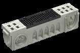
SLOT
The SLOT Drainage is part of an integral system, consisting of a discrete slot, a channel body and an access unit for an optimal maintenance of the drainage system. It is an inverted “T” or “L” shaped grating model, that stands out mainly for its aesthetics, since it integrates perfectly in the pavement (either concrete, paving stone or tiles) achieving a total blend with the urban landscape. Supports a load class up to D-400 according to Standard EN1433.
GRATINGS CLASSES
The grating can be either single or double slot for greater hydraulic efficiency, and offset to install close to walls.
SINGLE SLOT
Aesthetic solution.
Same solution with greater hydraulic capacity.
Ideal solution for areas near walls.
MATERIAL
Available in GALVANIZED STEEL as well as in STAINLESS STEEL (AISI 304 and AISI 316L) for the most demanding of hygiene.
Please consult our technical department with any queries regarding the application of materials and installation.
DOUBLE SLOT
OFFSET SLOT GRATE
DRAINAGE SYSTEM
MAINTENANCE
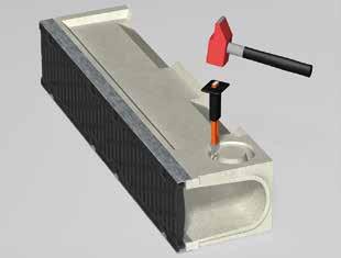
Steps to follow for the correct removal of the access unit and cleaning of the drainage system.
1. Identify the access unit, insert the two rods from the opening of the slot and turn.
2. Lift the access unit with the bars and set aside.
3. Remove the bucket located in that grating.
4. Empty and clean the bucket before placing it again.
INSTALLATION DETAILS
URBAN PAVER
TRAFFIC
TRAFFIC
Load Class up to C250
Standard
URBAN
Slot grating in an inverted “T” shape that stands out for its aesthetic, since it integrates perfectly in the pavement (concrete, paving stone or tile) achieving a total blend with the urban landscape. It can be a single slot or a double slot for greater hydraulic efficiency. Supports a load class up to C-250 according to Standard EN1433.
GRATINGS
ACCESS UNITS
TRAFFIC
Inverted “L” shape slot grating that stands out for its aesthetic, since it integrates perfectly in the pavement (concrete, paving stone or tile) achieving a total blend with the urban landscape. It is especially designed to be installed in areas close to walls. Supports a load class up to D-400 according to Standard EN1433.
GRATINGS
*Customised options available
IRL200RODH200E18
GALVANISED STEEL
*Customised options available
BEACONS
CABLE DUCTS
DRAINAGE
SOLUTIONS FOR TRAMS
ELECTRICAL SUBSTATIONS
INDUSTRIAL SKIRTING
TRENCHES
RUNWAY
ULMA® DRAINAGE SYSTEM
INSTALLATION INSTRUCTIONS
Initial conditions 1.
The purpose of these instructions is to provide general information for successfully installing and operating ULMA Architectural Solutions’ channel systems. The construction details refer to specific soil conditions, meaning professional advice is recommended for particular soils and/or local circumstances. We have a team of professionals with extensive experience that can provide advice and a personalised service to our customers in this regard.
The construction details presented are generic and aim to cover the broadest range of construction options, all with the highest guarantees possible. However, this does not exempt the Designer or Project Managers from checking these construction recommendations and making sure they are compatible with the nature of the soil.
This guide provides the basic instructions to ensure the correct operation of the system. Additional reinforcement may be required in special cases or soils with different characteristics, increasing the concrete bedding section or even installing rebars.
Seek advice from the engineering department in order to determine the size of any rebars and how they should be configured. ULMA Architectural Solutions’ channelling system has been designed and tested under the stringent provisions of STANDARD EN1433, thus ensuring compliance with requirements for collecting and discharging surface water and absorbing loads generated on flooring. The following conditions must be met in order for the drainage channel system to work properly:
1. Correct design of the project
2. Proper on-site planning
3. Specialist installation
4. Regular maintenance
The following regulations apply to the installation of ULMA Architectural Solutions’ drainage systems:
• UNE EN 1433:2002 + DIN V 19580 “Drainage channel systems for circulation areas” with regard to classifying and installing the corresponding channel systems.
• Structural Concrete Instruction (EHE), mandatory according to Royal Decree 2661/1998 of 11 December.
• CE marking of drainage channel systems, according to Resolution of 12 June 2003, of the Directorate General of Technology Policy. State Journal no. 165 for harmonised standard EN 1433.
• Directive 89/106/EC on construction product marking.
• Technical Building Code According to Royal Decree 314/2006, of 17 March 2006, on overall appearance, and specifically Basic Health Document part 5.
General installation instructions 2.
2.1 PREPARATORY WORK
The soil must be in good condition, in order to avoid future problems of sinkage and breakage of the channels. The soil should be well compacted if there have been any earthworks, eliminating any soft areas.
The compaction level should be of over 90% of the Proctor standard test and a 95-100% degree of compaction will be required for airports and roads with intense, heavy traffic.
2.2. PREPARING THE TRENCH
Prepare the trench for the base. The trench should be excavated with levelling according to the slope in question, always taking into account dimensions X, Y, Z, as set out in the installation instructions for the channel used.
2.3. SUB-BASE CONCRETE LAYER
Install a sub-base concrete layer and/or a base waterproofing fabric for the channel’s foundations.
2.4. POSITIONING THE CHANNELS
Establish an alignment line and prepare the channels along the trench. Check that the arrow on the sides of the channels points to the water discharge point
Open the outputs, always drilling the perimeter of the pre-marked output every 5-6 cm or cutting with an angle grinder.
Pour the concrete (min. HM25) at the base of the trench, checking the thickness required in the relevant drawings, and position the channels before it starts to set. The choice of materials, especially the concrete, is determined by environmental conditions at the place of installation.
The channels must be fitted on the concrete base without leaving any gaps, taking into account the placement direction shown by the arrow moulded on the channel (=direction of flow).
Installation must begin at the lowest point, i.e. at the passage to the drain pipe or collector box, where appropriate.
Check the alignment along the trench.
See chapter 3.13 Sealing joints between channels in these Installation Instructions. This procedure does not guarantee total waterproofing of the drainage line, meaning a waterproofing layer must be provided under the channel when installing in places with high waterproofing requirements, such as petrol stations or roofs of buildings. See chapter 3.4. Channels in places with high waterproofing requirements in these Installation Instructions.
2.5. CONCRETE BEDDING
Before pouring the concrete for the reinforcement bedding, fit timber battens or protect the gratings with plastic in the channels, thus preventing deformation that will prevent the gratings from being installed.
Pour the concrete through the sides of the channel, making the bedding as shown in the installation drawing.
It is very important to lay both layers within a reasonable time in order to ensure adhesion where two layers of concrete meet.
Where necessary, the “Y” measurement for the side height of the stabilising base relative to the channel body (as shown in the installation details established by ULMA Architectural Solutions) should be adapted on site, in accordance with the construction height of the channel body and the thickness of the flooring that follows it.
If necessary, install the mesh and pour the entire concrete bedding at once.
2.6. POSITIONING THE GRATINGS
Secure the gratings using their fixing system, applying a tightening torque to prevent the grating from moving after vehicles have passed over it. Installing the right fixing system for each use is essential to ensure that the system works correctly. See fixing systems.
2.7. SAFETY MEASURES
The channels must be duly reinforced against horizontal loads for the duration of flooring work on the adjacent sides of the channel, e.g. by installing gratings on the channels (if not already installed).
Mechanical damage to the channels must be avoided when finishing the surfaces adjacent to the channel. The movement of soil compacting elements must therefore be studied in detail before, during and after installing the channel’s bedding.
Once finished, the flooring next to the channel must be 3 to 5 mm higher than the channel itself, including the thickness of the grating, and its surface must not cause any slippage.
Concrete bedding Channel Grating
3-5mm from the grating
Detail B Channel without edge
Detail A Channel with edge
Concrete bedding Channel
Grating
3-5mm from the edge
Special installation instructions 3.
3.2. CHANNELS IN FLOORING WITH PAVING STONES
3.1. EXPANSION AND CONTRACTION JOINTS
The Designer or Project Manager must draw up a suitable joints plan according to the construction details of the base slab and applicable standards and regulations, in order to avoid any tangential or perpendicular stress on the concrete bedding and channel assembly.
If the channels are installed on a concrete slab, expansion joints must be installed between the slab and the bedding in order to prevent expanding concrete from generating stresses on the sides of the channel.
Moreover, expansion joints must be installed whenever paving, slabs or asphalt are placed on top of a concrete slab, as described in the concrete installation instructions issued by ULMA Architectural Solutions.
DO NOT place expansion joints between the channel body and the adjacent flooring. Such joints must always be between the bedding and the adjacent flooring.
On concrete floors, installing contraction joints every 6 or 7 metres is recommended in order to avoid uncontrolled cracking of the floor.
All contraction joints running transversely to the channel must coincide with the joint between the channels in order to avoid generating tangential forces.
The joints between the channel body and large paving stones laid on a bed of sand must be filled in accordance with the installation details established by ULMA Architectural Solutions, and may use a high-strength material combined with cement or with a synthetic resin-based material, always in accordance with local requirements, in terms of load, strength, etc. Adhering the paving stones to the concrete means they will be an integral part of the channel. The size of the joint depends on the application instructions issued by the manufacturer.
3.3. GROOVED CHANNELS
The installation of channels with single-slot grating on stone and/or tiled pavements will require the use of a reactive type epoxy adhesive (R) in the joints between the paving stone and grating, as well as in the points indicated in the construction details for this type of installation.
3.4. CHANNELS IN SITES WITH HIGH WATERPROOFING REQUIREMENTS
Channels installed in places with high waterproofing requirements, such as filling stations, terraces, roofs, car parks, etc., must always be placed on a waterproofing layer and/or fabric, following the construction details for this type of installation.
3.5. EXTENDING THE CONCRETE
BEDDING
For better load distribution, we recommend extending the concrete bedding at the end of the channel section in longitudinal direction, as described below:
• Type of load A 15 - C 250 ≥ 15.0 cm;
• Type of load D 400/E 600 ≥ 25.0 cm;
• Type of load F 900 ≥ 50.0 cm
3.6. EXTREME
LOADS
Areas subject to extreme loads include: Container terminals; truck operating areas; truck entrances to sites; busy loading and unloading areas with heavy duty trucks, and similar.
We recommend ULMA F 100 K - F 400 K or ULMA KompaqDrain® channel systems in these cases.
3.7.
CHANNELS IN MOTORWAYS AND HIGHWAYS
ULMA’s KompaqDrain® system is the only valid system for areas that are transversal to traffic on motorways and highways.
3.8.
CHANNELS WITHOUT MESH
ULMA channels meet the requirements for load tests described in the standard, without the need for any reinforcements. Therefore, the minimum cross-sections required for installation do not require the use of reinforcements.
Reinforcements can be used to prevent any retraction of
the concrete bedding, thus ensuring the correct connection between the bedding and the channel in special situations of heavy loads or intense traffic. We recommend contacting the technical department if you have any doubts.
3.9.
ZINC-COATED MATERIAL
We recommend not installing zinc-coated products in areas where contact with corrosive agents, such as cleaning products, chlorides, sulphates, acids, bleaches, etc. cannot be ruled out (e.g. swimming pools or marine environments).
3.10. STAINLESS STEEL
During installation, products made of stainless steel must be adequately protected against ferrous oxide dust in the environment, sparks caused by cutting metals, etc. The surfaces should be cleaned at regular intervals to maintain their appearance and prevent corrosion. The type of stainless steel will be chosen in accordance with environment where it is to be installed (AISI 304 for normal environments and AISI316 for marine environments).
3.11.
CUTTING THE CHANNEL AND GRATING
All channel and grating elements can generally be cut to a suitable length on site. However, it should be remembered that at least one attachment point per grating should remain accessible. If necessary, remove the burrs from all cut metal edges and ensure there are no sharp edges. Mitre joints are achieved by cutting the channels to the desired angle and abutting them or joining them with resin. Bevelling channels for higher types of load (D400, E600 and F900) is NOT recommended. Mitre joints and couplings can be configured with connecting pipes.
3.12. MOULDED PREFORMS
In principle, vertical moulded preforms in polymer concrete will always be opened/hammered from inside to out. To do this, we recommend making a contour on the outside of the preform with boreholes, and hammering the weakened area with a mallet and chisel. Boreholes can be made with a hand drill.
3.13. SEALING JOINTS BETWEEN CHANNELS
PREPARING SURFACES
Cleaning: The polymer concrete substrate must be cleaned thoroughly before applying any of the sealing elements. The aim is to eliminate any elements that prevent direct contact between the sealing elements and the substrate.
All surfaces that are going to be in contact with the sealing elements must be cleaned (both the groove that will house the sealant and the two front faces of the channels to be joined).
There must be no dirt, dust, grease, oil or any other element wholly or partially covering the substrate and adversely affecting adhesion between the sealing elements and the substrate.
Priming: Applying a cleaning and activation product for priming is recommended once the sealing surfaces have been cleaned. There are specific products for each elastic sealant, which can be used to improve adhesion to the substrate.
It is usually enough to apply a coat of activating cleaner on the surfaces to be treated, and then leaving them to dry. This should be done using a brush, always following the manufacturer’s instructions.
APPLYING SEALANT
Either a single-component product or a two-component product can be applied for elastic sealing.
The recommended single-component elastic sealant cures thanks to environmental humidity, and therefore has a variable curing period, depending on the humidity present in the environment.
The two-component elastic sealant recommended for this application is as valid as the single-component product, the only difference being the extra work involved in uniformly mixing the components beforehand, and the fact that workability and application time are limited.
Single-component sealant: Using a single-component sealant is recommended if curing time is not a critical element; in this case, the curing process can be around 2-3 mm after 24-48 hours, always depending on environmental humidity, and it can be applied without first mixing the components.
Two-component sealant: Applying a two-component sealant is recommended if a short or independent curing period is required, in this case consisting of the sealing element itself plus a product that accelerates the curing reaction.
REMARKS
Any action carried out with the recommended products must always be in keeping with the relevant Instructions, Technical Data Sheets and Safety Data Sheets issued by the manufacturer.
The reliability and durability of the sealing solution depend on the specific conditions of each work site: conception and design, conditions, care taken during installation, use and maintenance, local climatological conditions, etc.
Since ULMA Architectural Solutions has no influence over these aspects and cannot guarantee a working life for this sealant solution, it shall not be in any way liable in this regard, with its work being limited simply to recommending a suitable commercial sealant product.
INSTALLATION
SELF System
PAVER ONTO A LOAD-BEARING SLAB SELF PAVER SELF
ASPHALT
A15 - B125 - C250
Surface course
Base layer
Compacted sub-base
Compacted ground
Asphalt
Base layer
Compacted sub-base
Compacted ground
* In case of an incorrect compactation of the soil, the concrete embracement must be made up to the pavement level.
A15 - B125 - C250 with slot grating
* In case of an incorrect compactation of the soil, the concrete embracement must be made up to the pavement level.
CONCRETE
Compacted sub-base
Compacted ground
Compacted sub-base
Compacted ground
A15 - B125 - C250 with slot grating
* In case of an incorrect compactation of the soil, the concrete embracement
PAVER ONTO A LOAD-BEARING SLAB
Base
Compacted
Compacted
ASPHALT
MINI System
PAVER MINI
ASPHALT MINI
In case of an incorrect compactation of the soil, the concrete embracement must be made up to the pavement level.
URBAN System
PAVER ONTO A LOAD-BEARING SLAB
ASPHALT
CONCRETE URBAN
Base
Compacted
Compacted
* In case of an incorrect compactation of the soil, the concrete embracement must be made up to the pavement level.
Compacted sub-base Compacted ground
A15 - B125 - C250 with slot grating
* In case of an incorrect compactation of the soil, the concrete embracement must be made up to the pavement level.
URBAN
Compacted
A15 - B125 - C250 with slot grating
PAVER ONTO A LOAD-BEARING SLAB
PAVER ONTO A LOAD-BEARING SLAB SPORT
CONCRETE
CONCRETE
SYNTHETIC PAVEMENT
HYDROKIT | HYDROMINI | HYDRO
HYDROMINIPLUS | HYDROPLUS
HYDRO250
HYDRO250PLUS
HYDRO System PAVER
Base
Compacted
Compacted
Base layer
Compacted sub-base
Compacted ground
A15 - B125 - C250 with slot grating * In case of an incorrect compactation of the soil, the concrete embracement
ASPHALT
Base layer
Compacted sub-base
Compacted ground
A15 - B125 - C250 * In case of an incorrect compactation of the soil, the concrete embracement
PAVER HYDROPLUS
A15 - B125 - C250 with slot grating
In case of an incorrect compactation of the soil, the concrete embracement must be made up to the pavement level.
ASPHALT HYDROPLUS
Surface course
Compacted sub-base Base layer
Compacted ground
CONCRETE
* In case of an incorrect compactation of the soil, the concrete embracement must be made up to the pavement level.
Block pavement
Compacted sub-base Base layer
Compacted ground
* In case of an incorrect compactation of the soil, the concrete embracement must be made up to the pavement level.
Surface course
Compacted sub-base Base layer
Compacted ground
* In case of an incorrect compactation of the soil, the concrete embracement must be made up to the pavement level.
CONCRETE HYDRO250
Compacted
PAVER
Compacted
ASPHALT
Compacted
Compacted
In case of
MULTIV+ System PAVER
PAVER ONTO A LOAD-BEARING SLAB
-
-
In case of an incorrect compactation of the soil, the concrete embracement must be made up to the pavement level.
ASPHALT
A15 - B125 - C250 with slot grating * In case of an incorrect compactation of the soil, the concrete embracement must be made up to the pavement level.
CONCRETE
CIVIL-S System
CIVIL-S
ASPHALT
CIVIL-S
CONCRETE
CIVIL-F System
Construction joint
ASPHALT
D400 - E600 - F900
Longitudinal to the traffic direction
Construction joint
CONCRETE
Expansion joint
Compacted ground
Construction joint
Concrete
Expansion joint
Compacted ground
D400 - E600 - F900
to the traffic direction
D400 - E600 - F900
Longitudinal to the traffic direction
Concrete slab
Base layer soporte
Compacted ground
D400 - E600 - F900
Transversal to the traffic direction
Concrete slab
Base layer soporte
Compacted ground
For heavy transversal traffic use always KompaqDrain channels.
F300 | F400
ASPHALT
D400 - E600 - F900
Longitudinal to the traffic direction
D400 - E600 - F900
Transversal to the traffic direction
CONCRETE
*Complies F900 load class without reinforcing wire mesh.
KOMPAQDRAIN System
PAVER
Base
Compacted sub-base
Compacted ground
* In case of an incorrect compactation of the soil, the concrete embracement must be made up to the pavement level.
Base
Compacted sub-base
Compacted ground
ASPHALT
Base
Compacted
Compacted ground
Longitudinal to the traffic direction
ASPHALT
A15 - B125 - C250
Transversal to the traffic direction
* In case of an incorrect compactation of the soil, the concrete embracement must be made up to the pavement level.
A15 - B125 - C250 - D400
Longitudinal to the traffic direction
ASPHALT
Concrete Bituminous joint
Surface course
Base layer
Compacted sub-base
Compacted ground
Concrete Bituminous
Compacted sub-base
Compacted ground
CONCRETE
Base layer soporte
Concrete slab Compacted ground
Concrete slab
Base layer soporte
Compacted ground
D400 - E600 - F900
Longitudinal to the traffic direction
*Complies load class without reinforcing wire mesh.
D400 - E600 - F900
Transversal to the traffic direction
D400 - E600 - F900
Longitudinal to the traffic direction
*Complies load class without reinforcing wire mesh.
D400 - E600 - F900
Transversal to the traffic direction
UNIQUE DETAILS
BESIDE KERB
In case of an incorrect compactation of the soil, the concrete embra-
ONTO A FLOOR FRAME
Asphalt Concrete slab
Isolation
Vapour
CONCRETE
Concrete
GENERAL CONDITIONS OF SALE
1. ORDERS
1.1. To avoid possible errors, orders must be sent signed and stamped to our sales technicians or our customer service department (SAC) by fax or email.
1.2. In the case of orders that include a special piece or custom drawing, they must be signed and stamped along with the other required information.
1.3. Ulma is not responsible for the choice of models and/or materials that are not suitable for the use or load indicated in our recommendations, which are included in our catalogue and on our website (www. ulmaarchitectural.com).
2. PRICES
2.1. The validity of the offer is indicated in the small print on the offer.
2.2. All prices are subject to the relevant VAT or tax.
2.3. ULMA may modify the prices without prior notice, and this document is a brochure with general information and in no case does it act as a contractual document.
3. ASSEMBLY
3.1. ULMA is not responsible for any material assembled without following the manufacturer’s installation instructions. These are available on our website: www.ulmaarchitectural.com.
3.2. For any technical information you can consult our technical department
4. SHIPMENTS
4.1. All freight costs shall be indicated in the offers and orders.
4.2. Any claim or incident must be notified to the corresponding commercial technician or to our customer service department within a maximum period of 72 HOURS, indicating the delivery note number and providing photographs demonstrating the reason for the incident.
4.3. Any claim or incident due to BREAKAGE of the material on receipt of the material MUST BE INDICATED ON THE CARRIER’S DELIVERY NOTE.
4.4. The material will be delivered on a lorry.
4.5. The unloading and means of unloading are at the customer’s expense.
4.6 No penalties shall be admitted for delays in the supplies, these periods are approximate and shall be indicated in the offers and orders.
5. PAYMENT TERMS
5.1 The terms of payment shall be agreed by both parties and shall be indicated in each offer and in each order.
5.2. For credit operations, and provided it is authorised by ULMA’s credit department, the maximum payment period shall not be greater than that indicated in Law 15/2010, of 5 July, published in Official State Gazette 10708 of 7 July. INSOLVENCY LAW
5.3. Repeated failure to meet payment deadlines shall result in the reduction or cancellation of the line of credit.
5.4. In the event of non-payment, ULMA reserves the right to process the payment collection through an independent company. As a first step, the supply of material for this customer shall be cut.
5.5. For new customers and individuals, payment shall be made in advance.
5.6. Withholding due to guarantee shall not be allowed.
5.7. No charges shall be accepted for handling payment documents.
6. RETURNS
6.1. ULMA Hormigón Polímero does not accept returns of material as indicated in all written offers.
7. CONTRACTS
7.1. No other type of contract dated after this agreement shall be accepted, nor shall any additional clauses that contravene those set out in this document.
7.2. If the customer is required to enter a contract, the contract must be entered before the order is processed, ULMA will not process any order until the contract is is in its possession, duly completed and signed by both parties.
8. JURISDICTION
8.1. Any lawsuit arising from the commercial relationship shall be resolved in the courts determined by ULMA.
8.2. The technical information contained in this document is the information in force at date of printing, therefore, in order to update this information, we recommend you visit our website ulmaarchitectural. com.
8.3. ULMA reserves the right to modify the specifications of any of its products without prior notice
ulmaarchitectural.com
Bº Zubillaga, 89 - Apdo. 20, 20560 Oñati (Gipuzkoa) Spain