The Complexity of Human Vision
By Keito Orii Grade 10 Human Vision

What is vision? Vision is something we take for granted, but it’s really a complicated process involving the perception of light (see Figure 1) – photons, by the eyes and then is converted into electrochemical signals that are processed in the visual cortex at the back of the brain.

Human vision is limited to what we consider optical wavelengths: 400-700nm. Some animals can see infrared (which we perceive only as heat) and many animals can see ultraviolet wavelengths. Deer, for example, can often see UV waves being reflected off of deer hunters’ clothing, even though they are wearing camouflage clothing. So hunters buy special laundry soap that will not leave any traces that reflect UV light. Cats and dogs don’t see much color. They have more receptors for light in their eyes (rod cells) compared to color receptors.
——————————————————————————————————
Figure 1 : The EM spectrum
Eye Anatomy
The retina in our eyes (Figure 2)


– the light sensitive cells at the back of the eye, contain rod cells and cone cells that are sensitive to particular wavelengths of light. The eye is comprised of the cornea which covers the lens in the front part of the eye. The iris, the colored portion of the eye, contains muscles that are responsible for widening and narrowing the pupil which is the circular opening in the center of the iris. The pupil dilates in dark conditions, and contracts in bright daylight. The lens behind the cornea focuses light onto the retina and changes the focal distance by changing its shape. When light goes through the front of the eye (Figure 3), it creates an inverted image on the retina. The energy from those photons gets converted into electrical impulses, and travels through the optic nerve to the visual cortex. Where the optic nerve is connected to the retina there is a blind spot, but we don’t notice this, because our brains fill in the details of that spot with information from the surrounding areas.
Figure 2 : The Front View of the Eye
Figure 3 : Side View of the Eyeball Showing Its Various Components
Color Theories
The first theory of color vision is the Young-Helmholtz trichromatic (or three-color) theory. This theory states that there are three types of cone cells in the retina that specialize in the three primary colors of light: red, green, or blue (Figure 4). From these three colors, humans can perceive all colors. The display you’re reading this article on uses the same three primary colors to create many colors for each pixel. Without fully functioning cone cells, some people can only perceive some of the colors in the world. At this point, you may be wondering why a mixture of red, green, and blue will create white, and how all the colors can be generated from just these three. Light is a subtractive mixture, not additive like paint colors.


Pictured at left is a prism (Figure 5), which separates white light into the different colors of the rainbow, by refraction, according to their different wavelengths. Red has the longest wavelength, while violet has the shortest. Thus the colors are always refracted in the same order, including in a rainbow, when sunlight is refracted through water droplets in the atmosphere.

The second stage of visual processing is the Opponent-Process Theory. Our brains process colors relative to what’s around them. Although the color of both the small squares are the same, they seem to be different because of the colors surrounding
Figure 4 : Mixing of Primary Colors of Lights
Figure 5 : The Separation of White Light Into a Rainbow Using Prism Refraction
them. Relativity makes the light color seem to be darker than the left color.

The color-negative image shown can be used to demonstrate an afterimage: an effect of fatigue that can occur from looking at the same color on the same part of the retina. The color positive/negative complements are: red/green, yellow/blue, and black/white. After focusing on the dot on the woman’s nose in Figure 7 for 60 seconds, focus your eyes on the dot in the square space to the right. You will see the opposite colors appear, and thus see a color-positive image.
How Our Brain Processes Light
Figure 6 : Visual Processing of Colors Is Relative
Figure 7 : A Color-Negative Image
The visual cortex is very large; it makes up more than one third of our cerebral cortex.. It’s in the back of our head. Much of the visual cortex and other areas of the brain have been mapped by psychologists using brain scans while subjects look at images

The vision from the right visual field of the right and left eye is processed in the left hemisphere of the brain. Conversely, the left visual information from the right and left eye is processed in the right hemisphere. As a result, each hemisphere's visual cortex views a different side of your visual field. In addition, each eye receives slightly different information because of the distance between your eyes, allowing our brain to create a 3dimensional representation of what we see.
Optical Illusions
There are many different reasons why what we see may be misleading. When the perceived size of the object remains the same even though its size changes in your retina, it is called size constancy. So we would say the distal stimulus remains the same even though the proximal stimulus appears to change. For example, we may perceive the moon as being larger when it’s near the horizon, because its size, relative to distant buildings, is quite large. Whereas, when the moon is overhead, there is nothing (except for tiny stars) to compare its size. Remember that perception is an active, but mostly unconscious process of organizing and interpreting sensations.
 Figure 9 : Size Constancy
Figure 8 : Left and Right Visual Fields Connected by the Optic Nerves
Figure 9 : Size Constancy
Figure 8 : Left and Right Visual Fields Connected by the Optic Nerves
References
1. How does refraction of light cause a rainbow to form? | Socratic. (n.d.). Socratic.org.
https://socratic.org/questions/how-can-refraction-make-a-rainbow-1
2. Kolb, H. (2011). Simple Anatomy of the Retina by Helga Kolb – Webvision. Utah.edu.
https://webvision.med.utah.edu/book/part-i-foundations/simple-anatomy-of-the-retina/
3. Li, S. (2022, August 27). Colors Are Relative. Medium. https://bootcamp.uxdesign.cc/colors-are-relative9599aab262a0
4. Martin, A. (2022, August 17). The electromagnetic spectrum. Online Learning College. https://online-learningcollege.com/knowledge-hub/gcses/gcse-physics-help/electromagnetic-spectrum/
5. Opponent Process Theory of Color Vision Video. (2020). Opponent Process Theory of Color Vision | Study.com. Study.com.
https://study.com/academy/lesson/opponent-process-theory-of-color-vision.html
6. Patel, H. (2018, September 24). Anatomy of the Human Eye. News-Medical.net. https://www.newsmedical.net/health/Anatomy-of-the-Human-Eye.aspx
7. Stephens, C. (2022, February 3). Quick Color Theory: Exploring the Color Wheel. The Beat: A Blog by PremiumBeat.
https://www.premiumbeat.com/blog/quick-color-theory-color-wheel/
8. Vision – Introduction to Psychology & Neuroscience. (n.d.). Digitaleditions.library.dal.ca.
https://digitaleditions.library.dal.ca/intropsychneuro/chapter/vision/
9. Visual Constancy. (n.d.). The Psych Apprentice. http://psychapprentice.weebly.com/psychology-lexicon/visualconstancy
10. Wandell, B., Dumoulin, S., & Brewer, A. (n.d.). Visual Cortex in Humans. Retrieved December 5, 2023, from
https://spinozacentre.nl/dumoulin/PDFs/Wandell-Encyclopedia-2009.pdf
11. Your Brain Develops The Negative – Webvision. (n.d.). https://webvision.med.utah.edu/2012/06/your-brain-develops-
the-negative/
What is CRISPR Cas9? How you can become Superman.
Mariyah Matawala Grade 11


Introduction:
The thought of humans being able to change their genetic buildup, change their DNA which makes them exactly who they are from their appearance to their health condition, seems only like a far-fetched dream. But not any longer, as the world is constantly in motion, and advancements are being made in every part of the world, the so-called far-fetched dream can become a reality.

1
The technology CRISPR, which enables gene editing, is most likely to alter the course of human history. Found originally in certain bacteria as an immune system response, it can now be used in humans to edit genes. CRISPR can locate a particular DNA sequence inside a cell modify that portion of DNA and bring certain changes in the human body (Bolt, 2019). This topic is prominent for discussion because CRISPR/Cas9 can dictate the future of the entire human species.
How is CRISPR used to edit human genes?
Today, the majority of medical treatments target faulty proteins linked to a disease; typically, these abnormal proteins result from a mutation in a patient's DNA that affects one or more specific genes. In the past, scientists have not been able to directly modify the genes to address the disease's underlying cause (“CRISPR/Cas9 | CRISPR,” 2022). Normally, when a piece of DNA is cut, it goes to its sister (which has an exact copy because we have 2 copies of the same gene) and copies the missing genetic information to build itself up. This is useful because, if scientists were to cut a gene inside a cell and give it a separate sequence to copy, which is identical to the gene being cut but with one simple change (this could be the letter T to an A to cure sickle cell disease), the broken DNA would copy the DNA provided as a template using a process called homology-directed repair (Bolt, 2019). Or scientists could target a specific gene
2
and insert their own piece of DNA, so a template wouldn’t be required called non-homologous end joining. If the gene is changed then the disease is cured (Guitart, 2016). But there are between 20-25 thousand genes, and the exact gene would need to be targeted, this is causing the problem (Bolt, 2019).
With CRISPR/Cas9, however, researchers can edit, remove, or fix certain regions of human DNA. The system comprises an enzyme called Cas9 that cuts DNA and a guide RNA whose sequence tells Cas9 where in the DNA to do the edit. The combination formed by Cas9 and the guide RNA may be quickly and precisely directed to the desired location in the DNA. When the complex detects and attaches to a gene close to the target spot, the CRISPR Cas9 gene editing procedure starts. As a result, the DNA begins to unwind, enabling the guide RNA to pair with the precise target sequence in the DNA. In the event that the sequences are perfectly paired, Cas9 breaks the DNA, creating a double-strand break (“CRISPR/Cas9 | CRISPR,” 2022). Now that the exact location of the DNA is broken, the natural repair will take place, but the DNA will be tricked. Instead of copying the gene from its sister, it will replicate the DNA provided by a template (homology-directed repair) (Bolt, 2019). Another solution is for a programmed DNA to be inserted after the cut (non-homologous end joining) (“CRISPR/Cas9 | CRISPR,” 2022). This
3
will cause the faulty gene to be corrected and the disease to be cured. This can give us the ability to change any gene in the human genome, therefore, changing the human itself.
Germline Gene Editing & Ethics
In a laboratory dish, germline gene editing entails changing particular genes in an egg, sperm cell, or early embryo. In gamete cells, defective DNA within a gene can be removed, disrupted, altered, or corrected through the process of germline gene editing (Ethical Issues: Germline Gene Editing, 2020). If gene edits are made in somatic cells, then the edits can not be passed on to future generations. However, if there were gene changes made in gamete cells then the edited genes can be passed down to future generations (Bolt 2019).

4
This raises the ethical question of whether people should be allowed to make genetic changes for future generations.
One argument is that the technology of germline editing may be of relevance to parents who have or carry a defective gene. Early embryos contain very few cells, therefore there would be far fewer cells to target for editing. A child with many cells that have the desired edit may be born if those few modified cells divide repeatedly as the embryo develops. An alternative to editing the embryo would involve modifying the parent's gamete cells (egg or sperm) with the intention of creating a fertilized embryo through in vitro fertilization (IVF) that carries the desired genetic modification (Ethical Issues: Germline Gene Editing, 2020). By editing the DNA of the embryo or the gamete cells, the child will have a better life to live. The child won’t be carrying any harmful diseases and be at risk of deteriorated health, it could live a healthy life and have its children live a life without pain and suffering.
However, due to the fact that genetic disorders are inherited, therapeutic germline gene editing could have an impact across several generations after the treated embryo develops, gives birth, and passes on the altered genes to its offspring. Within the lifetime of the treated patient, the possible benefits and potential dangers for both the edited individual and the greater population
5
may not be fully understood or appreciated, and many generations would need to be examined to comprehend the long-term impacts. This is the main reason why In the United States, Europe, the United Kingdom, China, and many other nations, germline gene editing is not permitted for clinical use (Ethical Issues: Germline Gene Editing, 2020).
Nevertheless, the risks are still present. One of them being the off-target effect. Off-target effects are undesirable genetic alterations that take place in addition to the desired genetic change. All methods of gene editing have the potential to introduce off-target alterations at parts of the genome other than the desired spot. Clinical germline gene editing of very early embryos carries the risky potential for off-target effects to negatively affect a variety of organs and bodily functions. Since the goal of editing an embryo for clinical application is to ensure the desired edit is present in every cell as the embryo develops, it is also possible for potentially harmful offtarget effects to be present in some or all cells (“CRISPR/Cas9 | CRISPR,” 2022).
Designer Babies & Ethics
A scientist named John Zang who owns the 4th biggest fertility clinic in the US started a company named Darwin Life which supports and promotes the idea of designer babies. This idea started way back in 1972 with the name of baby shopping in which parents could change the IQ
6
of their baby, the shape of their face, the color of their eyes, their height, their characteristics, and more things beyond imagination (Bolt, 2019). In 1972 it was merrily considered sci-fi and unrealistic, however now, it is realistic.
The process would work the same way that germline gene editing does on embryos, but instead of editing DNA to prevent diseases, DNA would be edited for parents’ satisfaction. A child that would be born from an embryo, sperm, or egg that had undergone genetic modification is referred to as a "designer baby." Every cell in that child's body would undergo alterations, which would then be passed on to all of the child's siblings and cousins. Heritable genome editing has come to be used to describe this process. Currently, there is a heated discussion about whether heritable genome editing should be legalized. On the one hand, about 40 nations have already passed legislation against it, and 29 more have ratified an international agreement that forbids it. (Darnovsky, 2020).
This would open up a brand-new market for the fertility industry. It would be a completely new area of peer pressure for parents. Children born from genetically altered embryos would be seen as superior since they would be stronger, wiser, and more developed.
7
As technology develops every single day, more ways of using CRISPR are discovered and perfected. Using CRISPR to treat the diseases of people who are already developed could end so much suffering and better the lives of billions. However, with this gift comes a side of fear; people would use CRISPR on them for more than just to cure diseases but also for reasons to make themselves more attractive, productive, or superior. Nevertheless, there is another side to editing this gene in, cancer causes a lot of pain, especially terminal cancer. If that gene was changed, that person could live the last days of their life without pain (Bolt, 2019).
Two perspectives could be seen with each edit, which is why regulation needs to be enforced if CRISPR becomes widely available to edit all genes. We would have the power to change a single gene that could make us all more muscular, smarter, or active but should that really be made universally available?
Conclusion
In conclusion, CRISPR truly is a marvelous technology that can greatly revolutionize the world. But like all improvements, it has its equal share of pros and cons. It is alluring to think about all the great things it can do for humankind, but terrifying to imagine the disastrous future it could cause. Honestly, are we ready for CRISPR to enter our lives? Is the world ready? Is playing with
8
nature a risk we are willing to take, a direction worth going to where there is no turnback? It is ethical to use CRISPR to help save people’s lives and prevent/cure diseases and illnesses, but altering appearances and personalities is immoral. “Technology is not inherently good or evil.
Technologies are tools, they are power. What you do with the power determines if the result is something that we applaud or something that we deplore. But it's not the tool that determines the endpoint, it's the user.” These were words of great perspicuity from Alta Charo who is a bioethicist at the University of Wisconsin-Madison (Bolt, 2019).
Works Cited:
“CRISPR/Cas9 | CRISPR.” CRISPR Therapeutics, 2022, http://crisprtx.com/gene-editing/crispr-cas9 Darnovsky, Marcy. “‘Designer Babies’: DNA in the Headlines.” Tides, 20 Mar. 2020,
https://www.tides.org/accelerating-social-change/policy/designer-babies-dna-in-the-headlines/
“Ethical Issues: Germline Gene Editing.” ASGCT, American Society of Gene & Cell Therapy, 16 Dec. 2020, https://patienteducation.asgct.org/patient-journey/ethical-issues-germline-gene-editing Guitart, Joan Ramon, et al. “Research Techniques Made Simple: The Application of CRISPR-Cas9 and Genome Editing in Investigative Dermatology.” Journal of Investigative Dermatology, Elsevier, 16 Aug. 2016, https://www.sciencedirect.com/science/article/pii/S0022202X16313550.
Human Nature. Directed by Adam Bolt, performance by Jenifer Doudna and George Church. Sandbox Films II, The Wonder Collaborative, and News and Guts Films, 2019.
9
Genetics and Cupcakes: A Story of Summer
Gianna Gordon Grade 11


Mueller's Bakery is a family-owned bakery in Bay Head, New Jersey, that has a history stretching back to 1890. The signature product of Mueller’s is the crumb cake but the brownies, more like fudge than brownies, with a full inch of frosting on each one, are a personal favorite. This past year was my second summer working the counter, filling boxes with fresh-baked treats, often to a crowd that takes numbers and waits sometimes up to an hour on weekend mornings to be served.
When kids come into the bakery they’re drawn to the many rows of brightly colored and character cupcakes. On this particular morning in July, the cupcake case was newly filled with an even split of plain-frosted chocolate and vanilla cupcakes, as well as brightly colored Sesame Street character cupcakes and beautiful flower-frosted cupcakes. Concentrating only on the chocolate and vanilla cupcakes there is a question that is posed: what made people choose between them, and if genetics had anything to do with that choice.
To investigate further, it was necessary to observe the number of chocolate and vanilla cupcakes at the beginning and end of each shift. An assumption was made for one refill of cupcakes per shift per each of the four flavor combinations, adjusting for refill sleeve size, and the data was gathered over eight weeks during weekdays and weekends.


Allowing for some error in refill cadence, some general observations from the times and days from the data set-
● 56% of the time customers chose chocolate frosted cupcakes
● 33% of the time customers bought chocolate cupcakes with chocolate frosting
● Less than 20% of the time customers chose yellow cake with vanilla frosting
● More than twice as many cupcakes overall were sold in afternoon shifts than mornings

Some of these observations make sense- buying less cupcakes in the morning in a bakery full of delicious breakfast treats like donuts and Danish makes sense, and during the weekends more people come to Bay Head to visit the beach as a day trip and may come back later in the day for cupcakes. Buying more cupcakes during the weekdays in the afternoons could also make sense as an after-school or after camp treat. Either way it doesn’t explain why cupcakes with chocolate frosting were more popular than cupcakes with vanilla frosting during the times and days in the data set.
A lot is known about the genes that allow us to taste, but much less is known about whether preference is also influenced by genetics. For instance, humans perceive five tastes: bitter, sweet, salty, sour and umami. There are at least 25 known genes in the bitter taste receptor family (TAS2R). Sweet has at least 3 genes (TAS1R family) and others have been identified for salty, sour and umami. The biological definition of taste, or gustation, is defined as the sensory detection of food on the tongue, which is where the majority of taste receptor cells are organized into taste buds. The perception of taste is different according to each person’s genetic makeup, which was discovered in the 1930’s by the chemist Arthur Fox when
he accidentally blew a chemical compound called PTC into the air and discovered that some of his colleagues could taste bitterness while others tasted nothing.
In June of 2018, the biotechnology company 23 & Me attempted to go beyond taste receptor genes and explore whether preferences within the category of “sweet” taste were in part influenced by genetics. They conducted a study that asked their customers which ice cream flavors they liked best, with possible answers of “vanilla,” “chocolate,” “strawberry,” or “other flavors or no ice cream.” Of the respondents, 43.2% chose chocolate, 37.8% chose vanilla and 13.2% chose strawberry.


Some other interesting observations- women were more likely to choose chocolate while men were more likely to choose vanilla, and people who were 68 years old or older were 38.5x less likely to prefer strawberry than 18-year-olds! 23 & Me then did a genome- wide association study (GWAS), which is an observational study of a genome-wide set of genetic variants in different individuals to see if any variant is associated with a trait. They did find genome evidence near olfactory receptors responsible for taste and smell, linking genetic associations with some taste preferences, although the study stopped short of drawing a conclusion that genetics are completely responsible for preference of flavor choices.
A study released in 2020 claimed instead that genetics plays a role but is only one factor that influences food preferences. Where you grow up, what your family eats, your culture,
dietary choices, branding, and other factors influence your food preferences as much as your genetics. Taste receptors play a role, and there are some genetic associations with taste preferences, but food preferences overall are influenced by additional factors. This seems like the most intuitive approach but also the least conclusive- if so many factors influence food preferences it’s hard to tell which are truly influential, if any at all.

Genetics plays a role in food preferences- it doesn’t seem like an outsized role, but it’s also possible that the genes responsible just haven’t been discovered yet. Imagine a world where we could isolate and treat all of the genes responsible for obesity, a chronic, food-related disease impacting 1 in 6 adults in the U.S. and often resulting in diabetes, heart disease and some cancers.
Finding the genes responsible is like trying to find a missing puzzle piece in a 6,000 piece puzzle. Understanding the genetics of food preferences, regardless of how much it influences decisions, may also help people understand and control their choices in the future which could ultimately lead to a better quality of life.
Depending on who you are, you’re either nodding or disagreeing. The data shows that chocolate frosting was chosen more often by customers who bought cupcakes at Mueller’s during the days and times in the data set, but this could say more about other potential variables
including the pool of customers themselves, patterns of seasonal consumption or even the timing of the data, than solely the genetics of the customers. There is likely a tighter relationship between genetics and flavors which will be proven in the future with a far wider data set and a genome-wide association study. For now, however, I hope you make it to Mueller’s someday to sample their delicious baked goods- whether you choose chocolate or vanilla you can’t go wrong!
Sources:
Nolden, A.A. and Feeney, E.L. (2020). Genetic Differences in Taste Receptors: Implications for the Food Industry. Annual Review of Food Science and Technology, 11(1), pp.183–204. doi:https://doi.org/10.1146/annurev-food-032519-051653
May-Wilson, S., Matoba, N., Wade, K.H., Hottenga, J.-J., Concas, M.P., Mangino, M., Grzeszkowiak, E.J., Menni, C., Gasparini, P., Timpson, N.J., Veldhuizen, M.G., de Geus, E., Wilson, J.F. and Pirastu, N. (2022). Large-scale GWAS of food liking reveals genetic determinants and genetic correlations with distinct neurophysiological traits. Nature Communications, 13(1). doi:https://doi.org/10.1038/s41467-022-30187-w.
chemport-n.cas.org.(n.d.).FTO.[online]AvailableAt: https://chemport-n.cas.org//chemportn/?APP=ftslink&action=reflink&origin=npg&version=1.0&coi=1%3ACAS%3A528%3ADC %2BD28Xnt1ymtbk%3D&md5=ce507e4968e47c78563e642fca1e5535 [Accessed 29 Aug. 2023].
BREEN, F., PLOMIN, R. and WARDLE, J. (2006). Heritability of food preferences in young children☆. Physiology & Behavior, 88(4-5), pp.443–447. doi:https://doi.org/10.1016/j.physbeh.2006.04.016.
News-Medical (2016). Genetics of Taste. [online] News-Medical.net. Available at: https://www.news-medical.net/health/Genetics-of-Taste.aspx.
Nolden, A.A. and Feeney, E.L. (2020). Genetic Differences in Taste Receptors: Implications for the Food Industry. Annual Review of Food Science and Technology, 11(1), pp.183–204. doi:https://doi.org/10.1146/annurev-food-032519-051653.
Fleming, A. (2013). Umami: why the fifth taste is so important. [online] the Guardian. Available at: https://www.theguardian.com/lifeandstyle/wordofmouth/2013/apr/09/umamififth-taste.
Fleming, A. (2013). Are you a ‘supertaster’? [online] the Guardian. Available at: https://www.theguardian.com/lifeandstyle/wordofmouth/2013/feb/12/are-you-a-supertaster.
www.tastescience.com. (n.d.). Taste Science - The Geography of Taste. [online] Available at: http://www.tastescience.com/abouttaste4.html.
Education, P. (2020). Are Taste Preferences Genetic? [online] PediatricEducation.orgTM. Available at: https://pediatriceducation.org/2020/04/20/are-taste-preferences-genetic/.
Bachmanov, A.A., Bosak, N.P., Lin, C., Matsumoto, I., Ohmoto, M., Reed, D.R. and Nelson, T.M. (2014). Genetics of Taste Receptors. Current pharmaceutical design, [online] 20(16), pp.2669–2683. Available at: https://www.ncbi.nlm.nih.gov/pmc/articles/PMC4764331/.
Bramen, L. (2010). The Genetics of Taste. [online] Smithsonian. Available at: https://www.smithsonianmag.com/arts-culture/the-genetics-of-taste-88797110/.
Your Genes Dictate You What to Eat (softpedia.com)
HowStuffWorks. (1970). Can a Genetic Test Tell that You’ll Prefer Chocolate Ice Cream? [online] Available at: https://science.howstuffworks.com/life/genetic/liking-chocolate-icecream-dna.htm [Accessed 29 Aug. 2023].
23andMe Blog. (2018). I Scream, You Scream, Our Genes Scream for Ice Cream! [online] Available at: https://blog.23andme.com/articles/genes-scream-for-ice-cream [Accessed 29 Aug. 2023].
Drewnowski, A. (1997). TASTE PREFERENCES AND FOOD INTAKE. Annual Review of Nutrition, 17(1), pp.237–253. doi:https://doi.org/10.1146/annurev.nutr.17.1.237.

Research papers
journal homepage: www.elsevier.com/locate/est
Construction of oxygen-vacancy-rich 2D nitrogen-doped carbon nanosheets with CoFe@CoFe2O4 heterogeneous interfacial structure for rechargeable Zn–air batteries
Jizhao Zou a , Tao Liang a , Minggui Peng a , Peng Liu a , Zhe Li a , Jiaming Wen a , Zhangjian Li a , Yusheng Yan c , Xin Yu d , Xierong Zeng a , Junfeng Huang b, *
a Shenzhen Key Laboratory of Special Functional Materials & Shenzhen Engineering Laboratory for Advance Technology of Ceramics, College of Materials Science and Engineering, Shenzhen University, Shenzhen 518060, China
b School of Mechanical Engineering, Dongguan University of Technology, Dongguan 523808, China
c Science Department, Leman Manhattan Preparatory School, 1 Morris Street, New York, NY 10004, USA
d Capxon electronic technology CO., LTD., China
ARTICLE INFO
Keywords:
Oxygen vacancies
2D nitrogen-doped carbon nanosheets
CoFe-CoFe2O4 heterogeneous interfacial structure
Bifunctional electrocatalysts
Zn-air batteries


ABSTRACT
Integration of cations doping by using unpaired high-spin electrons through the valence state substitution is deemed as a prospective strategy for construction of oxygen vacancies, regulation of inner electronic structures and enhancement of surface properties. Herein, an effective strategy is proposed to construct massive oxygen vacancies into 2D nitrogen-doped carbon nanosheets by the design of heterogeneous interfaces between CoFe alloy and CoFe2O4 nanoparticles. The valence state transition for Fe and Co endows electronic transfer capability and charge density around the oxygen atoms. The prepared CoFe-CoFe2O4@NCs-4 catalyst exhibits maximum content of oxygen vacancies (Density of Ovac 50.1 %). It shows excellent ORR activity with a half-wave potential of 0.83 V and OER overpotential of 320 mV. Reversible Zn-air batteries assembled by the CoFe-CoFe2O4@NCs-4 catalysts exhibit a power density of 106.32 mW cm 2 and durable stability (500 h at the current density of 10 mA cm 2), which also are superior to those of the commercial 20 wt% Pt/C + RuO2 catalyst. The excellent bifunctional catalytic performance can be attributed to synergistic effects between massive oxygen vacancies, ultrahigh specific surface area (545.9 m2 g 1) and heterogeneous interfacial structure. This work provides valuable insight into designing efficient bifunctional oxygen electrocatalysts for rechargeable Zn-air batteries.
1. Introduction
With the growing demand for energy sources and the gradually deteriorating environment, energy conversion and storage systems with high efficiency and environmental friendliness have attracted extensive attention, such as metal-air batteries, water splitting and fuel cells. Owing to the reliable safety and high theoretical energy density, rechargeable metal-air batteries, especially Zn-air batteries, exhibit infinite potential in practical applications [1–3]. However, their poor rechargeable capacity and low efficiency severely hinder their progress in practical applications [4]. The inherently sluggish kinetics from anode (oxygen evolution reaction, OER) and cathode (oxygen reduction reaction, ORR) were recognized as the major obstacles in Zn-air batteries [5,6]. To date, the common catalysts for OER/ORR are typically noble-
* Corresponding author. E-mail address: 2022146@dgut.edu.cn (J. Huang).
https://doi.org/10.1016/j.est.2024.110815
based, such as platinum (Pt) for ORR and ruthenium dioxide/iridium oxide (RuO2/IrO2) for OER [7,8]. However, the high cost hinders their application on a large scale [9,10]. Therefore, developing durable, active and cost-effective bifunctional catalysts for both ORR and OER is urgent in Zn-air batteries [11].
Porous carbon materials are considered as one of the candidate materials against commercial noble-metal-based catalysts due to their vast sources, high specific surface area, good electrical conductivity and structural diversity. However, the relatively low catalytic activity and sluggish electrochemical reaction kinetics still hamper their development in practical applications. To address above issues, some strategies for introducing transition metals, alloys or oxides nanoparticles into porous carbon materials are employed popularly for improving the catalytic activity due to their structural tunability, low cost, inherent
Received 11 October 2023; Received in revised form 15 January 2024; Accepted 1 February 2024
2352-152X/©2024ElsevierLtd.Allrightsreserved.
JournalofEnergyStorage84(2024)110815
Contents lists available at ScienceDirect
Journal of Energy Storage
ORR and OER catalytic activity and good stability of transition metals. Constructing two-dimensional (2D) N-doped carbon-based materials can not only effectively prevent the aggregation of nanoparticles, but also ensure complete exposure of active sites [12,13]. Besides, the unique sp2 center of pyridine nitrogen and the sp2 center of graphite nitrogen in Ndoped carbon materials can work as active sites and enhance the electrocatalytic performance [14–16].
Oxygen vacancy engineering is a desirable, effective strategy for regulating electronic structures and surface properties of the electrocatalysts, thereby improving electrocatalytic performance [17]. Based on the aforementioned studies, introducing oxygen vacancies can enhance catalytic reaction by modulation of surface structure and reducing formation energy [18]. Therefore, among the transition-metal based additives, CoFe2O4 has been considered an excellent OER catalyst due to oxygen vacancy, which can promote the adsorption of water molecules on the catalyst surface [19,20]. Typically, the divalent metal ion in the typical spinel ferrites (MFe2O4, M stands for divalent metal ion) occupies the center of the octahedron with the support of the oxygen anions, while Fe3+ occupies the position of coordinated octahedral and tetrahedral cavities [21]. It results in five unpaired high-spin electrons in d-orbital in Fe3+ coordinated with O, which forces the production of oxygen vacancies by the challenge of holding two additional oxygen atoms [22]. The valence state substitution for Fe (Fe2+ and Fe3+) supports the generation of oxygen vacancies by doping cations [23]. The oxygen atoms in the metal oxide lattice can easily detach at high temperatures, and substantial oxygen vacancies are generated subsequently as needed. The formation of oxygen vacancy can effectively regulate the electron structure of the catalyst surface, enhance electron enrichment, and change charge transfer ability [24–26]. However, the precise and controllable fabrication for tremendous oxygen vacancies in transitionmetal-based catalysts is still a challenge [27].
Although CoFe2O4 showed superior catalytic activity in OER, monofunction catalysts are far from the satisfaction of practical applications for both OER and ORR, in terms of the replacement of precious metals. Combining two or more catalytic materials to construct heterogeneous structures is an effective strategy to improve catalytic activity and achieve bifunction of both OER and ORR [19,28–30]. Recent studies demonstrate that bimetallic alloy can enhance the catalytic activity and stability of ORR [31]. Furthermore, tuning the composition of the heterogeneous structure and the crystal phase to construct a reasonable interface structure can promote electron transfer and regulate the surface binding energy, thereby improving the catalytic activity [20,32–34]. However, composing an intelligent strategy to design and construct heterogeneous interfacial structure is still an uphill task. In addition, the structure design of carbon materials is also a significant factor for improving the catalytic performance of catalysts.
Based on the above mentioned consideration, herein, we reported a facile and efficient strategy to construct 2D nitrogen-doped carbon nanosheets as the bifunctional oxygen electrocatalysts with massive oxygen vacancies and heterogeneous interfaces between CoFe alloy and CoFe2O4 nanoparticles. Firstly, an oxygen-containing precursor was prepared by a coprecipitation method, Co and Fe metal ions were introduced into the precursor subsequently. The metal ions were subsequently reduced at high temperatures to form CoFe alloy nanoparticles. At the same time, partial oxygen atoms can be generated during pyrolysis, and then they oxidize CoFe alloy nanoparticles into CoFe2O4 The heterogeneous interfacial structure of CoFe-CoFe2O4 was then successfully fabricated. The obtained CoFe-CoFe2O4@NCs-4 with heterogeneous interfacial structure exhibited superior bifunctional catalytic activity of a ΔE of 0.72 V and a power density of 106.32 mW cm 2 for Zn-air batteries. The excellent catalytic performance of CoFeCoFe2O4@NCs-4 can be attributed to the massive oxygen vacancies, ultrahigh specific surface area (545.9 m2 g 1), and synergistic coupling effects among electrochemical active species. This work not only deepened the understanding of the OER and ORR mechanism in alkaline solution but also provided a feasible approach to prepare catalysts with
excellent bifunctional catalytic activity.
2. Experimental section
2.1. Materials
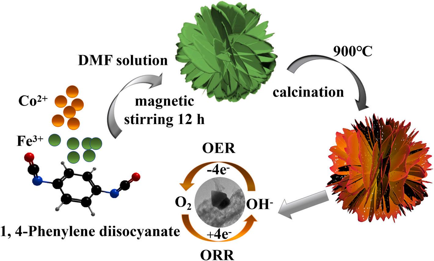
N, N-Dimethylformamide (AR, 99.5 %) and Fe(NO3)3 9H2O (AR, 98.5 %) were purchased from Shanghai Macklin Industrial Corporation, China. 1, 4-Phenylene diisocyanate (AR, 98 %) and Co(NO3)2 6H2O (AR, 99.99 %) were provided by Shanghai Aladdin, China. Commercial 20 % Pt/C was obtained from Johnson Matthey.
2.2. Synthesis of CoFe-CoFe2O4@NCs electrocatalysts
Typically, 1.601 g of 1, 4-Phenylene diisocyanate was dissolved in 100 mL of N, N-Dimethylformamide (DMF) and stirred for 12 h as solution A. 1.164 g Co(NO3)2⋅6H2O and 2.424 g Fe(NO3)3⋅9H2O (the mole ratio of Co(NO3)2 6H2O and Fe(NO3)3 9H2O was 4:6) were added to 100 mL of DMF and stirred until completely dissolved to form solution B. Solution B was slowly added into solution A and stirred for 12 h. The precipitate was washed by ethanol and centrifuged for several times. Finally, the products were dried at 60 ◦ C for 12 h in an oven. The precusor was heated at 900 ◦ C for 2 h at a rate of 5 ◦ C min 1 under Ar atmosphere to obtain the electrocatalyst. This electrocatalyst was marked as CoFe-CoFe2O4@NCs-4, where 4 represents the mole ratio of Co (NO3)2 6H2O and Fe(NO3)3 9H2O is 4:6. Other mole ratios of 1:9, 2:8, 3:7, 5:5 and 6:4 were also synthesized via a similar procedure. These samples are denoted as CoFe-CoFe2O4@NCs-1, CoFe-CoFe2O4@NCs-2, CoFe-CoFe2O4@NCs-3, CoFe-CoFe2O4@NCs-5 and CoFeCoFe2O4@NCs-6, respectively.
2.3. Characterizations
X-ray diffraction (XRD) measurements were performed on Rigaku Miniflex600. Scanning electron microscopy (SEM) measurements were carried out on SU-70. Transmission electron microscopy (TEM) images were collected on JEOL-F200 and HITACHI-HT7700. X-ray photoelectron spectroscopy (XPS) measurements were measured by using Thermo Scientific K-Alpha Nexsa. Raman spectra were obtained on RENIDHAW invia Raman Microscope. The nitrogen adsorption/desorption experiments were performed on Micromeritics ASAP 2020 instrument. The surface structure and roughness information were captured on Bruker Dimension ICON atomic force microscope (AFM).
2.4. Electrochemical measurements
Electrochemical experiments were conducted on a VMP-300 potentiostat with a standard three-electrode system. The Hg/HgO electrode was used as the reference electrode for OER and ORR. A platinum plate and platinum wire were used as counter electrodes for OER and ORR, respectively. To prepare the working electrode, 2 mg catalysts were dispersed in a suspension of ethanol (0.32 mL) and Nafion (5 wt%, 0.02 mL) under sonication for 30 min to form a homogeneous catalyst ink. Subsequently, the catalyst ink (0.012 mL) was pipetted onto the glassy carbon electrode (0.237 cm2) with a load of 0.298 mg cm 2 for ORR and the glassy carbon electrode (0.196 cm2) with a load of 0.360 mg cm 2 for OER, respectively. All the measurements were carried out at room temperature. In ORR test, linear sweeping voltammetry (LSV) curves without IR correction were performed in O2- and N2- saturated 0.1 M KOH solution with the scan speed of 10 mV s 1 under 400 to 2025 rpm. The cyclic voltammetry (CV) was tested in O2- and N2- saturated 0.1 M KOH solution with a scan speed of 25 mV s 1 The rotating ring-disk electrode (RRDE) measurements were performed to calculate H2O2 yield and electron transfer number (n) for ORR. All the measured potentials were referred to RHE using the following Nernst equation:
JournalofEnergyStorage84(2024)110815 2
J. Zou et al.
Electrode kinetic data were analyzed according to the well-known Koutecky-Levich (K-L) equation: 1
B = 0 2nF CO (DO )2/3 ν 1/6
Where j is the measured current, jL and jK is the diffusion limiting current and kinetic current density, respectively, ω is the RRDE rotation speed in rpm, F is the Faraday constant (96,485C mol 1), CO is the bulk concentration of oxygen (1.2 × 10 6 mol cm 1), DO is the diffusion coefficient of oxygen in 0.1 M KOH (1.9 × 10 5 cm2 s 1), v is the kinetic viscosity (0.01 cm2 s 1), n is the electron transfer number in ORR.
The hydrogen peroxide yield (H2O2%) and the number of electrons transferred (n) were calculated using the equation as follows:
H2 O2 (%) = 200 × Ir /N Ir /N + Id (4)
n
Where Id is the disk current, Ir is the ring current, and N (N = 0.38) is the current collection efficiency.
In OER test, LSV curves with 95 % IR correction were performed in O2- saturated 1 M KOH solution with the scan speed of 5 mV s 1 The cyclic voltammetry (CV) was tested in O2- saturated 1 M KOH solution with different scan rates from 20 to 100 mV s 1 Electrochemical impedance spectroscopy (EIS) measurements were carried out on a VMP-300 electrochemical workstation at 1.4 V vs. RHE for OER with an amplitude of 10 mV.
2.5. Zn-air battery tests
The rechargeable Zn-air batteries were assembled by using a zinc plate as an anode. The length, width, and thickness for the customized Zn plate anode were 9 cm, 3 cm, and 0.5 mm, respectively. The prepared catalyst ink was attached to hydrophobic carbon paper (1 cm2) to form the air electrode and 6.0 M KOH aqueous solution with 0.2 M Zn(Ac)2 as an electrolyte, and carbon paper loaded by catalysts (1 mg cm 2). The cycle test was characterized by galvanostatic charge/discharge at 10 mA cm 2 for 10 min for each pulse.
2.6. DFT calculation
The first principle calculations are performed to reveal the mechanism by using the Vienna ab initio simulation package [35,36]. The program has the projected enhancement wave pseudopotential [37]and the generalized gradient approximation of Perdew, Burke, and Enzzerhof (PBE) exchange-correlation functional [38], which is used to optimize the structure and obtain the free energy of all structures. The cutoff energy of the plane waves basis set is 500 eV, and a Monkhorst-Pack mesh of 3 × 3 × 1 is used in K-sampling in the adsorption energy calculation. The electronic self-consistent iteration is set to 10 5 eV, and the positions of all of the atoms are fully relaxed until the residual force on each atom is below 0.02 eV ◦ A 1 . 15◦ A of vacuum layer along the zdirection is applied to avoid periodic interactions.
3. Results and discussion
The fabrication procedure of the CoFe-CoFe2O4@NCs-x nanosheets electrocatalyst was illustrated in Fig. 1. 1, 4-Phenylene diisocyanate was selected as the raw material for construction of two-dimensional materials with unique benzene ring structural features because of its two functional groups in opposition. In the first step, 1, 4-Phenylene diisocyanate molecules coordinated with Co2+ and Fe3+ ions to form 2D nanosheet structural precursors with CoFe and nitrogen-doped nanosheet (CoFe-NDNP), which was proved by the SEM image. Subsequently, CoFe-NDNP precursors were annealed at 900 ◦ C from room temperature and held for 2 h under Ar atmosphere. Finally, the CoFe-CoFe2O4@NCsx nanosheet was obtained successfully.
To evaluate the physical properties of various samples, the XRD spectra were shown in Fig. 2a, CoFe-CoFe2O4@NCs-x exhibited distinct characteristic peaks. The broad diffraction peaks at 26.1◦ and 43.6◦ were assigned to (002) and (100) planes of graphitic carbon. The peaks at 18.2◦ , 30.1◦ , 35.5◦ , 43.5◦ , 57.2◦ and 62.7◦ belong to (111), (220), (311), (400), (511) and (440) planes of CoFe2O4 (PDF#03-0864), respectively. The peaks at around 35.5◦ and 43.9◦ can be assigned to (222) and (330) planes of Co0.72Fe0.28 alloy (PDF#51-0740), respectively. Another peak of 44.9◦ can be reasonably ascribed to the (110) plane of CoFe alloy (PDF#49-1568). The XRD results implied that Co and Fe species existed in carbon materials with the crystalline structure of CoFe alloy and CoFe2O4 In addition, due to the high content of amorphous carbon in the catalyst, the intensity of the characteristic peak for amorphous carbon in the figure was much higher than that CoFe alloy and CoFe2O4. The variation situation of phases for CoFe alloy and CoFe2O4 as the ratio
JournalofEnergyStorage84(2024)110815 3
(RHE ) = E(Hg/HgO) + 0 098 + 0 059 × pH (1)
E
j = 1 jL + 1 jK = 1 Bω1/2 + 1 jK (2)
(3)
4
Id Ir /N + Id (5)
=
×
J. Zou et al.
Fig. 1. Schematic illustration of the formation process of CoFe-CoFe2O4@NCs-x catalysts.

of Co and Fe changed was summarized in the Fig. S1. This result was collected according to the intensities of the main peaks for CoFe alloy and CoFe2O4 signals. It was obviously that the contents of CoFe alloy increased and the contents of CoFe2O4 decreased as the ratio of Fe/Co increased.
Fig. 2b plotted the Raman spectra of CoFe-CoFe2O4@NCs, where five typical peaks at 1180 cm 1 , 1350 cm 1 , 1483 cm 1 , 1590 cm 1 and 2850 cm 1 were assigned to the I-band, D- band, D"-band, Gband and G’-band of carbon, respectively [39–41]. It was well known that D-band was associated with defects and disorder structures of carbon materials, while G-band was associated with graphitic structures. Iband formation resulted from disordered graphitic lattice and ionic impurities or heteroatoms, such as nitrogen-doing in carbons. The D"band was ascribed to typical amorphous carbon. The G’-band was attributed to structural defects caused by nitrogen atom doping in carbon materials. The ratio of their intensities (ID/IG) can be used to determine the degree of disorder and graphitic in the structure of the materials [31]. High topological defect and disorder degree were favorable to the exposure of active sites. At the same time, the high degree of graphitic was beneficial for improving electrical conductivity, which can accelerate the electron transfer during electrocatalytic reaction [28]. Based on the Raman analysis in Fig. 2b, the ID/IG values of the catalysts were 1.48, 1.43, 1.45, 1.47, 1.59 and 1.54, corresponding to CoFe-CoFe2O4@NCs-1, CoFe-CoFe2O4@NCs-2, CoFe-CoFe2O4@NCs-3, CoFe-CoFe2O4@NCs-4, CoFe-CoFe2O4@NCs-5 and CoFe-
CoFe2O4@NCs-6, respectively. The results showed that the catalyst had high topological defects and a disordered structure, which ensured the complete exposure of electrocatalytic active sites. CoFe-CoFe2O4@NCs5 and CoFe-CoFe2O4@NCs-6 showed higher ID/IG value, it was because the concentration of iron played a positive influence in the degree of graphitization [42]. Furthermore, compared with CoFe-CoFe2O4@NCs catalysts, the ID/IG value of NCs catalyst (Fig. S2) was only 1.30, which proved that the defect degree of the catalysts increased significantly after the introduction of metal species [43,44]. It was because the emerging of oxygen groups from the introduction of metal species can decrease the average size of sp2 hybridized carbon atom domains, thereby, the chemical structure of carbon was disordered and disordered vibration increased. The N2 adsorption/desorption isothermal curves of various CoFe-CoFe2O4@NCs-x electrocatalysts were recorded to distinguish the specific surface areas and pore size distribution, as shown in Fig. 2c-d. When the relative pressure approaches 0, the mass adsorption value of the catalyst increases rapidly, indicating large amounts of micropores in the catalyst. A typical Type-IV profile at a relative pressure of 0.7 showed a large number of mesoporous and macropores in the catalyst. Meanwhile, the pore size distribution curve showed that all the catalysts had hierarchical carbon structures. As shown in Fig. 2d and Fig. S3, the pores size was mainly 20 nm for CoFe2O4@NCs-x. The total pore volumes and the specific surface areas of CoFe-CoFe2O4@NCs-4 were 1.37cm3 g 1 and 545.9 m3 g-1, respectively. The hierarchical
JournalofEnergyStorage84(2024)110815 4
J. Zou et al.
Fig. 2. a) XRD patterns, b) Raman spectra, c) N2 adsorption/desorption isotherms and d) pore size distribution of CoFe-CoFe2O4@NCs-1, CoFe-CoFe2O4@NCs-2, CoFe-CoFe2O4@NCs-3, CoFe-CoFe2O4@NCs-4, CoFe-CoFe2O4@NCs-5 and CoFe-CoFe2O4@NCs-6.
carbon structure with high specific surface area and high pore volume was beneficial for i) effective exposure of the active sites; ii) adequate wetting of the electrode/electrolyte interface; iii) effective removal of gas during the OER process; iv) efficient entry of gas during the ORR process.
Scanning electron microscopy (SEM) and transmission electron microscopy (TEM) were used to observe the microstructure of the synthesized samples. Fig. 3a, Fig. S4 and Fig. S5a-S9a indicated that the CoFe-CoFe2O4@NCs-x catalysts still maintained a complete 2D nanosheet structure of CoFe-NDNP with a large number of defects and pore structures. The rapid pyrolysis and gradual decomposition under Ar atmosphere mitigated the deformation of CoFe-NDNP, and the 2D nanosheet structure can be successfully maintained as needed. The results were consistent with the Raman spectrum and nitrogen adsorption/ desorption curves. The thickness of the 2D carbon nanosheets for CoFeCoFe2O4@NCs-4 was around 5.9 nm, as shown in the AFM image (Fig. S10). The particle sizes of CoFe-CoFe2O4@NCs-x catalysts were 650 nm - 680 nm in average as shown in the Fig. S11. Furthermore, in Fig. 3b and Fig. S4b-S8b, the metal nanoparticles were uniformly distributed on the nanosheet. The high-resolution transmission electron microscopy (HRTEM) images (Fig. 3c, Fig. S5c-S9c) revealed that the nanoparticles consisted of two parts, and a distinct heterogeneous interface can be observed. Meanwhile, the images of the energydispersive X-ray spectroscopy (EDS) elemental mappings (Fig. 3d, Fig. S5d-S9d) indicated that Co, Fe and O elements were evenly distributed in the metal nanoparticles, and C and N elements were uniformly distributed in the carbon nanosheet. These results evidenced
the construction of the heterogeneous interfacial structure and the coexistence of CoFe and CoFe2O4.
The corresponding line scanning and the HRTEM images also revealed the interior structures and element distributions of CoFeCoFe2O4@NCs-x catalysts. As shown in Fig. 3f and Fig. S5f-S9f, the element content of nanoparticles changed obviously at the interface. Moreover, the HRTEM images (Fig. S5g) indicated that the lattice fringes of the CoFe-CoFe2O4@NCs-1 were consistent with the (111) plane of CoFe2O4 with an interspacing of 0.494 nm and the CoFe alloy with an interspacing of 0.208 nm. The interspacing of the (311) plane of CoFe2O4 (Fig. S6g, S7g, 3 g, S8g and S9g) were 0.261 nm, 0.258 nm, 0.255 nm, 0.258 nm and 0.258 nm, corresponding to CoFeCoFe2O4@NCs-2, CoFe-CoFe2O4@NCs-3, CoFe-CoFe2O4@NCs-4, CoFeCoFe2O4@NCs-5 and CoFe-CoFe2O4@NCs-6 catalysts, respectively, which further confirmed the construction of the heterogeneous interfacial structure of CoFe-CoFe2O4@NCs-x catalysts. The formation of heterogeneous interfaces resulted in a strain on the (330) plane of CoFe alloy, the (111) and (331) planes of CoFe2O4, leading to a slight stretching in the lattice. At the same time, the rearrangement of electrons at the heterogeneous interface created a fast electron transport channel at the atomic level, which could promote the electrocatalytic reaction.
X-ray photoelectron spectroscopy (XPS) were applied to further investigate the surface electronic state and chemical composition of electrocatalysts. As shown in Fig. 4a, the XPS survey spectra revealed the existence of C, N, Co, Fe and O elements in all CoFe-CoFe2O4@NCs electrocatalysts. As displayed in Fig. S12, the spectrum of C1s can be

JournalofEnergyStorage84(2024)110815 5
J. Zou et al.
Fig. 3. (a) SEM, (b) TEM, (c) HRTEM, (d) EDS mapping images, (e) STEM, (f) Line scan, and (g) enlarged view of HRTEM images for CoFe-CoFe2O4@NCs-4.

Fig. 4. a) Survey XPS spectrum of CoFe-CoFe2O4@NCs-1, CoFe-CoFe2O4@NCs-2, CoFe-CoFe2O4@NCs-3, CoFe-CoFe2O4@NCs-4, CoFe-CoFe2O4@NCs-5 and CoFeCoFe2O4@NCs-6. b-e) High-resolution XPS spectra of N 1s, Co 2p, Fe 2p and O 1s, respectively. f) EPR spectra of CoFe-CoFe2O4@NCs-x catalysts.
divided into five characteristic peaks centered at 284.6 eV, 285.9 eV, 286.9 eV, 288.4 eV and 290.8 eV, corresponding to the configuration C–C, C-N/C-O, C=N/C=O, O-C=O and π-π*, respectively, which illustrated that the N atoms had been doped into carbon frameworks. XPS peaks for N 1 s (Fig. 4b) were centered at 397.9 eV, 398.8 eV, 399.8 eV, 400.6 eV and 403.1 eV, corresponding to pyridinic N, metal N, pyrrolic N, graphitic N, and oxidized N, respectively [45–47]. The graphitic N were dominant in catalysts, which benefited ORR process by improving electrical conductivity of the carbon matrix effectively. The contents of pyridinic N and pyrrolic N were moderate, pyrrolic N occupied around 15 % and pyridinic N occupied 7 % in average (Fig. S13). Pyridinic N species can also contribute to electrochemcial performance improvement since they were regarded as important active sites resulted from their numerous defects [48,49]. The high-resolution Co 2p spectrum (Fig. 4c) revealed the surface composition and chemical state of CoFeCoFe2O4@NCs. In the Co 2p spectrum of CoFe-CoFe2O4@NCs, the peaks at 779.5 eV and 794.4 eV correspond to the 2p3/2 and 2p1/2 peaks of Co0 species, while the peaks at 780.6 eV and 796.3 eV can be assigned to the 2p3/2 and 2p1/2 peaks of Co2+ species, respectively. The peaks at 782.7 eV and 797.6 eV were attributed to the 2p3/2 and 2p1/2 of Co3+ species, respectively. In addition, the corresponding satellite peaks of Co 2p were centered at 714.4 eV and 732.5 eV [50,51]. In the Fe 2p spectrum (Fig. 4d), the Fe 2p3/2 peaks located at 708.5 eV, 710.4 eV and 712.3 eV represented Fe 0 , Fe 2+ and Fe 3+ , respectively. The Fe 2p1/2 peaks centered at 720.7 eV, 723.0 eV and 725.6 eV corresponded to Fe 0 , Fe 2+ and Fe 3+ , respectively. Satellite peaks of Fe 2p were located at 718.8 eV and 729.9 eV [52]. It had been proved that the transformation of Fe2+/ Fe3+ and Co2+/Co3+ pairs in the CoFe2O4 species were responsible for the catalytic performance improvement resulting from the valency transformation. The Co2+/Co3+ and Fe2+/Fe3+ atom ratios on the surface of CoFe-CoFe2O4@NCs-x catalysts were calculated by comparing the fitted curves covered areas [19]. According to Fig. S14, the atomic ratios of Co2+/Co3+ and Fe2+/Fe3+ in the catalyst fluctuated gradually with the change of Co and Fe ratios. The atomic ratios of Co2+/Co3+ and Fe2+/Fe3+ for the CoFe-CoFe2O4@NCs-4 (1.20, 1.16) catalyst were higher than those of CoFe-CoFe2O4@NCs-1 (0.74, 0.79), CoFeCoFe2O4@NCs-2 (0.90, 0.91), CoFe-CoFe2O4@NCs-3 (0.95, 1.02), CoFeCoFe2O4@NCs-5 (0.89, 0.92) and CoFe-CoFe2O4@NCs-6 (0.77, 0.86), indicating the considerable Co2+ and Fe2+ species on the surface of the
CoFe-CoFe2O4@NCs-4 catalysts. During the transformation of Co3+ and Fe3+ species to Co2+ and Fe2+ species, oxygen atoms in the lattice of CoFe2O4 were separated and promoted the formation of oxygen vacancies. Therefore, the contents of oxygen vacancies varied as the change of Co and Fe ratios. In addition, the precipitation amount of CoFe alloy in the catalysts compared with CoFe2O4 was shown in Fig. S15, which were calculated by comparing the fitted curves covered areas for Fe0 and Co0 peaks. The amount increased with the increase of Co:Fe ratio. Furthermore, the ICP results for CoFe-CoFe2O4@NCs-x catalysts were shown in Table S1, the contents of Co and Fe in samples shifted as the change of added ratio for Co/Fe during sample preparation stage. The content of CoFe alloy increased as the increase of the amount for Fe. The heterogeneous interface between CoFe alloy and CoFe2O4 also changed, which was favorable for regulating oxygen vacancy content in the catalyst. This phenomenon was also consistent with the TEM results. Meanwhile, the formation of oxygen vacancies can also be demonstrated by their high-resolution O 1s spectra. In Fig. 4e, the O 1s spectrum can be fitted into three peaks, located at 530.5 eV, 531.9 eV and 533.1 eV, corresponding to Metal-O, Ovac and -OH, respectively [53–55]. The contents of metal-O were collected and shown in Fig. S16, they reached 23.4 % when x = 3. The variation of the contents for metal-O associated with the ratio of Co2+/Co3+ and Fe2+/Fe3+ atoms as well as CoFe2O4 alloy content in CoFe-CoFe2O4@NCs-x catalysts. Comparing the areas covered by the fitted curves, CoFe-CoFe2O4@NCs-4 catalyst had the highest density of Ovac (50.1 %), as shown in Fig. S17. It was generally recognized that surface oxygen vacancy significantly affects the physical and chemical properties of electrocatalytic materials [19,56]. The electron paramagnetic resonance (EPR) was also used to evaluate the formation of oxygen vacancy species, as shown in Fig. 4f. The g factors for CoFe-CoFe2O4@NCs-x catalysts were calculated as 2.003, which can be attributed as oxygen vacancies [19]. The peak signal intensity increased and reached the maximum value when x was 4 (CoFeCoFe2O4@NCs-4), indicating that CoFe-CoFe2O4@NCs-4 exhibited the most oxygen vacancies in all prepared catalysts. The generation of oxygen vacancy can effectively regulate the electron structure of catalysts surface, enhance electron enrichment and change electron charge transfer ability [24,57]. Moreover, oxygen vacancy can promote the adsorption of water molecules on the catalyst surface. These results were highly beneficial to the improvement of electrocatalytic activity.
JournalofEnergyStorage84(2024)110815 6
J. Zou et al.
The three-electrode system tested the catalytic activity of CoFeCoFe2O4@NCs-x catalysts toward ORR and OER in an alkaline electrolyte to evaluate the effect of heterogeneous interfacial structure.
Fig. S18a showed the CV curves of CoFe-CoFe2O4@NCs-x and 20 wt% Pt/C catalyst at 25 mv s 1 in 0.1 m KOH solution saturated with N2 and O2 The obvious reduction peak in the O2-saturated system demonstrated the oxygen reduction on CoFe-CoFe2O4@NCs-x. As shown in Fig. S18b, the CV curves exhibited the reduction peaks of 0.67 V, 0.78 V, 0.78 V, 0.79 V, 0.78 V, 0.78 V, 0.78 V and 0.86 V for NCs, CoFeCoFe2O4@NCs-1, CoFe-CoFe2O4@NCs-2, CoFe-CoFe2O4@NCs-3, CoFeCoFe2O4@NCs-4, CoFe-CoFe2O4@NCs-5, CoFe-CoFe2O4@NCs-6 and 20 wt% Pt/C, respectively. Further evidence were concluded by the linear sweep voltammetry (LSV) tests, and the ORR activity was evaluated by the half-wave potential (E1/2). The LSV cures of catalysts were shown in Fig. 5a, and the values for E1/2 were presented in Fig. 5b. Their E1/2 for ORR were 0.71 V, 0.84 V, 0.82 V, 0.84 V, 0.83 V, 0.81 V, 0.81 V and 0.82 V, corresponding to NCs, CoFe-CoFe2O4@NCs-1, CoFeCoFe2O4@NCs-2, CoFe-CoFe2O4@NCs-3, CoFe-CoFe2O4@NCs-4, CoFeCoFe2O4@NCs-5, CoFe-CoFe2O4@NCs-6 and 20 wt% Pt/C, respectively. The ORR activity of the CoFe-CoFe2O4@NCs-x catalysts was comparable to or even higher than 20 wt% Pt/C. In addition, the ORR catalytic performance of CoFe-CoFe2O4@NCs-x catalyst was superior to that of the NCs catalyst. To further demonstrate the ORR electrocatalytic activity, the kinetic current density derived from Tafel slope was displayed in Fig. 5c. The Tafel slope of the CoFe-CoFe2O4@NCs-1 (78.94 mV dec 1) electrocatalyst was the smallest than those of NCs (146.17 mV dec 1), CoFe-CoFe2O4@NCs-2 (94.99 mV dec 1), CoFe-CoFe2O4@NCs3 (81.28 mV dec 1), CoFe-CoFe2O4@NCs-4 (89.17 mV dec 1), CoFeCoFe2O4@NCs-5 (97.12 mV dec 1), CoFe-CoFe2O4@NCs-6 (102.27 mV dec 1) and 20 wt% Pt/C (81.36 mV dec 1), demonstrating a better electron transfer efficiency and high kinetic activity for ORR. The LSV measurements at different rotation rates and the corresponding Koutecky–Levich plots were implemented to research the ORR kinetics mechanism. As shown in Fig. 5d and Fig. S19, the current density of CoFe-CoFe2O4@NCs-x increased gradually with the rise of electrode rotation rates, suggesting that the ORR on the CoFe-CoFe2O4@NCs-x
catalyst was a kinetically-controlled process [58]. In addition, the Koutecky–Levich curves (inset of Fig. 5d and Fig. S19) displayed a good linear relationship, demonstrating that the ORR process on the CoFeCoFe2O4@NCs-x catalyst followed the first-order reaction kinetics toward oxygen. The average electron-transfer numbers of CoFeCoFe2O4@NCs-1, 2, 3, 4, 5 and 6, 20 wt% Pt/C and NCs were 3.81, 3.64, 3.78, 3.99, 3.98, 3.99, 3.95 and 3.64, respectively. It evidenced that all materials underwent a predominant four-electron transfer process in ORR. Furthermore, to investigate the electron-transfer number and the yield of H2O2 in ORR process, the rotating ring-disk electrode (RRDE) measurements were performed on NCs, CoFe-CoFe2O4@NCs-x and 20 wt% Pt/C. As shown in Fig. 5e, the ring currents of NCs were almost negligible compared with the disk currents of the CoFe-CoFe2O4@NCs-x catalysts. The H2O2 yields of the CoFe-CoFe2O4@NCs-x catalysts (1.09–13.72 %) in the ORR process were also negligible, and the electron transfer numbers were 3.78–3.95. At the same time, the ring current of the NCs catalyst was relatively large (the H2O2 yield of 26.39–38.42 % and the electron transfer number of 3.25–3.47). The results further confirmed that the CoFe-CoFe2O4@NCs-x catalysts for ORR were the predominant direct 4-electron transport pathways, suggesting good ORR catalytic efficiency. The durability of the CoFe-CoFe2O4@NCs-4 and 20 wt% Pt/C catalysts were evaluated at 0.6 V with the rotation speed of 200 rpm in O2-saturated 0.1 M KOH solution. The CoFe-CoFe2O4@NCs4 catalyst was selected to evaluate the durability compared with the 20 wt% Pt/C catalyst since it showed better electrochemical performance of both OER and ORR than the CoFe-CoFe2O4@NCs-1 catalyst. As shown in Fig. 5f, the CoFe-CoFe2O4@NCs-4 catalyst reserved 95 % initial current after continuously working for 10 h, while the 20 wt% Pt/C catalyst only retained 92.6 % of initial current density. It indicated that the durability of the CoFe-CoFe2O4@NCs-4 catalyst outperformed 20 wt% Pt/C catalyst. At the same time, the methanol resistance of CoFe-CoFe2O4@NCs-4 catalyst (inset of Fig. 5f) was much better than that of 20 wt% Pt/C catalyst. When methanol was added, the current of 20 wt% Pt/C catalyst decreased rapidly, while that of CoFe-CoFe2O4@NCs-4 catalyst hardly changed. The above results illustrated that excellent ORR catalytic activity could benefit from i) 2D nitrogen-doped carbon nanosheets

Fig. 5. a) LSV polarization curves at 1600 rpm and b) the corresponding half-wave potential of the samples. c) The corresponding Tafel plots are derived from ORR LSV curves at 1600 rpm. d) Rotation rate dependent ORR polarization plots of CoFe-CoFe2O4@NCs-4. The inset shows the related Koutecky–Levich (K–L) curves at various potentials. e) Peroxide yields and electron transfer number derived from the 1600 rpm RRDE curves of the samples. f) Chronoamperometric measurements for CoFe-CoFe2O4@NCs-4 and 20 wt% Pt/C with a rotation rate of 1600 rpm at 0.6 V for 10 h (Inset: The testing of anti-methanol ability).
JournalofEnergyStorage84(2024)110815 7
J. Zou et al.
structure; ii) high porosity and high specific surface area ensure full exposure of the active site; iii) the synergetic effect between pyridinic-N, graphitic-N, CoFe alloy and CoFe2O4 active sites.
In order to evaluate the OER performance of catalysts, linear sweep voltammetry (Fig. 6a) was used to measure the catalytic performance of catalysts in an O2-saturated 1 M KOH solution. The overpotential assessed the OER activity (Fig. 6b) of the catalysts at 10 mA cm 2 (Ej=10). The potentials were 1.72 V, 1.63 V, 1.62 V, 1.59 V, 1.55 V, 1.57 V, 1.61 V and 1.51 V, corresponding to NCs, CoFe-CoFe2O4@NCs-1, CoFe-CoFe2O4@NCs-2, CoFe-CoFe2O4@NCs-3, CoFe-CoFe2O4@NCs-4, CoFe-CoFe2O4@NCs-5, CoFe-CoFe2O4@NCs-6 and RuO2 catalyst, respectively. The CoFe-CoFe2O4@NCs-4 electrocatalyst showed the optimal OER catalytic activity among CoFe-CoFe2O4@NCs-x catalyst. The trend of OER performance for CoFe-CoFe2O4@NCs was consistent with that of oxygen vacancies content, and CoFe-CoFe2O4@NCs-4, with highest oxygen vacancies content (%), had the lowest overpotential. Moreover, compared with NCs catalyst, the OER catalytic activity of CoFe-CoFe2O4@NCs-x catalysts were improved after the introduction of transition-metal nanoparticles. As shown in the Fig. S20, Faradaic efficiency of CoFe-CoFe2O4@NCs-4 catalyst for OER was calculated as 93.1 %, which based on the quotient of the ring current divided by the disk current and the collection efficiency [59]. Furthermore, the Tafel slope evaluates the reaction kinetic process in OER process. As shown in Fig. 6c, the Tafel slopes were 222.1 mV dec 1 , 197.4 mV dec 1 , 178.8 mV dec 1 , 167.59 mV dec 1 , 126.6 mV dec 1 , 152.6 mV dec 1 , 172.45 mV dec 1 , and 70.5 mV dec 1 , corresponding to NCs, CoFeCoFe2O4@NCs-1, CoFe-CoFe2O4@NCs-2, CoFe-CoFe2O4@NCs-3, CoFeCoFe2O4@NCs-4, CoFe-CoFe2O4@NCs-5, CoFe-CoFe2O4@NCs-6 and RuO2, respectively. The CoFe-CoFe2O4@NCs-x catalyst showed a relatively small Tafel slope, representing a favorable OER kinetic process and higher activity. In order to evaluate the actual catalytic activity of the prepared samples, the surface area involved in the catalytic reaction was approximated by the electrochemical double-layer capacitor (Cdl). Cyclic voltammetry was used to measure the double-layer capacitance
current in the non-Faraday region at different sweep speeds (Fig. 6d and Fig. S21), the Cdl value of catalysts were obtained by linear fitting. As shown in Fig. 6e, the Cdl value of catalysts were 29.86 mF cm 1 , 97.76 mF cm 1 , 99.79 mF cm 1 , 133.15 mF cm 1 , 101.20 mF cm 1 and 90.69 mF cm 1 , corresponding to CoFe-CoFe2O4@NCs-1, CoFeCoFe2O4@NCs-2, CoFe-CoFe2O4@NCs-3, CoFe-CoFe2O4@NCs-4, CoFeCoFe2O4@NCs-5 and CoFe-CoFe2O4@NCs-6, respectively. The CoFeCoFe2O4@NCs-4 catalyst had the maximum Cdl value, indicating the largest actual area of catalytic reaction. Besides, the increase trend of Cdl value was consistent with the ratio change for Co2+/Co3+ and Fe2+/Fe3+ atoms, and oxygen vacancy content alteration in CoFe-CoFe2O4@NCs-x catalysts. It demonstrated that the oxygen vacancy content resulting from element ratio also could affect the actual content of active site. The resistance of catalysts was important for electron transportation in OER. To reveal the charge transfer resistance (Rct) and solution resistance (Rs) between the catalysts, electrochemical impedance spectra (EIS) of those electrodes were recorded in Fig. 6f. The semicircle corresponded to an Rct between the surface of the electrocatalyst and electrolyte, and the Rct for catalysts were 388.9, 29.81, 25.81, 21.44, 11.61, 15.45 and 13.47 Ω, corresponding to NCs, CoFe-CoFe2O4@NCs-1, CoFe-CoFe2O4@NCs-2, CoFe-CoFe2O4@NCs-3, CoFe-CoFe2O4@NCs-4, CoFe-CoFe2O4@NCs-5 and CoFe-CoFe2O4@NCs-6, respectively. Besides, the Rs for these electrodes were displayed in Table S2. These results strongly suggested that the construction of heterogeneous interface played a significant role in decreasing charge transfer resistance. Moreover, oxygen vacancy can increase the adsorption capacity of the catalyst surface for water molecules, which endowed the superior OER catalytic activity of the CoFeCoFe2O4@NCs-4 catalyst. This was consistent with the results of XPS characterization. The stability of CoFe-CoFe2O4@NCs-4 was explored by the LSV measurement before and after a continuous CV test for 1000 cycles at a scan rate of 100 mV s 1 . As shown in Fig. S22, only a slight shift (36.5 mV) was observed in the LSV curve of CoFe-CoFe2O4@NCs-4 after 1000 cycles, clearly confirming the outstanding durability of CoFeCoFe2O4@NCs-4 catalyst during OER. The TEM and XRD results of

Fig. 6. a) LSV polarization curves in O2-saturated 1 M KOH solution and b) the corresponding OER potential at 10 mA cm 2 of the samples. c) The corresponding Tafel plots are derived from their LSV curves. d) CV curves at different scan rates from 20 to 100 mV s 1 e) Double-layer capacitances (Cdl) of the samples. f) EIS Nyquist plots of the samples.
JournalofEnergyStorage84(2024)110815 8
J. Zou et al.
CoFe-CoFe2O4@NCs-4 catalyst after OER stability test were shown in Fig. S23 and S24. The nanoparticles with distinct heterogeneous interface of CoFe alloy and CoFe2O4 nanoparticles still maintained. While the area of CoFe alloy enlarged and that of CoFe2O4 nanoparticles shrank slightly. The XRD spectra also reflected this situation, the intensity of CoFe alloy increased and that of CoFe2O4 nanoparticles decreased relatively. The slight change of the contents for CoFe alloy and CoFe2O4 nanoparticles was the main reason for the slight shift in the LSV curve after stability test. The XPS results of CoFe-CoFe2O4@NCs-4 catalyst after OER stability test were shown in Fig. S25, the fitted curves covered areas for Fe0 and Co0 peaks were smaller than those in the XPS results before OER. It was because that OER process can lead to the oxidation of metallic nanoparticles (Co and Fe) in the surface, partial CoFe alloy was oxidized into Co/Fe hydroxides [60,61].
The ORR and OER bifunctional electrocatalytic activities of catalysts was assessed by the difference of potentials values (ΔE = Ej=10 – E1/2) between the OER potential at 10 mA cm 2 and the ORR potential at halfwave. The overall polarization curves of all catalysts within the ORR and OER potential window was shown in Fig. 7a. As depicted in Fig. 7b, the value of ΔE for NCs, CoFe-CoFe2O4@NCs-1, CoFe-CoFe2O4@NCs-2, CoFe-CoFe2O4@NCs-3, CoFe-CoFe2O4@NCs-4, CoFe-CoFe2O4@NCs-5,
CoFe-CoFe2O4@NCs-6 and Pt/C + RuO2 catalyst were 1.01, 0.79, 0.80, 0.75, 0.72, 0.76, 0.80 and 0.69 V, respectively. The CoFeCoFe2O4@NCs-4 electrocatalyst exhibited the smallest ΔE of 0.72 V among CoFe-CoFe2O4@NCs-x catalysts, and it demonstrated that its excellent bifunctional electrocatalytic activities were comparable to that of Pt/C + RuO2 (ΔE = 0.69 V). To the best of our knowledge, the value of ΔE was also superior to those recently reported the ORR and OER bifunctional catalysts (Table S3). To evaluate the potential of practical application for the CoFe-CoFe2O4@NCs-4 bifunctional electrocatalyst, Zn-air batteries were assembled by a carbon paper coated with the CoFeCoFe2O4@NCs-4 catalyst as the air electrode and a zinc plate as the anode in 6.0 M KOH + 0.2 M Zn(Ac)2 electrolyte. As shown in Fig. S26 the CoFe2O4@NCs-4 catalyst assembled Zn-air battery delivered an open circuit voltage of 1.551 V, higher than that of Pt/C + RuO2 catalyst (open circuit voltage of 1.423 V). Moreover, the assembled battery delivered a continuously high and stable open circuit voltage for 1500 s (Fig. S27), indicating excellent catalytic durability for oxygen reduction. The corresponding discharge-charge curves of the Zn-air battery were exhibited in Fig. 7c. The voltage gap of CoFe2O4@NCs-4-based battery was smaller than that of Pt/C + RuO2 catalyst-based battery, suggesting the outstanding rechargeable capability of CoFe2O4@NCs-4-based

Fig. 7. (a) The overall polarization curves of all catalysts within the ORR and OER potential window; (b) The ΔE (Ej 10-E1/2) of all catalysts. (c) Discharge/charge polarization curves. (d) Discharge polarization curves and the corresponding power density plots of Zn-air batteries with CoFe-CoFe2O4@NCs-4 and Pt/C + RuO2 catalysts. (e) Galvanostatic discharge curves of Zn-air batteries with CoFe-CoFe2O4@NCs-4 and Pt/C + RuO2 catalysts at 10 mA cm 2 (f) Rate performance of CoFeCoFe2O4@NCs-4 and Pt/C + RuO2 catalysts at a current density of 10, 20, 30, 40, 50, and 10 mA cm 2 , respectively. (g) Galvanostatic discharge-charge cycling curves at 10 mA cm 2
JournalofEnergyStorage84(2024)110815 9
J. Zou et al.
battery. The corresponding polarization curves and power density curves were plotted in Fig. 7d. The CoFe2O4@NCs-4-based battery presented an outstanding power density of 106.32 mW cm 2 , much higher than that of commercial Pt/C + RuO2 (62.64 mW cm 2) catalyst. As shown in Fig. 7e, the CoFe2O4@NCs-4-based battery delivered a stable discharge voltage at 10 mA cm 2 with a specific capacity was 785 mA h g 1 , which was superior to that of Pt/C + RuO2 catalyst-based battery (702 mA h g 1). The galvanostatic discharge test results (Fig. 7f) showed that the discharge voltages of CoFe2O4@NCs-4-based battery were higher than those of Pt/C + RuO2 catalyst-based battery from 10 mA cm 2 to 50 mA cm 2 , which represented the superior rate performance. When the current density returned to 10 mA cm 2 , the capacity value of the CoFe2O4@NCs-4-based battery recovered back (from 1.16 V to 1.15 V), while that of Pt/C + RuO2 catalyst-based battery suffered from a capacity fading (from 1.17 V to 1.08 V) during the cycles with an increase of the current densities. Moreover, multiple Znair batteries in series with the CoFe2O4@NCs-4 air-electrodes were assembled into circuits with an open-circuit voltage of 2.91 V (Fig. S28).
A green light-emitting diode (LED, 2.8 V) was lighted up by the multiple Zn-air batteries in series (Fig. S29), confirming the promising potential in practical application. As shown in Fig. 7g, the Pt/C + RuO2-based battery failed quickly with limited cycle stability (139 h, 382 cycles) at the current density of 10 mA cm 2 , while the battery assembled by CoFe2O4@NCs-4 showed an good stability with only 117 % for 500 h (1365 cycles). The outstanding rechargeability and long-term durability may ascribe to the heterogeneous interfacial structure, oxygen vacancy and surface chemical state stability of the electrocatalyst.
DFT calculation reveals the effect of CoFe-CoFe2O4 heterogeneous interfacial structure on ORR and OER activity and the detailed reaction mechanism. The Gibbs free energy and binding energy of CoFe, CoFe2O4 and CoFe-CoFe2O4 were measured and shown in Fig. 8. As shown in Fig. 8a, CoFe2O4 had the highest binding energy of intermediates (*OH, *O, and *OOH), indicating the strongest adsorption capacity and the weakest dissociation capacity. On the other hand, CoFe alloy had the lowest binding energy for intermediates (*OH, *O, and *OOH), indicating the weakest adsorption ability and the strongest dissociation ability. The conjugation of CoFe2O4 and CoFe can balance the adsorption ability and dissociation ability, which is beneficial for oxygen reactions. It also demonstrated that the construction of heterogeneous interfacial structure regulated the adsorption and dissociation ability of intermediates during the OER and ORR reactions [62]. The rate-
determining step was determined by comparing the changes of Gibbs free energy in the four reaction steps. As shown in Fig. 8b and Table S4, the free energies for CoFe, CoFe2O4 and CoFe-CoFe2O4 in the third step (*O to *OOH) all were the highest, indicating that the third step was the rate-determining step. The lowest Gibbs free energy of the ratedetermining step for CoFe-CoFe2O4 evidenced the function of heterogeneous interfacial structure on intermediate adsorption ability enhancement and catalytic capacity improvement. Meanwhile, in the ORR, the rate-determining step for CoFe, CoFe2O4 and CoFe-CoFe2O4 was the last step (*OH + e to OH ). The free energy of the ratedetermining step (U = 1.23 V) for CoFe, CoFe2O4 and CoFe-CoFe2O4 were 1.02 V, 0.85 V and 0.44 V, respectively, and that of CoFe-CoFe2O4 was the lowest. It also demonstrated that the heterogeneous interface between CoFe and CoFe2O4 can modulate the binding energies of the intermediates and optimize the reaction pathways of OER and ORR [19,63]. The D-band centers of CoFe, CoFe2O4 and CoFe-CoFe2O4 were obtained through density of state (DOS) analysis, as shown in Fig. 8d-f. The D-band center of heterogeneous interface was 2.23 eV, while that of CoFe (330) and CoFe2O4 (311) were 2.30 eV and 1.64 eV, respectively. The D-band center of heterogeneous interface was closer to the Fermi level (0 eV) than that of CoFe but further than that of CoFe2O4, and it depicted the moderate adsorption capacity for the intermediate. This result corresponded to those in the free energy diagrams. Furthermore, the total DOS for CoFe-CoFe2O4 was the largest than those of CoFe and CoFe2O4, indicating that the heterogeneous interfacial structure of CoFe and CoFe2O4 contributed to more free electrons and more active sites for the redox reaction. The charge density difference (Fig. 8g) showed that the electron density depletion areas were mainly concentrated around CoFe, while the electron density accumulation areas were concentrated around CoFe2O4. The charge transfer from CoFe to CoFe2O4 regulated the inner electron distribution and balanced the absorption-desorption capability of the CoFe-CoFe2O4 heterogeneous interface during redox reaction. It also verified the existence of the “acceptance-donation” mechanism between CoFe and CoFe2O4, which endowed superior electrochemical performance via enhancement of adsorption energy for O intermediate and catalytic kinetics improvement [64,65]. The basic molecular configuration diagrams for CoFe, CoFe2O4 and CoFe-CoFe2O4 were shown in Fig. S30-S33. The raw data for Gibbs free energies were shown in Table S5.

Fig. 8. (a) The diagram for binding energies of CoFe, CoFe2O4 and CoFe-CoFe2O4 Free-energy diagrams of CoFe, CoFe2O4 and CoFe-CoFe2O4 for (b) OER and (c) ORR at the equilibrium potential (U = 1.23 V). The density of states for (d) CoFe, (e) CoFe2O4 and (f) CoFe-CoFe2O4 (g) The charge density differences of CoFeCoFe2O4 (isosurface value = 0.008e Å 3).
JournalofEnergyStorage84(2024)110815 10
J. Zou et al.
4. Conclusions
In summary, the CoFe-CoFe2O4@NCs-4 catalyst was synthesized by using a facile and efficient approach to construct 2D nitrogen-doped carbon nanosheets as the bifunctional oxygen electrocatalysts with massive oxygen vacancies and heterogeneous interfaces between CoFe alloy and CoFe2O4 nanoparticles. The rational design of the CoFeCoFe2O4@NCs catalysts improved the charge transfer efficiency and the electrocatalytic activity toward ORR and OER. Due to the rich oxygen vacancies, CoFe-CoFe2O4@NCs-4 catalyst exhibited superior electrochemical properties of a low overpotential of 320 mV and a high halfwave potential of 0.83 V. The overall oxygen reactions was only 0.72 V. The excellent OER and ORR bifunctional catalytic performance of CoFe-CoFe2O4@NCs-4 could be attributed to ultrahigh specific surface area (545.9 m2g 1), heterogeneous interfacial structure, the massive oxygen vacancies (50.1 %), and synergistic coupling effects among active species, such as pyridinic-N, graphitic-N, CoFe alloy and CoFe2O4 species. Moreover, the reversible Zn-air battery assembled by CoFeCoFe2O4@NCs-4 catalyst as air cathode presented an outstanding power density of 106.32 mW cm 2 and excellent long-term durability (500 h, 117 %) at the current density of 10 mA cm2 DFT calculations revealed that the formation of heterogeneous interfacial structures could regulate the electronic structure of OER and ORR processes and modulate the energy barriers of intermediates during the OER and ORR. Overall, this work provided a reasonable approach for developing efficient and scalable OER and ORR bifunctional catalysts in rechargeable metal-air batteries.
CRediT authorship contribution statement
Jizhao Zou: Supervision, Funding acquisition. Tao Liang: Resources, Formal analysis. Minggui Peng: Resources. Peng Liu: Resources. Jiaming Wen: Resources. Zhangjian Li: Resources. Yusheng Yan: Resources. Xin Yu: Resources. Xierong Zeng: Supervision. Junfeng Huang: Writing – review & editing, Writing – original draft, Methodology, Formal analysis, Conceptualization.
Declaration of competing interest
The authors declare that they have no known competing financial interests or personal relationships that could have appeared to influence the work reported in this paper.
Data availability
Data will be made available on request.
Acknowledgements
This work was financially supported by Shenzhen Basic Research Program (JCYJ20190808141611189, JCYJ20190808163005631), Shenzhen Science and Technology Project (JSGG20201201100405014), Basic and Applied Research Fund of Guangdong Province (2020A1515011018), National Natural Science Foundation of China (52002248). The authors acknowledge the TEM support from Instrumental Analysis Center of Shenzhen University (Xili Campus).
Appendix A. Supplementary data
Supplementary data to this article can be found online at https://doi. org/10.1016/j.est.2024.110815
References
[1] H. Zeng, X. Liu, F. Chen, et al., Single atoms on a nitrogen-doped boron phosphide monolayer: a new promising bifunctional electrocatalyst for ORR and OER [J], ACS Appl. Mater. Interfaces 12 (47) (2020) 52549–52559.
[2] L. Zheng, S. Yu, X. Lu, et al., Two-dimensional bimetallic Zn/Fe-metal-organic frame- work (MOF)-derived porous carbon nanosheets with a high density of single/paired Fe atoms as high-performance oxygen reduction catalysts [J], ACS Appl. Mater. Interfaces 12 (12) (2020) 13878–13887
[3] K. Chakrapani, G. Bendt, H. Hajiyani, et al., The role of composition of uniform and highly dispersed cobalt vanadium Iron spinel nanocrystals for oxygen electrocatalysis [J], ACS Catal. 8 (2) (2018) 1259–1267
[4] J. Pan, Y.Y. Xu, H. Yang, et al., Advanced architectures and relatives of air electrodes in Zn-air batteries [J], Adv. Sci. (Weinh) 5 (4) (2018) 1700691
[5] W. Wan, C.A. Triana, J. Lan, et al., Bifunctional single atom electrocatalysts: coordination-performance correlations and reaction pathways [J], ACS Nano 14 (10) (2020) 13279–13293
[6] Y. Xiong, Y. Yang, F.J. Disalvo, et al., Synergistic bimetallic metallic organic framework-derived Pt-Co oxygen reduction electrocatalysts [J], ACS Nano 14 (10) (2020) 13069–13080
[7] M. Chauhan, K.P. Reddy, C.S. Gopinath, et al., Copper cobalt sulfide nanosheets realizing a promising electrocatalytic oxygen evolution reaction [J], ACS Catal. 7 (9) (2017) 5871–5879
[8] Y. Jia, L. Zhang, A. Du, et al., Defect graphene as a trifunctional catalyst for electrochemical reactions [J], Adv. Mater. 28 (43) (2016) 9532–9538
[9] J. Nai, Y. Lu, L. Yu, et al., Formation of Ni-Fe mixed diselenide nanocages as a superior oxygen evolution electrocatalyst [J], Adv. Mater. 29 (41) (2017)
[10] J. Yan, Y. Wang, Y. Zhang, et al., Direct magnetic reinforcement of electrocatalytic ORR/OER with electromagnetic induction of magnetic catalysts [J], Adv. Mater. 33 (5) (2021) e2007525
[11] J. Zhang, J. Chen, Y. Luo, et al., MOFs-assisted synthesis of hierarchical porous nickel–cobalt nitride heterostructure for oxygen reduction reaction and supercapacitor [J], ACS Sustain. Chem. Eng. 8 (1) (2019) 382–392
[12] Z. Li, X. Zhang, H. Cheng, et al., Confined synthesis of 2D nanostructured materials toward electrocatalysis [J], Adv. Energy Mater. 10 (11) (2019)
[13] Z. Kou, T. Wang, Q. Gu, et al., Rational design of Holey 2D nonlayered transition metal carbide/nitride heterostructure nanosheets for highly efficient water oxidation [J], Adv. Energy Mater. 9 (16) (2019)
[14] H. Liu, D.H. Yang, X.Y. Wang, et al., N-doped graphitic carbon shell-encapsulated FeCo alloy derived from metal-polyphenol network and melamine sponge for oxygen reduction, oxygen evolution, and hydrogen evolution reactions in alkaline media [J], J. Colloid Interface Sci. 581 (Pt A) (2020) 362–373
[15] X. Lei, M. Wang, Y. Lai, et al., Nitrogen-doped micropore-dominant carbon derived from waste pine cone as a promising metal-free electrocatalyst for aqueous zinc/air batteries [J], J. Power Sources 365 (2017) 76–82
[16] L. Zhang, C. Qi, A. Zhao, et al., N-doped porous carbon-encapsulated Fe nanoparticles as efficient electrocatalysts for oxygen reduction reaction [J], Appl. Surf. Sci. 445 (2018) 462–470
[17] H. Xue, A. Meng, T. Yang, et al., Controllable oxygen vacancies and morphology engineering: ultra-high HER/OER activity under base–acid conditions and outstanding antibacterial properties [J], J. Energy Chem. 71 (2022) 639–651
[18] Y. Zhai, X. Ren, Y. Sun, et al., Synergistic effect of multiple vacancies to induce lattice oxygen redox in NiFe-layered double hydroxide OER catalysts [J], Appl. Catal. B Environ. 323 (2023) 122091
[19] J. Sun, N. Guo, Z. Shao, et al., A facile strategy to construct amorphous spinelbased electrocatalysts with massive oxygen vacancies using ionic liquid dopant [J], Adv. Energy Mater. 8 (27) (2018)
[20] Y. Sun, Y. Li, S. You, et al., Fe3C/CoFe2O4 nanoparticles wrapped in onedimensional MIL-53(Fe)-derived carbon nanofibers as efficient dual-function oxygen catalysts [J], Chem. Eng. J. 424 (2021)
[21] H. Qin, Y. He, P. Xu, et al., Spinel ferrites (MFe2O4): synthesis, improvement and catalytic application in environment and energy field [J], Adv. Colloid Interf. Sci. 294 (2021)
[22] Y. Li, Y. Li, X. Xu, et al., Structural disorder controlled oxygen vacancy and photocatalytic activity of spinel-type minerals: a case study of ZnFe2O4 [J], Chem. Geol. 504 (2019) 276–287
[23] Y. He, L. Zhang, H.-W. Xiong, et al., Evolution of lattice defects in nickel ferrite spinel: oxygen vacancy and cation substitution [J], J. Alloys Compd. 917 (2022) 165494
[24] Y. Tian, X. Liu, L. Xu, et al., Engineering crystallinity and oxygen vacancies of co(II) oxide nanosheets for high performance and robust rechargeable Zn–air batteries [J], Adv. Funct. Mater. 31 (20) (2021)
[25] W. Liu, J. Bao, L. Xu, et al., NiCo2O4 ultrathin nanosheets with oxygen vacancies as bifunctional electrocatalysts for Zn-air battery [J], Appl. Surf. Sci. 478 (2019) 552–559
[26] W.X. Zhong, X.R. Zhao, J.Y. Qin, et al., An active hybrid electrocatalyst with synergized pyridinic nitrogen-cobalt and oxygen vacancies for bifunctional oxygen reduction and evolution [J], Chin. J. Chem. 39 (3) (2021) 655–660
[27] K. Zhu, F. Shi, X. Zhu, et al., The roles of oxygen vacancies in electrocatalytic oxygen evolution reaction [J], Nano Energy 73 (2020) 104761
[28] L. Yan, H. Wang, J. Shen, et al., Formation of mesoporous Co/CoS/Metal-N-C@S, N-codoped hairy carbon polyhedrons as an efficient trifunctional electrocatalyst for Zn-air batteries and water splitting [J], Chem. Eng. J. 403 (2021)
[29] X. Zhao, Y. Fu, J. Wang, et al., Ni-doped CoFe2O4 hollow nanospheres as efficient bi-functional catalysts [J], Electrochim. Acta 201 (2016) 172–178
JournalofEnergyStorage84(2024)110815 11
J. Zou et al.
[30] T. Singh, C. Das, N. Bothra, et al., MOF derived Co3O4@Co/NCNT nanocomposite for electrochemical hydrogen evolution, flexible zinc-air batteries, and overall water splitting [J], Inorg. Chem. 59 (5) (2020) 3160–3170
[31] W. Zeng, C. Wei, K. Zeng, et al., NiFeMo nanoparticles encapsulated within nitrogen-doped reduced graphene oxide as bifunctional electrocatalysts for zinc-air batteries [J], ChemElectroChem 8 (3) (2020) 524–531
[32] H. Yu, H. Fan, X. Wu, et al., Diffusion induced concave Co3O4@CoFe2O4 hollow heterostructures for high performance lithium ion battery anode [J], Energy Storage Mater. 4 (2016) 145–153
[33] J. Qiu, Z. Bai, E. Dai, et al., NiO/Co3O4 nanoheterostructure derived from nickelocene filled ZIF-67 for supercapacitors [J], J. Alloys Compd. 763 (2018) 966–974
[34] M. Jiang, C. Fu, R. Cheng, et al., Integrated and binder-free air cathodes of Co3Fe7 nanoalloy and Co5.47N encapsulated in nitrogen-doped carbon foam with superior oxygen reduction activity in flexible aluminum-air batteries [J], Adv. Sci. (Weinh) 7 (18) (2020) 2000747
[35] G. Kresse, J. Furthmüller, Efficiency of ab-initio total energy calculations for metals and semiconductors using a plane-wave basis set [J], Comput. Mater. Sci. 6 (1) (1996) 15–50
[36] M.D. Segall, J.D.L. Philip, M.J. Probert, et al., First-principles simulation: ideas, illustrations and the CASTEP code [J], J. Phys. Condens. Matter 14 (11) (2002) 2717
[37] BLoCHL P E J P R B, Projector augmented-wave method [J], J. Chem. Phys. 50 (24) (1994) 17953
[38] J.P. Perdew, K. Burke, M.J.P.R.L. Ernzerhof, Generalized gradient approximation made simple [J], Phys. Rev. Lett. 77 (18) (1996) 3865
[39] B. Huang, Y. Liu, Q. Guo, et al., Porous carbon nanosheets from biological nucleobase precursor as efficient pH-independent oxygen reduction electrocatalyst [J], Carbon 156 (2020) 179–186
[40] N. Wang, T. Li, Y. Song, et al., Metal-free nitrogen-doped porous carbons derived from pomelo peel treated by hypersaline environments for oxygen reduction reaction [J], Carbon 130 (2018) 692–700
[41] X.-W. Song, S. Zhang, H. Zhong, et al., FeCo nanoalloys embedded in nitrogendoped carbon nanosheets/bamboo-like carbon nanotubes for the oxygen reduction reaction [J], Inorg. Chem. Front. 8 (1) (2021) 109–121
[42] X.-G. Wu, R. Wang, F. Ma, et al., FeCo-N encapsuled in nitrogen-doped carbon nanotubes as bifunctional electrocatalysts with a high stability for zinc air batteries [J], Rare Metals 42 (5) (2023) 1526–1534.
[43] S. Kumaraguru, J. Yesuraj, S. Mohan, Reduced Graphene Oxide-wrapped micro-rod like Ni/Co Organic-Inorganic Hybrid Nanocomposite as an Electrode Material for High-performance Supercapacitor [J], Engineering, Composites Part B, 2020, p. 185
[44] R. Nivetha, K. Gothandapani, V. Raghavan, et al., Nano-MOF-5 (Zn) derived porous carbon as support electrocatalyst for hydrogen evolution reaction [J], ChemCatChem 13 (20) (2021) 4342–4349
[45] L. Gao, M. Xiao, Z. Jin, et al., Correlating Fe source with Fe-N-C active site construction: guidance for rational design of high-performance ORR catalyst [J], J. Energy Chem. 27 (6) (2018) 1668–1673
[46] Y. Wang, J. Hao, J. Yu, et al., Hierarchically porous N-doped carbon derived from biomass as oxygen reduction electrocatalyst for high-performance Al–air battery [J], J. Energy Chem. 45 (2020) 119–125
[47] W. Yan, Y. Wu, Y. Chen, et al., Facile preparation of N-doped corncob-derived carbon nanofiber efficiently encapsulating Fe2O3 nanocrystals towards high ORR electro- catalytic activity [J], J. Energy Chem. 44 (2020) 121–130
[48] X. Xu, S. Zhang, J. Tang, et al., Nitrogen-doped nanostructured carbons: a new material horizon for water desalination by capacitive deionization [J], EnergyChem 2 (5) (2020)
[49] J. Zou, H. Dong, H. Wu, et al., Laser-induced rapid construction of Co/N-doped honeycomb-like carbon networks as oxygen electrocatalyst used in zinc-air batteries [J], Carbon 200 (2022) 462–471
[50] L.S. Bezerra, G. Maia, Developing efficient catalysts for the OER and ORR using a combination of Co, Ni, and Pt oxides along with graphene nanoribbons and NiCo2O4 [J], J. Mater. Chem. A 8 (34) (2020) 17691–17705
[51] C. Sun, J. Yang, X. Rui, et al., MOF-directed templating synthesis of a porous multicomponent dodecahedron with hollow interiors for enhanced lithium-ion battery anodes [J], J. Mater. Chem. A 3 (16) (2015) 8483–8488
[52] F. Shi, K. Zhu, X. Li, et al., Porous carbon layers wrapped CoFe alloy for ultrastable Zn-Air batteries exceeding 20,000 charging-discharging cycles [J], J. Energy Chem. 61 (2021) 327–335.
[53] Q. Wu, M. Liu, N. Shang, et al., Preparation of N, S co-decorated carbon supported iron species for oxygen reduction and zinc air batteries [J], J. Alloys Compd. 848 (2020)
[54] J. Lim, J.-W. Jung, N.-Y. Kim, et al., N2-dopant of graphene with electrochemically switchable bifunctional ORR/OER catalysis for Zn-air battery [J], Energy Storage Mater. 32 (2020) 517–524
[55] M. Guo, Y. Li, L. Zhou, et al., Hierarchically structured bimetallic electrocatalyst synthesized via template-directed fabrication MOF arrays for high-efficiency oxygen evolution reaction [J], Electrochim. Acta 298 (2019) 525–532
[56] D. Ding, K. Shen, X. Chen, et al., Multi-level architecture optimization of MOFtemplated co-based nanoparticles embedded in hollow N-doped carbon polyhedra for efficient OER and ORR [J], ACS Catal. 8 (9) (2018) 7879–7888
[57] C. Tomon, A. Krittayavathananon, S. Sarawutanukul, et al., Enhancing bifunctional electrocatalysts of hollow Co3O4 nanorods with oxygen vacancies towards ORR and OER for Li–O2 batteries [J], Electrochim. Acta 367 (2021)
[58] Y.-Y. Li, Q. Zou, Z. Li, et al., MOF derived Ni-Fe based alloy carbon materials for efficient bifunctional electrocatalysts applied in Zn-air battery [J], Appl. Surf. Sci. 572 (2022) 151286
[59] R.-Q. Li, B.-L. Wang, T. Gao, et al., Monolithic electrode integrated of ultrathin NiFeP on 3D strutted graphene for bifunctionally efficient overall water splitting [J], Nano Energy 58 (2019) 870–876
[60] Y. Ou, L.P. Twight, B. Samanta, et al., Cooperative Fe sites on transition metal (oxy)hydroxides drive high oxygen evolution activity in base [J], Nat. Commun. 14 (1) (2023).
[61] W. Shi, Z. Li, Z. Gong, et al., Transient and general synthesis of high-density and ultrasmall nanoparticles on two-dimensional porous carbon via coordinated carbothermal shock [J], Nat. Commun. 14 (1) (2023)
[62] J. Huang, Q. Luo, J. Zou, et al., Electrostatic spun hierarchically porous carbon matrix with CoSe2/Co heterostructure as bifunctional electrocatalysts for zinc-air batteries [J], J. Alloys Compd. 875 (2021) 160056
[63] S. Wang, H. Wang, C. Huang, et al., Trifunctional electrocatalyst of N-doped graphitic carbon nanosheets encapsulated with CoFe alloy nanocrystals: the key roles of bimetal components and high-content graphitic-N [J], Appl. Catal. B Environ. (2021) 298
[64] Y. Zheng, S. Chen, K.A. Zhang, et al., Template-free construction of hollow mesoporous carbon spheres from a covalent triazine framework for enhanced oxygen electroreduc- tion [J], J. Colloid Interface Sci. 608 (2022) 3168–3177
[65] Z. Li, Y. Yao, Y. Niu, et al., Multi-heteroatom-doped hollow carbon tubes as robust electrocatalysts for the oxygen reduction reaction, oxygen and hydrogen evolution reaction [J], Chem. Eng. J. 418 (2021) 129321
JournalofEnergyStorage84(2024)110815 12
J. Zou et al.


 Entrants for the na�onal Physics bowl compe��on 2024
Lab �me is fun �me!
Lower School learning about lifecycles and chickens as they hatched in school!
Entrants for the na�onal Physics bowl compe��on 2024
Lab �me is fun �me!
Lower School learning about lifecycles and chickens as they hatched in school!