

RUCHIRA SARDESAI
Architectural Portfolio | Selected works - 2020-2024
RUCHIRA SARDESAI
LEED AP BD + C | CPHC | Architectural Designer
OBJECTIVE
Passionate about Sustainable Design & actively seeking full-time opportunities in the AEC Industry to contribute my expertise & commitment to environmentally conscious practices
SKILLS
AutoCAD
SketchUp
Revit
Rhino Enscape V-ray Lumion Climatestudio
Photoshop InDesign Illustrator Grasshopper
CREDENTIALS / CERTIFICATES
LEED AP BD + C
Certified Passive Housing Consultant
Erie County Climate Action Ambassador
Registered Architect in India
EXTRA-CURRICULARS
UB Sustainability Impact team member
Social media manager for AIAS chapter
Student engagement volunteer
Climate justice volunteer, PUSH Buffalo
WORK SAMPLES
Portfolio
Energy modeling
Passive house design
REFERENCES
Kelly Hayes McAlonie, FAIA, LEED AP Director of Campus Planning, UB kmhayesm@buffalo.edu | (716)-645-2989
Nicholas B. Rajkovich, PhD, AIA, CPHC Associate Dean for Research, UB rajkovic@buffalo.edu | (716)-829-6910
Miguel Guitart, PhD Assistant Professor, UB mguitart@buffalo.edu | (716)-829-5931
EDUCATION
(716) 936-4210
ruchiras@buffalo.edu
www.linkedin.com/in/ruchirasardesai
Master of Architecture with Certificate in Sustainability University at Buffalo (UB), New York
Bachelor of Architecture
Mumbai University, India
WORK EXPERIENCE
Student Intern
Office of Campus Planning, University at Buffalo
May 2024
May 2021
Jan 2023 - present
• Worked on updating Architectural drawings using AutoCAD and FMG-Plus
• Modeled building interior and exterior using Revit
• Assisted in measuring and documenting relevant data through site visits
Intern Architect
Mumbai Metro Rail Corporation, India
May 2022 - Jul 2022
• Compiled report of Redevelopment action plan for project affected persons
• Developed drawings for offices demolished due to metro line construction
• Conducted site visits to oversee execution of work as per established timeline
Assistant Architect
Central Public Works Department, India
Jan 2022 - Apr 2022
• Drafted plans, sections and details for government sanctioned buildings
• Utilized SketchUp and Enscape for initial massing models for client discussion
• Assisted in design process from schematic design to construction drawing
Junior Architect
Aedage Pvt.Ltd, India
Jul 2021 - Dec 2021
• Prepared presentations for design pitching of multiple Architectural projects
• Managed an Interior Design project from start to handover under supervision
• Prepared cost estimate and construction drawings for the project
• Created interior renderings using V-ray/ Enscape for design option discussion
• Supervised construction on site and ensured smooth execution of work
Intern Architect
Studio Anvam, India
Nov 2019 - Mar 2020
• Received training in designing, visualizing and site handling
• Worked on plans, elevations, and details for Architectural & Interior projects
• Arranged and facilitated joint meetings with client and material vendors
LEADERSHIP EXPERIENCE
• Class Representative through all 5 years of Undergraduate college
• Sports Co-head for Intra-college sports week conducted annually
• Soccer team captain for Inter-college soccer tournament
• Volunteering head for Intra-college seminar series – Visionata
1. ART MUSEUM 01 09 17 27 41 TABLE OF CONTENTS 2. CONVENTION CENTER 3. HORSE-RIDING CENTER 4. SUSTAINABLE OFFICE BUILDING 6. PROFESSIONAL WORK 35 5. VERTICAL SCHOOL


ART MUSEUM
Location: Buffalo, New York
Instructor: Miguel Guitart
Partner: Alec Harrigan
Graduate College Project (2023)
Software: Rhino, Adobe suite
Nestled within the heart of city of Buffalo, this Contemporary Art Museum is a beacon of creativity and expression. The strategically located openings encourage visitors to enter the museum from any side where they are ushered into an open courtyard which changes functionality as per the users needs. The terracotta facade serves to preserve the essence of the fabric of downtown Buffalo. White walls serve as blank canvases, allowing the artwork to take center stage. The open layout promotes a fluidity of movement, encouraging visitors to explore the curated exhibits at their own pace. Natural light filters through strategically placed skylights and windows, casting a soft glow on the exhibits. The crisp angles and pristine surfaces give the museum a modern appearance signaling the departure from conventional art spaces.
ORIGINAL IDEA

MODIFICATION
SITE PLAN

03
DESIGN DEVELOPMENT
OPTIMIZATION

04
PROGRAMMING CIRCULATION
Galleries
Mechanical
Public support
Back of house

level 2
+ 40’- 0” + 20’- 0”
level 1 Ground level
0’- 0” - 40’- 0”
Visitor circulation
Staff circulation
Art circulation
Egress
Elevator
05
Gallery
Gallery
Basement
+
Gallery level 2
+ 40’- 0”
Typical gallery circulation follows shape with unobstructed egress paths
Respite gallery breaks away from main space into spaces between cores
Gallery level 1
+ 20’- 0”

Art moves through the freight elevator
Gallery spaces which facilitate seamless transition
+ 0’- 0”
The main staircase doubles as a fourth means of egress for the gallery levels
Ground level Basement
- 40’- 0”
The basement occupancy only requires three egress stairs
Streets and sidewalks activated by ground level programming
06
VIEWS
Pedestrian plaza turned into a concert space
DESIGN FOR COMMUNITY LAND USE & SITE ECOLOGY
▪Location promotes usage of public transport & biking
▪Ground level programming activates streets and sidewalks
▪Courtyard is a pedestrian centered space which serves as a cultural hub

▪Transforms an existing parking lot into a space for the community
▪Reuse of a brown-field site
▪Rainwater collection system recycles water on site and permeable paving improves groundwater table
07
BUILDING DESIGN ELEMENTS
▪Ground level apertures channel air into the plaza and provide natural cooling during summer months
▪Sawtooth roof naturally brightens the interiors reducing the need for artificial lighting for the exhibits
MATERIALS & CONSTRUCTION
▪Prefabricated concrete facade panels reduce construction and installation time
▪Locally sourced concrete and terracotta decrease emissions & transportation time
▪Geo-thermal wells provide a sustainable alternative for space conditioning needs
08


CONVENTION CENTER
Location: Moshi, India
Instructor: Shantanu Khandkar
Undergraduate College Project (2020)
Software: SketchUp, Lumion, Adobe suite
The Convention Center is an important addition to the urban fabric of Moshi which acts as a facilitator to bring the people of the town together. Situated on an already operating exhibition ground, it is an upgrade from the existing temporary setting to a more sophisticated space replete with necessary the facilities.
Ease of access for trouble-free navigation through the spaces was the main idea behind the layout which is symbolized by the free flowing shell covering the structure. The dynamic form creates an interesting play of light and shadow while also serving the utilitarian needs of the space. The use of the space frame is to cover the unusually large interior spaces that demanded a column-free setting which also gives the structure a modern look while blending aesthetics and functionality.

FLOW DIAGRAM
11 Foyer Registration Foyer Registration Parking Parking Parking Convention Halls Convention Halls Auditorium & Seminar Hall Auditorium & Seminar Hall Exhibition Halls Exhibition Halls BUBBLE
DIAGRAM
Food Court Food Court Restaurant Restaurant Toilet Toilet Toilet Storage Storage Staff Staff Kitchen Kitchen Retail Toilet Lounge Lounge Admin Admin Cafe Cafe Retail Loading Loading Public access Semi-public access Authorized access
Foyer & Registration

12
Convention Hall 1
Meeting Rooms Convention Hall 2 Backstage Auditorium
Hall
Court
Retail
Entry
CIRCULATION
Seminar
Toilets Food
Exhibition Halls Loading/ Unloading Staff & Kitchen Restaurant
Administration


13 SITE PLAN Car Parking
Service Entry/Exit
Primary Entry/Exit
C Restaurant
Foyer
Hall 1

14 Entry/Exit
Cafe
Seminar Food
Storage C
Exhibition
Exhibition Hall 2 Convention Hall 1 Convention Hall 2
Auditorium
court
NORTH ELEVATION

SITE SECTION CC Convention Exhibition hall
15 Cafeteria with Green Service entry Service entry Main entry Administration Restaurant Backstage entry
SOUTH ELEVATION

16
Green roof
Restaurant with Green roof
Landscaping outside Cafe for visitors to hang out, relax and dine with a view
Foyer at the entrance dimly lit through out by the space frame
VIEWS
Convention
Landscaped outdoor seating space
hall


SUSTAINABLE OFFICE BUILDING
Location: Navi-Mumbai, India
Instructor: Shantanu Khandkar
Undergraduate College Project (2021)
Software: Ecotect, SketchUp, Enscape
Building and construction industry are responsible for 36% of the global energy consumption which makes it one of the largest sectors contributing to environmental harm. Better building practices are needed which are more environmentally conscious and have less negative impacts on the Earth. This project explores the possibility of building a conventional office building with added focus on sustainability. In the pursuit of a more ecologically mindful approach, various factors such as climatic conditions, building orientation, site surroundings, and the integration of biophilic design principles are meticulously taken into account. Moreover, an in-depth exploration of the needs and expectations of endusers is conducted through comprehensive case studies. The resultant architectural endeavor yields a structure characterized by minimal environmental footprint, yielding reduced operating costs while promoting the well-being of its occupants.
The site is situated in the industrial area of the Panvel region in NaviMumbai. It has barren land on three sides and two access roads to the north and east. Site selection is a crucial step in making a Green building and certain guidelines laid out by the Indian Green Building Council have been followed to make an appropriate selection. Points such as transport connectivity, presence of basic amenities, accessible road network, landuse zoning etc. facilitated the decision.
SITE CONTEXT

PROXIMITY TO RAW MATERIALS
This location has been strategically chosen for its proximity to building material manufacturing units such as glass, steel, cement etc. which are all located within a 20km radius. Transportation of raw materials over long distances leads to increased
costs and fuel consumption resulting in GHGs. The presence of raw materials in a close proximity not only reduces transportation cost but also reduces chances of breakage due to travel ultimately leading to a reduced carbon footprint.
19
Kamothe
New Panvel
Old Panvel
Navi-Mumbai
Kalamboli
SITE ANALYSIS
DESIGN APPROACH

To achieve the best form several iterations of the layout were tested on Ecotect. Elements such as windows, room width, clerestory, etc. were taken into account. It started with a 30m wide square layout,
FORM DEVELOPMENT
narrowing it, bending it into a U-shape and then finalizing an L-shape for the plan. This shape with a clerestory window on the top provided maximum daylight intake and kept glass use in moderation.
Ecotect analysis resulted in an L-shaped form with 10.5m as the width for each arm, fives times of it is the length of it. Further, the edges are tapered to
avoid wind block and achieve more square footage. A service core is added and arms are opened up to allow for more daylight intake and visual freedom.
20
ANALYSIS
CLIMATE
TYPICAL FLOOR PLANS

Refuge floor
Office floor
Cafeteria floor
Ground floor
23

24
South facing corridor lit through horizontal sun shading louvers and light shelves
Office space with open planning for flexibility in usage
Semi-open cafeteria seating to allow fresh air and daylight intake
Open atrium facing north for natural lighting with air-purifying indoor plants for biophilic design
Office interiors decked with indoor plants to increase productivity and enhance user health
INTERIOR VIEWS
Brick masonry parapet to promote use of locally available materials and allow cross ventilation
Informal meeting space in between wings
EAST-WEST SECTION

Co-working space facing the
25 INTERIOR & EXTERIOR SPACES

SOUTH ELEVATION
26
daylit atrium
Planters, horizontal fins and trellises shade from the sun


HORSE-RIDING CENTER
Location: Buffalo, New York
Instructor: Justina Zifchock
Graduate College Project (2022)
Software: SketchUp, Lumion, Adobe suite
The overarching concept seeks to craft a space that caters to the needs of horses while concurrently acknowledging the concerns of human navigation within the center.
In a conscious nod to sustainability, the structure abstains from excessive ornamentation, prioritizing simplicity and facilitating ample daylight through the strategically designed roof. The dynamic form of the roof takes center stage, commanding attention with its innovative design. The surrounding landscape artfully mirrors the roof’s contours, manifesting as undulating mounds that convey a sense of movement. This thematic interplay extends across the entire site, seamlessly integrating into the extra function area. The culmination is a design that boldly and sharply complements the surrounding landscape, offering a visually striking and harmonious ensemble.
The construction of the expressway led to the isolation of the region, causing a decline in the community on the west side. In response, the horse riding center was envisioned to rejuvenate the area. The distinctive design aims to stand out in the neighborhood. The layout decisions are guided by field visits, whereas the
ROOF DESIGN

landscape simply replicates the building design emphasizing a dynamic and integrated approach. Careful consideration is given to factors such as the sun path for optimal lighting and harmony with the surrounding area. The goal is to create a revitalized and aesthetically pleasing focal point for the community.
29 SITE ANALYSIS
The roof is designed to capture daylight from the south side
SITE CONDITIONS

Surrounding elements that influence the design
MASSING
Massing according to Bubble diagram & Site conditions
CIRCULATION
Ridges of the roofs define the direction of the pathways
30
FORM DEVELOPMENT
SITE PLAN

31
AA
SECTION
Cottages
Sand Pit
Training
Viewing Gallery

A 32 Entry Office
Barn Service Entry A Entry Entry Entry
Horse
Riding Hall Entry Office
Riding Hall
Pasture
Cottages
STRUCTURAL

Roofing - 3/4” Sheathing
- 16” Rigid insulation
- 10” CLT
Purlins
4”x3” HSS
Girders
4”x8” HSS
Clerestory glazing
W 10x54 Bracing
Howe truss
HSS 10x10/4’
Peripheral beam
W 24x104
Envelope
Glazing & Wall
Steel columns
W 12x65
Base
33
AXONOMETRIC

34
Interior of Riding Center
Interior of Horse Barn


VERTICAL SCHOOL
Location: Seoul, South Korea
Instructor: Jin Young Song
Partner: Niyati Kale
Graduate College Project (2024)
Software: Climatestudio, Adobe suite
Revamping traditional Hagwon spaces posed certain challenges of cramped environments and limited daylight, hindering student engagement and productivity. Tackling this involved establishing connections with the outdoors, maximizing daylight penetration, and promoting walkability for improved livability. Our concept reimagines Hagwons as vibrant hubs, fostering social interaction and relaxation. Transition spaces double as recreational areas, offering direct outdoor access. Study zones adapt to cater to diverse needs, including those of the aging population. Stairs serve as social hubs and performance spaces, while flexible open areas meet various needs. Signage, once a visual obstacle, now integrates seamlessly into the façade, adding depth and character to the building’s identity. This creates a harmonious blend with the urban context and a rejuvenated learning environment for all.


Existing hagwon building with surrounding context
37
CONCEPT

angle for year round daylighting
openings for maximum reach
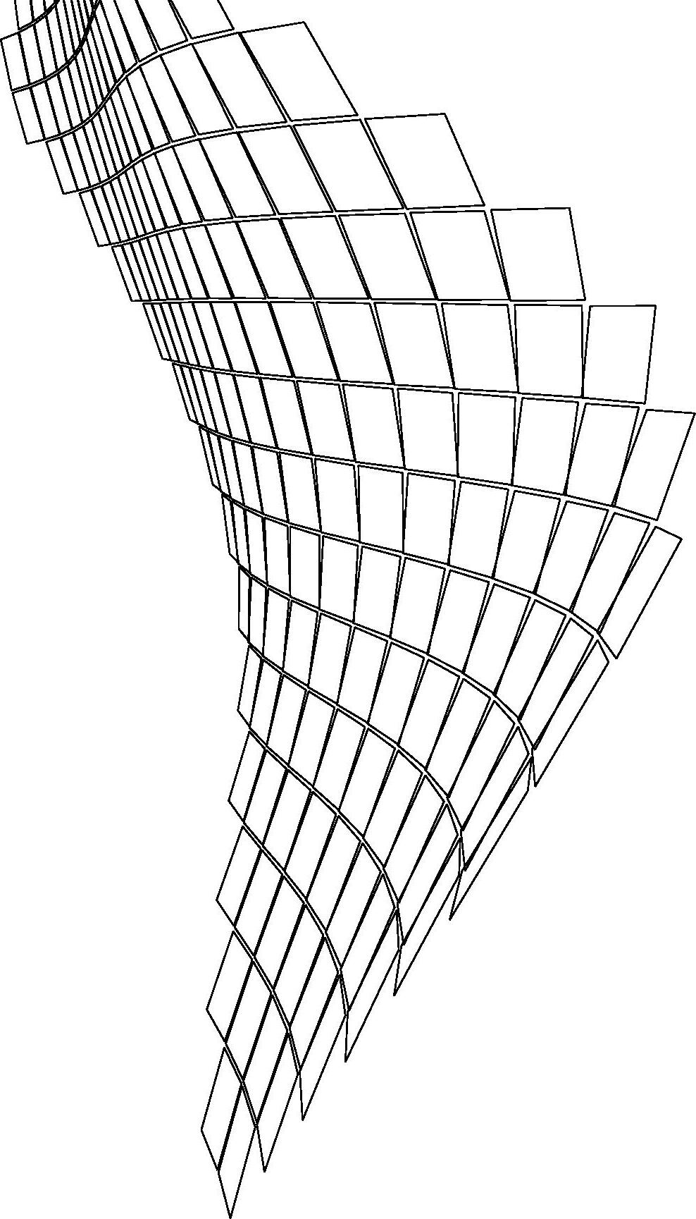
DAYLIGHTING ANALYSIS
High glare

High useful illuminance

Climatestudio analysis to decide the facade design - vertical fins vs. perforated panels
38
Sun
Signage People
Hagwon
Floors
Staggered
Visual connection
SOCIAL SPACES


39 HAGWON FLOOR THREE PLAN


40 FACADE PANEL FIXING DETAIL
1. Metal grating for support
2. Supporting member with angle cleat
3. C channel with hook
4. Horizontal & vertical supporting members
5. Perforated metal panels
6. Perforated panel with solid signage
1 2 3 4 6 7 5
7. Solid panel with perforated signage

PROPOSED HAGWON IN SITE CONTEXT

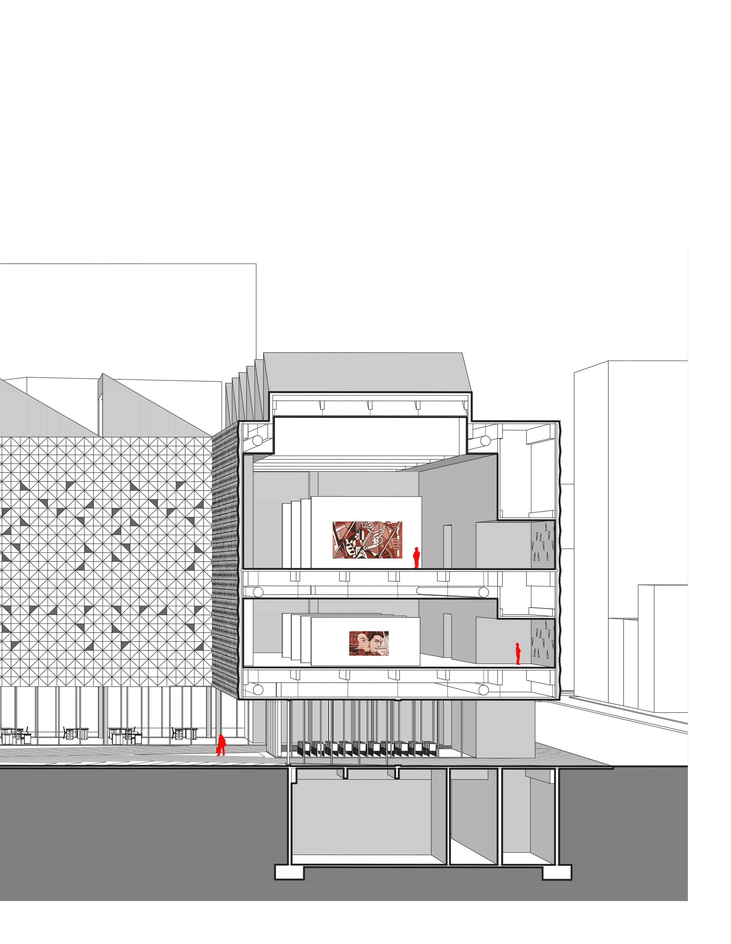
41 EAST-WEST SECTIONAL PERSPECTIVE
BUILDING MODEL 1/8” = 1’ SCALE

SECTIONAL DETAIL MODEL 1/2” = 1’ SCALE


42


PROFESSIONAL WORK
This section consists of work done during my internships and jobs in India, followed by a section of academic works. All the work done is under the guidance of professional architects and designers. The experience helped me develop proficiency in softwares such as AutoCAD, SketchUp, Photoshop, Rhino, Revit, Microsoft Office suite etc. alongside polishing my soft skills.
ASIAN F1 F2 F3 F4 F5 JOHNSON X12MM JOHNSON THICKNESS JOHNSON X12MM ASCOLI KAJARIA 800X800X12MMTHICKNESS W1 W2 W3 W4 W5 ASIAN ASIAN JOHNSON BIANCO S1 S2 S3 S4 S5 JOHNSON X12MM JOHNSON THICKNESS JOHNSON X12MM ASCOLI KAJARIA 800X10X12MMTHICKNESS ASIAN C1 C2 C3 ASIAN ASIAN W6 ASIAN C4 ASIAN D1 KITCHEN 3735 x 2835 LIVING AREA 6000 x 3650 W5 W1 D1 D2 W5 W1 W1 W2 W2 D5 D2 LOBBY 7060x2100 UP DN FIRE DUCT OP1 OP1 D6 W1 KITCHEN 2500 x 3350 W5 W1 D1 D2 W2 OP1 ELECTRICAL DUCT D7 D3 TOILET 2500 x 1500 TOILET 2500 x 1500 TOILET 2500 x 1500 TOILET 2500 x 1500 W1 W3 W3 W3 W3 LIVING ROOM 3370 x 6000 BEDROOM 3350 x 4450 BEDROOM 3385 x 4100 LIVING ROOM 3370 x 6000 BEDROOM 3630 x 4355 BEDROOM 3630 x 4355 D4 D4 D4 D4 1 M WIDE PASSAGE 1 M WIDE PASSAGE 1 M WIDE PASSAGE LIFT 1500x1800 970 MM WIDE BALCONY 970 MM WIDE BALCONY 970 MM WIDE BALCONY MAIN LANDING ALL EQUAL TREAD 300 RISER 150 MID-LANDING 1500 300 EQ EQ 1800 3000 MS RAILING 50 MM 635MM WIDE CHAJJA ABOVE 600MM WIDE CHAJJA ABOVE 635MM WIDE CHAJJA ABOVE 600MM WIDE CHAJJA ABOVE OP2 OP3 OP2 OP2 3630 1065 2730 4355 945 115 2785 1000 1350 3905 760 1615 3370 3255 2385 2500 115 230 1255 520 800 760 2385 2500 115 3350 1255 520 800 3630 1065 2730 4355 945 115 2785 1000 2500 765 1350 3905 1615 3370 3255 2845 3105 585 1000 2100 1295 1570 835 350 1270 885 1200 1200 945 3385 4100 1750 1750 885 990 770 1500 3650 1075 3535 2450 900 2500 900 2500 2835 1685 MS RAILING 50 MM MS RAILING 50 MM MS RAILING 50 MM 2235 770 1500 3350 925 2950 4450 OP4 OP5 OP5 3350 4090 3485 2385 3460 3615 3815 3100 1485 2730 3180 1730 1730 1270 2615 3485 4090 7660 4815 2100 4815 2730 2730 1350 KITCHEN 2500 x 3350 230 C1 C2 C3 C4 C5 C6 C7 C8 C9 C10 C11 C15 C12 C13 C14 C16 C17 C18 S2 S3 C19 C20 C21 C22 C23 S4 C24 C25 C26 C27 C28 C29 C30 3765 600MM WIDE CHAJJA ABOVE 600MM WIDE CHAJJA ABOVE 600MM WIDE CHAJJA ABOVE 600MM WIDE CHAJJA ABOVE 575 1500 400 450 282 600MM WIDE CHAJJA ABOVE 1 2 3 4 5 6 7 8 9 10 11 21 20 19 18 17 16 15 14 13 12 2500 765 875 730 330 460 840 440 S1 F1 W1 C1 S2 F2 W2 C2 S3 F3 W4 C1 S5 F5 W5 C1 S2 F2 W3 C3 S2 F2 W3 C3 S5 F5 W5 C1 S5 F5 W5 C1 S5 F5 W5 C1 S3 F3 W4 C1 S3 F3 W4 C1 S2 F2 W3 C3 S2 F2 W3 C3 S2 F2 W2 C2 S2 F2 W2 C2 S4 F4 W6 C4 S4 F4 W6 C4 S4 F4 W6 C4 150 MM LEDGE WALL 150 MM LEDGE WALL 150 MM LEDGE WALL B A A' B' 250 250 470 1000 2815 18 MM EXT. WALL PLASTER 12 MM INT. WALL PLASTER 18MM THK KOTA AS TREAD STONE 18MM THK KOTA AS RISER STONE MORTAR 12MM THK 18MM THK KOTA STONE FLOOR 150 MM THK RCC SLAB RUBBLE PACKING 230X600 MM ANCHOR BEAM 120X30MM METAL FIXING PLATE 18MM THK KOTA AS TREAD STONE 25MM SS FLAT FOR SUPPORT 25MM SS ROD 25MM SS FLAT FOR HANDLE BAR GRANITE SKIRTING 18MM THK HALF ROUND FINISH GRANITE COUNTERTOP 70 MORTAR JOINT CERAMIC DADO TILES KADAPPA BASEPLATE40MM THK BRICKBAT COBA IN 200MM SUNK KADAPPA STONE PLATE GRANITE FACIA PLATE SAND SCREEDING 450 640 840 18MM THK KOTA AS TREAD STONE 18MM THK KOTA AS RISER STONE MORTAR 12MM THK 18MM THK KOTA STONE FLOOR 150 MM THK RCC SLAB RUBBLE PACKING 230X600 MM ANCHOR BEAM 120X30MM METAL FIXING PLATE 18MM THK KOTA AS TREAD STONE 25MM SS FLAT FOR SUPPORT 25MM SS ROD 25MM SS FLAT FOR HANDLE BAR GRANITE SKIRTING 18MM THK HALF ROUND FINISH GRANITE COUNTERTOP 70 MORTAR JOINT CERAMIC DADO TILES KADAPPA BASEPLATE40MM THK BRICKBAT COBA IN 200MM SUNK KADAPPA STONE PLATE GRANITE FACIA PLATE SAND SCREEDING 450 640 840 45 TYPICAL FLOOR PLAN
COUNTER DETAIL Construction drawings for a 7 storey RCC construction Residential building in Mumbai (dimensions in mm)
STAIRCASE DETAIL
D7 W3 OP2 LIFT METER ROOM SOCIETY OFFICE LIFT LIVING ROOM KITCHEN LIVING ROOM ELECTRIC DUCT D1 OP2 LIFT ELECTRIC DUCT OP2 LIFT ELECTRIC DUCT OP2 LIFT ELECTRIC DUCT OP2 LIFT ELECTRIC DUCT OP2 LIFT ELECTRIC DUCT OP4 OP2 ELECTRIC DUCT GROUND LEVEL +/- 0.00 M LVL STILT LEVEL +0.30 M LVL FIRST FLOOR LVL +3.30 M LVL SECOND FLOOR LVL +6.60 M LVL THIRD FLOOR LVL +9.90 M LVL FOURTH FLOOR LVL +13.20 M LVL FIFTH FLOOR LVL +16.50 M LVL SIXTH FLOOR LVL +19.80 M LVL SEVENTH FLOOR LVL +23.10 M LVL TERRACE FLOOR LVL +26.40 M LVL MACHINE ROOM LVL +28.50 M LVL MACHINE ROOM TOP LVL +31.40 M LVL MACHINE ROOM SUNK 200MM 600 D7 450 575 2750 600 3300 3300 3300 3300 3000 1050 450 2550 1700 300 1200 1950 2700 150 450 670 3300 3300 300 600 3300 2402 230 600 D7 D7 D7 D7 D7 D1 D7 300 SUNK 200MM LIVING ROOM KITCHEN LIVING ROOM OP4 D1 LIVING ROOM KITCHEN LIVING ROOM OP4 D1 LIVING ROOM KITCHEN LIVING ROOM OP4 D1 LIVING ROOM KITCHEN LIVING ROOM OP4 D1 LIVING ROOM KITCHEN LIVING ROOM OP4 D1 LIVING ROOM KITCHEN LIVING ROOM OP4 D1 SUNK 200MM SUNK 200MM SUNK 200MM SUNK 200MM F C E D G B H L P F C E D G H L P W3 W3 W3 W3 W3 W3 MS RAILING PARAPET ISLB 150x80 FOR SUPPORT 46 SECTION AA

Rendered on Enscape
NORTH FACADE DESIGN


Rendered on V-ray
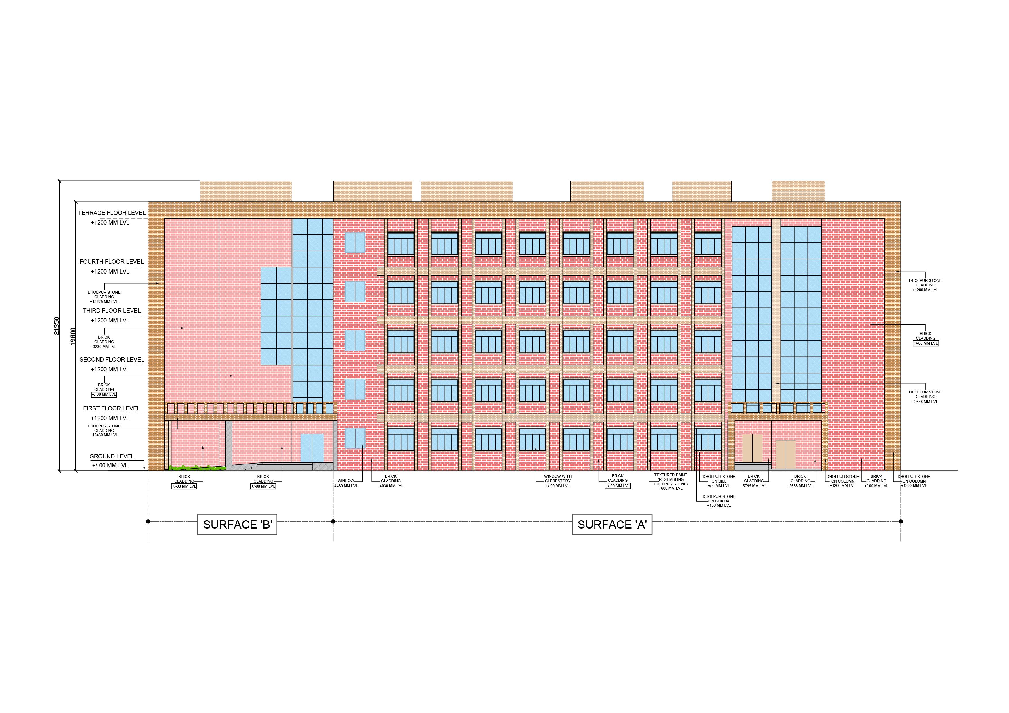

Planning & Facade design for the Indian Agricultural Research Institute in Pune (under supervision of Chief Architect)
47
FOR INTERIOR DESIGN PROJECTS
VISUALIZATION
Brick
Dholpur stone


Rendered on V-ray
LADIES TOI. PORCH WASH BASIN UP LVL ± 00mm UP LVL ± 00 mm UP LVL ± 00mm 00mm UP F.H.C. LADIES TOI. W.C PORCH ENT. FOYER LVL 600mm F.H.C. GENTS TOI. WASH PLANTER ESCAPE PLANTER RAMP STORE TOI. RAMP TOI. UPLVL± 00mm LVL 150mm LVL 600 mm LVL 150mm UP LVL ±00 mm STRUCTURAL FACADE ELEMENT FACADE ELEMENT STRUCTURAL 6230X4215MM 3899X6230MM 1800X 3600X3150MM 41530 5837 2673 3658 3157 3000 5795 26105 4030 3230 5302 4374 5302 4030 5795 3157 2638 5837 41565 9227 16320 3530 3400 6425 6495 6459 6495 3234 6495 3227 18955 3230 6325 6595 3400 3530 9460 9460 18690 18690 9460 9230 28910 W4 W1 W1 W2 W2 W1 W4 W2 W.C ELEC.DUCT ELEC.DUCT GENTS TOI. URINALS WASH BASIN DUCT HIDING COLUMN 48
KEY PLAN
stone
(716) 936-4210
ruchiras@buffalo.edu
www.linkedin.com/in/ruchirasardesai