FALL PROTECTION SYSTEMS AND PROTECTIVE EQUIPMENT - 2021
FALL PROTECTION SYSTEMS AND PROTECTIVE EQUIPMENT
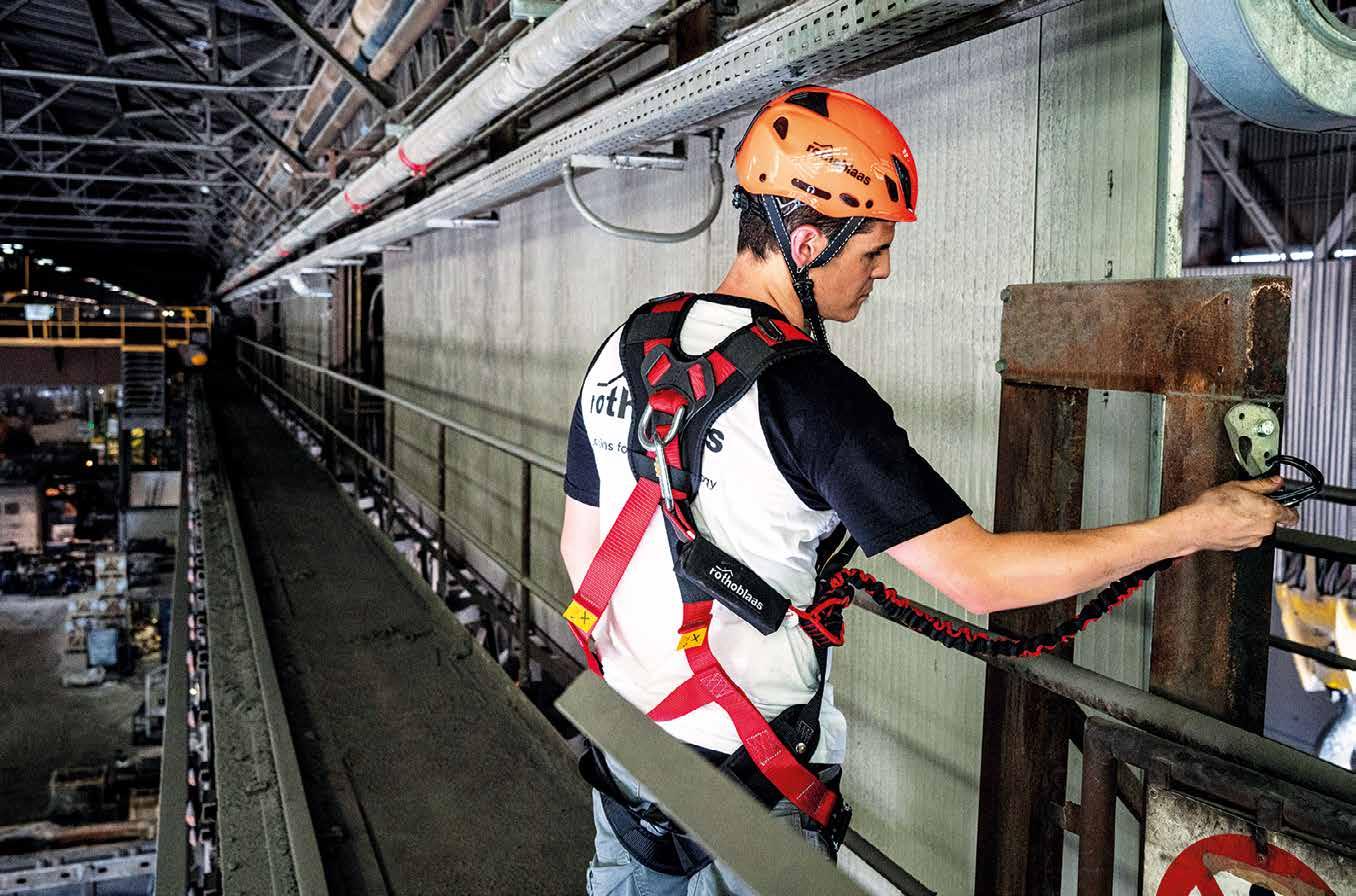
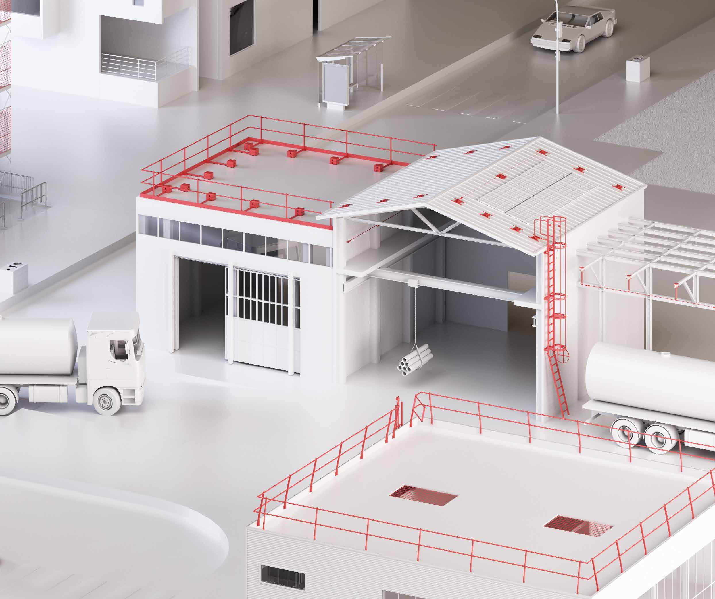
SAFETY, FOR INDUSTRY AND CONSTRUCTION
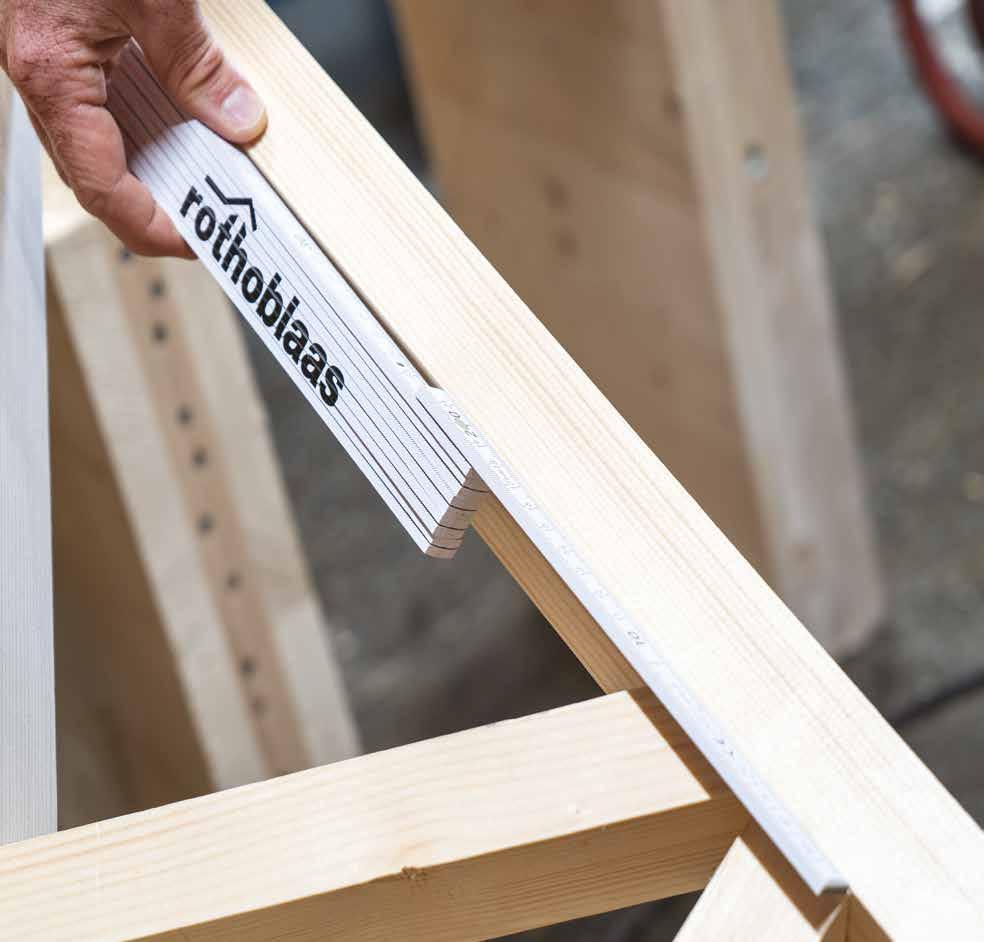
PATROL+BLOCK
PATROL WALL
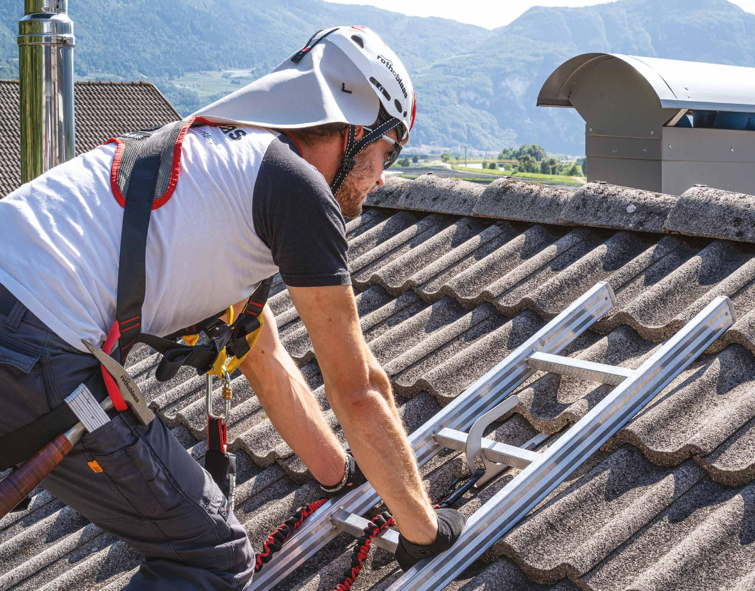
VERTIGRIP ON LADDER
V-RAIL
SIANK
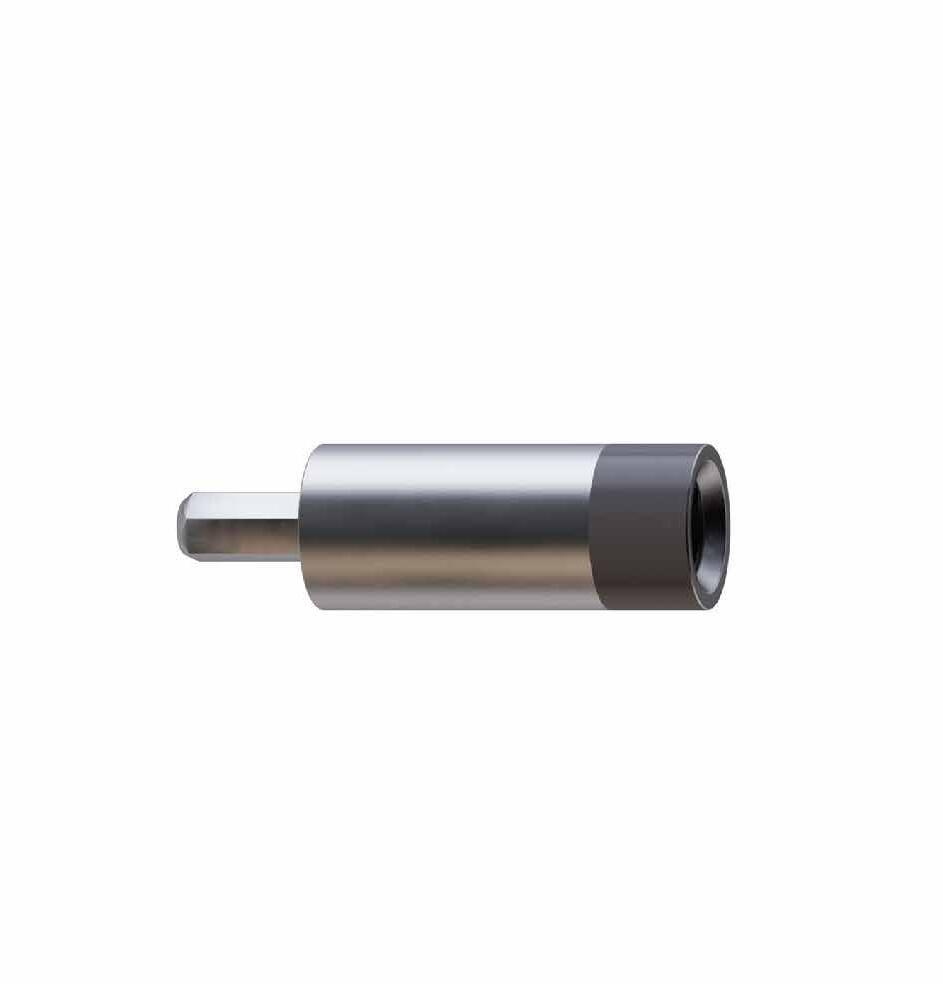
GLUEANCHOR
Seamo+
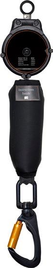
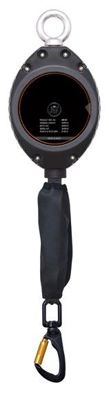
DISCENSORI-AUTOBLOCCANTI
DISCENSORI-POSIZIONAMENTO
accessori
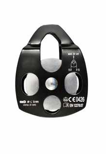
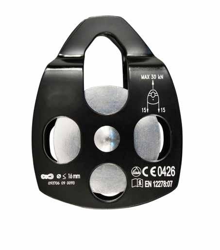
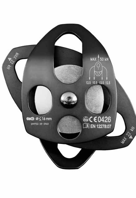
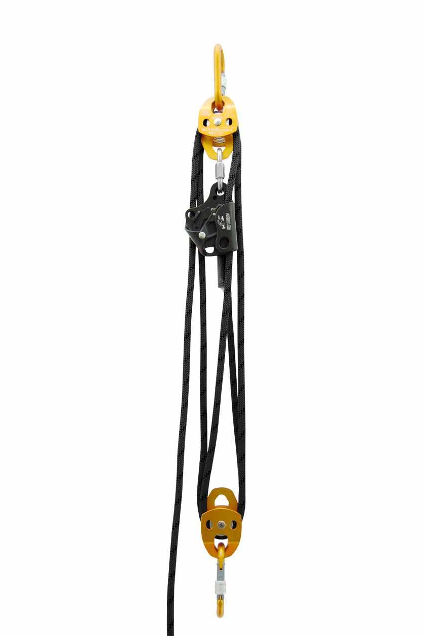
carrucole
corde e accessori
ancoraggi
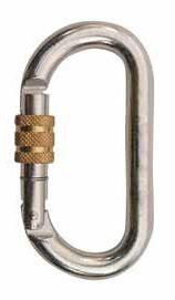
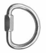
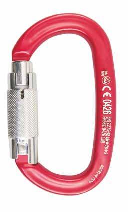
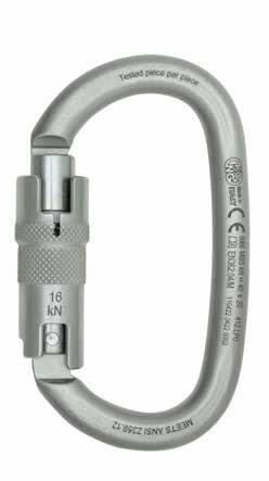
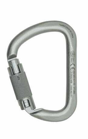
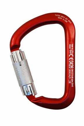
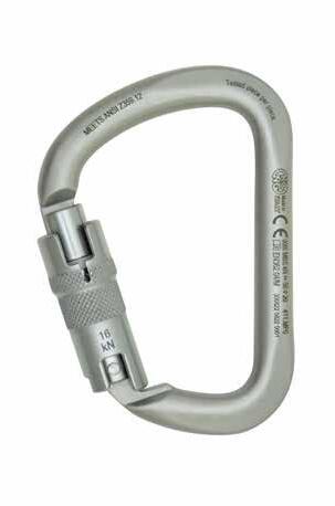
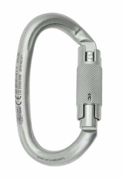
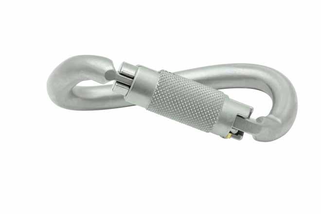
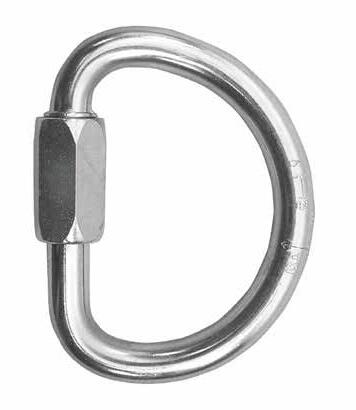
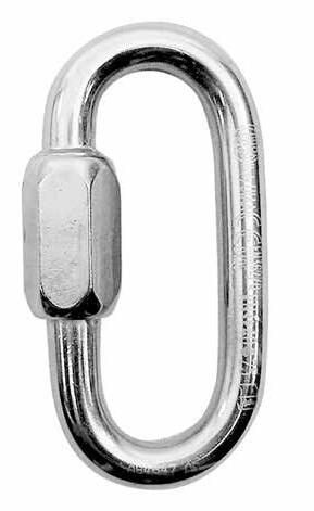
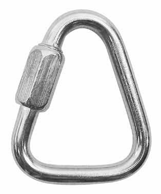
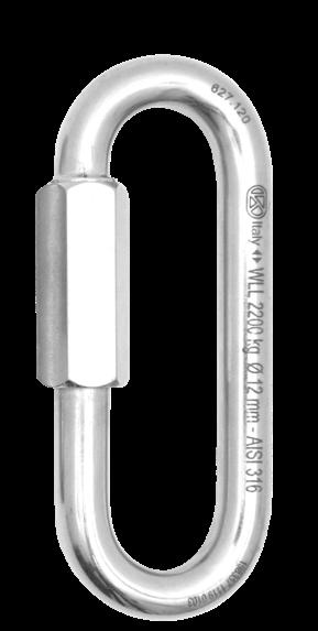
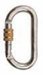
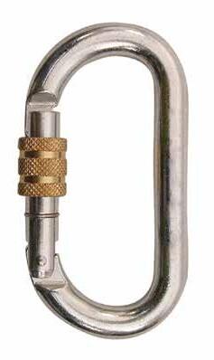
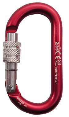
connettori
IN THE SERVICE OF SECURITY
IN-HOUSE PRODUCT DEVELOPMENT AND TESTING
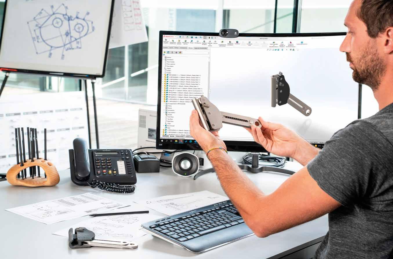
When developing a new product, we directly follow all stages: market analysis, feasibility studies, planning and design, functional and effectiveness tests, including tests on fixings and substrates. All tests are carried out using the replication of a real roof.
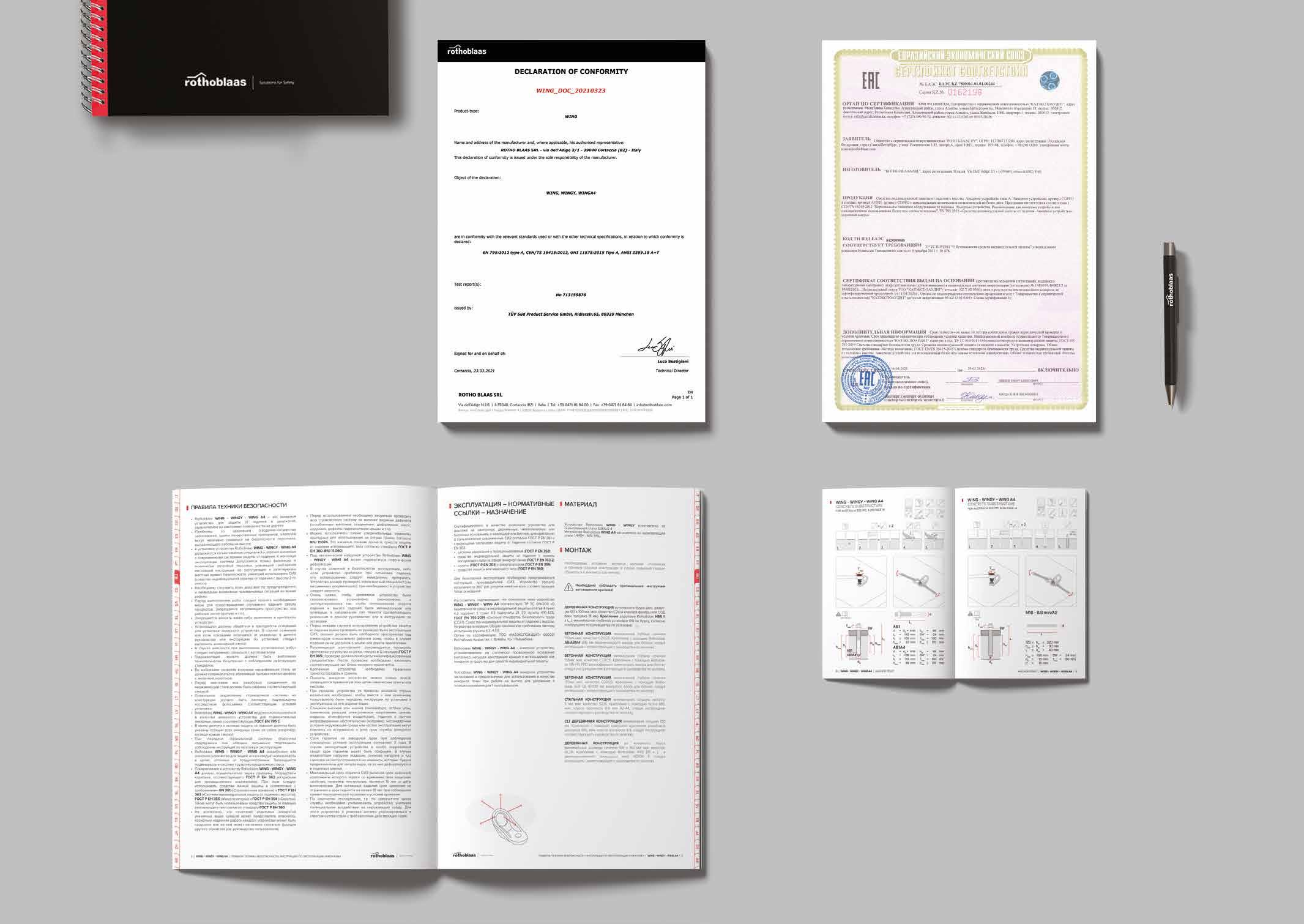
EXTERNAL CERTIFICATION
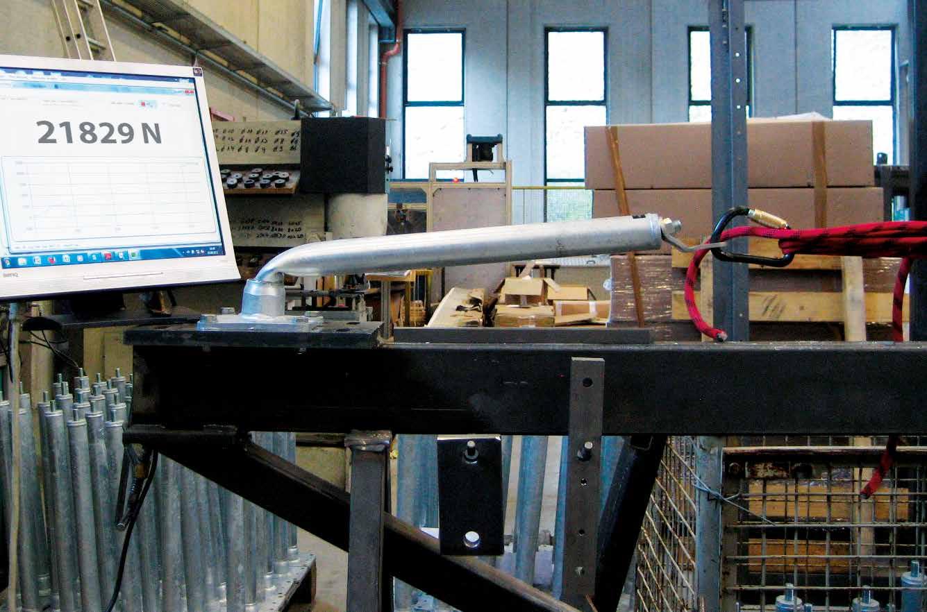
In the certification process of our products, we are followed by an external certification body. The tests are carried out on the different types of substructure according to current technical standards, which include deformation tests, dynamic tests, static tests, failure tests and corrosion tests. The certification also takes into account the technical documentation, which must be drawn up according to certain characteristics.
ONLINE DOCUMENTATION
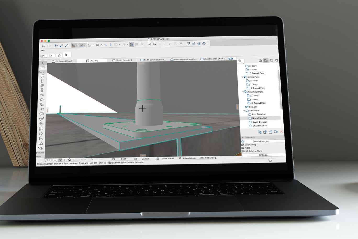
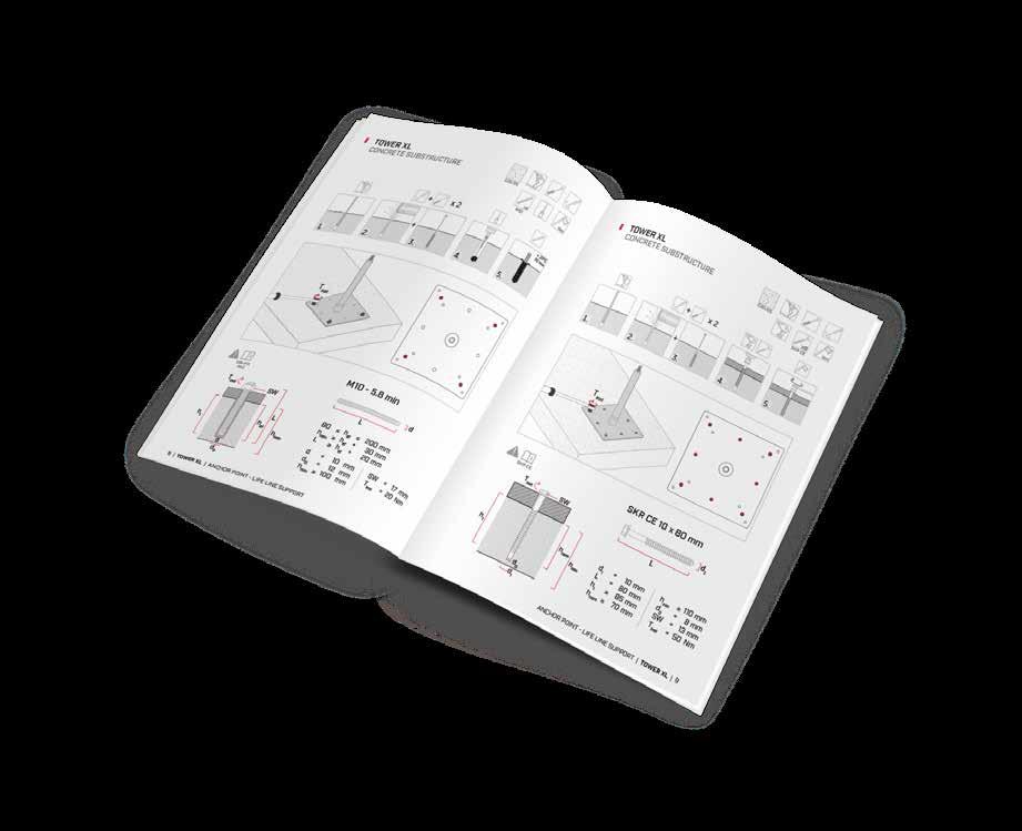
On our website you will find all the documentation relating to our products, in various languages: installation and user manuals, technical data sheets, certificates, BIM/ CAD objects, assembly videos, software for calculating and verifying lifelines and support for the correct preparation of an estimate. Our safety solutions are designed together with the substructure fixings and waterproofing systems, so that we can guarantee professional installation.
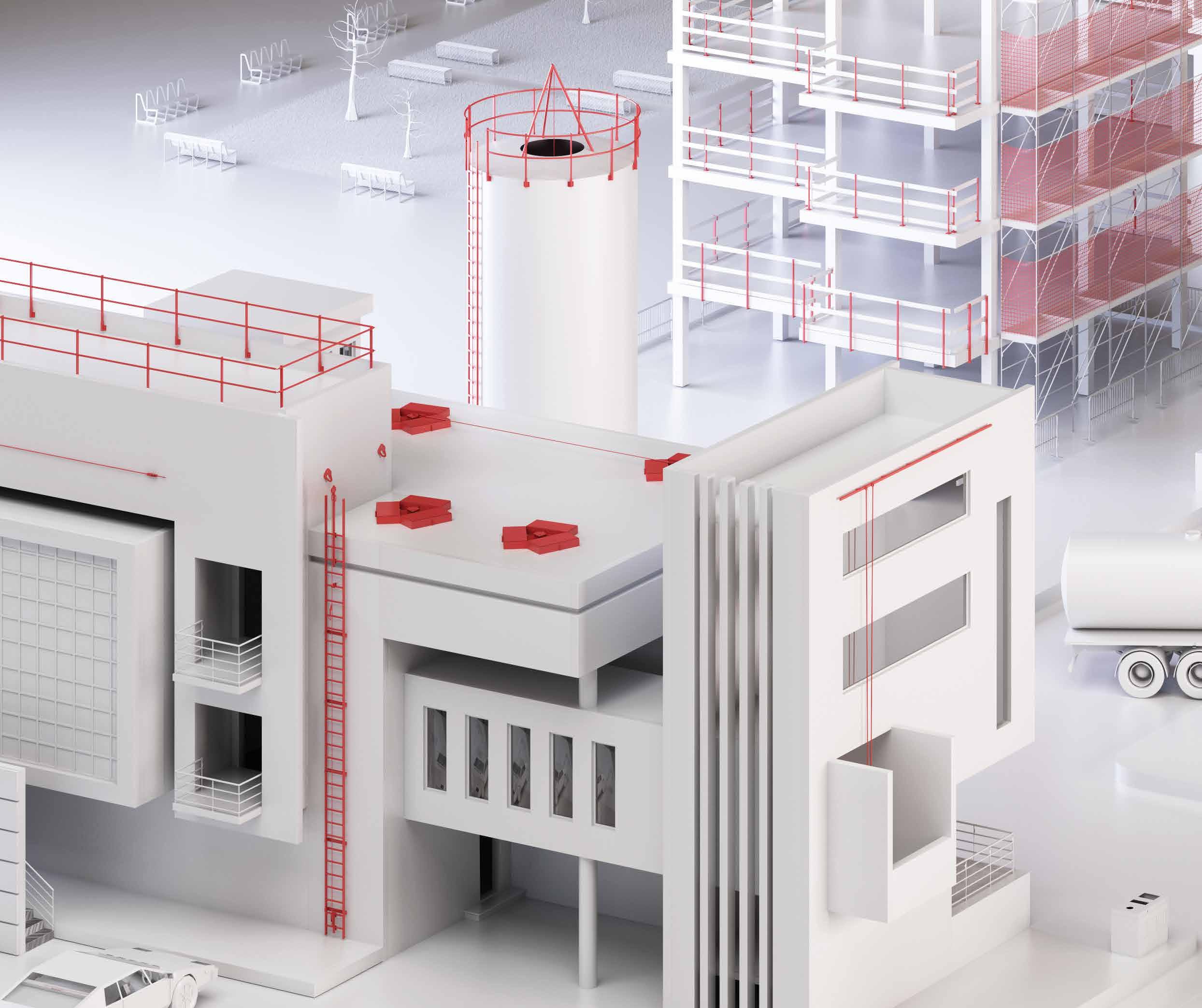
WHO USES OUR PRODUCTS?
INTEGRATED SOLUTIONS FOR INDUSTRY
Our product range is constantly being updated in order to meet the constant demands of the market. Whether you are involved in industrial safety, specialised distribution of fall protection systems, renewable energy or plant safety, you will find the right solution for you.
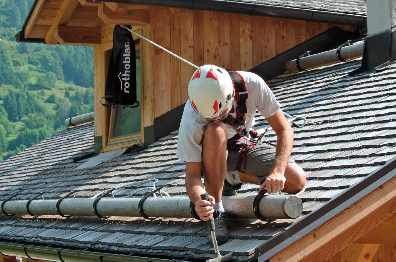
SYSTEMS AND PRODUCTS FOR SITE SAFETY
Our products are ideal for ensuring safety at work for builders of timber houses and large glulam and CLT structures, carpenters, tinsmiths and building renovation professionals.
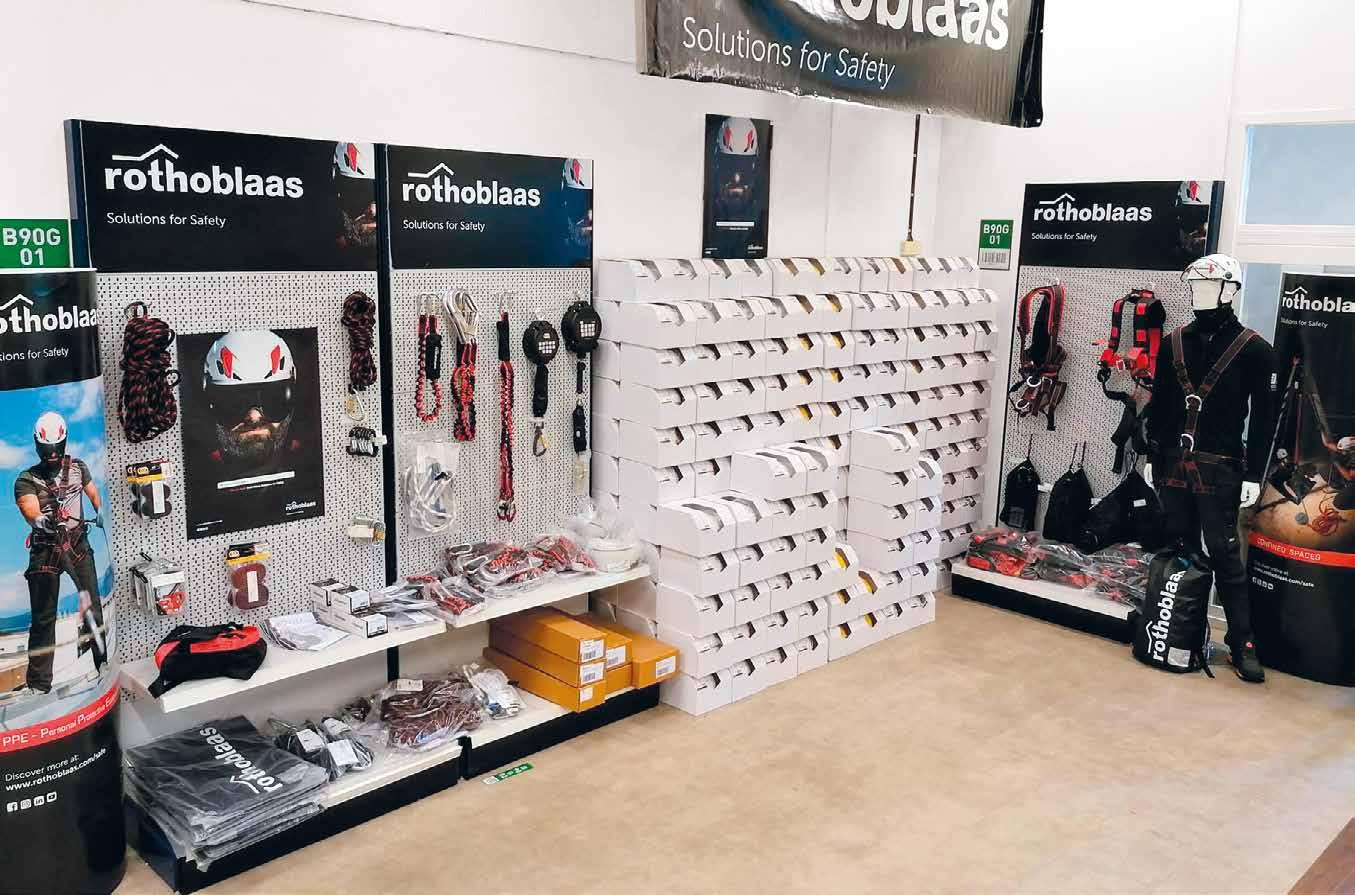
RESALE-FRIENDLY DISPLAY
Do you have an exhibition space? We provide you with the tools to present your products in the best possible way in your building materials shop, hardware shop or retail outlet. Metal displays, communication tools and gadgets for your customers will help you maximise your business.
seamo
siank4
siankint
COMPLETE RANGE
LIFELINE AND RAIL SYSTEMS
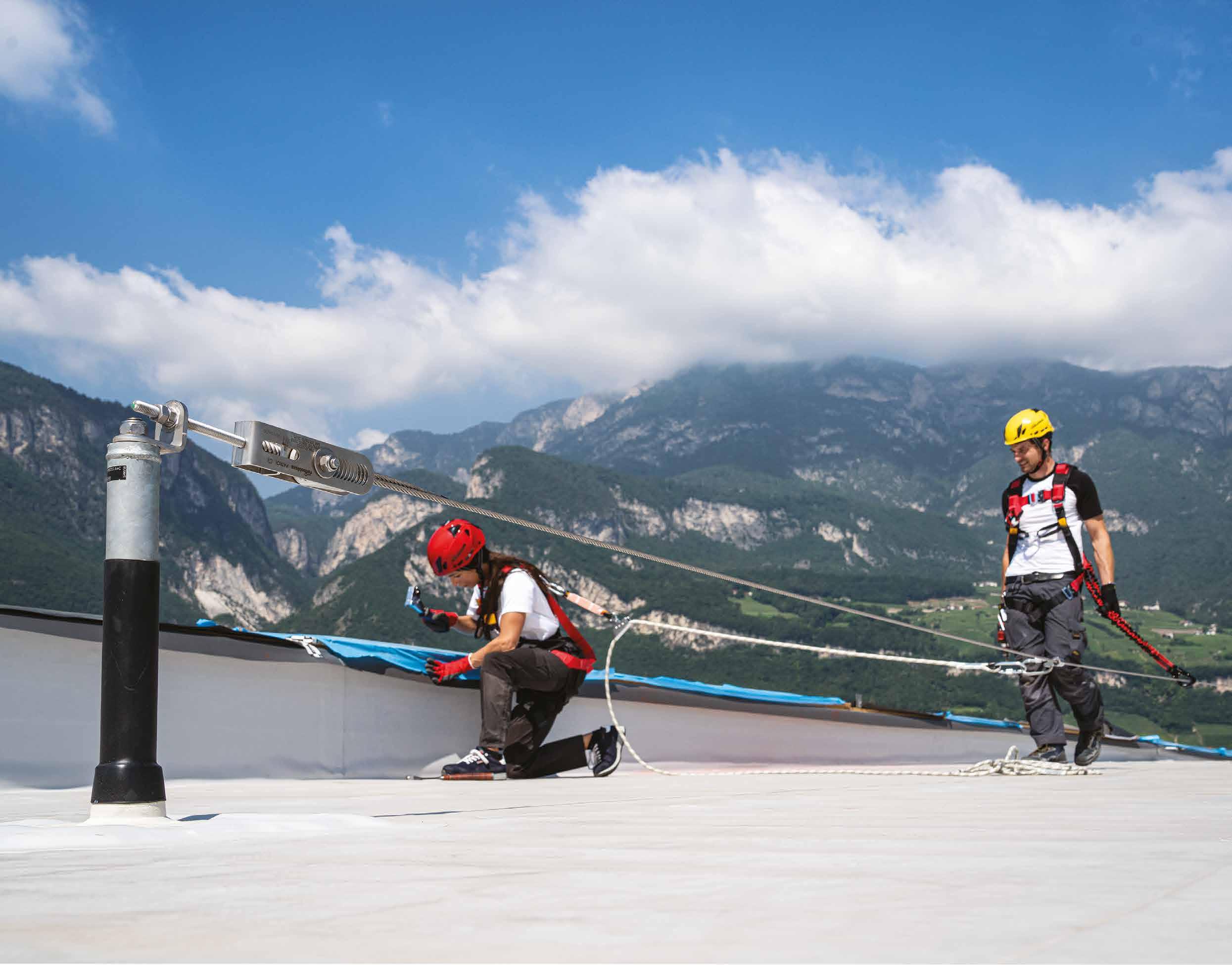
Our lifeline systems meet every design requirement: rope or rail, fixed or temporary, horizontal or vertical.
They are convenient systems for the operators: they allow easier movement than single points, are comfortable in use thanks to the through systems and offer the possibility of securing up to 4 operators at the same time.
ANCHOR POINTS
Anchor points are the alternative or complement to lifelines. Those in the Rothoblaas Solutions for Safety range are designed to meet different construction requirements and to adapt to substrates made of various materials.
Designed for use with different techniques (anti-fall, restraint, suspension), they allow direct connection with the PPE, offering safety to a number of operators that can vary from 1 to 4 depending on the type of device.
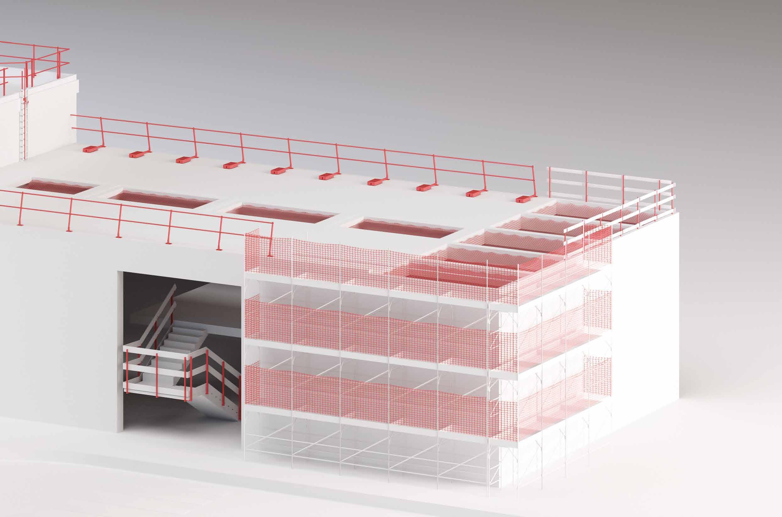
COLLECTIVE PROTECTION
Collective Protective Equipment (CPE) include all temporary or permanent devices designed to protect more than one operator from the risk of falling. These include, for example, railings, textile and metal nets, ladders with and without cages, steps and other types of protection.
Thanks to the CPE it is possible to work safely even without PPE.
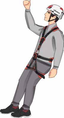
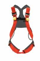
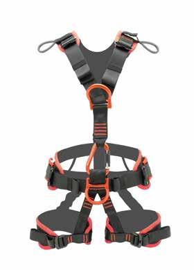
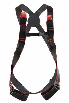
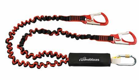
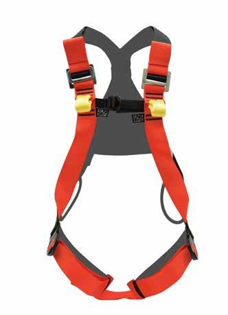
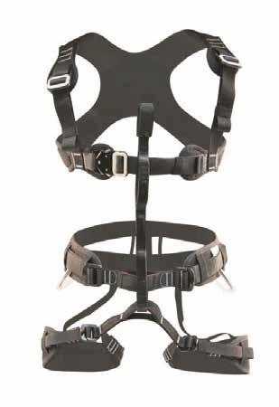
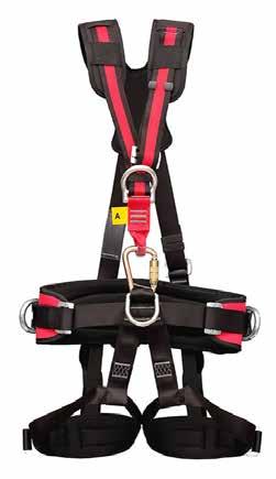
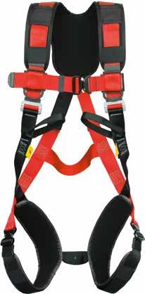
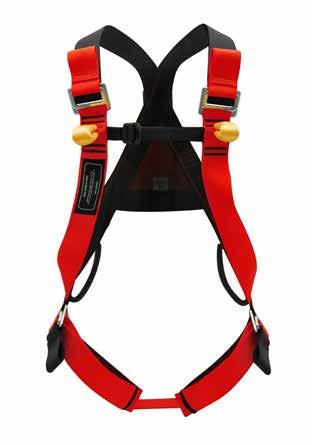
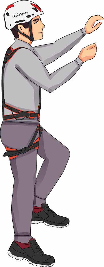
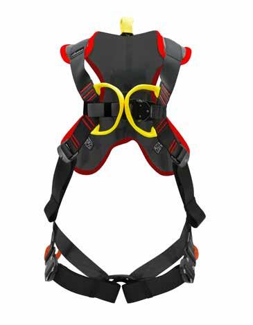
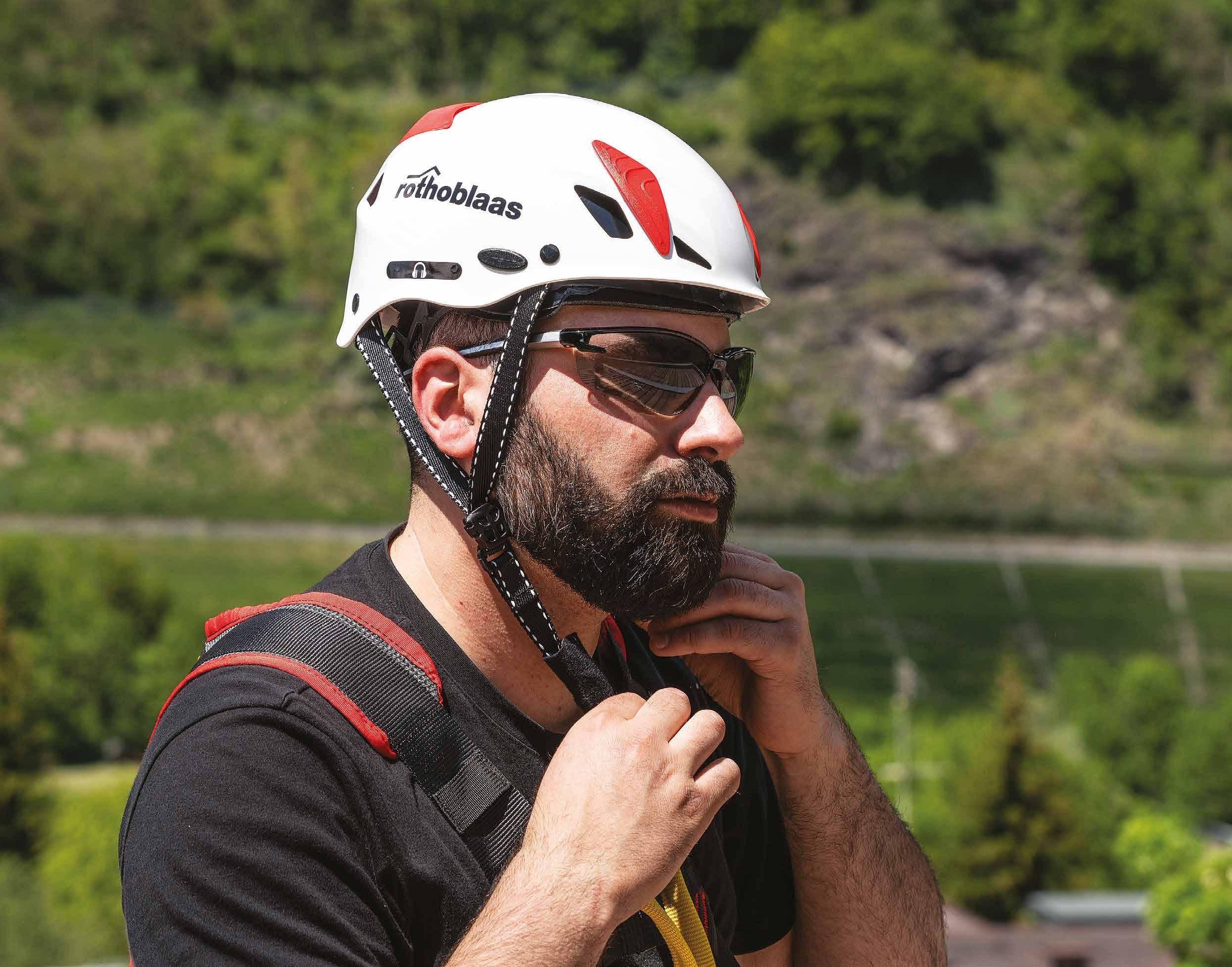
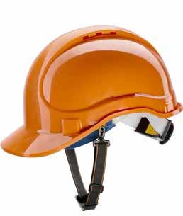
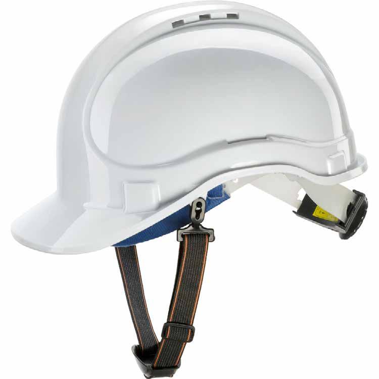
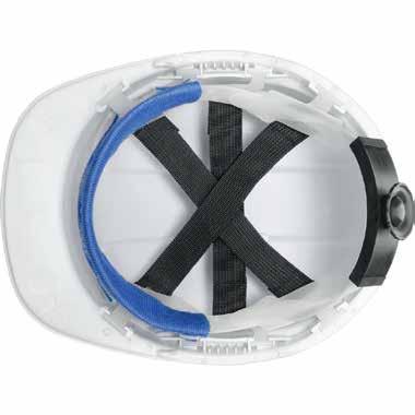
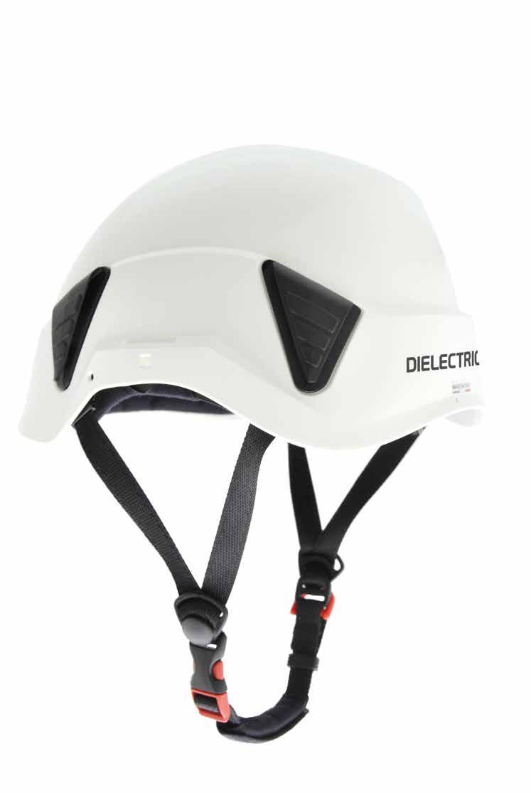
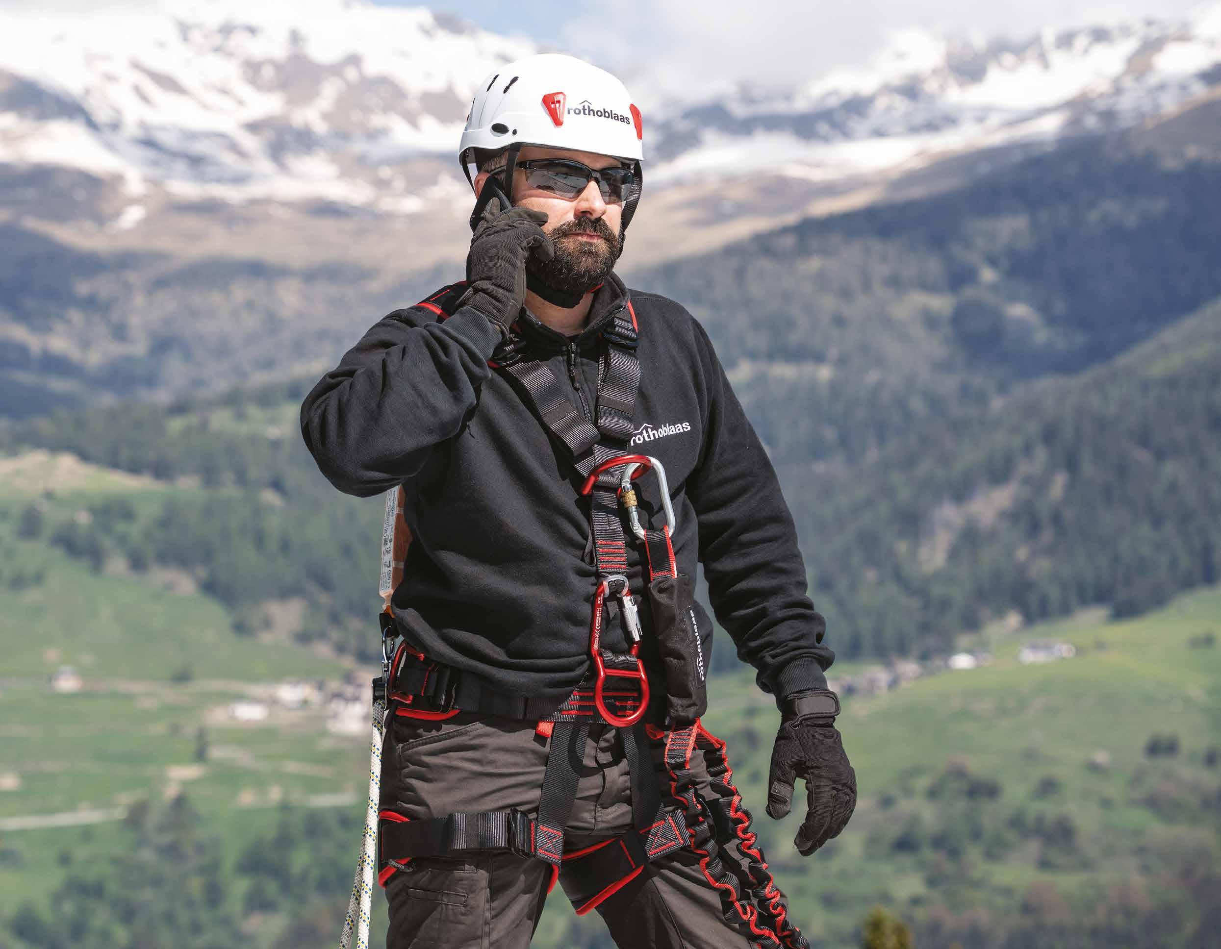
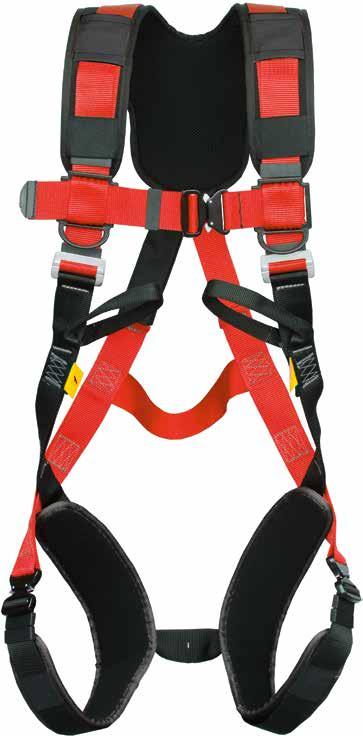
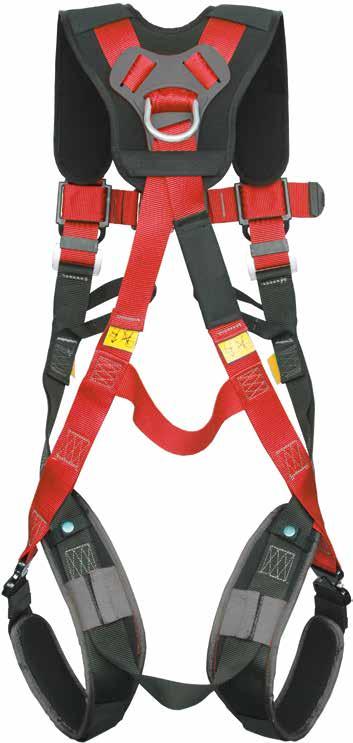
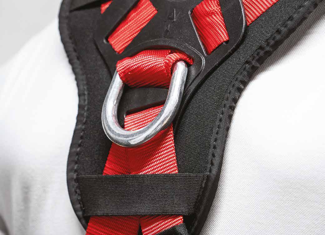
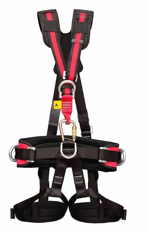
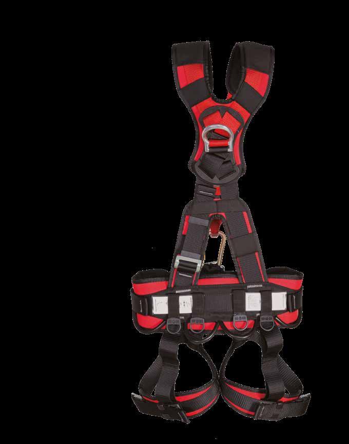
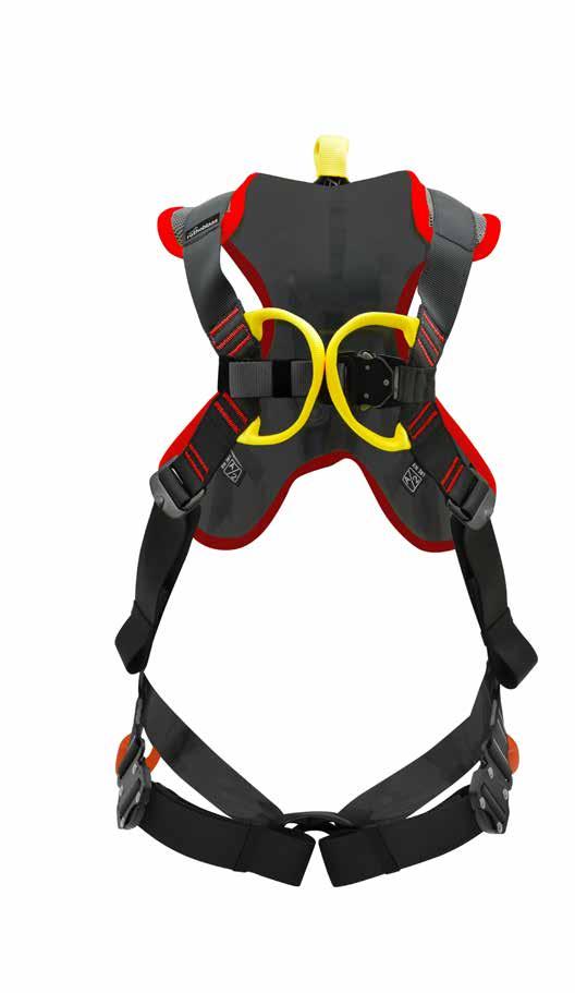
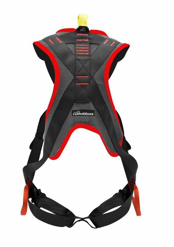
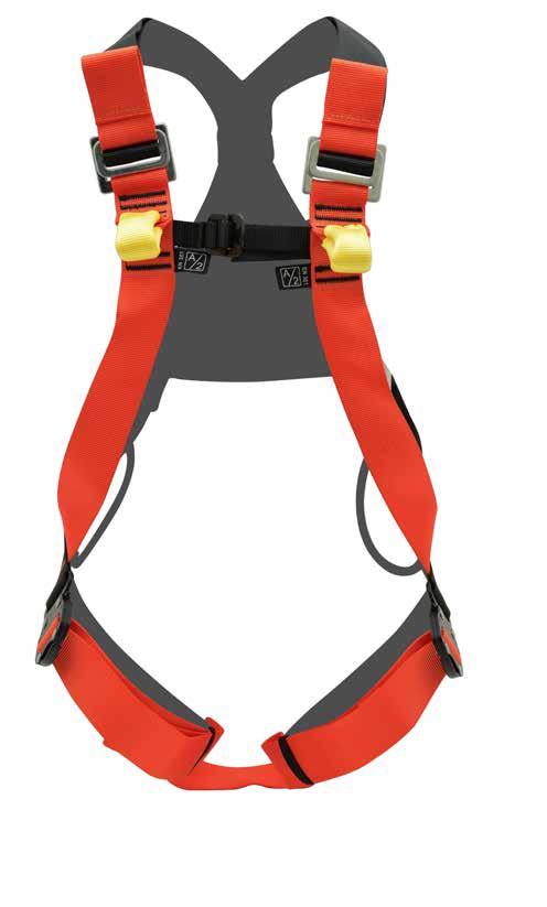
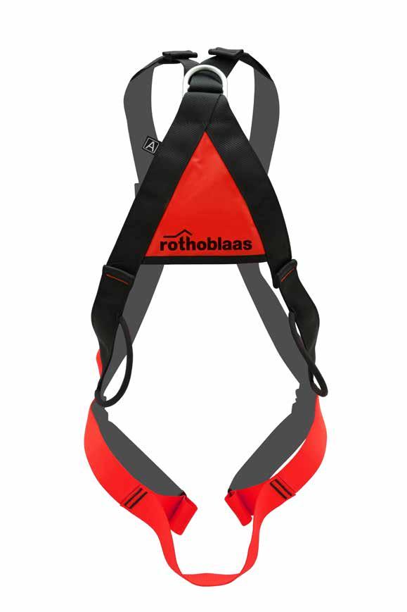
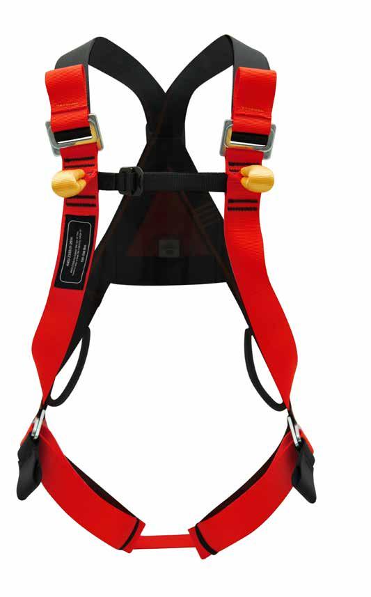
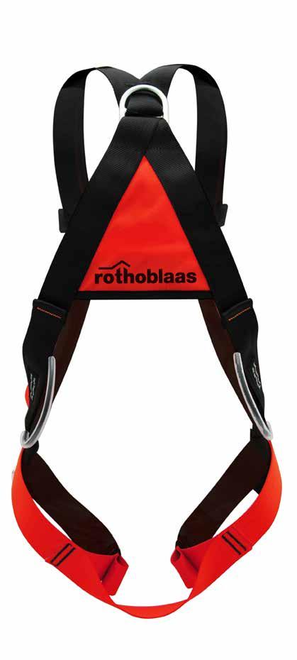
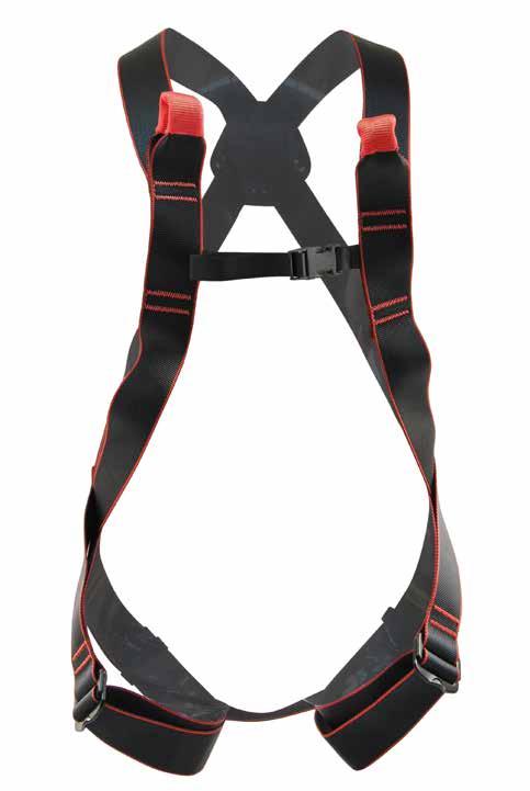
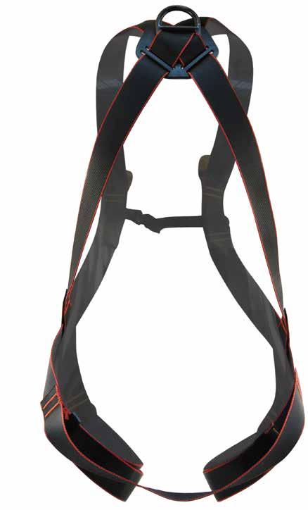
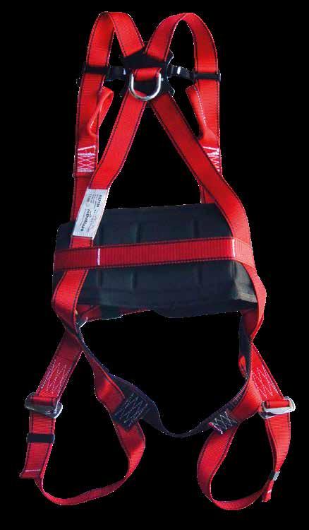
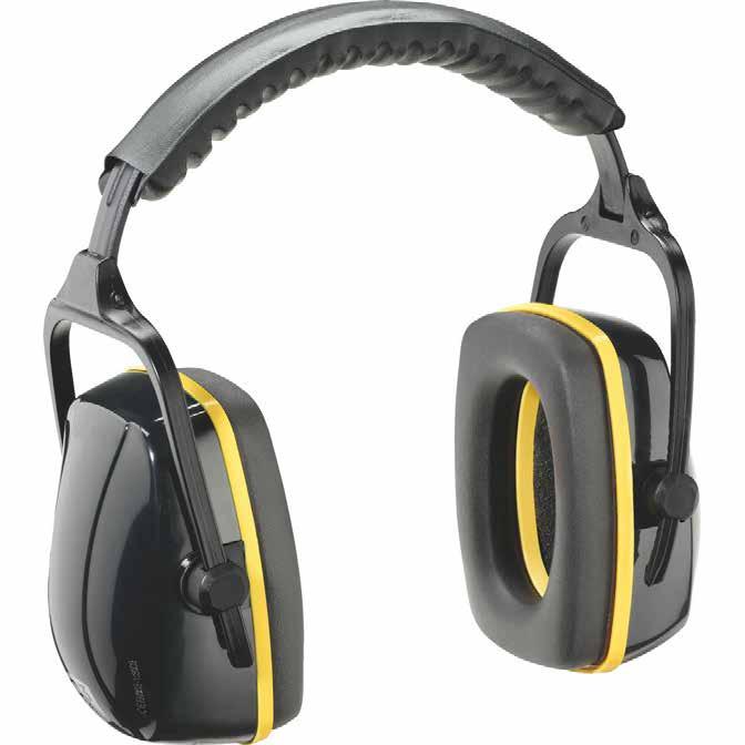
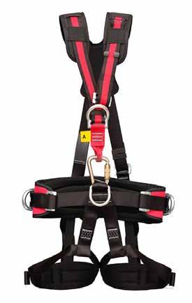
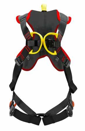
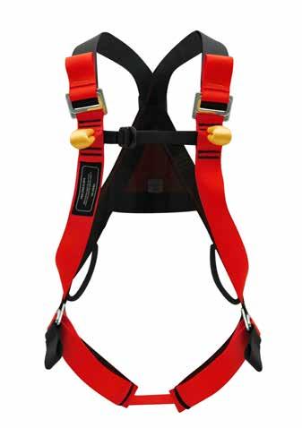
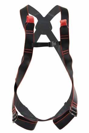
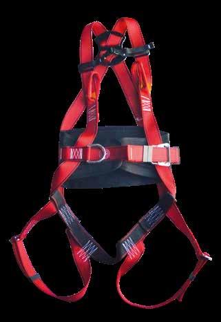
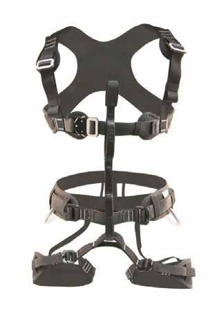
PERSONAL PROTECTIVE EQUIPMENT
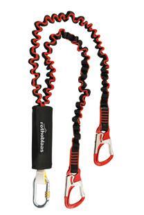
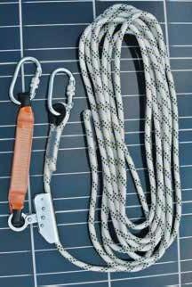
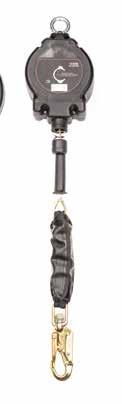
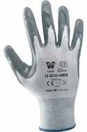
Personal Protective Equipment (PPE) includes any type of equipment designed to be worn or used by the workers in order to protect them from risks that could threaten their safety while carrying out operations at height.
ONLINE RESOURCES
COMPLETE MULTILINGUAL DOCUMENTATION
On our website we provide documentation and tools to simplify your work. The documents are easily accessible, either by scanning the QR codes you find in the catalogue next to the products, or through the advanced search function on the site, using the appropriate filters.
Among the available documentation you will find:
• catalogue
• technical data sheets
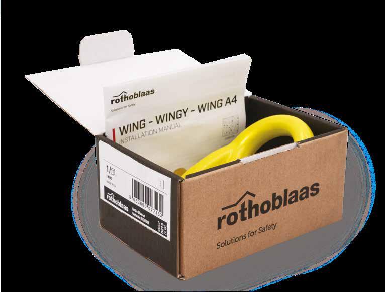
• installation manuals and safety regulations
• certificates
• declaration of conformity
• technical data
To support your planning, you will also find on our website:
• BIM and CAD objects
• calculation software for lifeline
• video available on our YouTube channel
FILTER RESET
MATERIAL
zinc-plated steel
stainless steel
A2 stainless steel
A4 stainless steel
aluminium alloy
plastic materials
NUMBER OF USERS
SUBSTRUCTURES
timber concrete
steel
metal sheet/panel
continuous metal roof
fixed ladder
PVC
bituminous
green/gravel flat roof
PRODUCT
DECLARATION
CERTIFIED PRODUCTS
Our products are tested in the presence of certification bodies that validate the tests performed and certify them according to the relevant standards.
The marking contains normative references, product traceability and information for correct use.
The documentation for the devices (declarations of conformity, certificates, installation manuals and safety regulations) are available on our web site www.rothoblaas.com, easily traceable thanks to the QR codes found inside this catalogue.
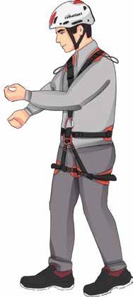
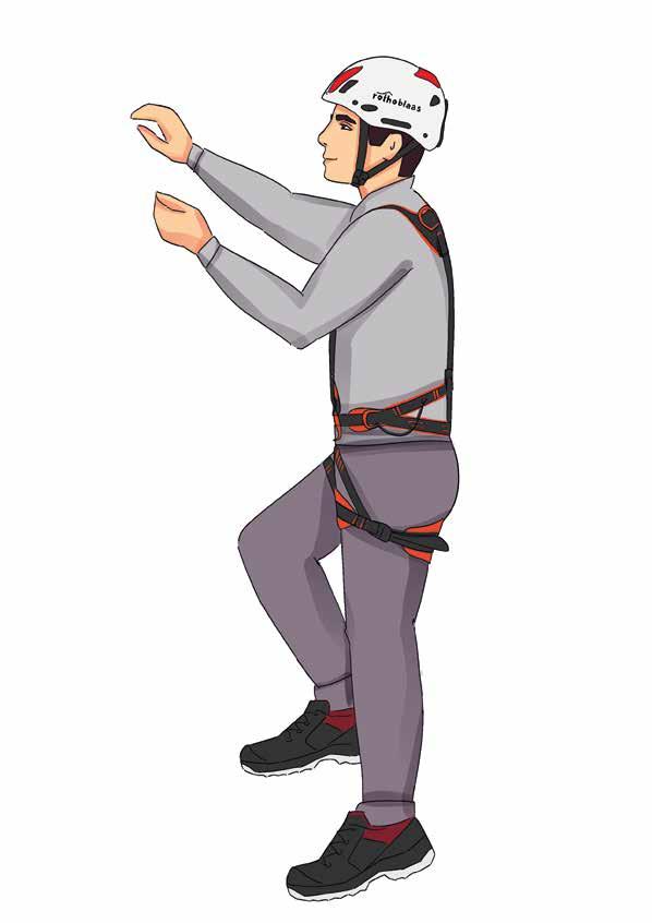
TECHNIQUES FOR WORK AT HEIGHT
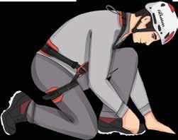
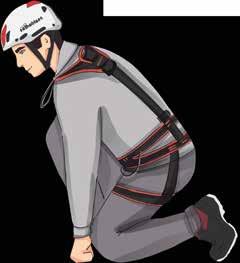
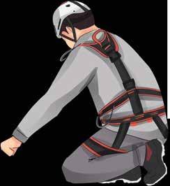
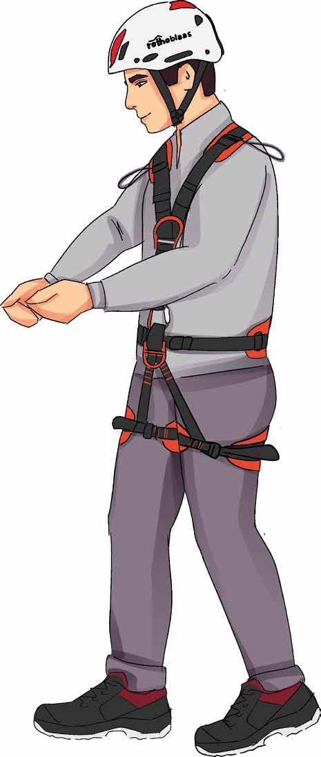
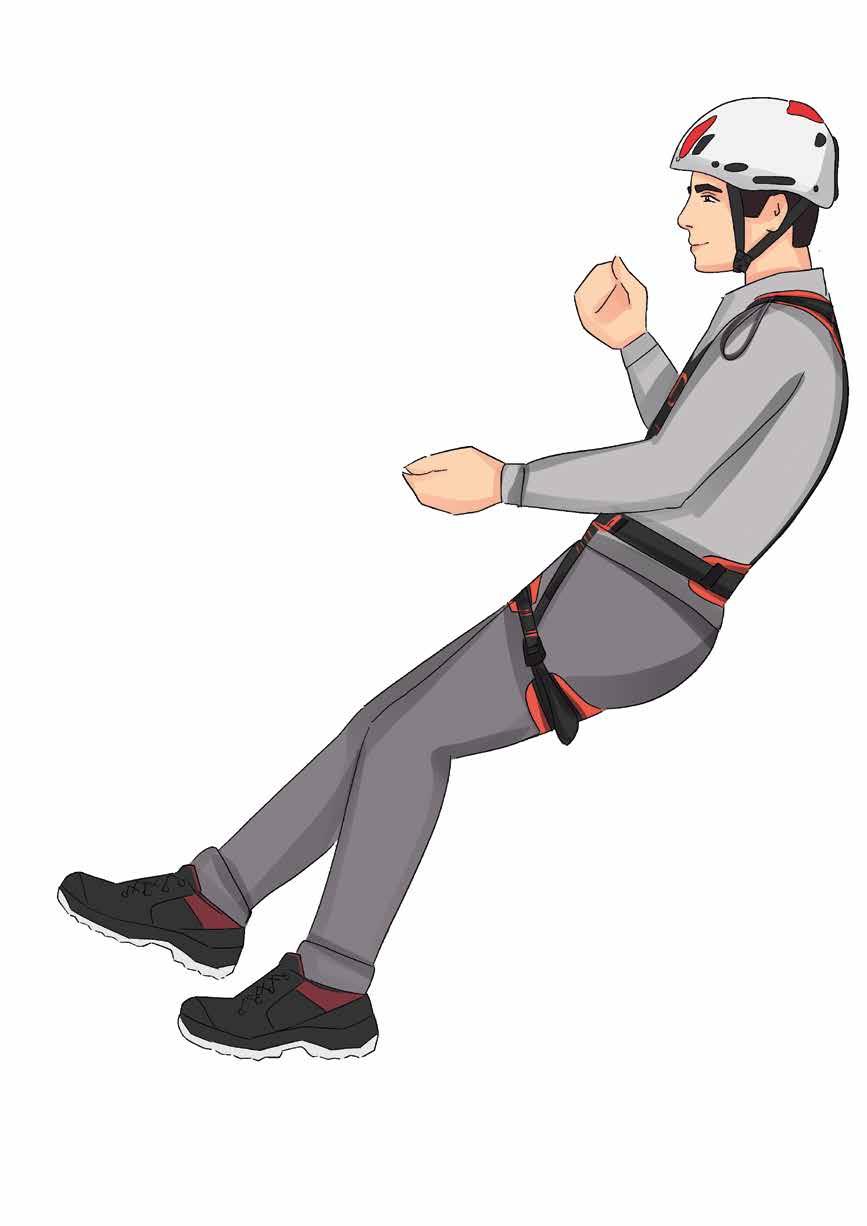
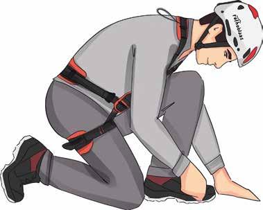
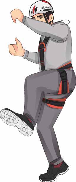
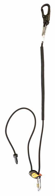
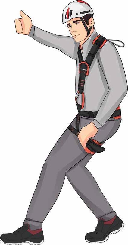
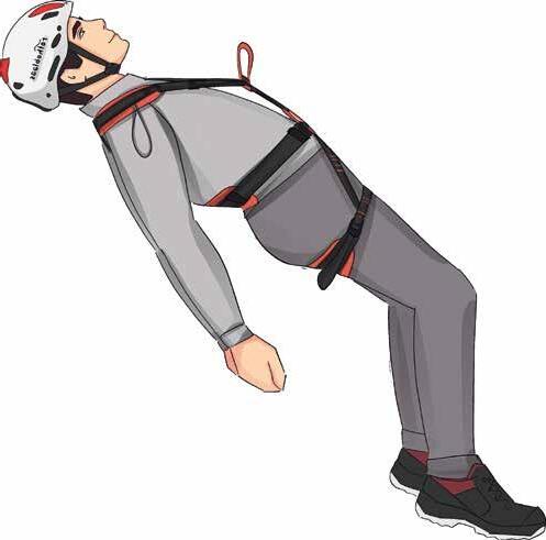
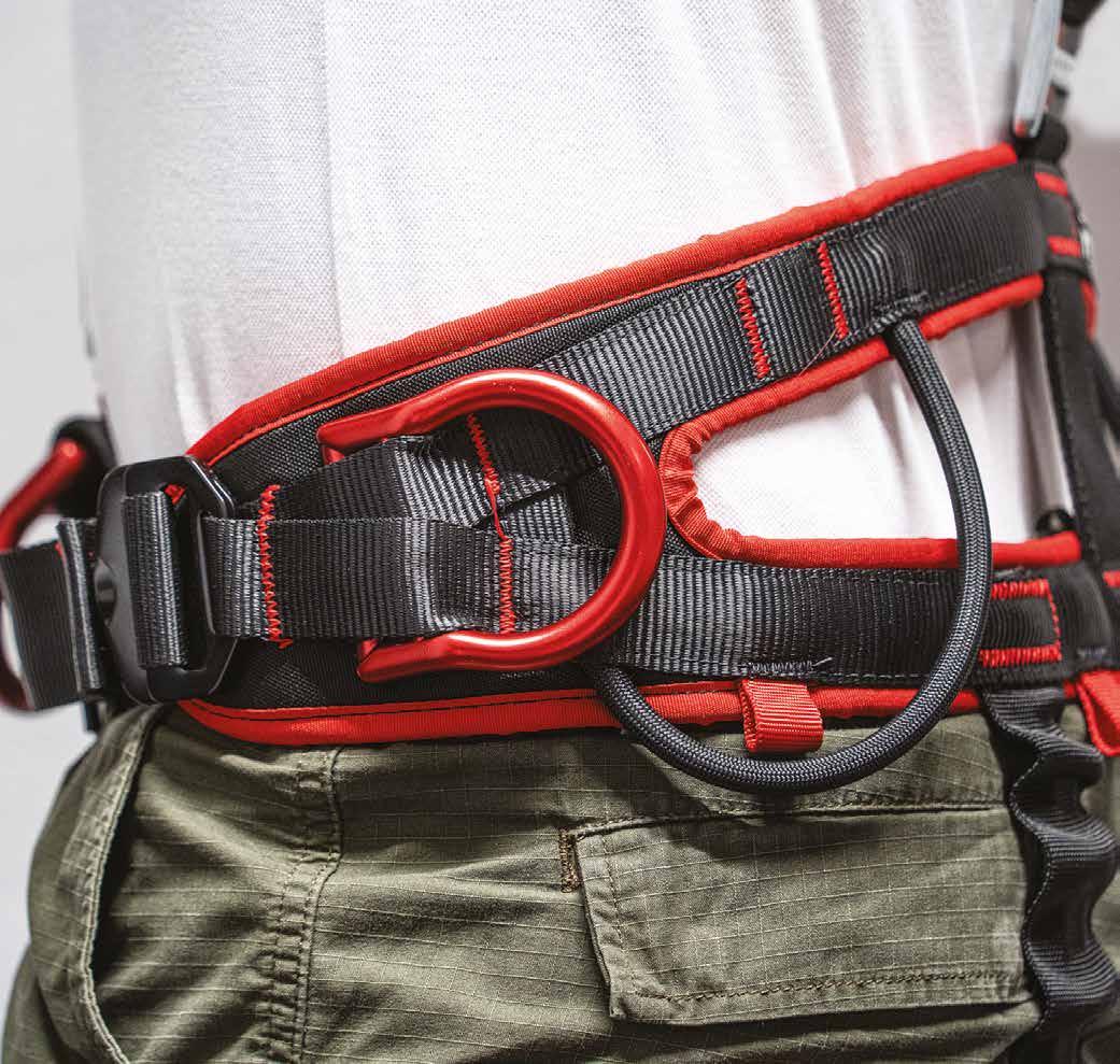
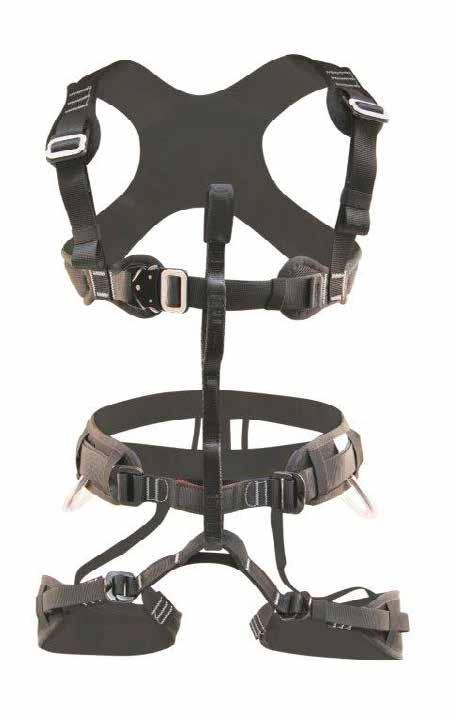
POSITIONING
Working technique that allows the operator to work under tension with its devices, hands free:
• in the case where the risk of falling into the void is null: positioning harness and positioning lanyard.
• if there is a risk of falling (uncovered roof, roof not protected by collective protection, steep slope, etc.): positioning and fall protection harness, positioning lanyard, fall arrest system.
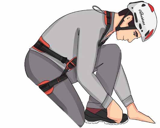
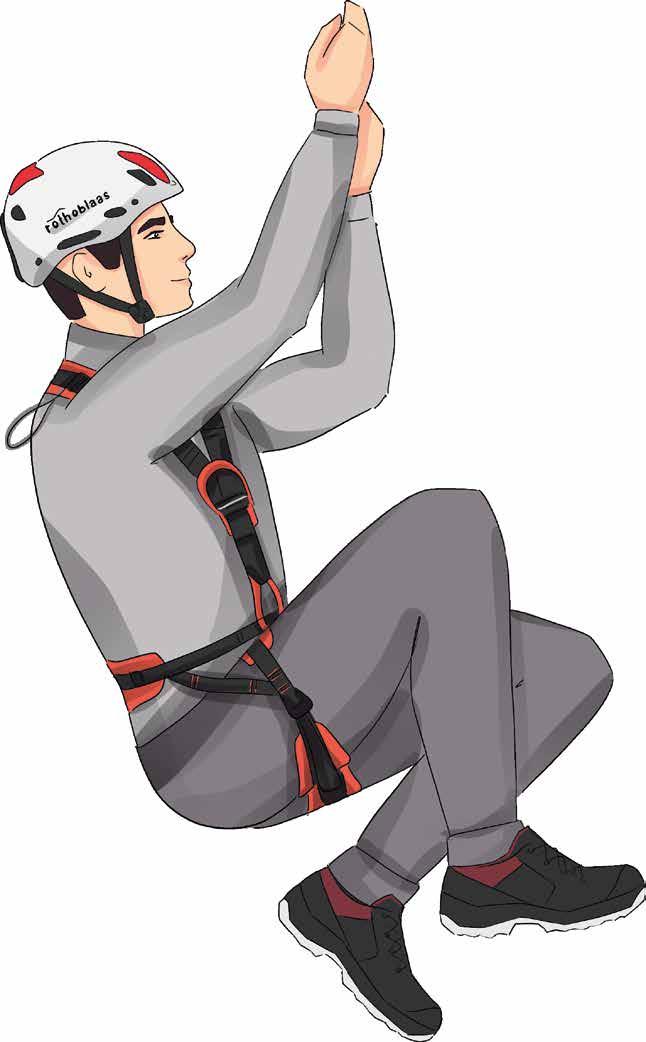
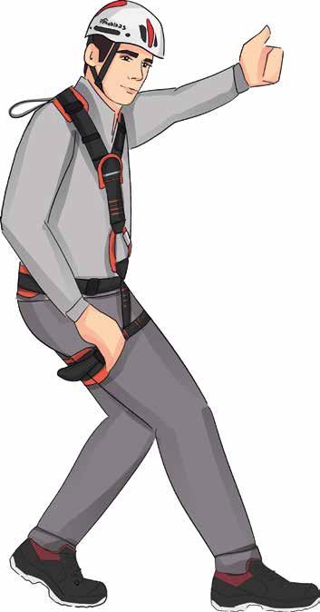
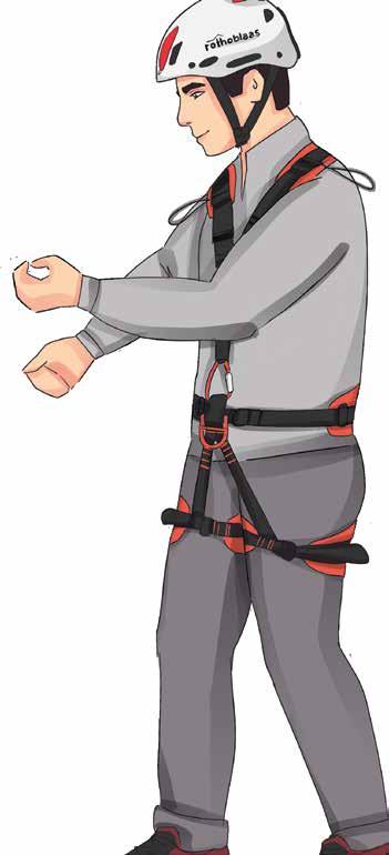
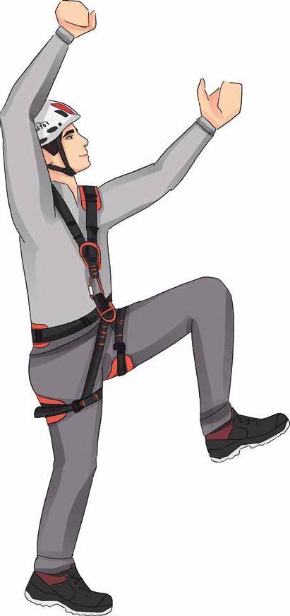
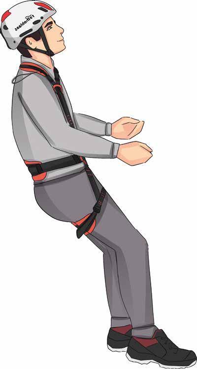
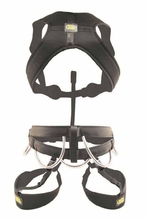
RESTRAINT
Work with restraint involve a system that limits worker movement to prevent them reaching areas in which a fall from height could occur. This system does not arrest a fall from height, but instead prevents it.
This system is generally preferable compared to working with a fall protection system.
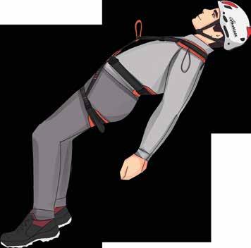
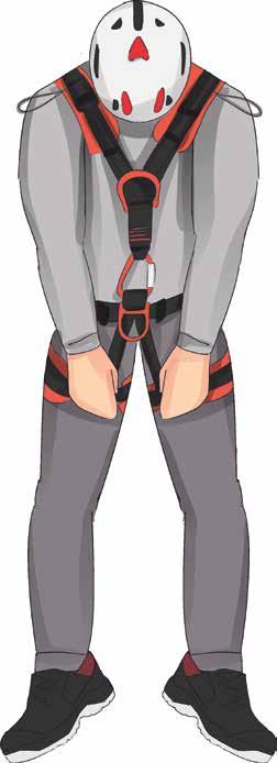
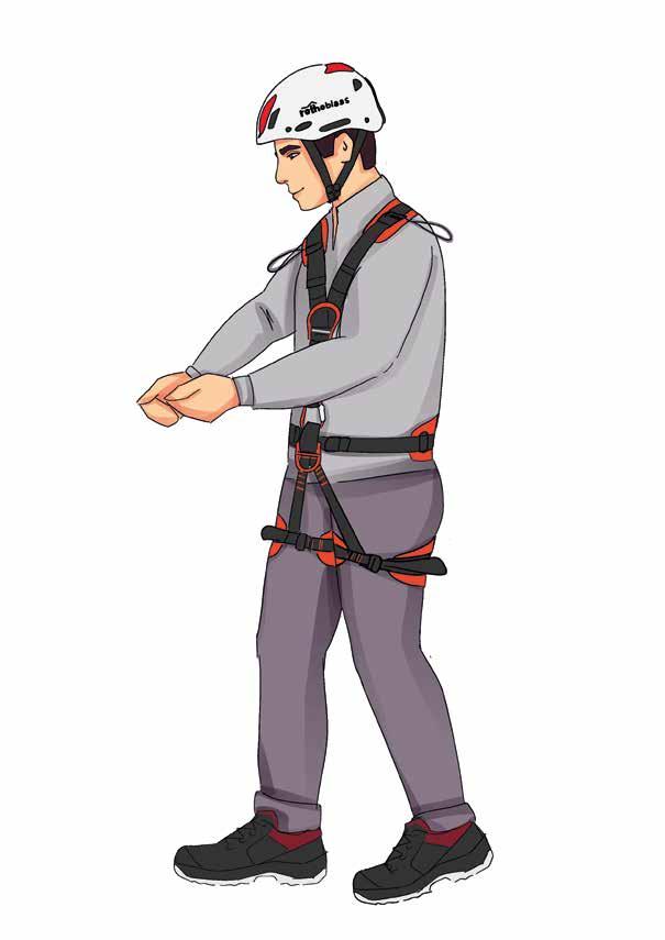
FALL PROTECTION
The fall arrest system has the purpose of:
• reducing the distance required to arrest a fall;
• absorbing the energy of the fall to limit the arresting force transmitted to the human body;
• keeping the injured in an appropriate position to limit the effects of inert suspension.
RISKS: PENDULUM EFFECT
The "pendulum effect" refers to a lateral movement that occurs after a fall when the anchor is not located vertically with respect to the worker. This situation can be dangerous, as it can cause the worker to collide with an obstacle located along the fall trajectory.
PRINCIPLES OF WORK AT HEIGHT
VERTICAL CLEARANCE
When working in fall protection, the VERTICAL CLEARANCE must be taken into account:
TA = LC + Lmax + HA + DSIC (+ f) [m]
TA vertical clearance
LC length of the rope from the fixed anchoring point to the roof to the anchoring point of the harness at the moment the rope begins to stop the fall
Lmax maximum extension of the energy absorber (maximum 1,75 m)
HA 1,50 m average height above the operator's feet from the sternal/ dorsal anchor point of the harness
DSIC safety distance (minimum 1 m)
f possible deformation of the system caused by a fall
FALL FACTOR
The FALL FACTOR expresses the degree of danger of a fall:
FC = H / L
FC fall factor
H height fallen during the fall
L length of the rope / connection device
The value obtained from the equation must be between 0 and 2, with 2 representing the maximum fall factor.
The lower the value of the fall factor, the less stress will be placed on the operator's body. On the other hand, a high fall factor can result in high decelerations that are difficult for a human body to withstand and cause serious injuries to the operator.
without energy absorber with energy absorber
FC0
STANDARDS
OVERVIEW OF REGULATIONS ON LIFELINES, RAILS AND ANCHOR POINTS
PATROL + SHIELD H-RAIL ON FLOOR
AOS01 + BLOCK
V-RAIL WING
VERTIGRIP
LIFE LINE SYSTEM LIFELINE AND RAIL SYSTEMS
LIFELINE
LIFELINE AND RAIL SYSTEMS
VERTICAL LIFELINE
VERTIGRIP
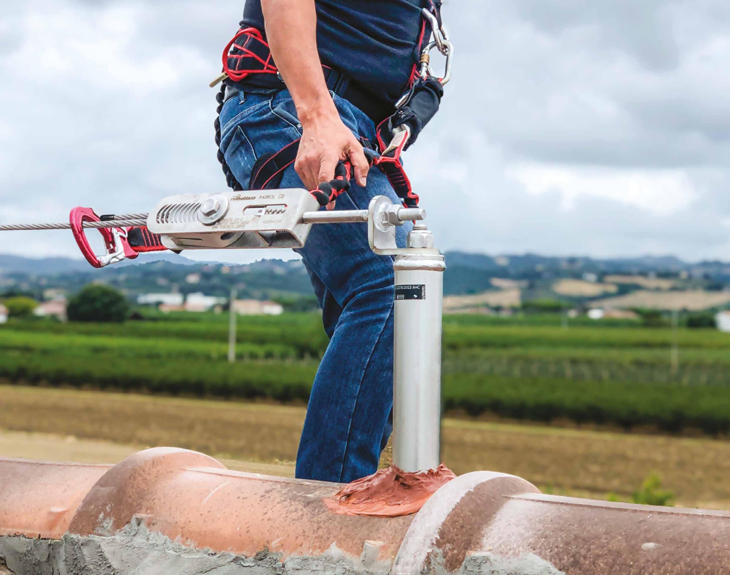
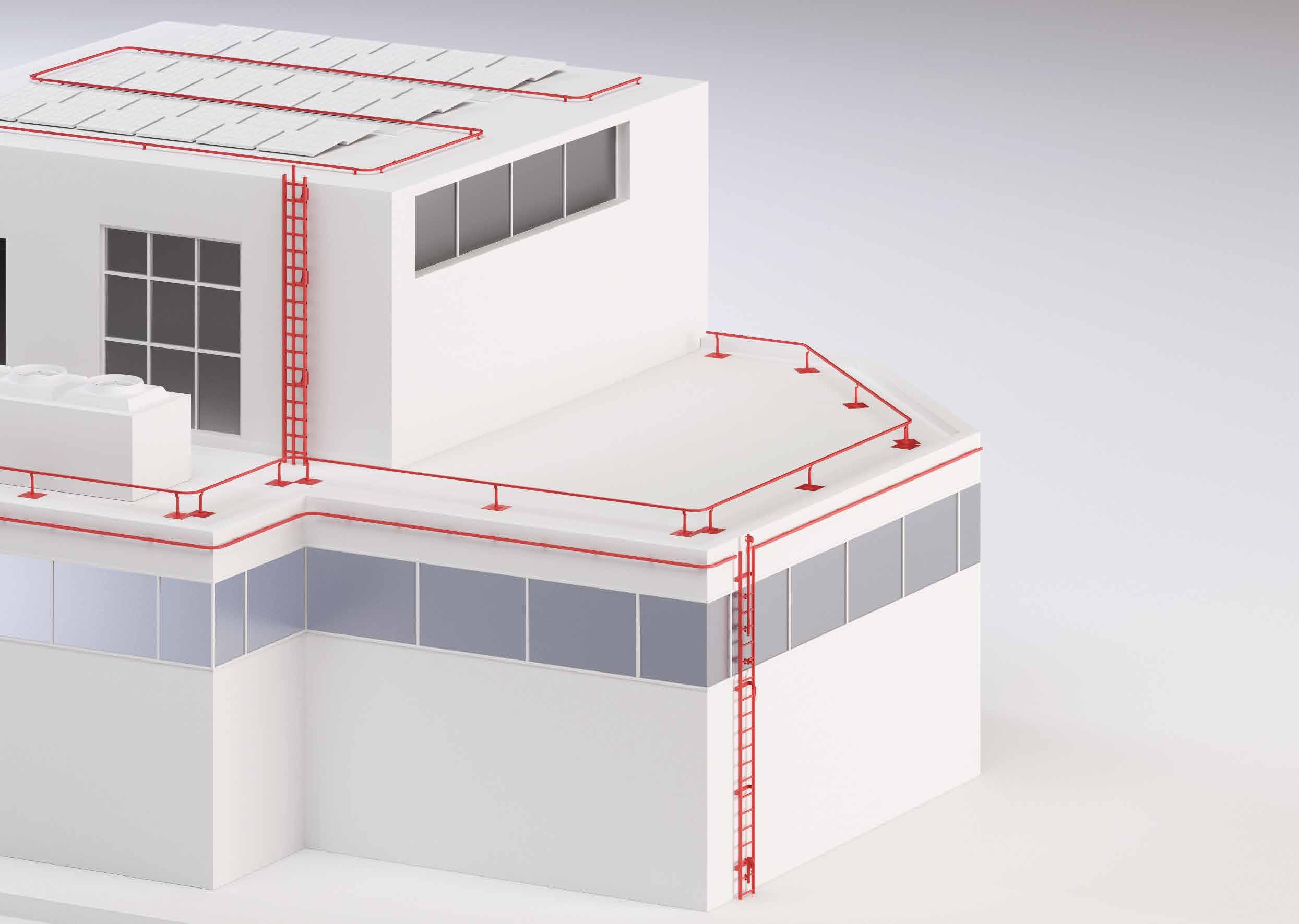
PATROL
HORIZONTAL LIFELINE
MODULAR, SIMPLE, SAFE SYSTEM.
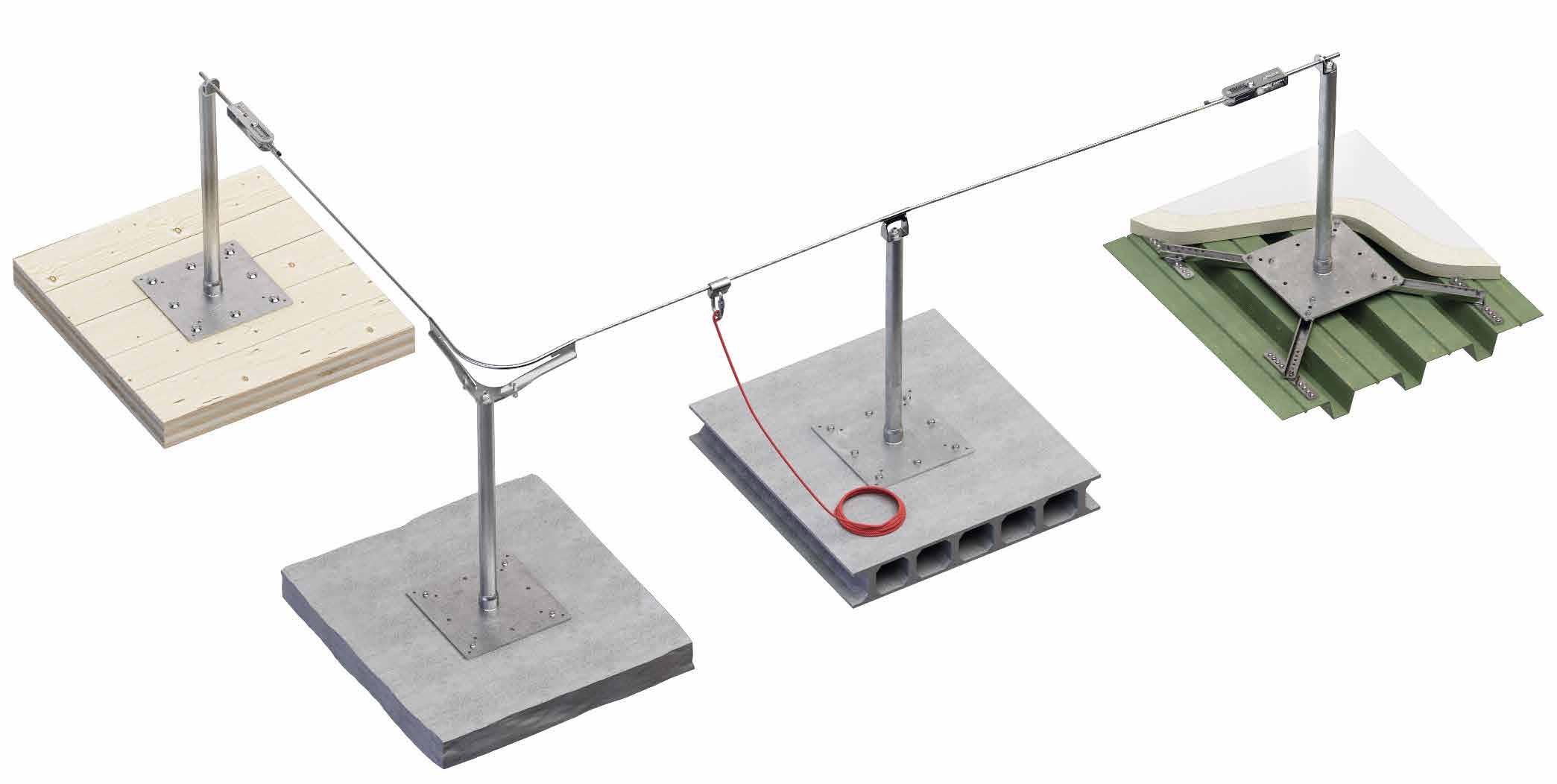
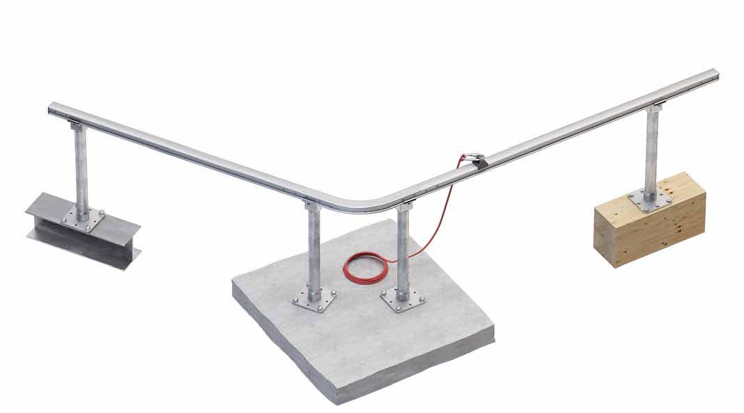
With PATROL LIFELINE SYSTEMS, horizontal, overhead or façade lifelines, both through and overhead, are child's play. Dedicated brackets allow you to quickly install the system on timber, metal or concrete substrates, and with the wide selection of specific accessories it is easy to meet all project requirements.
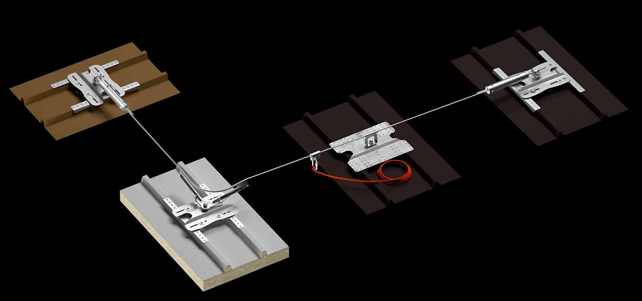
PATROL | overview
LIFILINE ON SUPPORT FOR TIMBER, CONCRETE AND STEEL ROOFS
LIFILINE ON STAINLESS STEEL SUPPORT FOR TIMBER, STEEL AND CONCRETE ROOFS
LIFILINE ON SUPPORT WITH INCREASED BOTTOM PLATE FOR TIMBER, STEEL AND CONCRETE ROOFS
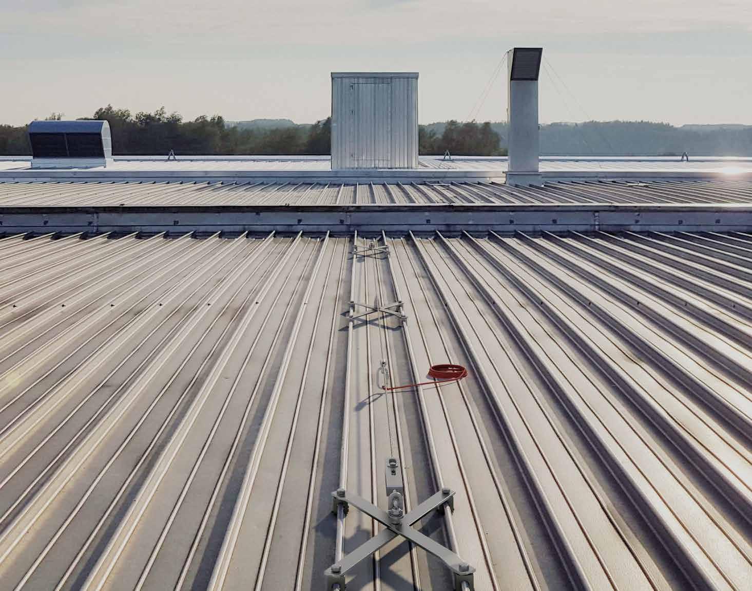
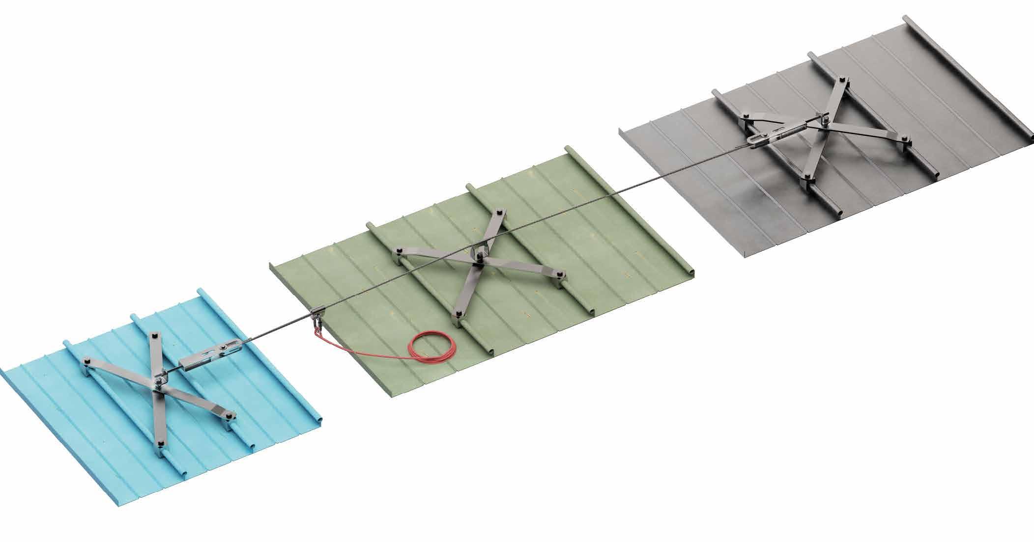
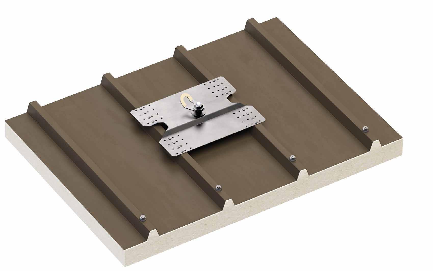
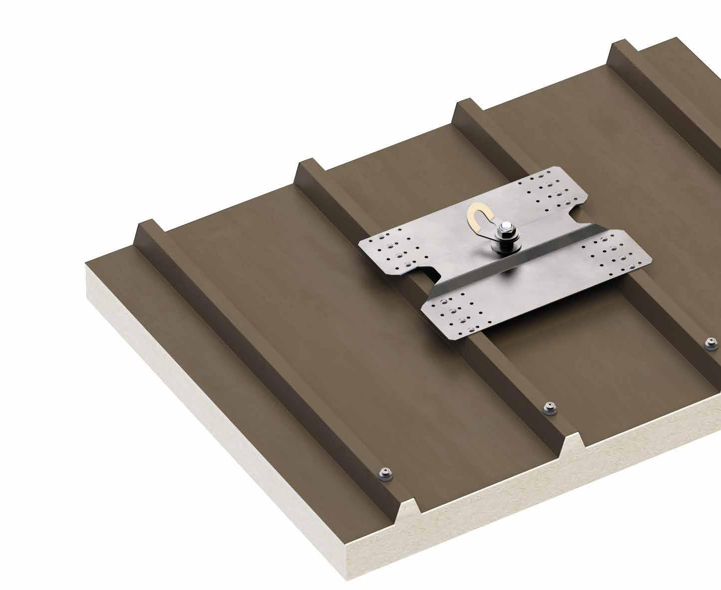
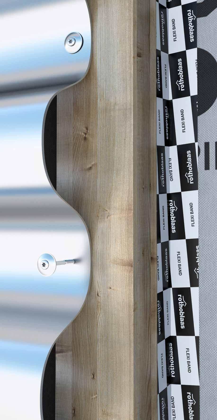
LIFELINE ON SUPPORT FOR TRAPEZOIDAL METAL ROOFS WITH AND WITHOUT INSULATION LAYER
PATROL | overview
PATROL + SIANK 4 | SIANKINT
LIFELINE ON SUPPORT FOR STANDING SEAM METAL ROOFS
PAGE 30
PATROL + SEAMO
LIFELINE ON SUPPORT FOR ROUND SEAM METAL ROOFS
LIFELINE ON SUPPORT ROOFS WITH FAUX TILES
PAGE 34
PATROL + TWIST
LIFELINE ON SUPPORT FOR CONTINUOUS ROOFS AND PVC/TPO AND OSB ROOFS
36 PAGE 32
PATROL + BLOCK
LIFELINE ON SUPPORT WITH BALLAST FOR FLAT ROOFS
PATROL + PATROLEND
LIFELINE WITH DIRECT FASTENING ON STEEL AND CONCRETE SUBSTRUCTURES
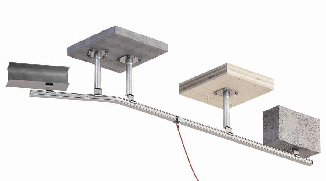
PATROL OVERHEAD
42 PAGE 40
AND CONCRETE
WALL-MOUNTED LIFELINE
AND CONCRETE PAGE 38
44
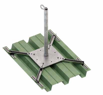
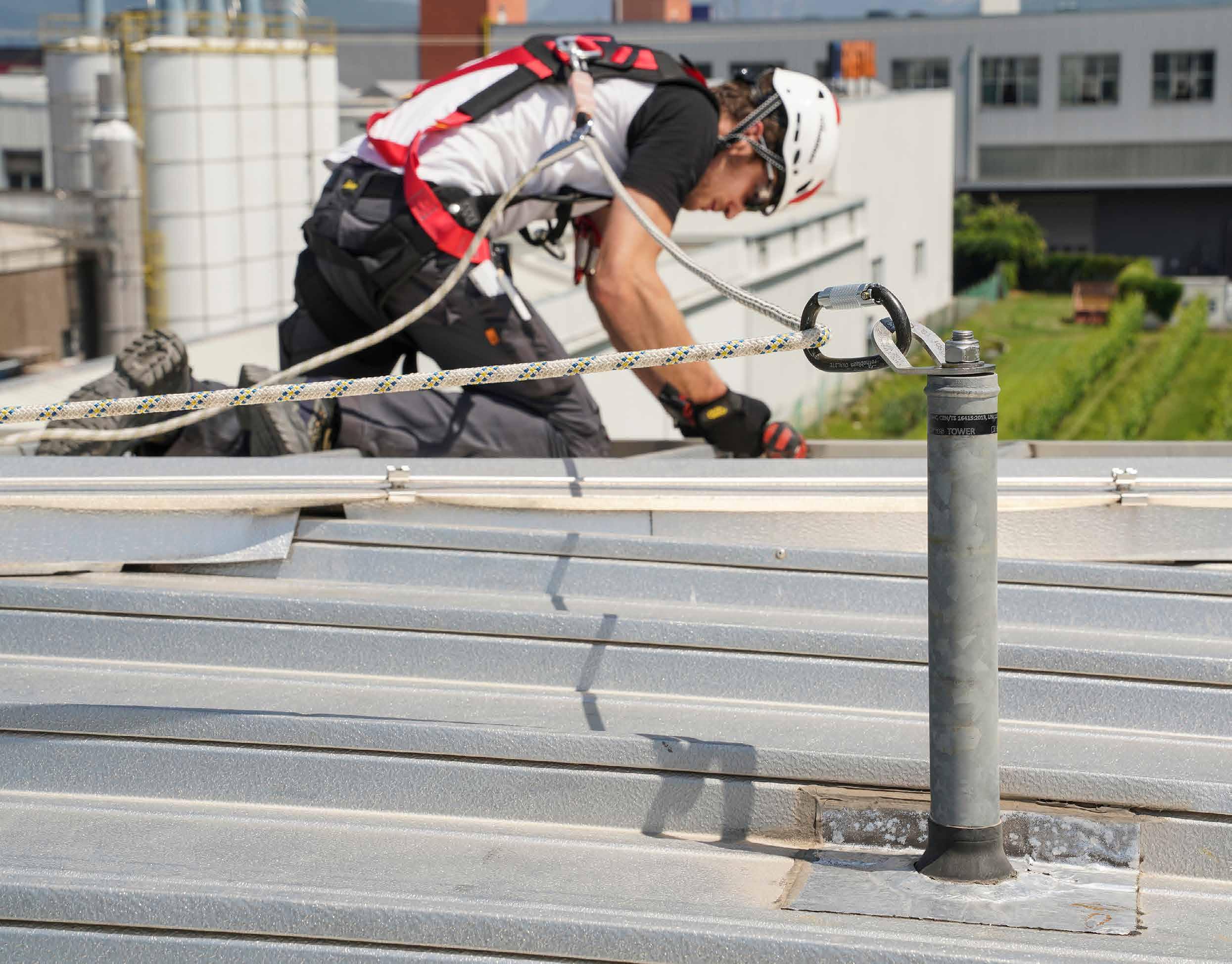
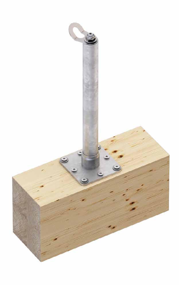
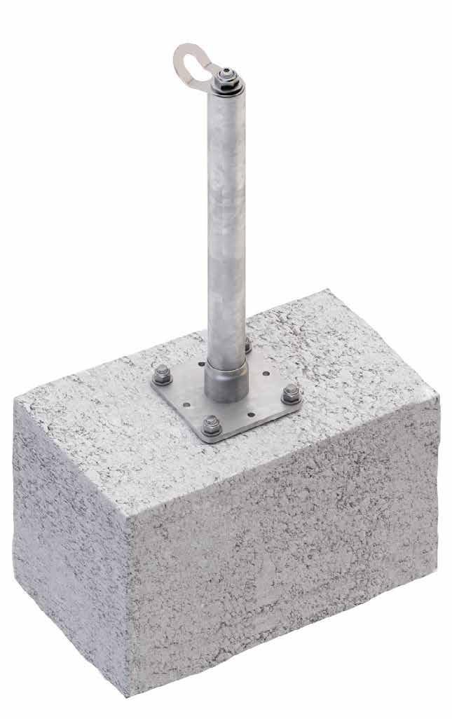
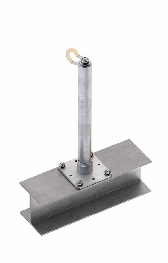
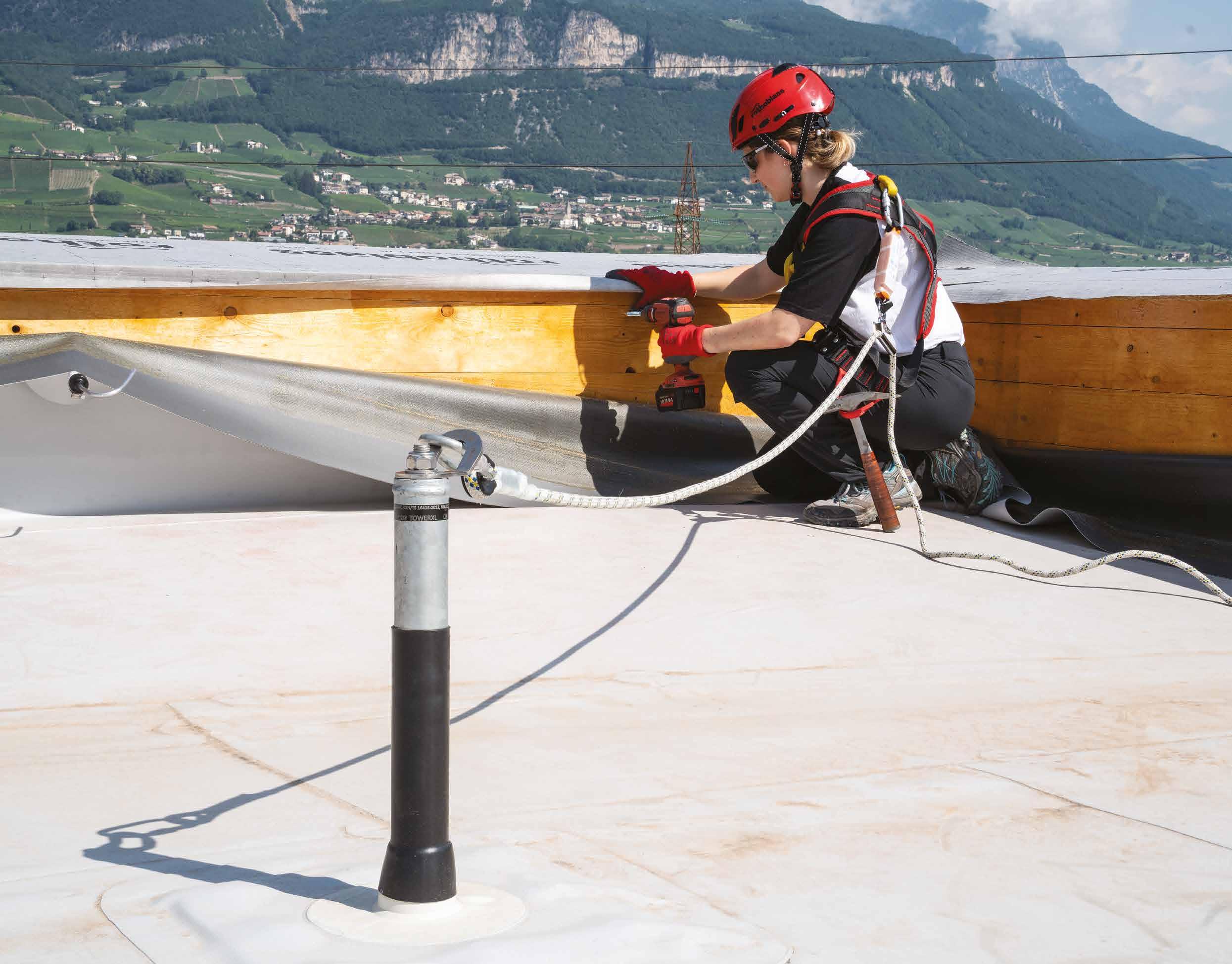
PATROL + TOWER
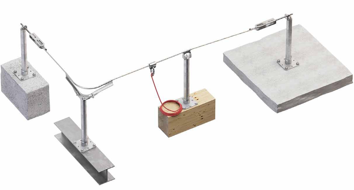
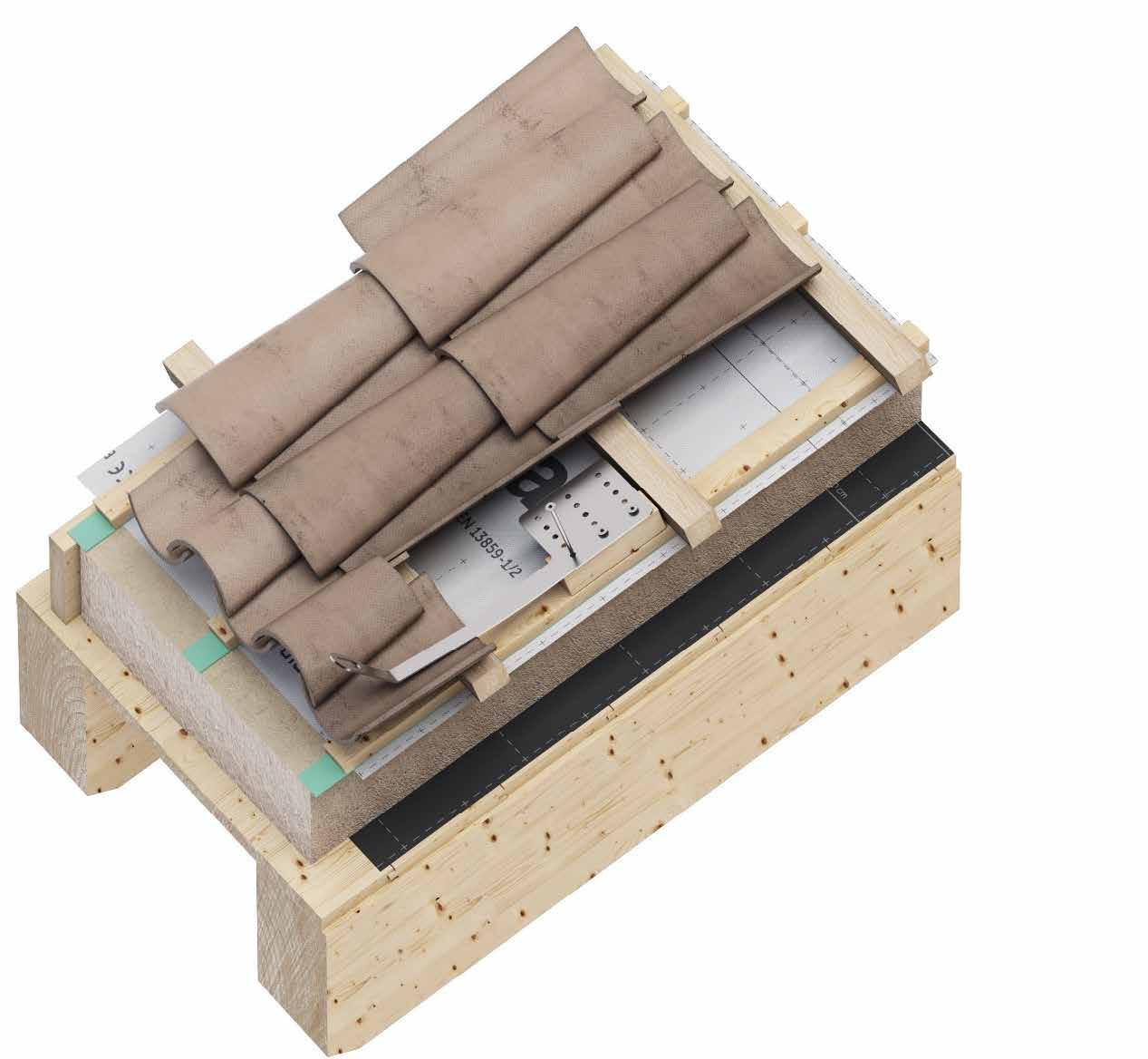
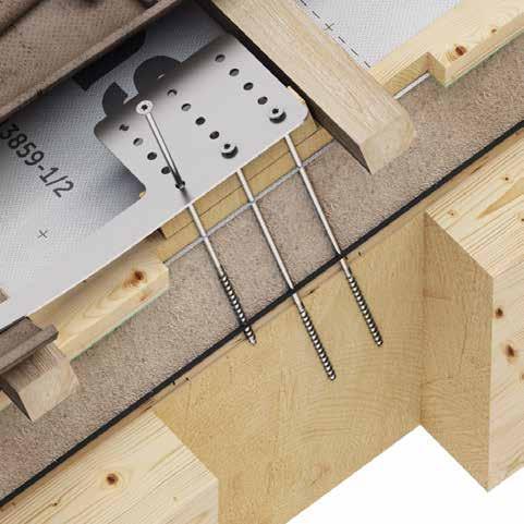
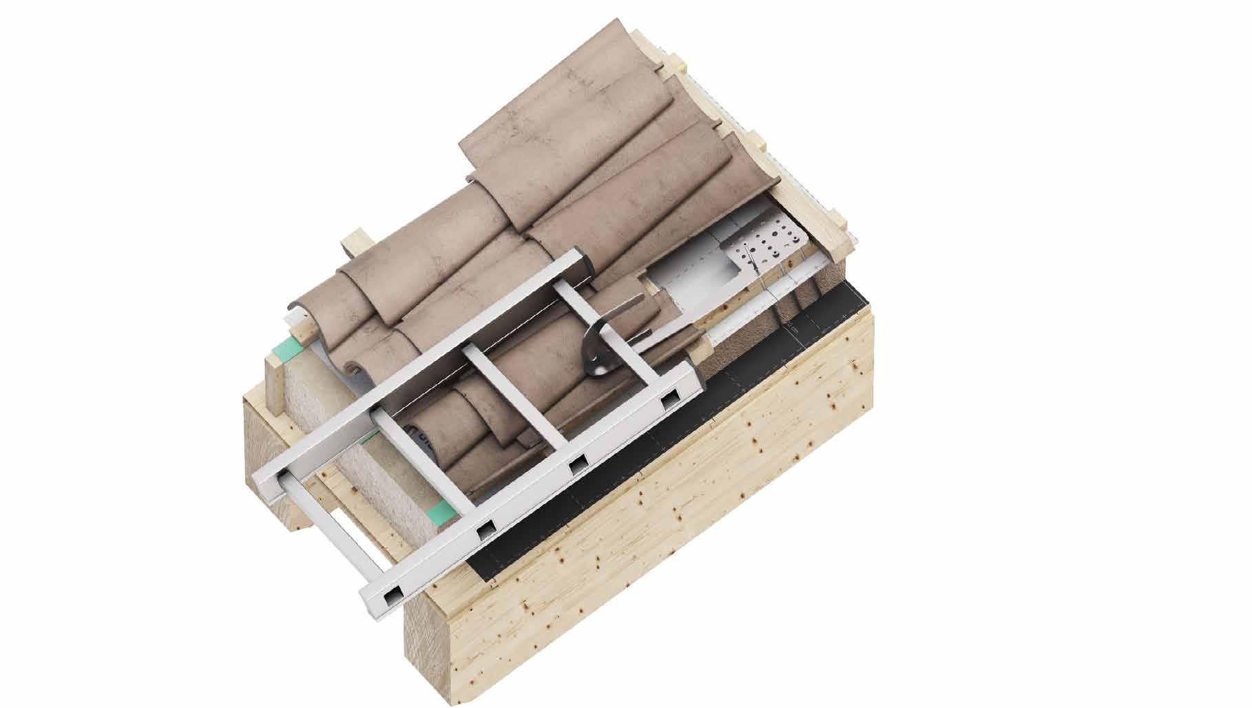
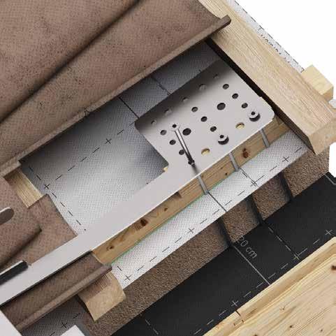
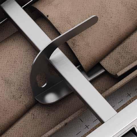
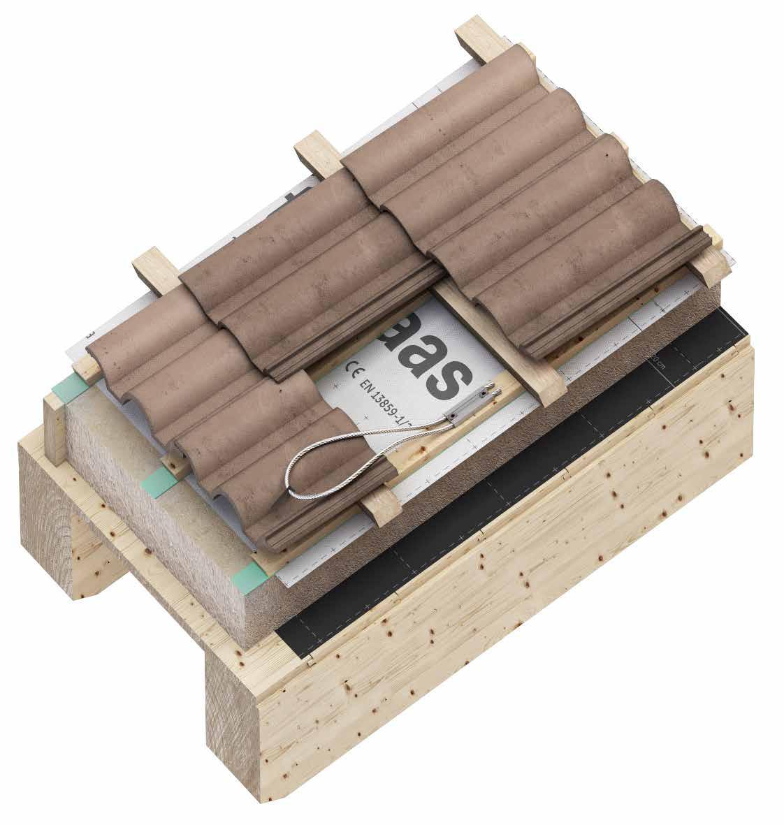
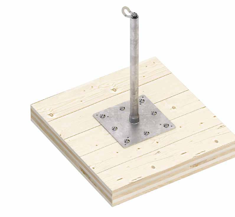
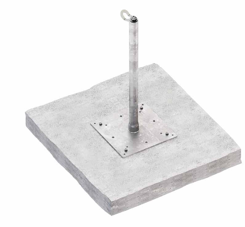
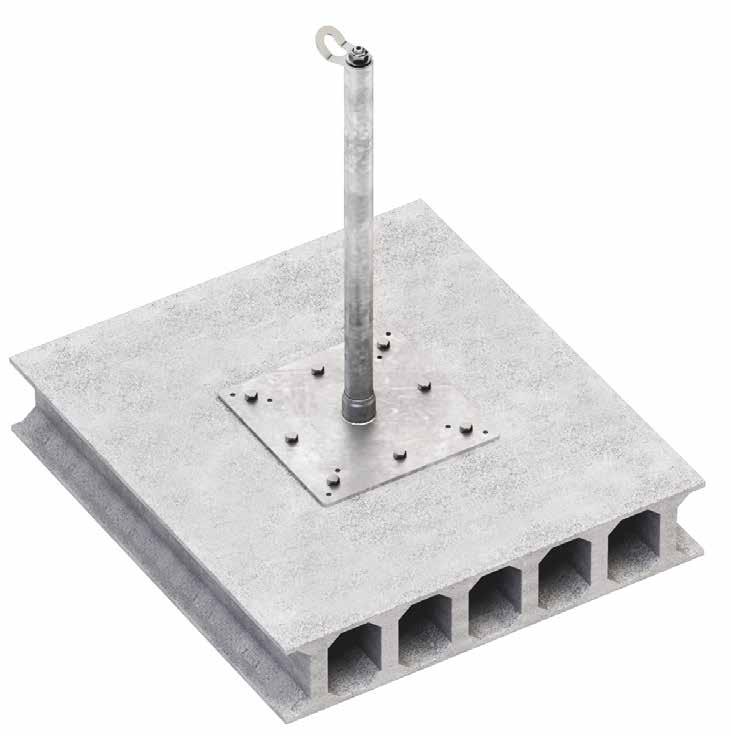
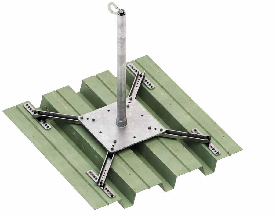
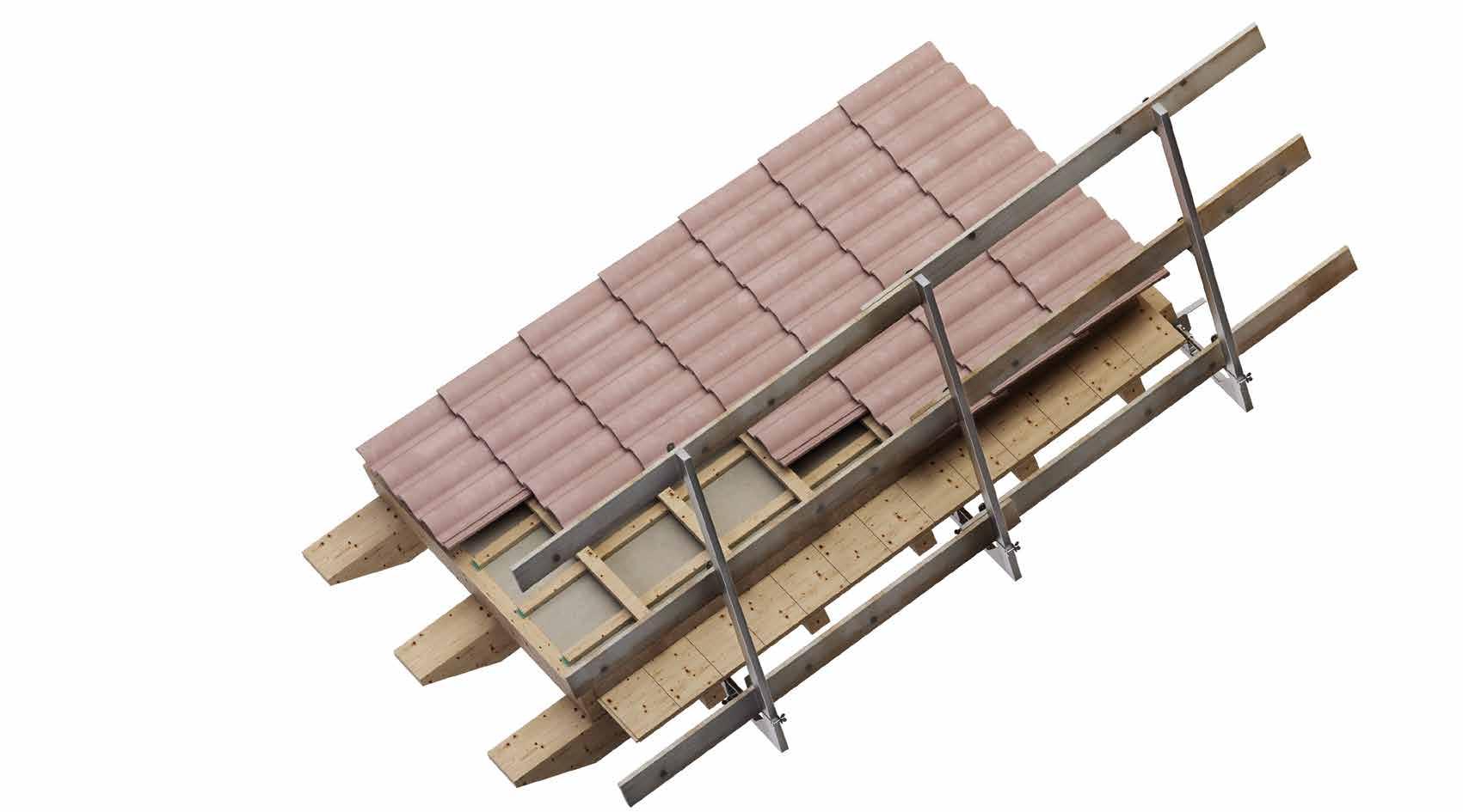
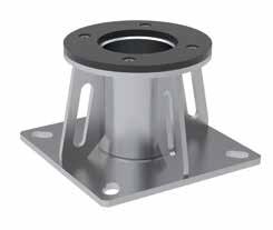
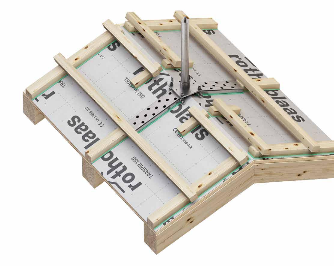
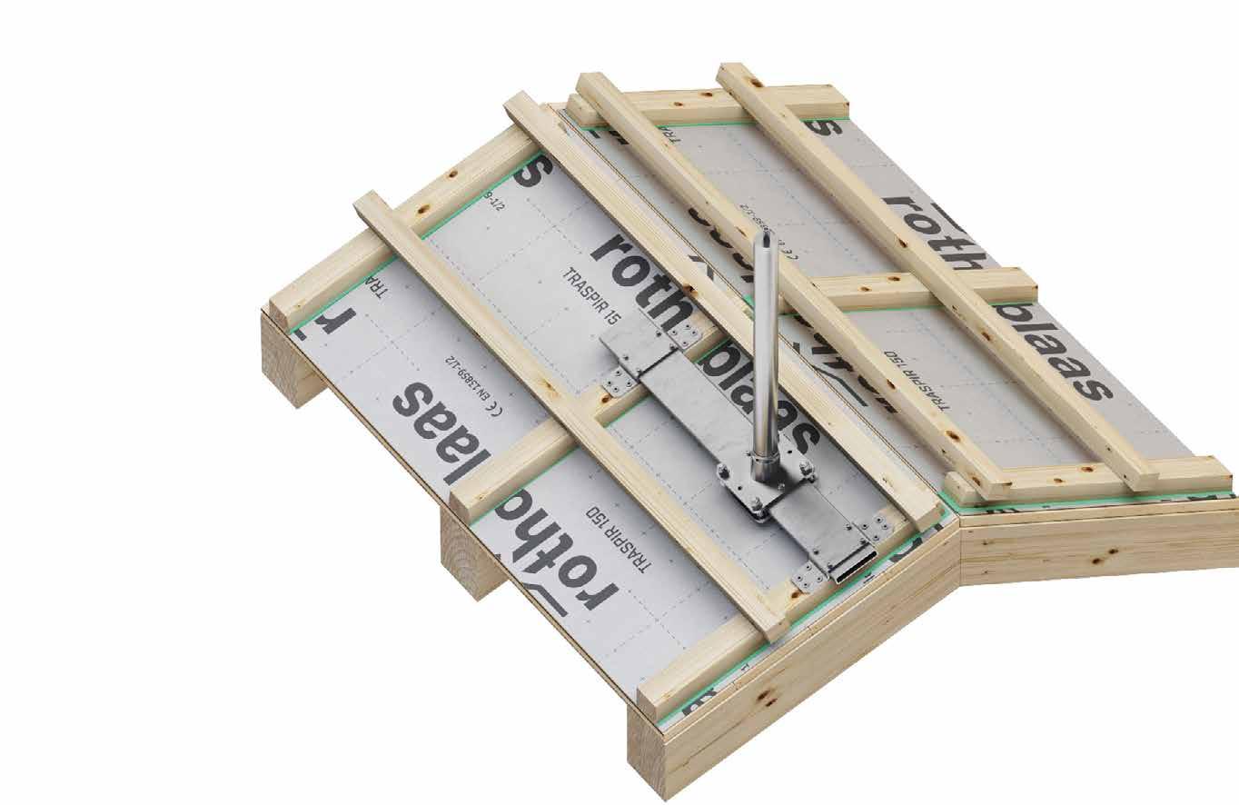
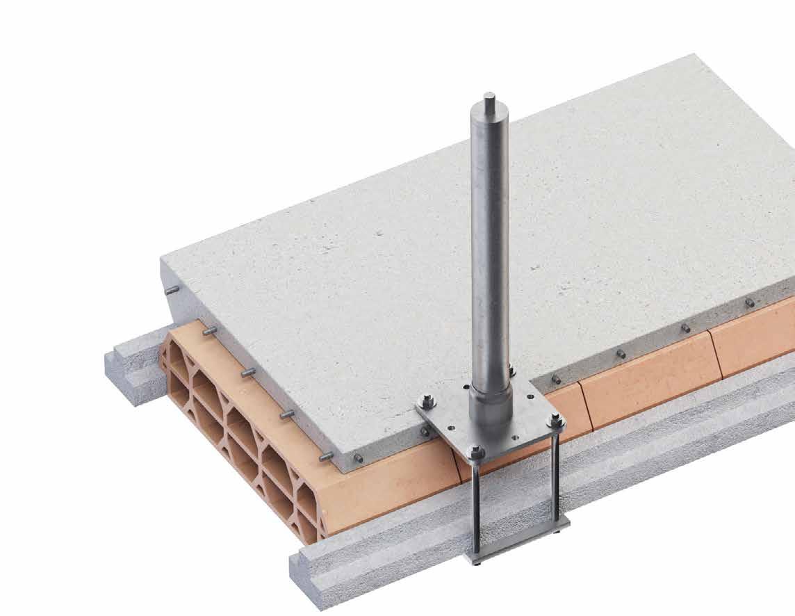
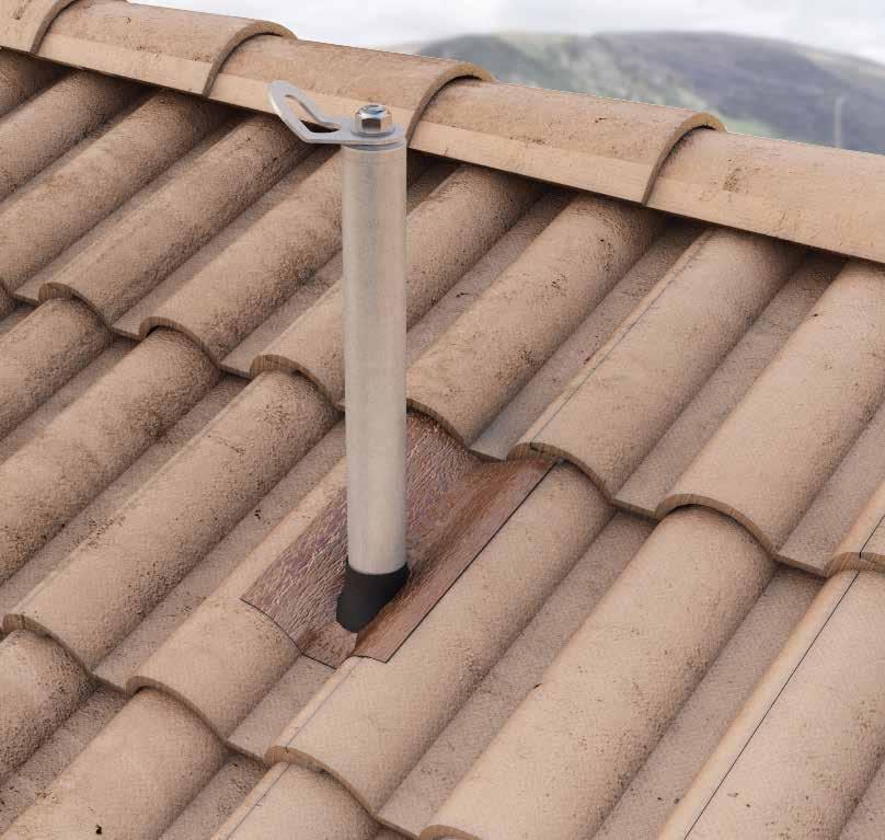
LIFELINE ON SUPPORT FOR TIMBER, CONCRETE AND STEEL ROOFS
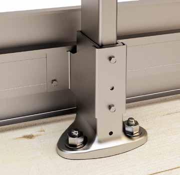
ADJUSTABLE
Support height between 300 and 600 mm to adapt to different thicknesses of roofing packages.
AESTHETICS
Small-sized cylindrical support to minimize the visual impact on the roofing.
SAFETY
Controlled deformation device to reduce the load on the fastening systems and structure.
Installation of a PATROL lifeline on TOWER supports on a structural glulam roof.
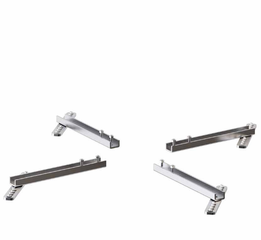
/ PATROLANG / PASANGBEND+ANGSUP
SLIDE 1 / SLIDE 2
PASINT / PATROLMED / PATROLINT
TECHNICAL DATA*
substructure minimum thickness fasteners GL24h
x 160 mm VGS Ø9VGS AB7
mm VGS Ø9VGS AB7 C20/25
mm AB1 Ø12 VGS AB7 M10 rod Ø12 AB7 M10 VIN VIN-FIX HYB-FIX M10 VIN SKR CE S235JR 6 mm EKS + ULS + MUT EKS M10 +ULS+MUT
* The values indicated are the result of experimental tests carried out under the supervision of third parties in accordance with the standard referred to. For a calculation report with minimum distances according to the relevant standard requirements, the substructure must be checked by a qualified engineer before installation.
TOWER | CODES AND DIMENSIONS
COMPLEMENTARY PRODUCTS
CODE description
adaptor for double layer ridge piece
fastening guide for rafter
PATROL + TOWER A2
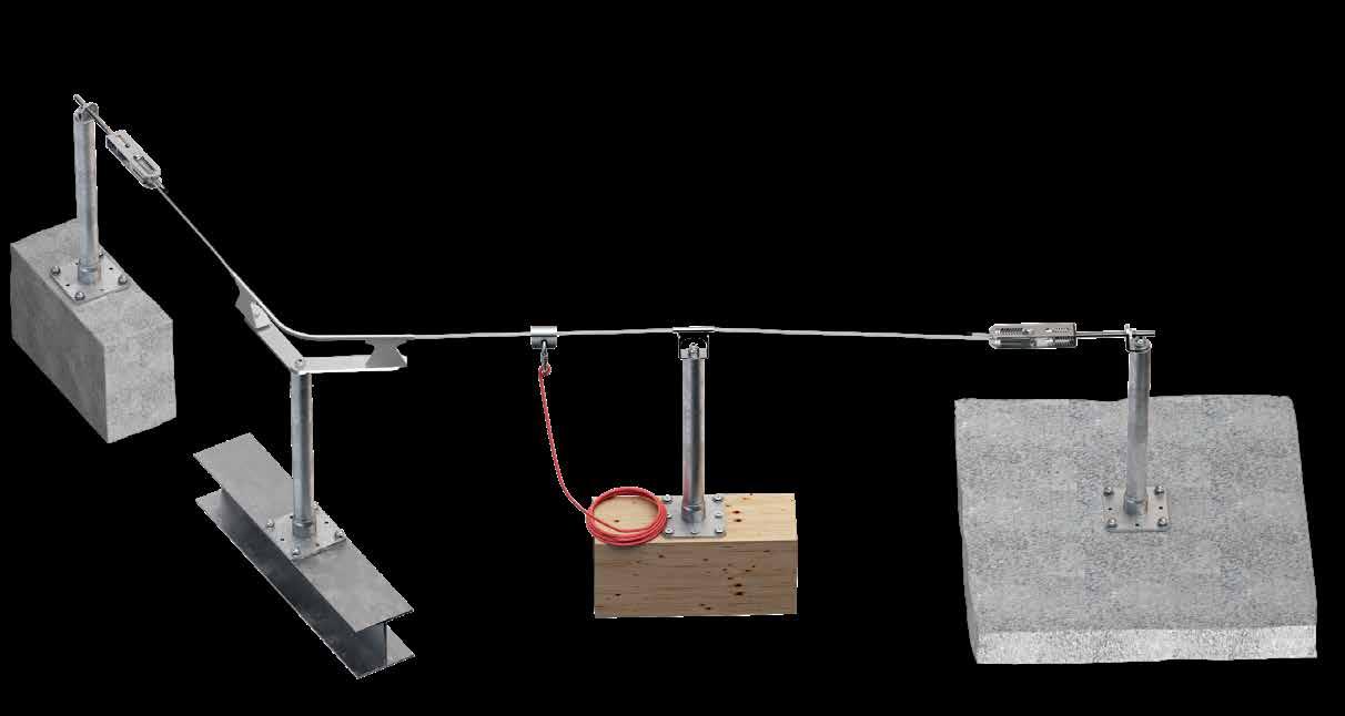
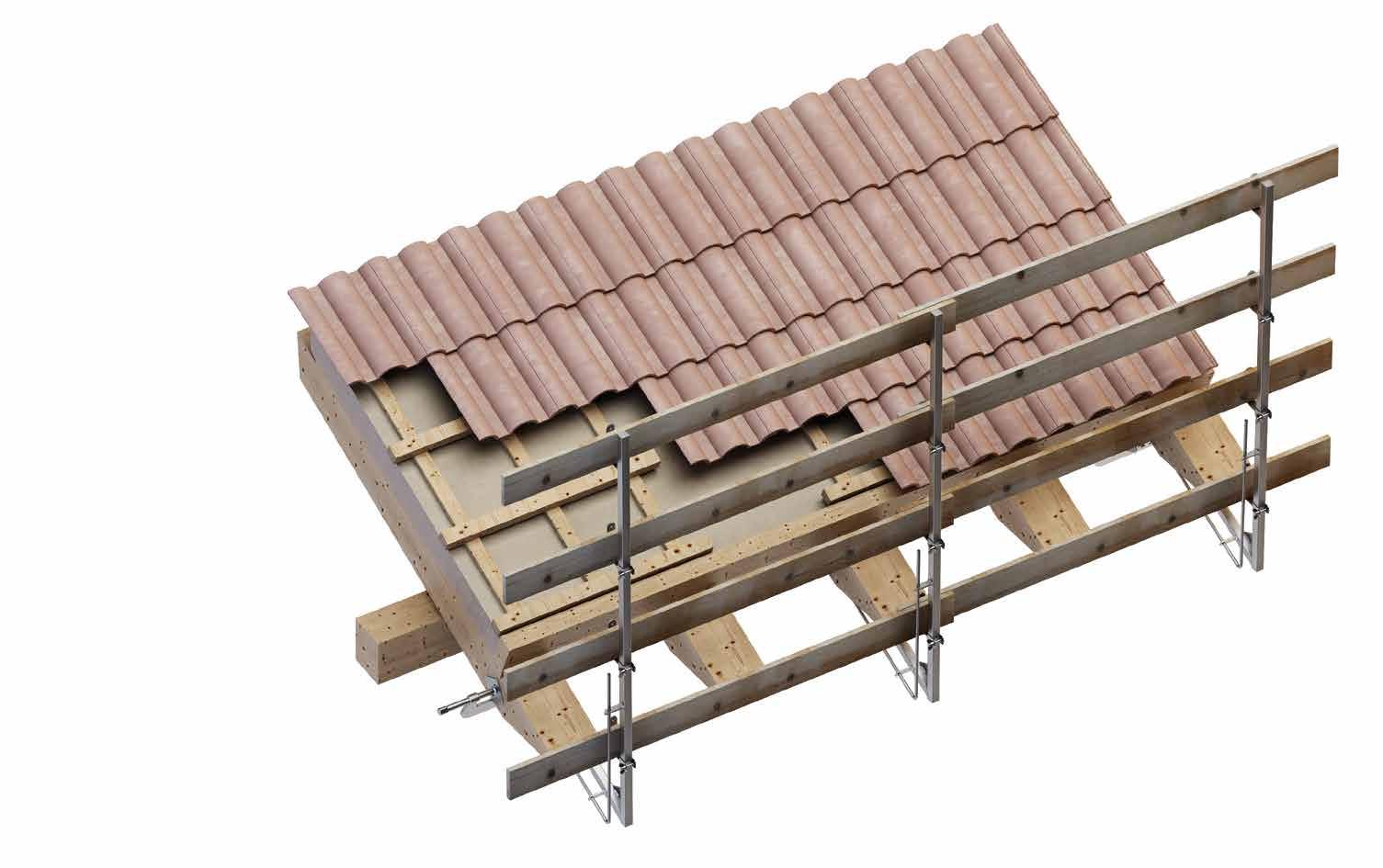
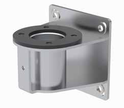
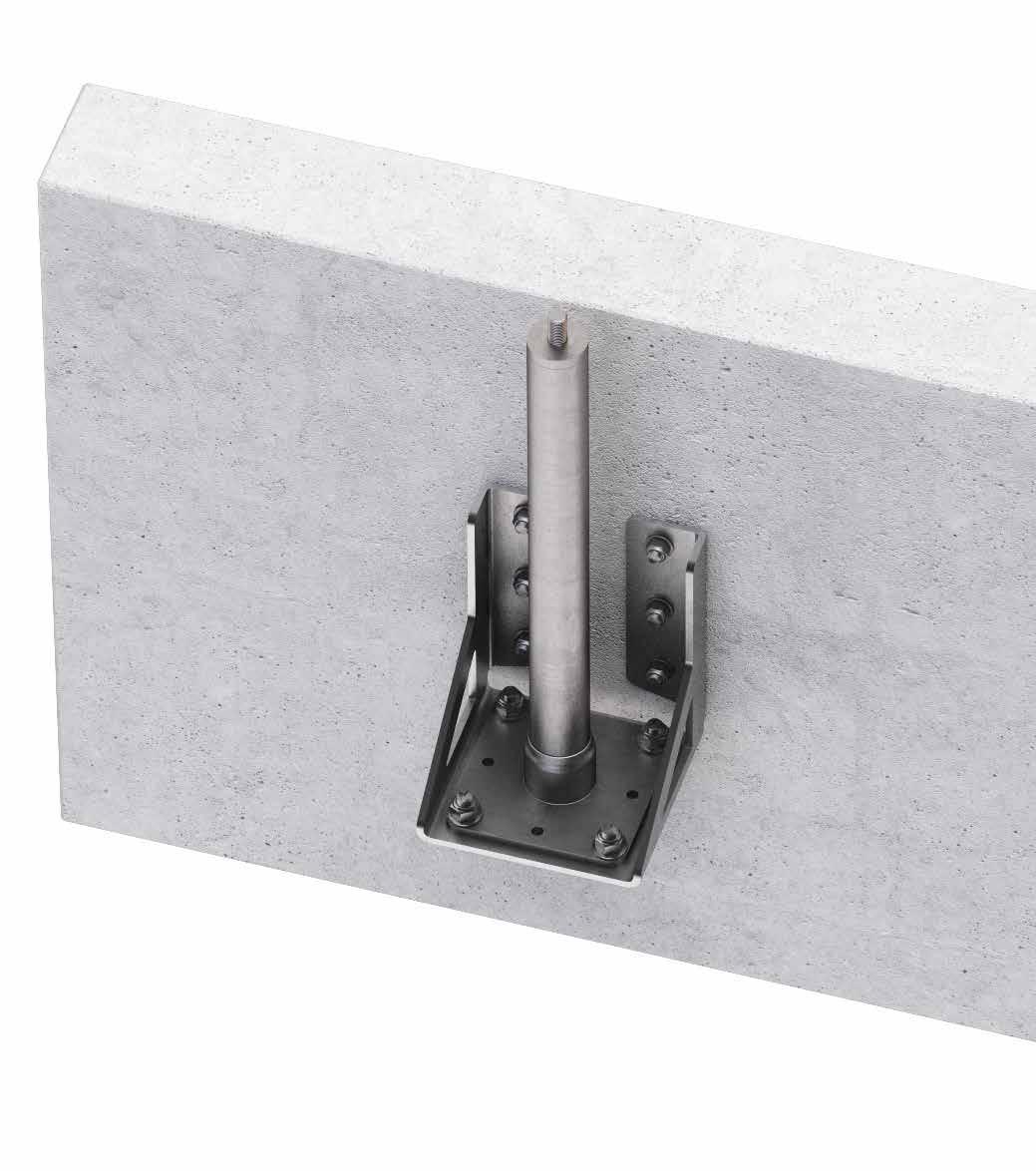
LIFELINE ON STAINLESS STEEL SUPPORT ON TIMBER, STEEL AND CONCRETE ROOFS
MATERIAL
A2 stainless steel support that guarantees excellent resistance and durability in corrosive environments.
AESTHETICS
Product that meets high aesthetic and functional requirements.
SAFETY
Controlled deformation device to reduce the load on the fastening systems and structure.
Installation of a PATROL lifeline with stainless steel TOWER A2 steel supports on a structure close to the edge.
4 PASANGBEND + ANGSUP / PATROLANG / PASANG
5 PASINT / PATROLMED / PATROLINT
6 SLIDE1 / SLIDE2
7 CABLE
TECHNICAL DATA*
substructure minimum thickness fasteners
GL24h 160 x 160 VGS Ø9VGS AB7
CLT 200 VGS Ø9VGS AB7
C20/25 140 AB1 Ø12 VGS AB7 M10 rod Ø12 AB7 M10 VINVIN-FIX HYB-FIX M10 VIN SKR CE
S235JR 6 EKS + ULS + MUT EKS M10 +ULS+MUT
* The values indicated are the result of experimental tests carried out under the supervision of third parties in accordance with the standard referred to. For a calculation report with minimum distances according to the relevant standard requirements, the substructure must be checked by a qualified engineer before installation.
TOWER A2 | CODES AND DIMENSIONS
COMPLEMENTARY PRODUCTS
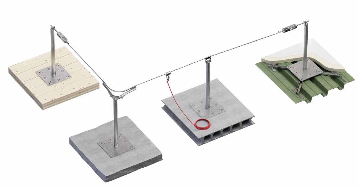
PATROL + TOWER XL
LIFELINE ON SUPPORT WITH INCREASED BOTTOM PLATE FOR TIMBER, STEEL AND CONCRETE ROOFS
VERSATILE
It can be mounted on various types of structure with tested fastenings.
ADJUSTABLE
Support height between 300 and 800 mm to adapt to different thicknesses of roofing packages.
SAFE
The enlarged bottom plate makes it possible to distribute the actions arising from the anchoring devices over a larger area.
Installation of a PATROL lifeline with TOWER XL supports on a flat roof with CLT structure and waterproofed with a synthetic covering.
n. CODE 1 TOWERXL 2 PATROLTERM / PATROLTERML 3 SPEAR
4 PASANG / PATROLANG / PASANGBEND + ANGSUP
5 SLIDE1 / SLIDE2
6 PASINT / PATROLMED / PATROLINT
7 CABLE
substructure
C20/25 110 mm AB7 Ø10 VGS AB7 M10 rod Ø10 AB7 M10 VINVIN-FIX M10 VIN SKR CE SKR CE Ø10 VIN SKR CE BEFTOWERXL
C45/55 30 mm BEFTOWERXL1 SKR CE BEFTOWERXL MTS 0,75 mm MTS A2 AISI 304 BEFTOWERXL MTS
* The values indicated are the result of experimental tests carried out under the supervision of third parties in accordance with the standard referred to. For a calculation report with minimum distances according to the relevant standard requirements, the substructure must be checked by a qualified engineer before installation.
TOWER XL | CODES AND DIMENSIONS
TECHNICAL DATA* COMPLEMENTARY
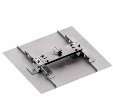
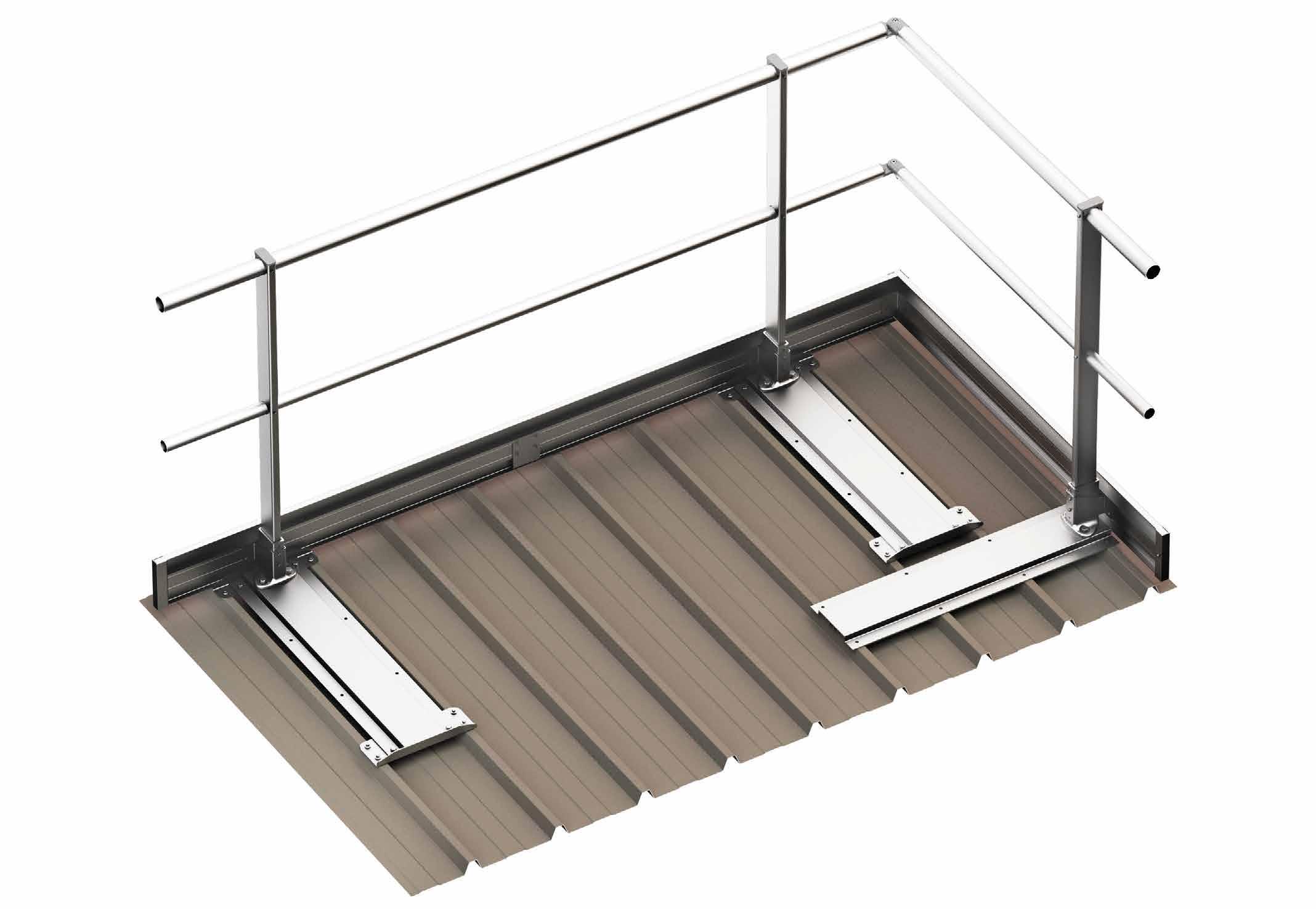
PATROL + SHIELD | SHIELD 2
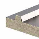
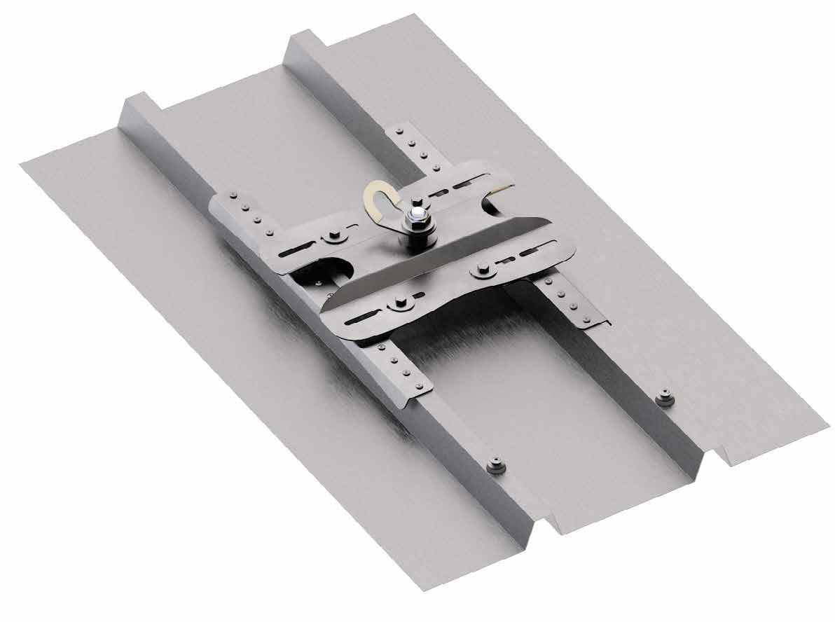
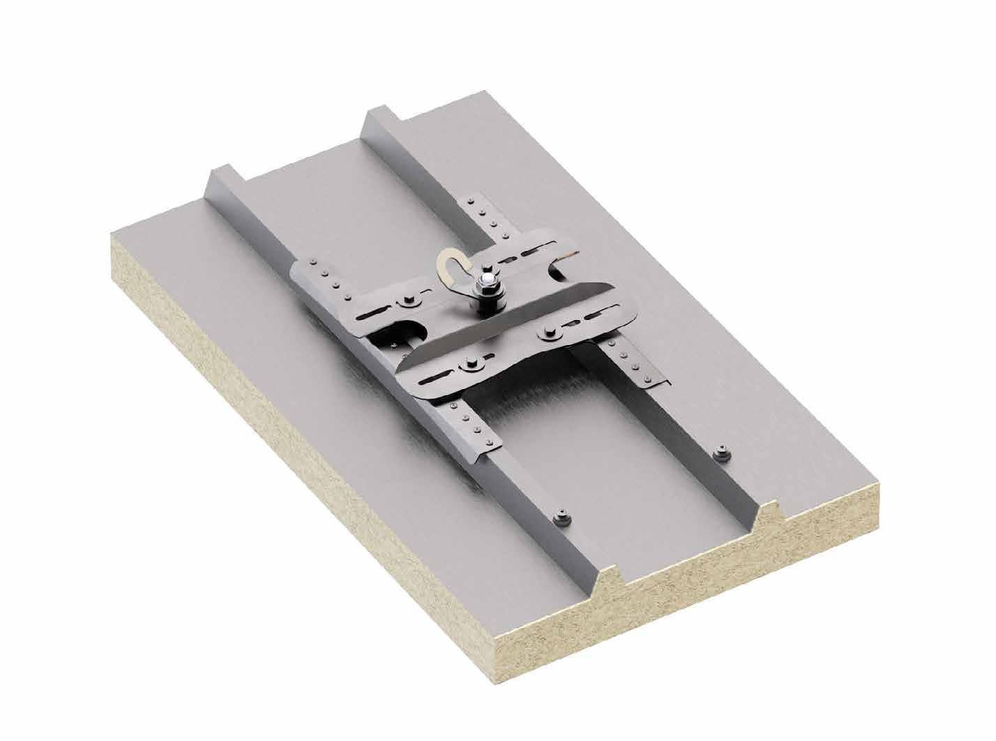
LIFELINE ON SUPPORT FOR TRAPEZOIDAL METAL ROOFS WITH AND WITHOUT INSULATION LAYER
COMPLETE
The package includes fasteners and cellular rubber seals, to ensure waterproofing.
APPLICATION
Used on all trapezoidal metal roofs with and without insulation layer with spacing between frets of up to 420 mm.
USE
SHIELD for use as a start, end or corner lifeline; SHIELD 2 for use as a straight intermediate point.
Installation of a PATROL lifeline with SHIELD supports on a steel sandwich panel roof.
PASANG / PATROLANG / PASANGBEND + ANGSUP
PASINT / PATROLMED / PATROLINT
SLIDE1 / SLIDE2
CABLE
TECHNICAL DATA*
substructure minimum thickness fastening systems included
Fe 0,5 mm
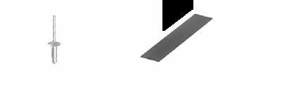
SHIELD: rivet 6,3 x 20,2 mm with EPDM washer (x 32)
SHIELD2: rivet 6,3 x 20,2 mm with EPDM washer (x 16) Fe 0,5 mm
mm Al
SHIELD | CODES AND DIMENSIONS
SHIELD 2 | CODES AND DIMENSIONS
* The values indicated are the result of experimental tests carried out under the supervision of third parties in accordance with the standard referred to. For a calculation report with minimum distances according to the relevant standard requirements, the substructure must be checked by a qualified engineer before installation. COMPLEMENTARY PRODUCTS
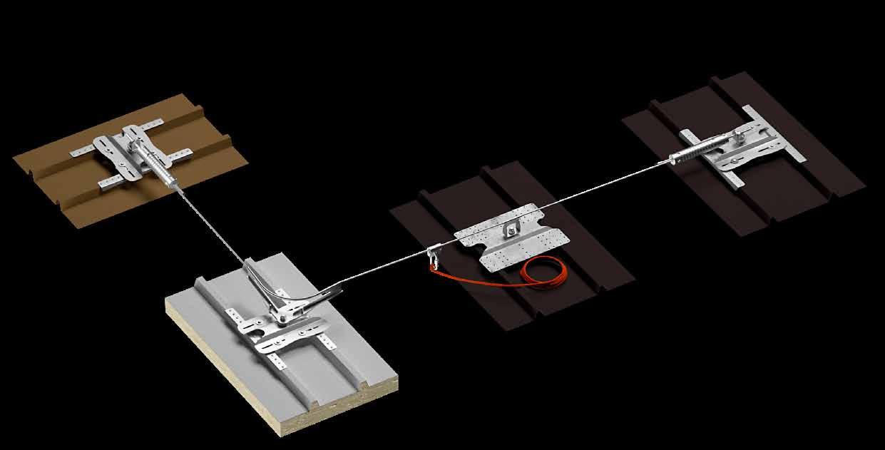
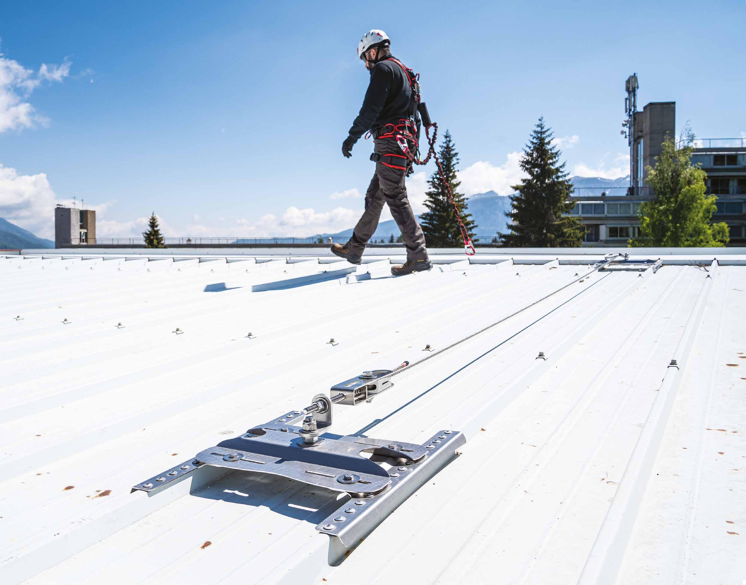
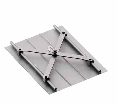
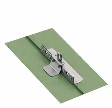
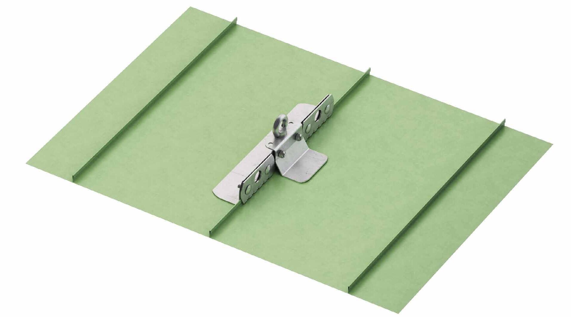
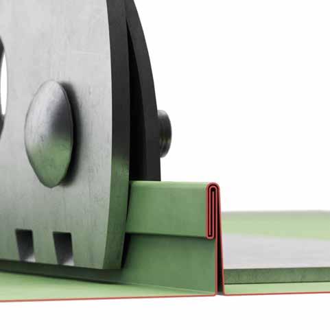
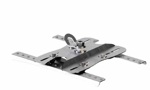
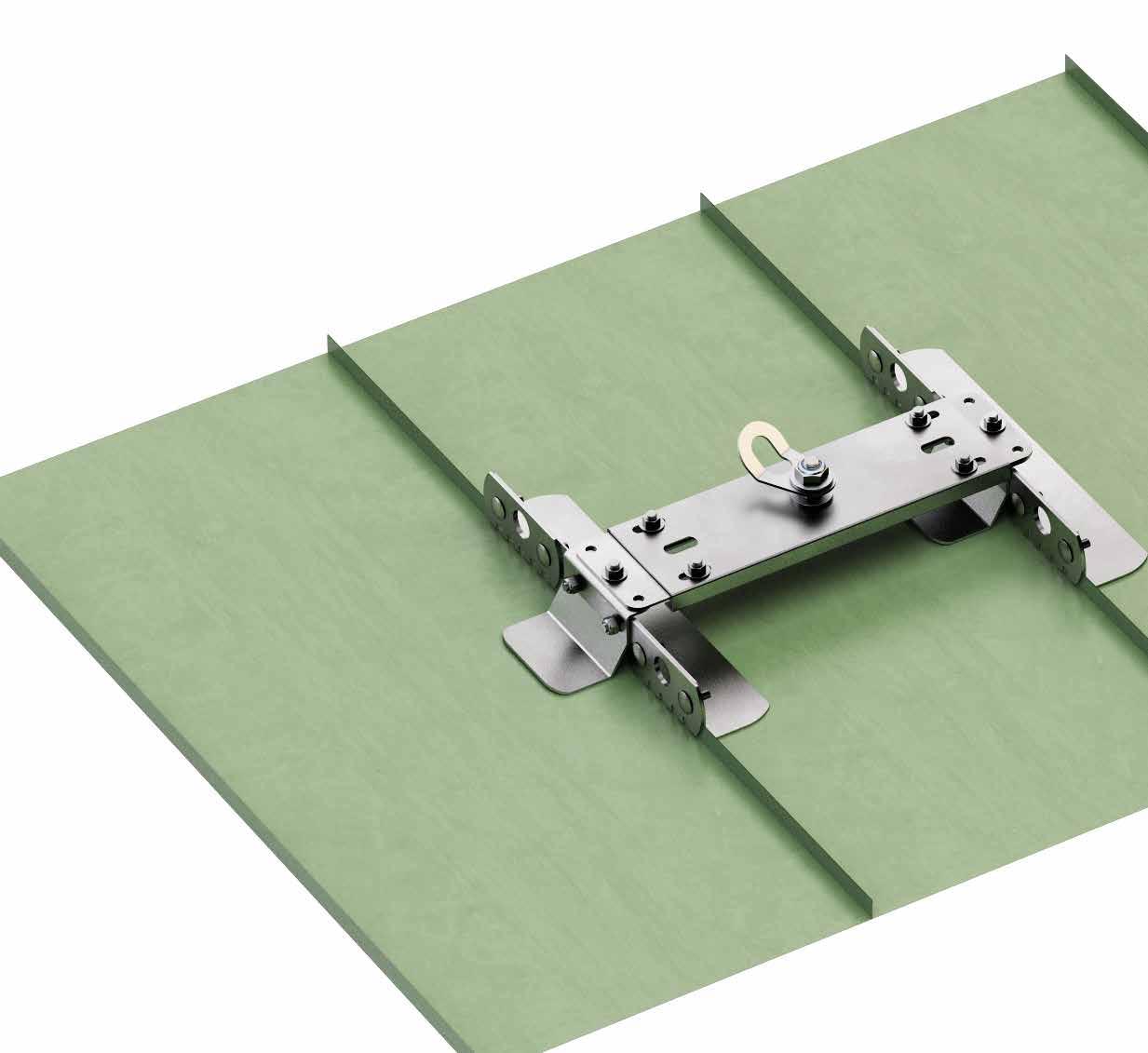
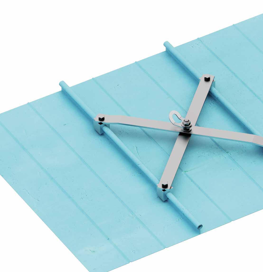
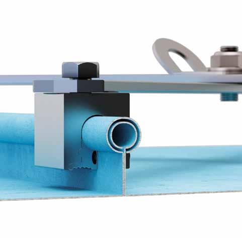
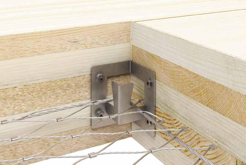
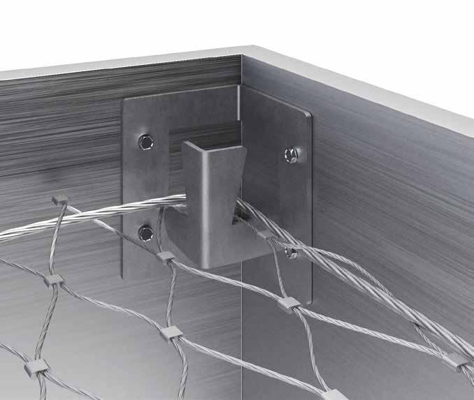
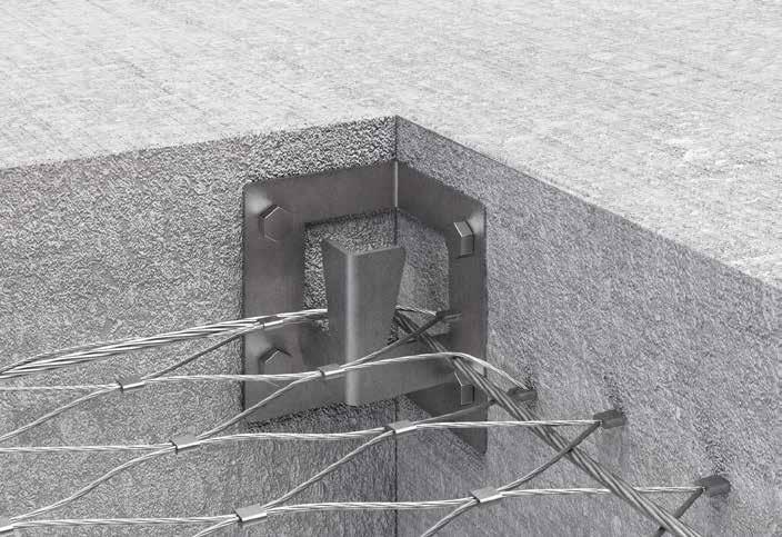
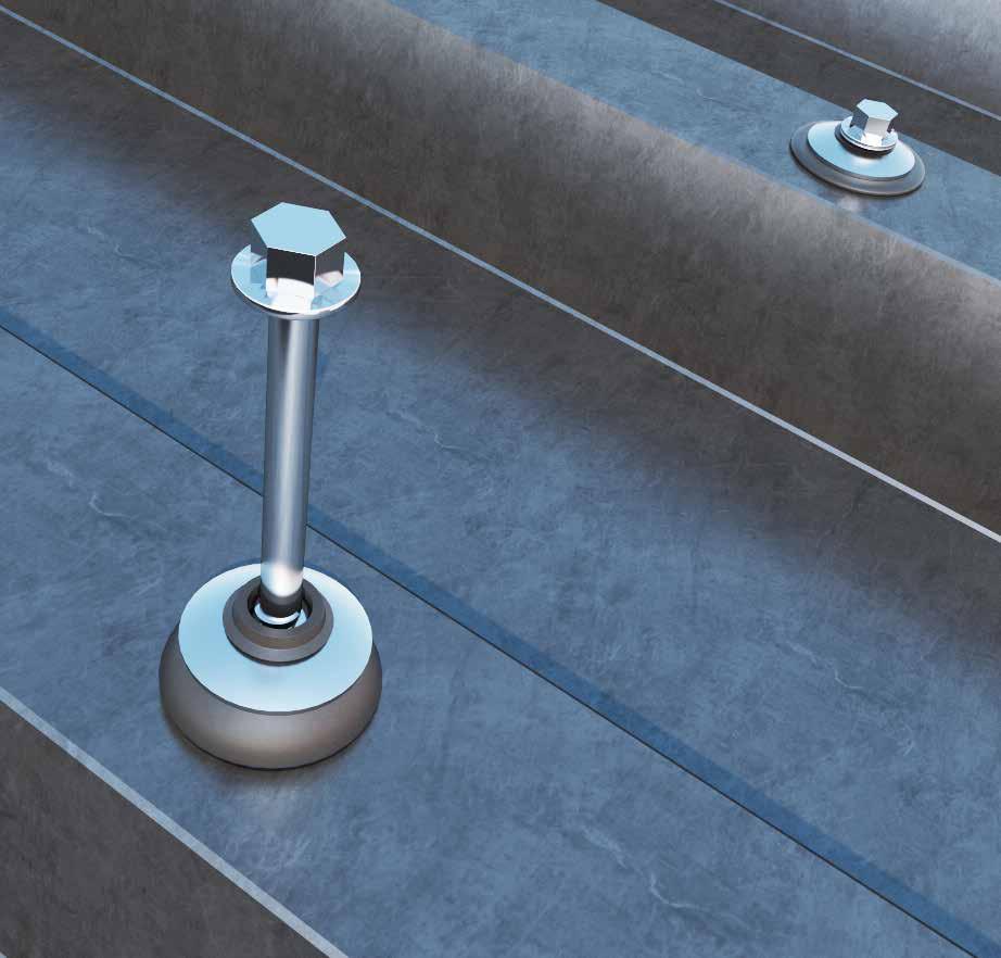
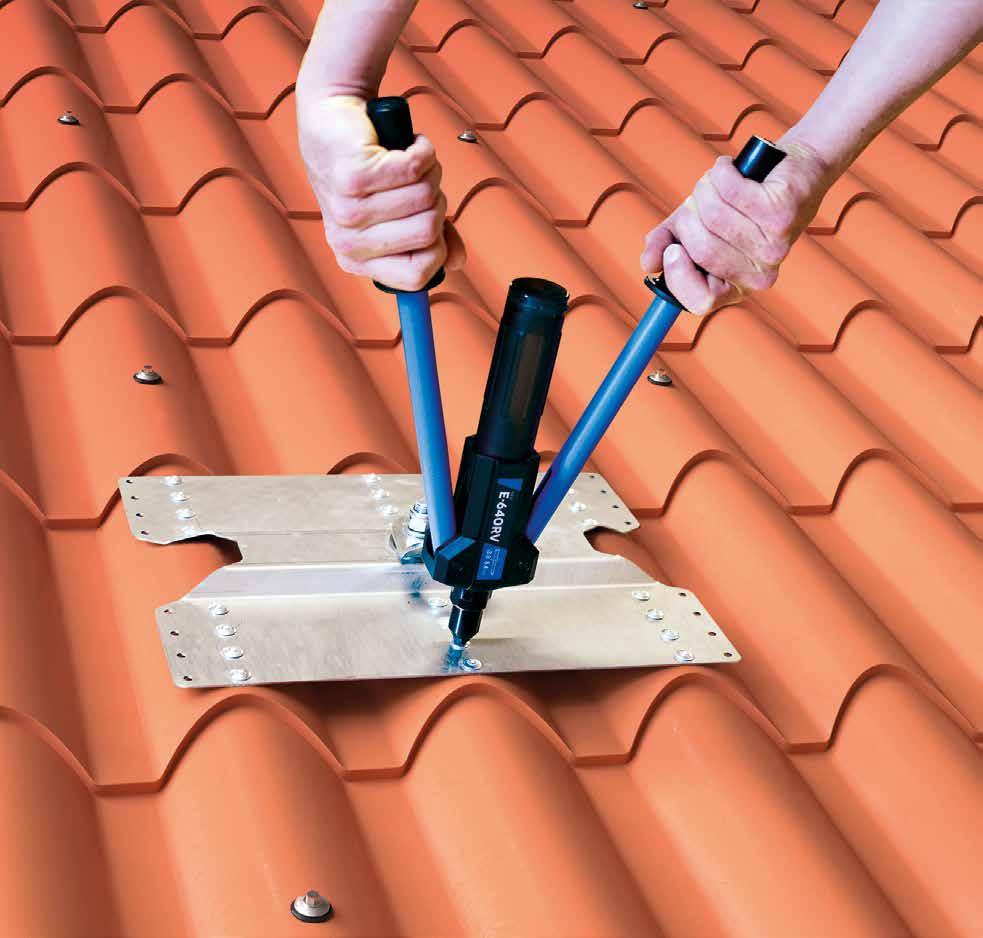
PATROL + SIANK 4 | SIANKINT
LIFELINE ON SUPPORT FOR STANDING SEAM METAL ROOFS
PRACTICAL
The system can be installed on existing roofs without having to remove the metal sheet.
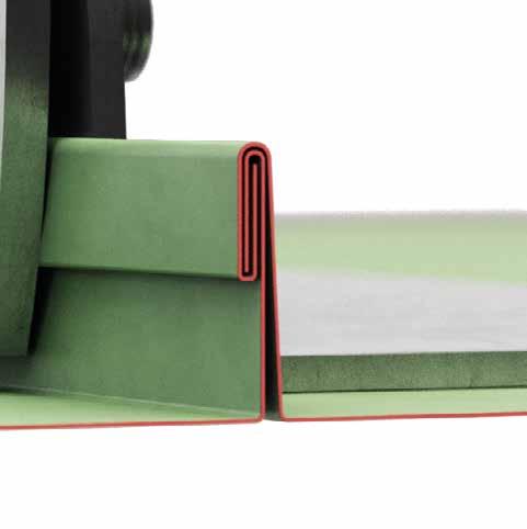
SAFE
Installation does not require the sheet metal to be drilled, thanks to the gripper which distributes the load over the double seam, thus ensuring the integrity of the building envelope.
SIMPLE
Designed to ensure quick and easy assembly with just a few tools.
Installation of a PATROL lifeline with SIANK 4 supports on standing seam sheet.
TECHNICAL DATA*
deflection
xmin siank
* The values indicated are the result of experimental tests carried out under the supervision of third parties in accordance with the standard referred to. For a calculation report with minimum distances according to the relevant standard requirements, the substructure must be checked by a qualified engineer before installation.
SIANK 4 | CODES AND DIMENSIONS
SIANKINT | CODES AND DIMENSIONS
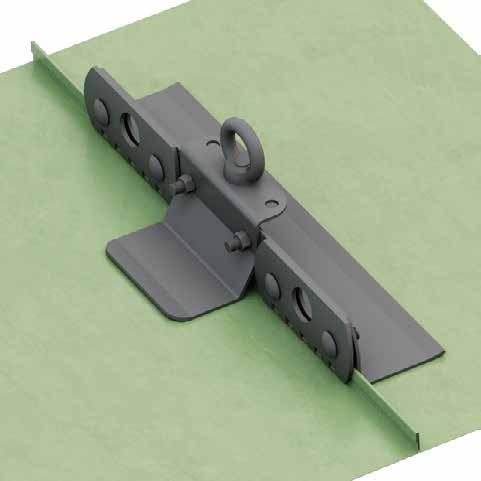
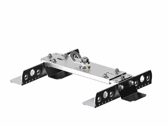
PATROL + SEAMO
LIFELINE ON SUPPORT FOR ROUND SEAM METAL ROOFS
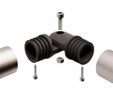
PRACTICAL
Device to be fastened to the seam with four clamps, without the need to make openings in the sheet metal.
SAFE
The fastening is done on two round seams of the sheet, to ensure greater strength.
SIMPLE
Fast and safe assembly on different spacing between seams.
Installation of a PATROL lifeline with SEAMO brackets on round seams
TECHNICAL DATA*
substructure minimum thickness
deflection
2 PATROLTERM / PATROLTERML
3 SPEAR2
4 PASINT / PATROLMED / PATROLINT
5 SLIDE1 / SLIDE2
6 CABLE
ALUFALZ, INTERFALZ, BEMO ROOF, KALZIP
* The values indicated are the result of experimental tests carried out under the supervision of third parties in accordance with the standard referred to. For a calculation report with minimum distances according to the relevant standard requirements, the substructure must be checked by a qualified engineer before installation.
SEAMO | CODES AND DIMENSIONS
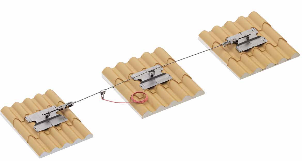
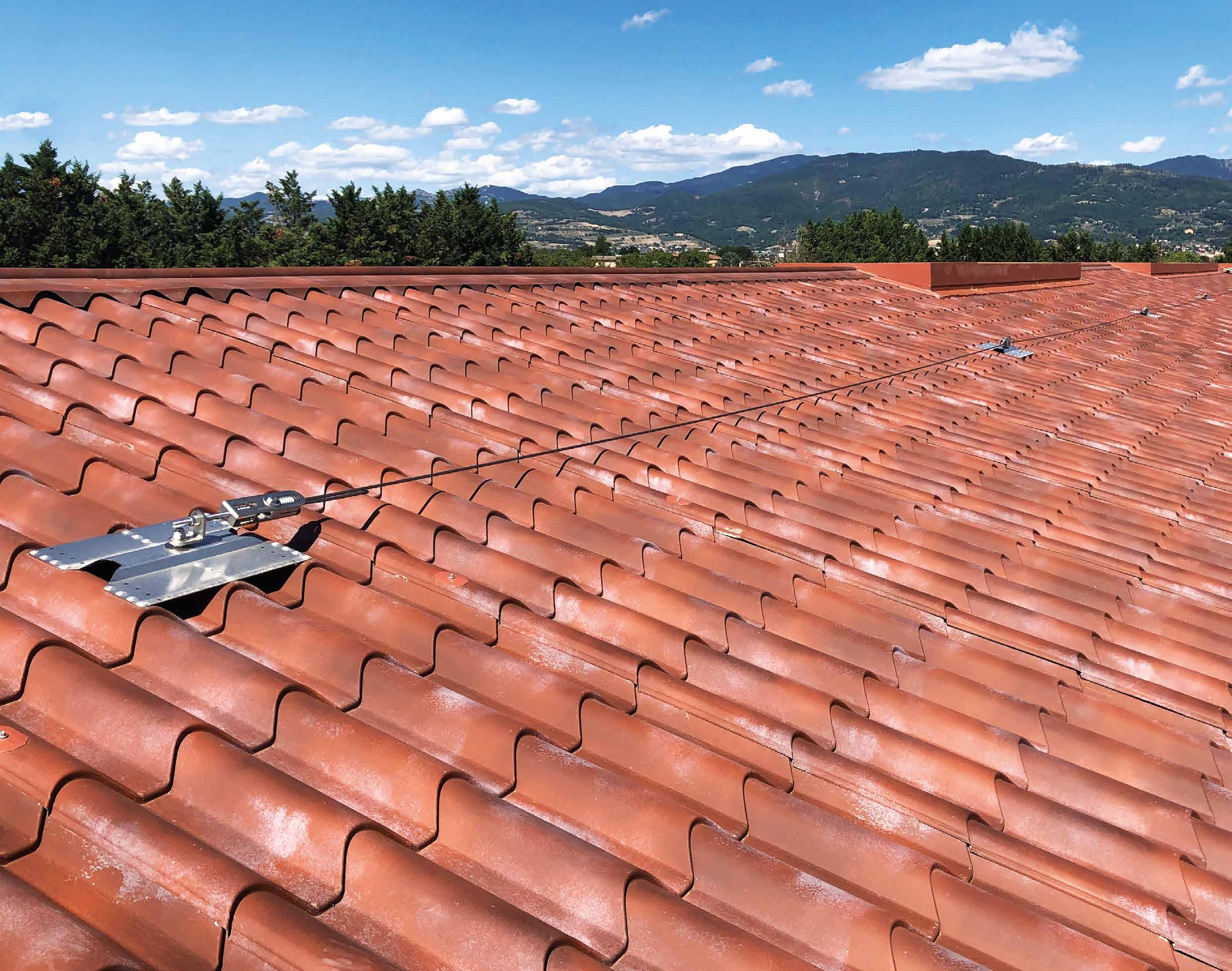
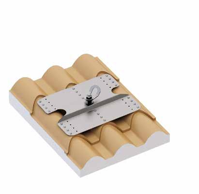
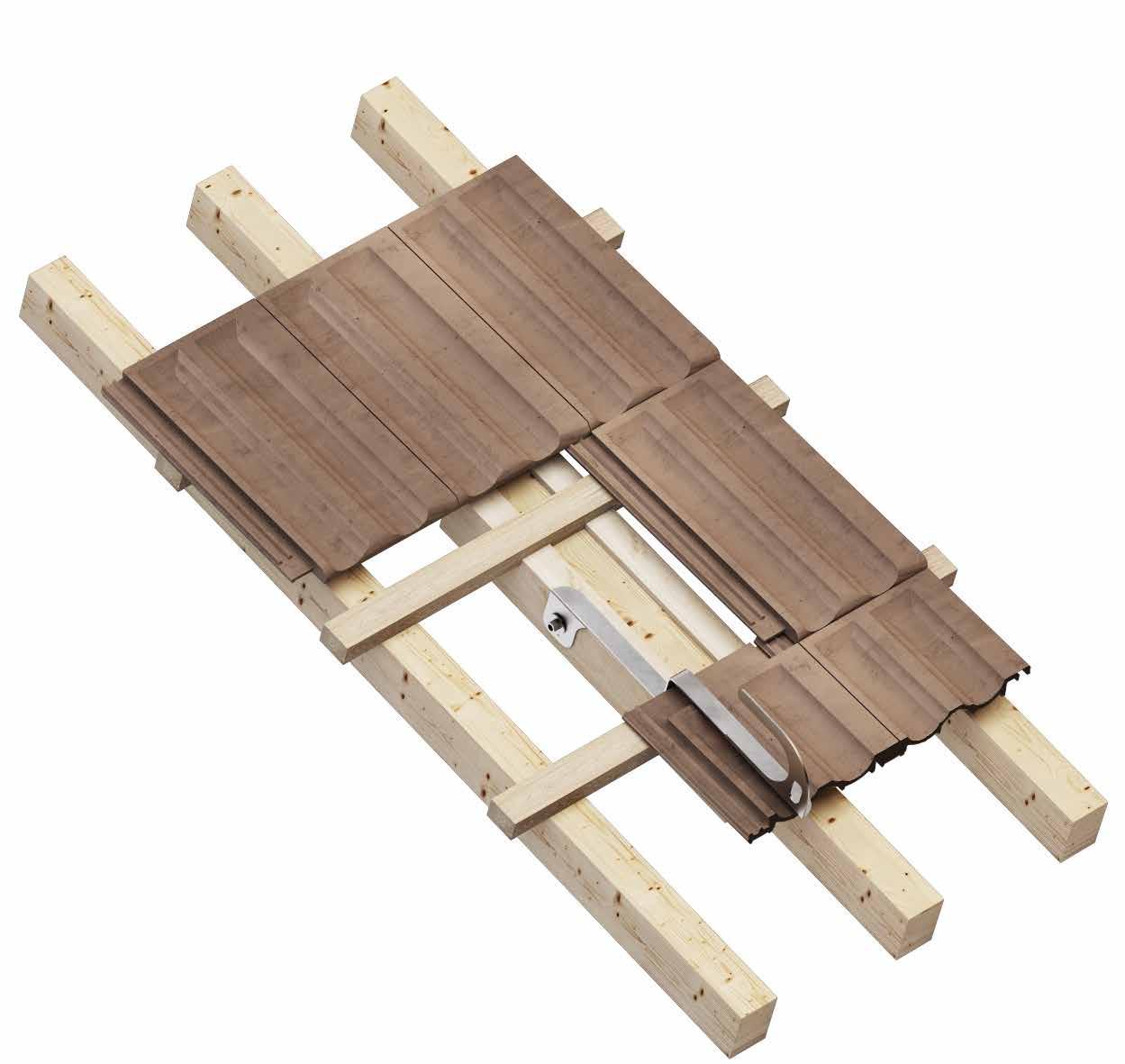
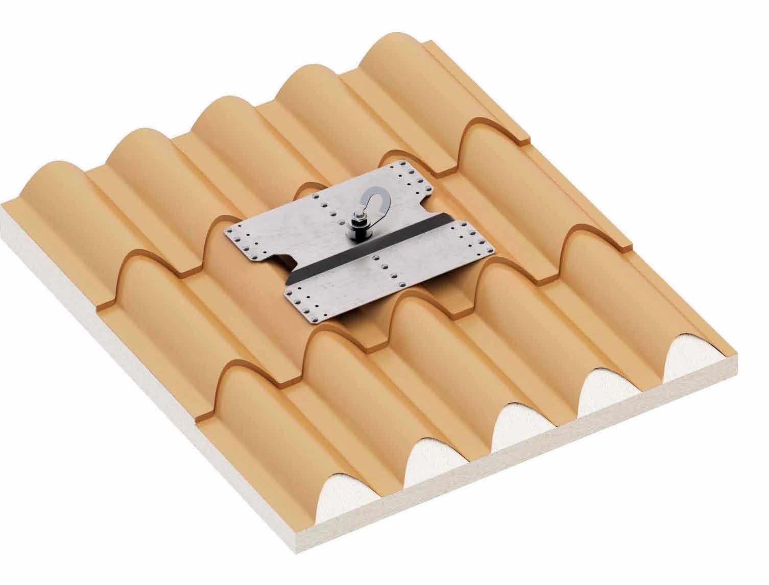
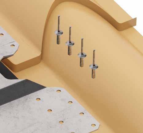
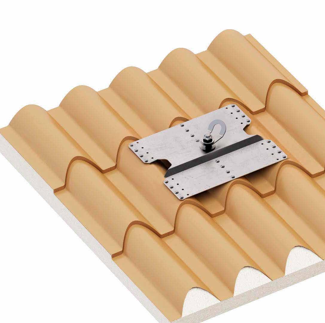
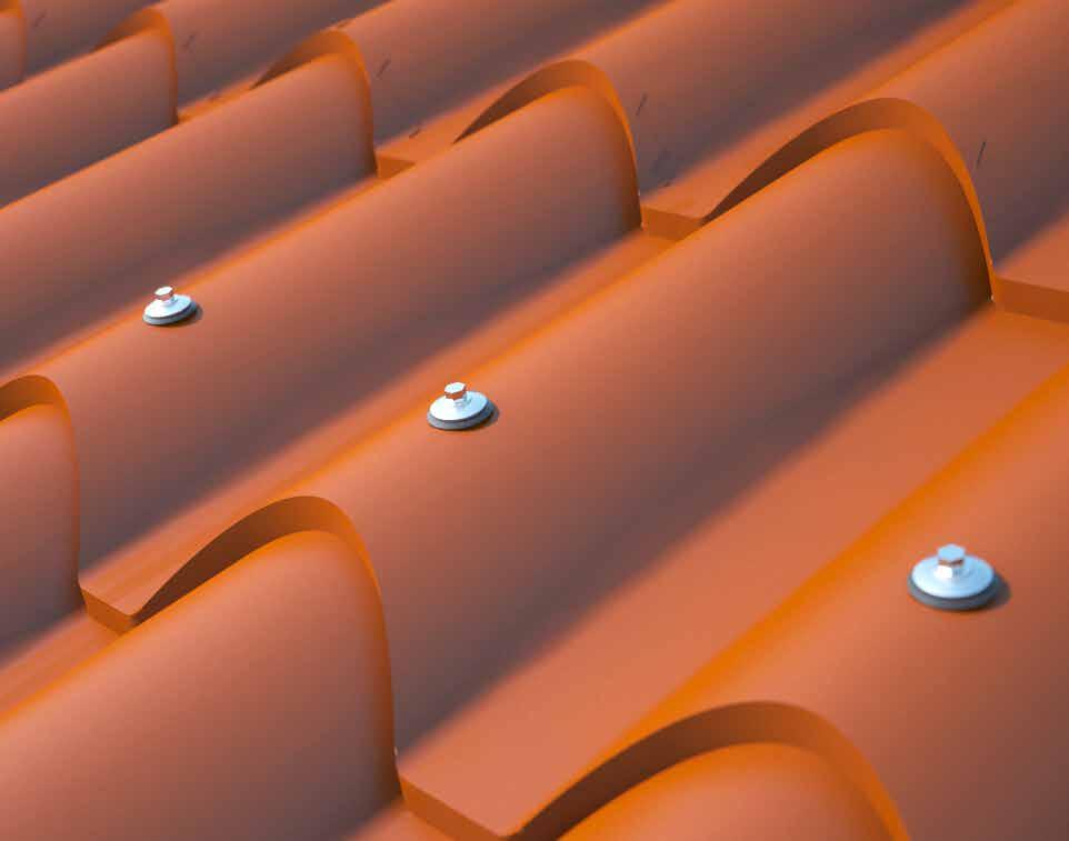
PATROL + COPPO
LIFELINE ON SUPPORT FOR ROOFS WITH FAUX TILES
COMPLETE
The package includes fasteners and cellular rubber seals, to ensure roof waterproofing.
ADJUSTABLE
Pre-drilled plate with holes at different distances to suit various types of sheet metal.
FAST
Very quick assembly after covering with just a few tools.
Installation of a PATROL lifeline with COPPO supports on a sandwich panel of the "faux tiles" type
2 PATROLTERM / PATROLTERML
3 SPEAR
4 PASINT / PATROLMED / PATROLINT
5 SLIDE 1 / SLIDE 2
6 CABLE
TECHNICAL DATA*
substructure minimum thickness fastening systems included
mm rivet 6,3 x 20,2 mm with EPDM washer (x 24)
* The values indicated are the result of experimental tests carried out under the supervision of third parties in accordance with the standard referred to. For a calculation report with minimum distances according to the relevant standard requirements, the substructure must be checked by a qualified engineer before installation.
COPPO | CODES AND DIMENSIONS
COPPO
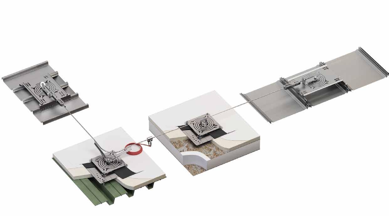
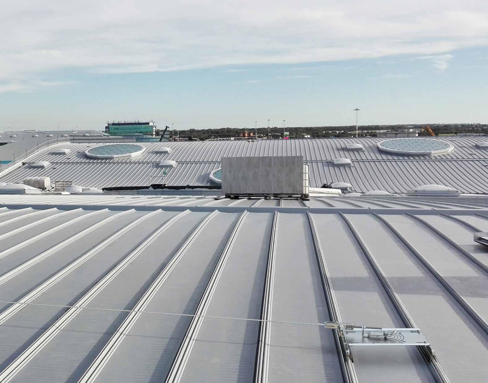
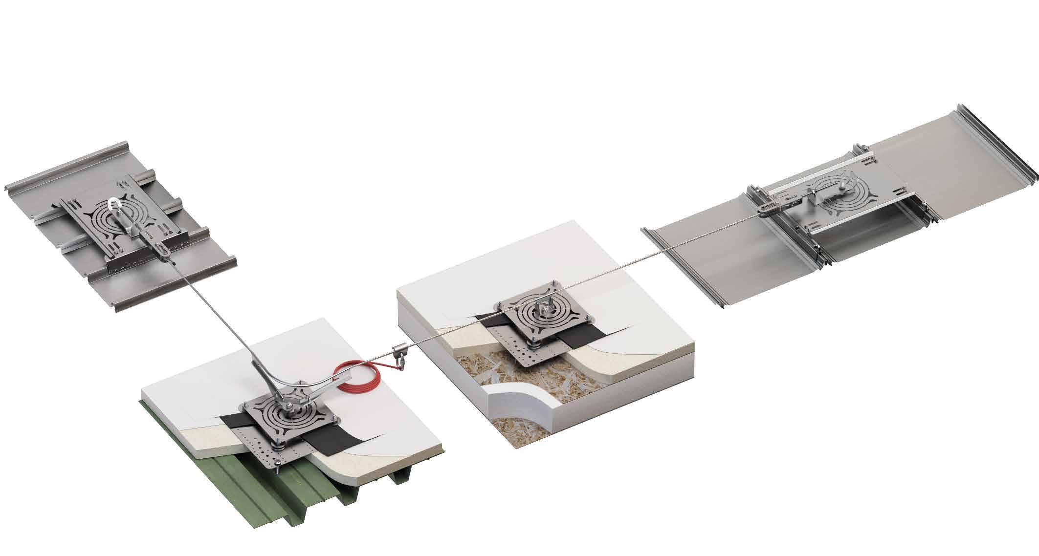
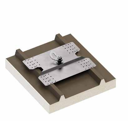
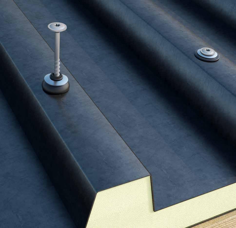
PATROL + TWIST
LIFELINE ON SUPPORT FOR CONTINUOUS ROOFS AND PVC/TPO AND OSB ROOFS
UNIVERSAL
Unique fall absorption system offering solutions on several types of structure.
ADJUSTABLE
The various sizes of the bottom plates guarantee a solution for every substructure and sheet metal option.
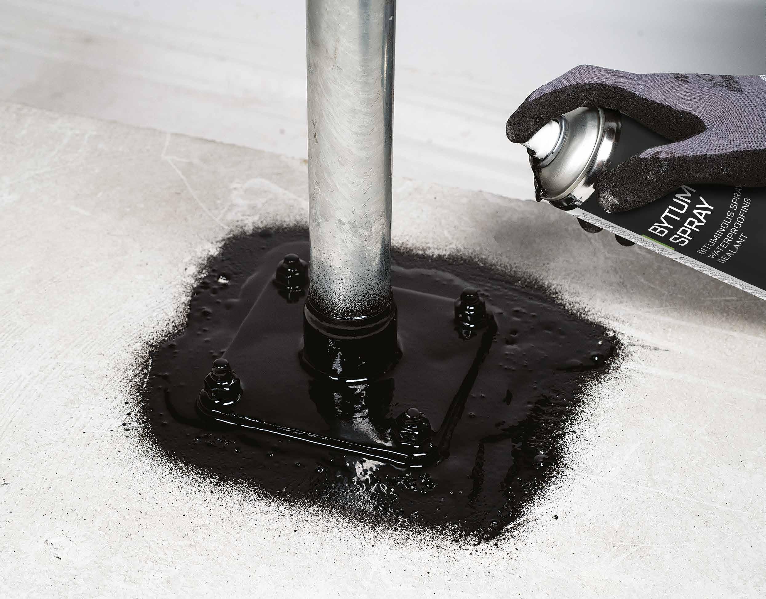
SAFE
Certified fastening kits and installation accessories ensure that the structure is waterproofed to the highest standard.
Installation of a PATROL lifeline with TWIST supports for continuous roofing.
TWIST | CODES AND DIMENSIONS
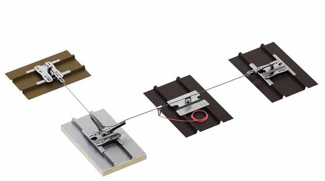
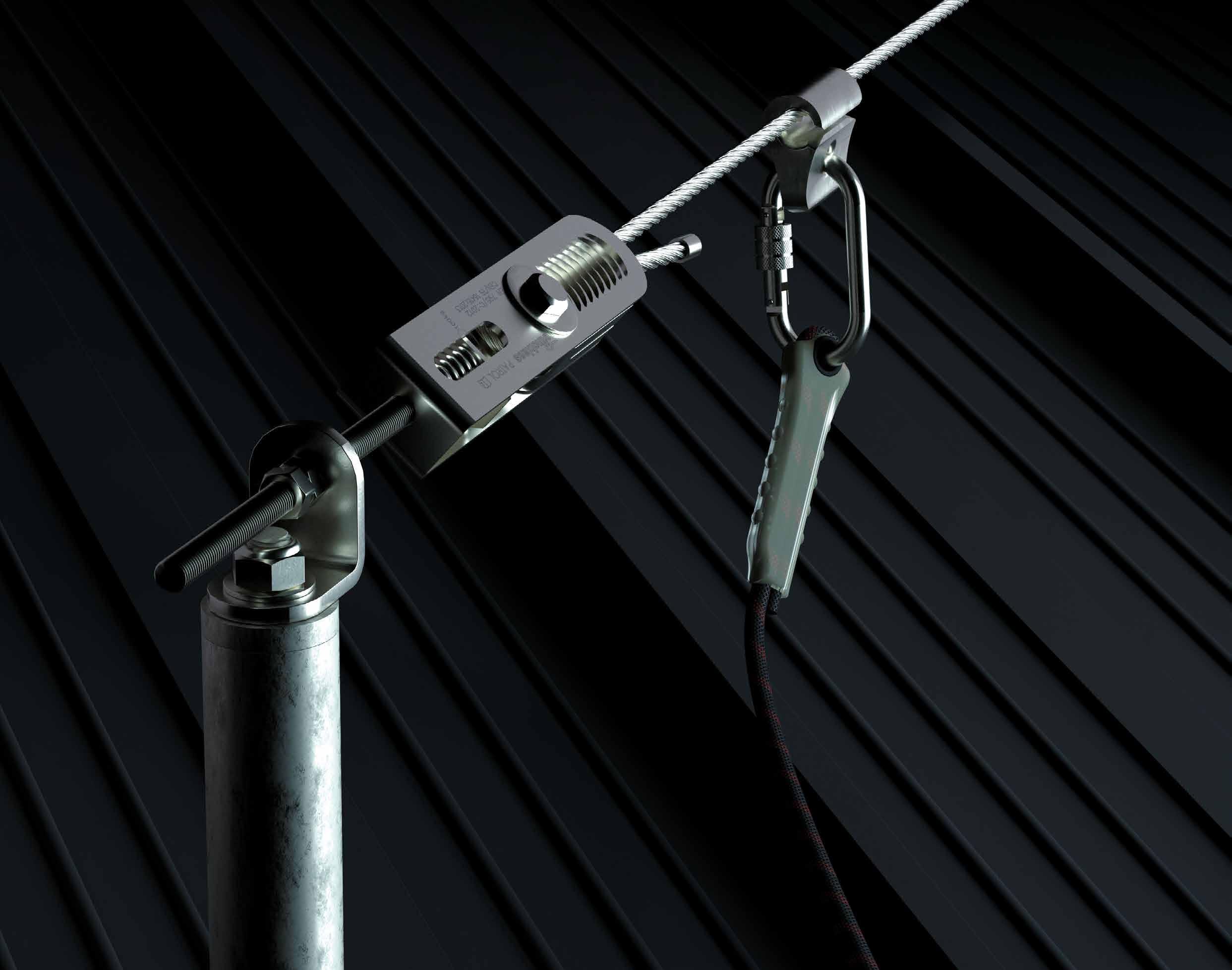
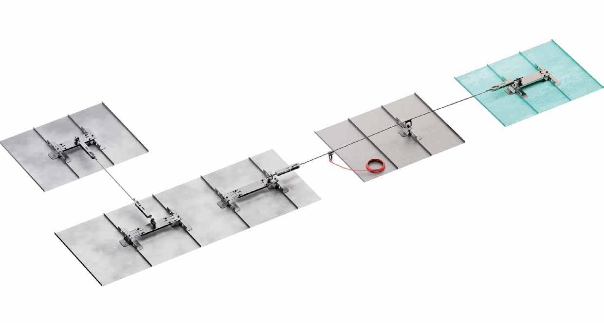
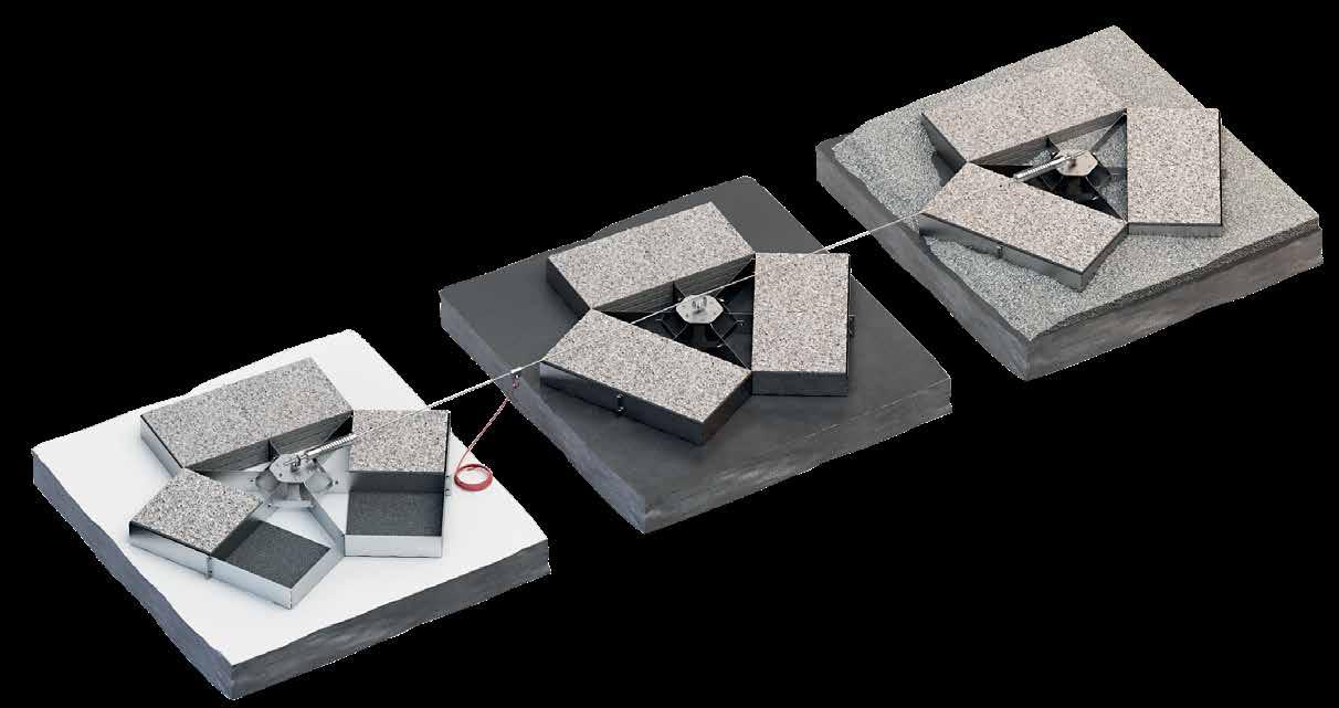
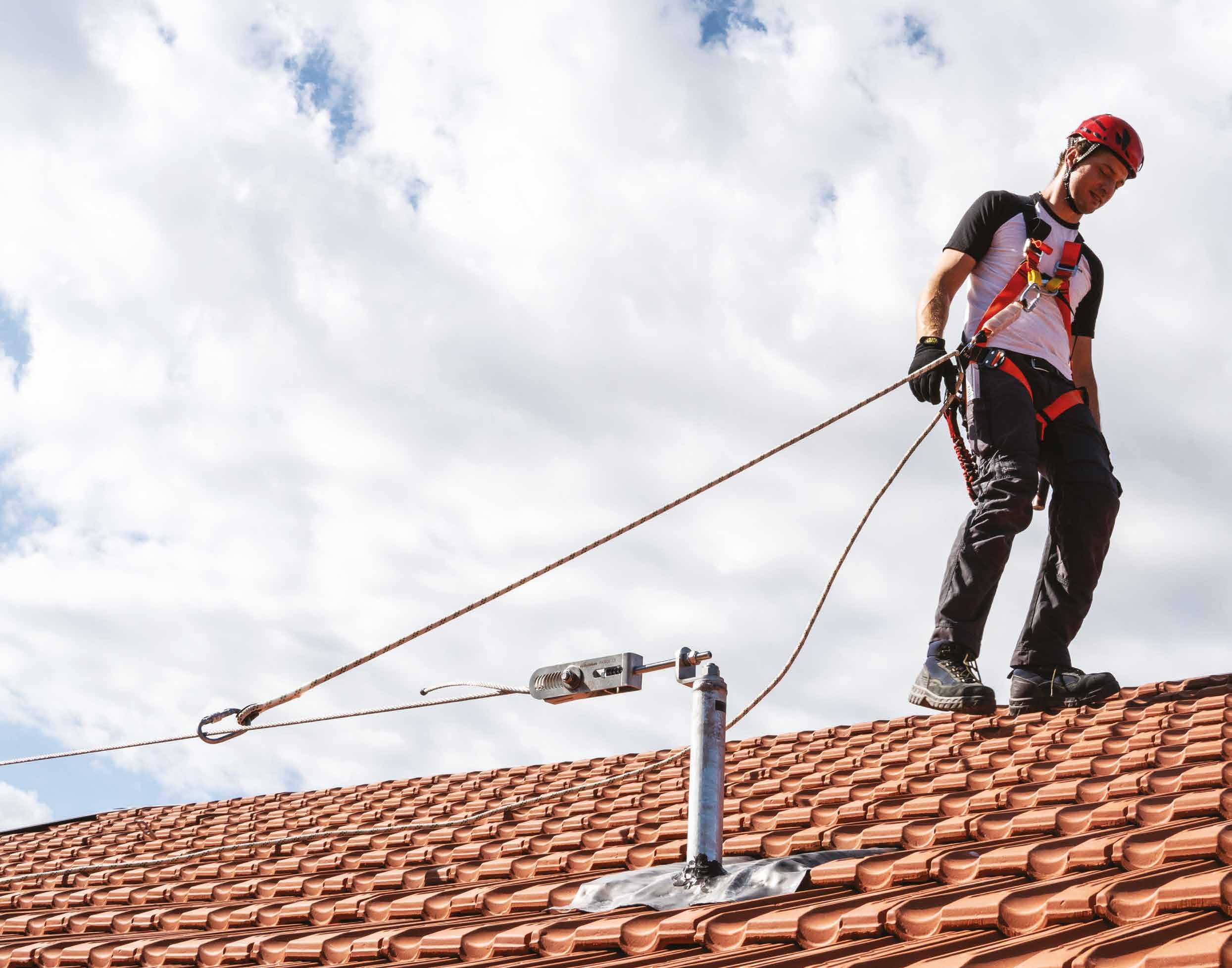
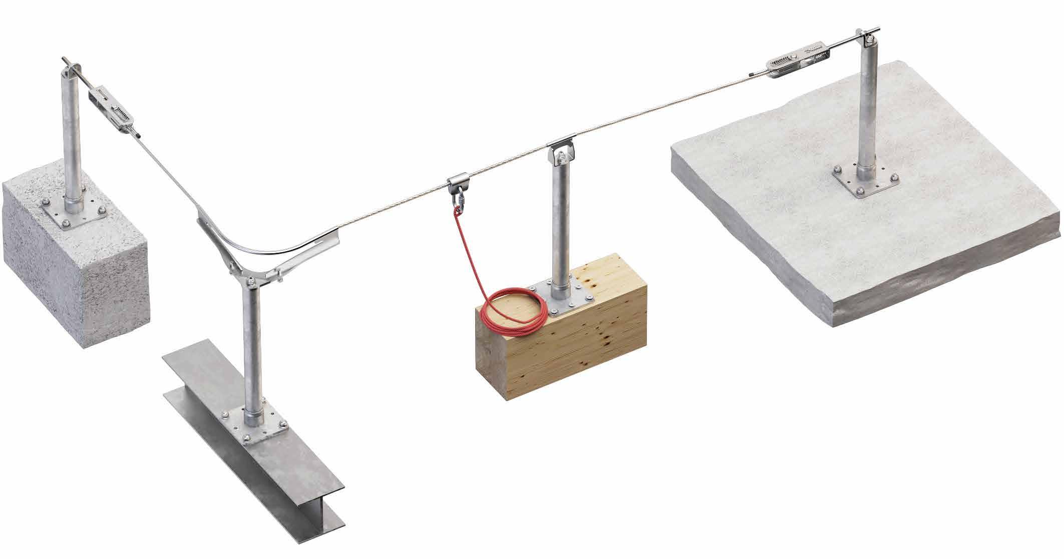
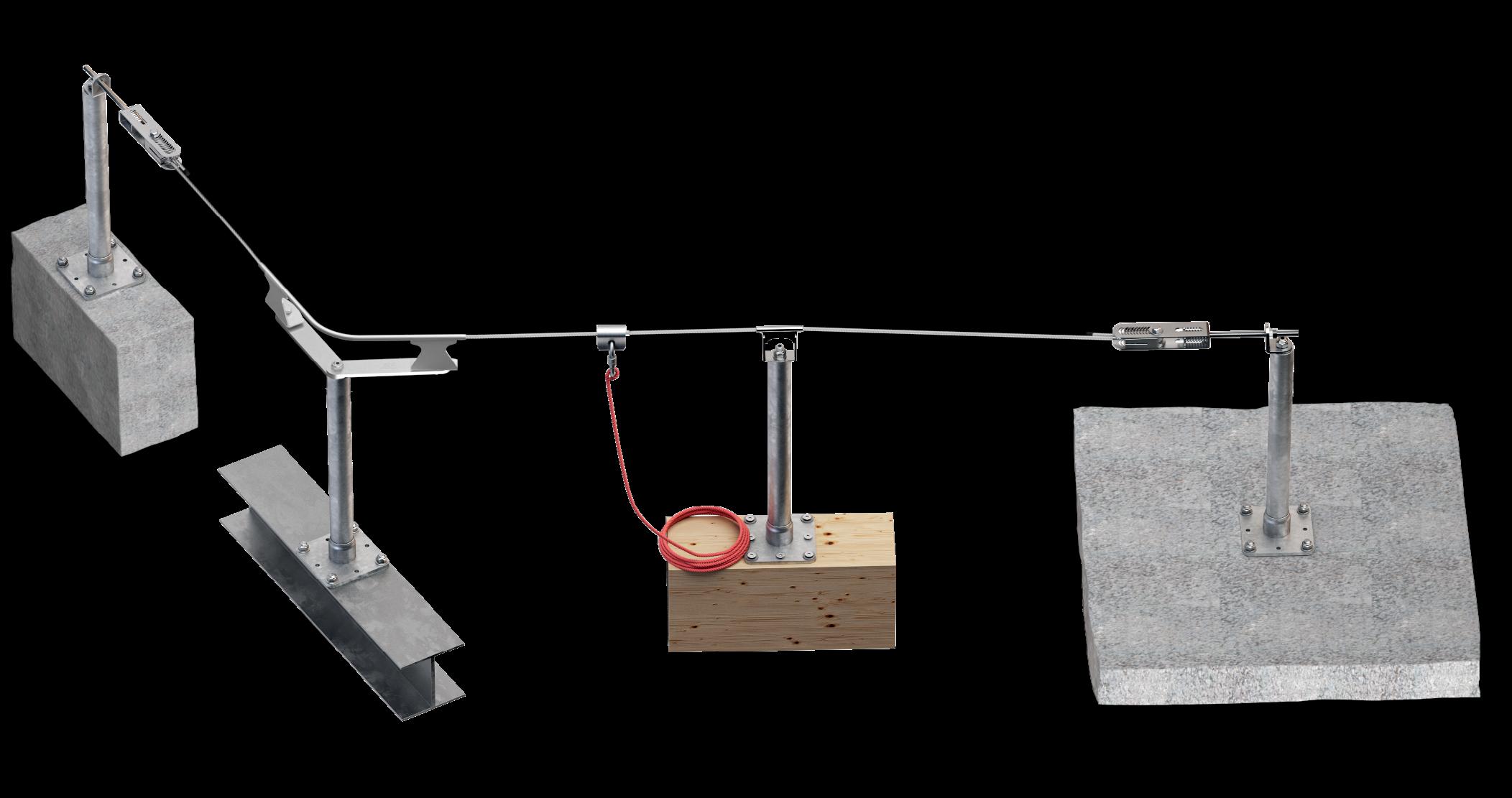
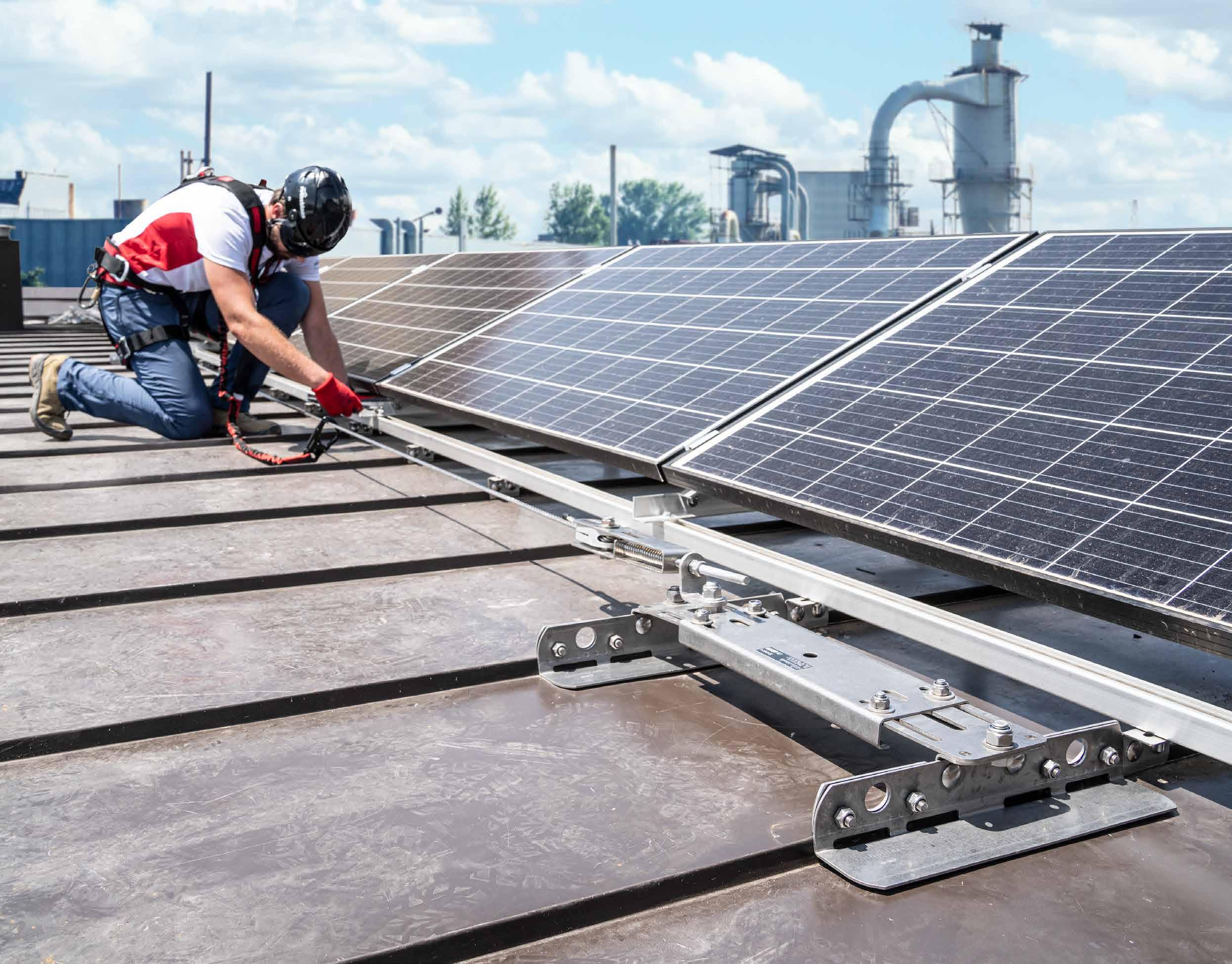
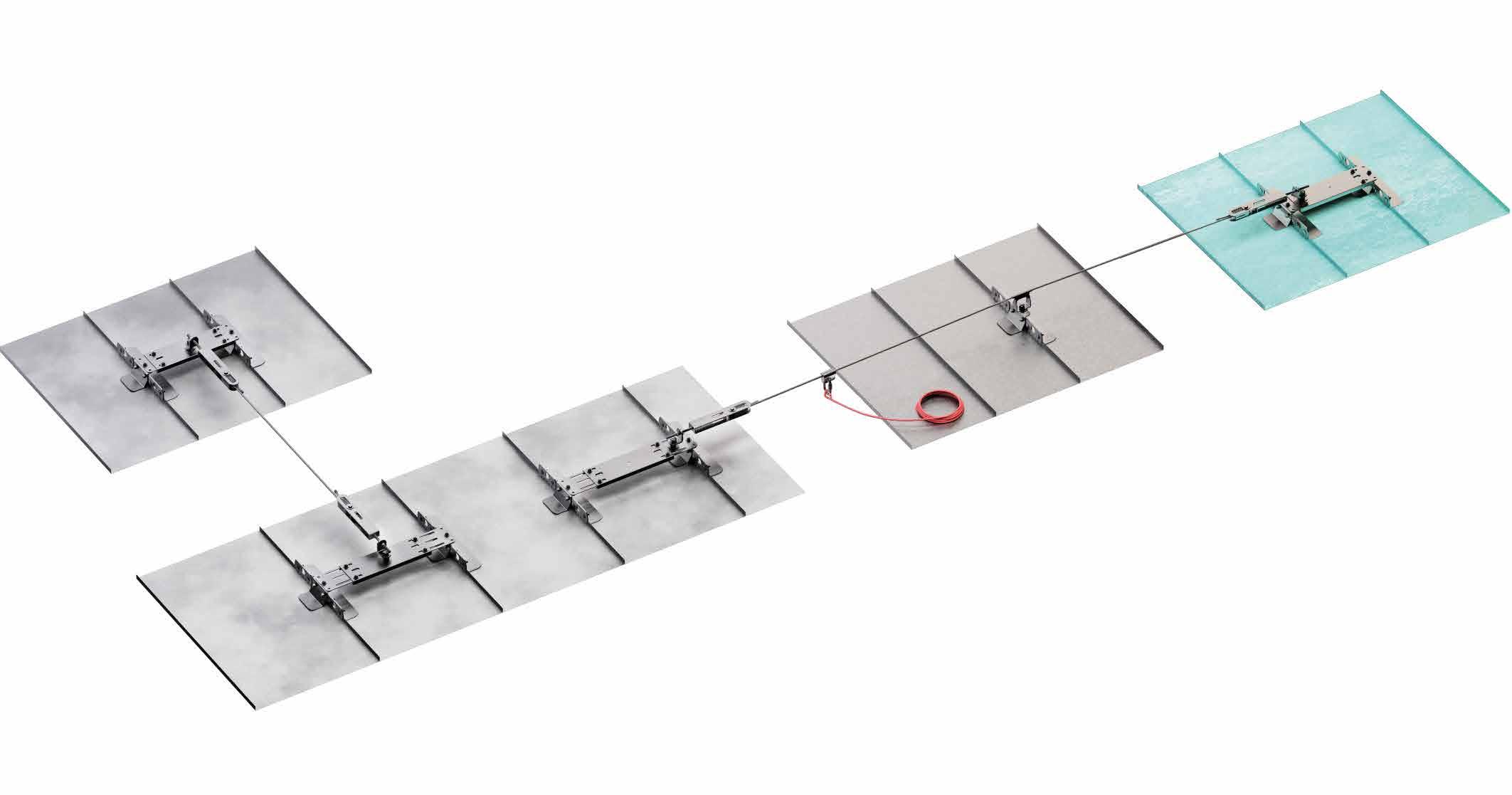
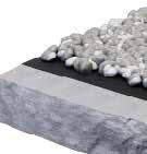
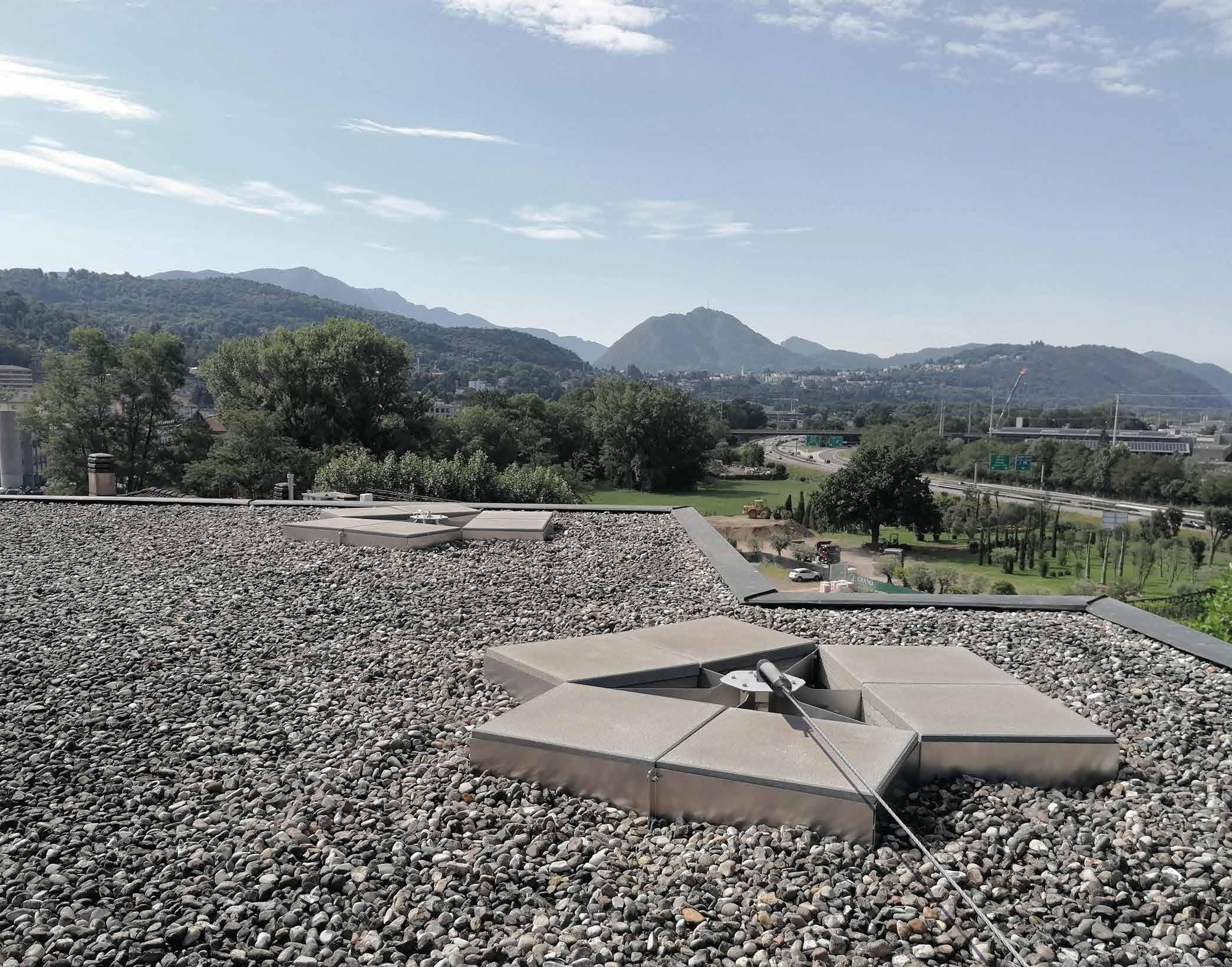
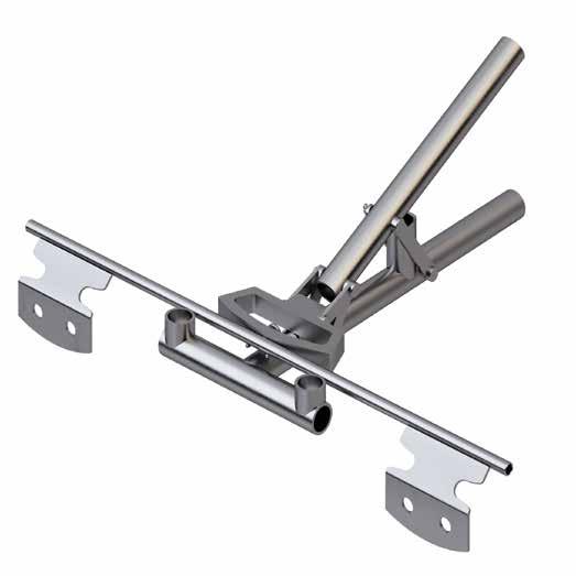
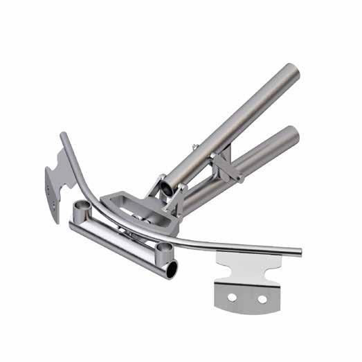
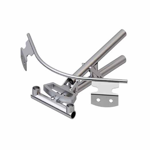
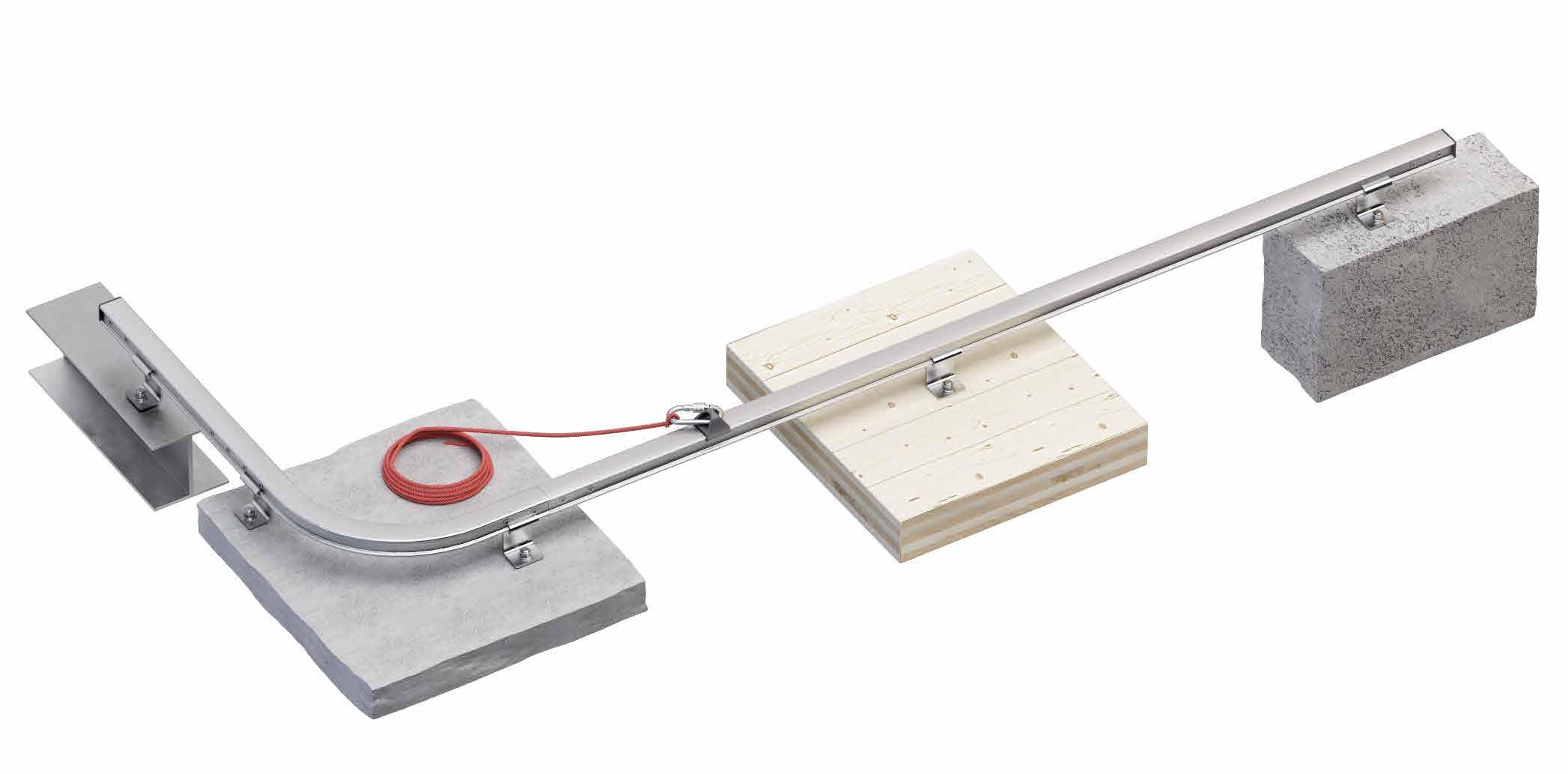
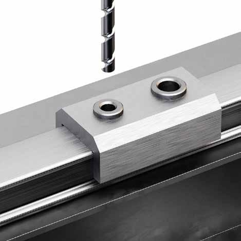
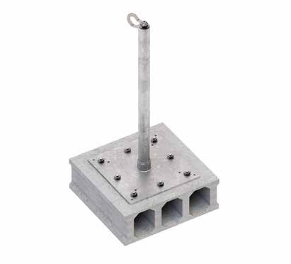
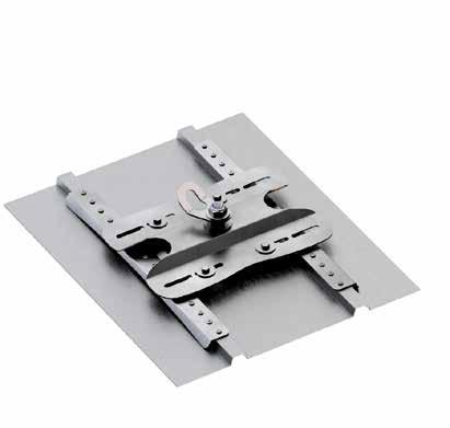
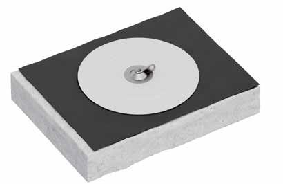
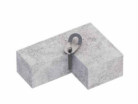
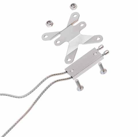
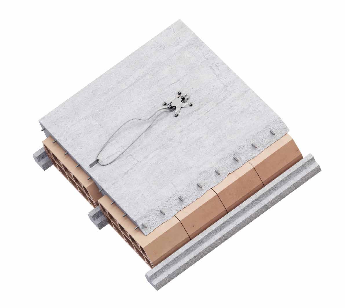
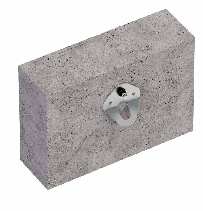
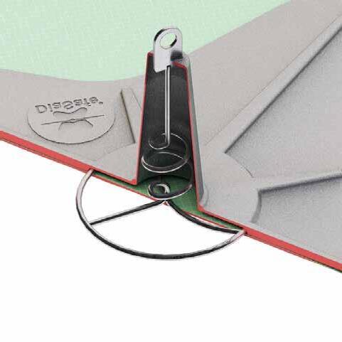
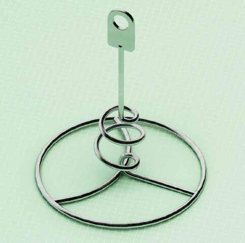
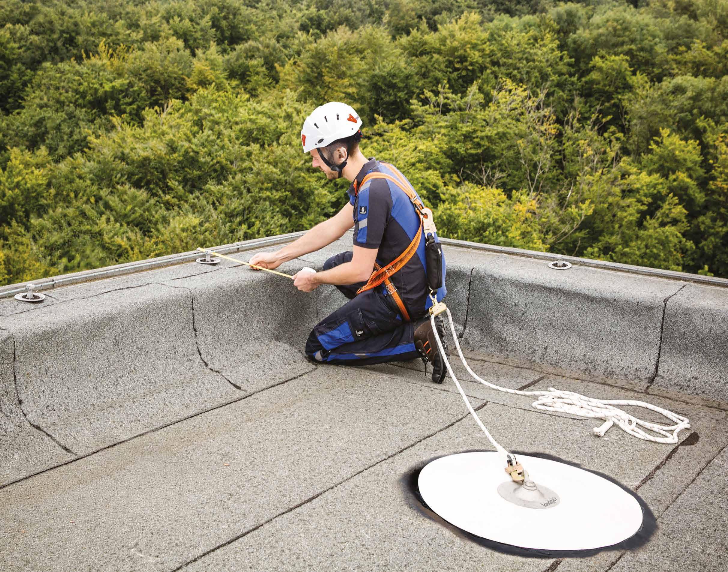
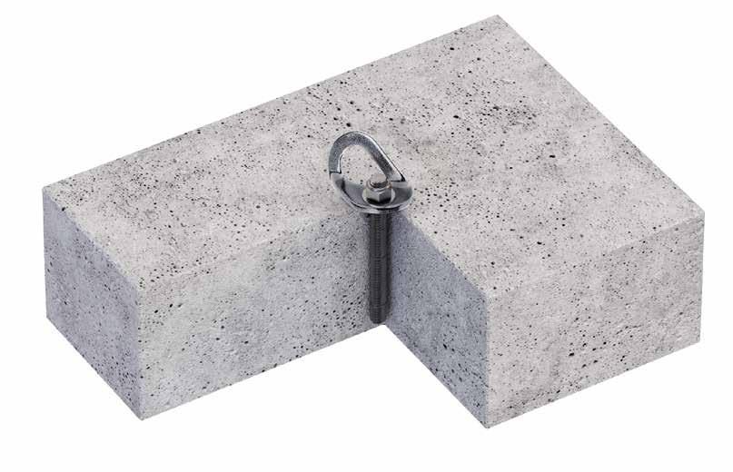
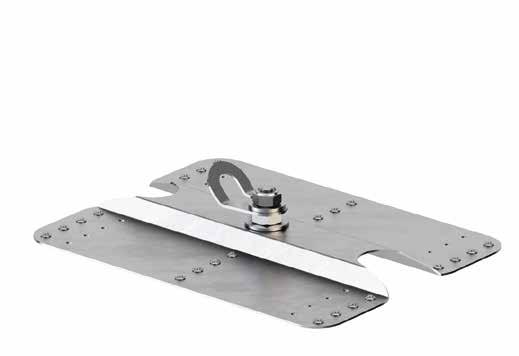
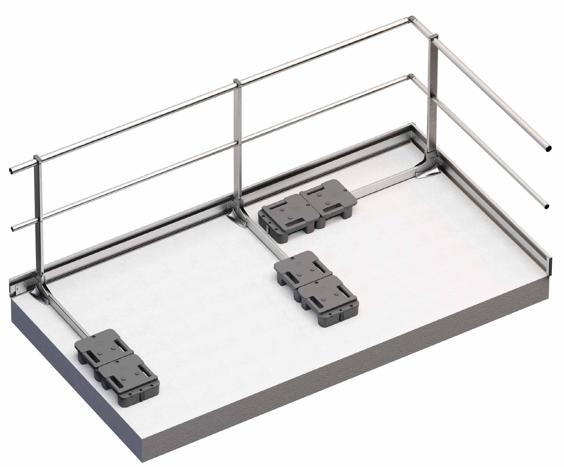
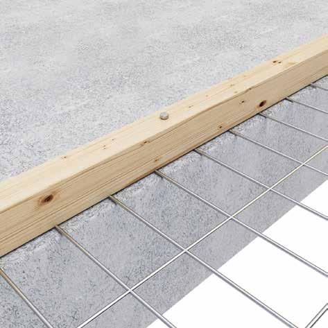
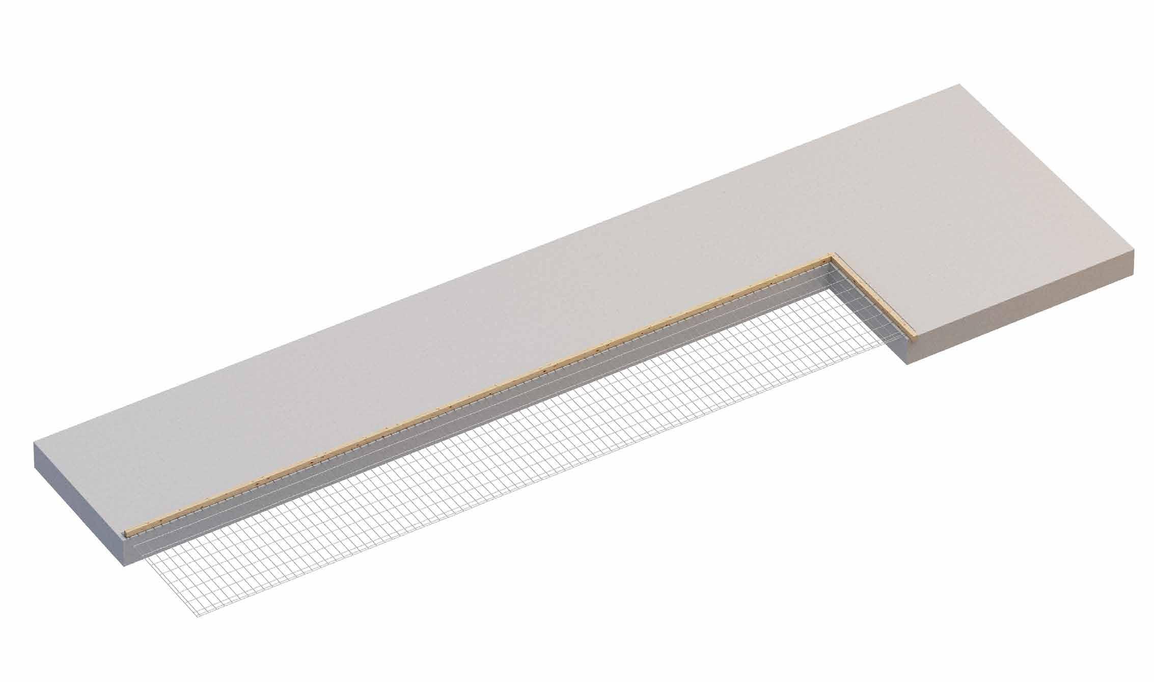
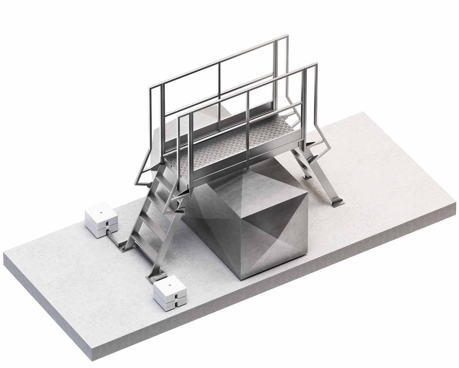
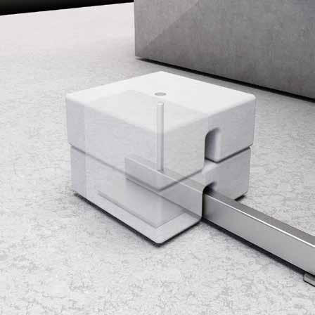
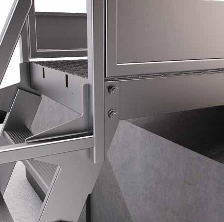
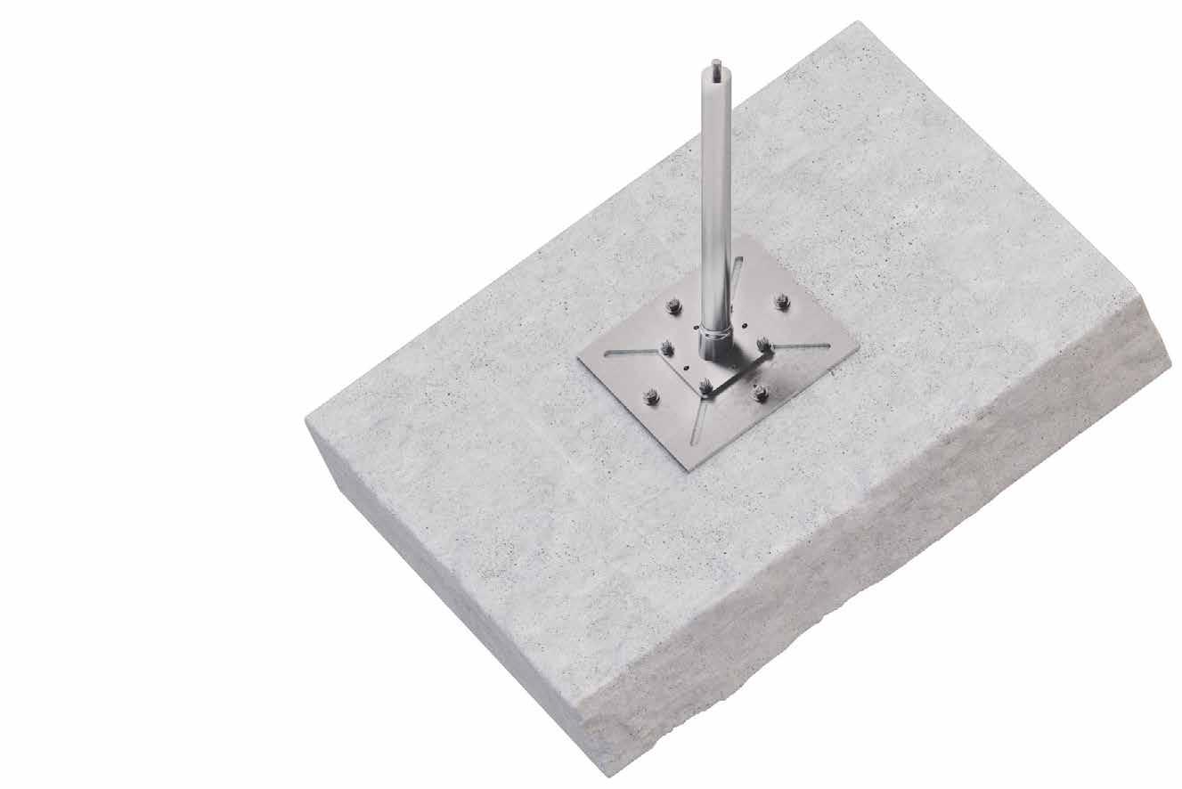
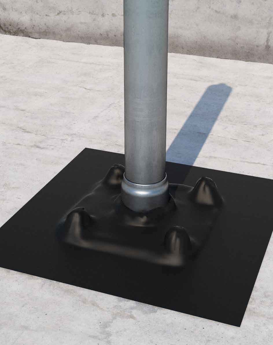
PATROL + BLOCK
LIFELINE ON SUPPORT WITH BALLAST FOR FLAT ROOFS
WITHOUT DRILLING
It is designed for installation on flat roofs, and does not require to drill the roof covering, avoiding thermal bridges and preserving the waterproofing layer of the structure.
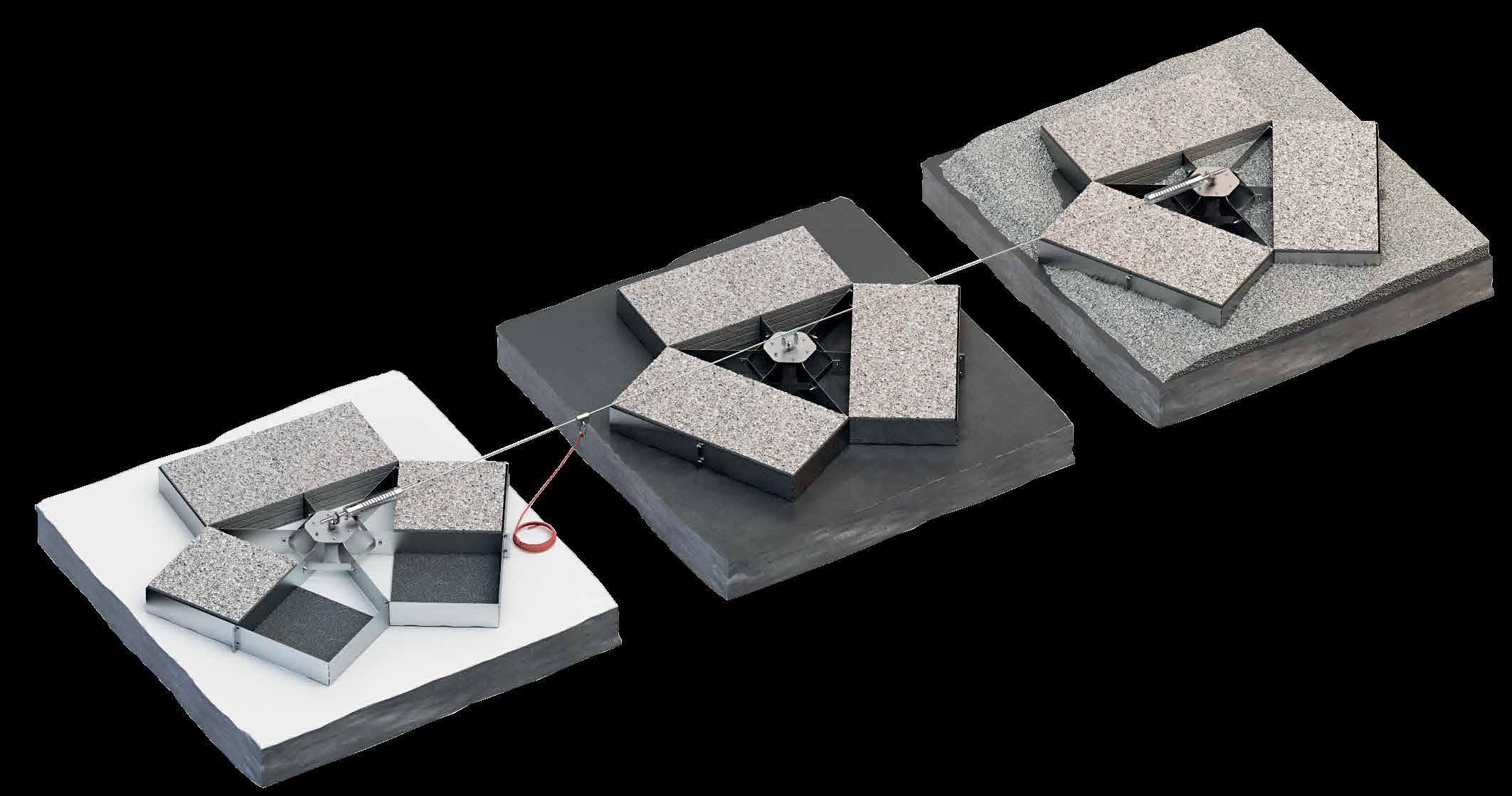
FLAT ROOFS
Designed for flat roofs with inclines up to 5° with PVC or bituminous final covering, with or without gravel.
SIMPLE
Concrete ballast slabs in standard sizes.
Installation of a PATROL lifeline on a flat roof using BLOCK ballast supports.
* The values indicated are the result of experimental tests carried out under the supervision of third parties in accordance with the standard referred to. For a calculation report with minimum distances according to the relevant standard requirements, the substructure must be checked by a qualified engineer before installation. with SPEAREVO xmax
BLOCK | CODES AND DIMENSIONS
COMPLEMENTARY PRODUCTS
BLOCKMAT (1) BLOCKMAT mats not included in the supply of the BLOCK item (3 pieces per BLOCK are required) it can be ordered separately.
(1) Concrete slabs (500 x 500 x 40 mm) for ballasting not included (24
Example of single system composition EN 795:2012 C+E:
• BLOCK 1 pc
• BLOCKMAT 3 pcs
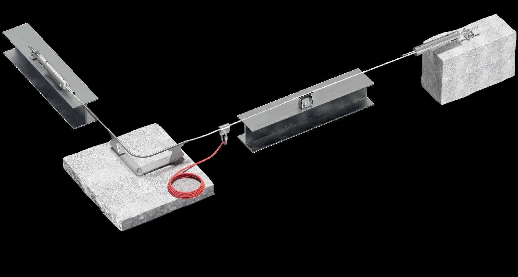
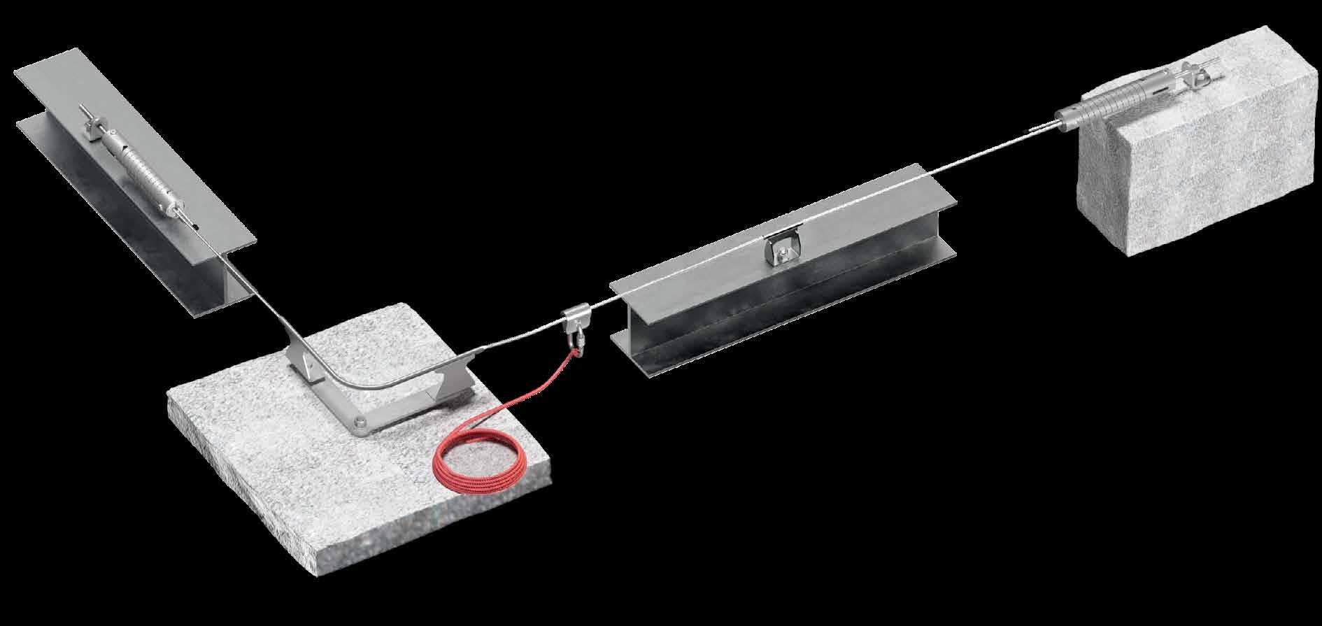
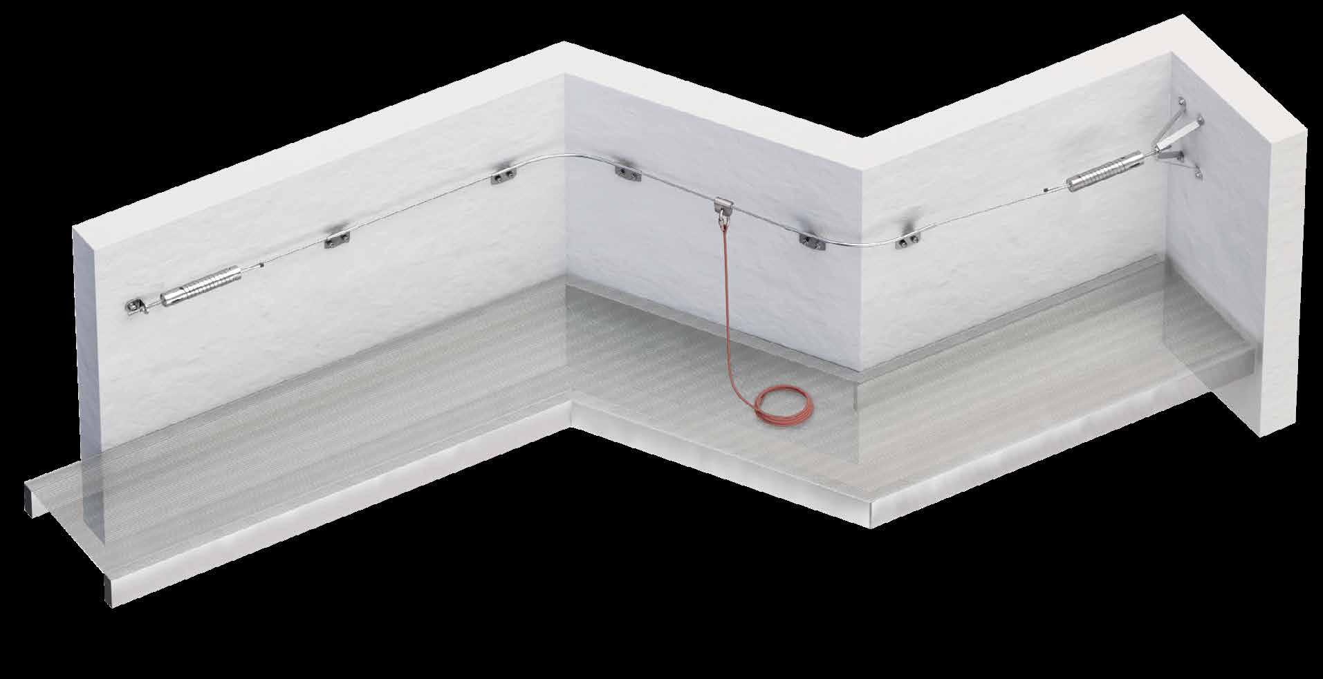
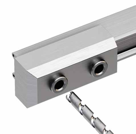
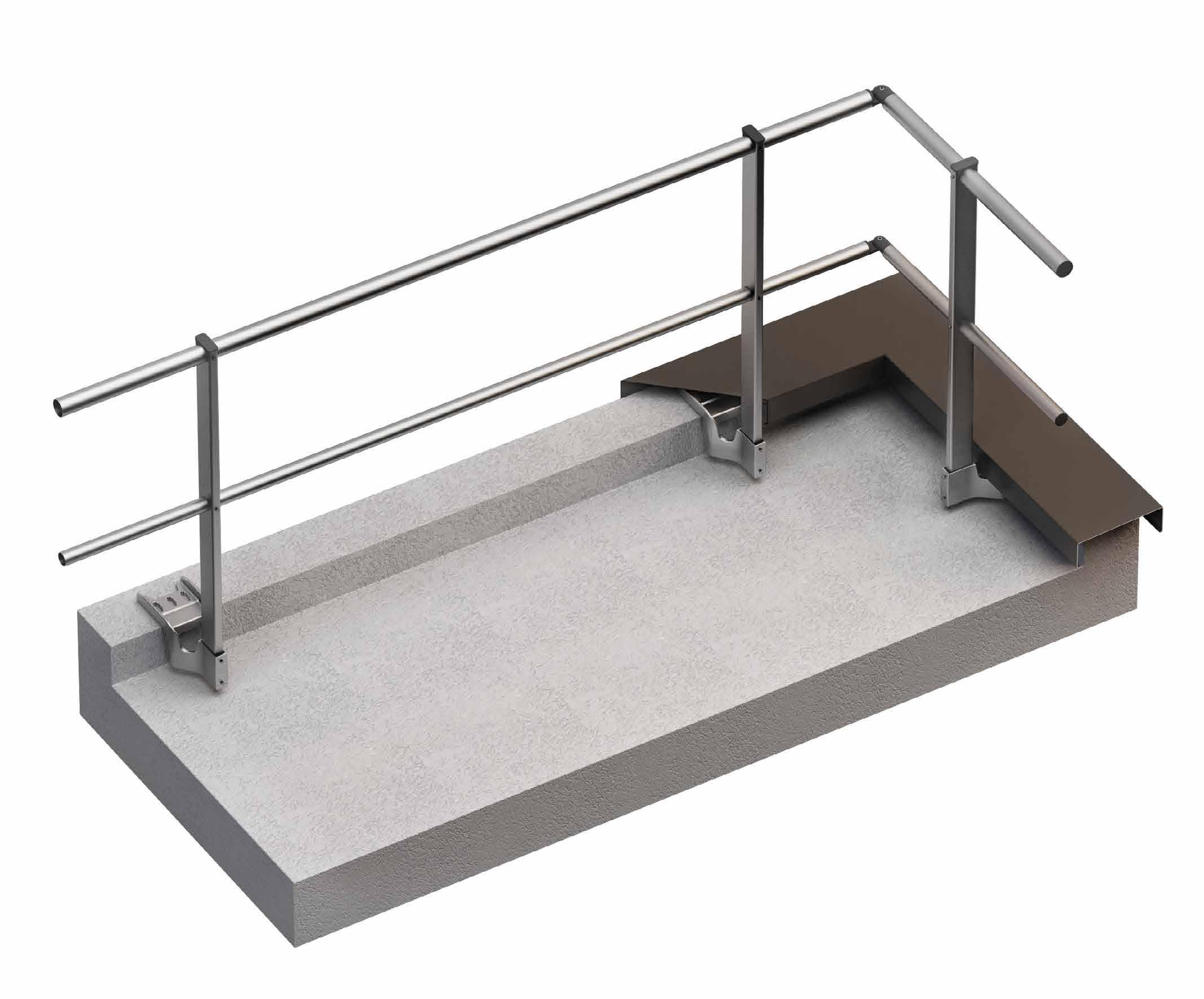
PATROL + PATROLEND
LIFELINE WITH DIRECT FASTENING ON STEEL AND CONCRETE SUBSTRUCTURES
EASY
Quick and easy assembly directly onto concrete or steel structure.
UNIVERSAL
System designed for different applications: flat, façade, overhead.
USE
Specially designed shuttles can be used to enable the operator to overcome bends and intermediate points without ever becoming disconnected from the system.
Installation
TECHNICAL DATA*
substructure minimum thickness fasteners
rod Ø16 AB7 M10 VIN
C20/25 140 mm
n. CODE 1 PATROLEND
2 SPEAREVO / SPEAR
3 PASANGBEND + ANGSUP / PASANG / PATROLANG
4 PASINT / PATROLMED / PATROLINT
5 SLIDE 1 / SLIDE 2
6 CABLE
S235JR 5 mm EKS + ULS + MUT EKS M10 +ULS+MUT with SPEAR with SPEAREVO NEW
VIN-FIX
HYB-FIX M10 VIN SKR CE
* The values indicated are the result of experimental tests carried out under the supervision of third parties in accordance with the standard referred to. For a calculation report with minimum distances according to the relevant standard requirements, the substructure must be checked by a qualified engineer before installation.
PATROLEND | CODES AND DIMENSIONS
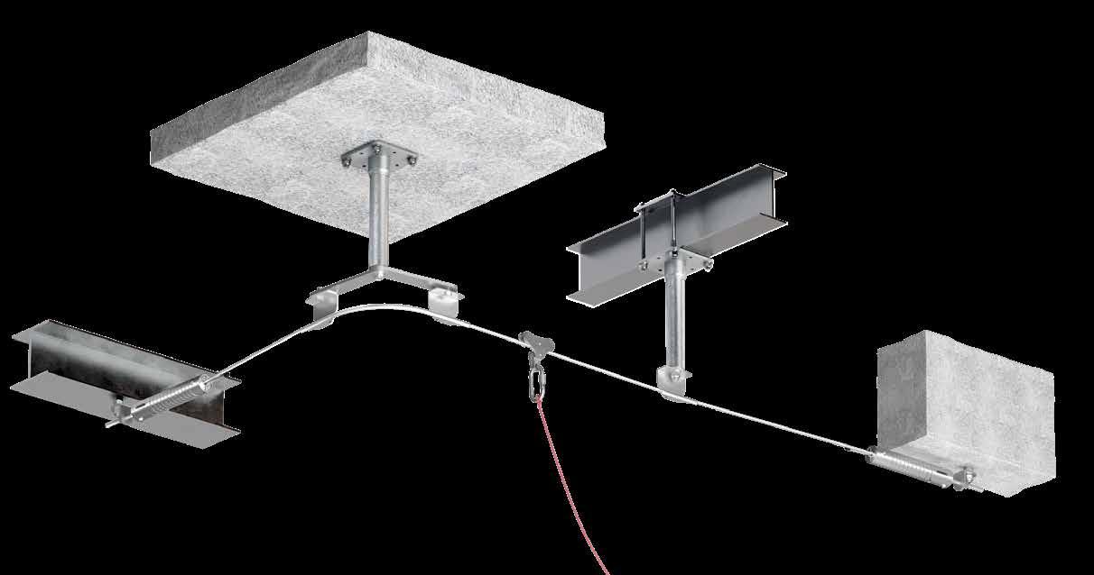
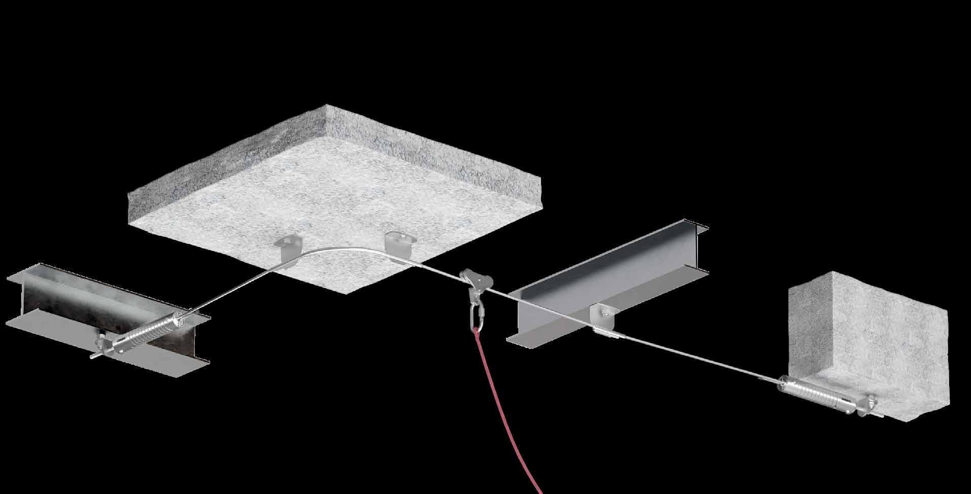
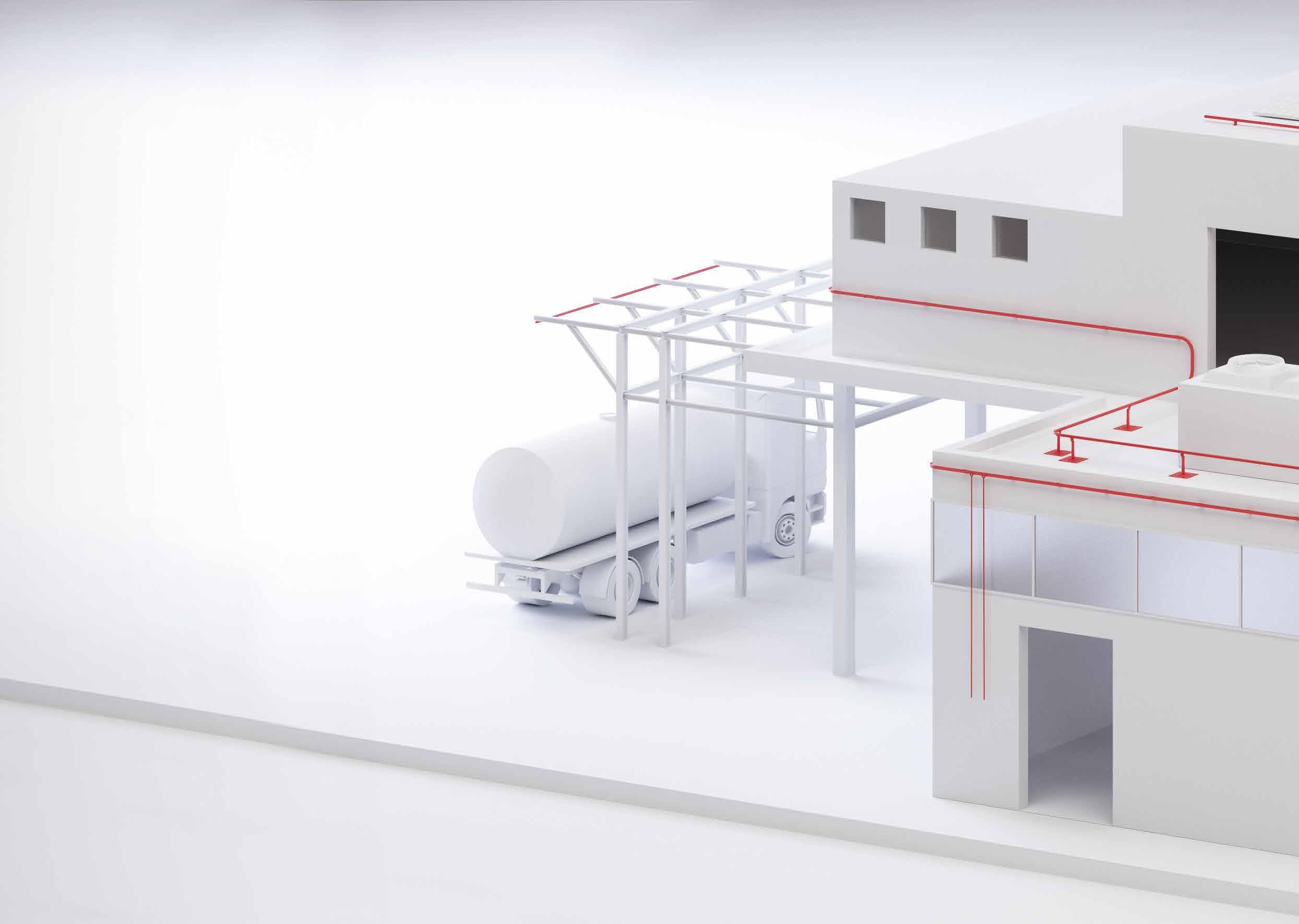
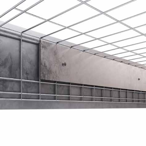
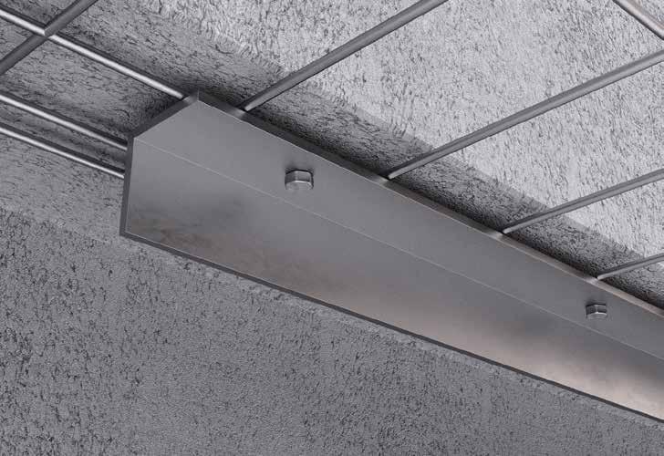
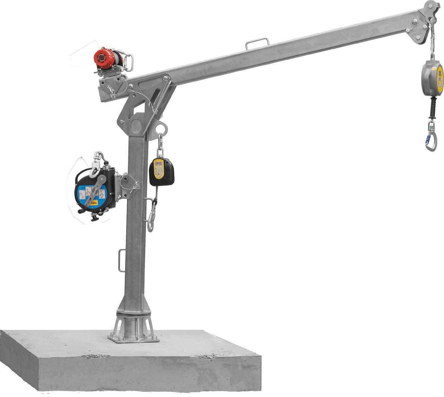
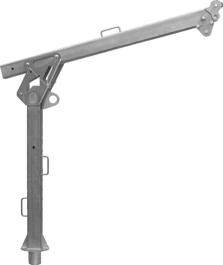
PATROL OVERHEAD
OVERHEAD LIFELINE ON STEEL AND CONCRETE
APPLICATION
Lifeline for aerial applications such as maintenance of coaches, trucks, machinery and aeroplanes.
SAFE
Sliding device that allows operators to pass intermediate elements and curves without ever disengaging from the system.
PRACTICAL
Possibility of anchoring to the upside-down TOWER support to lower the lifeline relative to the ceiling.
Installation of an overhead PATROL lifeline directly on the steel or concrete supporting structure.
/ SPEAR
3 OHANGEXT + ANGSUP / OHANGINT + ANGSUP
4 OHINT 5 OHSLIDE
6 CABLE
TECHNICAL DATA*
substructure minimum thickness fasteners
C20/25 140 mm rod Ø12/Ø16 AB7 M10 VIN
VIN-FIX
HYB-FIX M10 VIN SKR CE
S235JR 5 mm EKS + ULS + MUT EKS M10 +ULS+MUT
* The values indicated are the result of experimental tests carried out under the supervision of third parties in accordance with the standard referred to. For a calculation report with minimum distances according to the relevant standard requirements, the substructure must be checked by a qualified engineer before installation.
PATROLEND | CODES AND DIMENSIONS
PATROLEND AISI
PATROLTERM
COMPLEMENTARY PRODUCTS
CODE description page
For TOWER codes see page 22.
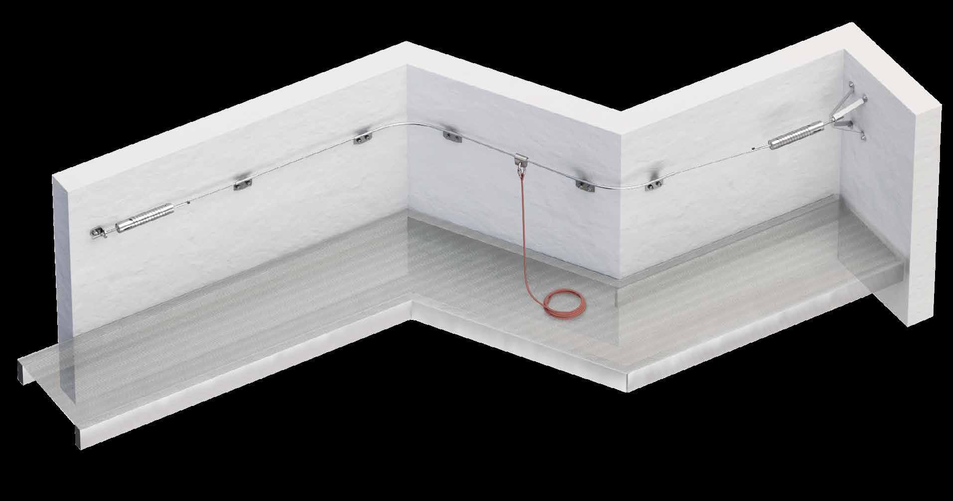
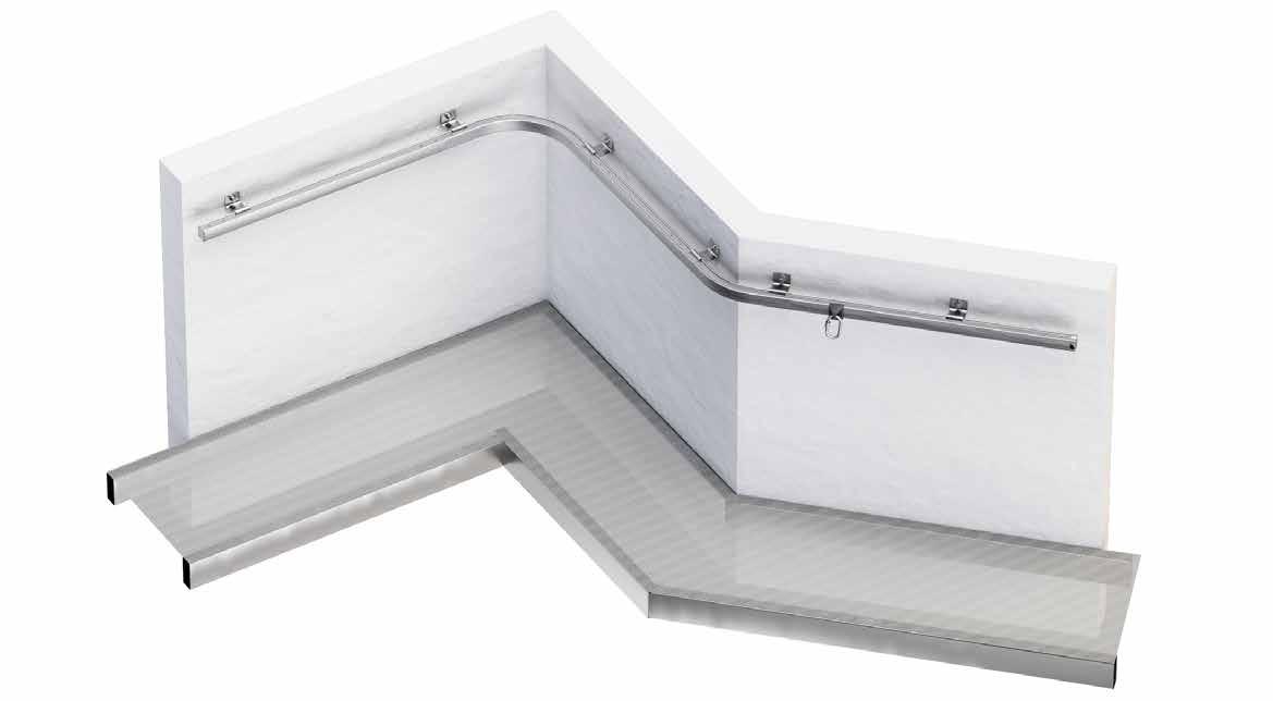
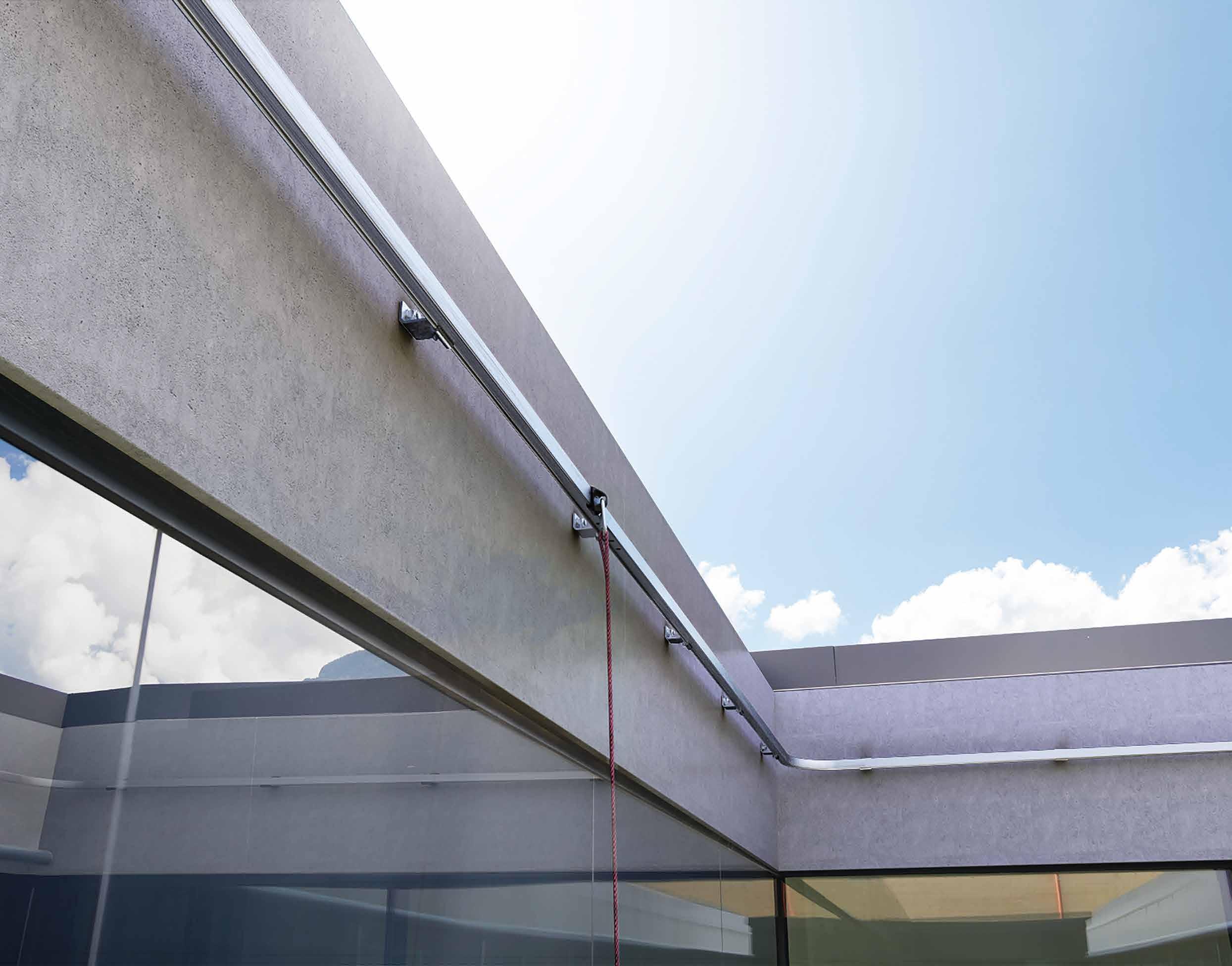
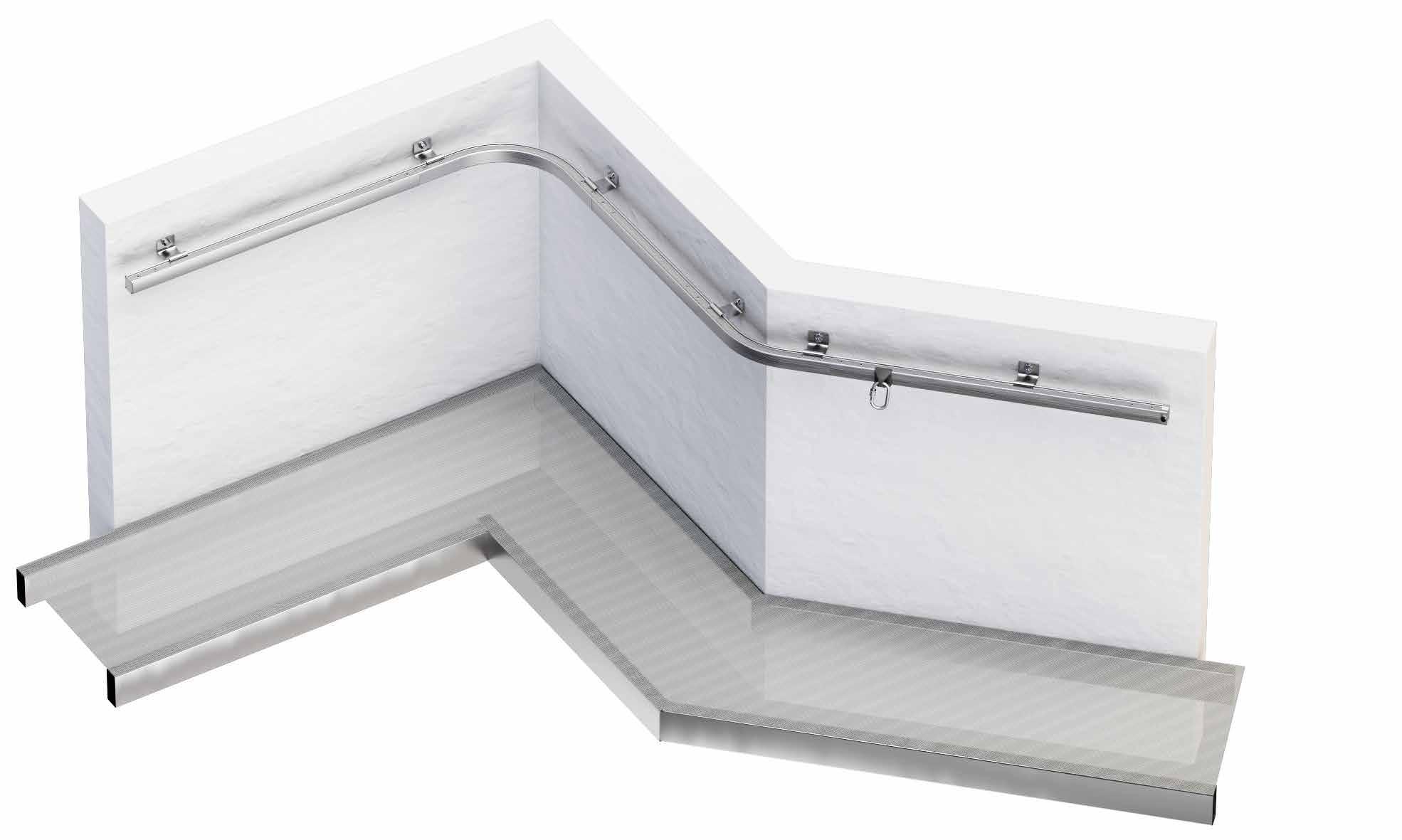
PATROL ON WALL
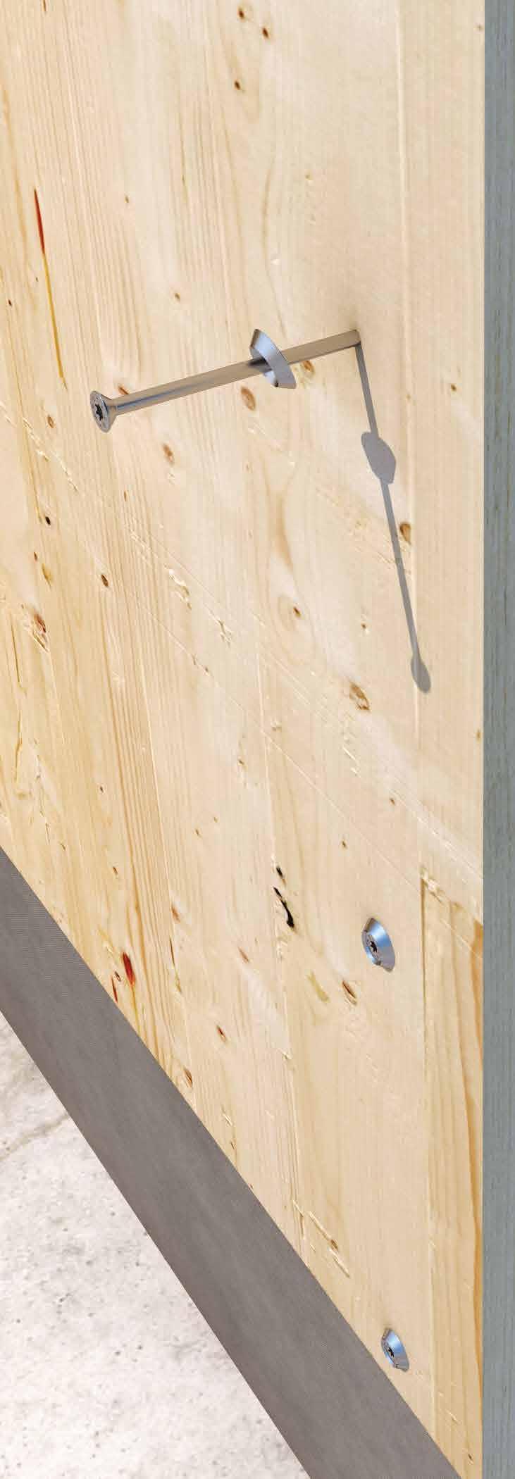
WALL-MOUNTED LIFELINE ON STEEL AND CONCRETE
AESTHETICS
The size of the components minimises the aesthetic impact of the safety device on the roof.
FUNCTIONAL
Thanks to the different components available, it is possible to create lifelines according to site requirements.
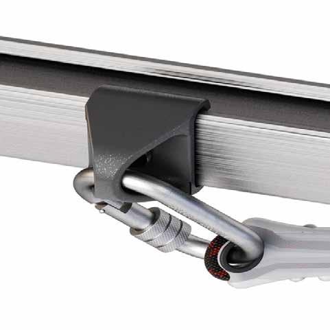
PRACTICAL
Possibility of using components that allow the operator to pass through intermediate points and curves by means of a sliding device.
PATROL lifeline installed on the wall directly on a steel or concrete support structure.
LIFELINE COMPONENTS n. CODE 1 PATROLEND 2 PAREND
3 SPEAREVO / SPEAR
4 PAREXBEND / PAREX 5 PARINTER
6 PARINBEND / PARIN
7 SLIDE 1 / SLIDE 2
8 CABLE
TECHNICAL DATA*
substructure minimum thickness fasteners
C20/25 140 mm rod Ø12/Ø16 AB7 M10 VIN
VIN-FIX HYB-FIX M10 VIN SKR CE
S235JR 5 mm EKS + ULS + MUT EKS M10 +ULS+MUT
* The values indicated are the result of experimental tests carried out under the supervision of third parties in accordance with the standard referred to. For a calculation report with minimum distances according to the relevant standard requirements, the substructure must be checked by a qualified engineer before installation.
PATROLEND | CODES AND DIMENSIONS
COMPLEMENTARY PRODUCTS
CODE description page
PAREX external pass through angle bracket for façades 49
PARIN internal pass through angle bracket for façades 50
PARINTER pass through intermediate element for façades 49
CODE description page
PARINBEND internal pass-through angle bracket for façades adjustable
PAREXBEND external pass-through angle bracket for façades adjustable
50
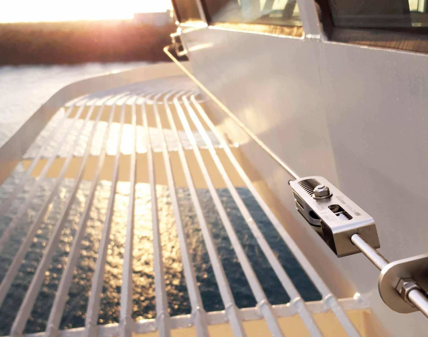
PATROL A4
LIFELINE WITH A4 STAINLESS STEEL COMPONENTS
STRONG
AISI 316 stainless steel elements provide excellent corrosion resistance in marine and industrial environments.
USE
Specially designed shuttles can be used to enable the operator to pass through bends and intermediate points without ever disconnecting.
ASSEMBLY
Quick and easy directly on concrete or steel structure.
PATROL lifeline installed with stainless steel supports on the deck of a ship.
PATROL
PATROL OVERHEAD A4 LIFELINE COMPONENTS
/ SPEARA4
+ ANGSUPA4 / PASANGBENDA4/ PASANGA4
/ SLIDE2A4
PATROL ON WALL A4 LIFELINE COMPONENTS
/ SPEARA4
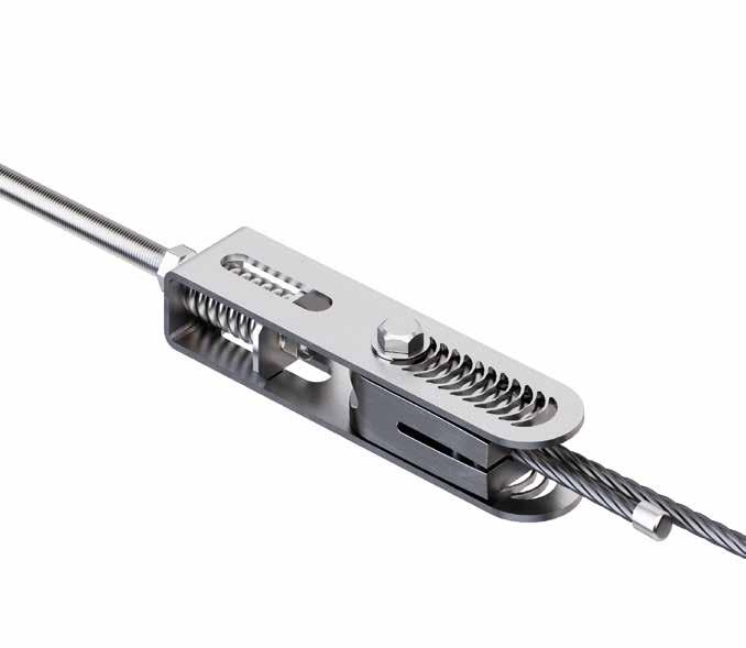
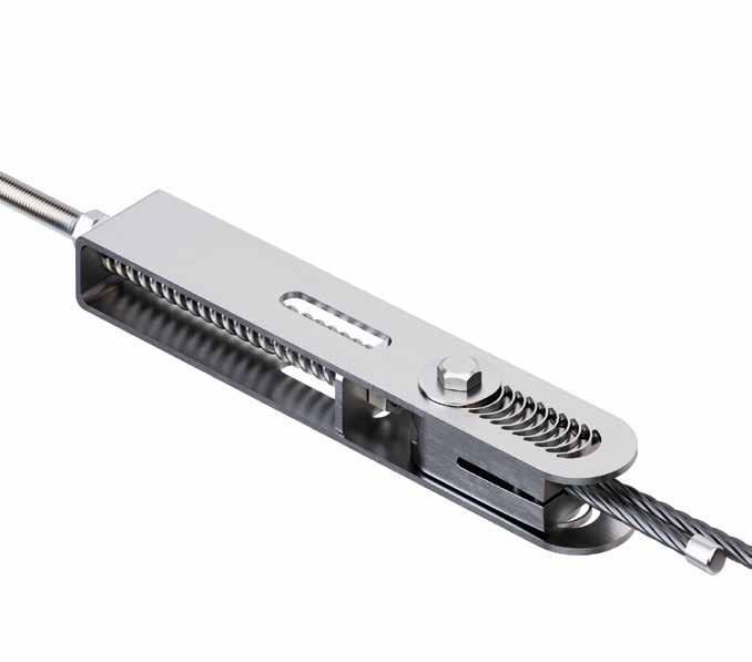
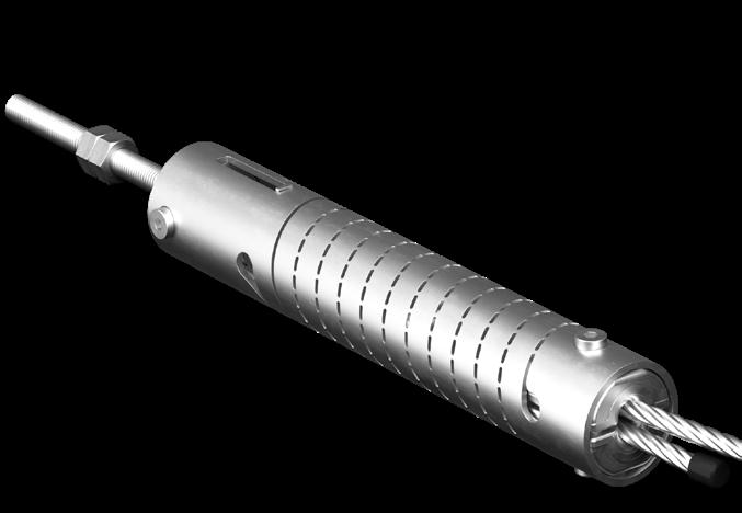
PATROL | components
TERMINAL ELEMENTS | CODES AND DIMENSIONS
TENSIONERS AND ENERGY ABSORBERS | CODES AND DIMENSIONS
INTERMEDIATE ELEMENTS | CODES AND DIMENSIONS
PASINT pass-through intermediate element
PASINTA4 pass-through intermediate element INOX A4
PARINTER pass through intermediate element for façades
PARINTERA4 A4 stainless steel pass through intermediate element for façades
pass-through intermediate element for aerial application in A4
ANGLE BRACKETS | CODES AND DIMENSIONS
PASANG corner pass-through element
stainless steel pass through angle bracket
angle bracket for adjustable supports
PASANGBENDA4
angle bracket for adjustable A4 supports
external pass through angle bracket for façades
external pass through angle bracket for A4 façades
PATROL | components
ANGLE BRACKETS | CODES AND DIMENSIONS
external pass-through angle bracket for A4 façades adjustable 105°-165°
PARIN internal pass through angle bracket for façades
PARINA4 internal pass through angle bracket for A4 façades
angle bracket for façades adjustable 105°-165°
PARINBENDA4 internal pass-through angle bracket for A4 façades adjustable 105°-165°
Internal/external pass through angle bracket for façades. An angle of 165°105° can be adjusted using the BENDTOOL.
FLEXIBLE / ADAPTABLE "BEND" PRODUCTS
PASANGBEND
Adjustable pass-through angle bracket for direct installation. An angle of 165°-105° can be adjusted using the BENDTOOL.
PASANGBEND + ANGSUP
Adjustable pass-through angle bracket for supports. An angle of 165°-105° can be adjusted using the BENDTOOL.
Tool for adjusting the angle of PARINBEND/PAREXBEND/PASANGBEND devices between 165° and 105°.
1. Insert the selected bendable angle element into the BENDTOOL bending device
2. Bend the angle element by levering with the bending device.
3. Remove the angle element from the bending device. The element is ready to be installed.
BENDTOOL
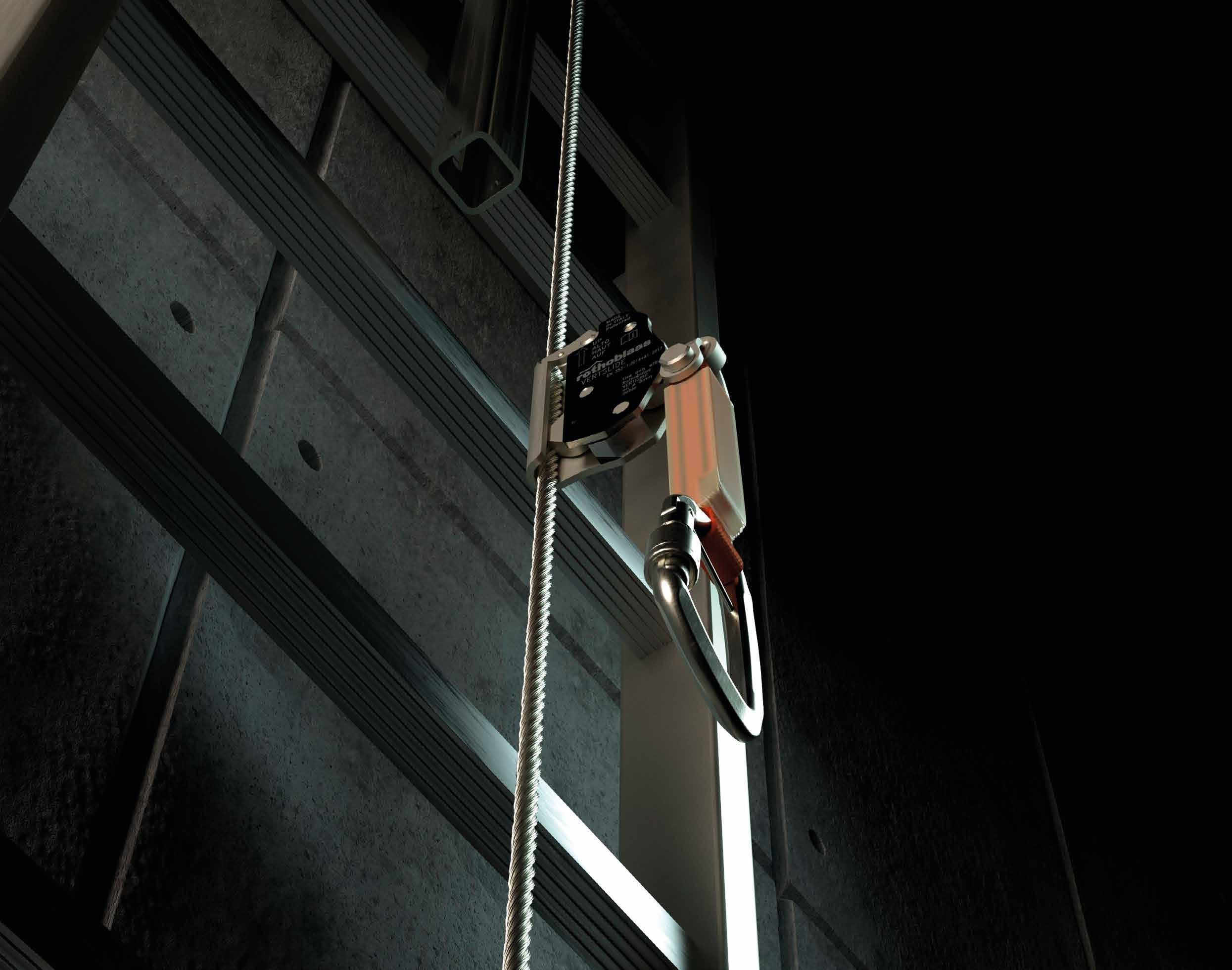
VERTIGRIP
VERTICAL LIFELINE
SIMPLE, MODULAR, DURABLE.
The VERTIGRIP vertical lifeline is the ideal system for ensuring safety on ladders and vertical accesses.
Fast and easy to assemble, installation only takes a few steps. Modular system that can meet any design requirement thanks to the wide range of available accessories offering greater versatility of use. Complete system in AISI 316 stainless steel - AISI 304 stainless steel - EN AW 6082 aluminium alloy, guarantees good corrosion resistance.
VERTIGRIP | overview
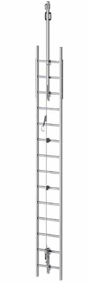
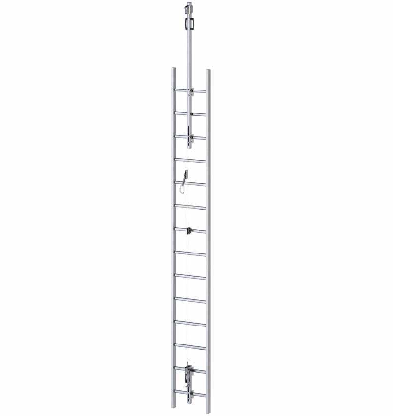
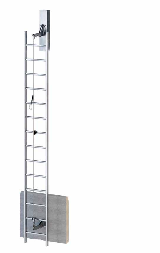
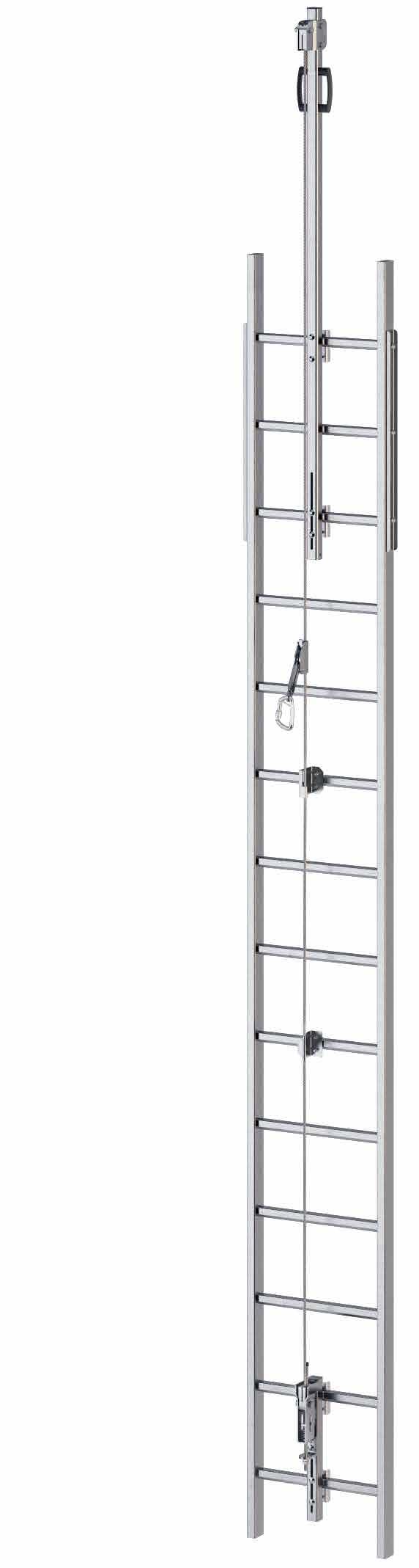
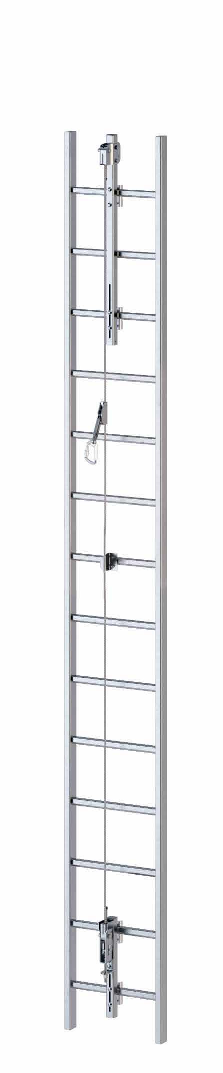
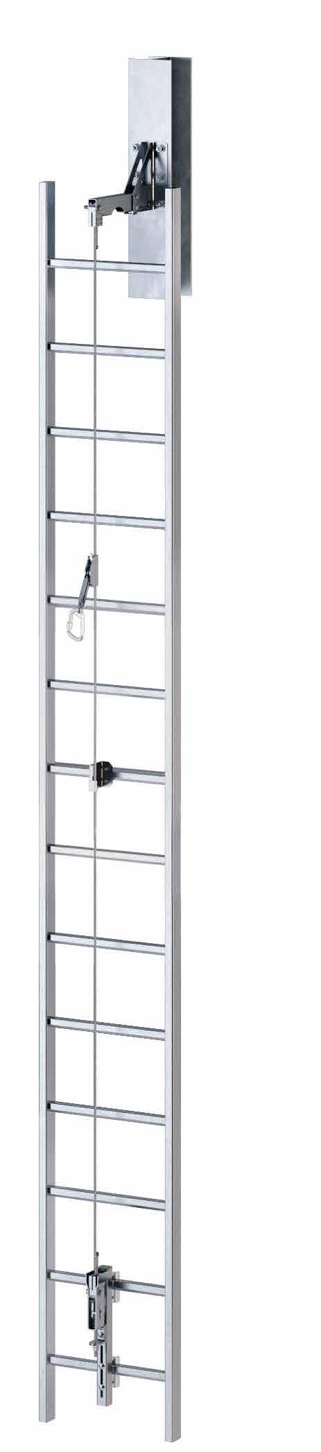
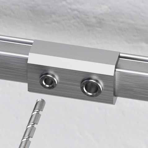
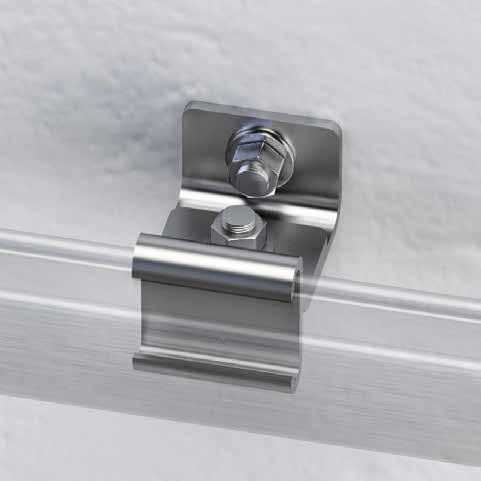
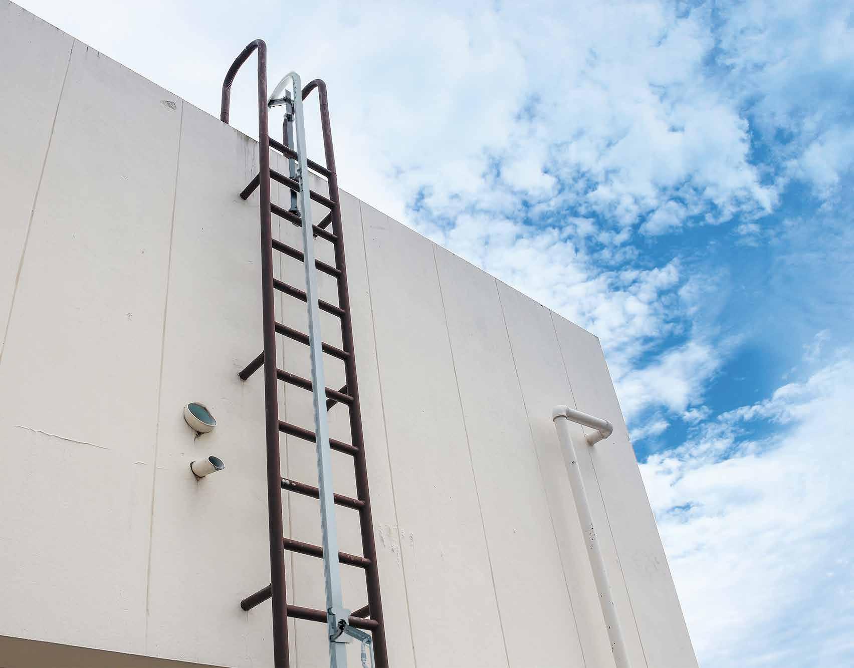
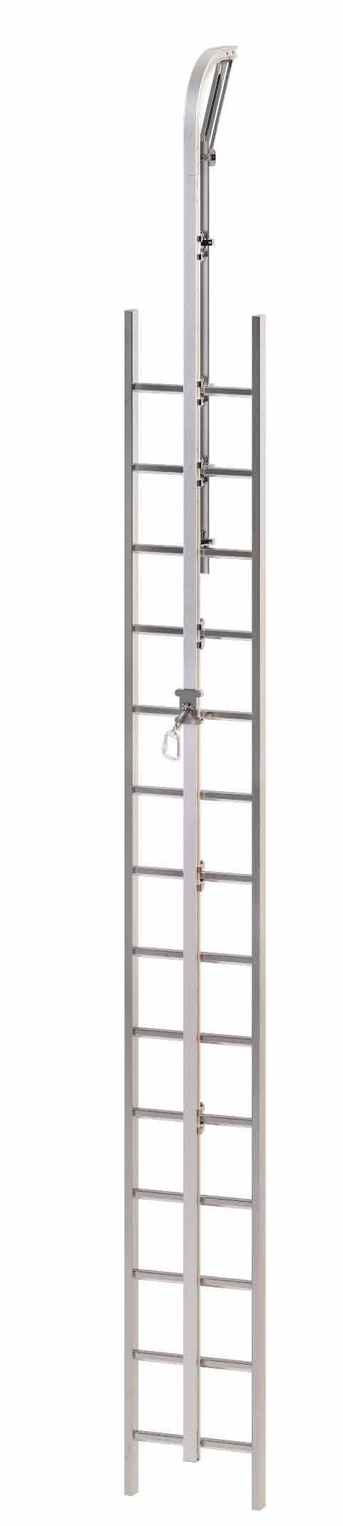
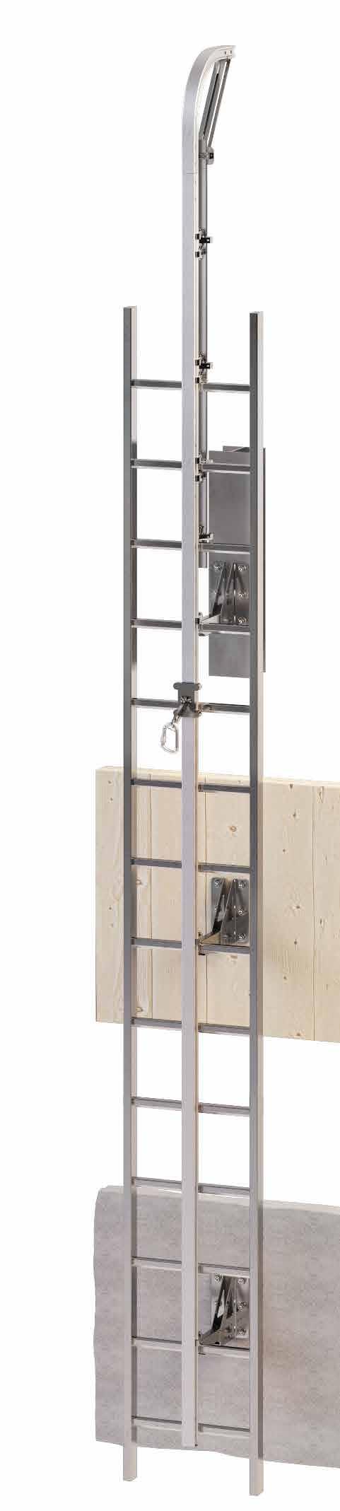
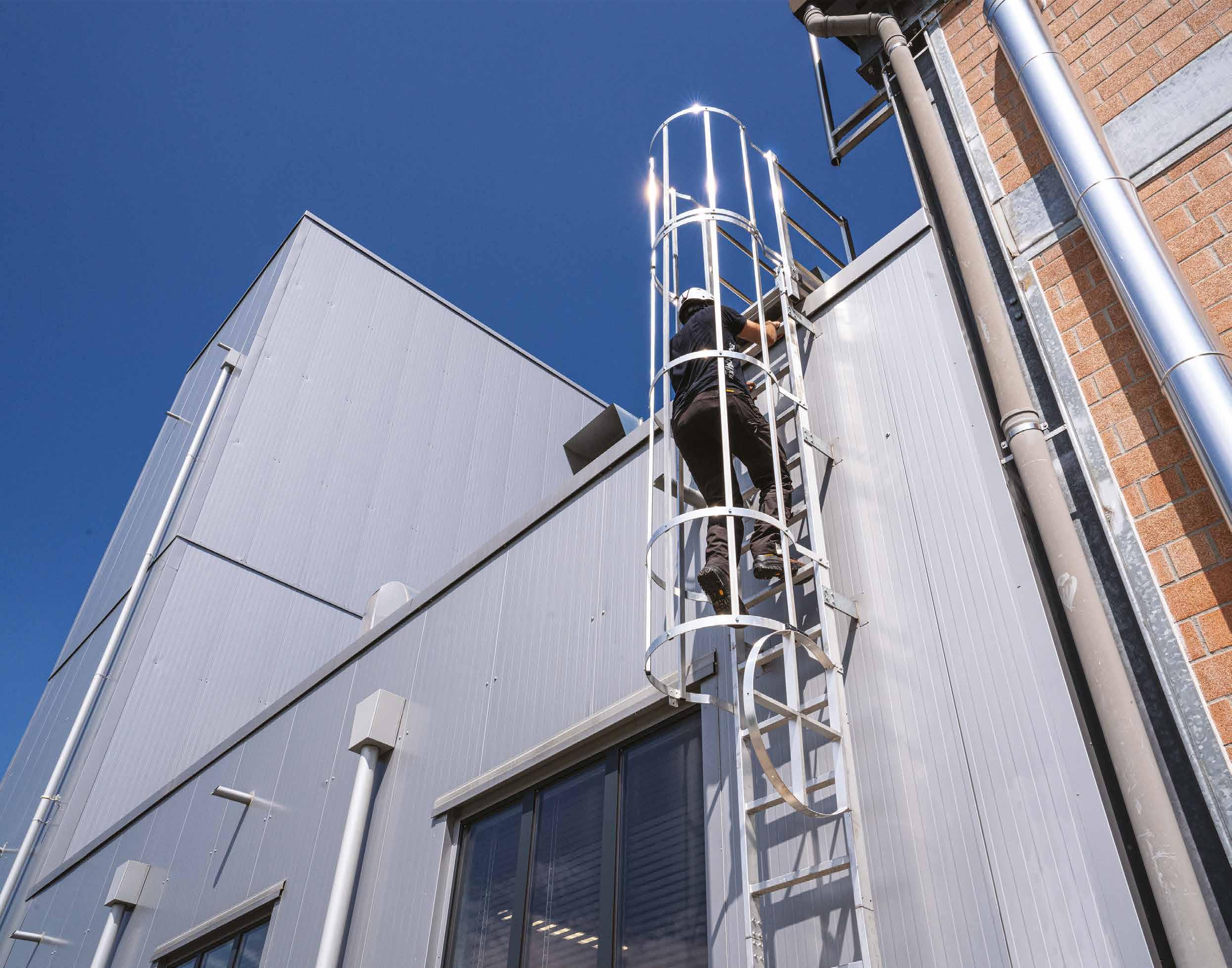
VERTIGRIP ON LADDER
VERTICAL LIFELINE ON LADDERS
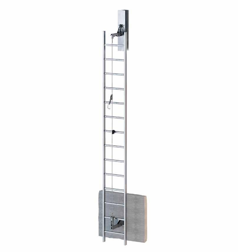
VERTIGRIP ON WALL
VERTICAL LIFELINE ON WALL
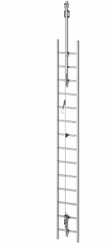
VERTIGRIP A4
VERTICAL LIFELINE WITH A4 STAINLESS STEEL ELEMENTS
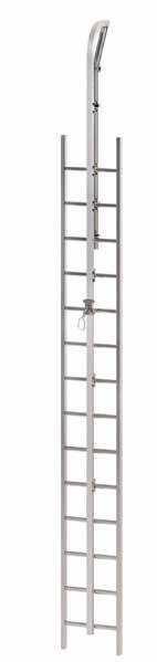
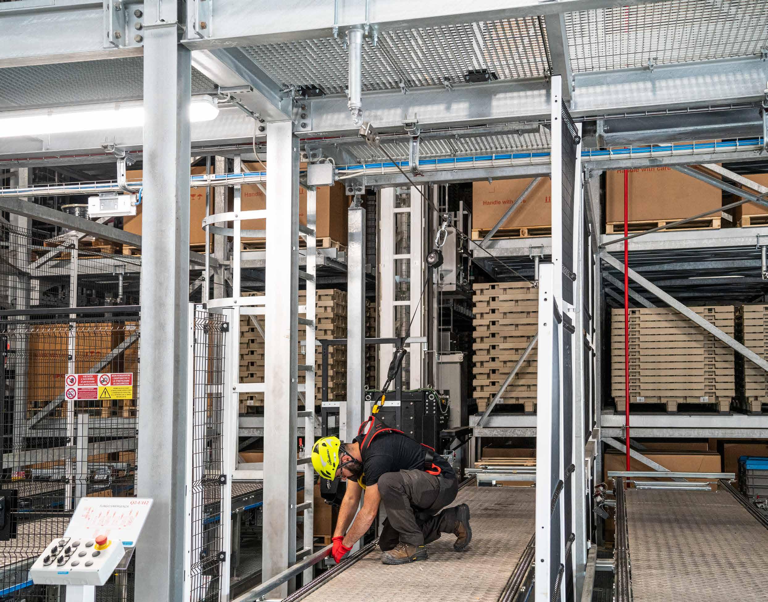
VERTIGRIP ON LADDER
VERTICAL LIFELINE ON LADDERS
QUALITY
Complete system in AISI 316 stainless steel - AISI 304 stainless steel EN AW 6082 aluminium alloy, guarantees excellent corrosion resistance.
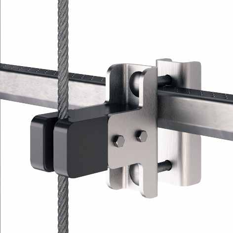
TOTAL CONTROL
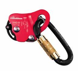
Guided type fall arrester on rope with integrated energy absorber, which allows a controlled ascent and descent in safe conditions.
PRACTICAL
The system can be assembled off-centre on the ladder.
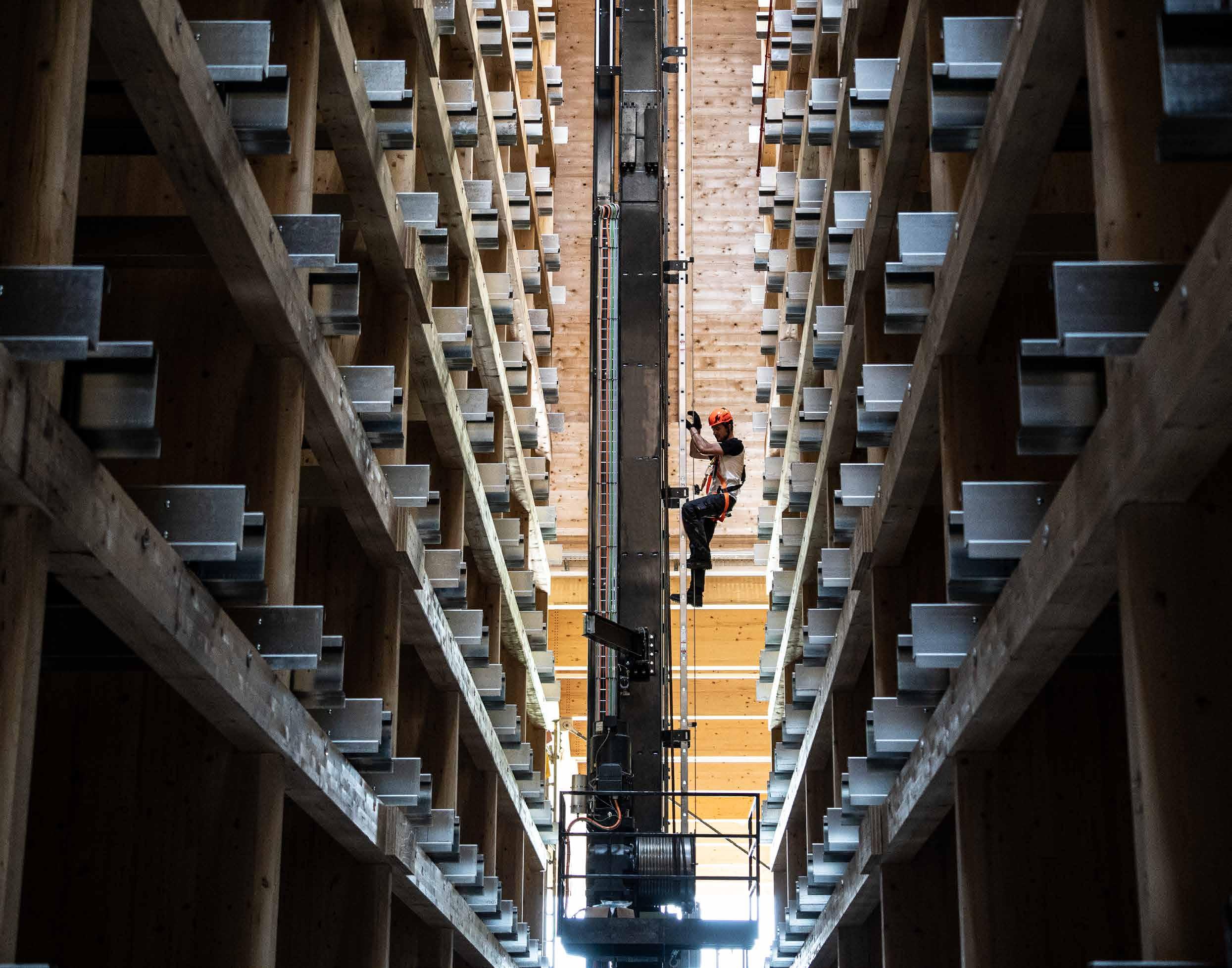
Installation of a VERTIGRIP vertical lifeline on a ladder for maintenance of an automated warehouse.
n. CODE
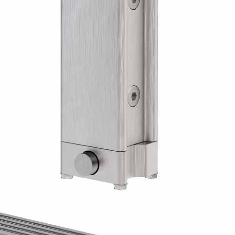
1 VERTBASE
2 VERTSPEAR
3 VERTHAND
4 VERTSUP
5 CABLE
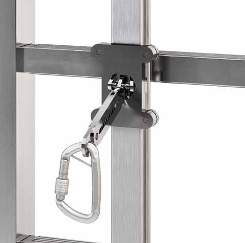
6 VERTINTPAS1 / VERTINTPAS2 / VERTINT
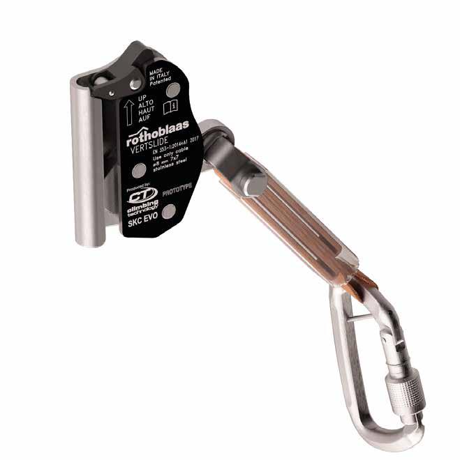
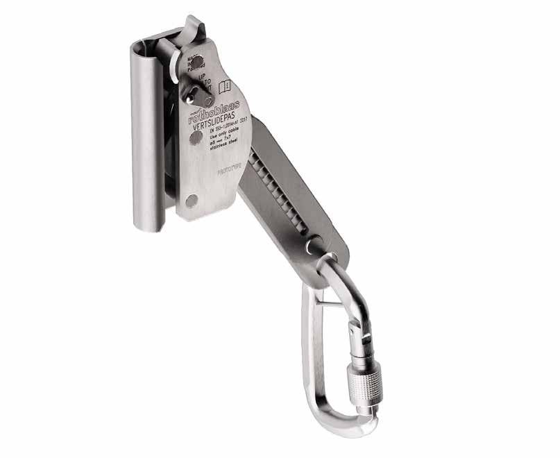
7 VERTSLIDEPAS / VERTSLIDE
8 VERTOP17 / VERTOP09
Vertical Ladder
TECHNICAL DATA*
* The values indicated are the result of experimental tests carried out under the supervision of third parties in accordance with the standard referred to. For a calculation report with minimum distances according to the relevant standard requirements, the substructure must be checked by a qualified engineer before installation.
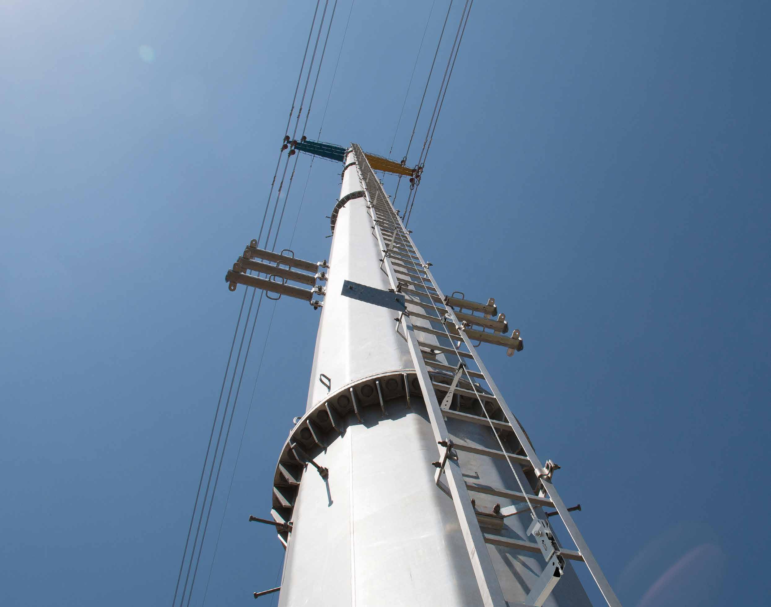
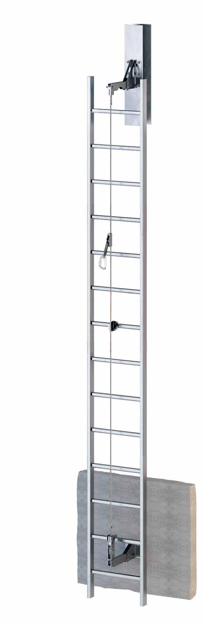
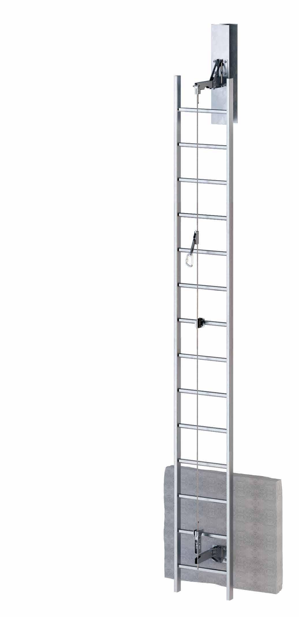
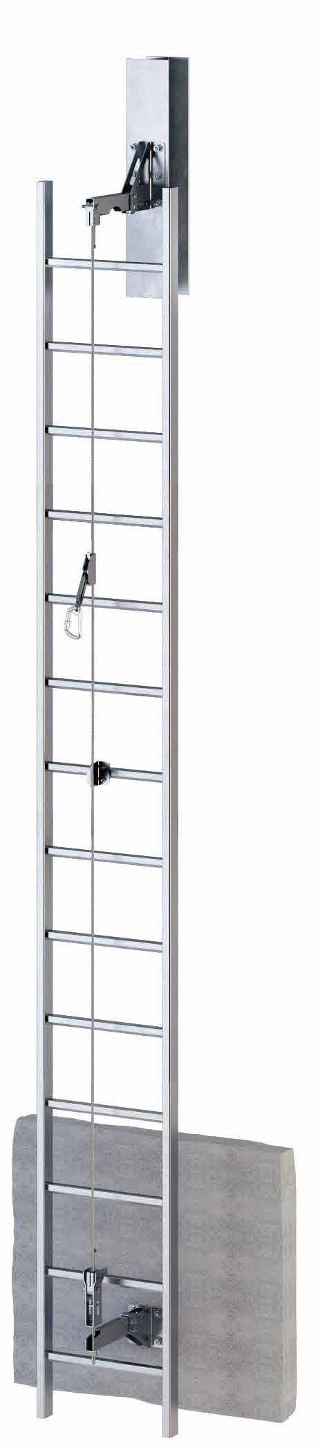
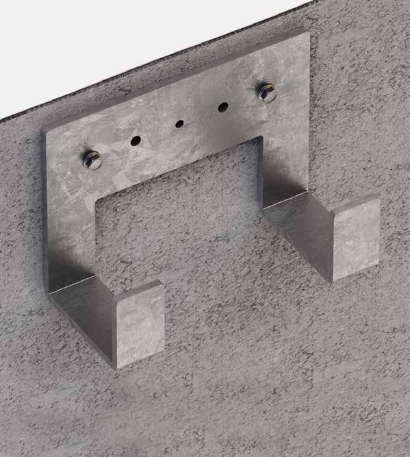
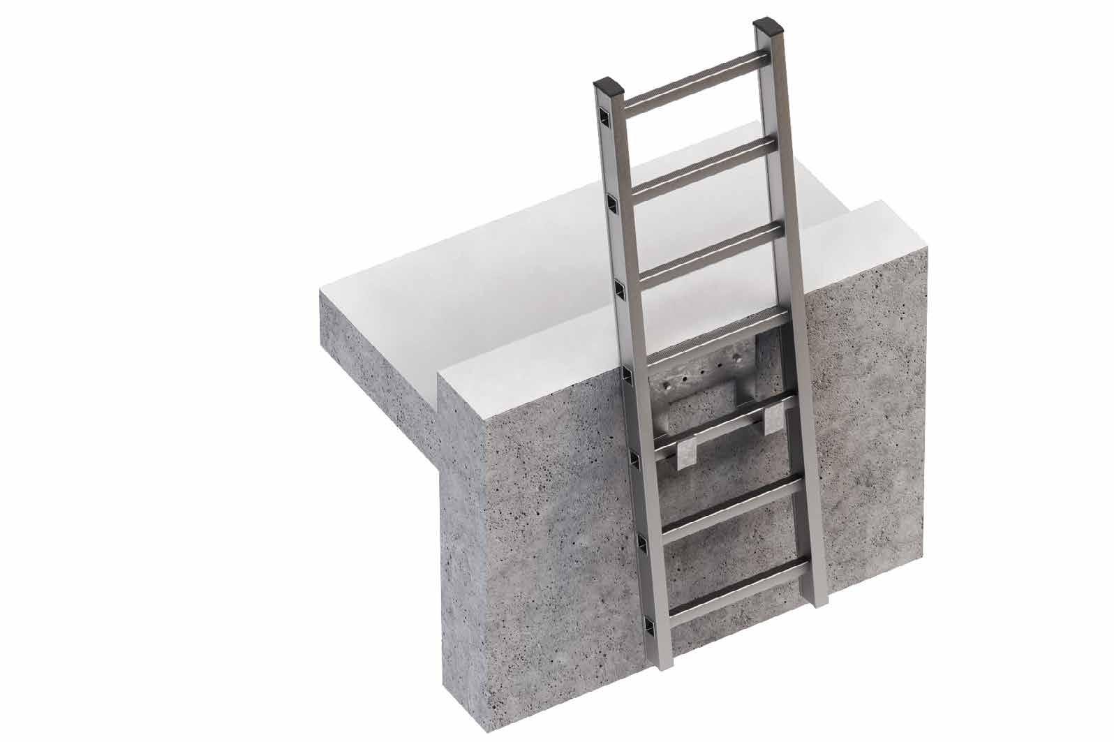
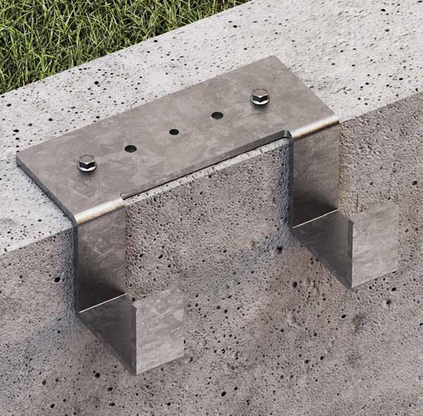
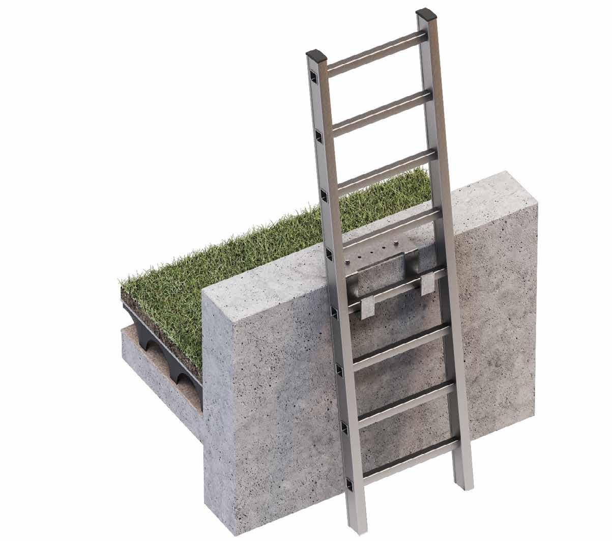
VERTIGRIP ON WALL
VERTICAL LIFELINE ON WALL
ALTERNATIVE
Alternative solution when it is not possible to assemble the vertical lifeline on the ladder.
ADJUSTABLE
Possibility of adjusting the distance of the lifeline from the wall.
FUNCTIONAL
It can be installed on walls inclined at an angle of up to 15° from the vertical.
Installation of VERTIGRIP vertical lifeline on a ladder for maintenance of a
tower.
n. CODE
1 VERTBASEW
2 VERTSPEAR
3 CABLE
4 VERTINTPAS1 / VERTINTPAS1 / VERTINTPAS2
5 VERTSLIDEPAS / VERTSLIDE
6 VERTOPW
7 VERTINTPAS1 / VERTINTPAS2 / VERTINT
TECHNICAL DATA*
substructure minimum thickness fasteners CLT 200 mm VGS Ø9VGS AB7
C20/25 140 mm AB1 Ø12 VGS AB7 M10 rod Ø12 AB7 M10 VIN VIN-FIX
HYB-FIX M10 VIN SKR CE
S235JR 6 mm EKS + ULS + MUT EKS M10 +ULS+MUT
* The values indicated are derived from experimental tests carried out under the supervision of third party organisations according to the referenced standard. For a calculation report with minimum distances, according to the referenced normative requirements, the
installation.
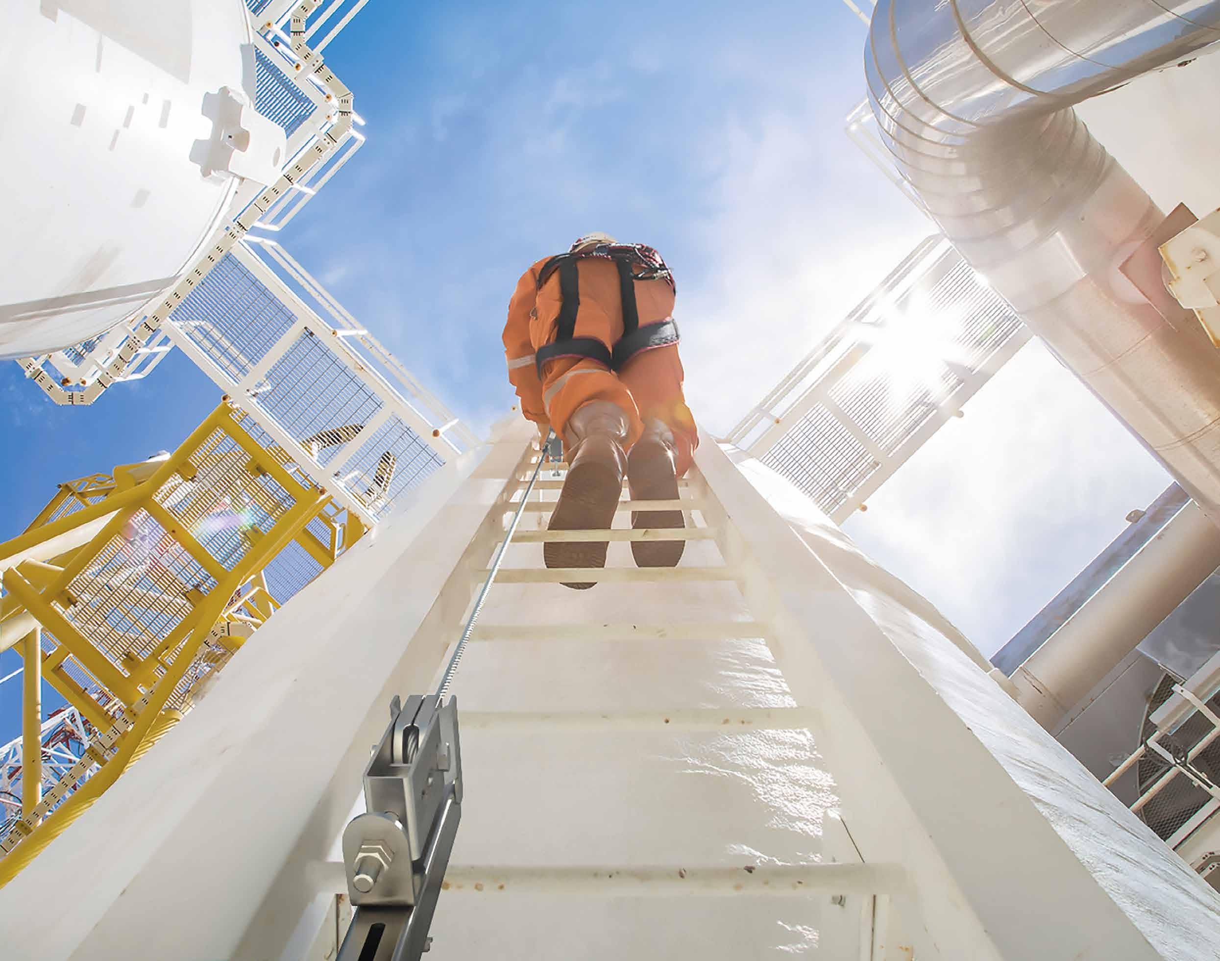
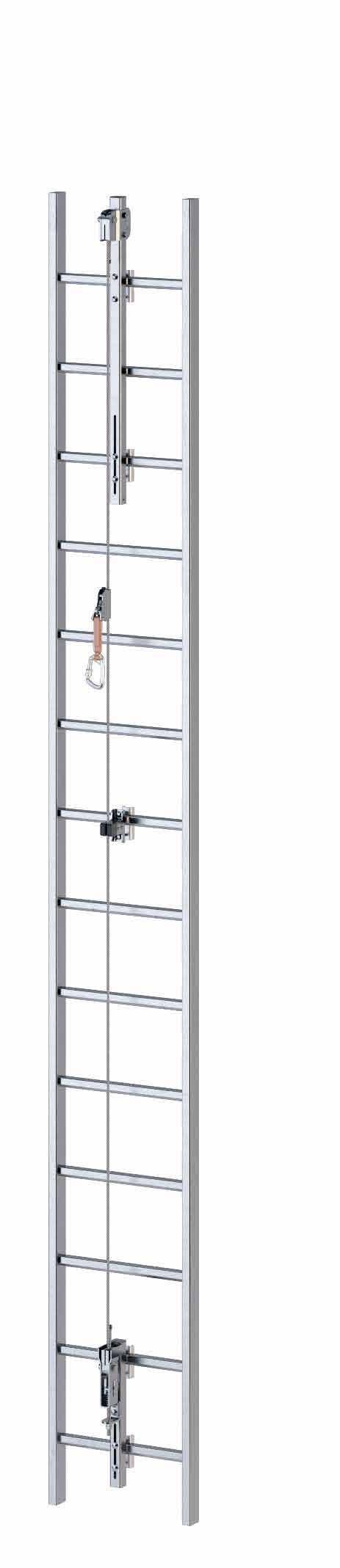
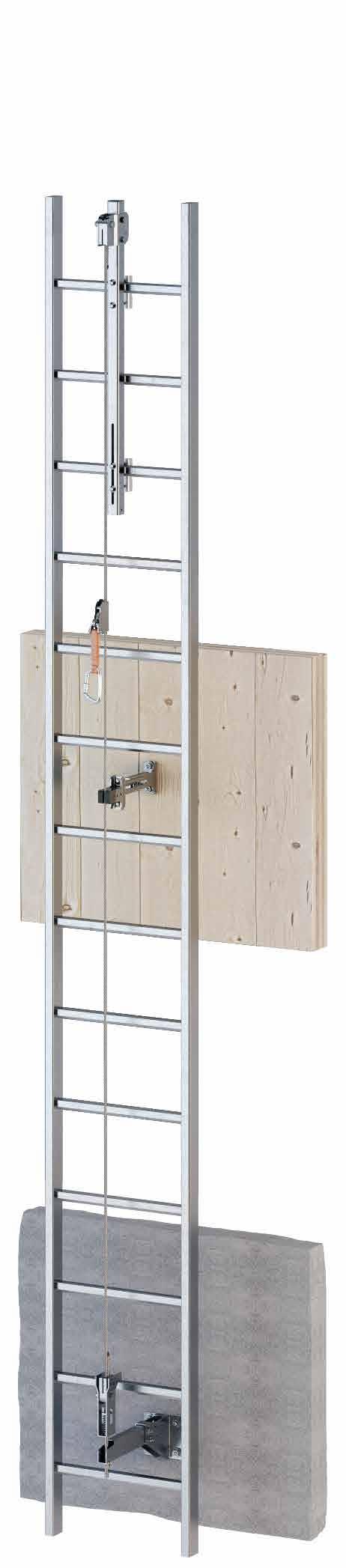
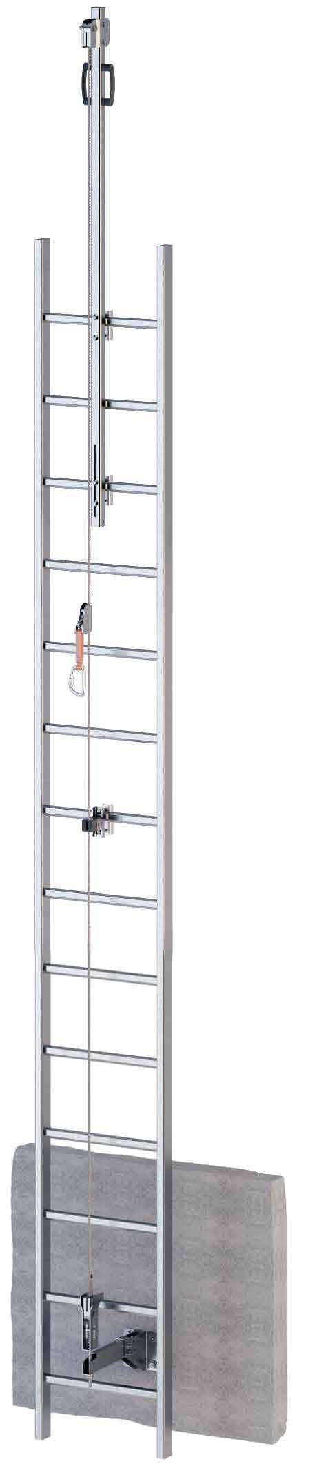
VERTIGRIP A4
VERTICAL LIFELINE WITH A4 STAINLESS STEEL ELEMENTS
STRONG
AISI 316 stainless steel elements provide excellent corrosion resistance in marine and industrial environments.
TOTAL CONTROL
Guided type fall arrester on rope with integrated energy absorber, which allows a controlled ascent and descent in safe conditions.
FUNCTIONAL
It can be installed on walls inclined at an angle of up to 15° from the vertical.
Installation of VERTIGRIP A4 vertical lifeline on a ladder for maintenance of an offshore installation.
VERTICAL LIFELINE COMPONENTS
n. CODE
1 VERTBASEA4
2 VERTSPEARA4
3 VERTINTPAS1A4 / VERTINTA4 / VERTINTPAS2A4
4 VERTSLIDEPAS / VERTSLIDE
5 VERTOP09A4
6 CABLE
TECHNICAL DATA
For technical data, please refer to the VERTIGRIP ON LADDER page 56.
VERTINTPAS1A4 fixed pass-through intermediate element for vertical A4 lifeline AISI 316 stainless steel grade 1.4401
VERTINTPAS2 removable pass-through intermediate element for vertical lifeline AISI 304 stainless steel grade 1.4301
VERTINTPAS2A4 removable pass-through intermediate element for vertical A4 lifeline AISI 316 stainless steel grade 1.4401
*Recommended every 5 meters.
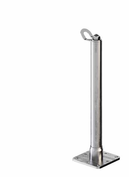
SUPPORT FOR VERTICAL LIFELINE ON STRUCTURE
GROUP
VERTOPW
UPPER ANCHOR SYSTEM
VERTOPWA4
upper anchor system for vertical lifeline on structure stainless steel 1.4301 / AISI 304 5,17 1
upper anchor system for vertical lifeline on A4 structure AISI 316 stainless steel grade 1.4401
Vertbase
1
Vertint
1
Vertop09
1
1
Vertopwall
LOWER ANCHOR SYSTEM
VERTBASEW lower anchor system for vertical lifeline on structure stainless steel 1.4301 / AISI 304 4,52 1 Vertbasewall
VERTBASEWA4
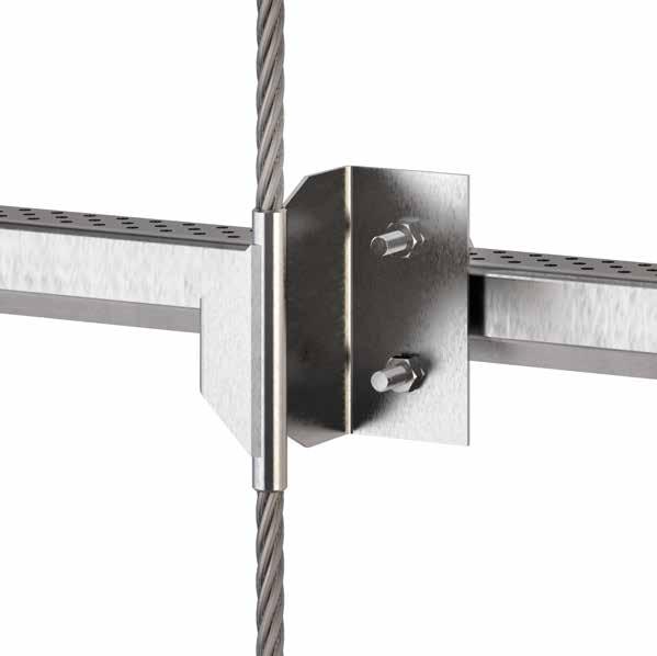
VERTINTW
INTERMEDIATE BRACKET*
VERTINTWA4
*Recommended every 5 meters.
lower anchor system for vertical lifeline on A4 structure AISI 316 stainless steel grade 1.4401
intermediate bracket for vertical lifeline on structure stainless steel 1.4301 / AISI 304 - ABS 1,52 1
intermediate anchor system for vertical lifeline on A4 structure AISI 316 stainless steel grade 1.4401 - ABS
Vertintwall
Vertbasewall
VERTINTPAS1
VERTINTPAS2
VERTIGRIP | components
VERTICAL LIFELINE ACCESSORIES
LADDER
VERTIGRIP | sliding devices
VERTSLIDE
Removable guided type fall arrester with energy absorber for vertical lifeline.
technical features
VERTSLIDEPAS
Removable sliding through fall arrest device with energy absorber for vertical lifeline.
VERTSLIDE VERTSLIDEPAS
standard EN 353-1:2014 + A1:2017 EN 353-1:2014 + A1:2017 absorber fabric stainless steel types semi - pass-through through
VERTIGRIP | ELEMENTS AND INTERMEDIATE ELEMENTS
VERTINTPAS1
Fixed pass-through intermediate element for vertical lifeline.
VERTINTPAS2
Removable intermediate element for vertical lifeline.
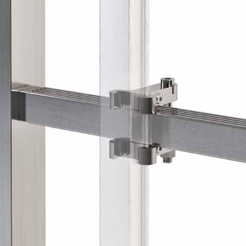
VERTINT
Intermediate bracket for vertical lifeline on ladder.
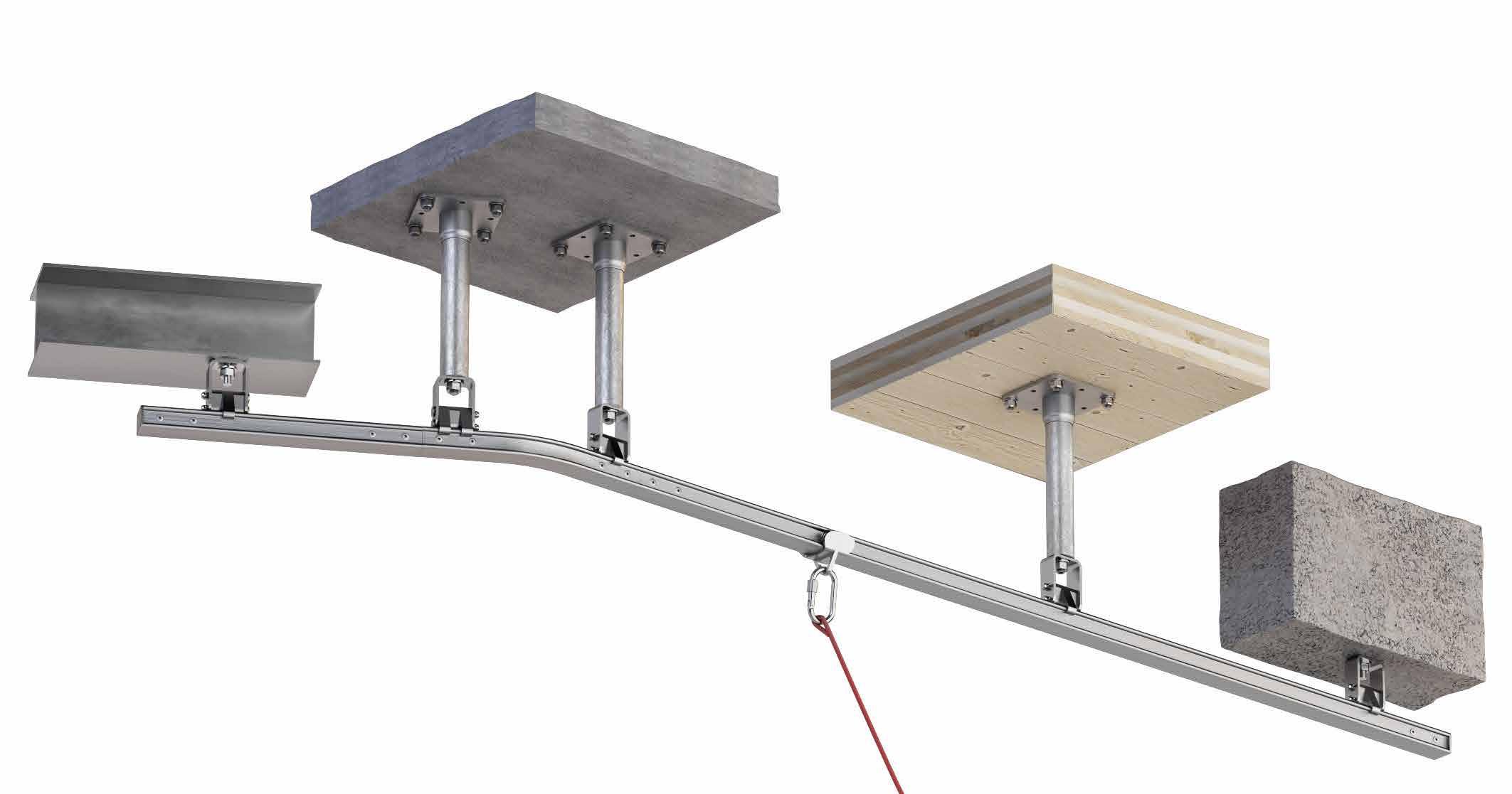
RAIL SYSTEM OVERVIEW
Rigid pass-through LIFELINE for horizontal use for direct application with or without metal brackets on different types of substructure. The accessories allow the rigid LIFELINE to be conformed to the structure on which it is assembled.
Possible use of detachable sliding device along the whole system.
Rigid pass-through LIFELINE for horizontal use with TOWER bracket application, for assembly on various types of substructure. Ideal for elevated installation for overcoming obstacles.
Rigid pass-through LIFELINE for direct application with or without metal brackets on different types of substructure. Ideal for carrying out operations in special conditions, such as working on tanks, tankers, unsafe walkways and other potentially dangerous situations. Equipped with a sliding device with wheels for optimal sliding on the rail.
Rigid pass-through life line for horizontal use for direct application with or without metal brackets on different types of structure. Sliding device suitable for assembled rail with both vertical and horizontal fastening.
Rigid pass-through life line for vertical use for direct application on different types of substructure or for application with metal brackets on the rungs of fixed ladders. Equipped with a sliding device to lock immediately if the operator falls.
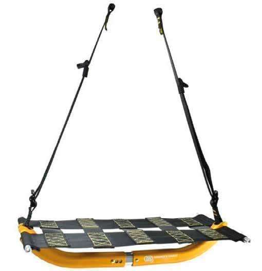
Rigid pass-through life line for use in suspension for direct application with metal brackets on different types of substructure. The sliding device is designed to facilitate the movement of the operator during suspended work, ensuring comfort of use.
H-RAIL
HORIZONTAL RAIL SYSTEM
TO ALWAYS WORK ON THE RIGHT RAIL.
The H-RAIL rail LIFELINE system is safe and versatile. It is possible to create horizontal rigid LIFELINEs, using only a few fasteners, and thanks to the modularity of the system it is possible to create curved or straight rigid LIFELINEs. H-RAIL is also suitable for suspended work on building façades. The three sliding devices available meet different needs: choose the one that suits you and operate safely with H-RAIL!
H-RAIL | overview
H-RAIL ON FLOOR
HORIZONTAL RAIL SYSTEM
H-RAIL + TOWER
HORIZONTAL RAIL SYSTEM ON SUPPORTS PAGE 72
EN
74
H-RAIL OVERHEAD
HORIZONTAL OVERHEAD RAIL SYSTEM
H-RAIL ON WALL
HORIZONTAL WALL-MOUNTED RAIL SYSTEM
EN 795:2012 D CEN/TS 16415:2013 CEN/TS 16415:2013
78
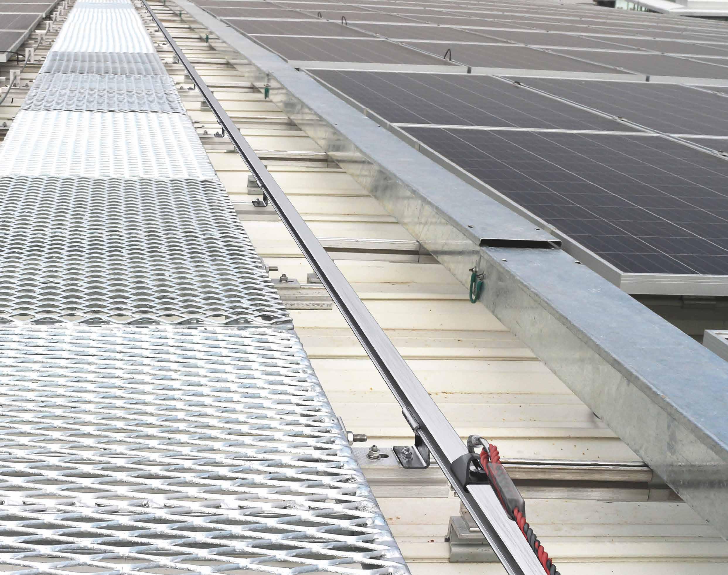
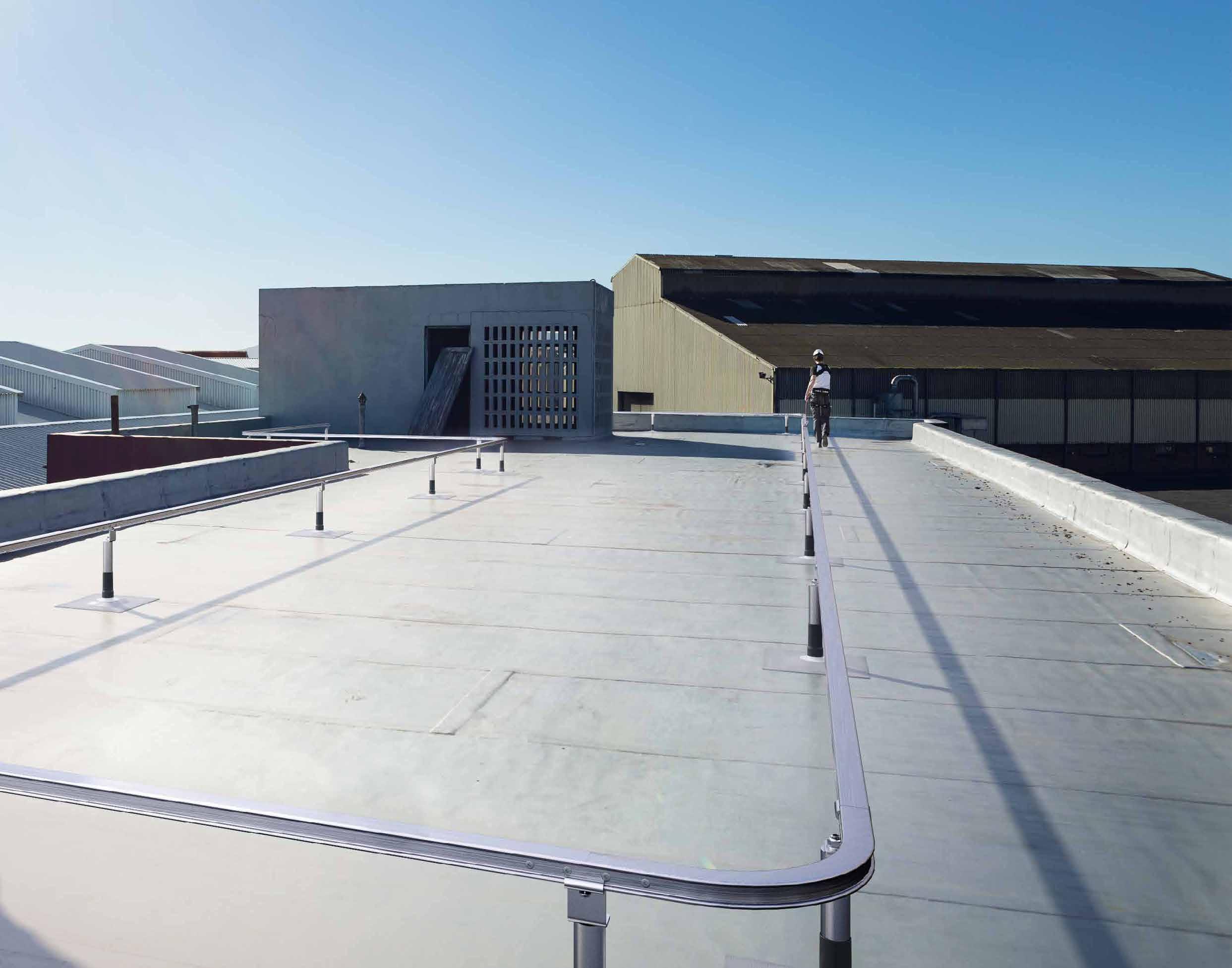
H-RAIL ON FLOOR
HORIZONTAL RAIL SYSTEM
UNOBTRUSIVE
The rail ensures a small footprint on the cover and thus a minimal visual impact.
COMPLETE
The system can be used for different applications (horizontal, vertical and overhead) by using the specific sliding devices.
FAST INSTALLATION
Thanks to the large centre distance between the rail fasteners (6 m), assembly requires a limited number of fastening points.
Installation of H-RAIL rail on flat roof for use as a walkway for the maintenance of a photovoltaic system.
n. CODE
1 RAILEND / RAILENDOPEN
2 RAILBRA / RAILBRAT + RAILBRA12
3 RAILC90 / RAILC120 / RAIL135 / RAILC150
4 RAILSLIDE / RAILSLIDEOPEN
5 RAILJUN
6 RAIL3000
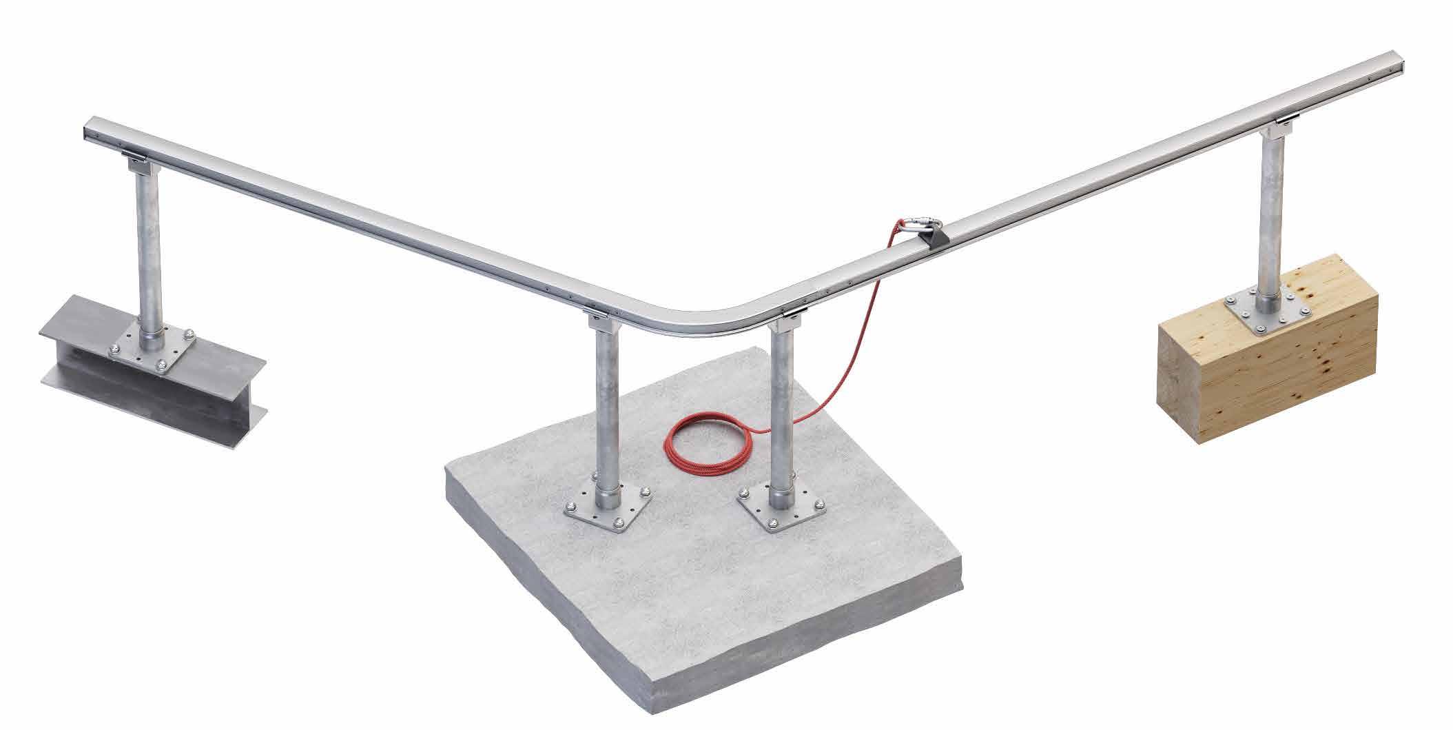
TECHNICAL DATA*
fastening
substructure minimum thickness direct with RAILBRA
GL24h 100 mm VGS Ø11 HBS12
CLT 100 mm VGS Ø11 HBS12
C20/25 140 mm AB1 SKS10
S235JR 6 mm EKS10 EKS10
* The values indicated are the result of experimental tests carried out under the supervision of third parties in accordance with the standard referred to. For a calculation report with minimum distances according to the relevant standard requirements, the substructure must be checked by a qualified engineer before installation.
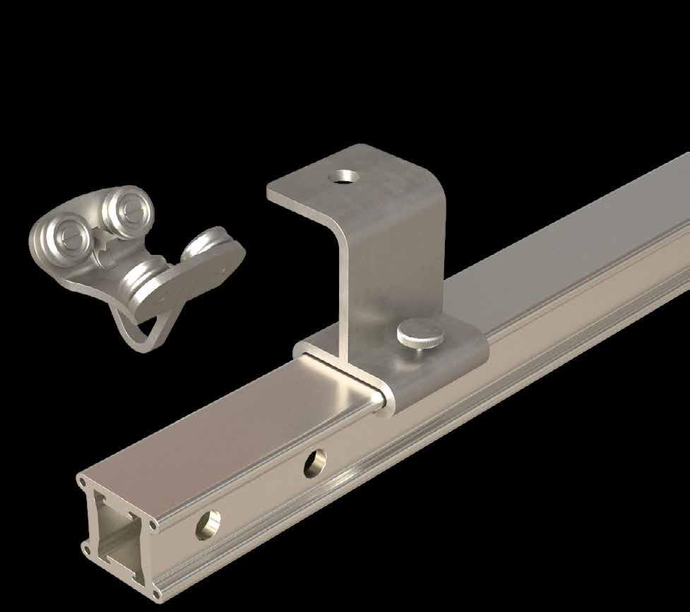
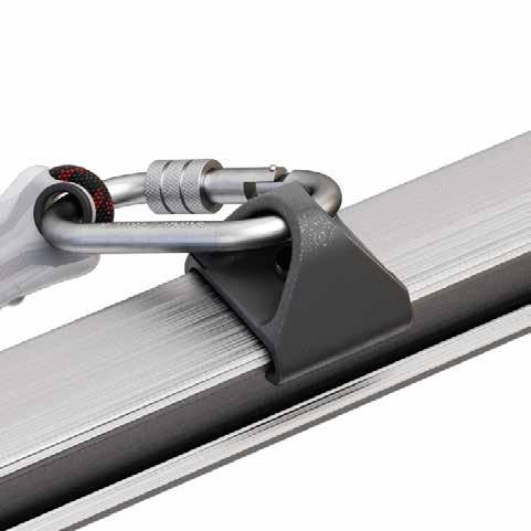
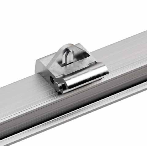
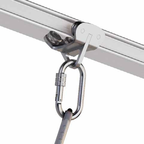
RAILSLIDE
Universal sliding device for rail. Its shape ensures excellent sliding. With locking screw included. Anchorage point also suitable for large connectors.
RAILENDOPEN
Openable end stop, allowing entry and exit from the system.
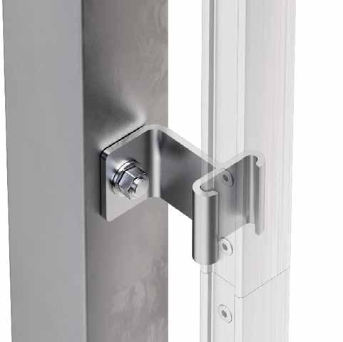
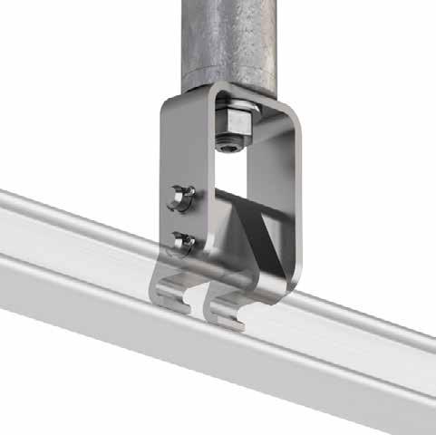
RAILBRA
Universal support for maximum versatility and convenience in mounting on different substrates.
RAIL3000
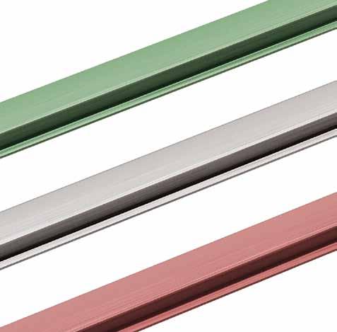
Available in various RAL colours on request.
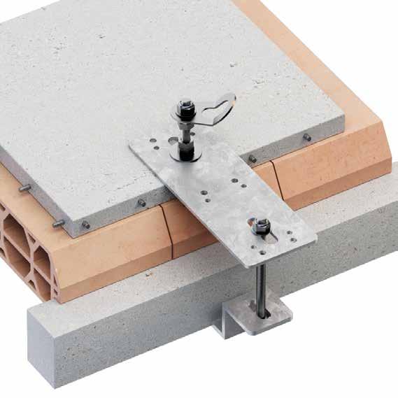
H-RAIL + TOWER
HORIZONTAL RAIL SYSTEM ON SUPPORTS
COMBINABLE
It can be assembled in combination with all TOWER brackets.
FUNCTIONAL
The combination with TOWER supports gives the possibility to raise the rail to overcome obstacles in the roof.
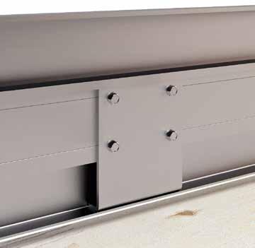
EASY
The rail is simply mounted on the TOWER brackets using the dedicated plate.
Installation of H-RAIL rail with TOWER supports on a flat, insulated concrete roof.
* The values indicated are the result of experimental tests carried out under the supervision of third parties in accordance with the standard referred to. For a calculation report with minimum distances according to the relevant standard requirements, the substructure must be checked by a qualified engineer before installation.
RAILSLIDEOPEN
Openable sliding device. It can be installed and removed in any position on the rail.
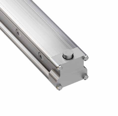
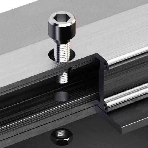
RAILJUN
Universal rail joint. Simple to install. Complete with fastening screws.
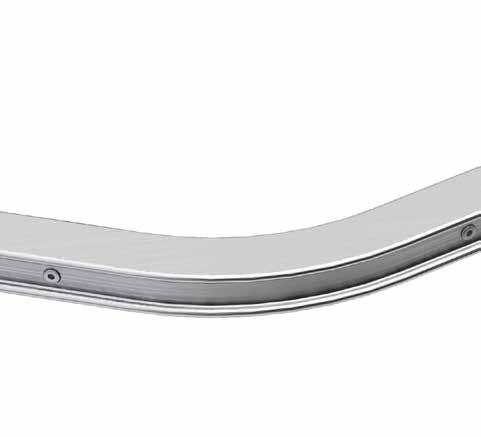
RAILC120, RAILC135, RAILC150
H-RAIL includes bends with different angles to meet specific site requirements.
RAILJUNTOOL
Jig for drilling joint holes for rails cut to size on site.
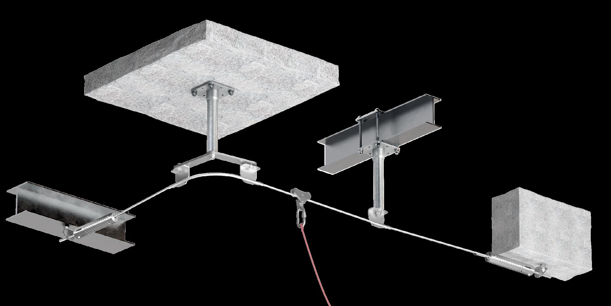
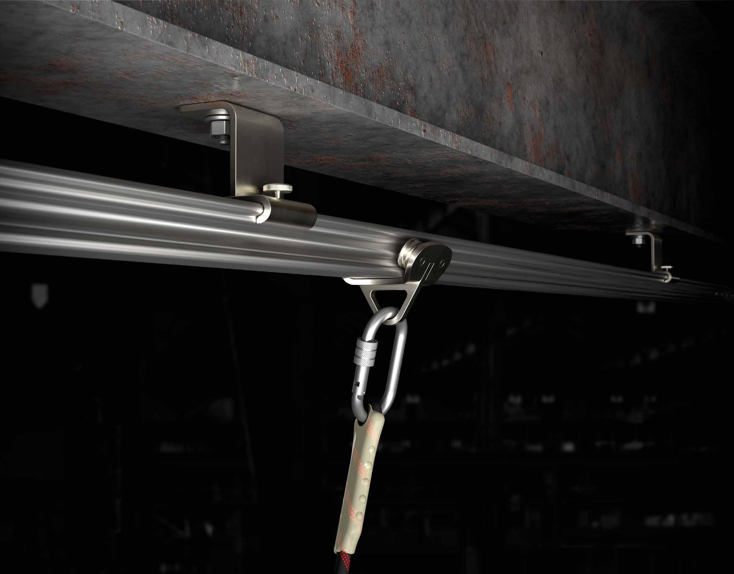
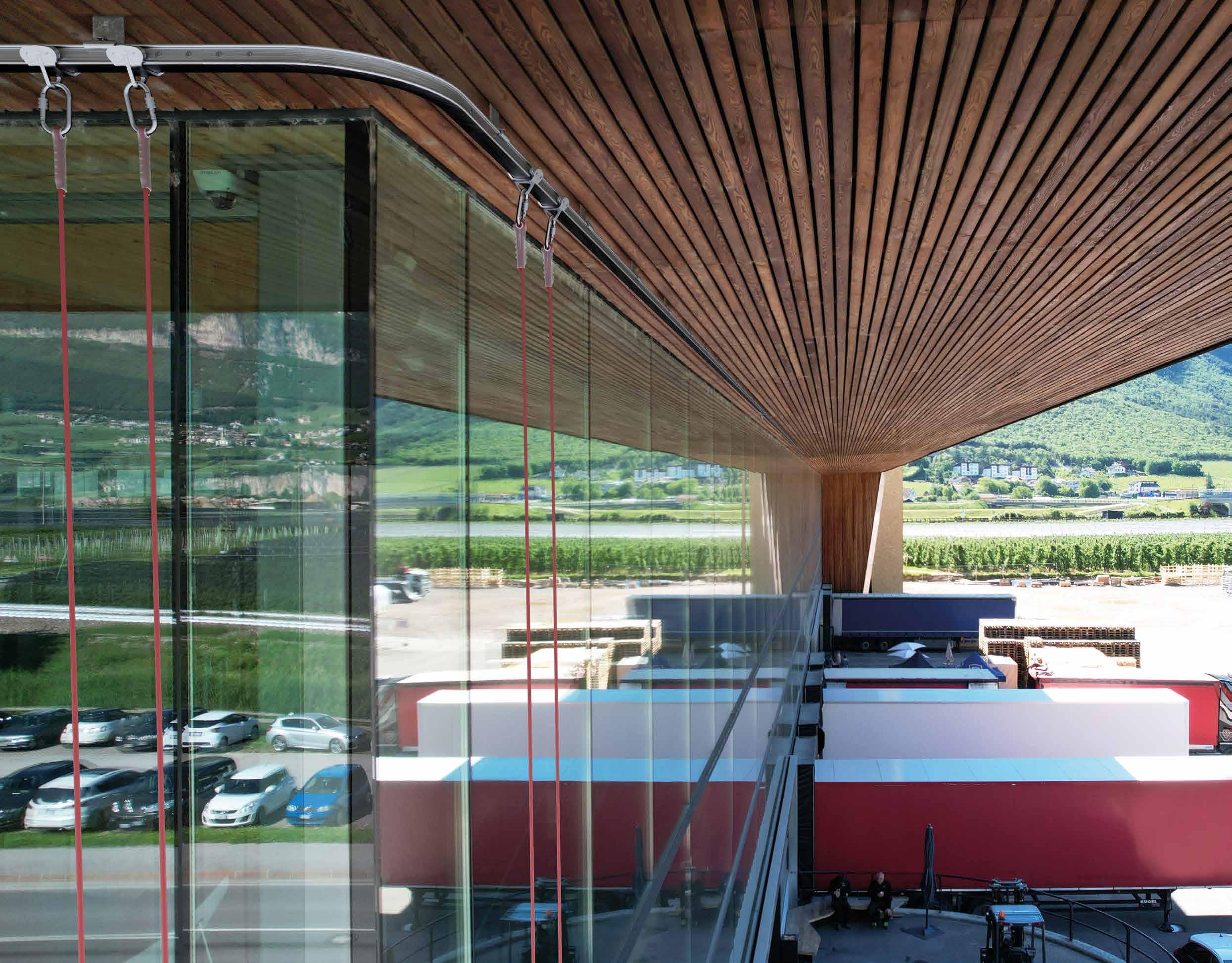
H-RAIL OVERHEAD
HORIZONTAL OVERHEAD RAIL SYSTEM
ADJUSTABLE
Possibility of assembling the rail directly on various substructures with the appropriate plates.
FUNCTIONAL
Rail that allows operators to work with their hands free and in safety by using sliding and retractable devices
SAFE
The system is also suitable and tested for multi-operator suspension use.
Installation of H-RAIL ceiling rail for suspended work for façade cleaning.
H-RAIL COMPONENTS
n. CODE
1 RAILEND / RAILENDOPEN
2 RAILBRAOH
3 TOWER 4 RAILBRAT + RAILBRAT16
5 RAILC150 / RAILC90 / RAILC120 / RAILC135
6 RAILJUN
7 RAIL3000
8 RAILSLIDEOH
TECHNICAL DATA*
substructure minimum thickness direct with RAILBRA
GL24h 100 mm VGS Ø11 HBS12
CLT 200 mm VGS Ø11 HBS12
C20/25 150 mm AB1 SKS10
S235JR 6 mm EKS10 EKS10
TOWER - - -
posizionamento
* The values indicated are the result of experimental tests carried out under the supervision of third parties in accordance with the standard referred to. For a calculation report with minimum distances according to the relevant standard requirements, the substructure must be checked by a qualified engineer before installation.
RAILSLIDEOH
Sliding device for overhead application for fall protection and suspension work. Equipped with four wheels that guarantee excellent sliding even under vertical load.
RAILBRAOH
Support for overhead application. It allows a two-step installation by first installing the bracket on the substructure and then the rail.
H-RAIL
H-RAIL can also be installed without support directly on various substructures. Use the RAILFIXTOOL template to drill the holes.
RAILFIXTOOL
Positioning jig and drilling guide for direct installation on various substructures.
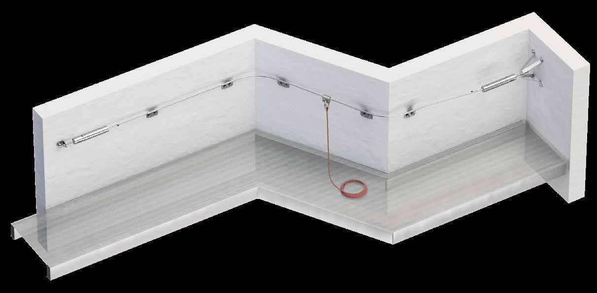
H-RAIL ON WALL
HORIZONTAL WALL-MOUNTED RAIL SYSTEM
AESTHETICS
It can be fixed directly to the structure without the use of special plates.
COMFORT
Operation by means of a sliding device that can be opened at any point of the system.
ASSEMBLY
It can be assembled on different substructures (timber, concrete and steel) to suit all contruction site requirements.
Installation of H-RAILON WALL rail for façade maintenance.
H-RAIL COMPONENTS
n. CODE
1 RAILEND / RAILENDOPEN
2 RAIL3000
TECHNICAL DATA*
3 RAILBRA / RAILBRAT + RAILBRAT12
4 RAILVC90
5 RAILVC135
6 RAILJUN
7 RAILSLIDE / RAILSLIDEOPEN
fastening
substructure minimum thickness direct with RAILBRA
GL24h 100 mm VGS Ø11 HBS12
CLT 200 mm VGS Ø11 HBS12
C20/25 150 mm AB1 SKS10
S235JR 6 mm EKS10 EKS10
work method max supports pacing
posizionamento
fall protection/ restraint
* The values indicated are the result of experimental tests carried out under the supervision of third parties in accordance with the standard referred to. For a calculation report with minimum distances according to the relevant standard requirements, the substructure must be checked by a qualified engineer before installation.
RAILSLIDE
Universal sliding device for rail. Its shape ensures excellent sliding. With locking screw. Anchorage point also suitable for large connectors.
RAILFIXTOOL
Positioning jig and drilling guide for direct installation on various substructures.
RAILBRAT, RAILBRA12
Universal support for maximum versatility and convenience in mounting on different substrates.
H-RAIL | components
MAIN COMPONENTS FOR HORIZONTAL RAIL
coupled support upper element with hole d1= 12 mm to combine with RAILBRA12 or RAILBRA16
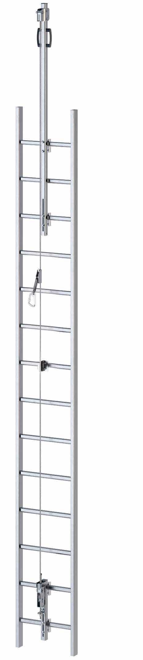
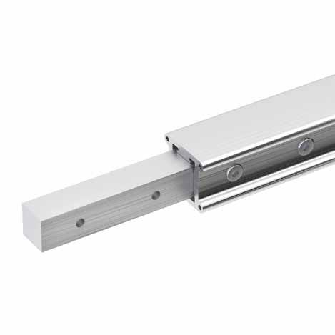
V-RAIL
VERTICAL RAIL SYSTEM
TOTAL CONTROL
Guided type fall arrester with integrated energy absorber, which allows a controlled ascent and descent in safe conditions.
FUNCTIONAL
It can be installed on walls inclined at an angle of up to 15° from the vertical.
PRACTICAL
Possibility of off-centre assembly of the system on a ladder.
Installation of V-RAIL rail on existing ladder for roof maintenance.
V-RAIL COMPONENTS
n. CODE
1
2
3
4
5 VRAILSLIDE
6 VRAILSUPTOP
7 RAILVC90 / RAILVC135
8 VRAILSUPD
n. CODE
1a RAILENDOPEN
2a VRAILBRAW
3a RAIL3000
4a VRAILJUN
5a VRAILSLIDE
6a VRAILSUPTOP
7a RAILVC90 / RAILVC135
8a VRAILSUPD
CODES AND DIMENSIONS
TERMINAL ELEMENT
SLIDING DEVICE
VRAILSLIDE
sliding device with energy absorber for vertical rigid lifeline
VRAILJUN joint element for vertical rail
RAILJUNTOOL template for rail junction holes
RAILFIXTOOL template for holes for direct fastening on the rail
AW 6082 - 1.1191 (C45E) aluminium
VRAILSLIDE
Sliding device with integrated energy absorber allowing vertical movements in comfort and safety.
VRAILBRAL
Support for vertical rail adaptable to any standard ladder. Simple to install.
RAILENDOPEN
Openable end element allowing fast and safe entry into the system using the standard sliding device.
RAIL3000
Available in various RAL colours on request.
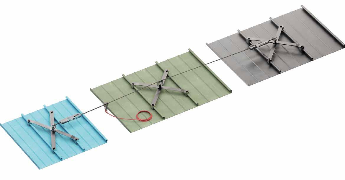
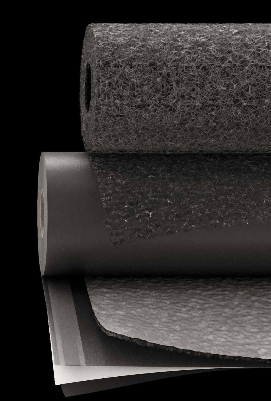
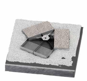
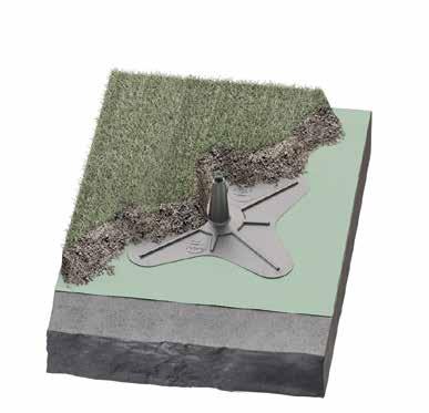
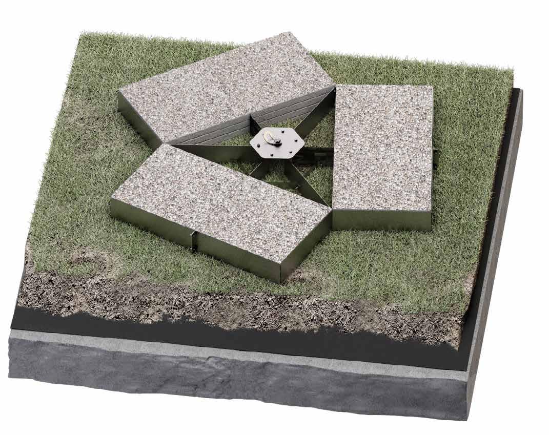
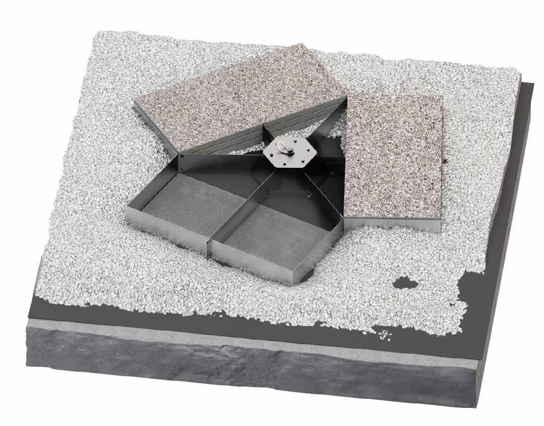
GREEN LINE
LIFE LINE ON SUPPORTS WITH BALLAST
FUNCTIONAL
Supporting system that does not require roof perforation. It avoids thermal bridges and respects the waterproofing of the structure.
FAST INSTALLATION
The system consists of few components which facilitate and speed up mounting.
UNOBTRUSIVE
System with reduced visual impact, almost invisible once installed.
Life line on supports installed at "dead weight" on a flat roof.
TECHNICAL DATA
minimum spacing X min [m] 1,5
maximum spacing X max [m] 8
maximum deflection Ymax [m] 2,38
system characteristics
ballast support dimensions [cm] 300 × 300 (±5%) x 30 (±1%)
support for ballast
n. CODE 1 DD03
DD10 3 DD11 4 DD09
5 DD06 + D005
6 DD07
glass-fibre reinforced plastic cone with laminated ballast mat (frost-resistant)
distance between supports [m] 1,5 - 8
minimum weight of material for ballast* [kg/m2] 80
steel rope type [mm] Ø8 (7 × 19)
durability weatherproof (UV-resistant, it can be used in frost and heat)
* If an additional mat is used: 30 kg/m2 . All technical data are average values. They are based on measurements from various test institutes and measurement laboratories. We reserve the right to make technical changes
NUMBER OF USERS
Unlimited. Each operator working on one span must have at least both spans beside it free of operators. See diagram aside. GREEN LINE tensioner
GREEN LINE | components
CODES AND DIMENSIONS
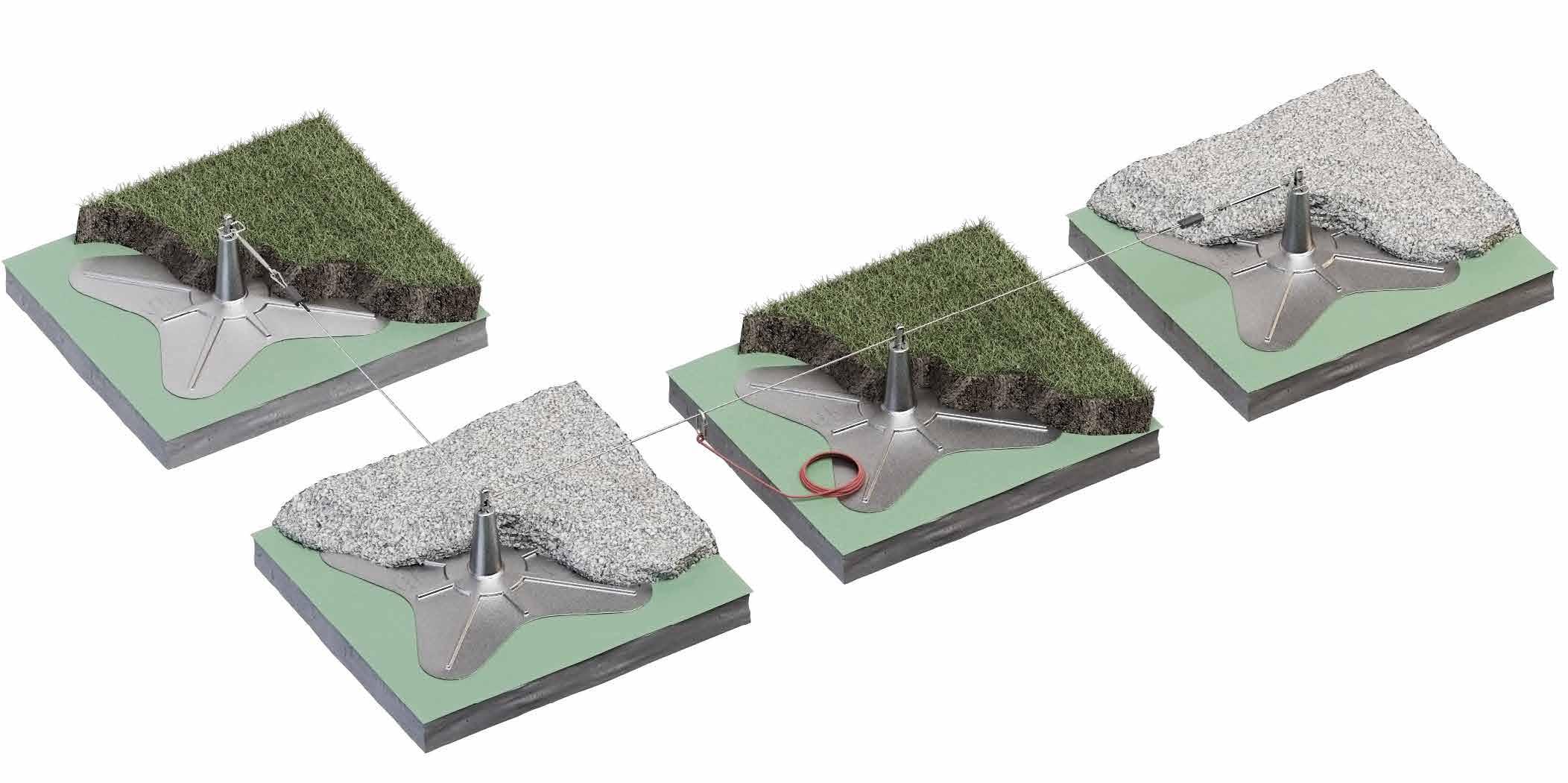
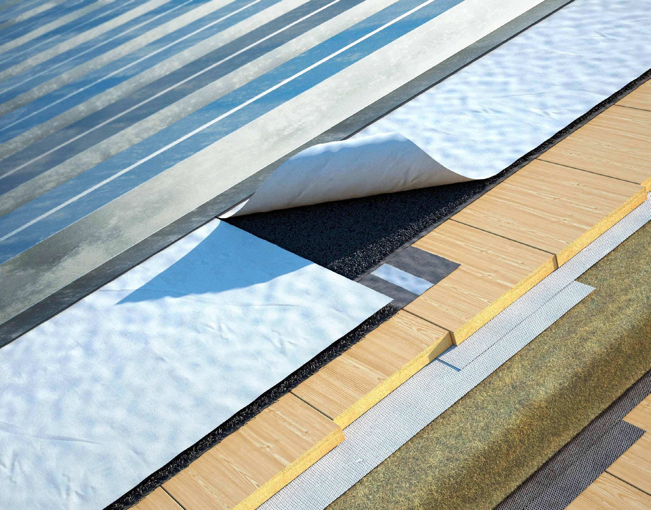
NOISE PROTECTION FOR METAL SHEET ROOFS
TRASPIR METAL is a highly breathable membrane paired with a 3D mat and a protective felt. The top felt prevents impurities from getting into the mat and improves resistance to treading, preventing water stagnation. It is a soundproofing solution, the only one of its kind to have been tested on site for acoustic insulation against the sound of driving rain on the roof.
SO THE NOISE STAYS OUT, AND YOU CAN SLEEP SOUNDLY.
Find out how TRASPIR METAL protects you from noise
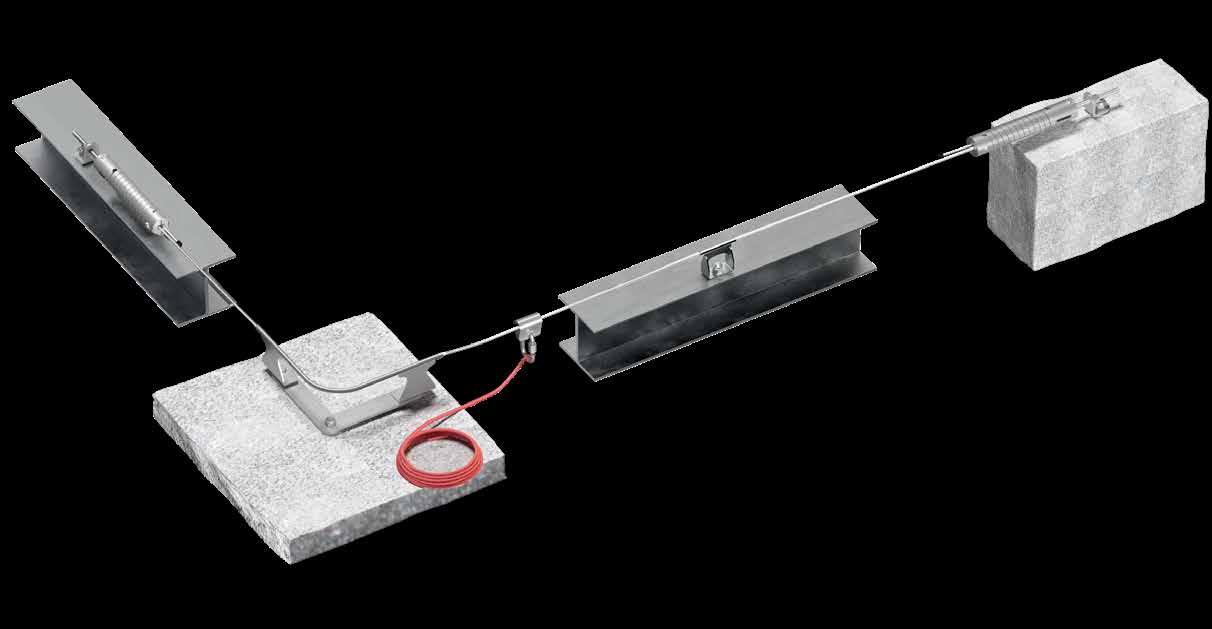
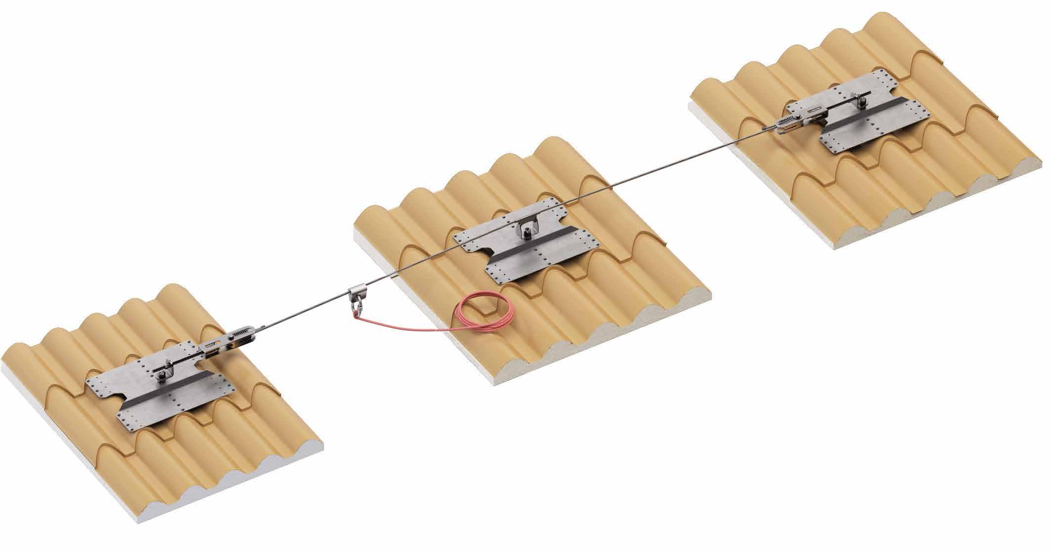
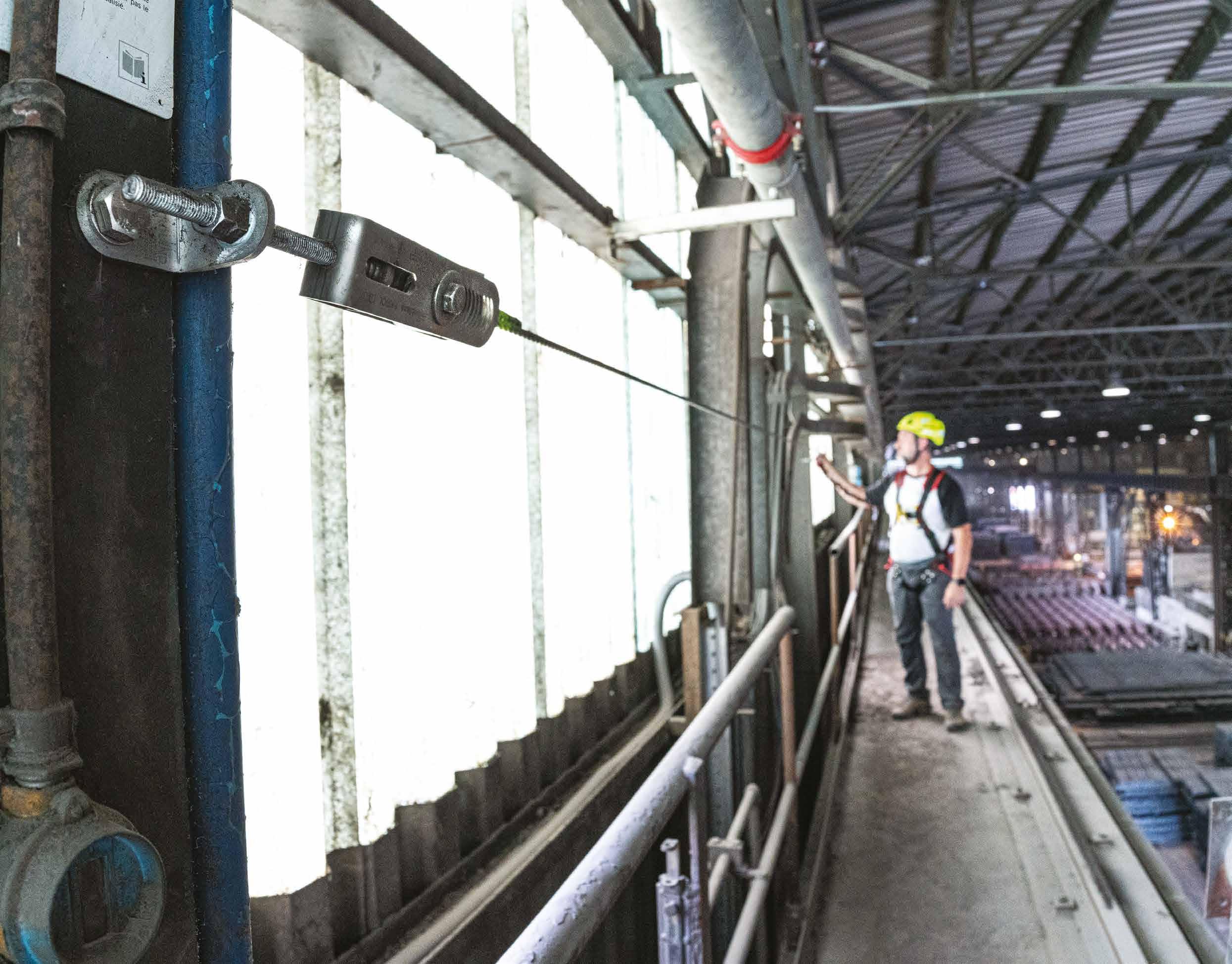
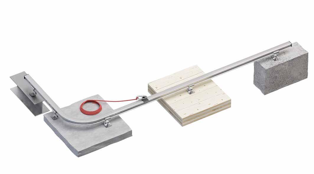
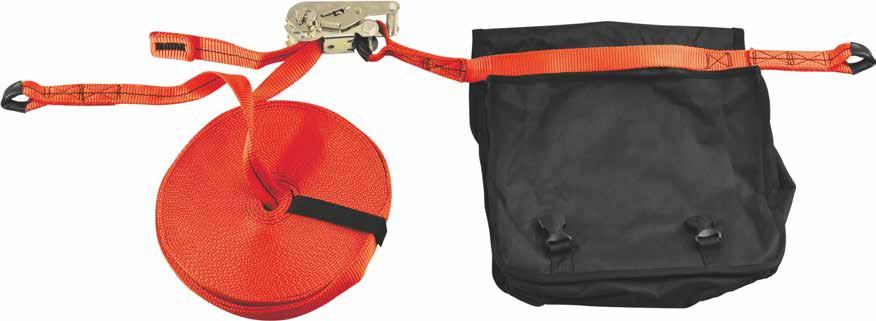
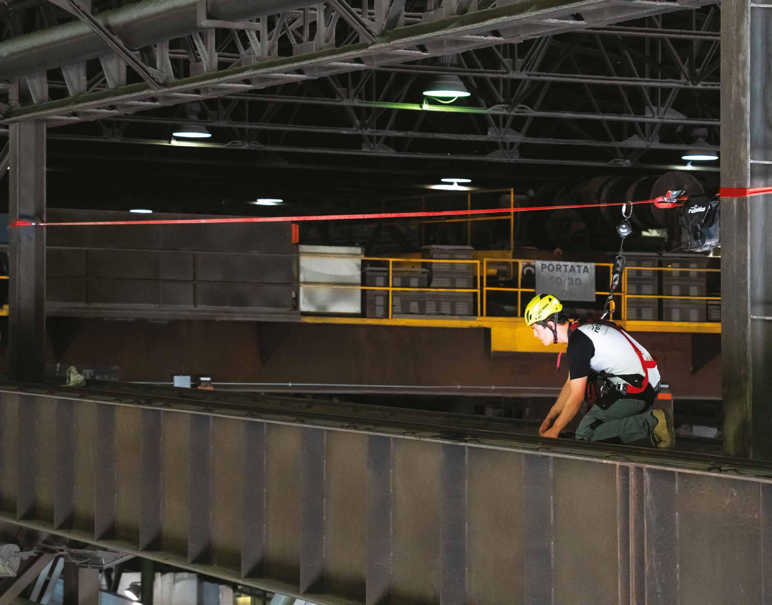
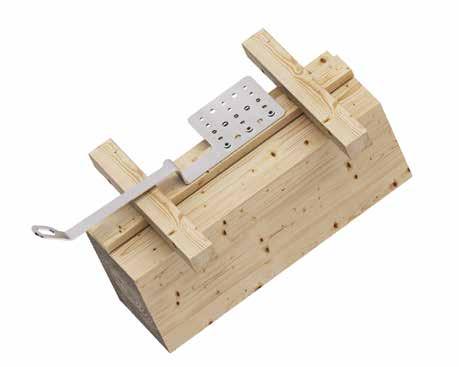
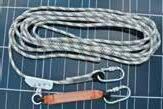
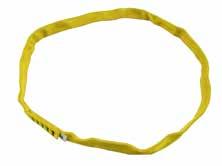
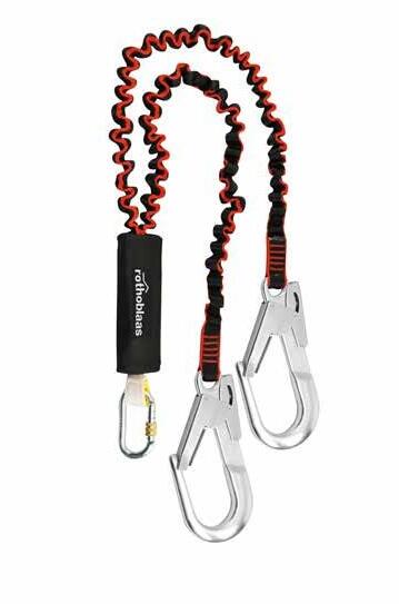
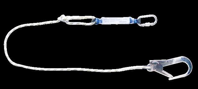
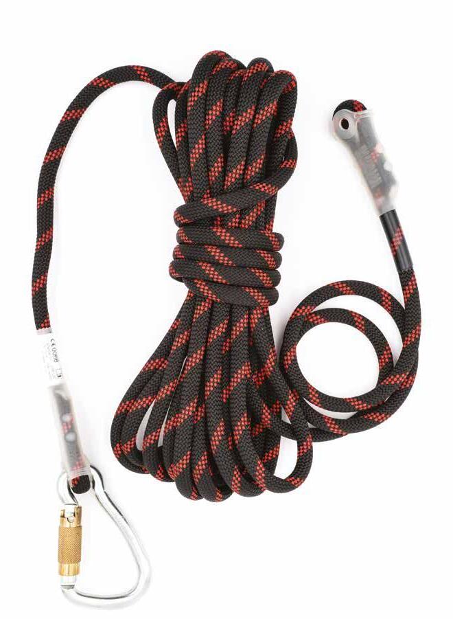
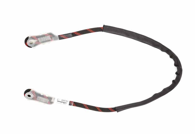
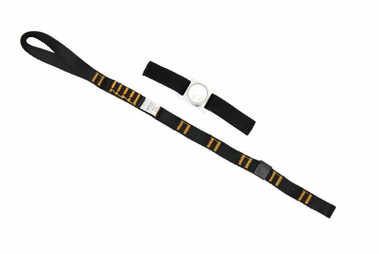
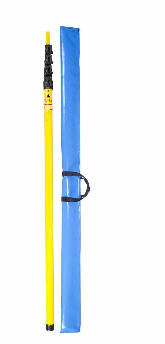
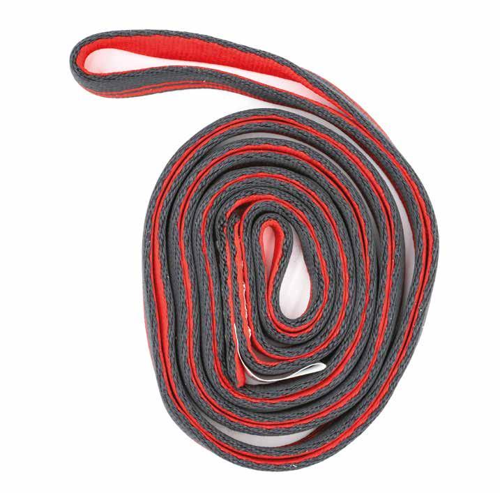
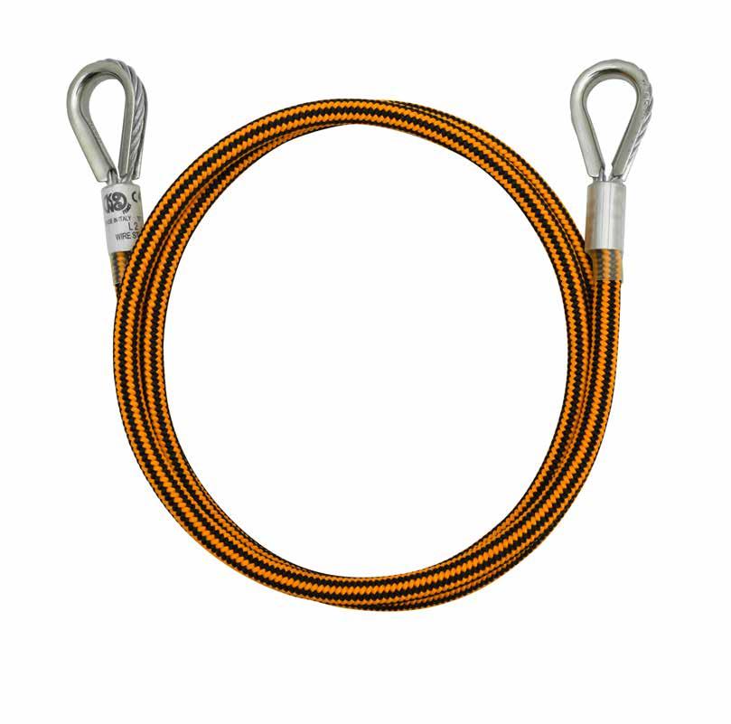
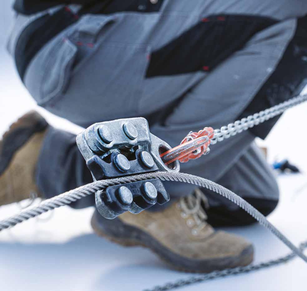
TEMPORARY
TEMPORARY LIFE LINE
• Horizontal temporary life line that is easy to install, with 30 mm polyester band with high load bearing capacity and excellent visibility.
• Number of users: 2 (1 each span)
COMPLEMENTARY PRODUCTS
Temporary lifeline installed on fixed and temporary anchor points.
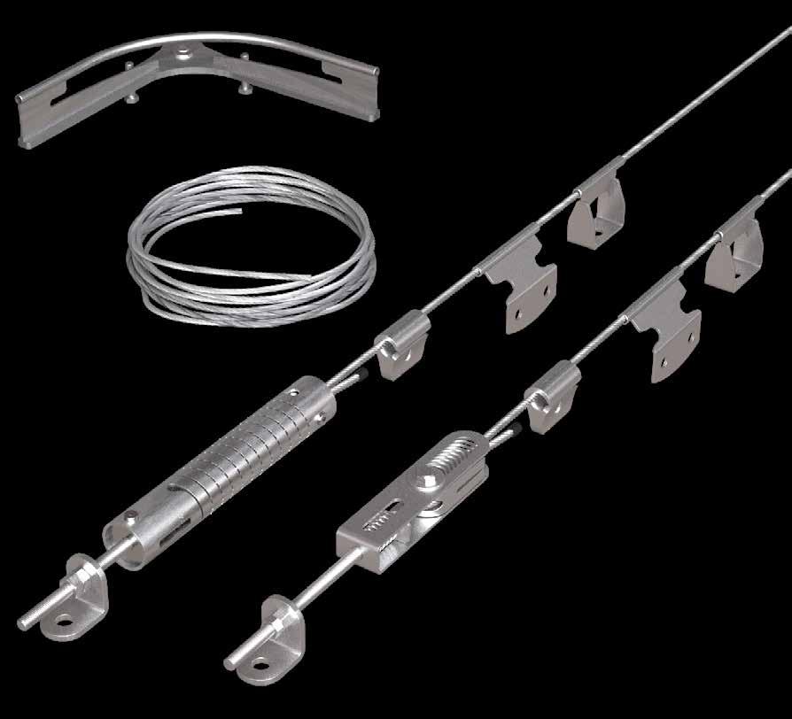
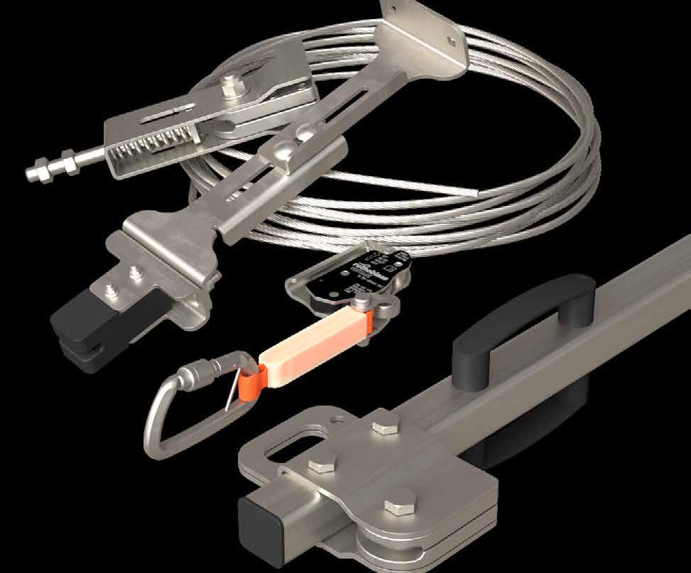
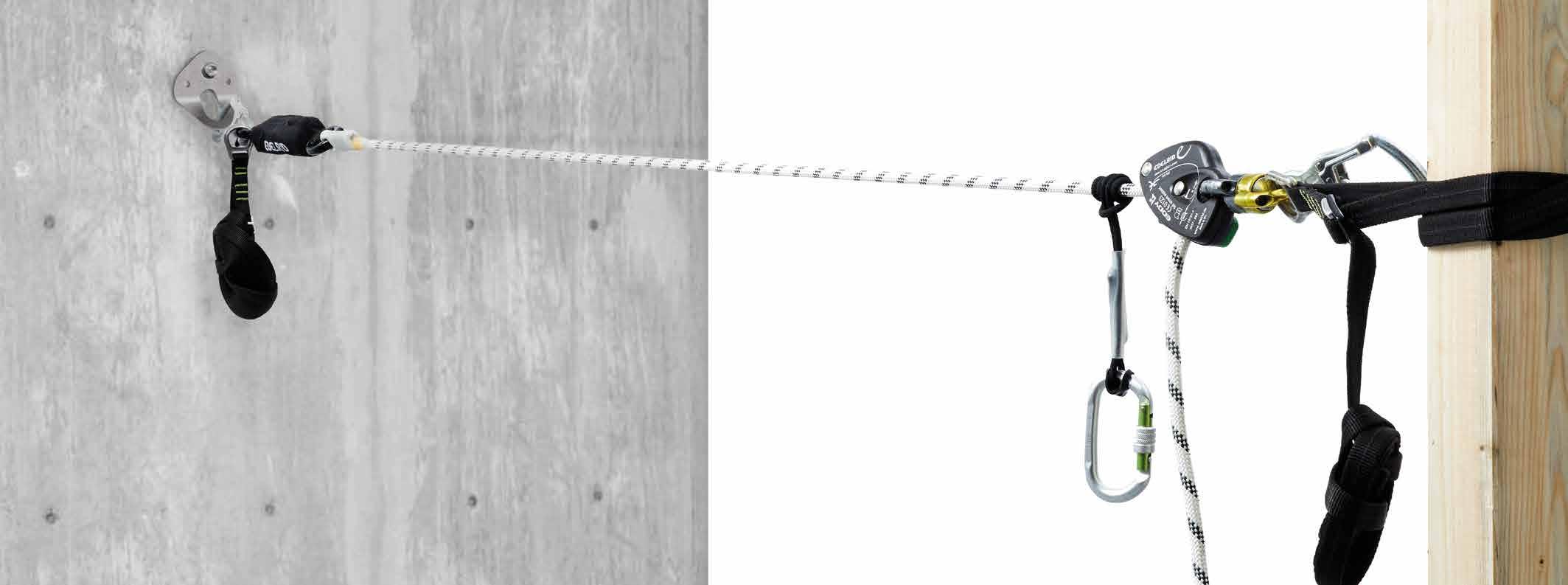
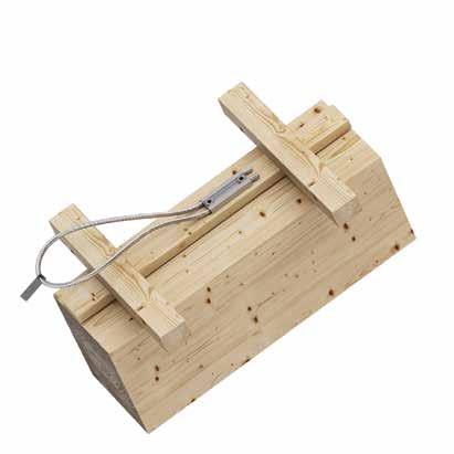
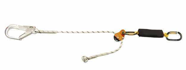
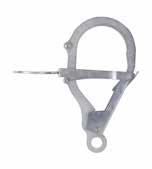
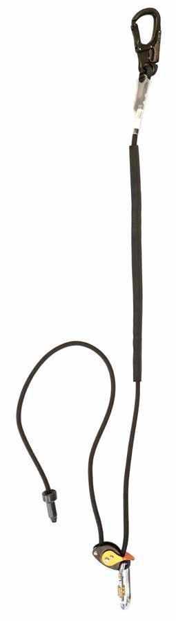
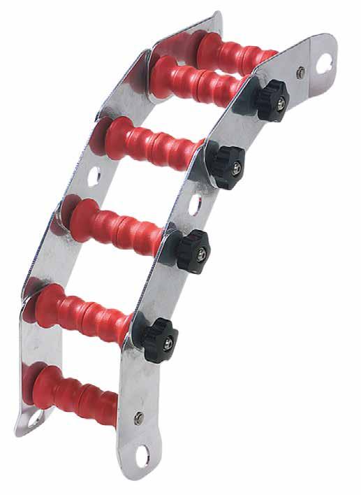
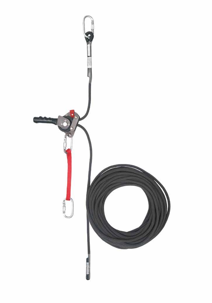
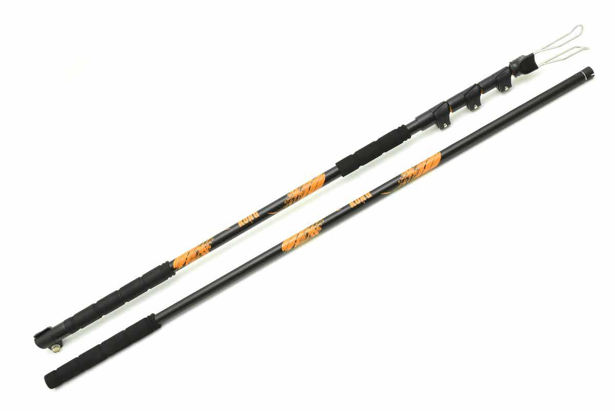
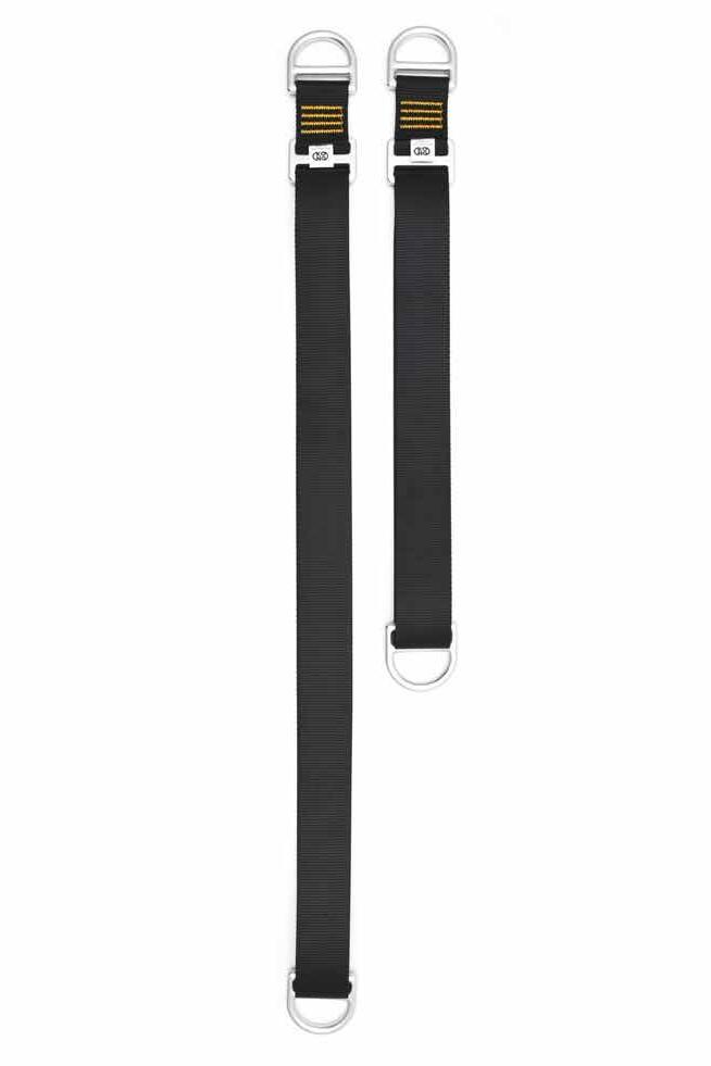
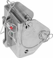
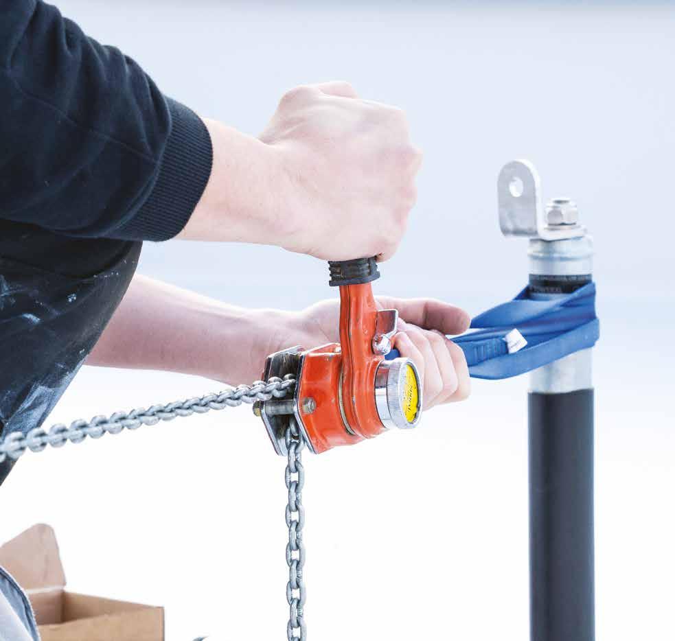
HOLD-SYSTEM®
TEMPORARY HORIZONTAL ANCHORING DEVICE
• Complete system of carabiners and webbing for fastening
• Quick and easy tensioning of the system by one operator using Prusik knot system and self-locking device
• The structure or anchorage points to which the system will be installed must withstand a recommended stress of 9 kN
• Number of users: 2
• Maximum span: 12 m
• Rmin (anchor points) ≤ 6 - 9 kN
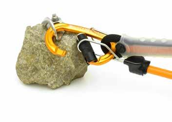
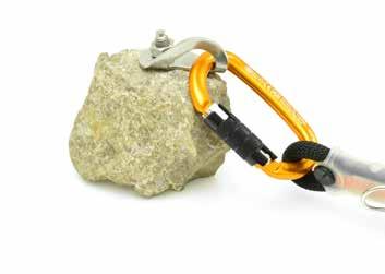
n. description
1 assembly with carabiner or webbing
2 product label
3 self-locking device with emergency release
4 Prusik locking knot for tensioning
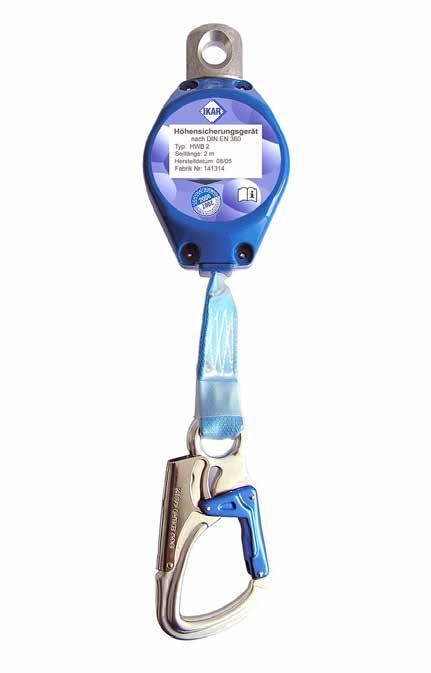
5 lifeline for connection with retractable fall arrest device or lanyards with energy absorber
CODES AND DIMENSIONS
COMPLEMENTARY PRODUCTS
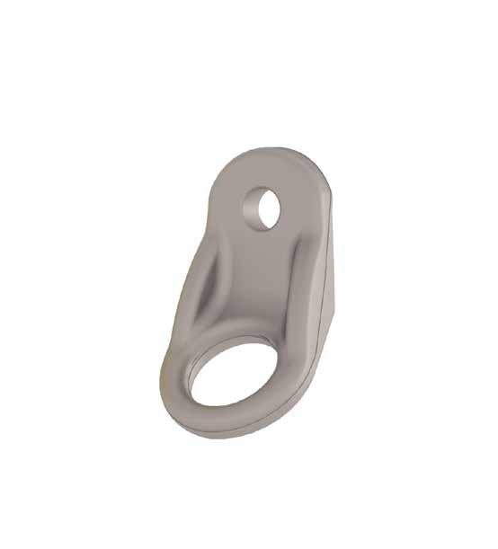
ANCHOR POINTS
ANCHOR POINTS
ANCHOR POINTS
WING
ANCHOR
AOS01 + TOWER/TOWER A2
ANCHOR POINT FOR TIMBER, CONCRETE AND STEEL ROOFS
AOS01 + TOWER XL ANCHOR POINT WITH INCREASED BOTTOM PLATE FOR TIMBER, STEEL AND CONCRETE ROOFS
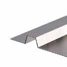
AOS01 + SHIELD ANCHOR POINT FOR TRAPEZOIDAL METAL ROOFS
AOS01 + SHIELD 2 ANCHOR POINT FOR TRAPEZOIDAL METAL ROOFS
AOS01 + SIANK 4
ANCHOR POINT FOR STANDING SEAM METAL ROOFS
AOS01 + SEAMO ANCHOR POINT FOR ROUND SEAM
AOS01 + COPPO ANCHOR POINT FOR ROOFS WITH FAUX TILES
AOS01 + BLOCK ANCHOR POINT WITH BALLAST FOR FLAT ROOFS
GLUE ANCHOR GLUED ANCHOR POINT FOR BITUMEN AND PVC ROOFS
WING 2
ANCHOR POINT FOR SUSPENDED
THE RIGHT ANCHOR POINT FOR EACH STRUCTURE
HOOK EVO 2.0
AOS01 +
WING AOS
MOBILE ROD
HOOK EVO 2.0
AOS01 + TOWER XL
+ TOWER XL AOS01 + TOWER/A2 AOS
AOS01 + SEAMO AOS01 + SHIELD 2 AOS01 + SHIELD
+ TOWER XL SIANK
AOS01 + COPPO AOS01 + SIANK 4
GLUE ANCHOR GLUE ANCHOR
AOS01 + BLOCK
AOS01 + BLOCK GREEN POINT
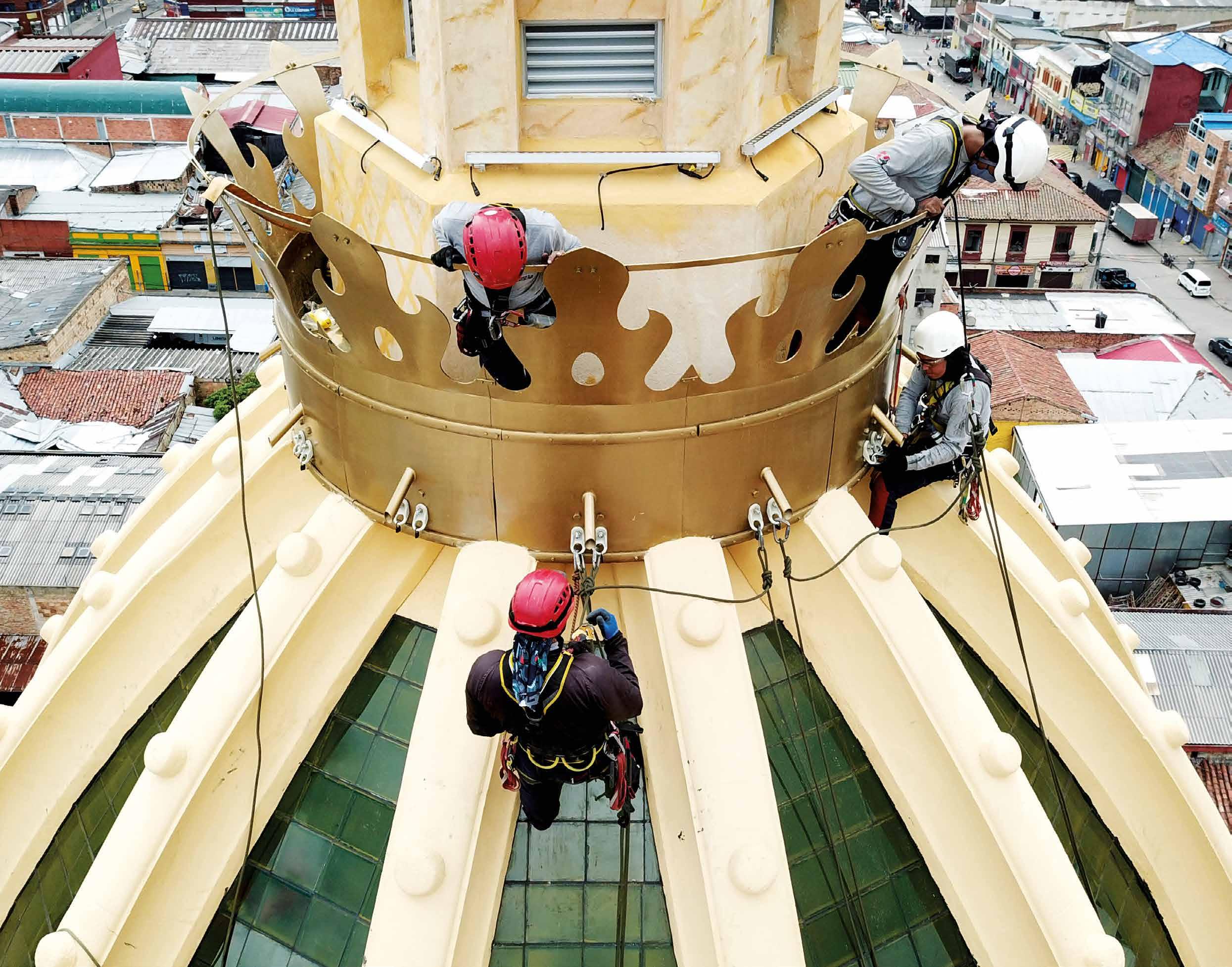
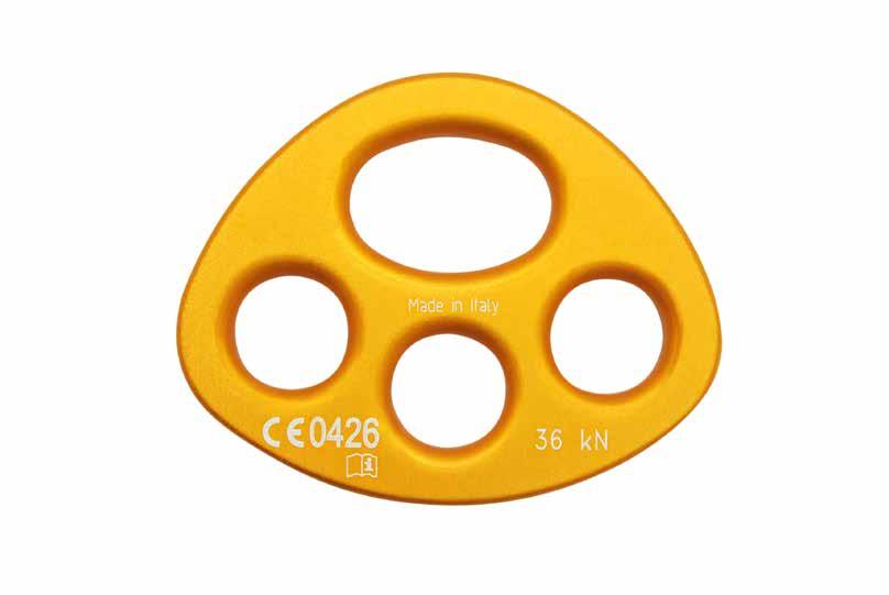
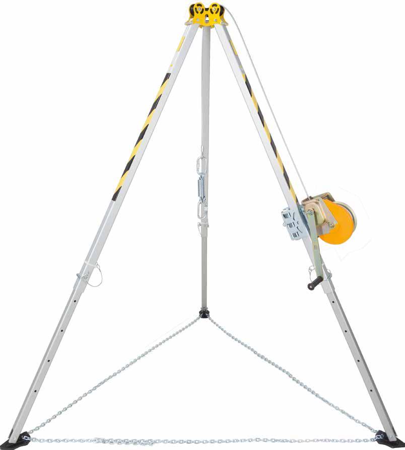
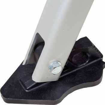
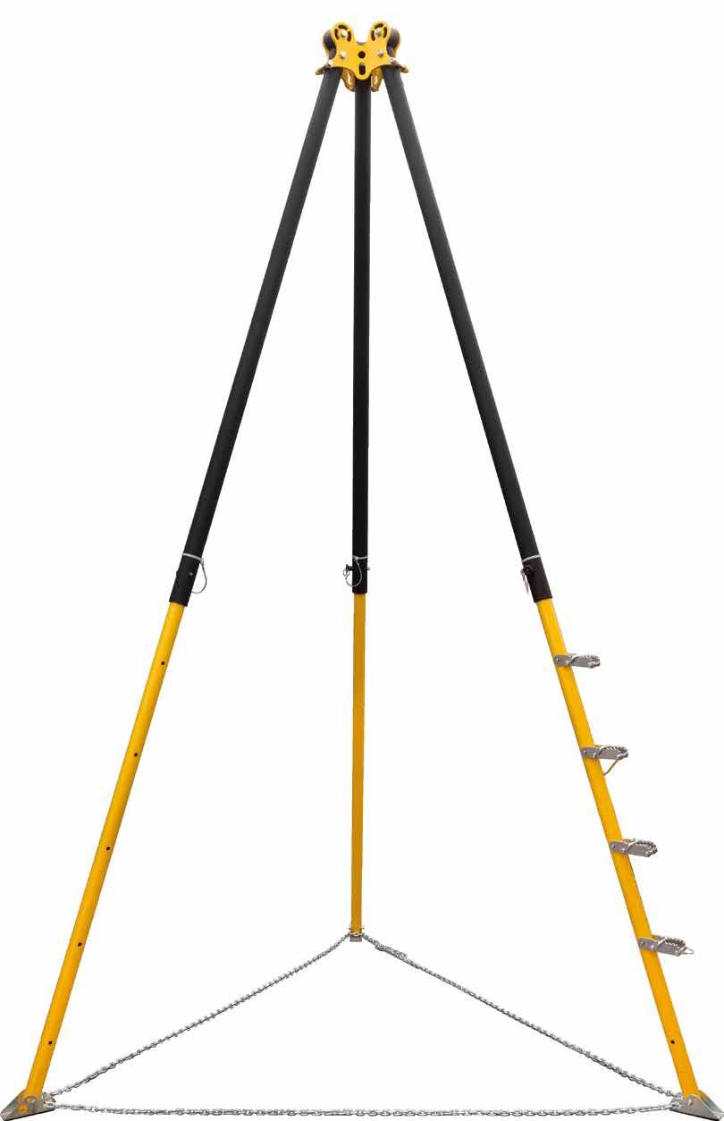
ANCHOR POINT FOR WORK AT HEIGHT AND IN SUSPENSION
SOLID
Extremely robust and reliable.
VERSATILE
Can be used both for suspended work (1 person) and for protection against falls from height (3 people).
MULTIPURPOSE
With three different versions of two materials and in three different colours, you will always find the right product for every application and environmental condition.
Single WING anchorage points installed for use in suspension for the maintenance of a church dome.
TECHNICAL DATA*
substructure minimum thickness fasteners
VGS Ø11VGS AB7
GL24h 100 x 160 mm
XEPOX F XEPOX F
AB1 A4 M16 rod + MUT + ULS barra M16 + MUT + ULS
CLT 100 mm 8.8 Ø16 rod + MUT + ULS barra M16 + MUT + ULS
* The values indicated are the result of experimental tests carried out under the supervision of third parties in accordance with the standard referred to. For a calculation report with minimum distances according to the relevant standard requirements, the substructure must be checked by a qualified engineer before installation.
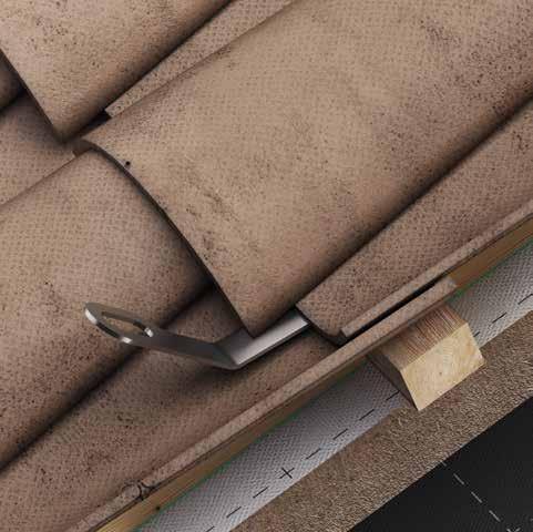
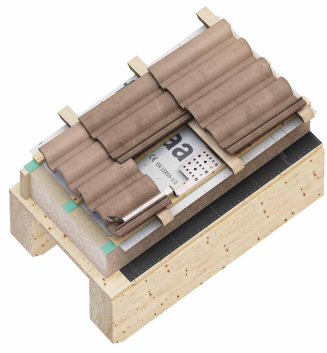
Under-tile fastening ensures a low visual impact in the roofing, for an aesthetically satisfactory result.
ADJUSTABLE
Quick and easy installation using Ø8 HBS screws. The base plate with an increased number of holes allows the anchor to be mounted in different positions, depending on the type of roof tiles.
TECHNICAL DATA*
substructure minimum thickness fasteners
* The values indicated are the result of experimental tests carried out under the supervision of third parties in accordance with the standard referred to. For a calculation report with minimum distances according to the relevant standard requirements, the substructure must be checked by a qualified engineer before installation.
CODES AND DIMENSIONS
HOOKEVO
ANCHOR POINT
UNOBTRUSIVE
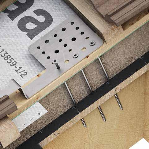
Under-tile fastening ensures a low visual impact in the roofing, for an aesthetically satisfactory result.
PRACTICAL
Fast, simple installation. The bottom plate allows the anchor to be assembled in different positions on both timber and concrete, depending on the height of the battens and the type of tiles.
TECHNICAL DATA*
* The values indicated are the result of experimental tests carried out under the supervision of third parties in accordance with the standard referred to. For a calculation report with minimum distances according to the relevant standard requirements, the substructure must be checked by a qualified engineer before installation.
CODES AND DIMENSIONS
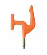
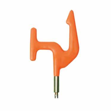
HOOK SPIKE
ANCHOR POINT WITH LADDER HOOK
PRACTICAL
Shape designed to be able to attach a portable ladder to facilitate the operator's ascent on steep roofs.
SAFE
Tested according to the standard directly on the substructure, it guarantees safety and freedom of movement in all directions.
VERSATILE
Thanks to the three different heights of the plate, it is possible to choose and assemble the hook according to the type of tile installed on the roof.
Installation of anchor point with HOOK SPIKE ladder hook on timber roofing.
TECHNICAL DATA*
* The values indicated are the result of experimental tests carried out under the supervision of third parties in accordance with the standard referred to. For a calculation report with minimum distances according to the relevant standard requirements, the substructure must be checked by a qualified engineer before installation.
CODES AND DIMENSIONS
ANCHOR POINT
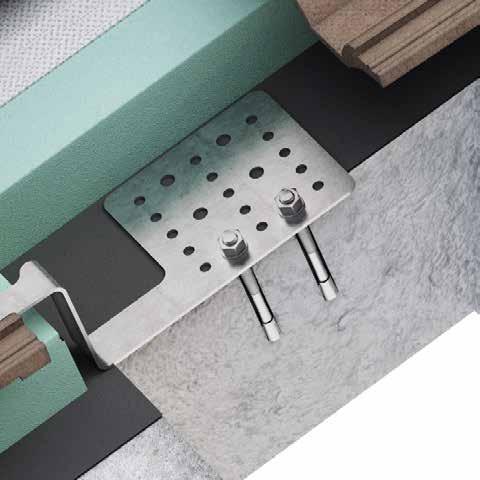
UNOBTRUSIVE
Under-tile fastening ensures a low visual impact, ideal for installation on roofs in historic centres.
FAST
Fast and easy installation, with just two HBS Ø8 screws.
TECHNICAL DATA*
* The values indicated are the result of experimental tests carried out under the supervision of third parties in accordance with the standard referred to. For a calculation report with minimum distances according to the relevant standard requirements, the substructure must be checked by a qualified engineer before installation.
CODES AND DIMENSIONS
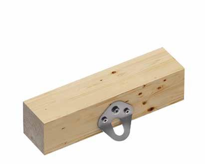
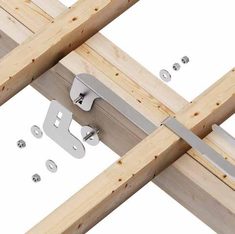
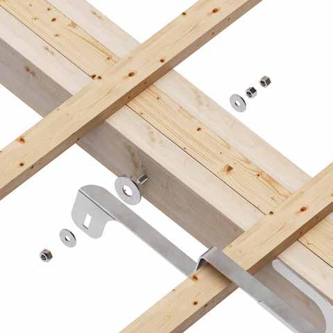
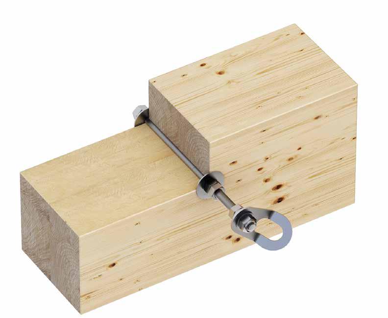
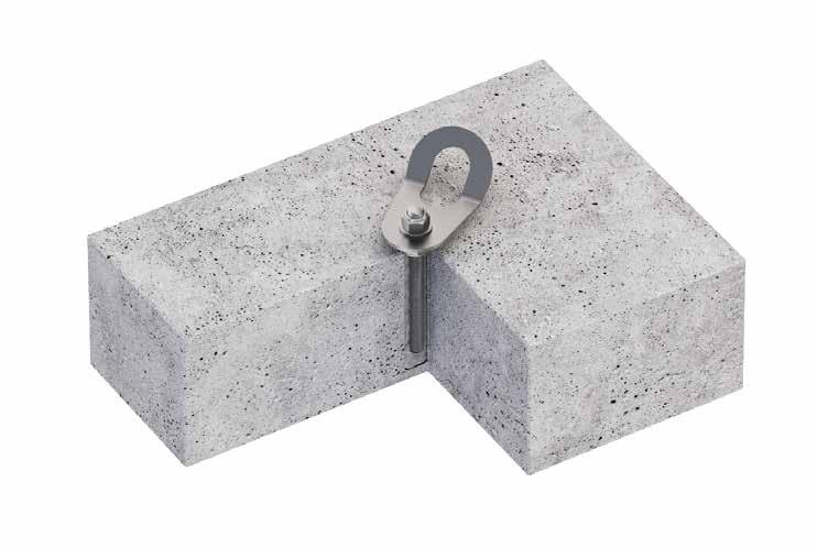
ANCHOR POINT FOR SMALL STRUCTURES
ADJUSTABLE
Can be installed on small beams, with minimum dimensions of 38 x 68 mm with no limits on maximum width.
MULTIPURPOSE
Can be used as single points or as a hook for ladders.
TECHNICAL DATA*
* The values indicated are the result of experimental tests carried out under the supervision of third parties in accordance with the standard referred to. For a calculation report with minimum distances according to the relevant standard requirements, the substructure must be checked by a qualified engineer before installation.
CODES AND DIMENSIONS
BEFSLIM2
BEFSLIM1
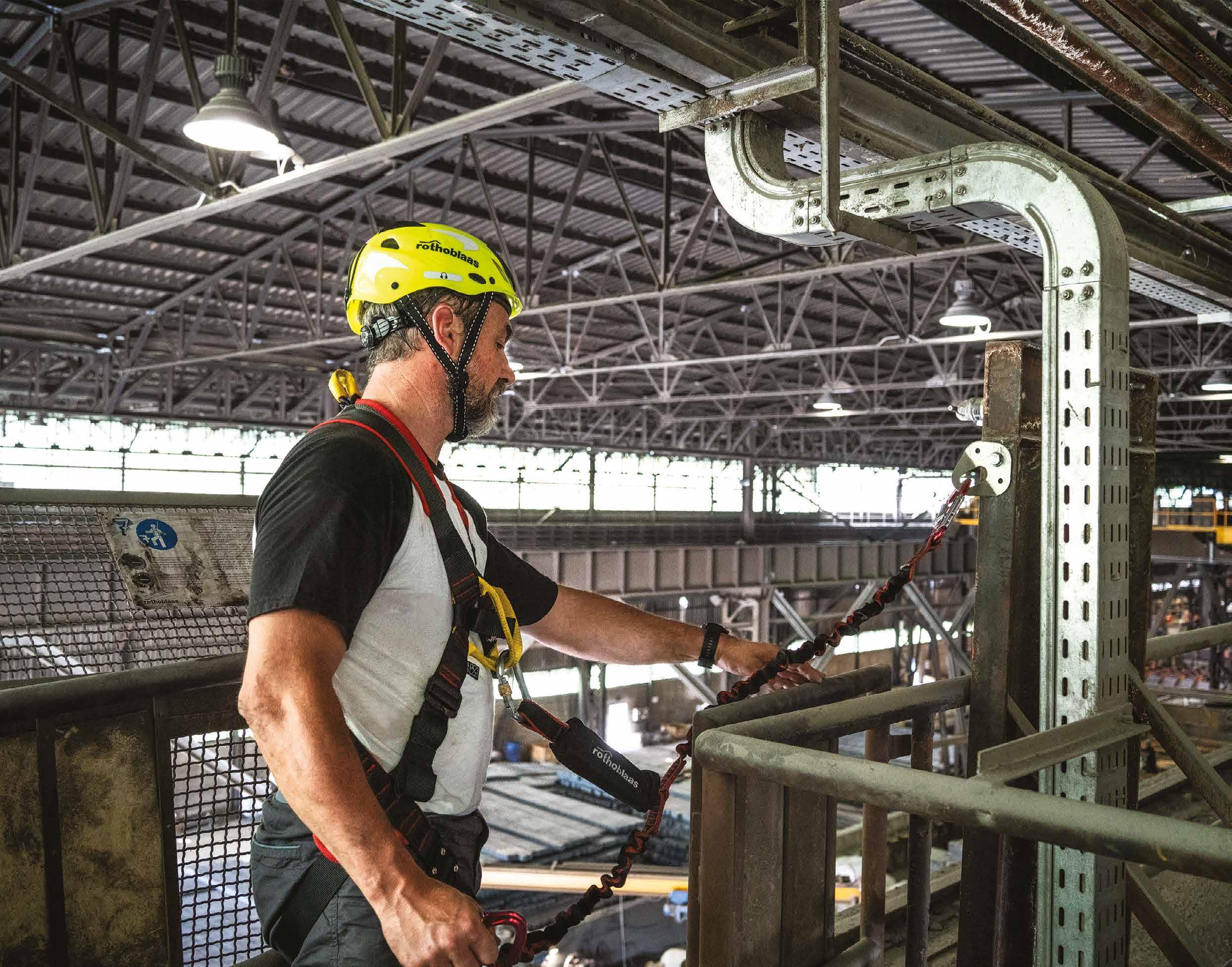
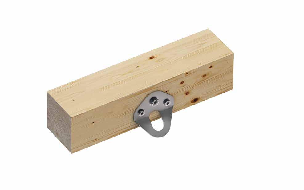
ANCHOR POINT
PRACTICAL
Thanks to its lightweight and compact size, this anchor can be installed quickly and easily.
SAFE
Laser cut from a single piece with no welding points, it improves safety in all its applications.
VERSATILE
Ideal as an anchor point in multiple environments, it allows the operator to safely access.
KITE
TECHNICAL DATA*
substructure minimum thickness fasteners
GL24h 100 x 100 mm 2 x HBS Ø8HBS Ø8 1x VGS Ø11VGS AB7
substructure minimum thickness fasteners C20/25 140 mm AB1 Ø12 VGS AB7 M10 M12 8.8 rod + ULS + MUT barra 8.8 Ø16 + MUT + ULS
HYB-FIX M10 VIN SKR CE
* The values indicated are the result of experimental tests carried out under the supervision of third parties in accordance with the standard referred to. For a calculation report with minimum distances according to the relevant standard requirements, the substructure must be checked by a qualified engineer before installation.
CODES AND DIMENSIONS
ACCESSORIES
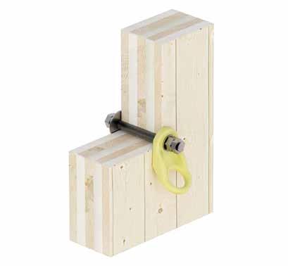
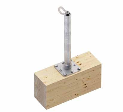
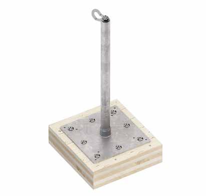
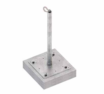
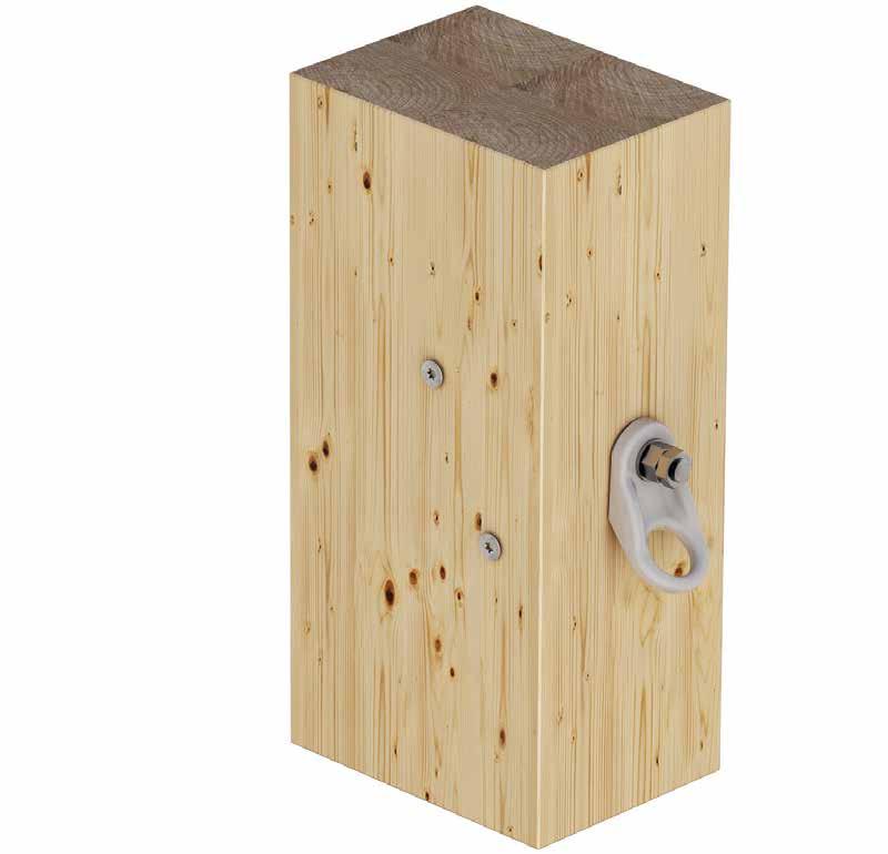
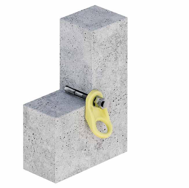
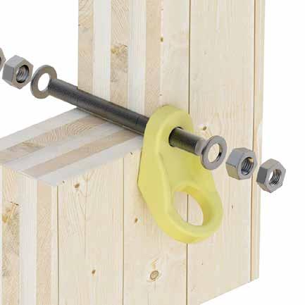
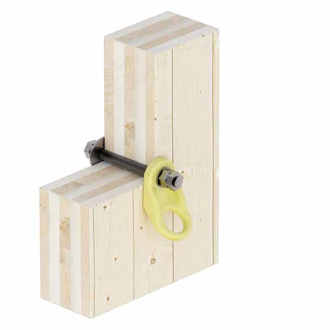
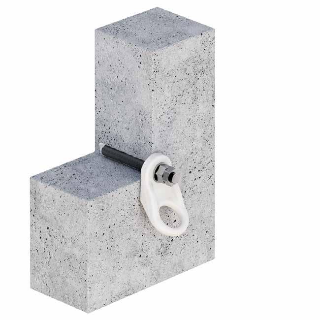
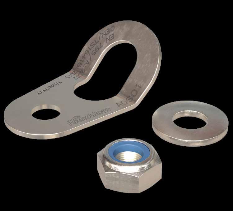
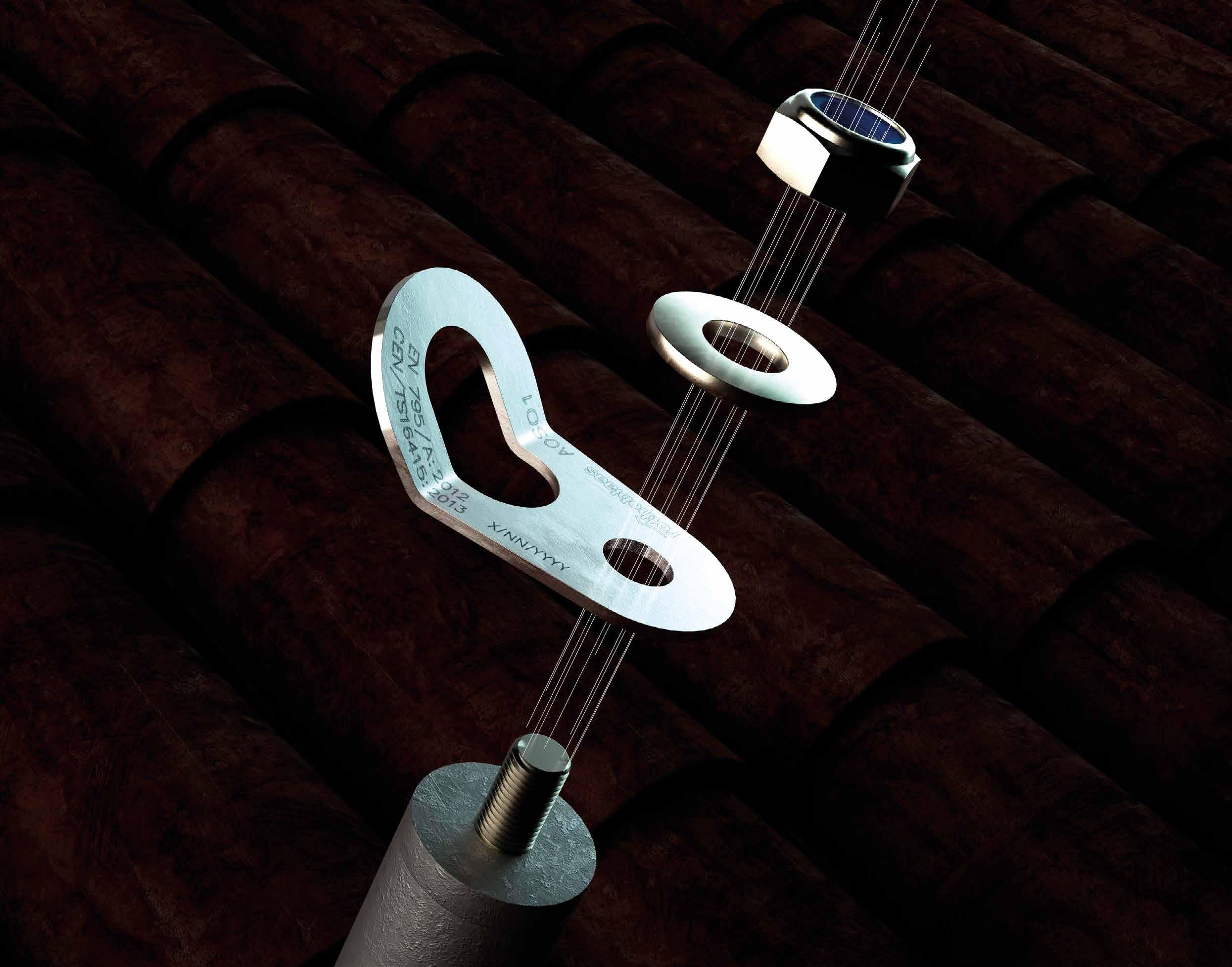
ANCHOR POINT
FUNCTIONAL
The 360° swivel eyelet allows the operator total freedom of movement.
COMPLETE
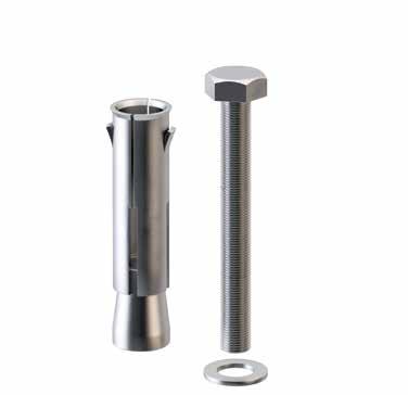
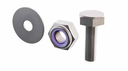
Supplied in a handy kit complete with bolts and washers for installation.
UNIVERSAL
The threaded rod available in various lengths allows the anchor to adapt to any type of timber, concrete and steel structure.
AOS
TECHNICAL DATA*
* The values indicated are the result of experimental tests carried out under the supervision of third parties in accordance with the standard referred to. For a calculation report with minimum distances according to the relevant standard requirements, the substructure must be checked by a qualified engineer before installation.
CODES AND DIMENSIONS
ACCESSORIES
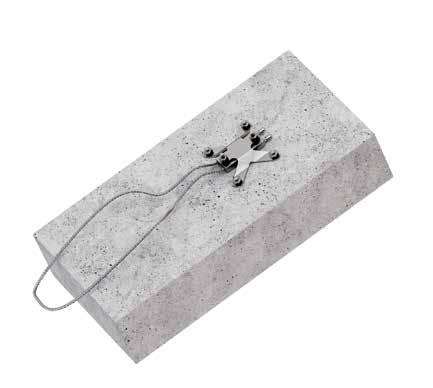
OMEGA
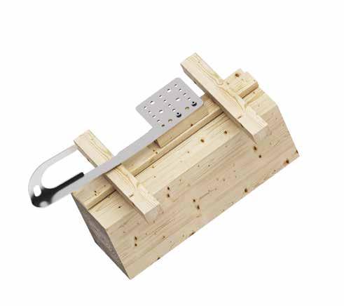
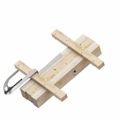
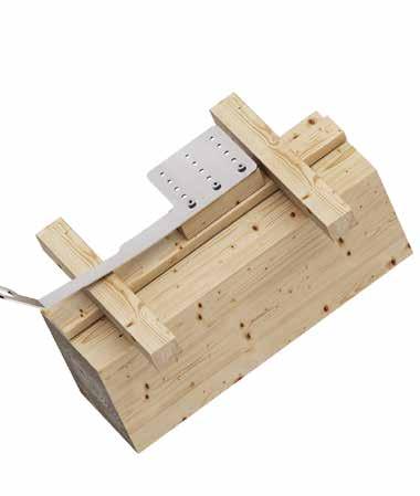
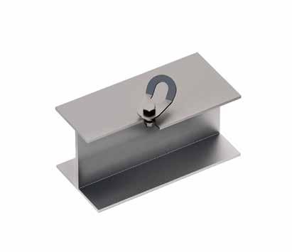
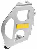
SIANK
ANCHOR
POINT FOR STANDING SEAM METAL ROOFS
EFFICIENT
The system is fixed to a single seam of the sheet using a few tools.
UNOBTRUSIVE
Device fixed to the seam by means of a single clamp, without the need to drill holes in the metal sheet, guaranteeing its impermeability and durability.
TECHNICAL DATA*
* The values indicated are the result of experimental tests carried out under the supervision of third parties in accordance with the standard referred to. For a calculation report with minimum distances according to the relevant standard requirements, the substructure must be checked by a qualified engineer before installation.
CODES AND DIMENSIONS
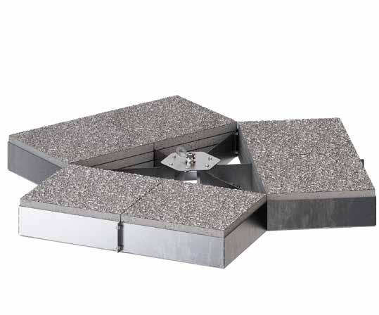
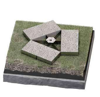
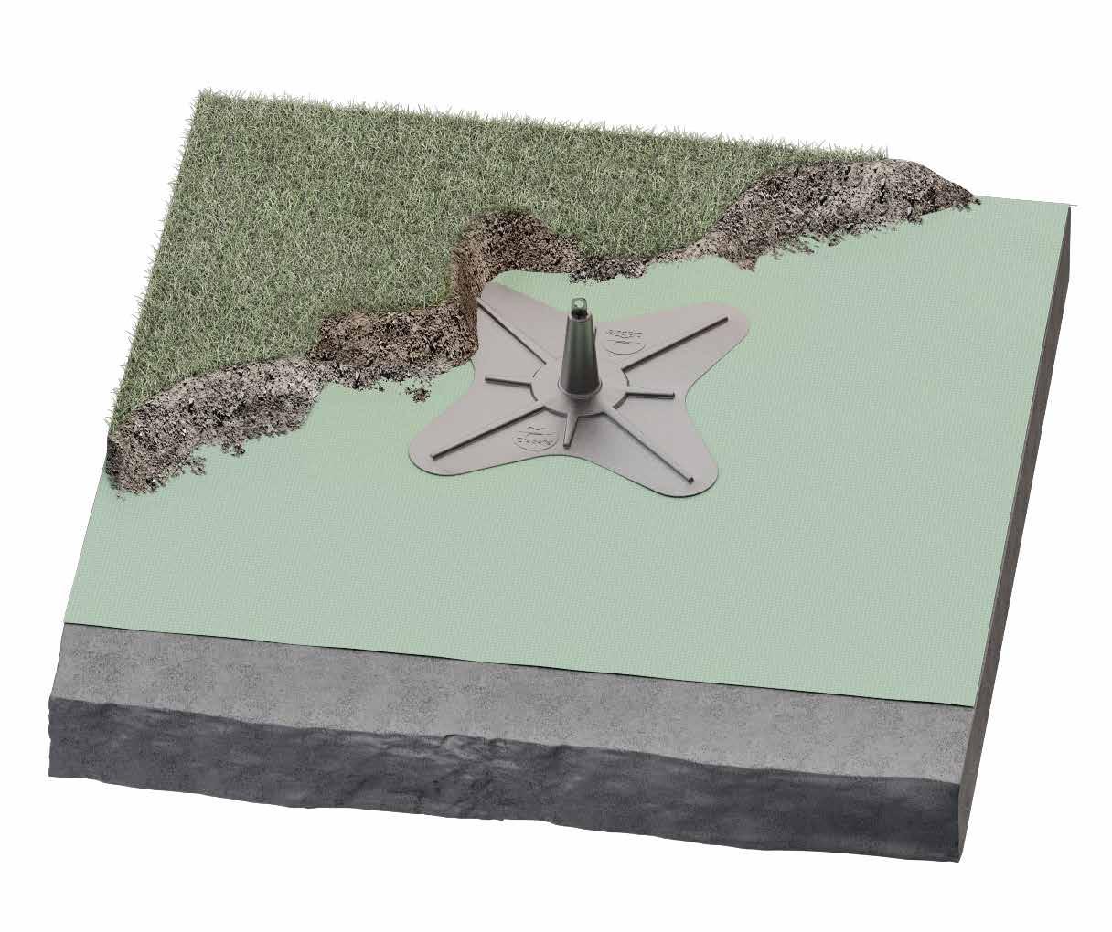
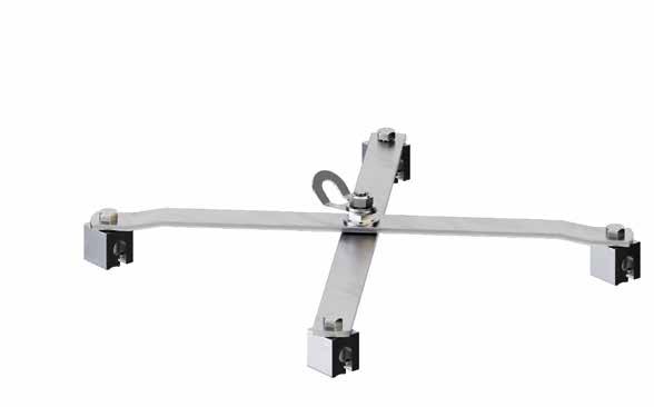
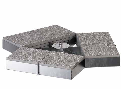
GREEN POINT
ANCHOR POINT WITH BALLASTS
FAST INSTALLATION
The system consists of few components which facilitate and speed up mounting.
FUNCTIONAL
Support system which does not require the roofing to be drilled, thereby preventing thermal bridges and ensuring the structure waterproofing.
TECHNICAL DATA*
of operators dimensions
standard tarpaulin dimensions 3x3 m VLF non-woven geotextile for ballast > 80 kg/m2 for each pole = 720 kg standard tarpaulin dimensions 3x3 m VLF non-woven geotextile for ballast > 200 kg/m2 for each pole = 1800 kg
* They are based on measurements from various test institutes and measurement laboratories. We reserve the right to make technical changes.
CODES AND DIMENSIONS
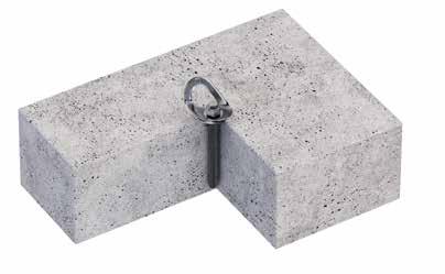
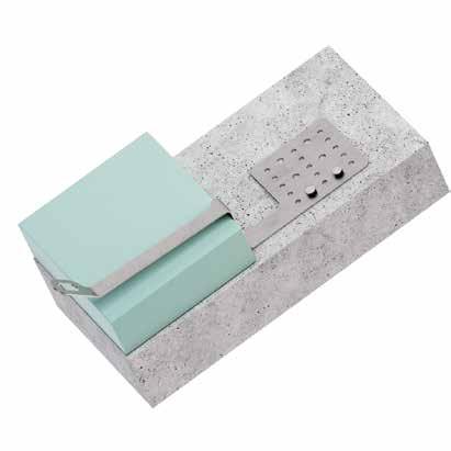
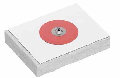
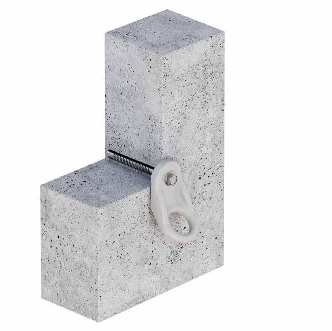
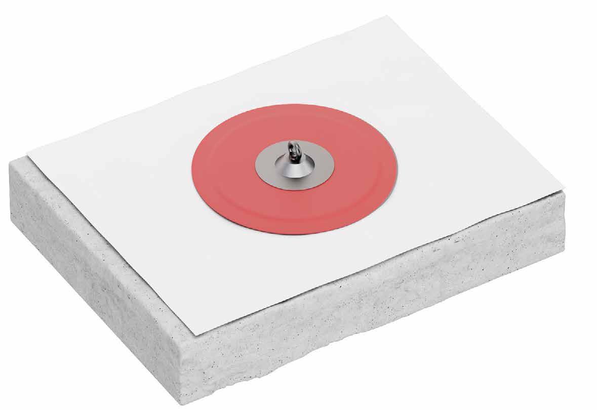
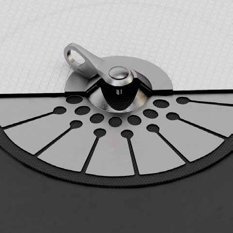
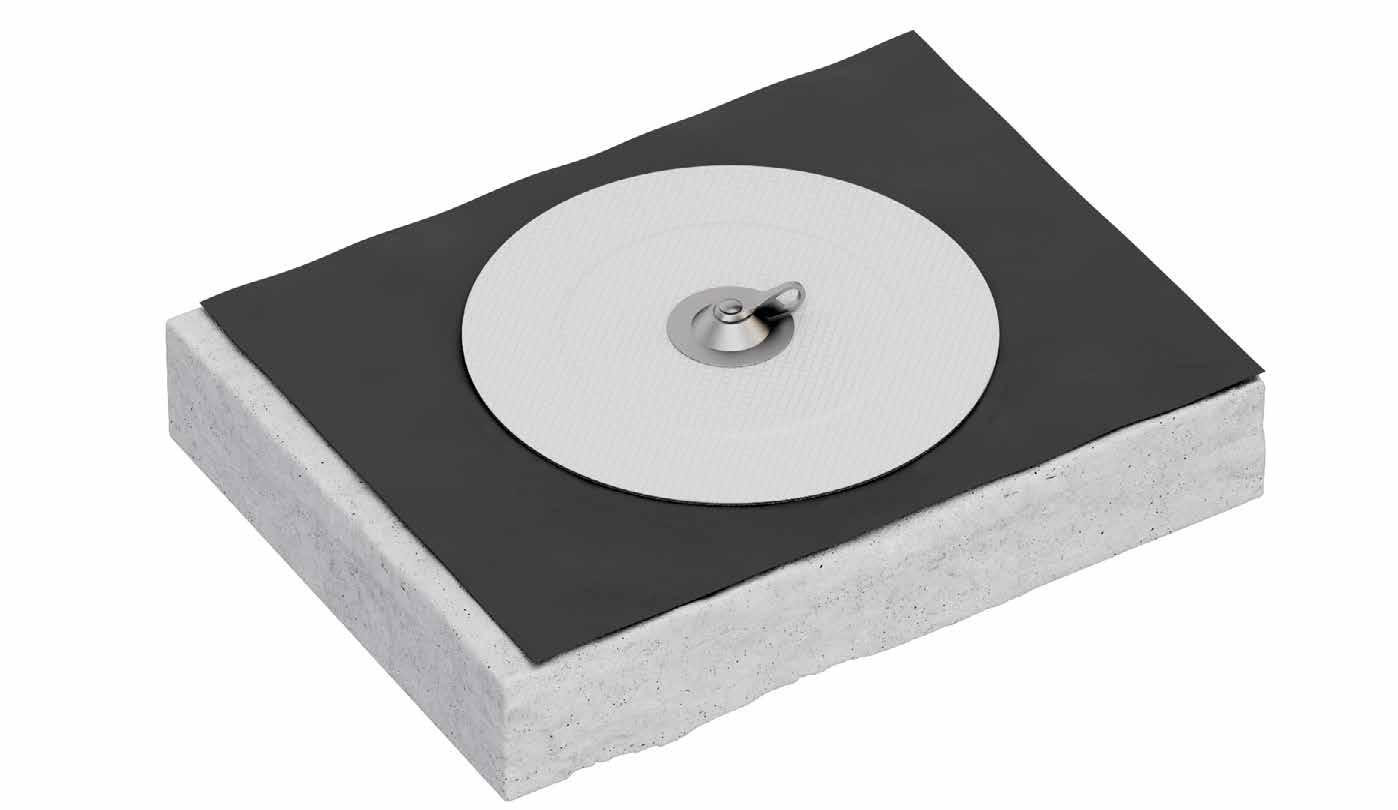
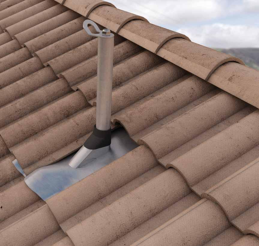
GLUE ANCHOR
GLUED ANCHOR POINT FOR BITUMEN AND PVC ROOFS
FUNCTIONAL
The application does not require any perforation of the PVC or bituminous sheathing, guaranteeing perfect waterproofing of the roof.
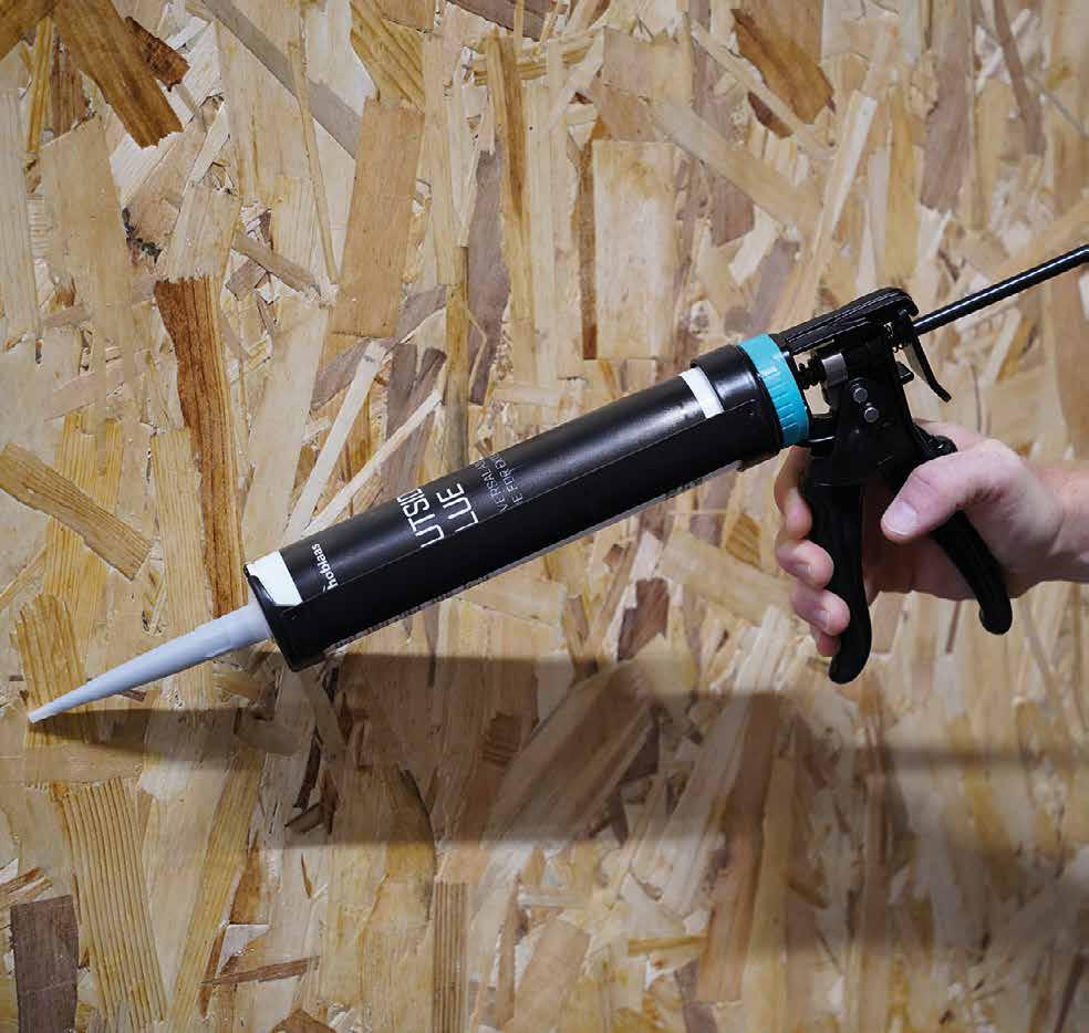
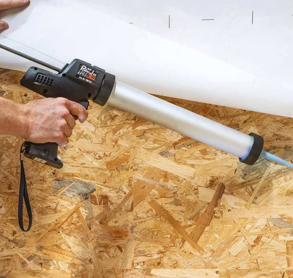
FAST INSTALLATION
The system is quickly installed with very few tools.
VERSATILE
Equipped with a 360° swivel eyelet to facilitate work operations.
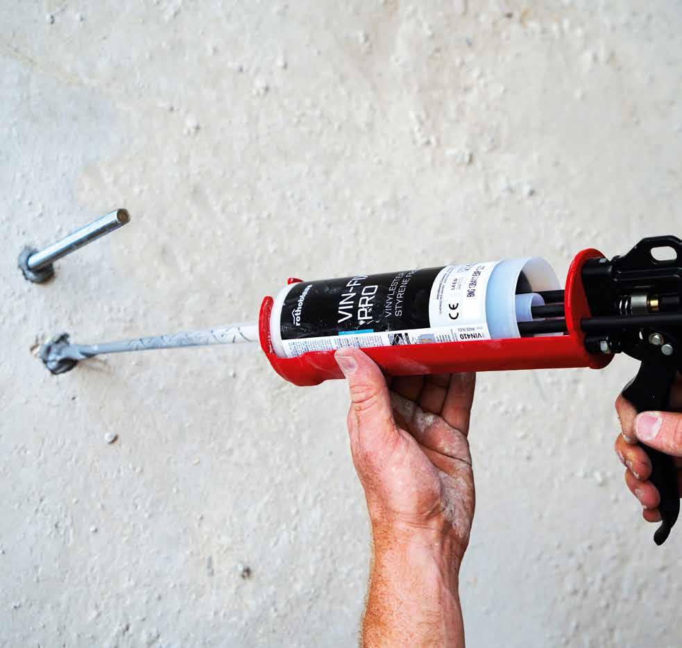
Single anchor point welded onto a bituminous layer for securing a flat roof.
TECHNICAL DATA*
ambient temperature of use -
substrate material requirement -
substrate tensile strength ≥ 900N/50 mm (EN 12311-2)
min. -30° C / max. 90°C
ABB / SBS multilayer bitumen membrane with at least one polyester core PVC / polyester reinforced membrane
340 ± 20% N/50 mm
max. roof slope 15° 15° 15°
minimum surface around the anchor point (from the centre) 1,80 m
other substrate requirements
The substrate must be clean, free of dust, moss and algae. Of course, the substrate must be completely dry
2 m
1. Mechanically fastened (MF) with a minimum of 3 fasteners per m²
2. Ballasted with gravel at least 40 mm thick (approx. 60 kg/m²)
3. Partially glued (50% of total surface area) to a mechanically fixed bituminous roof waterproofing system
* The values indicated are derived from experimental tests carried out under the supervision of third party organisations according to the referenced standard. For a calculation report with minimum distances, according to the referenced normative requirements, the substructure must be verified by a qualified engineer before installation.
CODES AND DIMENSIONS
CODE material d 1 pcs [mm]
GLUEBIT glued anchor point for bitumen roof with swivel eyelet
700 1
GLUEPVC glued anchor point for PVC roofs
520 1
GLUEBITGRA gravel anchor system protection - 1
GLUEPVC
GLUEBIT
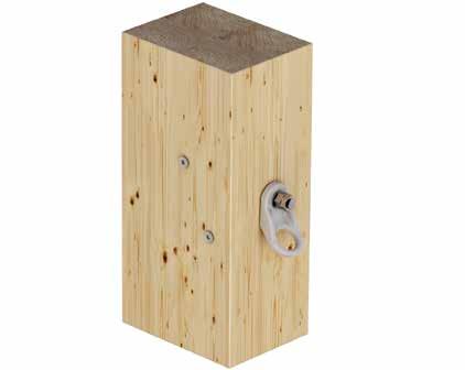
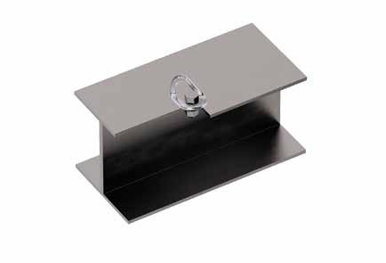
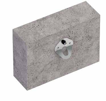
ANCHOR POINT
UNOBTRUSIVE
Very compact device that provides an anchorage point for an operator.
PRACTICAL
With its light weight, it is ideal as an anchor point for the safety rope during suspension work.
CODES AND DIMENSIONS
* The values indicated are the result of experimental tests carried out under the supervision of third parties in accordance with the standard referred to. For a calculation report with minimum distances according to the relevant standard requirements, the substructure must be checked by a qualified engineer before installation.
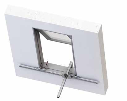
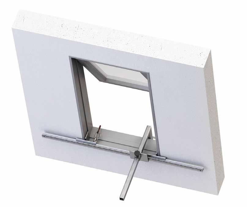
MOBILE
MOBILE ANCHOR POINT
REMOVABLE
It can be assembled and disassembled easily and quickly, to safely ensure temporary access to the roofing.
FUNCTIONAL
It can be temporarily installed on doors, windows and inclined skylights, with no structural damage.
CODES AND DIMENSIONS
The values indicated are the result of experimental tests carried out under the supervision of third parties in accordance with the standard referred to. For a calculation report with minimum distances according to the relevant standard requirements, the substructure must be checked by a qualified engineer before installation.
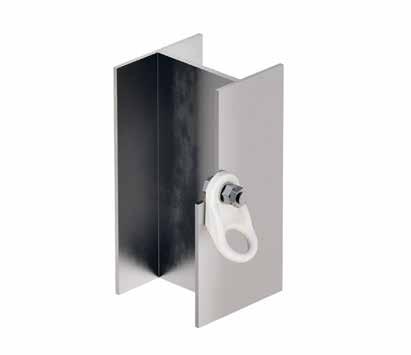
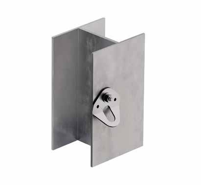
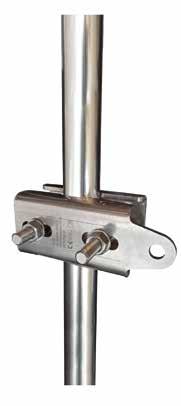
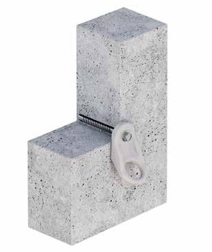
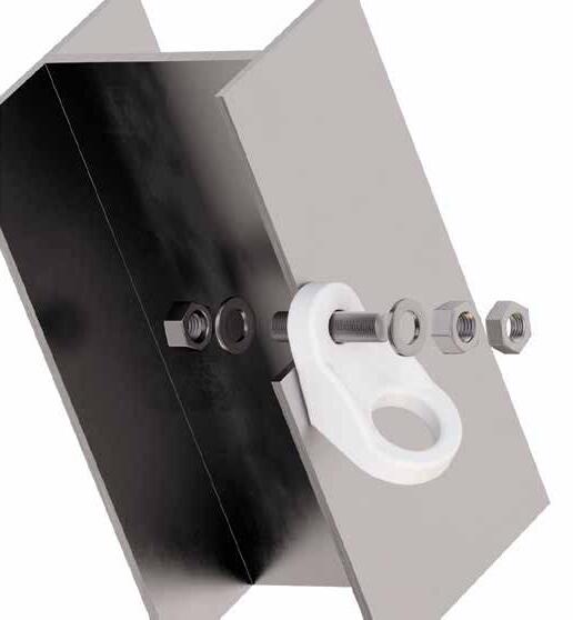
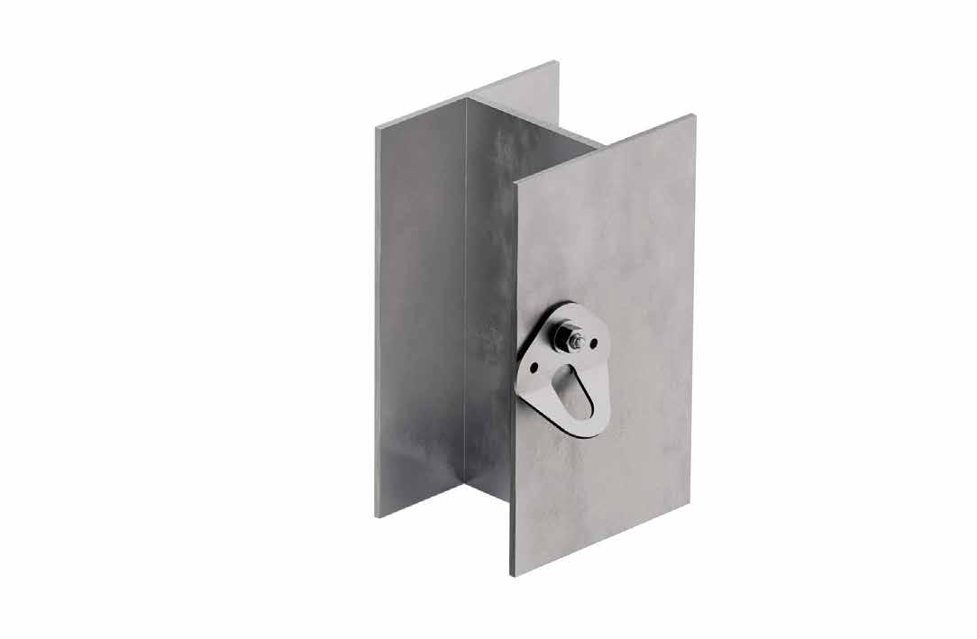
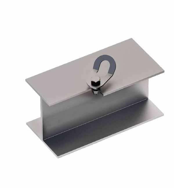
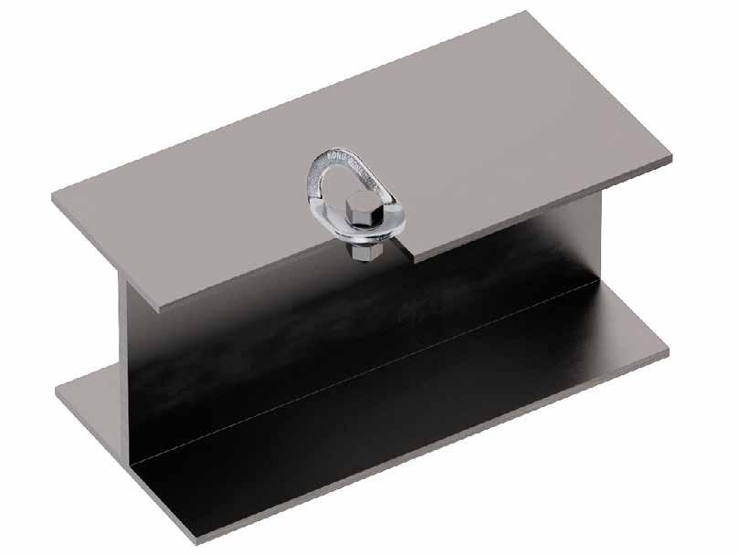
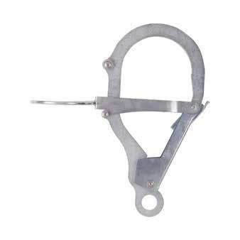
ANCHOR POINT FOR STEEL STRUCTURES
PRACTICAL
Thanks to its compact size, this anchor can be installed quickly and easily.
VERSATILE
It can be assembled on tubular and box-type steel structures of different sizes.
CODES AND DIMENSIONS
The values indicated are the result of experimental tests carried out under the supervision of third parties in accordance with the standard referred to. For a calculation report with minimum distances according to the relevant standard requirements, the substructure must be checked by a qualified engineer before installation.
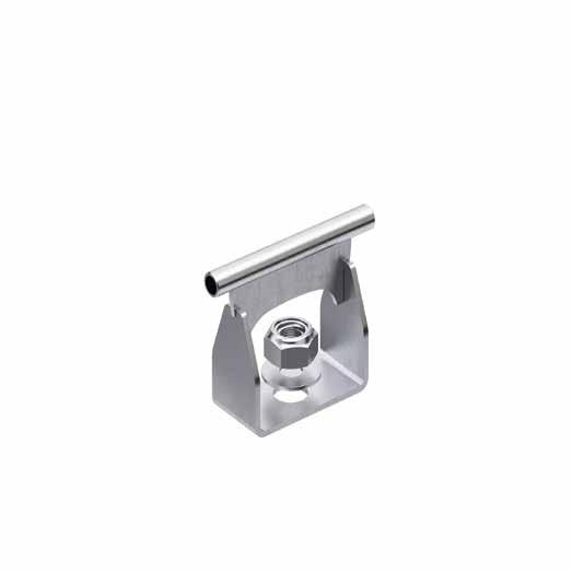
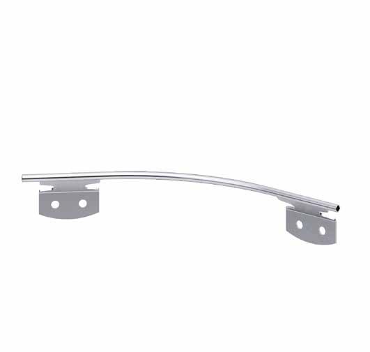
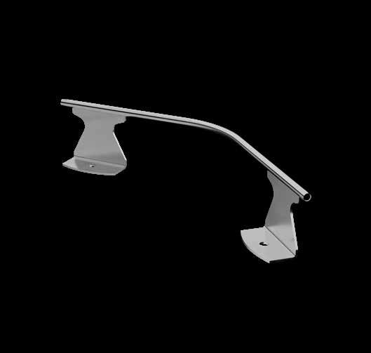
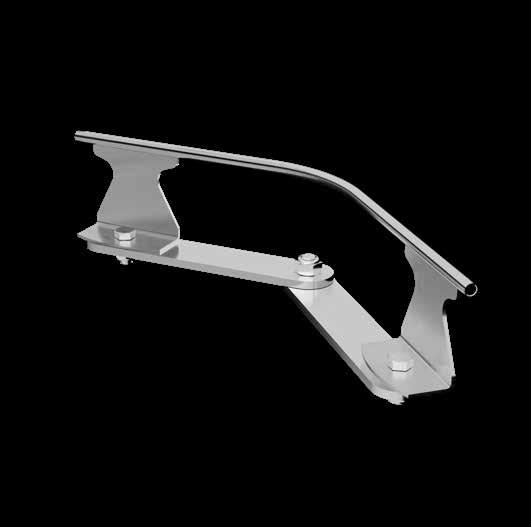
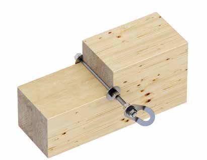
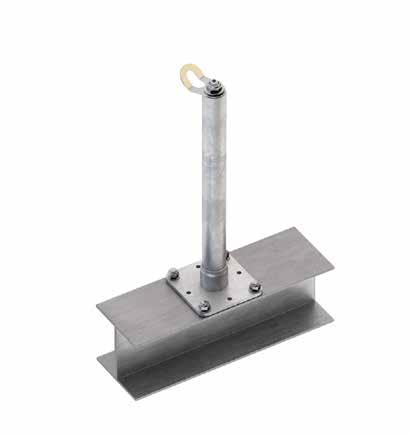
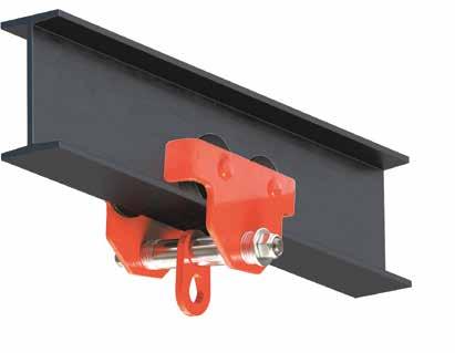
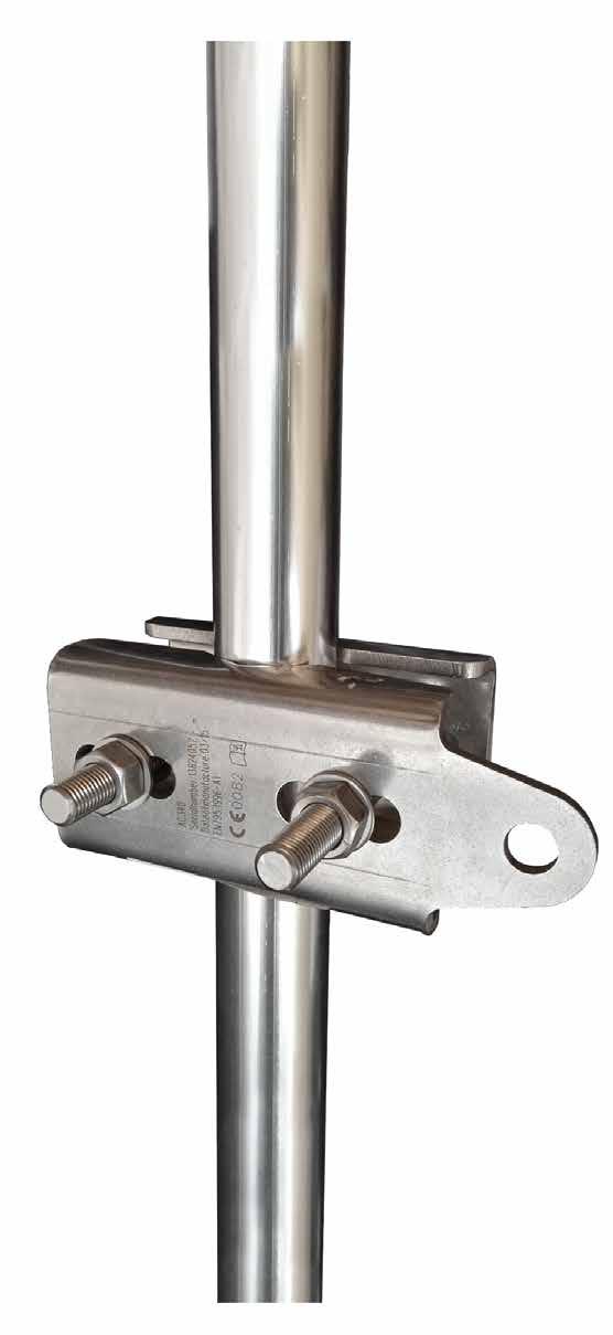
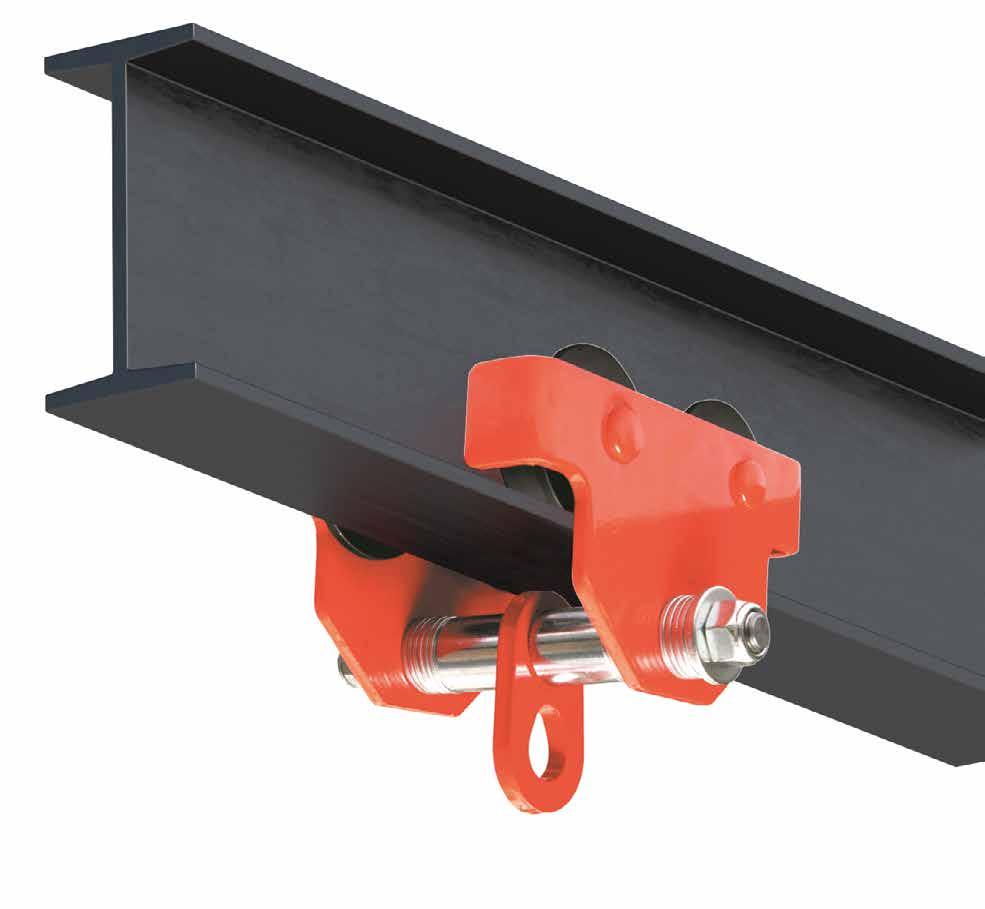
CARRIER ROD
SLIDING ANCHOR FOR STEEL STRUCTURES
FUNCTIONAL
Thanks to the integrated rollers, the device slides smoothly along the entire steel structure.
PRACTICAL
Quick and easy to install anchorage on steel beams with different widths, from 75 to 120 mm.
CODES
AND DIMENSIONS
The values indicated are the result of experimental tests carried out under the supervision of third parties in accordance with the standard referred to. For a calculation report with minimum distances according to the relevant standard requirements, the substructure must be checked by a qualified engineer before installation.
AOS01
ANCHOR POINT
FREEDOM OF MOVEMENT, SAFETY AND DURABILITY.
AOS01 is the universal device that allows you to make anchor points with all Rothoblaas supports. The 360° swivel eyelet provides total freedom of movement, ensuring reduced visual impact once installed on the roof. Completely made of stainless steel, AOS01 resists corrosion and atmospheric agents, maintaining its effectiveness over time.
AOS01 | overview
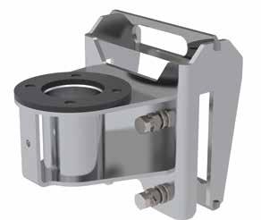
AOS01 + TOWER/TOWER
ANCHOR POINT FOR TIMBER, CONCRETE AND STEEL ROOFS
A2
AOS01 + SHIELD
ANCHOR POINT FOR TRAPEZOIDAL METAL ROOFS
AOS01 + SIANK 4
ANCHOR POINT FOR STANDING SEAM METAL ROOFS
AOS01 + COPPO
ANCHOR POINT FOR ROOFS WITH FAUX TILES
AOS01 + TOWER XL
ANCHOR POINT WITH INCREASED BOTTOM PLATE FOR TIMBER, STEEL AND CONCRETE ROOFS
AOS01 + SHIELD 2
ANCHOR POINT FOR TRAPEZOIDAL METAL ROOFS
AOS01 + SEAMO
ANCHOR POINT FOR ROUND SEAM METAL ROOFS
AOS01 + BLOCK
ANCHOR POINT WITH BALLAST FOR FLAT ROOFS
AOS01 + TOWER/TOWER A2
ANCHOR POINT FOR TIMBER, CONCRETE AND STEEL ROOFS
PRACTICAL
Support height is between 300 and 600 mm to adapt to different roofing thicknesses.
EFFECTIVE
Device with controlled deformation to limit load transfer to the structure.
UNOBTRUSIVE
Small-sized cylindrical system, minimizes the visual impact on the roofing.
point AOS01 installed on TOWER support for maintenance of industrial sheet metal roof.
Anchor
TECHNICAL DATA*
substructure minimum thickness fasteners
GL24h 160 x 160 mm VGS Ø9VGS AB7 CLT 200 mm VGS Ø9VGS AB7
S235JR 6 mm EKS+ULS+MUT EKS M10 +ULS+MUT substructure
AB1 Ø12 VGS AB7 M10 rod Ø12 AB7 M10 VIN VIN-FIX
HYB-FIX M10 VIN SKR CE
* The values indicated are the result of experimental tests carried out under the supervision of third parties in accordance with the standard referred to. For a calculation report with minimum distances according to the relevant standard requirements, the substructure must be checked by a qualified engineer before installation.
TOWER/TOWER A2 | CODES AND DIMENSIONS
TOWER300 S235JR zinc plated steel
TOWERA2300 AISI 304 stainless steel grade 1.4301
TOWER400 S235JR zinc plated
TOWERA2400 AISI 304 stainless steel grade 1.4301
TOWER500 S235JR
AOS01 AISI 304 stainless steel grade 1.4301 -
COMPLEMENTARY PRODUCTS CODE
AOS01 + TOWER XL
ANCHOR POINT WITH INCREASED BOTTOM PLATE FOR TIMBER, STEEL AND CONCRETE ROOFS
PRACTICAL
Support height between 300 and 800 mm to adapt to different roofing thicknesses.
SAFE
The enlarged bottom plate allows for the distribution of actions resulting from the anchoring devices over a wider area.
EFFECTIVE
Device with controlled deformation, it dissipates a part of the energy built up during a fall to limit the load transferred to the fastening and the structure.
Anchorage point AOS01 installed on TOWER XL support for maintenance of CLT flat roof.
TECHNICAL DATA*
* The values indicated are the result of experimental tests carried out under the supervision of third parties in accordance with the standard referred to. For a calculation report with minimum distances according to the relevant standard requirements, the substructure must be checked by a qualified engineer before installation.
TOWER XL | CODES AND DIMENSIONS
COMPLEMENTARY PRODUCTS
AOS01 + SHIELD
ANCHOR POINT FOR TRAPEZOIDAL METAL ROOFS
UNOBTRUSIVE
It ensures a reduced visual impact thanks to its small size.
PACKAGING
Supplied complete with mounting rivets and cellular rubber seals for perfect waterproofing.
TECHNICAL DATA*
* The values indicated are the result of experimental tests carried out under the supervision of third parties in accordance with the standard referred to. For a calculation report with minimum distances according to the relevant standard requirements, the substructure must be checked by a qualified engineer before installation.
SHIELD | CODES AND DIMENSIONS
AOS01 + SHIELD 2
ANCHOR POINT FOR TRAPEZOIDAL METAL ROOFS
FAST
Easy installation because it is configured as a single plate.
COMPLETE
The package includes fasteners and cellular rubber seals, to ensure waterproofing.
TECHNICAL DATA*
substructure
* The values indicated are the result of experimental tests carried out under the supervision of third parties in accordance with the standard referred to. For a calculation report with minimum distances according to the relevant standard requirements, the substructure must be checked by a qualified engineer before installation.
SHIELD 2 | CODES AND DIMENSIONS
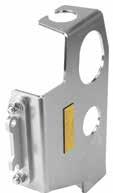
AOS01 + SIANK 4
ANCHOR POINT FOR STANDING SEAM METAL ROOFS
ROBUST
Fixed on two crimps for improved resistance.
HIGH PERFORMANCE
Up to four workers can be attached.
SAFETY
Installation does not require the sheet metal to be drilled, thanks to the gripper which distributes the load over the double seam, thus ensuring the integrity of the building envelope.
TECHNICAL
* The values indicated are the result of experimental tests carried out under the supervision of third parties in accordance with the standard referred to. For a calculation report with minimum distances according to the relevant standard requirements, the substructure must be checked by a qualified engineer before installation.
SIANK 4 | CODES AND DIMENSIONS
AOS01 + SEAMO
ANCHOR POINT FOR ROUND SEAM METAL ROOFS
SIMPLE
Fastened to the seam with four clamps, without the need to make openings in the sheet metal.
ROBUST
Fixed on two round crimps for improved resistance.
TECHNICAL DATA*
ALUFALZ, INTERFALZ, BEMO ROOF, KALZIP
ALUFALZ, INTERFALZ, BEMO ROOF, KALZIP
* The values indicated are the result of experimental tests carried out under the supervision of third parties in accordance with the standard referred to. For a calculation report with minimum distances according to the relevant standard requirements, the substructure must be checked by a qualified engineer before installation.
SEAMO | CODES AND DIMENSIONS
AOS01 + COPPO
ANCHOR POINT FOR ROOFS WITH FAUX TILES
FAST
Easy installation because it is configured as a single plate.
COMPLETE
The package includes fasteners and cellular rubber seals, to ensure waterproofing.
TECHNICAL DATA*
* The values indicated are the result of experimental tests carried out under the supervision of third parties in accordance with the standard referred to. For a calculation report with minimum distances according to the relevant standard requirements, the substructure must be checked by a qualified engineer before installation.
COPPO | CODES AND DIMENSIONS
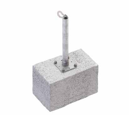
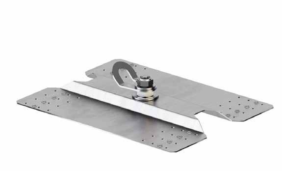
AOS01 + BLOCK
ANCHOR POINT WITH BALLAST FOR FLAT ROOFS
WITHOUT PERFORATIONS
It is designed for installation on flat roofs, and does not require to drill the roof covering, avoiding thermal bridges and preserving the waterproofing layer of the structure.
FLAT ROOFS
Designed for flat roofs with inclines up to 5° with PVC or bituminous final covering, with or without gravel.
BLOCK | CODES AND DIMENSIONS
* The values indicated are the result of experimental tests carried out under the supervision of third parties in accordance with the standard referred to. For a calculation report with minimum distances according to the relevant standard requirements, the substructure must be checked by a qualified engineer before installation.
COLLECTIVE PROTECTION
GUARD
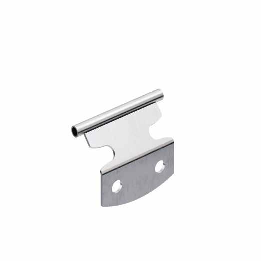
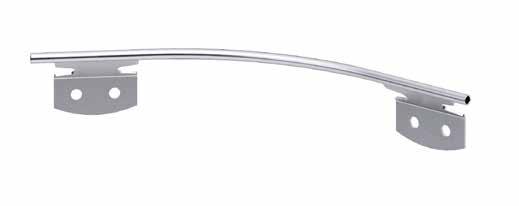
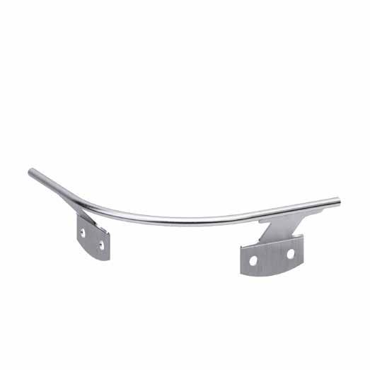
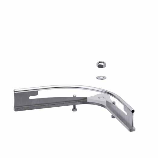
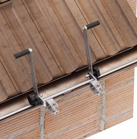
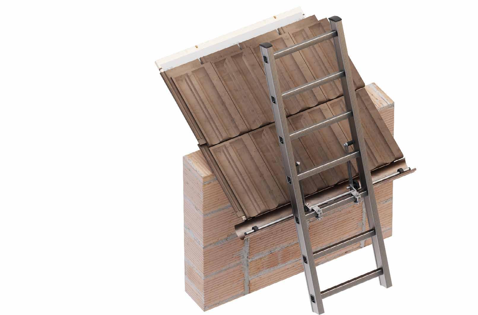
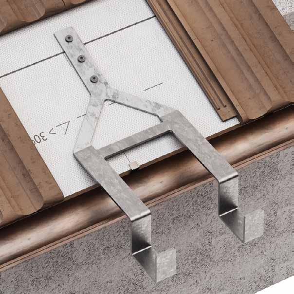
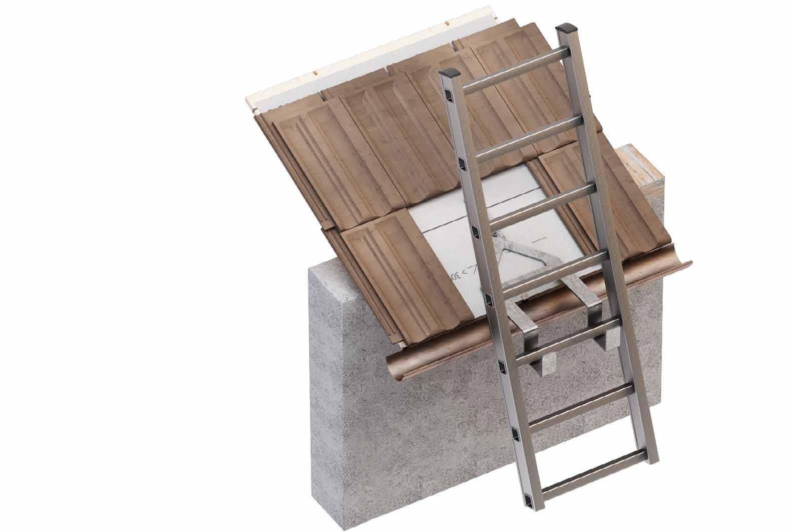
LADDER HOOKS
LADDERS
COLLECTIVE PROTECTIVE EQUIPMENT AND ACCESSES
COLLECTIVE PROTECTIVE EQUIPMENT
Collective Protective Equipment (CPE) are aimed at safeguarding people's health and safety The use of CPE should be seen as a priority with respect to the the use of Personal Protective Equipment (PPE)
PERMANENT RAILING BARRIERS
Permanent protections protect everyone who climbs on roofs from falls Workers can move freely without PPE when permanent railings are installed Compliant with standards EN 14122-3
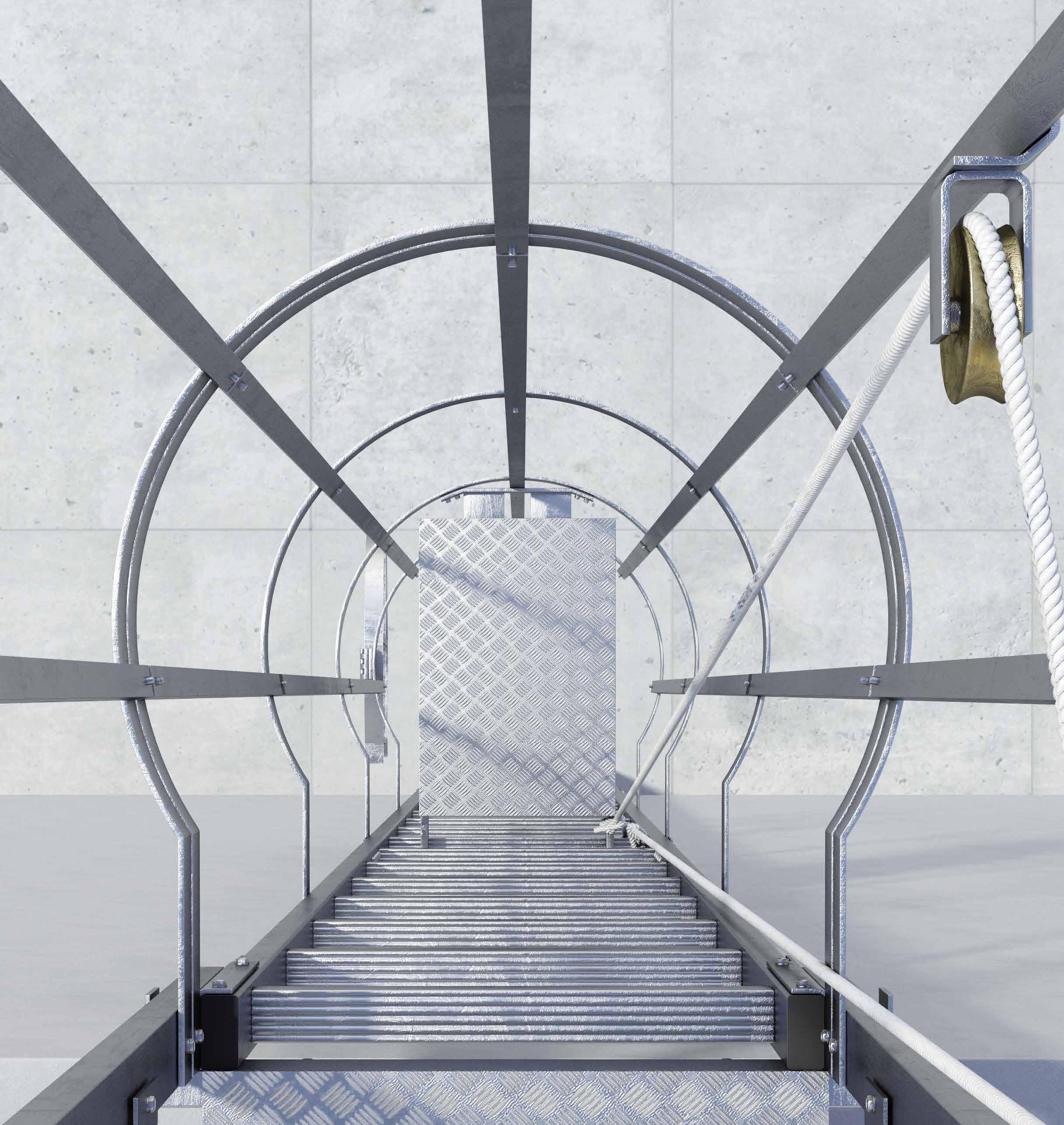
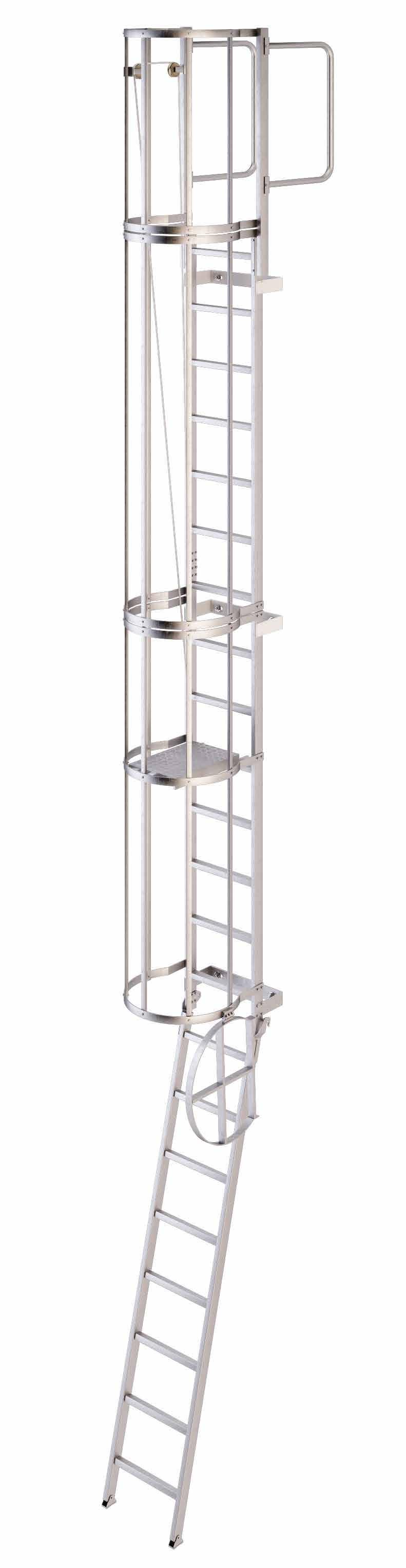
FIXED LADDERS
Ladders for safe access to workplaces at height, with or without cage Versions without a cage can be combined with the VERTIGRIP vertical lifeline system All ladders are designed according to Legislative Decree 09/04/2008 no 81 "Testo Unico" and according to EN 14122-4
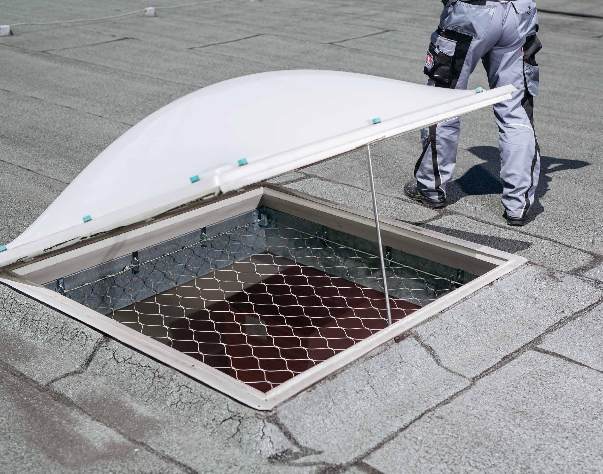
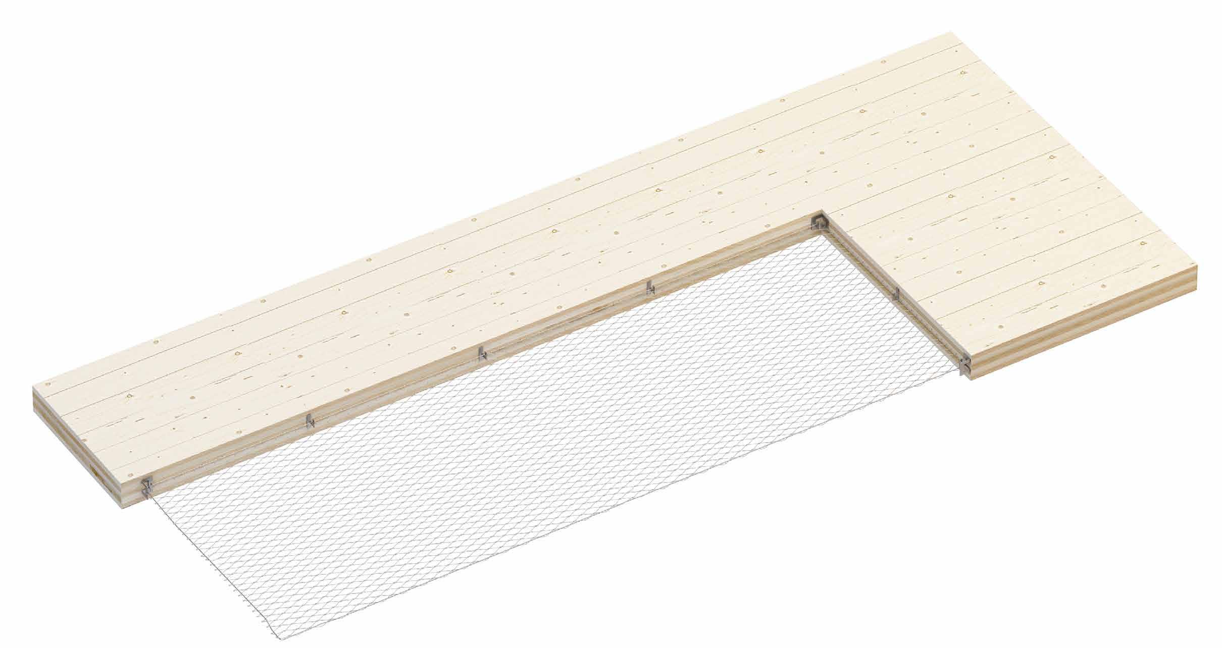
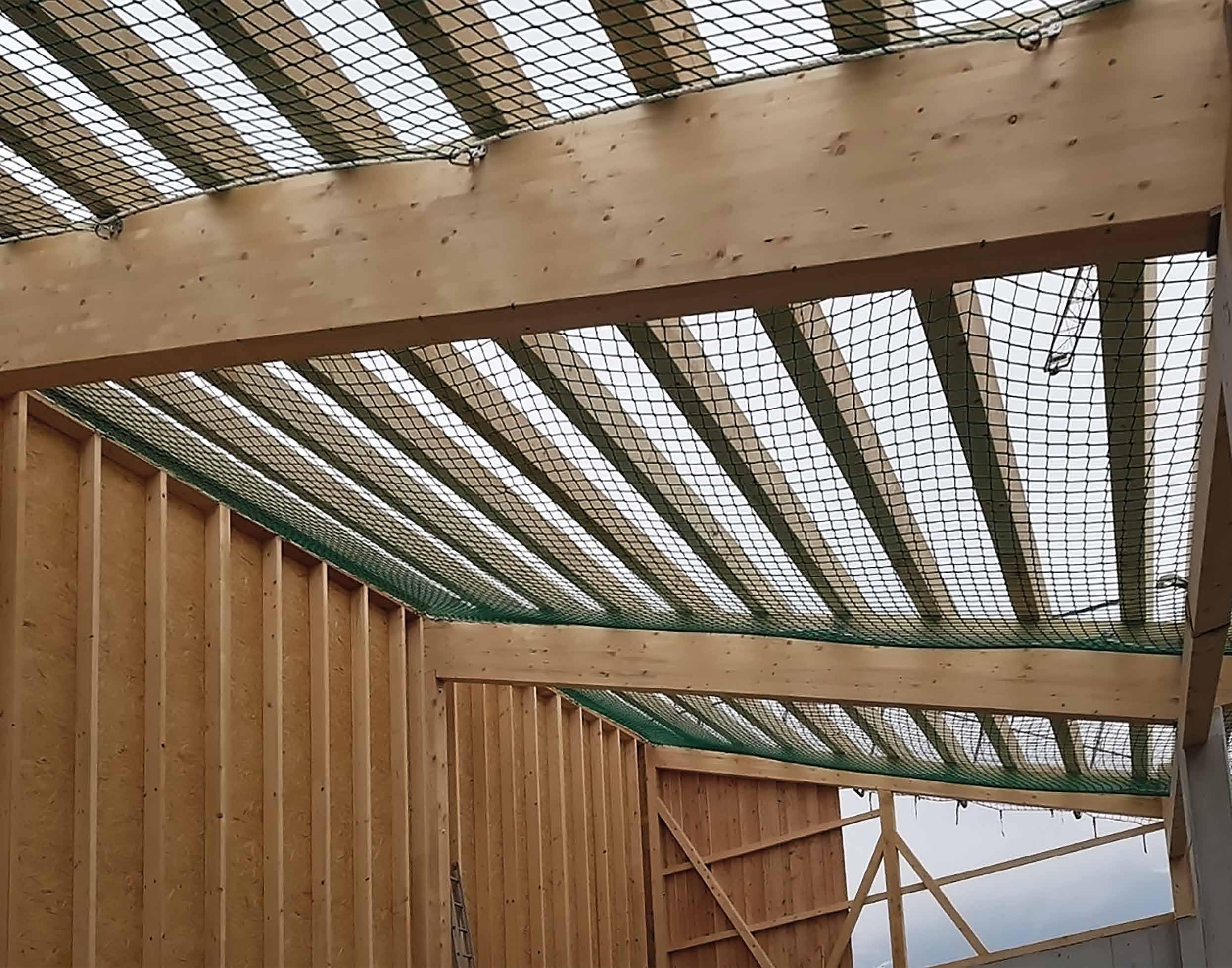
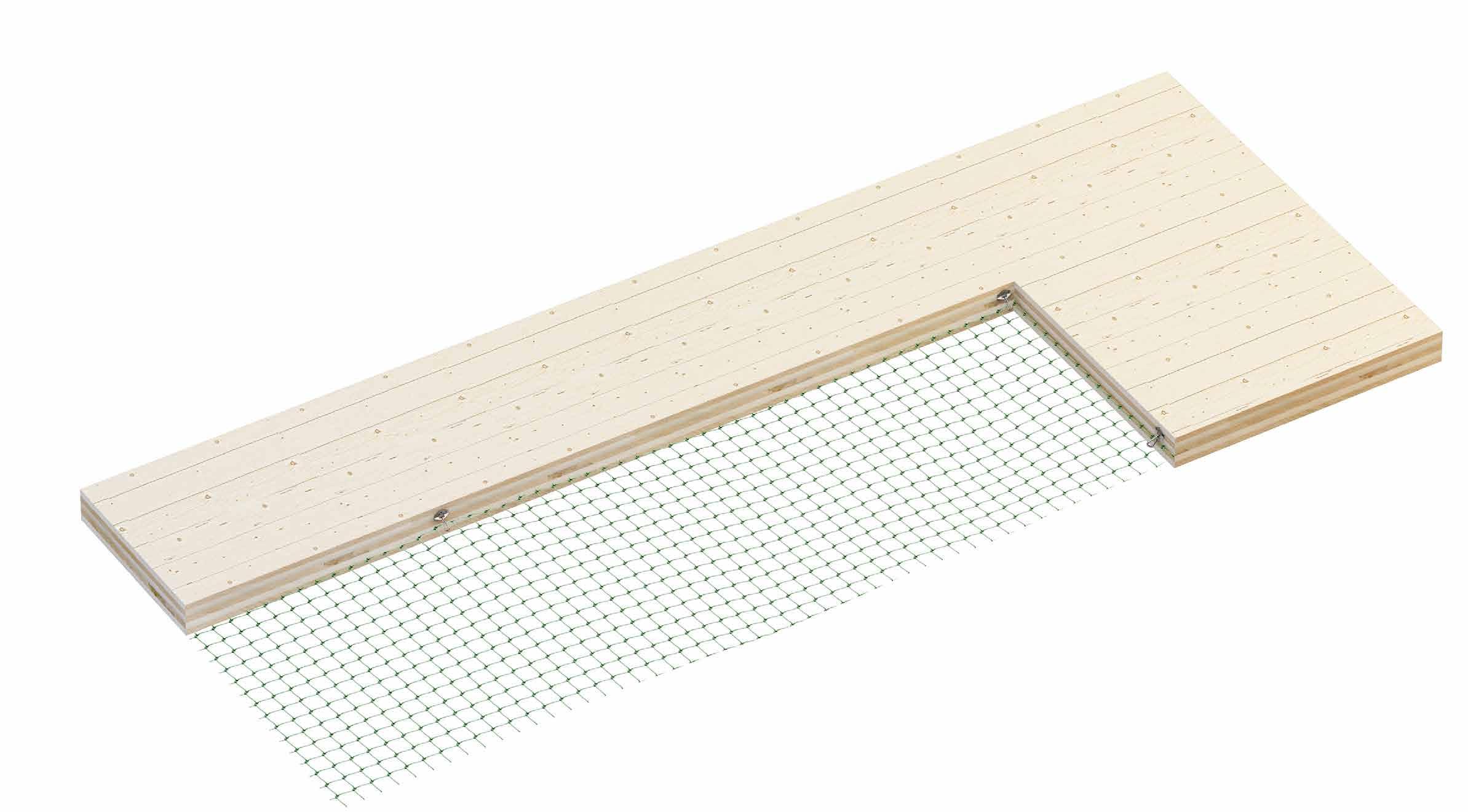
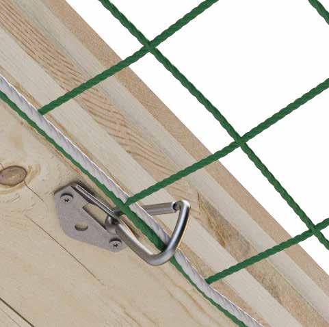
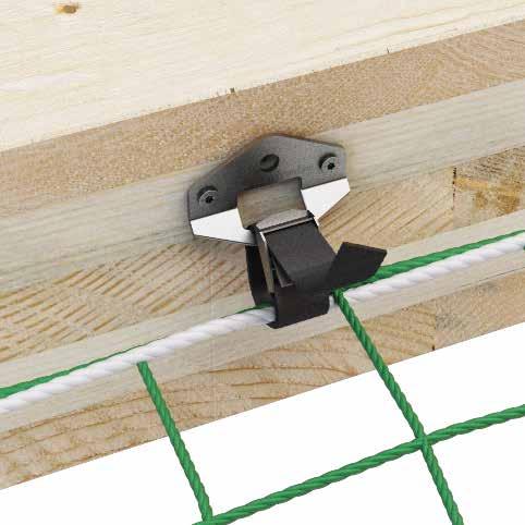
PERMANENT FALL PROTECTION NET
They protect workers from falling inside the building and are permanently mounted
ACCESSES
The term "access" identifies a point, that can be reached via a path allowing the safe transfer of one or more operators, materials and tools to the roofing
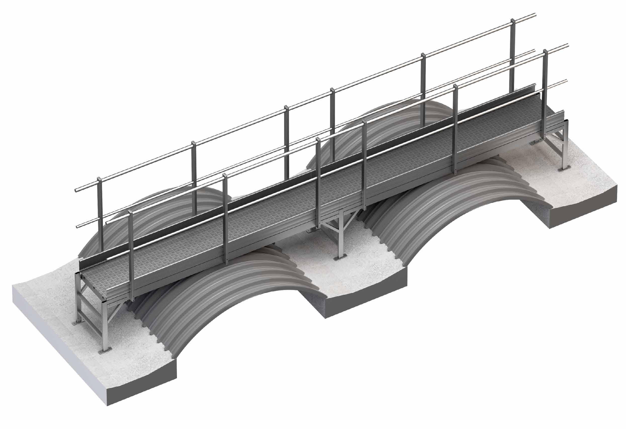
WALKWAYS AND OVERPASSES
TEMPORARY RAILING BARRIERS
LADDER HOOKS
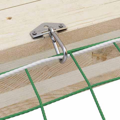
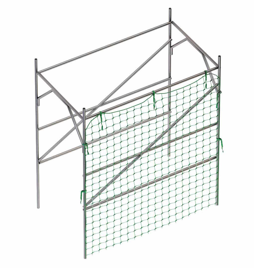
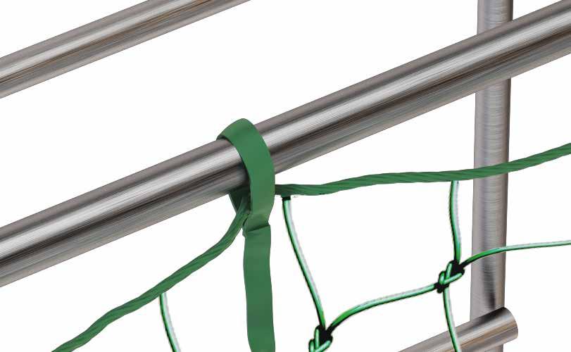
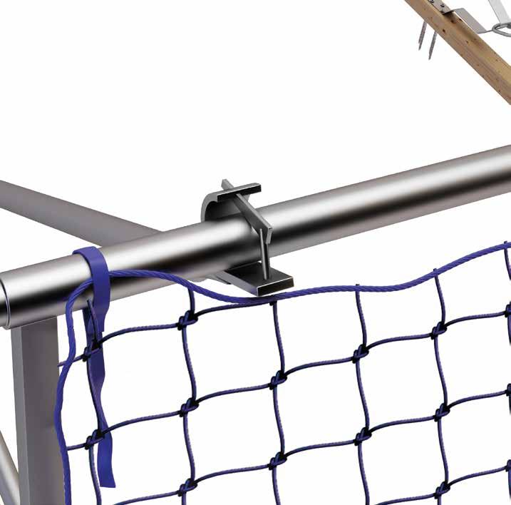
TEMPORARY FALL PROTECTION NETS
Walkways that allow to create safe routes on fragile roofs and overcome obstacles These systems comply with EN 14122-2 and EN 14122-3
Temporary protection against falls from height during installation and maintenance work Compliant with standard 13374
Ladder hooks are designed to prevent portable ladders from sliding sideways and frontally Ideal for use where there is no internal access to the roof
Fall protection nets for maintenance workers and technicians They offer freedom of movement and absorb the impact in the event of a fall
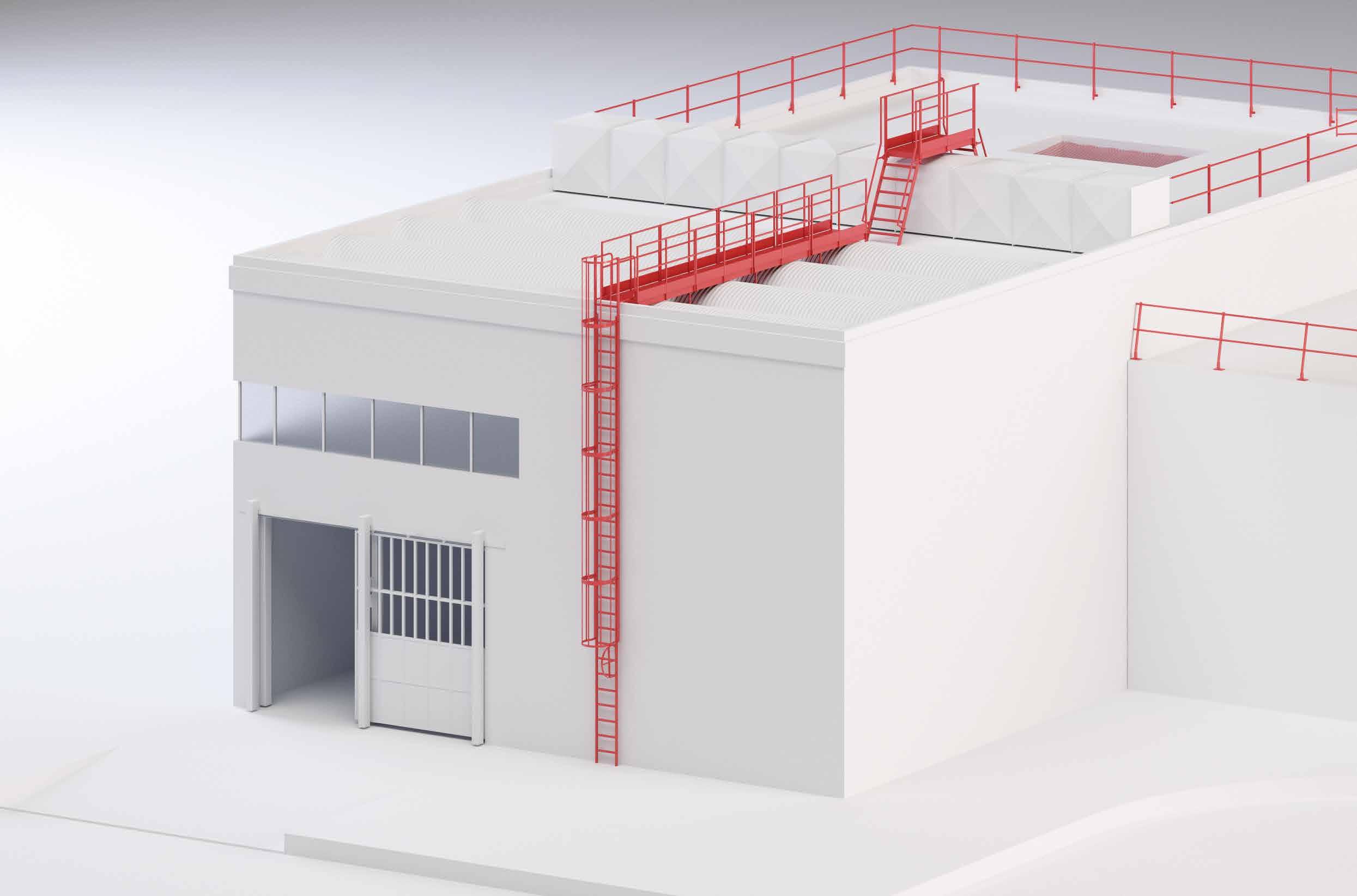
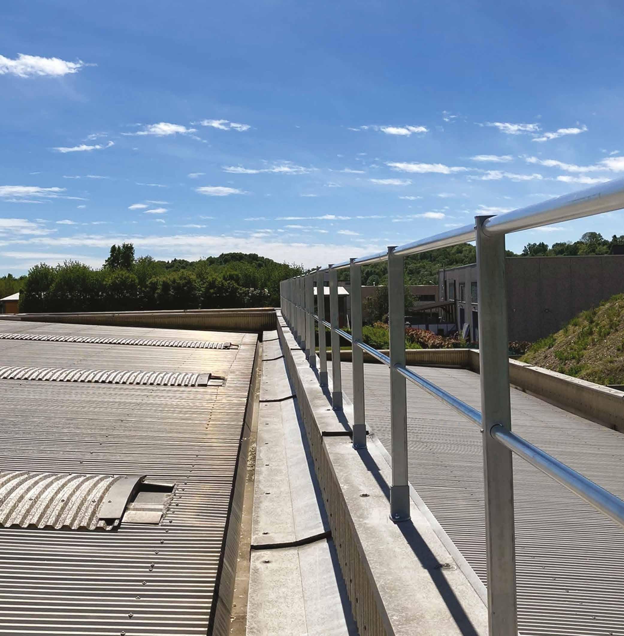
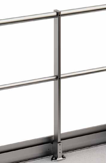
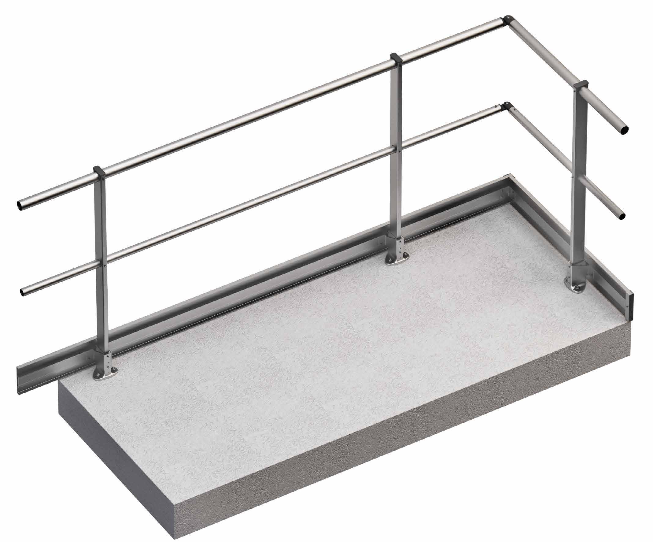
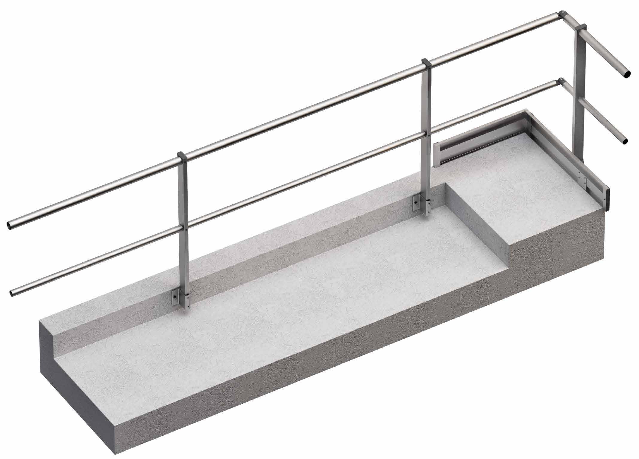
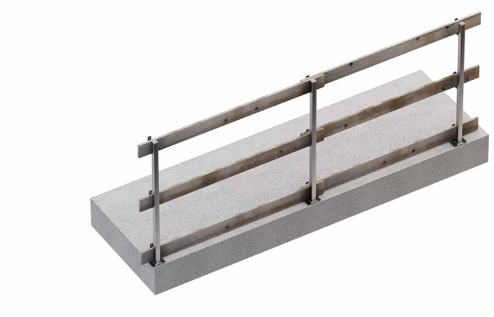
GUARD
PERMANENT ALUMINIUM RAILINGS
SIMPLE
Fast and easy to assemble, installation only takes a few steps
COMBINABLE
Modular system, can meet any design requirement thanks to the wide range of available accessories
AESTHETICS AND DURABILITY
The aluminium alloy guarantees an aesthetic system and good corrosion resistance in the long term
Installation of permanent railings for securing an industrial roof.
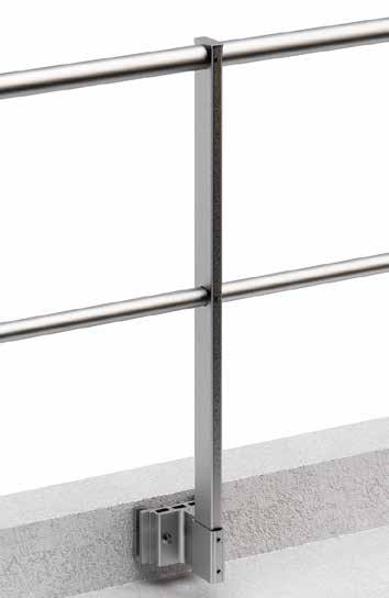
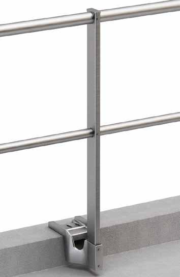
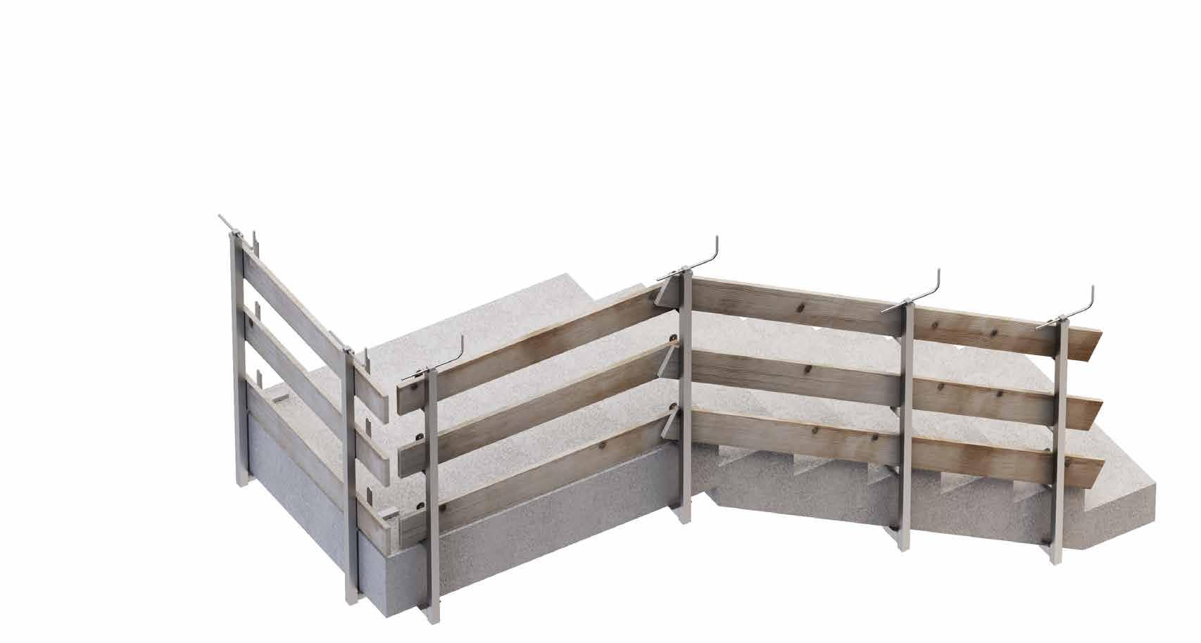
GUARD H HORIZONTAL FASTENING
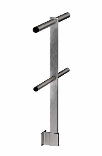
GUARD V/GUARD VD VERTICAL SPACED
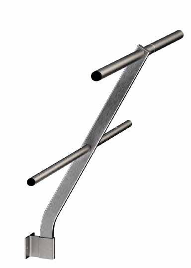
TYPES OF UPRIGHTS
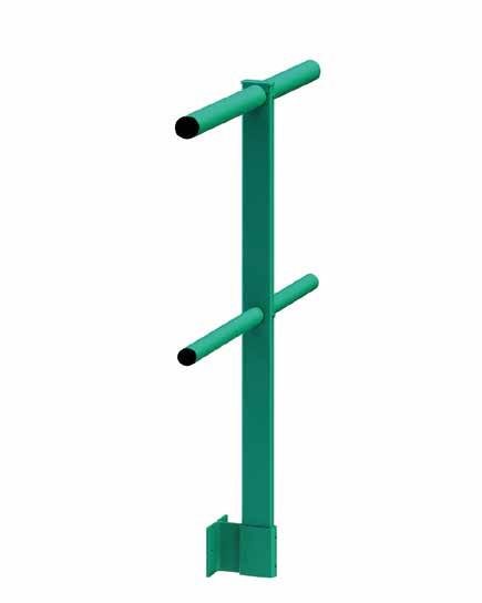
STRAIGHT UPRIGHT - S
* On demand.
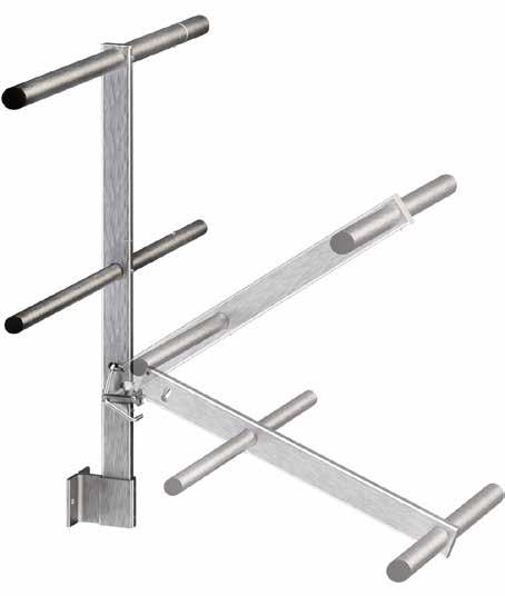
INCLINED UPRIGHT - I
SPACING BY TYPE OF FASTENER
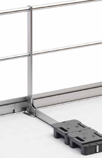
GUARD W SELF-SUPPORTING
Z GUARD Z SHAPED BASE (FASTENING)
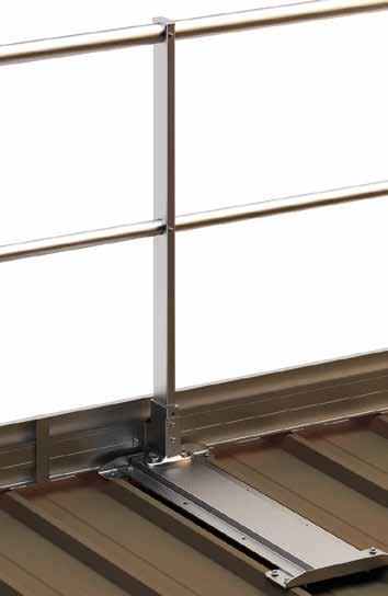
GUARD M ON METAL SHEET/METAL PANEL
FOLDING UPRIGHT - F*
Material: EN AW-6063 aluminium, anodised or powder-coated on request (RAL colours)
SPACING FOR UPRIGHT Hmax = 118
GUARD H
GUARD V - VD
GUARD W
GUARD Z
RAILING WITH TOE BOARD RAILING WITHOUT TOE BOARD
HORIZONTAL FASTENING RAILING
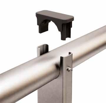
CODE description
1 RBGBAR45 Ø45 mm handrail with flush-mounted ring nuts L = 3000 mm
2 RBGBAR35 Ø35 mm intermediate rail with flush-mounted ring nuts L = 3000 mm
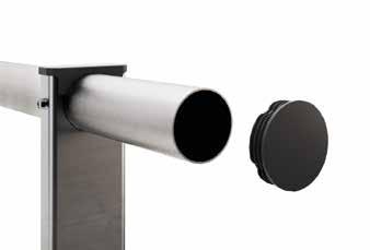
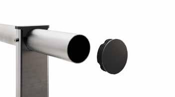
3 RBGCAP45 cap for handrail Ø45 mm
4 RBGCAP35 cap for intermediate rail Ø35 mm
5 RBGCOR45 angle bracket for handrail Ø45 mm
6 RBGCOR35 angle bracket for intermediate rail Ø35 mm
5-6 RBGCORAL aluminium angle bracket for handrail and intermediate rail (alternative to RBGCOR45/ RBGCOR35)
7 RBGBASEH bottom plate horizontal fastening painted grey GUARD H with grub screws included
CODE description
9 RBGCAP upright cap 68 x 28 mm groove Ø45 mm
10 RBGSCR4825 stainless steel self-drilling screw 4,8 x 25 mm
11 RBGSCR810 grub screw M8 x 10 mm (spare part)
12 RBGTB toe board 3000 x 150 x 19 mm
13 RBGTBCAP cap for toe board H = 150 mm
14 RBGTBJUN straight connector toe board H = 150 mm
15 RBGTBCOR angle bracket for toe board H = 150 mm
16 RBGTBH support for toe board H = 150 mm
17 RBGSCR4816 stainless steel self-drilling screw 4,8 x 16 mm
For wall fastening:
RBGWALL45 end element for handrail Ø45 mm
RBGSUP118 straight upright H = 1182 mm groove Ø45 mm
8 RBGSUP110 straight upright H = 1105 mm groove Ø45 mm
RBGSUP115I inclined upright H = 1157 mm groove Ø45 mm
RBGBASEHKIT waterproofing kit for GUARD H base
RBGWALL35 end element for round intermediate rail Ø35 mm
RBGWALLAL aluminium end element for handrail and intermediate rail
GUARD V/GUARD VD
RAILING VERTICAL AND VERTICAL SPACED FASTENING
CODE description
1 RBGBAR45 Ø45 mm handrail with flush-mounted ring nuts L = 3000 mm
2 RBGBAR35 Ø35 intermediate rail with flush-mounted ring nuts L = 3000 mm
3 RBGCAP45 cap for handrail Ø45 mm
4 RBGCAP35 cap for intermediate rail Ø35 mm
5 RBGCOR45 angle bracket for handrail Ø45 mm
6 RBGCOR35 angle bracket for intermediate rail Ø35 mm
5-6 RBGCORAL aluminium angle bracket for handrail and intermediate rail (alternative to RBGCOR45/ RBGCOR35)
7 RBGBASEV bottom plate for wall fastening GUARD V
RBGBASEVD bottom plate for fastening on projecting wall GUARD VD
8 RBGSUP118 straight upright H = 1182 mm groove Ø45 mm
RBGSUP130 straight upright H = 1300 mm groove Ø45 mm
9 RBGCAP upright cap 68 x 28 mm groove Ø45 mm
CODE description 10
stainless steel self-drilling screw 4,8 x 16 mm
stainless steel self-drilling screw 4,8 x 32 mm
RBGTB toe board 3000 x 150 x 19 mm
RBGTBCAP cap for toe board H = 150 mm
RBGTBJUN straight connector toe board H = 150
RBGTBCOR angle bracket for toe board H = 150 mm
RBGSUP115I inclined upright H = 1157 mm groove Ø45 mm
RBGDIST spacer element GUARD V-VD + 35 mm
For wall fastening:
RBGWALL45 end element for handrail Ø45 mm
RBGWALL35 end element for round intermediate rail Ø35 mm
RBGWALLAL aluminium end element for handrail and intermediate rail
GUARD W
SELF-SUPPORTING RAILING
CODE description
1 RBGBAR45 Ø45 mm handrail with flush-mounted ring nuts L = 3000 mm
2 RBGBAR35 Ø35 intermediate rail with flush-mounted ring nuts L = 3000 mm
3 RBGCAP45 cap for handrail Ø45 mm
4 RBGCAP35 cap for intermediate rail Ø35 mm
5 RBGCOR45 angle bracket for handrail Ø45 mm
6 RBGCOR35 angle bracket for intermediate rail Ø35 mm
5-6 RBGCORAL aluminium angle bracket for handrail and intermediate rail (alternative to RBGCOR45/ RBGCOR35)
7 RBGBASEW base for self-supporting GUARD W straight with support leg
8 RBGBASEWE locking wedge for GUARD W
RBGBASEWI base for self-supporting GUARD W inclined with support leg
9 RBGWEIGHT plastic counterweight 12,5 kg for GUARD W
For wall fastening:
RBGWALL45 end element for handrail Ø45 mm RBGWALL35 end element for round intermediate rail Ø35 mm
RBGWALLAL aluminium end element for handrail and intermediate rail
GUARD Z
A Z FASTENING RAILING
CODE description
1 RBGBAR45 Ø45 mm handrail with flush-mounted ring nuts L = 3000 mm
2 RBGBAR35 Ø35 intermediate rail with flush-mounted ring nuts L = 3000 mm
3 RBGCAP45 cap for handrail Ø45 mm
4 RBGCAP35 cap for intermediate rail Ø35 mm
5 RBGCOR45 angle bracket for handrail Ø45 mm
6 RBGCOR35 angle bracket for intermediate rail Ø35 mm
5-6 RBGCORAL aluminium angle bracket for handrail and intermediate rail (alternative to RBGCOR45/ RBGCOR35)
7 RBGBASEZ standard aluminium base Z for perimeter wall without insulation GUARD Z with grub screws included
CODE description
11 RBGSCR810 grub screw M8 x 10 mm (spare part)
For wall fastening:
RBGWALL45 end element for handrail Ø45 mm
RBGWALL35 end element for round intermediate rail Ø35 mm
RBGWALLAL aluminium end element for handrail and intermediate rail
8 RBGSUP110 straight upright H = 1105 mm groove Ø45 mm
9
RBGSUP118 straight upright H = 1182 mm groove Ø45 mm
RBGSUP115I inclined upright H = 1157 mm groove Ø45 mm
RAILING FASTENING ON TRAPEZOIDAL METAL ROOF
CODE description
1 RBGBAR45 Ø45 mm handrail with flush-mounted ring nuts L = 3000 mm
2 RBGBAR35 Ø35 intermediate rail with flush-mounted ring nuts L = 3000 mm
3 RBGCAP45 cap for handrail Ø45 mm
4 RBGCAP35 cap for intermediate rail Ø35 mm
5 RBGCOR45 angle bracket for handrail Ø45 mm
6 RBGCOR35 angle bracket for intermediate rail Ø35 mm
5-6 RBGCORAL aluminium angle bracket for handrail and intermediate rail (alternative to RBGCOR45/RBGCOR35)
RBGBASE250PE plate for fastening to trapezoidal sheet metal, pitch 250 mm, perpendicular to the frets (excluding screws)
CODE description
RBGSUP110 straight upright H = 1105 mm groove Ø45
8
stainless steel self-drilling screw 4,8 x 25 mm
7a
RBGBASE333PE plate for fastening to trapezoidal sheet metal, pitch 333 mm, perpendicular to trapezoidal sheet metal (excluding screws)
RBGBASE250PA plate for fastening to trapezoidal sheet metal, pitch 250 mm, parallel to trapezoidal sheet metal (excluding screws)
7b
RBGBASE333PA plate for fastening to trapezoidal sheet metal, pitch 333 mm, parallel to trapezoidal sheet metal (excluding screws)
For wall fastening: RBGWALL45 end element for handrail Ø45 mm RBGWALL35 end element for round intermediate rail Ø35 mm RBGWALLAL
GUARD | components
CODES AND DIMENSIONS
GROUP CODE description
RBGBAR45 Ø45 mm handrail with flush-mounted ring nuts L = 3000 mm
RBGBAR35 Ø35 intermediate rail with flush-mounted ring nuts L = 3000 mm 1
COD: 24002
COD: 03931
HANDRAILS AND INTERMEDIATE RAILS
UPRIGHTS
RBGBAR45F handrail without flush-mounted ring nuts Ø45 mm L = 3000 mm
RBGBAR35F handrail without flush-mounted ring nuts Ø35 mm L = 3000 mm
RBGCAP upright cap 68 x 28 mm groove Ø45 mm
RBGSUP100 straight upright H = 1028 mm groove Ø45 mm 1
RBGSUP110 straight upright H = 1105 mm groove Ø45 mm
RBGSUP118 straight upright H = 1182 mm groove Ø45 mm
RBGSUP110F pull-down upright H = 1105 mm groove Ø45 mm
RBGSUP100F pull-down upright H = 1010 mm groove Ø45 mm
RBGSUP130 straight upright H = 1300 mm groove Ø45 mm
RBGSUP115I inclined upright H = 1157 mm groove Ø45 mm
COD: 23676
RBGSUP100F
TOE BOARD AND ACCESSORIES
RBGTB toe board 3000 x 150 x 19 mm
RBGTBJUN straight connector of toe board H = 150 mm
RBGTBCOR angle bracket for toe board H = 150 mm
RBGTBCAP cap for toe board H = 150 mm
RBGTBW support for toe board H = 150 mm for GUARD W
RBGTBH support for toe board H = 150 mm
COD: RBGTBJUN
COD: RBGTBCOR
COD: RBGTBCAP
COD: RBGTBW?
COD: RBGTBH
RBGBAR45F
RBGBAR35F
GUARD | components
CODES AND DIMENSIONS
GROUP CODE description
RBGBASEW base for self-supporting GUARD W straight with support leg
RBGBASEWI base for self-supporting GUARD W inclined with support leg
RBGBASEWFCR shank curved at right at 25° per angle
RBGBASEWFCL
RBGBASEWFR
STANDARD BASES
RBGBASEWE locking wedge for GUARD W (spare part)
RBGWEIGHT plastic counterweight 12,5 kg for GUARD W
RBGBASEV bottom plate for wall fastening GUARD V
RBGBASEVD bottom plate for fastening on projecting wall GUARD VD
RBGDIST spacer piece GUARD V-VD + 35 mm
RBGBASEH bottom plate horizontal fastening painted grey GUARD H
RBGBASEZ standard aluminium base Z for perimeter wall without insulation GUARD Z
COD: RBGBASEW
COD: RBGBASEWI
COD: RBGBASEWE
COD: RBGWEIGHT
COD: 02876
COD: RBGBASEVD
COD: RBGDIST
COD: RBGBASEH
COD: RBGBASEZ
CODES AND DIMENSIONS
GROUP CODE description
RBGBASE250PA plate for fastening to trapezoidal sheet metal, pitch 250 mm, parallel to trapezoidal sheet metal (excluding screws)
BASES FOR FASTENING ON TRAPEZOIDAL METAL ROOF
ACCESSORIES
RBGBASE333PA plate for fastening to trapezoidal sheet metal, pitch 333 mm, parallel to trapezoidal sheet metal (excluding screws)
RBGBASE250PE plate for fastening to trapezoidal sheet metal, pitch 250 mm, perpendicular to the frets (excluding screws)
RBGBASE333PE plate for fastening to trapezoidal sheet metal, pitch 333 mm, perpendicular to trapezoidal sheet metal (excluding screws)
RBGCAP45 cap for handrail Ø45 mm
RBGCAP35 cap for intermediate rail Ø35 mm
RBGCOR45 angle bracket for handrail Ø45 mm
RBGCOR35
RBGSCR4816
RBGSCR4825 RBGSCR4832
RBGSCR4832
FASTENING SCREWS
RBGSCR627
RBGSCRWAS
LADSTEP
CAGED LADDERS
DURABLE
Made of aluminium alloy, they offer high mechanical resistance and resist corrosion and environmental conditions
RELIABLE
Guarantee the utmost safety for the user and give the installer the serenity that comes with a reliable product that is easy to assemble
COMBINABLE
Thanks to the wide range of available components, the modular system can meet any design requirement
Aluminium ladder with landing platforms for access to industrial roof.
CODES OF BASIC COMPONENTS FOR FIXED CAGED/CAGELESS LADDERS
LADDER MODULES
CAGE BARS
RINGS
BRACKETS
+ LADSTRAP500
LADBRA550 + LADSTRAP550
LADBRA600 + LADSTRAP600
LADSTEP | accessory components
CODES OF ACCESSORY COMPONENTS FOR FIXED CAGED/CAGELESS LADDERS*
GROUP CODE description
HANDLES
LADHANDS kit of 2 landing handles 450 mm
INTERLOCKING EXTENSION
LADEXTMOB130 interlocking extension 1 30 m for easy access to the roof
LADLAND500 500 x 500 mm final landing platform, non-slip
LANDING PLATFORMS
LADLAND750 500 x 750 mm final landing platform, non-slip
PROTECTION KIT
LADPROT750 750 mm platform protection kit complete with 4 handrails, 2 aluminium toeboards
LADHANDS
FOLDING PLATFORMS
LADBOARIT folding or resting platform for ladder subdivision (with lifting and lowering system) Leg Decree 81/2008 Ø600 mm
LADBOAREU folding or resting platform for ladder subdivision (with lifting and lowering system) EN 14122-4 Ø700 mm
LADREST folding resting platform for ladder with lifeline
LADBOAREU
LADEXTMO0130
LANDALAND750
LADBOARIT
LADREST
GROUP CODE description
LADTRAPIT safety closure prepared for padlock (not included) Leg Decree 81/2008 Ø600 mm
SAFETY CLOSURES
LADTRAPEU safety closure prepared for padlock (not included) EN 14122-4 Ø700 mm
HOOKS FOR SEPARATE LADDER LADHOOK fastening hooks for separate ladder
FEET
LADFEREG kit of 2 adjustable support feets with holes for fastening to the ground
LADFEHIN kit of 2 hinged support feets
Screws, joints, caps always included in the single codes.
LADDER
COMPOSITION INDICATIONS
• Applicable regulations (Leg Decree 81/2008 - EN 14122-4 - local regulations) must be defined by the designer of the work
• Choice of components according to the regulations applied
• First ladder module with length of 2,4 m
• Cage start at 2,4 m
• First bracket at 0,5 m
• Subsequent brackets installed every 2,0 m
Other components are available on request For the composition, use the handbook or the component spreadsheet, both available on our website: www rothoblaas com
SAFENET
CUSTOMIZABLE HORIZONTAL FALL
PROTECTION NET
COMPLETE
Complete system with A4 stainless steel mesh, pre-assembled perimeter rope, brackets and fasteners included for all types of substructure
SIMPLE
Quick and easy assembly with the aid of corner and straight fastening systems
Anti-intrusion plate included
VERSATILE
Possibility of application to structures of various materials (timber, steel, concrete)
Installation of permanent fall protection safety net in A4 stainless steel for securing a skylight on a flat roof.
FIELDS
CODES AND DIMENSIONS
RANGE CODE description net surface (from A to B m 2)
SN01 stainless steel mesh A4 0 - 1 m2 from 0,00 to 1 00 m2
SN02 stainless steel mesh A4 1 - 2 m2 from 1 to 2 m2
SN03 stainless steel mesh A4 2 - 3 m2 from 2 to 3 m2
SN04 stainless steel mesh A4 3 - 4 m2 from 3 to 4 m2
SN05 stainless steel mesh A4 4 - 6 m2 from 4 to 6 m2
SN06 stainless steel mesh A4 6 - 10 m2 from 6 to 10 m2
SN07 stainless steel mesh A4 10 - 15 m2 from 10 to 15 m2
SN08 stainless steel mesh A4 surface over 15 m2 from 15 to M m2
MATERIAL ORDERING SCHEME
Example: skylight with steel structure 0,8 m x 1,2 m = 0,96 m 2
SN01 + M + 0080 + 0120
RANGE CODE surface fastening on: ( W ) wood (C) concrete (M) metal
Code created: SN01M00800120
< 450 < 450 < 450 L
A4 stainless steel mesh with fasteners for various substructures included Application of
Maximum distances to position the fastening brackets
HORIZONTAL FIXED FALL PROTECTION NET
ADJUSTABLE
Available in various sizes, to meet all needs of the construction site
TRANSPORTATION
Supplied in convenient rolls that facilitate transport and installation
EXISTING STRUCTURES
It can be installed on finished buildings without having to disassemble skylights
MODEL
MODEL
MODEL
WALKWAYS
WALKSAFE
WALKWAYS
RELIABLE
The non-slip, anti-oil, anti-heel and ice resistant coating ensures safe footing
STANDARD MODULES
Available in 1,50 and 3,0 m long modules, from 60 to 80 cm wide Additional sizes available upon request
MODULAR
Available with or without railing and toe boards, or single-sided Possibility to be fixed directly or with supports of various heights
CODES AND DIMENSIONS
WALKWAY MODULE
Other lengths available on request.
RAILING MODULE WITH OPTIONAL TOE BOARD*
Other lengths available on request.
*The code is for the single side.
RAISED END SUPPORTS
Other heights
RAISED INTERMEDIATE SUPPORTS
Other heights available on request.
OTHER SUPPORTS AND JOINTS
CODE description
WALKBASE base support for direct fastening/bracket for WALKMET
WALKJUN fastening joint for WALK module
Other components are available on request. For the composition, use the handbook or the component spreadsheet, both
WALKWAYS
OVERLANE
OVERPASS WALKWAY
LIGHT
Thanks to the prefabrication and lightness of aluminium, it can be easily transported and is simple to install
ADJUSTABLE
With various lengths and widths of both the landing platform and the side steps, it provides a solution for overcoming any obstacle
RELIABLE
The non-slip covering means difficult areas of roofs or machinery can be reached safely
SCAVALCHI
CODES AND DIMENSIONS
Other dimensions are available on request
SIDE STEPS WITH RAILING*
Other sizes are available on request *One on each side of the overpass
ACCESSORIES FOR OVERPASS
CODE description
OVERBAR ballast holder for self-supporting fastening
OVERWEIGHT 22 5 kg concrete ballast (2 for each OVERBAR support) LANDING WITH DOUBLE RAILING AND TOE BOARD
EXAMPLE OF A COMPOSITION FOR A COMPLETE OVERPASS: n 1OVERPLAT820 n 2 OVERSTEP812
If self-supporting with ballast add: no 4 OVERBAR no 8 OVERWEIGHT
Other components are available on request. For the composition, use the handbook or the component spreadsheet, both available on our website: www.rothoblaas.com.
TEMPORARY RAILING BARRIERS
EDGE TEMP 1
CODES AND DIMENSIONS*
TEMPORARY RAILING ROOF SIDE CODE standard material
* The values indicated are derived from experimental tests carried out under the supervision of third party organisations according to the referenced standard. For a calculation report with minimum distances, according to the referenced normative requirements, the substructure must be verified by a qualified engineer before installation.
EDGE TEMP 2
TEMPORARY RAILING FRONT COVER
CODES AND DIMENSIONS*
CODE
* The values indicated are derived from experimental tests carried out under the supervision of third party organisations according to the referenced standard. For a calculation report with minimum distances, according to the referenced normative requirements, the substructure must be verified by a qualified engineer before installation.
EDGE TEMP 3
TEMPORARY RAILING FOR HORIZONTAL EDGES
CODES AND DIMENSIONS*
EDGETEMP3 EN 13374 Class A zinc-plated steel the slope of the working surface (impact sound surface) must be less than 10°
* The values indicated are derived from experimental tests carried out under the supervision of third party organisations according to the referenced standard. For a calculation report with minimum distances, according to the referenced normative requirements, the substructure must be verified by a qualified engineer before installation.
EDGE TEMP 4
TEMPORARY UNIVERSAL RAILING WITH STEM
CODES AND DIMENSIONS*
EDGETEMP4 EN 13374 Class A zinc-plated steel the slope of the working surface (impact sound surface) must be less than 10°
* The values indicated are derived from experimental tests carried out under the supervision of third party organisations according to the referenced standard. For a calculation report with minimum distances, according to the referenced normative requirements, the substructure must be verified by a qualified engineer before installation.
LADDER HOOKS
HANG TEMP
MOBILE LADDER HOOK
CODES AND DIMENSIONS
HANG ROOF
LADDER HOOK FOR PITCHED ROOFS
CODES AND DIMENSIONS
HANG WALL
LADDER HOOK FOR WALL
CODES AND DIMENSIONS
HANG PLAIN
LADDER HOOK FOR FLAT SURFACES
CODES AND DIMENSIONS
HORIZONTAL NET
HORIZONTAL POLYPROPYLENE
FALL PROTECTION SAFETY NET
SAFE
It requires a limited number of fastening systems (maximum distance between anchors: 2 5 m)
MODULAR
Possibility of joining several nets together using HORCONNECT sewing rope to cover larger areas
CAN BE PERSONALIZED
Also available in other colours by request (red, blue, white) and in personalised format for specific net sizes
Installation of temporary polypropylene fall protection nets for securing a timber roof under construction
CODES AND DIMENSIONS
COMPLEMENTARY PRODUCTS
FASTENING FOR HORHOOKU
VERTICAL NET
VERTICAL POLYPROPYLENE
FALL PROTECTION SAFETY NET
SAFE
Protection system for roof edges and scaffolding
FUNCTIONAL
Installation by inserting each individual link in the scaffold pipe or via fastening straps (optional)
VERSATILE
Also available in other colours by request (red, blue, white)
CODES AND DIMENSIONS
COMPLEMENTARY PRODUCTS
FRAME NET
FALL PROTECTION SAFETY NET WITH FRAME
FUNCTIONAL
Possibility of installation on roofs with an inclination of up to 60°
FAST
Quick and easy assembly thanks to the few modular components
VERSATILE
Ideal for securing the roof when there is no possibility of installing external scaffolding or perimeter protection with external fastening
CODES AND DIMENSIONS
The distance between the fastening brackets is max 2 4 m Each first module of the protection system (near each falling edge) must be fixed with two brackets and two supports, all other modules assembled next to each other and secured with quick fastening straps are fixed with only one support and fastening bracket
PERSONAL PROTECTIVE EQUIPMENT
PPE STANDARDS
FALL PROTECTION AND POSITIONING ROPES AND ACCESSORIES
RETRACTABLE DEVICES - EN 397 ANSI Z.89.1 EN 166 EN 352-3 EN 50365
361 EN 358 EN 813 EN 12275/A/C ANSI/ASSE Z359.112014
EQUIPMENT CARE AND MAINTENANCE
TEXTILE DEVICES
CUTS
A 2-mm edge cut reduces facric resistance by up to 40%
ULTRA VIOLET DEGRADATION
The sun and welding can damage textile components
ABRASIONS
An abrasion on textile components acts just like a cut when fabric threads are torn
SEAMS
Before each use it is essential to check that there are no loose, torn, worn or missing threads
BURNS
Caused both by heat sources and by contact with chemical and corrosive substances or materials In particular, nylon is usually damaged when in contact with acids, and polyester with alkaline substances
DESCENDERS | SELF-LOCKING
353-2
567
The care and maintenance of your equipment is essential for the safety of the user Cuts, abrasions, burns and other signs of wear adversely affect safety: a damaged device may operate improperly and cause accidents, which can be avoided with effective preventive inspections
MECHANICAL DEVICES
SIGNS OF WEAR
The frequent use of the device can determine accelerated wear The frequency of checks must therefore be directly proportional to the frequency of use
DEFORMATION
Excessive loads or misuse may result in changes and breakdown of the device
LOOSENED PARTS
Before each use, check the device for integrity (loosened screws, signs of breakage, etc )
CORROSION AND OXIDATION
Keep the devices away from moisture and atmospheric agents as they may deteriorate their functions
WORK ON ROOFS
WORK ON ROOFS means all actions carried out on roofs To work safely, the worker must be attached to an life line already installed on the ridge line If this is not available, a temporary anchor line must be installed by a qualified worker
A FIXED ANCHOR LINE must be made of certified devices, designed by a qualified professional and installed by a worker who has been adequately trained by the manufacturer During this phase, the most important aspect is the selection of the type and number of fastenings to be used Once installed, the anchor line must be tested and inspected on annually
TEMPORARY ANCHOR LINES are used in situations where there is no possibility of creating an adequate anchor for a fixed anchor line
BASIC KIT FOR WORKING ON ROOF
RBBAG
ROPE1
RSBAG
WORK WITH DOUBLE ROPES
WORK WITH ROPES means situations where the worker must carry out short-term operations while freely hanging or working along a vertical wall or surface with an incline exceeding 30° Due to their complexity, these jobs are performed by specialised workers with high level training provided by qualified entities or associations such as IRATA or SPRAT
A rope is used when carrying out these operations, together with ascenders and descenders, which are devices that allow the worker to move up and down along the rope A second rope must also be used, known as the "safety" rope, complete with a fall protection system which goes into action in the case the working rope breaks
ROPE BRAKE
ROPE BRAKE
HERA BLACK
BELLY PLANK
RSBAG
RSBAG
SPARTA BACK BACK
WORK ON SCAFFOLDING
Scaffolding and trestles are CPE (Collective Protective Equipment) used to support workers and materials during construction at height
During installation and removal of these structures, workers must use appropriate PPE and take various aspects into consideration, including the fall factor, vertical clearance and pendulum effect
MAIA
SCAFFOLD DUO
RBBAG IRIS
RSBAG
WORK ON PLATFORMS
Aerial work platforms are often used to reach working areas at height These platforms are not without falling risks for workers, who could be thrown past the side barriers due to swinging while the platform is moving towards the working area Therefore, it is recommended that an anchoring system is used which secures the worker to the platform itself
PLAT INT PLAT BASE
PLAT PROFI
WORK ON LADDERS
Ladders can be used to access working areas They can be fixed or portable; in both cases they must be certified
Fixed ladders are typically used in industrial environments where access to certain areas is very frequent for the performance of ordinary maintenance, while portable ladders are used for extraordinary maintenance It should be remembered that whenever possible, the use of an aerial platform or scaffolding is preferable to the use of a ladder In all cases, no worker should ascend a ladder without adequate personal protection equipment
RBBAG MAIA
WORK ON PYLON
Pylons are metal structures typically used to support telecommunication and cableway systems, which generally present stability problems for workers due to the limited surface area available for foot placement It is often necessary to access pylons to carry out ordinary maintenance on the pylon itself In most cases, the pylon will have vertical life lines that assist the worker in climbing up Based on the work to be done, it is possible to work using a fall protection or positioning system When an anchor line is not present, the technique chosen for the ascent will determine the PPE to be adopted
STRUC BASE
BASE KIT FOR WORKING ON ELECTRICITY PYLON
STRUC PROFI
BAND35 MAIA RSBAG LINOSTOP
SCAFFOLD DUO
RSBAG
SPARTA
ROPE1
WORK IN CONFINED SPACE
For a correct assessment, consider:
• The type of activity
• The type of work environment
• The materials and equipment to be used and suitable PPE
• The suitability of employees
CORES INT CORES BASE
CORES PROFI
HELMETS
PROTECTOR
HELMET
FOR WORK AT HEIGHT, ON
SITE OR IN INDUSTRIAL AREAS
CONSTRUCTION
• Adjustable head wrap even when wearing gloves
• Positioning hooks for head lamp installation
• Pre-drilled shell for installation of visor and anti-noise earphones with specific accessories
HELMETS
HELMET FOR WORKPLACE SAFETY, ON INDUSTRY AND CONSTRUCTION
• Comfortable, well-ventilated lining for a perfect fit, removable and washable padding
• It allows visor and earmuffs to be attached thanks to the integrated coupling in the shell
• Provided with 4 durable light holders to attach a head lamp
HELMET FOR WORKPLACE SAFETY, ON INDUSTRY AND CONSTRUCTION
• The nylon trappings include a rapid adjustment system
• Padded chin strap, adjustable and quick-release
• Economical helmet for everyday work on the construction site
CODES AND CHARACTERISTICS
DIELECTRIC HELMET
DIELECTRIC HELMET FOR WORKPLACE SAFETY, ON INDUSTRY AND CONSTRUCTION
• Ensures insulation up to 1000 volts
• Equipped with quick-release buckle and adjustable, removable chinstrap
• Already present in the shell are the housings for headphones and visor
CODES AND CHARACTERISTICS
HARNESSES
SPARTA
COMPLETE PROFESSIONAL HARNESS FOR FALL PROTECTION SYSTEMS, POSITIONING, ROPE ACCESS WORK
• Large padding for maximum comfort during use, lightened waistband padding to increase breathability
• Equipped with three anchor points (ventral, sternal and dorsal) and two lateral positioning rings, all in light alloy
• The upper part can be completely disconnected from the lower part for inspection and cleaning purposes
• Two special passages are provided on the shoulder straps for connecting the system for vertical recovery
The SPARTA harness used with a safety lanyard for working on a timber roof
Special textile rings on the shoulder straps for storing fall arrest connectors when not in use These rings are easy to remove thanks to the Velcro fastening
equipped with 2 foldable lateral positioning rings in light alloy
CODES AND CHARACTERISTICS
SPARTAS
FRONT
REAR
SPARTAML
SPARTAXL
Harness
HARNESSES
HESTIA
COMPLETE HARNESS FOR FALL PROTECTION SYSTEMS
• Three quick close buckles, pectoral and leg, for fast and effective placement
• Dorsal section and legs padded to ensure excellent comfort for workers
• Front tool holder at sternum
• Practical and easily placed work harness, thanks to quick open/close buckles
• Dorsal section and legs padded to ensure excellent comfort for workers
CODES AND CHARACTERISTICS
COMPLETE PROFESSIONAL HARNESS FOR FALL PROTECTION SYSTEMS, POSITIONING, ROPE ACCESS
WORK
• The elastic straps guarantee excellent fit
• Equipped with plastic material holder rings and four tool nodes
• Equipped with three anchor points (ventral, sternal and dorsal) plus lateral positioning rings
CODES AND CHARACTERISTICS
COMPLETE PROFESSIONAL HARNESS FOR FALL PROTECTION SYSTEMS
• Dorsal attachment point moved up to make wearing easier
• Front attachment point with two large fluorescent yellow rings that facilitate identification
• Gear rings made of bands
• Quick close pectoral buckle for fast and effective placement
• Work harness with new breathable ergonomic back padding for easy fitting
CODES AND CHARACTERISTICS
HARNESSES
COMPLETE HARNESS FOR FALL PROTECTION SYSTEMS
• Equipped with automatic buckles on the legs for quick fitting
• Back anchor with steel ring and sternal anchor with textile webbing rings
• Equipped with two large material loops located at the sides in a rear position
CODES AND CHARACTERISTICS
METIS ANSI
COMPLETE HARNESS FOR FALL PROTECTION SYSTEMS
• Fall arrest harness for work: light, practical and comfortable
• Equipped with load indicators to warn of falls and therefore the need to replace the product
• Equipped with two large material loops located at the sides in a rear position
CODES AND CHARACTERISTICS
HARNESSES
HARNESS FOR FALL PROTECTION SYSTEMS
• Lightweight, ergonomic work harness
• Back anchor with steel ring and sternal anchor with textile webbing rings
• Simple and light design and materials made it ideal for short-term uses
CODES AND CHARACTERISTICS
COMPLETE HARNESS FOR FALL PROTECTION AND POSITIONING SYSTEMS
• Sternal and dorsal attachment points plus lateral positioning rings
• Wide waist belt guarantees good lumbar support
• The buckles ensure fast and easy adjustment
CODES AND CHARACTERISTICS
HARNESSES
HERA BLACK
COMPLETE PROFESSIONAL HARNESS FOR FALL PROTECTION SYSTEMS, POSITIONING, ROPE ACCESS WORK
• Large padding on the legs for greater comfort during suspended work
• Waist bend with ergonomic shape and lighter structure, for the utmost versatility and comfort
• The upper portion is light, ergonomic and breathable, ensuring the utmost comfort in terms of wear and use
CODES AND CHARACTERISTICS
HERABLACKS CE EN 361 EN 358 EN 12277/A/C EN 813 70/85 60/95 40/60
HERABLACKML CE EN 361 EN 358 EN 12277/A/C EN 813 86/110 75/110 50/70
HERABLACKXL CE EN 361 EN 358 EN 12277/A/C EN 813
PLANK
SEAT FOR EXTENDED SUSPENSION WORK
• Innovative seat design for prolonged suspension
• The aluminium frame can be disassembled, guaranteeing it is extremely lightweight and small for transport
• The seat, made of braided bands, adjusts perfectly to the body; this provides incredible ergonomics
• Once disassembled and placed in its bag, PLANK takes up a surprisingly small amount of space
• Perfect for use in combination with the HERA BLACK harness with RIG3 anchor multiplier and HELICON connector
CODES AND CHARACTERISTICS
SIMPLIFIES HANDLING OF GREAT ELEMENTS
Introducing WASP, the lightweight and robust anchor for lifting of prefabricated elements and CLT panels Ideal for a multitude of on-site uses, it is certified and can be used for both axial and transverse loads
STRONG AS A WASP, LIGHT AS A BUTTERFLY.
WASP is a must-have for your construction equipment!
FALL PROTECTION AND POSITIONING
DOUBLE SICUROPE
DOUBLE ARM ROPE WITH ENERGY ABSORBER
• Complete with steel carabiner with screw ring nut and two aluminium connectors with double safety catch
• Energy absorber with activation indicator
• Protective case for energy absorber made of fabric with Velcro closure
CODES AND CHARACTERISTICS
SCAFFOLD DUO
DOUBLE ARM ROPE WITH ENERGY ABSORBER
• Complete with steel carabiner with screw ring nut and two aluminium large aperture (56 mm) connectors with double safety catch included
• Energy absorber with activation indicator
• Protective case for energy absorber made of fabric with Velcro closure
AND CHARACTERISTICS
SICUROPE
SINGLE ARM ROPE WITH ENERGY ABSORBER
• Complete with steel carabiners with screw ring nut
• Protective case for energy absorber made of fabric with Velcro closure
• Energy absorber with activation indicator
AND CHARACTERISTICS
POSITIONING
ADJUSTABLE POSITIONING LANYARD
• Complete with steel carabiner with screw ring nut and one aluminium connector with double safety catch included
• Progressive length adjustment device for better work positioning
CODES AND CHARACTERISTICS
ENERGY
ADJUSTABLE ROPE WITH ENERGY ABSORBER
• Ø12 rope; one end has a knot to adjust the length, the other is sewn with an attachment knot
• Steel carabiner with screw ring nut and second steel large aperture (50 mm) carabiner with double safety catch
CODES AND CHARACTERISTICS
PLATROPE
ADJUSTABLE ROPE WITH ENERGY ABSORBER FOR PLATFORMS
• Complete with an autoblock steel carabiner and a large opening (56 mm) aluminium connector with double safety catch included
• Provided with BACK device that follows the worker both when ascending and descending, stopping any falls
• Protective case for energy absorber made of fabric with Velcro closure
CODES AND CHARACTERISTICS
ROPES AND ACCESSORIES
LINOSTOP
GUIDED TYPE FALL ARRESTER WITH FLEXIBLE ANCHOR LINE
• Complete with two steel carabiners with screw ring nut
• Guided and sliding-type fall protection device, with fixed installation on the rope
CODES AND DIMENSIONS
ROPE 1
SEMI-STATIC ROPE WITH SEWN ENDS AND AUTOMATIC CARABINER
• Complete with compact and ergonomic ends with rubber protectors
• Device suitable for use in combination with BACK guided type fall arrester
CODES AND DIMENSIONS
ROPE 2
SLOTTED-HOLE ROPE
• Complete with compact and ergonomic ends with rubber protections
• Equipped with rope protection sheath
CODES AND DIMENSIONS
• Provided with a ring at the end that allows it to be anchored to a fixed point to keep it in position
• Use at any point on the rope thanks to the Velcro fastener
• Made of cordura, for greater strength and reduced weight
CODES AND DIMENSIONS
ROPE PROTECTION CODE material
EDGE cordura
EDGEPRO EDGE
LIGHT ALUMINIUM ALLOY ROLLER FOR ROPE MOVEMENT
• Made of aluminium alloy for optimal weight
• Modular device with 5 articulated elements allowing adaptation to all types of terrain
• Provided with double nylon rollers that allow two ropes to move independently, even in different directions
CODES AND DIMENSIONS
EDGEPRO aluminium / nylon alloy
ROPES AND ACCESSORIES
ROPE105
STATIC THERMOTREATED POLYAMIDE ROPE WITH OUTER SHEATH Ø10,5 mm
• Static rope with a smooth sheath structure for improved abrasion resistance, easy intensive use and good handling
CODES AND DIMENSIONS
CODES AND DIMENSIONS
ROPE11
STATIC THERMOTREATED POLYAMIDE ROPE WITH OUTER SHEATH Ø11 mm
• Static rope with a smooth sheath structure for improved abrasion resistance, easy intensive use and good handling
CODES AND DIMENSIONS
RETRACTABLE DEVICES
FALL BLOCK
RETRACTABLE DEVICE WITH STEEL CABLE
• Equipped with ultra-resistant ABS shell, slotted metal cable with reel and double safety lever connector with twist-proof swivel
• The 10 m version is suitable for both horizontal and vertical use
• The 15 and 20 m versions comply with CE EN 360 and ATEX II 2 G c T6 standards for the regulation of equipment intended for use in potentially explosive atmospheres
CODES AND DIMENSIONS
STRAP
RETRACTABLE DEVICE
• External energy absorber with protective cover that can be opened for inspection
• Equipped with swivel top anchor point and twist-lock connector with twist-proof swivel
• Suitable for both vertical and horizontal use
• STRAP2 version can also be used in drop factor 2
CODES AND DIMENSIONS
FAL10
STRAP6
STRAP2
FAL15 - FAL20
SELF-LOCKING DESCENDERS
BACK
FALL ARRESTER
• Safe and easy to operate with one hand
• It follows the operator optimally both uphill and downhill, stopping any falls
• Equipped with connector
• By pressing the button, it can also be used as a positioner or normal locking device as the device only slides upwards
CODES AND DIMENSIONS
Also available in the EAC version.
ROPE BRAKE
DESCENDER
• Simple easy to manoeuvre activation catch that guarantees more fluid and precise operation
• Allows two people to be lowered simultaneously for rescue operations
• Allows the cord to be recovered for ascent
• Use with Ø10-12 mm rope max load 100 kg
• Use with Ø11-12 mm rope max load 200 kg
CODES AND DIMENSIONS
ELEVATOR
MOVEABLE ROPE LOCK FOR ASCENT
• Excellent wear resistance and increased strength thanks to a new thermal and chemical process applied to the material
• Excellent locking ability even on rope that are particularly muddy thanks to the evacuation grooves in the cam and on the side
• Ergonomic click opening mechanism, easy to operate and protected against impact and accidental opening
CODES AND DIMENSIONS
CE - EN 567 - EN 12841/B 225 for right-handed people Ø8/Ø13 1
CE - EN 567 - EN 12841/B 225 for left-handed people Ø8/Ø13 1
Also available in the EAC version.
BELLY
VENTRAL LOCKING DEVICE
• Excellent locking ability even on rope that are particularly muddy thanks to the evacuation grooves in the cam
• Excellent wear resistance and increased strength thanks to a new thermal and chemical process applied to the material
• Ergonomic click opening mechanism, easy to operate and protected against impact and accidental opening
CODES AND DIMENSIONS
[g]
BELLY CE - EN 567 - EN 12841/B 150 Ø8/Ø13 1
Also available in the EAC version.
ELELEF ELERIG
150 kg
DESCENDERS - POSITIONING
ROPE
BRAKE 2
DESCENDERS FOR RESCUE WITH CONNECTORS
• Maximum capacity: 200 kg
• Steel carabiners with screw ring nut included
• Practical bag for transport included
Evacuation and rescue device that is used together with individual fall protection equipment
Appropriate for rescue in the case of injured or unconscious workers
CODES AND DIMENSIONS
FOOT STEP
MULTI-PURPOSE BRACKET FOR ASCENT
• Compact and lightweight adjustable multi-purpose bracket in a practical bag that can be attached to the harness
• Made with 3 mm Kevlar cord and equipped with a pedal and adjustment buckle in ultra-resistant nylon
CODES AND DIMENSIONS
EXTEND
TELESCOPIC BAR
• Easy assembly of the EXTENSIONHEAD by screwing it on
• Locking of a particular section of the telescopic pole in any position
EXTENSIONHEAD
EXTENSIONHOOK
CODES AND DIMENSIONS
EXTENSIONPOLE EN 62193 - EN 60832-1 telescopic bar 3,84 2060/8076 1
EXTENSIONHEAD - hook for hanging - - 1
EXTENSIONHOOK CE - EN 795:2012 B work hook 0,5 - 1
EXTENSIONPOLE
POLE
TELESCOPIC BAR
• Telescopic bar equipped with a coupling system that keeps the connector open
• When the anchor point is reached, simply pull and the connector will automatically close as it releases
CODES AND DIMENSIONS
TEMPORARY ANCHOR SYSTEMS
RING WEBBING LOAD 23 kN
CODES AND DIMENSIONS
BAND23 BAND35
RING WEBBING LOAD 35 kN
CODES AND DIMENSIONS
RIG
ANCHOR MULTIPLIER
• Anchor multiplier designed to organise a work space and create an easy system of multiple anchors
• Made of light aluminium alloy
CODES AND DIMENSIONS
WEBAD
ADJUSTABLE WEBBING
• Adjustable 44 mm high-strength PE webbing with carbon steel anchor rings and adjustment buckle
• Use as a mobile anchor or positioning lanyard
CODES AND DIMENSIONS
LANSTECO
LANYARD WITH STEEL CABLE CORE
• Fixed length lanyard made of 6 mm diameter (133 strands) galvanised cut-resistant steel cable covered with double polyester braid with an external diameter of 12 mm
• The double braid prevents the cable from sliding along the surface of the cable
CODES AND DIMENSIONS
CONNECTORS
CLASSIC
OVAL CONNECTOR
• Oval connector available in aluminium and carbon steel, with a circular body that makes it ideal for use with mobile devices (pulleys, clamps, fall protection, etc )
• Equipped with screw ring nut
CODES AND DIMENSIONS
OVAL
CONNECTOR FOR CONNECTION TO FIXED POINTS
• Oval connector with wide opening Ideal for severe conditions and for connection to structural anchor points, life lines, etc
• ANSI certified high load connector
• Includes autoblock system
CODES AND DIMENSIONS
CONNECTOR WITH HIGH BREAKING LOAD
• Connector with wide opening and high breaking load The "D" shape prevents the connector from rotating and allows the load to be distributed along the major axis
CODES AND DIMENSIONS
CLAALU
CLASTE
OVALSTE OVALALU OVALANS
XXLANS
XXLALU
XXLSTE
HELICON
HELICAL CONNECTOR WITH TWISTED BODY
• Special helical connector with twisted steel body
• Allows any device (descenders, ascenders, fall arrest devices, etc ) to be rotated by 90°, optimising its operating condition
• Auto Block locking ring (3 movements) in both CE and ANSI versions
CODES AND DIMENSIONS
FAST LINK
FAST LINKS
• Fast link in carbon steel, half-round "D" shape 1
• Oval fast link, available in stainless steel 2
• Trapezoidal fast link, available in stainless steel 3
• Oval fast link with large stainless steel opening 4
CODES AND DIMENSIONS
FASTOVA FASTOVAL FASTD FASTTRI 3 2 1 4
PULLEYS
SINGLE - DOUBLE
ALUMINIUM PULLEY WITH SINGLE - DOUBLE SHEAVE
• Aluminium pulleys with movable single and double sheave flanges and high-efficiency ball bearings (96%)
• For ropes of max 13 mm diameter
• DOUBLE version with 2 attachment points for use with complex lifting systems
CODES AND DIMENSIONS
LIFTING HELP
PREASSEMBLED LIFTING SYSTEM
• Preassembled system that allows a load to be lifted by applying force equal to 1/5 of the load itself
• The self-blocking device impedes the load from returning to its previous position
CODES AND DIMENSIONS
ACCESSORIES
GLASS 1
GLASSES WITH TEMPLES WITH PANORAMIC FRAME
CODES AND DIMENSIONS
GLASS 2
GLASSES WITH TEMPLES WITH SMOKED LENSES
CODES AND DIMENSIONS
HEADPHONE
FOLDING EAR MUFFS
CODES AND DIMENSIONS
ACCESSORIES
RSBAG
WATERPROOF BAG
• Extremely robust
• Internal document pocket
CODES AND DIMENSIONS
RBBAG
BACKPACK
• Complete with hook for lifting
• Extremely light and comfortable
CODES AND DIMENSIONS
POLYESTER/NITRILE PROTECTIVE GLOVES
CODES AND DIMENSIONS
NYLON/LATEX PROTECTIVE GLOVES
NITRAN ECO
CODES AND DIMENSIONS
NYLON-ELASTAN/NITRILE FOAM PROTECTIVE GLOVES
CODES AND DIMENSIONS
NYLON LATEX
NYLON/LATEX PROTECTIVE GLOVES
CODES AND DIMENSIONS
TRIPODS AND CRANES
MOBILE DEVICE WITH THREE FEET FOR LOWERING, LIFTING AND RECOVERY
CODES AND DIMENSIONS
ACCESSORIES INSTALLATION DIAGRAM
COMPATIBLE DEVICES
Universal adapter (one for each accessory to be installed)
RETRACTABLE FALL ARREST DEVICES WITH RECOVERY FUNCTION
DEVICES FOR LIFTING AND RECOVERY
DEVICES FOR LIFTING
TRI2115
TRI3117
TRIUB
TRIPODS AND CRANES
CRANE FOR LIFTING PEOPLE AND LOADS
CODES AND DIMENSIONS
ACCESSORIES INSTALLATION DIAGRAM
SUPPORT
* See pages 203 and 210 for more details.
COMPATIBLE DEVICES
RETRACTABLE FALL ARREST DEVICES WITH RECOVERY FUNCTION
* See page 216 for more details.
SUPPORT
PSD 100-131-000
Universal adapter (one for each accessory to be installed)
DEVICES FOR LIFTING AND RECOVERY
DEVICES FOR LIFTING
FLOOR
WALL
HOOKED HOLDER
CLASTE STRAP2 +
DAVBASEW
DAVBASEF
DAVBASEC
DAVUB
TRIDAVWIN525
TRIDAVWIN725
TRIDAVWIN30E
TRIDAVWINU
TRIPODS AND CRANES
CODES AND DIMENSIONS | DIMENSIONS OF DAV COMBINATIONS
COMBINATION
ARM REFERENCE
UPRIGHT REFERENCE
BASES REFERENCE
ROLLABLE STRETCHER
• Rolling stretcher designed to adapt perfectly to rescue needs in complicated environments
• Increased thickness offering greater resistance to rubbing, greater protection of the rescued person, greater rigidity during handling, easy to clean and disinfect
• Suspension for vertical transport in shafts or tunnels and for horizontal winching, even from a helicopter Easy maintenance thanks to separately replaceable components
CODES AND DIMENSIONS
HARNESSES | comparison
posizionamento
posizionamento
SPARTA HESTIA
MAIA
BIA
CONNECTORS | comparison
ANSI - - -standard EN 362/B EN 362/B / EN 12275/B EN 362/M EN 362/B / EN 12275/B EN 362/M / ANSI Z359 12
ANSI - -standard EN 362/B EN 362/B / EN 12275/B EN 362/M / ANSI Z359 12 EN 362/B EN 362/M / ANSI Z359 12
ACCESSORIES | comparison
CE symbol
ACCESSORIES
COMPLEMENTARY PRODUCTS COMPLEMENTARY PRODUCTS
FASTENERS
ABS
HEAVY-DUTY
AB1
AB1 A4
CE1
AB7
VIN-FIX
VINYL ESTER CHEMICAL ANCHOR WITHOUT
VIN-FIX PRO
VINYL ESTER CHEMICAL ANCHOR
HYB-FIX
EPO-FIX PLUS
INA
5
TOWER PEAK
ADAPTOR FOR DOUBLE LAYER RIDGE PIECE FOR TOWER
• Accessory that allows for anchor line assembly even on a closed roof package, without the need for opening and adapting to any slope
• The TOWER PEAK adaptor makes it possible to provide safety for up to four workers
CODES AND DIMENSIONS
COMPLEMENTARY PRODUCTS
n. CODE description Ø min. dimensions GL24h beam [mm] [mm]
24 HBS screw for timber 8 100 x 100
The values indicated are the result of experimental tests carried out under the supervision of third parties in accordance with the standard referred to. For a calculation report with minimum distances according to the relevant standard requirements, the substructure must be checked by a qualified engineer before installation.
TOWER SLOPE
FASTENING GUIDE FOR TOWER ON RAFTER
• It can be positioned at any point on the roof
• Due to the range of action from 50 to 100 cm, it can cover the most common distances between beams
CODES AND DIMENSIONS
COMPLEMENTARY PRODUCTS
n. CODE description Ø min. dimensions GL24h beam [mm] [mm]
The values indicated are the result of experimental tests carried out under the supervision of third parties in accordance with the standard referred to. For a calculation report with minimum distances according to the relevant standard requirements, the substructure must be checked by a qualified engineer before installation.
TOWLATEVO
TOWER FOR INSTALLATION ON VERTICAL STRUCTURES
• It allows the construction of lifelines on a TOWER support, also mounted on a vertical structure
• It supports all the required forces for an anchor line, based on EN 795:2012 C
CODES AND DIMENSIONS
TOPLATE
COUNTERPLATE FOR TOWER
• Counterplate for TOWER and TOWER22 complete with nuts and washers
CODES AND DIMENSIONS
COMPLEMENTARY PRODUCTS
The values indicated are the result of experimental tests carried out under the supervision of third parties in accordance with the standard referred to. For a calculation report with minimum distances according to the relevant standard requirements, the substructure must be checked by a qualified engineer before installation.
COUNTERPLATE FOR TOWER
• Counter plate for TOWER
CODES AND DIMENSIONS
The values indicated are the result of experimental tests carried out under the supervision of third parties in accordance with the standard referred to. For a calculation report with minimum distances according to the relevant standard requirements, the substructure must be checked by a qualified engineer before installation.
SUPPORT FOR TOWER XL ON TRAPEZOIDAL STEEL DECK ROOFS
• It can be assembled on trapezoidal steel decks min thickness 0 75 mm with or without insulation layer (including fastening screws)
CODES AND DIMENSIONS n. CODE
The values indicated are the result of experimental tests carried out under the supervision of third parties in accordance with the standard referred to. For a calculation report with minimum distances according to the relevant standard requirements, the substructure must be checked by a qualified engineer before installation.
PALMIFIX
UNIVERSAL COUNTERPLATE FOR HOOK, LOOP AND AOS
CODES AND DIMENSIONS
OMEGA
PALMIFIX
BEF TOWERXL1 : TOWER XL FASTENING SET FOR AERATED CEMENT
BEF PALMI: LOOP FASTENING SET FOR PALMIFIX
BEFSLIM: FASTENING SET FOR SLIM
BEFTOWER: FASTENING SET FOR TOWER
BEFPLATE: TOWER - TOWER22 FASTENING SET FOR TOPLATE 2.0
BEF KITE: FASTENING SET FOR KITE
BEFSLIM1
BEFSLIM2
MANICA LEAD MANICA ROLL
SELF-ADHESIVE LEAD AND BUTYL VERSION
LEAD PROFILE WITH EPDM SLEEVE
AND DIMENSIONS
MANICA POST
ADHESIVE SEALING SLEEVE FOR OUTDOORS
CODES AND DIMENSIONS CODES AND DIMENSIONS
PROFESSIONAL SEALING FOR EXCEPTIONAL DURABILITY
The products contained in the "Tapes, sealants and membranes" catalogue are a concentrate of technology and benefits for your projects! Solutions designed to suit every climate zone in the world and every building system, new systems to ensure more durability to the ground connection, products to simplify the window/ door sealing, new certified chemicals for reaction to fire and detailed information on the environmental aspects of our products, from production to disposal
Build a better world with us, download the catalogue from our website now
COUNTERSUNK SCREW
CODES AND DIMENSIONS
FULL THREAD CONNECTOR WITH COUNTERSUNK HEAD
CODES AND DIMENSIONS
FLANGE HEAD SCREW
CODES AND DIMENSIONS
FLANGE HEAD SCREW
CODES AND DIMENSIONS
WBAZ
STAINLESS STEEL WASHER WITH SEALING GASKET
CODES AND DIMENSIONS
SCREWS FOR SHEET METAL
CODES AND DIMENSIONS
MCS A2 | AISI304
SCREW WITH WASHER FOR SHEET METAL
CODES AND DIMENSIONS
MCS4525A2
4,5 TX 20
4,5 TX 20
MCS4525A2M 25
MCS4535A2M 35
MCS CU: copper finish
MCS4525CU
4,5 TX 20
4,5 TX 20
MCS4525A2B 25 200
MCS B: RAL 9002 - light grey
MCS M: RAL 8017 - chocolate brown
MCS A2: stainless steel
SKR | SKS
SCREW ANCHOR FOR CONCRETE
d 1 external diameter of anchor
L anchor length
t fix maximum fastening thickness
h1 minimum hole depth
hnom nominal anchoring depth
d 0 hole diameter in the concrete support
d f maximum hole diameter in the element to be fastened
SW wrench size SKR
dk SKS head diameter
T inst tightening torque
CODES AND DIMENSIONS
SKR hexagonal head
SKS countersunk head
SKR EVO hexagonal head
SKS EVO countersunk head
SKR-E | SKS-E
SCREW ANCHOR FOR CONCRETE CE1
d 1 external diameter of anchor
L anchor length
t fix maximum fastening thickness
h1 minimum hole depth
hnom nominal anchoring depth
h ef effective anchor depth
d 0 hole diameter in the concrete support
d f maximum hole diameter in the element to be fastened
SW wrench size SKR-E
dk SKS-E head diameter
T inst tightening torque
CODES AND DIMENSIONS
SKR-E hexagonal head with mock washer
SKS-E countersunk head
HEXAGONAL HEAD BOLT
Steel class 8.8 - zinc plated
CODES AND DIMENSIONS
HEAVY-DUTY EXPANSION ANCHOR WITH CLAMP CE1
d 0 anchor diameter = hole diameter in the concrete support
d screw diameter
L t anchor length
t fix maximum fastening thickness
h 1 minimum hole depth
h nom nominal anchoring depth
h ef effective anchor depth
d f maximum hole diameter in the element to be fastened
SW wrench size
Tinst tightening torque
CODES AND DIMENSIONS
HEAVY DUTY EXPANSION ANCHOR CE1
d anchor diameter
d 0 hole diameter in the concrete support
L t anchor length
t fix maximum fastening thickness
h1 minimum hole depth
h nom nominal anchoring depth
h ef effective anchor depth
d f maximum hole diameter in the element to be fastened
SW wrench size
Tinst tightening torque
CODES AND DIMENSIONS
CE1 STAINLESS STEEL HEAVY-DUTY EXPANSION ANCHOR
d anchor diameter
d 0 hole diameter in the concrete support
L t anchor length
t fix maximum fastening thickness
h 1 minimum hole depth
h nom nominal anchoring depth
h ef effective anchor depth
d f maximum hole diameter in the element to be fastened
SW wrench size
Tinst tightening torque
CODES AND DIMENSIONS
HEAVY DUTY EXPANSION ANCHOR CE7
d anchor diameter
d 0 hole diameter in the concrete support
L t anchor length
t fix maximum fastening thickness
h 1 minimum hole depth
h nom nominal anchoring depth
h ef effective anchor depth
d f maximum hole diameter in the element to be fastened
SW wrench size
Tinst tightening torque
CODES AND DIMENSIONS
AB7 EXTRALONG large size washer ISO 7093 AB7 STANDARD washer ISO 7089
VINYL ESTER CHEMICAL ANCHOR WITHOUT STYRENE
CODES AND DIMENSIONS
Expiry from date of manufacturing: 12 months for 300 mL, 18 months for 420 mL
Storage temperature between +5 and +25° C
VIN-FIX PRO
VINYL ESTER CHEMICAL ANCHOR WITHOUT STYRENE
CODES AND DIMENSIONS
Expiry from date of manufacturing: 12 months for 300 mL, 18 months for 410 mL
Storage temperature between +5 and +25° C
HYB-FIX
HIGH-PERFORMANCE HYBRID CHEMICAL ANCHOR
CODES AND DIMENSIONS
Expiry from date of manufacturing: 18 months Storage temperature between +5 and +25° C
HIGH-PERFORMANCE EPOXY CHEMICAL ANCHOR
CODES AND DIMENSIONS
Expiry from date of manufacturing: 24 months
Storage temperature between +5 and +25° C
5.8 STEEL CLASS THREADED ROD FOR CHEMICAL ANCHORS
CODES AND DIMENSIONS
IHP - IHM
BUSHINGS FOR PERFORATED MATERIALS
WASHER
Stainless steel A2 | AISI 304 DIN 9021 (ISO 7093*) CODE
* ISO 7093 differs from DIN 9021 in the surface hardness
HEXAGONAL NUT
* ISO 4032 differs from DIN 934 in diameters M10 and M12 for parameters h and SW
Stainless steel A2 | AISI 304 DIN 934 (ISO 4032*)
SELF-LOCKING NUT
* ISO 10511 differs from DIN 985 in diameters M10 and M12 for parameters h and SW
Stainless steel A2 | AISI 304 DIN 985 (ISO 10511*)
BLIND NUT
Single-piece turned nut
steel A2 | AISI 304 DIN 1587
Stainless
THREADED ROD
MUT 934
HEXAGONAL NUT
ULS 9021
ULS 440
S235 steel - zinc plated DIN 440 R (ISO 7094*)
ULS 1052
ULS 125
S235 steel - zinc plated DIN 1052
S235 steel - zinc plated DIN 125 A (ISO 7089*)
* ISO 7089 differs from DIN 125 A in the surface hardness
THE MINIMUM NECESSARY TO WORK AT MAXIMUM EFFICIENCY
Discover the carpenters' favourite working tools! We introduce them to you in the “Tools for timber construction” catalogue: a selection including carpentry tools, screwdrivers, machines and nailguns, transport and lifting systems, drill bits, cutters and and wood repair solutions, as well as a wide range of specific accessories
TRY THEM, YOU WILL NEVER LEAVE THEM BEHIND AGAIN!
Download the catalogue and find out how to work at your best!
CRICKET
8 SIZES RATCHETING WRENCH
• Ratchet spanner with through hole and 8 bushings of varying sizes
• 4 ring spanners in a single tool
CODES AND CHARACTERISTICS
CODE
CRICKET 10 / M6 - 13 / M8
/ (M8) - 17 / M10
19 / M12 - 22 / M14 24 / M16 - 27 / M18
BEAR
TORQUE WRENCH
• Precise tightening torque control
• Wide adjustment range
CODES AND CHARACTERISTICS
With 1/2'' square drive
FINCH
PROFESSIONAL RIVETING MACHINE
• Light and manoeuvrable
• Ideal for large and structural rivets
CODES AND CHARACTERISTICS
BATTERY-OPERATED RIVETING MACHINE
• Ergonomic and lightweight
• Excellent manoeuvrability even in tight spaces
• Equipped with two batteries with charger
• Up to 1400 rivets on one charge
CODES AND CHARACTERISTICS
ROPE CLAMP
CABLE TENSIONER FOR ANCHOR LINE
• Used with the CABLE CLAMP, it makes it easier to lock the cable and with its lever it makes it possible to pre-tension the cable
CODES AND CHARACTERISTICS
CABLE CLAMP
STEEL ROPE CLAMP
• Used in conjunction with the ROPE CLAMP, it facilitates cable clamping during pre-tensioning of the lifeline cable
CHARACTERISTICS
SHEARS
• For cutting steel cables up to Ø12 mm
CODES AND CHARACTERISTICS
A 10 M
CORDLESS SCREWDRIVER 10,8 V
• 1/4'' Spindle for direct tool mounting
• LED lights provide illumination over large areas
CODES AND CHARACTERISTICS
* Includes quick-change driver bit holder.
ASB 18 M BL
CORDLESS PERCUSSION DRILL
• Brushless motor ensures long life
• 1/4" drill chuck for direct insertion of accessories
• Effective LEDs for illuminating the work area
CODES AND CHARACTERISTICS
* Includes quick-change driver bit
BUSHINGS AND BITS
SNAIL METAL SOCKET
AND CHARACTERISTICS
HSS HIGH-SPEED STEEL TWIST DRILL BIT
• Super-rapid steel drill bits for drilling holes in metal structures
CODES AND CHARACTERISTICS
TORQUE LIMITER
CODES AND CHARACTERISTICS
TUCA
RAPID FEED PIPE CUTTER
6-67 mm
CODES AND CHARACTERISTICS
PROFESSIONAL GUN FOR 310 mL CARTRIDGES
• The FLY sealant gun is designed to be used with 310 mL soft cartridges
• Made of durable materials, it ensures easy processing
CODES AND CHARACTERISTICS
SPECIAL GUN FOR 400 mL CARTRIDGES
• Specially developed to accommodate 400 mL cartridges
• Robust and durable, it allows precise application of resin
CODES AND CHARACTERISTICS
BATTERY-OPERATED RESIN GUN
• 7 4V/1 3 Ah lithium battery
• Adjustable forward speed (1-6)
• Up to 30 x 310 mL cartridges or 20 x 600 mL soft cartridges per battery charge
CODES AND CHARACTERISTICS
25 kN PORTABLE EXTRACTOMETER
• Detachable dual scale 25 kN digital pressure gauge
• Stroke up to 50 mm
• Complete package of accessories
CODES AND CHARACTERISTICS
LASER DISTANCE METER
• Measuring range 0 05 - 40 m
• Measuring accuracy 2 mm
• Rechargeable via USB-micro cable
SNAIL DISTY
MEASURING TAPE
CODES AND CHARACTERISTICS
MANTA
TAPE WHEEL, STEEL
CODES AND CHARACTERISTICS
FOLDING RULER
SNAIL PULSE
CARBIDE DRILL BIT IN HM WITH SDS DRILL
CHUCK SHANK
AND CHARACTERISTICS
Rotho Blaas Srl does not guarantee the legal and/or design conformity of data and calculations, as Rotho Blass provides indicative tools such as technical-commercial service within the sales activity.
Rotho Blaas Srl follows a policy of continuous development of its products, thereby reserving the right to modify their characteristics, technical specifications and other documentation without notice.
The user or the designer are responsible to verify, at each use, the conformity of the data to the regulations in force and to the project. The ultimate responsibility for choosing the appropriate product for a specific application lies with the user/designer.
The values resulting from "experimental investigations" are based on the actual test results and valid only for the test conditions specified.
Rotho Blaas Srl does not guarantee and in no case can be held responsible for damages, losses and costs or other consequences, for any reason (warranty for defects, warranty for malfunction, product or legal responsibility, etc.) deriving from the use or inability to use the products for any purpose; from non-conforming use of the product; Rotho Blaas Srl is not liable in any way for any errors in printing and/or typing. In the event of differences between the contents of the catalogue versions in the various languages, the Italian text is binding and takes precedence with respect to the translations. The latest version of the data sheets available can be found on the Rotho Blaas website.
Pictures are partially completed with accessories not included. Images are for illustration purposes only. The use of third party logos and trademarks in this catalogue is subject to the terms and conditions set out in the general conditions of purchase, unless otherwise agreed with the supplier. Packaged quantities may vary.
This catalogue is private property of Rotho Blaas Srl and may not be copied, reproduced or published, totally or in part, without prior written consent. All violations will be prosecuted according to law.
The general purchase and sale conditions of Rotho Blaas Srl are available on the website www.rothoblaas.com.