Portfolio

Rosendo Cervantes / Selected Works M.Arch First Year F a l l 2 0 2 3S p r i n g 2 0 2 4 / 001
DESIGN PROJECT 1: FROM ONE HOUSE TO ANOTHER| PG. 3 – 9
DESIGN PROJECT 2: IN SITU | PG. 10 – 17
DESIGN PROJECT 3: STANDARD DEVIATION | PG. 18 – 24

DESIGN PROJECT 4: THE OTHER: INSTITUTO BRINCANTE | 25-33

DESIGN PROJECT 5: THE MARIACHI CULTURAL ARTS CENTER CIRCLE (MCACC) | 34-48

DESIGN PROJECT 6: 1952 STEVENSON RESIDENCE ANALYSIS AND REPRESENTATION | 49-54

DESIGN PROJECT 7: BLACK GABLES / OMAR GANDHI | 55-64

2
Contents
Embarking on the transformative journey from One House to Another, my architectural vision converges tradition and innovation, drawing inspiration from the timeless 1949 Schaffer Residence by John Lautner. In this project, aptly titled “From One House to Another,” there was a challenge to reimagine a single-family dwelling, translating the iconic layout of the Schaffer Residence into a contemporary triplex design. Rooted in a deep exploration of form, space, and domesticity, the project seeks to create a harmonious blend of modern design and functional living.
At the heart of this endeavor lies the strategic adoption of elements from the original plan, culminating in a triplex that seamlessly integrates a shared communal space. This central hub, featuring a laundry room, kitchen, living room, and dining area, becomes a dynamic nexus illuminated by natural light through architectural transparent elements like a partial glass diagonal roof and diagonally opening glass doors. Accessible through separate or main entrances, the triplex is characterized by a unifying brick wall, symbolizing both structural strength and the unity of diverse living spaces. The residential units, each a microcosm of contemporary living, boast carefully crafted elements inspired by the Schaffer Residence, creating a narrative that transcends time and tradition, offering a vision of the future where architectural heritage intertwines seamlessly with innovative design principles.
3
DESIGN PROJECT 1: FROM ONE HOUSE TO ANOTHER

4 N SIMBOLOGY 01. STUDY 02. BATH 03. BED 04. COURTYARD 05. LIVING 06. DEN 07. PATIO 08. KITCHEN 09. RESTROOM 10. LAUNDRY 11. STORAGE 12. DINING 13. GARAGE From One House To Another Referencing the layout of the iconic 1949 Schaffer Residence by John Lautner, my triplex design derives its T shape, fostering connections among form, space, and the domestic setting on the site. The central communal area, featuring a laundry room, kitchen, living room, and dining room, opens to the outdoors with architectural transparent elements, such as a partial glass diagonal roof and diagonally opening glass doors, creating a space illuminated by natural light. The units are accessible through separate or main entrances leading to the communal space navigated by a brick wall and boast significant mobility. Each unit comprises a bathroom, a study with a curtain wall connected to a glass diagonal roof, and a bedroom with double glass French doors opening onto private patios. In essence, the triplex seamlessly integrates elements inspired by the Schaffer Residence, offering a harmonious blend of modern design and functional living. SCHAFFER RESIDENCE 1/8” = 1’ 01 02 03 04 05 06 07 08 09 10 11 12 13 DP_01
| Schaffer Residence | Floor Plan
DP_01 | Schaffer Residence | Analytical Diagrams
5
LINES
GEOMETRY PROGRAM ENCLOSURE STRUCTURE
REGULATING
CIRCULATION
EXTERIOR PERSPECTIVE GENERATION
| Triplex | Exterior Perspective, & Diagrams
ENCLOSURE STRUCTURE GEOMERTY PRECEDENT TYPOLOGY
6
DP_01
7 SECTION AA 1/8”=1’ FRONT ELEVATION 1/8”=1’ N
02.
03.
04.
05.
06.
07.
08.
TRIPLEX 1/8” = 1’ 3 5 1 2 1 2 3 5 8 7 5 6 4 2 1 3 5 A A B B
SIMBOLOGY 01. STUDY
BATH
BED
LIVING
PATIO
DINING
KITCHEN
LAUNDRY
DP_01 | Triplex | Floor Plan, Elevation, & Section
SECTION BB 1/8”=1’
8
RIGHT ELEVATION 1/8”=1’
DP_01 | Triplex | Elevation, & Section
9 INTEROR PERSPECTIVE INTEROR PERSPECTIVE EXTERIOR PERSPECTIVE
|
|
EXTERIOR
DP_01
Triplex
Exterior & Interior Perspectives
DESIGN PROJECT 2: IN SITU
As an introduction to site and place-making, this assignment will explore the physical characteristics of the Earth’s surface formed by both environmental and human forces. Landform features including valleys, peaks, ridges, and crevices, formed by water, and wind, will be investigated alongside human earthwork techniques such as cutting, filling, grading, and innovative use of stilts. A distinctive focus is placed on the strategic incorporation of the filling technique, seamlessly integrated into the narrative of a Triplex design. This design endeavor acts as a harmonious conduit, aiming to establish a meaningful conversation with the unique site and topography of Joshua Tree.
10
AXONOMETRIC VIEW
SCALE 1/16” = 1’
| Axonometric
11
DP_02 | Triplex + Topography
SCALE 1/16”=1’ PLAN VIEW
| Triplex + Topography | Site Plan
N 2610 2605 2600 2595 2590 2585 2580 2575 2570 2565 2560 2555 2550 2545 2540 2535 2530 12
DP_02
2620 2600 2580 2560 2540 2520
RIGHT SECTION 13
SCALE
1/16”=1’
FRONT
2620 2600 2580 2560 2540 2520
SCALE 1/16”=1’
SECTION
DP_02 | Triplex + Topography | Section


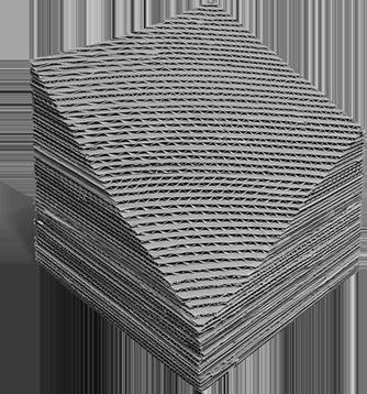
| Topography | Joshua Tree Topography Single Quadrant Model
14
DP_02
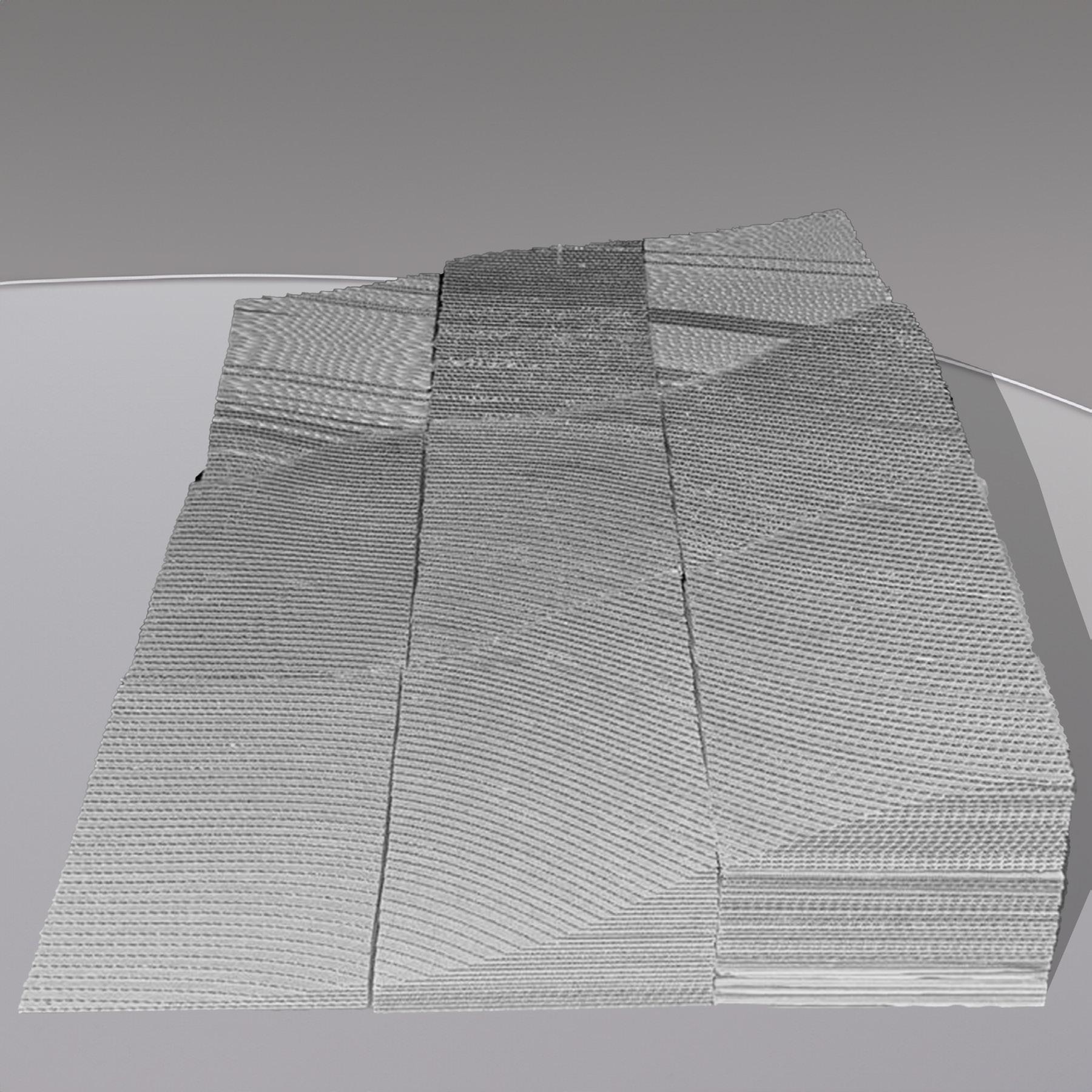
DP_02 | Topography | Joshua Tree Complete Topography Model
15
DESIGN PROJECT 3: STANDARD DEVIATION
Design project 3 revolves around the creation of The Noah Purifoy Art Center and Studios, envisioned as a cultural haven for the newly established artist residence program sponsored jointly by the Noah Purifoy Foundation and Pomona College of the Claremont Colleges. This ambitious undertaking is designed to serve as a robust cultural infrastructure, providing artists with a one-year sojourn to explore and express their creative passions without limitations. The project’s essence is rooted in its unwavering support for contemporary solo artists, offering them a platform to contribute meaningfully to the cultural and aesthetic legacy of Black Americans. Aligned with the Noah Purifoy Foundation’s commitment to fostering equity and inclusion, the artist-inresidence program is a direct catalyst for artistic endeavors aimed at initiating social change and awareness.
Comprising essential elements such as the main entrance and lobby, a coffee kiosk, gallery space, production areas with storage, six artist studios, administrative offices, restrooms, circulation spaces, bicycle storage, and an inviting outdoor courtyard, the program is meticulously curated to fulfill the diverse needs of resident artists. Nestled in downtown Claremont at the intersection of Alley 43 and West 1st Street, the site itself becomes an integral part of the artistic narrative, contributing to the project’s vision of creating a vibrant and inclusive space for artistic exploration and cultural dialogue.
16
17 SITE PLAN 5 6. Administrative Office Spaces 7. Restrooms 8. Circulation 9. Bicycle Storage 10. Outdoor Space/Courtyard ALLEY 5 5 5 N 1 10 8 5 5 LEGEND 1. Main Entrance and Lobby 2. Coffee Kiosk 3. Gallery Space 4. Production Spaces/ Storage 5. Artist Studios W 1ST ST SCALE 1/16" = 1'
43 10 DP_03 | Standard Deviation | Site Plan
ALLEY
Generative Diagram
Standard Deviation | Generative Diagram
18
DP_03 |
19 1ST
EAST ELEVATION 8 8 8 9 7 6 3 1 2 1 10 10 5 5 4 3 3 3 2 6. Administrative Office Spaces 7. Restrooms 8. Circulation 9. Bicycle Storage 10. Outdoor Space/Courtyard LEGEND 1. Main Entrance and Lobby 2. Coffee Kiosk 3. Gallery Space 4. Production Spaces/ Storage 5. Artist Studios N N A A B SCALE 1/8" = 1' B SCALE 1/8" = 1' DP_03 | Standard Deviation | Floor Plan & Elevation
FLOOR
EAST SECTION AA 2ND FLOOR 3 3 3 9 5 5 6 5 5 5 4 4 3 8 10 10 10 3 8 8 8 8 7 7 7 N 6 6 4 5 5 2 1 LEGEND 1. Main Entrance and Lobby 2. Coffee Kiosk 3. Gallery Space 4. Production Spaces/ Storage 5. Artist Studios 5 7 6. Administrative Office Spaces 7. Restrooms 8. Circulation 9. Bicycle Storage 10. Outdoor Space/Courtyard N A B SCALE 1/8" = 1' SCALE 1/8" = 1' B A 20 DP_03 | Standard Deviation | Floor Plan & Section
21 SOUTH SECTION BB SOUTH ELEVATION UNDERGROUND FLOOR 6 6 6 LEGEND 1. Main Entrance and Lobby 2. Coffee Kiosk 3. Gallery Space 4. Production Spaces/ Storage 5. Artist Studios 6. Administrative Office Spaces 7. Restrooms 8. Circulation 9. Bicycle Storage 10. Outdoor Space/Courtyard 4 4 10 5 5 5 4 2 7 3 N N 8 8 N 6 6 SCALE 1/8" = 1' A SCALE 1/8" = 1' B B SCALE 1/8" = 1' A DP_03 | Standard Deviation | Floor Plan, Elevation, & Section


Exterior Perspective Rendering Interior Perspective Rendering 22 DP_03 | Standard Deviation | Renderings


23
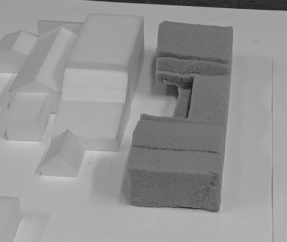
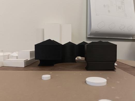
DP_03 | Standard Deviation | Site & Massing Model


DP_03 | Standard Deviation | Site & Massing Model 24
DESIGN PROJECT 4: THE OTHER INSTITUTO BRINCANTE
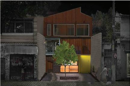
The Brincante Institute, designed by Bernardes Arquitetura, serves as a significant precedent for analyzing and representing black box theatre design and its connection to the urban environment. The architectural concept emphasizes direct communication between the building and the street, strengthening its relationship with the vibrant neighborhood of Vila Madalena. Founded by the artist couple Antonio Nóbrega and Rosane Almeida on November 22, 1992, and acquiring the status of an institute on March 2, 2001, the Brincante Institute has dedicated over two decades to promoting Brazilian culture. Its activities include school theater and training for young people, children, artists, and educators, all aimed at expanding cultural and social awareness through music and dance from scratch. By focusing on the analysis and representation of this project, there was an exploration of how architectural elements and design strategies can create a dynamic interaction between the theater space and the urban fabric of Vila Madalena.
Giovanni Salgado | Fatima Jeffery
25


26 GROUND FLOOR PLAN Scale 1/8”= 1” 7 8 1 2 3 6 4 5 9 1 SECTION Scale 1/8”= 1” LEGEND 1. OUTDOOR PATIO 2. ENTRANCE 3. TICKET OFFICE 4. STORAGE 5. KITCHEN 6. BATHROOM 7. GRANDSTAND 8. STAGE 9. BACKSTAGE 10. BALCONY 11. FOOTBRIDGE 12. GARDEN 13. MEETING ROOM 14. OFFICE 15. CHANGING ROOM 16. KITCHEN 17. REHEARSAL ROOM LEGEND 1. OUTDOOR PATIO 2. ENTRANCE 3. TICKET OFFICE 4. STORAGE 5. KITCHEN 6. BATHROOM 7. GRANDSTAND 8. STAGE 9. BACKSTAGE 10. BALCONY 11. FOOTBRIDGE 12. GARDEN 13. MEETING ROOM 14. OFFICE 15. CHANGING ROOM 16. KITCHEN 17. REHEARSAL ROOM 1 11 13 10 15 17 12 4 7 8 9 1 7 1 1 2 8 N Dp_04 | Instituto Brincante | Plans & Elevations


FIRST FLOOR PLAN Scale 1/8”= 1” 1 2 3 LEGEND 1. OUTDOOR PATIO 2. ENTRANCE 3. TICKET OFFICE 4. STORAGE 5. KITCHEN 6. BATHROOM 7. GRANDSTAND 8. STAGE 9. BACKSTAGE 10. BALCONY 11. FOOTBRIDGE 12. GARDEN 13. MEETING ROOM 14. OFFICE 15. CHANGING ROOM 16. KITCHEN 17. REHEARSAL ROOM LEGEND 1. OUTDOOR PATIO 2. ENTRANCE 3. TICKET OFFICE 4. STORAGE 5. KITCHEN 6. BATHROOM 7. GRANDSTAND 8. STAGE 9. BACKSTAGE 10. BALCONY 11. FOOTBRIDGE 12. GARDEN 13. MEETING ROOM 14. OFFICE 15. CHANGING ROOM 16. KITCHEN 17. REHEARSAL ROOM 1 1 1 SECOND FLOOR PLAN Scale 1/8”= 1” 1 3 3 2 5 4 N N 27 Dp_04 | Instituto Brincante | Plans & Elevations

28 FIRST FLOOR GROUND FLOOR SCHOOL DAY SHOW TIME INTERMISSION SECOND FLOOR ACTIVITY DIAGRAM 11 12 13 14 15 16 16 17 18 1 01 5 8 2 3 4 6 9 11 12 13 14 15 16 17 18 11 12 13 14 15 16 17 18 1 01 5 8 2 3 4 6 9 LEGEND 1. OUTDOOR PATIO 2. ENTRANCE 3. TICKET OFFICE 4. STORAGE 5. KITCHEN 6. BATHROOM 7. GRANDSTAND 8. STAGE 9. BACKSTAGE 10. STAIRS 11. GARDEN 12. FOOTBRIDGE 13. BALCONY 14. MEETING ROOM 15. OFFICE 16. CHANGING ROOM 17. KITCHEN 18. REHEARSAL ROOM FIGURE KEY 1. PERFORMERS 2. STAFF 3. VISITORS LEGEND 1. OUTDOOR PATIO 2. ENTRANCE 3. TICKET OFFICE 4. STORAGE 5. KITCHEN 6. BATHROOM 7. GRANDSTAND 8. STAGE 9. BACKSTAGE 10. STAIRS 11. GARDEN 12. FOOTBRIDGE 13. BALCONY 14. MEETING ROOM 15. OFFICE 16. CHANGING ROOM 17. KITCHEN 18. REHEARSAL ROOM 19. HALLWAY FIRST FLOOR GROUND FLOOR SECOND FLOOR PRIVATE PUBLIC 18 15 14 16 19 17 10 12 13 10 7 11 SECTION BOH FOH CIRCULATION STREET FRONTAGE 9 8 7 4 1 13 18 12 14 16 10 11 10 6 9 4 5 3 8 7 2 1 8 7 1 2 PUBLIC VS PRIVATE DIAGRAM N Dp_04
| Instituto Brincante | Diagrams


FACADE VARIATIONS 29
Dp_04 | Instituto Brincante | Facade Variations
30 EXISTING ELEVATION Scale 1/8”= 1” PROPOSED ELEVATION Scale 1/8”= 1” 1 2 3 4 1 2 3
Facade Generation
Dp_04 | Instituto Brincante | Facde Generation
MATERIALS


Dp_04 | Instituto Brincante | Diagrams
ALUMINIUM
CMU
MOSAIC COBBLESTONE
N R. PURPURINA
Courtyard Analysis Diagram
LIGHT AT 6:30 AM LIGHT AT 12:30 PM LIGHT AT 6:30 PM 31
LIGHTING DIAGRAM


32
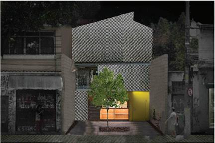
FACADE PERSPECTIVE RENDERED SECTION
PROPOSED
Dp_04 | Instituto Brincante | Renderings

EXISTING AND PROPOSED SECTION BAY MODELS 33
Dp_04 | Instituto Brincante | Physical Model
DESIGN PROJECT 5: THE MARIACHI CULTURAL ARTS CENTER CIRCLE (MCACC)
The Mariachi Cultural Arts Center Circle (MCACC) is a dedicated space in Boyle Heights celebrating mariachi music and cultural arts. Its circular design symbolizes unity and the continuous nature of cultural traditions. The center serves as a hub where individuals from diverse backgrounds can come together to experience and celebrate various forms of art and heritage.
MCACC focuses on preserving and promoting cultural practices through exhibitions, performances, and educational programs. By honoring customs and legacies, it aims to strengthen community identity and encourage active participation in cultural activities. Overall, the MCACC is more than just a building; it is a vibrant space for cultural learning and connection.
34

35 MASTER PLAN 2030
MASTERPLAN 2030
DP_05
| (MCACC) | Master Plan


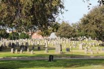

LA PLAZAS 145,960 sqft 54,456 sqft Mariachi Plaza Existing 35,278 sqft Jerry Moss Plaza Paseo De La Plaza 188,729 sqft Pershing Square 57,031sqft Ge en Plaza 1st St 1st St 1st St 1st St 15,661 sqft Sanrio Japanese Village (Plaza) SHillSt LASt 63,952 sqft Mariachi Plaza Proposed 2024 1st St 135,183 sqft Mariachi Plaza Proposed Master Plan 2030 1st St Legend Site Parks Dog Park Playground Regreation Center Cementary Hollenbeck Park Boyle Heights Sports Center & Park Pecan Recreation Center Evergreen Recreation Center MSGR. Ramon Garcia Regreation Center Prospect Park Evergreen Cementary Odd Fellows Cementary Los Angeles River Dodger Stadium Important Landmarks Dodger Stadium L.A. River 1stStreet Legend Site Parks Dog Park Playground Regreation Center Cementary Hollenbeck Park Boyle Heights Sports Center & Park Pecan Recreation Center Evergreen Recreation Center MSGR. Ramon Garcia Regreation Center Prospect Park Evergreen Cementary Odd Fellows Cementary Los Angeles River Dodger Stadium Important Landmarks Dodger Stadium L.A. River 1stStreet Legend Site Parks Dog Park Playground Regreation Center Cementary Hollenbeck Park Boyle Heights Sports Center & Park Pecan Recreation Center Evergreen Recreation Center MSGR. Ramon Garcia Regreation Center Prospect Park Evergreen Cementary Odd Fellows Cementary Los Angeles River Dodger Stadium Important Landmarks Dodger Stadium L.A. River 1stStreet Green Spaces GREEN SPACES 36 DP_05 | (MCACC) | Diagrams

DP_05 | (MCACC) | Site Plan, Diagram & Elevation
37
SITE SECTION SCALE 1/16” =1’ SITE PLAN SCALE 3/32” =1’ GROSS FLOOR & CIRCULATION AREA N Total Program: 25,770 sqft (60%) Total Circulation: 10,507sqft (40%) 3rd Flr: Program: 9,083 sqft (78%) Circulation: 2,738 sqft (22%) Total: 11,821 sqft 2nd Flr: Program:8,970 sqft (72%) Circulation: 3,573 sqft(28%) Total: 12,543 sqft 1st Flr: Program: 7,717 sqft (87%) Circulation: 1,187 sqft (13%) Total: 8904 sqft 4th Flr (Catwalk): Circulation: 3,009 sqft (100%)


NEIGHBORHOOD
Narrow horz shiplab vinyl Facade Square windows with wood decorative trim Wide Horz clapboard bevel cement Facade Square windows with wood decorative trim Vert Wood Board & Stucco Facade Square windows Stucco Facade Square windows Hybrid Facade Horz wood clapboard scallops siding Horz wood shingle clapboard siding Coarse Stucco Square windows Coarse Stucco Facade Sqaure windows Brick Facade Square and Arch windows with depth Hybrid Facade Brick Vinyl Horz Bevel Siding Coarse Stucco Square Windows x1 x2 Facade Materials Used VARIABLES: Color Windows Siding: vertical, shingle, and horizontal Brick Stucco Height variations THE IN BETWEEN Architectural features
North Elevation Row Houses 38 DP_05 | (MCACC) | Analysis
FACDE STUDY
(Planning)
GENERATIVE DIAGRAM 3 2 1 6 x1 x3 x2 4 5 39
DP_05 | (MCACC) | Generative Diagram


PROGRAM KEY: CIRCULATION MULTI PURPOSE ROOM FRONT OF HOUSE MUSIC STUDIO PRACTICE ROOM GALLERY BACK OF BOX THEATER CAFE BAR BACK OF HOUSE PROGRAMMATIC MODELS 1-4 VERSION 1 VERSION 2 VERSION 3 VERSION 4 FINAL PROGRAMMATIC MODEL 40 DP_05 | (MCACC) | Programmatic Models


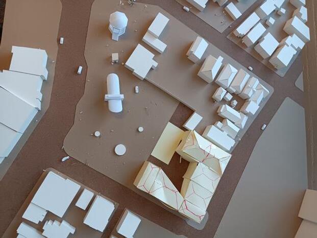

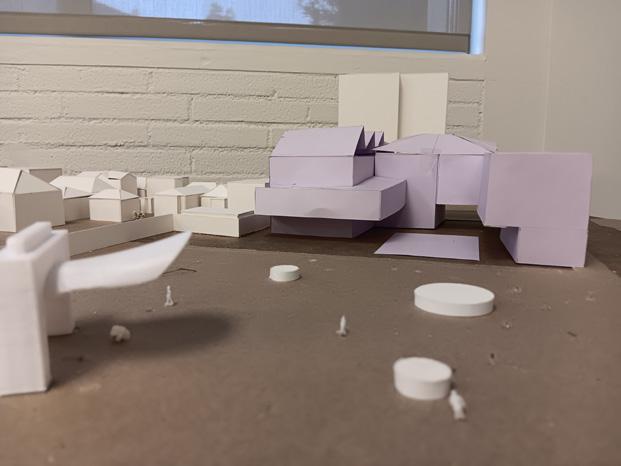


41 VERSION 1 VERSION 2 VERSION 3 MASSING MODELS 1-3
DP_05 | (MCACC) | Massing Models


42 VERSION 4 VERSION 5 VERSION 6 MASSING MODELS 4-6
DP_05 | (MCACC) | Massing Models


43 FINAL MASSING MODEL
DP_05 | (MCACC) | Final Massing Model

44 DP_05 | (MCACC) | Plan & Section N 1ST FLOOR SCALE 1/16” = 1’ Legend 1) Black Box 2) Stage 3) Gallery 4) Multi-Purpose Room 5) Wood shop storage 6) Music studio 7) Practice Room 8) Foyer 9) Outdoor Theatre 10) FOH W/C 11) BOH W/C 12) Changing Room 13) Freight Elevator 14) Breakroom 15) Outdoor patio 16) Retail and Reception 17) Bar /Café 18) Catwalk 19) Control Booth 20) Admin 21) loading Trash 22) Ticket Booth 23) Mech Rm 6 21 3 4 5 8 7 7 7 7 7 7 7 9 10 10 10 A A SECTION AA SCALE 1/16” = 1’ 1 21 5 13 23 6 12 F.F 0’ - 0” 2nd Flr 13’ - 6” 3rd Flr 27’ T.O.R 50’ 8”

45 DP_05 | (MCACC) | Plan & Section N 11 11 2ND FLOOR SCALE 1/16” = 1’ Legend Black Box 2) Stage 3) Gallery 4) Multi-Purpose Room 5) Wood shop storage 6) Music studio 7) Practice Room 8) Foyer 9) Outdoor Theatre 10) FOH W/C 11) BOH W/C 12) Changing Room 13) Freight Elevator 14) Breakroom 15) Outdoor patio 16) Retail and Reception 17) Bar /Café 18) Catwalk 19) Control Booth 20) Admin 21) loading Trash 22) Ticket Booth 23) Mech Rm 15 12 8 6 6 7 14 7 4 7 13 1 2 9 10 10 B B SECTION BB SCALE 1/16” = 1’ 16 8 20 7 6 6 8 12 7 9 17 14 F.F 0’ 0” 2nd Flr 13’ 6” 3rd Flr 27’ T.O.R 56’ - 10”

46 DP_05 | (MCACC) | Plan & Section 17 N Legend 3RD FLOOR SCALE 1/16” = 1’ 4TH FLOOR (CATWALK) SCALE 1/16” = 1’ Black Box 2) Stage 3) Gallery 4) Multi-Purpose Room 5) Wood shop storage 6) Music studio 7) Practice Room 8) Foyer 9) Outdoor Theatre 10) FOH W/C 11) BOH W/C 12) Changing Room 13) Freight Elevator 14) Breakroom 15) Outdoor patio 16) Retail and Reception 17) Bar /Café 18) Catwalk 19) Control Booth 20) Admin 21) loading Trash 22) Ticket Booth 23) Mech Rm 1 19 20 20 8 22 16 15 23 9 2 10 10 C c 10 19 PERSPECTIVE SECTION CC 20 20 8 4 8 4 21 F.F 0’ 0” 2nd Flr 13’ 6” T.O.R 58’ 1”
EAST ELEVATION
SCALE 1/16” = 1’


SOUTH ELEVATION
SCALE 1/16” = 1’
| (MCACC) | Elevations
47
DP_05


| (MCACC) | Renderings
48
EXTERIOR PERSPECTIVE INTERIOR PERSPECTIVE
DP_05
DESIGN PROJECT 6: 1952 STEVENSON RESIDENCE ANALYSIS AND REPRESENTATION
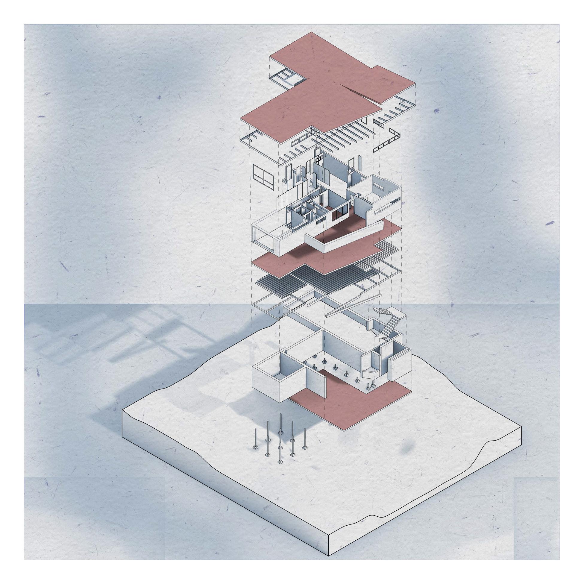
Tasked with digitally reproducing the 1952 Stevenson Residence at 3206 Melemele Pl, Honolulu, HI 96822. Deliverables include a 3D model in Rhino (.3dm format) with proper layer management and a digital planset (plan, roof plan, section, elevations) with a 24x36” title block.
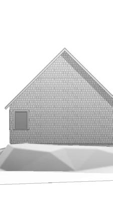
Building on the 3D model, three stylistic forms were created to illustrate architectural communication tools: diagramming, illustrating, and abstracting. Deliverables include an exploded isometric diagram of the roof tectonics, circulation, and spatial zones in a square format; a visually simple elevation illustration with shadows and shading in a 12x12” square format, reflecting a 1965-1975 visual theme; and an abstract graphic composition incorporating elements from three Alfred Preis houses, focusing on color palette, line weight, and graphic quality, avoiding unrelated text and graphics.
49

DP_06 | 1952 STEVENSON RESIDENCE| Plans
50

| 1952 Stevenson Residence| Plans
51
Dp_06
52
Dp_06 | 1952 Stevenson Residence| Exploded Diagram Of Tectonics

| 1952 Stevenson Residence | Illustration
53
Dp_06

| 1952 Stevenson Residence | Abstraction
54
Dp_06
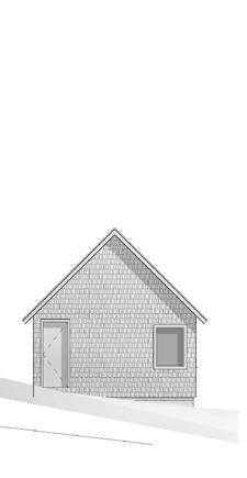
DESIGN PROJECT 7: BLACK GABLES / OMAR GANDHI
This project involves analyzing the Black Gables Cabin, designed by Omar Gandhi, with a focus on its construction methods and structural components. The foundation is a slab on grade with shallow frost protected footing, supporting a light wood-framed wall and roof structure. The primary objective is to speculate and understand the architectural sections of the cabin by analyzing available photos and the described foundation. This exercise emphasizes learning to communicate through technical drawings and understanding various types of assemblies. The process includes examining photos to approximate roof pitch and wall height, followed by class discussions to refine these approximations and developing a mini-Construction Document Set using Revit. Overall, this serves as an introduction to architectural documentation and the methods architects use to convey design ideas for construction, emphasizing both theoretical understanding and practical application.
Giovanni Salgado | Cynthia Lopez
55


56 Dp_07 | Black Gables / Omar Gandhi | Plan Sets REF. 1 1 3 3 2 2 4 4 5 5 6 6 7 7 8 8 9 9 10 10 5' 6" 6' 10" 7' 6" 0" 9' 6" 13' 7'0" 16' 4" 49' 6" 23' 6" A-207 3' 0" 5' 0" 5'-6" 2' 0" 3' 0" 10" 7' 10" 7' 10" 5' 8" CONCRETE FLOOR ENTIRE UNIT TO RECIEVE POLISHED CONCRETE WITH Room 1 Room 2 Room LIVING 4 BATH KITCHEN/LIVING 7 A-202 1 A-207 23'6 1/2" 49' - 6 1/2" STUIDIO SCALE: 1/8" DRAWN BY: RC/GS PROJECT NO. 5442.01 EX 1.2 JUINTOW LIN BLACK GABLES CLIENT Giovanni Salgado 3801 Temple Ave, Pomona, CA 91768 https://www.cpp.edu/ (909) 869-7659 Billy Bronco 3801 Temple Ave, Pomona, CA 91768 A-101 MAIN FLOOR PLAN CENTER LINE DOOR TAG 101 A101 SIM SECTION Name Elevation Room name 101 1t A101 1 Ref 1 Ref 1 Ref 1 Ref EXTERIOR ELEVATION STUIDIO SCALE: 1/8" CHECKED BY: DRAWN BY: RC/GS PROJECT NO. JUINTOW LIN BLACK GABLES CLIENT Rosendo Cervantes Giovanni Salgado 3801 Temple Ave, Pomona, CA 91768 https://www.cpp.edu/ (909) 869-7659 Billy Bronco 3801 Temple Ave, Pomona, CA 91768 G-101 COVER SHEET BLACK GABLES Louisdale, Nova Scotia, Canada PROJECT DATA SITE PLAN SHEET LIST No. OF STORIES: UNITS: 2 OCCUPANCY: 3 ZONNING: RAREA INFORMATION: (E) MAIN DWELLING - 1200 SF (E) DETACHED STUDIO - 450 SF Total SF 1650 SF SCOPE OF WORK VICINITY MAP SYMBOL LEGEND EXISTING CONSTRUCTION WITH MAIN DWELLING HAVING AN KITCHEN, DINING, LIVING, MECHANICAL, OFFICE, GALLERY, BATH, AND MASTER BEDROOM. A SEPERATED DETACHED STUDIO CONSISTING OF ONE STUDIO, ONE BATH AND DARK ROOM. # Sheet Name A-101MAIN FLOOR PLAN A-102ACCESSORY FLOOR PLAN A-103REFLECTED CEILING PLAN A-104REFLECTED CEILING PLAN ACC A-105ROOF PLAN A-601AXONOMETRIC A-106ROOF PLAN ACC G-101COVER SHEET A-201EXTERIOR ELEVATIONS A-202EXTERIOR ELEVATIONS A-203EXTERIOR ELEVATIONS A-204EXTERIOR ELEVATIONS A-205EXTERIOR ELEVATION EAST A-206EXTERIOR ELEVATIONS WEST A-207WEST CROSS SECTIONS ARCHITECTS: OMAR GANDHI ARCHITECT LOCATION: LOUISDALE, NOVA SCOTIA, CANADA FOUNDATION: CONCRETE SLAB ON GRADE CONSTUCTION TYPE: WOOD FRAMING PROPERTY TYPE: PRIVATE RESIDENCE YEAR: 2014 CONTRACTOR: HARBOURVIEW CONSTRUCTION LIMITED 3 SITE PLAN 1/32" = 1' N


57 Dp_07 | Black Gables / Omar Gandhi | Plan Sets 13 13 11 11 18 18 17 17 14 14 12 12 16 16 15 15 8' 9" 9' 0" 2' 9" 6' 11" 10' 7" 4' 10" 27' 6" 15' 6" 3' 0" 7' 10" 8' 0" 2' - 0" CONCRETE FLOOR WITH NATURAL GRAY FINISH. STUDIO 6 A-204 1 STUIDIO SCALE: 1/8" CHECKED BY: DRAWN BY: RC/GS PROJECT NO. 5442.01 EX 1.2 JUINTOW LIN BLACK GABLES CLIENT Rosendo Cervantes Giovanni Salgado 3801 W Temple Ave, Pomona, CA 91768 https://www.cpp.edu/ (909) 869-7659 Billy Bronco 3801 W Temple Ave, Pomona, CA 91768 A-102 ACCESSORY FLOOR PLAN 1 1 3 3 2 2 4 4 5 5 6 6 7 7 8 8 9 9 10 10 A-207 DROPPED CEILINGS: ALL CEILINGS TO RECIEVE GYPSOME BOARD (DRY WALL) A-202 1 A-207 CEILING LIGHTS VAULTED CEILINGS ALL CEILINGS TO RECIEVE GYPSOME BOARD (DRY WALL) 617 STUIDIO SCALE: 1/8" 1' RC/GS PROJECT NO. 5442.01 EX 1.2 N BLACK GABLES CLIENT Rosendo Cervantes Giovanni Salgado 3801 W Temple Ave, Pomona, CA 91768 https://www.cpp.edu/ (909) 869-7659 Billy Bronco 3801 W Temple Ave, Pomona, CA 91768 A-103 REFLECTED CEILING PLAN
| Black Gables / Omar Gandhi | Plan Sets
58
13 13 11 11 18 18 17 17 14 14 12 12 16 16 15 15 ALL CEILINGS TO RECIEVE GYPSOME BOARD (DRY WALL) A-204 1 STUIDIO SCALE: 1/8" CHECKED BY: DRAWN BY: RC/GS PROJECT NO. 5442.01 EX 1.2 JUINTOW LIN BLACK GABLES CLIENT Rosendo Cervantes Giovanni Salgado 3801 Temple Ave, Pomona, CA https://www.cpp.edu/ (909) 869-7659 Billy Bronco 3801 Temple Ave, Pomona, CA 91768 A-104 REFLECTED CEILING PLAN REF. - - 0 - - 04030-103020504020 -4 - 0 --80908013012040 1 1 3 3 2 2 4 4 5 5 6 6 7 7 8 8 9 9 10 10 BUILDING FOORTPRINT 12:12 12:12 12:12 12:12 FULL METAL JACKET ROOF JOINS 11' 9" 11' 9" 50' 1/2" 1' 0" 1' 0" A-202 1 A-207 STUIDIO SCALE: 1/8" DRAWN BY: RC/GS PROJECT NO. 5442.01 EX 1.2 JUINTOW LIN BLACK GABLES CLIENT Giovanni Salgado 3801 Temple Ave, Pomona, CA 91768 https://www.cpp.edu/ (909) 869-7659 Billy Bronco 3801 Temple Ave, Pomona, CA 91768 A-105 ROOF PLAN
Dp_07


59 Dp_07
STUIDIO SCALE: 1/8" RC/GS PROJECT NO. 5442.01 EX 1.2 BLACK GABLES CLIENT Rosendo Cervantes Giovanni Salgado 3801 W Temple Ave, Pomona, CA 91768 https://www.cpp.edu/ (909) 869-7659 Billy Bronco 3801 W Temple Ave, Pomona, CA 91768 A-601 AXONOMETRIC Lower Level 0' - 0" Plate Height 9' - 0" Roof 22' - 2" 4 5 6 7 8 9 10 A-207 12' 6" 7' 6" 7' 0" 9' 6" 13' 0" 49' 6" 9' 0" 13' 0" 22' 0" Metal Jacket Roof Cedar Shingles Aluminum Framed Windows Aluminum Fascia STUIDIO PROJECT NO. 5442.01 1.2 BLACK GABLES CLIENT Rosendo Cervantes Giovanni Salgado 3801 Temple Ave, Pomona, CA 91768 https://www.cpp.edu/ (909) 869-7659 Billy Bronco 3801 Temple Ave, Pomona, CA 91768 A-201 NORTH ELEVATION
| Black Gables / Omar Gandhi | Plan Sets


Dp_07 | Black Gables / Omar Gandhi | Plan Sets


60
Studio Level -6' - 0" Plate Height 3' - 0" 18 17 14 16 15 Roof 12' - 3" 8' 9" 9' 0" 2' 10" 6' 11" 27' 6" 9' 0" 9' 3" 18' 3" Metal Jacket Roof Cedar Shingles Aluminum Fascia STUIDIO SCALE: 1/8" 1' CHECKED BY: DRAWN BY: RC/GS PROJECT NO. 5442.01 EX 1.2 JUINTOW LIN BLACK GABLES CLIENT Rosendo Cervantes Giovanni Salgado 3801 Temple Ave, Pomona, CA 91768 https://www.cpp.edu/ (909) 869-7659 Billy Bronco 3801 Temple Ave, Pomona, CA 91768 A-202 NORTH ACCES. ELEVATIONS Lower Level 0' - 0" Plate Height 9' - 0" Roof 22' - 2" 4 5 6 7 8 9 10 A-207 13' 0" 9' 0" 49' 6" 22' 0" 12' 6" 6" 0" 9' 6" 13' 0" Metal Jacket Roof Cedar Shingles Aluminum Framed Windows STUIDIO PROJECT NO. 5442.01 EX 1.2 BLACK GABLES CLIENT Rosendo Cervantes Giovanni Salgado 3801 Temple Ave, Pomona, CA 91768 https://www.cpp.edu/ (909) 869-7659 Billy Bronco 3801 Temple Ave, Pomona, CA 91768 A-203 SOUTH ELEVATION


| Black Gables / Omar Gandhi | Plan Sets


61
Studio Level -6' - 0" Plate Height 3' - 0" 18 17 14 16 15 Roof 12' - 3" 8' 9" 9' 0" 2' 9" 6' 11" 27' 6" 9' 3" 9' 0" 18' 3" Aluminum Framed Windows Metal Jacket Roof Cedar ShinglesSTUIDIO SCALE: 1/8" CHECKED BY: DRAWN BY: RC/GS PROJECT NO. 5442.01 1.2 JUINTOW LIN BLACK GABLES CLIENT Rosendo Cervantes Giovanni Salgado 3801 Temple Ave, Pomona, CA 91768 https://www.cpp.edu/ (909) 869-7659 Billy Bronco 3801 Temple Ave, Pomona, CA 91768 A-204 SOUTH ACCES. ELEVATIONS Lower Level 0' - 0" Plate Height 9' - 0" Roof 22' - 2" Studio Level - - 0" Plate Height 2 - 0" 1 3 2 13 11 12 Roof 12' - 3" 10' 7" 10" 15' 6" 16' 4" 7' 1" 23' 6" 9' 3" 9' 0" 18' 3" 13' 2" 9' 0" 22' 0" Aluminum Framed Windows Cedar Shingles Metal Jacket Roof Aluminum Fascia Detail A-207 STUIDIO PROJECT NO. 5442.01 1.2 BLACK GABLES CLIENT Rosendo Cervantes Giovanni Salgado 3801 Temple Ave, Pomona, CA 91768 https://www.cpp.edu/ (909) 869-7659 Billy Bronco 3801 Temple Ave, Pomona, CA 91768 A-205 EAST ELEVATION
Dp_07


Dp_07 | Black Gables / Omar Gandhi | Plan Sets

62
Lower Level 0' - 0" Plate Height 9' - 0" Roof 22' - 2" Studio Level -6' - 0" Plate Height 3' - 0" 1 3 2 13 11 12 Roof 12' - 3" 9' 3" 9' 0" 18' 3" 13' 2" 9' 0" 22' 0" 1" 16' 4" 4' 10" 10' 7" 15' 6" 23' 6" Aluminum Framed Windows Aluminum Fascia Detail Metal Jacket Roof Cedar Shingles Aluminum Clad Entry Door 12 12 12 12 STUIDIO SCALE: 1/8" 1' CHECKED BY: DRAWN BY: RC/GS PROJECT NO. 5442.01 EX 1.2 JUINTOW LIN BLACK GABLES CLIENT Rosendo Cervantes Giovanni Salgado 3801 Temple Ave, Pomona, CA 91768 https://www.cpp.edu/ (909) 869-7659 Billy Bronco 3801 Temple Ave, Pomona, CA 91768 A-206 WEST ELEVATION Lower Level 0' - 0" Plate Height 9' - 0" Roof 22' - 2" 1 3 2 LIVING A-207 7' 1" 16' 4" 23' 6" 22' 0" Lower Level 0' - 0" Plate Height 9' - 0" Roof 22' - 2" 4 8 10 22' 5 13/16" 27' 0 11/16" 22' 2" 49' 6" STUIDIO PROJECT NO. 5442.01 EX 1.2 BLACK GABLES CLIENT Rosendo Cervantes Giovanni Salgado 3801 Temple Ave, Pomona, CA 91768 https://www.cpp.edu/ (909) 869-7659 Billy Bronco 3801 Temple Ave, Pomona, CA 91768 A-207 CROSS SECTIONS 1/8" = 1'-0" 1 WEST SECTION -MAIN UNIT 1/8" = 1'-0" 2 SOUTH SECTION -MAIN UNIT

63
Dp_07 | Black Gables / Omar Gandhi | Wood Frame Model

64
Dp_07 | Black Gables / Omar Gandhi | Wood Frame Model
