Instruction Manual
3582, 582i, and 3583
June 2010
Maintenance OUTPUT TO STEM POSITION INDICATOR OR RECORDER RELAY
BELLOWS ROTARY SHAFT ARM
INPUT AXIS
SUPPLY
WARNING NOZZLE
TRAVEL PIN
FLAPPER
BEAM FEEDBACK AXIS PIVOT CAM 22A7964-A A2454-4 / IL
OPERATIONAL QUADRANT
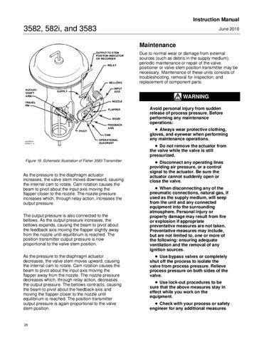
Figure 19. Schematic Illustration of Fisher 3583 Transmitter
As the pressure to the diaphragm actuator increases, the valve stem moves downward, causing the internal cam to rotate. Cam rotation causes the beam to pivot about the input axis moving the flapper closer to the nozzle. The nozzle pressure increases which, through relay action, increases the output pressure. The output pressure is also connected to the bellows. As the output pressure increases, the bellows expands, causing the beam to pivot about the feedback axis moving the flapper slightly away from the nozzle until equilibrium is reached. The position transmitter output pressure is now proportional to the valve stem position. As the pressure to the diaphragm actuator decreases, the valve stem moves upward, causing the internal cam to rotate. Cam rotation causes the beam to pivot about the input axis moving the flapper away from the nozzle. The nozzle pressure decreases which, through relay action, decreases the output pressure. The bellows contracts, causing the beam to pivot about the feedback axis and moving the flapper closer to the nozzle until equilibrium is reached. The position transmitter output pressure is again proportional to the valve stem position.
28
Due to normal wear or damage from external sources (such as debris in the supply medium), periodic maintenance or repair of the valve positioner or valve stem position transmitter may be necessary. Maintenance of these units consists of troubleshooting, removal for inspection, and replacement of component parts.
Avoid personal injury from sudden release of process pressure. Before performing any maintenance operations: D Always wear protective clothing, gloves, and eyewear when performing any maintenance operations. D Do not remove the actuator from the valve while the valve is still pressurized. D Disconnect any operating lines providing air pressure, or a control signal to the actuator. Be sure the actuator cannot suddenly open or close the valve. D When disconnecting any of the pneumatic connections, natural gas, if used as the supply medium, will seep from the unit and any connected equipment into the surrounding atmosphere. Personal injury or property damage may result from fire or explosion if appropriate preventative measures are not taken. Preventative measures may include, but are not limited to, one or more of the following: ensuring adequate ventilation and the removal of any ignition sources. D Use bypass valves or completely shut off the process to isolate the valve from process pressure. Relieve process pressure on both sides of the valve. D Use lock-out procedures to be sure that the above measures stay in effect while you work on the equipment. D Check with your process or safety engineer for any additional measures