Instruction Manual
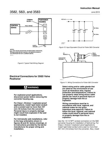
3582, 582i, and 3583 TERMINAL BLOCK
CONTROL DEVICE
June 2010
POSITIONER HOUSING
FIELD WIRING
21B2335-D A6012/IL
EARTH GROUND NOTES: FOR TROUBLESHOOTING OR MONITORING OPERATION, AN INDICATING DEVICE CAN BE A VOLTMETER ACROSS A 250 OHM RESISTOR OR A CURRENT METER. A3875*/IL
Figure 10. Input Equivalent Circuit for Fisher 582i Converter
I/P MODULE
FIELD WIRING CONNECTION
CONVERTER HOUSING
Figure 9. Typical Field Wiring Diagram
Electrical Connections for 3582i Valve Positioner
A7140 / IL
Figure 11. Wiring Connections for Fisher 582i Converter
WARNING For explosion-proof applications, disconnect power before removing the converter housing cap. For Class I, Division 1 explosion-proof applications, install rigid metal conduit and a conduit seal no more than 457 mm (18 inches) from the converter. Personal injury or property damage might result from explosion if the seal is not installed. For intrinsically safe installations, refer to the loop schematics shown in figures 28 and 30, factory drawings, or to instructions provided by the barrier manufacturer for proper wiring and installation.
18
Select wiring and/or cable glands that are rated for the environment of use (such as hazardous area, ingress protection and temperature). Failure to use properly rated wiring and/or cable glands can result in personal injury or property damage from fire or explosion. Wiring connections must be in accordance with local, regional, and national codes for any given hazardous area approval. Failure to follow the local, regional, and national codes could result in personal injury or property damage from fire or explosion. Use the 1/2-14 NPT conduit connection on the 582i converter housing for installation of field wiring. For Class I, Division I explosion-proof applications, install rigid metal conduit and a seal no more than 457 mm (18 inches) from the converter. Also, install